Embed Size (px)
Citation preview

Printed in USA P/N 132607 rev. HFeb 2012
SureCross™Wireless I/O Network
Product Manual

The manufacturer does not take responsibility for the violation of any warning listed in this document.
CAUTION. Make no modifications to this product. Any modifications to this product not expressly approved by Banner Engineering could void the user’s authority to operate the product. Contact the Factory for more information.
Lightning Arrestors/Surge Protection. Always use lightning arrestors/surge protection with all remote antenna systems to avoid invalidating the Banner Engineering Corp. warranty. No surge protector can absorb all lightning strikes. Do not touch the SureCross device or any equipment connected to the SureCross device during a thunderstorm.
All specifications published in this document are subject to change. Banner reserves the right to modify the specifications of products, prior to their order, without notice. Banner Engineering reserves the right to update or change documentation at any time. For the most recent version of any documentation, please refer to our website: www.bannerengineering.com. © 2009-2011 Banner Engineering Corp. All rights reserved.
2 P/N 132607 rev. H
Banner Engineering Corp. 9714 Tenth Ave. No.
Minneapolis, MN USA 55441 Phone: 763.544.3164
www.bannerengineering.com Email: [email protected]
Banner Engineering Corp. warrants its products to be free from defects in material and workmanship for one year following the date of shipment. Banner Engineering Corp. will repair or replace, free of charge, any product of its manufacture which, at the time it is returned to the factory, is found to have been defective during the warranty period. This warranty does not cover damage or liability for misuse, abuse, or the improper application of the Banner product.THIS LIMITED WARRANTY IS EXCLUSIVE AND IN LIEU OF ALL OTHER WARRANTIES WHETHER EXPRESS OR IMPLIED (INCLUDING, WITHOUT LIMITATION, ANY WARRANTY OF MERCHANTABILITY OR FITNESS FOR A PARTICULAR PURPOSE), AND WHETHER ARISING UNDER COURSE OF PERFORMANCE, COURSE OF DEALING OR TRADE USAGE.This Warranty is exclusive and limited to repair or, at the discretion of Banner Engineering Corp., replacement. IN NO EVENT SHALL BANNER ENGINEERING CORP. BE LIABLE TO BUYER OR ANY OTHER PERSON OR ENTITY FOR ANY EXTRA COSTS, EXPENSES, LOSSES, LOSS OF PROFITS, OR ANY INCIDENTAL, CONSEQUENTIAL OR SPECIAL DAMAGES RESULTING FROM ANY PRODUCT DEFECT OR FROM THE USE OR INABILITY TO USE THE PRODUCT, WHETHER ARISING IN CONTRACT OR WARRANTY, STATUTE, TORT, STRICT LIABILITY, NEGLIGENCE, OR OTHERWISE.Banner Engineering Corp. reserves the right to change, modify or improve the design of the product without assuming any obligations or liabilities relating to any product previously manufactured by Banner Engineering Corp.
Banner Engineering Corp. • Minneapolis, MN U.S.A.www.bannerengineering.com • Tel: 763.544.3164

P/N 132607 rev. H 3Banner Engineering Corp. • Minneapolis, MN U.S.A.www.bannerengineering.com • Tel: 763.544.3164
Table of ContentsIntroducing the SureCross™ Wireless System . . . . . . . . . . . . . . . . . . . . . . . . . . . . . . . . . . . . . . . . . . . . . . . . . . . . . . . . . . . . . . . . . . . . 5Features . . . . . . . . . . . . . . . . . . . . . . . . . . . . . . . . . . . . . . . . . . . . . . . . . . . . . . . . . . . . . . . . . . . . . . . . . . . . . . . . . . . . . . . . . . . . . . . . . 6Pinouts . . . . . . . . . . . . . . . . . . . . . . . . . . . . . . . . . . . . . . . . . . . . . . . . . . . . . . . . . . . . . . . . . . . . . . . . . . . . . . . . . . . . . . . . . . . . . . . . . 9Dimensions . . . . . . . . . . . . . . . . . . . . . . . . . . . . . . . . . . . . . . . . . . . . . . . . . . . . . . . . . . . . . . . . . . . . . . . . . . . . . . . . . . . . . . . . . . . . . 10Menu Structure . . . . . . . . . . . . . . . . . . . . . . . . . . . . . . . . . . . . . . . . . . . . . . . . . . . . . . . . . . . . . . . . . . . . . . . . . . . . . . . . . . . . . . . . . . 13
Setting Up Your Wireless Network . . . . . . . . . . . . . . . . . . . . . . . . . . . . . . . . . . . . . . . . . . . . . . . . . . . . . . . . . . . . . . . . . . . . 16Step 1: Use Extended Address Mode . . . . . . . . . . . . . . . . . . . . . . . . . . . . . . . . . . . . . . . . . . . . . . . . . . . . . . . . . . . . . . . . . . . . . . . . . . 16Step 2: Apply Power. . . . . . . . . . . . . . . . . . . . . . . . . . . . . . . . . . . . . . . . . . . . . . . . . . . . . . . . . . . . . . . . . . . . . . . . . . . . . . . . . . . . . . . 17Step 3: Binding the Gateway and Nodes. . . . . . . . . . . . . . . . . . . . . . . . . . . . . . . . . . . . . . . . . . . . . . . . . . . . . . . . . . . . . . . . . . . . . . . . 17Step 4: Verify Communications . . . . . . . . . . . . . . . . . . . . . . . . . . . . . . . . . . . . . . . . . . . . . . . . . . . . . . . . . . . . . . . . . . . . . . . . . . . . . . 19
Site Survey . . . . . . . . . . . . . . . . . . . . . . . . . . . . . . . . . . . . . . . . . . . . . . . . . . . . . . . . . . . . . . . . . . . . . . . . . . . . . . . . . . . . . 20Site Survey from the Menu System . . . . . . . . . . . . . . . . . . . . . . . . . . . . . . . . . . . . . . . . . . . . . . . . . . . . . . . . . . . . . . . . . . . . . . . . . . . 21Site Survey from Modbus Commands . . . . . . . . . . . . . . . . . . . . . . . . . . . . . . . . . . . . . . . . . . . . . . . . . . . . . . . . . . . . . . . . . . . . . . . . . 22Interpreting the Site Survey Results . . . . . . . . . . . . . . . . . . . . . . . . . . . . . . . . . . . . . . . . . . . . . . . . . . . . . . . . . . . . . . . . . . . . . . . . . . . 23Troubleshooting . . . . . . . . . . . . . . . . . . . . . . . . . . . . . . . . . . . . . . . . . . . . . . . . . . . . . . . . . . . . . . . . . . . . . . . . . . . . . . . . . . . . . . . . . . 23
Installation . . . . . . . . . . . . . . . . . . . . . . . . . . . . . . . . . . . . . . . . . . . . . . . . . . . . . . . . . . . . . . . . . . . . . . . . . . . . . . . . . . . . . . 24Ideal Mounting Conditions . . . . . . . . . . . . . . . . . . . . . . . . . . . . . . . . . . . . . . . . . . . . . . . . . . . . . . . . . . . . . . . . . . . . . . . . . . . . . . . . . . 25Weather-Proofing Glands and Plugs . . . . . . . . . . . . . . . . . . . . . . . . . . . . . . . . . . . . . . . . . . . . . . . . . . . . . . . . . . . . . . . . . . . . . . . . . . . 26Quick Tips . . . . . . . . . . . . . . . . . . . . . . . . . . . . . . . . . . . . . . . . . . . . . . . . . . . . . . . . . . . . . . . . . . . . . . . . . . . . . . . . . . . . . . . . . . . . . . 27Remote Antenna Installation . . . . . . . . . . . . . . . . . . . . . . . . . . . . . . . . . . . . . . . . . . . . . . . . . . . . . . . . . . . . . . . . . . . . . . . . . . . . . . . . . 28
Advanced Setup. . . . . . . . . . . . . . . . . . . . . . . . . . . . . . . . . . . . . . . . . . . . . . . . . . . . . . . . . . . . . . . . . . . . . . . . . . . . . . . . . . 30Ethernet Communications . . . . . . . . . . . . . . . . . . . . . . . . . . . . . . . . . . . . . . . . . . . . . . . . . . . . . . . . . . . . . . . . . . . . . . . . . . . . . . . . . . 31Manual Binding . . . . . . . . . . . . . . . . . . . . . . . . . . . . . . . . . . . . . . . . . . . . . . . . . . . . . . . . . . . . . . . . . . . . . . . . . . . . . . . . . . . . . . . . . . 34Automatic Binding (Menu Navigation). . . . . . . . . . . . . . . . . . . . . . . . . . . . . . . . . . . . . . . . . . . . . . . . . . . . . . . . . . . . . . . . . . . . . . . . . . 36Collocated Networks - Setting the Network ID. . . . . . . . . . . . . . . . . . . . . . . . . . . . . . . . . . . . . . . . . . . . . . . . . . . . . . . . . . . . . . . . . . . . 37Setting the Maximum Node Count . . . . . . . . . . . . . . . . . . . . . . . . . . . . . . . . . . . . . . . . . . . . . . . . . . . . . . . . . . . . . . . . . . . . . . . . . . . . 37Modbus Communication Parameters . . . . . . . . . . . . . . . . . . . . . . . . . . . . . . . . . . . . . . . . . . . . . . . . . . . . . . . . . . . . . . . . . . . . . . . . . . 38
System Layouts . . . . . . . . . . . . . . . . . . . . . . . . . . . . . . . . . . . . . . . . . . . . . . . . . . . . . . . . . . . . . . . . . . . . . . . . . . . . . . . . . . 42Stand-Alone Systems. . . . . . . . . . . . . . . . . . . . . . . . . . . . . . . . . . . . . . . . . . . . . . . . . . . . . . . . . . . . . . . . . . . . . . . . . . . . . . . . . . . . . . 43Modbus RTU . . . . . . . . . . . . . . . . . . . . . . . . . . . . . . . . . . . . . . . . . . . . . . . . . . . . . . . . . . . . . . . . . . . . . . . . . . . . . . . . . . . . . . . . . . . . 45Modbus/TCP and EtherNet/IP™ . . . . . . . . . . . . . . . . . . . . . . . . . . . . . . . . . . . . . . . . . . . . . . . . . . . . . . . . . . . . . . . . . . . . . . . . . . . . . . 48Data Radios . . . . . . . . . . . . . . . . . . . . . . . . . . . . . . . . . . . . . . . . . . . . . . . . . . . . . . . . . . . . . . . . . . . . . . . . . . . . . . . . . . . . . . . . . . . . . 49
Sensor Connections. . . . . . . . . . . . . . . . . . . . . . . . . . . . . . . . . . . . . . . . . . . . . . . . . . . . . . . . . . . . . . . . . . . . . . . . . . . . . . . 52Digital Sensors, Sourcing (PNP) Inputs . . . . . . . . . . . . . . . . . . . . . . . . . . . . . . . . . . . . . . . . . . . . . . . . . . . . . . . . . . . . . . . . . . . . . . . . 53Digital Sensors, Sinking (NPN) Inputs. . . . . . . . . . . . . . . . . . . . . . . . . . . . . . . . . . . . . . . . . . . . . . . . . . . . . . . . . . . . . . . . . . . . . . . . . . 54Digital Sensors, Sourcing (PNP) Outputs . . . . . . . . . . . . . . . . . . . . . . . . . . . . . . . . . . . . . . . . . . . . . . . . . . . . . . . . . . . . . . . . . . . . . . . 55Digital Sensors, Sinking (NPN) Outputs . . . . . . . . . . . . . . . . . . . . . . . . . . . . . . . . . . . . . . . . . . . . . . . . . . . . . . . . . . . . . . . . . . . . . . . . 56Analog Inputs. . . . . . . . . . . . . . . . . . . . . . . . . . . . . . . . . . . . . . . . . . . . . . . . . . . . . . . . . . . . . . . . . . . . . . . . . . . . . . . . . . . . . . . . . . . . 57Analog Outputs . . . . . . . . . . . . . . . . . . . . . . . . . . . . . . . . . . . . . . . . . . . . . . . . . . . . . . . . . . . . . . . . . . . . . . . . . . . . . . . . . . . . . . . . . . 59
SureCross™ Power Solutions . . . . . . . . . . . . . . . . . . . . . . . . . . . . . . . . . . . . . . . . . . . . . . . . . . . . . . . . . . . . . . . . . . . . . . . 60Battery Life Calculations. . . . . . . . . . . . . . . . . . . . . . . . . . . . . . . . . . . . . . . . . . . . . . . . . . . . . . . . . . . . . . . . . . . . . . . . . . . . . . . . . . . . 62Calculating Battery Life. . . . . . . . . . . . . . . . . . . . . . . . . . . . . . . . . . . . . . . . . . . . . . . . . . . . . . . . . . . . . . . . . . . . . . . . . . . . . . . . . . . . . 66Solar Powered Systems . . . . . . . . . . . . . . . . . . . . . . . . . . . . . . . . . . . . . . . . . . . . . . . . . . . . . . . . . . . . . . . . . . . . . . . . . . . . . . . . . . . . 67
Maintenance and Repairs . . . . . . . . . . . . . . . . . . . . . . . . . . . . . . . . . . . . . . . . . . . . . . . . . . . . . . . . . . . . . . . . . . . . . . . . . . . 71Gaskets and O-Rings . . . . . . . . . . . . . . . . . . . . . . . . . . . . . . . . . . . . . . . . . . . . . . . . . . . . . . . . . . . . . . . . . . . . . . . . . . . . . . . . . . . . . . 72Battery Replacement . . . . . . . . . . . . . . . . . . . . . . . . . . . . . . . . . . . . . . . . . . . . . . . . . . . . . . . . . . . . . . . . . . . . . . . . . . . . . . . . . . . . . . 73
Troubleshooting . . . . . . . . . . . . . . . . . . . . . . . . . . . . . . . . . . . . . . . . . . . . . . . . . . . . . . . . . . . . . . . . . . . . . . . . . . . . . . . . . . 77Messages, Error Codes, and Other Problems . . . . . . . . . . . . . . . . . . . . . . . . . . . . . . . . . . . . . . . . . . . . . . . . . . . . . . . . . . . . . . . . . . . . 78RF Link Time-Out and Recovery - Gateway and Node. . . . . . . . . . . . . . . . . . . . . . . . . . . . . . . . . . . . . . . . . . . . . . . . . . . . . . . . . . . . . . 82Restoring Factory Default Settings . . . . . . . . . . . . . . . . . . . . . . . . . . . . . . . . . . . . . . . . . . . . . . . . . . . . . . . . . . . . . . . . . . . . . . . . . . . . 83
4
Banner Engineering Corp. • Minneapolis, MN U.S.A.www.bannerengineering.com • Tel: 763.544.3164
SureCross Wireless Network Product ManualIntroduction
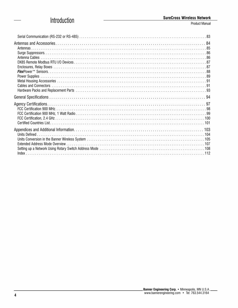
Serial Communication (RS-232 or RS-485) . . . . . . . . . . . . . . . . . . . . . . . . . . . . . . . . . . . . . . . . . . . . . . . . . . . . . . . . . . . . . . . . . . . . . 83
Antennas and Accessories . . . . . . . . . . . . . . . . . . . . . . . . . . . . . . . . . . . . . . . . . . . . . . . . . . . . . . . . . . . . . . . . . . . . . . . . . . 84Antennas . . . . . . . . . . . . . . . . . . . . . . . . . . . . . . . . . . . . . . . . . . . . . . . . . . . . . . . . . . . . . . . . . . . . . . . . . . . . . . . . . . . . . . . . . . . . . . . 85Surge Suppressors. . . . . . . . . . . . . . . . . . . . . . . . . . . . . . . . . . . . . . . . . . . . . . . . . . . . . . . . . . . . . . . . . . . . . . . . . . . . . . . . . . . . . . . . 86Antenna Cables . . . . . . . . . . . . . . . . . . . . . . . . . . . . . . . . . . . . . . . . . . . . . . . . . . . . . . . . . . . . . . . . . . . . . . . . . . . . . . . . . . . . . . . . . . 86DX85 Remote Modbus RTU I/O Devices . . . . . . . . . . . . . . . . . . . . . . . . . . . . . . . . . . . . . . . . . . . . . . . . . . . . . . . . . . . . . . . . . . . . . . . . 87Enclosures, Relay Boxes . . . . . . . . . . . . . . . . . . . . . . . . . . . . . . . . . . . . . . . . . . . . . . . . . . . . . . . . . . . . . . . . . . . . . . . . . . . . . . . . . . . 87FlexPower™ Sensors. . . . . . . . . . . . . . . . . . . . . . . . . . . . . . . . . . . . . . . . . . . . . . . . . . . . . . . . . . . . . . . . . . . . . . . . . . . . . . . . . . . . . . 88Power Supplies . . . . . . . . . . . . . . . . . . . . . . . . . . . . . . . . . . . . . . . . . . . . . . . . . . . . . . . . . . . . . . . . . . . . . . . . . . . . . . . . . . . . . . . . . . 89Metal Housing Accessories . . . . . . . . . . . . . . . . . . . . . . . . . . . . . . . . . . . . . . . . . . . . . . . . . . . . . . . . . . . . . . . . . . . . . . . . . . . . . . . . . 91Cables and Connectors . . . . . . . . . . . . . . . . . . . . . . . . . . . . . . . . . . . . . . . . . . . . . . . . . . . . . . . . . . . . . . . . . . . . . . . . . . . . . . . . . . . . 91Hardware Packs and Replacement Parts . . . . . . . . . . . . . . . . . . . . . . . . . . . . . . . . . . . . . . . . . . . . . . . . . . . . . . . . . . . . . . . . . . . . . . . 93
General Specifications . . . . . . . . . . . . . . . . . . . . . . . . . . . . . . . . . . . . . . . . . . . . . . . . . . . . . . . . . . . . . . . . . . . . . . . . . . . . . 94
Agency Certifications. . . . . . . . . . . . . . . . . . . . . . . . . . . . . . . . . . . . . . . . . . . . . . . . . . . . . . . . . . . . . . . . . . . . . . . . . . . . . . 97FCC Certification 900 MHz . . . . . . . . . . . . . . . . . . . . . . . . . . . . . . . . . . . . . . . . . . . . . . . . . . . . . . . . . . . . . . . . . . . . . . . . . . . . . . . . . . 98FCC Certification 900 MHz, 1 Watt Radio . . . . . . . . . . . . . . . . . . . . . . . . . . . . . . . . . . . . . . . . . . . . . . . . . . . . . . . . . . . . . . . . . . . . . . . 99FCC Certification, 2.4 GHz . . . . . . . . . . . . . . . . . . . . . . . . . . . . . . . . . . . . . . . . . . . . . . . . . . . . . . . . . . . . . . . . . . . . . . . . . . . . . . . . . 100Certified Countries List. . . . . . . . . . . . . . . . . . . . . . . . . . . . . . . . . . . . . . . . . . . . . . . . . . . . . . . . . . . . . . . . . . . . . . . . . . . . . . . . . . . . 101
Appendices and Additional Information. . . . . . . . . . . . . . . . . . . . . . . . . . . . . . . . . . . . . . . . . . . . . . . . . . . . . . . . . . . . . . . . 103Units Defined . . . . . . . . . . . . . . . . . . . . . . . . . . . . . . . . . . . . . . . . . . . . . . . . . . . . . . . . . . . . . . . . . . . . . . . . . . . . . . . . . . . . . . . . . . . 104Units Conversion in the Banner Wireless System . . . . . . . . . . . . . . . . . . . . . . . . . . . . . . . . . . . . . . . . . . . . . . . . . . . . . . . . . . . . . . . . 105Extended Address Mode Overview . . . . . . . . . . . . . . . . . . . . . . . . . . . . . . . . . . . . . . . . . . . . . . . . . . . . . . . . . . . . . . . . . . . . . . . . . . . 107Setting up a Network Using Rotary Switch Address Mode . . . . . . . . . . . . . . . . . . . . . . . . . . . . . . . . . . . . . . . . . . . . . . . . . . . . . . . . . 108Index . . . . . . . . . . . . . . . . . . . . . . . . . . . . . . . . . . . . . . . . . . . . . . . . . . . . . . . . . . . . . . . . . . . . . . . . . . . . . . . . . . . . . . . . . . . . . . . . . 112

5Banner Engineering Corp. • Minneapolis, MN U.S.A.www.bannerengineering.com • Tel: 763.544.3164
SureCross Wireless Network
Product Manual Introduction
Introducing the SureCross™ Wireless SystemThe SureCross™ DX80 wireless I/O network provides reliable monitoring without the burden of wiring or conduit installation and can operate independently or in conjunction with a PLC and/or PC software.
The SureCross NetworkThe SureCross DX80 network is a deterministic system—the network identifies when the radio signal is lost and drives relevant outputs to user-defined conditions. Once the radio signal is reacquired, the network returns to normal operation.
Each wireless network system consists of one Gateway and one or more Nodes that ship with factory defined inputs and outputs. Devices may be all discrete I/O, all analog I/O, mixed discrete and analog I/O, and FlexPower™.
Gateways and NodesA Gateway device acts as the master device within each radio network and initiates communication and reporting with the Nodes. A radio network contains only one Gateway, but can contain many Nodes. Each Node device can be connected to sensors or output devices and reports I/O status to the Gateway. Devices may be all discrete I/O, mixed discrete and analog I/O, or FlexPower™.
GatewayPro and Ethernet BridgeThe DX80 GatewayPro combines, in one DX80 unit, the function of a standard Gateway with the ability to interface to Ethernet using Modbus/TCP or EtherNet/IP™ protocols. The GatewayPro has a serial port as well as an industrial Ethernet port.
To achieve the same functionality with a standard Gateway, add a DX83 Ethernet Bridge to any standard DX80 Gateway device. The DX83 Ethernet Bridge adds the Web page configuration ability to your system as well as the ability to interface to Ethernet using Modbus/TCP or EtherNet/IP protocols. A DX83 Ethernet Bridge connected to a DX80 Gateway functions as a DX80 GatewayPro while allowing the Gateway to have I/O points.
Host SystemsHost-connected systems can contain up to 15 Nodes (Rotary Switch addressing) or 48 Nodes (extended addressing mode) within a single network and may be all discrete, all analog, or a mix of discrete and analog I/O. Host-connected systems allow for logic and calculations to be applied to the I/O. Inputs from Nodes within the network are transmitted to the Gateway, which communicates the information to a host device for processing. While the Gateway is the master device within the radio network, the Gateway may be a slave to the Modbus network.
FlexPowerBanner’s FlexPower technology allows for a true wireless solution by allowing the device to operate using either 10 to 30V dc, 3.6V lithium D cell batteries, or solar power. This unique power management system can operate a FlexPower Node and an optimized sensing device for up to five years on a single lithium D cell.
EtherNet/IP™ is a trademark of ControlNet International, Ltd and Open DeviceNet Vendor Association, Inc (ODVA).

6
Banner Engineering Corp. • Minneapolis, MN U.S.A.www.bannerengineering.com • Tel: 763.544.3164
SureCross Wireless Network Product ManualIntroduction
FeaturesDX80 Gateway and Node
1. Port, NPT Gland, or Plug If unused, install the provided plug into the 1/2 NPT threaded port. Refer to the Installation section if an IP67 seal is required.
2. Rotary Switch 1 (left) Sets the Network ID (NID) to a hexidecimal value from 0 to F, for a total of 16 Network IDs. A Gateway and its corresponding Nodes must be assigned the same Network ID.
Rotary Switch 2 (right) Gateway: Sets the Gateway’s LCD viewing device address. The Gateway is predefined as Device Address 0. Node: Sets the Node’s Device Address (hexidecimal 1 to F). Each Node within a network must have a unique Node Device Address.
3. Push Button 1 Single-click to advance across all top-level DX80 menus.Single-click to move down interactive menus, once a top-level menu is chosen.
4. Push Button 2 Double-click to select a menu and to enter manual scrolling mode. Double-click to move up one level at a time.
5. LED 1 and 2 Provide real-time feedback to the user regarding RF link status, serial communications activity, and the error state.
6. LCD Display Six-character display provides run mode user information and shows enabled I/O point status. This display allows the user to conduct a Site Survey (RSSI) and modify other DX80 configuration parameters without the use of a PC or other external software interfaces. On the Node, after 15 minutes of inactivity, the LCD goes blank. Press any button to refresh the display.
7. 5-Pin M12 Euro-style quick-disconnect serial port
1
2
3
4
5
6
7

7Banner Engineering Corp. • Minneapolis, MN U.S.A.www.bannerengineering.com • Tel: 763.544.3164
SureCross Wireless Network
Product Manual Introduction
DX80 GatewayPro
1. Industrial Ethernet Port, female
2. Rotary Switch 1 (left) Sets the Network ID (NID) to a hexidecimal value from 0 to F, for a total of 16 Network IDs. A Gateway and its corresponding Nodes must be assigned the same Network ID.
Rotary Switch 2 (right) Gateway: Sets the Gateway’s LCD viewing device address. The Gateway is predefined as Device Address 0. Node: Sets the Node’s Device Address (hexidecimal 1 to F). Each Node within a network must have a unique Node Device Address.
3. Push Button 1 Single-click to advance across all top-level DX80 menus. Single-click to move down interactive menus, once a top-level menu is chosen.
4. Push Button 2 Double-click to select a menu and to enter manual scrolling mode. Double-click to move up one level at a time.
5. LED 1 and 2 Provide real-time feedback to the user regarding RF link status, serial communications activity, and the error state.
6. LCD Display Six-character display provides run mode user information. This display allows the user to conduct a Site Survey (RSSI) and modify other DX80 configuration parameters without the use of a PC or other external software interfaces. On the Node, after 15 minutes of inactivity, the LCD goes blank. Press any button to refresh the display.
7. 5-Pin M12 Euro-style quick-disconnect serial port
1
2
3
4
5
6
7

8
Banner Engineering Corp. • Minneapolis, MN U.S.A.www.bannerengineering.com • Tel: 763.544.3164
SureCross Wireless Network Product ManualIntroduction
DX83 Ethernet Bridge
1. Industrial Ethernet Port, female
2. Housing The rugged, industrial DX80 housing meets IEC IP67 standards.
3. Mounting Hole, #10/M5 Clearance
Mounting Holes accept metric M5 or UNC/UNF #10 hardware -- DIN rail mount adapter bracket available.
4. 5-Pin M12 Euro-style quick-disconnect serial port
1
2
3
4
DX80 Gateway and Node Wiring Chamber
1. Housing The rugged, industrial DX80 housing meets IEC IP67 standards.
2. Mounting Hole, #10/M5 Clearance Mounting Holes accept metric M5 or UNC/UNF #10 hardware -- DIN rail mount adapter bracket available.
3. Wiring Terminal Strip The 16 spring-clip type wiring terminals accept wire sizes: AWG 12-28 or 2.5 mm2
4. Port, PG-7 Gland or Blank The PG-7 threaded ports can accept provided cable glands or blanks.
5. Ribbon Connector Ribbon cable connects wiring base to LCD/radio.
The GatewayPro has no serviceable parts inside the housing and no wiring chamber. During setup or standard operation, there should not be a need to open the GatewayPro.
1
2
3
4
5
9Banner Engineering Corp. • Minneapolis, MN U.S.A.www.bannerengineering.com • Tel: 763.544.3164
SureCross Wireless Network
Product Manual Introduction
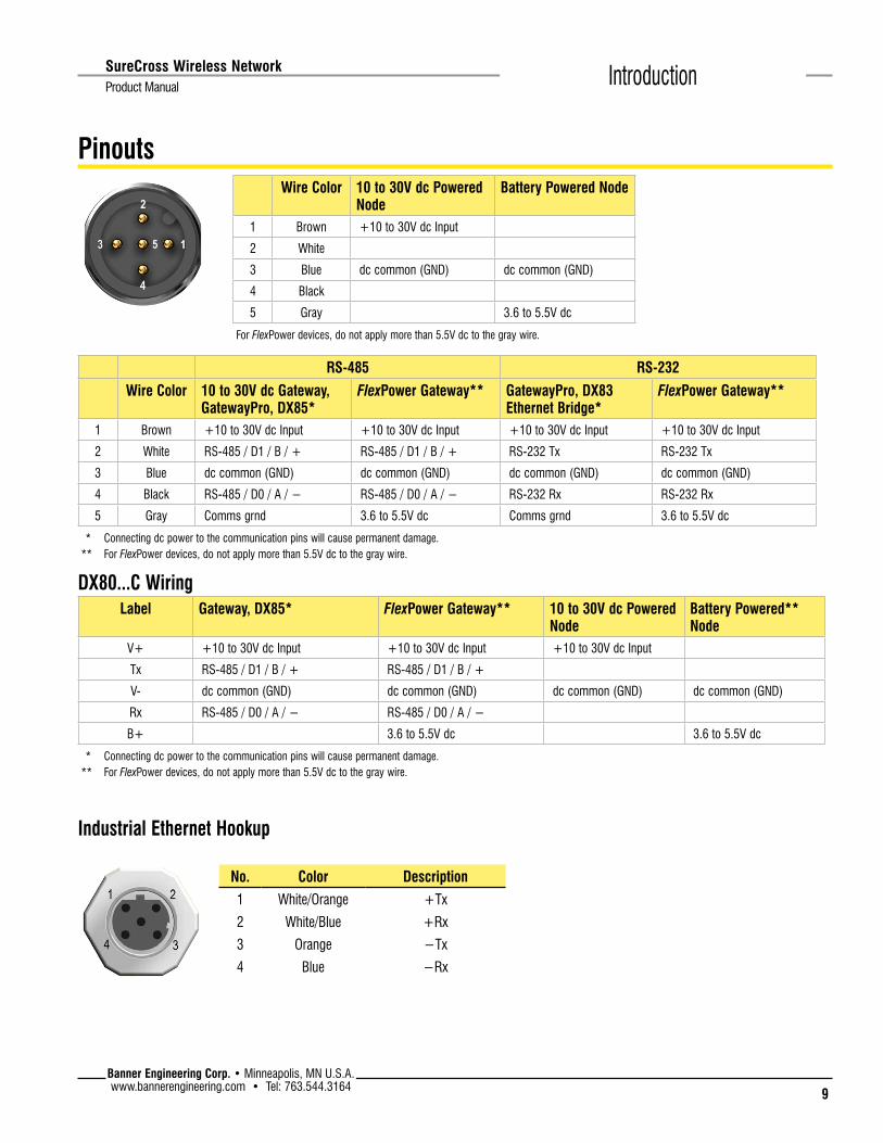
Pinouts
RS-485 RS-232
Wire Color 10 to 30V dc Gateway, GatewayPro, DX85*
FlexPower Gateway** GatewayPro, DX83 Ethernet Bridge*
FlexPower Gateway**
1 Brown +10 to 30V dc Input +10 to 30V dc Input +10 to 30V dc Input +10 to 30V dc Input
2 White RS-485 / D1 / B / + RS-485 / D1 / B / + RS-232 Tx RS-232 Tx
3 Blue dc common (GND) dc common (GND) dc common (GND) dc common (GND)
4 Black RS-485 / D0 / A / − RS-485 / D0 / A / − RS-232 Rx RS-232 Rx
5 Gray Comms grnd 3.6 to 5.5V dc Comms grnd 3.6 to 5.5V dc
* Connecting dc power to the communication pins will cause permanent damage. ** For FlexPower devices, do not apply more than 5.5V dc to the gray wire.
Wire Color 10 to 30V dc Powered Node
Battery Powered Node
1 Brown +10 to 30V dc Input
2 White
3 Blue dc common (GND) dc common (GND)
4 Black
5 Gray 3.6 to 5.5V dc
For FlexPower devices, do not apply more than 5.5V dc to the gray wire.
DX80...C WiringLabel Gateway, DX85* FlexPower Gateway** 10 to 30V dc Powered
NodeBattery Powered** Node
V+ +10 to 30V dc Input +10 to 30V dc Input +10 to 30V dc Input
Tx RS-485 / D1 / B / + RS-485 / D1 / B / +
V- dc common (GND) dc common (GND) dc common (GND) dc common (GND)
Rx RS-485 / D0 / A / − RS-485 / D0 / A / −
B+ 3.6 to 5.5V dc 3.6 to 5.5V dc
* Connecting dc power to the communication pins will cause permanent damage. ** For FlexPower devices, do not apply more than 5.5V dc to the gray wire.
No. Color Description1 White/Orange +Tx
2 White/Blue +Rx
3 Orange −Tx
4 Blue −Rx
Industrial Ethernet Hookup

10
Banner Engineering Corp. • Minneapolis, MN U.S.A.www.bannerengineering.com • Tel: 763.544.3164
SureCross Wireless Network Product ManualIntroduction
DimensionsDX80 Gateway and Node
65.0[2.56”]
65.0[2.56”]
80.3[3.16”]
80.8[3.18”]
60[2.36”]
120[4.72”]
127[5”]
19[0.75”]
30.65[1.21”]
22.2[0.875”]
7.9[0.31”]
7.65[0.30”]
14.67[0.578”]

11Banner Engineering Corp. • Minneapolis, MN U.S.A.www.bannerengineering.com • Tel: 763.544.3164
SureCross Wireless Network
Product Manual Introduction
DX80 GatewayPro
65.0[2.56’’]
65.0[2.56’’]
80.3[3.16’’]
80.8[3.18’’]
60[2.36’’]
136[5.35’’]
7.9[0.31’’]
7.65[0.30’’]
14.67[0.578’’]

12
Banner Engineering Corp. • Minneapolis, MN U.S.A.www.bannerengineering.com • Tel: 763.544.3164
SureCross Wireless Network Product ManualIntroduction
DX83 Ethernet Bridge
65.0[2.56’’]
7.9[0.31’’]
80.3[3.16’’]
65.0[2.56’’]
7.65[0.30’’]
60.0[2.36’’]
14.67[0.578’’]
80.8[3.18’’]
136[5.35’’]

13Banner Engineering Corp. • Minneapolis, MN U.S.A.www.bannerengineering.com • Tel: 763.544.3164
SureCross Wireless Network
Product Manual Introduction
Menu StructureDX80 Gateway and GatewayPro Setup MenuWhen power is applied, the DX80 begins running. The display screen auto loops through the RUN menu and communication begins between the Gateway and Node(s). Auto looping through the RUN menu is the normal operating mode for all devices on the wireless network.
From the RUN Menu (or any menu), single-click button 1 to advance through the top-level menus. The device auto display loops through the menu options if either of the RUN, DINFO, or FCTRY menus are selected. If the device is paused on the SITE, DVCFG, or DERR menu options, the display does not auto loop.
To enter manual scrolling mode, double-click button 2 at the top level menu. Use the instructions shown in the chart below to navigate the menu system. To return to the top level menus and auto display loop mode, double-click button 2 twice.
NOD XX
M XX
R XX
Y XX
G XX
*DINFO *FCTRY *SITE *DVCFG *DERR*RUN
AUTODISPLAY
LOOP
AUTODISPLAY
LOOP
AUTODISPLAY
LOOP
(DEV)
GATEWY
(NID)
XX
(SLID)
XX
(BAUD)
XX
(PRTY)
XX
(DEV)
GATEWY
(RADIO
MICRO)
V 00.0 A
(LCD
MICRO)
V 00.0 A
(DX80
S/N)
(0000)
(DX80
MODEL)
(0000-00)
(PROD
DATE)
(00-00)
Single-clickButton 2
Single-clickButton 2
Single-clickButton 2
Double-clickButton 2
adjust right rotaryswitch to survey the
selected Node
Single-clickButton 2
Dou
ble-
clic
kB
utto
n 2
Dou
ble-
clic
k B
utto
n 2
NOD XX
EC XX CLEAR
ERR
ERASED
ERR
DISABL
*ERROR
DISABL IGNORE
NextDevice
Single-click Button 1 to advance through menu
AUTODISPLAY
LOOP
Single-clickButton 2
Single-clickButton 2
Single-clickButton 2
Single-clickButton 2
Single-clickButton 2
Single-clickButton 2
New ErrorDetected
adjust the rotaryswitches to surveythe selected Node
(DEV)
I/O XX
GATEWY
NID XX
ON/OFF
(DEV)
I/O XX
GATEWY
NID XX
ON/OFF
Even
None
Odd
Single-clickButton 2
Single-clickButton 2
SAVESDISPLAYED
VALUE
Sing
le-c
lick
B1
19200
9600
38400
Single-clickButton 2
Single-clickButton 2
SAVESDISPLAYED
VALUE
NEW XX
Single-clickButton 2
Single-clickButton 2
adjust rotary switchesto set the network ID
SAVES NEWVALUES
CUR XX
Single-clickButton 2
Single-clickButton 2
adjust rotary switchesto set slave ID, usingbutton 1 to select the
digits
SAVES NEWVALUES
(NID) (SLID) (BAUD) (PRTY)Network ID Slave ID Baud Rate Parity
Sing
le-c
lick
B1
NEW XX
Single-clickButton 1
Single-clickButton 1
Single-clickButton 1
Single-clickButton 1
Single-click Button 1 to advance through menu
(NAME)
XXXXXX
XXXXXX
Single-click Button 1 to advance through menu
CUR XX
Dou
ble-
clic
k B
utto
n 2
Dou
ble-
clic
kB
utto
n 2
* Set to 000000 to use the serial number.
Device Info Factory Info Site Survey Device Config Device Error
16
8
32
Single-clickButton 2
Single-clickButton 2
SAVESDISPLAYED
VALUE
Sing
le-c
lick
B1
(MAXN)Timing
48
MANUAL
AUTOAUTO
SET
Single-clickButton 2
Single-clickButton 2
Sing
le-c
lick
B1
(XADR)Extended Addressing
XADR
ADJUST ROTARYSWITCH TOSET XADR
Single-clickButton 2
XXXXXX
Sing
le-c
lick
B1
Single-clickButton 2
CONFRM
XADR
XXXXX
NETWRK
Single-click
Button 2
BINDNG
Single-clickButton 1 or 2
Reboot
SAVED
*
XXXXXX
The Network ID (NID) can be set at any time using the rotary switches. Once changed, allow five seconds for the devices to update to the new NID.
Navigating the menu: * indicates a top level menu option ( ) indicates a sub-menu item No characters indicate the value of the previous item
The MAXN and XADR menus are only available in extended addressing mode. To access extended addressing mode, move DIP switch 1 to the ON position. To manually select the serial number, use button 1 to move across the digits and use the right rotary switch to select the value used as the device serial number.

14
Banner Engineering Corp. • Minneapolis, MN U.S.A.www.bannerengineering.com • Tel: 763.544.3164
SureCross Wireless Network Product ManualIntroduction
DX80 Node Setup MenusWhen power is applied, the DX80 begins running. The display screen auto loops through the RUN menu and communication begins between the Gateway and Node(s). Auto looping through the RUN menu is the normal operating mode for all devices on the wireless network.
From the RUN Menu (or any menu), single-click button 1 to advance through the top-level menus. The device auto display loops through the menu options if either of the RUN, DINFO, or FCTRY menus are selected. If the device is paused on the DVCFG or DERR menu options, the display does not auto display loop.
To enter manual scrolling mode, double-click button 2 at the top level menu. Use the instructions shown in the chart below to navigate the menu system. To return to the top level menus and auto display loop mode, double-click button 2 twice.
*DINFO*RUN *FCTRY *DVCFG *DERR
AUTODISPLAY
LOOP
AUTODISPLAY
LOOP
AUTODISPLAY
LOOP
(DEV)
NOD XX
(NAME)
NODE XX
KIT
XXXXX
(NID)
XX
(DEV)
NOD XX
(RADIO
MICRO)
V 00.0 A
(DX80
S/N)
0x0000(2)
(LCD
MICRO)
0x0000(2)
(PROD
DATE)
(00-00)
Single-clickButton 2
NEW XX
Single-clickButton 2
Single-clickButton 2
SAVES NEWVALUES
(NID)Network ID
Single-clickButton 2
Dou
ble-
clic
k B
tn 2
NEW XX
Single-clickButton 2
Single-clickButton 2
SAVES NEWVALUES
(NADR)Node Address
NOD XX
**EC XX IGNORE
*ERROR
Single-click Button 1
** LCD will display ‘NO ERR’ if no error is detected.
Single-clickButton 2
Single-clickButton 2
New ErrorDetected
Sing
le-c
lick
But
ton
2
OFF Press and hold Button 1 from any top level menu to power down the Node.Press and hold Button 1 from power down mode to enter RUN mode.
ADJUST LEFTROTARY SWITCH
TO SETNETWORK ID
ADJUST RIGHTROTARY SWITCH
TO SETNODE ADDRESS
(DEV)
I/O XX
NOD XX
NID XX
ON/OFF
Single-clickButton 1
Single-clickButton 1
Single-clickButton 1
(DX80
MODEL)
0x0000(2)
0.00
Single-click Button 1 to advance through menu
MANUAL
AUTO
SET
Single-clickButton 2
Sing
le-c
lick
B1
(XADR)Extended Addressing
XADR
Adjust rotary switchto set XADR
Single-clickButton 2
XXXXXXSing
le-c
lick
B1
CONFRM
XADR
XXXXX
NETWRK
Single-click
Button 2
BINDNG
Single-clickButton 1 or 2
Reboot
Dou
ble-
clic
kB
utto
n 2
BOUND
Device Info Factory #s Device Config. Device Error
Single-clickButton 2
PRIOR
NADR
XX
NEW
NADR
XX
CONFRM
NADR
XX
Single-click Button 1 to advance through menu
Navigating the menu: * indicates a top level menu option ( ) indicates a sub-menu item No characters indicate the value of the previous item
Node LCD Timeout: After 15 minutes of inactivity, the LCD screen stops displaying information. Press any button to refresh the display if the Node has entered this energy-saving mode.
The Network ID (NID) and Node Address (NADR) can be set at any time from the rotary switches. The left rotary switch sets the Network ID and the right rotary switch sets the Node Address.
The MAXN and XADR menus are only available in extended addressing mode. To access extended addressing mode, move DIP switch 1 to the ON position. To manually select the serial number, use button 1 to move across the digits and use the right rotary switch to select the value used as the device serial number.

15Banner Engineering Corp. • Minneapolis, MN U.S.A.www.bannerengineering.com • Tel: 763.544.3164
SureCross Wireless Network
Product Manual Introduction
RUNThe RUN menu displays the Network ID, device name, and the I/O values of the device. On a Gateway, the I/O displayed may be the I/O of the Gateway or of a selected Node, which is determined by the position of the rotary switches.
DINFO (Device Information)The Device Info menu displays the device-specific information, such as the device name, the Network ID, Slave ID, baud rate, and parity. When in extended address mode, the DINFO menu also displays the maximum Node setting and the extended addressing binding code used to form the network.
FCTRY (Factory)The FCTRY menu displays the version numbers of various components within the device, including the radio micro number, the LCD number, the device’s serial number, the device’s model number, and the production date.
SITE (Site Survey)Access the SITE menu to see the results of a Site Survey conducted with this Gateway. The SITE menu displays the device number of the Node the Site Survey was conducted with as well as the missed, green, yellow, and red received packet count. For more information on determining what these values represent, refer to the Site Survey chapter of this manual.
The SITE menu is only available on the Gateways.
DVCFG (Device Configuration)On Gateways, the DVCFG menu allows users to set various device-specific parameters, including the Network ID, Slave ID, baud rate, and parity. When in extended address mode, use this menu to set the maximum number of Nodes within the network and the extended address binding code.
On Nodes, use the DVCFG to set the network ID, Node address (also referred to as a device address), and extended address binding code.
DERR (Device Error)On the GatewayUse the DERR menu to clear, disable, or ignore error messages generated by devices within the network. The Node number that generated the error and the error code (EC) display onscreen. Single-click button 1 to advance through the menu of CLEAR (clear this particular instance of the error from the system), DISABL (disable this particular error from appearing from this specific Node), and IGNORE (ignore this error but do not remove it from the system).
After the error messages for a Node are cleared, disabled, or ignored, errors for any additional Nodes display on the Gateway’s LCD.
On the NodeUse the DERR menu to view and ignore error messages for that Node.

16
Banner Engineering Corp. • Minneapolis, MN U.S.A.www.bannerengineering.com • Tel: 763.544.3164
SureCross Wireless Network Product ManualBasic Setup
Setting Up Your Wireless Network
Step 1: Use Extended Address ModeExtended address mode assigns a unique code, the extended address code, to all devices in a particular network, thereby controlling which radios can exchange information.
Using extended address mode isolates networks from one another by assigning a unique code, the extended address code, to all devices in a particular network. Only devices sharing the extended address code can exchange data. In addition to isolating networks, using extended addressing mode allows you to use up to 47 Nodes with a single Gateway. Without extended addressing, only 15 Nodes can communicate with a single Gateway.
The extended address in the Gateway defaults to a code derived from its serial number although the code can be customized using the manual binding procedure. Binding DX80 devices “locks” Nodes to a specific Gateway by teaching the Nodes the Gateway’s extended address code. After the devices are bound, the Nodes only accept data from the Gateway to which they are bound.
Note: All SureCross Performance Gateways and Nodes are preconfigured for extended addressing mode and cannot use rotary dial address mode. Skip this step in the installation procedure for all Performance products.
For all other SureCross DX80 models, follow these steps to activate extended address mode. After making any changes to DIP switch settings, you must cycle power to the device or the DIP switch changes will not be recognized.
1. Disconnect the Gateway and its Nodes* from their power source.2. Remove the top covers of all radios.3. Move DIP switch 1 to the ON position. (Refer to the Device Configuration
section of the device’s data sheet for instructions on accessing the DIP switches.)
4. Apply power to the radios.* To cycle power to devices with batteries integrated into the housing, remove the battery for one minute.
Mixing Performance and Non-Performance Radios in the Same NetworkTo comply with federal regulations, the 150 mW radios and 1 Watt radios communicate differently. To mix Performance radios with non-Performance radios:
• Performance radios must operate in 250 mW mode, not 1 Watt mode (DIP switch 1 ON)• Non-Performance radios must be set to use Extended Address Mode (DIP switch 1 ON)
For more detailed instructions about setting up your wireless network, refer to the Quick Start Guide, Banner document number 128185.
For more information about using Performance and non-Performance radios within the same network, refer the technical note titled Mixing Performance Radios and 150 mW Radios in the Same Network listed on the FAQ/Knowledgebase section of Banner's Wireless Sensor Networks website.

17Banner Engineering Corp. • Minneapolis, MN U.S.A.www.bannerengineering.com • Tel: 763.544.3164
SureCross Wireless Network
Product Manual Basic Setup
Step 2: Apply Power1. Apply power to the Gateway by connecting the 10-30V dc cable as shown in the wiring diagram.
The Gateway begins in *RUN mode, displays the current network ID (NID), then identifies itself as a Gateway.
2. Apply power to the Node by connecting the 10-30V dc cable or the DX81 Battery Supply Module as shown.The Node starts in *RUN mode, displays the current network ID, then identifies itself as a Node and lists the device ID. Once running, the Node begins displays its I/O points.
Wire Color 10 to 30V dc Powered Node
Battery Powered Node
1 Brown +10 to 30V dc Input
2 White
3 Blue dc common (GND) dc common (GND)
4 Black
5 Gray 3.6 to 5.5V dc
For FlexPower devices, do not apply more than 5.5V dc to the gray wire.
RS-485 RS-232
Wire Color 10 to 30V dc Gateway, GatewayPro, DX85*
FlexPower Gateway** GatewayPro, DX83 Ethernet Bridge*
FlexPower Gateway**
1 Brown +10 to 30V dc Input +10 to 30V dc Input +10 to 30V dc Input +10 to 30V dc Input
2 White RS-485 / D1 / B / + RS-485 / D1 / B / + RS-232 Tx RS-232 Tx
3 Blue dc common (GND) dc common (GND) dc common (GND) dc common (GND)
4 Black RS-485 / D0 / A / − RS-485 / D0 / A / − RS-232 Rx RS-232 Rx
5 Gray Comms grnd 3.6 to 5.5V dc Comms grnd 3.6 to 5.5V dc
* Connecting dc power to the communication pins will cause permanent damage. ** For FlexPower devices, do not apply more than 5.5V dc to the gray wire.
Step 3: Binding the Gateway and NodesBinding Nodes to their Gateway ensures the Nodes only exchange data with the Gateway they are bound to. The Gateway automatically generates a unique extended addressing, or binding, code when the Gateway enters binding mode. This code is then transmitted to all radios within range that are also in binding mode. After a Node is bound, the Node accepts data only from the Gateway to which it is bound. The extended addressing (binding) code defines the network, and all radios within a network must use the same code.
After binding your Nodes to the Gateway, make note of the binding code displayed under the *DVCFG menu, XADR submenu on the LCD. Knowing the binding code prevents having to re-bind all Nodes if your Gateway is ever replaced.
To automatically bind the Gateway and its Node(s), follow these steps:
On the GatewayStep 1. Disconnect the Gateway from its power source. Step 2. Remove the Gateway’s top cover.Step 3. Move DIP switch 1 to the ON position to activate Extended Addressing Mode.Step 4. Apply power to the Gateway. The LCD shows POWER, then *RUN.Step 5.
18
Banner Engineering Corp. • Minneapolis, MN U.S.A.www.bannerengineering.com • Tel: 763.544.3164
SureCross Wireless Network Product ManualBasic Setup
Next Steps: Conducting a Site Survey and Installing your devices.
If your Gateway has buttons OR If your Gateway does not have buttons
Triple click button 2 to enter binding mode. The red LEDs flash alternately when the Gateway is in binding mode. Any Node entering binding mode will bind to this Gateway. The LCD shows NETWRK BINDNG.
Remove the rotary dial access cover and set both the right and left rotary dials to 0, then set both the right and left rotary dials to F.
Note that both rotary dials must be changed to F after applying power, not before applying power.
On the NodeStep 6. Disconnect the Node from its power source. For Nodes powered by a battery integrated into the housing, remove the battery for at least one minute. Step 7. Remove the Node’s top cover.Step 8. Move DIP switch 1 to the ON position to activate Extended Addressing Mode.Step 9. Apply power to the NODE. The LCD shows POWER, then *RUN.Step 10.
If your Node has buttons OR If your Node has no buttons or is a round M-GAGE
Triple click button 2 to enter binding mode.The Node enters binding mode and locates the Gateway that is also in binding mode. While the Node in binding, the LCD shows NETWRK BINDNG. When the Node is bound, the LEDs are both solid red for a few seconds. The Node cycles its power, then entering RUN mode. The LCD shows BOUND, then *RUN.
Remove the top cover and set both the left and right rotary dials to F to enter binding mode.
The Node enters binding mode and searches for the Gateway in binding mode. When searching for the Gateway, the LED flashes red and green alternately.
When the Node finds the Gateway and is bound, the LED is red and green for four seconds (looks orange), then the red and green flash simultaneously (looks orange) four times. The Node automatically exits binding mode.
Step 11. Use both of the Node’s rotary dials to assign a decimal Node address (device ID) between 01 and 48.* The left rotary dial represents the tens digit (0-4) and the right dial represents the ones digit (0-9) of the Node address (device ID).Step 12. Repeat steps 6 through 11 for each additional Node that needs to communicate to that Gateway.
On the GatewayIf your Gateway has buttons OR If your Gateway does not have buttons
Single click either button 1 or button 2 on the Gateway to exiting binding mode and reboot the Gateway.
Change the Gateway’s rotary dials to a valid Network ID.
Valid Network IDs are 01 through 32, in decimal, established using both rotary dials. The left dial may be set to 0, 1, 2, or 3. The right dial may be set from 0 to 9 when the left dial is at 0, 1, or 2; or set to 0 through 2 when the left dial is at 3. (Positions A through F are invalid network ID numbers.)
Additional NotesTo cycle power to devices with batteries integrated into the housing, remove the battery for one minute. After making any changes to DIP switch settings, you must cycle power to the device or the DIP switch changes will not be recognized.
When installing special kits with pre-mapped I/O, indicated by device model numbers beginning in DX80K, return the rotary dials to their original positions after binding. If the rotary dials are not returned to their original positions, the I/O mapping will not work.

19Banner Engineering Corp. • Minneapolis, MN U.S.A.www.bannerengineering.com • Tel: 763.544.3164
SureCross Wireless Network
Product Manual Basic Setup
Step 4: Verify CommunicationsOn the GatewayVerify LED 1 is on and green.
On the NodeVerify LED 1 is flashing green and LED 2 is off. Until communication is established with the Gateway, the Node’s LED 2 flashes red. When communication is established, the Node’s LED 1 flashes green.
A Node will not sample its inputs until it is in sync with a Gateway.
LED 1 LED 2 Gateway Status Node Status
Green ON — Power ON
Green flash (1 per sec) RF Link Ok
— Yellow Flash Modbus Communication Active
— Red Flash Modbus Communication Error
Red Flash Red Flash System Error System Error
Red flash (1 per 3 secs) RF Link Error
When testing the Gateway and Node before installation, verify the Gateway and Node are at least two meters apart or the communications may fail.

20
Banner Engineering Corp. • Minneapolis, MN U.S.A.www.bannerengineering.com • Tel: 763.544.3164
SureCross Wireless Network Product ManualSite Survey
Site SurveyConducting a Site Survey analyzes the radio communications link between the Gateway and any Node within the network by reporting the number of missed and received data packets. Perform the Site Survey before permanently installing the radio network to ensure reliable communication.
Activate Site Survey mode from either the Gateway buttons or the Gateway Modbus holding register 15. Only the Gateway can initiate a Site Survey, and the Site Survey analyzes the radio communications link with one Node at a time.
Gateway
Node
formerly known as 133602 rev D
This document is now part of the SureCross DX80 Wireless I/O Network Manual, Banner part number 132607. These pages are extracted directly from the manual and no longer list the 6-digit part number specific to the original, standalone reference guide.

21Banner Engineering Corp. • Minneapolis, MN U.S.A.www.bannerengineering.com • Tel: 763.544.3164
SureCross Wireless Network
Product Manual Site Survey
Site Survey from the Menu SystemUse the Gateway to initiate a site survey analysis. Follow these steps to initiate a Site Survey using the Gateway’s buttons and menu system.
On the Gateway1. Remove the rotary switch access cover.2. To check the status of Node 1, change the Gateway’s right rotary switch setting to 1.
The Gateway is now enabled to read the status of Node 1; the display scrolls through the Node’s I/O status.
3. Single-click button 1 to scroll across the menu levels until reaching the Site Survey (*SITE) menu. 4. Single-click button 2 to enter the Site Survey menu.5. Single-click button 2 to begin conducting a Site Survey with the Node selected in step 2.
The Gateway analyzes the quality of the signal from the selected Node by counting the number of data packets it receives from the Node.
6. Examine reception readings (M, R, Y, G) of the Gateway at various locations. Note that the numbers displayed are a percentage. M displays the percent of missed packets while R, Y, and G display the percentage of received packets at a given signal strength.M = Percentage of missed packets R = RED marginal signal Y = YELLOW good signal G = GREEN excellent signal
7. To end the Site Survey, double-click button 2.8. Change the right rotary switch back to 0 (Gateway).
The LCD displays the device readings for the Gateway.
9. Double-click button 2 to move back to the top level menu.10. Single-click button 1 to return to RUN mode.11. Install the rotary switch access cover, referring to the Installation section of the manual to create an IP67 seal.

22
Banner Engineering Corp. • Minneapolis, MN U.S.A.www.bannerengineering.com • Tel: 763.544.3164
SureCross Wireless Network Product ManualSite Survey
Site Survey from Modbus CommandsAll DX80 models reserve the Modbus register I/O 15 (write only) for control messages. The control message code for the Site Survey command is listed below.
To start a Site Survey using a Modbus write holding register command, send a control code of 32 (0x20) and the Node number 1–15 (0x01 to 0x0F) to the Gateway Modbus holding register for I/O 15.
Modbus RegisterI/O 15 Control Code Data Field
I/O 15 Control Messages
Control Code Data Field Restrictions Description32 Node # 1–15 Gateway Only Enable Site Survey between Gateway and Node defined by the data field. All error messages from
the Gateway are ignored when running Site Survey. Only one Node can participate in Site Survey at any given time. To disable the Site Survey, use control code 0x20 with Node 0. A Node must be enabled to run the Site Survey, then disabled before selecting the next Node.
Example CommandI/O 15 32 02
When Site Survey runs, the accumulated results are stored in the Gateway’s I/O 7 and I/O 8 holding registers. The LEDs on the both the Gateway and the Node’s front panel display the signal strength for the wireless RF link. The quality of the communications link is indicated by:
• LED 1 – Green = excellent signal strength• LED 2 – Yellow = good signal strength• LED 1 – Red = poor signal strength
The signal strength is the transmitted signal strength relative to the ambient RF signal present in a specific location, or noise floor.
The Gateway device also displays the Site Survey results on the LCD. For one transmit and receive interval, the Gateway saves the lowest signal strength. The LCD and Modbus registers contain the results of the last 100 samples. The totals are a running tally of the last 100 samples and are continuously updated. Four categories are displayed: • M = Missed packet • Y = Yellow – good signal strength • R = Red – poor signal strength • G = Green – excellent signal strength.To disable Site Survey, send a control code of 32 (0x20) and a Node number of 0 (0x0).
Site Survey Data HoldingWith Site Survey active, Modbus registers I/O 7 and 8 are Site Survey data holding registers that store the accumulated Site Survey results. Error collections in holding register 8 are saved when Site Survey runs and restored after Site Survey is disabled.
Modbus Register
15 14 13 12 11 10 9 8 7 6 5 4 3 2 1 0I/O 7 Red Total Missed Total
I/O 8 Green Total Yellow Total
Example ResultsI/O 7 10 0
I/O 8 80 10
Note: This is the current register arrangement when using Modbus/TCP or Modbus RTU. In some older models, the Modbus/TCP registers are reversed (missed and yellow totals are in bits [8:15], red and green totals are in bits [0:7]).

23Banner Engineering Corp. • Minneapolis, MN U.S.A.www.bannerengineering.com • Tel: 763.544.3164
SureCross Wireless Network
Product Manual Site Survey
Interpreting the Site Survey ResultsSite Survey results are listed as a percentage of data packets received and indicate the signal strength of the received signal.
Result DescriptionGreen Packets received at a strong signal strength. A strong signal
strength is greater than −90 dBm at the receiver.
Yellow Packets received at a good signal strength. A good signal is between −90 and −100 dBm at the receiver.
Red Packets received at a weak signal strength. A weak signal is less than −100 dBm at the receiver.
Missed Packets not received.
Judging if the reliability of a network’s signal meets the needs of the application is not simply a matter of green, yellow, and red packets received. In normal operating mode, when data packets are not received, the transmitter re-sends the packet until the data is received.
For slow monitoring applications such as a tank farm, where data is required in terms of seconds or minutes, receiving most of the data in the ‘red’ range, indicating a weak but reliable signal, transmits enough data for accurate monitoring. Nodes positioned near the outside range of the Gateway’s radio signal may have 90% of the data packets received in the red zone, again indicating a weak, but reliable signal.
A good rule of thumb is to keep the missed packets average to less than 40%. When the network misses more than 40% of the data packets, the signal is usually too unreliable or obstacles may be interfering with the signal. When Site Survey reports the missed packets are 40% or higher, improve the radio system performance by:
• Mounting the network’s antennas higher, • Using higher gain antennas, or• Adding data radios to the network.
Mounting the devices’ antennas higher allows the radio signal to clear obstacles in the area and improves the line of sight between SureCross™ devices. Higher gain antennas will focus the energy of the radio signal in a specific direction and extend the signal’s range. Using data radios is another option to consider when trying to extend the range of a radio network. For more information on data radios, please refer to Banner’s white paper on range extension.
TroubleshootingProblem Possible Solution
Marginal Site Survey (RSSI) results
If the distance between devices is greater than about 5,000 meters (3 miles) line-of-sight *OR* objects, such as trees or man-made obstructions, interfere with the path, and the MISSED packet count exceeds 40 per 100 packets, consider the following steps:
• Raise the DX80 units to a higher elevation—either by physically moving the devices or installing the antenna(s) remotely at a higher position.
• Use high-gain antenna(s) such as Yagi and/or Omni (see Accessories).• Decrease the distance between devices.• Use data radios to extend the position of the Gateway relative to the host system.

24
Banner Engineering Corp. • Minneapolis, MN U.S.A.www.bannerengineering.com • Tel: 763.544.3164
SureCross Wireless Network Product ManualInstallation
Installation

25Banner Engineering Corp. • Minneapolis, MN U.S.A.www.bannerengineering.com • Tel: 763.544.3164
SureCross Wireless Network
Product Manual Installation
Ideal Mounting Conditions
Use a Secondary EnclosureFor most outdoor applications, we recommend installing your SureCross devices inside a secondary enclosure. For a list of available enclosures, refer to the Accessories list.
Mounting SureCross Devices Outdoors Without a Secondary EnclosureAvoid Direct Sunlight. To minimize the damaging effects of ultra-violet radiation, avoid mounting any SureCross™ device facing intense direct sunlight.
• Mount within a protective enclosure,• Mount under an overhang or other source of shade,• Install indoors, or• Face the devices north when installing outside.
For harsh outdoor applications, consider installing your SureCross radio inside a secondary enclosure. For a list of available enclosures, refer to the Accessories chapter.
Avoid Collecting Rain. When possible, mount the devices where rain or snow will drain away from the device.
• Mount vertically so that precipitation, dust, and dirt do not accumulate on permeable surfaces.
• Avoid mounting the devices on flat or concave surfaces, especially if the display will be pointing up.
Moisture and Condensation. If condensation is present in any device, add a small desiccant packet to the inside of the radio. To help vent the radios, Banner also sells a vented plug (model number BWA-HW-031) for the 1/2” NPT port of the SureCross radios.
Reduce Chemical Exposure. Before installing any SureCross™ devices in a chemically harsh environment, contact Banner for more information regarding the life-expectancy. Solvents, oxidizing agents, and other chemicals will damage the devices.
Minimize Mechanical StressWhile the SureCross devices are very durable, they are sophisticated electronic devices that are sensitive to shock and excessive loading.
• Avoid mounting the devices to an object that may be shifting or vibrating excessively. High levels of static force or acceleration may damage the housing or electronic components.
• Do not subject the devices to external loads. Do not step on them or use them as handgrips.• Do not allow long lengths of cable to hang from the DX80 glands on the Gateway or Node. Cabling heavier than 100 grams should be
supported instead of allowed to hang from the DX80 housing.It is the user’s responsibility to install the DX80 devices so they will not be subject to overvoltage transients. Always ground the devices in accordance with local, state, or national regulations.
Avoid direct sunlight

26
Banner Engineering Corp. • Minneapolis, MN U.S.A.www.bannerengineering.com • Tel: 763.544.3164
SureCross Wireless Network Product ManualInstallation
Watertight Glands and Plugs
If the Gateway or Node is mounted outdoors or will be exposed to moisture, dirt, or dust, follow these steps to weatherproof the units.
Watertight GlandsTo make the glands watertight:
1. Wrap four to eight passes of polytetrafluoroethylene (PTFE) tape around the threads as close as possible to the hexagonal body of the gland.
2. Manually thread the gland into the housing hole. Never apply more than 5 in-lbf of torque to the gland or its cable clamp nut.*
Note, these instructions apply both to the PG-7 glands and the 1/2” NPT gland.
Weather-Proofing Glands and Plugs
Rotary Switch Access CoverCheck the rotary switch access cover o-ring every time the access cover is removed. Replace the o-ring when it is damaged, discolored, or showing signs of wear. The o-ring should be:
• Seated firmly against the threads without stretching to fit or without bulging loosely, and
• Pushed against the flanged cover.When removing or closing the rotary switch access cover, manually twist the cover into position. Do not allow cross-threading between the cover and the DX80 face.
Once the cover is in place and manually tightened, use a small screwdriver (no longer than five inches total length) as a lever to apply enough torque to bring the rotary switch access cover even with the DX80 cover surface.
Watertight 1/2” NPT PlugSeal the 1/2” NPT port if it is not used. To install a watertight NPT plug:
1. Wrap 12 to 16 passes of PTFE tape evenly across the length of the threads.
2. Manually thread the plug into the housing port until reaching some resistance.
3. Using a 9/16” crescent wrench, turn the plug until all the plug’s threads are engaged by the housing port or until the resistance doubles. Do not overtighten as this will damage the SureCross unit. These threads are tapered and will create a waterproof seal without overtightening.
Watertight PG-7 PlugSeal any unused PG-7 access holes with one of the supplied black plastic plugs. To install a watertight PG-7 plug:
1. Wrap four to eight passes of PTFE tape around the plug’s threads, as close as possible to the flanged surface.
2. Carefully thread the plastic plug into the vacant hole in the DX80 housing and tighten using a slotting screwdriver. Never apply more than 10 in-lbf torque to the plastic plug.
* This is not a lot of torque and is equivalent to the torque generated without using tools. If a wrench is used, apply only very light pressure. Torquing these fittings excessively damages the device.

27Banner Engineering Corp. • Minneapolis, MN U.S.A.www.bannerengineering.com • Tel: 763.544.3164
SureCross Wireless Network
Product Manual Installation
Increase the Height of the DX80 UnitsPosition the external antenna vertically for optimal RF communication. If necessary, consider changing the height of the SureCross radio, or its antenna, to improve reception. For outdoor applications, mounting the antenna on top of a building or pole may help achieve a line-of-sight radio link with the other radios in the network.
Quick Tips
A clear path increases separation range and performance
Collocation IssuesWhen the radio network’s master device is located too close to another radio device, communications between all devices is interrupted. For this reason, do not install a SureCross Gateway device within two meters of another SureCross DX80 Gateway or Node.
Be Aware of Seasonal ChangesWhen conducting the initial Site Survey, the fewest possible missed packets for a given link is better. However, seasonal changes may affect the signal strength and the total signal quality. Radios installed outside with 50% missed packets in the winter months may have 80% or more missed packets in the summer when leaves and trees interfere with radio reception.
Create a Clear Communication Path Wireless communication is hindered by radio interference and obstructions in the path between the transmitter and receiver. To achieve the best radio performance, carefully consider the installation locations for the Gateways and Nodes and select locations without obstructions in the path.
For more information about antennas, please refer to the Antenna Basics reference guide, Banner document p/n 132113.
No line of sight
Line of sight
Node
Gateway
During spring and summer, leaves may block more of the radio signal.
A good signal strength in winter doesn’t always mean you’ll get the same signal strength the rest of the year.
NodeGateway
Node
Gateway

28
Banner Engineering Corp. • Minneapolis, MN U.S.A.www.bannerengineering.com • Tel: 763.544.3164
SureCross Wireless Network Product ManualInstallation
Antenna mounted remotely from the radio device
Coaxial cable
Surge suppressor
Ground wire to single-point ground system
Remote Antenna InstallationWhen installing a remote antenna system, always include a lightning arrestor or coaxial surge suppressor in the system. Remote antenna systems installed without surge protection invalidate the Banner warranty of the DX80 family of devices. A remote antenna system is any antenna system where the antenna is not connected directly to the radio and typically use coaxial cable to connect the antenna to the radio.
Surge suppressors should be properly grounded and mounted at ground level near where the cabling enters a building. Install the surge suppressor indoors or inside a weatherproof enclosure to minimize corrosion or component deterioration. For best results, mount the surge suppressor as close to the ground as possible to minimize the length of the ground connection and use a single-point ground system to avoid creating ground loops.
For more detailed information about how antennas work and how to install them, refer to the Antenna Basics chapter.
Always install and properly ground a qualified surge suppressor when installing a remote antenna system. Remote antenna configurations installed without surge suppressors invalidate the Banner Engineering Corp. warranty. Always keep the ground wire as short as possible and make all ground connections to a single-point ground system to ensure no ground loops are created.
I/O IsolationWhen connecting analog and discrete I/O to external equipment such as VFDs (Variable Frequency Drives), it may be appropriate to install interposing relays and/or loop isolation devices to protect the DX80 unit from transients, noise, and ground plane interference originating from devices or the environment. Contact Banner Engineering Corp. for more information.

29Banner Engineering Corp. • Minneapolis, MN U.S.A.www.bannerengineering.com • Tel: 763.544.3164
SureCross Wireless Network
Product Manual Installation
Weatherproofing Remote Antenna InstallationsPrevent water damage to the cable and connections by sealing the connections with rubber splicing tape and electrical tape. To protect the connections, follow these steps.
1. Verify both connections are clean and dry before connecting the antenna cable to the antenna or other cable and hand-tightening.
2. Tightly wrap the entire connection with rubber splicing tape. Begin wrapping the rubber splicing tape one inch away from the connection and continue wrapping until you are one inch past the other end of the connection. Each new round of tape should overlap about half the previous round.
3. Protect the rubber splicing tape from UV damage by tightly wrapping electrical tape on top of the rubber splicing tape. The electrical tape should completely cover the rubber splicing tape and overlap the rubber tape by one inch on each side of the connection.

30
Banner Engineering Corp. • Minneapolis, MN U.S.A.www.bannerengineering.com • Tel: 763.544.3164
SureCross Wireless Network Product ManualAdvanced Setup
Advanced Setup

31Banner Engineering Corp. • Minneapolis, MN U.S.A.www.bannerengineering.com • Tel: 763.544.3164
SureCross Wireless Network
Product Manual Advanced Setup
DX80
1 2
www.bannerengineering.com
GATEWAY
900MHz
Ethernet CommunicationsThe DX80 wireless systems are configured using an Ethernet network connection and a common Web page browser. An Ethernet connection can be established from a DX80 GatewayPro device or a DX83 Ethernet Bridge device serially connected to the DX80 Gateway.
The Ethernet Bridge and GatewayPro each ship with an Ethernet crossover cable. One end of the cable is a RJ45 connector and the other end is an industrial Ethernet connector. This cable is designed to be connected directly to a computer. For a list of the accessories, please refer to the Accessories and Replacements parts section.
For more examples of system layouts, please refer to DX80 System Layouts, Banner document p/n 133601.
Power
Host system
DX80 GatewayPro
Industrial Ethernet Connection
Modbus TCP or EtherNet IP
Ethernet Crossover Cable
DX80
1 2
www.bannerengineering.com
GATEWAYPro
900MHz
Host system
DX80
1 2
www.bannerengineering.com
GATEWAYPro
900MHz
Modbus TCP or EtherNet IP
Ethernet Crossover Cable
Modbus RTU
Splitter cable
DX83 Ethernet Bridge
DX80 Gateway

32
Banner Engineering Corp. • Minneapolis, MN U.S.A.www.bannerengineering.com • Tel: 763.544.3164
SureCross Wireless Network Product ManualAdvanced Setup
Web Page AccessBrowser settings The Web pages are served from the DX83 Ethernet Bridge or DX80 GatewayPro device. Internet browsers such as Internet Explorer, Netscape Navigator, or Mozilla Firefox can access the Web pages.
Set up the browser for a direct connection to the Internet. If you are experiencing problems connecting, verify the browser is not set to use a proxy server (see Appendix A for proxy settings.) Note also that a crossover Ethernet cable is required when connecting directly from a host computer to the DX83 Ethernet Bridge or DX80 GatewayPro.
Network SetupDefault IP address / Host Network Settings:The factory default IP address for the DX83 Ethernet Bridge or DX80 GatewayPro devices is:
192.168.0.1
To change the default IP address, set up the host PC with an IP address different from the Ethernet Bridge or GatewayPro IP addresses.* For example, change the PC host IP address to:
Host IP address: 192.168.0.2
Open a Web browser and log into the Ethernet Bridge or GatewayPro by typing the IP address in the browser location window.
http://192.168.0.1
Enter the following as the user name and password.
User name: system Password: admin
The Web home page for the Ethernet Bridge or GatewayPro displays. To log in, click on any tab at the top of the page.

33Banner Engineering Corp. • Minneapolis, MN U.S.A.www.bannerengineering.com • Tel: 763.544.3164
SureCross Wireless Network
Product Manual Advanced Setup
Changing the IP addressOnce logged into the system, use the page tabs at the top of the page to select the hierarchical path: System > Setup > Network. To change the IP address, type in the new IP address and click the Change IP button. The IP address change activates when the Ethernet Bridge or GatewayPro device reboots (power off, power on.)
IMPORTANT: Verify the new IP address is correct before cycling power to the device. Once the IP address is changed, you must enter in the new IP address to access the Web page-based configuration screens. Write down the new IP address (and any other changed parameters on this screen) or print this page and file for your record.
Communication ProtocolBy default the Ethernet Bridge and GatewayPro systems communicate using Modbus/TCP, but the system can also use EtherNet/IP™. To change the system to EtherNet/IP, log in using the following user name and password:
User name: root Password: sxi
At the bottom of the System > Setup > Network page is a checkbox to enable EtherNet/IP. Only select this box if the GatewayPro system is running on an EtherNet/IP network. This change cannot be enabled from a login other than the “root” login.
After selecting the EtherNet/IP Enabled checkbox, click the Set Ports button to save any changes made to the HTTP Port, Modbus Server Port, Telnet Port, and EtherNet/IP Enabled box. As with the IP address change, cycle power to the Ethernet Bridge or GatewayPro to complete this update. After the device powers up, the changes should be registered.
After changing the IP address of the Ethernet Bridge device, print this page for your records.
Tip
To save the changes to the XML file, go to the System > Setup > Config File page and click the Save button.
Changes made by clicking an Update or Change button are temporary until the changes are saved permanently in the configuration file.
Tip

34
Banner Engineering Corp. • Minneapolis, MN U.S.A.www.bannerengineering.com • Tel: 763.544.3164
SureCross Wireless Network Product ManualAdvanced Setup
Manual BindingManually choosing the extended address code is particularly useful when replacing components of an existing wireless network. To determine the existing extended address code, access the DINFO (Device Information) menu of either the existing Gateway or another Node in the network. Follow the submenu structure to the XADR display for that device.
To Manually Bind a Gateway1. Remove the Gateway’s top cover.2. Move DIP switch 1 to the ON position to activate Extended Addressing Mode.3. Apply power to the Gateway.
The Gateway’s LCD shows POWER, then RUN.
4. On the Gateway, single click button 1 to advance across the menus, stopping at the DVCFG menu.The Gateway’s LCD shows (DVCFG).
5. Single click button 2 to select DVCFG. Single click button 1 to select from the available menu options, stopping at XADR.6. Single click button 2 to enter the XADR menu.
AUTO is automatic binding mode and uses the Gateway’s serial number as the extended address code.
7. Single click button 1 to select manual mode.8. Single click button 2 to enter manual mode.
MANUAL allows the user to manually enter an extended address code.
9. Single click button 2 to advance to the extended address code entry step.Once in manual mode, use the right rotary dial to select the digits of the extended address code. The LCD shows SET XADR 000000.
10. Use the right rotary switch to begin setting the extended address code. Digit selection begins with the left most digit. After selecting the first digit, single click button 1 to advance right to the next digit. All six digits must be filled, even if it is with leading zeros. For example, to use 2245 as the code, enter 002245 into the device.To use the Gateway’s serial number, enter 000000 as the extended addressing code.
11. Continue entering the code using a single click of button 1 to advance from left to right.Upon reaching the sixth digit, the curser returns to the first digit.
12. Single click button 2 when code entry is complete. The Gateway LCD displays the entered value for confirmation by showing CONFRM XADR, then repeating back your value.
13. Single click button 2 to save the code and exit the XADR menu.When entering the extended address code, the digits auto fill with whatever position the rotary switch is currently in. For example, after entering the 00 part of the extended address code 002245, the third digit auto fills with a 0 until the rotary dial is rotated to 2.
After manually changing the extended address code on a Gateway in an existing network, change the extended address code for all Nodes in that network by either manually setting the code on all Node(s) or by beginning the automatic binding sequence on the Gateway and auto-binding all the Node(s).

35Banner Engineering Corp. • Minneapolis, MN U.S.A.www.bannerengineering.com • Tel: 763.544.3164
SureCross Wireless Network
Product Manual Advanced Setup
To Manually Bind a Node1. Remove the Node’s top cover.2. Move DIP switch 1 to the ON position to activate extended address mode.3. Apply power to the Node.*
The LCD displays POWER, then RUN.
4. On the Node, single click button 1 to advance across the menus, stopping at the DVCFG menu.5. Single click button 2 to select DVCFG. Single click button one to select from the available menu options, stopping at XADR.6. Single click button 2 to enter the XADR menu.
AUTO is automatic binding mode and uses the Gateway’s serial number as the extended address code.
7. Single click button 1, stopping at manual mode.MANUAL allows the user to manually enter an extended address code.
8. Single click button 2 to enter manual mode.9. Single click button 2 to enter the extended address code entry step.
The LCD shows SET XADR 000000.
10. Use the right rotary switch to begin setting the extended address code. Digit selection begins with the left most digit. After selecting the first digit, single click button 1 to advance right to the next digit. All six digits must be filled, even if it is with leading zeros. For example, to use 2245 as the code, enter 002245 into the device.
11. Continue entering the code using a single click of button 1 to advance from left to right.Upon reaching the sixth digit, the curser returns to the first digit.
12. Single click button 2 when code entry is complete. The Node LCD displays the entered value for confirmation.The LCD shows CONFRM XADR XXXXXX.
13. If the rotary dial hasn’t been returned to the previous Node address (device address or ID), the LCD displays the prior setting as a reminder. Return the rotary dial to its previous Node address.
14. The new Node address setting displays (NEW NADR XX).15. The Node confirms the new Node address by displaying CONFRM NADR XX.16. Double click button 2 to exit the XADR menu and to return to RUN mode.
When entering the extended address code, the digits auto fill with whatever position the rotary switch is currently in. For example, after entering the 00 part of the extended address code 002245, the third digit auto fills with a 0 until the rotary dial is rotated to 2.
* For devices with batteries integrated into the housing, remove the battery for one minute to cycle power to the device.

36
Banner Engineering Corp. • Minneapolis, MN U.S.A.www.bannerengineering.com • Tel: 763.544.3164
SureCross Wireless Network Product ManualAdvanced Setup
Automatic Binding (Menu Navigation)The easiest way to bind the Gateway to its Nodes is by triple clicking button 2 to enter automatic binding mode. For these instructions, refer to the installation and setup instructions in the Installation chapter.
If you would prefer to begin automatic binding mode using the menu structure instead of the buttons, follow these steps:
On the Gateway1. Remove the Gateway’s top cover.2. Move DIP switch 1 to the ON position to activate extended addressing mode.3. Apply power to the Gateway.
The LCD should show POWER, then *RUN.
4. On the Gateway, single click button 1 to advance across the menus, stopping at the DVCFG menu.5. Single click button 2 to select DVCFG. Single click button 1 to select from the available menu options, stopping at XADR.6. Single click button 2 to enter XADR mode. When the display reads (AUTO), single click button 2 again to begin the automatic binding
mode.The LCD shows NETWRK BINDNG and the LEDs flash alternately when the Gateway is in binding mode. Any Node entering binding mode will bind to this Gateway.
On the Node7. Remove the Node’s top cover.8. Move DIP switch 1 to the ON position to activate extended addressing mode.9. Apply power to the Node.*
The LCD should show POWER, then *RUN.
10. On the Node, single click button 1 to advance across the menus, stopping at the DVCFG menu.11. Single click button 2 to enter the DVCFG menu.12. Single click button 1 to select from the available submenu options, stopping at XADR.13. Single click button 2 to enter the XADR submenu.14. When the display reads (AUTO), single click button 2 to begin the automatic binding mode.
The LCD shows NETWRK BINDNG to indicate the Node has entered binding mode.
When the Node is bound, the LEDs are both solid red for a few seconds and the LCD shows BOUND. The Node cycles its power, then enters RUN mode.
15. Use both of the Node’s rotary dials to assign a decimal Device Address between 01 and 48.The left rotary dial represents the tens digit (0–4) and the right dial represents the ones digit (0–9) of the Device Address.
16. Repeat steps 7 through 16 for each additional Node that needs to communicate to that Gateway.
On the Gateway17. Single click button 1 or button 2.
When button 1 or 2 is pressed, the Gateway exits binding mode and reboots. When the LCD shows POWER, then *RUN, the Gateway has entered RUN mode.
* For devices with batteries integrated into the housing, remove the battery for one minute to cycle power to the device. After making any changes to DIP switch settings, you must cycle power to the device or the DIP switch changes will not be recognized.

37Banner Engineering Corp. • Minneapolis, MN U.S.A.www.bannerengineering.com • Tel: 763.544.3164
SureCross Wireless Network
Product Manual Advanced Setup
Collocated Networks - Setting the Network IDRemember, the extended addressing code is independent from the system network ID (NID). Consequently, multiple networks can share a NID and will not exchange data; the networks are completely isolated from one another. Users of the DX80 product do not need to be aware of other nearby networks to ensure their network does not unintentionally exchange data with other networks.
Assigning different NIDs to different networks improves collocation performance in dense installations; this is true whether the network is in standard addressing mode or extended addressing mode.
To set the network ID follow these steps on the Gateway device:
1. From the top level menus, single click button 1 to advance through the menus, stopping at DVCFG (Device Configuration).2. Single click button 2 to enter the DVCFG menu options and stop at (NID).3. Single click button 2 to enter the (NID) menu option.4. Using both rotary dials on the front of the Gateway, select a Network ID number. The left rotary dial acts as the left digit and the right
rotary dial acts as the right digit of the Network ID. In extended addressing mode, the Network ID can only be set from the rotary dials while in the (NID) menu.Any Nodes bound to this Gateway ‘follow’ the Gateway to the new Network ID automatically. The current Network ID and the new Network ID display on the LCD panel.
5. Single click button 2 to save the new values.6. Double click button 2 to exit this submenu.7. Double click button 2 to exit to the main menu system and return to RUN mode.
Setting the Maximum Node CountUse the MAXN submenu, located under the *DVCFG (Device Configuration) menu to set the maximum number of Nodes for this system. For example, if you are running four Nodes in this network, set the system’s maximum Node count to 8. This allows up to 8 Nodes in the wireless network. Selecting 8 also results in the highest throughput, 62.5 milliseconds, for each Node. The choices are 8, 16, 32, and 48 Nodes.

38
Banner Engineering Corp. • Minneapolis, MN U.S.A.www.bannerengineering.com • Tel: 763.544.3164
SureCross Wireless Network Product ManualAdvanced Setup
Modbus Communication ParametersSetting up the Network and Device IDs, powering up the devices, and conducting the Site Survey for a host-connected network is the same as for the standard DX80 wireless system. All device I/O for the network is accessed using the host/master device.
To access the Modbus device, you may first need to configure system-level communication parameters on the DX80 Gateway, in addition to the serial hookups shown below. The following procedure is necessary to change the Gateway Slave ID, Baud Rate, and Parity.
Parameter Default Value Description
Slave ID 1 Defines the slave number (01-99) for the serial Modbus RTU protocol. When operating more than one network with a Modbus Master device, change the Slave IDs.
Baud Rate 19200 Defines communication data rate (19.2, 38.4 or 9.6 kbps) between the Gateway and the Host through the serial interface.
Parity None Defines serial parity (none, even, or odd) between Gateway and Host.
Setting the Slave ID, Baud Rate, and ParitySimilar to Network ID, the Slave ID, Baud Rate, and Parity parameters can be changed in the Device Configuration (*DVCFG) system menu option. Follow the top level system menu through *DVCFG to the Slave ID (SLID) parameter. The LCD displays an alternating current value and new value for the parameter.
On the Gateway or GatewayPro, single-click button 1 to move across the top level menu options to the *DVCFG (Device Configuration) menu
Setting the Slave ID1. Press button 2 once to enter the Device Configuration (DVCFG) menu.2. Press button 1 to move to advance through the items in the DVCFG menu. Stop advancing when you’ve reached the setting to the
slave ID (SLID).3. Press button 2 once.
The screen displays the current slave ID number.
4. Press button 1 to advance across the three digit slave ID while using the right rotary dial to select the number. To make a change, rotate the right rotary dial to zero, then to the desired number.As you press button 1 to select the digit, the digit changes to reflect the position of the right rotary dial. To set the slave ID to 3, the display should read 003.
5. Press button 2 once to save the new slave ID.The display reads SAVED.
Setting the Baud RateContinuing from the previous menu position, follow these steps to set the baud rate.
1. Press button 1 once to move to the next menu option, the BAUD rate.2. Press button 2 once to enter the BAUD rate submenu and display the current setting. Single-click Gateway push button 1 to cycle
through the available options. Stop on the desired setting.The options are 9600, 19200, 38400. The factory default is 19200.
3. Press button 2 once to save the new setting.
Setting the Parity

39Banner Engineering Corp. • Minneapolis, MN U.S.A.www.bannerengineering.com • Tel: 763.544.3164
SureCross Wireless Network
Product Manual Advanced Setup
Continuing from the previous menu position, follow these steps to set the parity.
1. Press button 1 once to move to the next field, the PARITY field.2. Press button 2 once to enter the PARITY submenu and to display the current setting. Single-click Gateway push button 1 to cycle
through the available options. Stop on the desired setting.The options are NONE, EVEN, ODD. The factory default is NONE.
3. Press button 2 once to save the new setting.
To finish1. If using a network ID (NID), adjust both rotary switches back to the NID value.
To avoid losing the network connection between the Gateway and Nodes, reset the rotary switches back to their appropriate values before leaving the *DVCFG sub-menus. If the Gateway and Nodes lose their connection, the network may take up to 20 seconds to re-synchronize.
2. Double-click Gateway push button 2 to return to the Device Configuration (*DVCFG) menu.3. Click Gateway push button 1 until reaching the *RUN menu option.

40
Banner Engineering Corp. • Minneapolis, MN U.S.A.www.bannerengineering.com • Tel: 763.544.3164
SureCross Wireless Network Product ManualMessage Codes
Default Output ConditionsThe timeout structure of the DX80 system sets relevant outputs to user-defined conditions when radio or host communications fail. If the timeout features are enabled, the outputs are set to default conditions or the last known state before the error. The timeout error conditions are cleared by either a reset command sent from the host, by using the front panel display, or by using the auto-recover feature on the DX80. Communications timeouts occur in three areas within the DX80 system:
• Host Link Failure to the DX80 Gateway device (Modbus Timeout)• Gateway Link Failure with any Node device• Node Link Failure with the Gateway
Host Link FailureA host link failure is detected when the defined timeout period has elapsed with no communications between the host system (or Modbus master device) and the DX80 Gateway, typically set to four seconds.
The Gateway places an error code in the Gateway I/O 8 register and sends a message to all relevant Nodes within the system to set outputs to the user-defined default states. Each Node has an enable flag for a host link failure condition. If the Node’s ‘host link failure’ flag is not set, the outputs on this Node are not affected.
In the example shown, a host link failure between the host system and the Gateway would result in the outputs of Node 1 and Node 2 sent to the defined conditions if both Nodes have the host link failure checkbox selected.
Gateway Link FailureGateway link failure and Node link failure conditions are determined by three global parameters, ‘Polling Interval’, ‘Maximum Missed Message Count’ and ‘Re-link Count.’
The Polling Interval defines how often the Gateway communicates with each Node to verify the RF link is operating. The Gateway increments a Node’s missed message count if a Node does not immediately report back from a polling request. If a Node’s missed message count exceeds the ‘Maximum Missed Message Count,’ the Gateway generates a timeout error in the Modbus I/O 8 register of the appropriate Node.
The auto-recover feature uses the ‘Re-link Count’ parameter. If enabled, the error condition heals itself if the Gateway to Node communications have successfully exchanged N-number of good polling messages. The N-number is the ‘Re-link Count,’ or the number of messages required to re-establish a RF link.
When the Node’s ‘Gateway Link Failure’ flag is set and the Gateway determines a timeout condition exists for a Node, any outputs linked from the failing Node are set to the user-defined default state. Each Node has a ‘Gateway Link Failure’ flag that can be set or vcleared depending on the particular application.
In the sample system shown, the communication link between the Gateway and Node 1 has failed. Node 2 must have its ‘Gateway Link Failure’ flag set to allow its outputs that are linked to Node 1 are set to the defined default state when the communication link between Node 1 and the Gateway fails.
Host System Node 1
Node 2
Gateway
Host Link Failure
Host System Node 1
Node 2
Gateway
Gateway to Node Link Failure

41Banner Engineering Corp. • Minneapolis, MN U.S.A.www.bannerengineering.com • Tel: 763.544.3164
SureCross Wireless Network
Product Manual Message Codes
Node Link FailureA Node Link Failure may be determined by the polling interval or the out-of-sync timing.
When a Node detects a communications failure with the Gateway and the ‘Node Link Failure’ flag is set, the output points are set to the user-defined states and the inputs are frozen. When output points are set to their default states because of an error condition, only the Gateway can clear the error condition and resume normal operation. The front panel buttons or the Gateway’s register I/O 15 clear error conditions.
Clearing a lost RF link error does not restore communications. Banner recommends determining and resolving the cause of the RF link error, then allowing the system to auto-recover the lost communications.
In the sample system shown, the communication link between the Gateway and Node 1 has failed. Node 1 must have its ‘Node Link Failure’ flag set to allow its outputs to be set to the defined default state when it cannot communicate with the Gateway.
Polling Interval. The global ‘polling interval’ defines the time interval during which the Node should expect a polling request from the Gateway.
Out of Sync. An ‘out of sync’ condition is met when a Node fails to receive the Gateway’s beacon within a factory-set time period, about 10 seconds. Both the ‘out of sync’ and ‘polling interval’ conditions are used to detect a failure because the Node can remain in sync with the Gateway but be unable to transmit data. If the Gateway drops out of the network, the Nodes will detect the ‘out of sync’ condition long before the polling interval expires.

42
Banner Engineering Corp. • Minneapolis, MN U.S.A.www.bannerengineering.com • Tel: 763.544.3164
SureCross Wireless Network Product ManualSystem Layouts
System LayoutsBecause of the flexibility of the DX80 wireless devices, many different configurations using Gateways, Nodes, GatewayPros, Ethernet Bridges, Modbus slave devices, data radios, data radio repeaters, and/or solar powered systems are possible, both as stand-alone systems and host-connected systems.
GatewaysA SureCross Gateway is the wireless network master device used to control network timing for the entire network. The Gateway also holds the configuration for the network. Every wireless network must have one Gateway that schedules communication traffic and controls the I/O configuration for the network.
Similar to how a gateway device on a wired network acts as a “portal” between networks, the SureCross Gateway acts as the portal between the wireless network and the central control process.
NodesGenerally, a node is any point within a network. A SureCross Node is a wireless network slave device used to provide sensing capability in a remote area or factory. The Node collects sensor data from sensors and communicates the data back to the SureCross Gateway.
SureCross Nodes are available in a wide variety of power or input/output options. Each wireless network includes one Gateway and up to 47 Nodes.
FlexPowerBanner’s FlexPower technology allows for a true wireless solution by allowing the device to operate using either 10-30V dc, 3.6V lithium D cell batteries, or solar power. This unique power management system can operate a FlexPower Node and an optimized sensing device for up to five years on a single lithium D cell.
For additional information and a complete list of accessories, including FCC approved antennas, refer to Banner Engineering’s website www.bannerengineering.com/surecross.
DX83 Ethernet Bridge
Gateway, 900 MHz
MultiHop data radio, 900 MHz
formerly known as 133601 rev E
This document is now part of the SureCross DX80 Wireless I/O Network Manual, Banner part number 132607. These pages are extracted directly from the manual and no longer list the 6-digit part number specific to the original, standalone reference guide.

43Banner Engineering Corp. • Minneapolis, MN U.S.A.www.bannerengineering.com • Tel: 763.544.3164
SureCross Wireless Network
Product Manual System Layouts
Stand-Alone Systems
Mapped Pairs (DX70)In this system, a DX70 pair is used to map I/O in a simple one-to-one configuration: inputs on one DX70 are mapped to the outputs of the other DX70. DX70 kits are configured at the factory and require no additional set up by the user.
Item Model No. Description
1 DX70G... DX70 Gateway
2 DX70N... DX70 Node
12
Gateway with Multiple Nodes (DX80)In this configuration, the Gateway is the master of the wireless network. This network may be configured using the User Configuration Tool (UCT) and RS-485 to USB adapter cable. The UCT is used to map inputs and outputs between Nodes and Gateways.
Item Model No. Description
1 DX80G... DX80 Gateway
2 DX80N... DX80 Node
3 81398 User Configuration Tool (software included on SureCross documentation CD, not shown)
4 BWA-HW-006 RS-485 to USB adapter cable (not shown)
1
2

44
Banner Engineering Corp. • Minneapolis, MN U.S.A.www.bannerengineering.com • Tel: 763.544.3164
SureCross Wireless Network Product ManualSystem Layouts
Gateway Configured as a Modbus MasterThis example network uses the DX80 Gateway device as both master of the wireless network as well as the master of the Modbus network. This configuration is used when the I/O capacity of the Gateway is exceeded.
The Gateway is configured with a table of mapping entries that allow the DX85 Expanded I/O devices (as Modbus slaves) to be linked to the wireless Nodes. The DX85 devices add additional I/O points to the network through hard-wired fieldbus connections on the Gateway side.
Note: The four inputs/eight output models must be mapped to the eight input/four output models.
Modbus Slave 1
DX85 Remote I/O Modbus Slave 2
1
2
3
Fieldbus Connection
Item Model No. Description
1 DX80G... Gateway
2 DX85M... DX85 Remote I/O
3 DX80N... Nodes or FlexPower Nodes
DX85 Remote I/O Modbus Slave 3
2

45Banner Engineering Corp. • Minneapolis, MN U.S.A.www.bannerengineering.com • Tel: 763.544.3164
SureCross Wireless Network
Product Manual System Layouts
Modbus RTU
Modbus RTU
Host System (e.g. Modbus Master)
Modbus RTU Host Controlled OperationA simple host-connected system uses an RS485 serial cable to connect the DX80 Gateway device to a host system. The host system may be a PC or a PLC unit. Because the serial cable is used to connect to a host system, the communications protocol used is Modbus RTU. The wireless network is a Modbus slave.
Item Model No. Description
1 DX80G... Gateway
2 CSRB-M1250M125.47M125.73 Cable, RS-485, quick disconnect, 5-pin Euro, male trunk, female branches, black*
MQDC1-5*** Cable, quick disconnect, 5-pin Euro, female, straight, lengths vary
1
2
Purpose: The wireless network collects I/O data and sends it back to a Modbus host system.
Modbus Slave

46
Banner Engineering Corp. • Minneapolis, MN U.S.A.www.bannerengineering.com • Tel: 763.544.3164
SureCross Wireless Network Product ManualSystem Layouts
Modbus RTU with Multiple Slave DevicesIn the host controlled configuration shown below, the Gateway is a Modbus slave to the host system, but remains the master of the wireless network. The Gateway is connected directly to the host system using an RS485 serial cable. This system may also connect DX85 Expanded I/O devices to the serial cable to expand the available I/O. The DX80 Gateway and each DX85 connected as shown below are Modbus slave devices to the host system.
Modbus Slave 3
Modbus Slave 2
Modbus Slave 1
Item Model No. Description
1 DX80G... Gateway
2 DX85M... DX85 Remote I/O
3 MQDC1-5*** Cable, quick disconnect, 5-pin Euro, female, straight, lengths vary
12Host System
(e.g. Modbus Master)
3
Purpose: This wireless network also collects I/O data and sends it back to a Modbus host system, but adds local wired I/O points.
Fieldbus Connectionor

47Banner Engineering Corp. • Minneapolis, MN U.S.A.www.bannerengineering.com • Tel: 763.544.3164
SureCross Wireless Network
Product Manual System Layouts
Host System (e.g. Modbus Master)
Modbus Slave 1
Modbus Slave 2
Modbus Slave 3
DX85 Remote I/O Modbus Slaves 4 & 5
Modbus Slave 6
Modbus RTU with Multiple Slave DevicesIn the host controlled configuration shown below, the Gateway is a Modbus slave to the host system, but remains the master of the wireless network. The Gateway is connected directly to the host system using a field bus connection. This system also connects DX85 Expanded I/O devices and a third-party Modbus slave device to the serial bus to expand the available I/O. The DX80 Gateway and each DX85 connected as shown below are Modbus slave devices to the host system.
Purpose: This wireless network collects I/O data and sends it back to a Modbus host system, but adds local wired I/O points and expands the network using field bus.
Item Model No. Description
1 DX80G... Gateway
2 DX85M... DX85 Remote I/O
3 Third-party Modbus slave device
4 DX80N... Nodes or FlexPower Nodes
11
1
2
3
4
4
4
Fieldbus Connection

48
Banner Engineering Corp. • Minneapolis, MN U.S.A.www.bannerengineering.com • Tel: 763.544.3164
SureCross Wireless Network Product ManualSystem Layouts
Modbus/TCP and EtherNet/IP™
Industrial Ethernet Connection
Modbus TCP or EtherNet IP
Host Connected - DX80 GatewayProConnect a DX80 GatewayPro to a host system using the industrial Ethernet connection on the DX80 GatewayPro. To connect the DX80 GatewayPro directly to the host system, use a crossover cable. By default, the DX80 GatewayPro is a Modbus/TCP or EtherNet/IP™ server. To configure the GatewayPro as a Modbus client device, change the configuration using the configuration Web pages.
Item Model No. Description
1 DX80P**6S GatewayPro, Protocol Converter or Adv Config or CoDeSys*
2 BWA-EX2M Ethernet Cable, M12 Industrial / RJ45, Crossover, 2 m
3 DX80N... FlexPower Nodes or Nodes
4 BWA-E2M Ethernet Cable, M12 Industrial / RJ45, Straight, 2 m
* If I/O is needed on the GatewayPro, use DX85 Remote I/O devices similar to a previous configuration.
1
32
Host System (e.g. Modbus Master)
Host System (e.g. Modbus Master)
3
3
1
4
1

49Banner Engineering Corp. • Minneapolis, MN U.S.A.www.bannerengineering.com • Tel: 763.544.3164
SureCross Wireless Network
Product Manual System Layouts
Data RadiosData radios extend the range of the Modbus network while keeping the network addressing system simple. In this basic example, the data radios act as a wire replacement to extend the Modbus network.
Modbus Master
Fieldbus Connection Fieldbus Connection
Modbus SlaveData Radio Data Radio
Fieldbus Connection Fieldbus Connection
Data Radio Data RadioDX85 as Modbus Master
DX85 as Modbus Slave
In this example network, DX85 Extended Remote I/O devices are wired to the data radios and act as Modbus master or slave devices. The data radios are still extending the range of the Modbus network.
Item Model No. Description
1 DX80DR*M-H MultiHop Data radio
2 Third-pary Modbus slave device
3 DX85... DX85 Remote I/O
1
2
3

50
Banner Engineering Corp. • Minneapolis, MN U.S.A.www.bannerengineering.com • Tel: 763.544.3164
SureCross Wireless Network Product ManualSystem Layouts
Fieldbus Connection Fieldbus Connection
Data Radio Data Radio DX85 as Modbus Slave
Gateway as Modbus Master
In this example network, a Gateway is both the master for the radio network consisting of Nodes and the master for the Modbus network. The DX85 is a Modbus slave. The data radios are still extending the range of the Modbus network.
4
Item Model No. Description
1 DX80G... Gateway
2 DX85M... DX85 Remote I/O
3 DX80DR*M-H MultiHop Data Radio
4 DX80N... Nodes or FlexPower Nodes
1
2
3

51Banner Engineering Corp. • Minneapolis, MN U.S.A.www.bannerengineering.com • Tel: 763.544.3164
SureCross Wireless Network
Product Manual System Layouts
Serial data radios are used to connect a control system (e.g. a Modbus RTU master) to one or more local wireless networks through a DX80 Gateway operating as a Modbus slave. The data radios are transparent; they do not need addressing, error checking, or acknowledgement in the radio packets. Instead, a data stream appearing on the serial input of one radio is reproduced on the serial outputs of all other radios within the same network.
Item Model No. Description
1 DX80G... Gateway
2 DX80DR*M-H MultiHop data radio, 900MHz or 2.4GHz
3 DX80N... FlexPower Nodes or Nodes
* For RS-232 communications, an RS-232 crossover cable must be used to connect the data radio to the Gateway.
Host System (Modbus Master)
Fieldbus Connection
Data Radio
2
Fieldbus Connection
Data Radio
Gateway
1
3
Fieldbus Connection
Data Radio
Gateway
1
3
2 2
DX85 as Modbus Slave

52
Banner Engineering Corp. • Minneapolis, MN U.S.A.www.bannerengineering.com • Tel: 763.544.3164
SureCross Wireless Network Product ManualSensor Connections
Sensor ConnectionsConnecting Sensors to the SureCross™ Products
This reference guide lists some typical connections. If you have additional questions about a specific sensor or its connection instructions, please contact Banner Engineering or the manufacturer of the sensor you are using.
formerly known as 136214 rev A
This document is now part of the SureCross DX80 Wireless I/O Network Manual, Banner part number 132607. These pages are extracted directly from the manual and no longer list the 6-digit part number specific to the original, standalone reference guide.

53Banner Engineering Corp. • Minneapolis, MN U.S.A.www.bannerengineering.com • Tel: 763.544.3164
SureCross Wireless Network
Product Manual Sensor Connections
Digital Sensors, Sourcing (PNP) InputsNeither the inputs nor the outputs on the DX80 devices are isolated. Under certain operating conditions, externally powered sensors may need to have ground in common with the DX80 device to which they are connected. The power sources do not have to be the same.
DIx
PWR or SPx
SureCross Device
DIxexternalpower
SureCross Device
Wiring diagram for a sourcing (PNP), two-wire sensor powered using the DX80 device terminal block.
Wiring diagram for a sourcing (PNP) two-wire sensor powered externally. Under certain conditions, the dc commons between the sensor and the DX80 might need to be connected.
sensor
outputDIx
PWR
GND
SureCross Device
Wiring diagram for a sourcing (PNP), three-wire sensor powered using the DX80 device terminal block.
SureCross Device
dc common
DIxexternalpower
Wiring diagram for a sourcing (PNP) three-wire sensor powered externally. Under certain conditions, the dc commons between the sensor and the DX80 might need to be connected.
Powered by DX80
Powered Externally
Two-Wire Three-Wire
DIx
SP1
MINI-BEAM
SureCross Device
Banner MINI-BEAM®
Two-wire MINI-BEAM sensor using a FlexPower™ Node and powered using the DX80’s switch power.
Powered by Switch Power

54
Banner Engineering Corp. • Minneapolis, MN U.S.A.www.bannerengineering.com • Tel: 763.544.3164
SureCross Wireless Network Product ManualSensor Connections
DIx
GND
SureCross Device
Digital Sensors, Sinking (NPN) InputsNeither the inputs nor the outputs on the DX80 devices are isolated. Under certain operating conditions, externally powered sensors may need to have ground in common with the DX80 device to which they are connected. The power sources do not have to be the same.
dc commonDIx
SureCross Device
Wiring diagram for a sinking (NPN) two-wire sensor powered using the DX80 device terminal block.
Wiring diagram for a sinking (NPN) two-wire sensor grounded outside the DX80 device. Under certain conditions, the dc commons between the sensor and the DX80 might need to be connected.
Powered by DX80
Powered Externally
Two-Wire Three-Wire
DIx
GND
PWR
SureCross Device
Wiring diagram for a sinking (NPN) three-wire sensor powered using the DX80 device terminal block.
dc commonDIx
externalpower
SureCross Device
Wiring diagram for a sinking (NPN) three-wire sensor grounded outside the DX80 device. Under certain conditions, the dc commons between the sensor and the DX80 might need to be connected.

55Banner Engineering Corp. • Minneapolis, MN U.S.A.www.bannerengineering.com • Tel: 763.544.3164
SureCross Wireless Network
Product Manual Sensor Connections
DOx
GND
SureCross Device
Wiring diagram for a sourcing (PNP) two-wire output load powered using the DX80 device terminal block.
Digital Sensors, Sourcing (PNP) OutputsNeither the inputs nor the outputs on the DX80 devices are isolated. Under certain operating conditions, externally powered sensors may need to have ground in common with the DX80 device to which they are connected. The power sources do not have to be the same.
Powered by DX80
Powered Externally
Two-Wire Three-Wire
PWR
DOx
GND
SureCross Device
Wiring diagram for a sourcing (PNP) three-wire output load powered using the DX80 device terminal block.
dc commonDOx
externalpower
SureCross Device
Wiring diagram for a sourcing (PNP) three-wire output load powered from outside the DX80 device. Under certain conditions, the dc commons between the sensor and the DX80 might need to be connected.
DIxexternalpower
SureCross Device
Wiring diagram for a sourcing (PNP) two-wire output load powered from outside the DX80 device. Under certain conditions, the dc commons between the sensor and the DX80 might need to be connected.

56
Banner Engineering Corp. • Minneapolis, MN U.S.A.www.bannerengineering.com • Tel: 763.544.3164
SureCross Wireless Network Product ManualSensor Connections
DOx
PWR or SPx
SureCross Device
Wiring diagram for a sinking (NPN) two-wire output.
Powered by DX80
Powered Externally
Two-Wire Three-Wire
Digital Sensors, Sinking (NPN) OutputsNeither the inputs nor the outputs on the DX80 devices are isolated. Under certain operating conditions, externally powered sensors may need to have ground in common with the DX80 device to which they are connected. The power sources do not have to be the same.
GND
DOx
PWR
SureCross Device
Wiring diagram for a sinking (NPN) three-wire output.
DOxexternalpower
SureCross Device
Wiring diagram for a sinking (NPN) two-wire output. Under certain conditions, the dc commons between the sensor and the DX80 might need to be connected.
dc commonDOx
externalpower
SureCross Device
Wiring diagram for a sinking (NPN) three-wire output. Under certain conditions, the dc commons between the sensor and the DX80 might need to be connected.
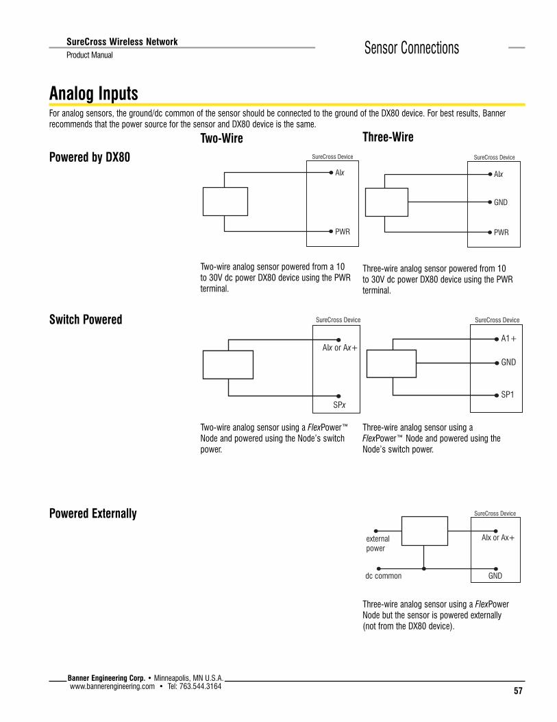
57Banner Engineering Corp. • Minneapolis, MN U.S.A.www.bannerengineering.com • Tel: 763.544.3164
SureCross Wireless Network
Product Manual Sensor Connections
AIx
PWR
SureCross Device
Analog InputsFor analog sensors, the ground/dc common of the sensor should be connected to the ground of the DX80 device. For best results, Banner recommends that the power source for the sensor and DX80 device is the same.
SureCross Device
AIx or Ax+
SPx
SureCross Device
dc common
external power
AIx or Ax+
GND
Three-wire analog sensor using a FlexPower Node but the sensor is powered externally (not from the DX80 device).
Two-wire analog sensor using a FlexPower™ Node and powered using the Node’s switch power.
Two-wire analog sensor powered from a 10 to 30V dc power DX80 device using the PWR terminal.
Powered by DX80
Switch Powered
Two-Wire Three-Wire
AIx
GND
PWR
SureCross Device
Powered Externally
GND
SureCross Device
A1+
SP1
Three-wire analog sensor powered from 10 to 30V dc power DX80 device using the PWR terminal.
Three-wire analog sensor using a FlexPower™ Node and powered using the Node’s switch power.

58
Banner Engineering Corp. • Minneapolis, MN U.S.A.www.bannerengineering.com • Tel: 763.544.3164
SureCross Wireless Network Product ManualSensor Connections
Thermocouple
Wire Colors
TC Type − Wire + WireJ red white
K red yellow
R red black
RTD
A1+
A1−
DI1
SureCross Device
This wiring diagram applies to a standard three-wire RTD sensor. When using thermocouple and RTD sensors, the quality of the power supply influences the accuracy of the signal.
Banner QT50U Long-range Ultrasonic Sensor
sensor power (bn)
dc common (bu)
(wh)
(bk)
QT50U
A1−
GND
SP1
A1+
SureCross Device
Four-wire QT50U sensor, using a FlexPower™ Node, and powered using the Node’s switch power terminal. The QT50U output is set to 4–20 mA.
Ax+
Ax−
TC
SureCross Device
+
−
Pressure Sensor
Proximity Sensor, Non-NAMUR
SP1
A1+
GND
Power
SureCross Device
SP1
A1+
SureCross Device
Three-wire non-NAMUR proximity sensor using a FlexPower™ Node and powered using the Node’s switch power.
Two-wire pressure sensor using a FlexPower™ Node and powered using the Node’s switch power.
Proximity Sensor, NAMUR
SP1
A1+
SureCross Device
Two-wire NAMUR proximity sensor using a FlexPower™ Node and powered using the Node’s switch power.

59Banner Engineering Corp. • Minneapolis, MN U.S.A.www.bannerengineering.com • Tel: 763.544.3164
SureCross Wireless Network
Product Manual Sensor Connections
AOxexternalpower
GND
SureCross Device
dc common
Analog OutputsFor analog sensors, the ground/dc common of the sensor should be connected to the ground of the DX80 device. For best results, Banner recommends that the power source for the sensor and DX80 device is the same.
Three-wire analog output device powered externally (not from the DX80 device).
AOx
PWR
GND
SureCross Device
Three-wire analog output device powered off the DX80 device.
Drive/MotorController
AOx
GND
AI+
AI−
SureCross Device
When the AI- can be referenced to ground, use this wiring diagram for drive/motor controllers.
Drive/motorcontrollers
AOx
GND
AI+
AI−
SureCross Device
When the AI- cannot be referenced to ground, use this wiring diagram for drive/motor controllers.

60
Banner Engineering Corp. • Minneapolis, MN U.S.A.www.bannerengineering.com • Tel: 763.544.3164
SureCross Wireless Network Product ManualPower Solutions
SureCross™ Power SolutionsPower solutions and battery life calculations for some sensors using FlexPower Nodes
BWA-SOLAR-001: Solar supply that includes the solar panel, rechargeable batteries, and solar power controller.
DX81: Single battery supply moduleDX81H: Single battery supply module designed specifically to power the DX99 Intrinsically Safe devices with polycarbonate housings
DX81P6: 6-pack of lithium batteries
formerly known as 140386 rev C
This document is now part of the SureCross DX80 Wireless I/O Network Manual, Banner part number 132607. These pages are extracted directly from the manual and no longer list the 6-digit part number specific to the original, standalone reference guide.

61Banner Engineering Corp. • Minneapolis, MN U.S.A.www.bannerengineering.com • Tel: 763.544.3164
SureCross Wireless Network
Product Manual Power Solutions
10–30V dcFor locations with power, the 10–30V dc devices offer an easy-to-install solution for sensing devices.
• 10–30V dc can power more sensors and more types of sensors to obtain the necessary data.
• The number of sensors powered by the SureCross device is only limited by the number of I/O points available.
• The Node may be set to high-speed I/O sample and reporting rates for quicker data collection.
FlexPower™Banner’s FlexPower technology offers a true wireless solution by allowing most FlexPower devices to operate using either 10–30V dc, 3.6V lithium D cell batteries, or solar power.
• The FlexPower Node may be powered from 10–30V dc and use an external battery supply module to provide a battery back-up solution.
• When a FlexPower Node receives 10–30V dc, it operates like a standard 10–30V dc Node.
• Good applications for FlexPower devices operating from batteries include sensors that require no or very little power, including dry contacts, RTDs, and thermocouples.
FlexPower with Switched PowerSome FlexPower devices include an internal power supply, called switched power (SP), for powering sensors that require 5, 10, or 15V power (ideally, 4–20 mA loop-powered sensors).
• To extend battery life, after the sensor takes a reading, the Node shuts down the sensor to conserve power. To reduce power consumption, slower sample and reporting rates are used. Faster sample and report rates can be configured, but this will decrease the battery’s life.
• The FlexPower switched power management system can operate a FlexPower Node and a sensing device for up to five years on a single lithium D cell.
Internal Battery FlexPower DevicesA few FlexPower devices operate using a 3.6V lithium D cell battery integrated into the housing. These integrated battery devices:
• Operate only from the battery and cannot use an external power supply• Are limited in the available I/O because of the limited connectivity• Can only be powered from the integrated battery
Solar Power AssemblyBanner’s Solar Power Assembly can be used to power up to two radio devices, including a FlexPower Node, a FlexPower Gateway, or a data radio.
When used with a FlexPower Node and sensors, the Solar Power Assembly can supply enough power to run most sensors at higher sample and report rates than a single battery can reasonably support. Rechargeable batteries power the devices while the solar panel recharges the batteries.

62
Banner Engineering Corp. • Minneapolis, MN U.S.A.www.bannerengineering.com • Tel: 763.544.3164
SureCross Wireless Network Product ManualPower Solutions
Battery Life Calculations
Analog ConfigurationThe battery life calculations for some analog sensors are shown in the table below.
Manufacturer Device Model Boost Voltage Warmup Time1 Banner U-Sonic/Distance QT50ULBQ6-75390 15V 500 ms
2 Esterlink/KPSI Submersible Level KPSI Series 700 10V 10 ms
3 Turck Pressure PT100R-11-L13-H1131 10V 10 ms
Battery Life in Years
Sample and Report Rates1 second 2 seconds 4 seconds 16 seconds 64 seconds 5 minutes 15 minutes
1 0.00 0.00 0.00 0.26 0.91 2.61 4.45
2 0.87 1.45 2.15 3.32 3.89 4.25 4.25
3 0.87 1.45 2.15 3.32 3.89 4.25 4.25
Note: Battery life calculations are based on the sensor operating 24 hours a day, 365 days a year.
For each sensor characterized, a boost voltage and warmup time was specified. The sample and reports rates were varied to calculate the estimated battery life. For example, a Banner QT50ULBQ6-75390 sensor set to a boost voltage of 15 volts, a warm-up time of 500 milliseconds, and a sample and report rate of 15 minutes, should have a battery life of 4.45 years.
QT50ULBQ6-75390
PT100R-11-L13-H1131KPSI Series 700
0.0
0.5
1.0
1.5
2.0
2.5
3.0
3.5
4.0
4.5
5.0
1 sec 2 sec 4 sec 16 sec 64 sec 5 min 15 min
Sample and Report Rates
DX81
Bat
tery
Life
(Yea
rs)

63Banner Engineering Corp. • Minneapolis, MN U.S.A.www.bannerengineering.com • Tel: 763.544.3164
SureCross Wireless Network
Product Manual Power Solutions
Discrete ConfigurationThe battery life calculations for some discrete sensors are shown in the table below.
Manufacturer Device Model Boost Voltage Warmup Time
1 Banner Optical SM312DQD-78419 5V 4 ms
2 Turck Inductive Proximity Bi10U-M30-AP6X-H1141 10V 10 ms
Battery Life in Years
Sample and Report Rates
62.5 ms 125 ms 250 ms 500 ms 1 second 2 seconds 16 seconds
1 0.97 1.67 2.62 3.74 4.75 5.49 6.28
2 0.20 0.40 0.72 1.27 2.05 2.99 5.07
Note: Battery life calculations are based on the sensor operating 24 hours a day, 365 days a year.
For each sensor characterized, a boost voltage and warmup time was specified. The sample and reports rates were varied to calculate the estimated battery life. For example, a Banner Optical sensor, model SM312DQD-78419, set to a boost voltage of 5 volts, a warm-up time of 4 milliseconds, and a sample and report rate of 16 seconds, should have a battery life of just over 6 years.
The curves for discrete devices represent a “worst case” as far as battery use because we are assuming for each sample of the sensor’s output a change in state has occurred (e.g., target present to target absent or vice versa), sending a radio message from Node to Gateway. No messaging occurs unless there is a change to report. Actual battery life depends on how many state changes actually occur.
SM312DQD-78419
Bi10U-M30-AP6X-H1141
0
1
2
3
4
5
6
7
62.5 ms 125 ms 250 ms 500 ms 1 sec 2 sec 16 sec
DX81
Bat
tery
Life
(Yea
rs)
Sample and Report Rates

64
Banner Engineering Corp. • Minneapolis, MN U.S.A.www.bannerengineering.com • Tel: 763.544.3164
SureCross Wireless Network Product ManualPower Solutions
Temperature and Humidity SensorThe following battery life calculations are based on reading/reporting one register or reading/reporting the contents of all three registers.
All battery life calculations are approximations based on a strong radio signal. Weaker radio connections and missed packets will decrease the battery life.
These values are estimated based on the current hardware and software configuration and are subject to change without notice. Environmental conditions will also contribute to the battery’s lifespan. Current estimates are based on a battery operating at room temperature.
0.00
0.50
1.00
1.50
2.00
2.50
3.00
3.50
4.00
.125 .500 1 4 8 16 64
Reading 1 register
Reading 3 registers
DX81
Bat
tery
Life
(Yea
rs)
Sample and Report Rate (sec)

65Banner Engineering Corp. • Minneapolis, MN U.S.A.www.bannerengineering.com • Tel: 763.544.3164
SureCross Wireless Network
Product Manual Power Solutions
RTD FlexPower NodeSample Rate Report Rate Battery Life (DX81) Battery Life (DX81P6)
1 500 ms 500 ms 189 days (0.52 years) 1136 days (3.1 years)
2 500 ms 1 second 293 days (0.8 years) 1761 days (4.8 years
3 1 second 2 seconds 447 days (1.22 years) 2687 days (7.36 years)
4 1 second 4 seconds 574 days (1.57 years) 3448 days (9.44 years)
5 1 second 8 seconds 614 days (1.68 years) 3689 days (10.1 years)
6 1 second 16 seconds 835 days (2.29 years) 5013 days (13.73 years)
Battery Life (DX81)
Battery Life (DX81P6)
0
2
4
6
8
10
12
14
16
1 2 3 4 5 6
Year
s
Data Points

66
Banner Engineering Corp. • Minneapolis, MN U.S.A.www.bannerengineering.com • Tel: 763.544.3164
SureCross Wireless Network Product ManualPower Solutions
DX81 Battery Supply Module
DX80 FlexPower Node with MINI-BEAM
Averaging Fluke meter
BWA-HW-010 Cable, FlexPower Current Monitoring
Calculating Battery LifeTo measure the current draw of a system similar to the one shown below, use Banner cable BWA-HW-0010.
To measure,
1. Connect the cable to the FlexPower Node and the battery supply module as shown below. The cable’s male end plugs into the FlexPower Node and the female end plugs into the battery module.
2. Connect an averaging Fluke meter to the leads. Set the meter to read in amps, not milliamps.
3. Turn off the Node’s LCD panel by clicking button 2 five times. 4. Allow the meter to measure the operation for at least 10 times the length of the
sample rate.
To estimate the battery life in hours, use the following equation:
Battery life (hours) =16,000 mA Hr
average current (mA)
To estimate the battery life in years, use the following equation:
Battery life (years ) =16,000 mA Hr
average current (mA) × 8736

67Banner Engineering Corp. • Minneapolis, MN U.S.A.www.bannerengineering.com • Tel: 763.544.3164
SureCross Wireless Network
Product Manual Power Solutions
Solar Powered SystemsFor installations without wired power, a solar powered system with an integrated solar controller and rechargeable batteries may be used to power data radios, FlexPower Gateways, or FlexPower Nodes connected to sensors that require more power than a single battery unit can supply.
Powering a data radio or data radio repeater with a solar panel allows for the expansion of the wireless network to installations with no reliable power source.
Item Model No. Description1 BWA-SOLAR-001 FlexPower Solar Supply, includes panel, solar controller, rechargeable batteries, and mounting
materials
2 DX80DR*M Data radio, 900MHz or 2.4GHz
3 DX80N9X2S2N2M2 FlexPower Node, 900MHz, Boost Power, 2 discrete IN, 2 NMOS discrete OUT, 2 analog IN (2.4GHz also available)
4 QT50U-75390 U-GAGE Long range ultra-sonic sensor, low power consumption
5 MQDC1-501.5 Cable, RS-485 quick disconnect, 5-pin Euro, straight, 0.5 m
1
1
2
3
4
5
5

68
Banner Engineering Corp. • Minneapolis, MN U.S.A.www.bannerengineering.com • Tel: 763.544.3164
SureCross Wireless Network Product ManualPower Solutions
Host System
Data RadioNID A
Data Radio RepeaterNID A
GatewayNID 1
Data RadioNID A
Node NID 1
Node NID 1
Solar power system with an integrated solar controller and rechargeable batteries
The example system shows a solar power system powering data radios and Gateways, expanding the wireless network far beyond the limits of wired power sources..
Item Model No. Description1 BWA-SOLAR-001 FlexPower Solar Supply, includes panel, batteries, and mounting materials
2 DX80DR*M Data radio, 900MHz or 2.4GHz
3 DX80N... FlexPower Nodes or Nodes
4 CSRB-M1250M125.47M125.73 Cable, RS-485, quick disconnect, 5-pin Euro, male trunk, female branches, black*
5 MQDC1-501.5 Cable, RS-485 quick disconnect, 5-pin Euro, straight, 0.5 m*
6 DX80DR... Data radio repeater
* For RS-232 communications, an RS-232 crossover cable must be used between the RS-485 and the data radio or Gateway.
1
3
4
5
1
2
2
3
6
5

69Banner Engineering Corp. • Minneapolis, MN U.S.A.www.bannerengineering.com • Tel: 763.544.3164
SureCross Wireless Network
Product Manual Power Solutions
Parallel Solar SystemsTwo or more solar systems can be directly ORed together using a splitter cable. Using the Solar Supply in parallel provides a modular approach to incrementally increase the capacity in some challenging applications or locations.
Power Splitter cable, female trunk to male branches, 5-pin Euro-style
Battery Backup FeatureThe FlexPower Solar Supply can be ORed with the DX81P6 Battery Supply Module using the CSRB-M1250M125.47M125.73 splitter cable. When the solar panel temporarily disconnects the load because of a lack of sunlight, the DX81P6 Battery Supply Module supports the system and powers the load. This battery backup can support a sensor system consisting of a 2-wire transmitter powered continuously with 15V at 20 mA and a DX80 Node transmitting once per second for up to 30 days.
Optional mapping allows a battery backup function to be mapped to a wireless error output to determine if the devices are powered by the solar panel assembly or the battery supply module.
Item Model No. Description1 BWA-SOLAR-001 FlexPower Solar Supply, includes panel, batteries, and mounting materials
2 DX80N... FlexPower Nodes or Nodes
1
2

70
Banner Engineering Corp. • Minneapolis, MN U.S.A.www.bannerengineering.com • Tel: 763.544.3164
SureCross Wireless Network Product ManualPower Solutions
Wireless Network Range ExtensionFor extending the range of the wireless network, the solar panel and rechargeable battery pack powers data radios and special FlexPower Gateways.
In the system shown, the solar panel system powers a remotely located data radio and Gateway. FlexPower Nodes make up the remainder of the wireless network. To extend this wireless network even farther from the host system, a solar panel powered data radio repeater can be used.
Data Radio
Autonomous Process Monitoring with Continuous Sensor OperationA single FlexPower Solar Supply can supply any continuously powered 4–20 mA, two-wire transmitter at 13V and power the DX80 FlexPower Node for continuous sensor operation.
This application requires at least 1.7 hours of sun per day and the battery provides about 10 days of autonomy with a full transmitter signal of 20 mA. Marginal solar situations can be supplemented with a DX81P6 Battery Supply Module acting as a battery backup unit to add an additional month of autonomous operation.
The FlexPower Node’s boost converter provides an adjustable continuous 21V courtesy power output.
4–20 mA two-wire pressure transmitter
Host System
Item Model No. Description1 BWA-SOLAR-001 FlexPower Solar Supply, includes panel, batteries, and mounting materials
2 DX80N... FlexPower Nodes
3 DX80N9X2S-CS1 FlexPower Node for continuous sensor operation
4 DX80G...
5 DX80G*M2S FlexPower Gateway
6 DX80DR*M Data Radio
7 CSRB-M1250M125.47M125.73 Power splitter cable
1
1
2
3
4
5
6
6
7

71Banner Engineering Corp. • Minneapolis, MN U.S.A.www.bannerengineering.com • Tel: 763.544.3164
SureCross Wireless Network
Product Manual Maintenance and Repairs
Maintenance and Repairs
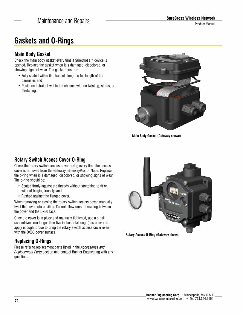
72
Banner Engineering Corp. • Minneapolis, MN U.S.A.www.bannerengineering.com • Tel: 763.544.3164
SureCross Wireless Network Product ManualMaintenance and Repairs
Main Body GasketCheck the main body gasket every time a SureCross™ device is opened. Replace the gasket when it is damaged, discolored, or showing signs of wear. The gasket must be:
• Fully seated within its channel along the full length of the perimeter, and
• Positioned straight within the channel with no twisting, stress, or stretching.
Main Body Gasket (Gateway shown)
Rotary Access O-Ring (Gateway shown)
Rotary Switch Access Cover O-RingCheck the rotary switch access cover o-ring every time the access cover is removed from the Gateway, GatewayPro, or Node. Replace the o-ring when it is damaged, discolored, or showing signs of wear. The o-ring should be:
• Seated firmly against the threads without stretching to fit or without bulging loosely, and
• Pushed against the flanged cover.When removing or closing the rotary switch access cover, manually twist the cover into position. Do not allow cross-threading between the cover and the DX80 face.
Once the cover is in place and manually tightened, use a small screwdriver (no longer than five inches total length) as a lever to apply enough torque to bring the rotary switch access cover even with the DX80 cover surface.
Replacing O-RingsPlease refer to replacement parts listed in the Accessories and Replacement Parts section and contact Banner Engineering with any questions.
Gaskets and O-Rings

73Banner Engineering Corp. • Minneapolis, MN U.S.A.www.bannerengineering.com • Tel: 763.544.3164
SureCross Wireless Network
Product Manual Maintenance and Repairs
DX81 and DX81H Battery Supply ModulesTo replace the lithum “D” cell battery in the DX81 FlexPower™ battery kit used with a FlexPower Node,
1. Unplug the battery device from the SureCross device it powers. 2. Remove the four screws mounting the battery pack face plate to the body.3. Remove the face plate. 4. Remove the discharged battery and replace with a new battery. Verify the battery’s
positive and negative terminals align to the positive and negative terminals of the battery holder mounted within the case.
5. After replacing the battery, allow up to 60 seconds for the device to power up.When removing the battery, press the battery towards the negative terminal to compress the spring. Pry up on the battery’s positive end to remove from the battery holder.
Properly dispose of your used battery by taking it to a hazardous waste collection site, an e-waste disposal center, or any other facility qualified to accept lithium batteries. Always dispose of the battery in accordance with applicable local regulations.
As with all batteries, these are a fire, explosion, and severe burn hazard. Do not burn or expose them to high temperatures. Do not recharge, crush, disassemble, or expose the contents to water.
Replacement battery model number: BWA-BATT-001. For pricing and availability, contact Banner Engineering.
DX81 Battery Replacement
Battery Replacement

74
Banner Engineering Corp. • Minneapolis, MN U.S.A.www.bannerengineering.com • Tel: 763.544.3164
SureCross Wireless Network Product ManualMaintenance and Repairs
DX80 Integrated BatteryTo replace the lithium “D” cell battery in any integrated battery model:
1. Remove the four screws mounting the battery pack face plate to the body and remove the face plate.
2. Remove the discharged battery and replace with a new battery. Only use a 3.6V lithium battery from Xeno, model number XL-205F.
3. Verify the battery’s positive and negative terminals align to the positive and negative terminals of the battery holder mounted within the case. The negative end is toward the spring. Caution: There is a risk of explosion if the replacement battery is incorrect.
4. After replacing the battery, allow up to 60 seconds for the device to power up.
When removing the battery, press the battery towards the negative terminal to compress the spring. Pry up on the battery’s positive end to remove from the battery holder. Properly dispose of your used battery according to local regulations by taking it to a hazardous waste collection site, an e-waste disposal center, or other facility qualified to accept lithium batteries.
As with all batteries, these are a fire, explosion, and severe burn hazard. Do not burn or expose them to high temperatures. Do not recharge, crush, disassemble, or expose the contents to water.
Replacement battery model number: BWA-BATT-001. For pricing and availability, contact Banner Engineering.

75Banner Engineering Corp. • Minneapolis, MN U.S.A.www.bannerengineering.com • Tel: 763.544.3164
SureCross Wireless Network
Product Manual Maintenance and Repairs
DX99...B FlexPower Nodes with Metal HousingTo replace the lithium “D” cell battery in the device,
1. Unscrew the lid on the back side of the metal enclosure.
2. Remove the discharged battery and replace with a new battery. Only use a 3.6V lithium battery from Xeno, model number XL-205F.
3. Verify the battery’s positive and negative terminals align to the positive and negative terminals of the battery holder mounted within the case. The negative end is toward the spring. Caution: There is a risk of explosion if the replacement battery is incorrect.
4. Screw on the lid and tighten.
5. After replacing the battery, allow up to 60 seconds for the device to power up.
When removing the battery, press the battery towards the negative terminal to compress the spring. Pry up on the battery’s positive end to remove from the battery holder. Properly dispose of your used battery according to local regulations by taking it to a hazardous waste collection site, an e-waste disposal center, or other facility qualified to accept lithium batteries.
As with all batteries, these are a fire, explosion, and severe burn hazard. Do not burn or expose them to high temperatures. Do not recharge, crush, disassemble, or expose the contents to water.
Replacement battery model number: BWA-BATT-001. For pricing and availability, contact Banner Engineering.
Warning: Explosions may result in death or serious injury. Do not remove the instrument cover or open the wiring housing in explosive atmospheres when power and communications are on. Remove the battery-powered device from the hazardous location before opening the cover and replacing the battery.
Warning: The replacement battery MUST be a Banner approved battery, model number BWA-BATT-001. Use of a different battery will VOID the intrinsic safety rating of this device and may result in an explosion!
Warning: When replacing the battery, the negative end of the battery holder is the side with the spring terminal. This side is marked with a minus (−) sign.
Warning: Do not attempt to recharge the battery. These batteries are not rechargeable. Recharging may cause serious injury to personnel or damage the equipment. Replace only with factory recommended batteries.

76
Banner Engineering Corp. • Minneapolis, MN U.S.A.www.bannerengineering.com • Tel: 763.544.3164
SureCross Wireless Network Product ManualMaintenance and Repairs
DX99...D FlexPower Nodes with Low-Profile Metal HousingTo replace the lithium “D” cell battery in the device,
1. Unscrew the lid on of the metal enclosure.
2. Remove the discharged battery and replace with a new battery. Only use a 3.6V lithium battery from Xeno, model number XL-205F.
3. Verify the battery’s positive and negative terminals align to the positive and negative terminals of the battery holder mounted within the case. Caution: There is a risk of explosion if the replacement battery is incorrect.
4. Screw on the lid and tighten.
5. After replacing the battery, allow up to 60 seconds for the device to power up.
When removing the battery, press the battery towards the negative terminal to compress the spring. Pry up on the battery’s positive end to remove from the battery holder. Properly dispose of your used battery according to local regulations by taking it to a hazardous waste collection site, an e-waste disposal center, or other facility qualified to accept lithium batteries.
As with all batteries, these are a fire, explosion, and severe burn hazard. Do not burn or expose them to high temperatures. Do not recharge, crush, disassemble, or expose the contents to water.
Replacement battery model number: BWA-BATT-001. For pricing and availability, contact Banner Engineering.
Warning: Explosions may result in death or serious injury. Do not remove the instrument cover or open the wiring housing in explosive atmospheres when power and communications are on. Remove the battery-powered device from the hazardous location before opening the cover and replacing the battery.
Warning: The replacement battery MUST be a Banner approved battery, model number BWA-BATT-001. Use of a different battery will VOID the intrinsic safety rating of this device and may result in an explosion!
Warning: When replacing the battery, the negative end of the battery holder is the side with the spring terminal. This side is marked with a minus (−) sign.
Warning: Do not attempt to recharge the battery. These batteries are not rechargeable. Recharging may cause serious injury to personnel or damage the equipment. Replace only with factory recommended batteries.

77Banner Engineering Corp. • Minneapolis, MN U.S.A.www.bannerengineering.com • Tel: 763.544.3164
SureCross Wireless Network
Product Manual Troubleshooting
Troubleshooting

78
Banner Engineering Corp. • Minneapolis, MN U.S.A.www.bannerengineering.com • Tel: 763.544.3164
SureCross Wireless Network Product ManualTroubleshooting
Startup ProblemsProblem SolutionRadio won’t wake up. While in hibernation mode, the radio does not operate. All SureCross devices powered from an integrated
battery ship from the factory in hibernation mode to conserve the battery. To wake the device, press and hold button 1 for five seconds. To put any FlexPower or integrated battery SureCross radio into hiberna-tion mode, press and hold button 1 for five seconds. The radio is in hibernation mode when the LEDs stop blinking, but in some models, the LCD remains on for an additional minute after the radio enters hiberna-tion mode. After a device has entered hibernation mode, you must wait one minute before waking it.
Sensors not powered. Many SureCross devices have several switch power outputs for powering sensors. Enable the power sup-plies using the I/O point parameters for sensor supply #, supply output voltage, and warm-up time.
Radio seems only partially powered
If your ribbon cable has been unplugged from the radio board, verify the ribbon cable is fully seated and that it has been plugged into all pins. It is possible to accidentally plug in the ribbon cable and miss the top row of pins (shown below).
When the ribbon cable is plugged in incorrectly, the radio may partially power up, but it will not be able to communicate to any sensors nor will it communicate with the wireless network.
Radio won’t go into binding mode
If you did not disconnect the power before changing the DIP switch positions, you must cycle power to the device. If you do not cycle power, the device does not register the DIP switch changes.
For devices with an integrated battery, cycle the power by removing the battery for one minute. Replace the battery.
Messages, Error Codes, and Other Problems

79Banner Engineering Corp. • Minneapolis, MN U.S.A.www.bannerengineering.com • Tel: 763.544.3164
SureCross Wireless Network
Product Manual Troubleshooting
LED CodesLED 1 LED 2 Solution
Gateway, DX85: Power is on
Node: Good radio communication link
Gateway, DX85: Active Modbus communication
Device error.
If the LCD also reports BAD EE, contact the factory for replacement.
Gateway, DX85: Modbus communication error
For a Gateway system, a Modbus communications error indicates a bad transmission or checksum error between the host and the Gateway device. For a GatewayPro system, a Modbus communications error indicates a communications problem internal to the GatewayPro. For a Gateway and Ethernet Bridge system, a Modbus communication error indicates a communication problem between the Gateway and the Ethernet Bridge.
Solutions:
1. The default communications settings for the RS485 port are: 1 start bit, 8 data bits, no parity, 1 stop bit, and 19.2k baud. The DX80 Gateway uses Modbus RTU protocol for all communications. Supported Modbus function codes are 3, 6, and 16.
2. Verify the DX80 model supports RS485 serial communications.3. RS485 termination or biasing is not supplied on the Gateway and should be provided externally to the DX80.
(Termination is not required by the Gateway, proper biasing of the serial lines is required.)4. Bad connection or bad cable.
Node: No radio communication
There are two settings on every Node device used to synchronize to the Gateway device:
• The Node must be bound to the Gateway.• Each Node ID within that network must be set to a unique number.
Solutions:
1. If the Gateway and Node are less than two meters apart, device communication may fail (radios may saturate). If the Gateway is less than two meters from another Gateway, send and receive transmissions between all devices the Gateways communicate with fails.
2. The Gateway and Node may be too far apart to achieve synchronization – consult the factory for options.3. Use a qualified antenna on both the Gateway and Node devices.4. After any system parameter change, cycle the power to re-synchronize all devices.5. When a Node loses synchronization, it is programmed to attempt re-synchronization for five seconds, then
sleep for fifteen seconds. Synchronizing may require up to twenty seconds.6. Re-cycle power on the Gateway and Node devices.
Not blinking yellow
GatewayPro: No Modbus communication
Solution:
1. The GatewayPro’s LED 2 should always be blinking yellow to indicate Modbus communication. If the LED 2 does not blink yellow, verify the baud rates, slave IDs, parity, and stop bits are set correctly.
2. Check the cables connecting the GatewayPro to the host device.

80
Banner Engineering Corp. • Minneapolis, MN U.S.A.www.bannerengineering.com • Tel: 763.544.3164
SureCross Wireless Network Product ManualTroubleshooting
LCD MessagesMessage DefinitionBAD EE System Error. A system error typically represents a failure of the EE PROM. Contact the factory for replacement.
EC XX The XX lists the Modbus register 8 message code listed in the Modbus Error Codes section of this table.
DX80 Display shows *ERROR
The Gateway uses fully-acknowledged polling to ensure each Node RF link is robust. If a prescribed number of sequential polling cycles are not acknowledged by a Node, the Gateway considers the radio link with that Node to be timed out. All outputs on the Node in question are set to the user-selected default value or the output holds its last state (as defined in the User Configuration Tool).
If the Node’s RF link recovers and the Gateway or GatewayPro determines enough acknowledged polling messages have accumulated, the link is reinstated.
No LCD display All DX80 devices display “POWER” on the LCD for the first five to ten seconds after applying power. A DX80 Gateway always has a green LED 1 on when power is connected. DX80 Node devices flash a red LED 2 every three seconds or a green LED 1 every second depending on the RF Link status.
Battery-powered devices turn off the LCD after fifteen minutes (factory default). Push any button to reactivate the LCD.
Battery-powered devices may be in power-down mode. To put battery powered devices into power-down mode, hold button 1 for three to five seconds. To return from power-down mode, hold button 1 for three to five seconds.
Recheck the power connections and power requirements. Line-powered devices require 10 to 30V dc. Battery-powered devices require 3.6 to 5.5V dc.
After replacing the battery, allow up to sixty seconds for the device to power up.
No LED 1 No LED 2 All DX80 devices display “POWER” on the LCD for the first five to ten seconds after applying power. A DX80 Gateway always has a green LED 1 on when power is connected. DX80 Node devices flash a red LED 2 every three seconds or a green LED 1 every second depending on the RF Link status.
If no LEDs are lighting up:
1. Put battery powered devices into power-down mode using button 1 on the front panel. To put a battery device into power-down mode, hold button 1 for three to five seconds. To return from power-down mode, hold button 1 for three to five seconds.
2. Recheck the power connections and power requirements. Line powered devices require 10 to 30V dc. Battery-powered devices require 3.6 to 5.5V dc.
3. After replacing the battery, allow up to sixty seconds for the device to power up.4. The GatewayPro cannot be attached to another Modbus master device or a Modbus slave ID 1 via RS485.
Special configuration using the Web page configuration tool allows the GatewayPro to become a slave unit when necessary.

81Banner Engineering Corp. • Minneapolis, MN U.S.A.www.bannerengineering.com • Tel: 763.544.3164
SureCross Wireless Network
Product Manual Troubleshooting
Inputs and OutputsProblem SolutionParticular inputs and/or outputs are not working
Use manual scrolling mode within *RUN to freeze the I/O status on the LCD display for the device in question. Verify that when the input device changes state or changes value, the LCD mirrors the behavior.
Also verify that the LCD on the output side mirrors the linked input’s behavior. If the input device state LCD on the origination DX80 and the LCD on the destination DX80 behave the same, there may be a wiring issue or an interfacing problem. Consult the factory.
Nodes will not sample inputs unless they are in sync with a Gateway. Verify your Node is in sync with its Gateway.
Switch Power SupplyProblem SolutionThe sensor powered from the Node’s switched supplies does not get power.
There are several switched power outputs to power sensors (battery-powered devices only). Enable the power supplies using the I/O point parameters for sensor supply #, supply output voltage, and warm-up time.
Modbus Register 8 Message CodesRegister I/O 8 is reserved for device messages or Site Survey data when in Site Survey mode (for more information about how Site Survey data is stored in registers 7 and 8, refer to the Site Survey section). Conditions are detected as they occur and are immediately reported back to the Gateway. Once the message is sent back to the Gateway, the Node does not resend the message until the condition changes or there is a higher priority message. The higher the message code, the higher the priority.
The following are Modbus message codes, shown in hex, that may appear on the SureCross devices’ I/O 8 Modbus register.
0x0000 (Hex)
DefinitionMessage Code
[15:8]Data Field
[7:0]00 80 Normal operation. Device message register contents 0x0080 indicates the particular Node is synchronized
to the Gateway. (Decimal value 128.) A value of zero (0) indicates there is no device present.
01 00-FF Unknown message. The message was received correctly (correct checksum), but it is not a recognized command. This type of message is usually caused by devices with poor radio links or collocated networks that are not uniquely separated by binding codes and Network IDs. This message does not affect the performance of the network. (Decimal values 256 through 511.)
35 01 Radio Device Time-Out. (Decimal value 13569.) One of the Nodes is not responding to the Gateway’s requests; the defined polling interval with allowable missed count was reached. See the documentation in the UCT for polling or heartbeat parameters and the timeout operation. When the least significant bit is on (1), an error condition exists.
• Run site survey to determine the quality of the RF link. If no communications exist between the Gateway and Node, verify the power at the Node and all antenna connections. The blocking of RF communications may also be a result of environmental conditions that may have changed.
• The battery of a battery powered Node may need to be replaced. Although the LCD and device may appear functional, the battery may not have enough capacity to handle the current requirements of RF communications.
36 01 Modbus time-out. A Gateway timeout (time of inactivity on the serial channel) was detected. (Decimal value 13825.) When the least significant big is on (1), an error condition exists.
FE - Modbus register 8 device messages are disabled. The Modbus register 8 clears or disables message using the Gateway’s Modbus register 15. (Decimal values 65024 through 65279.)

82
Banner Engineering Corp. • Minneapolis, MN U.S.A.www.bannerengineering.com • Tel: 763.544.3164
SureCross Wireless Network Product ManualTroubleshooting
Link between Gateway and Node 1 timed out.
Link between Gateway and Node 1 recovered.
RF Link Time-Out and Recovery - Gateway and NodeThe SureCross™ DX80 wireless devices employ a deterministic link time-out method to address RF link interruption or failure. As soon as a specific Node/Gateway RF link fails, all pertinent wired outputs are de-energized until the link is recovered (see component data sheet for more information.) Through this process, users of Banner wireless networks can be assured that disruptions in the communications link result in predictable system behavior.
The link time-out feature uses a fully-acknowledged polling method to determine the RF link status of each Node on the network. If after a specified number of sequential polling cycles the Node does not acknowledge a message, the Gateway considers the link with that Node timed out. LCD displays on both the Node and Gateway show *ERROR. Following a time-out, the Node de-energizes outputs and the Gateway sets all outputs linked to the Node in question to a de-energized state. Inputs from the Node mapped to outputs on the Gateway are suspended during a link time-out.
Once a link has failed, the Gateway must receive a specified number of good RF communications packets from the Node in question before the link is reinstated. Outputs are restored to current values when the link is recovered.

83Banner Engineering Corp. • Minneapolis, MN U.S.A.www.bannerengineering.com • Tel: 763.544.3164
SureCross Wireless Network
Product Manual Troubleshooting
Restoring Factory Default SettingsRestoring the factory default settings resets the settings for:
Parameter Default SettingIP Address 192.168.0.1
Root Login root
Root Password sxi
HTTP Port 80
Modbus Server Port 502
Telnet Port 23
EtherNet/IP Protocol Disabled
To restore these settings, leave the device powered up and running and follow these steps:
1. Open the DX80 GatewayPro or DX83 Ethernet Bridge housing to access the board
2. Install the initialization (init) jumper on the pins shown3. Wait 30 seconds4. Remove the jumper5. Cycle power to the device
Using the configuration Web page, verify the parameters have returned to the factory defaults listed in the table.
Serial Communication (RS-232 or RS-485)The GatewayPro and Ethernet Bridge devices use jumpers to select between RS-485 and RS-232 communications. Because all DX80 devices are RS-485 based (at this time), verify the jumpers are set correctly. Install the four jumpers across the two top rows of pins for RS-485 and across the bottom two rows of pins for RS-232.
Initialization pins
Communications pins

84
Banner Engineering Corp. • Minneapolis, MN U.S.A.www.bannerengineering.com • Tel: 763.544.3164
SureCross Wireless Network Product ManualAccessories
Antennas and Accessories
In the United States, the FCC limits the transmitted power levels to 30 dBm EIRP, or approximately 1 Watt. When using SureCross wireless products in other countries, do not exceed the transmitted power levels allowed by the agencies in those countries that govern wireless communication.

85Banner Engineering Corp. • Minneapolis, MN U.S.A.www.bannerengineering.com • Tel: 763.544.3164
SureCross Wireless Network
Product Manual Accessories
Antennas
Part No Model No Description1 76908 BWA-9O2-C 902-928 MHz, 2 dBi, RP-SMA Male (ships with 900 MHz DX80 devices)
17721 BWA-9O5-C 902-928 MHz, 5 dBi, Rubber swivel, RP-SMA Male
2 77816 BWA-2O2-C 2.4 GHz, 2 dBi, RP-SMA Male, Rubber swivel, 3 1/4” (ships with 2.4 GHz DX80 devices)
77817 BWA-2O5-C 2.4 GHz, 5 dBi, RP-SMA Male, Rubber swivel, 6 1/2”
77818 BWA-2O7-C 2.4 GHz, 7 dBi, RP-SMA Male, Rubber swivel, 9 1/4”
3 77481 BWA-9O6-A 902-928 MHz, 6 dBd, N Female, Fiberglass, 71.5” Outdoor
4 77819 BWA-9O5-B 902-928 MHz, 5 dBd/7.2 dBi, N Female, with Ground Plane, 32” Indoor/Outdoor
5 81080 BWA-2O8-A 2.4 GHz, 8.5 dBi, N Female, 24” Indoor/Outdoor
6 81081 BWA-2O6-A 2.4 GHz, 6 dBi, N Female, 16” Indoor/Outdoor
7 77479 BWA-9Y6-A 890-960 MHz, 6.5 dBd, N Female, 6.8” x 13” Outdoor
8 77480 BWA-9Y10-A 890-960 MHz, 10 dBd, N Female, 6.8” x 24” Outdoor
Omni-Directional Antennas
1 2
3
4
56
Directional (Yagi) Antennas
7
8

86
Banner Engineering Corp. • Minneapolis, MN U.S.A.www.bannerengineering.com • Tel: 763.544.3164
SureCross Wireless Network Product ManualAccessories
Surge Suppressors
Part No: 79296Model No: BWC-LMRSFRPBDescription: Surge Suppressor, bulkhead, RP-SMA Type
Antenna CablesPart No Model No Description
77486 BWC-1MRSMN05 LMR100 RP-SMA to N Male, 0.5M
77820 BWC-1MRSMN2 LMR100 RP-SMA to N Male, 2M
Part No Model No Description
78544 BWC-1MRSFRSB0.2 RG58, RP-SMA to RP-SMAF Bulkhead, 0.2M
78337 BWC-1MRSFRSB1 RG58, RP-SMA to RP-SMAF Bulkhead, 1M
78338 BWC-1MRSFRSB2 RG58, RP-SMA to RP-SMAF Bulkhead, 2M
77488 BWC-1MRSFRSB4 RG58, RP-SMA to RP-SMAF Bulkhead, 4M
Part No Model No Description
77489 BWC-4MNFN3 LMR400 N Male to N Female, 3M
77490 BWC-4MNFN6 LMR400 N Male to N Female, 6M
77821 BWC-4MNFN15 LMR400 N Male to N Female, 15M
77822 BWC-4MNFN30 LMR400 N Male to N Female, 30M
Part No: 12477Model No: BWC-LFNBMN-DCDescription: Surge Suppressor, bulkhead, N-Type, dc Blocking

87Banner Engineering Corp. • Minneapolis, MN U.S.A.www.bannerengineering.com • Tel: 763.544.3164
SureCross Wireless Network
Product Manual Accessories
DX85 Remote Modbus RTU I/O Devices
DX85DX85...C
These remote I/O devices have a Modbus interface and are used to expand the I/O of the Gateway device or the Modbus host.
Enclosures, Relay Boxes
DX85 Part No. DX85...C Part No. Model No Description
77675 10202 DX85M6P6 DX85 Expanded Remote I/O, 6 Discrete IN, 6 Discrete OUT
77676 10201 DX85M4P4M2M2 DX85 Expanded Remote I/O, 4 Discrete IN, 4 Discrete OUT, 2 Analog IN, 2 Analog OUT (0-20 mA)
79306 10204 DX85M4P8 DX85 Expanded Remote I/O, 4 Discrete IN, 8 Discrete OUT
79307 10203 DX85M8P4 DX85 Expanded Remote I/O, 8 Discrete IN, 4 Discrete OUT
79966 10205 DX85M0P0M4M4 DX85 Expanded Remote I/O, 4 Analog IN, 4 Analog OUT (0-20 mA)Note: Add a “C” to the end of any DX85 model to order that I/O mix with an IP20 housing. The IP20 models are Class I, Division 2 certified. All list prices and data sheets remain the same for either the IP67 or the IP20 housing.
Part No. Model No. Description
11320 BWA-EF14128 Enclosure Fiberglass Hinged 14"x12"x8"
11321 BWA-EF1086 Enclosure Fiberglass Hinged 10"x8"x6"
11322 BWA-EF866 Enclosure Fiberglass Hinged 8"x6"x6"
11326 BWA-PA1412 Panel, 14 x 12
11327 BWA-PA108 Panel, 10 x 8
11328 BWA-PA86 Panel, 8 x 6
11329 BWA-PM12 Pole Mount, 12 inch
11340 BWA-PM8 Pole Mount, 8 inch
11341 BWA-PM6 Pole Mount, 6 inch
11346 IB6RP Interface Relay Box, 18-26V dc inputs, isolated relay output

88
Banner Engineering Corp. • Minneapolis, MN U.S.A.www.bannerengineering.com • Tel: 763.544.3164
SureCross Wireless Network Product ManualAccessories
FlexPower™ SensorsPart No Model No Description
78447 SM312LPQD-78447 MINI-BEAM, Low Power, 5V, Polarized Retroreflective, 3 m
78419 SM312DQD-78419 MINI-BEAM, Low Power, 5V, Diffuse, 38 cm
Part No Model No Description
79610 M12FTH1Q Temperature and Humidity Sensor, ±2% Accuracy, 1-wire serial interface
81050 M12FTH2Q Temperature and Humidity Sensor, ±3.5% Accuracy, 1-wire serial interface
Banner Part No: 75390Model No: QT50ULBQ6-75390Description: Ultra-Sonic, QT50U, 200 mm to 8 m Range
Banner Part No: 10710 (Emitter), 10711 (Receiver)Model No: QS30WEQ (Emitter), QS30WRQ (Receiver)Description: WORLD-BEAM, QS30, Range up to 100 feet
Banner Humidity Sensor Calibration Statement. This calibration statement (also available online) lists the chain with which the calibration of Banner humidity sensors is traceable to NIST standards.
Other Sensors or Sensor ComponentsPart No Model No Description10406 BWA-THERMISTOR-001 NTC Thermistor, 2 KOhms, +/-0.2%C
81930 FTH-FIL-001 Temperature and Humidity Sensor Filter, Aluminum Grill Filter Cap (default filter cap)
81931 FTH-FIL-002 Temperature and Humidity Sensor Filter, Stainless Steel Sintered Filter, 10 micrometer porosity
14275 BWA-S612-30-100 NoShok Series 612 Submersible Level Transmitter, model 612-30-1-1-N-100, 0 to 30 psig, 100’ cable
14276 BWA-S612-15-100 NoShok Series 612 Submersible Level Transmitter, model 612-15-1-1-N-100, 0 to 15 psig, 100’ cable
12433 BWA-ACC-SEN-SDI Acclima SDI-12 Soil Moisture Transducer

89Banner Engineering Corp. • Minneapolis, MN U.S.A.www.bannerengineering.com • Tel: 763.544.3164
SureCross Wireless Network
Product Manual Accessories
Power Supplies
Part No: 76972Model No: DX81Description: Battery Supply Module with mounting hardware
Part No: 82864Model No: DX81HDescription: Battery Supply Module with mounting hardware, for DX99 polycarbonate housing devices
Part No: 77674Model No: DX81P6Description: Battery Supply Module, 6 “D” cells, with mounting hardware
Part No: 78261Model No: BWA-BATT-001Description: Lithium “D” cell, single
Part No: 78473Model No: BWA-BATT-003Description: Rechargeable battery pack, controller, wiring
Part No: 81057Model No: BWA-SOLAR-001Description: FlexPower Solar Supply, includes panel (13 11/16” x 15 3/16”), controller, rechargeable battery pack, mounting hardware

90
Banner Engineering Corp. • Minneapolis, MN U.S.A.www.bannerengineering.com • Tel: 763.544.3164
SureCross Wireless Network Product ManualAccessories
Other Power AccessoriesPart No. Model No. Item
10250 BWA-SOLAR-CHARGER Wall charger for BWA-BATT-003 battery pack.
83245 BWA-SPANEL-001 Solar Panel
65837 SPS101Q DC Power Supply, 120 mA, 12–30V dc, 5-pin Euro-style QD
65848 SPS101QP DC Power Supply, 120 mA, 12–30V dc, 5-pin Euro-style QD and pigtail
77422 PS24W DC Power Supply, 500 mA, 24V dc, Demo kit power supply
74321 EZAC-E-QE5 DC Power Supply, 700 mA, 24V dc, 5-pin Euro-style QD, Hardwired AC power connection
73466 EZAC-E-QE5-QS5 DC Power Supply, 700 mA, 24V dc, 5-pin Euro-style QD, 5-pin Mini QD AC power connection
76809 PSDINA-24-4 DC Power Supply, 4 Amps, 24V dc, Terminal block connection, Converts 85-264V ac, 50/60Hz

91Banner Engineering Corp. • Minneapolis, MN U.S.A.www.bannerengineering.com • Tel: 763.544.3164
SureCross Wireless Network
Product Manual Accessories
Metal Housing Accessories
Banner Part No: 12533Model No: BWA-HW-019Description: M36 Flange Mount(For the dual chamber metal housing only)
Banner Part No: 12534Model No: BWA-HW-020Description: U-Bolt Mounting Bracket(For the dual chamber metal housing only)
Banner Part No: 11834Model No: BWA-HW-016Description: Antenna Feedthrough, SS, 1/2” NPT
Banner Part No: 11835Model No: BWA-HW-017Description: Antenna Feedthrough, SS, 3/4” NPT
Cables and Connectors
Part No: 81325Model No: BWA-HW-006Description: Adapter cable, USB to RS485, for use with the User Configuration Tool software (UCT)
Part No: 19970Model No: BWA-UCT-900Description: Adapter cable, USB to RS485, for use with the User Configuration Tool and MultiHop Configuration Tool software (UCT) (with wall plug for powering 1 Watt radios)
Part No: 83265Model No: CSRB-M1250M125.47M125.73Description: Splitter cable, 5-pin Euro-style QD, No trunk male, two female branches, black. Most commonly used with solar and other FlexPower devices.
Part No: 75286Model No: CSB-M1240M1241Description: Splitter cable, 4-pin Euro-style QD, No trunk male, two female branches, yellow. Must be used to connect the Data Radio to the 10–30V dc DX80 Gateway only.
Part No: 14642Model No: BWA-HW-026Description: Splitter cable, wall plug for external power split to 5-pin Euro-style male and 5-pin Euro female (to power a M-H at 1 Watt while configuring it through the MHCT)

92
Banner Engineering Corp. • Minneapolis, MN U.S.A.www.bannerengineering.com • Tel: 763.544.3164
SureCross Wireless Network Product ManualAccessories
Other Splitter CablesPart No. Model No. Other Splitter Cables
13250 BWA-DRSPLITTER Splitter Cable, 4-pin male trunk to DB9 Female (RS232) and 5-pin female branches
13805 CSRB-M1253.28M1253.28M1253.28 Splitter cable, for dual power sources, 5-pin Euro female to 2 5-pin Euro males
Ethernet CablesPart No. Model No. Description
77669 BWA-E2M Ethernet cable, RSCD RJ45 440, 2M
78469 BWA-E8M Ethernet cable, RSCD RJ45 440, 8M
78467 BWA-EX2M Ethernet cable, crossover, RSCD RJ45CR 440, 2M
Euro-Style CablesPart No. Model No. Description
78382 BWA-QD5.5 Prewired 5-pin Euro connector, 1/2-14 NBSM
78383 BWA-QD8.5 Prewired, 8-pin Euro connector, 1/2-14 NBSM
78384 BWA-QD12.5 Prewired 12-pin Euro connector, 1/2-14 NBSM
58912 FIC-M12F4 Euro-Style Field-Wireable Connector 4-pin Female Straight
62837 DEUR-506.6C Cable, 5-pin Euro-style, double ended, male/female, 1.83m
72333 DEE2R-51D Cable, 5-pin Euro-style, double ended, male/female, 0.3m
72334 DEE2R-53D Cable, 5-pin Euro-style, double ended, male/female, 1m
72636 DEE2R-58D Cable, 5-pin Euro-style, double ended, male/female, 2.4m
71038 MQDC1-501.5 Cable, 5-pin Euro-style, single ended, female, 0.5m
12597 MQDMC-401 Cable, 5-pin Euro-style, single ended, male, 0.5m, longer pigtails for connecting to the DX80...C
51127 MQDC1-506 Cable, 5-pin Euro-style, single ended, female, 1.83m
47812 MQDC1-515 Cable, 5-pin Euro-style, single ended, female, 4.57m
47814 MQDC1-530 Cable, 5-pin Euro-style, single ended, female, 9.14m
51128 MQDC1-506RA Cable, 5-pin Euro-style, single ended, female, right-angle, 1.83m
47813 MQDC1-515RA Cable, 5-pin Euro-style, single ended, female, right-angle, 4.57m
47815 MQDC1-530RA Cable, 5-pin Euro-style, single ended, female, right-angle, 9.14m Right-angle cordsets are not compatible with the DX70 devices.When facing the Node or Gateway toward you, and the quick disconnect connection is facing down, the right-angle cables exit to the right.
Miscellaneous CablesPart No. Model No. Description
79985 BWA-RIBBON-001 Ribbon cable, 20-pin DBL socket
10200 BWA-HW-010 Cable, FlexPower Current Monitoring

93Banner Engineering Corp. • Minneapolis, MN U.S.A.www.bannerengineering.com • Tel: 763.544.3164
SureCross Wireless Network
Product Manual Accessories
Part No. Model No. Items76907 BWA-HW-001 Mounting Hardware Kit Screw, M5-0.8 x 25mm, SS (4)
Screw, M5-0.8 x 16mm, SS (4)
Hex nut, M5-0.8mm, SS (4)
Bolt, #8-32 x 3/4”, SS (4)
76906 BWA-HW-002 DX80 Access Hardware Kit Plastic threaded plugs, PG-7 (4)
Nylon gland fittings, PG-7 (4)
Hex nuts, PG-7 (4)
Plug, 1/2” NPT
Nylon gland fitting, 1/2” NPT
76910 BWA-HW-003 PTFE Tape
16328 BWA-HW-004 Replacement Seals O-ring, rotary access cover, PG21 (2)
O-ring, body gasket (2)
Access cover, rotary, clear plastic (2)
83244 BWA-HW-009 Solar Assembly Hardware Pack Includes brackets, bolts, set screws
79438 BWA-CG.5-10 Cable Glands, 1/2-inch NPT 10 pieces, cordgrips for cable diameters 0.17’’ to 0.45’’
79984 BWA-HP.5-10 Dummy Hole Plugs, 1/2-inch NPT 10 pieces
81233 BWA-HW-007 Housing Kit, DX80 DX80 top and bottom (10)
80850 BWA-HW-008 Housing Kit, DX81 DX81 top and bottom (10)
30470 DIN-35-105 DIN Rail section, 105 mm long, 35 mm design
77161 SMBDX80DIN Bracket assembly, DIN rail, flat mount (shown above)
10283 BWA-HW-011 Terminal Block Headers, IP20, 2 pack
10878 BWA-HW-012 DX99 Antenna Extension Pack Screw, M4-0.7 x 20, pan head, black steel
Flexible Antenna Cable, 12”, SMA male to SMA female
18277 BWA-HW-031 Vent Plug, 1/2” NPT, IP67 (shown above)
18310 BWA-HW-032 Access Hardware for the “E” Housing (One 1/2” plug, one 1/2” gland)
19576 BWA-WW-037 Clear plastic retaining ring for DX99 metal housings (10 pack)
Hardware Packs and Replacement Parts
DIN Rail Bracket for DX70 and DX80 models
Vent Plug, 1/2” NPT

94
Banner Engineering Corp. • Minneapolis, MN U.S.A.www.bannerengineering.com • Tel: 763.544.3164
SureCross Wireless Network Product ManualSpecifications
General Specifications

95Banner Engineering Corp. • Minneapolis, MN U.S.A.www.bannerengineering.com • Tel: 763.544.3164
SureCross Wireless Network
Product Manual Specifications
Range*900 MHz: Up to 4.8 kilometers (3 miles)2.4 GHz: Up to 3.2 kilometers (2 miles)
Transmit Power900 MHz: 21 dBm Conducted2.4 GHz: 18 dBm Conduced, ≤20 dBm EIRP
Spread Spectrum Technology FHSS (Frequency Hopping Spread Spectrum)
Antenna ConnectorExt. Reverse Polarity SMA, 50 Ohms
Antenna Max Tightening Torque0.45 N•m (4 in•lbf)
Link TimeoutGateway: Configurable, up to 2 minutesNode: Defined by Gateway
* With the standard 2 dB antenna. High-gain antennas are available, but the range depends on the environment and line of sight. To determine the range of your wireless network, perform a Site Survey.
Radio
Power+10 to 30V dc (For European applications: +10 to 24V dc, ± 10%)FlexPower: +10 to 30V dc or 3.6 to 5.5V dc low power option (For European applications: +10 to 24V dc, ± 10% or 3.6 to 5.5V dc low power option)Internal battery: 3.6V dc low power option from an internal battery
Power Consumption. Less than 1.4 W (60 mA) at 24V dcMounting. #10 or M5 (M5 hardware included)
M5 Fasteners Max Tightening Torque. 0.56 N•m (5 in•lbf)Case Material. PolycarbonateWeight. 0.26 kg (0.57 lb.)Indicators. Two LED, bi-colorSwitches. Two Push ButtonsDisplay. Six Character LCDExternal Cable Glands. Four PG-7 type, One 1/2 NPT typeCable Glands Max Tightening Torque. 0.56 N•m (5 in•lbf)
* For European applications, power the DX80 from a Limited Power Source as defined in EN 60950-1.
General
Interface. 2-wire RS-485Baud Rates. 9.6k, 19.2k (default), or 38.4k
Data Format. 8 data bits, no parity, 1 stop bitProtocol. Modbus RTU
Communications
DX80...C ModelsEnvironmental Rating* (device case). IEC IP20; NEMA 1Environmental Rating* (in suitable enclosure). Class I, Division 2, Group A, B, C, D T4 −40 to 80° COperating Temperature.** −40 to +85° C (Electronics); −20 to +80° C (LCD)Operating Humidity. 95% max. relative (non-condensing)Radiated Immunity. 10 V/m, 80-2700 MHz (EN61000-6-2)Shock and Vibration. IEC 68-2-6 and IEC 68-2-7
Shock: 30g, 11 millisecond half sine wave, 18 shocks Vibration: 0.5 mm p-p, 10 to 60 Hz
DX80 ModelsEnvironmental Rating.* IEC IP67; NEMA 6Operating Temperature.** −40 to +85° C (Electronics); −20 to +80° C (LCD)Operating Humidity. 95% max. relative (non-condensing)Radiated Immunity. 10 V/m, 80-2700 MHz (EN61000-6-2)Shock and Vibration. IEC 68-2-6 and IEC 68-2-7;
Shock: 30g, 11 millisecond half sine wave, 18 shocks; Vibration: 0.5 mm p-p, 10 to 60 Hz
Environmental
* Please refer to the SureCross™ DX80 Wireless I/O Network product manual, Banner p/n 132607, for installation and waterproofing instructions. ** Operating the devices at the maximum operating conditions for extended periods can shorten the life of the device.

96
Banner Engineering Corp. • Minneapolis, MN U.S.A.www.bannerengineering.com • Tel: 763.544.3164
SureCross Wireless Network Product ManualSpecifications
900 MHz Models. FCC ID TGUDX80 - This device complies with FCC Part 15, Subpart C, 15.247IC: 7044A-DX8009
2.4 GHz Models. FCC ID UE300DX80-2400 - This device complies with FCC Part 15, Subpart C, 15.247 ETSI/EN: In accordance with EN 300 328: V1.7.1 (2006-05) IC: 7044A-DX8024
DX8x..C External Wiring Terminal ModelsCSA. Class I, Division 2, Groups A, B, C, D; Certificate: 1921239
Ex/A Ex nA II T4LCIE/ATEX. Zone 2; Certificate: LCIE 09 ATEX 1035 U
II 3GEx nA IIC
Radio Certifications
Classified Areas Certifications

97Banner Engineering Corp. • Minneapolis, MN U.S.A.www.bannerengineering.com • Tel: 763.544.3164
SureCross Wireless Network
Product Manual Agency Certifications
Agency Certifications

98
Banner Engineering Corp. • Minneapolis, MN U.S.A.www.bannerengineering.com • Tel: 763.544.3164
SureCross Wireless Network Product ManualAgency Certifications
The DX80 Module complies with Part 15 of the FCC rules and regulations.
FCC ID: TGUDX80 This device complies with Part 15 of the FCC Rules. Operation is subject to the following two conditions: (1) this device may not cause harmful interference, and (2) this device must accept any interference received, including interference that may cause undesired operation.
FCC NoticesIMPORTANT: The DX80 Modules have been certified by the FCC for use with other products without any further certification (as per FCC section 2.1091). Changes or modifications not expressly approved by the manufacturer could void the user’s authority to operate the equipment.
IMPORTANT: The DX80 Modules have been certified for fixed base station and mobile applications. If modules will be used for portable applications, the device must undergo SAR testing.
IMPORTANT: If integrated into another product, the FCC ID label must be visible through a window on the final device or it must be visible when an access panel, door, or cover is easily removed. If not, a second label must be placed on the outside of the final device that contains the following text: Contains FCC ID: TGUDX80.
NoteThis equipment has been tested and found to comply with the limits for a Class B digital device, pursuant to Part 15 of the FCC Rules. These limits are designed to provide reasonable protection against harmful interference in a residential installation. This equipment generates, uses, and can radiate radio frequency energy and, if not installed and used in accordance with the instructions, may cause harmful interference to radio communications. However, there is no guarantee that interference will not occur in a particular installation. If this equipment does cause harmful interference to radio or television reception, which can be determined by turning the equipment off and on, the user is encouraged to try to correct the interference by one or more of the following measures:
• Reorient or relocate the receiving antenna,• Increase the separation between the equipment and receiving
module,• Connect the equipment into an outlet on a circuit different from
that to which the receiving module is connected, and/or• Consult the dealer or an experienced radio/TV technician for help.
Antenna Warning WARNING: This device has been tested with Reverse Polarity SMA connectors with the antennas listed in Table 1 Appendix A. When integrated into OEM products, fixed antennas
require installation preventing end-users from replacing them with non-approved antennas. Antennas not listed in the tables must be tested to comply with FCC Section 15.203 (unique antenna connectors) and Section 15.247 (emissions).
FCC-Approved AntennasWARNING: This equipment is approved only for mobile and base station transmitting devices. Antenna(s) used for this transmitter must be installed to provide a separation distance of at least 20 cm from all persons and must not be collocated or operating in conjunction with any other antenna or transmitter.
DX80 Module may be used only with Approved Antennas that have been tested with this module.
Part Number Antenna Type Maximum Gain
— Integral antenna Unity gain
BWA-9O1-x Omni, 1/4 wave dipole ≤2 dBi
BWA-9O2-C Omni, 1/2 wave dipole, Swivel ≤2 dBi
BWA-9O6-A Omni Wideband, Fiberglass Radome ≤8.2 dBi
BWA-9O5-B Omni Base Whip ≤7.2 dBi
BWA-9Y10-A Yagi ≤10 dBi
Table 1. Type certified Antenna
FCC Certification 900 MHz

99Banner Engineering Corp. • Minneapolis, MN U.S.A.www.bannerengineering.com • Tel: 763.544.3164
SureCross Wireless Network
Product Manual Agency Certifications
Part Number Antenna Type Maximum Gain Maximum Power Setting
— Integral antenna Unity gain +30 dBm
BWA-9O1-x Omni, 1/4 wave dipole ≤2 dBi +30 dBm
BWA-9O2-C Omni, 1/2 wave dipole, Swivel ≤2 dBi +30 dBm
BWA-9O6-A Omni Wideband, Fiberglass Radome ≤8.2 dBi +27.8 dBm
BWA-9O5-B Omni Base Whip ≤7.2 dBi +28.8 dBm
BWA-9Y10-A Yagi ≤10 dBi +26 dBm
Table 1. Type certified Antenna
The DX80 Module complies with Part 15 of the FCC rules and regulations.
FCC ID: UE3RM1809 This device complies with Part 15 of the FCC Rules. Operation is subject to the following two conditions: (1) this device may not cause harmful interference, and (2) this device must accept any interference received, including interference that may cause undesired operation.
FCC NoticesIMPORTANT: The radio modules have been certified by the FCC for use with other products without any further certification (as per FCC section 2.1091). Changes or modifications not expressly approved by the manufacturer could void the user’s authority to operate the equipment.
IMPORTANT: The radio modules have been certified for fixed base station and mobile applications. If modules will be used for portable applications, the device must undergo SAR testing.
IMPORTANT: If integrated into another product, the FCC ID label must be visible through a window on the final device or it must be visible when an access panel, door, or cover is easily removed. If not, a second label must be placed on the outside of the final device that contains the following text: Contains FCC ID: UE3RM1809.
NoteThis equipment has been tested and found to comply with the limits for a Class B digital device, pursuant to Part 15 of the FCC Rules. These limits are designed to provide reasonable protection against harmful interference in a residential installation. This equipment generates, uses, and can radiate radio frequency energy and, if not installed and used in accordance with the instructions, may cause
harmful interference to radio communications. However, there is no guarantee that interference will not occur in a particular installation. If this equipment does cause harmful interference to radio or television reception, which can be determined by turning the equipment off and on, the user is encouraged to try to correct the interference by one or more of the following measures:
• Reorient or relocate the receiving antenna,• Increase the separation between the equipment and receiving
module,• Connect the equipment into an outlet on a circuit different from
that to which the receiving module is connected, and/or• Consult the dealer or an experienced radio/TV technician for help.
Antenna WARNING: This device has been tested with Reverse Polarity SMA connectors with the antennas listed in Table 1 Appendix A. When integrated into OEM products, fixed antennas require installation preventing end-users from replacing them with non-approved antennas. Antennas not listed in the tables must be tested to comply with FCC Section 15.203 (unique antenna connectors) and Section 15.247 (emissions).
FCC-Approved AntennasWARNING: This equipment is approved only for mobile and base station transmitting devices. Antenna(s) used for this transmitter must be installed to provide a separation distance of at least 20 cm from all persons and must not be collocated or operating in conjunction with any other antenna or transmitter.
DX80 Module may be used only with Approved Antennas that have been tested with this module.
FCC Certification 900 MHz, 1 Watt Radio

100
Banner Engineering Corp. • Minneapolis, MN U.S.A.www.bannerengineering.com • Tel: 763.544.3164
SureCross Wireless Network Product ManualAgency Certifications
The DX80 Module complies with Part 15 of the FCC rules and regulations.
FCC ID: UE300DX80-2400 This device complies with Part 15 of the FCC Rules. Operation is subject to the following two conditions: (1) this device may not cause harmful interference, and (2) this device must accept any interference received, including interference that may cause undesired operation.
FCC NoticesIMPORTANT: The DX80 Modules have been certified by the FCC for use with other products without any further certification (as per FCC section 2.1091). Changes or modifications not expressly approved by the manufacturer could void the user’s authority to operate the equipment.
IMPORTANT: The DX80 Modules have been certified for fixed base station and mobile applications. If modules will be used for portable applications, the device must undergo SAR testing.
IMPORTANT: If integrated into another product, the FCC ID label must be visible through a window on the final device or it must be visible when an access panel, door, or cover is easily removed. If not, a second label must be placed on the outside of the final device that contains the following text: Contains FCC ID: UE300DX80-2400.
NoteThis equipment has been tested and found to comply with the limits for a Class B digital device, pursuant to Part 15 of the FCC Rules. These limits are designed to provide reasonable protection against harmful interference in a residential installation. This equipment generates, uses, and can radiate radio frequency energy and, if not installed and used in accordance with the instructions, may cause harmful interference to radio communications. However, there is no guarantee that interference will not occur in a particular installation. If this equipment does cause harmful interference to radio or television reception, which can be determined by turning the equipment off and on, the user is encouraged to try to correct the interference by one or more of the following measures:
• Reorient or relocate the receiving antenna,• Increase the separation between the equipment and receiving
module,• Connect the equipment into an outlet on a circuit different from
that to which the receiving module is connected, and/or• Consult the dealer or an experienced radio/TV technician for help.
Antenna Warning WARNING: This device has been tested with Reverse Polarity SMA connectors with the antennas listed in Table 1 Appendix A. When integrated into OEM products, fixed antennas
require installation preventing end-users from replacing them with non-approved antennas. Antennas not listed in the tables must be tested to comply with FCC Section 15.203 (unique antenna connectors) and Section 15.247 (emissions).
FCC-Approved AntennasWARNING: This equipment is approved only for mobile and base station transmitting devices. Antenna(s) used for this transmitter must be installed to provide a separation distance of at least 20 cm from all persons and must not be collocated or operating in conjunction with any other antenna or transmitter.
DX80 Module may be used only with Approved Antennas that have been tested with this module.
Part Number Antenna Type Maximum Gain
— Integral antenna Unity gain
BWA-2O2-C Omni, 1/2 wave dipole, Swivel ≤2 dBi
BWA-2O5-C Omni, Collinear, Swivel ≤5 dBi
BWA-2O7-C Omni, Coaxial Sleeve, Swivel ≤7 dBi
Table 1. Type certified Antenna
FCC Certification, 2.4 GHz

101Banner Engineering Corp. • Minneapolis, MN U.S.A.www.bannerengineering.com • Tel: 763.544.3164
SureCross Wireless Network
Product Manual Agency Certifications
Certified Countries ListCountry 900 MHz (150 mW) 900 MHz (1 Watt) 2.4 GHz (65 mW)
Australia x
Austria x
Bahamas, The x x
Bahrain (Kingdom of) x
Belgium x
Brazil x
Bulgaria x
Canada x x x
Chile x
China (People’s Republic of) x
Colombia x x
Cyprus x
Czech Republic x
Denmark x
Estonia x
Egypt x
Finland x
France x
Germany x
Greece x
Hungary x
Iceland x
India x
Ireland x
Israel x *
Italy x
Latvia x
Liechtenstein x
Lithuania x
Luxembourg x
Malta x
Mexico x x x
Netherlands x
New Zealand x
Norway x
Panama x x
Poland x
Portugal x
Romania x
Saudi Arabia (Kingdom of) x

102
Banner Engineering Corp. • Minneapolis, MN U.S.A.www.bannerengineering.com • Tel: 763.544.3164
SureCross Wireless Network Product ManualAgency Certifications
Additional MessagesBulgariaAuthorization required for outdoor and public service use.
FranceIn Guyane (French Guiana) and La Reunion (Reunion Island), outdoor use not allowed.
When ordering products for use in France, add -FR to the model number. For example, the model number for a six discrete I/O Gateway would be DX80G2M6S6P6-FR.
ItalyIf used outside of own premises, general authorization is required.
LuxembourgGeneral authorization is required for public service.
CanadaThis Class A digital apparatus meets all requirements of the Canadian Interference Causing Equipment Regulations. Operation is subject to the following two conditions: (1) this device may not cause harmful interference, and (2) this device must accept any interference received, including interference that may cause undesired operation.
Cet appareil numérique de la classe A respecte toutes les exigences du Règlement sur le matériel brouiller du Canada. Le present appareil numérique n’emet pas de bruits radioélectriques dépassant les limites applicables aux appareils numeriques de le Classe A préscrites dans le Reglement sur le brouillage radioélectrique édits par le ministere des Communications du Canada.
900 MHzThis device has been designed to operate with the antennas listed on Banner Engineering’s website and having a maximum gain of 9 dBm. Antennas not included in this list or having a gain greater that 9 dBm are strictly prohibited for use with this device. The required antenna impedance is 50 ohms.
To reduce potential radio interference to other users, the antenna type and its gain should be so chosen such that the equivalent isotropically radiated power (EIRP) is not more than that permitted for successful communication.
It is Banner Engineering’s intent to fully comply with all national and regional regulations regarding radio frequency emissions. The SureCross wireless products were certified for use in these countries using the standard antenna that ships with the product. When using other antennas, verify you are not exceeding the transmit power levels allowed by local governing agencies. Customers who want to re-export this product to a country other than that to which it was sold must ensure that the device is approved in the destination country. Consult with Banner Engineering if the destination country is not on this list.
Country 900 MHz (150 mW) 900 MHz (1 Watt) 2.4 GHz (65 mW)Singapore x
Slovakia x
Slovenia x
South Africa x
Spain x
Sweden x
Switzerland x
Taiwan x **
Thailand x
United Arab Emirates x
United Kingdom x
United States of America x x x
* External antenna models
** Only specific models. Refer to certificate for the model list.

103Banner Engineering Corp. • Minneapolis, MN U.S.A.www.bannerengineering.com • Tel: 763.544.3164
SureCross Wireless Network
Product Manual Appendices
Appendices and Additional Information

104
Banner Engineering Corp. • Minneapolis, MN U.S.A.www.bannerengineering.com • Tel: 763.544.3164
Units Conversion
Units DefinedThe units parameter defines the range and/or type of data value associated with an input or output.
Selecting Units from within any configuration tool changes the units definition of several parameters, including threshold, hysteresis, and delta. For example, if the units are 0-20 mA, the threshold, hysteresis, and delta values are entered as milliampere values. Selecting Temp C changes the threshold, hysteresis, and delta units to degrees Celsius.
Signed values range from −32768 to +32767 and allow for the measurement of negative values. Signed values are typically used for measuring temperatures. Signed values are stored as two’s complement values.
Unsigned values range from 0 to 65535 and are used to measure values that do not go below zero, such as 4 to 20 mA, distance, or a counter.
Input Units0. Raw. Displays the raw A/D conversion data with data ranges from 0 to 65535. This units type is typically used only for factory calibration.
1. 4 to 20 mA. Analog unit. Modbus register contents are scaled such that 0 represents 4 mA and 65535 represents 20 mA.
2. 0 to 20 mA. Default analog input unit. Modbus register contents are scaled such that 0 represents 0 mA and 65535 represents 20 mA.
3. Discrete (On/Off). Default discrete input unit.
4. 0 to 10V (Volts). Analog input using 0 to 10V instead of current. Modbus register contents are scaled such that 0 represents 0V and 65535 represents 10V.
6. Temp C. Celsius, high resolution. Analog input for temperature devices such as thermocouples, RTD, and thermistors. In high resolution mode, temperature = (Modbus register value) ÷ 20.
7. Temp F. Fahrenheit, high resolution. Analog input for temperature devices such as thermocouples, RTD, and thermistors. In high resolution mode, temperature = (Modbus register value) ÷ 20.
8. Temp C LowRes. Celsuis, low resolution. To measure a greater temperature range, use the low resolution unit. In low resolution mode, temperature = (Modbus register value) ÷ 2.
9. Temp F Low Res. Fahrenheit, low resolution. To measure a greater temperature range, use the low resolution unit. In low resolution mode, temperature = (Modbus register value) ÷ 2.
10. Asynchronous Counter, 32-bit. The 32-bit counter value records counts up to 4.29 billion.
11. Asynchronous Counter, 16-bit. The 16-bit counter value records counts up to 65535.
Output Units0. Raw. Displays the raw A/D conversion data with data ranges from 0 to 65535. This units type is typically used only for factory calibration.
1. 4 to 20 mA. Analog unit. Modbus register contents are scaled such that 0 represents 4 mA and 65535 represents 20 mA.
2. 0 to 20 mA. Default analog input unit. Modbus register contents are scaled such that 0 represents 0 mA and 65535 represents 20 mA.
3. Discrete (On/Off). Default discrete input unit.
4. 0 to 10V (Volts). Analog unit using 0 to 10V instead of current. Modbus register contents are scaled such that 0 represents 0V and 65535 represents 10V.
5. Signed Analog, 0 to 10V. For a signed value, such as temperature, that is to be converted to a voltage out value. Use null to set the start point and span to define the range. The null value is the starting temperature to be associated with 0V. The span is the entire temperature range that is to be associated with 0 to 10V.
6. Signed Analog, 0 to 20 mA. For a signed value, such as temperature, that is to be converted to a mA out value. Use null to set the start point and span to define the range. The null value is the starting temperature to be associated with 0 mA. The span is the entire temperature range that is to be associated with 0 to 20 mA.
7. Unsigned Analog, 0 to 20 mA. For unsigned values, such as a counter, that is to be converted to a mA out value. Use the null to set the start point and span to define the range. The null value is the distance to be associated with 0 mA. The span is the entire distance range that is to be associated with 0 to 20 mA.
8. Signed Analog, 4 to 20 mA (A). In older models, this units type is for degree Celsius conversions only. Use null to set the start point and

105Banner Engineering Corp. • Minneapolis, MN U.S.A.www.bannerengineering.com • Tel: 763.544.3164
Units Conversion
span to define the range. The null value is the starting temperature to be associated with 4 mA. The span is the entire temperature range that is to be associated with 4 to 20 mA. For newer firmware models, type codes 8 and 9 are treated the same.
9. Signed Analog, 4 to 20 mA (B). In older models, this units type is for degree Fahrenheit conversions only. Use null to set the start point and span to define the range. The null value is the starting temperature to be associated with 4 mA. The span is the entire temperature range that is to be associated with 4 to 20 mA. For newer firmware models, type codes 8 and 9 are treated the same.
10. Unsigned Analog, 0 to 10V. For an unsigned value, such as 0 to 20 mA, that is to be converted to a voltage out value. Use the null to set the start point and span to define the range. The null value is the distance to be associated with 0V. The span is the entire distance range that is to be associated with 0 to 10V.
11. Counter, 16-bit. The 16-bit counter value records counts up to 65535.
12. Unsigned Analog, 4 to 20 mA. For an unsigned value, such as 0 to 10V, that is to be converted to a mA out value. Use the null to set the start point and span to define the range. The null value is the distance to be associated with 4 mA. The span is the entire distance range that is to be associated with 4 to 20 mA.
Units Conversion in the Banner Wireless SystemThe wireless devices have many different units of measure for inputs including: 0–20 mA, 4–20 mA, 0–10V dc, temperature (°C or °F), humidity (RH), 32-bit value, or 16-bit value. Outputs can be either current (4–20 mA, 0–20 mA) or voltage (0–10V dc).The following table defines the range of values and descriptions for input units. For temperature signed values, the register resolution is based on the device configuration mode: in high resolution mode the register contains 0.1° and in low resolution mode the register contains 1°.
Input Type I/O Range Holding Register Representation
Data Conversion Description
Min. Value Max. Value Min. Value Max. ValueDiscrete 0 1 0 1 -
0–20 mA 0.0 mA 20.0 mA 0 65535 (20mA ÷ 65535) × Reg Value = mA
Linear mapping of unsigned register value to current
4–20 mA 4.0 mA 20.0 mA 0 65535 ((16mA ÷ 65535) × Reg Value) + 4 = mA
Linear mapping of unsigned register value to current
0–10V dc 0.0V dc 10.0V dc 0 65535 (10V ÷ 65535) × Reg Value = V Linear mapping of unsigned register value to voltage
Temp C/F (high resolution)
-1638.3 +1638.4 -32768 32767 (Reg Value) ÷ 20 = Temp Signed Values
Temp C/F (low resolution)
−16383° +16384 -32768 32767 (Reg Value) ÷ 2 = Temp Signed Values
Counter 0 65535 0 65535 - -
16-bit T30U 0 mm 65535 mm 0 65535 None; stored as millimeter value Unsigned
Humidity 0% RH 100% RH 0 10000 (Reg Value) ÷ 100 = Relative Humidity (RH)
Unsigned
* 0.01 ma A/D resolution, 0.02 mA accuracy + 0.01% per degrees C (about 0.08 mA over ± 40 degrees)Temperature Measurements: In high resolution mode, the temperature = (Modbus register value)÷20. For high resolution temperature input, 0 in the register is interpreted as 0° and 65535 in the register (0xFFFF) is interpreted as −1 ÷ 20 = −0.05°.In low resolution mode, the temperature is (Modbus register value)÷2. For low resolution temperature input, 0 in the register is interpreted as 0° and 65535 in the register (0xFFFF) is interpreted as −1 ÷ 2 = −0.5°.

106
Banner Engineering Corp. • Minneapolis, MN U.S.A.www.bannerengineering.com • Tel: 763.544.3164
Units Conversion
Signed/Unsigned Unit TypesUsing the signed or unsigned unit type allows the user to generically map any input to any output. The signed and unsigned unit types read the null and span parameters to create the linear translation between one scale and another. The output type is set to mA or V.
Output = (Fullscale/Span)(InputValue − Null) + Offset
Output Scale Fullscale (range) Offset0–20 mA 20 mA 0 mA
4–20 mA 16 mA 4 mA
0–10V 10V 0V
Fullscale. Defined in the table; the output range
Span. The total range of values mapped to the output
Null. The starting point for the output scale
Input Value. The value mapped to the output
Offset. Defined in the table; the starting output value.
Temperature Map ExampleMap a temperature input from a Node to a 4–20 mA output. The starting temperature is −20°F and the last temperature will be 50°F (4 mA = −20°F, 20 mA = 50°F). This defines the null as −20°F and the span as 70.
With an input temperature value of −5°F, the output value will be:
Output = (Fullscale ÷ Span)(InValue − Null) + Offset
(Fullscale ÷ Span) = 16 ÷70 = 0.22857
(Value − Null ) = −5 − (−20) = 15
Offset = 4
Output = 0.22857 × 15 + 4 = 7.42 mA
Distance Map ExampleMap a distance input from a Node to a 0–10V output. The starting distance is 200mm and the last distance will be 2000mm (4 mA = 200mm, 20 mA = 2000mm). This defines the null as 200 and the span as 1800.
With an input distance reading of 1560mm, the output value will be:
Output = (Fullscale ÷ Span)(InValue − Null) + Offset
(Fullscale ÷ Span) = 10 ÷ 1800 = 0.00555
(Value − Null ) = 1560 − 200 = 1360
Offset = 0
Output = 0.00555 × 1360 + 0 = 7.54V
Alarm ConditionsFor special alarm conditions, consult the factory. The default alarm conditions are as follows:
Unsigned Alarm: 0xFFFF
Signed Alarm: 0x7FFF

107Banner Engineering Corp. • Minneapolis, MN U.S.A.www.bannerengineering.com • Tel: 763.544.3164
SureCross Wireless Network
Product Manual Extended Address Mode
Extended Address Mode OverviewThe wireless I/O network is defined by the Network ID (NID) assigned to the Gateway and all its Nodes to ensure communication. Each device within this common network also has a unique Device Address assigned.
Extended address mode adds the ability to completely isolate networks from one another by assigning a unique code, the extended address code, to all devices in a particular network. Only devices sharing the extended address code can interact or exchange data. In addition to isolating networks, the extended addressing mode allows up to 48 Nodes to connect to a single Gateway. Without extended addressing, only 15 Nodes can connect to a single Gateway.
The extended address in the Gateway defaults to a code derived from its serial number although the code can be customized using the manual binding procedure. Binding DX80 devices locks Nodes to a specific Gateway by teaching the Nodes the Gateway’s extended address code. After the devices are bound, the Nodes only accept data from the Gateway to which they are bound.
During automatic binding, the Gateway broadcasts the extended address code to all Nodes that are in binding mode. To manually bind, enter the extended address code manually into each network device. Manually binding is particularly useful when replacing or upgrading network devices.
Important: The extended addressing code is independent from the system network ID (NID). Consequently, multiple networks can share a NID and will not exchange data; the networks are completely isolated from one another. Users of the DX80 product do not need to be aware of other
nearby networks to ensure their network does not unintentionally exchange data with other networks. Assigning different NIDs to different networks improves collocation performance in dense installations; this is true whether the network is in standard addressing mode or extended addressing mode.
To select extended address mode, turn the device off. Set DIP switch 1 to the ‘ON’ position, then turn the device on. Do not set the DIP switch while the power is on to the device.
Extended Addressing Mode and Rotary Switch Mode OptionsRotary Switch Mode Extended Address Mode
Menus There are more menu options in extended address mode.
Rotary Dials The left rotary dial sets the Network ID and the right dial sets the Device Address.
On the Gateway, both rotary dials, while in the (NID) menu, set the Network ID.
On the Node both rotary dials are used to set the Device Address.
Nodes in Network A maximum of 15 Nodes can be used in the wireless network
A maximum of 48 Nodes can be used in the wireless network.

108
Banner Engineering Corp. • Minneapolis, MN U.S.A.www.bannerengineering.com • Tel: 763.544.3164
SureCross Wireless Network Product ManualRotary Dial Address Mode
Step 1 - Set up the Network ID and Device AddressThe wireless RF network is defined by the Network ID (NID) assigned to the Gateway and its Nodes. Each device within this common network must have a unique Device Address assigned.
For factory configured kits, the Network ID and Device Addresses have been assigned. Otherwise, use the Rotary Switches (shown right) to define both the NID and Device Address for each device. Follow the steps below to set up your DX80 network.
To operate more than 15 Nodes in your wireless network, refer to the instructions on extended address mode and device binding.
Setting the Network ID1. Remove rotary switch access covers. Turn counterclockwise to remove and clockwise to tighten.2. On the Gateway, set the left rotary switch to 1. The factory default NID setting on all devices is 1. Set to another Network ID when
operating more than one network in the same area.3. On all Nodes (within the same network), set the left rotary switch to 1. Assign the same NID to all devices within a single network
(hexidecimal 0-F).
Setting the Device Address4. On the Gateway, set the right rotary switch to 0.
A device address of 0 on the Gateway displays settings for the Gateway itself. To view settings for another device on the network, adjust the right rotary switch on the Gateway to the desired device address.
5. On the first Node (device address = 1), set the right rotary switch to 1. Do not change the Device ID for preconfigured kits as this would affect the factory mapping of the I/O.
6. On the second Node (device address = 2), set the right rotary switch to 2.7. Continue setting the device address for each additional Node using a unique number (...3,4,5).
Final Steps8. Install rotary switch access covers. Please refer to the Installation section for IP67 instructions. A successful RF link is identified by a
blinking green LED 1 on each node.
Network ID (NID) Device Address
Rotary Dials
Multiple NetworksWhen more than one network is operating in the same space, assign a unique Network ID (NID) to each network.
Tip
7NID
NID
9NIDNID: 9
Device: 1
NID: 7Device: 2
NID: 8Device: 2
NID: 8Device: 1
NID: 7Device: 1NID: 9
Device: 2
8
Setting up a Network Using Rotary Switch Address ModeThis set of instructions describes how to set up a SureCross wireless network using Rotary Dial Address Mode. Banner recommends using Extended Addressing Mode, but some older products may only recognize Rotary Dial Address Mode.

109Banner Engineering Corp. • Minneapolis, MN U.S.A.www.bannerengineering.com • Tel: 763.544.3164
SureCross Wireless Network
Product Manual Rotary Dial Address Mode
Step 2 - Powering the Gateway and Channel Search ModeTo apply power to the Gateway or GatewayPro, connect the 10–30V dc cable as shown.
A Gateway runs Channel Search Mode on power up or when the Gateway’s Network ID is changed. Once Channel Search Mode begins, the Gateway determines if its assigned Network ID is available for use or is already in use by another radio network.
For example, if a Gateway powers up set to Network ID 2, Channel Search Mode begins running as shown below.
Wire No. Color Description1 Brown 10–30V dc Input2 White RS485 / D1 / B / +3 Blue dc common4 Black RS485 / D0 / A / −5 Gray Comms Gnd
1. Apply power to the Gateway and set the rotary dial to a Network ID number (shown here as Network ID 2.Channel Search Mode begins running. LED 1 is solid red and LED 2 is flashing yellow. The LCD displays START CHANNL SEARCH MODE.
The selected Network ID (NID) is tested to determine availability. The test takes one minute to complete and counts down from 60 seconds. The LCD shows SEARCH NID 2 1M 0S. If the Network ID is not already in use, the LCD displays NID OK and enters RUN mode.
2. If the Network ID is already in use by another DX80 Gateway device, an IN USE message displays. Use the left rotary dial to select another ID.
3. After selecting a new Network ID, click button two once to restart Channel Search Mode.The screen cycles between displaying the current Network ID setting and a new NID setting until either the left rotary dial is changed to another Network ID or the test is aborted. (LED 1 is solid red and LED 2 flashes red.) Once a new Network ID is selected, Channel Search Mode begins again.
4. Once in RUN mode, the LCD display shows the current I/O status of the Gateway.The Gateway and GatewayPro start in *RUN mode. The LCD shows the current Network ID (NID), identifies the device, then beings cycling through the I/O points (GatewayPro has no I/O points).
To cancel Channel Search Mode, double-click button two. The word ABORT displays on the LCD and both LEDs are solid red. The Gateway enters RUN mode, operating on the Network ID chosen.
To ignore the Channel Search Mode results and use a Network ID that Channel Search Mode determined was in use, double-click button two. The word IGNORE displays on the LCD and both LEDs are solid red. The Gateway enters RUN mode, operating on the Network ID chosen despite being in use by another device.

110
Banner Engineering Corp. • Minneapolis, MN U.S.A.www.bannerengineering.com • Tel: 763.544.3164
SureCross Wireless Network Product ManualRotary Dial Address Mode
The LCD displays the text shown. While Channel Search Mode runs, LED 1 is solid red and LED 2 flashes yellow.
The device tests Network ID 2 for availability and counts down from one minute, zero seconds.
The selected Network ID is available for use. LED 1 is solid red, LED 2 is solid yellow.
STARTCHANNLSEARCHMODE
SEARCHNID 21M 0S
Is the NID in use?
No
Yes
NID OK
RUN
CUR 2NEW 2
Select new NID
Single click
button 2
IGNORE
Double click
button 2
ABORT
Double click
button 2
Apply powerto the Gateway
To cancel Channel
Search Mode
To ignore Channel
Search Mode results
Channel Search ModeThe example shown below is testing Network ID 2.

111Banner Engineering Corp. • Minneapolis, MN U.S.A.www.bannerengineering.com • Tel: 763.544.3164
SureCross Wireless Network
Product Manual Rotary Dial Address Mode
Line Powered Node Pinout Diagram
Wire No. Color Description1 Brown 10–30V dc Input
3 Blue dc common (GND)
Step 3 - Powering the NodeTo apply power to the Node, connect the 10–30V dc cable or DX81 Battery Module as shown. As soon as power is applied to the Node, the LCD displays POWER and begins cycling through the I/O points on the Node.
Step 4 - Verify Communications, Gateway and NodeGateway or GatewayProVerify LED 1 is on and green. The image shown is a Gateway. The GatewayPro has no side glands.
Status LED 1 LED 2
Power ON Green ON —
System Error Red Flash Red Flash
Modbus Communication Active — Yellow Flash
Modbus Communication Error — Red Flash
NodeVerify LED 1 is flashing green and LED 2 is off. Until communication is established with the Gateway, the Node’s LED 2 flashes red. When communication is established, the Node’s LED 1 flashes green. Nodes will not sample inputs unless they are in sync with a Gateway.
Status LED 1 LED 2
System Error Red Flash Red Flash (1 per sec)
RF Link Ok Green Flash (1 per sec) —
RF Link Loss — Red Flash (1 per 3 sec)
If testing the Gateway or GatewayPro and Node before installation, verify the Gateway device and Node are at least two meters apart or the communications may fail.
In a Gateway and Bridge system, Active Modbus communications refers to the communication between the Gateway and the Ethernet Bridge. In a GatewayPro system, the Modbus communication LED refers to the communication internal to the GatewayPro. In a Gateway only system, the Modbus communication LED refers to the communication between the Gateway and the host system.
Step 5 - Site SurveyRunning Site Survey is optional. Site Survey analyzes the radio signal between a Gateway (or GatewayPro) and a specified Node, reporting the number of data packets missed or received. To ensure reliable communication, perform the Site Survey before permanently installing your network. Only the Gateway can perform a Site Survey analysis.
Refer to the Site Survey section for detailed instructions about how to conduct a Site Survey and how to interpret the results.

112
Banner Engineering Corp. • Minneapolis, MN U.S.A.www.bannerengineering.com • Tel: 763.544.3164
SureCross Wireless Network Product ManualIndex
IndexAAccess Cover 26Address Mode
extended 106rotary switch 107
BBattery
disposal 73replacement 73
Battery Backup 69baud rate 38Binding SureCross Devices
automatic binding 17manual mode 34
CChannel Search Mode 108Collocation 27Communication Parameters
ethernet 38Communication Protocol 33Configuration
IP address 32Web page 32
DDERR Menu 13Device Address
rotary switch mode 107DINFO Menu 13DVCFG Menu 13, 38
EEthernet Bridge 31Extended Address Mode 106
FFactory Default Settings, Restoring 82FCC Certification 97FCTRY Menu 13FlexPower
battery life estimates 62internal battery 61solar 61
GGasket
main body 72
IIndustrial Ethernet Port 7, 8Installation 24
waterproof 26Isolation 28
LLEDs 6, 7Legacy Mode 106Link Failure
Gateway 40host 40Node 41
Login and Password 32Login and Password, Root 33
MMenu 13
NNetwork ID 6
rotary switch mode 107
OO-Ring 72
Pparity 38Password 32, 33Pinouts
industrial ethernet 9Power Supply
10-30V dc 61internal battery 61solar 61
Push Button 6, 7
RRegisters
signed and unsigned types 105units conversion 104
Restoring Factory Default Settings 82RF Link Time-Out 78Rotary Switch 6, 7Rotary Switch Access Cover 26Rotary Switch Address Mode 107RUN Menu 13
SSensors
analog 57connecting 52MINI-BEAM 53pressure 58sinking inputs 54sinking outputs 56sourcing inputs 53sourcing outputs 55ultrasonic 58
SITE Menu 13Site Survey
from menu 21from register commands 22interpreting results 23
slave ID 38Solar Powered Systems 67Switched Power 61
TTime-Out 40
UUnits Conversion 104
WWaterproofing 26Wiring Chamber 8
XXADR 36

113Banner Engineering Corp. • Minneapolis, MN U.S.A.www.bannerengineering.com • Tel: 763.544.3164
SureCross Wireless Network
Product Manual Index

Banner Engineering Corp., 9714 Tenth Ave. No., Minneapolis, MN USA 55441 • Phone: 763.544.3164 • www.bannerengineering.com • Email: [email protected]
P/N 132607 rev. H
For more information: Contact your local Banner representative or Banner
Corporate Offices around the world.
Corporate Headquarters Europe Latin AmericaBanner Engineering Corp.9714 Tenth Ave. NorthMpls., MN 55441 Tel: 763-544-3164www.bannerengineering.com [email protected]
Banner Engineering EuropePark Lane Culliganlaan 2F Diegem B-1831 BELGIUMTel: 32-2 456 07 80 Fax: 32-2 456 07 89 [email protected]
Contact Banner Engineering Corp. (US) or e-mailMexico: [email protected]: [email protected]
Asia - China Asia - Japan Asia IndiaBanner Engineering ChinaShanghai Rep Office Rm. G/H/I, 28th Flr. Cross Region Plaza No. 899, Lingling Road Shanghai 200030 CHINATel: 86-21-54894500 Fax: 86-21-54894511 [email protected]
Banner Engineering Japan Cent-Urban Building 305 3-23-15 Nishi-Nakajima Yodogawa-Ku, Osaka 532-0011 JAPANTel: 81-6-6309-0411 Fax: 81-6-6309-0416 www.bannerengineering.co.jp [email protected]
Banner Engineering Asia - Taiwan Neihu Technology Park 8F-2, No. 308, Sec. 1, Neihu Rd. Taipei 114 TAIWANTel: 886-2-8751-9966 Fax: 886-2-8751-2966 www.bannerengineering.com.tw [email protected]
Banner Engineering IndiaPune Head Quarters Office No. 1001 Sai Capital, Opp. ICC Senapati Bapat Road Pune 411016 INDIATel: 91-20-66405624 Fax: 91-20-66405623 www.bannerengineering.co.in [email protected]