Embed Size (px)
Citation preview

Surface Safety Products

[email protected] nov.com/pps
Table of Contents
General Information . . . . . . . . . . . . . . . . . . . . . . . . . . . . . . . . . . . . . . . . . . . . . . . . . . . . . . . . . . . . . . . . . . . . . . . . . . . . . . . . . . . . . . . .1-1Introduction . . . . . . . . . . . . . . . . . . . . . . . . . . . . . . . . . . . . . . . . . . . . . . . . . . . . . . . . . . . . . . . . . . . . . . . . . . . . . . . . . . . . . . . . . . . . . . . . . . . . . . . . . . . . . . . . . . . . . 1-1Standard Wellhead Actuators . . . . . . . . . . . . . . . . . . . . . . . . . . . . . . . . . . . . . . . . . . . . . . . . . . . . . . . . . . . . . . . . . . . . . . . . . . . . . . . . . . . . . . . . . . . . . . . . . . . . .1-2Pipeline Actuators . . . . . . . . . . . . . . . . . . . . . . . . . . . . . . . . . . . . . . . . . . . . . . . . . . . . . . . . . . . . . . . . . . . . . . . . . . . . . . . . . . . . . . . . . . . . . . . . . . . . . . . . . . . . . . .1 .3Special Application Actuators . . . . . . . . . . . . . . . . . . . . . . . . . . . . . . . . . . . . . . . . . . . . . . . . . . . . . . . . . . . . . . . . . . . . . . . . . . . . . . . . . . . . . . . . . . . . . . . . . . . .1-3Actuator Description and Principle of Operation . . . . . . . . . . . . . . . . . . . . . . . . . . . . . . . . . . . . . . . . . . . . . . . . . . . . . . . . . . . . . . . . . . . . . . . . . . . . . . . . . . .1-4Gate Valve and Actuator with Trim Codes . . . . . . . . . . . . . . . . . . . . . . . . . . . . . . . . . . . . . . . . . . . . . . . . . . . . . . . . . . . . . . . . . . . . . . . . . . . . . . . . . . . . . . . . . .1-5Standard Actuators . . . . . . . . . . . . . . . . . . . . . . . . . . . . . . . . . . . . . . . . . . . . . . . . . . . . . . . . . . . . . . . . . . . . . . . . . . . . . . . . . . . . . . . . .2-1AUD Fail-Safe Pneumatic Diaphragm Actuator . . . . . . . . . . . . . . . . . . . . . . . . . . . . . . . . . . . . . . . . . . . . . . . . . . . . . . . . . . . . . . . . . . . . . . . . . . . . . . . . . . . . .2-1Pneumatic AUP Piston Actuator . . . . . . . . . . . . . . . . . . . . . . . . . . . . . . . . . . . . . . . . . . . . . . . . . . . . . . . . . . . . . . . . . . . . . . . . . . . . . . . . . . . . . . . . . . . . . . . . . . .2-5AUH Hydraulic Actuator . . . . . . . . . . . . . . . . . . . . . . . . . . . . . . . . . . . . . . . . . . . . . . . . . . . . . . . . . . . . . . . . . . . . . . . . . . . . . . . . . . . . . . . . . . . . . . . . . . . . . . . . . .2-8AWC Wireline-Cutting Hydraulic Actuator . . . . . . . . . . . . . . . . . . . . . . . . . . . . . . . . . . . . . . . . . . . . . . . . . . . . . . . . . . . . . . . . . . . . . . . . . . . . . . . . . . . . . . . . .2-11AWC Actuator Pressure Sizing Data . . . . . . . . . . . . . . . . . . . . . . . . . . . . . . . . . . . . . . . . . . . . . . . . . . . . . . . . . . . . . . . . . . . . . . . . . . . . . . . . . . . . . . . . . . . . . . .2-14Pipeline Actuators . . . . . . . . . . . . . . . . . . . . . . . . . . . . . . . . . . . . . . . . . . . . . . . . . . . . . . . . . . . . . . . . . . . . . . . . . . . . . . . . . . . . . . . . . .3-1PA Pneumatic Surface Safety Shutdown Gate Valve . . . . . . . . . . . . . . . . . . . . . . . . . . . . . . . . . . . . . . . . . . . . . . . . . . . . . . . . . . . . . . . . . . . . . . . . . . . . . . . .3-1Actuators for Large Bore API 6D Safety Gate Valves . . . . . . . . . . . . . . . . . . . . . . . . . . . . . . . . . . . . . . . . . . . . . . . . . . . . . . . . . . . . . . . . . . . . . . . . . . . . . . . . .3-3Special Application Actuators . . . . . . . . . . . . . . . . . . . . . . . . . . . . . . . . . . . . . . . . . . . . . . . . . . . . . . . . . . . . . . . . . . . . . . . . . . . . . . . .4-1LEO™ Linear Electric Operator Actuator . . . . . . . . . . . . . . . . . . . . . . . . . . . . . . . . . . . . . . . . . . . . . . . . . . . . . . . . . . . . . . . . . . . . . . . . . . . . . . . . . . . . . . . . . . .4-1DF Dual Force Actuator . . . . . . . . . . . . . . . . . . . . . . . . . . . . . . . . . . . . . . . . . . . . . . . . . . . . . . . . . . . . . . . . . . . . . . . . . . . . . . . . . . . . . . . . . . . . . . . . . . . . . . . . . . 4-4Pneumatic Piston Actuator Pressure/Sizing Data . . . . . . . . . . . . . . . . . . . . . . . . . . . . . . . . . . . . . . . . . . . . . . . . . . . . . . . . . . . . . . . . . . . . . . . . . . . . . . . . . .4-7Safety Shutdown Valves and Systems . . . . . . . . . . . . . . . . . . . . . . . . . . . . . . . . . . . . . . . . . . . . . . . . . . . . . . . . . . . . . . . . . . . . . . . . . . . . . . . . . . . . . . . . . . . . 4-8Diaphragm/Actuator Pressure/Sizing Data . . . . . . . . . . . . . . . . . . . . . . . . . . . . . . . . . . . . . . . . . . . . . . . . . . . . . . . . . . . . . . . . . . . . . . . . . . . . . . . . . . . . . . .4-10Self-Contained Systems . . . . . . . . . . . . . . . . . . . . . . . . . . . . . . . . . . . . . . . . . . . . . . . . . . . . . . . . . . . . . . . . . . . . . . . . . . . . . . . . . . . . .5-1Self-Contained Surface Safety Shutdown Control System . . . . . . . . . . . . . . . . . . . . . . . . . . . . . . . . . . . . . . . . . . . . . . . . . . . . . . . . . . . . . . . . . . . . . . . . . .5-1Actuator Accessories . . . . . . . . . . . . . . . . . . . . . . . . . . . . . . . . . . . . . . . . . . . . . . . . . . . . . . . . . . . . . . . . . . . . . . . . . . . . . . . . . . . . . . . .6-1Introduction . . . . . . . . . . . . . . . . . . . . . . . . . . . . . . . . . . . . . . . . . . . . . . . . . . . . . . . . . . . . . . . . . . . . . . . . . . . . . . . . . . . . . . . . . . . . . . . . . . . . . . . . . . . . . . . . . . . . .6-1Mechanical Reopening Assembly . . . . . . . . . . . . . . . . . . . . . . . . . . . . . . . . . . . . . . . . . . . . . . . . . . . . . . . . . . . . . . . . . . . . . . . . . . . . . . . . . . . . . . . . . . . . . . . . .6-2Lockout Caps . . . . . . . . . . . . . . . . . . . . . . . . . . . . . . . . . . . . . . . . . . . . . . . . . . . . . . . . . . . . . . . . . . . . . . . . . . . . . . . . . . . . . . . . . . . . . . . . . . . . . . . . . . . . . . . . . . . .6-3Electric Valve Position Indicators . . . . . . . . . . . . . . . . . . . . . . . . . . . . . . . . . . . . . . . . . . . . . . . . . . . . . . . . . . . . . . . . . . . . . . . . . . . . . . . . . . . . . . . . . . . . . . . . 6-4Stem Protector . . . . . . . . . . . . . . . . . . . . . . . . . . . . . . . . . . . . . . . . . . . . . . . . . . . . . . . . . . . . . . . . . . . . . . . . . . . . . . . . . . . . . . . . . . . . . . . . . . . . . . . . . . . . . . . . . .6-5Proximity Switch . . . . . . . . . . . . . . . . . . . . . . . . . . . . . . . . . . . . . . . . . . . . . . . . . . . . . . . . . . . . . . . . . . . . . . . . . . . . . . . . . . . . . . . . . . . . . . . . . . . . . . . . . . . . . . . . 6-6Hydraulic Operator . . . . . . . . . . . . . . . . . . . . . . . . . . . . . . . . . . . . . . . . . . . . . . . . . . . . . . . . . . . . . . . . . . . . . . . . . . . . . . . . . . . . . . . . . . . . . . . . . . . . . . . . . . . . . . .6-7Fusible Operators . . . . . . . . . . . . . . . . . . . . . . . . . . . . . . . . . . . . . . . . . . . . . . . . . . . . . . . . . . . . . . . . . . . . . . . . . . . . . . . . . . . . . . . . . . . . . . . . . . . . . . . . . . . . . . . 6-8Fusible Lock-Open Caps . . . . . . . . . . . . . . . . . . . . . . . . . . . . . . . . . . . . . . . . . . . . . . . . . . . . . . . . . . . . . . . . . . . . . . . . . . . . . . . . . . . . . . . . . . . . . . . . . . . . . . . . . .6-9Hydro-Pneumatic Dampener . . . . . . . . . . . . . . . . . . . . . . . . . . . . . . . . . . . . . . . . . . . . . . . . . . . . . . . . . . . . . . . . . . . . . . . . . . . . . . . . . . . . . . . . . . . . . . . . . . . .6-10Limit Switch . . . . . . . . . . . . . . . . . . . . . . . . . . . . . . . . . . . . . . . . . . . . . . . . . . . . . . . . . . . . . . . . . . . . . . . . . . . . . . . . . . . . . . . . . . . . . . . . . . . . . . . . . . . . . . . . . . . .6-11Safety Systems . . . . . . . . . . . . . . . . . . . . . . . . . . . . . . . . . . . . . . . . . . . . . . . . . . . . . . . . . . . . . . . . . . . . . . . . . . . . . . . . . . . . . . . . . . . .7-1Operation of Basic Safety System . . . . . . . . . . . . . . . . . . . . . . . . . . . . . . . . . . . . . . . . . . . . . . . . . . . . . . . . . . . . . . . . . . . . . . . . . . . . . . . . . . . . . . . . . . . . . . . . . 7-1Elementary Control System . . . . . . . . . . . . . . . . . . . . . . . . . . . . . . . . . . . . . . . . . . . . . . . . . . . . . . . . . . . . . . . . . . . . . . . . . . . . . . . . . . . . . . . . . . . . . . . . . . . . . . 7-2Safety Monitoring and Control Systems . . . . . . . . . . . . . . . . . . . . . . . . . . . . . . . . . . . . . . . . . . . . . . . . . . . . . . . . . . . . . . . . . . . . . . . . . . . . . . . . . . . . . . . . . . .7-3Single-Well Control Systems . . . . . . . . . . . . . . . . . . . . . . . . . . . . . . . . . . . . . . . . . . . . . . . . . . . . . . . . . . . . . . . . . . . . . . . . . . . . . . . . . . . . . . . . . . . . . . . . . . . . . .7-5Multi-Well Control Systems . . . . . . . . . . . . . . . . . . . . . . . . . . . . . . . . . . . . . . . . . . . . . . . . . . . . . . . . . . . . . . . . . . . . . . . . . . . . . . . . . . . . . . . . . . . . . . . . . . . . . . .7-6System Components . . . . . . . . . . . . . . . . . . . . . . . . . . . . . . . . . . . . . . . . . . . . . . . . . . . . . . . . . . . . . . . . . . . . . . . . . . . . . . . . . . . . . . . .8-1PRV Relay . . . . . . . . . . . . . . . . . . . . . . . . . . . . . . . . . . . . . . . . . . . . . . . . . . . . . . . . . . . . . . . . . . . . . . . . . . . . . . . . . . . . . . . . . . . . . . . . . . . . . . . . . . . . . . . . . . . . . . . .8-1ESP Pressure Sensors . . . . . . . . . . . . . . . . . . . . . . . . . . . . . . . . . . . . . . . . . . . . . . . . . . . . . . . . . . . . . . . . . . . . . . . . . . . . . . . . . . . . . . . . . . . . . . . . . . . . . . . . . . . .8-2ESPHL High-Low Pressure Controller . . . . . . . . . . . . . . . . . . . . . . . . . . . . . . . . . . . . . . . . . . . . . . . . . . . . . . . . . . . . . . . . . . . . . . . . . . . . . . . . . . . . . . . . . . . . . .8-3Type ECS Pressure Sensor . . . . . . . . . . . . . . . . . . . . . . . . . . . . . . . . . . . . . . . . . . . . . . . . . . . . . . . . . . . . . . . . . . . . . . . . . . . . . . . . . . . . . . . . . . . . . . . . . . . . . . . 8-4Erosion Monitor Pilots and Flowline Accessories . . . . . . . . . . . . . . . . . . . . . . . . . . . . . . . . . . . . . . . . . . . . . . . . . . . . . . . . . . . . . . . . . . . . . . . . . . . . . . . . . . .8-5Remote Emergency Shutdown (ESD) Station . . . . . . . . . . . . . . . . . . . . . . . . . . . . . . . . . . . . . . . . . . . . . . . . . . . . . . . . . . . . . . . . . . . . . . . . . . . . . . . . . . . . . 8-6Quick Exhaust Valves . . . . . . . . . . . . . . . . . . . . . . . . . . . . . . . . . . . . . . . . . . . . . . . . . . . . . . . . . . . . . . . . . . . . . . . . . . . . . . . . . . . . . . . . . . . . . . . . . . . . . . . . . . . .8-10Pneumatic Quick Exhaust Valves . . . . . . . . . . . . . . . . . . . . . . . . . . . . . . . . . . . . . . . . . . . . . . . . . . . . . . . . . . . . . . . . . . . . . . . . . . . . . . . . . . . . . . . . . . . . . . . . .8-11Hydraulic Control Valve . . . . . . . . . . . . . . . . . . . . . . . . . . . . . . . . . . . . . . . . . . . . . . . . . . . . . . . . . . . . . . . . . . . . . . . . . . . . . . . . . . . . . . . . . . . . . . . . . . . . . . . . . 8-12Miscellaneous Wellhead and Surface Equipment . . . . . . . . . . . . . . . . . . . . . . . . . . . . . . . . . . . . . . . . . . . . . . . . . . . . . . . . . . . . . . . .9-1Quick Union Tree Caps . . . . . . . . . . . . . . . . . . . . . . . . . . . . . . . . . . . . . . . . . . . . . . . . . . . . . . . . . . . . . . . . . . . . . . . . . . . . . . . . . . . . . . . . . . . . . . . . . . . . . . . . . . .9-2
Company Profile
NOV Completion & Production Solutions
National Oilwell Varco (NOV) is a worldwide leader in the design, manufacture and sale of equipment and components used in oil and gas drilling and production operations. We are also the providers of oilfield services to the upstream oil and gas industry.
Headquartered in Houston, Texas, with more than 60,000 employees operating as a global family in 67 countries, we work with our customers in every part of the world to meet their needs by delivering exceptional products and services .
Through our broad capabilities and vision, our family of companies is positioned and ready to serve the needs of this challenging, evolving industry . We have the technical expertise, advanced equipment and readily available support necessary for our customers’ success .
NOV Completion & Production Solutions integrates technologies for well completions and oil and gas production . We design, manufacture and sell equipment and technologies needed for hydraulic fracture stimulation, well intervention and artificial lift systems. In addition, we focus on offshore production with floating production systems and subsea production technologies.
In every type of environment, we bring together engineering operational expertise and field-proven solutions with a foundation of safety and risk management that helps you control costs and achieve lasting success .
Pressure Performance Systems (PPS)We are a group within the Intervention and Stimulation Equipment (ISE) business unit, servicing the global upstream oil and gas industry . Pressure Performance Systems (PPS) formerly known as Mission Well Service Products (MWSP), has been meeting our customers’ needs since 1955 when our first centrifugal pump was manufactured. Since then we have grown our product offering and sales channels with a diverse workforce of over 800 employees in 15 countries around the world .
From concept to completion, we deliver best-in-class solutions through alignment with our customers . We aim for exceptional customer service by anticipating needs, while continuing to create shareholder value .
We serve the following market segments: • Pressure Pumping• Workover• Well Testing & Flowback• Well Intervention• Exploration and Production (E&P)

a
b
c
d
ef
g
h
i
j
k
l
m
m
Typical wellsite automated safety system components:
a . casing pressure transmitterb . wellhead pressure transmitterc . production choke/actuator assemblyd . flowline temperature transmittere . flowline pressure transmitterf . electrical linesg . hydraulic lines
h . radio systemi . solar power systemj . hydraulic/pneumatic/battery sectionk . electronics sectionl . accumulatorm . surface safety valve
Surface Safety Products (SSP)
IntroductionNOV has one of the largest offerings of remote controlled monitoring and actuator systems in the industry . We design and manufacture a complete line of pneumatic, hydraulic, electric and direct controlled actuators for christmas tree gate valves and pipeline protection appli-cations . NOV actuators can be found on many of the world’s christmas trees via major wellhead companies or via direct purchases from national and international companies . Obstacles such as low supply pressure, compact space limitations, special metallurgy or wire-cut-ting capabilities can be satisfied by our technology team.
In addition to our large line of actuators, we offer a complete line of pressure monitoring and control valves . Controls range from the industry standard NOV “stick pilots” to a series of heat and erosion detection pilots easily incorporated into any system .
To complete our safety system offerings, we provide a line of surface control panels . These range from a simple, self-contained single well system to multi-well and multi-telemetry units . Our units can be found in remote desert applications utilizing solar power generation to extreme arctic conditions utilizing electric actuators and control systems .
Many actuators are custom designed to meet unique customer requirements or applications .
[email protected] nov.com/pps
Standard Wellhead ActuatorsStandard wellhead actuators include pneumatic and hydraulic type .
AUD Diaphragm Actuator AUP Piston Actuator
Hydraulic-TypeThe NOV hydraulic actuators which include the AUH and AWC wireline-cutting actuators, are designed for easy use and feature fewer parts than other actuators—improving field performance .
Hydraulic-Type Actuator AWC Wireline-Cutting Hydraulic Actuator
Pneumatic-TypePneumatic-type actuators include the AUP and AUD actuators . The AUD actuator features a stamped cylinder design utilizing a nylon reinforIced diaphragm for pneumatically operated safety systems . AUP actuators are piston actuators which offer a wide range of sizes for pneumatically operated safety systems .
Surface Safety Products (SSP)
1 - 21 - 1

[email protected] nov.com/pps
Pipeline Actuators
AUP Pneumatic Surface Safety Shutdown Gate Valve Large Bore 6D Actuator
Special Application Actuators
LEO™ Linear Electric Operator Actuator DF Pneumatic Dual Piston Actuator
Electric-Type Pneumatic-Type
DG-3 Surface Safety Shutdown Valve
Surface Safety Products (SSP) Surface Safety Products (SSP)
Actuator Description and Principle of OperationThe surface safety valve is a full-opening, pressure-actuated, normal-ly closed gate valve . When control pressure is released, the valve is designed to close even when subjected to high flow line pressure. It closes completely and rapidly as the control pressure is released . Flowline fluid does not enter the operator mechanism, nor exhaust to the atmosphere when the valve operates .
The surface safety valve assembly consists of a hydraulic or pneu-matic actuator which operates a reverse-acting gate valve . The actuator design makes it an integral part of the valve assembly by adapting directly to the valve bonnet . Pressure applied above the piston pushes the piston, stem and gate down . This downward movement opens the gate in reverse-acting gate valves .
Pressure in the valve body is sealed at the lower stem and prevented from entering the actuator assembly . The area below the piston is vented to the atmosphere .
When control pressure above the piston is exhausted by the operation of the pilot system, the valve closes . Valve body pressure works across the area of the lower stem to force it out of the valve body, drawing the gate into the closed position . With no pressure (less than 100 psi) in the valve body, the spring returns the valve to the closed position .
A visual indication the valve is in the open position is when the stem is protruding approximately 1/4 in . above the cylinder . If the stem is protruding visually 1/4 in . more than the stroke of the valve, this is an indication the valve is closed .
Valve Shown Open Valve Shown Closed
1 - 41 - 3
[email protected] nov.com/pps
Surface Safety Products (SSP) Surface Safety Products (SSP)
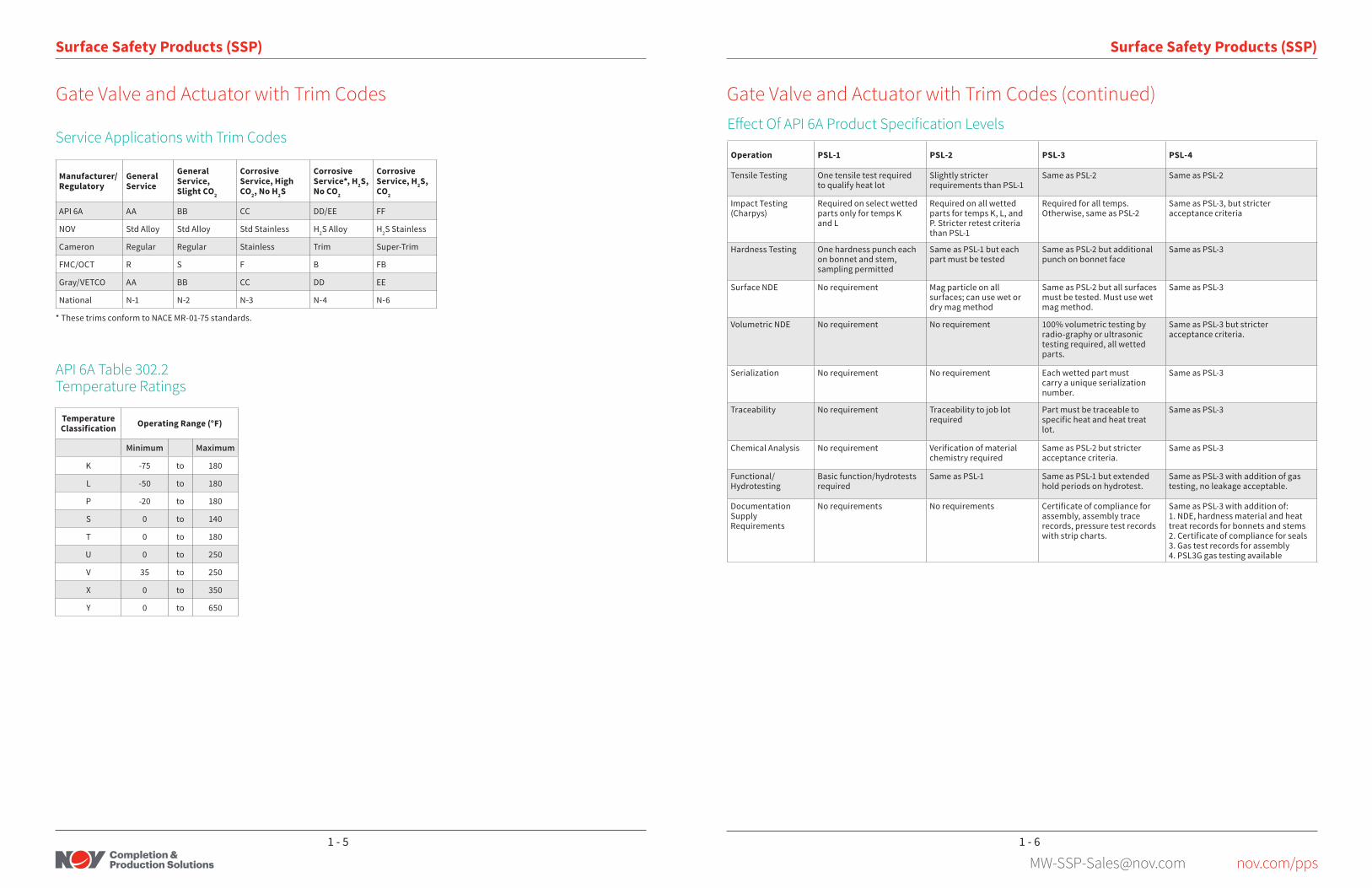
Gate Valve and Actuator with Trim Codes (continued)
Operation PSL-1 PSL-2 PSL-3 PSL-4
Tensile Testing One tensile test required to qualify heat lot
Slightly stricter requirements than PSL-1
Same as PSL-2 Same as PSL-2
Impact Testing (Charpys)
Required on select wetted parts only for temps K and L
Required on all wetted parts for temps K, L, and P. Stricter retest criteria than PSL-1
Required for all temps. Otherwise, same as PSL-2
Same as PSL-3, but stricter acceptance criteria
Hardness Testing One hardness punch each on bonnet and stem, sampling permitted
Same as PSL-1 but each part must be tested
Same as PSL-2 but additional punch on bonnet face
Same as PSL-3
Surface NDE No requirement Mag particle on all surfaces; can use wet or dry mag method
Same as PSL-2 but all surfaces must be tested. Must use wet mag method.
Same as PSL-3
Volumetric NDE No requirement No requirement 100% volumetric testing by radio-graphy or ultrasonic testing required, all wetted parts.
Same as PSL-3 but stricter acceptance criteria.
Serialization No requirement No requirement Each wetted part must carry a unique serialization number.
Same as PSL-3
Traceability No requirement Traceability to job lot required
Part must be traceable to specific heat and heat treat lot.
Same as PSL-3
Chemical Analysis No requirement Verification of material chemistry required
Same as PSL-2 but stricter acceptance criteria.
Same as PSL-3
Functional/Hydrotesting
Basic function/hydrotests required
Same as PSL-1 Same as PSL-1 but extended hold periods on hydrotest.
Same as PSL-3 with addition of gas testing, no leakage acceptable.
Documentation Supply Requirements
No requirements No requirements Certificate of compliance for assembly, assembly trace records, pressure test records with strip charts.
Same as PSL-3 with addition of:1. NDE, hardness material and heat treat records for bonnets and stems2. Certificate of compliance for seals3. Gas test records for assembly4. PSL3G gas testing available
Effect Of API 6A Product Specification Levels
Manufacturer/Regulatory
General Service
General Service, Slight CO2
Corrosive Service, High CO2, No H2S
Corrosive Service*, H2S, No CO2
Corrosive Service, H2S, CO2
API 6A AA BB CC DD/EE FF
NOV Std Alloy Std Alloy Std Stainless H2S Alloy H2S Stainless
Cameron Regular Regular Stainless Trim Super-Trim
FMC/OCT R S F B FB
Gray/VETCO AA BB CC DD EE
National N-1 N-2 N-3 N-4 N-6
* These trims conform to NACE MR-01-75 standards.
Service Applications with Trim Codes
Gate Valve and Actuator with Trim Codes
API 6A Table 302 .2Temperature Ratings
Temperature Classification Operating Range (°F)
Minimum Maximum
K -75 to 180
L -50 to 180
P -20 to 180
S 0 to 140
T 0 to 180
U 0 to 250
V 35 to 250
X 0 to 350
Y 0 to 650
1 - 61 - 5

[email protected] nov.com/pps
AUD Pneumatic DiagramActuator Mounted on Reverse-Acting Gate Valve
The NOV AUD pneumatic actuator is designed for simplicity, ease of maintenance and adaptability . Its modular design and few compo-nents help improve field performance. This actuator is designed to close upon loss of control pressure (fail-safe) . The actuator’s nylon-re-inforced diaphragm has a large piston area allowing for a low control pressure (see charts) . The maximum control pressure is 150 psi . Due to its fail-safe design, the actuator is ideally suited for wellhead, flowline, header, pipeline system and casing relief blowdown valve ap-plications . Actuators are available for API gate valve sizes from 1-13/16 in . through 12 in . and larger upon request .
Limit switches, valve position indicators, fusible and standard lockout caps, stem protectors, mechanical and hydraulic opening assemblies are also available .
Benefits• Less maintenance – Rolling diaphragm design eliminates moving o-ring seals
and leads to longer seal life .• Proven reliability – API 6A, PR2 Appendix F qualified packing.• Lightweight – Easy to install and maintain . Can be redressed without special
tools or external pressure sources .• Quick disconnect – Actuator can be removed from the valve without the use
of special tools or an external pressure source .• Large diaphragm area – Permits use of a low pressure air or gas control
system . A relief valve on the cylinder acts to protect against damage to the diaphragm in case of excessive pressure increases .
• Visual open-close indication – Upper stem extension indicates gate position at a glance .
AUD Fail-Safe Pneumatic Diaphragm Actuator
Relief Valve
Upper StemThread Protector
Upper Case
Contro lPressure Inlet
Diaphragm
Vent PlugSpring
Packing
ActuatorDisconnectBoltsBonnet
Lower Stem
Valve BodyGate
Seat
Valve Bore Size Nominal Diaphragm Size
in. 7 in. 12 in. 15 in. 2×12 in. 18 in. 2×18 in.
1-13/16 to 2-9/16 29/1 81/1 119/1 163/1 177/1 355/1
3 to 3-1/8 15/1 48/1 70/1 96/1 105/1 210/1
4 to 4-1/8 – 32/1 46/1 64/1 69/1 139/1
5 to 5-1/8 – – – – 55/1 110/1
6 to 6-5/8 – – – – 31/1 62/1
8 – – – – 55/1 110/1
8 – – – – 15/1 30/1
10 – – – – 26/1 52/1
10 – – – – 15/1 30/1
12 – – – – – 30/1
12 – – – – – 19/1
To calculate the pneumatic pressure opening requirement, multiply internal valve body pressure times 2 and divide by the actuator ratio.
AUD Actuator Ratios
Standard Actuators
Open
OperationPneumatic control pressure enters the cylinder . The extended stem travels downward indicating the valve is open . The adjust-able down-stop prevents further downward movement . The gate valve is now fully open . The actuator is designed to maintain the valve (reverse-acting) in the open position with pneumatic pres-sure on top of the diaphragm .
Loss of pneumatic pressure allows pressure in the valve body and spring force to move the stem and gate into the closed position .
The extended stem indicates the valve is closed . The met-al-to-metal seat between the actuator bonnet and lower stem serves as a secondary seal .
Upstream valve body pressure helps to hold the gate in the closed position . The spring allows the gate to close with less than 100 psi in the valve body .
AUD Fail-Safe Pneumatic Diaphragm Actuator
Control PressureInlet
Metal-to-MetalStart
WellPressure
Closed
Maximum Control Pressure Required**
12D Actuator 15D Actuator 18D Actuator
150
120
100
75
50
25
00 1000 2000 3000 4000 5000
Cont
rol P
ress
ure
(PSI
)*
Valve Pressure (PSI)
* 150 psi Maximum** Maximum pressure required is break-open pressure. Hold-open pressure required would be approximately 45-55% of this value.
150
120
100
75
50
25
00 2000 4000 6000 8000 10000
Cont
rol P
ress
ure
(PSI
)*
Valve Pressure (PSI)
Valve Body Size
2 1/16-in. 3 1/8-in.2 9/16-in. 4 1/8-in.
150
120
100
75
50
25
00 2000 4000 6000 8000 10000
Cont
rol P
ress
ure
(PSI
)*
Valve Pressure (PSI)
Standard Actuators
2 - 22 - 1

[email protected] nov.com/pps
Size (in .) Valve Rating Stroke
(in .)Actuator
Type
DimensionsEst .
Asm . Wt/lb
PDV in .3A
in . (mm)B
in . (mm)C
in . (mm)E
in . (mm)F
in . (mm)G
in . (mm)
2-1/16
2,000 2-1/2 12D AUD 11-5/8 (295.3) 5 (127.0) 4-13/16 (122.2) 29 (736.6) 26-1/2 (673.1) 15 (381.0) 175 250
2,000 2-1/2 2x12D AUD 11-5/8 (295.3) 5 (127.0) 4-13/16 (122.2) 36-1/8 (917.6) 33-5/8 (854.1) 15 (381.0) 225 500
2,000 2-1/2 15D AUD 11-5/8 (295.3) 5 (127.0) 4-13/16 (122.2) 30-1/2 (774.7) 28 (710.2) 18-1/8 (460.4) 200 365
2,000 2-1/2 18D AUD 11-5/8 (295.3) 5 (127.0) 4-13/16 (122.2) 29-3/8 (746.1) 26-7/8 (682.6) 21 (533.4) 250 545
3,000; 5,000 2-1/2 12D AUD 14-5/8 (371.5) 5-1/8 (130.2) 4-13/16 (122.2) 28-11/16 (728.6) 26-3/16 (665.2) 15 (381.0) 220 250
3,000; 5,000 2-1/2 2x12D AUD 14-5/8 (371.5) 5-1/8 (130.2) 4-13/16 (122.2) 36-1/8 (917.6) 33-5/8 (854.1) 15 (381.0) 240 500
3,000; 5,000 2-1/2 15D AUD 14-5/8 (371.5) 5-1/8 (130.2) 4-13/16 (122.2) 30-1/2 (774.7) 28 (710.2) 18-1/8 (460.4) 250 365
3,000; 5,000 2-1/2 18D AUD 14-5/8 (371.5) 5-1/8 (130.2) 4-13/16 (122.2) 29-3/8 (746.1) 26-7/8 (682.6) 21 (533.4) 260 545
2-9/16
3,000; 5,000 3 12D AUD 16-5/8 (422.4) 6-1/16 (154.0) 5-3/4 (146.1) 28-3/8 (720.7) 25-3/8 (644.5) 15 (381.0) 320 300
3,000; 5,000 3 2x12D AUD 16-5/8 (422.4) 6-1/16 (154.0) 5-3/4 (146.1) 36-13/16 (935.2) 33-13/16 (858.8) 15 (381.0) 370 600
3,000; 5,000 3 15D AUD 16-5/8 (422.4) 6-1/16 (154.0) 5-3/4 (146.1) 29-7/8 (758.9) 26-7/8 (682.63) 18-1/8 (460.4) 345 438
3,000; 5,000 3 18D AUD 16-5/8 (422.4) 6-1/16 (154.0) 5-3/4 (146.1) 30 (762.0) 27 (685.8) 21 (533.4) 395 654
3-1/8
2,000 3-3/4 12D AUD 14-1/8 (358.8) 7-3/8 (187.3) 6-1/4 (158.8) 31-5/8 (803.3) 27-7/8 (708.0) 15 (381.0) 330 375
2,000 3-3/4 2x12D AUD 14-1/8 (358.8) 7-3/8 (187.3) 6-1/4 (158.8) 40-1/8 (1019.2) 36-3/8 (923.9) 15 (381.0) 380 750
2,000 3-3/4 15D AUD 14-1/8 (358.8) 7-3/8 (187.3) 6-1/4 (158.8) 33-1/4 (844.6) 29-1/2 (749.3) 18-1/8 (460.4) 355 548
2,000 3-3/4 18D AUD 14-1/8 (358.8) 7-3/8 (187.3) 6-1/4 (158.8) 35-5/16 (896.9) 29-9/16 (750.9) 21 (533.4) 400 818
3,000 3-3/4 12D AUD 17-1/8 (435.0) 7-3/8 (187.3) 6-1/4 (158.8) 31-11/16 (804.9) 27-7/8 (708.0) 15 (381.0) 330 375
3,000 3-3/4 2x12D AUD 17-1/8 (435.0) 7-3/8 (187.3) 6-1/4 (158.8) 40-1/8 (1019.2) 36-3/8 (923.9) 15 (381.0) 380 750
3,000 3-3/4 15D AUD 17-1/8 (435.0) 7-3/8 (187.3) 6-1/4 (158.8) 33-1/4 (844.6) 29-1/2 (749.3) 18-1/8 (460.4) 355 548
3,000 3-3/4 18D AUD 17-1/8 (435.0) 7-3/8 (187.3) 6-1/4 (158.8) 35-5/16 (896.9) 29-9/16 (750.9) 21 (533.4) 400 818
3-1/16
5,000 3-3/4 12D AUD 18-5/8 (473.1) 7-3/8 (187.3) 6-1/4 (158.8) 31-11/16 (804.9) 27-7/8 (708.0) 15 (381.0) 330 375
5,000 3-3/4 2x12D AUD 18-5/8 (473.1) 7-3/8 (187.3) 6-1/4 (158.8) 40-1/8 (1019.2) 36-3/8 (923.9) 15 (381.0) 385 750
5,000 3-3/4 15D AUD 18-5/8 (473.1) 7-3/8 (187.3) 6-1/4 (158.8) 33-1/4 (844.6) 29-1/2 (749.3) 18-1/8 (460.4) 350 548
5,000 3-3/4 18D AUD 18-5/8 (473.1) 7-3/8 (187.3) 6-1/4 (158.8) 33-5/16 (846.1) 29-9/16 (750.9) 21 (533.4) 410 818
AUD Actuator Dimensional Data
AUD Fail-Safe Pneumatic Diaphragm Actuator
For reference only. Dimensions may change with manufacturer.
Standard Actuators Standard Actuators
Size (in .) Valve Rating
Stroke (in .)
Actuator Type
DimensionsEst .
Asm . Wt/lb
PDV in .3A
in . (mm)B
in . (mm)C
in . (mm)E
in . (mm)F
in . (mm)G
in . (mm)
4-1/16
2,000 4-3/4 12D AUD 17-1/8 (435.0) 9 (228.6) 8 (203.2) 34-1/2 (876.3) 29-3/4 (755.7) 15 (381.0) 430 475
2,000 4-3/4 2x12D AUD 17-1/8 (435.0) 9 (228.6) 8 (203.2) 43 (1092.0) 38-1/4 (971.6) 15 (381.0) 485 950
2,000 4-3/4 15D AUD 17-1/8 (435.0) 9 (228.6) 8 (203.2) 36 (914.4) 31-1/4 (793.8) 18-1/8 (460.4) 450 694
2,000 4-3/4 18D AUD 17-1/8 (435.0) 9 (228.6) 8 (203.2) 36-5/16 (922.3) 31-9/16 (801.7) 21 (533.4) 510 1036
3,000 4-3/4 12D AUD 20-1/8 (511.2) 9 (228.6) 8 (203.2) 34-1/2 (876.3) 29-3/4 (755.7) 15 (381.0) 525 475
3,000 4-3/4 2x12D AUD 20-1/8 (511.2) 9 (228.6) 8 (203.2) 43 (1092.0) 38-1/4 (971.6) 15 (381.0) 580 950
3,000 4-3/4 15D AUD 20-1/8 (511.2) 9 (228.6) 8 (203.2) 36 (914.4) 31-1/4 (793.8) 18-1/8 (460.4) 545 694
3,000 4-3/4 18D AUD 20-1/8 (511.2) 9 (228.6) 8 (203.2) 36-5/16 (922.3) 31-9/16 (801.7) 21 (533.4) 605 1036
5,000 4-3/4 12D AUD 21-5/8 (549.3) 9 (228.6) 8 (203.2) 34-1/2 (876.3) 29-3/4 (755.7) 15 (381.0) 580 475
5,000 4-3/4 2x12D AUD 21-5/8 (549.3) 9 (228.6) 8 (203.2) 43 (1092.0) 38-1/4 (971.6) 15 (381.0) 635 950
5,000 4-3/4 15D AUD 21-5/8 (549.3) 9 (228.6) 8 (203.2) 36 (914.4) 31-1/4 (793.8) 18-1/8 (460.4) 600 694
5,000 4-3/4 18D AUD 21-5/8 (549.3) 9 (228.6) 8 (203.2) 36-5/16 (922.3) 31-9/16 (801.7) 21 (533.4) 660 1036
7-1/16 x 6 5,000 7 18D AUD 29 (736.6) 14-3/4 (374.7) 5-1/2 (139.7) 47-7/8 (1216.0) 40-7/8 (1038.2) 21 (533.4) 1200 1526
1-13/16
10,000 2-11/16 12D AUD 18-1/4 (463.6) 10-1/16 (255.5) 5-3/8 (136.5) 28-5/16 (719.1) 25-5/8 (650.9) 15 (381.0) 300 269
10,000 2-11/16 2x12D AUD 18-1/4 (463.6) 10-1/16 (255.5) 5-3/8 (136.5) 36-3/8 (930.2) 33-11/16 (855.7) 15 (381.0) 355 538
1,0000 2-11/16 15D AUD 18-1/4 (463.6) 10-1/16 (255.5) 5-3/8 (136.5) 29-3/4 (755.7) 27-1/16 (687.4) 18-1/8 (460.4) 320 393
10,000 2-11/16 18D AUD 18-1/4 (463.6) 10-1/16 (255.5) 5-3/8 (136.5) 30 (762.0) 27-5/16 (693.7) 21 (533.4) 380 587
2-1/16
10,000 2-11/16 12D AUD 20-1/2 (520.7) 10-1/16 (255.5) 5-3/8 (136.5) 28-5/16 (719.1) 25-5/8 (650.9) 15 (381.0) 310 269
10,000 2-11/16 2x12D AUD 20-1/2 (520.7) 10-1/16 (255.5) 5-3/8 (136.5) 36-3/8 (930.2) 33-11/16 (855.7) 15 (381.0) 365 538
10,000 2-11/16 15D AUD 20-1/2 (520.7) 10-1/16 (255.5) 5-3/8 (136.5) 29-3/4 (755.7) 27-1/16 (687.4) 18-1/8 (460.4) 330 393
10,000 2-11/16 18D AUD 20-1/2 (520.7) 10-1/16 (255.5) 5-3/8 (136.5) 30 (762.0) 27-5/16 (693.7) 21 (533.4) 390 587
2-9/16
10,000 3-3/8 12D AUD 22-1/4 (565.2) 10-1/16 (255.5) 6-1/8 (155.6) 29-1/2 (749.0) 26-1/8 (663.6) 15 (381.0) 370 338
10,000 3-3/8 2x12D AUD 22-1/4 (565.2) 10-1/16 (255.5) 6-1/8 (155.6) 38 (965.2) 34-5/8 (879.5) 15 (381.0) 425 676
10,000 3-3/8 15D AUD 22-1/4 (565.2) 10-1/16 (255.5) 6-1/8 (155.6) 31 (787.4) 27-5/8 (701.7) 18-1/8 (460.4) 390 474
10,000 3-3/8 18D AUD 22-1/4 (565.2) 10-1/16 (255.5) 6-1/8 (155.6) 31-1/8 (790.6) 27-3/4 (704.9) 21 (533.4) 450 733
3-1/16
10,000 3-3/4 2x12D AUD 24-3/8 (619.1) 11-5/8 (295.4) 6-15/16 (176.2) 43-5/8 (1108.1) 39-7/8 (1012.8) 15 (381.0) 425 750
10,000 3-3/4 15D AUD 24-3/8 (619.1) 11-5/8 (295.4) 6-15/16 (176.2) 34 (863.6) 30-1/4 (768.4) 18-1/8 (460.4) 390 548
10,000 3-3/4 18D AUD 24-3/8 (619.1) 11-5/8 (295.4) 6-15/16 (176.2) 36-7/8 (936.6) 33-1/8 (841.4) 21 (533.4) 450 818
AUD Actuator Dimensional Data (continued)
AUD Fail-Safe Pneumatic Diaphragm Actuator
For reference only. Dimensions may change with manufacturer.
2 - 42 - 3

[email protected] nov.com/pps
Pneumatic AUP Piston Actuator
Standard Actuators
The NOV pneumatic AUP piston actuator provides a wide range of sizes available for pneumatically operated safety systems . The actuator is designed to close a reverse-acting gate valve upon loss of pneumatic pressure .
The actuator can be installed on secondary master valves, wing valves, flowline valves, header valves, pipeline system valves and casing relief blowdown valves .
The piston area provides high operating ratios . This design is suit-able where low control line pressure is required to open and hold the valve in the open position .
Maximum actuator working pressure is 375 psi .
Actuators are available in various sizes for API gate valves from 1-13/16 in . through 48 in .
Pneumatic AUP Piston Actuator
Valve Bore Size Nominal Piston Size
in. 13.5 in. 16.5 in. 18.375 in.
1-13/16 to 2-9/16 116/1 173/1 215/1
3 to 3-1/8 69/1 103/1 127/1
4 to 4-1/8 45/1 68/1 84/1
5 to 5-1/8 – 53/1 66/1
6 to 6-1/8 – 30/1 37/1
To calculate the pneumatic pressure opening requirement, multiply the internal valve body pressure times 2 and divide by the actuator ratio.
AUP Actuator Ratios
Standard Actuators
Valve Shown Open
OperationPneumatic control pressure enters the cylinder above the piston . The extended stem travels downward indicating the valve is open . The adjustable internal down-stop prevents further downward force . The gate valve is now fully open . The actuator is designed to maintain the valve (reverse-acting) in the open position with pneu-matic pressure on top of the piston .
Loss of pneumatic pressure allows pressure in the valve body to move the stem and gate into the closed position .
The extended stem indicates the valve is closed . The met-al-to-metal up-stop between the actuator bonnet and lower stem serves as a secondary seal when high temperatures have melted or distorted lower stem packing .
The upstream valve body pressure helps to hold the gate in the closed position . The internal spring ensures the actuator will return if there is no valve body pressure .
Features• Simple proven design – The proven design features make it simple to
service with standard tools . • Easy disconnect – Actuator can be removed from the valve without the
use of an external pressure source and with minimal tools .• Visual open-close indication – Upper stem extension indicates gate
position at a glance .
Pneumatic AUP Piston Actuator
Valve Shown Closed
2 - 62 - 5

[email protected] nov.com/pps
Standard Actuators
Size (in .) Valve Ratg Stroke (in .)
Actuator Type
DimensionsEst .
Asm . Wt/lb
PDV in .3A
in . (mm)B
in . (mm)C
in . (mm)E
in . (mm)F
in . (mm)G
in . (mm)
2-1/162,000 2-1/2 13R AUP 11-5/8 (295.3) 5 (127.0) 4-13/16 (122.2) 23-3/8 (593.7) 20-7/8 (530.2) 15 (381.0) 260 355
3,000; 5,000 2-1/2 13R AUP 14-5/8 (371.5) 5-1/8 (130.2) 4-13/16 (122.2) 22-3/8 (568.3) 20-7/8 (530.2) 15 (381.0) 300 355
2-9/16 3,000; 5,000 3 13R AUP 16-5/8 (422.4) 6-1/16 (154.0) 5-3/4 (146.1) 24-3/8 (619.3) 21-3/8 (542.9) 15 (381.0) 410 426
3-1/8
2,000 3-3/4 13R AUP 14-1/8 (358.8) 7-3/8 (187.3) 6-1/4 (158.8) 29-11/16 (754.0) 26 (660.4) 15 (381.0) 420 532
2,000 3-3/4 16R AUP 14-1/8 (358.8) 7-3/8 (187.3) 6-1/4 (158.8) 32-1/4 (819.2) 28-1/2 (723.9) 18 (457.2) 450 798
2,000 3-3/4 17R AUP 14-1/8 (358.8) 7-3/8 (187.3) 6-1/4 (158.8) 35-15/16 (887.4) 32-3/16 (817.6) 18 (457.2) 450 870
3,000 3-3/4 13R AUP 17-1/8 (435.0) 7-3/8 (187.3) 6-1/4 (158.8) 29-7/8 (768.8) 26-1/8 (663.6) 15 (381.0) 420 532
3,000 3-3/4 16R AUP 17-1/8 (435.0) 7-3/8 (187.3) 6-1/4 (158.8) 32-1/4 (819.2) 28-1/2 (723.9) 18 (457.2) 450 798
3,000 3-3/4 17R AUP 17-1/8 (435.0) 7-3/8 (187.3) 6-1/4 (158.8) 35-1/16 (890.6) 31-7/8 (809.6) 18 (457.2) 450 870
5,000 3-3/4 13R AUP 18-5/8 (473.1) 7-3/8 (187.3) 6-1/4 (158.8) 29-7/8 (758.8) 26-1/8 (663.6) 15 (381.0) 430 532
5,000 3-3/4 16R AUP 18-5/8 (473.1) 7-3/8 (187.3) 6-1/4 (158.8) 32-1/4 (819.2) 28-1/2 (723.9) 18 (457.2) 460 798
5,000 3-3/4 17R AUP 18-5/8 (473.1) 7-3/8 (187.3) 6-1/4 (158.8) 35-1/16 (890.6) 31-7/8 (809.6) 18 (457.2) 460 870
4-1/16
2,000 4-3/4 13R AUP 17-1/8 (435.0) 9 (228.6) 8 (203.2) 32-7/16 (823.9) 27-11/16 (703.3) 15 (381.0) 480 674
2,000 4-3/4 16R AUP 17-1/8 (435.0) 9 (228.6) 8 (203.2) 35 (889.0) 30-1/4 (768.4) 18 (457.2) 680 1010
2,000 4-3/4 17R AUP 17-1/8 (435.0) 9 (228.6) 8 (203.2) 35-1/16 (890.6) 30-5/16 (769.9) 18 (457.2) 685 1102
3,000 4-3/4 13R AUP 20-1/8 (511.2) 9 (228.6) 8 (203.2) 32-7/16 (823.9) 27-11/16 (703.3) 15 (381.0) 500 674
3,000 4-3/4 16R AUP 20-1/8 (511.2) 9 (228.6) 8 (203.2) 35 (889.0) 30-1/4 (768.4) 18 (457.2) 700 1010
3,000 4-3/4 17R AUP 20-1/8 (511.2) 9 (228.6) 8 (203.2) 35-1/16 (890.6) 30-5/16 (769.9) 18 (457.2) 710 1102
5,000 4-3/4 13R AUP 21-5/8 (549.3) 9 (228.6) 8 (203.2) 32-7/16 (823.9) 27-11/16 (703.3) 15 (381.0) 655 674
5,000 4-3/4 16R AUP 21-5/8 (549.3) 9 (228.6) 8 (203.2) 35 (889.0) 30-1/4 (768.4) 18 (457.2) 855 1010
5,000 4-3/4 17R AUP 21-5/8 (549.3) 9 (228.6) 8 (203.2) 35-1/16 (890.6) 30-5/16 (769.9) 18 (457.2) 860 1102
7-1/16 x 6 5,000 7 20R AUP 29 (736.6) 14-3/4 (374.7) 5-1/2 (139.7) 50-1/4 (1276.4) 43-1/4 (1098.6) 24 (609.6) 1500 2187
1-13/1610,000 2-11/16 13R AUP 18-1/4 (463.6) 10-1/16 (255.5) 5-3/8 (136.5) 39 (990.6) 36-5/16 (922.3) 15 (381.0) 350 382
10,000 2-11/16 16R AUP 18-1/4 (463.6) 10-1/16 (255.5) 5-3/8 (136.5) 40 (1016.0) 37-5/16 (947.7) 18 (457.2) 570 572
2-1/1610,000 2-11/16 13R AUP 20-1/2 (520.7) 10-1/16 (255.5) 5-3/8 (136.5) 39 (990.6) 36-5/16 (922.3) 15 (381.0) 370 382
10,000 2-11/16 16R AUP 20-1/2 (520.7) 10-1/16 (255.5) 5-3/8 (136.5) 40 (1016.0) 37-5/16 (947.7) 18 (457.2) 570 572
2-9/1610,000 3-3/8 13R AUP 22-1/4 (565.2) 10-1/16 (255.5) 6-1/8 (155.6) 39 (990.6) 35-5/8 (904.9) 15 (381.0) 430 480
10,000 3-3/8 16R AUP 22-1/4 (565.2) 10-1/16 (255.5) 6-1/8 (155.6) 40 (1016.0) 36-5/8 (930.3) 18 (457.2) 640 719
3-1/1610,000 3-3/4 16R AUP 24-3/8 (619.1) 11-5/8 (295.4) 6-15/16 (176.2) 52-1/2 (1333.5) 48-3/4 (1238.3) 18 (457.2) 650 719
10,000 3-3/4 17R AUP 24-3/8 (619.1) 11-5/8 (295.4) 6-15/16 (176.2) 50 (1270.0) 46-1/4 (1174.8) 18 (457.2) 650 870
AUP Actuator Dimensional Data
E
F
C
B
A
G
Pneumatic AUP Piston Actuator
For reference only. Dimensions may change with manufacturer.
Standard Actuators
AUH Hydraulic Actuator
The AUH hydraulic actuator is designed for simplicity, ease of maintenance and adaptability . It has fewer parts than most other hydraulic actuators, which improves field performance. This actuator is designed to close upon loss of control pres-sure (fail-safe) .
The actuator’s unique design has no traveling seals, which contributes to the longevity of the seal packages . Optional cold service seal packages enable the actuator to exceed performance standards for cold, hostile environments .
Limit switches, valve position indicators, fusible and standard lockout caps, stem protectors, mechanical and hydraulic opening assemblies are also available .
Benefits• Fewer parts – Improves performance and reliability• Standardized lower stem sizes – Simplifies spare parts require-
ments• Proven reliability – API 6A, PR-2 Appendix F qualified packing• Easy maintenance – Can be redressed without special tools or
external pressure sources . Piston and upper stem packing is easily removable utilizing actuator service disconnect bolts .
• Visual open-close indication – Upper stem extension indicates gate position at a glance .
AUH Hydraulic Actuator
Valve Bore Size (in .)
70AUH3 3-in . Piston
70AUH425 4-1/4-in . Piston
70AUH625 6-1/4-in . Piston
1-13/16 to 2-1/16 5.1/1 10.6/1
3 to 3-1/8 3.0/1 6.3/1
4 to 4-1/8 2.0/1 4.1/1 9.3/1
5 to 5-1/8 7.3/1
6 to 6-5/8 4.1/1
To calculate the hydraulic pressure opening requirement, multiply internal valve body pressure times 2 and divide by the actuator ratio.
AUH Actuator Ratios
2 - 82 - 7

[email protected] nov.com/pps
Standard Actuators
Open
OperationHydraulic control pressure enters the cylinder . The extended stem travels downward until it is practically flush with the top of the cylinder, indicating the valve is open . The piston shoulders against the packing retainer and stops further downward force . The gate valve is fully open . The actuator is designed to maintain the valve (reverse-acting) in the open position with hydraulic pressure on top of the piston .
Loss of hydraulic pressure allows pressure in the valve body and spring force to move the stem and gate into the closed position .
The extended stem indicates the valve is closed . The met-al-to-metal seat between the actuator bonnet and lower stem serves as a secondary seal .
Upstream valve body pressure holds the gate in the closed position . The spring allows the gate to close with less than 100 psi pressure on the valve body .
AUH Hydraulic Actuator
Hydraulic ControlPressure
Metal-to-Metal Seat
Well Pressure
Closed
Standard Actuators
DimensionSize
2-1/16 in . 2-9/16 in . 3-1/8 in . 4-1/16 in . 5-1/8 in . 6-3/8 in .
A End To End (Flanged Ring Joint) See Valve Body
B Center of Port to Bottom of Body See Valve Body
C Center of Port to Top of Body 5.84 in. 5.59 in. 8.15 in. 9.25 in. 10.12 in. 13.29 in.
D Center of Port to Bottom of Actuator 9.6 in. 9.50 in. 13.7 in. N/A 10.2 in. 13.3 in.
E Center of Port to Top of Actuator Stem (Closed) 34.5 in. 34.6 in. 43.8 in. 44.3 in. 44.6 in. 50.2 in.
F Center of Port to Top of Actuator Stem (Opened) 31.5 in. 31.6 in. 39.9 in. 39.5 in. 38.7 in. 42.3 in.
G
Actuator OD 5.0 in. 5.0 in. 6.0 in. 6.0 in. 16.3 in. 16.3 in.
Actuator Weight with Bonnet - Approximate 175 lb. 190 lb. 205 lb. 230 lb. 750 lb. 815 lb.
Piston Displacement Volume 19 in.³ 16 in.³ 35 in.³ 45 in.³ 109 in.³ 150 in.³
AUH Hydraulic Actuator
AUH Actuator Dimensional DataAPI 5,000 psi Water, Oil, or Gas
For reference only. Dimensions are approximate and based upon Otis® actuators of similar size, pressure and design.
API 10,000 psi Water, Oil, or Gas
DimensionSize
2-1/16 in . 2-9/16 in . 3-1/8 in . 4-1/16 in . 5-1/8 in . 6-3/8 in .
A End To End (Flanged Ring Joint) See Valve Body
B Center of Port to Bottom of Body See Valve Body
C Center of Port to Top of Body 4.14 in. 5.35 in. 8.28 in. 11.6 in. 11.97 in. 14.51 in.
D Center of Port to Top of Body N/A 11.7 in. N/A N/A N/A N/A
E Center of Port to Top of Actuator Stem (Closed) 34.5 in. 36.4 in. 44.1 in. 48.9 in. 56.7 in. 61.75 in.
F Center of Port to Top of Actuator Stem (Opened) 31.5 in. 23.9 in. 40.5 in. 43.8 in. 49.1 in. 54.25 in.
G
Actuator OD 5.0 in. 5.0 in. 6.0 in. 6.0 in. 12.1 in. 11.8 in.
Actuator Weight with Bonnet - Approximate 195 lb. 212 lb. 230 lb. 260 lb. 565 lb 860 lb.
Piston Displacement Volume 21 in.³ 18 in.³ 36 in.³ 47 in.³ 171 in.³ 212 in.³
2 - 102 - 9

[email protected] nov.com/pps
AWC Wireline-Cutting Hydraulic Actuator
AWC Wireline-Cutting Hydraulic Actuator
Valve Bore Size (in .)
70AWC425 4-1/4-in . Piston
70AWC625 6-1/4-in . Piston
1-13/16 to 2-1/16 6.3/1 –
3 to 3-1/8 6.3/1 –
4 to 4-1/8 4.1/1 7.3/1
5 to 5-1/8 – 7.3/1
6 to 6-5/8 – 4.1/1
To calculate the hydraulic pressure opening requirement, multiply internal valve body pressure times 2 and divide by the actuator ratio.
AWC Actuator Ratios
Standard Actuators
Should an emergency occur during a wireline operation, time may not permit the removal of the wireline toolstring . As a leader in state-of-the art safety equip-ment, NOV offers a successful solution to this problem. NOV has developed and extensively tested an actuator which supplies the gate valve with a closing force designed to cut wireline and shut in the well .
The AWC wireline-cutting actuator is a hydraulically operated concentric design that adapts to a reverse-acting gate valve . The actuator/gate valve combination can cut 7/32 in . OD braided wireline with only the actuator closing spring force (zero valve body pressure) .
When positioned as the upper master safety valve, the assembly can often become the primary safety device during wireline operations . The assembly also enhances conventional surface safety protection during routine production .
Features• 8,000 lb closing force – Coil compression spring assembly designed to cut wireline even
with 100 psi or less in valve body . The closing force rises in proportion with increases in valve body pressure . Higher closing forces are available on special order .
• Fast closure – Possible with the lower actuator ratio . • Compact design – Outer cylinder protects bonnet and studs against high temperature and
impact damage due to flush mounting of actuator to valve body. The short profile saves space and keeps service clearance to a minimum .
• Easy to maintain – Can be redressed by one person without special tools or external pres-sure sources . The actuator design allows for safe maintenance . Once the stem is complete-ly unscrewed, the spring should be relaxed. A thrust bearing reduces turning effort on the torque applied to stem . The upper stem packing can be changed without disturbing the rest of the actuator . The lower stem packing is accessible without removing the bonnet .
Open
OperationHydraulic control pressure enters the cylinder . The extended stem travels downward until it is practically flush with the top of the cylinder, indicating the valve is open . The piston shoulders against the packing retainer and stops further downward force . The gate valve is fully open . The actuator is designed to maintain the valve (reverse-acting) in the open position with hydraulic pressure on top of the piston .
Loss of hydraulic pressure allows pressure in the valve body to move the stem and gate into the closed position .
The extended stem indicates the valve is closed . The met-al-to-metal seat between the actuator bonnet and lower stem serves as a secondary seal when high temperatures have melted or distorted lower stem packing . Upstream valve body pressure helps to hold the gate in the closed position . The spring allows the gate to close with less than 100 psi in the valve body .
AWC Wireline-Cutting Hydraulic Actuator
Closed
Standard Actuators
2 - 122 - 11

[email protected] nov.com/pps
Standard Actuators
DimensionSize
3-1/8 in . 4-1/16 in . 5 in . 6 in .
A End to End (Flanged Ring Joint) See Valve Body
B Center of Port to Bottom of Body See Valve Body
C Center of Port to Top of Body 7.12 in. 7.19 in. 10.12 in. 13.29 in.
D Center of Port to Bottom of Actuator 7.4 in. 10.2 in. 13.3 in.
E Center of Port to Top of Actuator Stem (Closed) 35.6 in. 38.5 in. 44.6 in. 59.2 in.
F Center of Port to Top of Actuator Stem (Opened) 31.8 in. 33.6 in. 38.7 in. 51.2 in.
G
Actuator OD 11.8 in. 11.8 in. 16.3 in. 20.1 in.
Actuator Weight with Bonnet - Approximate 345 lb. 390 lb. 880 lb. N/A
Piston Displacement Volume 20 in.³ 43 in.³ 109 in.³ 281 in.³
E MAX
D
B
A
G
F
C
AWC Wireline-Cutting Hydraulic Actuator
AWC Actuator Dimensional DataAPI 5,000 psi Water, Oil, or Gas
For reference only. Dimensions may change with manufacturer.
API 10,000 psi Water, Oil, or Gas
DimensionSize
3-1/8 in . 4-1/16 in . 5 in . 6 in .
A End to End (Flanged Ring Joint) See Valve Body
B Center of Port to Bottom of Body See Valve Body
C Center of Port to Top of Body 8.74 in. 7.22 in. 11.97 in. 14.51 in.
D Center of Port to Bottom of Actuator 14.2 in. 15.2 in. 20.37 in. N/A
E Center of Port to Top of Actuator Stem (Closed) 44.3 in. 43.8 in. 51.89 in. 57.7 in.
F Center of Port to Top of Actuator Stem (Opened) 40.4 in. 38.9 in. 45.77 in. 50.2 in.
G
Actuator OD 12.86 in. 11.8 in. 16.3 in. 20.1 in.
Actuator Weight with Bonnet - Approximate 390 lb. 440 lb. N/A N/A
Piston Displacement Volume 53 in.³ 26 in.³ 113 in.³ 262 in.³
Use these charts as a guide to determine the supply pressure required for a particular actuator to operate a particular size valve .
AWC Actuator Pressure Sizing Data
Standard Actuators
2 - 142 - 13

[email protected] nov.com/pps
PA Pneumatic Surface Safety Shutdown Gate Valve
Pipeline Actuators
The NOV PA pneumatic surface safety shutdown gate valve is de-signed to open or close automatically in response to a programmed signal . In addition, the unit is designed to automatically fail-safe during a predetermined emergency condition, a control pressure loss, or a mechanical seal failure within the device . This fail-safe func-tion may involve closing or opening the valve depending on customer requirements .
This versatility of function allows the PA valve to be used as a safety shutdown valve, a diverter valve, or a blowdown valve .
The PA automatic valve is designed to meet the requirements of ANSI B16.34 and API 6D Specifications. It was developed to replace pow-er-operated gate valves, ball valves, butterfly valves, globe valves and plug valves on installation where the fail-safe function is desired to protect personnel, the installation and the environment .
The unit may also be adapted with a manual hand-wheel to override the automatic function . Other accessories include heat sensitive lock-open caps and hydraulic overrides .
PA Pneumatic Surface Safety Shutdown Gate Valve
Valve Actuator Size Nominal Diaphragm Diameter
Size(in.)
Class Rating (in.)
Actuator Shaft Diameter
7 in. 12 in.
Control Pressure to Actuator
(psi)
Maximum Differential Pressure
(Valve Body)(psi)
Control Pressure to Actuator
(psi)
Maximum Differential Pressure
(Valve Body)(psi)
2
150 RF300 RF600 RF
600 RTJ
1-1/4
30508585
285740
14801480
3
150 RF300 RF600 RF
600 RTJ
1-3/4
4585
150150
285740
14801480
20305555
285740
14801480
4
150 RF300 RF600 RF
600 RTJ
2-1/4
25509090
285740
14801480
Recommended Control Pressures
Pipeline Actuators
PA Pneumatic Surface Safety Shutdown Gate ValveFeatures• Versatile – PA automatic gate valves are manufactured to ANSI B16-34 and
API 6D Specifications for use on installations requiring automatic fail-safe safety shutdown, blowdown, or diverter valves . The PA automatic gate valve does not require an external power source to close (or open depending on application) in case of an emergency involving a power failure .
• Control pressures – Dependent on valve bore size, valve body pressure, and actuator size (see recommended control pressures chart) .
• Unique seat design – A unique free-floating gate and seat design provides a means of maintaining body pressure while retaining bi-directional capabili-ties . The gate and seat design permits bi-directional pressure sensitive seal-ing, reduces the effect of erosion, and diminishes the possibility of pressure lock .
• Temperature ranges – -20°F (-29°C) through 250°F (121°C) .• Metal-to-metal seals – Located at the point of bonnet-to-body contact with
a back-up elastomer seal and at the bonnet-to-stem contact . • Seals without lubrication – No lubrication is required to ensure gate and
seats seal . Fittings are provided to lubricate the packing .• Open-closed indication – The position of the upper shaft indicates the
position of the gate as it moves up or down with the diaphragm .• Corrosion resistant – The lower shafts, stems, gates, and seats are manufac-
tured of corrosion resistant materials .• Accessories – Manual override provides manual operation of the valve .
Fusible manual override caps, hydraulic overrides, and adjustable fusible lock open caps are also available .
Benefits• Fail-safe – Automatic fail-safe function designed to shut down a system in
response to a programmed signal, predetermined emergency conditions, control pressure loss, or mechanical seal failure within the device (fail-safe open options are also available) . The PA automatic gate valve does not require an external power source to close (or open) in case of emergencies involving power failures .
• Diaphragm actuator – Use of a diaphragm actuator vs . a piston actuator provides a seal which is not affected by corrosion, galling, or pitting of a metal surface such as the inside diameter of the piston housing . The nylon-reinforced diaphragm does not require lubrication and will not wear due to friction or misalignment between the piston and housing . There is no o-ring to twist out of shape or to be affected by swelling of the elasto-mer .
• Lightweight – The diaphragm actuator on the valve is very light and can easily be removed by one person without special tools or external pressure sources .
3 - 23 - 1

[email protected] nov.com/pps
Pipeline Actuators
NOV provides manumatic piston and diaphragm actuators for NOV API 6D gate valves as well as other manufacturer’s gate valves . These actuators can be adapted to valves in the following sizes:
• Piston actuators – Valve sizes 2 in . through 48 in .• Diaphragm actuators – Valve sizes of 2 in . through 12 in .
For more information pertaining to these actuator adapta-tions, or special applications, please contact your local NOV representative .
Actuators for Large Bore API 6D Safety Gate Valves
Type PA Actuator Type AUD Actuator
Special Application Actuators
LEO™ Linear Electric Operator Actuator
The LEO™ linear electric operator actuator is a totally electric actuator . The actuator is designed to be installed on either a conventional reverse (fail-closed) or direct-acting (fail-open) gate valve for use on master valves and/or wing valves of christmas trees and on pipeline and storage facility valves . The actuator can be manufactured to adapt to most API 6A and 6D makes, models, and sizes of gate valves .
Electrical current powers the motor that operates the valve through a gear train and high-efficiency ball screw. A separate electrical current engages the solenoid and latch . When the valve reaches the fully stroked position, the electrical power is disengaged from the motor by means of a position indicator or a timing device within the control panel . The system also incorporates two additional safety devices:
• An automatic motor, shut off due to excessive current increase, is recognized and activated by the control panel .
• A mechanical torque limiter within the gear train provides motor protection .
Interruption of electrical current to the solenoid disengages the latch and allows the coil spring(s) plus any valve body pressure (acting across the cross-sectional area of the stem) to force the gate to the original position . The coil spring(s) in the LEO actu-ator generates enough force to return to the gate even if valve body pressure is zero .
LEO™ Linear Electric Operator Actuator
4 - 13 - 3

[email protected] nov.com/pps
Special Application Actuators
LEO™ Linear Electric Operator ActuatorOperationAn electrical signal is supplied to the solenoid in the control module (latch), engaging the gear train which extends the ball screw . The ball screw engages the stem and strokes the valve while simultaneously compressing the return spring. Thrust is sufficient to overcome valve body pressure at maximum conditions .
When the position indicator signals that the valve is fully stroked, the motor power is shut off, and the solenoid remains energized. This low power level (typically 11 .6 watts or less) maintains the valve in the fully stroked position .
When solenoid power is removed, the valve body pressure acting on the stem plus the spring load forces the valve to its normal position . A controlled return is assured with a mechanical dampener which does not back-drive the motor .
Features• Field conversion/repair – Manual valves may be converted in the field,
usually without removing the valve from the flowline.• Explosion-proof – The thermally protected electric motor and solenoid
used in the LEO actuator are fully explosion-proof and can meet required certification (e.g., UL, BASEEFA).
• Position indicators – May be equipped with electrical position indication (PIE) and/or visual position indication (PIV) . Each provides the position of the gate valve (open or closed) during operation .
• Controlled closing time – Incorporates a mechanical dampener which is designed to control closing time .
• Metal-to-metal seal – In the normal position, the stem forms a met-al-to-metal seal with the bonnet . This seal serves as a secondary seal surface should the stem seals be destroyed .
• Torque free application – There is no transmission of torque from the actuator to the stem or gate . Torque is resolved entirely within the actuator gearbox .
• Fusible lock open device – Designed to accept a fusible lock-open device “FLD” which provides manual locking of the valve in the open position . The fusible feature allows valve closure in emergency fire conditions.
Valve Bore Size(in .)
Nominal Thrust for Valve Pressure Shown
25 KLbf 75 KLbf 150 KLbf* 275 KLbf*
1-13/16 to 2-9/16 5-10K Class 2500 15-20K
3 to 3-1/8 3-5K Class 1500-2500 10-15-20K
4 to 4-1/8 3K Class 900-1500 5-10-15K
5-1/8 to 6 3K Class 300-600 10K Class 2500
7-1/16 to 8 Class 300 5K Class 900
9 to 10 Class 150 2-3K Class 600
12 Class 150 Class 600
LEO™ Actuator Applications
* Under development
Special Application Actuators
LEO™ Linear Electric Operator Actuator
DimensionSize
16 in . 20 in . 24 in . 30 in .A End to End (Flanged Ring Joint) 39 in. 47 in. 55 in. 65 in.B Center of Port to Bottom of Body 29-1/8 in. 35-7/8 in. 42-1/4 in. 52-3/4 in.C Center of Port to Top of Body 12-7/16 in. 15-3/16 in. 17-3/4 in. 22-1/4 in.E Center of Port to Top of Actuator Stem (Closed) 120 in. 140 in. 155 in. 192 in.F Center of Port to Top of Actuator Stem (Open) 102 in. 118 in. 129 in. 161 in.G Actuator OD 11 in. 24 in. 24 in. 24 in.
HCenter Line of Actuator to Maximum OD 16 in. 28 in. 28 in. 28 in.Total Weight of Valve and Actuator 6,000 lb. 12,000 lb. 17,000 lb. 20,000 lb.Additional Height For Disassembly 26 in. 30 in. 34 in. 40 in.
LEO™ Electric Actuator Dimensional DataClass 600 (1,440 psi Working Pressure)
For reference only. Dimensions are approximate and based upon actuators of similar size, pressure, and design.
3,000 to 5,000 psi Working Pressure
DimensionSize
3-1/8 in . 6 in . 9 in .A End to End (Flanged Ring Joint) 18-5/8 in. 28 in. 29-1/8 in.B Center of Port to Bottom of Body 7-3/8 in. 14 in. 18 in.C Center of Port to Top of Body 6 in. 13 in. 15-5/8 in.E Center of Port to Top of Actuator Stem (Closed) 44 in. 70 in. 80 in.F Center of Port to Top of Actuator Stem (Open) 40 in. 63 in. 70 in.G Actuator OD 8-5/8 in. 10-3/4 in. 10-3/4 in.
HCenter Line of Actuator to Maximum OD 12 in. 17 in. 17 in.Total Weight of Valve and Actuator 600 lb. 1000+ value 1200+ valueAdditional Height For Disassembly 12 in. 18 in. 24 in.
Class 2500 (6,170 psi Working Pressure)
DimensionSize
12 in .A End to End (Flanged Ring Joint) 56 in.B Center of Port to Bottom of Body 23-1/4 in.C Center of Port to Top of Body 14-3/8 in.E Center of Port to Top of Actuator Stem (Closed) 100 in.F Center of Port to Top of Actuator Stem (Opened) 86 in.G Actuator OD 24 in.
HCenter Line of Actuator to Maximum OD 28 in.Total Weight of Valve and Actuator 15,000 lb.Additional Height For Disassembly 22 in.
4 - 34 - 2

[email protected] nov.com/pps
Special Application Actuators
DF Dual Force Actuator
The DF dual force actuator provides the advantage of a compact size to reduce the amount of space on well installations — a particular benefit for offshore wells where space is at a premium.
A two-stage opening action delivers twice the valve opening power of similarly sized single piston actuators. It is delivered in the first 1 1/2 in. of stroke required for valve equalization . With the dual force actuator, it is no longer necessary to specify oversized actuators or boost the available pneumatic system supply in order to effectively operate highly pressured gate valves .
For example, the dual force actuator, fitted with a standard 13-in. OD cylinder, and using less than 150 psi pneumatic system supply pressure, can open a 4 1/16-in . gate valve with 5,000 psi internal body pressure . Another benefit of its compact size is the elimination of interference problems from adjacent valves .
It is also available with a special wire cutter spring package capable of de-veloping 8,000 lb of wire shear force sufficient to shear 7/32-in. steel cable.
Features• Compact design – Allows operation with most highly pressured gate valves
with standard pneumatic system supply (100-150 psi) .• Value – More economical than larger, single pneumatic piston actuators .• Durable – Internally metered inflow and outflow of gas between pistons helps
prevent slam opening and closure .• Rugged – Flush-mount cylinder covers bonnet bolts for added protection from
impact and fire damage.• Flexible – Available in wire cutter version for installation on upper master valves .
Also available in extended bonnet version for recessed solid block trees .
DF Dual Force Actuator
Valve Bore Size(in .)
Cylinder(in .)
Ratio ValveClosed
Ratio ValveOpen
1-13/16 to 2-1/16
13.00
173/1 89/1
2-1/2 to 2-9/16 143/1 74/1
3 to 3-1/8 103/1 53/1
4 to 4-1/8 68/1 35/1
4 to 4-1/8
18.00
131/1 64/1
5 to 5-3/8 103/1 50/1
6 to 7-1/16 58/1 28/1
To calculate the pneumatic pressure opening requirement, multiply internal valve body pressure times 2, and divide by the actuator ratio.
DF Dual Force Actuator Ratios
Special Application Actuators
DF Dual Force ActuatorClosedThe extended stem indicates the valve is closed . As pneumatic supply pressure enters the cylinder and is directed to the surfaces of both the upper and lower pistons, the stem is forced downward .
OpeningThe stem travels downward about 1 1/2 in . to begin opening the gate valve . Pressure begins to equalize across the gate valve . Gate and seat friction is reduced . The upper piston shoulders against the piston retainer and provides no more downward force .
OpenPressure upon the lower piston continues to force the stem down-ward until the gate valve is fully open . The spring under the lower piston permits the gate valve to close with no pressure present in the valve body .
Closed Opening Open
4 - 54 - 4

[email protected] nov.com/pps
Special Application Actuators
DimensionSize
3-1/8 in . 4-1/16 in . 5 in . 6 in .
A End to End (Flanged Ring Joint) See Valve Body
B Center of Port to Bottom of Body See Valve Body
C Center of Port to Top of Body 7.1 in. 8.03 in. 10.10 in. 13.39 in.
D Center of Port to Bottom of Actuator 7.15 in. 8.03 in. 17.1 in. 13.83 in.
E Center of Port to Top of Actuator Stem (Closed) 29.9 in. 34.5 in. 44.4 in. 53.82 in.
F Center of Port to Top of Actuator Stem (Opened) 26.3 in. 29.7 in. 38.4 in. 45.78 in.
GActuator OD 13.0 in. 13.0 in. 13.0 in. 18.0 in.
Actuator Weight with Bonnet - Approximate 285 lb. 320 lb. 590 lb. 685 lb.
E MAX
G
D C
B
F
A
DF Dual Force Actuator
DF Dual Force Actuator Dimensional DataAPI 5,000 psi Water, Oil, or Gas
For reference only. Dimensions may change with manufacturer.
Special Application Actuators
Use these charts as a guide to determine the supply pressure required for a particular actuator to operate a particular size valve .
Pneumatic Piston Actuator Pressure/Sizing Data
5,000 10,000
12" UF
12" DF
2" ValvesActuatorPressure(psi)
Valve Body Pressure (psi)
300
250
200
150
100
50
0
ActuatorPressure(psi)
5,000 10,000
12" UF
12" DF
2 1/2" Valves
Valve Body Pressure (psi)
300
250
200
150
100
50
0
5,000 10,000
12" UF
12" DF
3" ValvesActuatorPressure(psi)
Valve Body Pressure (psi)
300
250
200
150
100
50
0
ActuatorPressure(psi)
5,000 10,000
12" UF 12" DF
4" Valves
Valve Body Pressure (psi)
300
250
200
150
100
50
0
4 - 74 - 6

[email protected] nov.com/pps
Special Application Actuators
Type DG-3 Surface Safety Shutdown Gate Valve
NOV Type DG-3 Surface Safety Shutdown Gate ValveThe NOV Type DG-3 surface safety shutdown gate valve is a low-pres-sure, low-cost device for many applications including low pressure wellheads, production headers, dump valve and gas lift installations.
The Type DG-3 safety shutdown gate valve operates with pneumatic control supply pressure applied on top of the diaphragm .
The valve is designed to return to its normal closed (or open) position upon loss of control supply pressure, be it from a system signal, a predetermined emergency condition, mechanical seal failure within the device, or from any other cause . Flowline pressure acting on the shaft of the valve closes the valve with spring assistance when flowline pressure is too low or nonexistent .
The DG-3 shutdown valve is offered in 2 in. with a reduced bore size of 1 1/4 in. It is available in screwed-end and flanged connections with a maximum body working pressure of 3,000 psi . It may be ordered as a normally closed (fail-close) or normally open (fail-open) valve depending on the requirements and functions of the installation .
Designed as a low pressure, low cost shutdown gate valve, the DG-3 valve has proven suitable for many other applications including:
• Low-pressure wellhead safety systems• Prevention of siphoning of flowlines on pumping wells• Diverter valves on production headers• Liquid dump valves on coal de-gas separators• Water injection wells• Gas-lift installations• Plunger lift installations• Casing blowdown• Instrument air/gas shutdown and blowdown
Safety Shutdown Valves and Systems
Size (in .) Connection Maximum WPI (psi) Maximum Control Pressure Bore Size (in .)
2
SE* 3000 60
1.25
150 RF 285 15
300 RF 740 20
600 RTJ 1480 30
600 RF 1480 30
* 2- to 11-1/2 -in. NPT Line Pipe
Type DG-3 Gate Valve Sizes
Special Application Actuators
Safety Shutdown Valves and SystemsOperationThe DG-3 shutdown valve is operated by the application of control pressure on top of the diaphragm . Control pressure is dependent on a signal from either a
high/low pressure sensor, a liquid level control, a time cycle unit or some other similar device that will respond to the specific system requirements .
The valve is designed to return to its normal position (open or closed) upon loss of this control pressure, be it from a system signal or from other causes . Flowline pressure within the valve body and a spring acting on the shaft ensure that the valve returns to its normal position without an external force .
The DG-3 requires a maximum of 60 psig of control pressure to oper-ate, depending on valve body pressure (see Sizes) .
Features• Fail-safe – Returns to its normal position upon loss of control pressure with-
out the need for an external power source .• Straight-through flow – Bore alignment reduces flow turbulence and erosion
allowing a greater flow rate than equal globe type valves.• Bi-directional sealing – Uni-directional valve with bi-directional sealing
capability allows positive fail-safe operation under all flow conditions. Free floating gates and self-centering spacer and seat with soft nylon wiper ring keeps gate surface clean and provides low-pressure seal . High pressure seal is the metal-to-metal contact of gate and seat .
• Seals without lubrication – Lubrication is used to reduce friction and reduce corrosion, not for sealing .
• Greater spring force – Additional preload on spring gives additional re-turn-to-normal force for applications with low valve body pressures .
• Spring compression bolt – Designed to allow easy removal of the spring with utmost safety .
• Simple o-ring seals in bonnet – New seals simplify the design requiring less service than packing . A grease injection port between the seals prevents pressure lock . The bonnet with packing seals is still available for applications requiring it .
• Ease of maintenance – It is not necessary to remove the valve from the line for routine maintenance . All parts come through the top of the valve .
• Versatile – The valve is uni-directional, but may be installed vertically, hori-zontally at a 45° angle, or any other required position around the arc . It is also available with optional mounts on the upper diaphragm housing for use with pressure sensors or an intermitter .
• Trims available – Offered in two trims: A-20: Stainless steel for service in fluids containing limited numbers of chlo-
rides, CO2, and suspended solids A-40: Stainless steel (controlled hardness) for sour oil and gas service .
FLOW
AXEL2"
E H
G
C
B
3000# SE Valve
A
A
Flanged Valves
Size (in .) Rating
Dimensions (in .)
A B C E F G H
2
150 RF 7
3.18 11.69 11.47 20.91 .72 2.75
300 RF 8.50
600 RF 11.50
600 RTJ 11.63
3000 SE 7.50
NOV Type DG-3 Surface Safety Shutdown Gate Valve Dimensional Data
4 - 94 - 8

[email protected] nov.com/pps
Special Application Actuators
Use this chart as a guide to determine the supply pressure required for a particular actuator to operate a particular size valve .
Diaphragm/Actuator Pressure/Sizing Data
150
140
130
120
110
100
90
80
70
60
50
40
30
20
10
0
2004000
600800
10001200
14001600
18002000
22002400
26002800
3000
7/8 Dia. Shaft
8D
Line Pressure (PSIG)
Actu
ator
Con
trol P
ress
ure
(PSI
G)
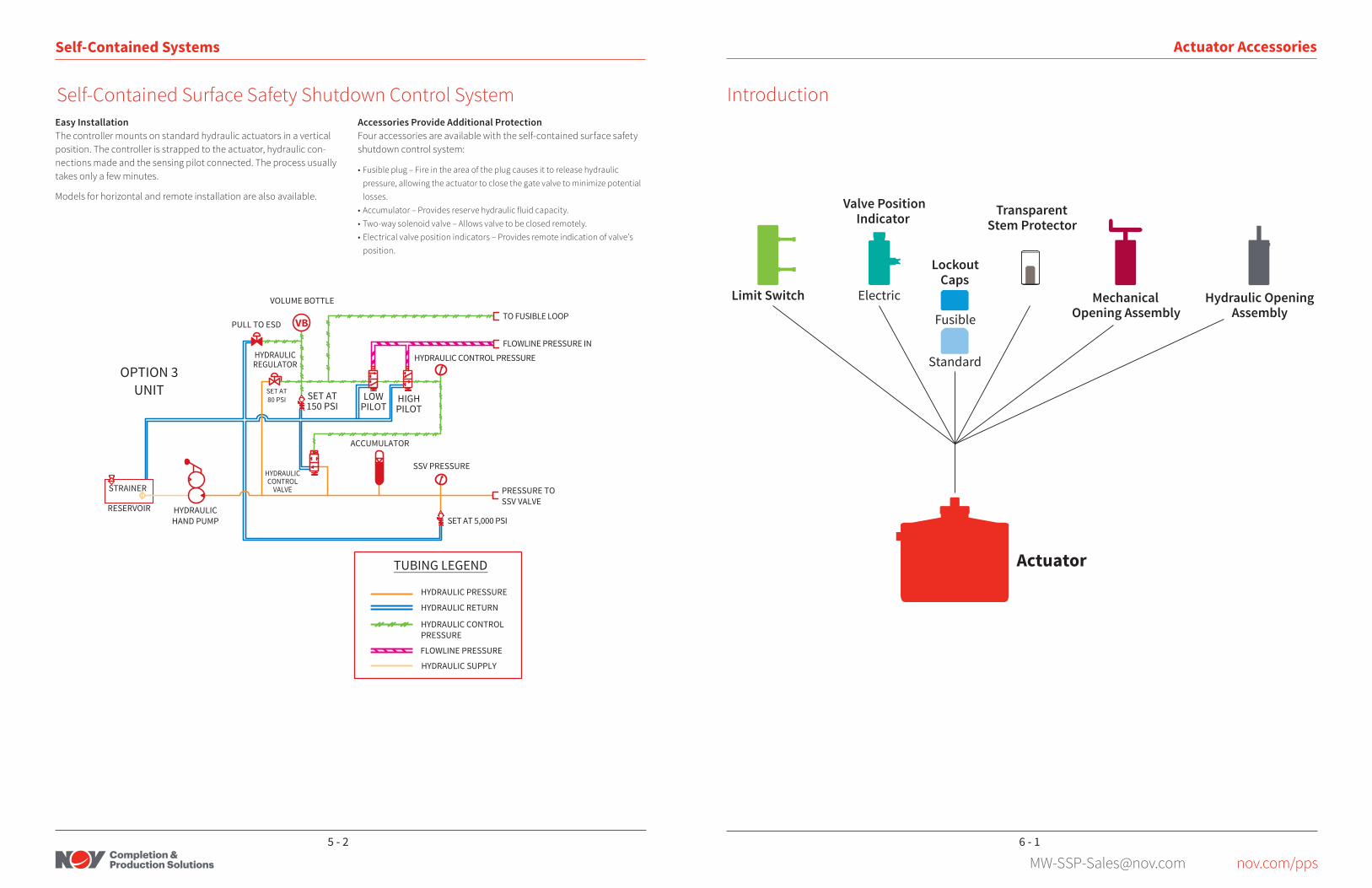
Self-Contained Systems
Self-Contained Surface Safety Shutdown Control SystemEconomical Protection for Remote WellsThe compact, self-contained hydraulic surface safety control system was designed specifically for wells in areas where power and instru-ment air or gas are not available .
• Designed to close the gate valve automatically when abnormal pressures are detected . Optional fusion plug provides shut-in protection in case of fire.
• System and actuator can be installed quickly .• Can be retrofitted to existing actuators in a matter of minutes. Costly spe-
cial actuators are not required .• Uses standard, off-the-shelf components, reducing acquisition cost.• Minimum number of components keeps initial and maintenance costs low .• Can be mounted on actuator or remote .
The system works with reverse-acting gate valves from most manufacturers and is designed for 2 to 4-in . actuators with working pressures to 5,000 psi .
The self-contained system includes a pressure-sensing pilot, con-trols, hand pump, and hydraulic reservoir . Operating the hand pump pressures the actuator which opens the gate valve . The system main-tains hydraulic pressure on the actuator to keep the valve open . If the integral pilot senses abnormal pressure, it opens, causing hydraulic fluid to exhaust from the actuator and the gate valve to close.
Hydraulic fluid exhausts into the integral reservoir, eliminating a potential pollution problem .
Hydraulic Self-Contained Safety System
5 - 14 - 10
[email protected] nov.com/pps
Self-Contained Systems
Self-Contained Surface Safety Shutdown Control SystemAccessories Provide Additional ProtectionFour accessories are available with the self-contained surface safety shutdown control system:
• Fusible plug – Fire in the area of the plug causes it to release hydraulic pressure, allowing the actuator to close the gate valve to minimize potential losses .
• Accumulator – Provides reserve hydraulic fluid capacity.• Two-way solenoid valve – Allows valve to be closed remotely .• Electrical valve position indicators – Provides remote indication of valve’s
position .
SET AT80 PSI
VOLUME BOTTLE
PULL TO ESD
HYDRAULICREGULATOR
STRAINER
RESERVOIR
ACCUMULATOR
SSV PRESSURE
TO FUSIBLE LOOP
OPTION 3UNIT
TUBING LEGEND
FLOWLINE PRESSURE
HYDRAULIC SUPPLY
SET AT150 PSI
FLOWLINE PRESSURE INHYDRAULIC CONTROL PRESSURE
LOWPILOT
HIGHPILOT
HYDRAULICCONTROL
VALVE PRESSURE TOSSV VALVE
SET AT 5,000 PSIHYDRAULICHAND PUMP
HYDRAULIC PRESSURE
HYDRAULIC RETURN
HYDRAULIC CONTROLPRESSURE
VB
Easy InstallationThe controller mounts on standard hydraulic actuators in a vertical position . The controller is strapped to the actuator, hydraulic con-nections made and the sensing pilot connected . The process usually takes only a few minutes .
Models for horizontal and remote installation are also available .
Actuator Accessories
Introduction
Valve PositionIndicator Transparent
Stem Protector
MechanicalOpening Assembly
Electric
LockoutCaps
Fusible
Standard
Actuator
Limit Switch Hydraulic OpeningAssembly
6 - 15 - 2

[email protected] nov.com/pps
Actuator Accessories
Mechanical Reopening AssemblyClockwise rotation of the hand-wheel in this unit forces the valve stem down to open the valve . A roller thrust bearing is used to reduce the turning effort. The threaded opening stem of the unit is not exposed to well fluids. This type of reopening assembly is limited in load . It should only be used with differential pressures up to 3,000 psi across the valve.
Mechanical Reopening Assembly
Thread StrokeDimension
A (in.) B (in.) C (in.) D (in.) Weight (lb.)
2¾-8UN 3.3 18.7 3.23 1.4 15.0 25
2¾-8UN 5.2 21.0 3.2 1.4 20.0 32
5-4 ACME 4.9 24.6 5.5 1.9 20.0 40
5-4 ACME 7.5 22.2 5.5 1.9 20.0 50
Mechanical Opening Jack
Actuator Accessories
Lockout CapsLockout caps are used to lock the safety valve out of service in its open position . During safety system maintenance or wireline operations, the cap is screwed onto the actuator’s top cylinder thread .
Two types are available: standard and fusible . A standard one-piece model is supplied with most pneumatic actuators . Also available is a fusible lockout cap designed to melt under extreme heat which permits the valve to close in the event of a fire. The fusible cap is available with a release temperature of 400°F .
Lockout Caps
Connection Relative Temperature (°F) OD (in .) Length (in .)
2¾-8UN 400 4.48 1.84
5-4 ACME 400 8.52 2.72
Fusible Lockout Cap
6 - 36 - 2

[email protected] nov.com/pps
Actuator Accessories
Electric Valve Position IndicatorsElectric valve position indicators complement the safety valve actuators .
Benefits• Explosion-proof rated for use in extremely hazardous locations .
(UL Class 1, Division 1, CSA listed .)• Gives positive open or closed position as position indicator stem
moves in conjunction with gate in the valve body .• Auxiliary equipment can be adapted to the indicator .• Rated at 10 watts AC resistive and 250 volts maximum . Higher
ratings available on special order .
Electric Position Indicator
Stem Thread Cylinder Thread Net Length (in .) OD (in .)Stroke (in .)
Weight (lb .)Maximum Minimum
2-3/4-8UN 3/8-16UNC 10.2 3.7 4.20 2.20 25
2-3/4-8UN 3/8-16UNC 12.1 3.7 6.10 4.20 30
4-1/4-8UN 3/8-16UNC 13.1 5.3 7.10 5.20 45
5-4 ACME 3/8-16UNC 14.9 6.0 8.10 5.50 62
Electric Position Indicator
Actuator Accessories
Thread Dimension A(in .)
Dimension B(in .)
2¾ - 8 4.0 5.5
2¾ - 8 3.5 9.0
5 - 4 ACME 6.0 7.3
2¾ - 8 4.0 7.0
5 - 4 ACME* 5.5 9.7
* Acrylic stem cover with metal cylinder attachment.For reference only. Dimensions may change with manufacturer.
Stem Protector
Stem ProtectorThe stem protector is designed to shield the stem against environmental hazards such as paint, mold, and dust buildup, which aids in the longevity of the stem packing and reduces maintenance .
The stem protector screws onto the actuator cylinder . It is made of clear acrylic, so the stem is visible .
Stem Protector
6 - 56 - 4

[email protected] nov.com/pps
Actuator Accessories
Proximity Switch
Size 5/8 in. (15.88 mm) dia. X 3-5/8 in. (92.08 mm) long with 5/8 in.- 18NF X 1-7/8 in. (47.66 mm) threads
Sensing Distance 0.100 in. (2.54 mm) end sensing
Differential 0.40 in. (1.02 mm) approximately
Response Time 8 milliseconds
Temperature Rating -40°F (-40°C) to 221°F (105°C)
Contacts Single pole, double throw, form C, silver cadmium oxide, gold finish
Rating 2 amp at 240 VAC 5mA at 24 VDC (CSA only), 250 VDC at .5 amp resistive (UL only)
Housing Stainless steel
Conduit Outlet 1/2 in.-14 NPT one location
Repeatability 0.0002 in. (0.05 mm) typical
Approvals BASE EFA Certificate No. Ex 89C1233X, Eexd 11C T6, Tamb -30°C + 75°C (T5, Tamb -30°C + 90°C) (T4, Tamb -30°C + 100°C)
Termination 18 in. (457.2 mm) potted in 18 gauge PVC insulated TEW stranded lead wires, rated at 221°F (105°C) 300V UL/CSA listed
Proximity Switch Design Specifications
Actuator Accessories
Valve Size (in .) Maximum Body Pressure (psi)
1-13/16, 2-1/16, 2-9/16 10,000
3-1/8 to 4-1/16 5,000
3-1/8 to 4-1/16 7,000
6 and 8 1,800
6 and 8 740
Hydraulic Operator Recommendations
Hydraulic OperatorHydraulic operators are used to manually operate AU actuators and are available for 1-13/16 in . through 8-in . valves with working pres-sure up to 10,000 psi . The cylinder and pistons are fabricated from 410 stainless steel . The entire unit has been coated for corrosion resistance . (See Figure 1 .)
Figure 1
Piston
BackupRing
Plug
O-Ring
Cylinder
O-Ring
BackupRing
Bushing
The hydraulic operators recommended for various sizes and max-imum body pressures of valves are listed in the table below . (See Figure 2 .)
Figure 2
6 - 76 - 6

[email protected] nov.com/pps
Actuator Accessories
Fusible OperatorsFusible manual operators are used to manually open (or close, depending on customer requirements) a surface safety valve using an AU series actuator . They are available for valves size 1-13/16 in . through 8 in .
Maximum operating (line) pressure for the manual operator is 5,000 psi . Maximum operating line pressure for the hydraulic operator is 10,000 psi .
Actuator Accessories
Fusible Lock-Open CapsTwo types of adjustable fusible lock-open caps are available:
• Type R fusible lock-open cap• Fusible-type lock-open cap
Type R Fusible Lock-Open Cap
The fusible material melts at 400°F allowing the valve to return to its normally closed position . Both types of lock-open caps can be adjusted to make a perfect drift opening of the valve.
The type R fusible lock-open cap has an additional advantage over all other lock-open caps . It can be released manually and immedi-ately in case of emergency allowing the valve to close .
Fusible Lock-Open Cap
6 - 96 - 8

[email protected] nov.com/pps
Actuator Accessories
Hydro-Pneumatic DampenerThis device is used with pneumatic actuators (piston and dia-phragm) to reduce the effects of shock upon opening against valve differential pressure. The dampener has only a minor effect on valve closing times . The dampener is pressure tested for a maxi-mum working pressure of 250 psi .
The dampeners can be used with an actuator mounted horizon-tally or vertically . However, when a double diaphragm actuator is mounted vertically, the dampener must be mounted above the inlet ports of the top actuator section as shown in Figure 1 .
Figure 1: Vertical Mount of Double Diaphragm
All other applications can be mounted as shown in Figure 2 . Always connect supply gas to the highest point of the tank . Connect the supply gas to the exit tank at the lowest point going to the actuator . Two ports are supplied so that the other high port is used as filler and as the location of a pressure safety device .
Secure the tank with either the thread protector (piston) or a mounting bolt (diaphragm) .
Figure 2: Can be Mounted on Top or Either Side — Not Bottom
Fusible Operators
Actuator Accessories
Limit Switch
Actuator Boss Thread Size Actuator Assembly Description
2-8UN THD
9R AUD
13R AUD
18D AUP
2 X 12D AUP
12D AUP
18D AUP
2½-8UN THD
13R AUD
13R AUD
13R AUD
13R AUD
17R AUD
17R AUD
13R AUD
2-8UN THD 18D AUP
AUD and AUP Actuator Applications
Limit Switch
6 - 116 - 10
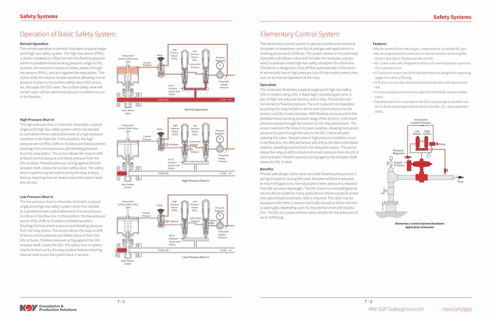
[email protected] nov.com/pps
Safety Systems
Operation of Basic Safety SystemNormal OperationThe normal operation schematic illustrates a typical single point high-low safety system . The high-low sensor (PSHL) is shown installed on a flow line with the flowline pressure within its predetermined working pressure range . In this position, the instrument pressure slows, passes through the sensors (PSHL), and acts against the relay piston . This action shifts the relay to its open position allowing control pressure to pass to the surface safety valve (SSV) actua-tor, and open the SSV valve . The surface safety valve will remain open until an abnormal pressure condition occurs in the flowline.
High Pressure Shut-InThe high pressure shut-in schematic illustrates a typical single point high-low safety system which has reacted to a predetermined undesirable event of a high pressure condition in the flow line. In this position, the high pressure sensor (PSL) shifts to its block and bleed position, blocking instrument pressure, and bleeding pressure from the relay piston. This action allows the relay to shift to block control pressure and bleed pressure from the SSV actuator . Flowline pressure, acting against the SSV actuator shaft, closes the surface safety valve. The safety shut-in system may be locked out by the relay lockout feature, requiring manual reset to place the system back into service .
Low Pressure Shut-InThe low pressure shut-in schematic illustrates a typical single point high-low safety system which has reacted to a predetermined undesirable event of a low pressure condition in the flow line. In this position, the low pressure sensor (PSL) shifts to its block and bleed position, blocking the instrument pressure and bleeding pressure from the relay piston. This action allows the relay to shift to block control pressure and bleed pressure from the SSV actuator . Flowline pressure acting against the SSV actuator shaft, closes the SSV. The safety shut-in system may be locked out by the relay lockout feature requiring manual reset to put the system back in service .
Safety Systems
Elementary Control System ShutdownApplication Schematic
Elementary Control SystemThe elementary control system is used to provide an economical shutdown or blowdown valve for oil and gas well applications in working pressures to 3,000 psi . The system shown in the schematic illustrates a shutdown valve and includes the necessary compo-nents to provide a total high-low safety shutdown for a flow line. The device is designed to shut off flow automatically in the event of abnormally low or high pressure, loss of instrument control pres-sure, or by manual operation of the relay .
OperationThe schematic illustrates a typical single point high-low safety shut-in system using a DG-3 diaphragm-operated gate valve, a pair of high-low pressure sensors, and a relay . The sensors are connected to flowline pressure. The unit is placed into operation by pulling the relay handle to admit instrument pressure to the sensors and DG-3 valve actuator. With flowline pressure within the predetermined working pressure range of the sensors, instrument pressure passes through the sensors to the relay pilot piston . This action maintains the relay in its open position, allowing instrument pressure to pass through the relay to the DG-3 valve actuator, opening this valve . Should a low or high pressure condition occur in the flow line, the affected sensor will shift to the block and bleed position, bleeding pressure from the relay pilot piston . This action allows the relay to shift to block instrument pressure from the DG-3 valve actuator. Flowline pressure acting against the actuator shaft closes the DG-3 valve .
BenefitsThe fail-safe design of the valve uses both flowline pressure and a spring to assist in closing the valve . No external force is required to return the gate to its normal position when pressure is released from the actuator diaphragm . The DG-3 valve is a versatile general service device suited for many applications where a positive action fully open/closed automatic valve is required . The valve may be equipped with either a reverse (normally closed) or direct (normal-ly open) gate, depending upon its required function and installa-tion . The DG-3 is a reduced bore valve suitable for line pressures of up to 3,000 psig .
Features• May be powered from natural gas, compressed air, or bottled (N2) gas .• May be programmed for automatic or manual reset by connecting the
sensors and relay in the appropriate manner .• DG-3 valve is fail-safe, designed to return to its normal position upon loss
of actuator pressure .• ECS pressure sensors are block and bleed devices designed for operating
ranges from 20 to 2,700 psig .• ECR relay is a normally closed block-and-bleed valve with manual over-
ride .• It is not necessary to remove the valve from the line for routine mainte-
nance .• Stainless steel trim is standard in the DG-3 valve and gives excellent ser-
vice in fluids containing limited levels of chlorides, CO2, and suspended solids .
7 - 27 - 1

[email protected] nov.com/pps
Safety Systems
Safety Monitoring and Control SystemsControl expertise extends to the entire safety system . This knowledge is applied to develop and integrate surface-controlled subsurface safety valves, surface safety valves, and production automation equipment .
Safety Control Panels Safety control panels control the operation of surface and sub-surface safety valves . In normal applications, pneumatic control pressure operates the surface safety valve, and hydraulic pressure operates the subsurface safety valve . In most high pressure ap-plications, hydraulic control pressure operates the surface safety valve .
The safety control panel contains all the logic circuits required to properly sequence the opening and closing of both the surface and subsurface safety valves . Stainless steel cabinetry and a weath-er-tight door protect panel-mounted components . Stainless steel fittings, tubing, and components are standard for offshore service.
For single well controls, the hand pump operation is mounted at the front of the unit for easy operation and easy reference of hydraulic gauges during pumping . Operating instructions and a system schematic are mounted on the door for permanent, quick reference .
Features • Provides logic and control for both surface and subsurface safety valves . • Portable, lightweight construction . • Enclosure design provides protection for the panel-mounted compo-
nents and easy maintenance .
Benefits • Surface and subsurface valve control capability provide extra safety for
operating personnel . • Durable construction provides economic, long-term operation . • Field personnel can monitor well pressure with just one glance and accu-
rately adjust pressure limits .
a
b
c
d
e
f
g
h
ij
b
Specifications • Pressure rating: 6,000 psi (41 .37 MPa); 10,000 psi (69 .95 MPa); 15,000 psi (103 .42 MPa) • Temperature rating: 0 to 250°F (-18 to 121 .1°C)
Options • Single or dual hydraulic pumps • Sequential or non-sequential safety valve opening and shut-in • Surface control only or surface and subsurface control • Hydraulic or pneumatic output for surface control • External pilot control or panel-mounted internal pilot control • Standard or H2S service with captured exhaust • Available with or without a telemetry interface
Typical remote-control surface and subsurface safety system components:
a . surface-controlled safety valve b . manual gate valvec . pneumatic surface safety valved . hydraulic surface safety valvee . control line
f . emergency shutdown valveg . fusible plugh . monitor piloti . safety control panelj . low-pressure air or gas source
Safety Systems
Safety Monitoring and Control SystemsAutomated Safety Systems Automated safety systems combine electronic monitoring and intelligent control for both land and offshore operations. These systems are designed to provide well control either from a central field location or from an engineering or operations location hun-dreds of miles away .
Features • Self-contained control unit is placed at or near each well . • High-resolution transducers mounted on the wellhead electronically
monitor conditions . • Controller contains built-in alarms that monitor pressure, temperature,
fire detectors, and erosion probes. The controller also controls the safety valves at the wellhead .
• A master station monitors all wells from a central location with supervi-sory control and data acquisition (SCADA) software.
Benefits • System allows operators to monitor numerous wells economically via a
centralized master station computer . • Unmanned wellsites add an extra measure of safety to operations .
Specifications• Operating pressures: 0 to 15,000 psi (0 to 103 .42 MPa) • Standard temperature rating (others available): Hydraulic systems: -40 to 185°F (-40 to 85°C) Pneumatic systems: 0 to 185°F (-18 to 85°C) • Safety compliance available in intrinsically safe or explosion-proof mod-
els
Options • Emergency shutdown station • Hazardous-gas detectors • Choke control • Non-critical well-parameter monitoring • Solar power • Controls for multi-well platforms or wellhead clusters
Typical wellsite automated safety system components:
a . casing pressure transmitterb . wellhead pressure transmitterc . production choke/actuator assemblyd. flowline temperature transmittere. flowline pressure transmitterf . electrical linesg . hydraulic lines
h . radio systemi . solar power systemj . hydraulic/pneumatic/battery sectionk . electronics sectionl . accumulatorm . surface safety valve
7 - 47 - 3

[email protected] nov.com/pps
Safety Systems
Single well control panels are designed to operate and control the safety valves of a specific well without influencing the status of surrounding wells . A single well control panel is essentially a closed hydraulic system in which the same fluid is continuously used from reservoir to pump, then through a control valve to the safety valve, and back to the reservoir . The panels are designed to provide and control hydraulic pressure required to keep the safety valves open .
Any loss of pressure to the hydraulic or pneumatic lines of the safety system or the reaction of a flowline pilot, an emergency shutdown system (ESD), or a fusible plug will signal the control panel to close the safety valve(s) .
Control panels are complete power units and only require connec-tion to the safety system . They can be designed to perform in any environment .
Single-Well Control Systems
Single-Well Control Panels
Safety Systems
Multi-well hydraulic control panels are designed for safety systems that require operating of, and control for, more than a single well installation . Most of these multi-well control panels use either a removable or integral modular concept .
Each well control module contains the components and gauges essential for basic control of a specific well. Multi-well panels are custom designed and built to fulfill specific customer requirements.
Any kind of control panel can be designed to fulfill our customers needs including: electric, hydraulic, pneumatic, solar, or a combination of sources . Describe your situation and we will put our experience and expertise in safety systems to work for you . You will receive the best possible system to obtain the best possible results .
Multi-Well Control Systems
Multi-Well Control Panels
7 - 67 - 5

[email protected] nov.com/pps
System Components
PRV RelayThe PRV relay is a device which controls high pressure with a lower pilot pressure . Relays are available for both pneumatic and hydraulic control applications . The pneumatic relay is available in a three-way block and bleed convertible to either automatic or manual reset . Pressure ratings are 0 to 375 psi for control pressure and 25 to 250 psi for pilot pressure . The hydraulic relay is available in either two-way bleed only or three-way block and bleed with manual reset only and pressure rating of 150 to 10,000 psi .
OperationAll relays operate in much the same manner . Following is an example of the PRV pneumatic relay operation .
• Manual reset – The manual reset relay will remain in the normal (closed) position until the knob is pulled outward . The handle will remain in the outward position with the application of pilot pressure or with the use of the manual lock-in device . Loss of pilot pressure will allow the stem to move back to the closed position . The relay will remain closed until manually reset by pulling the knob outward . The knob may also be manually pushed inward at any time, even with pilot pressure applied, and it will remain in the closed position .
• Automatic reset – The automatic reset relay is fully responsive to the application of instrument pressure applied to the pilot port . Manual operation will override the pilot pressure in movement to either position . However, if manually closed and if the knob is released, the relay will re-open if pilot pressure is present .
Features• Three-way block and bleed or two-way bleed only • NACE compatible for sour service applications• Large exhaust area for fast shut-in of safety valves• Once actuated, provides means of locking the actuator in the fail-safe
position until manually reset• Provides manual operation of the system for startup or shutdown
PRV Relay Lock-in Assembly PRV Relay
System Components
ESP pressure sensors are designed to detect abnormal operating conditions in a safety system and transmit a signal to perform a specific shutdown function.
The ESP pressure sensor is a highly accurate and reliable device . It can be used as a high or low sensor, or two units can be connected in series and used for both high and low sensing . The combination high and low sensor is called the ESPHL . The ESP sensor has a sensing pressure range of .25 to 20,000 psig .
The pressure controller is a pressure sensor which includes full operation of a sensor and relay combination . It has a manual-type relay valve with manual trip and override capability . The pressure controller is available with a three-way block and bleed hydraulic relay, a two-way normally open hydraulic relay, or a three-way block and bleed pneumatic relay . Sensing pressure range is 1 to 20,000 psig .
Indicator scales are available as an option . This feature allows accurate field adjustment after initial calibration.
OperationAll pressure sensors operate much the same way . Following is an example of ESP sensor operation .
The sensor may be connected for detection of high pressure or low pressure by connecting the input instrument pressure to the appropriate port . When connected to either port, the other port becomes the exhaust port .
When used as a high-pressure sensor, the sensor allows flow through the instrument ports from high inlet to outlet . When the sensing pressure increases to the high-set point, the instrument inlet is blocked, and the outlet is bled to the exhaust port .
When used as a low pressure sensor, the sensor allows flow through the instrument ports from low inlet to outlet as long as the sensed pressure is above the low set pressure . When the sensing pressure decreases to the low set point, the instrument pressure is blocked, and the outlet is bled to the exhaust port .
Features• Sensing pressure range 0 .25 to 20,000 psig• Instrument pressure up to 1480 psi• Differential sensing unit available for sensing range of 0.5 to 40 psid• NACE compatible for sour service applications• Repeatability of within 3% of set point• Dead band maximum 5% of range
ESP Pressure Sensor
ESP Pressure Sensors
8 - 28 - 1

[email protected] nov.com/pps
System Components
ESPHL High-Low Pressure ControllerThe high-low pressure controller is a basic safety system unit which provides a means for programming the automatic operation of a surface safety valve .
The ESP pressure sensors in the unit will sense predetermined high and low pressure limits selected by requirements of the installa-tion . On sensing either of these limits, the unit is designed to close the surface safety valve .
Sensing range of the controller is .5 to 10,000 psi; maximum instru-ment pressure through the sensors to the bottom of the relay is 200 psi; maximum control pressure through the relay is 375 psi .
ESPHL High-Low Pressure Controller
System Components
OperationThe ECS pressure sensor may be used as a high or low pressure sensor by selecting the proper instrument pressure inlet and setting the desired operating pressure .
Preselected pressure settings are made by adjusting the spring force acting against the sensor stem . Once in operation, the sensor is designed to allow instrument pressure to flow from the inlet to outlet until sensing pressure rises or drops beyond predetermined settings . When that happens, the sensor blocks the incoming instrument pres-sure and back-bleeds the downstream pressure to the atmosphere through the alternate port .
Features• Operating pressure range from 20 to 2,700 psi• Three-way block and bleed valve• Designed for 5% repeatability of set point or 5 psi, whichever is greater• Spring may be replaced with instrument and sensing pressures present in
the sensor .• Designed for use with standard service• Corrosion resistant materials• Maximum working pressure of 10,000 psi
Adjustment Cap
Lock Nut
Spring
Body
InstrumentPressureInlet for HighSetting 1/4-in. NPT
InstrumentPressureInlet for LowSetting1/4-in. NPT
Stem
1/2-in. NPT
SensingPressure
Inlet
InstrumentPressureOutlet1/4-in. NPT
ECS Pressure Sensor
Type ECS Pressure Sensor
8 - 48 - 3

[email protected] nov.com/pps
System Components
Erosion ProbeThe erosion probe is available with various wall thicknesses in differ-ent materials to assist in most erosion applications . When information is desired to determine the combined effect of corrosion and erosion, alloy-steel probes may be used . However, it should be noted that this does not ensure correlation because subtle differences in corrosion conditions can be very significant.
Benefits• May be used in almost any size flowline• Is available in stainless material• Various probe wall thicknesses are available to meet most well conditions .
Operating PrincipleIf the erosion probe is eroded, pressure signals are transmitted to an attached pilot or gauge apparatus to shut the safety system or signal an alarm .
Exhaust ofControl LinePressure
Erosion orCorrosion ofProbe
Operated
ECS Pressure Sensor
Erosion Monitor Pilots and Flowline Accessories
System Components
Auxiliary Valves for Sensing EquipmentEmergency shutdown valves are designed to be operated manually to shut down a safety system in an emergency or for routine maintenance . Typical lo-cations for these valves include helicopter decks, rig floors, boat landings, etc. The valves are located in the pilot or ESD control line and are normally used with a relay valve . By pulling out the handle, control pressure is released to the atmosphere from the control line . The control line is designed to activate the relay valve, bleed off control pressure from the safety valve, and allow the safety valve to close .
Emergency Shutdown System
Remote Emergency Shutdown (ESD) Station
8 - 68 - 5

[email protected] nov.com/pps
System Components
Sand Probe Valve
Sand Probe ValveThe sand probe sensor is a three-way block and bleed valve which detects the presence of abrasive material in a flowstream that could cause the piping to be cut out. The valve shifts position when an abrasive gas or liquid erodes the sand probe sufficiently to allow flow-line pressure to act against the sensor’s lower stem . The sand probe instrument pressure working range is from 0 to 250 psi with 1/4-in . NPT connections. The section attached to the flow line has a working pressure range of 100 to 10,000 psi and has a 1/2-in . 14 NPT mounting connection with a 1/4-in . NPT female port for connecting the probe .
OperationThe sand probe sensor is installed at any point in a flow line to detect the affects of abrasive fluid flow. The sand probe provides a manual override to shut in the safety system which also acts as an indicator . The knob is normally in a down position . This allows instrument pres-sure to pass from port A to port B of the sand probe sensor . The sand probe sensor will remain in its open position until abrasive erosion cuts through the sand probe and admits flowline pressure to the sand probe sensor’s lower stem . Line pressure acting against the sand probe sensor’s stem area forces the stem upward .
Flowline pressure is sealed from atmosphere by the lower o-ring, and the metal-to-metal seal is affected between the lower stem, and lower body or sensor stop . Once the lower stem moves up in its sealing position, the three-way block and bleed valve of the main sensor body shifts to block instrument air at port A and back bleeds instrument pressure from port B to port D . This causes downstream safety shut-in components to react to close the SSV safety valve . The sand probe will remain in a locked-out block and bleed position until the sand probe is replaced . The sand probe cannot be overridden and placed back into service with flowline pressure applied to the lower stem . In normal condition (good probe) the three-way block and bleed valve of the sand probe can be pulled out to manually shut in the system but must be pushed downward to its in-service position to reactivate and open the SSV safety valve .
Remote Emergency Shutdown (ESD) Station
System Components
ApplicationFigure 1 shows one type of application installed directly on the flow line. Alternatively, Figure 2 shows the sensor remotely installed .
The assembly provides the means to detect the erosion due to an abrasive fluid in the flow line and signals the safety system to shut in if erosion occurs to a certain level .
Remote Emergency Shutdown (ESD) Station
Figure 1: Typical Application for Sand Probe Mounted on Flow Line
8 - 88 - 7

[email protected] nov.com/pps
System Components
Remote Emergency Shutdown (ESD) StationSand Probe SensorThis flowline erosion monitor can actuate ESD circuits or alarm devices . When sand blast abrasion penetrates the thin-walled sand probe sensor suspended in the flow stream, well fluids penetrating the sensor actuate the sand probe valve which closes the surface safety valve .
Internally supported sensors are available in various wall thick-nesses, connection sizes, and varying length to suit requirements .
Sand Probe Sensor
Low-PressureControl LinePlunger
Flowline
WellPressure
Exhaust ofControl LinePressure
Erosion orCorrosion ofProbe
In Service Operated
Size Connections Available 1/8-in. NPT through 1-in. NPT
Material 316 Stainless Steel
Typical Sensor Wall Thicknesses .020, .025, .030, .035, .050
Sand Probe Specifications
Measure probe length from base of NPT connection .
System Components
Quick Exhaust ValvesHydraulic Quick Exhaust ValvesHydraulic quick exhaust valves are designed to allow quick exhaust of hydraulic pressure from the safety valve actuator upon signal . The valves are designed to be activated whenever pressures up-stream of the quick exhaust are relieved . The valves provide a full opening exhaust near the safety valve .
Operating PrincipleThe operating principle is based upon pressure differential. When back-flow occurs in the control line leading to the quick exhaust valve, upward movement of the flapper seal is designed to pull the valve off seat. With the valve off seat, an unobstructed path is cre-ated for exhausting of control line pressure . Control line pressure will then return to the hydraulic fluid reservoir.
Benefits• Stainless steel construction provides corrosion protection• Clearly marked 1/2-in . NPT ports simplify installation• No adjustments or knobs to complicate installation • Available in 5,000 and 10,000 psi working pressure
Hydraulic Quick Exhaust Valves
8 - 108 - 9

[email protected] nov.com/pps
System Components
Pneumatic quick exhaust valves are offered for two types of service: low-pressure and high-pressure . Pneumatic quick exhaust valves are normally placed in the control line near a pneumatic safety valve .
Operating PrincipleControl pressure is admitted to the quick exhaust valve and flows through to the safety valve . When control pressure is exhausted from the control line, the pressure differential should cause the diaphragm in the quick exhaust valve to move . The valve’s exhaust port is then opened and designed to allow quick exhaust of the control pressure from the safety valve .
Benefits• Allows the safety valve to close at a faster rate than when control pres-
sure is bled off entirely through the monitor pilot• Designed for low pressure (up to 150 psi) control systems or high pres-
sure (up to 500 psi) control systems
Pneumatic Quick Exhaust Valves
Pneumatic Quick Exhaust Valves
System Components
Hydraulic Control ValveThree-Way Normally Closed Hydraulic ControllerThe three-way normally closed panel-mount hydraulic controller is designed to permit manipulation of hydraulic pressures up to 10,000 psi in response to low-pressure pneumatic control circuits . Proper installation of these valves permits automatic and manual pilot circuits to control closing sequences of subsurface safety valves in coordination with surface control systems . The design of the three-way normally closed controller permits use of a common hydraulic supply . Additionally, all connections are 1/4 in . NPT and the override plunger allows operation of the valve when no pilot pressure is available . Air pressure of 125 psi will operate up to 10,000 psi hydraulic .
The override plunger should always be left in the extended posi-tion for automatic service .
*Indicates parts included in a repair kit .
Material 316 Stainless Steel
Operating Temperature -20°F to +250°F
Weight 7 lb.
Size Connections 1/4 in.-18 NPT
Panel Mount Hole 1-1/8 in.
Working PressurePilot Port
Supply, Valve, Exh .
Pilot Port: 0-150 psi/supply, Valve, Exhaust: 10,0000-150 psi
10,000 psi
Pilot Head Diameter 4-5/8 in.
Overall Height 6-1/2 in.
Hydraulic Control Valves
CAUTION
8 - 128 - 11

[email protected] nov.com/pps
Miscellaneous Wellhead and Surface Equipment
Quick Union Tree CapsQuick union tree caps are used to connect the bottom of the wireline valve to the top tree connections . Wells which will require periodic wireline service in christmas trees with flanged components should be ordered from the wellhead manufacturers with the quick union flange-adapter as part of the christmas tree. Adapters are furnished to the wellhead manufacturer with a plug tapped for a valve and pressure gauge and a quick union collar . In order to rig up wireline, the plug and collar are removed and the wireline valve is set in place .
Otis quick union tree caps are designed to minimize rig-up heights when connecting the lubricator to the wellhead . Available in a variety of pressure ratings, these tree caps are offered in sizes for 2-1/16 in. and larger API flanges, and 5 in.-4 to 12 in.-4 Acme quick unions.
Quick Union Tree Cap
Surface Lubricator
Miscellaneous Wellhead and Surface Equipment
Valve/Tree(in .)
Pressure (psi) Service Thread Size (in .)
THD ACMESealbore Diameter
(in .)
2-1/16
5,000 STD 5 - 4 3.500
10,000 STD 5 - 4 3.500
10,000 H₂S 6¼ - 4 4.000
15,000 H₂S 6¼ - 4 4.000
2-9/16
5,000 STD 5 - 4 3.500
10,000 STD 5 - 4 3.500
15,000 STD 5 - 4 3.500
15,000 H₂S 5¾ - 4 4.000
20,000 H₂S 6¼ - 4 4.000
3
5,000 STD 5 - 4 3.500
5,000 H₂S 5¾ - 4 4.000
10,000 STD 5 - 4 3.500
10,000 H₂S 5¾ - 4 4.000
15,000 H₂S 7½ - 4 5.500
4
5,000 STD 6½ - 4 4.750
5,000 H₂S 8⅜ - 4 5.250
10,000 STD 6½ - 4 4.750
10,000 H₂S 8⅜ - 4 5.250
15,000 H₂S 9½ - 4 6.250
5
5,000 STD 8¼ - 4 6.187
5,000 H₂S 9 - 4 6.750
10,000 STD 8¼ - 4 6.187
10,000 H₂S 9 - 4 6.750
15,000 H₂S 12¼ - 4 7.000
6-3/8
5,000 STD 8¾ - 4 7.500
5,000 H₂S 9½ - 4 8.000
10,000 H₂S 11½ - 4 8.250
Standard Quick Union Connection Sizes
Quick Union Tree Caps
9 - 29 - 1

[email protected] nov.com/pps
Corporate Headquarters7909 Parkwood Circle Drive Houston, Texas 77036 USA
National Oilwell Varco has produced this brochure for general information only, and it is not intended for design purposes. Although every effort has been made to maintain the accuracy and reliability of its contents, National Oilwell Varco in no way assumes responsibility for liability for any loss, damage or injury resulting from the use of information and data herein. All applications for the material described are at the user’s risk and are the user’s responsibility.
© 2015 National Oilwell Varco All Rights ReservedD392006078-MKT-001 Rev 01
For SSP product solutions, please contact us on:Email: [email protected] us on: nov.com/pps
Tollway Towers South15660 N. Dallas ParkwayDallas, TX 75248 USAT: 972.421.1401