Embed Size (px)
Citation preview

SURGEON DESIGN TEAM
The ORTHOLOC™ 3Di Ankle Fracture System was developed in conjuction with:
Robert B. Anderson, MDOrthoCarolinaCharlotte, NC
Gregory C. Berlet, MDOrthopedic Foot and Ankle CenterColumbus, OH
Bruce E. Cohen, MDOrthoCarolinaCharlotte, NC
W. Hodges Davis, MDOrthoCarolinaCharlotte, NC
Christopher F. Hyer, DPMOrthopedic Foot and Ankle CenterColumbus, OH
Carroll P. Jones, MDOrthoCarolinaCharlotte, NC
Thomas H. Lee, MDOrthopedic Foot and Ankle CenterColumbus, OH
ORTHOLOC™ 3DiAnkle Fracture System
SURGICAL TECHNIQUE

Proper surgical procedures and techniques are the responsibility of the medical professional. The following guidelines are furnished for information purposes only. Each surgeon must evaluate the appropriateness of the procedures based on his or her personal medical training and experience. Prior to use of the system, the surgeon should refer to the product package insert for complete warnings, precautions, indications, contraindications and adverse effects. Package inserts are also available by contacting Wright Medical Technology, Inc.
Contents
Chapter 1 4 Introduction
5 Intended Use
Chapter 2 6 Device Description
7 Instrument/Implant Color Coding System
8 Implant Selection: Plates
10 Implant Selection: Screws
Chapter 3 11 Surgical Procedure
12 Incision
12 Fracture Reduction
13 Lag Screw
13 Fully Threaded Screw Lag Technique
14 Determining Screw Length
14 Countersink
14 Screw Insertion
14 Torque Limiting Driver Handle
15 Provisional Fixation
15 In Situ Contouring
15 Plate Contouring
16 Locking Screws
17 Compression Slots
17 Syndesmosis Fixation
Chapter 4 18 Ordering Information
Chapter 5 24 Screw Quick Guide
3
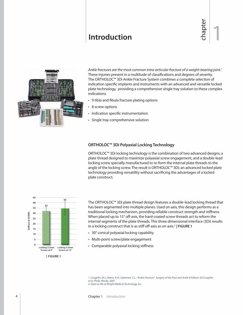
Ankle fractures are the most common intra-articular fracture of a weight-bearing joint.1 These injuries present in a multitude of classifications and degrees of severity. The ORTHOLOC™ 3Di Ankle Fracture System combines a complete selection of indication specific implants and instruments with an advanced and versatile locked plate technology, providing a comprehensive single tray solution to these complex indications.
ORTHOLOC™ 3Di Polyaxial Locking Technology
ORTHOLOC™ 3Di locking technology is the combination of two advanced designs; a plate thread designed to maximize polyaxial screw engagement, and a double-lead locking screw specially manufactured to re-form the internal plate threads to the angle of the locking screw. The result is ORTHOLOC™ 3Di; an advanced locked plate technology providing versatility without sacrificing the advantages of a locked plate construct.
The ORTHOLOC™ 3Di plate thread design features a double-lead locking thread that has been segmented into multiple planes. Used on axis, this design performs as a traditional locking mechanism, providing reliable construct strength and stiffness. When placed up to 15° off-axis, the hard-coated screw threads act to reform the internal segments of the plate threads. This three dimensional interface (3Di) results in a locking construct that is as stiff off-axis as on-axis.2 | FIGURE 1
1chap
ter
Introduction
Chapter 1 Introduction4
45
40
35
30
25
20
15
10
5
0
Sti
ffn
ess
K (
N/M
M)
Locking 3.5mm
Screws at 0°Locking 3.5mm
Screws at 15°
33
35
| FIGURE 1
1. Coughlin, M.J.; Mann, R.A.; Saltzman, C.L.; “Ankle Fracture”. Surgery of the Foot and Ankle 8 Edition. Ed.Coughlin et al. Philly: Mosby, 20072. Data on file at Wright Medical Technology, Inc.

Chapter 1 Introduction
Intended UseIndications
Wright’s ORTHOLOC™ 3Di Ankle Plating System is intended for fixation of fractures, osteotomies, and non-unions of the distal tibia and fibula such as:
Lateral Malleolar Fractures
ORTHOLOC™ 3Di locking screws are intended for use with Wright’s ORTHOLOC™ 3Di Plating Systems of the same base material.
ORTHOLOC™ Bone Screws are indicated for use in bone reconstruction, osteotomy, arthrodesis, joint fusion, fracture repair, and fracture fixation, appropriate for the size of the device.
Wright’s washers are intended to prevent a screw head from breaking through the cortex of the bone by distributing the forces/load over a large area when used for fracture fixation of bone fragments.
Contraindications
Patients should be warned of these contraindications:
Refer to package insert 142058 for complete warnings, precautions, indications, contraindications and adverse effects.
Introduction
5

Chapter 2 Device Description6
2chap
ter
Device Description
In Situ Plate Benders
6 Cannulated Screw Instrumentation
3
4 7
5
2
6
1 Left Fibula Plates 3 Right Fibula Plates
4 Left Tibia Plates
7 Right Tibia Plates
5 Universal Plates
1
2 Wires / Drills / Drivers

Instrument/Implant Color Coding System:
The ORTHOLOC™ 3Di Ankle Fracture System features an instrument and implant color coding system to increase O.R. efficiency and speed. After choosing the appropriate screw for a given application, select the drill and drill guide with the corresponding color coded markings. | FIGURE 2
Chapter 2 Device Description 7
2.7mm Locking / Plate Cortical Full 10-18mm 2.0mm No Grey3.5mm Locking / Plate Cortical Full 10-60mm 2.8mm No Purple3.5mm Low-Profile Bone Cortical Full 10-60mm 2.5mm Yes Bronze3.5mm Bone Cortical Full 10-60mm 2.5mm Yes Bronze4.0mm Bone Cortical Full 24-60mm 2.8mm Yes Gold4.0mm Bone Cancellous Full 12-60mm 2.5mm Yes Green4.0mm Bone Cancellous Partial 20-60mm 2.5mm No Green4.0mm Bone / Cannulated Cancellous Partial 20-60mm 3.0mm No Blue
Diameter Type Thread Thread Available Pre-Drill Over-Drill Color Type Length Diameter Available Code
*All screws feature a universal T-15 drive
mechanism
Screw/Drill Bit Quick Guide
| FIGURE 2
Chapter 2 Device Description8
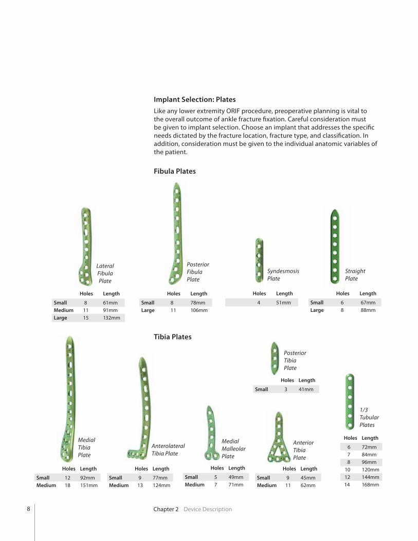
Implant Selection: Plates
Like any lower extremity ORIF procedure, preoperative planning is vital to the overall outcome of ankle fracture fixation. Careful consideration must be given to implant selection. Choose an implant that addresses the specific needs dictated by the fracture location, fracture type, and classification. In addition, consideration must be given to the individual anatomic variables of the patient.
Fibula Plates
Tibia Plates
Lateral Fibula Plate
Posterior Fibula Plate
Syndesmosis Plate
Straight Plate
Holes Length
Small 8 61mmMedium
Large 15 132mm
Holes Length
Small 8 78mmLarge 11 106mm
Holes Length
4 51mm Holes Length
Small 6 67mmLarge 8 88mm
Holes Length
Small
Medium 18 151mm
Medial Tibia Plate
Anterolateral Tibia Plate
Medial Malleolar Plate
Anterior Tibia Plate
Holes Length
Small
Medium 13 124mm
Holes Length
Small
Medium 7 71mm
Holes Length
Small
Medium 11 62mm
Posterior Tibia Plate
Holes Length
Small 3 41mm
1/3 Tubular Plates
Holes Length
6 72mm 7 84mm
10 120mm 12 144mm 14 168mm

Chapter 2 Device Description
Implant Selection
Use the following chart to assist with implant selection:
Lateral Malleolar Fractures X X X
Syndesmosis Injuries X X
Medial Malleolar Fractures X X
Bi-Malleolar Fractures X X X X X
Tri-Malleolar Fractures X X X X X X
Posterior Malleolar Fractures X X
Distal Anterior Tibia Fractures X X
of the Medial Malleolous X X
Pilon Fractures *X *X X X X X X X
Distal Tibia Shaft Fractures X X X
Distal Fibula Shaft Fractures X X X X
Distal Tibia Periarticular Fractures X X X
Lateral Posterior Syndesmosis Universal Medial Anterolateral Medial Anterior Posterior Fibula Fibula Straight Tibia Malleolar Delta Tibia
1/3 tubular plates can be contoured to meet the anatomic demands of multiple ankle fracture types and classifications. Use the plate bending irons or threaded bending bars provided in the system to modify the plate as needed.
Proper surgical procedures and techniques are the responsibility of the medical professional. Each surgeon must evaluate the appropriateness of the product and procedure used based on personal medical training and experience.
* When fibula fractures also occur with indicated fracture type.

10 Chapter 2 Device Description
Implant Selection: Screws
The ORTHOLOC™ 3Di locking hole has been designed to provide the surgeon with a broad range of fixation options. All 3Di locking holes will accept 2.7mm and 3.5mm locking screws. Locking screws can be locked on-axis with the plate threads or up to 15 degrees off-axis in any direction (30 degree conical). | FIGURE 3 In addition, six options of 3.5mm and 4.0mm non-locking screws can be used in all 3Di locking holes.
Screw diameter and size are determined by anatomy and fixation goals. All screws are self-tapping, but do require the use of color coded pre-drills and provided instrumentation. Additionally, 3.5 and 4.0mm over-drills are provided in the system for use in a lag technique.
2.7mm Locking Screw: 3.5mm Locking Screw: 3.5mm Low-Profile Screw:3 5 L ki S
3.5mm Cortical Bone Screw: 4.0mm Cortical Bone Screw: 4.0mm Cancellous Bone Screw:
4.0mm Cancellous Bone Screw: 4.0mm Cannulated Bone Screw:
15o
15o
| FIGURE 3
Bone Screw Washers:Washers are intended to prevent a screw head from breaking through the cortex of the bone by distributing the forces/load over a large area

3chap
ter
Surgical Procedure

Chapter 3 Surgical Procedure12
Incision
Several incision options are available for ankle fractures. Preoperative
Incision location should take into account the fracture type and anatomy.
Fracture Reduction
Anatomic reduction is performed and length restored. In cases of comminution and bone loss, the contralateral ankle is used as a reference for accuracy. Temporary fixation of the bone is achieved using the bone reduction forceps
taken to ensure that the location of the forceps do not interfere with the planned
A
B
C
D
E
F
G
Fracture Reduction Instrumentation
A Small, curved periosteal elevator 5362000004
B Bone fragment pick 5202000008
C Serrated bone forceps 5882000040
D Pointed bone forceps 5882000045
E Pointed/Serrated forceps 5882000080
G Malleolar Reduction Forceps 5882000050

Chapter 3 Surgical Procedure 13
Lag Screw
Fully Threaded Screw Lag Technique
Based on the desired screw diameter and type, | FIGURE 4 drill the near cortex of the bone through the over-drill guide using the 3.5 or 4.0mm over-drills. This hole should be drilled as perpendicular to the fracture line as possible to achieve maximum compression. Stop drilling just as the drill passes the near side of the fracture line.
Insert the color coded pre-drill insert guide into the corresponding over-drill guide hole | FIGURE 5 or directly into the created bone hole. Finish the hole using the correct pre-drill through the pre-drill insert guide.
Diameter Thread Thread Available Pre-drill Color
Type Length Lengths Code
3.5mm Cortical/Low-Profile Full 10-60mm 2.5mm Bronze
3.5mm Cortical Full 10-60mm 2.5mm Bronze
4.0mm Cortical Full 24-60mm 2.8mm Gold
NOTE: All over-drill instruments are colored dark grey.
In many cases, the use of a fully or partially threaded lag screw is desired for fracture compression and stabilization. The ORTHOLOC™ 3Di Ankle Fracture System is equipped with multiple lag screw options and corresponding instrumentation to address the unique requirements of most distal tibia and fibula fracture types and classifications.
| FIGURE 4
| FIGURE 5
Lag Screw Instruments
3.5/4.0mm Drill Guide 58873540
2.5mm Drill Insert 58810035
2.5mm Drill Insert 58870040
2.8mm Drill Insert 58870140

14 Chapter 3 Surgical Procedure
Lag Screw
Determining Screw Length
Screw length can be determined with the drill and drill guides. Use the appropriate drill to penetrate through the proximal cortex and continue until the distal cortex is reached.
Stop drilling just as the distal cortex of the bone is penetrated and note where the screw length reference on the drill meets the drill guide. | FIGURE 6
As an alternative, a traditional screw depth gauge has also been provided in the system.
Countersink
All ORTHOLOC™ non-locking bone screws can be countersunk into the bone to decrease cortical stress and reduce head prominence. A 6mm solid countersink has been provided in the system for all solid core bone screws. In addition, a 6mm cannulated countersink is provided for the 4.0mm cannulated bone screw.
Place the appropriate countersink in the created bone hole or over the 1.2mm
the screw head. Care should be taken to not over countersink the bone.
Screw Insertion
Insert the desired screw, closely observing the compression along the fracture line. Reduction forceps are removed before final tightening of the lag screw. Final tightening should be performed using a two-finger technique.
Torque Limiting Driver Handle
The ORTHOLOC™ 3Di Ankle Fracture System is provided standard with a torque limiting driver handle. | FIGURE 7 This driver handle has been calibrated to provide the ability to seat all 3Di locking and non-locking screws in all appropriate conditions while avoiding the risk of applying more torque than required. Once the driver handle has reached the maximum allowable torque, an audible click will be heard. Stop driving the screw once the torque limiting driver handle has reached the maximum allowable torque level.
Screw length can be determined with the drill and drill guides.
| FIGURE 6
Depth Gauge 536200016
6mm Countersink 58870002
6mm Cannulated Countersink DSDS1060
Star 15 Driver 58861T15
Torque Limiting Driver Handle 58871012
| FIGURE 7

15Chapter 3 Surgical Procedure
1.4mm temporary fixation pins can be placed in the pin holes on selected plates or through any locking hole to achieve provisional plate fixation.
| FIGURE 8
Plate Fixation
In Situ Contouring
Use of the in situ benders | FIGURE 10 should be limited to the medial malleolar plates. Thread the bender into either of the distal plate holes, ensuring full engagement to the plate threads. Lever the bender down, contouring the plate
| FIGURE 9
If the removal of one or both of the distal tabs is desired, lever the instrument in a back-and-forth motion until the tabs snaps-off from the plate. The tab should break away cleanly along the scored line found on the reverse side of the plate.
Plate Contouring
The ORTHOLOC™ 3Di Ankle Fracture plates have been designed to match the anatomic contours of the distal fibula and tibia. In most cases, inter-operative plate contouring will not be necessary. In cases of bone deformity or abnormalities some contouring may be required.
Use the plate bending irons provided in the system | FIGURE 10 to slightly modify plate contours as needed. Multiple slot widths within the benders are available to accommodate all plate types and thicknesses. Care should be taken to avoid over-bending or bending in a back-and-forth motion to prevent stress risers.
Lever the bender down, contouring the plate flush to the host bone.
A
B
| FIGURE 10
| FIGURE 9
A. Slotted Plate Benders
B. In Situ Plate Benders
Provisional Fixation
Place the chosen ORTHOLOC™ 3Di Ankle Fracture plate on the bone, ensuring adequate points of fixation can be achieved on all sides of the fracture line/s. 1.4mm temporary fixation pins can be placed in the pin holes on selected plates or through any locking hole to achieve provisional plate fixation. | FIGURE 8
Fluoroscopy should be used to verify accurate plate placement.
Slotted Plate Benders 58872031
In situ Plate Benders 58870003
16 Chapter 3 Surgical Procedure
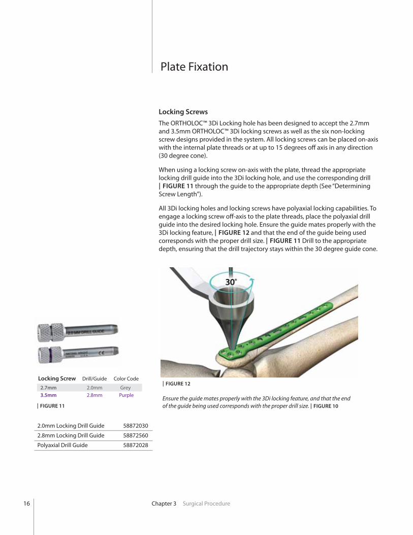
Locking Screws
The ORTHOLOC™ 3Di Locking hole has been designed to accept the 2.7mm and 3.5mm ORTHOLOC™ 3Di locking screws as well as the six non-locking screw designs provided in the system. All locking screws can be placed on-axis with the internal plate threads or at up to 15 degrees off axis in any direction (30 degree cone).
When using a locking screw on-axis with the plate, thread the appropriate locking drill guide into the 3Di locking hole, and use the corresponding drill | FIGURE 11 through the guide to the appropriate depth (See “Determining Screw Length”).
All 3Di locking holes and locking screws have polyaxial locking capabilities. To engage a locking screw off-axis to the plate threads, place the polyaxial drill guide into the desired locking hole. Ensure the guide mates properly with the 3Di locking feature, | FIGURE 12 and that the end of the guide being used corresponds with the proper drill size. | FIGURE 11 Drill to the appropriate depth, ensuring that the drill trajectory stays within the 30 degree guide cone.
Locking Screw Drill/Guide Color Code
2.7mm 2.0mm Grey 3.5mm 2.8mm Purple Ensure the guide mates properly with the 3Di locking feature, and that the end
of the guide being used corresponds with the proper drill size. | FIGURE 10
| FIGURE 12
| FIGURE 11
Plate Fixation
2.0mm Locking Drill Guide 58872030
2.8mm Locking Drill Guide 58872560
Polyaxial Drill Guide 58872028
17Chapter 3 Surgical Procedure
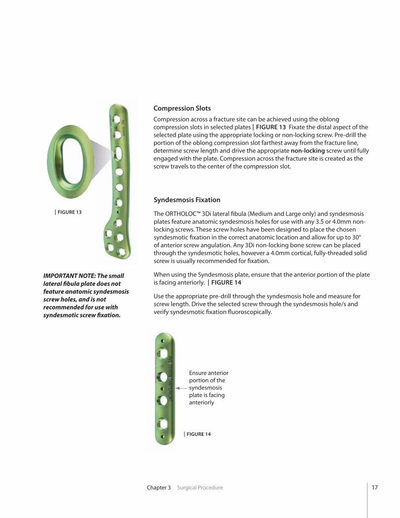
Syndesmosis Fixation
The ORTHOLOC™ 3Di lateral fibula (Medium and Large only) and syndesmosis plates feature anatomic syndesmosis holes for use with any 3.5 or 4.0mm non-locking screws. These screw holes have been designed to place the chosen syndesmotic fixation in the correct anatomic location and allow for up to 30° of anterior screw angulation. Any 3Di non-locking bone screw can be placed through the syndesmotic holes, however a 4.0mm cortical, fully-threaded solid screw is usually recommended for fixation.
When using the Syndesmosis plate, ensure that the anterior portion of the plate is facing anteriorly. | FIGURE 14
Use the appropriate pre-drill through the syndesmosis hole and measure for screw length. Drive the selected screw through the syndesmosis hole/s and
Ensure anterior portion of the syndesmosis plate is facing anteriorly
Compression Slots
Compression across a fracture site can be achieved using the oblong compression slots in selected plates | FIGURE 13 Fixate the distal aspect of the selected plate using the appropriate locking or non-locking screw. Pre-drill the portion of the oblong compression slot farthest away from the fracture line, determine screw length and drive the appropriate non-locking screw until fully engaged with the plate. Compression across the fracture site is created as the screw travels to the center of the compression slot.
| FIGURE 13
| FIGURE 14
IMPORTANT NOTE: The small lateral fibula plate does not feature anatomic syndesmosis screw holes, and is not recommended for use with syndesmotic screw fixation.

18 Chapter 4 Ordering Information
Ordering Information
LATERAL FIBULA PLATE
Part Number Description
5888101L LATERAL FIBULA PLATE LEFT SM
5888101R LATERAL FIBULA PLATE RIGHT SM
5888102L LATERAL FIBULA PLATE LEFT MD
5888102R LATERAL FIBULA PLATE RIGHT MD
5888103L LATERAL FIBULA PLATE LEFT LG
5888103R LATERAL FIBULA PLATE RIGHT LG
POSTERIOR FIBULA PLATE
Part Number Description
5888201L POSTERIOR FIBIA PLATE LEFT SM
5888201R POSTERIOR FIBIA PLATE RIGHT SM
5888203L POSTERIOR FIBIA PLATE LEFT LG
5888203R POSTERIOR FIBIA PLATE RIGHT LG
SYNDESMOSIS PLATE
Part Number Description
58883010 SYNDESMOSIS PLATE
MEDIAL MALLEOLAR PLATE
Part Number Description
58885010 MEDIAL MALLEOLAR PLATE SM
58885030 MEDIAL MALLEOLAR PLATE LG
STRAIGHT PLATE
Part Number Description
58884060 Universal Straight Plate, 6 Hole
58884080 Universal Straight Plate, 8 Hole
4chap
ter
ANTERIOR TIBIA DELTA PLATE
Part Number Description
58886010 ANTERIOR TIBIA DELTA PLATE SM
58886030 ANTERIOR TIBIA DELTA PLATE LG
ANTEROLATERAL TIBIA PLATE
Part Number Description
5888701L ANTEROLATERAL TIBIA PLATE LT SM
5888701R ANTEROLATERAL TIBIA PLATE RT SM
5888702L ANTEROLATERAL TIBIA PLATE LT MD
5888702R ANTEROLATERAL TIBIA PLATE RT MD
MEDIAL TIBIA PLATE
Part Number Description
5888801L MEDIAL TIBIA PLATE LEFT SM
5888801R MEDIAL TIBIA PLATE RIGHT SM
5888802L MEDIAL TIBIA PLATE LEFT MD
5888802R MEDIAL TIBIA PLATE RIGHT MD
POSTERIOR TIBIA PLATE
Part Number Description
POSTERIOR TIBIA PLATE
1/3 TUBULAR PLATE
Part Number Description
58880006 6 HOLE 1/3 TUBULAR PLATE
58880007 7 HOLE 1/3 TUBULAR PLATE
58880008 8 HOLE 1/3 TUBULAR PLATE
58880010 10 HOLE 1/3 TUBULAR PLATE
58880012 12 HOLE 1/3 TUBULAR PLATE
58880014 14 HOLE 1/3 TUBULAR PLATE

Chapter 4 Ordering Information
2.7MM LOCKING SCREW
Part Number Description
58802710 2.7X10MM
58802712 2.7X12MM
58802714 2.7X14MM
58802716 2.7X16MM
58802718 2.7X18MM
3.5MM LOCKING SCREW
Part Number Description
58803510 3.5 X 10MM
58803512 3.5 X 12MM
58803514 3.5 X 14MM
58803516 3.5 X 16MM
58803518 3.5 X 18MM
58803520 3.5 X 20MM
58803522 3.5 X 22MM
58803524 3.5 X 24MM
58803526 3.5 X 26MM
58803528 3.5 X 28MM
58803530 3.5 X 30MM
58803532 3.5 X 32MM
58803534 3.5 X 34MM
58803536 3.5 X 36MM
58803538 3.5 X 38MM
58803540 3.5 X 40MM
58803542 3.5 X 42MM
58803544 3.5 X 44MM
58803546 3.5 X 46MM
58803548 3.5 X 48MM
58803550 3.5 X 50MM
58803555 3.5 X 55MM
58803560 3.5 X 60MM
5
3.5MM LOW-PROFILE CORTICAL SCREW
Part Number Description58813510 3.5 X 10MM
58813512 3.5 X 12MM
58813514 3.5 X 14MM
58813516 3.5 X 16MM
58813518 3.5 X 18MM
58813520 3.5 X 20MM
58813522 3.5 X 22MM
58813524 3.5 X 24MM
58813526 3.5 X 26MM
58813528 3.5 X 28MM
58813530 3.5 X 30MM
58813532 3.5 X 32MM
58813534 3.5 X 34MM
58813536 3.5 X 36MM
58813538 3.5 X 38MM
58813540 3.5 X 40MM
58813542 3.5 X 42MM
58813544 3.5 X 44MM
58813546 3.5 X 46MM
58813548 3.5 X 48MM
58813550 3.5 X 50MM
58813555 3.5 X 55MM
58813560 3.5 X 60MM

20 Chapter 4 Ordering Information
3.5MM CORTICAL SCREW
Part Number Description3.5X10MM
3.5X12MM
3.5X14MM
3.5X16MM
3.5X18MM
3.5X20MM
3.5X22MM
3.5X24MM
3.5X26MM
3.5X28MM
3.5X30MM
3.5X32MM
3.5X34MM
3.5X36MM
3.5X38MM
3.5X40MM
3.5X42MM
3.5X44MM
3.5X46MM
3.5X48MM
3.5X50MM
3.5X55MM
3.5X60MM
4.0MM CORTICAL SCREW
Part Number Description
4.0X24MM
4.0X26MM
4.0X28MM
4.0X30MM
4.0X35MM
4.0X40MM
4.0X45MM
4.0X50MM
4.0X55MM
4.0X60MM
4.0MM CANCELLOUS/FULL SCREW
Part Number Description
4.0X12mm
4.0X14mm
4.0X16mm
4.0X18mm
4.0X20mm
4.0X22mm
4.0X24mm
4.0X26mm
4.0X28mm
4.0X30mm
4.0X35mm
4.0X40mm
4.0X45mm
4.0X50mm
4.0X55mm
4.0X60mm
4.0MM CANCELLOUS PARTIAL SCREW
Part Number Description
4.0X20mm
4.0X22mm
4.0X24mm
4.0X26mm
4.0X28mm
4.0X30mm
4.0X35mm
4.0X40mm
4.0X45mm
4.0X50mm
4.0X55mm
4.0X60mm

21Chapter 4 Ordering Information
4.0MM HEADED CANNULATED / PARTIAL SCREW
Part Number Description
D1N40020S 4.0 X 20MM
D1N40022S 4.0 X 22MM
D1N40024S 4.0 X 24MM
D1N40026S 4.0 X 26MM
D1N40028S 4.0 X 28MM
D1N40030S 4.0 X 30MM
D1N40032S 4.0 X 32MM
D1N40034S 4.0 X 34MM
D1N40036S 4.0 X 36MM
D1N40038S 4.0 X 38MM
D1N40040S 4.0 X 40MM
D1N40042S 4.0 X 42MM
D1N40044S 4.0 X 44MM
D1N40046S 4.0 X 46MM
D1N40048S 4.0 X 48MM
D1N40052S 4.0 X 52MM
D1N40056S 4.0 X 56MM
D1N40060S 4.0 X 60MM
CONSUMABLE INSTRUMENTS
Part Number Description
58850020 DRILL BIT 2.0MM X 24MM
58850025 DRILL BIT 2.5MM X 60MM
58850028 DRILL BIT 2.8MM X 60MM
58850035 DRILL BIT 3.5MM X 60MM
58850040 DRILL BIT 4.0MM X 60MM
DSDS1060
58870002
58850030 DRILL BIT 3.0MM X 60MM CANN
58820024 TEMP FIXATION PIN 1.4MM LG
DSDS1014
DSDS0015
58861T15
5881003540 WASHER 3.5 / 4.0MM SCREW
INSTRUMENTS
Part Number Description
5882000040 REDUCTION FORCEPS SERRATED
5882000045 REDUCTION FORCEPS POINTED
5882000050 MALLEOLAR REDUCTION FORCEPS
5882000080 REDUCTION FORCEPS PNT/SERRATED
5882000055
58872030
58872560
58872025 DRILL GUIDE 2.0 / 2.5
58872830 DRILL GUIDE 2.8 / 3.0
58873540 DRILL GUIDE 3.5 / 4.0
58870000
58810035 DRILL GUIDE 2.5MM INSERT
58870040 DRILL GUIDE 2.5MM INSERT
58870140 DRILL GUIDE 2.8MM INSERT
5362000160 DEPTH GAUGE 60MM
DSDS0006 DEPTH GAUGE SMALL SCREW
58871012
41112017
58872031 SLOTTED PLATE BENDER
58870003 THREADED BENDING IRON
5362000004
5202000008
58872028
5887CASE

22
Notes

™Trademarks and ®Registered marks of Wright Medical Technology, Inc.©2011 Wright Medical Technology, Inc. All Rights Reserved. FA626-1110 R611
Wright Medical Technology, Inc.
5677 Airline RoadArlington, TN USA 38002
800.238.7188www.wmt.com
Wright Medical EMEA
Hoogoorddreef 51101 BA AmsterdamThe Netherlands011.31.20.545.0100www.wmt-emea.com
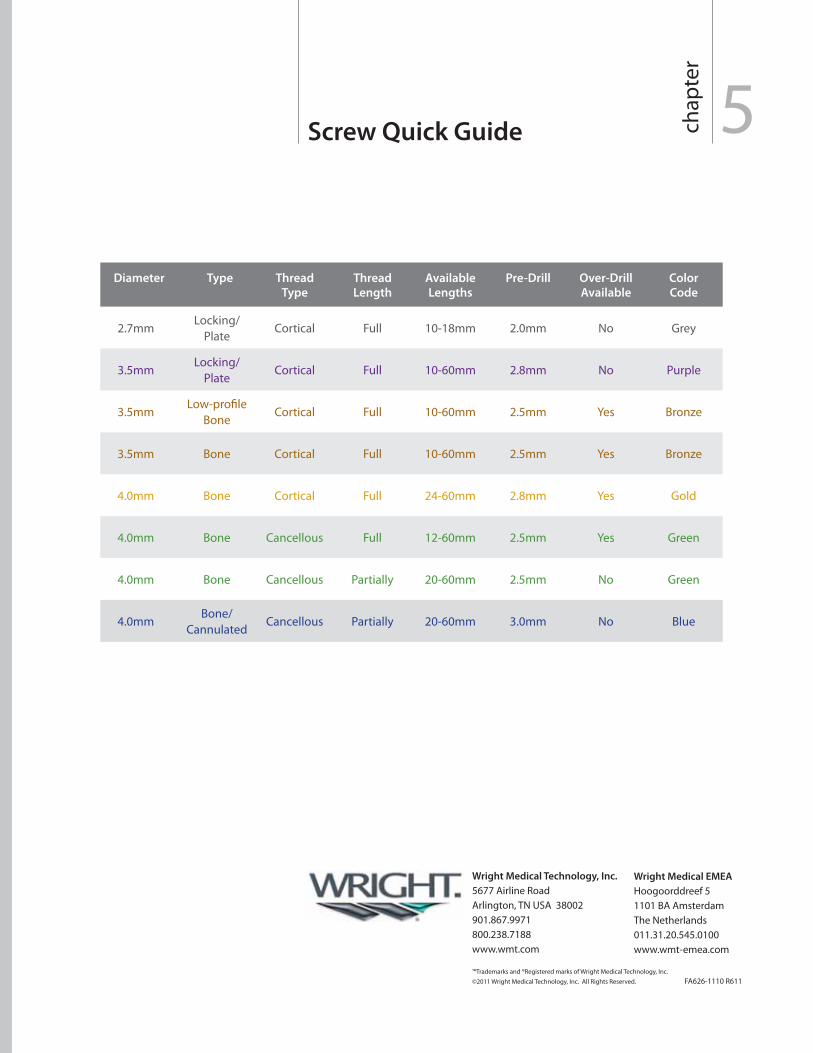
Diameter Type Thread
Type
Thread
Length
Available
Lengths
Pre-Drill Over-Drill
Available
Color
Code
2.7mmLocking/
PlateCortical Full 10-18mm 2.0mm No Grey
3.5mmLocking/
PlateCortical Full 10-60mm 2.8mm No Purple
3.5mmLow-profile
BoneCortical Full 10-60mm 2.5mm Yes Bronze
3.5mm Bone Cortical Full 10-60mm 2.5mm Yes Bronze
4.0mm Bone Cortical Full 24-60mm 2.8mm Yes Gold
4.0mm Bone Cancellous Full 12-60mm 2.5mm Yes Green
4.0mm Bone Cancellous Partially 20-60mm 2.5mm No Green
4.0mmBone/
CannulatedCancellous Partially 20-60mm 3.0mm No Blue
Screw Quick Guide 5chap
ter