Embed Size (px)
Citation preview
Surgical Technique
Over 1 million times per year, Biomet helps one surgeon provide personalized care to one patient.
The science and art of medical care is to provide the right
solution for each individual patient. This requires clinical
mastery, a human connection between the surgeon and the
patient, and the right tools for each situation.
At Biomet, we strive to view our work through the eyes of one
surgeon and one patient. We treat every solution we provide
as if it’s meant for a family member.
Our approach to innovation creates real solutions that assist
each surgeon in the delivery of durable personalized care
to each patient, whether that solution requires a minimally-
invasive surgical technique, advanced biomaterials, or a
patient-matched implant.
When one surgeon connects with one patient to provide personalized care, the promise of medicine is fulfilled.
One Surgeon. One Patient.
Surgical Technique Summary ....................................................................................................................................................................................2
Overview ...............................................................................................................................................................................................................................4
Preoperative Planning ...................................................................................................................................................................................................6
Incision ..................................................................................................................................................................................................................................6
Patella Preparation .........................................................................................................................................................................................................7
Patella Resection 7
Femoral Preparation.....................................................................................................................................................................................................10
Distal Femoral Resection 10
Femoral Sizing 13
4-in-1 Femoral Cuts 14
Tibial Preparation ..........................................................................................................................................................................................................15
Tibial Resection with Intact/Functional ACL 15
Tibial Resection without Intact/Functional ACL 26
Stem Preparation without the ACL 27
Trial Reduction.................................................................................................................................................................................................................28
Implant Reduction ........................................................................................................................................................................................................ 30
Tibial Tray Implantation with Intact/Functioning ACL 30
Tibial Tray Implantation without Intact/Functioning ACL 32
Femoral Component Implantation 33
Patellar Component Implantation 34
Tibial Bearings and Locking Bar Implantations 34
V A N G U A R D X P Total Knee SystemTable of Contents
Biomet does not practice medicine. The treating surgeon is responsible for determining the appropriate treatment, technique(s), and product(s) for each individual patient. This technique was prepared in conjunction with the Vanguard XP Total Knee developing surgeons; and the “eXPert Advice” sections provided in this surgical technique represent the Vanguard XP developing surgeons’ recommended approach.
This material is intended for health care professionals and the Biomet sales force. Distribution to any other recipient is prohibited. All content herein is protected by copyright, trademarks and other intellectual property rights owned by or licensed to Biomet Inc. or its affiliates unless otherwise indicated, and must not be redistributed, duplicated or disclosed, in whole or in part, without the express written consent of Biomet.
1
4
7
2
5
8
3
6
9
2
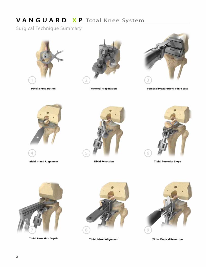
V A N G U A R D X P Total Knee SystemSurgical Technique Summary
Femoral Preparation: 4-in-1 cuts
Initial Island Alignment
Tibial Resection Depth Tibial Island Alignment
Tibial Posterior SlopeTibial Resection
Tibial Vertical Resection
Patella Preparation Femoral Preparation
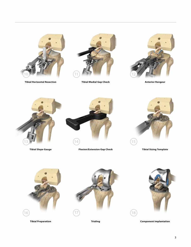
10
13
16
11
14
17
12
15
18
3
Anterior Rongeur
Tibial Slope Gauge Flexion/Extension Gap Check Tibial Sizing Template
Tibial Preparation Trialing Component Implantation
Tibial Horizontal Resection Tibial Medial Gap Check
Overview
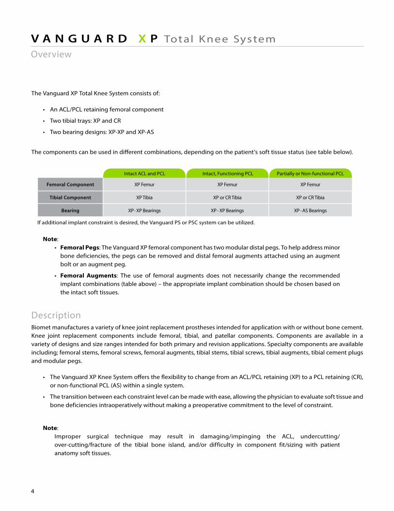
Intact ACL and PCL Intact, Functioning PCL Partially or Non-functional PCL
Femoral Component XP Femur XP Femur XP Femur
Tibial Component XP Tibia XP or CR Tibia XP or CR Tibia
Bearing XP- XP Bearings XP- XP Bearings XP- AS Bearings
If additional implant constraint is desired, the Vanguard PS or PSC system can be utilized.
4
V A N G U A R D X P Total Knee System
The Vanguard XP Total Knee System consists of:
• An ACL/PCL retaining femoral component
• Two tibial trays: XP and CR
• Two bearing designs: XP-XP and XP-AS
The components can be used in different combinations, depending on the patient’s soft tissue status (see table below).
Note: • Femoral Pegs: The Vanguard XP femoral component has two modular distal pegs. To help address minor bone deficiencies, the pegs can be removed and distal femoral augments attached using an augment bolt or an augment peg.
• Femoral Augments: The use of femoral augments does not necessarily change the recommended implant combinations (table above) – the appropriate implant combination should be chosen based on the intact soft tissues.
DescriptionBiomet manufactures a variety of knee joint replacement prostheses intended for application with or without bone cement. Knee joint replacement components include femoral, tibial, and patellar components. Components are available in a variety of designs and size ranges intended for both primary and revision applications. Specialty components are available including; femoral stems, femoral screws, femoral augments, tibial stems, tibial screws, tibial augments, tibial cement plugs and modular pegs.
• The Vanguard XP Knee System offers the flexibility to change from an ACL/PCL retaining (XP) to a PCL retaining (CR), or non-functional PCL (AS) within a single system.
• The transition between each constraint level can be made with ease, allowing the physician to evaluate soft tissue and bone deficiencies intraoperatively without making a preoperative commitment to the level of constraint.
Note: Improper surgical technique may result in damaging/impinging the ACL, undercutting/ over-cutting/fracture of the tibial bone island, and/or difficulty in component fit/sizing with patient anatomy soft tissues.
The Vanguard XP Total Knee System, supporting instrumentation platform, and surgical technique have been designed in collaboration with the Vanguard XP Development Team:
Prof. Tom AndriacchiDr. Keith BerendDr. Jeff DeClaireDr. Craig Della ValleDr. Jorge GalanteDr. Adolph LombardiDr. Chris Peters
5
INDICATIONS
1. Painful and disabled knee joint resulting from osteoarthritis, rheumatoid arthritis or traumatic arthritis where one or more compartments are involved.
2. Correction of varus, valgus, or post-traumatic deformity.
3. Correction or revision of unsuccessful osteotomy, arthrodesis, or failure of previous joint replacement procedure.
Femoral components and tibial tray components with porous coatings are indicated for cemented and uncemented biological fixation application. Non-coated (Interlok) femoral components, tibial tray components and all polyethylene patellar components are indicated for cemented application only. Regenerex components (where available) are intended only for uncemented fixation application.
CONTRAINDICATIONS
Absolute contraindications include: infection, sepsis, and osteomyelitis. Relative contraindications include:
1) an uncooperative patient or a patient with neurologic disorders who is incapable of following directions, 2) osteoporosis, 3) metabolic disorders which may impair bone formation, 4) osteomalacia, 5) distant foci of infections which may spread to the implant site, 6) rapid joint destruction, marked bone loss or bone resorption apparent on roent genogram, 7) vascular insufficiency, muscular atrophy, neuromuscular disease, and/or 8) incomplete or deficient soft tissue surrounding the knee.
For complete product information, including warnings, precautions, and potential adverse effects, see the package insert and www.Biomet.com where available. Check for country product clearances and reference product specific instructions for use.
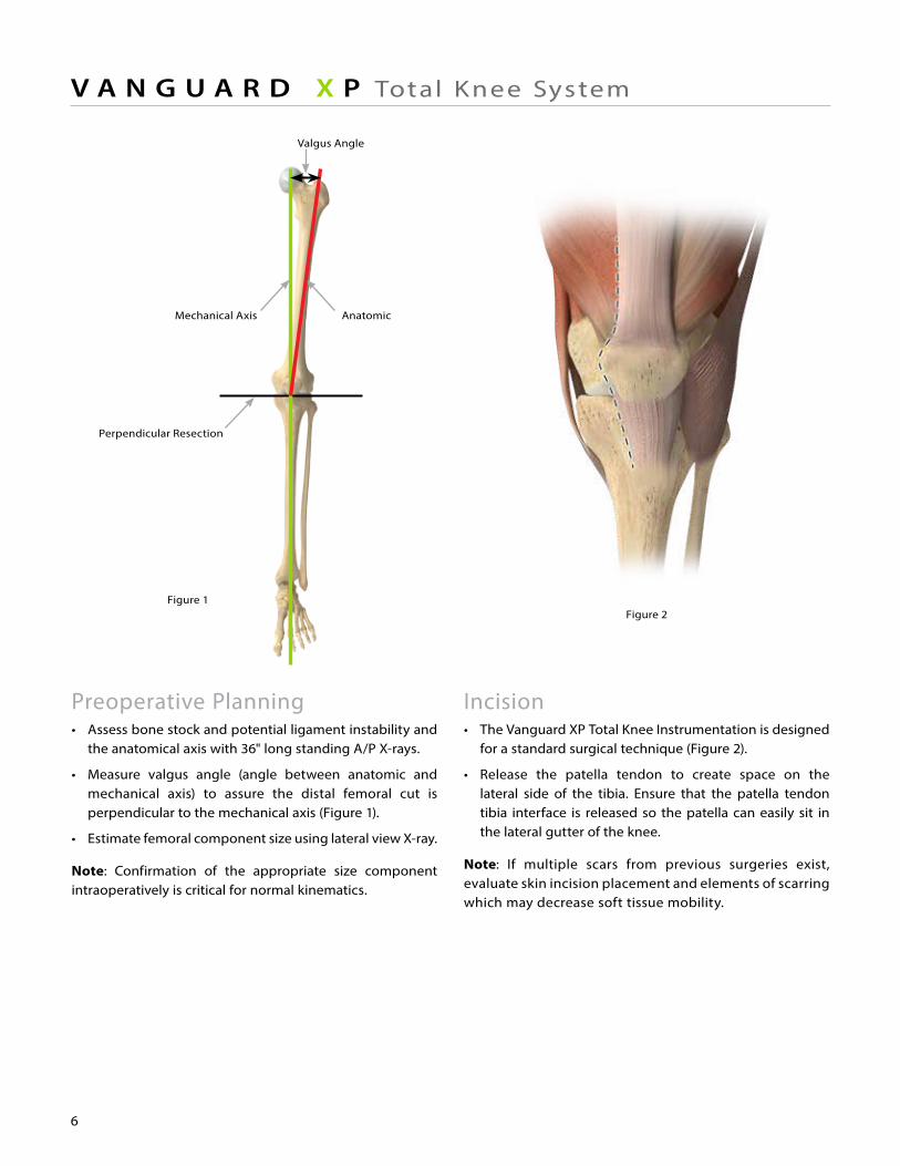
Figure 1Figure 2
Perpendicular Resection
Mechanical Axis Anatomic
Valgus Angle
6
V A N G U A R D X P Total Knee System
Preoperative Planning• Assess bone stock and potential ligament instability and the anatomical axis with 36" long standing A/P X-rays.
• Measure valgus angle (angle between anatomic and mechanical axis) to assure the distal femoral cut is perpendicular to the mechanical axis (Figure 1).
• Estimate femoral component size using lateral view X-ray.
Note: Confirmation of the appropriate size component intraoperatively is critical for normal kinematics.
Incision• The Vanguard XP Total Knee Instrumentation is designed for a standard surgical technique (Figure 2).
• Release the patella tendon to create space on the lateral side of the tibia. Ensure that the patella tendon tibia interface is released so the patella can easily sit in the lateral gutter of the knee.
Note: If multiple scars from previous surgeries exist, evaluate skin incision placement and elements of scarring which may decrease soft tissue mobility.
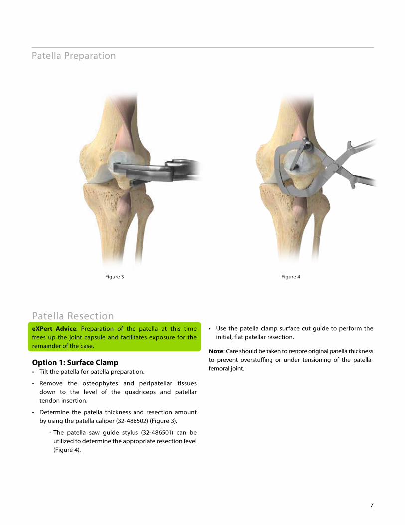
Figure 3 Figure 4
7
Patella Preparation
Patella ResectioneXPert Advice: Preparation of the patella at this time frees up the joint capsule and facilitates exposure for the remainder of the case.
Option 1: Surface Clamp• Tilt the patella for patella preparation.
• Remove the osteophytes and peripatellar tissues down to the level of the quadriceps and patellar tendon insertion.
• Determine the patella thickness and resection amount by using the patella caliper (32-486502) (Figure 3).
- The patella saw guide stylus (32-486501) can be utilized to determine the appropriate resection level (Figure 4).
• Use the patella clamp surface cut guide to perform the initial, flat patellar resection.
Note: Care should be taken to restore original patella thickness to prevent overstuffing or under tensioning of the patella-femoral joint.
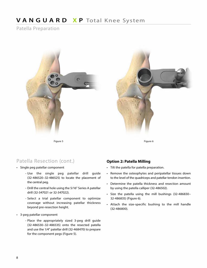
Figure 6Figure 5
8
V A N G U A R D X P Total Knee SystemPatella Preparation
Patella Resection (cont.)• Single peg patellar component
- Use the single peg patellar drill guide (32-486520–32-486525) to locate the placement of the central peg.
- Drill the central hole using the 5/16" Series A patellar drill (32-347021 or 32-347022).
- Select a trial patellar component to optimize coverage without increasing patellar thickness beyond pre-resection height.
• 3-peg patellar component
- Place the appropriately sized 3-peg drill guide (32-486530–32-486535) onto the resected patella and use the 1/4" patellar drill (32-468470) to prepare for the component pegs (Figure 5).
Option 2: Patella Milling• Tilt the patella for patella preparation.
• Remove the osteophytes and peripatellar tissues down to the level of the quadriceps and patellar tendon insertion.
• Determine the patella thickness and resection amount by using the patella calliper (32-486502).
• Size the patella using the mill bushings (32-486830– 32-486835) (Figure 6).
• Attach the size-specific bushing to the mill handle (32-486800).
Patella Preparation
Figure 7
9
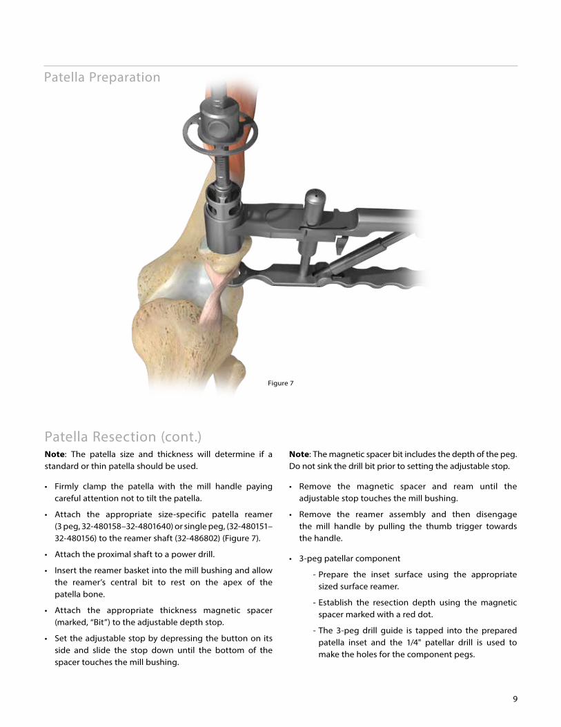
Patella Resection (cont.)Note: The patella size and thickness will determine if a standard or thin patella should be used.
• Firmly clamp the patella with the mill handle paying careful attention not to tilt the patella.
• Attach the appropriate size-specific patella reamer (3 peg, 32-480158–32-4801640) or single peg, (32-480151– 32-480156) to the reamer shaft (32-486802) (Figure 7).
• Attach the proximal shaft to a power drill.
• Insert the reamer basket into the mill bushing and allow the reamer’s central bit to rest on the apex of the patella bone.
• Attach the appropriate thickness magnetic spacer (marked, “Bit”) to the adjustable depth stop.
• Set the adjustable stop by depressing the button on its side and slide the stop down until the bottom of the spacer touches the mill bushing.
Note: The magnetic spacer bit includes the depth of the peg. Do not sink the drill bit prior to setting the adjustable stop.
• Remove the magnetic spacer and ream until the adjustable stop touches the mill bushing.
• Remove the reamer assembly and then disengage the mill handle by pulling the thumb trigger towards the handle.
• 3-peg patellar component
- Prepare the inset surface using the appropriate sized surface reamer.
- Establish the resection depth using the magnetic spacer marked with a red dot.
- The 3-peg drill guide is tapped into the prepared patella inset and the 1/4" patellar drill is used to make the holes for the component pegs.
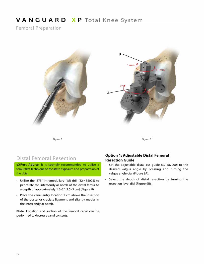
Figure 8 Figure 9
B
A
10
V A N G U A R D X P Total Knee System
Distal Femoral Resection eXPert Advice: It is strongly recommended to utilize a femur first technique to facilitate exposure and preparation of the tibia.
• Utilize the .375" intramedullary (IM) drill (32-485025) to penetrate the intercondylar notch of the distal femur to a depth of approximately 1.5–2" (3.5–5 cm) (Figure 8).
• Place the canal entry location 1 cm above the insertion of the posterior cruciate ligament and slightly medial in the intercondylar notch.
Note: Irrigation and suction of the femoral canal can be performed to decrease canal contents.
Option 1: Adjustable Distal Femoral Resection Guide• Set the adjustable distal cut guide (32-487000) to the desired valgus angle by pressing and turning the valgus angle dial (Figure 9A).
• Select the depth of distal resection by turning the resection level dial (Figure 9B).
Femoral Preparation
1 mm
90
00
11 mm
90
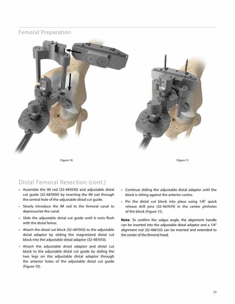
Figure 10 Figure 11
11
Femoral Preparation
Distal Femoral Resection (cont.)• Assemble the IM rod (32-485030) and adjustable distal cut guide (32-487000) by inserting the IM rod through the central hole of the adjustable distal cut guide.
• Slowly introduce the IM rod to the femoral canal to depressurize the canal.
• Slide the adjustable distal cut guide until it rests flush with the distal femur.
• Attach the distal cut block (32-487002) to the adjustable distal adaptor by sliding the magnetized distal cut block into the adjustable distal adaptor (32-487010).
• Attach the adjustable distal adaptor and distal cut block to the adjustable distal cut guide by sliding the two legs on the adjustable distal adaptor through the anterior holes of the adjustable distal cut guide (Figure 10).
• Continue sliding the adjustable distal adaptor until the block is sitting against the anterior cortex.
• Pin the distal cut block into place using 1/8" quick release drill pins (32-467619) in the center pinholes of the block (Figure 11).
Note: To confirm the valgus angle, the alignment handle can be inserted into the adjustable distal adaptor and a 1/4" alignment rod (32-486135) can be inserted and extended to the center of the femoral head.
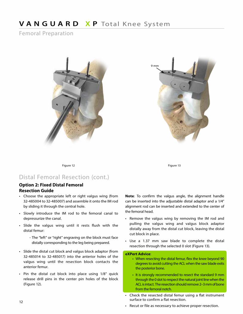
Figure 13 Figure 14Figure 12
12
V A N G U A R D X P Total Knee System
Note: To confirm the valgus angle, the alignment handle can be inserted into the adjustable distal adaptor and a 1/4" alignment rod can be inserted and extended to the center of the femoral head.
• Remove the valgus wing by removing the IM rod and pulling the valgus wing and valgus block adaptor distally away from the distal cut block, leaving the distal cut block in place.
• Use a 1.37 mm saw blade to complete the distal resection through the selected 0 slot (Figure 13).
eXPert Advice: • When resecting the distal femur, flex the knee beyond 90 degrees to avoid cutting the ACL when the saw blade exits the posterior bone.
• It is strongly recommended to resect the standard 9 mm through the 0 slot to respect the natural joint line when the ACL is intact. The resection should remove 2–3 mm of bone from the femoral notch.
• Check the resected distal femur using a flat instrument surface to confirm a flat resection.
• Recut or file as necessary to achieve proper resection.
Femoral Preparation
Distal Femoral Resection (cont.)Option 2: Fixed Distal Femoral Resection Guide• Choose the appropriate left or right valgus wing (from 32-485004 to 32-485007) and assemble it onto the IM rod by sliding it through the central hole.
• Slowly introduce the IM rod to the femoral canal to depressurize the canal.
• Slide the valgus wing until it rests flush with the distal femur:
- The “left” or “right” engraving on the block must face distally corresponding to the leg being prepared.
• Slide the distal cut block and valgus block adaptor (from 32-485014 to 32-485017) into the anterior holes of the valgus wing until the resection block contacts the anterior femur.
• Pin the distal cut block into place using 1/8" quick release drill pins in the center pin holes of the block (Figure 12).
9 mm
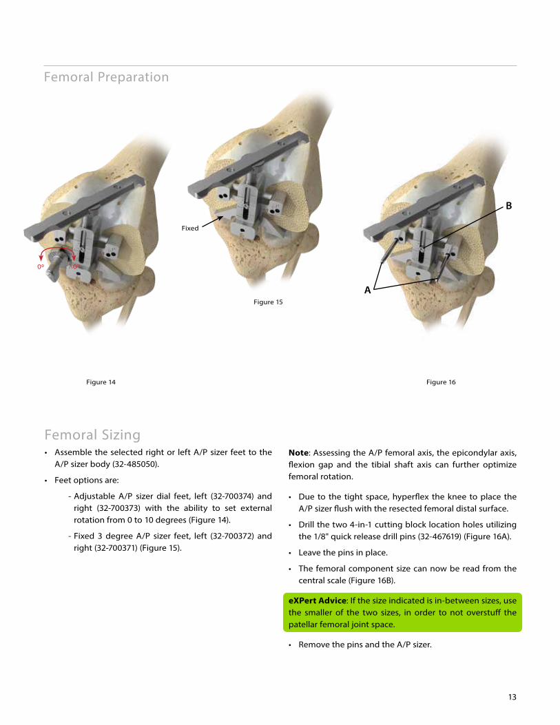
Figure 14 Figure 16
Figure 15
Fixed
B
A
13
Femoral Sizing• Assemble the selected right or left A/P sizer feet to the A/P sizer body (32-485050).
• Feet options are:
- Adjustable A/P sizer dial feet, left (32-700374) and right (32-700373) with the ability to set external rotation from 0 to 10 degrees (Figure 14).
- Fixed 3 degree A/P sizer feet, left (32-700372) and right (32-700371) (Figure 15).
Note: Assessing the A/P femoral axis, the epicondylar axis, flexion gap and the tibial shaft axis can further optimize femoral rotation.
• Due to the tight space, hyperflex the knee to place the A/P sizer flush with the resected femoral distal surface.
• Drill the two 4-in-1 cutting block location holes utilizing the 1/8" quick release drill pins (32-467619) (Figure 16A).
• Leave the pins in place.
• The femoral component size can now be read from the central scale (Figure 16B).
eXPert Advice: If the size indicated is in-between sizes, use the smaller of the two sizes, in order to not overstuff the patellar femoral joint space.
• Remove the pins and the A/P sizer.
Femoral Preparation
^0000
A
B
Figure 17 Figure 18
A
14
V A N G U A R D X P Total Knee System
eXPert Advice: A narrow (approximately 12–13 mm) saw blade should be used for the posterior and posterior chamfer resections to prevent saw blade contact with the ACL protector.
• When making the posterior bone and posterior chamfer resections, the narrow sawblade should not be angled behind the ACL protector and extra care should be taken to protect the ACL.
Note:• After making the anterior resection, inspection of the anterior resection relative to the anterior cortex can be assessed.
• If downsizing is possible, the initial block can be removed and the smaller sized block replaced. The anterior femur and chamfer then can be resected.
eXPert Advice: A femoral notchplasty should be performed to remove osteophytes, increasing visualization of the femoral notch to ensure the ACL has adequate clearance.
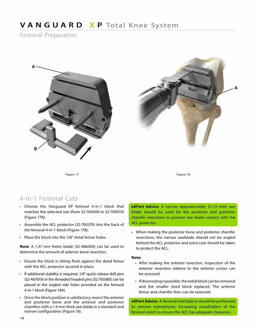
4-in-1 Femoral Cuts• Choose the Vanguard XP femoral 4-in-1 block that matches the selected size (from 32-700000 to 32-700010) (Figure 17A).
• Assemble the ACL protector (32-700370) into the back of the femoral 4-in-1 block (Figure 17B).
• Place the block into the 1/8" distal femur holes.
Note: A 1.37 mm feeler blade (32-486000) can be used to determine the amount of anterior bone resection.
• Ensure the block is sitting flush against the distal femur with the ACL protector secured in place.
• If additional stability is required, 1/8" quick release drill pins (32-467619) or the threaded headed pins (32-700380) can be placed in the angled side holes provided on the femoral 4-in-1 block (Figure 18A).
• Once the block position is satisfactory, resect the anterior and posterior bone and the anterior and posterior chamfers with a 1.4 mm thick saw blade in a standard and narrow configuration (Figure 18).
Femoral Preparation
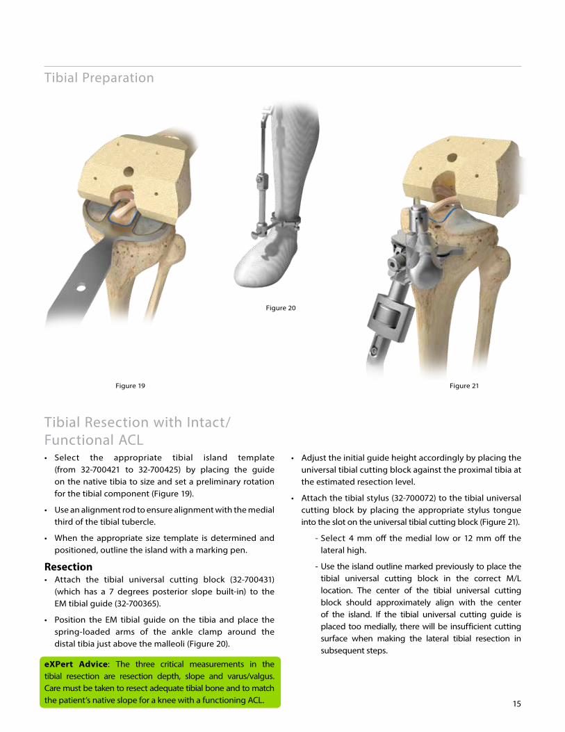
Figure 20
Figure 19 Figure 21
15
Tibial Preparation
Tibial Resection with Intact/Functional ACL • Select the appropriate tibial island template (from 32-700421 to 32-700425) by placing the guide on the native tibia to size and set a preliminary rotation for the tibial component (Figure 19).
• Use an alignment rod to ensure alignment with the medial third of the tibial tubercle.
• When the appropriate size template is determined and positioned, outline the island with a marking pen.
Resection• Attach the tibial universal cutting block (32-700431) (which has a 7 degrees posterior slope built-in) to the EM tibial guide (32-700365).
• Position the EM tibial guide on the tibia and place the spring-loaded arms of the ankle clamp around the distal tibia just above the malleoli (Figure 20).
eXPert Advice: The three critical measurements in the tibial resection are resection depth, slope and varus/valgus. Care must be taken to resect adequate tibial bone and to match the patient’s native slope for a knee with a functioning ACL.
• Adjust the initial guide height accordingly by placing the universal tibial cutting block against the proximal tibia at the estimated resection level.
• Attach the tibial stylus (32-700072) to the tibial universal cutting block by placing the appropriate stylus tongue into the slot on the universal tibial cutting block (Figure 21).
- Select 4 mm off the medial low or 12 mm off the lateral high.
- Use the island outline marked previously to place the tibial universal cutting block in the correct M/L location. The center of the tibial universal cutting block should approximately align with the center of the island. If the tibial universal cutting guide is placed too medially, there will be insufficient cutting surface when making the lateral tibial resection in subsequent steps.
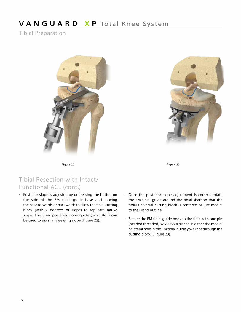
Figure 23Figure 22
• Once the posterior slope adjustment is correct, rotate the EM tibial guide around the tibial shaft so that the tibial universal cutting block is centered or just medial to the island outline.
• Secure the EM tibial guide body to the tibia with one pin (headed threaded, 32-700380) placed in either the medial or lateral hole in the EM tibial guide yoke (not through the cutting block) (Figure 23).
16
V A N G U A R D X P Total Knee SystemTibial Preparation
Tibial Resection with Intact/Functional ACL (cont.)• Posterior slope is adjusted by depressing the button on the side of the EM tibial guide base and moving the base forwards or backwards to allow the tibial cutting block (with 7 degrees of slope) to replicate native slope. The tibial posterior slope guide (32-700430) can be used to assist in assessing slope (Figure 22).
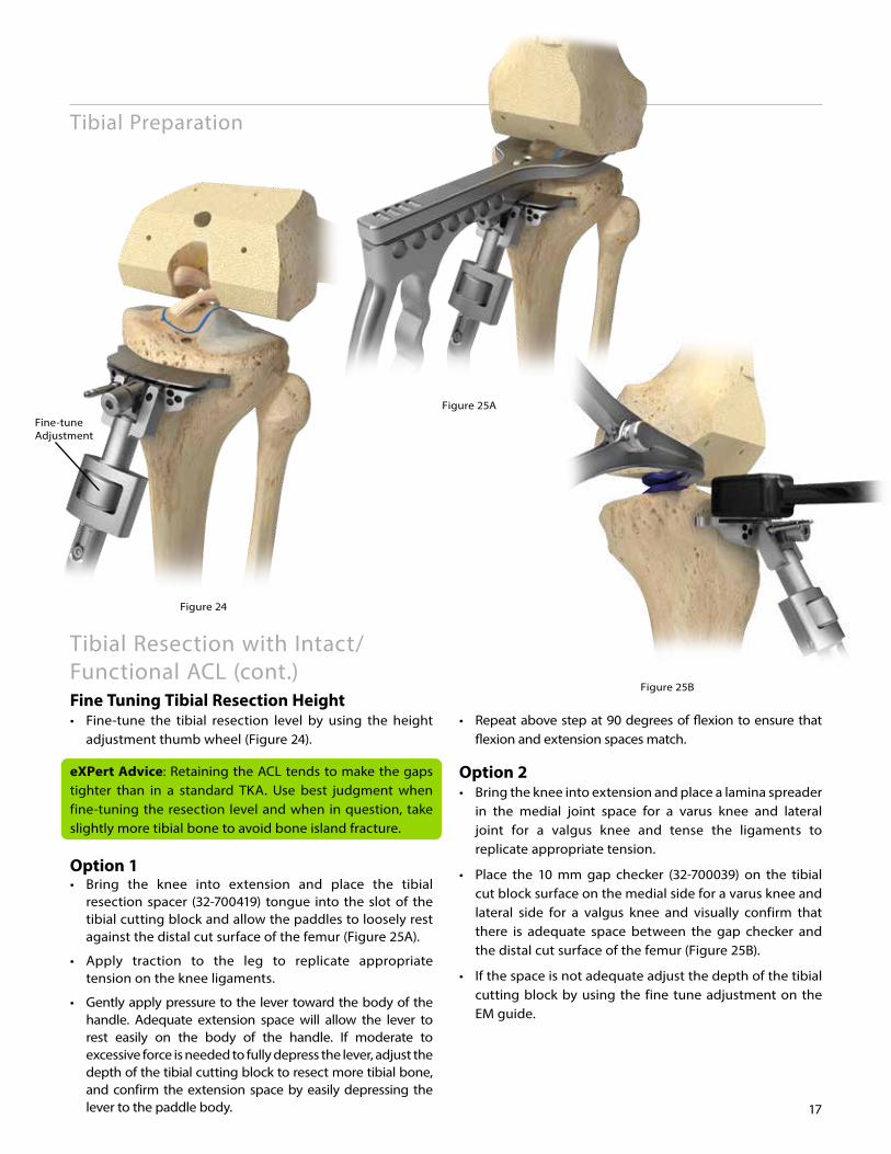
Figure 24
Fine-tune Adjustment
Figure 25A
Figure 25B
17
Tibial Preparation
Tibial Resection with Intact/Functional ACL (cont.)Fine Tuning Tibial Resection Height• Fine-tune the tibial resection level by using the height adjustment thumb wheel (Figure 24).
eXPert Advice: Retaining the ACL tends to make the gaps tighter than in a standard TKA. Use best judgment when fine-tuning the resection level and when in question, take slightly more tibial bone to avoid bone island fracture.
Option 1• Bring the knee into extension and place the tibial resection spacer (32-700419) tongue into the slot of the tibial cutting block and allow the paddles to loosely rest against the distal cut surface of the femur (Figure 25A).
• Apply traction to the leg to replicate appropriate tension on the knee ligaments.
• Gently apply pressure to the lever toward the body of the handle. Adequate extension space will allow the lever to rest easily on the body of the handle. If moderate to excessive force is needed to fully depress the lever, adjust the depth of the tibial cutting block to resect more tibial bone, and confirm the extension space by easily depressing the lever to the paddle body.
• Repeat above step at 90 degrees of flexion to ensure that flexion and extension spaces match.
Option 2• Bring the knee into extension and place a lamina spreader in the medial joint space for a varus knee and lateral joint for a valgus knee and tense the ligaments to replicate appropriate tension.
• Place the 10 mm gap checker (32-700039) on the tibial cut block surface on the medial side for a varus knee and lateral side for a valgus knee and visually confirm that there is adequate space between the gap checker and the distal cut surface of the femur (Figure 25B).
• If the space is not adequate adjust the depth of the tibial cutting block by using the fine tune adjustment on the EM guide.
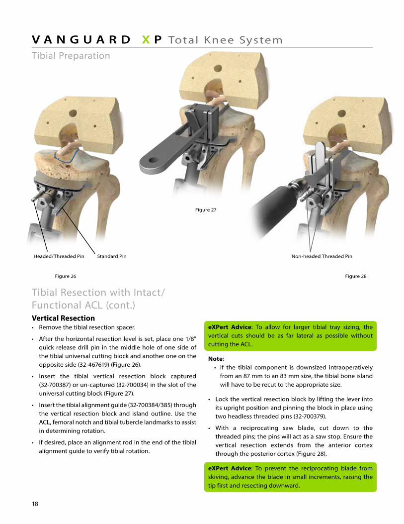
Figure 26
Standard Pin Non-headed Threaded PinHeaded/Threaded Pin
Figure 28
Figure 27
18
V A N G U A R D X P Total Knee SystemTibial Preparation
Tibial Resection with Intact/Functional ACL (cont.)Vertical Resection• Remove the tibial resection spacer.
• After the horizontal resection level is set, place one 1/8" quick release drill pin in the middle hole of one side of the tibial universal cutting block and another one on the opposite side (32-467619) (Figure 26).
• Insert the tibial vertical resection block captured (32-700387) or un-captured (32-700034) in the slot of the universal cutting block (Figure 27).
• Insert the tibial alignment guide (32-700384/385) through the vertical resection block and island outline. Use the ACL, femoral notch and tibial tubercle landmarks to assist in determining rotation.
• If desired, place an alignment rod in the end of the tibial alignment guide to verify tibial rotation.
eXPert Advice: To allow for larger tibial tray sizing, the vertical cuts should be as far lateral as possible without cutting the ACL.
Note:• If the tibial component is downsized intraoperatively from an 87 mm to an 83 mm size, the tibial bone island will have to be recut to the appropriate size.
• Lock the vertical resection block by lifting the lever into its upright position and pinning the block in place using two headless threaded pins (32-700379).
• With a reciprocating saw blade, cut down to the threaded pins; the pins will act as a saw stop. Ensure the vertical resection extends from the anterior cortex through the posterior cortex (Figure 28).
eXPert Advice: To prevent the reciprocating blade from skiving, advance the blade in small increments, raising the tip first and resecting downward.
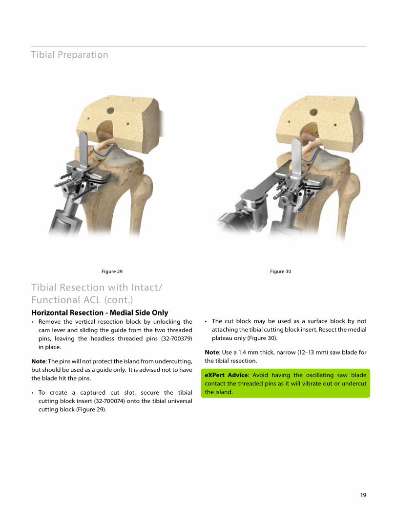
Figure 28 Figure 29 Figure 30
19
Tibial Preparation
Tibial Resection with Intact/Functional ACL (cont.)Horizontal Resection - Medial Side Only• Remove the vertical resection block by unlocking the cam lever and sliding the guide from the two threaded pins, leaving the headless threaded pins (32-700379) in place.
Note: The pins will not protect the island from undercutting, but should be used as a guide only. It is advised not to have the blade hit the pins.
• To create a captured cut slot, secure the tibial cutting block insert (32-700074) onto the tibial universal cutting block (Figure 29).
• The cut block may be used as a surface block by not attaching the tibial cutting block insert. Resect the medial plateau only (Figure 30).
Note: Use a 1.4 mm thick, narrow (12–13 mm) saw blade for the tibial resection.
eXPert Advice: Avoid having the oscillating saw blade contact the threaded pins as it will vibrate out or undercut the island.
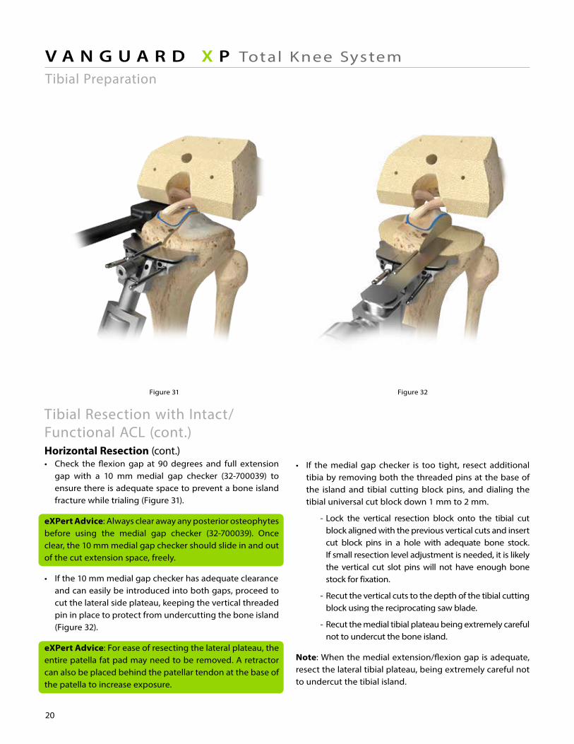
Figure 32Figure 31 Figure 33
20
V A N G U A R D X P Total Knee System
• If the medial gap checker is too tight, resect additional tibia by removing both the threaded pins at the base of the island and tibial cutting block pins, and dialing the tibial universal cut block down 1 mm to 2 mm.
- Lock the vertical resection block onto the tibial cut block aligned with the previous vertical cuts and insert cut block pins in a hole with adequate bone stock. If small resection level adjustment is needed, it is likely the vertical cut slot pins will not have enough bone stock for fixation.
- Recut the vertical cuts to the depth of the tibial cutting block using the reciprocating saw blade.
- Recut the medial tibial plateau being extremely careful not to undercut the bone island.
Note: When the medial extension/flexion gap is adequate, resect the lateral tibial plateau, being extremely careful not to undercut the tibial island.
Tibial Preparation
Tibial Resection with Intact/Functional ACL (cont.)Horizontal Resection (cont.)• Check the flexion gap at 90 degrees and full extension gap with a 10 mm medial gap checker (32-700039) to ensure there is adequate space to prevent a bone island fracture while trialing (Figure 31).
eXPert Advice: Always clear away any posterior osteophytes before using the medial gap checker (32-700039). Once clear, the 10 mm medial gap checker should slide in and out of the cut extension space, freely.
• If the 10 mm medial gap checker has adequate clearance and can easily be introduced into both gaps, proceed to cut the lateral side plateau, keeping the vertical threaded pin in place to protect from undercutting the bone island (Figure 32).
eXPert Advice: For ease of resecting the lateral plateau, the entire patella fat pad may need to be removed. A retractor can also be placed behind the patellar tendon at the base of the patella to increase exposure.
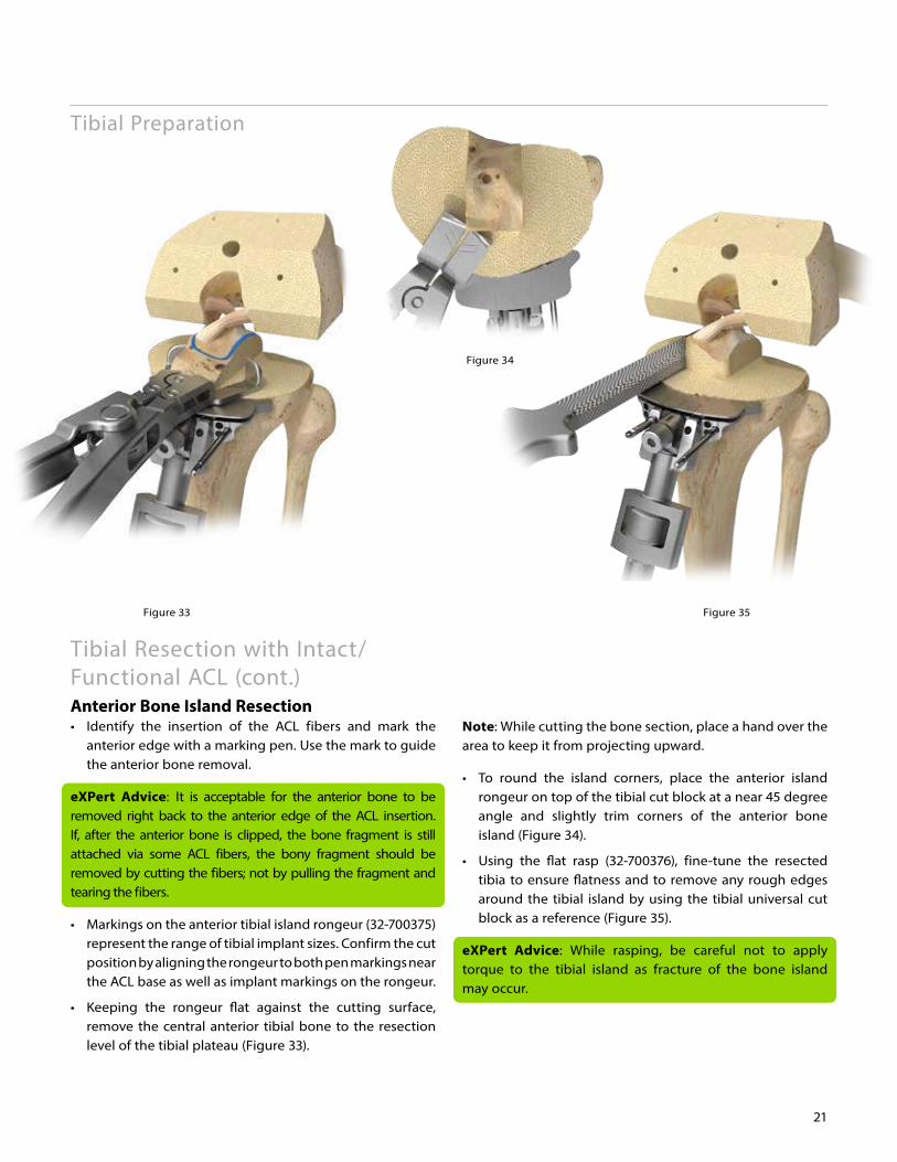
Figure 33 Figure 35
Figure 34
21
Tibial Resection with Intact/Functional ACL (cont.) Anterior Bone Island Resection • Identify the insertion of the ACL fibers and mark the anterior edge with a marking pen. Use the mark to guide the anterior bone removal.
eXPert Advice: It is acceptable for the anterior bone to be removed right back to the anterior edge of the ACL insertion. If, after the anterior bone is clipped, the bone fragment is still attached via some ACL fibers, the bony fragment should be removed by cutting the fibers; not by pulling the fragment and tearing the fibers.
• Markings on the anterior tibial island rongeur (32-700375) represent the range of tibial implant sizes. Confirm the cut position by aligning the rongeur to both pen markings near the ACL base as well as implant markings on the rongeur.
• Keeping the rongeur flat against the cutting surface, remove the central anterior tibial bone to the resection level of the tibial plateau (Figure 33).
Note: While cutting the bone section, place a hand over the area to keep it from projecting upward.
• To round the island corners, place the anterior island rongeur on top of the tibial cut block at a near 45 degree angle and slightly trim corners of the anterior bone island (Figure 34).
• Using the flat rasp (32-700376), fine-tune the resected tibia to ensure flatness and to remove any rough edges around the tibial island by using the tibial universal cut block as a reference (Figure 35).
eXPert Advice: While rasping, be careful not to apply torque to the tibial island as fracture of the bone island may occur.
Tibial Preparation
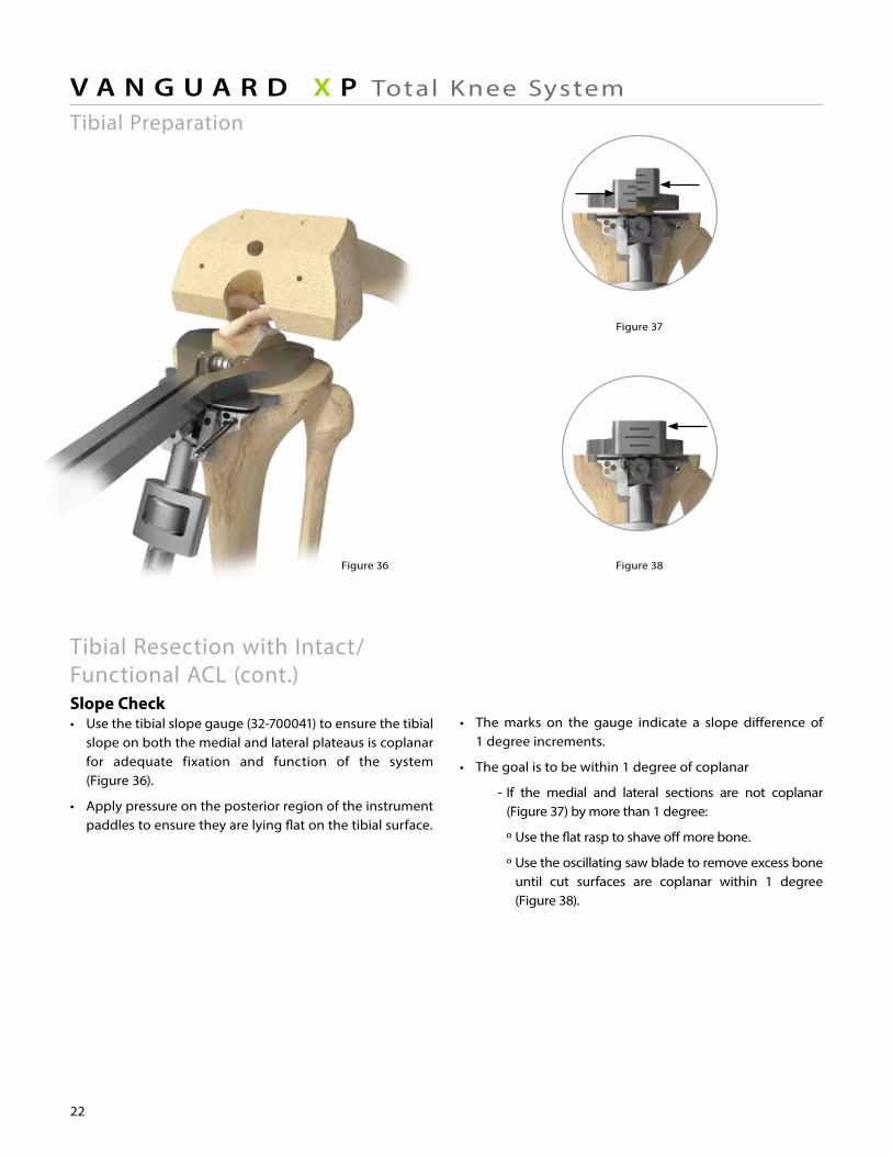
Figure 38
Figure 37
Figure 36
22
V A N G U A R D X P Total Knee System
• The marks on the gauge indicate a slope difference of 1 degree increments.
• The goal is to be within 1 degree of coplanar
- If the medial and lateral sections are not coplanar (Figure 37) by more than 1 degree:
º Use the flat rasp to shave off more bone.
º Use the oscillating saw blade to remove excess bone until cut surfaces are coplanar within 1 degree (Figure 38).
Tibial Preparation
Tibial Resection with Intact/Functional ACL (cont.)Slope Check• Use the tibial slope gauge (32-700041) to ensure the tibial slope on both the medial and lateral plateaus is coplanar for adequate fixation and function of the system (Figure 36).
• Apply pressure on the posterior region of the instrument paddles to ensure they are lying flat on the tibial surface.
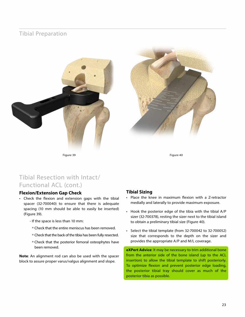
Figure 39 Figure 40
23
Tibial Resection with Intact/Functional ACL (cont.)Flexion/Extension Gap Check• Check the flexion and extension gaps with the tibial spacer (32-700040) to ensure that there is adequate spacing (10 mm should be able to easily be inserted) (Figure 39).
- If the space is less than 10 mm:
º Check that the entire meniscus has been removed.
º Check that the back of the tibia has been fully resected.
º Check that the posterior femoral osteophytes have been removed.
Note: An alignment rod can also be used with the spacer block to assure proper varus/valgus alignment and slope.
Tibial Preparation
Tibial Sizing• Place the knee in maximum flexion with a Z-retractor medially and laterally to provide maximum exposure.
• Hook the posterior edge of the tibia with the tibial A/P sizer (32-700378), resting the sizer next to the tibial island to obtain a preliminary tibial size (Figure 40).
• Select the tibial template (from 32-700042 to 32-700052) size that corresponds to the depth on the sizer and provides the appropriate A/P and M/L coverage.
eXPert Advice: It may be necessary to trim additional bone from the anterior side of the bone island (up to the ACL insertion) to allow the tibial template to shift posteriorly. To optimize flexion and prevent posterior edge loading, the posterior tibial tray should cover as much of the posterior tibia as possible.
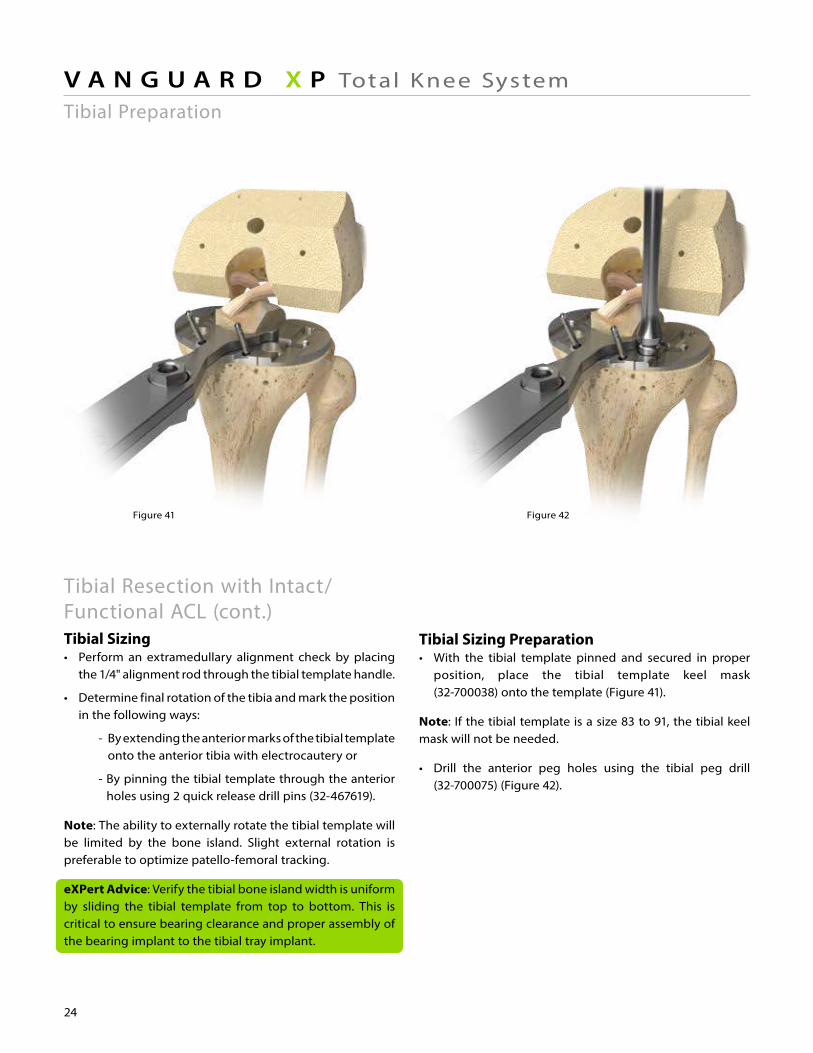
Figure 41 Figure 42 Figure 43
Tibial Resection with Intact/Functional ACL (cont.) Tibial Sizing• Perform an extramedullary alignment check by placing the 1/4" alignment rod through the tibial template handle.
• Determine final rotation of the tibia and mark the position in the following ways:
- By extending the anterior marks of the tibial template onto the anterior tibia with electrocautery or
- By pinning the tibial template through the anterior holes using 2 quick release drill pins (32-467619).
Note: The ability to externally rotate the tibial template will be limited by the bone island. Slight external rotation is preferable to optimize patello-femoral tracking.
eXPert Advice: Verify the tibial bone island width is uniform by sliding the tibial template from top to bottom. This is critical to ensure bearing clearance and proper assembly of the bearing implant to the tibial tray implant.
24
V A N G U A R D X P Total Knee SystemTibial Preparation
Tibial Sizing Preparation• With the tibial template pinned and secured in proper position, place the tibial template keel mask (32-700038) onto the template (Figure 41).
Note: If the tibial template is a size 83 to 91, the tibial keel mask will not be needed.
• Drill the anterior peg holes using the tibial peg drill (32-700075) (Figure 42).
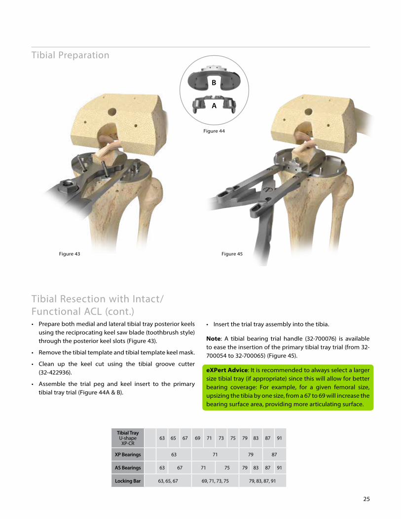
Figure 43
Figure 44
B
A
Figure 45
25
Tibial Resection with Intact/Functional ACL (cont.) • Prepare both medial and lateral tibial tray posterior keels using the reciprocating keel saw blade (toothbrush style) through the posterior keel slots (Figure 43).
• Remove the tibial template and tibial template keel mask.
• Clean up the keel cut using the tibial groove cutter (32-422936).
• Assemble the trial peg and keel insert to the primary tibial tray trial (Figure 44A & B).
Tibial Preparation
• Insert the trial tray assembly into the tibia.
Note: A tibial bearing trial handle (32-700076) is available to ease the insertion of the primary tibial tray trial (from 32-700054 to 32-700065) (Figure 45).
eXPert Advice: It is recommended to always select a larger size tibial tray (if appropriate) since this will allow for better bearing coverage: For example, for a given femoral size, upsizing the tibia by one size, from a 67 to 69 will increase the bearing surface area, providing more articulating surface.
Tibial TrayU-shape
XP-CR63 65 67 69 71 73 75 79 83 87 91
XP Bearings 63 71 79 87
AS Bearings 63 67 71 75 79 83 87 91
Locking Bar 63, 65, 67 69, 71, 73, 75 79, 83, 87, 91
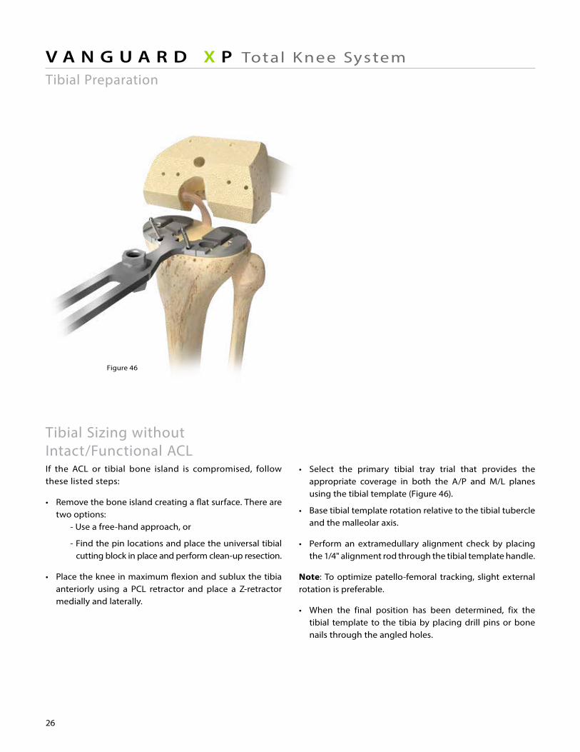
Figure 46
26
V A N G U A R D X P Total Knee System
Tibial Sizing without Intact/Functional ACL If the ACL or tibial bone island is compromised, follow these listed steps:
• Remove the bone island creating a flat surface. There are two options: - Use a free-hand approach, or
- Find the pin locations and place the universal tibial cutting block in place and perform clean-up resection.
• Place the knee in maximum flexion and sublux the tibia anteriorly using a PCL retractor and place a Z-retractor medially and laterally.
• Select the primary tibial tray trial that provides the appropriate coverage in both the A/P and M/L planes using the tibial template (Figure 46).
• Base tibial template rotation relative to the tibial tubercle and the malleolar axis.
• Perform an extramedullary alignment check by placing the 1/4" alignment rod through the tibial template handle.
Note: To optimize patello-femoral tracking, slight external rotation is preferable.
• When the final position has been determined, fix the tibial template to the tibia by placing drill pins or bone nails through the angled holes.
Tibial Preparation
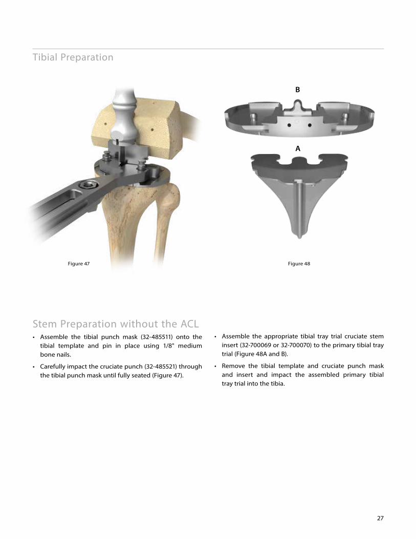
Figure 48Figure 47
B
A
27
Stem Preparation without the ACL• Assemble the tibial punch mask (32-485511) onto the tibial template and pin in place using 1/8" medium bone nails.
• Carefully impact the cruciate punch (32-485521) through the tibial punch mask until fully seated (Figure 47).
• Assemble the appropriate tibial tray trial cruciate stem insert (32-700069 or 32-700070) to the primary tibial tray trial (Figure 48A and B).
• Remove the tibial template and cruciate punch mask and insert and impact the assembled primary tibial tray trial into the tibia.
Tibial Preparation
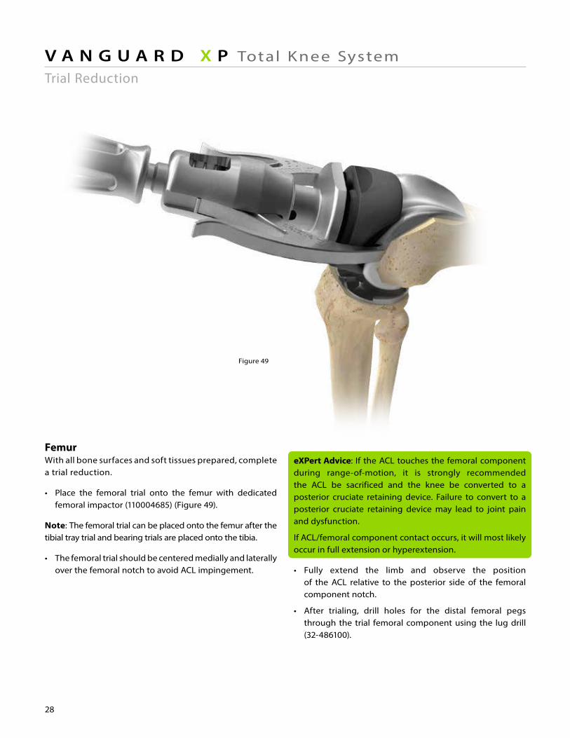
Figure 49 Figure 50
28
V A N G U A R D X P Total Knee System
FemurWith all bone surfaces and soft tissues prepared, complete a trial reduction.
• Place the femoral trial onto the femur with dedicated femoral impactor (110004685) (Figure 49).
Note: The femoral trial can be placed onto the femur after the tibial tray trial and bearing trials are placed onto the tibia.
• The femoral trial should be centered medially and laterally over the femoral notch to avoid ACL impingement.
eXPert Advice: If the ACL touches the femoral component during range-of-motion, it is strongly recommended the ACL be sacrificed and the knee be converted to a posterior cruciate retaining device. Failure to convert to a posterior cruciate retaining device may lead to joint pain and dysfunction.
If ACL/femoral component contact occurs, it will most likely occur in full extension or hyperextension.
• Fully extend the limb and observe the position of the ACL relative to the posterior side of the femoral component notch.
• After trialing, drill holes for the distal femoral pegs through the trial femoral component using the lug drill (32-486100).
Trial Reduction
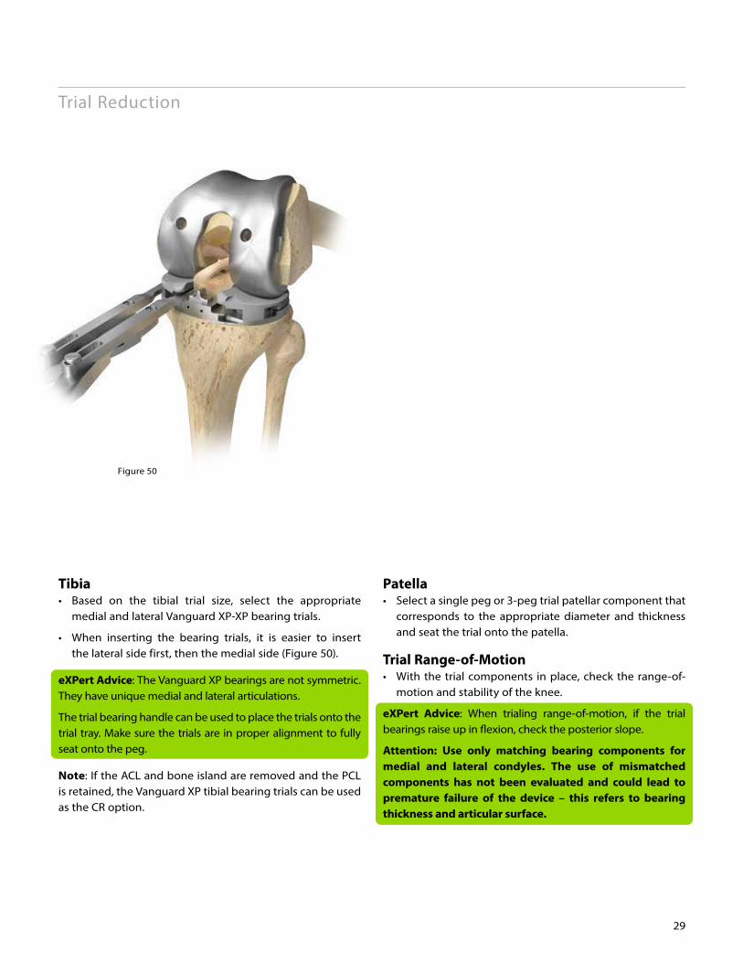
Figure 50
29
Trial Reduction
Tibia• Based on the tibial trial size, select the appropriate medial and lateral Vanguard XP-XP bearing trials.
• When inserting the bearing trials, it is easier to insert the lateral side first, then the medial side (Figure 50).
eXPert Advice: The Vanguard XP bearings are not symmetric. They have unique medial and lateral articulations.
The trial bearing handle can be used to place the trials onto the trial tray. Make sure the trials are in proper alignment to fully seat onto the peg.
Note: If the ACL and bone island are removed and the PCL is retained, the Vanguard XP tibial bearing trials can be used as the CR option.
Patella• Select a single peg or 3-peg trial patellar component that corresponds to the appropriate diameter and thickness and seat the trial onto the patella.
Trial Range-of-Motion• With the trial components in place, check the range-of- motion and stability of the knee.
eXPert Advice: When trialing range-of-motion, if the trial bearings raise up in flexion, check the posterior slope.
Attention: Use only matching bearing components for medial and lateral condyles. The use of mismatched components has not been evaluated and could lead to premature failure of the device – this refers to bearing thickness and articular surface.
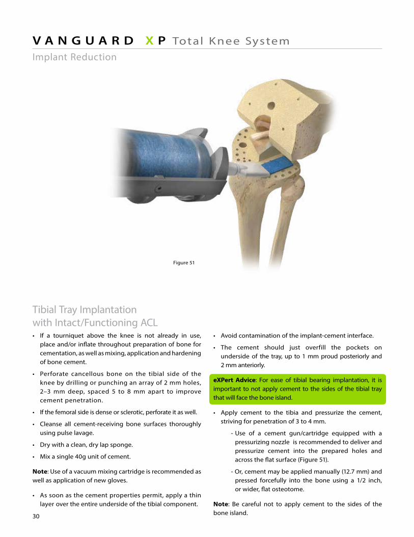
Figure 51
30
V A N G U A R D X P Total Knee System
• Avoid contamination of the implant-cement interface.
• The cement should just overfill the pockets on underside of the tray, up to 1 mm proud posteriorly and 2 mm anteriorly.
eXPert Advice: For ease of tibial bearing implantation, it is important to not apply cement to the sides of the tibial tray that will face the bone island.
• Apply cement to the tibia and pressurize the cement, striving for penetration of 3 to 4 mm.
- Use of a cement gun/cartridge equipped with a pressurizing nozzle is recommended to deliver and pressurize cement into the prepared holes and across the flat surface (Figure 51).
- Or, cement may be applied manually (12.7 mm) and pressed forcefully into the bone using a 1/2 inch, or wider, flat osteotome.
Note: Be careful not to apply cement to the sides of the bone island.
Tibial Tray Implantation with Intact/Functioning ACL• If a tourniquet above the knee is not already in use, place and/or inflate throughout preparation of bone for cementation, as well as mixing, application and hardening of bone cement.
• Perforate cancellous bone on the tibial side of the knee by drilling or punching an array of 2 mm holes, 2–3 mm deep, spaced 5 to 8 mm apart to improve cement penetration.
• If the femoral side is dense or sclerotic, perforate it as well.
• Cleanse all cement-receiving bone surfaces thoroughly using pulse lavage.
• Dry with a clean, dry lap sponge.
• Mix a single 40g unit of cement.
Note: Use of a vacuum mixing cartridge is recommended as well as application of new gloves.
• As soon as the cement properties permit, apply a thin layer over the entire underside of the tibial component.
Implant Reduction
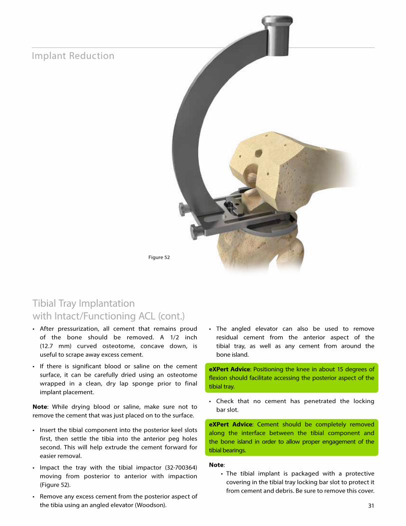
Figure 52
Implant Reduction
31
• The angled elevator can also be used to remove residual cement from the anterior aspect of the tibial tray, as well as any cement from around the bone island.
eXPert Advice: Positioning the knee in about 15 degrees of flexion should facilitate accessing the posterior aspect of the tibial tray.
• Check that no cement has penetrated the locking bar slot.
eXPert Advice: Cement should be completely removed along the interface between the tibial component and the bone island in order to allow proper engagement of the tibial bearings.
Note: • The tibial implant is packaged with a protective covering in the tibial tray locking bar slot to protect it from cement and debris. Be sure to remove this cover.
Tibial Tray Implantation with Intact/Functioning ACL (cont.)• After pressurization, all cement that remains proud of the bone should be removed. A 1/2 inch (12.7 mm) curved osteotome, concave down, is useful to scrape away excess cement.
• If there is significant blood or saline on the cement surface, it can be carefully dried using an osteotome wrapped in a clean, dry lap sponge prior to final implant placement.
Note: While drying blood or saline, make sure not to remove the cement that was just placed on to the surface.
• Insert the tibial component into the posterior keel slots first, then settle the tibia into the anterior peg holes second. This will help extrude the cement forward for easier removal.
• Impact the tray with the tibial impactor (32-700364) moving from posterior to anterior with impaction (Figure 52).
• Remove any excess cement from the posterior aspect of the tibia using an angled elevator (Woodson).
Implant Reduction
Figure 53 Figure 54
V A N G U A R D X P Total Knee System
32
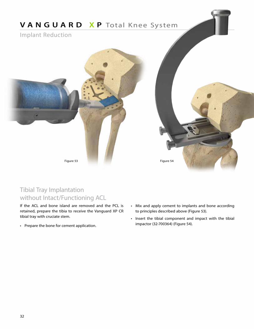
• Mix and apply cement to implants and bone according to principles described above (Figure 53).
• Insert the tibial component and impact with the tibial impactor (32-700364) (Figure 54).
Tibial Tray Implantation without Intact/Functioning ACLIf the ACL and bone island are removed and the PCL is retained, prepare the tibia to receive the Vanguard XP CR tibial tray with cruciate stem.
• Prepare the bone for cement application.
Implant Reduction
Figure 55
33
• Place the femoral component onto the end of the femoral impactor and insert it manually as far as possible.
• Fully seat the component onto the femur using the femoral impactor.
eXPert Advice: If the femoral component is not seated, the extension gap will be decreased, therefore increasing loads in full extension, and possibly increasing the risk for fracture of the bone island.
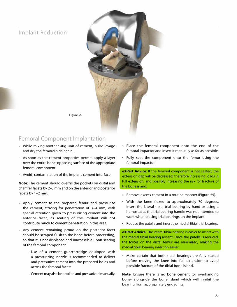
• Remove excess cement in a routine manner (Figure 55).
• With the knee flexed to approximately 70 degrees, insert the lateral tibial trial bearing by hand or using a hemostat as the trial bearing handle was not intended to work when placing trial bearings on the implant.
• Reduce the patella and insert the medial tibial trial bearing.
eXPert Advice: The lateral tibial bearing is easier to insert with the medial tibial bearing absent. Once the patella is reduced, the forces on the distal femur are minimized, making the medial tibial bearing insertion easier.
• Make certain that both tibial bearings are fully seated before moving the knee into full extension to avoid possible fracture of the tibial bone island.
Note: Ensure there is no bone cement (or overhanging bone) alongside the bone island which will inhibit the bearing from appropriately engaging.
Femoral Component Implantation• While mixing another 40g unit of cement, pulse lavage and dry the femoral side again.
• As soon as the cement properties permit, apply a layer over the entire bone-opposing surface of the appropriate femoral component.
• Avoid contamination of the implant-cement interface.
Note: The cement should overfill the pockets on distal and chamfer facets by 2–3 mm and on the anterior and posterior facets by 1–2 mm.
• Apply cement to the prepared femur and pressurize the cement, striving for penetration of 3–4 mm, with special attention given to pressurizing cement into the anterior facet, as seating of the implant will not contribute much to cement penetration in this area.
• Any cement remaining proud on the posterior facet should be scraped flush to the bone before proceeding, so that it is not displaced and inaccessible upon seating of the femoral component.
- Use of a cement gun/cartridge equipped with a pressurizing nozzle is recommended to deliver and pressurize cement into the prepared holes and across the femoral facets.
- Cement may also be applied and pressurized manually.
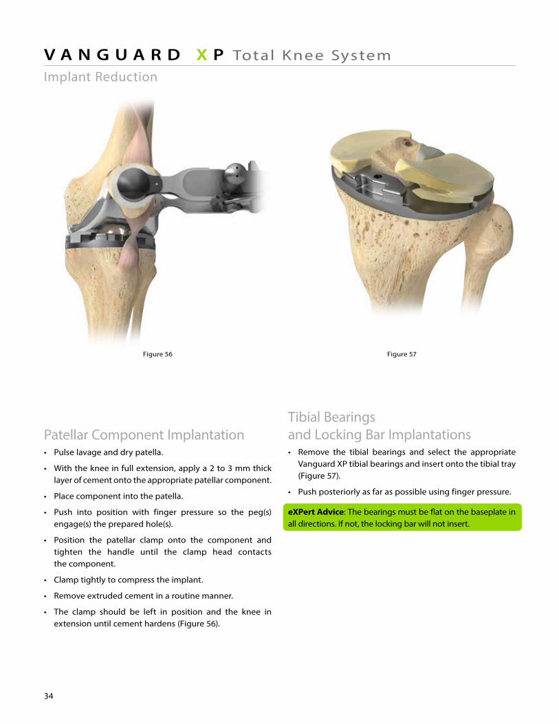
Figure 56 Figure 57
34
V A N G U A R D X P Total Knee System
Tibial Bearings and Locking Bar Implantations• Remove the tibial bearings and select the appropriate Vanguard XP tibial bearings and insert onto the tibial tray (Figure 57).
• Push posteriorly as far as possible using finger pressure.
eXPert Advice: The bearings must be flat on the baseplate in all directions. If not, the locking bar will not insert.
Patellar Component Implantation• Pulse lavage and dry patella.
• With the knee in full extension, apply a 2 to 3 mm thick layer of cement onto the appropriate patellar component.
• Place component into the patella.
• Push into position with finger pressure so the peg(s) engage(s) the prepared hole(s).
• Position the patellar clamp onto the component and tighten the handle until the clamp head contacts the component.
• Clamp tightly to compress the implant.
• Remove extruded cement in a routine manner.
• The clamp should be left in position and the knee in extension until cement hardens (Figure 56).
Implant Reduction
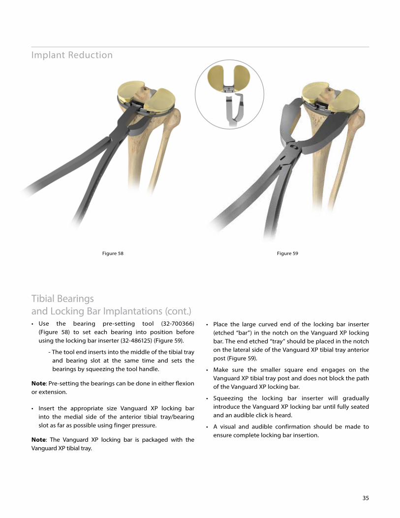
Figure 58 Figure 59
35
Implant Reduction
Tibial Bearings and Locking Bar Implantations (cont.)• Use the bearing pre-setting tool (32-700366) (Figure 58) to set each bearing into position before using the locking bar inserter (32-486125) (Figure 59).
- The tool end inserts into the middle of the tibial tray and bearing slot at the same time and sets the bearings by squeezing the tool handle.
Note: Pre-setting the bearings can be done in either flexion or extension.
• Insert the appropriate size Vanguard XP locking bar into the medial side of the anterior tibial tray/bearing slot as far as possible using finger pressure.
Note: The Vanguard XP locking bar is packaged with the Vanguard XP tibial tray.
• Place the large curved end of the locking bar inserter (etched “bar”) in the notch on the Vanguard XP locking bar. The end etched “tray” should be placed in the notch on the lateral side of the Vanguard XP tibial tray anterior post (Figure 59).
• Make sure the smaller square end engages on the Vanguard XP tibial tray post and does not block the path of the Vanguard XP locking bar.
• Squeezing the locking bar inserter will gradually introduce the Vanguard XP locking bar until fully seated and an audible click is heard.
• A visual and audible confirmation should be made to ensure complete locking bar insertion.

©2014 Biomet Orthopedics • Form No. BMET0922.1-ENG • REV0814
Legal ManufacturerBiomet Orthopedics56 E. Bell Drive P.O. Box 587Warsaw, Indiana 46581-0587 USA
www.biomet.com
Authorised RepresentativeBiomet UK Ltd.Waterton Industrial EstateBridgend, South WalesCF31 3XA UK
0086
This material is intended for health care professionals. Distribution to any other recipient is prohibited.
For complete product information, including indications, contraindications, warnings, precautions, and potential adverse effects, see the package insert and wwww.biomet.com.
Check for country product clearances and reference product specific instructions for use.
All content herein is protected by copyright, trademarks and other intellectual property rights owned by or licensed to Biomet Inc. or its affiliates unless otherwise indicated, and must not be redistributed, duplicated or disclosed, in whole or in part, without the express written consent of Biomet.
Biomet does not practice medicine. The treating surgeon is responsible for determining the appropriate treatment, technique(s), and product(s) for each individual patient. This technique was prepared in conjunction with licensed health care professionals.
Not for distribution in France.