Embed Size (px)
Citation preview
SynCageSurgical Technique

Image intensifier control
This description alone does not provide sufficient background for direct use of DePuy Synthes products. Instruction by a surgeon experienced in handling these products is highly recommended.
Processing, Reprocessing, Care and MaintenanceFor general guidelines, function control and dismantling of multi-part instruments, as well as processing guidelines for implants, please contact your local sales representative or refer to:http://emea.depuysynthes.com/hcp/reprocessing-care-maintenanceFor general information about reprocessing, care and maintenance of Synthes reusable devices, instrument trays and cases, as well as processing of Synthes non-sterile implants, please consult the Important Information leaflet (SE_023827) or refer to: http://emea.depuysynthes.com/hcp/reprocessing-care-maintenance
SynCage Surgical Technique DePuy Synthes 1
Table of contents
Product Overview Intended Use 2
Implant Description 3
Instrument Description 4
AO Spine Principles 5
Indications and Contraindications 10
Surgical Technique Preoperative Planning 11
Surgical Approach 11
Surgical Technique for Anterior Approach 12
Surgical Technique for Anterolateral Approach 18
Supplemental Posterior Stabilization 23
Postoperative Care 23
Product information Supplemental Instruments 24
Implants 25
Instruments 27
2 DePuy Synthes SynCage Surgical Technique
Product Overview
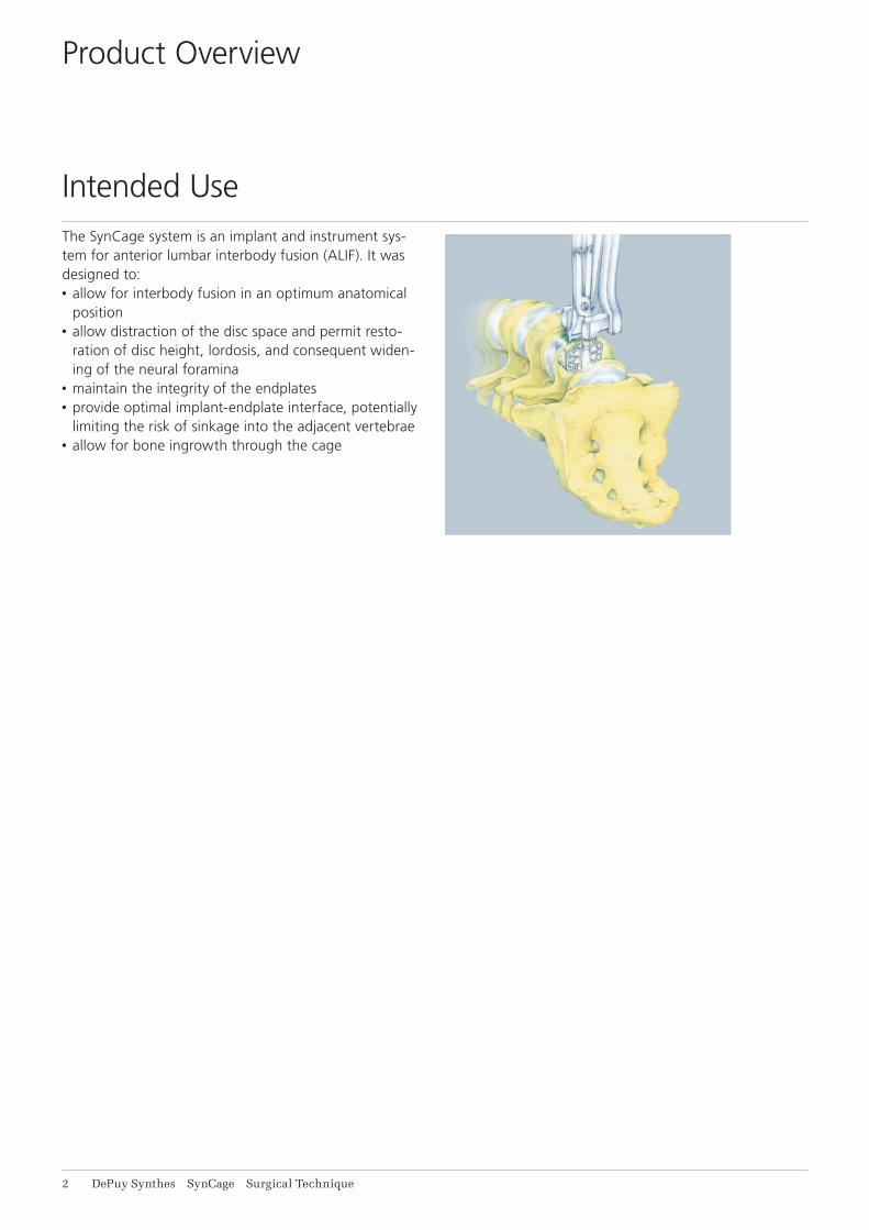
The SynCage system is an implant and instrument sys-tem for anterior lumbar interbody fusion (ALIF). It was designed to:• allow for interbody fusion in an optimum anatomical
position• allow distraction of the disc space and permit resto-
ration of disc height, lordosis, and consequent widen-ing of the neural foramina
• maintain the integrity of the endplates• provide optimal implant-endplate interface, potentially
limiting the risk of sinkage into the adjacent vertebrae• allow for bone ingrowth through the cage
Intended Use
SynCage Surgical Technique DePuy Synthes 3
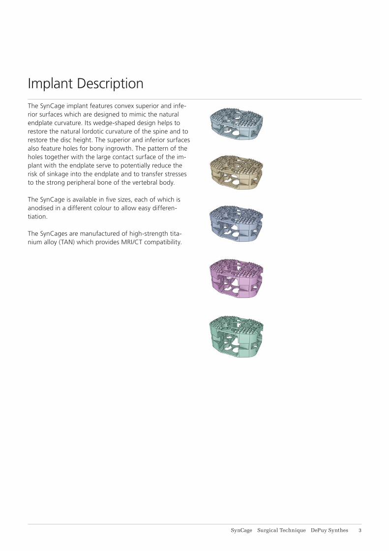
The SynCage implant features convex superior and infe-rior surfaces which are designed to mimic the natural endplate curvature. Its wedge-shaped design helps to restore the natural lordotic curvature of the spine and to restore the disc height. The superior and inferior surfaces also feature holes for bony in growth. The pattern of the holes together with the large contact surface of the im-plant with the endplate serve to potentially reduce the risk of sinkage into the endplate and to transfer stresses to the strong peripheral bone of the vertebral body.
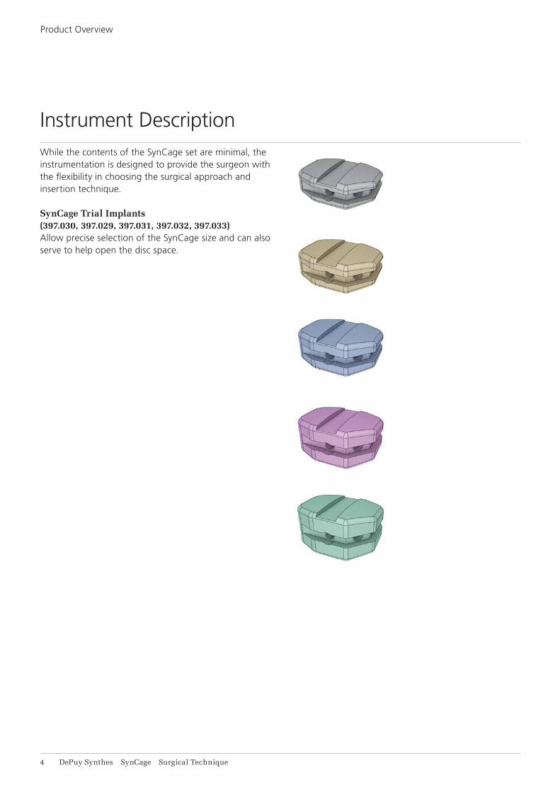
The SynCage is available in five sizes, each of which is anodised in a different colour to allow easy differen-tiation.
The SynCages are manufactured of high-strength tita-nium alloy (TAN) which provides MRI/CT compatibility.
Implant Description
4 DePuy Synthes SynCage Surgical Technique
While the contents of the SynCage set are minimal, the instrumentation is designed to provide the surgeon with the flexibility in choosing the surgical approach and insertion technique.
SynCage Trial Implants (397.030, 397.029, 397.031, 397.032, 397.033)Allow precise selection of the SynCage size and can also serve to help open the disc space.
Product Overview
Instrument Description

coronalaxial
sagittal
SynCage Surgical Technique DePuy Synthes 1
The four principles to be considered as the foundation for proper spine patient management underpin the design and delivery of the Curriculum: Stability – Alignment – Biology – Function.1,2
StabilityStabilization to achieve a specifi c therapeutic out-come
BiologyEtiology, pathogenesis, neural protection, and tissue healing
AlignmentBalancing the spine in three dimensions
FunctionPreservations and resto-ration of function to pre-vent disability
AO Spine Principles
Copyright © 2012 by AOSpine
1 Aebi M, Thalgott JS, Webb JK (1998): AO ASIF Principles in Spine Surgery. Berlin: Springer.
2 Aebi M, Arlet V, Webb JK, (2007): AOSPINE Manual (2 vols), Stuttgart, New York: Thieme.
6 DePuy Synthes SynCage Surgical Technique
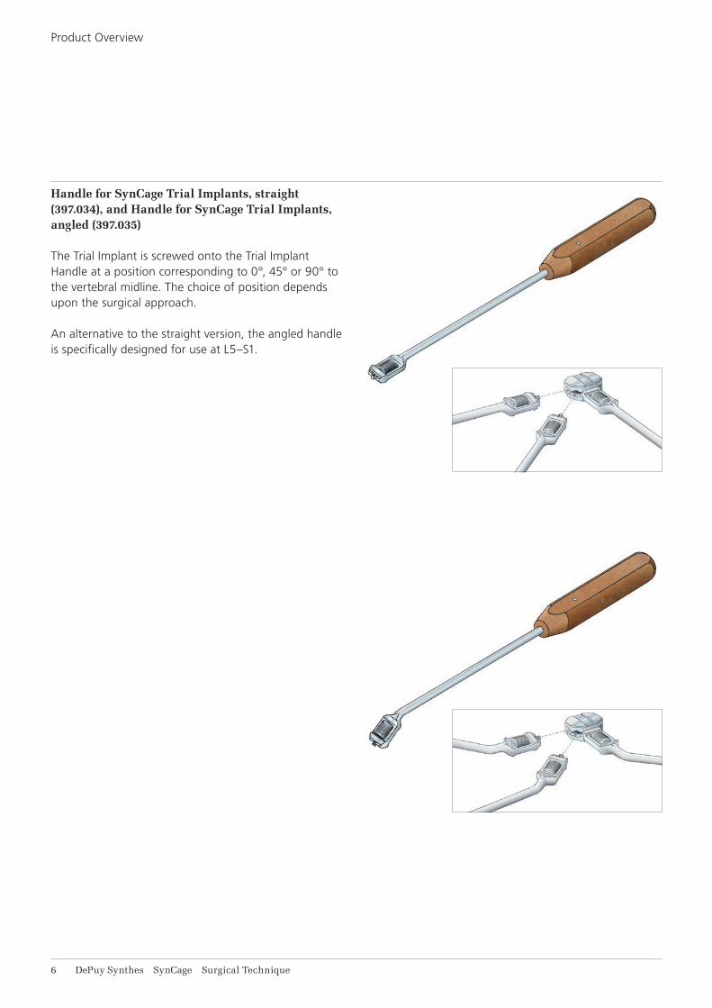
Handle for SynCage Trial Implants, straight (397.034), and Handle for SynCage Trial Implants, angled (397.035)
The Trial Implant is screwed onto the Trial Implant Handle at a position corresponding to 0°, 45° or 90° to the vertebral midline. The choice of position depends upon the surgical approach.
An alternative to the straight version, the angled handle is specifically designed for use at L5–S1.
Product Overview
SynCage Surgical Technique DePuy Synthes 7
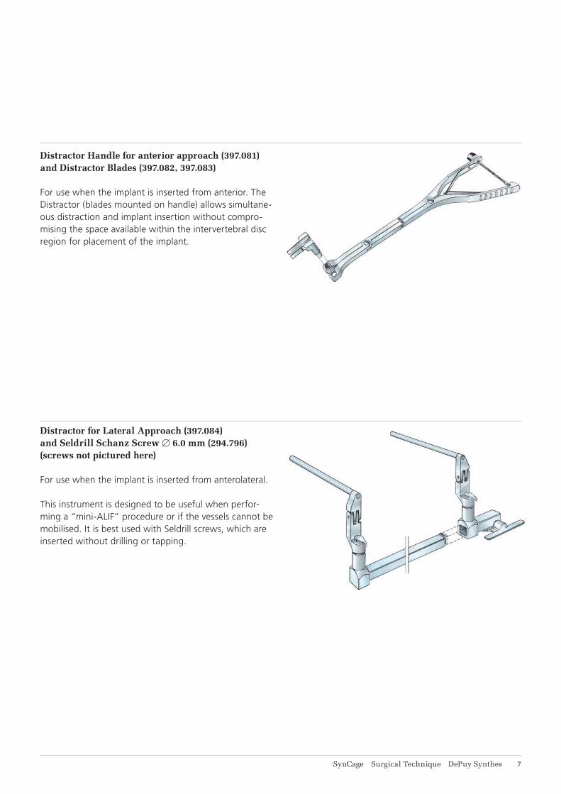
Distractor Handle for anterior approach (397.081) and Distractor Blades (397.082, 397.083)
For use when the implant is inserted from anterior. The Distractor (blades mounted on handle) allows simultane-ous distraction and implant insertion without compro-mising the space available within the intervertebral disc region for placement of the implant.
Distractor for Lateral Approach (397.084) and Seldrill Schanz Screw 6.0 mm (294.796) (screws not pictured here)
For use when the implant is inserted from anterolateral.
This instrument is designed to be useful when perfor-ming a “mini-ALIF” procedure or if the vessels cannot be mobilised. It is best used with Seldrill screws, which are inserted without drilling or tapping.
A
8 DePuy Synthes SynCage Surgical Technique
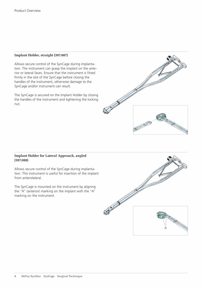
Implant Holder, straight (397.087)
Allows secure control of the SynCage during implanta-tion. The instrument can grasp the implant on the ante-rior or lateral faces. Ensure that the instrument is fitted firmly in the slot of the SynCage before closing the handles of the instrument, otherwise damage to the SynCage and/or instrument can result.
The SynCage is secured on the Implant Holder by closing the handles of the instrument and tightening the locking nut.
Implant Holder for Lateral Approach, angled (397.088)
Allows secure control of the SynCage during implanta-tion. This instrument is useful for insertion of the implant from anterolateral.
The SynCage is mounted on the instrument by aligning the “A” (anterior) marking on the implant with the “A” marking on the instrument.
Product Overview
SynCage Surgical Technique DePuy Synthes 9
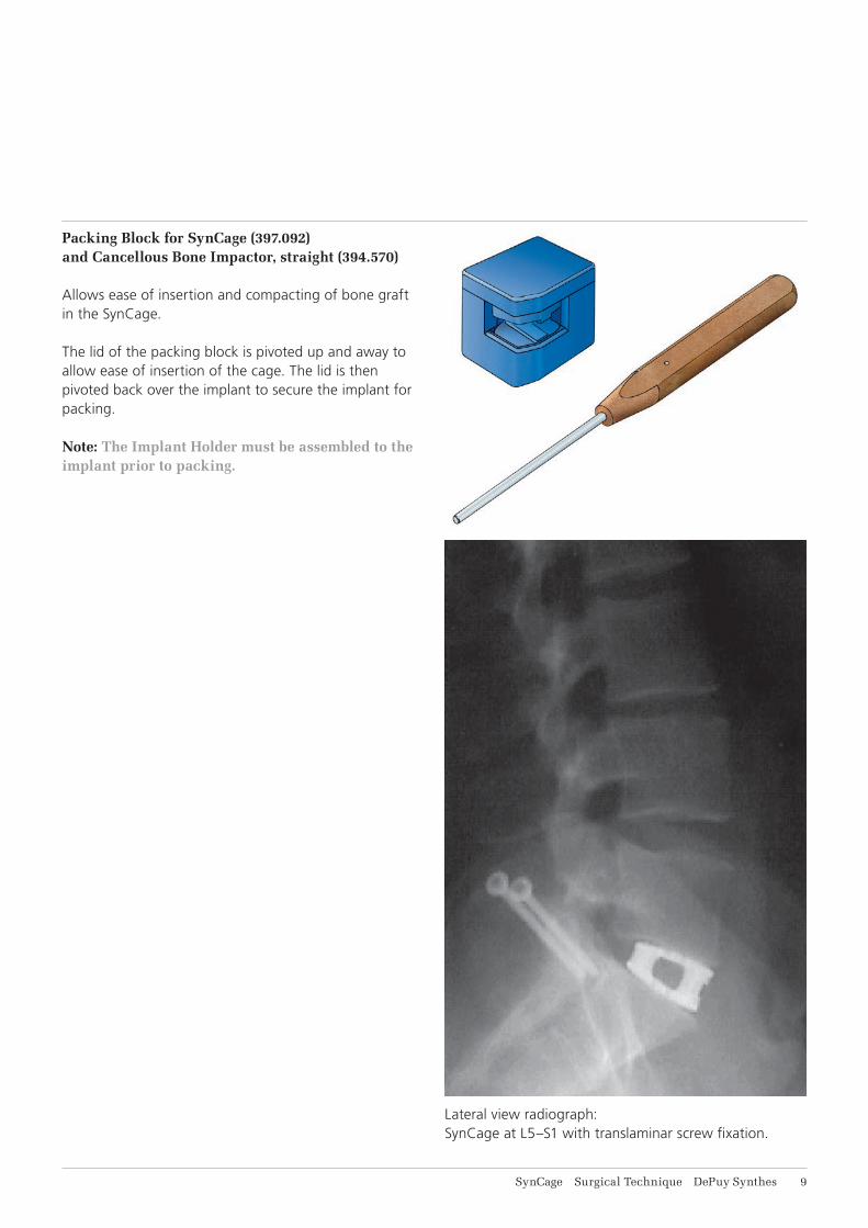
Packing Block for SynCage (397.092) and Cancellous Bone Impactor, straight (394.570)
Allows ease of insertion and compacting of bone graft in the SynCage. The lid of the packing block is pivoted up and away to allow ease of insertion of the cage. The lid is then pivoted back over the implant to secure the implant for packing.
Note: The Implant Holder must be assembled to the implant prior to packing.
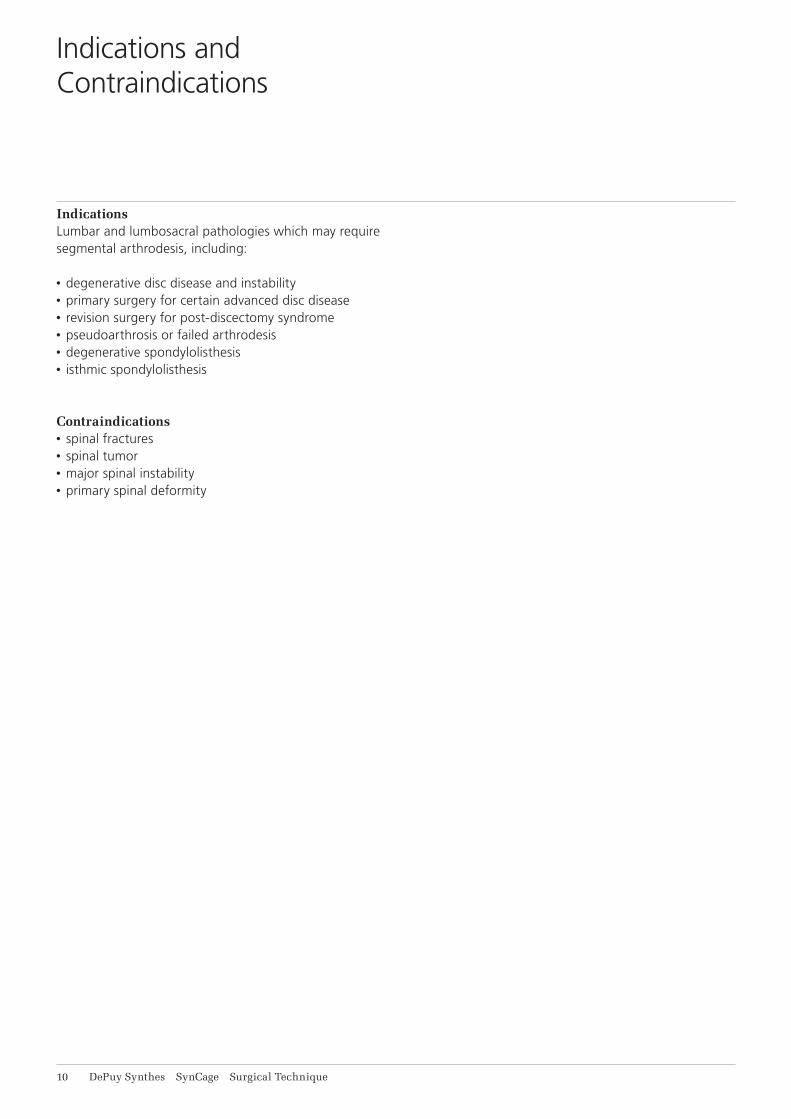
Lateral view radiograph: SynCage at L5–S1 with translaminar screw fixation.
11 DePuy Synthes SynCage Surgical Technique
IndicationsLumbar and lumbosacral pathologies which may require segmental arthrodesis, including:
• degenerative disc disease and instability• primary surgery for certain advanced disc disease• revision surgery for post-discectomy syndrome• pseudoarthrosis or failed arthrodesis• degenerative spondylolisthesis• isthmic spondylolisthesis
Contraindications• spinal fractures• spinal tumor• major spinal instability• primary spinal deformity
Indications and Contraindications
SynCage Surgical Technique DePuy Synthes 11
Surgical Technique
Prior to surgery, the desired surgical approach and an es-timation of the appropriate SynCage size is determined. The desired surgical approach is dependent on the level to be treated and the surgeon’s preference. As the Syn-Cage can be inserted from either the anterior or antero-lateral direction, the surgeon is free to use the approach of choice. The technique for insertion of the SynCage varies slightly depending on the direction chosen.
An initial estimate of the SynCage size can be deter-mined by comparing the SynCage Radiograph Template (0330.060) with the adjacent intervertebral discs on a lateral radiograph. The height of the template is 1 mm (half the height of the two sets of teeth) shorter than that of the respective SynCage to account for penetra-tion of the teeth into the vertebral bone.
The SynCage must fit firmly with a tight press-fit be-tween the endplates with the segment fully distracted. It is essential that the tallest possible SynCage be used so as to enhance the stability of the segment resulting from tension in the ligament and annulus fibrosus.
The patient is positioned as required for the chosen ap proach. For treatment of the lower lumbar levels from anterior the patient is placed in the Trendelenburg position. If the SynCage is to be introduced anterolaterally, for example at higher levels of the lumbar spine, the patient is placed in either a supine or lateral decubitus position.
Preoperative Planning
Surgical Approach
12 DePuy Synthes SynCage Surgical Technique
1. Attain exposure
For anterior insertion, the intervertebral disc is exposed such that there is a clear space on either side of the ver-tebral midline equal to half the width of the SynCage. If the vessels and/or tissues cannot be retracted suffi-ciently, insertion from anterolateral direction may be indicated.
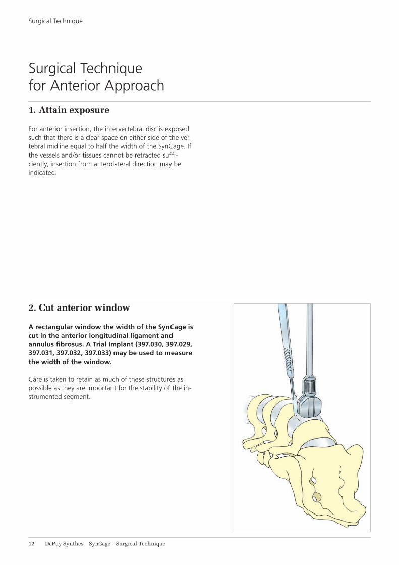
2. Cut anterior window
A rectangular window the width of the SynCage is cut in the anterior longitudinal ligament and annulus fibrosus. A Trial Implant (397.030, 397.029, 397.031, 397.032, 397.033) may be used to measure the width of the window.
Care is taken to retain as much of these structures as possible as they are important for the stability of the in-strumented segment.
Surgical Technique for Anterior Approach
Surgical Technique
SynCage Surgical Technique DePuy Synthes 13
3. Prepare the disc space
Through the window in the anterior longitudinal liga-ment and annulus fibrosus, the disc material is excised and the superficial layers of the cartilaginous endplates removed such that bleeding bone is attained. Adequate cleaning of the endplate is important for vascular supply to the bone graft, however, excessive cleaning may weaken the endplate due to removal of the denser bone of the endplate. If possible, the endplate is prepared such that its curvature matches that of the superior and inferior surfaces of the implant.
Once the endplates have been prepared and any addi-tional surgical procedures completed, the SynCage is in-troduced into the intervertebral space as follows.
Notes: • It is essential that enough material is removed
from the intervertebral disc to accommodate the SynCage, otherwise disc material may be dis-placed posteriorly during insertion of the implant.
• Excessive removal of the subchondral bone may weaken the vertebral endplate. If the entire end-plate is removed, subsidence and loss of segmental stability may result.
14 DePuy Synthes SynCage Surgical Technique
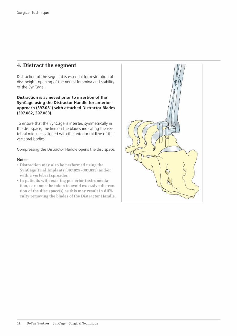
4. Distract the segment
Distraction of the segment is essential for restoration of disc height, open ing of the neural foramina and stability of the SynCage.
Distraction is achieved prior to insertion of the SynCage using the Distractor Handle for anterior approach (397.081) with attached Distractor Blades (397.082, 397.083).
To ensure that the SynCage is inserted symmetrically in the disc space, the line on the blades indicating the ver-tebral midline is aligned with the anterior midline of the vertebral bodies.
Compressing the Distractor Handle opens the disc space.
Notes: • Distraction may also be performed using the
SynCage Trial Implants (397.029–397.033) and/or with a vertebral spreader.
• In patients with existing posterior instrumenta-tion, care must be taken to avoid excessive distrac-tion of the disc space(s) as this may result in diffi-culty removing the blades of the Distractor Handle.
Surgical Technique

SynCage Surgical Technique DePuy Synthes 11
6. Select the implant
The SynCage corresponding to the Trial Implant is then selected.
The SynCages are colour-coded by height:
Size Item No. Colour
XXS 495.508 light blue
Extra-small 495.307 gold
Small 495.309 dark blue
Medium 495.311 violet
Large 495.313 green
With the SynCage of the correct height chosen, it is se-cured on the straight Implant Holder (397.087).
5. Trial for implant size
The Trial Implant that corresponds with the SynCage size determined during the preoperative planning is selected and attached to the straight Handle for SynCage Trial Implants (397.034).
The Trial Implant is slid between the Distractor Blades into the disc space.
If a tight fit is not achieved, try the next larger size. If the Trial Implant cannot be inserted, try the next smaller size. With the segment fully distracted, the SynCage/Trial Im-plant must fit firmly with a tight press-fit between the endplates such that disc height is not lost once the Distractor is removed.
Once the size of SynCage has been selected, the distrac-tion is temporarily relaxed.
Precaution: The SynCage Trial Implants are not for implantation and must be removed before insertion of the SynCage.
16 DePuy Synthes SynCage Surgical Technique
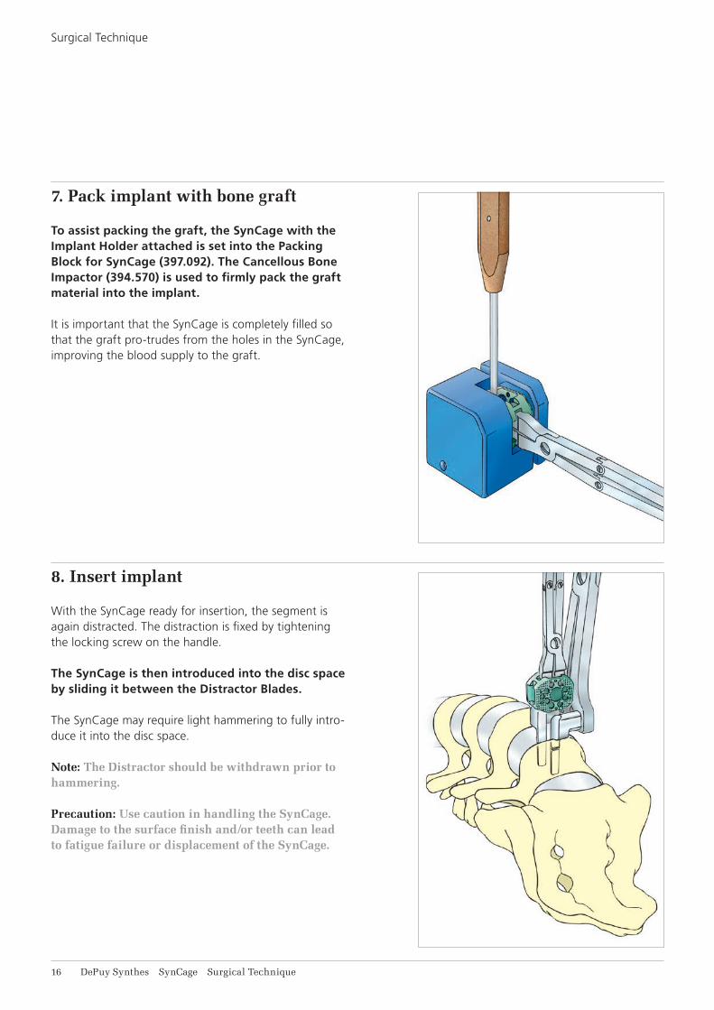
7. Pack implant with bone graft
To assist packing the graft, the SynCage with the Implant Holder attached is set into the Packing Block for SynCage (397.092). The Cancellous Bone Impactor (394.570) is used to firmly pack the graft material into the implant.
It is important that the SynCage is completely filled so that the graft pro-trudes from the holes in the SynCage, improving the blood supply to the graft.
8. Insert implant
With the SynCage ready for insertion, the segment is again distracted. The distraction is fixed by tightening the locking screw on the handle.
The SynCage is then introduced into the disc space by sliding it between the Distractor Blades.
The SynCage may require light hammering to fully intro-duce it into the disc space.
Note: The Distractor should be withdrawn prior to hammering.
Precaution: Use caution in handling the SynCage. Damage to the surface finish and/or teeth can lead to fatigue failure or displacement of the SynCage.
Surgical Technique
SynCage Surgical Technique DePuy Synthes 17
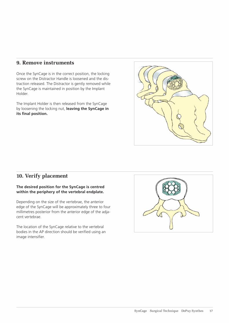
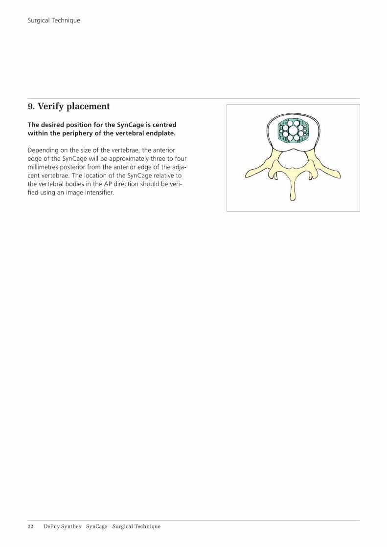
10. Verify placement
The desired position for the SynCage is centred within the periphery of the vertebral endplate.
Depending on the size of the vertebrae, the anterior edge of the SynCage will be approximately three to four millimetres posterior from the anterior edge of the adja-cent vertebrae.
The location of the SynCage relative to the vertebral bodies in the AP direction should be verified using an image intensifier.
9. Remove instruments
Once the SynCage is in the correct position, the locking screw on the Distractor Handle is loosened and the dis-traction released. The Distractor is gently removed while the SynCage is maintained in position by the Implant Holder.
The Implant Holder is then released from the SynCage by loosening the locking nut, leaving the SynCage in its final position.
18 DePuy Synthes SynCage Surgical Technique
1. Insert Seldrill screws
Once exposure of the intervertebral disc is attained, the surrounding tissues and vessels retracted and the disc space prepared, a Seldrill Schanz Screw 6.0 mm, Stain-less Steel (294.796) is inserted into each of the vertebral bodies adjacent to the disc to be treated. These screws are self-drilling and self-tapping and should be inserted under low power, high torque. These screws should be introduced parallel to each other. Care must be taken to ensure that they are not inserted too deeply.
Note: This is an abbreviated text. Surgical technique steps common to the anterior approach are not re-peated in detail here.
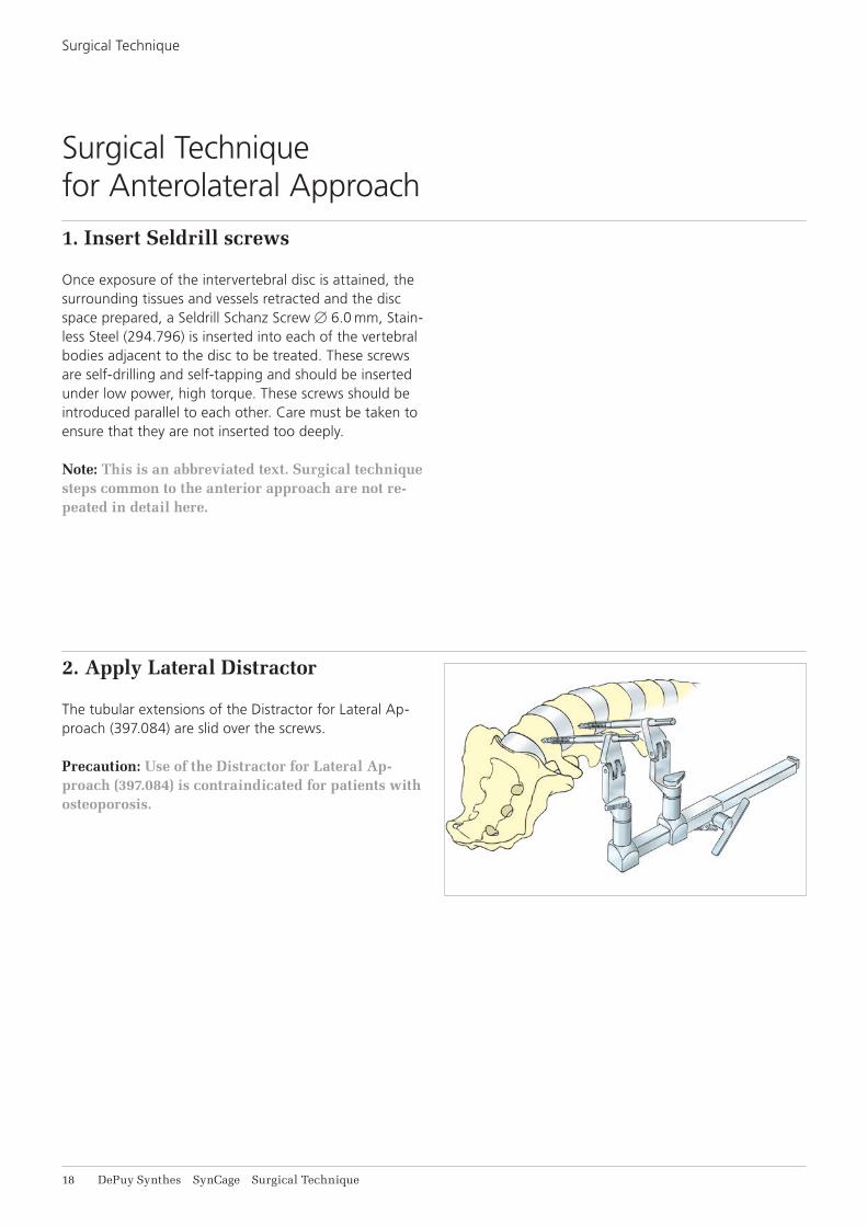
2. Apply Lateral Distractor
The tubular extensions of the Distractor for Lateral Ap-proach (397.084) are slid over the screws.
Precaution: Use of the Distractor for Lateral Ap-proach (397.084) is contraindicated for patients with osteoporosis.
Surgical Technique for Anterolateral Approach
Surgical Technique
SynCage Surgical Technique DePuy Synthes 19
3. Distract the segment
The vertebral segment is distracted by turning the knob of the Distractor.
If necessary, additional distraction may be achieved using a vertebral spreader to open the space, using then the Lateral Distractor to hold the distraction. Trial Im-plants may also be used to help open the segment.
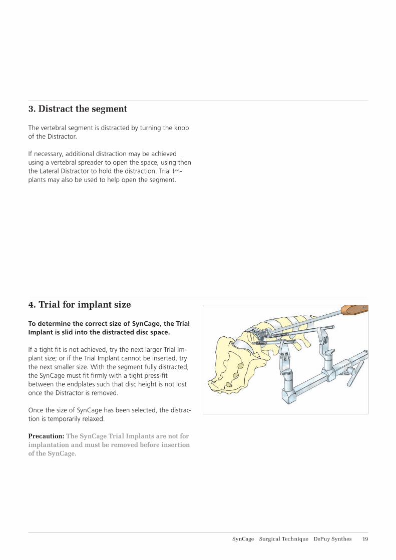
4. Trial for implant size
To determine the correct size of SynCage, the Trial Implant is slid into the distracted disc space.
If a tight fit is not achieved, try the next larger Trial Im-plant size; or if the Trial Implant cannot be inserted, try the next smaller size. With the segment fully distracted, the SynCage must fit firmly with a tight press-fit between the endplates such that disc height is not lost once the Distractor is removed.
Once the size of SynCage has been selected, the distrac-tion is temporarily relaxed.
Precaution: The SynCage Trial Implants are not for implantation and must be removed before insertion of the SynCage.
21 DePuy Synthes SynCage Surgical Technique
5. Select implant
The SynCage corresponding to the Trial Implant is then selected. The SynCages are colour-coded by height:
Size Item No. Colour
XXS 495.508 light blue
Extra-small 495.307 gold
Small 495.309 dark blue
Medium 495.311 violet
Large 495.313 green
With the SynCage of the correct height chosen, it is se-cured on the desired Implant Holder. Depending on the angle of the approach the SynCage is introduced with either the Implant Holder for Lateral Approach (397.088), or the straight Implant Holder (397.087).
For SynCage XXS (495.508) use the Implant Holder for SynCage XXS, straight (397.111).
6. Pack implant with bone graft
The SynCage is then packed with bone graft as pre-viously described (page 16).
Surgical Technique
SynCage Surgical Technique DePuy Synthes 21
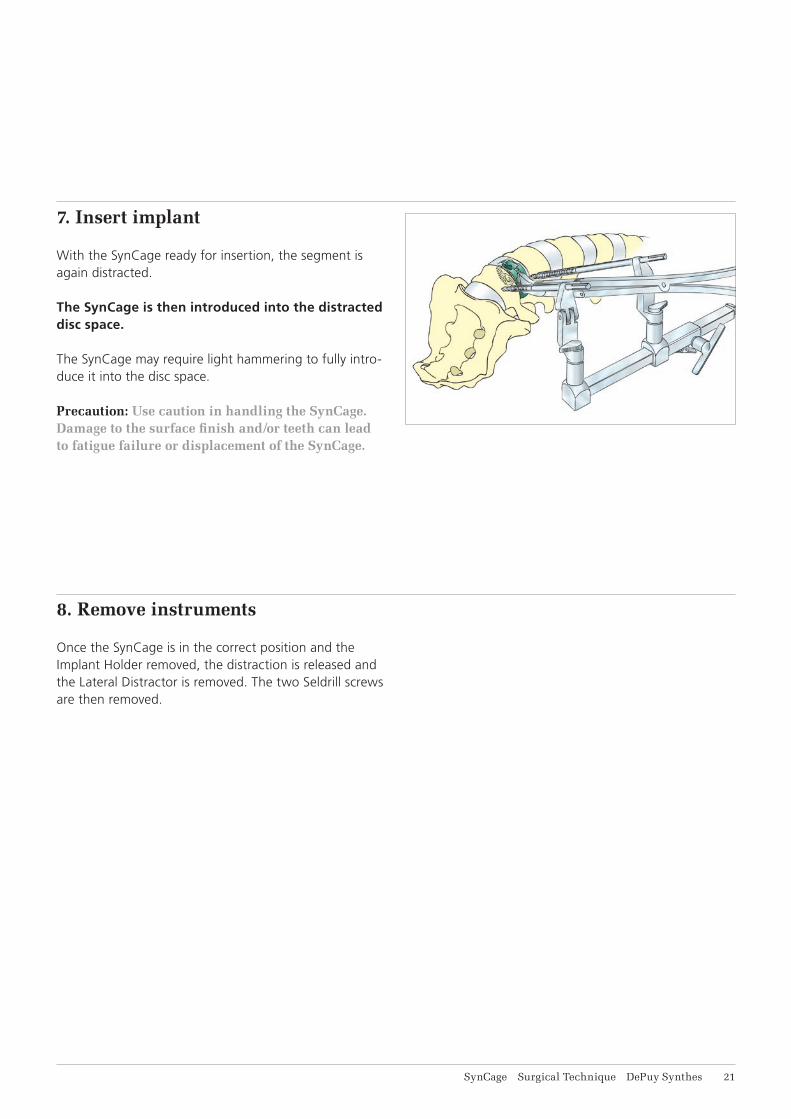
7. Insert implant
With the SynCage ready for insertion, the segment is again distracted.
The SynCage is then introduced into the distracted disc space.
The SynCage may require light hammering to fully intro-duce it into the disc space.
Precaution: Use caution in handling the SynCage. Damage to the surface finish and/or teeth can lead to fatigue failure or displacement of the SynCage.
8. Remove instruments
Once the SynCage is in the correct position and the Implant Holder removed, the distraction is released and the Lateral Distractor is removed. The two Seldrill screws are then removed.
22 DePuy Synthes SynCage Surgical Technique
9. Verify placement
The desired position for the SynCage is centred within the periphery of the vertebral endplate.
Depending on the size of the vertebrae, the anterior edge of the SynCage will be approximately three to four millimetres posterior from the anterior edge of the adja-cent vertebrae. The location of the SynCage relative to the vertebral bodies in the AP direction should be veri-fied using an image intensifier.
Surgical Technique
SynCage Surgical Technique DePuy Synthes 23
For treatment of spondylolisthesis, the use of a supple-mental pedicle screw construct is indicated. In such cases, the posterior procedure is performed first. Care must then be taken to ensure that the disc space is not excessively distracted as this may cause difficulty in removing the blades of the distraction instrument.
Note: In patients with existing posterior intrumenta-tion, care must be taken to avoid excessive distrac-tion of the disc space(s) as this may result in diffi-culty removing the blades of the Distractor Handle.
The patients can be mobilised one day after surgery. A brace (T.L.S.O. or L.S.O.) is recommended to be worn for the first three months postoperatively. The patients should be cautioned against activities that place unrea-sonable stress on the region. Excessive physical activity and trauma affecting the involved vertebrae may cause premature failure through loosening and/or fracture of the endplate.
Supplemental Posterior Stabilization
Postoperative Care
24 DePuy Synthes SynCage Surgical Technique
Other instruments which may be useful during the SynCage procedure include:
• Universal Chuck with T-Handle (393.100) if standard Schanz Screw 6.0 mm (294.680) are used with the Lateral Distractor and are inserted manually.
• Cancellous Bone Impactor B 8.0 mm (397.730) and Handle with Quick Coupling (397.700) a larger version of the Cancellous Bone Impactor (394.570).
• Bone Spreader (399.100, 399.130) spreaders that can be used to distract the vertebral segment.
• Hammer 500 g/700 g (399.420, 399.430) for final seating of the implant and for packing bone graft into the implant.
• Spinal Instruments for Anterior Surgery a range of instruments specifically designed for the requirements of anterior spinal surgery. Included are Punches, Rongeurs and Curettes.
Supplemental Instruments

SynCage Surgical Technique DePuy Synthes 21
Implants
495.508 SynCage XXS, 12 24 30 mm
495.307 SynCage, Extra-small, anterior/posterior height 13.5/8.5 mm, Titanium Alloy (TAN), gold
495.309 SynCage, small, anterior/posterior height 15.0/10.0 mm, Titanium Alloy (TAN), dark blue
495.311 SynCage, medium, anterior/posterior height 17.0/12.0 mm, Titanium Alloy (TAN), violet
495.313 SynCage, large, anterior/posterior height 19.0/14.0 mm, Titanium Alloy (TAN), green
26 DePuy Synthes SynCage Surgical Technique
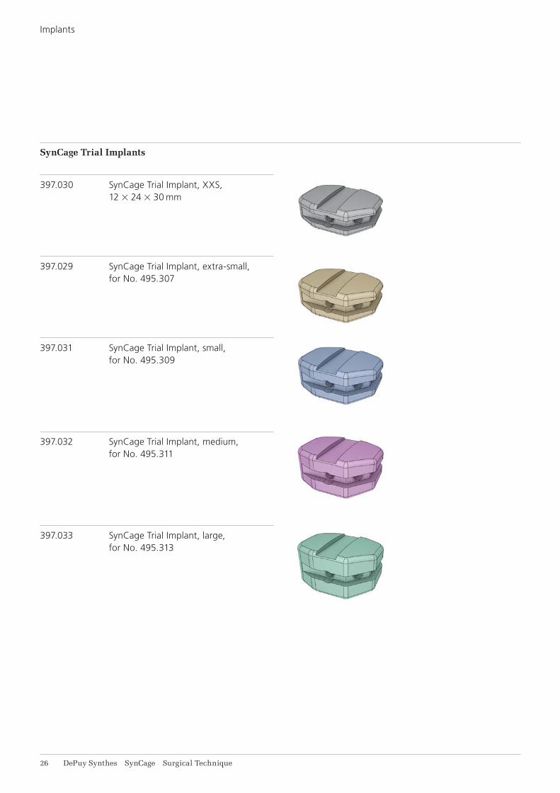
SynCage Trial Implants
397.030 SynCage Trial Implant, XXS, 12 24 30 mm
397.029 SynCage Trial Implant, extra-small, for No. 495.307
397.031 SynCage Trial Implant, small, for No. 495.309
397.032 SynCage Trial Implant, medium, for No. 495.311
397.033 SynCage Trial Implant, large, for No. 495.313
Implants
SynCage Surgical Technique DePuy Synthes 27
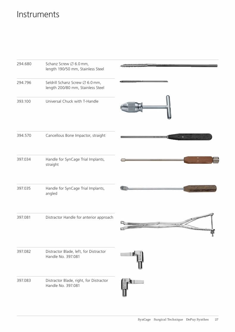
294.680 Schanz Screw 6.0 mm, length 190/50 mm, Stainless Steel
294.796 Seldrill Schanz Screw 6.0 mm, length 200/80 mm, Stainless Steel
393.100 Universal Chuck with T-Handle
394.570 Cancellous Bone Impactor, straight
397.034 Handle for SynCage Trial Implants, straight
397.035 Handle for SynCage Trial Implants, angled
397.081 Distractor Handle for anterior approach
397.082 Distractor Blade, left, for Distractor Handle No. 397.081
397.083 Distractor Blade, right, for Distractor Handle No. 397.081
Instruments

28 DePuy Synthes SynCage Surgical Technique
397.084 Distractor for Lateral Approach, for SynCage
397.087 Implant Holder, straight, for SynCage
397.088 Implant Holder for Lateral Approach, angled, for SynCage
397.092 Packing Block for SynCage
397.111 Implant Holder for SynCage XXS, straight
397.700 Handle with Quick Coupling
397.730 Cancellous Bone Impactor 8.0 mm, round
Instruments
SynCage Surgical Technique DePuy Synthes 29
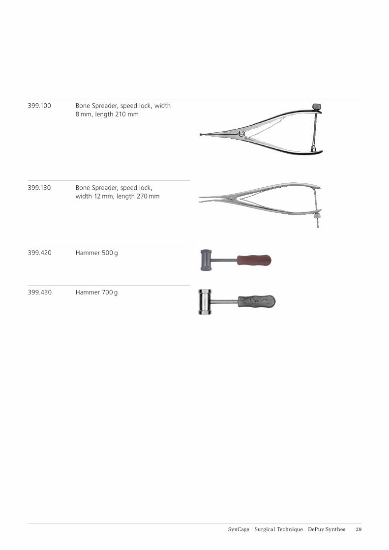
399.100 Bone Spreader, speed lock, width 8 mm, length 210 mm
399.130 Bone Spreader, speed lock, width 12 mm, length 270 mm
399.420 Hammer 500 g
399.430 Hammer 700 g

0123
Synthes GmbHEimattstrasse 34436 OberdorfSwitzerlandTel: +41 61 965 61 11Fax: +41 61 965 66 00www.depuysynthes.com ©
DeP
uy S
ynth
es S
pine
, a d
ivis
ion
of S
ynth
es G
mbH
. 201
7.
All
right
s re
serv
ed.
036.
000.
491
DS
EM
/SP
N/0
814/
0161
(2)
08/1
7
Not all products are currently available in all markets.
This publication is not intended for distribution in the USA.
All surgical techniques are available as PDF files at www.depuysynthes.com/ifu