Embed Size (px)
Citation preview

Optimal Approach
SurgicalTechnique
Unicompartmental Knee System
HLS Uni Evolution

CONTENTS
1. DESIGN RATIONALE
2. TIBIAL PREPARATION
1. Use of Patellar Retractors
2. Assembly of Tibial Cutting Guide
3. Adjustment of posterior slope
4. Adjustment in the frontal plane
5. Determination of tibial resection level
6. Resection of the proximal tibia
7. Trialing
3. FEMORAL PREPARATION
1. Insert the Femoral Guide for Condyle Positioning
2. Position the Femoral Drill Guide
3. Determine correct orientation of the Femoral Drill Guide
a/ Medio-lateral
b/ Rotation
4. Preparation of the fin slot
5. Femoral sizing
6. Secure the Condyle Cutting Guide to the condyle
7. Femoral Chamfer cuts
4. TRIAL REDUCTION
1. Trial components
2. Static test in extension
3. Dynamic test
5. COMPONENT IMPLANTATION
INSTRUMENTS
IMPLANTS
CONTENTS
p. 4p. 4
p. 11
p. 16p. 17p. 24
p. 15
2
HLS
Uni
Evo
lutio
n O
ptim
al A
ppro
ach
33
INTRODUCTION
Proper patient selection and accurate use instruments are critical to the success of unicompartmental knee arthroplasty1,2.
Since 1987, the HLS UNI knee has been implanted in thousands of patients worldwide. Results of the HLS UNIknee were included in the multi-centric study presented at SOFCOT 1995, and have been reported in recentpublications3,4.The 20 years of clinical success prove the excellence of the original HLS UNI design. These outstanding results also emphasize the critical role of ancillary instruments.
Our new Optimal Approach instrumentation is the summation of the clinical experience of several surgeonsrenowned as experts in unicompartmental knee arthroplasty (UKA).It has been specially designed for minimally invasive knee surgery.
We therefore have a combination of proven implants and well-thought instruments that meet all requirements of medial and lateral unicompartmental knee arthroplasty5.
Indications: The HLS Uni Evolution system is indicated for the replacement of the medial or lateral compartmentof the femorotibial knee joint when only one compartment is affected. This device is indicated for treatment of primary or secondary femorotibial Osteoarthritis. The HLS Uni Evolution prosthesis is intended for cementeduse only.
Known contraindications to date: Ligamentous instability of the knee. Failure of one or both cruciate ligaments.Important axial deformation of the knee. Obesity. Chondrocalcinosis. Patello femoral problem. Systemic infectionis an absolute contraindication. Every effort should be made to rule out the possibility of preoperative sepsis in a patient who has one or more of the following abnormalities: fever and/or local inflammation;rapid joint destruction or bone resorption apparent or roentgenograms and elevation of sedimentation rateunexplained by other disease, elevation of WBC count. Distant foci of infection from genitourinary, pulmonary,skin and other sites, dental focus infection which may cause hematogenous spread to the implant site.Skeletally immature patients. Cases where there is inadequate neuromuscular status, poor bone stock, or poorskin coverage around the knee joint that would make the procedure unjustifiable. Neuromuscular or psychiatricdisorders which might jeopardise fixation and postoperative care. Known allergy to one of the materials.Pregnancy.
1How to select candidates for lateral unicompartimentalprosthesis. E. Servien, PCM Verdonk, T. Aït Si Selmi, P. NeyretCentre Livet, Lyon, France). Techniques in Knee Surgery 2006
2The ideal candidate: Indications and limitations ofunicompartimental knee replacement : Gérard Deschamps.Unicompartimental Knee Arthroplasty SOFCOT 1995 RCO 1996
3Results at 6 years minimum Follow-up of a continuous series of 113 Unicompartimental Kenne Arthroplasties ISAKOS 2005Laurent Jacquot, Gérard Deschamps
4Résultats d’une série consécutive de 100 prothèsesunicompartimentales du genou avec un recul moyen de 5 ans.Jean-Luc Paillot, Elvire Servien, Tarik Aït Si Selmi, Philippe Neyret.Revue de Chirurgie Orthopédique (vol 92 suppl. n° 6 octobre 2006)
5Results of lateral 81 UKR at 6 years mean follow_up ESSKA 2002R. Badet, K. Baïtour, T. Aït Si Selmi, H. Dejour, P.Neyret
INTRODUCTION
HLS
Uni
Evo
lutio
n O
ptim
al A
ppro
ach

1 Use of Patellar Retractors
Patellar Retractors have been specially designedto retract the patella either medially or laterally:• Insert the claw into the femoral notch.• Press the wing on the patella to shift it medially
or laterally.The curved handle facilitates insertion through a miniincision.
DESIGN RATIONALE1. DESIGN RATIONALE
TIBIAL PREPARATION2. TIBIAL PREPARATION
The HLS UNI EVOLUTION knee consistsof a symmetric cobalt chromium (CoCr) femoral component, and an all-polyethylene (PE) tibial component.
The resurfacing femoral component with its specificsagittal radius of curvature allows minimal bone sacrifice.Broad M/L radius in coronal plane provides better loaddistribution on PE, which decreases its potential wear.The femoral component has a tapered anterior tipwhich prevents patellar impingement during flexion.The small cylindrical fixation peg is reinforced with a thin extended fin.The peg and posterior condylar surface are inclinedby 15 degrees to increase flexion and significantlydecrease the push-out forces in hyperflexion.
4
HLS
Uni
Evo
lutio
n O
ptim
al A
ppro
ach

2 Assembly of Tibial Cutting Guide
• Slide the Tibial Cutting Guide down the Jig for TibialCut.
• Assemble the Malleolar Clamp to the distal end of the Alignement Jig for Tibial Cut. (fig. 01)
• Raise the top of the Cutting Guide 5 mm above the Central Positioning Hole, and tighten screw #1.
• Center the Malleolar Clamp over the ankle, proximal to the malleoli, and tighten screw #3. (fig. 02)
• Adjust the height of the Telescopic Alignment Rod to the length of the tibia and tightenscrew #2. (fig. 03)
The Central Positioning Hole of the Cutting Guideshould sit 15 mm below the tibial intercondylareminence.
5
HLS
Uni
Evo
lutio
n O
ptim
al A
ppro
ach
(fig. 01)
(fig. 02)
(fig. 03)
Screw #1
Screw #3
Screw #2
2. TIBIAL PREPARATION
TIBIAL PREPARATION

HLS
Uni
Evo
lutio
n O
ptim
al A
ppro
ach 3 Adjustment of posterior slope
The cutting guide is built with 5° of posterior inclination.However, the Optimal Approach Instrumentation alsooffers the possibility of replicating the natural slopeof the patient's knee:
• Insert the Joint Line Probe Pin into the CentralPositioning Hole of the Cutting Guide.
• Loosen screws #1 and #3. (fig 04)
• Slide the Alignment Rod anteriorly or posteriorly at the Malleolar Clamp to bring the Joint Line ProbePin into contact with both anterior and posteriormargins of the tibial plateau. (fig. 05)
• Tighten screws #1 and #3.
• Drive the 3 mm Flat Ended Drill through the Central Positioning Hole. (fig. 06a)
Caution: Check that the Extra Medullary rod is alignedperpendicular to the frontal plane.• Insert the 110 mm Fixation Pin. (fig. 06b)
6
(fig. 04)
(fig. 05)
(fig. 06a)
(fig. 06b)
2. TIBIAL PREPARATION
TIBIAL PREPARATION
Screw #7
Screw #3
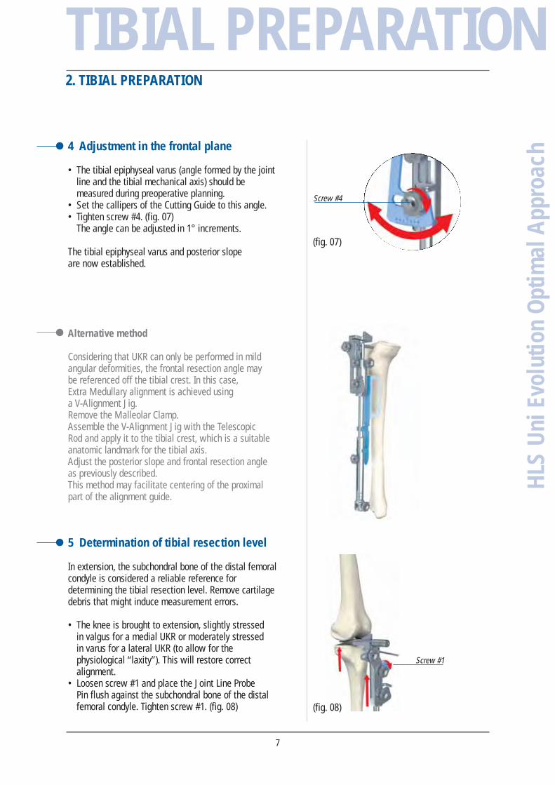
4 Adjustment in the frontal plane
• The tibial epiphyseal varus (angle formed by the jointline and the tibial mechanical axis) should bemeasured during preoperative planning.
• Set the callipers of the Cutting Guide to this angle.• Tighten screw #4. (fig. 07)
The angle can be adjusted in 1° increments.
The tibial epiphyseal varus and posterior slope are now established.
Alternative method
Considering that UKR can only be performed in mildangular deformities, the frontal resection angle may be referenced off the tibial crest. In this case, Extra Medullary alignment is achieved usinga V-Alignment Jig.Remove the Malleolar Clamp.Assemble the V-Alignment Jig with the Telescopic Rod and apply it to the tibial crest, which is a suitableanatomic landmark for the tibial axis.Adjust the posterior slope and frontal resection angleas previously described.This method may facilitate centering of the proximalpart of the alignment guide.
5 Determination of tibial resection level
In extension, the subchondral bone of the distal femoralcondyle is considered a reliable reference fordetermining the tibial resection level. Remove cartilagedebris that might induce measurement errors.
• The knee is brought to extension, slightly stressed in valgus for a medial UKR or moderately stressed in varus for a lateral UKR (to allow for thephysiological “laxity”). This will restore correctalignment.
• Loosen screw #1 and place the Joint Line Probe Pin flush against the subchondral bone of the distalfemoral condyle. Tighten screw #1. (fig. 08)
7
(fig. 07)
Screw #4
(fig. 08)
HLS
Uni
Evo
lutio
n O
ptim
al A
ppro
ach
2. TIBIAL PREPARATION
TIBIAL PREPARATION
Screw #1

HLS
Uni
Evo
lutio
n O
ptim
al A
ppro
ach • Loosen screw #5 and move the Sliding Tongue
upward until it touches the 110 mm Fixation Pinat level “zero”. Tighten screw #5. (fig. 09)
• The Joint Line Probe Pin can now be removed.
• Loosen screw #1.• Move the Sliding Arm of the Cutting Jig to the
13 mm graduation on the scale, and tightenscrew #1. (figs. 10 and 11)
A 13 mm resection corresponds to the total thicknessof the femoral + tibial components, and leaves 1 mmfor “safety laxity”.
8
(fig. 11)
(fig. 09)
(fig. 10)
Screw #5
2. TIBIAL PREPARATION
TIBIAL PREPARATION

6 Resection of the proximal tibia
• Drill holes through the Cutting Guide as far as the posterior cortex, using the 3 mm Flat Ended Drill.(fig. 12a)
• Insert the 75 mm Cutting Pin. (fig. 12b)
• Insert Cutting Pin using the Pin Punch. (fig. 13)• The sagittal cut can now be performed.
• The horizontal cut is pin-guided; it is complete whenthe Cutting Pins are visible on the bone surface.(fig. 14)(If necessary, remove the 110 mm Fixation Pin and the Cutting Guide).
9
(fig. 12a)
(fig. 12b)
(fig. 13)
(fig. 14)
HLS
Uni
Evo
lutio
n O
ptim
al A
ppro
ach
2. TIBIAL PREPARATION
TIBIAL PREPARATION

HLS
Uni
Evo
lutio
n O
ptim
al A
ppro
ach 7 Trialing
• Select the tibial component size that corresponds to the thickness of the tibial cut.
• Position the Trial Tibial Component with the Grasper.Insertion should be easy in both flexion andextension. (fig. 15)
• Extend the knee, and mark the projection of the anterior tibial margin on the femoral cortex.Later on, this will indicate the anterior limit of the Femoral Component and will be most helpfulfor selection of the appropriate component size. (fig. 16)
10
(fig. 15)
(fig. 16)
2. TIBIAL PREPARATION
TIBIAL PREPARATION

1 Insert the Femoral Guide for Condyle Positioning
• Flex the knee slightly (20°) to insert the FemoralGuide for Condyle Positioning between the Trial TibialComponent and the femoral condyle, and then extendthe knee fully.
Care should be taken to maintain the Trial TibialComponent flush with the anterior margin of the tibialplateau, and the Tibiofemoral Alignment Guide flushagainst the anterior bevel of the trial.
• The Femoral Guide should be positioned in neutralrotation, lie flat on the Trial Component and be properly centered.
• Drill two holes with the 3 mm Flat Ended Drill and insert two 3 mm pins. (fig. 17)
• Flex the knee 90° to allow removal of the trial tibialcomponent and the Femoral Guide for CondylePositioning.
2 Position the Femoral Drill Guide
• Insert the Femoral Drill Guide over the two pins. (fig. 18)
3 Determine correct orientation of the Femoral Drill Guide
a/ Medio-Lateral
The Femoral Drill Guide can be shifted sideways:• Drive the 3 mm Flat Ended Drill through the anterior
hole in the middle of the guide.• Insert a 3 mm Fixation Pin. (fig. 19)
11
(fig. 17)
(fig. 18)
(fig. 19)
HLS
Uni
Evo
lutio
n O
ptim
al A
ppro
ach
3. FEMORAL PREPARATION
FEMORAL PREPARATION

• Remove the medial or lateral Fixation Pin. (fig. 20)
• Remove the Drill Guide and reinsert it over the twopins, using the medial or lateral hole. (fig. 21)
b/ Rotation
The rotational position of the Drill Guide can be changed, if necessary, to avoid excessive tilt of the femoral component in flexion.Caution: In genu valgum, a false visual impressioncan suggest that rotation indicated by instrumentsis inadequate. Keep in mind that excessive medialrotation of the Femoral Drill Guide will inevitably resultin impingement of the anterior aspect of the femoralcomponent on the intercondylar eminence in extension.
• Drive a 3 mm Stop Drill trough the central holeof the Femoral Drill Guide.
• Insert a 3 x 40 mm fixation pin. (fig. 22)
• Remove the Anterior Pins.• Place the Drill Guide in the desired rotational
position. (fig. 23)
IMPORTANT The Femoral Drill Guide can be shifted sideways (if necessary), using the central holes.In this case, the two anterior pins must be removed to avoid interference with the 3 mmStop Drill when drilling through the central holes of the guide.
HLS
Uni
Evo
lutio
n O
ptim
al A
ppro
ach
12
(fig. 22)
(fig. 23)
(fig. 21)
(fig. 20)
3. FEMORAL PREPARATION
FEMORAL PREPARATION

4 Preparation of the fin slot
• Drive a 3 mm Stop Drill trough the central partof the Drill Guide. (fig. 24)
• Remove the Femoral Drill Guide. (fig. 25)
• The slot is initiated with the Oscillating Saw, then a Femoral Bone Punch is used to compactthe cancellous bone. (fig. 26)
• The Femoral Bone Punch must be inserted all the way through.
5 Femoral sizing
• Assemble the Universal Handle to the FemoralCutting guide.
• Flex the knee more than 110°.• Insert the Condyle Cutting Guide into the prepared
slot. (fig. 27)
• Ensure the handle is inclined by 15 degrees relativeto the long axis of the femur, such that the posteriorskid is also tilted by 15 degrees. (fig. 28)
Selection of the appropriate size femoral componentis based on the following criteria:- the posterior skid should be flush against the
posterior condyle,- the anterior part of the Cutting Guide should be as
close as possible to the mark on the femoral condyle,- the Cutting Guide must have a tight fit with its the
bony contours.
13
(fig. 24)
(fig. 25)
(fig. 26)
(fig. 27)
(fig. 28)
HLS
Uni
Evo
lutio
n O
ptim
al A
ppro
ach
3. FEMORAL PREPARATION
FEMORAL PREPARATION
HLS
Uni
Evo
lutio
n O
ptim
al A
ppro
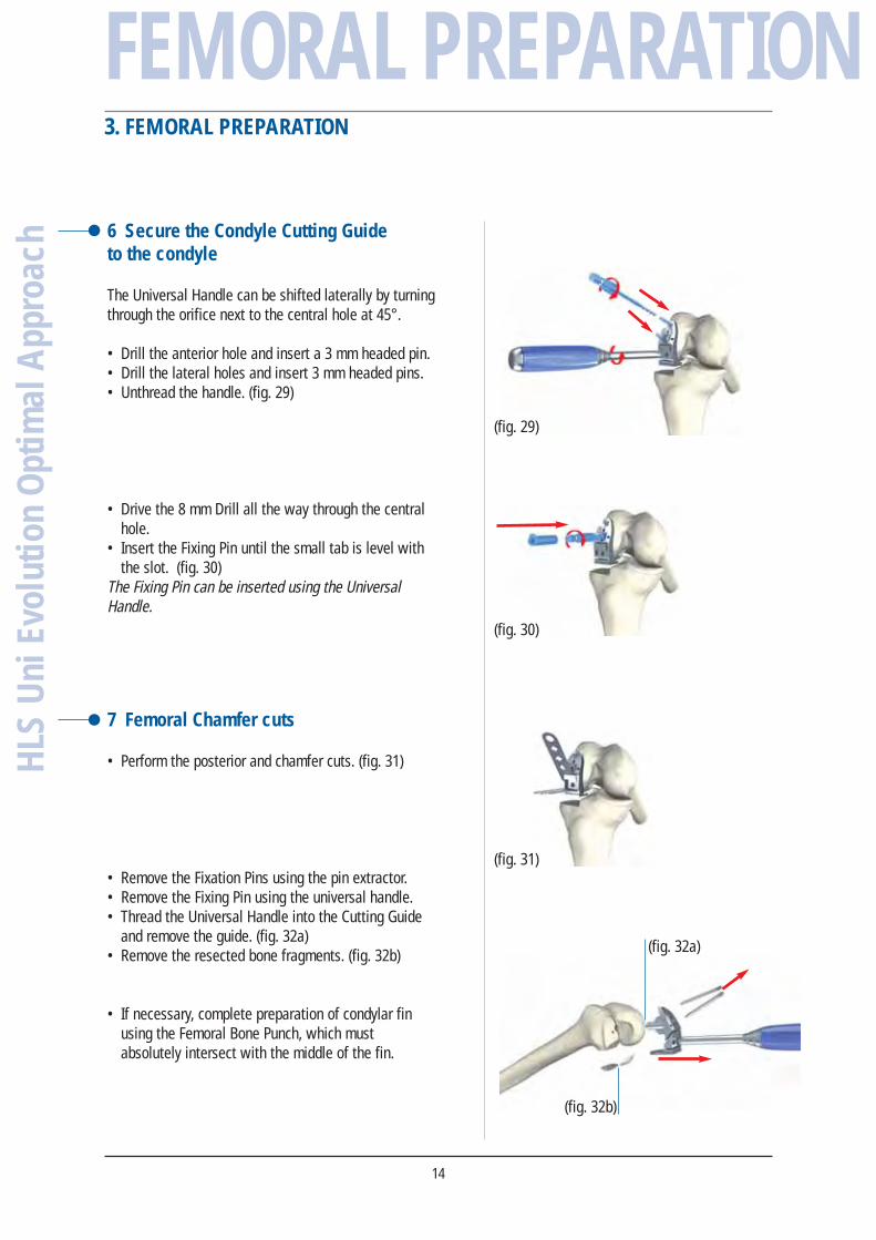
ach 6 Secure the Condyle Cutting Guide
to the condyle
The Universal Handle can be shifted laterally by turningthrough the orifice next to the central hole at 45°.
• Drill the anterior hole and insert a 3 mm headed pin.• Drill the lateral holes and insert 3 mm headed pins.• Unthread the handle. (fig. 29)
• Drive the 8 mm Drill all the way through the centralhole.
• Insert the Fixing Pin until the small tab is level withthe slot. (fig. 30)
The Fixing Pin can be inserted using the UniversalHandle.
7 Femoral Chamfer cuts
• Perform the posterior and chamfer cuts. (fig. 31)
• Remove the Fixation Pins using the pin extractor.• Remove the Fixing Pin using the universal handle.• Thread the Universal Handle into the Cutting Guide
and remove the guide. (fig. 32a)• Remove the resected bone fragments. (fig. 32b)
• If necessary, complete preparation of condylar finusing the Femoral Bone Punch, which mustabsolutely intersect with the middle of the fin.
14
(fig. 29)
(fig. 30)
(fig. 31)
(fig. 32a)
(fig. 32b)
3. FEMORAL PREPARATION
FEMORAL PREPARATION

1 Trial components
• Insert the Trial Femoral Component using the TibialComponent Grasper. (fig. 33)
With the knee in deep flexion, check that there areno prominences or uncut bones posteriorly.Such residuals should be resected to avoidimpingement on PE and to increase flexion range.
• Insert the Trial Femoral Component using the FemoralImpactor and then the selected Trial Tibial Component.(fig. 34)
2 Static test in extension(fig. 35)
• The prosthetic condyle should rest flat on the TrialTibial Component, with no medial no lateral lift-off.
• A “safety laxity” should persist to ensure thereis no overcorrection.If this is not the case, additional bone must beremoved from the tibia, which will eliminatethe indentations from the fixation pins.
3 Dynamic test
The Trial Tibial Component must remain perfectly stableduring ROM assessment:• There should be no tilt effects in flexion, otherwise
the tibial slope must be readjusted.• There should be no antero-posterior translation,
as this indicates that the ligaments are too tightor the Trial Tibial Component is too thick.
15
(fig. 33)
(fig. 34)
(fig. 35)
4. TRIAL REDUCTION
HLS
Uni
Evo
lutio
n O
ptim
al A
ppro
ach
TRIAL REDUCTION

• Apply a thin layer of cement to the inner surfaces of the components.
With the knee flexed:
• Insert the Tibial Component and seat it using the Tibial Impactor. (fig. 37)
• Insert the Femoral Component and seat it using the Femoral Impactor. (fig. 38)
• Extend the knee and remove any excess cement.
HLS
Uni
Evo
lutio
n O
ptim
al A
ppro
ach
16
(fig. 38)
COMPONENTIMPLANTATION
(fig. 37)
5. COMPONENT IMPLANTATION

17
HLS
Uni
Evo
lutio
n O
ptim
al A
ppro
achFemoral instrument case
YKAG67
INSTRUMENTSINSTRUMENTS
Femoral Guide for Condyle PositionningMDU701
Femoral ImpactorMDU702
Universal HandleMDU703
Femoral Drill GuideMDU704
Condyle Cutting Guide LL/MR
T1 MDU711 T2 MDU712T3 MDU713T4 MDU714
Condyle Cutting Guide ML/LR
T1 MDU721 T2 MDU722T3 MDU723T4 MDU724
Femoral Bone PunchMDU705
Headed Pin, Ø 3 mmMDU706
Fixing PinMDU707

Fixation Pin, 3 x 40 mmMDU708
RaspMDU730
Drill Bit, Ø 8 mmMDU731
Drill Bit w/hub, Ø 3 mmMDU732
Flat Ended Drill, Ø 3 mmMDU742
Ø 3 mm L.75mm Cutting PinMDU907
Trial Femoral Component Extraction PinMDU518
Trial Femoral Component, Thick. 3 mm
T1 MDU531 T2 MDU532T3 MDU533T4 MDU534
Saw blades• ZimmerMDU503MDU556 (new design)
• Stryker BMDU555
• AesculapMDU506
• AO MüllerMDU507
HLS
Uni
Evo
lutio
n O
ptim
al A
ppro
ach
18
INSTRUMENTSINSTRUMENTS

19
HLS
Uni
Evo
lutio
n O
ptim
al A
ppro
ach
Patellar Retractor, ML/LRMDU709
Patellar Retractor, LL/MRMDU710
Tibial ImpactorMDU733
Alignement Jig for Tibial CutMDU734
Tibial Cutting Guide,LL/MRMDU735
Tibial Cutting Guide, ML/LRMDU736
Tibial instrument caseYKAG68
INSTRUMENTSINSTRUMENTS

HLS
Uni
Evo
lutio
n O
ptim
al A
ppro
ach
20
INSTRUMENTSINSTRUMENTS
Malleolar ClampMDU739
Fixation Pin, 3 x 110 mm MDU905
Flat Ended Drill Ø 3 mmMDU742
Ø 3 mm L. 75mm Cutting PinMDU907
Trial Tibial Components, MR/LL
#1T 9 mm MDU112 T 11 mm MDU114T 13 mm MDU116
#2T 9 mm MDU122T 11 mm MDU124T 13 mm MDU126
#3T 9 mm MDU132T 11 mm MDU134T 13 mm MDU136
#4T 9 mm MDU142T 11 mm MDU144T 13 mm MDU146
#5T 9 mm MDU152T 11 mm MDU154T 13 mm MDU156
Trial Tibial Components, ML/LR
#1T 9 mm MDU212T 11 mm MDU214T 13 mm MDU216
#2T 9 mm MDU222T 11 mm MDU224T 13 mm MDU226
#3T 9 mm MDU232T 11 mm MDU234T 13 mm MDU236
#4T 9 mm MDU242T 11 mm MDU244T 13 mm MDU246
#5T 9 mm MDU252T 11 mm MDU254T 13 mm MDU256

21
HLS
Uni
Evo
lutio
n O
ptim
al A
ppro
achTibial Component
GrasperMDU919
Pin PullerMVV062
OsteotomeMDU500
Joint Line Probe PinMDU501
Pin PunchMDU511
Optional instruments
Tibial Cutting Guide, LL/MRMDU738
Tibial Cutting Guide, ML/LRMDU737
Ankle “V”MDU740
V-Shaped Device for EM Alignment GuideMDU741
INSTRUMENTSINSTRUMENTS

NOTES
NOTESH
LS U
ni E
volu
tion
Opt
imal
App
roac
h
22

23
HLS
Uni
Evo
lutio
n O
ptim
al A
ppro
ach
NOTES
NOTES
HLS
Uni
Evo
lutio
n O
ptim
al A
ppro
ach
IMPLANTS
IMPLANTS
UGUT
07.1
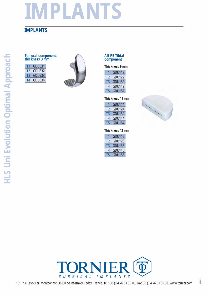
Femoral component, thickness 3 mm
T1 GDU531 T2 GDU532T3 GDU533T4 GDU534
All-PE Tibial component
Thickness 9 mm
T1 GDU112T2 GDU122T3 GDU132T4 GDU142T5 GDU152
Thickness 11 mm
T1 GDU114T2 GDU124T3 GDU134T4 GDU144T5 GDU154
Thickness 13 mm
T1 GDU116T2 GDU126T3 GDU136T4 GDU146T5 GDU156
161, rue Lavoisier. Montbonnot. 38334 Saint-Ismier Cedex. France. Tel.: 33 (0)4 76 61 35 00. Fax: 33 (0)4 76 61 35 33. www.tornier.com