Embed Size (px)
Citation preview
Surgical Technique

Nota Bene
The technique description herein is made available to the healthcare professional toillustrate the author’s suggested treatment for the uncomplicated procedure. In the finalanalysis, the preferred treatment is that which addresses the needs of the specific patient.
ContentsDesign rationale ........................................................3
Indications ................................................................3
Design features ........................................................4
Design specifications ................................................5
Surgical Technique ....................................................6
Catalog information ..................................................19
TRIGEN™Hindfoot Fusion NailSurgical Technique
As described by:Thomas A. Russell, MDRoy W. Sanders, MDJohn S. Early, MD
2
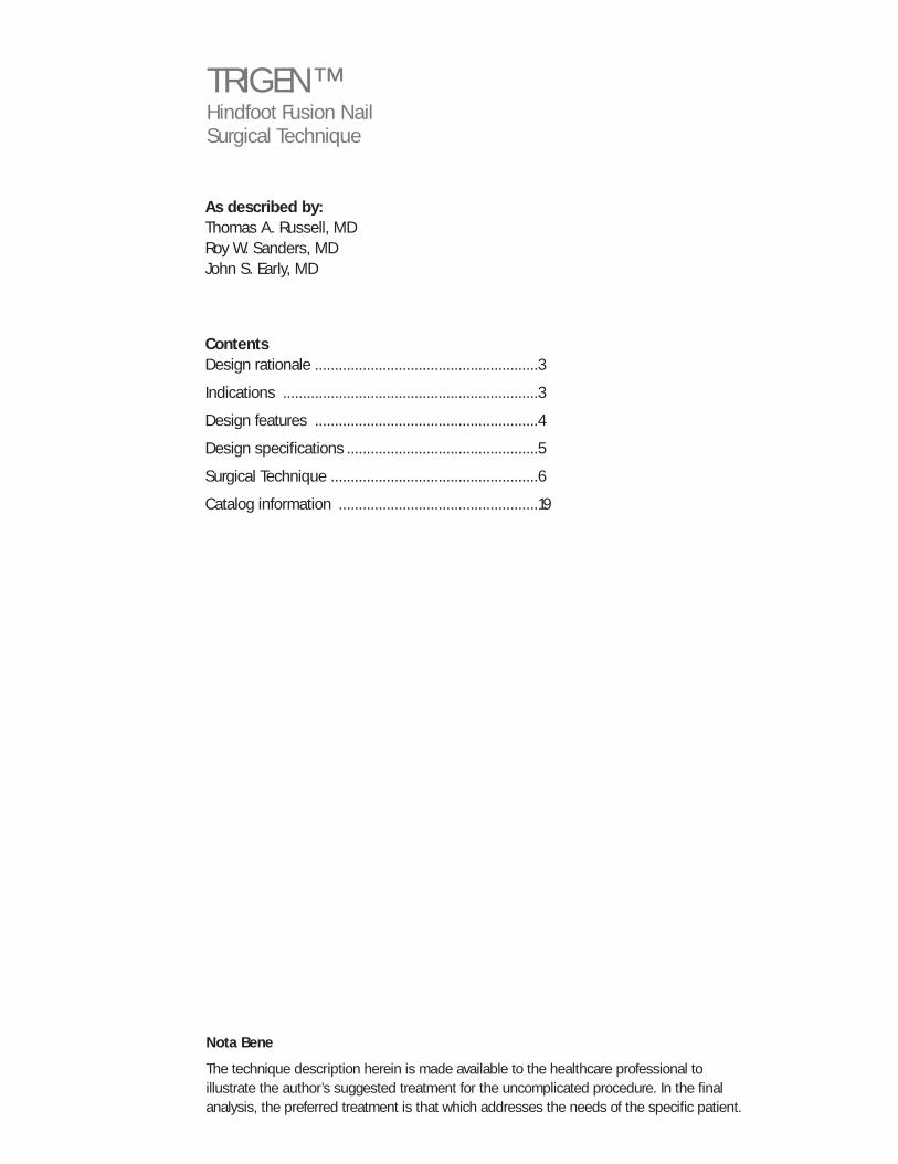
Uncover an easier and moreadvanced nailing system
The TRIGEN™ Hindfoot Fusion Nail (HFN) offers unique lockingconfigurations allowing the surgeon to target the best bonepossible within the hindfoot to maximize purchase and position. Asan addition to the already successful TRIGEN Intramedullary NailSystem, the TRIGEN HFN uses the simplified instrumentation thathas made TRIGEN a standout among other systems.
Design rationale
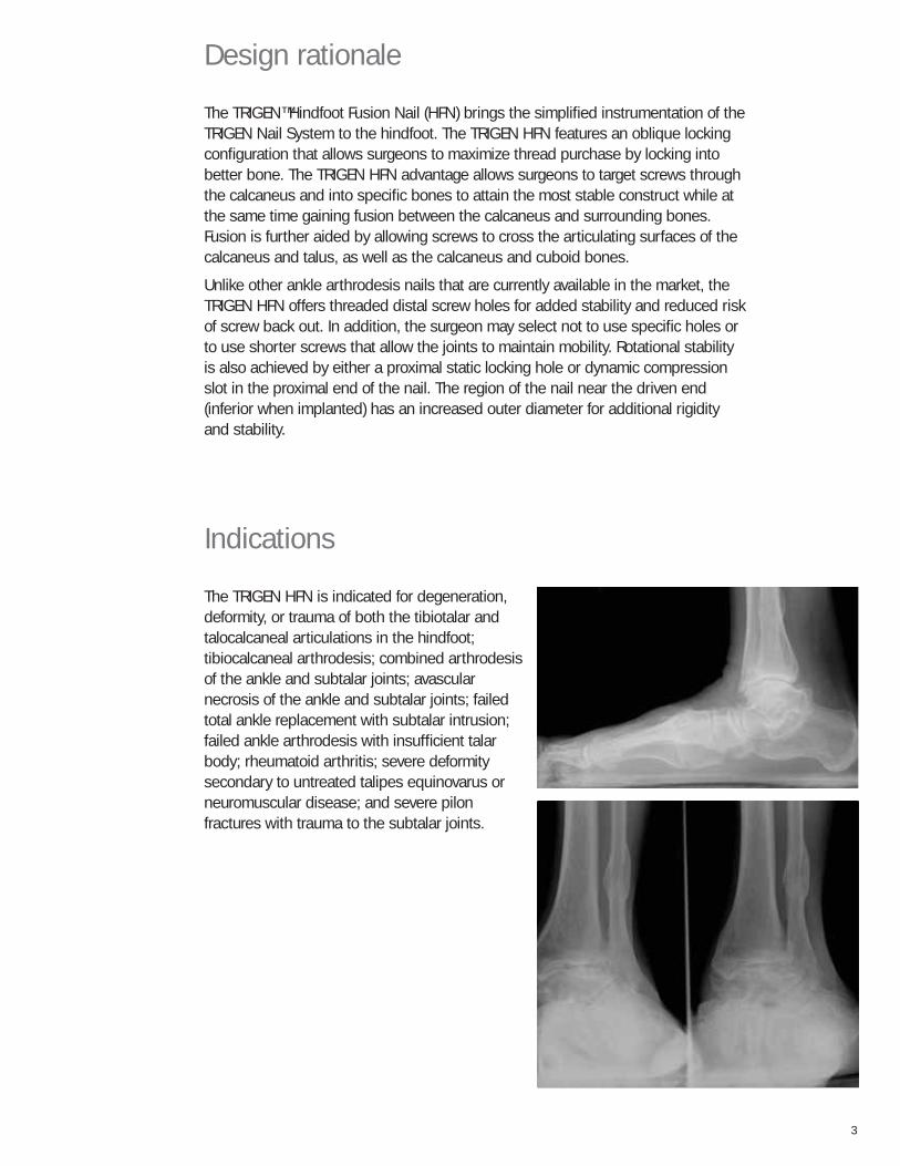
The TRIGEN™ Hindfoot Fusion Nail (HFN) brings the simplified instrumentation of theTRIGEN Nail System to the hindfoot. The TRIGEN HFN features an oblique lockingconfiguration that allows surgeons to maximize thread purchase by locking intobetter bone. The TRIGEN HFN advantage allows surgeons to target screws throughthe calcaneus and into specific bones to attain the most stable construct while atthe same time gaining fusion between the calcaneus and surrounding bones.Fusion is further aided by allowing screws to cross the articulating surfaces of thecalcaneus and talus, as well as the calcaneus and cuboid bones.
Unlike other ankle arthrodesis nails that are currently available in the market, theTRIGEN HFN offers threaded distal screw holes for added stability and reduced riskof screw back out. In addition, the surgeon may select not to use specific holes orto use shorter screws that allow the joints to maintain mobility. Rotational stabilityis also achieved by either a proximal static locking hole or dynamic compressionslot in the proximal end of the nail. The region of the nail near the driven end(inferior when implanted) has an increased outer diameter for additional rigidityand stability.
3
Indications
The TRIGEN HFN is indicated for degeneration,deformity, or trauma of both the tibiotalar andtalocalcaneal articulations in the hindfoot;tibiocalcaneal arthrodesis; combined arthrodesisof the ankle and subtalar joints; avascularnecrosis of the ankle and subtalar joints; failedtotal ankle replacement with subtalar intrusion;failed ankle arthrodesis with insufficient talarbody; rheumatoid arthritis; severe deformitysecondary to untreated talipes equinovarus orneuromuscular disease; and severe pilonfractures with trauma to the subtalar joints.
4
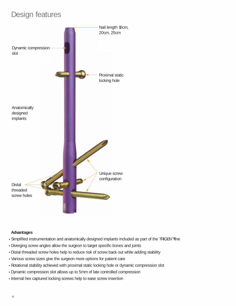
Design features
Dynamic compressionslot
Distalthreadedscrew holes
Proximal staticlocking hole
Nail length 16cm, 20cm, 25cm
Anatomicallydesignedimplants
Unique screwconfiguration
Advantages
• Simplified instrumentation and anatomically designed implants included as part of the TRIGEN™ line
• Diverging screw angles allow the surgeon to target specific bones and joints
• Distal threaded screw holes help to reduce risk of screw back out while adding stability
• Various screw sizes give the surgeon more options for patient care
• Rotational stability achieved with proximal static locking hole or dynamic compression slot
• Dynamic compression slot allows up to 5mm of late controlled compression
• Internal hex captured locking screws help to ease screw insertion
55
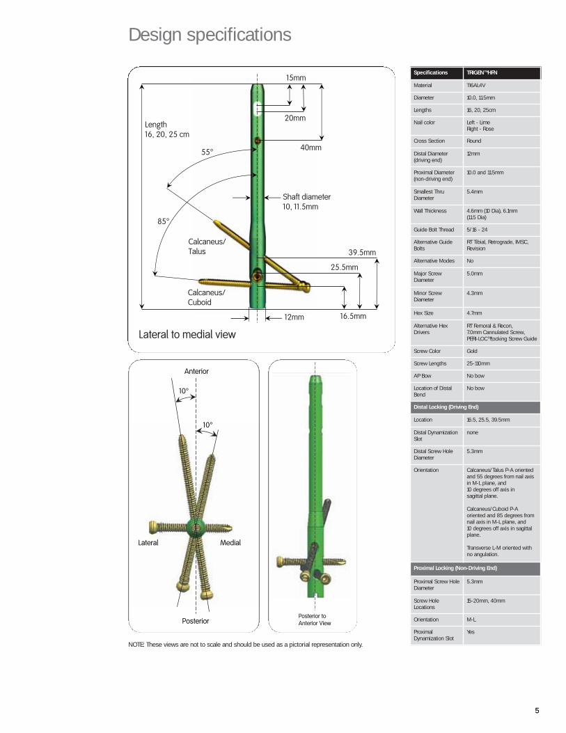
Design specifications
Length 16, 20, 25 cm
Calcaneus/ Cuboid
Calcaneus/ Talus
55°
85°
Shaft diameter10, 11.5mm
12mm
15mm
20mm
40mm
Lateral to medial view
39.5mm
25.5mm
16.5mm
Specifications TRIGEN™ HFN
Material TI6AL4V
Diameter 10.0, 11.5mm
Lengths 16, 20, 25cm
Nail color Left - LimeRight - Rose
Cross Section Round
Distal Diameter(driving end)
12mm
Proximal Diameter(non-driving end)
10.0 and 11.5mm
Smallest ThruDiameter
5.4mm
Wall Thickness 4.6mm (10 Dia), 6.1mm (11.5 Dia)
Guide Bolt Thread 5/16 - 24
Alternative GuideBolts
RT Tibial, Retrograde, IMSC,Revision
Alternative Modes No
Major ScrewDiameter
5.0mm
Minor ScrewDiameter
4.3mm
Hex Size 4.7mm
Alternative HexDrivers
RT Femoral & Recon,7.0mm Cannulated Screw,PERI-LOC™ Locking Screw Guide
Screw Color Gold
Screw Lengths 25-110mm
AP Bow No bow
Location of DistalBend
No bow
Distal Locking (Driving End)
Location 16.5, 25.5, 39.5mm
Distal DynamizationSlot
none
Distal Screw HoleDiameter
5.3mm
Orientation Calcaneus/Talus P-A orientedand 55 degrees from nail axisin M-L plane, and10 degrees off axis in sagittal plane.
Calcaneus/Cuboid P-Aoriented and 85 degrees fromnail axis in M-L plane, and10 degrees off axis in sagittalplane.
Transverse L-M oriented withno angulation.
Proximal Locking (Non-Driving End)
Proximal Screw HoleDiameter
5.3mm
Screw HoleLocations
15-20mm, 40mm
Orientation M-L
ProximalDynamization Slot
Yes
Anterior
Posterior
Lateral Medial
10°
10°
NOTE: These views are not to scale and should be used as a pictorial representation only.
Posterior to Anterior View
6
™Trademark of Smith & Nephew, Reg. US Pat. & Tm. Off.
OrthopaedicsSmith & Nephew, Inc.1450 East Brooks RoadMemphis, TN 38116, USA(901) 396-2121
For information: 1-800-821-5700For orders and order inquiries: 1-800-238-7538www.smithnephew.com
LEFTRIGHT
LATERAL VIEWA-P VIEW
Internal Hex Nail Cap
Size 0
20 mm
10 mm15 mm
5 mm
5.0 mm Cortical Screw
10 mm
20 mm
30 mm
Top of Nail
Drill Guide
mm
0
10
20
30
40
50
60
70
80
90
100
110
120
130
140
150
11.5 mm
10 mm
117% Magnification
mm mm
30
40
50
60
70
80
90
100
110
25
35
45
55
65
75
85
95
105
20
15
10
5
0
cm
12 mmProximal diameter
* 25 cm
20 cm
16 cm
* Special Request
02/05 71180961
Template
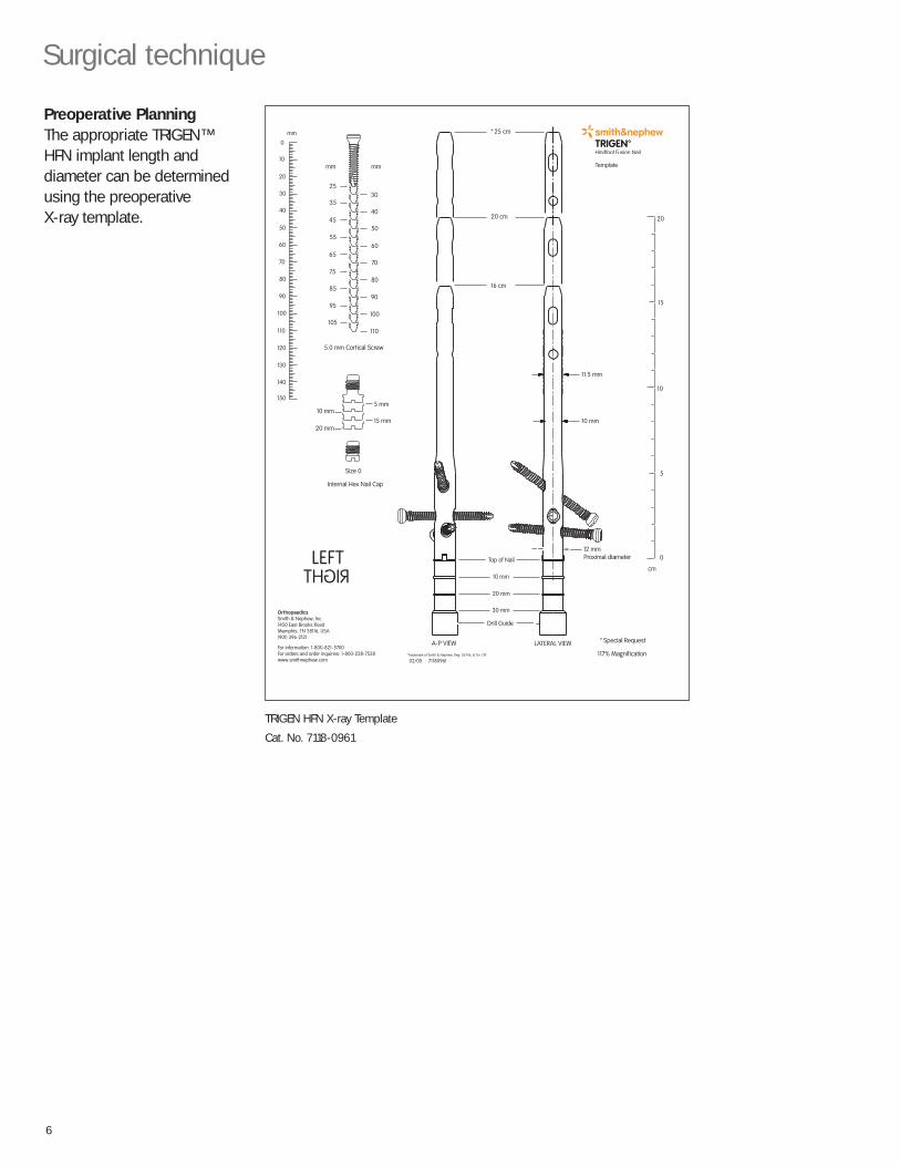
Surgical technique
Preoperative PlanningThe appropriate TRIGEN™HFN implant length anddiameter can be determinedusing the preoperative X-ray template.
TRIGEN HFN X-ray Template
Cat. No. 7118-0961
77
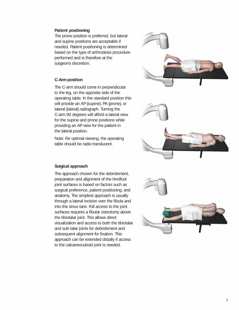
Patient positioningThe prone position is preferred, but lateraland supine positions are acceptable ifneeded. Patient positioning is determinedbased on the type of arthrodesis procedureperformed and is therefore at the surgeon’s discretion.
C-Arm position
The C-arm should come in perpendicular to the leg, on the opposite side of the operating table. In the standard position thiswill provide an AP (supine), PA (prone), orlateral (lateral) radiograph. Turning the C-arm 90 degrees will afford a lateral view for the supine and prone positions while providing an AP view for the patient in the lateral position.
Note: For optimal viewing, the operating table should be radio translucent.
Surgical approach
The approach chosen for the debridement,preparation and alignment of the hindfootjoint surfaces is based on factors such assurgical preference, patient positioning, andanatomy. The simplest approach is usuallythrough a lateral incision over the fibula andinto the sinus tarsi. Full access to the jointsurfaces requires a fibular osteotomy abovethe tibiotalar joint. This allows directvisualization and access to both the tibiotalarand sub-talar joints for debridement andsubsequent alignment for fixation. Thisapproach can be extended distally if accessto the calcaneocuboid joint is needed.
8
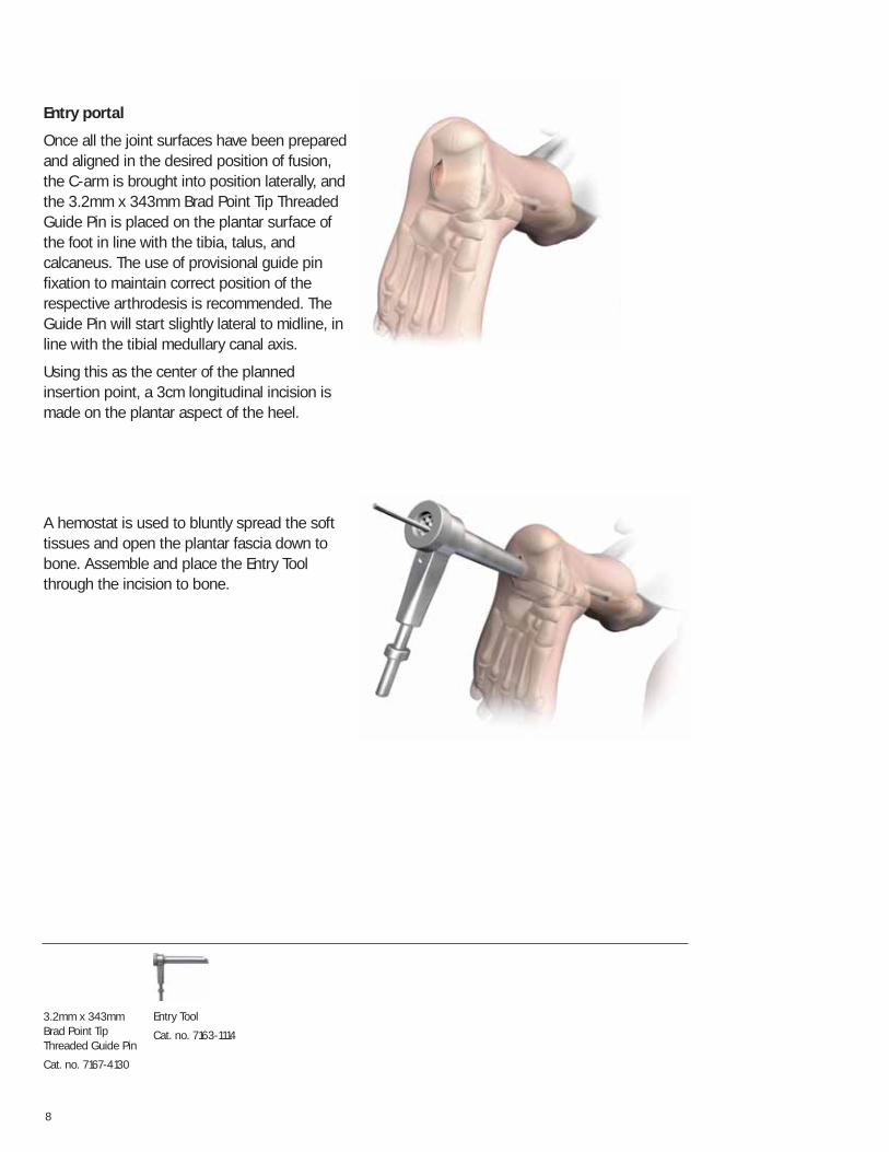
Entry portal
Once all the joint surfaces have been preparedand aligned in the desired position of fusion,the C-arm is brought into position laterally, andthe 3.2mm x 343mm Brad Point Tip ThreadedGuide Pin is placed on the plantar surface ofthe foot in line with the tibia, talus, andcalcaneus. The use of provisional guide pinfixation to maintain correct position of therespective arthrodesis is recommended. TheGuide Pin will start slightly lateral to midline, inline with the tibial medullary canal axis.
Using this as the center of the plannedinsertion point, a 3cm longitudinal incision ismade on the plantar aspect of the heel.
A hemostat is used to bluntly spread the softtissues and open the plantar fascia down tobone. Assemble and place the Entry Toolthrough the incision to bone.
3.2mm x 343mmBrad Point TipThreaded Guide Pin
Cat. no. 7167-4130
Entry Tool
Cat. no. 7163-1114
9
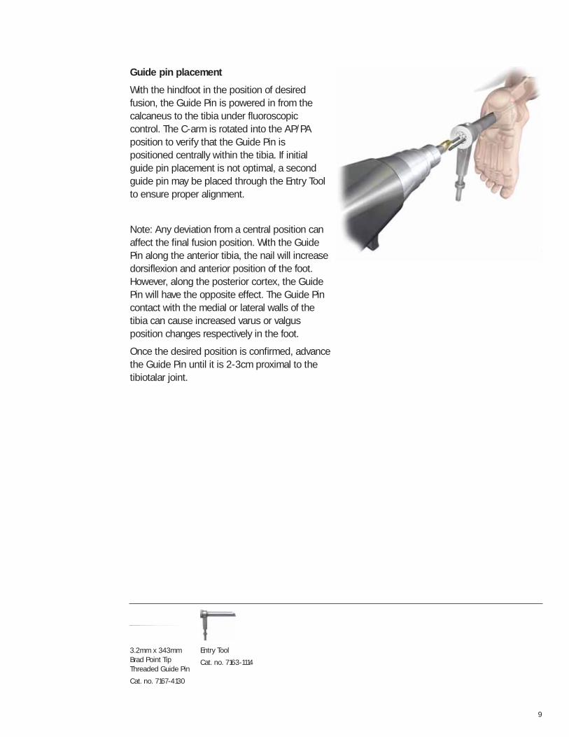
Guide pin placement
With the hindfoot in the position of desiredfusion, the Guide Pin is powered in from thecalcaneus to the tibia under fluoroscopic control. The C-arm is rotated into the AP/PAposition to verify that the Guide Pin ispositioned centrally within the tibia. If initialguide pin placement is not optimal, a secondguide pin may be placed through the Entry Toolto ensure proper alignment.
Note: Any deviation from a central position canaffect the final fusion position. With the GuidePin along the anterior tibia, the nail will increasedorsiflexion and anterior position of the foot.However, along the posterior cortex, the GuidePin will have the opposite effect. The Guide Pincontact with the medial or lateral walls of thetibia can cause increased varus or valgusposition changes respectively in the foot.
Once the desired position is confirmed, advancethe Guide Pin until it is 2-3cm proximal to thetibiotalar joint.
3.2mm x 343mmBrad Point TipThreaded Guide Pin
Cat. no. 7167-4130
Entry Tool
Cat. no. 7163-1114
10
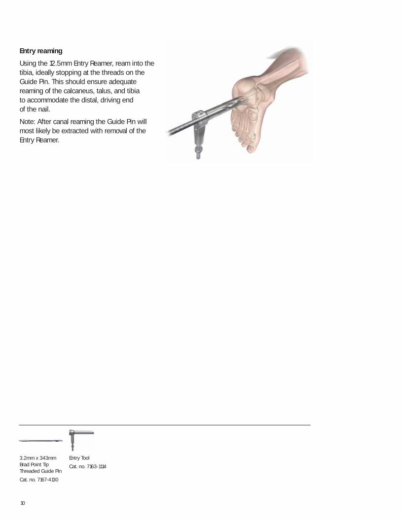
Entry reaming
Using the 12.5mm Entry Reamer, ream into thetibia, ideally stopping at the threads on theGuide Pin. This should ensure adequatereaming of the calcaneus, talus, and tibia to accommodate the distal, driving end of the nail.
Note: After canal reaming the Guide Pin willmost likely be extracted with removal of theEntry Reamer.
3.2mm x 343mmBrad Point TipThreaded Guide Pin
Cat. no. 7167-4130
Entry Tool
Cat. no. 7163-1114
11
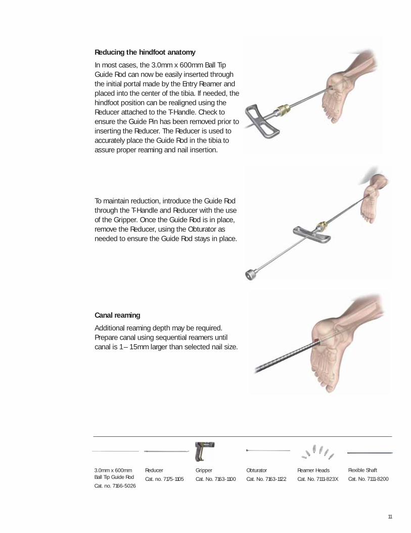
Reducing the hindfoot anatomy
In most cases, the 3.0mm x 600mm Ball TipGuide Rod can now be easily inserted throughthe initial portal made by the Entry Reamer andplaced into the center of the tibia. If needed, thehindfoot position can be realigned using theReducer attached to the T-Handle. Check toensure the Guide Pin has been removed prior toinserting the Reducer. The Reducer is used toaccurately place the Guide Rod in the tibia toassure proper reaming and nail insertion.
To maintain reduction, introduce the Guide Rodthrough the T-Handle and Reducer with the useof the Gripper. Once the Guide Rod is in place,remove the Reducer, using the Obturator asneeded to ensure the Guide Rod stays in place.
Canal reaming
Additional reaming depth may be required.Prepare canal using sequential reamers untilcanal is 1 – 1.5mm larger than selected nail size.
3.0mm x 600mmBall Tip Guide Rod
Cat. no. 7166-5026
Reducer
Cat. no. 7175-1105
Reamer Heads
Cat. No. 7111-823X
Gripper
Cat. No. 7163-1100
Obturator
Cat. No. 7163-1122
Flexible Shaft
Cat. No. 7111-8200
12
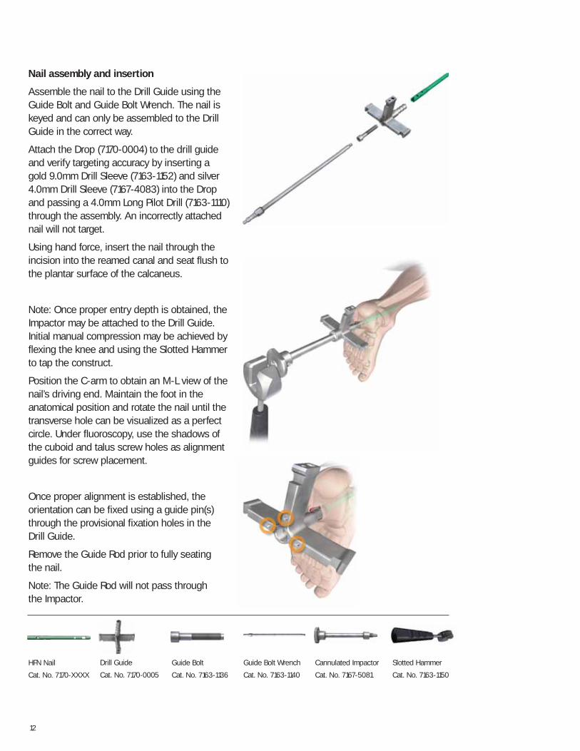
Nail assembly and insertion
Assemble the nail to the Drill Guide using theGuide Bolt and Guide Bolt Wrench. The nail iskeyed and can only be assembled to the DrillGuide in the correct way.
Attach the Drop (7170-0004) to the drill guide and verify targeting accuracy by inserting a gold 9.0mm Drill Sleeve (7163-1152) and silver4.0mm Drill Sleeve (7167-4083) into the Dropand passing a 4.0mm Long Pilot Drill (7163-1110)through the assembly. An incorrectly attachednail will not target.
Using hand force, insert the nail through theincision into the reamed canal and seat flush tothe plantar surface of the calcaneus.
Note: Once proper entry depth is obtained, theImpactor may be attached to the Drill Guide.Initial manual compression may be achieved byflexing the knee and using the Slotted Hammerto tap the construct.
Position the C-arm to obtain an M-L view of thenail’s driving end. Maintain the foot in theanatomical position and rotate the nail until thetransverse hole can be visualized as a perfectcircle. Under fluoroscopy, use the shadows ofthe cuboid and talus screw holes as alignmentguides for screw placement.
Once proper alignment is established, theorientation can be fixed using a guide pin(s)through the provisional fixation holes in the Drill Guide.
Remove the Guide Rod prior to fully seating the nail.
Note: The Guide Rod will not pass through the Impactor.
HFN Nail
Cat. No. 7170-XXXX
Drill Guide
Cat. No. 7170-0005
Guide Bolt
Cat. No. 7163-1136
Guide Bolt Wrench
Cat. No. 7163-1140
Cannulated Impactor
Cat. No. 7167-5081
Slotted Hammer
Cat. No. 7163-1150
13
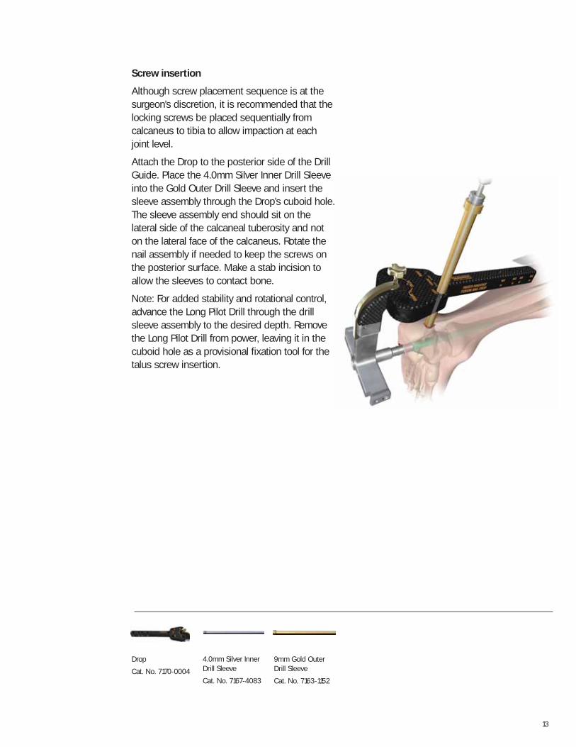
Screw insertion
Although screw placement sequence is at thesurgeon’s discretion, it is recommended that thelocking screws be placed sequentially fromcalcaneus to tibia to allow impaction at eachjoint level.
Attach the Drop to the posterior side of the DrillGuide. Place the 4.0mm Silver Inner Drill Sleeveinto the Gold Outer Drill Sleeve and insert thesleeve assembly through the Drop’s cuboid hole.The sleeve assembly end should sit on thelateral side of the calcaneal tuberosity and noton the lateral face of the calcaneus. Rotate thenail assembly if needed to keep the screws onthe posterior surface. Make a stab incision toallow the sleeves to contact bone.
Note: For added stability and rotational control,advance the Long Pilot Drill through the drillsleeve assembly to the desired depth. Removethe Long Pilot Drill from power, leaving it in thecuboid hole as a provisional fixation tool for thetalus screw insertion.
Drop
Cat. No. 7170-0004
4.0mm Silver InnerDrill Sleeve
Cat. No. 7167-4083
9mm Gold OuterDrill Sleeve
Cat. No. 7163-1152
14
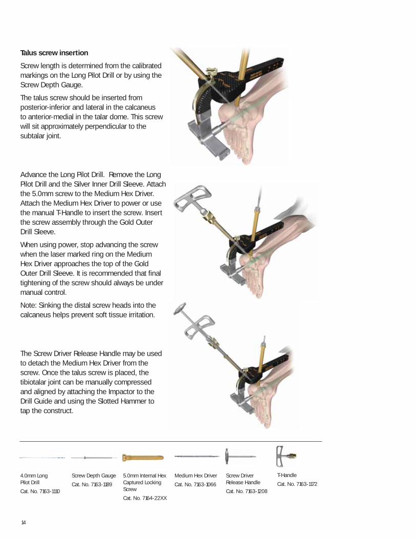
Talus screw insertion
Screw length is determined from the calibratedmarkings on the Long Pilot Drill or by using theScrew Depth Gauge.
The talus screw should be inserted fromposterior-inferior and lateral in the calcaneus to anterior-medial in the talar dome. This screwwill sit approximately perpendicular to thesubtalar joint.
Advance the Long Pilot Drill. Remove the LongPilot Drill and the Silver Inner Drill Sleeve. Attachthe 5.0mm screw to the Medium Hex Driver.Attach the Medium Hex Driver to power or usethe manual T-Handle to insert the screw. Insertthe screw assembly through the Gold Outer Drill Sleeve.
When using power, stop advancing the screwwhen the laser marked ring on the Medium Hex Driver approaches the top of the GoldOuter Drill Sleeve. It is recommended that finaltightening of the screw should always be undermanual control.
Note: Sinking the distal screw heads into thecalcaneus helps prevent soft tissue irritation.
The Screw Driver Release Handle may be usedto detach the Medium Hex Driver from thescrew. Once the talus screw is placed, thetibiotalar joint can be manually compressed and aligned by attaching the Impactor to theDrill Guide and using the Slotted Hammer to tap the construct.
4.0mm Long Pilot Drill
Cat. No. 7163-1110
Screw Depth Gauge
Cat. No. 7163-1189
5.0mm Internal HexCaptured LockingScrew
Cat. No. 7164-22XX
Medium Hex Driver
Cat. No. 7163-1066
Screw DriverRelease Handle
Cat. No. 7163-1208
T-Handle
Cat. No. 7163-1172
15
Cuboid screw insertion
Repeat this procedure for the cuboid screwwhich should be oriented posterior-medial in thecalcaneus to anterior-lateral in the cuboid.
Advance the Long Pilot Drill through to theanterior process of the calcaneus. If cuboidfixation is desired, continue advancing the Long Pilot Drill through to the distal aspect ofthe cuboid.
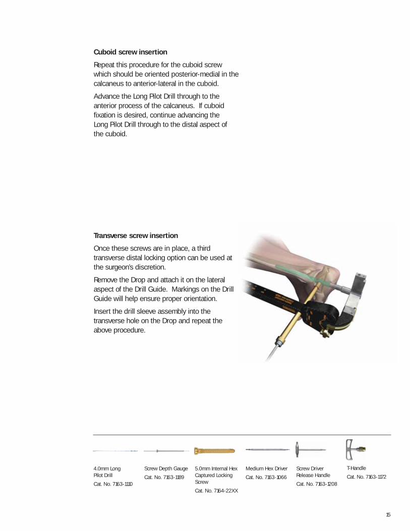
Transverse screw insertion
Once these screws are in place, a thirdtransverse distal locking option can be used atthe surgeon’s discretion.
Remove the Drop and attach it on the lateralaspect of the Drill Guide. Markings on the DrillGuide will help ensure proper orientation.
Insert the drill sleeve assembly into thetransverse hole on the Drop and repeat theabove procedure.
4.0mm Long Pilot Drill
Cat. No. 7163-1110
Screw Depth Gauge
Cat. No. 7163-1189
5.0mm Internal HexCaptured LockingScrew
Cat. No. 7164-22XX
Medium Hex Driver
Cat. No. 7163-1066
Screw DriverRelease Handle
Cat. No. 7163-1208
T-Handle
Cat. No. 7163-1172
16
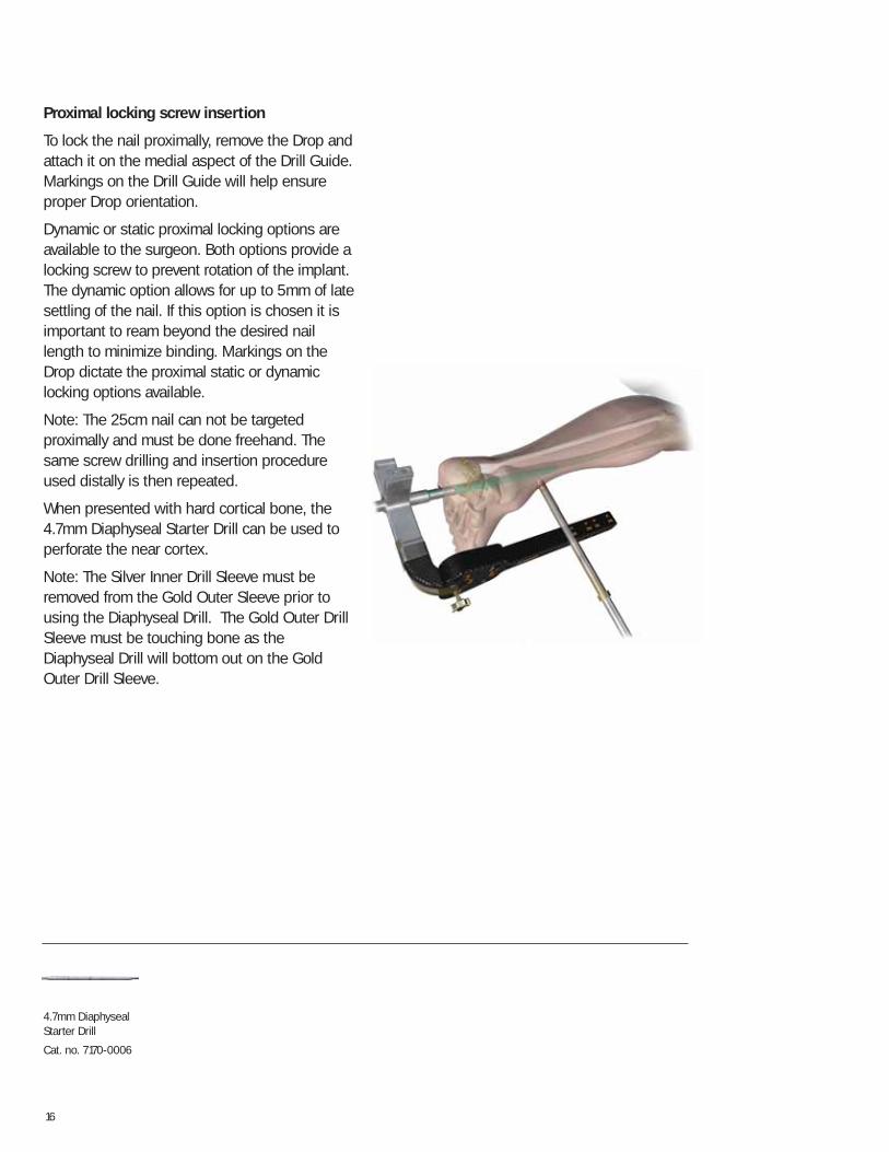
Proximal locking screw insertion
To lock the nail proximally, remove the Drop andattach it on the medial aspect of the Drill Guide.Markings on the Drill Guide will help ensureproper Drop orientation.
Dynamic or static proximal locking options areavailable to the surgeon. Both options provide alocking screw to prevent rotation of the implant.The dynamic option allows for up to 5mm of latesettling of the nail. If this option is chosen it isimportant to ream beyond the desired naillength to minimize binding. Markings on theDrop dictate the proximal static or dynamiclocking options available.
Note: The 25cm nail can not be targetedproximally and must be done freehand. Thesame screw drilling and insertion procedureused distally is then repeated.
When presented with hard cortical bone, the 4.7mm Diaphyseal Starter Drill can be used toperforate the near cortex.
Note: The Silver Inner Drill Sleeve must beremoved from the Gold Outer Sleeve prior tousing the Diaphyseal Drill. The Gold Outer DrillSleeve must be touching bone as theDiaphyseal Drill will bottom out on the GoldOuter Drill Sleeve.
4.7mm DiaphysealStarter Drill
Cat. no. 7170-0006
17
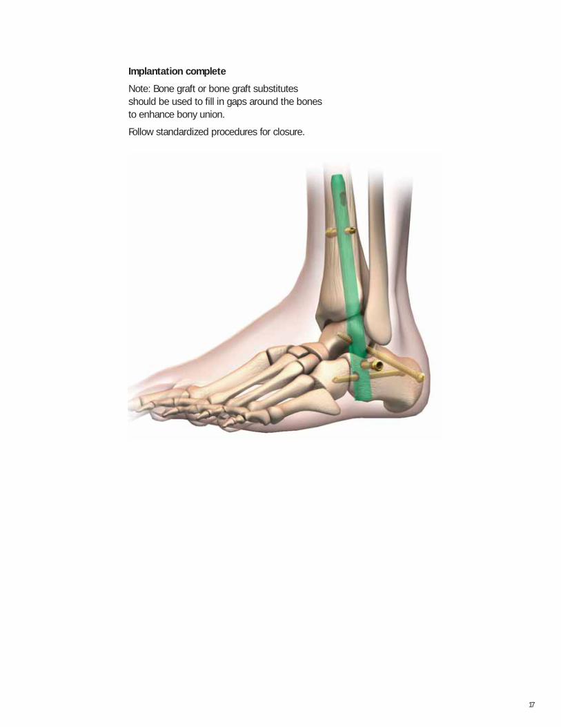
Implantation complete
Note: Bone graft or bone graft substitutesshould be used to fill in gaps around the bonesto enhance bony union.
Follow standardized procedures for closure.
18
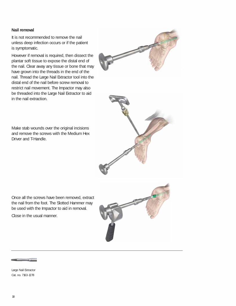
Nail removal
It is not recommended to remove the nail unless deep infection occurs or if the patient is symptomatic.
However if removal is required, then dissect theplantar soft tissue to expose the distal end ofthe nail. Clear away any tissue or bone that mayhave grown into the threads in the end of thenail. Thread the Large Nail Extractor tool into thedistal end of the nail before screw removal torestrict nail movement. The Impactor may alsobe threaded into the Large Nail Extractor to aidin the nail extraction.
Make stab wounds over the original incisionsand remove the screws with the Medium HexDriver and T-Handle.
Once all the screws have been removed, extractthe nail from the foot. The Slotted Hammer maybe used with the Impactor to aid in removal.
Close in the usual manner.
Large Nail Extractor
Cat. no. 7163-1278
19
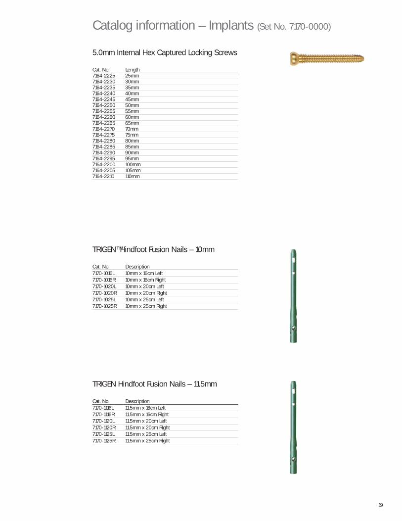
5.0mm Internal Hex Captured Locking Screws
Cat. No. Length7164-2225 25mm7164-2230 30mm7164-2235 35mm7164-2240 40mm7164-2245 45mm7164-2250 50mm7164-2255 55mm7164-2260 60mm7164-2265 65mm7164-2270 70mm7164-2275 75mm7164-2280 80mm7164-2285 85mm7164-2290 90mm7164-2295 95mm7164-2200 100mm7164-2205 105mm7164-2210 110mm
Catalog information – Implants (Set No. 7170-0000)
TRIGEN™ Hindfoot Fusion Nails – 10mm
Cat. No. Description7170-1016L 10mm x 16cm Left7170-1016R 10mm x 16cm Right7170-1020L 10mm x 20cm Left7170-1020R 10mm x 20cm Right7170-1025L 10mm x 25cm Left7170-1025R 10mm x 25cm Right
TRIGEN Hindfoot Fusion Nails – 11.5mm
Cat. No. Description7170-1116L 11.5mm x 16cm Left7170-1116R 11.5mm x 16cm Right7170-1120L 11.5mm x 20cm Left7170-1120R 11.5mm x 20cm Right7170-1125L 11.5mm x 25cm Left7170-1125R 11.5mm x 25cm Right
20
GripperCat. No. 7163-1100
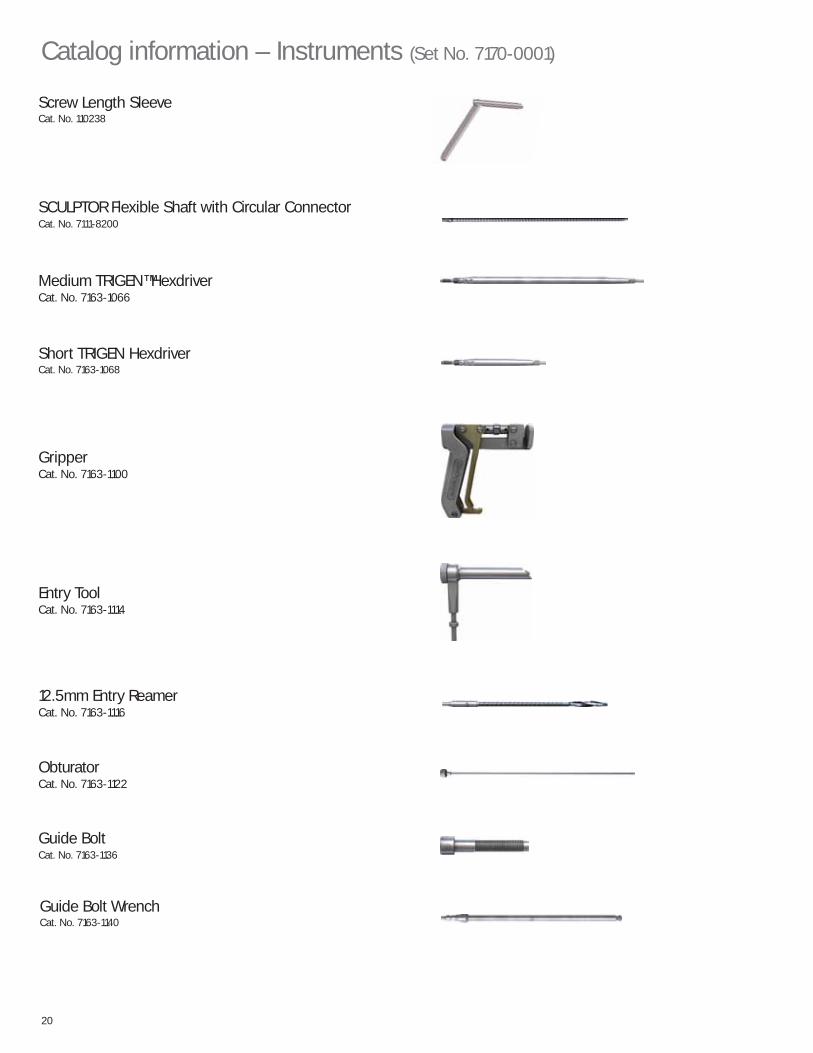
Short TRIGEN HexdriverCat. No. 7163-1068
Screw Length SleeveCat. No. 110238
SCULPTOR Flexible Shaft with Circular ConnectorCat. No. 7111-8200
Medium TRIGEN™ HexdriverCat. No. 7163-1066
Entry ToolCat. No. 7163-1114
12.5mm Entry ReamerCat. No. 7163-1116
ObturatorCat. No. 7163-1122
Catalog information – Instruments (Set No. 7170-0001)
Guide Bolt WrenchCat. No. 7163-1140
Guide BoltCat. No. 7163-1136
21
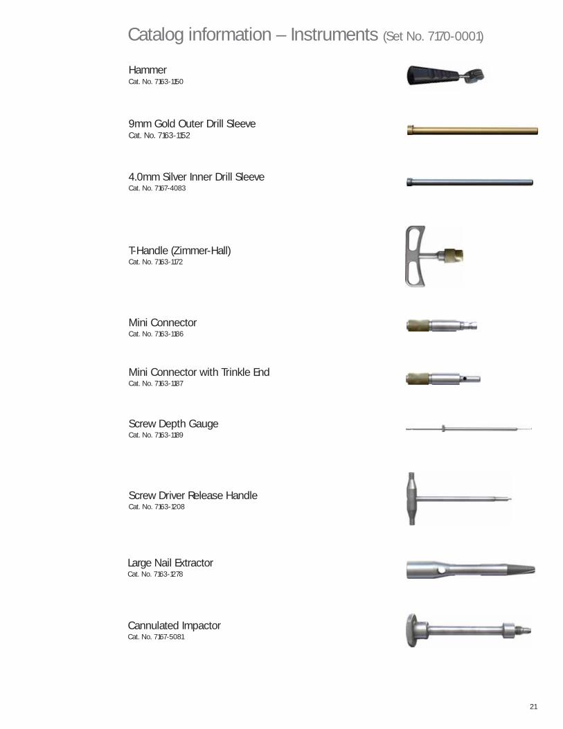
Large Nail ExtractorCat. No. 7163-1278
Cannulated ImpactorCat. No. 7167-5081
Catalog information – Instruments (Set No. 7170-0001)
9mm Gold Outer Drill SleeveCat. No. 7163-1152
Mini Connector with Trinkle EndCat. No. 7163-1187
Screw Driver Release HandleCat. No. 7163-1208
Screw Depth GaugeCat. No. 7163-1189
HammerCat. No. 7163-1150
T-Handle (Zimmer-Hall)Cat. No. 7163-1172
4.0mm Silver Inner Drill SleeveCat. No. 7167-4083
Mini ConnectorCat. No. 7163-1186
22
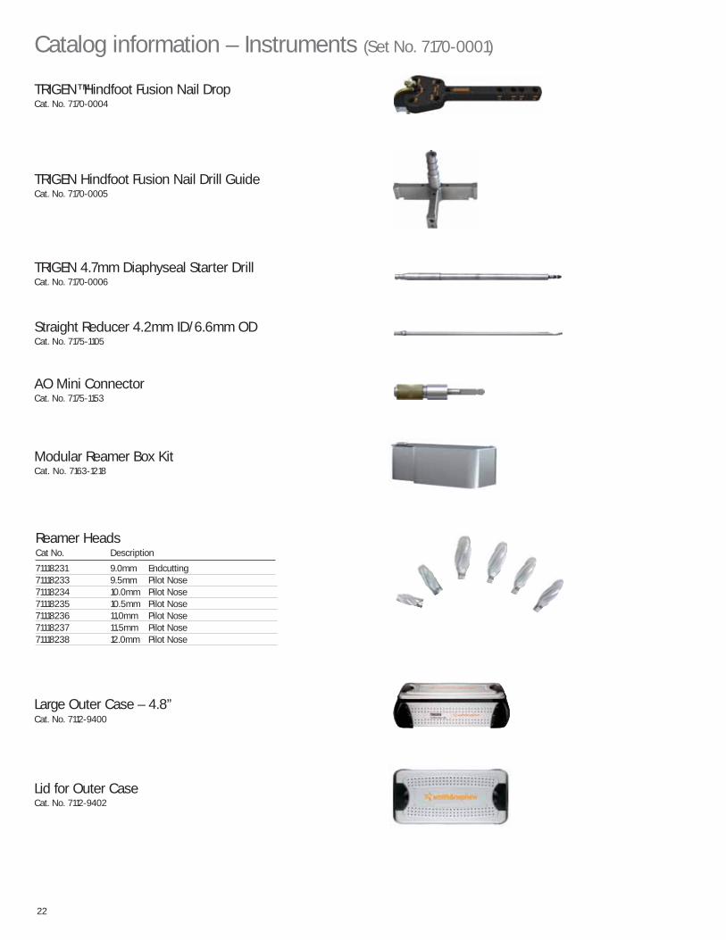
Reamer HeadsCat No. Description
71118231 9.0mm Endcutting71118233 9.5mm Pilot Nose71118234 10.0mm Pilot Nose71118235 10.5mm Pilot Nose71118236 11.0mm Pilot Nose71118237 11.5mm Pilot Nose71118238 12.0mm Pilot Nose
AO Mini ConnectorCat. No. 7175-1153
TRIGEN Hindfoot Fusion Nail Drill GuideCat. No. 7170-0005
TRIGEN 4.7mm Diaphyseal Starter DrillCat. No. 7170-0006
Straight Reducer 4.2mm ID/6.6mm ODCat. No. 7175-1105
TRIGEN™ Hindfoot Fusion Nail DropCat. No. 7170-0004
Catalog information – Instruments (Set No. 7170-0001)
Lid for Outer CaseCat. No. 7112-9402
Large Outer Case – 4.8”Cat. No. 7112-9400
Modular Reamer Box KitCat. No. 7163-1218
23
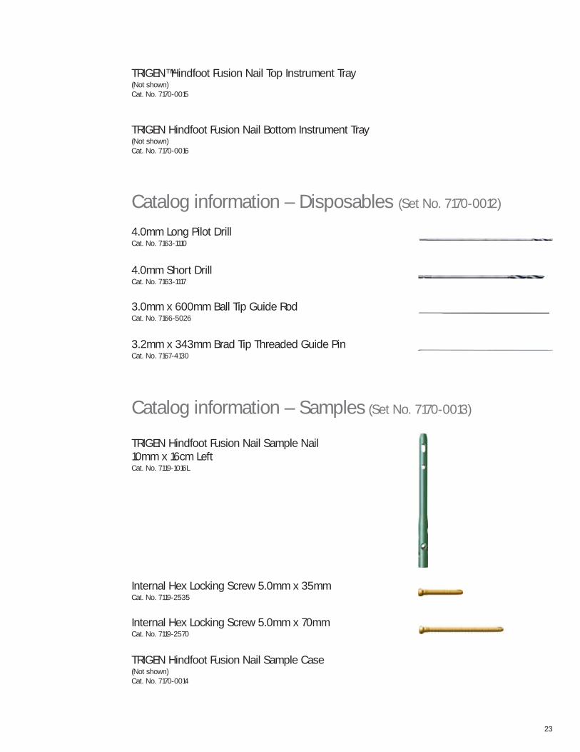
4.0mm Long Pilot DrillCat. No. 7163-1110
4.0mm Short DrillCat. No. 7163-1117
3.0mm x 600mm Ball Tip Guide RodCat. No. 7166-5026
3.2mm x 343mm Brad Tip Threaded Guide Pin Cat. No. 7167-4130
Catalog information – Disposables (Set No. 7170-0012)
Catalog information – Samples (Set No. 7170-0013)
TRIGEN Hindfoot Fusion Nail Sample Nail 10mm x 16cm LeftCat. No. 7119-1016L
Internal Hex Locking Screw 5.0mm x 35mmCat. No. 7119-2535
Internal Hex Locking Screw 5.0mm x 70mmCat. No. 7119-2570
TRIGEN Hindfoot Fusion Nail Sample Case(Not shown)Cat. No. 7170-0014
TRIGEN Hindfoot Fusion Nail Bottom Instrument Tray(Not shown)Cat. No. 7170-0016
TRIGEN™ Hindfoot Fusion Nail Top Instrument Tray(Not shown)Cat. No. 7170-0015

Notes


OrthopaedicsSmith & Nephew, Inc.1450 Brooks RoadMemphis, TN 38116USA
Telephone: 1-901-396-2121Information: 1-800-821-5700Orders/Inquiries: 1-800-238-7538
www.smith-nephew.com
™Trademark of Smith & Nephew. Reg. US Pat & TM Off. 7118-1028 REV0 09/10


![7163 BT Glide UG [7] · BT Glide – Edition 07 – 20.01.06 – 7163 • Stylish slide-design phone – slide the handset open to reveal the hidden keypad. • Large, full colour](https://img.pdfslide.net/doc/110x75/5f0b446b7e708231d42fabd1/7163-bt-glide-ug-7-bt-glide-a-edition-07-a-200106-a-7163-a-stylish-slide-design.jpg)