Embed Size (px)
Citation preview

SURVEY PRACTICE GUIDELINES FOR SUBDIVISIONS
WITHIN SPECIAL SURVEY AREAS
These guidelines are issued by the Land Surveyors Licensing Board of WA under regulation 26A of the Licensed Surveyors (Guidance of Surveyors) Regulations 1961. For the purposes of regulation 10 of the Transfer of Land (Surveys) Regulations 1995 the Registrar has approved the matters herein related to plans and the manner in which plans are prepared and presented. 1.0 INTRODUCTION - SPECIAL SURVEY AREAS
The Guidelines for Urban Subdivisions under Regulations 55A-55F of the Licensed Surveyors (Guidance of Surveyors) Regulations 1961 previously approved by the Board are repealed and substituted by these guidelines. These guidelines apply to all Crown and freehold subdivisions and survey-strata developments in rural, rural residential and town and suburban areas involving more than 10 serviced lots where roads are created. It is expected that these SSA procedures will be used in subdivisions anywhere where site works can be expected to destroy survey marks necessary for the accurate and reliable re-establishment of the new or original boundaries.
2.0 SURVEY SPECIFICATIONS AND STANDARDS
2.1 Connections to the Geodetic Network
Subdivision control networks must be connected to the State Geodetic Survey, using terrestrial or Global Positioning System (GPS) survey techniques. To constrain the survey and provide a redundancy, independent connections to two different Standard Survey Marks (SSMs) are essential. Any existing SSM used must be fully validated from its reference marks (RMs) prior to adoption. Those existing marks must be of at least the same ORDER as that being sought for the control survey being undertaken. For the purposes of providing connection to SSMs, only existing stations for which Landgate has published information can be used. The highest order of existing geodetic stations that are easily accessible and in the vicinity of the subdivision should be used.
The selected geodetic control stations should be at a spacing of less than 5km from the subdivision. If the existing geodetic network appears to be inadequate to control the subdivision, Manager Geodetic Survey at Landgate should be consulted.

In any case, connections should always be made to selected validated control points of adjacent networks whether carried out by the same or a different survey firm. This will prevent “edge matching” problems between successive developments/stages.
2.2 Re-establishment Survey
Any original boundaries comprising part of the surround of the subdivision must be comprehensively re-established before pre-calculating the plan. The re-establishment survey must be comprised of new measurements only. The only original values acceptable are those from a recent earlier stage of the same development carried out under these guidelines by the same survey firm. Where the residue land from a subdivision forms a very large balance lot the re-establishment may be confined to the area(s) being developed.
2.3 Accuracy
The method of survey and the accuracy of the measurements shall be such that there is less than a 1% probability that the actual error in the position of any mark with respect to any other mark will exceed K millimetres, where K = F √ 0.04 + S 2 where S is the direct distance between two points in kilometres, and F is as specified in the following table:
Mark to which the above tolerance applies
With respect to F
(a) Any temporary control mark (TCM) of the initial control and surround survey.
Any other TCM, any SSM, any control station on an adjacent subdivision.
60
(b) Any permanent control mark (PSM or PCM) and any cadastral reference mark or intersection spike (RM).
Any other PSM, PCM, RM, any SSM or TCM.
90
2.4 General Guidelines for Control Surveys
The Inter-Governmental Advisory Committee on Surveying and Mapping (ICSM) has published the Standards and Practices for Control Surveys (Special Publication 1 or SP1), the latest version of which can be downloaded from http://www.icsm.gov.au/icsm/publications/
guidelines for ssa's_v9.0_approved.doc Page 2 of 18

The recommended techniques and reduction practices outlined in SP1 to achieve a Class C control survey would be suitable to satisfy the control network accuracy required by these guidelines.
Horizontal survey control, once completed, must form a closed figure that is connected into a minimum of two existing geodetic stations. Least squares adjustments of the network, both minimally constrained and constrained by the connections into existing control must be carried out to verify the survey meets the required accuracy.
Control network observations may be by traditional terrestrial or GPS techniques or a combination of both. Observations may be made as indicated in guidelines 2.5 and 2.6 below, but with reference to the ICSM guidelines.
2.5 Control Survey by Traditional Terrestrial Survey Measurements
Generally EDM equipment and 1" theodolite, 5" digital theodolite or 3" total station should be used. Serial numbers of instruments should be submitted together with a calibration check of any EDM instrument used. Details can be documented in the control field book.
2.6 Control Surveys Using GPS
2.6.1 Limitations
These guidelines are specific to using the Global Positioning System (GPS) for survey control within Special Survey Areas. This imposes the following understanding and limitations.
• All ancillary equipment is in good adjustment and repair
and operated competently. This is of particular importance with GPS because it is a 3-dimensional (3D) technique requiring accurate location of the antenna horizontally and vertically over any survey mark.
• Receivers and baseline reduction software is to be of the
"geodetic" type.
• Only carrier beat phase observations using two or more receivers for baseline measurements are considered for these guidelines.
• Satellite geometry during the field observation phase of
any survey must be sufficient to ensure accurate results.
guidelines for ssa's_v9.0_approved.doc Page 3 of 18
2.6.2 Observational and Processing Techniques It is the responsibility of the surveyor to assess which static or kinematic GPS technique should be used to achieve the task being undertaken. Meteorological observations are not required. The standard atmospheric parameters for data processing (20oC, 50% RH, 1010 Hp) are to be used.
The receiver type, serial number and software used for reductions must be recorded in the control field book.
For baseline processing, all known geodetic coordinates must be entered as World Geodetic System 1984 (WGS84) or Geocentric Datum of Australia 1994 (GDA94) coordinates obtained from Landgate’s Geodetic Survey Marks Register (GESMAR) database.
The use of GPS derived C/A code point positions at known geodetic stations may not achieve the required level of precision to allow accurate baseline processing. The coordinates used for known geodetic stations should be as accurate as possible. Where the accuracy of a known station exceeds 20 metres the required level of precision may not be achieved.
All adjustments of GPS data should be 3D, on GDA94.
3.0 FIELD NOTES FOR CONTROL AND RE-ESTABLISHMENT SURVEYS
3.1 Timing of Lodgement
The cadastral re-establishment, subdivisional control, connections to SSMs and ties to existing control are to be lodged with Landgate as soon as they are completed.
3.2 Re-establishment and Control Field book The re-establishment and control field book should contain:
Sketch of re-establishment survey, control network and connections to SSMs or existing control.
Coordinate values used to constrain the survey and their
derivation (eg GDA94, PCG94 etc.).
Observed and adjusted (adopted) measurements.
Transformation parameters, where used.
guidelines for ssa's_v9.0_approved.doc Page 4 of 18
GPS baselines reduced to pseudo-observed mid-azimuth and either spheroidal distance or ground distance (or both).
Refer guideline 8.3 for the requirements on numbering control points.
4.0 PLANS 4.1 Digital Dimensions
Surveyors are required to lodge the subdivision dimensions in digital form along with the lodged plan. For each plan there should be a separate digital file that must be in accordance with Landgate’s digital lodgement requirements. The detail contained in the digital file must match up with the graphical information on the plan, except that half angles omitted from the plan in accordance with guideline 4.3 must be included in the digital file. This guideline does not apply to survey sheets and eFBs which are covered by guideline 8.4. Roads are to be captured in segments in the digital file; as determined by the connections across the roads shown on the plan. Each segment must have the correct road name and be fully dimensioned with angles and distances.
4.2 Number of Sheets There is no limit to the number of sheets that may be included in plans for subdivisions within a Special Survey Area.
4.3 Connections Across Roads
Connections across roads, consisting of an angle from an alignment and the distance across the road, must be recorded on the plan at each angle point; at a suitable scale, using enlargements and additional sheets as necessary for clarity. It is acceptable to omit the half angles in the case of parallel road alignments. Connections between the angle points of a series of shorter boundaries that comprise the sides of a parallel road in a town or suburban subdivision may be omitted such that there is no more than 50 metres between connections, and providing that there is a connection across the road at the end of each straight section longer than 50 metres. These distances may be extended to 100 metres for rural and rural-residential subdivisions.
4.4 Distances to Millimetre
At the option of the surveyor, all distances may be shown on deposited plans to the nearest millimetre.
guidelines for ssa's_v9.0_approved.doc Page 5 of 18
4.5 Depicting Improvements 4.5.1 Depicting Retaining Walls
It is common in large urban subdivisions for numerous (usually limestone) retaining walls to be constructed to allow level building sites to be sold. In some cases these walls are built over common boundaries. In such cases, the local authority may insist on party wall easements or easements of support being created for that part of the wall (and earth) on the high side of the wall. Where easements are created under section 136C of the Transfer of Land Act 1893, a supporting document or documents will be necessary.
Plan presentation options are:
· Where an appropriate easement is created on the plan that provides for the erection of retaining walls to be built over common boundaries there is no need to depict the walls on the plan. Where retaining walls are built over common boundaries (before the plan is made “In Order For Dealings”) and no appropriate easement(s) are created, the surveyor must show the walls on the plan. If there are retaining walls throughout a subdivision that are contained completely (including footings) in each high or low lot, then there is no need to show the walls on the plan. A blanket statement on the plan describing the positions of the walls relative to the boundaries (supported by a sketch in appropriate cases) may be helpful to future owners.
For example, “This subdivision contains retaining walls which are all located within the high (or low) lot/s”.
To ensure clarity, separate plan sheets may be necessary to depict easements or walls.
4.5.2 Depicting Other Improvements
If part of a building, wall or other significant improvement is built such that it crosses over the boundary between the subject land and an abutting lot, the encroachment must be recorded on the plan. Connections to buildings, walls and other types of significant improvements that are close to, but do not cross over, the boundary of the subject land may be recorded on the plan at the surveyor’s discretion.
guidelines for ssa's_v9.0_approved.doc Page 6 of 18

4.6 SSA Indication
All plans that use these guidelines must show that the subdivision is being undertaken using the “Special Survey Area Process” in the following ways: a. Use of a tick box (eg SSA Yes No) or short statement (eg
SSA Yes/No), b. The following notation in the graphic area of the plan; “Survey carried out under Regulation 26A Special Survey Area guidelines.”, and c. the notation “Reg 26A (4)” within the “Approved” box of the plan
title block. 4.7 Contact Details
It is recommended that the surveyor show the survey firm's name, address and telephone and fax numbers on the plan.
4.8 Field books
The field books listed in the “FIELD BOOK” section of the title block shall be the “re-establishment and control” field books for the subdivision. For SSAs being converted from EIOT procedures, the field books to be listed are the “re-establishment and control” field books that contain the origins of the dimensions of the balance lots recorded on the plan. It is not necessary, or desirable, for “referencing” field books from adjacent EIOT stages to be included.
5.0 FINAL MARKING OF SUBDIVISIONS IN TOWN AND SUBURBAN AREAS
5.1 Permanently Marked Final Control Survey (Permanent Survey
Marks (PSMs) and Permanent Control Marks (PCMs))
There are significant re-establishment benefits to be obtained from the use of a final control survey that is permanently marked in long-term secure positions. Such marks should be one order of accuracy higher than traditional reference marks placed from the cadastral marking.
Under these guidelines, and subject to meeting the accuracy specifications of guideline 2.3, a network of inter-visible permanent survey marks can replace the referencing required by general regulations 37, 38 and 45. These marks would allow the re-establishment of any lot on that plan to a reasonable accuracy.
The PSMs and PCMs will be integrated into the Spatial Cadastral Database (SCDB) each with a recognisable identifier indexed to the field book (see guideline 8.3) and their coordinates can be disseminated together with (and consistent with) lot corner coordinates through Geospatial Data Delivery at Landgate.
guidelines for ssa's_v9.0_approved.doc Page 7 of 18

PSMs should have their point numbers stamped on them. If practicable, PCM point numbers should be placed neatly next to the mark (using paint, a pen or stamped aluminium tag). When physically numbering marks it is not necessary to include the field book number.
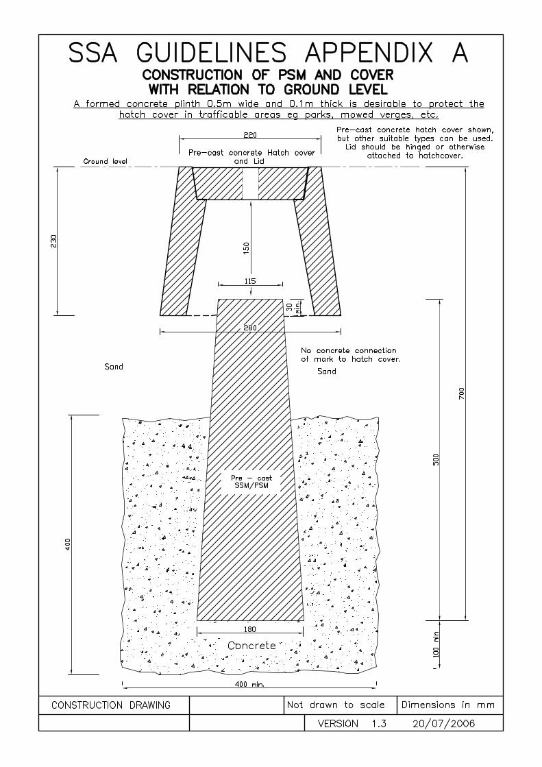
There should be at least one PSM placed for every 50 new lots created in a development. Marks must be placed such that every lot corner within the plan of a town or suburban subdivision is within 100 metres of a PSM or PCM. There must be at least 2 PSMs or PCMs that remain inter-visible one to another after the subdivision has been built up, for each plan. Additional PSMs and PCMs are to be placed in accordance with the spatial coverage stated above, such that from each PSM or PCM at least two others are visible at the time of the survey, and at least one remains visible after the subdivision has been built up. Where practicable and safe, it is desirable that a witness post and sign be placed at each PSM to indicate the presence of a survey mark. PSMs must consist of solid material and be put in so as to be firm and stable, with a hatch cover where appropriate. They are to be placed in positions that can reasonably be expected to remain safe from disturbance in the long term. Lids should be hinged or otherwise attached to the hatch cover to reduce the risk of personal injury and/or property damage for members of the public. Legal advice is that a more secure lid would lessen the risk of legal action against a surveyor. A formed concrete plinth 0.15 m wide and 0.1m thick is desirable to protect the hatch cover in trafficable areas eg parks, mowed verges etc. The required form for a PSM is a brass plaque inscribed survey mark or a steel rod measuring at least 300 millimetres in length and 10 millimetres in diameter set in a concrete block measuring at least 150 millimetres square at the top, 250 millimetres square at the base and 500 millimetres in depth. If pre-cast marks are used, construction should be in accordance with Appendix A.
Suggested forms of PCMs (not an exhaustive list) are as follows:
· Steel spike as in regulation 38, or deck spike, driven flush in a solid, paved surface, · Ramset plug (or similar) fixed into a solid, paved surface
· Steel spike as in general regulation 38 set in concrete, and
guidelines for ssa's_v9.0_approved.doc Page 8 of 18

· Centre-punched star picket set in concrete.
A steel spike as in general regulation 38, or a suitable alternative mark, shall be placed at all truncated road intersection points.
5.2 Marking Only When Safe
The final lot corner marks, PSMs and PCMs associated with any plan being surveyed within these guidelines should only be placed when they are considered to be safe from disturbance, and should remain visible after substantial completion of the servicing of the subdivision (generally after all earthworks have been completed, roads have been kerbed and sealed, sewers and drainage installed and the verge surfaces smoothed).
5.3 Marking Corners on Walls
When a lot corner is on top of a high perimeter wall or on the far side of such a wall, a mark (either additional or replacement and not necessarily a peg) should be placed on the side boundary but within the lot to indicate the side boundary to the proprietor and builder.
5.4 Inaccessible Corners and Eccentric Marking
Where a lot corner is inaccessible an eccentric (offset) mark should be placed in a position that clearly indicates the position of the boundaries.
To avoid eccentric (offset) marking being misinterpreted as corner marking, some indication should be made that the offset mark is not at the lot corner. This may be achieved by indicating with a waterproof pen on the wall or a nearby stake that the mark is a certain distance from the corner. Where possible, numbering should be carried out in such a manner that indicates the mark is not at the corner.
5.5 Deferred Final Marking
Authorisation may be obtained to defer the final marking until after the plan is put “in order for dealings” in cases where a development is fully bonded or where other exceptional circumstances exist. To use this option an application must be made to the Manager Survey Inspection who will assess the situation and may grant a conditional approval under general regulation 26A (1). Strict compliance with any conditions imposed is necessary. See guidelines 9.4 and 9.5 also.
guidelines for ssa's_v9.0_approved.doc Page 9 of 18
6.0 MARKING RURAL SUBDIVISIONS
In rural-residential and rural areas there should be at least one PSM placed for each subdivisional plan. A PSM or PCM should be situated within 200 metres of every lot corner. Referenced corners and intermediate spikes can be regarded as being equivalent to PCMs but they will only be integrated into the SCDB as a normal cadastral mark unless included within the control network. Intermediate spikes should be placed on every boundary such that (in addition to the requirement of general regulation 39) from each end mark or intermediate mark on that boundary, another mark should be visible on line in both directions (allowing that a target up to 2 metres high may be used). Where these guidelines apply to a rural or rural residential subdivision that is marked before development works have been completed, and where the lot marking is not expected to be disturbed, the surveyor is required to:
• Comply with guidelines 2.1 to 2.3, and • Include in the deposited plan(s) for the subdivision “Survey Information
Sheets” that provide details of any new reference and/or permanent control marks placed.
Where no control survey is carried out, the cadastral alignments can be regarded as adequate control.
7.0 FINAL CONTROL SURVEY
The final control survey that establishes the PSMs and PCMs from which the lots are pegged essentially “references” the subdivision to the geodetic or mapping datum. Details of the observations made for the final control survey are to be included in a CSD file lodged as an electronic field book (eFB) at Landgate via e-mail within 7 days of lodging the relevant survey sheet. Deposited plans not subject to deferred final marking (see guideline 5.5) will not be made in order for dealings until there has been received at Landgate a survey sheet, an FSC (see guideline 9.1) and an eFB relevant to the final marking on the survey sheet.
The relationship between the new control established in the eFB and the surround and/or the initial control survey shown in the re-establishment and control field book must be clearly shown in the eFB. The eFB is also to include the observations that establish any stage or intermediate control that was used to supplement the initial control contained in the re-establishment and control field book (see guideline 3.2). These control points will be classed as Temporary Control Points (TCMs). If further re-establishment of original cadastral alignments is carried out in conjunction with the intermediate control, then the re-establishment and
guidelines for ssa's_v9.0_approved.doc Page 10 of 18

connections to control must be lodged in a field book in accordance with guideline 3.2. Guideline 8.3 must be followed when showing control point numbers.
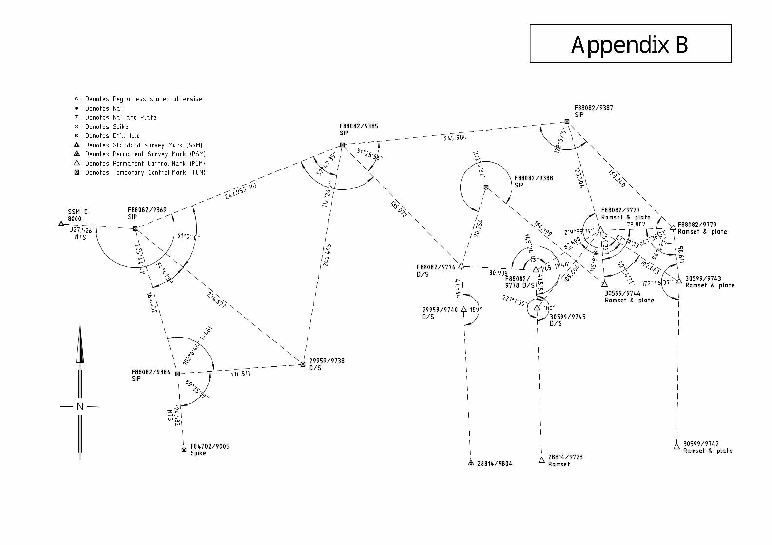
The Manager Cadastral Plans at Landgate can be contacted via e-mail at [email protected] or by fax on 9273 7670 to obtain a pre-allocated field book number for the eFB. The eFB is to be e-mailed (as an attachment) to Landgate at [email protected]. An e-lodgement self-assessment form (eSAF) is to be used for each eFB lodged. The form is to be a separate attachment (PDF) in the same e-mail. The eSAF is to be completed in accordance with the example shown in Appendix D. The e-mail must identify each mark according to type such as PSM, PCM or TCM. This can be achieved by either including a list of the control point numbers with respective mark types within the body of the e-mail, or by attaching an image (PDF) that illustrates the control point numbers and mark types. See Appendix B for an example. 7.1 eFB_CSD file
The name of the CSD file lodged as the eFB is to be prefixed by the field book number allocated and include CSD as the extension. (Eg. eFB90000.CSD)
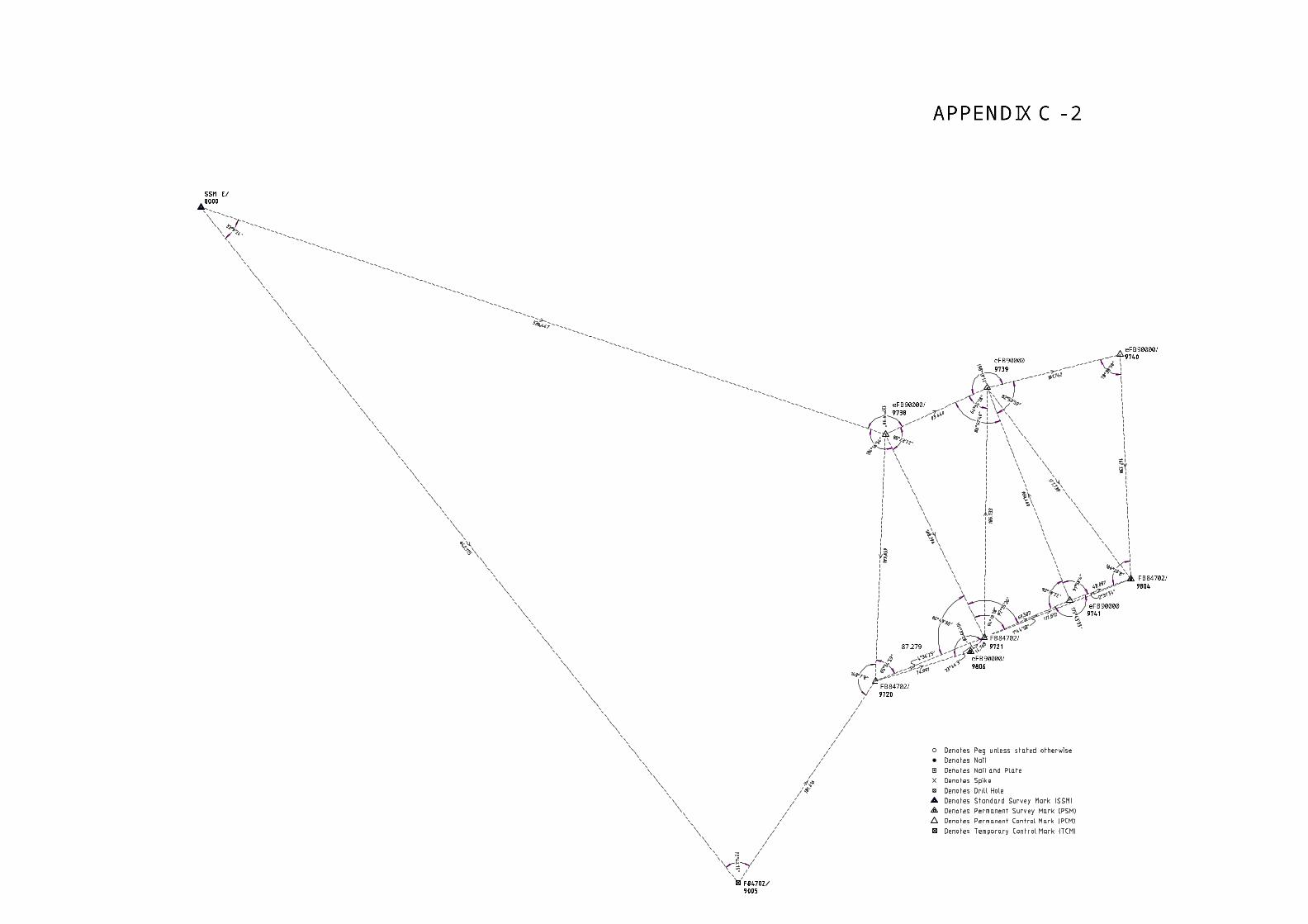
All observed control values (angles and distances) should be included in the CSD file (eFB). The local point numbers are to be used when creating the CSD file but the full name of the SSM, PSM or PCM or TCM including the FB or eFB prefix must be included in the “pntlabel” attribute of the point record (Record ID 10) for each point contained in the CSD file. (Eg eFB90000/8569) The DP number(s) to which the eFB is relevant to should be noted in record 1 of the CSD file as shown in Appendix C.
Until further notice, TCMs, PSMs and PCMs are to be given point types T in the CSD file. Landgate will amend the point types for PSMs and PCMs during integration. TCMs will always retain the T point type. The CSD file for the final control survey is to follow the requirements outlined in the CSD User Guide shown in the “Survey and Plan Practice Manual” with reference to the above which are specific to these guidelines. A graphical example of a final control network and related CSD file (eFB) has been included in Appendix C.
guidelines for ssa's_v9.0_approved.doc Page 11 of 18

7.2 eFB Certification For the purposes of certification by a licensed surveyor under regulation 17 of the Licensed Surveyors (Guidance of Surveyors) Regulations 1961 the eFB lodged for the final control survey is to be regarded as forming part of that plan (ie. the licensed surveyor who signs the plan (Regulation 54 Certificate) is responsible for the survey in the eFB. (See also guideline 8.1)
7.3 eFB miscellaneous matters The eFB may be noted on the FSC at the surveyor’s discretion. In cases where an eFB is not required a statement to that effect should be included with the FSC. An eFB is not required for a survey sheet when all of the control points on that survey sheet have already been contained in a previously lodged eFB or field book. Each control point will retain the original point name.
8.0 SURVEY SHEETS 8.1 Survey Sheets
Separate sheets are to be added to deposited plans showing the relationships between the control and/or reference marks and the new cadastral alignments. For survey-strata schemes within Special Survey Areas this information must be included in the final control field book and not added to the plan.
Every deposited plan within a SSA requires a survey sheet, and every survey-strata plan within a SSA requires a final control field book. A separate Regulation 54 Certificate is required to be shown on the Survey Sheet(s) if the surveyor signing that sheet is different to the surveyor who initially signed the Certificate on sheet 1 of the deposited plan. In this case the surveyor signing the Survey Sheet(s) will also be responsible for the eFB. (See guideline 7.2) Each PSM and PCM must have at least one direct boundary connection, and there must be a minimum of four such connections to cadastral alignments within the plan. Survey Sheets should give some indication of what type of mark is used for each PSM and PCM.
At the discretion of the surveyor, Survey Sheets may show additional information, such as connections to street infrastructure, for locating PSMs and PCMs.
guidelines for ssa's_v9.0_approved.doc Page 12 of 18

8.2 Sheet headings
To clearly indicate the purpose of the Survey Sheet(s), they are to have a bold heading which states “Survey Information Only”. A heading of “Survey Sheet” should also be included.
8.3 Numbering of Control Points
Unique control point numbers must be used for each stage of a development. Duplication of point numbers with adjoining stages or subdivisions must be avoided. It is recommended that surveyors subdividing adjoining parcels discuss control-numbering issues as soon as possible.
Intermediate and final control points (PSMs and PCMs) are to be numbered as a string by reference to the eFB number and the surveyors local point number. (Eg. eFB84702/9005)
Initial control points known as Temporary Control Marks (TCMs) that are recorded in the surround/re-establishment/control survey field book are to be numbered as a string by reference to the field book number and the surveyors local point number (eg FB80702/9000). If a surveyor connects the intermediate and final control network to a mark that was not initially numbered in a previously lodged field book contact should be made with the Inspecting Surveyors at Landgate. The e-FB or field book prefix used for control point numbers should be that book number in which the control point was initially created and which shows the initial observations used to fix that control point.
Any replacement marks should be allocated a new point number to avoid confusion and potential errors.
8.4 Angles, Mid-Azimuths and Bearings
All observed values for the final control survey should be contained in a CSD file and lodged as an eFB as indicated in guideline 7.1. If measured traditionally then observed angles and distances are to be shown in the CSD file. If GPS is used for observing the control network then angles calculated from the end azimuths and the mean ground level distances are to be shown in the CSD file (eFB).
Bearings should be used on the Survey Sheet(s) in lieu of angles to depict connections from control marks to cadastral alignments and to show road casement details (ie. road alignments) provided some indication is made as to the datum. Where bearings and mid-azimuths
guidelines for ssa's_v9.0_approved.doc Page 13 of 18
are used on the plan there must be a clear indication of what values are being used. To avoid possible orientation errors and to provide connectivity it is requested that surveys of abutting developments by the same survey firm retain the datum used on that preceding adjacent development.
8.5 Rounding Errors
Survey Sheets added to deposited plans should record to three decimal places the following values: (unless shown on previous sheets of the plan)
• the total distances of all road straights, (preferably between intersection spikes);
• all truncation set-back distances; and • frequent connections across roads.
The purpose of this information is to reduce errors in future re-establishment caused by rounding errors or accumulation of errors.
8.6 Lot dimensions not to be shown on Survey Sheet
Angles and distances around new lots should not be shown on the Survey Sheet(s). This information is already contained within the previous sheet(s) of the plan.
8.7 Curved Boundaries
If the plan has boundaries that are circular curves, full curve details must be recorded somewhere on the plan.
8.8 Depiction of Non-Standard Marks
If non-standard marks or eccentric marks are used then they shall be depicted on the Survey Sheet(s).
8.9 Delete WAPC Approval Box
The WAPC approval box must be struck through on all Survey Sheets.
9.0 SURVEY CERTIFICATES AND ADMINISTRATION 9.1 Final Survey Certificates
A Final Survey Certificate (FSC) in the form in the Table to this guideline must be lodged with the Inspector of Plans and Surveys before the deposited plan of any subdivision surveyed in accordance
guidelines for ssa's_v9.0_approved.doc Page 14 of 18
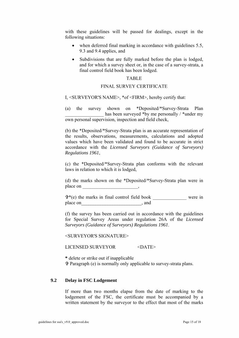
with these guidelines will be passed for dealings, except in the following situations:
• when deferred final marking in accordance with guidelines 5.5, 9.3 and 9.4 applies, and
• Subdivisions that are fully marked before the plan is lodged, and for which a survey sheet or, in the case of a survey-strata, a final control field book has been lodged.
TABLE
FINAL SURVEY CERTIFICATE I, <SURVEYOR'S NAME>, *of <FIRM>, hereby certify that: (a) the survey shown on *Deposited/*Survey-Strata Plan ________________ has been surveyed *by me personally / *under my own personal supervision, inspection and field check, (b) the *Deposited/*Survey-Strata plan is an accurate representation of the results, observations, measurements, calculations and adopted values which have been validated and found to be accurate in strict accordance with the Licensed Surveyors (Guidance of Surveyors) Regulations 1961, (c) the *Deposited/*Survey-Strata plan conforms with the relevant laws in relation to which it is lodged, (d) the marks shown on the *Deposited/*Survey-Strata plan were in place on _______________________,
*(e) the marks in final control field book ______________ were in place on_________________________, and (f) the survey has been carried out in accordance with the guidelines for Special Survey Areas under regulation 26A of the Licensed Surveyors (Guidance of Surveyors) Regulations 1961. <SURVEYOR'S SIGNATURE> LICENSED SURVEYOR <DATE> * delete or strike out if inapplicable
Paragraph (e) is normally only applicable to survey-strata plans.
9.2 Delay in FSC Lodgement
If more than two months elapse from the date of marking to the lodgement of the FSC, the certificate must be accompanied by a written statement by the surveyor to the effect that most of the marks
guidelines for ssa's_v9.0_approved.doc Page 15 of 18
of the subdivision remained in place at the date of lodgement of the FSC.
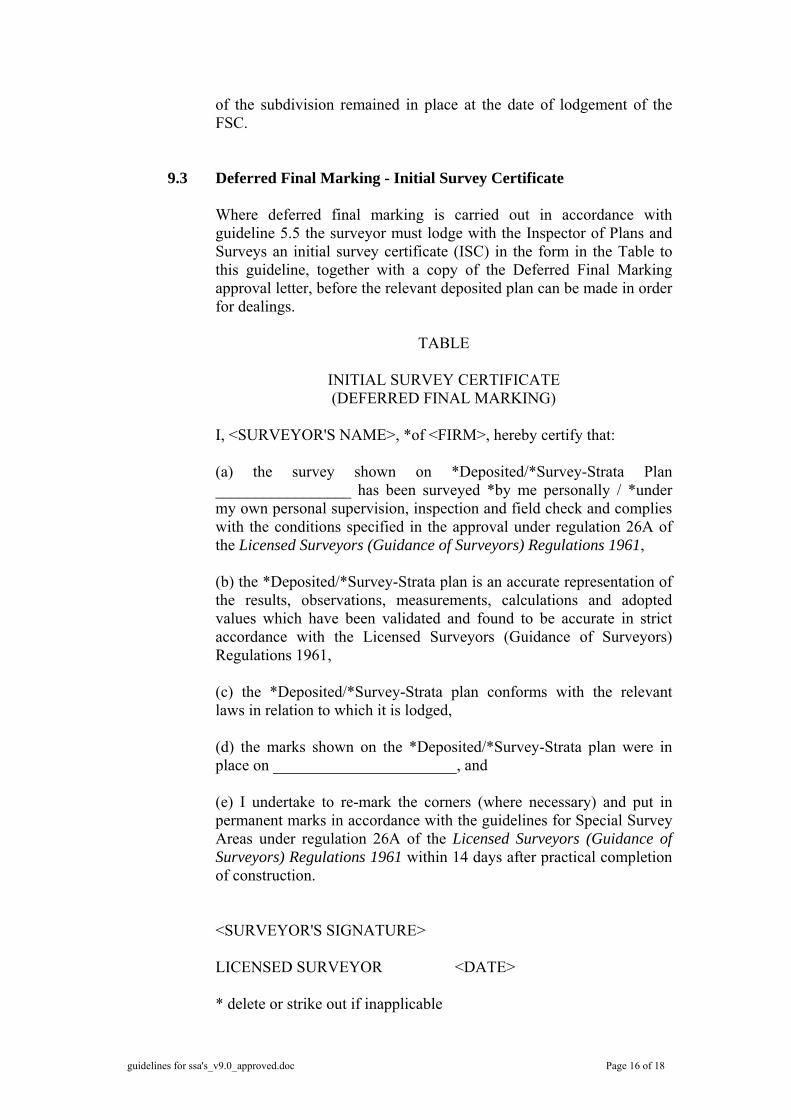
9.3 Deferred Final Marking - Initial Survey Certificate
Where deferred final marking is carried out in accordance with guideline 5.5 the surveyor must lodge with the Inspector of Plans and Surveys an initial survey certificate (ISC) in the form in the Table to this guideline, together with a copy of the Deferred Final Marking approval letter, before the relevant deposited plan can be made in order for dealings.
TABLE
INITIAL SURVEY CERTIFICATE (DEFERRED FINAL MARKING)
I, <SURVEYOR'S NAME>, *of <FIRM>, hereby certify that:
(a) the survey shown on *Deposited/*Survey-Strata Plan _________________ has been surveyed *by me personally / *under my own personal supervision, inspection and field check and complies with the conditions specified in the approval under regulation 26A of the Licensed Surveyors (Guidance of Surveyors) Regulations 1961, (b) the *Deposited/*Survey-Strata plan is an accurate representation of the results, observations, measurements, calculations and adopted values which have been validated and found to be accurate in strict accordance with the Licensed Surveyors (Guidance of Surveyors) Regulations 1961, (c) the *Deposited/*Survey-Strata plan conforms with the relevant laws in relation to which it is lodged, (d) the marks shown on the *Deposited/*Survey-Strata plan were in place on _______________________, and (e) I undertake to re-mark the corners (where necessary) and put in permanent marks in accordance with the guidelines for Special Survey Areas under regulation 26A of the Licensed Surveyors (Guidance of Surveyors) Regulations 1961 within 14 days after practical completion of construction.
<SURVEYOR'S SIGNATURE> LICENSED SURVEYOR <DATE> * delete or strike out if inapplicable
guidelines for ssa's_v9.0_approved.doc Page 16 of 18

9.4 Deferred Final Marking - Final Survey Certificate
Where deferred final marking is carried out in accordance with guideline 5.5 the surveyor must lodge with the Inspector of Plans and Surveys a final survey certificate in the form in the Table to this guideline.
TABLE
FINAL SURVEY CERTIFICATE (DEFERRED FINAL MARKING)
I, <SURVEYOR'S NAME>, *of <FIRM>, hereby certify that:
(a) the survey shown on *Deposited/*Survey-Strata Plan ........................... has been re-surveyed *by me personally / *under my own personal supervision, inspection and field check, (b) the *Deposited/*Survey-Strata plan is an accurate representation of the results, observations, measurements, calculations and adopted values which have been validated and found to be accurate in strict accordance with the Licensed Surveyors (Guidance of Surveyors) Regulations 1961, (c) the *Deposited/*Survey-Strata plan conforms with the relevant law in relation to which it is lodged, (d) the marks shown on the *Deposited/*Survey-Strata plan were in place on ...........................,
*(e) the marks in final control field book ______________ were in place on_________________________, and (f) the survey has been carried out in accordance with the guidelines for Special Survey Areas under regulation 26A of the Licensed Surveyors (Guidance of Surveyors) Regulations 1961. <SURVEYOR'S SIGNATURE> LICENSED SURVEYOR <DATE>
* delete or strike out if inapplicable
Paragraph (e) is normally only applicable to survey-strata plans.
guidelines for ssa's_v9.0_approved.doc Page 17 of 18
9.5 Delivery to WAPC
Surveyors must submit a release letter before plans will be delivered to WA Planning Commission (WAPC). Plans will not be made in order for dealings until WAPC approval has been endorsed and the ISC (if applicable), FSC (when required), survey sheet(s) or final control field book (if applicable), and e-FB have been lodged.
10.0 RE-SUBDIVISIONS AND RE-SURVEYS WITHIN SPECIAL SURVEY
AREAS
Any re-subdivision of a lot or lots within a Special Survey Area must comply with these guidelines (i.e. once an SSA, always an SSA). Where original control or referencing is replaced or enhanced the information is to be included in Survey Sheet(s) added to the new subdivision plan, or in the case of a survey-strata, lodged in a field book.
Any re-survey of a lot or lots within a Special Survey Area must comply with Regulation 8(2) of the Licensed Surveyors (Guidance of Surveyors) Regulations 1961. Where original control or referencing is replaced or enhanced the information is to be included in a field book.
Original cadastral corners should be re-positioned from the closest available reliable permanent marks (SSMs, PSMs, PCMs, intersection spikes or referenced corners). Only in circumstances where no permanent marks remain within a Special Survey Area should the spatially upgraded SCDB coordinates be the sole source to position cadastral corners. Field books from the original plan are not to be brought forward on plans of re-subdivision. These guidelines approved as amended by the LSLB on 23 November 2006 NEIL BROWNE CHAIRMAN
guidelines for ssa's_v9.0_approved.doc Page 18 of 18
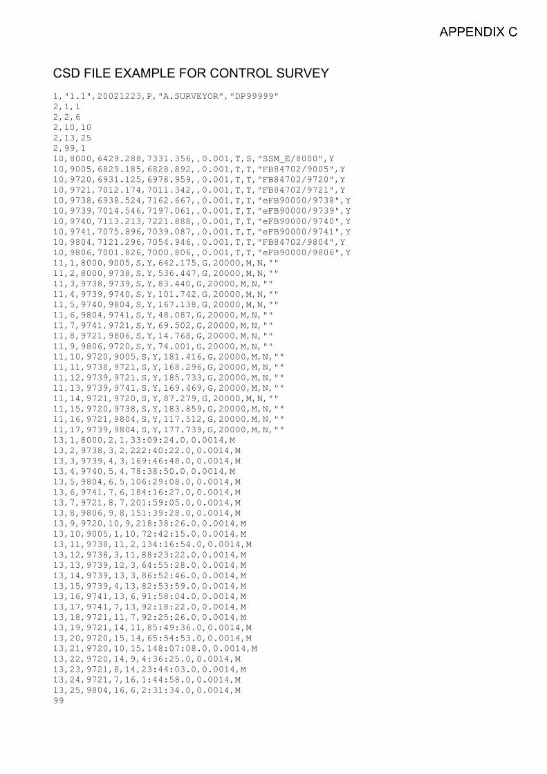
CSD FILE EXAMPLE FOR CONTROL SURVEY1,"1.1",20021223,P,"A.SURVEYOR","DP99999"2,1,12,2,62,10,102,13,252,99,110,8000,6429.288,7331.356,,0.001,T,S,"SSM_E/8000",Y10,9005,6829.185,6828.892,,0.001,T,T,"FB84702/9005",Y10,9720,6931.125,6978.959,,0.001,T,T,"FB84702/9720",Y10,9721,7012.174,7011.342,,0.001,T,T,"FB84702/9721",Y10,9738,6938.524,7162.667,,0.001,T,T,"eFB90000/9738",Y10,9739,7014.546,7197.061,,0.001,T,T,"eFB90000/9739",Y10,9740,7113.213,7221.888,,0.001,T,T,"eFB90000/9740",Y10,9741,7075.896,7039.087,,0.001,T,T,"eFB90000/9741",Y10,9804,7121.296,7054.946,,0.001,T,T,"FB84702/9804",Y10,9806,7001.826,7000.806,,0.001,T,T,"eFB90000/9806",Y11,1,8000,9005,S,Y,642.175,G,20000,M,N,""11,2,8000,9738,S,Y,536.447,G,20000,M,N,""11,3,9738,9739,S,Y,83.440,G,20000,M,N,""11,4,9739,9740,S,Y,101.742,G,20000,M,N,""11,5,9740,9804,S,Y,167.138,G,20000,M,N,""11,6,9804,9741,S,Y,48.087,G,20000,M,N,""11,7,9741,9721,S,Y,69.502,G,20000,M,N,""11,8,9721,9806,S,Y,14.768,G,20000,M,N,""11,9,9806,9720,S,Y,74.001,G,20000,M,N,""11,10,9720,9005,S,Y,181.416,G,20000,M,N,""11,11,9738,9721,S,Y,168.296,G,20000,M,N,""11,12,9739,9721,S,Y,185.733,G,20000,M,N,""11,13,9739,9741,S,Y,169.469,G,20000,M,N,""11,14,9721,9720,S,Y,87.279,G,20000,M,N,""11,15,9720,9738,S,Y,183.859,G,20000,M,N,""11,16,9721,9804,S,Y,117.512,G,20000,M,N,""11,17,9739,9804,S,Y,177.739,G,20000,M,N,""13,1,8000,2,1,33:09:24.0,0.0014,M13,2,9738,3,2,222:40:22.0,0.0014,M13,3,9739,4,3,169:46:48.0,0.0014,M13,4,9740,5,4,78:38:50.0,0.0014,M13,5,9804,6,5,106:29:08.0,0.0014,M13,6,9741,7,6,184:16:27.0,0.0014,M13,7,9721,8,7,201:59:05.0,0.0014,M13,8,9806,9,8,151:39:28.0,0.0014,M13,9,9720,10,9,218:38:26.0,0.0014,M13,10,9005,1,10,72:42:15.0,0.0014,M13,11,9738,11,2,134:16:54.0,0.0014,M13,12,9738,3,11,88:23:22.0,0.0014,M13,13,9739,12,3,64:55:28.0,0.0014,M13,14,9739,13,3,86:52:46.0,0.0014,M13,15,9739,4,13,82:53:59.0,0.0014,M13,16,9741,13,6,91:58:04.0,0.0014,M13,17,9741,7,13,92:18:22.0,0.0014,M13,18,9721,11,7,92:25:26.0,0.0014,M13,19,9721,14,11,85:49:36.0,0.0014,M13,20,9720,15,14,65:54:53.0,0.0014,M13,21,9720,10,15,148:07:08.0,0.0014,M13,22,9720,14,9,4:36:25.0,0.0014,M13,23,9721,8,14,23:44:03.0,0.0014,M13,24,9721,7,16,1:44:58.0,0.0014,M13,25,9804,16,6,2:31:34.0,0.0014,M99

DLI Sales Order No
OFFICE USE ONLY
CHECKED
Valid from 10th July, 2006
NUMBER OF LOTS
TOTAL FEE PAYABLE
ABN 86 574 793 858
MEMORIAL FEE
LODGING PARTY
REFERENCENUMBER &DESCRIPTION