Embed Size (px)
Citation preview

Surveying & Installation Guide
the professional installation
Issue 2 January 2008

the professional installation

Issue: 2 (January 2008) 1
Surveying & Installation - Index
Surveying & Installation - Introduction Page 3
Surveying & Installation - Terminology Page 4 - 5
Surveying - Replacement Window and Doorsets Page 6 - 11
Surveying - Removal of Window and Doorsets Page 12
Site Safety Page 13
Installation - Window and Doorsets Page 14 - 19
Examples - Typical Checklists Page 20 - 21
Removal Techniques - Window and Doorsets Page 22 - 25
Frame Positions and Joint Construction Page 26 - 28
Bibliography Page 31
Notes Page 29 - 30
the professional installation

Issue: 2 (January 2008) 2
the professional installation

Surveying & Installation - Introduction
BS 8213 - 4: 2007Windows, Doors and Rooflights -
Part 4: Code of Practice for the Survey and Installation of Windows and External Doorsets
As of March 2007, British Standard BS 8213-4: 2007 came into effect, the Code of Practice for the Survey and Installation of Windows and External Doorsets. In previous years the code of practice was issued by the BPF (British Plastics Federation) however, this has now become a more controlled and managed document under the British Standard flag.
The document is used as a basis for obtaining a BSI kitemark for Surveying and Installation.
The BS 8213 gives recommendations for the surveying and installation of NON LOADBEARING windows and doorsets of any material, which are installed vertically into the external face of a structure.
The standard gives guidance on good practices necessary for successful surveying and installation of windows and doorsets into new build and replacement situations.
The standard is mainly aimed at installation of frames into dwellings, however much of the document guidance can also be relevant to other types of installation.
The document however does not cover curtain walling or load bearing windows and doorsets.
Issue: 2 (January 2008) 3

Bow Window:
Bay Window:
Frame:
Gallows Bracket:
Installation Packer:
Door Assembly / Door set:
Dormer WindowOr Mansard Roof:
DPM(Damp Proof Membrane):
Finishing:
Fixing:
A type of bay window, usually carrying only light loads, which does not form an extension to the floor area of theroom.
Surround to a door leaf, window sash etc enabling it tobe fixed into position, also referred to as an Outerframe.
A triangular bracket used on the underside of a bay / bow window construction to provide support (See bay /bow window)
Packing piece used in gaps at fixing points to obtain rigid fixing and prevent distortion (Also known as a fixingpacker) - Usually a “U” Shape made of plastic.
Complete assembly as installed, includes the door frame, the door sash together with the hardware
Vertical, or near vertical (up to 15°), window built into and projecting from a pitched roof structure.
A layer or strip of impermeable material, placed within a wall, chimney or similar constructons to prevent thepassage of moisture
Final covering and treatment of surfacesE.g: Plaster, Render, Cladding etc
Component that is used to secure separate parts of the window or doorset to each other, to secure an item of hardware to a window or door part or to secure the completed window or doorset into the structural opening.
Mansard Dormer
When three or more frames are fixed together and they all project beyond the main face of the building. The brickwork above and below the window frames follow the contours of the actual window frame, therefore allowing a person inside the building to walk into the bay area created.
At Least 150mmAbove Ground
Dpc
Surveying & Installation - Terminology
Issue: 2 (January 2008) 4

Manufacturing Sizes:
Structural Opening:
Structural Opening Size:
Surveyor:
System Supplier:
Sealant:
The overall dimensions for the door / window whichresult from making the approprite deductions from the structural opening size. Also known as Work Size.
Aperture in a wall into which a window or doorset is to be installed.
Size of the maximum rectangular shape which can be fitted within the structural opening.
Qualified or otherwise competent person who is capable of surveying for window and doorset installation, advising on suitable design, carrying out a risk assessment as necessary, and assessing the quality of the finished installation.
Original source of the design and / or supply ofcomponents used in the fabrication of a window or door.
A compressible material used to seal around theperimeter of a window / door in the structural opening toprevent air and water penetration, commonly made ofsilicone, butyl tape, or polysulfide.
Installer:
Lintel:
Company and / or individual carrying out the works of fitting the window / door.
Beam which supports loads over a structural opening.Can be made of steel, reinforced concrete, timber etc or steel mesh fixed between brick courses.
Surveying & Installation - Terminology
Issue: 2 (January 2008) 5
the professional installation

General: Surveyor
Good surveying is the basis of ensuring a quality installation.
Surveyors should be fully trained in window and doorset installation techniques and be aware of the manufacturers recommendations for the particular window / door system being used and maximum manufacturing sizes.
In order to comply with the building regulations, it is advisable to make notes and photograph the window / door style which is being replaced along with sizes and of the opening lights and mullion / transom positions.
The surveyor will be able to inform the purchaser / owner of any enhancements that could be made with respect to security issues and possible ventilation.
Risk assessment must be carried out for window / doorset design.
Risk assessment for the installation must also be carried out.
Where load-bearing situations occur, the system suppliers recommendations must be followed.
Check that replacement window / doorsets will not infringe any Local Authority planning controls i.e Conservation, Article 4 Direct.
Make Notes Take Photographs Risk Assessment
Surveying - Replacement Window & Doorsets
Issue: 2 (January 2008) 6

General : Surveyor
Surveyor to check aperture for damage / defects and inform purchaser / owner accordingly.
Check if aperture has any electrical wiring, telephone cables etc present ornear by.
Check for presence of curtain rails. Important if the window/ door is inward opening.
Surveyor should determine the design wind load for the application andwhether the window / door is suitable for the application.
The surveyor should check that there is a lintel present above the window /door or alternatively look into providing support should it be required.
Bow, Oriel and Dormer windows may in some cases require to be load bearing,and therefore reference to the system suppliers instructions must be made.
For coupled window / doorsets, the surveyor must determine the method to be used taking into account wind and dead loads, aesthetics and coupling positions.
Ensure BS8213-1 is complied with regarding window style to provide safety in use and cleaning (i.e Easyclean hinges)
Surveying - Replacement Window & Doorsets
Check Aperture for Defects
Check forWires / Cables
Wind Load Check
Check LintelCheck for Curtain Rails
Issue: 2 (January 2008) 7

Surveyor is to confirm with purchaser / owner whether the window / door is be inward or outward opening and confirm the handing. Note: Outward opening window / doors into pedestrian areas must be taken into account.All surveys are taken as being viewed externally - Always check and confirm this is the case.
Surveyor is to advise on restriction devices particularly on outward opening windows / doors to prevent damage caused by sudden wind gusts.
Surveyor when dealing with doorsets should take into consideration the threshold types (Disability access), letterplate sizes and positioning, hardware specification and side panel specifications all clearly identified tothe purchaser / owner.
Where bricks are to be removed to install a product, the cavity closing method must be specified. It is recommended that you consult the localauthority building control for advice and interpretation of local regulations.
The surveyor should specify or confirm the drainage method for the window / door frame and / or glazing.
Glazing, including position, style, orientation, pattern / decoration, lead, georgian bar should be specified by the surveyor.
General : Surveyor
Surveying - Replacement Window & Doorsets
Additional Hardware?
Removing Brickwork?
Confirm Drainage Method
Glass Specification
Inward or Outward
Opening?
Issue: 2 (January 2008) 8

The surveyor should indicate safety glass requirements and positions in accordance with the Building Regulation (Approved Document N) whereappropriate.
Approved Document N - Part N1 - Glazing - Protection Against Impact
Glazing with which people are likely to come into contact whilst moving in or about the building shall:
If broken on impact, break in a way which is unlikely to cause injury, or
Resist impact without breaking, or
Be shielded or protected from impact.
Part N1 specifies the areas where safety glazing is required to be installed and is supported by by detailed British Standard documentation.
Critical Locations in Internal and External Walls - Part N1
Shaded areas show critical locations towhich Part N1 applies
( i.e Glazing areas 2,4,5,6,7,8,11 )
1
6
2
7
3
8
54 9 10
11
General : Surveyor
Surveying - Replacement Window & Doorsets
Doors and Side Panels Window
Floor Level
Issue: 2 (January 2008) 9

Measurement of Flat Windows & Doorsets
Step 1: Take 3no. Horizontal Dimensions Step 2: Take 3no. Vertical Dimensions
Step 3: Take 2no. Diagonal Dimensions
Measurement of an opening: Three measurements of and should be taken across the opening, along with the squareness of the aperture by taking measurements. The smallest measurement of height andwidth will determine the manufacturing size.
width height
diagonal
General : Surveyor
Surveying - Replacement Window & Doorsets
The need for any sub-cill should be determined. The size of the sub-cilloverhang should be such that it is an overhang of at least 25mm from the faceof the brickwork to the inner edge of the cill overhang. The surveyor willdetermine the method of fixing, check requirements for cill horns and how any “making good” is to be carried out.
The difference between internal and external reveal sizes should be determined and checks made to the operation of the opening light to ensure it is not impeded by plaster, render or tiles etc.
Brickwork
Brickwork
Brickwork
Horizontal Dim
Horizontal Dim
Horizontal Dim
1
1
1
2
2
2
3
3
Issue: 2 (January 2008) 10
Ver
ical
Dim
t
Ver
ical
Dim
t
Di gonal Dm
a
iDiagonal Dim
Ver
ical
Dm
ti

Manufacturing Sizes: Due to temperature fluctuations, PVCu windows and doors can expand and contract. This needs to be taken into account when calculating the finished frame size in relation to the aperture. The table below highlights the recommended deductions for the width and height of a frame.
General : Surveyor
Surveying - Replacement Window & Doorsets
These deductions are from the TOTAL width and height, and not “per side”.
The gap required for effective polyurethane foam fixing at the head is 10 - 15mm.
NOTE: When the overall width or height exceeds 3.0m, intermediate expansion joints may be required.
NOTE: BS7412 limits window sizes up to 3.0m only.
Material:
Recommended Deduction for Width and Height of Structural Opening.
All dimensions in millimetres (mm)
Up to 1.5m
GRP 5 15 15
PVC-U : White 10 10
10
15 20
PVC-U : Non White 15 15 22 28
Timber 10 10 10 15
Steel 8 12 15
Aluminium 10 10
10
15 20
From 1.5m to 3.0m From 3.0m to 4.5m From 4.5m
Issue: 2 (January 2008) 11

The installation team should ensure that all relevant documentation isavailable and clearly understood. i.e Drawings, Survey Sheets, Specialist Instructions etc
Check and double check sizes, type and condition of all windows and doorsagainst the survey sizes, type and against the actual aperture size, prior to any removal operations.
Prior to commencement of work, the purchaser / owner must be given adequate notice to remove any furniture, fixings or fittings.
The installer is responsible for both the external and internal protection of the property during installation work by the use of clean dust sheets. Avoid debris becoming embedded in soft garden areas.
Care should be taken to avoid damage to floor coverings and to decorations.
Plan to install and seal new windows and doorsets on the same day as theexisting windows / doorsets are removed, to maintain security and weathertightness of the dwelling.
Remove existing windows /doorsets without damaging the building structure and its finishings.
Electrical wiring and other specialist cables should be routed around and away from the window / door and not through the frame. If this is not possiblethen it must be agreed by the purchaser / owner and surveyor as to analternative solution and if required a specialist service provider brought in toassist with the routing of the cables etc.
Check and Understand
Documentation
Adequate Notice for Furniture Removal
Not Sure About Wires / Cables,
Ask for Assistance
Protect Furniture / Flooring
Remove and Re-Install Same Day
General : Installer
Surveying - Removal of Existing Window & Doorsets
Issue: 2 (January 2008) 12

******* Window and Doorset removal and installation can be dangerous *******
Train new operatives in the safe use of tools.
Ensure operatives have and use correct PPE (Personal Protective Equipment)
Full training and assessment records of operatives should be kept.
Glass Handling: Wear eye protection, safety footwear, hand and wrist protection.
The use of a safe working platform to give safe access to the structural opening is essential.
Store and dispose of old windows and doorsets and other debris safely and recycle where possible. (Recovinyl)
When operating a grinding disc, safety precautions as follows should be observed:
Heavy Gloves, face visors and helmets must be Worn.
Clear access provided.
Care should be taken that sparks can not ignite combustible materials i.e dust sheets.
All personnel should be kept at a safe distance.
All electrical power tools should: Work on 110 V mains power or
Be Battery operatered or
Work on 240V with residual current detector of 30 mA maximum rating.
Training Personnel Protective Equipment
Storage and Disposal Think Safety!
Working Platforms
Health and Safety at Work Act 1974 / Control of Asbestos at Work Regulations 2002.
Glass
ElectricityPower Tools
P.P.E
Site Safety
Issue: 2 (January 2008) 13

The window / doorset must be fixed into the structural opening or to an adjacent window / doorset in order to resist all likely imposed loads which may cause the frame to deflect. These loads might be due to .............
Wind Loads
Operating Loads
Gravity (i.e Vertical Slider / Pivot / Casement)
Accidental Impact
Attempted Burglary
The fixing methods for the window / doorset can be affected by.........
The wall construction i.e cavity or not, materials
The nature and condition of any cavity
The relative position of the frame and cavity
The position of the plasterline and the need to minimizedisturbance and damage to interior decorations
The design of the reveal
General: Installer
Installation - Window & Doorsets
Issue: 2 (January 2008) 14

Two methods of fixing window / Doorset into opening or as combinations:
Through Frame Fixing
Fixing Lugs
Typical Frame Fixings
Screw fixings should penetrate at least 25mm into timber , plugged holes in brick, block or masonry.
Connections to steelwork should be made using the appropriate thread cutting screwsor with pre-tapped holes and a machine screw, or self drilling screws.
Typical Fischer Window Fixing
Machine Screw Fixing
General: Installer
Installation - Window & Doorsets
Self Drill MasonryFixing (Tapcon)
Through Frame Fixing DetailFixing Lug Detail
Issue: 2 (January 2008) 15

Fixing Distances and Positions for PVC-u Window & Doorset
Corner fixings should be between 150mm and 250mm from the external corner.
Fixings should be a minimum of 150mm from the centre line of a transom / mullion.
Each jamb and cill should have a minimum of two fixings with intermediate fixingbeing positioned at no greater than 600mm centres.
If the head is fixed with polyurethane foam, the following rules may be applied.
Frame width upto 1200mm - No fixings
Frame width 1201mm to 2400mm- One central fixing
Frame width 2401mm to 3600mm- two equally spaced fixings
All four sides of the window / doorset, where practicable, should be fixed in the opening.
Concrete and steel lintels can make it difficult to achieve the correct fixing arrangement.
Polyurethane foam is known to be beneficial to such when used in conjunction with the fixings if the correct fixing distances can not be achieved.
DO NOT USE polyurethane expanding foam as the sole method of fixing.
General: Installer
Installation - Window & Doorsets
200mm 200m
600mm Max
20
0m
m
15
0m
mM
in
50mm 50mm
50
mm
++
+
-
-
-
Issue: 2 (January 2008) 16

If used as an external lug, use either a “One Way” or security screw fixings.
Trims etc may be used to complete the interface of the frame and structure. DO NOT use the trims as a way of enhancing the weathertightness.
Coupled assemblies are delivered to site as separate units and fixed in position in accordance with the system suppliers recommendations.
Used adjacent to fixing positions toprevent frame distortion. Must be madeof a material which is resistant to compression, rot and corrosion.
Coupled Assemblies
Installation Packers
Finishings
General: Installer
Installation - Window & Doorsets
DOOR SASH
COUPLINGMULLION
OUTERFRAME
GLAZING BEAD
OUTERFRAME
REINFORCEMENT
Fixing Lugs
Issue: 2 (January 2008) 17
Drainage paths should be cleared of any debris.
Internal reveals made good in accordance with the agreement between installer and purchaser.
Remove protective tape from the window / doorset on completion of installation.
Finishing Off & Making Good
Sealing
Final Inspection
Should be carried out preferably accompanied by the purchaser / owner, and ensure that the installation is in accordance with the surveyors / manufacturers instruction.
Make the purchaser / owner aware of how to operate the door / window furniture.
General: Installer
Installation - Window & Doorsets
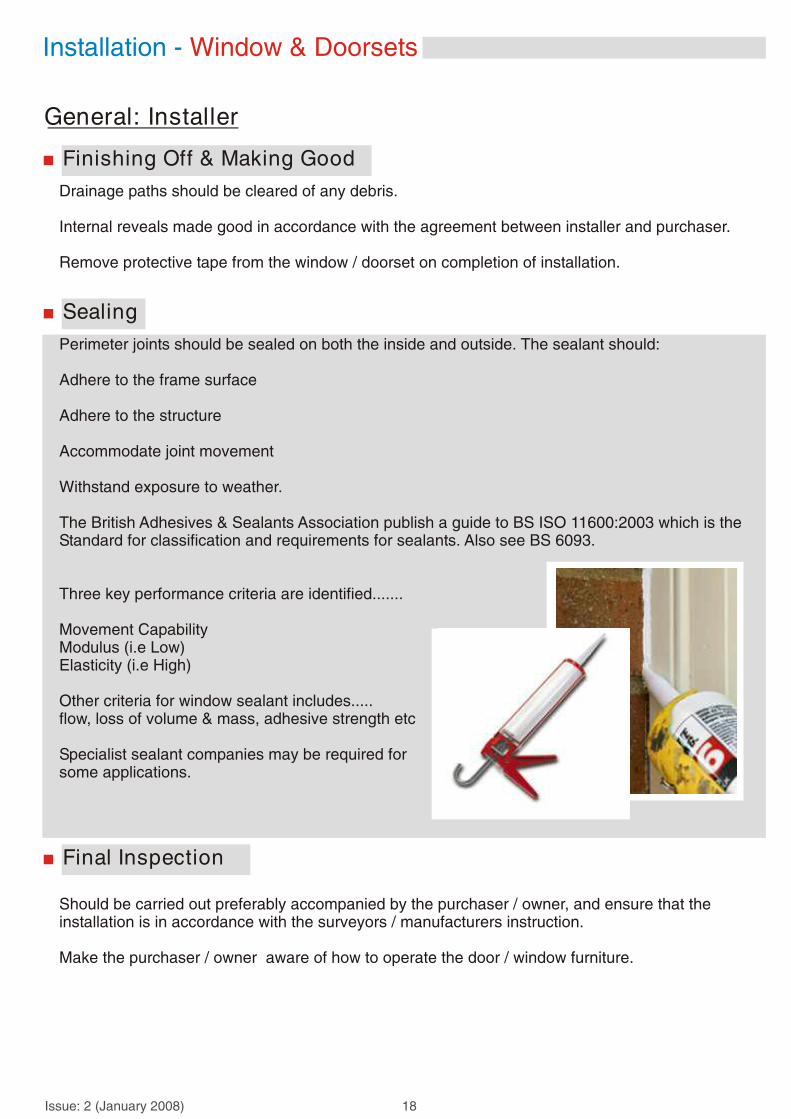
Perimeter joints should be sealed on both the inside and outside. The sealant should:
Adhere to the frame surface
Adhere to the structure
Accommodate joint movement
Withstand exposure to weather.
The British Adhesives & Sealants Association publish a guide to BS ISO 11600:2003 which is theStandard for classification and requirements for sealants. Also see BS 6093.
Three key performance criteria are identified.......
Movement CapabilityModulus (i.e Low)Elasticity (i.e High)
Other criteria for window sealant includes.....flow, loss of volume & mass, adhesive strength etc
Specialist sealant companies may be required for some applications.
Issue: 2 (January 2008) 18

All glazing should conform with the BS6262 and BS 8000-7 documentation.
Support the glass units correctly in accordance with BS 6262 with glass support and packing blocks.
Examine all glass units for damage prior to installation. Defective units should not be used.
Insulated glass units incorporating safety glass should be installed with the safety glass on the appropriate side. (Note, the marking of the safety unit must remain visible after installation).
Insulated units with Low emissivity coating should be installed in conjunction with the manufacturers instruction. Failure to do so may make the coating less effective.
Glazing
Fixed window
Residential door
Pivot windowTilt/turn window
French door
Top hung Bottom hung
Note: All sashes should bepacked at a maximum of 75mm from the corners in order that the dead load applied by the sealed units weight is distributed correctly.
See BS 6262 for further window configurations andstyles.
Viewed Internally
Window/door packing configurations
General: Installer
Installation - Window & Doorsets
Side hung
Issue: 2 (January 2008) 19

Note: It can be of benefit to make a photographic record of the existing installation in case of dispute over Building Regulations compliance at a later date
Surveyors Checklist
Examples - Typical Checklist
Y / N
Have risk assessment (s) been completed (See BS 8213-4: 2007)?
Is the condition of the aperture satisfactory and without evidence of damp / cracks?
Is the aperture square and even within 5mm height and width and 10mm diagonals?
Will any loads be carried by the building and not the window / doorset?
Has the size and method of fixing any sub-cill been determined?
Will the window / doorset function without being fouled by plasterwork etc?
Will any trickle ventilators fitted function without being fouled by plasterwork etc?
Will hinges functions without being fouled by plasterwork?
Are curtain tracks and nets clear of the proposed design?
Is the size and configuration within the manufacturers limits?
Will the products exposure category be suitable for the location?
Will the installation conform with the Building Regulations?
Is the method of drainage appropriate for the installation and product?
Has the purchaser confirmed position and handing of the opening lights?
Has any additional hardware been specified?
Is the access to the installation safe?
Has the fixing method of the window / doorset been determined?
Has the extent of “making good” been agreed with the purchaser?
Issue: 2 (January 2008) 20
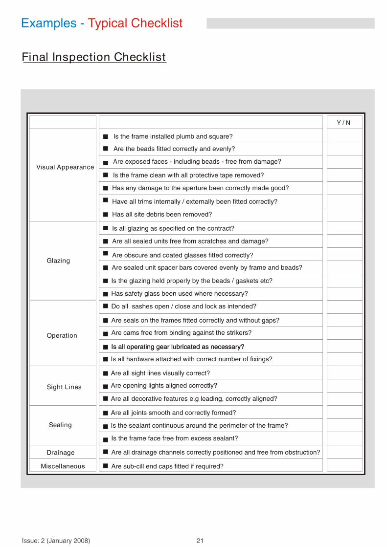
Final Inspection Checklist
Examples - Typical Checklist
Y / N
Is the frame installed plumb and square?
Are the beads fitted correctly and evenly?
Are exposed faces - including beads - free from damage?
Is the frame clean with all protective tape removed?
Has any damage to the aperture been correctly made good?
Have all trims internally / externally been fitted correctly?
Has all site debris been removed?
Is all glazing as specified on the contract?
Are all sealed units free from scratches and damage?
Are obscure and coated glasses fitted correctly?
Are sealed unit spacer bars covered evenly by frame and beads?
Is the glazing held properly by the beads / gaskets etc?
Has safety glass been used where necessary?
Do all sashes open / close and lock as intended?
Are seals on the frames fitted correctly and without gaps?
Are cams free from binding against the strikers?
Is all operating gear lubricated as necessary?Is all operating gear lubricated as necessary?
Is all hardware attached with correct number of fixings?
Are all sight lines visually correct?
Are opening lights aligned correctly?
Are all decorative features e.g leading, correctly aligned?
Are all joints smooth and correctly formed?
Is the sealant continuous around the perimeter of the frame?
Is the frame face free from excess sealant?
Are all drainage channels correctly positioned and free from obstruction?
Are sub-cill end caps fitted if required?
Visual Appearance
Glazing
Operation
Sight Lines
Sealing
Drainage
Miscellaneous
Issue: 2 (January 2008) 21

Glazed fixed light: Preferred method is removal of putty, sprigs, beads or fixing nails and removal of glass intact. Alternatively, carefully break the glass so that the fragments are on the outside of the structure.
It is good practice to run a sharp knife between the inside face of the frame and the plaster adjoining the frame, to minimize damage to the plaster when thewindow / doorset is removed.
Remove opening lights first, complete with the glass by levering the screws from the frames, or unscrew the hinges or by cutting through the hinges. This provides a larger working space and reduces the weight of the window.
After removal of opening lights and fixed light glazing, any mullion / transoms which remain can be cut through in order to remove them.
Timber Windows / Doorsets
Cutting Through Transom / Mullions Cutting Through the Outer Frame
Putty
Nails
Removal Techniques - Window & Doorsets
Issue: 2 (January 2008) 22

Problems may arise with windows/ Doorsets under the roof eaves. There might be a brick course resting on the frame between the top of the existing frame and the soffit board. This is generally decorative and not load - bearing.
Most box-sash windows were installed before cavity walls existed and are built into the internal reveals of the solid brickwork. The sashes can be removed fully glazed as follows...
Remove mitred bead from around frame.
Cut the sash cords to release and lower the weights.
Remove bottom sash, take off parting bead, remove top sash.
Cut outerframe from aperture leaving the horns in the structure.
Remove counterweight from sash box
Box Sash Windows
Removal Techniques - Window & Doorsets
Issue: 2 (January 2008) 23

Metal windows can be removed in one of the following ways.......
If the window / doorset is fixed through the frame into timber sub-frames or direct into aperture.....
Remove all glazing from fixed lights, separate and remove all opening lights from frames.
Locate and remove screws holding frame in place.
Remove timber sub-frame
For metal windows / doorsets fixed directly into brickwork or concrete and held in place with lugs...
Remove opening lights with angle grinder / hacksaw if unable to Unscrew the fixings.
Cut through the transoms / mullions and remove
Remove the screws from the frame by drilling out the heads
Cut through each side of the frame with an angle grinder and lever away from the wall taking care not to damage the fabric of the aperture
Metal Window & Doorsets
Removal Techniques - Window & Doorsets
Typical Aluminium Window Typical Steel Window
Issue: 2 (January 2008) 24

Remove the glazing beads and remove the glass
Use a sharp knife to free the glass where glazing tape has been used
Remove opening lights by unscrewing the fixings.
Remove any trims in order to allow access and determine if fixing brackets / lugs are present.
Through frame fixings - Unscrew to remove frame from aperture
Fixing Lug / brackets - Unscrew the fixings, or if not possible cut bracket with angle grinder
Special / Bespoke fixings may require instructions from the manufacturer
Be aware of concealed D.P.M’s (Damp proof membrane). Care must be taken when removing the sub cill as not to damage the plaster, render and brickwork. If DPM is damaged upon frame removal, it must be repaired or replaced.
PVCu Window & Doorsets
Sub Cills
Removal Techniques - Window & Doorsets
Issue: 2 (January 2008) 25

Flush Reveal With Joint Width Less Than 6.0mm, With Frame Bridging the D.P.M
*
EXTERNAL BRICK
INTERNAL BLOCKWORK
PLASTER / SKIM
*
*
EXTERNAL BRICK
EXTERNAL RENDER
Frame
Frame
Frame
Insulation(Where Required)
Insulation(Where Required)
Insulation(Where Required)
Insulation(Where Required)
Internal Sealant
Internal Sealant
Internal Sealant
Internal Sealant
ExternalSealant
ExternalSealantExternal
Sealant
INTERNAL BLOCKWORK
PLASTER / SKIM
Flush Reveal With External Render, For Replacement Frames Shuffled into Position
EXTERNAL BRICK
EXTERNAL RENDER
D.P.M
D.P.M D.P.M
D.P.M
Cavity
Cavity Cavity
Cavity
Frame
External Sealant
Packing Piece
INTERNAL BLOCKWORK
PLASTER / SKIM
Flush Reveal With External Render, For Replacement Frames
EXTERNAL BRICK
Backing Strip
INTERNAL BLOCKWORK
PLASTER / SKIM
Flush Reveal With Joint Width From 6.0mm to 15.0mm, With Frame Bridging the D.P.M
Frame Positions and Joint Construction
Issue: 2 (January 2008) 26

Box Sash Replacement
Frame Forward of D.P.M
*
D.P.M
PACKING PIECE
*
*
EXTERNAL BRICK
D.P.M
Cavity
Frame
Frame
Insulation (Where Required)
Insulation (Where Required)
Internal Sealant
Internal Sealant
Ifinishing Trims
External Sealant
External Sealant
INTERNAL BLOCKWORK
PLASTER / SKIM
Frame Positions and Joint Construction
Issue: 2 (January 2008) 27

Frame Positions and Joint Construction
Typical New Build Construction
Issue: 2 (January 2008) 28

Notes
Issue: 2 (January 2008) 29

Notes
Issue: 2 (January 2008) 30

BS 7412: Plastic Windows made from unplasticized polyvinyl chloride (PVC-u) extrudedhollow profiles.
PAS 23 - 1: General performance requirements for door assemblies.
BPF Code of practice for reinforcement (323 / 1)
BS 7950: Specification for enhanced security performance of casement and tilt / turn windows
PAS 24 - 1: Enhanced security performance requirements for door assemblies
BS EN 12608: Unplasticized polyvinyl chloride (PVC-u) profiles for the fabrication of windowsand doors
BS 7722: Surface covered PVC-u profiles for windows and doors
BS EN 1670: Building hardware. Corrosion Resistance.
BS 8213: Windows, doors and rooflights. Design for safety in use and during cleaning of windows, including door height windows and rooflights
British Adhesives & Sealants Association: Good Practice in sealant application
BS 6093: Code of practice for design of joints and jointing in building construction
Health and Safety at work Regulations
Construction (Design Management) Regulations
Construction (Health, Safety and Welfare) Regulations
Health and Safety (Work at height) Regulations
Manual handling operation s regulations
Control of substances hazardous to health regulations (COSHH)
Electricity at work regulations
Provision and use of work equipment regulations
Building Regulations (England and Wales)
Building Regulations (Scotland)
Building Regulations (Northern Ireland)
Accessible thresholds in new housing: A guide to Part M if the building regulations approveddocument
Installation Guide - Bibliography
Issue: 2 (January 2008) 31

KM 72669BS 7950
FM 75610ISO 9001
KM 72668BS 7412
KM 521948BS 1279
t: 0121 331 2831 f: 0121 331 2830e: [email protected] w: www.profix.biz VAT Registration No. 792 8201 13 Company Registered in England No. 3960892
the professional installation