Embed Size (px)
DESCRIPTION
112. SUSPENSION SYSTEM PRINCIPLES AND COMPONENTS. Figure 112-1 A typical truck frame is an excellent example of a ladder-type frame. The two side members are connected by a crossmember. - PowerPoint PPT Presentation
Citation preview
© 2011 Pearson Education, Inc.All Rights Reserved
Automotive Technology, Fifth EditionJames Halderman
SUSPENSION SYSTEM PRINCIPLES AND COMPONENTS
112
112 SUSPENSION SYSTEM PRINCIPLES AND COMPONENTS
Automotive Technology, Fifth EditionJames Halderman
© 2011 Pearson Education, Inc.All Rights Reserved
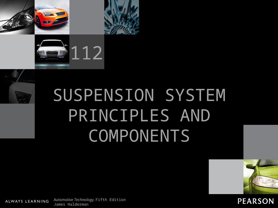
Figure 112-1 A typical truck frame is an excellent example of a ladder-type frame. The two side members are connected by a crossmember.
112 SUSPENSION SYSTEM PRINCIPLES AND COMPONENTS
Automotive Technology, Fifth EditionJames Halderman
© 2011 Pearson Education, Inc.All Rights Reserved
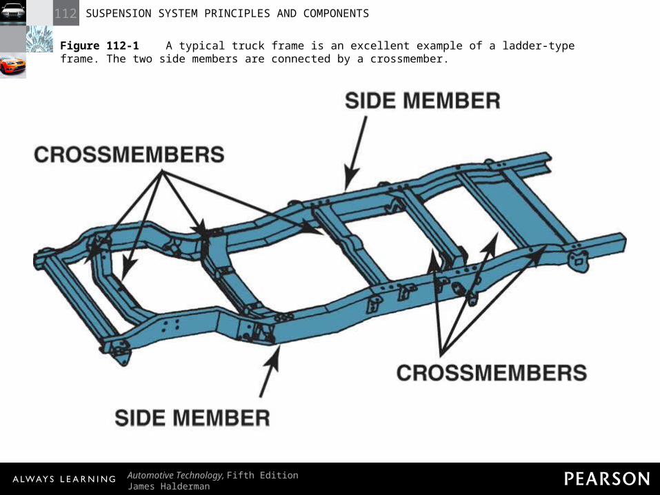
Figure 112-2 Rubber cushions used in body or frame construction isolate noise and vibration from traveling to the passenger compartment.
112 SUSPENSION SYSTEM PRINCIPLES AND COMPONENTS
Automotive Technology, Fifth EditionJames Halderman
© 2011 Pearson Education, Inc.All Rights Reserved
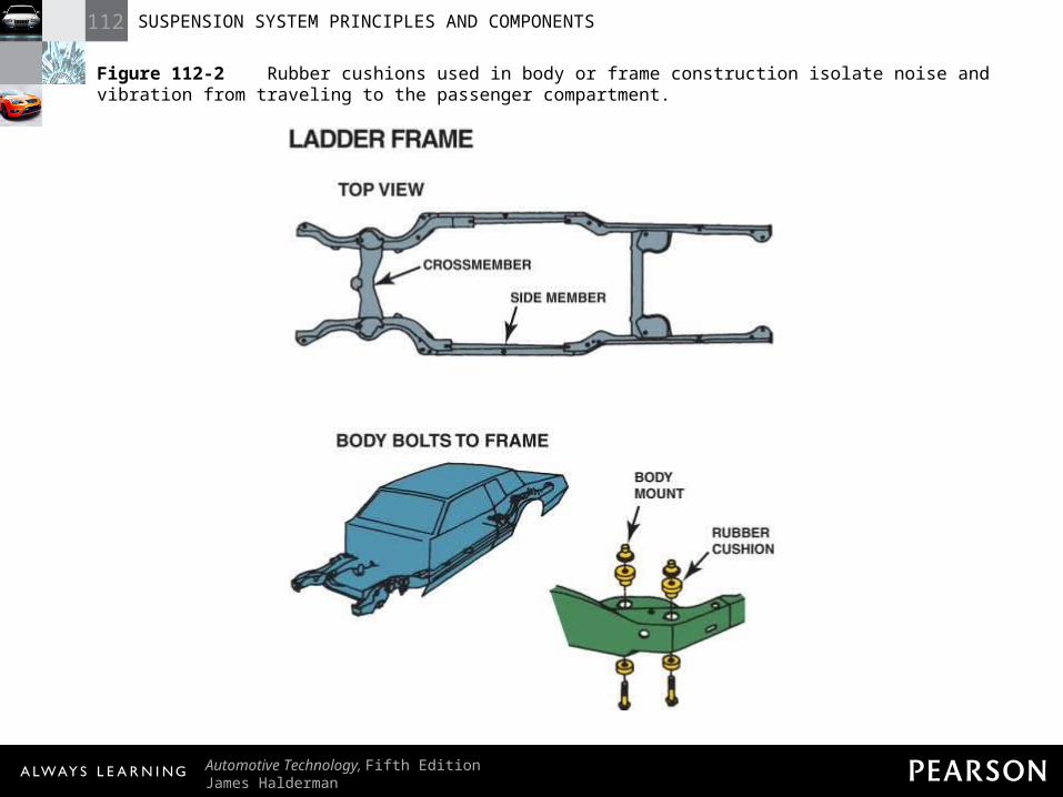
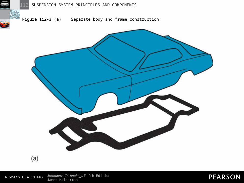
Figure 112-3 (a) Separate body and frame construction;
112 SUSPENSION SYSTEM PRINCIPLES AND COMPONENTS
Automotive Technology, Fifth EditionJames Halderman
© 2011 Pearson Education, Inc.All Rights Reserved
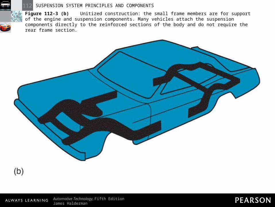
Figure 112-3 (b) Unitized construction: the small frame members are for support of the engine and suspension components. Many vehicles attach the suspension components directly to the reinforced sections of the body and do not require the rear frame section.
112 SUSPENSION SYSTEM PRINCIPLES AND COMPONENTS
Automotive Technology, Fifth EditionJames Halderman
© 2011 Pearson Education, Inc.All Rights Reserved
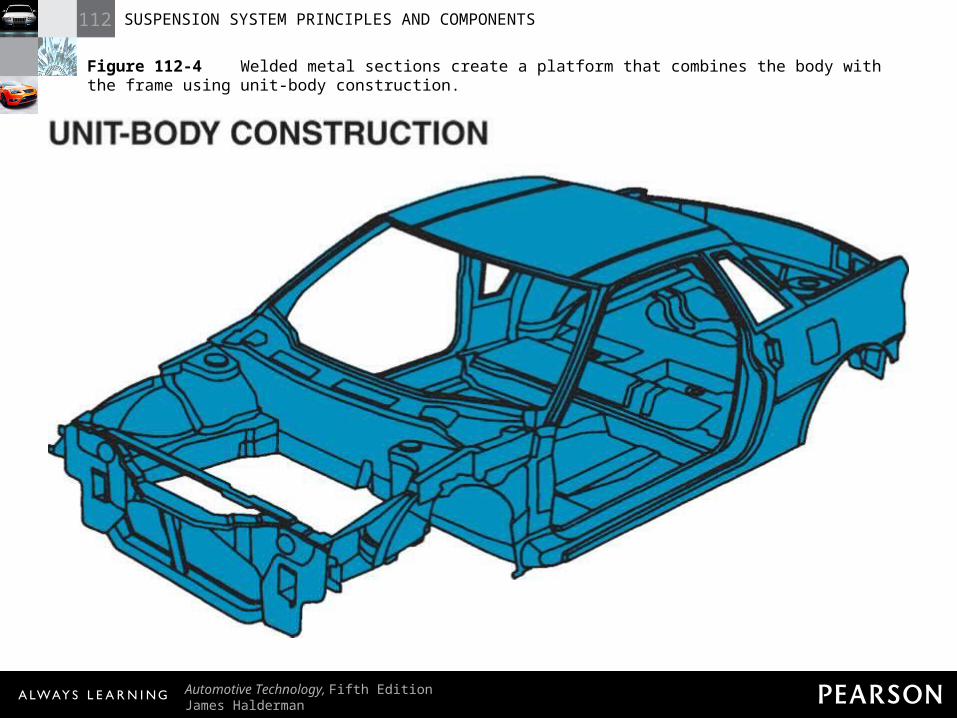
Figure 112-4 Welded metal sections create a platform that combines the body with the frame using unit-body construction.
112 SUSPENSION SYSTEM PRINCIPLES AND COMPONENTS
Automotive Technology, Fifth EditionJames Halderman
© 2011 Pearson Education, Inc.All Rights Reserved
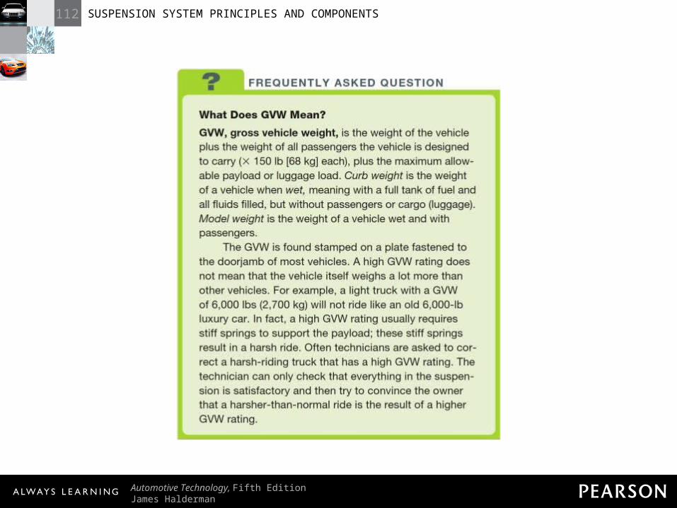
FREQUENTLY ASKED QUESTION: What Does GVW Mean? GVW, gross vehicle weight, is the weight of the vehicle plus the weight of all passengers the vehicle is designed to carry (X 150 lb [68 kg] each), plus the maximum allowable payload or luggage load. Curb weight is the weight of a vehicle when wet, meaning with a full tank of fuel and all fluids filled, but without passengers or cargo (luggage). Model weight is the weight of a vehicle wet and with passengers. The GVW is found stamped on a plate fastened to the doorjamb of most vehicles. A high GVW rating does not mean that the vehicle itself weighs a lot more than other vehicles. For example, a light truck with a GVW of 6,000 lbs (2,700 kg) will not ride like an old 6,000-lb luxury car. In fact, a high GVW rating usually requires stiff springs to support the payload; these stiff springs result in a harsh ride. Often technicians are asked to correct a harsh-riding truck that has a high GVW rating. The technician can only check that everything in the suspension is satisfactory and then try to convince the owner that a harsher-than-normal ride is the result of a higher GVW rating.
112 SUSPENSION SYSTEM PRINCIPLES AND COMPONENTS
Automotive Technology, Fifth EditionJames Halderman
© 2011 Pearson Education, Inc.All Rights Reserved
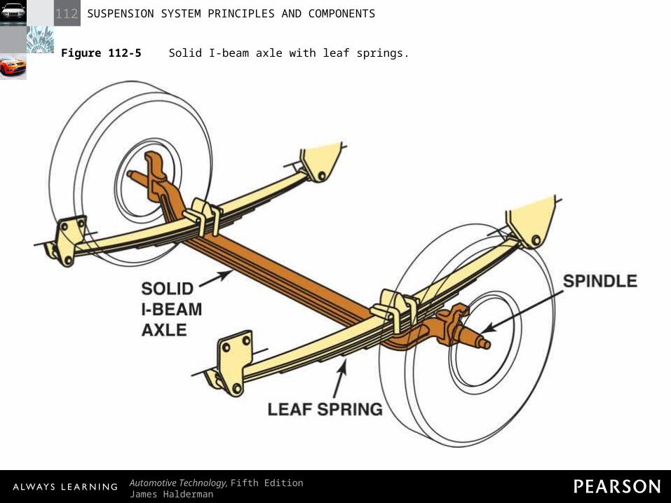
Figure 112-5 Solid I-beam axle with leaf springs.
112 SUSPENSION SYSTEM PRINCIPLES AND COMPONENTS
Automotive Technology, Fifth EditionJames Halderman
© 2011 Pearson Education, Inc.All Rights Reserved
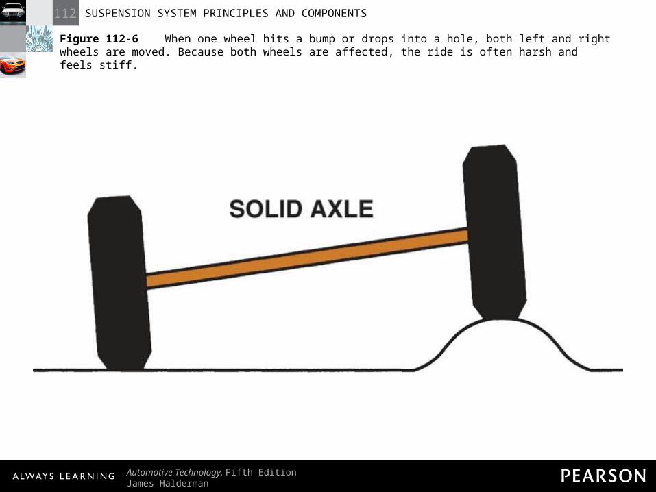
Figure 112-6 When one wheel hits a bump or drops into a hole, both left and right wheels are moved. Because both wheels are affected, the ride is often harsh and feels stiff.
112 SUSPENSION SYSTEM PRINCIPLES AND COMPONENTS
Automotive Technology, Fifth EditionJames Halderman
© 2011 Pearson Education, Inc.All Rights Reserved
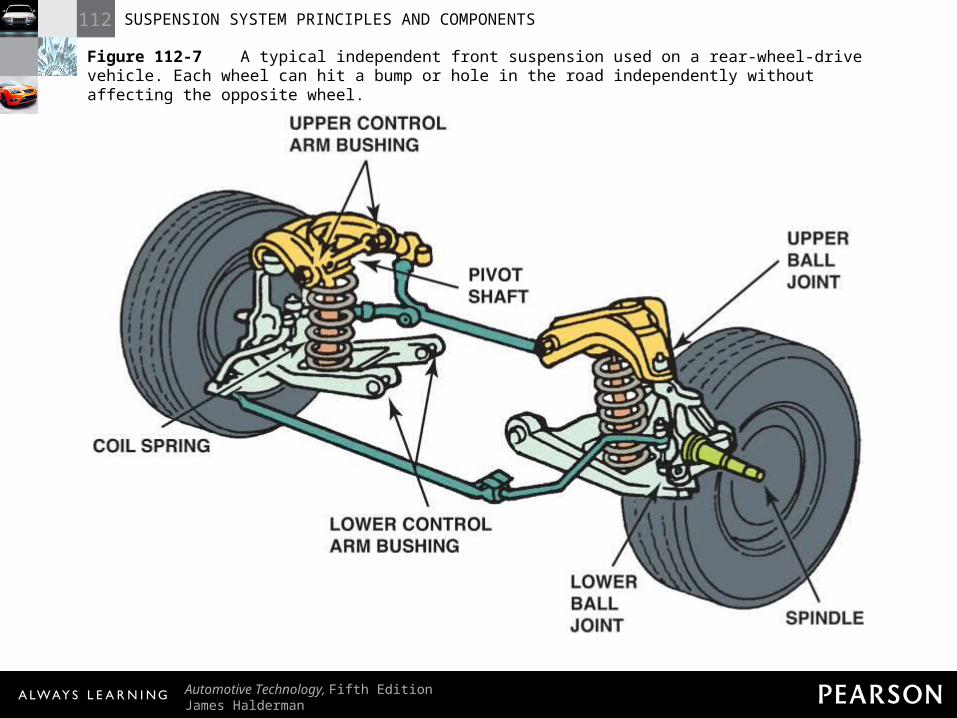
Figure 112-7 A typical independent front suspension used on a rear-wheel-drive vehicle. Each wheel can hit a bump or hole in the road independently without affecting the opposite wheel.
112 SUSPENSION SYSTEM PRINCIPLES AND COMPONENTS
Automotive Technology, Fifth EditionJames Halderman
© 2011 Pearson Education, Inc.All Rights Reserved
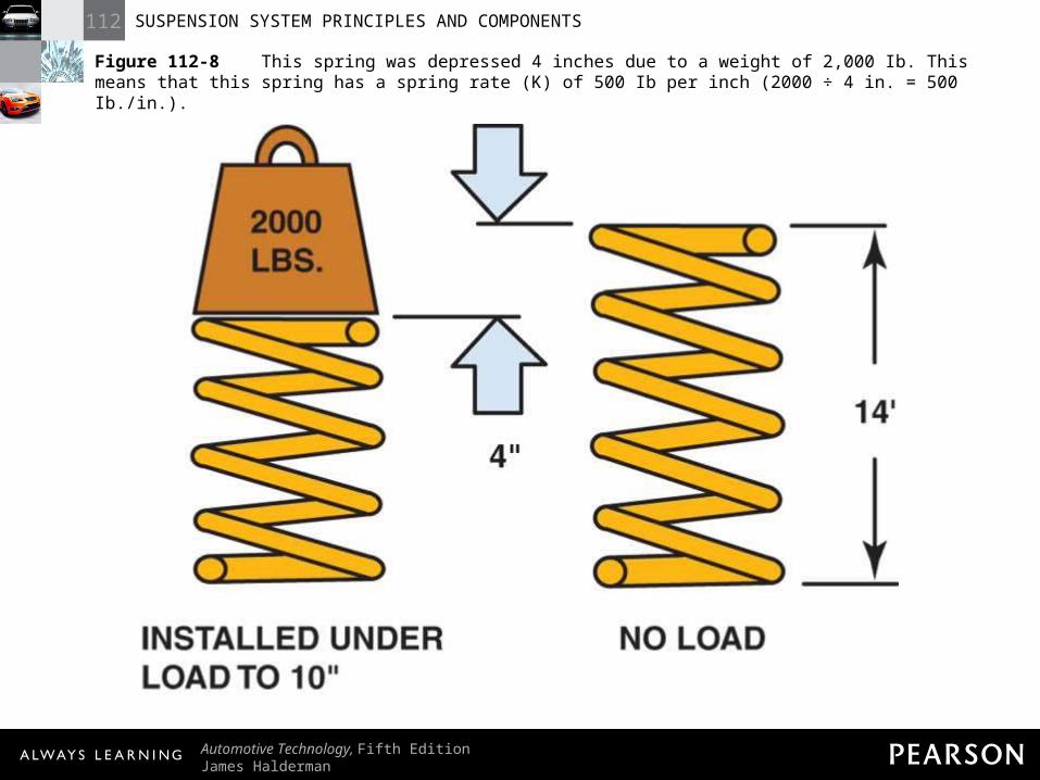
Figure 112-8 This spring was depressed 4 inches due to a weight of 2,000 Ib. This means that this spring has a spring rate (K) of 500 Ib per inch (2000 ÷ 4 in. = 500 Ib./in.).
112 SUSPENSION SYSTEM PRINCIPLES AND COMPONENTS
Automotive Technology, Fifth EditionJames Halderman
© 2011 Pearson Education, Inc.All Rights Reserved
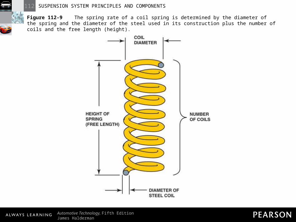
Figure 112-9 The spring rate of a coil spring is determined by the diameter of the spring and the diameter of the steel used in its construction plus the number of coils and the free length (height).
112 SUSPENSION SYSTEM PRINCIPLES AND COMPONENTS
Automotive Technology, Fifth EditionJames Halderman
© 2011 Pearson Education, Inc.All Rights Reserved
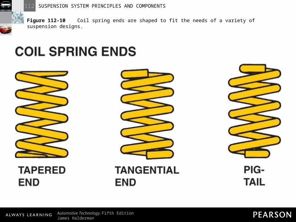
Figure 112-10 Coil spring ends are shaped to fit the needs of a variety of suspension designs.
112 SUSPENSION SYSTEM PRINCIPLES AND COMPONENTS
Automotive Technology, Fifth EditionJames Halderman
© 2011 Pearson Education, Inc.All Rights Reserved
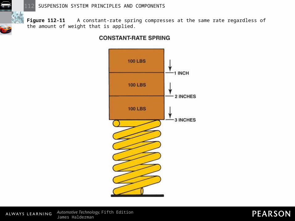
Figure 112-11 A constant-rate spring compresses at the same rate regardless of the amount of weight that is applied.
112 SUSPENSION SYSTEM PRINCIPLES AND COMPONENTS
Automotive Technology, Fifth EditionJames Halderman
© 2011 Pearson Education, Inc.All Rights Reserved
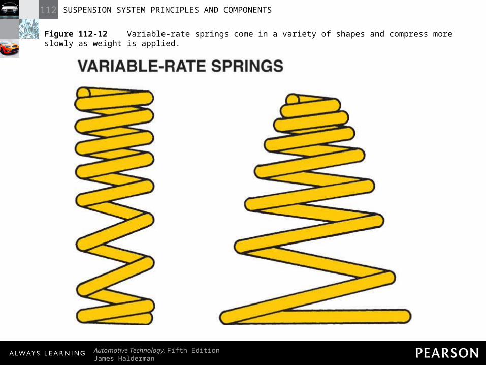
Figure 112-12 Variable-rate springs come in a variety of shapes and compress more slowly as weight is applied.
112 SUSPENSION SYSTEM PRINCIPLES AND COMPONENTS
Automotive Technology, Fifth EditionJames Halderman
© 2011 Pearson Education, Inc.All Rights Reserved
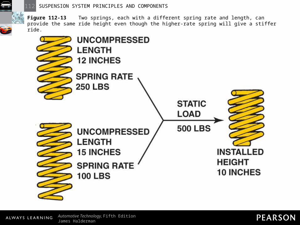
Figure 112-13 Two springs, each with a different spring rate and length, can provide the same ride height even though the higher-rate spring will give a stiffer ride.
112 SUSPENSION SYSTEM PRINCIPLES AND COMPONENTS
Automotive Technology, Fifth EditionJames Halderman
© 2011 Pearson Education, Inc.All Rights Reserved
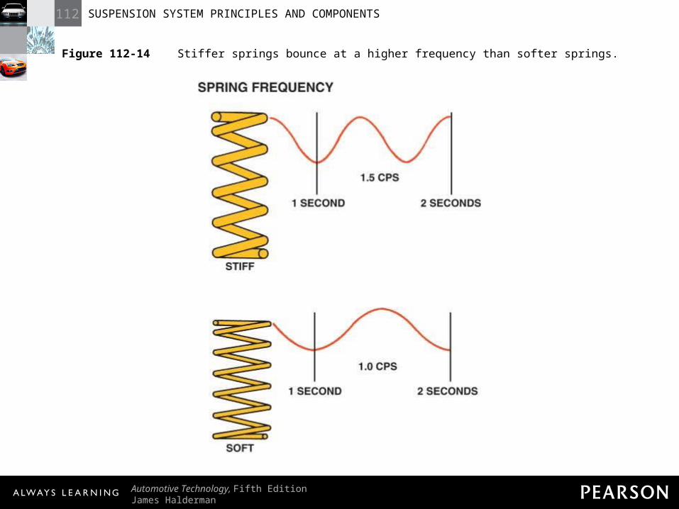
Figure 112-14 Stiffer springs bounce at a higher frequency than softer springs.
112 SUSPENSION SYSTEM PRINCIPLES AND COMPONENTS
Automotive Technology, Fifth EditionJames Halderman
© 2011 Pearson Education, Inc.All Rights Reserved
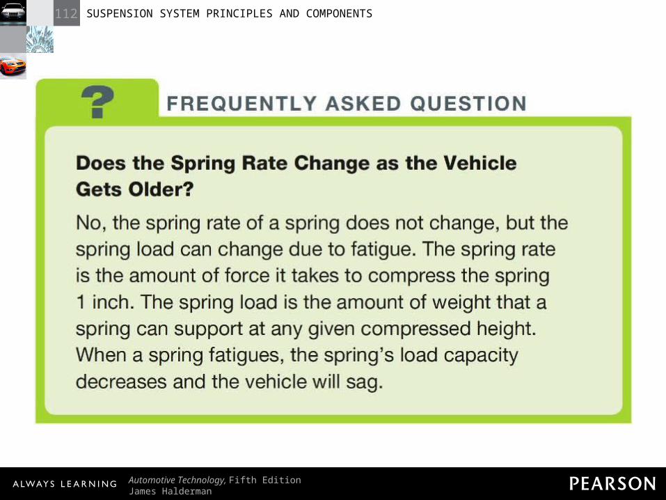
FREQUENTLY ASKED QUESTION: Does the Spring Rate Change as the Vehicle Gets Older? No, the spring rate of a spring does not change, but the spring load can change due to fatigue. The spring rate is the amount of force it takes to compress the spring 1 inch. The spring load is the amount of weight that a spring can support at any given compressed height. When a spring fatigues, the spring’s load capacity decreases and the vehicle will sag.
112 SUSPENSION SYSTEM PRINCIPLES AND COMPONENTS
Automotive Technology, Fifth EditionJames Halderman
© 2011 Pearson Education, Inc.All Rights Reserved
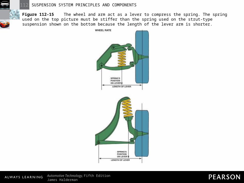
Figure 112-15 The wheel and arm act as a lever to compress the spring. The spring used on the top picture must be stiffer than the spring used on the strut-type suspension shown on the bottom because the length of the lever arm is shorter.
112 SUSPENSION SYSTEM PRINCIPLES AND COMPONENTS
Automotive Technology, Fifth EditionJames Halderman
© 2011 Pearson Education, Inc.All Rights Reserved
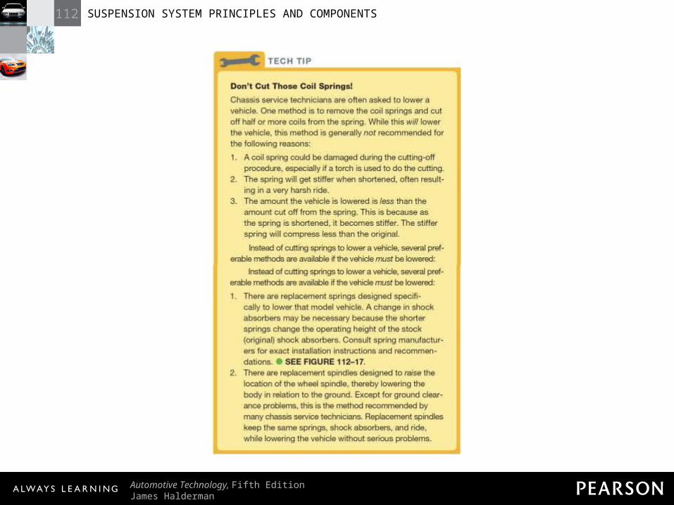
TECH TIP: Don’t Cut Those Coil Springs! Chassis service technicians are often asked to lower a vehicle. One method is to remove the coil springs and cut off half or more coils from the spring. While this will lower the vehicle, this method is generally not recommended for the following reasons: 1. A coil spring could be damaged during the cutting-off procedure, especially if a torch is used to do the cutting. 2. The spring will get stiffer when shortened, often resulting in a very harsh ride. 3. The amount the vehicle is lowered is less than the amount cut off from the spring. This is because as the spring is shortened, it becomes stiffer. The stiffer spring will compress less than the original.Instead of cutting springs to lower a vehicle, several preferable methods are available if the vehicle must be lowered: 1. There are replacement springs designed specifically to lower that model vehicle. A change in shock absorbers may be necessary because the shorter springs change the operating height of the stock (original) shock absorbers. Consult spring manufacturers for exact installation instructions and recommendations. - SEE FIGURE 112–17 . 2. There are replacement spindles designed to raise the location of the wheel spindle, thereby lowering the body in relation to the ground. Except for ground clearance problems, this is the method recommended by many chassis service technicians. Replacement spindles keep the same springs, shock absorbers, and ride, while lowering the vehicle without serious problems.
112 SUSPENSION SYSTEM PRINCIPLES AND COMPONENTS
Automotive Technology, Fifth EditionJames Halderman
© 2011 Pearson Education, Inc.All Rights Reserved
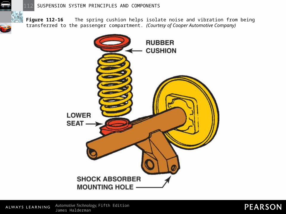
Figure 112-16 The spring cushion helps isolate noise and vibration from being transferred to the passenger compartment. (Courtesy of Cooper Automotive Company)
112 SUSPENSION SYSTEM PRINCIPLES AND COMPONENTS
Automotive Technology, Fifth EditionJames Halderman
© 2011 Pearson Education, Inc.All Rights Reserved
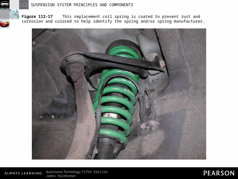
Figure 112-17 This replacement coil spring is coated to prevent rust and corrosion and colored to help identify the spring and/or spring manufacturer.
112 SUSPENSION SYSTEM PRINCIPLES AND COMPONENTS
Automotive Technology, Fifth EditionJames Halderman
© 2011 Pearson Education, Inc.All Rights Reserved
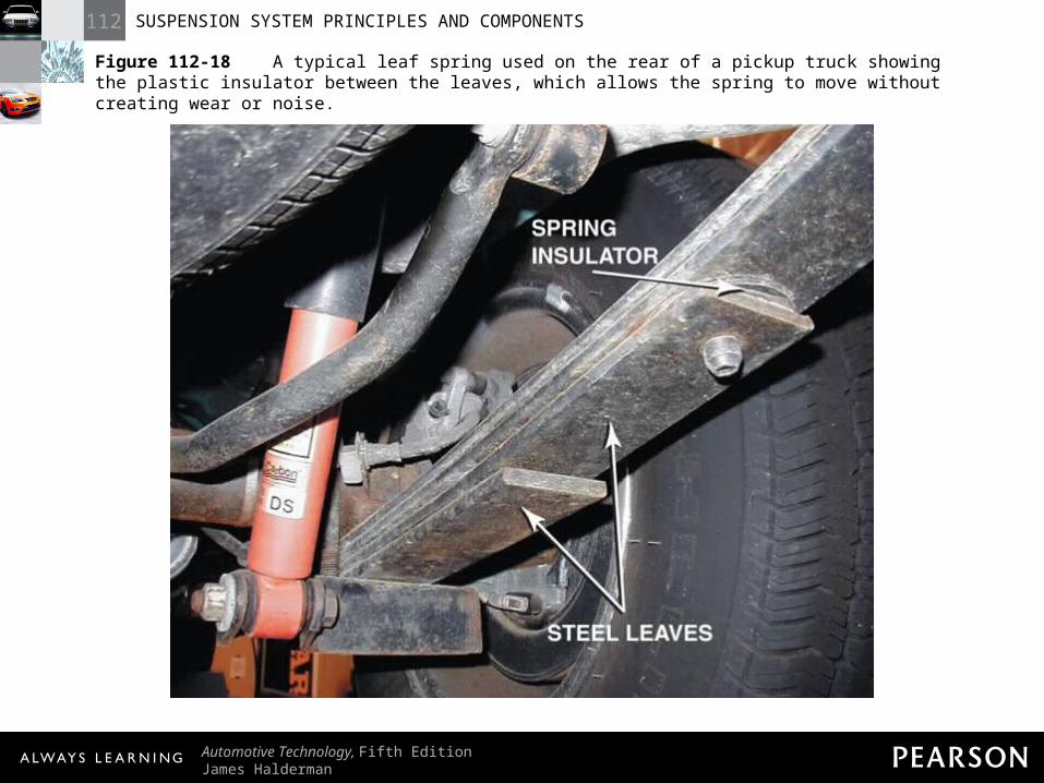
Figure 112-18 A typical leaf spring used on the rear of a pickup truck showing the plastic insulator between the leaves, which allows the spring to move without creating wear or noise.
112 SUSPENSION SYSTEM PRINCIPLES AND COMPONENTS
Automotive Technology, Fifth EditionJames Halderman
© 2011 Pearson Education, Inc.All Rights Reserved
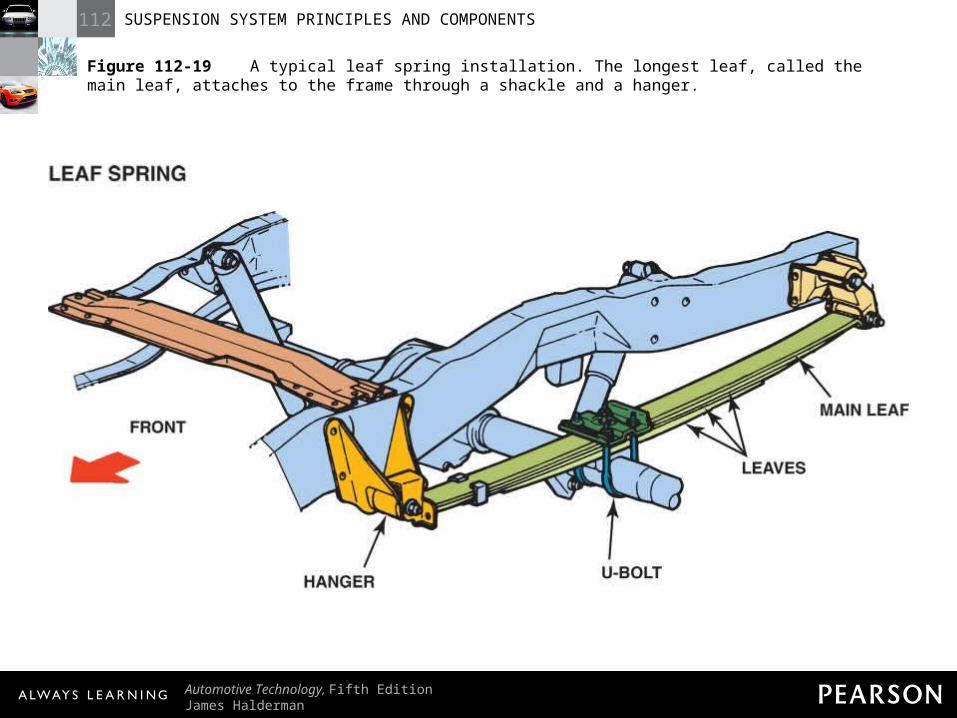
Figure 112-19 A typical leaf spring installation. The longest leaf, called the main leaf, attaches to the frame through a shackle and a hanger.
112 SUSPENSION SYSTEM PRINCIPLES AND COMPONENTS
Automotive Technology, Fifth EditionJames Halderman
© 2011 Pearson Education, Inc.All Rights Reserved
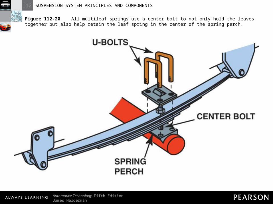
Figure 112-20 All multileaf springs use a center bolt to not only hold the leaves together but also help retain the leaf spring in the center of the spring perch.
112 SUSPENSION SYSTEM PRINCIPLES AND COMPONENTS
Automotive Technology, Fifth EditionJames Halderman
© 2011 Pearson Education, Inc.All Rights Reserved
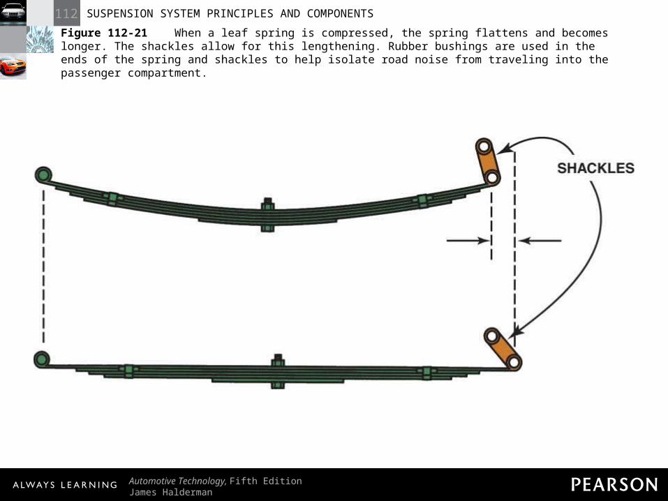
Figure 112-21 When a leaf spring is compressed, the spring flattens and becomes longer. The shackles allow for this lengthening. Rubber bushings are used in the ends of the spring and shackles to help isolate road noise from traveling into the passenger compartment.
112 SUSPENSION SYSTEM PRINCIPLES AND COMPONENTS
Automotive Technology, Fifth EditionJames Halderman
© 2011 Pearson Education, Inc.All Rights Reserved
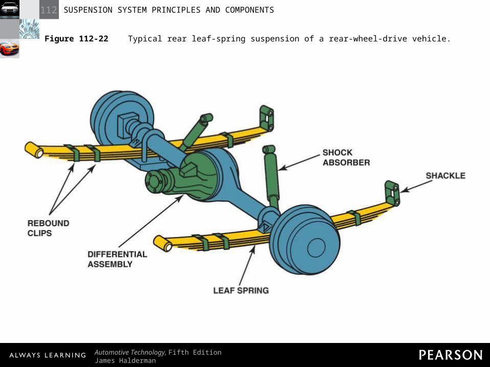
Figure 112-22 Typical rear leaf-spring suspension of a rear-wheel-drive vehicle.
112 SUSPENSION SYSTEM PRINCIPLES AND COMPONENTS
Automotive Technology, Fifth EditionJames Halderman
© 2011 Pearson Education, Inc.All Rights Reserved
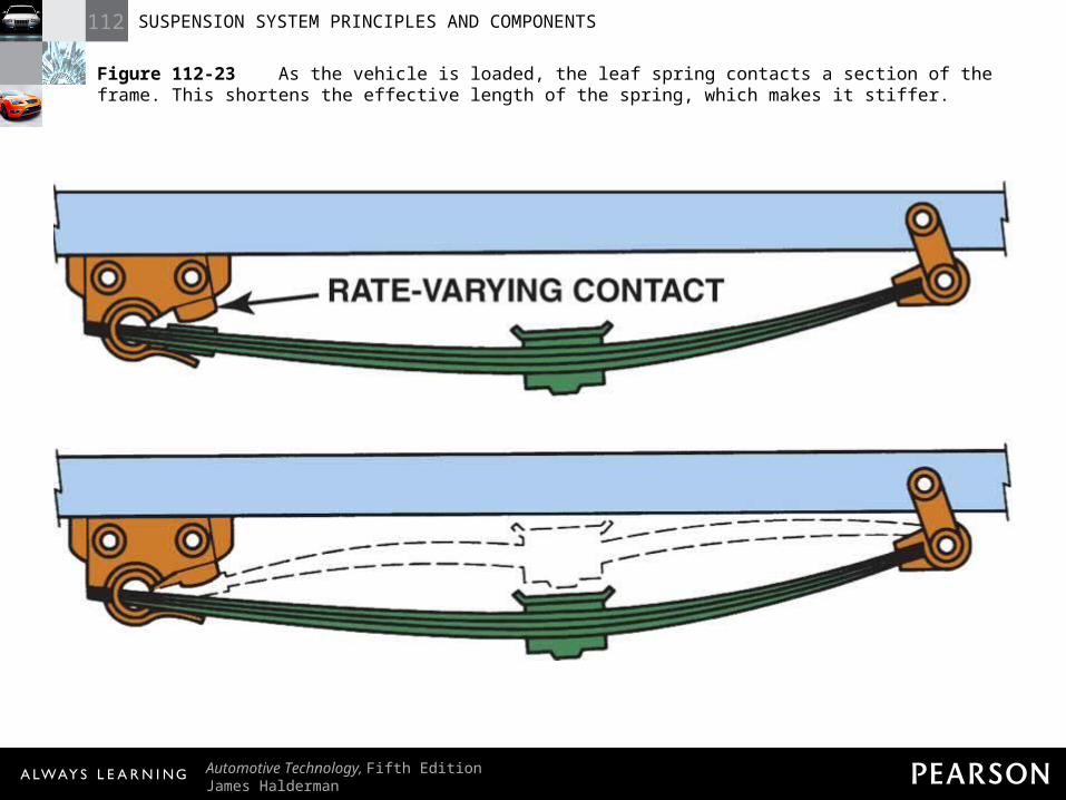
Figure 112-23 As the vehicle is loaded, the leaf spring contacts a section of the frame. This shortens the effective length of the spring, which makes it stiffer.
112 SUSPENSION SYSTEM PRINCIPLES AND COMPONENTS
Automotive Technology, Fifth EditionJames Halderman
© 2011 Pearson Education, Inc.All Rights Reserved
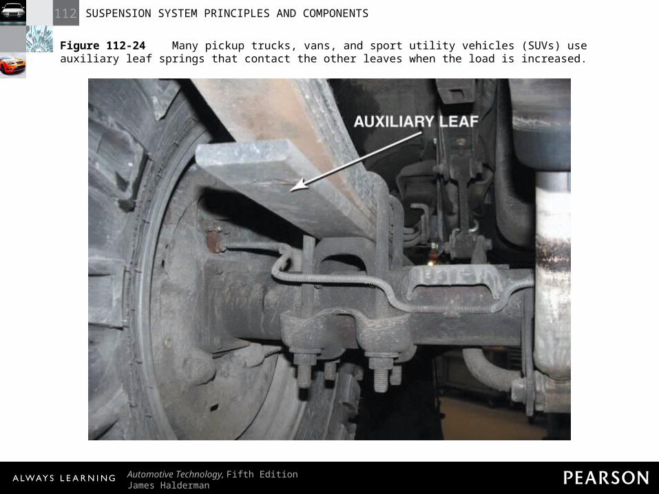
Figure 112-24 Many pickup trucks, vans, and sport utility vehicles (SUVs) use auxiliary leaf springs that contact the other leaves when the load is increased.
112 SUSPENSION SYSTEM PRINCIPLES AND COMPONENTS
Automotive Technology, Fifth EditionJames Halderman
© 2011 Pearson Education, Inc.All Rights Reserved
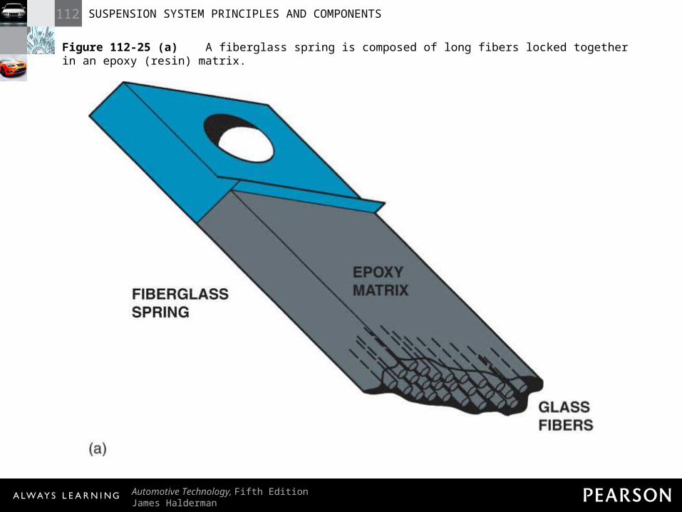
Figure 112-25 (a) A fiberglass spring is composed of long fibers locked together in an epoxy (resin) matrix.
112 SUSPENSION SYSTEM PRINCIPLES AND COMPONENTS
Automotive Technology, Fifth EditionJames Halderman
© 2011 Pearson Education, Inc.All Rights Reserved
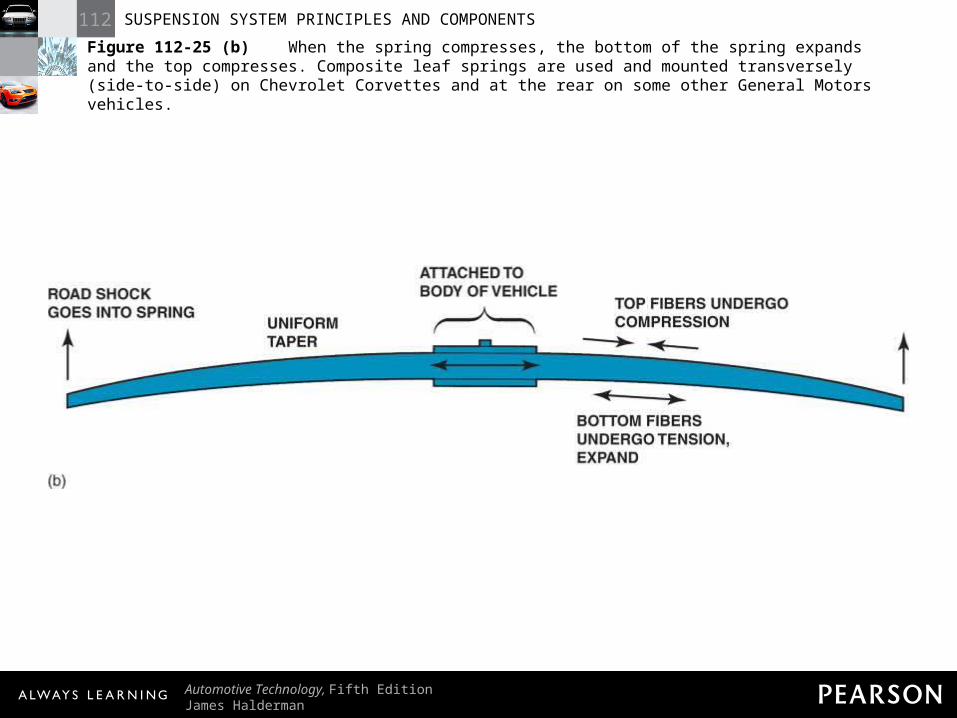
Figure 112-25 (b) When the spring compresses, the bottom of the spring expands and the top compresses. Composite leaf springs are used and mounted transversely (side-to-side) on Chevrolet Corvettes and at the rear on some other General Motors vehicles.
112 SUSPENSION SYSTEM PRINCIPLES AND COMPONENTS
Automotive Technology, Fifth EditionJames Halderman
© 2011 Pearson Education, Inc.All Rights Reserved
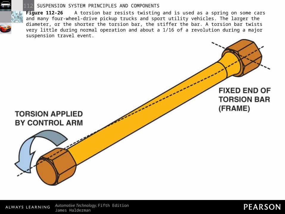
Figure 112-26 A torsion bar resists twisting and is used as a spring on some cars and many four-wheel-drive pickup trucks and sport utility vehicles. The larger the diameter, or the shorter the torsion bar, the stiffer the bar. A torsion bar twists very little during normal operation and about a 1/16 of a revolution during a major suspension travel event.
112 SUSPENSION SYSTEM PRINCIPLES AND COMPONENTS
Automotive Technology, Fifth EditionJames Halderman
© 2011 Pearson Education, Inc.All Rights Reserved
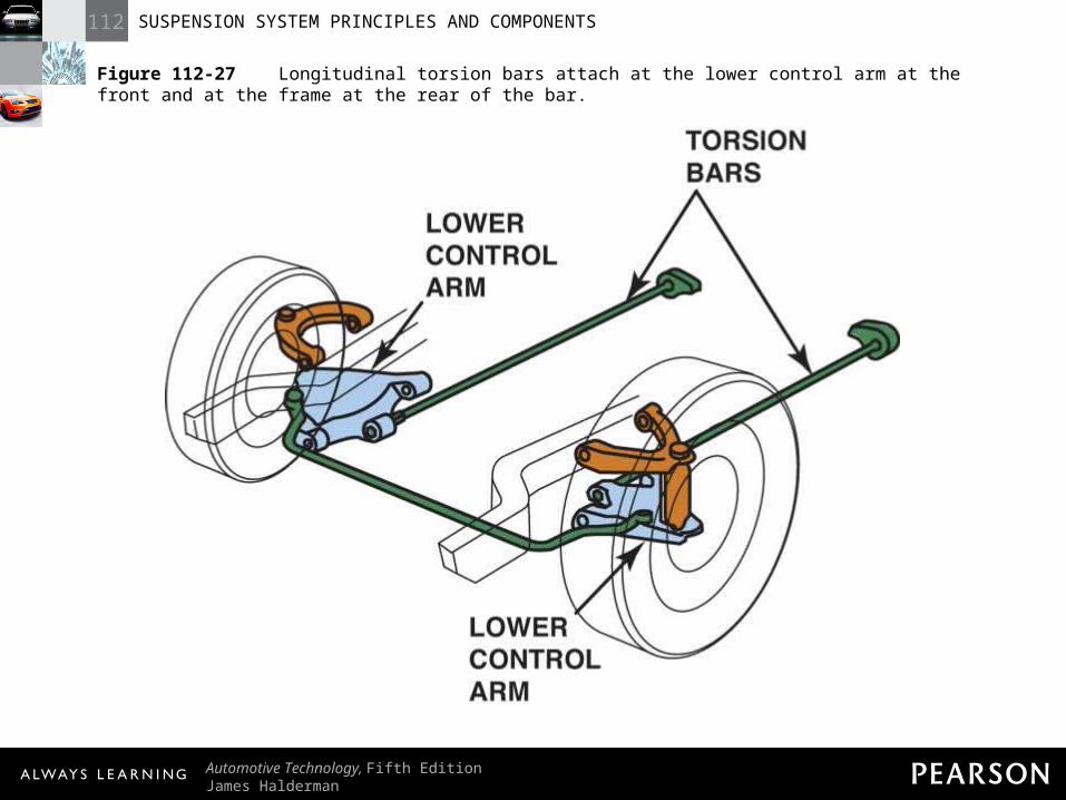
Figure 112-27 Longitudinal torsion bars attach at the lower control arm at the front and at the frame at the rear of the bar.
112 SUSPENSION SYSTEM PRINCIPLES AND COMPONENTS
Automotive Technology, Fifth EditionJames Halderman
© 2011 Pearson Education, Inc.All Rights Reserved
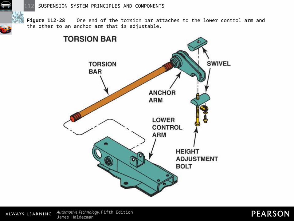
Figure 112-28 One end of the torsion bar attaches to the lower control arm and the other to an anchor arm that is adjustable.
112 SUSPENSION SYSTEM PRINCIPLES AND COMPONENTS
Automotive Technology, Fifth EditionJames Halderman
© 2011 Pearson Education, Inc.All Rights Reserved
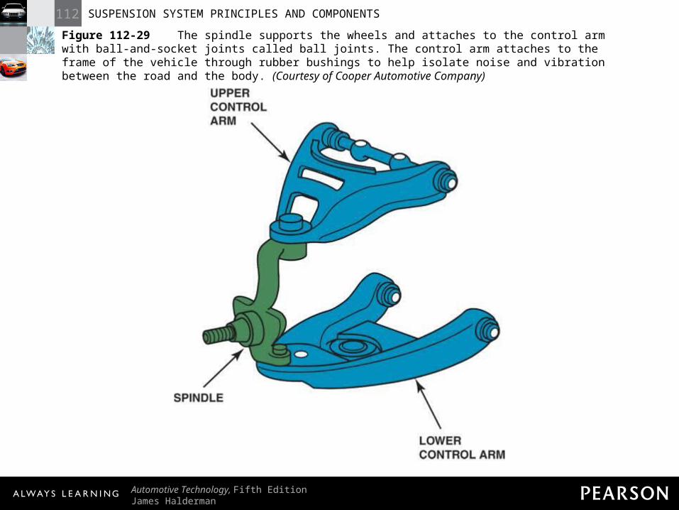
Figure 112-29 The spindle supports the wheels and attaches to the control arm with ball-and-socket joints called ball joints. The control arm attaches to the frame of the vehicle through rubber bushings to help isolate noise and vibration between the road and the body. (Courtesy of Cooper Automotive Company)
112 SUSPENSION SYSTEM PRINCIPLES AND COMPONENTS
Automotive Technology, Fifth EditionJames Halderman
© 2011 Pearson Education, Inc.All Rights Reserved
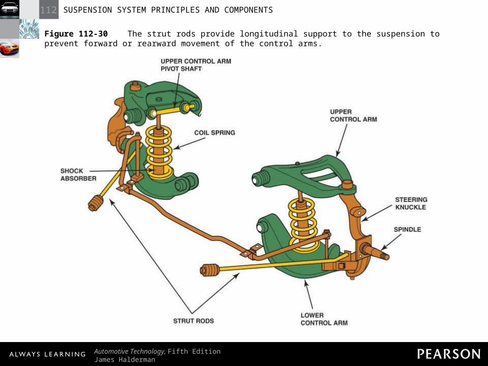
Figure 112-30 The strut rods provide longitudinal support to the suspension to prevent forward or rearward movement of the control arms.
112 SUSPENSION SYSTEM PRINCIPLES AND COMPONENTS
Automotive Technology, Fifth EditionJames Halderman
© 2011 Pearson Education, Inc.All Rights Reserved
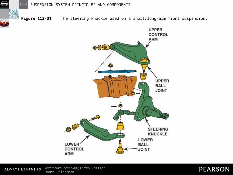
Figure 112-31 The steering knuckle used on a short/long-arm front suspension.
112 SUSPENSION SYSTEM PRINCIPLES AND COMPONENTS
Automotive Technology, Fifth EditionJames Halderman
© 2011 Pearson Education, Inc.All Rights Reserved
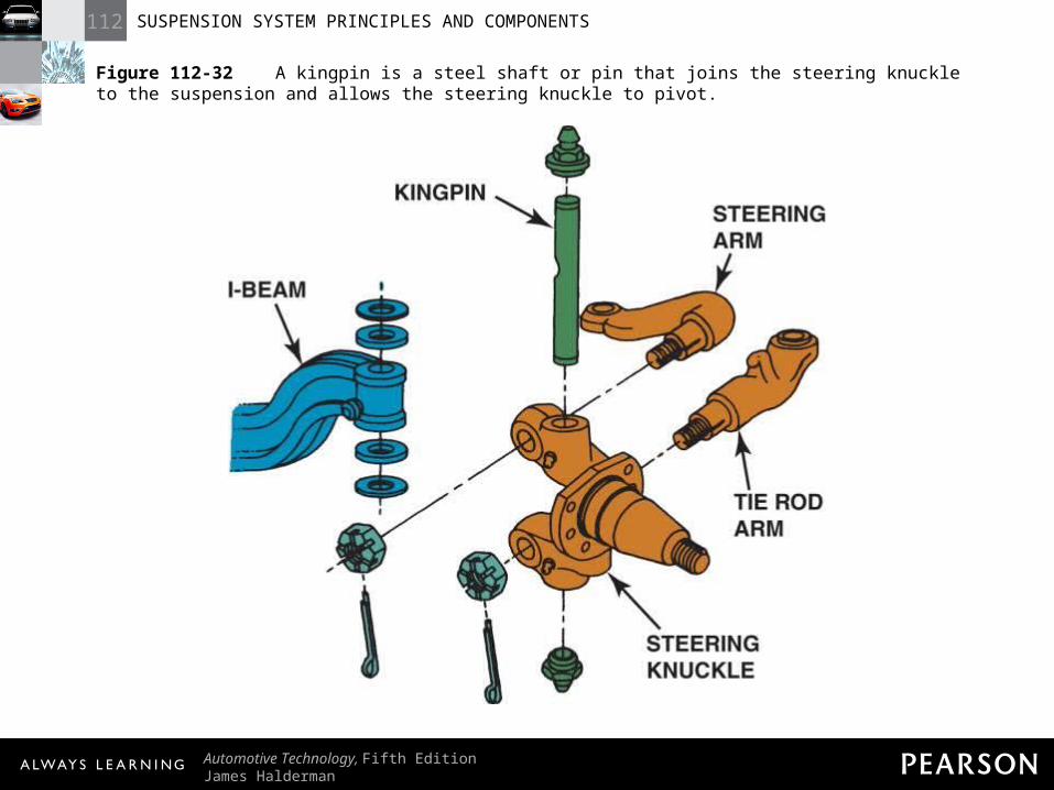
Figure 112-32 A kingpin is a steel shaft or pin that joins the steering knuckle to the suspension and allows the steering knuckle to pivot.
112 SUSPENSION SYSTEM PRINCIPLES AND COMPONENTS
Automotive Technology, Fifth EditionJames Halderman
© 2011 Pearson Education, Inc.All Rights Reserved
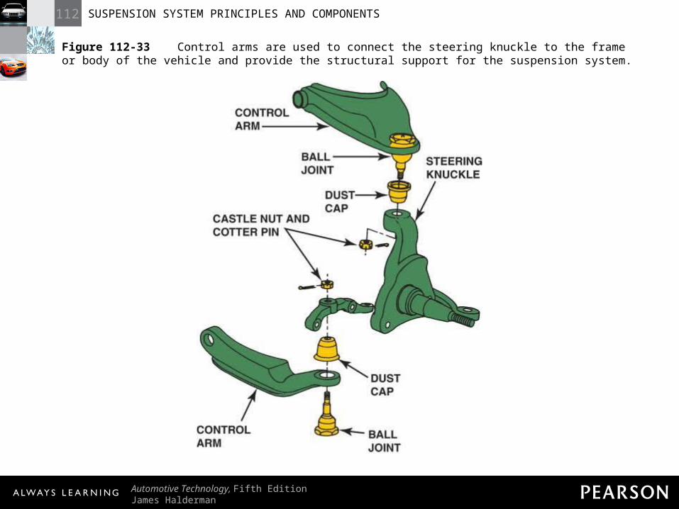
Figure 112-33 Control arms are used to connect the steering knuckle to the frame or body of the vehicle and provide the structural support for the suspension system.
112 SUSPENSION SYSTEM PRINCIPLES AND COMPONENTS
Automotive Technology, Fifth EditionJames Halderman
© 2011 Pearson Education, Inc.All Rights Reserved
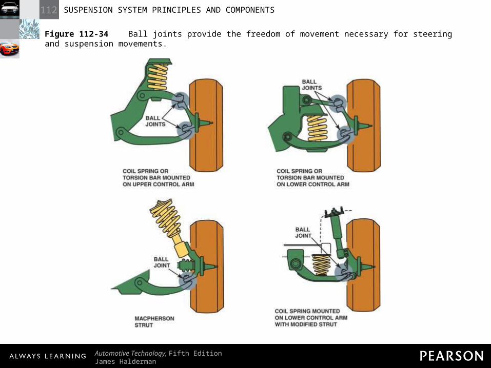
Figure 112-34 Ball joints provide the freedom of movement necessary for steering and suspension movements.
112 SUSPENSION SYSTEM PRINCIPLES AND COMPONENTS
Automotive Technology, Fifth EditionJames Halderman
© 2011 Pearson Education, Inc.All Rights Reserved
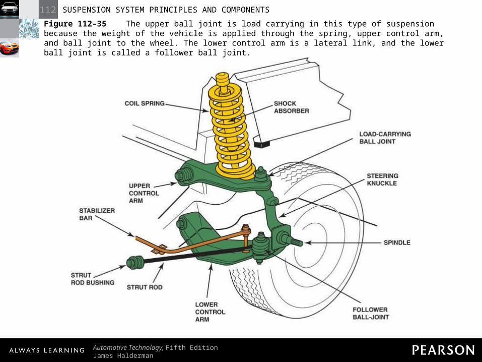
Figure 112-35 The upper ball joint is load carrying in this type of suspension because the weight of the vehicle is applied through the spring, upper control arm, and ball joint to the wheel. The lower control arm is a lateral link, and the lower ball joint is called a follower ball joint.
112 SUSPENSION SYSTEM PRINCIPLES AND COMPONENTS
Automotive Technology, Fifth EditionJames Halderman
© 2011 Pearson Education, Inc.All Rights Reserved
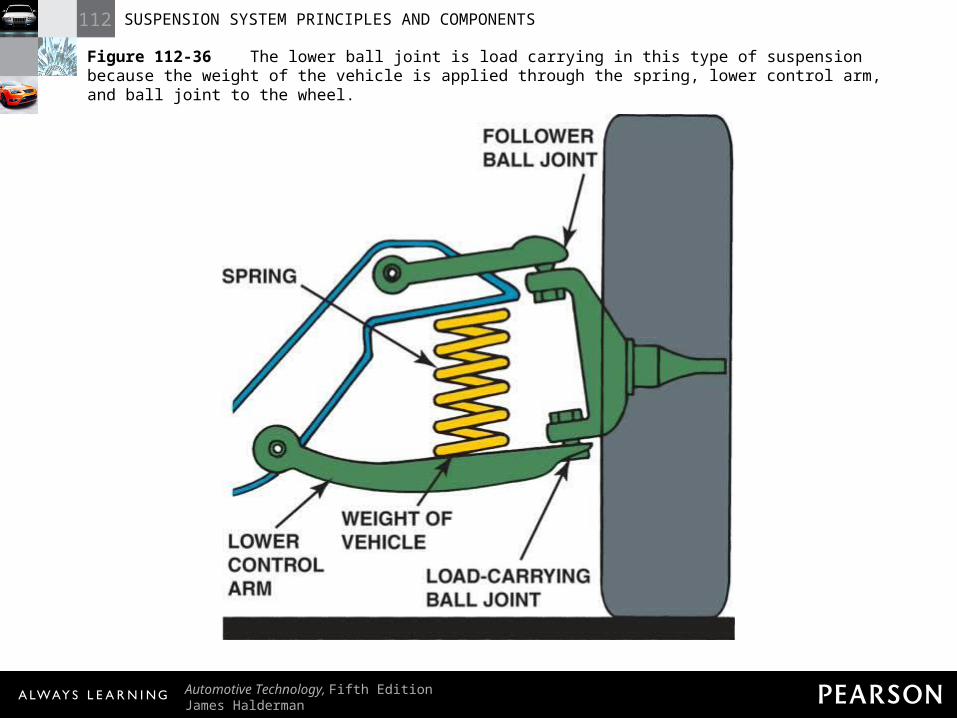
Figure 112-36 The lower ball joint is load carrying in this type of suspension because the weight of the vehicle is applied through the spring, lower control arm, and ball joint to the wheel.
112 SUSPENSION SYSTEM PRINCIPLES AND COMPONENTS
Automotive Technology, Fifth EditionJames Halderman
© 2011 Pearson Education, Inc.All Rights Reserved
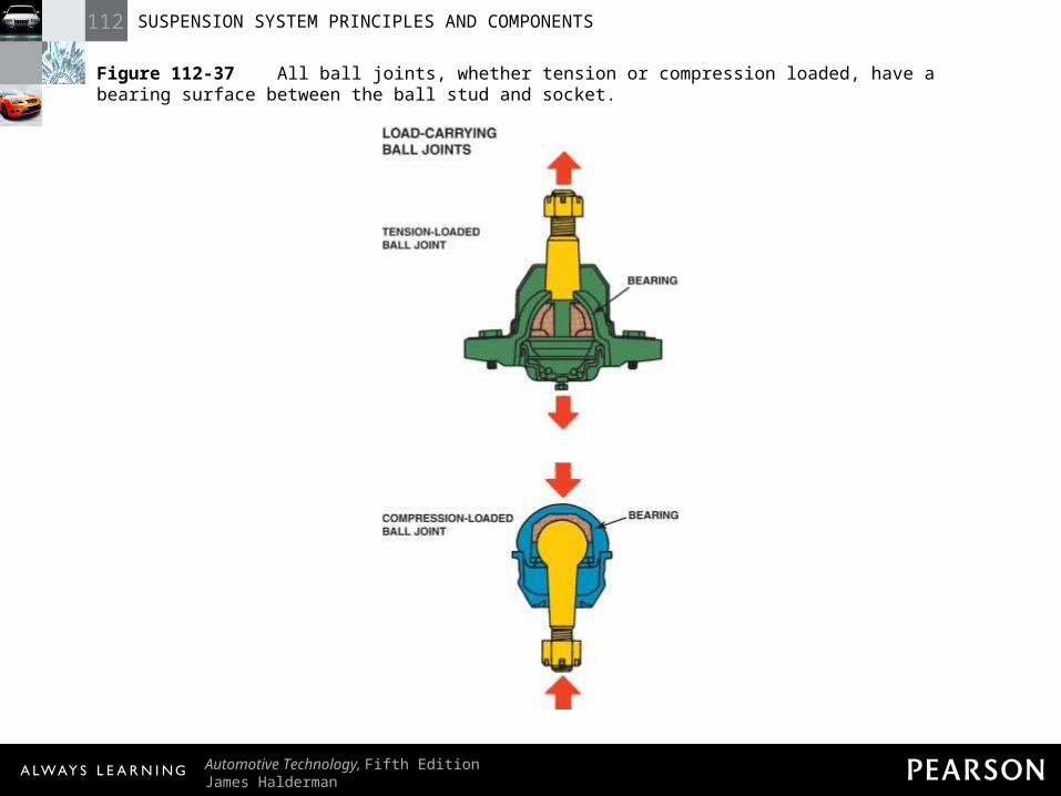
Figure 112-37 All ball joints, whether tension or compression loaded, have a bearing surface between the ball stud and socket.
112 SUSPENSION SYSTEM PRINCIPLES AND COMPONENTS
Automotive Technology, Fifth EditionJames Halderman
© 2011 Pearson Education, Inc.All Rights Reserved
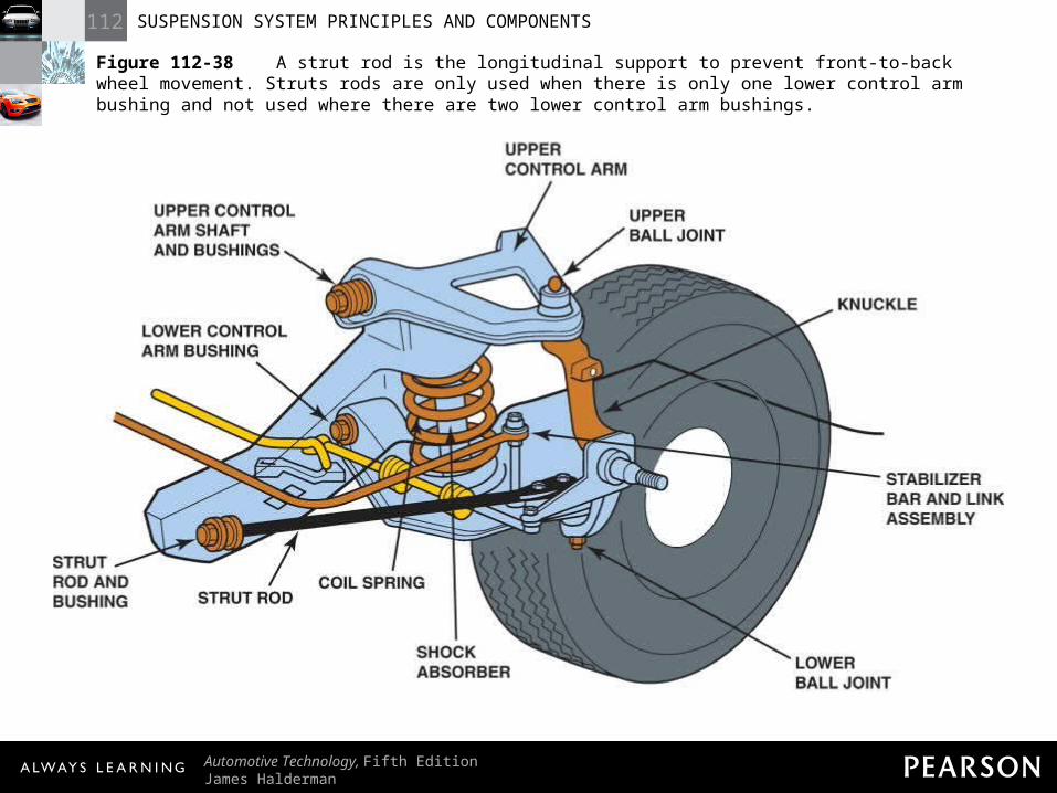
Figure 112-38 A strut rod is the longitudinal support to prevent front-to-back wheel movement. Struts rods are only used when there is only one lower control arm bushing and not used where there are two lower control arm bushings.
112 SUSPENSION SYSTEM PRINCIPLES AND COMPONENTS
Automotive Technology, Fifth EditionJames Halderman
© 2011 Pearson Education, Inc.All Rights Reserved
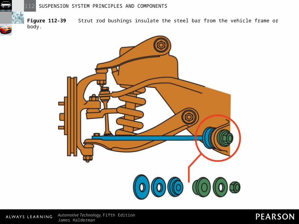
Figure 112-39 Strut rod bushings insulate the steel bar from the vehicle frame or body.
112 SUSPENSION SYSTEM PRINCIPLES AND COMPONENTS
Automotive Technology, Fifth EditionJames Halderman
© 2011 Pearson Education, Inc.All Rights Reserved
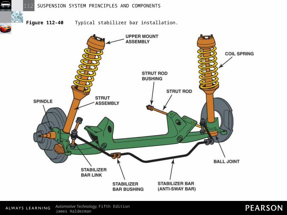
Figure 112-40 Typical stabilizer bar installation.
112 SUSPENSION SYSTEM PRINCIPLES AND COMPONENTS
Automotive Technology, Fifth EditionJames Halderman
© 2011 Pearson Education, Inc.All Rights Reserved
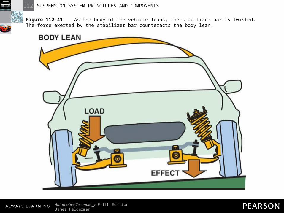
Figure 112-41 As the body of the vehicle leans, the stabilizer bar is twisted. The force exerted by the stabilizer bar counteracts the body lean.
112 SUSPENSION SYSTEM PRINCIPLES AND COMPONENTS
Automotive Technology, Fifth EditionJames Halderman
© 2011 Pearson Education, Inc.All Rights Reserved
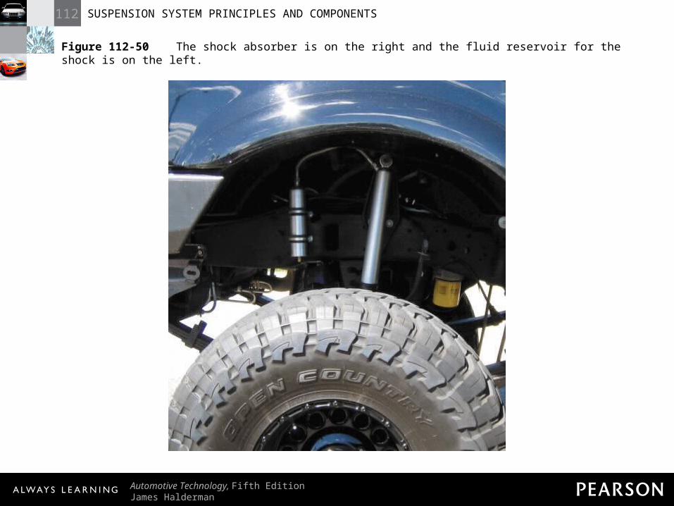
FREQUENTLY ASKED QUESTION: What Are Remote Reservoir Shocks? Remote reservoir shock absorbers are units designed for heavy-duty use that use a separate container for the working fluid. - SEE FIGURE 112–50 on page 1308. The purpose of the remote fluid reservoir is to keep the temperature of the fluid stable, which helps the shock absorber provide consistent dampening under all conditions.
112 SUSPENSION SYSTEM PRINCIPLES AND COMPONENTS
Automotive Technology, Fifth EditionJames Halderman
© 2011 Pearson Education, Inc.All Rights Reserved
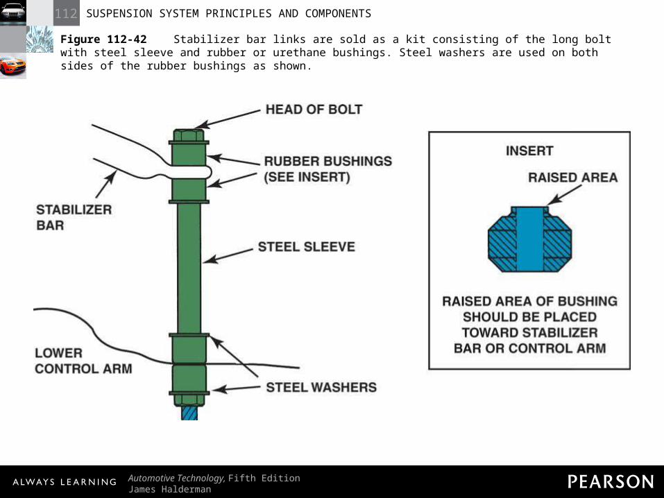
Figure 112-42 Stabilizer bar links are sold as a kit consisting of the long bolt with steel sleeve and rubber or urethane bushings. Steel washers are used on both sides of the rubber bushings as shown.
112 SUSPENSION SYSTEM PRINCIPLES AND COMPONENTS
Automotive Technology, Fifth EditionJames Halderman
© 2011 Pearson Education, Inc.All Rights Reserved
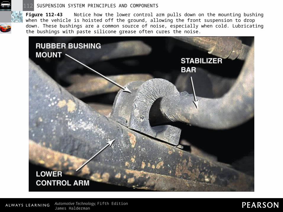
Figure 112-43 Notice how the lower control arm pulls down on the mounting bushing when the vehicle is hoisted off the ground, allowing the front suspension to drop down. These bushings are a common source of noise, especially when cold. Lubricating the bushings with paste silicone grease often cures the noise.
112 SUSPENSION SYSTEM PRINCIPLES AND COMPONENTS
Automotive Technology, Fifth EditionJames Halderman
© 2011 Pearson Education, Inc.All Rights Reserved
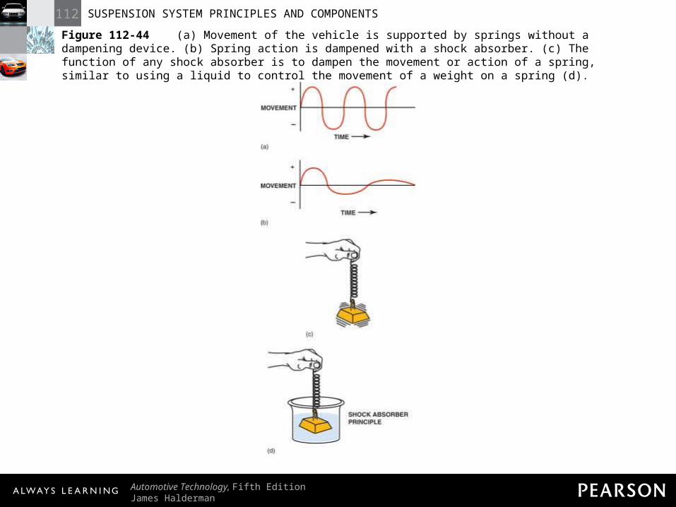
Figure 112-44 (a) Movement of the vehicle is supported by springs without a dampening device. (b) Spring action is dampened with a shock absorber. (c) The function of any shock absorber is to dampen the movement or action of a spring, similar to using a liquid to control the movement of a weight on a spring (d).
112 SUSPENSION SYSTEM PRINCIPLES AND COMPONENTS
Automotive Technology, Fifth EditionJames Halderman
© 2011 Pearson Education, Inc.All Rights Reserved
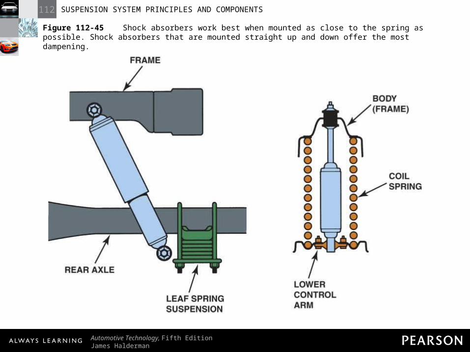
Figure 112-45 Shock absorbers work best when mounted as close to the spring as possible. Shock absorbers that are mounted straight up and down offer the most dampening.
112 SUSPENSION SYSTEM PRINCIPLES AND COMPONENTS
Automotive Technology, Fifth EditionJames Halderman
© 2011 Pearson Education, Inc.All Rights Reserved
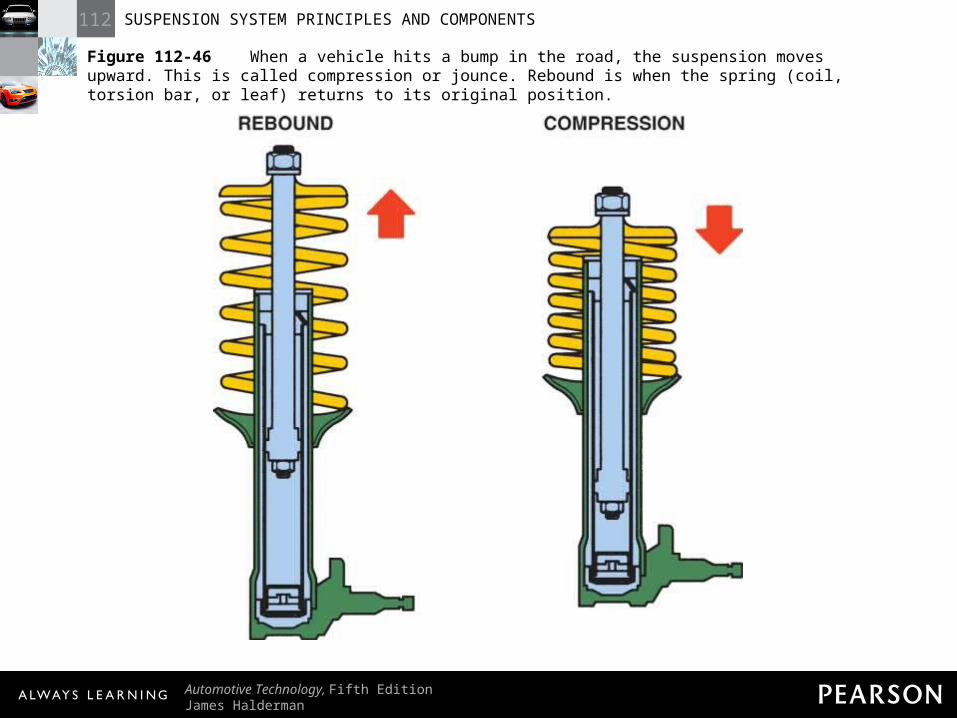
Figure 112-46 When a vehicle hits a bump in the road, the suspension moves upward. This is called compression or jounce. Rebound is when the spring (coil, torsion bar, or leaf) returns to its original position.
112 SUSPENSION SYSTEM PRINCIPLES AND COMPONENTS
Automotive Technology, Fifth EditionJames Halderman
© 2011 Pearson Education, Inc.All Rights Reserved
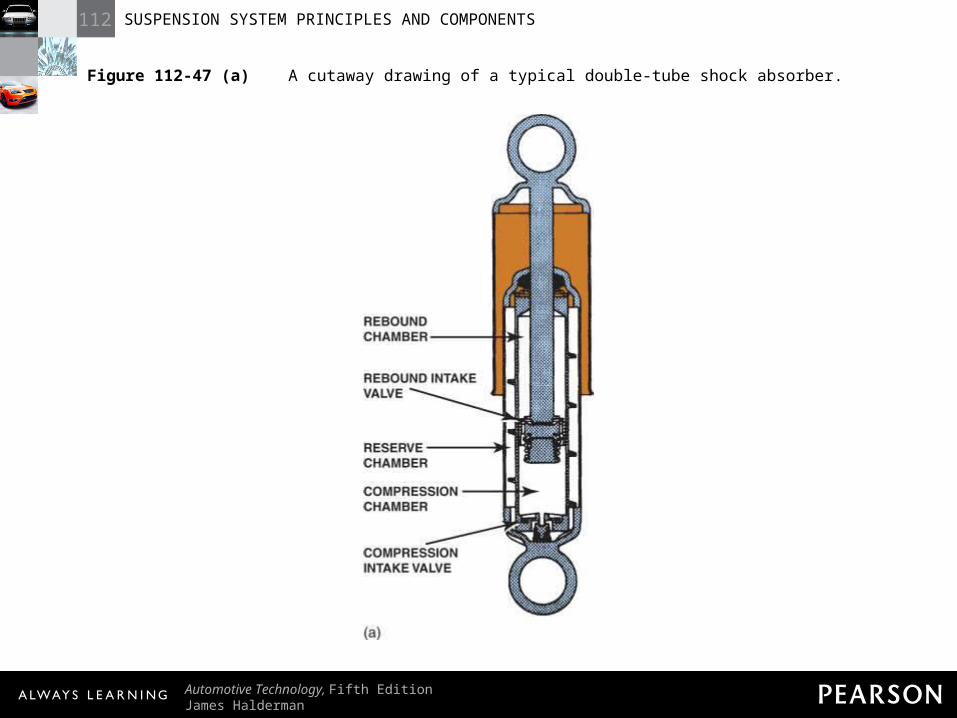
Figure 112-47 (a) A cutaway drawing of a typical double-tube shock absorber.
112 SUSPENSION SYSTEM PRINCIPLES AND COMPONENTS
Automotive Technology, Fifth EditionJames Halderman
© 2011 Pearson Education, Inc.All Rights Reserved
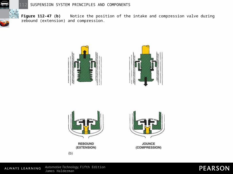
Figure 112-47 (b) Notice the position of the intake and compression valve during rebound (extension) and compression.
112 SUSPENSION SYSTEM PRINCIPLES AND COMPONENTS
Automotive Technology, Fifth EditionJames Halderman
© 2011 Pearson Education, Inc.All Rights Reserved
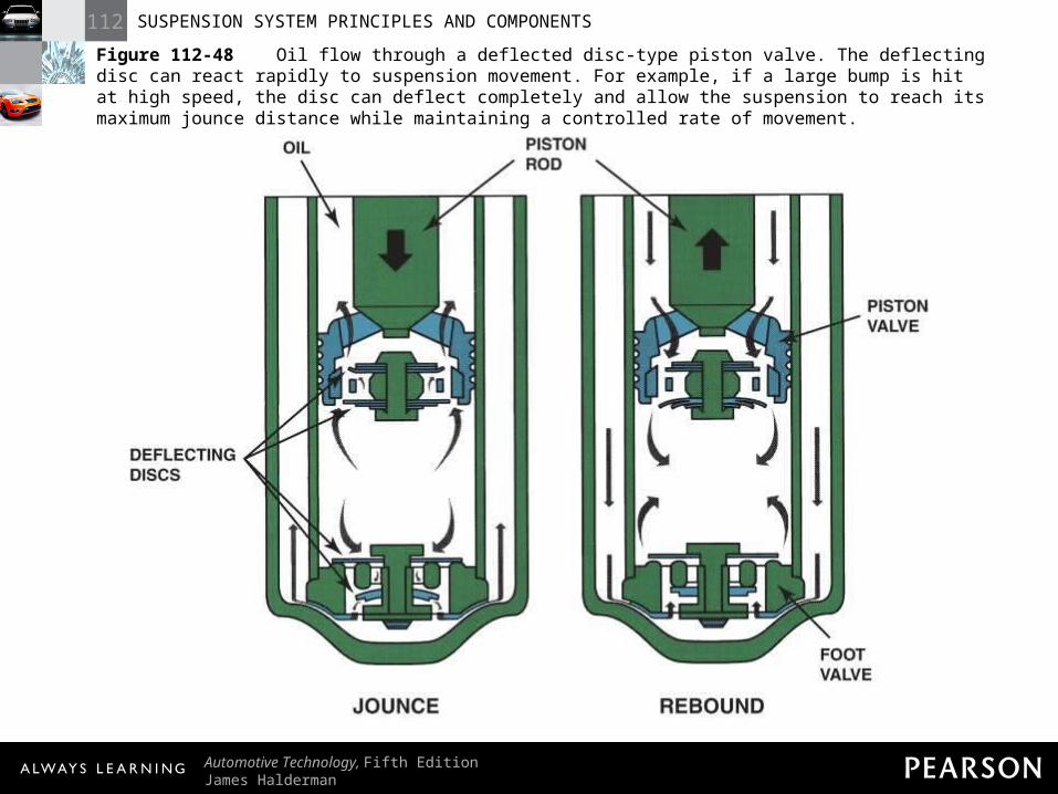
Figure 112-48 Oil flow through a deflected disc-type piston valve. The deflecting disc can react rapidly to suspension movement. For example, if a large bump is hit at high speed, the disc can deflect completely and allow the suspension to reach its maximum jounce distance while maintaining a controlled rate of movement.
112 SUSPENSION SYSTEM PRINCIPLES AND COMPONENTS
Automotive Technology, Fifth EditionJames Halderman
© 2011 Pearson Education, Inc.All Rights Reserved
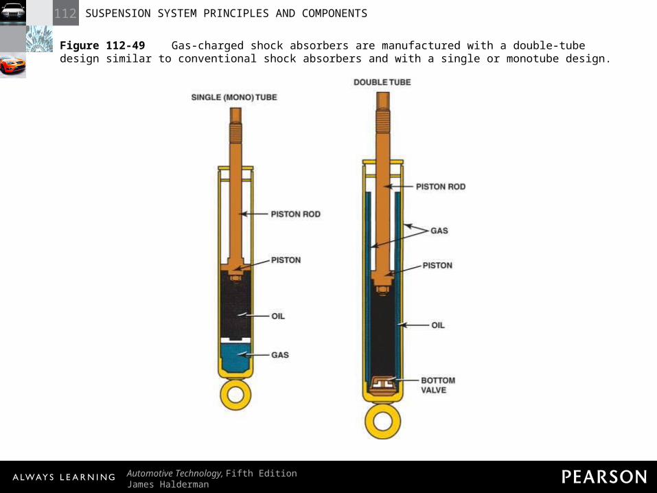
Figure 112-49 Gas-charged shock absorbers are manufactured with a double-tube design similar to conventional shock absorbers and with a single or monotube design.
112 SUSPENSION SYSTEM PRINCIPLES AND COMPONENTS
Automotive Technology, Fifth EditionJames Halderman
© 2011 Pearson Education, Inc.All Rights Reserved
Figure 112-50 The shock absorber is on the right and the fluid reservoir for the shock is on the left.
112 SUSPENSION SYSTEM PRINCIPLES AND COMPONENTS
Automotive Technology, Fifth EditionJames Halderman
© 2011 Pearson Education, Inc.All Rights Reserved
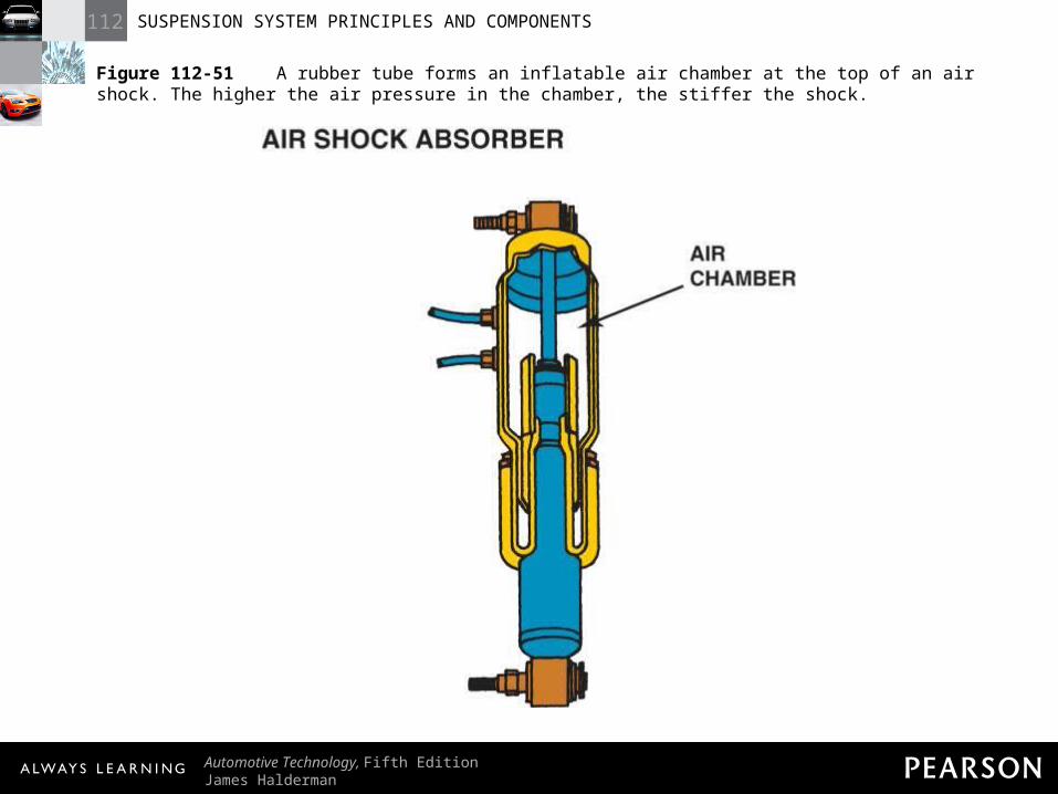
Figure 112-51 A rubber tube forms an inflatable air chamber at the top of an air shock. The higher the air pressure in the chamber, the stiffer the shock.
112 SUSPENSION SYSTEM PRINCIPLES AND COMPONENTS
Automotive Technology, Fifth EditionJames Halderman
© 2011 Pearson Education, Inc.All Rights Reserved
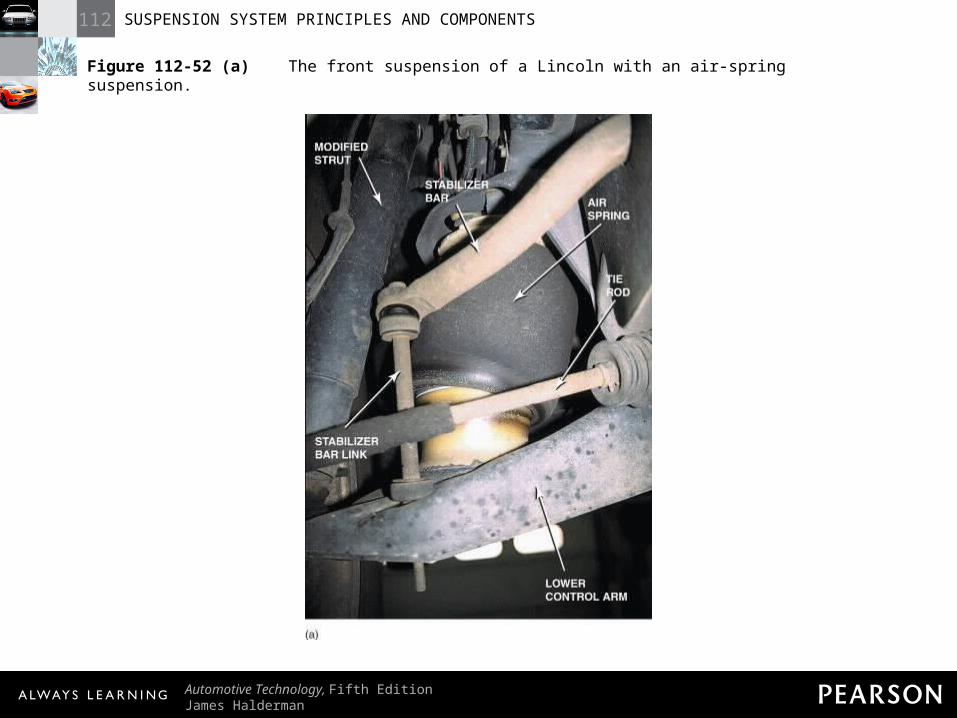
Figure 112-52 (a) The front suspension of a Lincoln with an air-spring suspension.
112 SUSPENSION SYSTEM PRINCIPLES AND COMPONENTS
Automotive Technology, Fifth EditionJames Halderman
© 2011 Pearson Education, Inc.All Rights Reserved
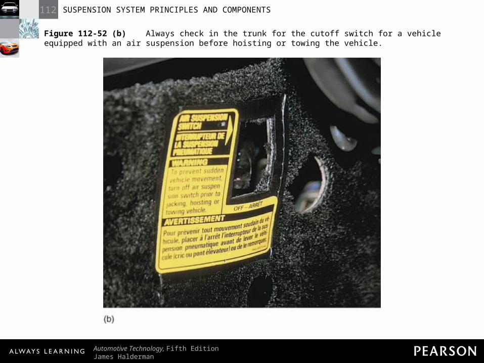
Figure 112-52 (b) Always check in the trunk for the cutoff switch for a vehicle equipped with an air suspension before hoisting or towing the vehicle.
112 SUSPENSION SYSTEM PRINCIPLES AND COMPONENTS
Automotive Technology, Fifth EditionJames Halderman
© 2011 Pearson Education, Inc.All Rights Reserved
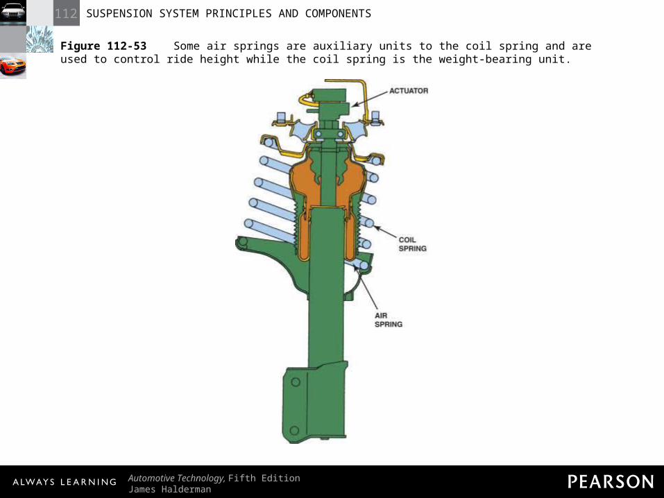
Figure 112-53 Some air springs are auxiliary units to the coil spring and are used to control ride height while the coil spring is the weight-bearing unit.
112 SUSPENSION SYSTEM PRINCIPLES AND COMPONENTS
Automotive Technology, Fifth EditionJames Halderman
© 2011 Pearson Education, Inc.All Rights Reserved
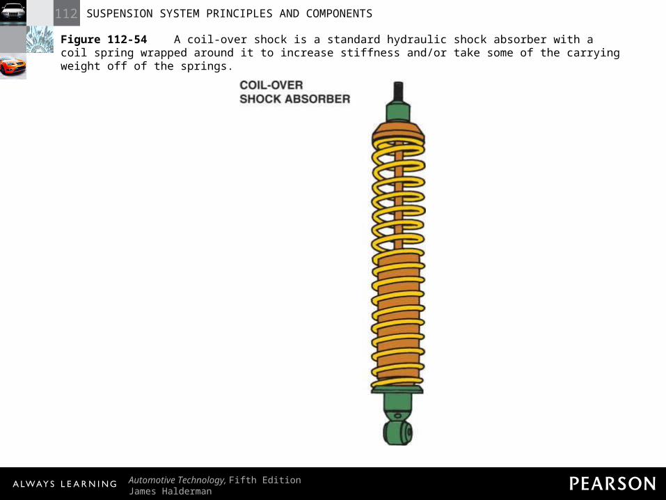
Figure 112-54 A coil-over shock is a standard hydraulic shock absorber with a coil spring wrapped around it to increase stiffness and/or take some of the carrying weight off of the springs.
112 SUSPENSION SYSTEM PRINCIPLES AND COMPONENTS
Automotive Technology, Fifth EditionJames Halderman
© 2011 Pearson Education, Inc.All Rights Reserved
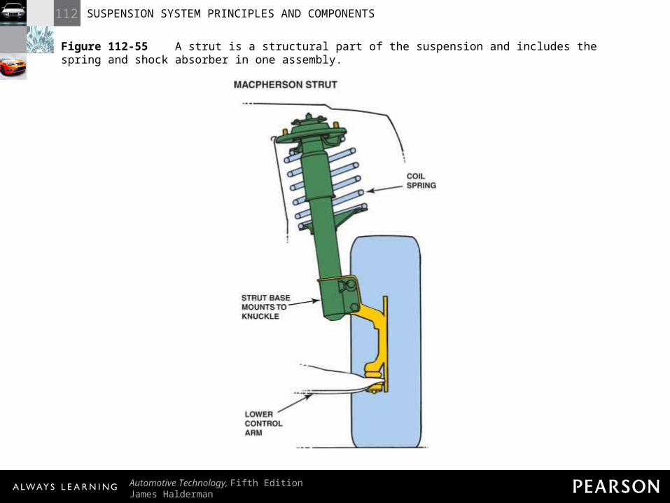
Figure 112-55 A strut is a structural part of the suspension and includes the spring and shock absorber in one assembly.
112 SUSPENSION SYSTEM PRINCIPLES AND COMPONENTS
Automotive Technology, Fifth EditionJames Halderman
© 2011 Pearson Education, Inc.All Rights Reserved
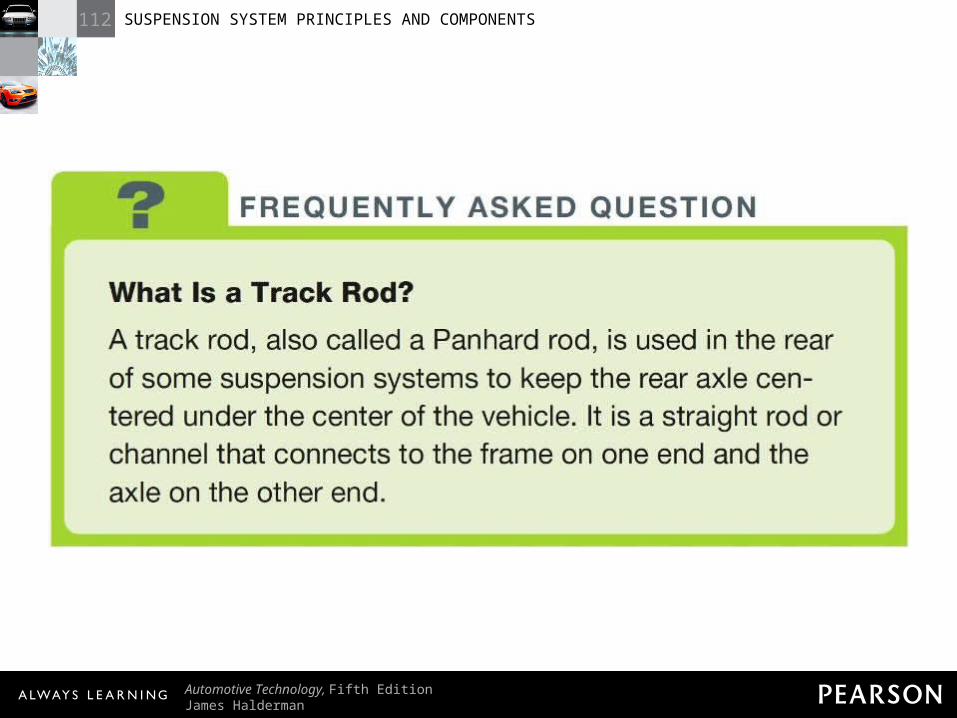
FREQUENTLY ASKED QUESTION: What Is a Track Rod? A track rod, also called a Panhard rod, is used in the rear of some suspension systems to keep the rear axle centered under the center of the vehicle. It is a straight rod or channel that connects to the frame on one end and the axle on the other end.
112 SUSPENSION SYSTEM PRINCIPLES AND COMPONENTS
Automotive Technology, Fifth EditionJames Halderman
© 2011 Pearson Education, Inc.All Rights Reserved
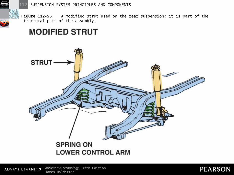
Figure 112-56 A modified strut used on the rear suspension; it is part of the structural part of the assembly.
112 SUSPENSION SYSTEM PRINCIPLES AND COMPONENTS
Automotive Technology, Fifth EditionJames Halderman
© 2011 Pearson Education, Inc.All Rights Reserved
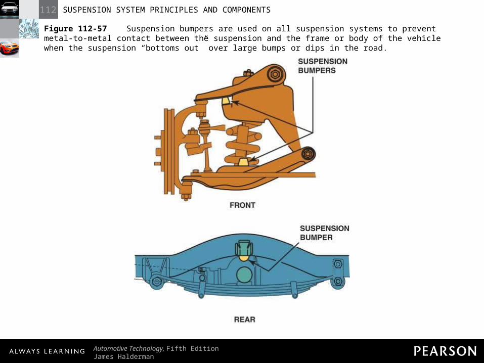
Figure 112-57 Suspension bumpers are used on all suspension systems to prevent metal-to-metal contact between the suspension and the frame or body of the vehicle when the suspension “bottoms out” over large bumps or dips in the road.