Embed Size (px)
Citation preview
SUSSMAN AUTOMATIC STEAM PRODUCTS
MANUAL FOR LEXINGTON FINISHING TUNNEL
AFTER 1976
INSTALLATION, OPERATION AND PARTS.
Lind Industries, Inc d.b.a. Lind Laundry Systems 9615 STONE AVE N SEATTLE, WA 98103-3337 USA TEL: 206-517-5463 FAX: 206-517-5493 [email protected] www.lindindustries.com
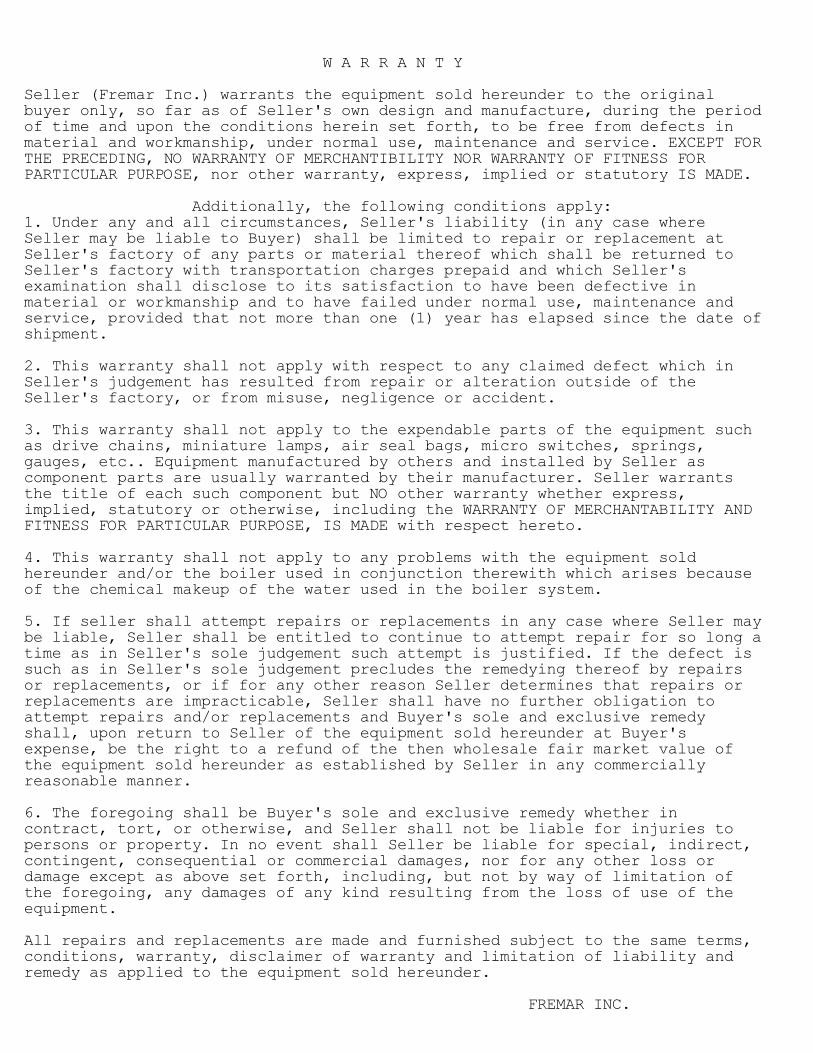
W A R R A N T Y Seller (Fremar Inc.) warrants the equipment sold hereunder to the original buyer only, so far as of Seller's own design and manufacture, during the period of time and upon the conditions herein set forth, to be free from defects in material and workmanship, under normal use, maintenance and service. EXCEPT FOR THE PRECEDING, NO WARRANTY OF MERCHANTIBILITY NOR WARRANTY OF FITNESS FOR PARTICULAR PURPOSE, nor other warranty, express, implied or statutory IS MADE. Additionally, the following conditions apply: 1. Under any and all circumstances, Seller's liability (in any case where Seller may be liable to Buyer) shall be limited to repair or replacement at Seller's factory of any parts or material thereof which shall be returned to Seller's factory with transportation charges prepaid and which Seller's examination shall disclose to its satisfaction to have been defective in material or workmanship and to have failed under normal use, maintenance and service, provided that not more than one (1) year has elapsed since the date of shipment. 2. This warranty shall not apply with respect to any claimed defect which in Seller's judgement has resulted from repair or alteration outside of the Seller's factory, or from misuse, negligence or accident. 3. This warranty shall not apply to the expendable parts of the equipment such as drive chains, miniature lamps, air seal bags, micro switches, springs, gauges, etc.. Equipment manufactured by others and installed by Seller as component parts are usually warranted by their manufacturer. Seller warrants the title of each such component but NO other warranty whether express, implied, statutory or otherwise, including the WARRANTY OF MERCHANTABILITY AND FITNESS FOR PARTICULAR PURPOSE, IS MADE with respect hereto. 4. This warranty shall not apply to any problems with the equipment sold hereunder and/or the boiler used in conjunction therewith which arises because of the chemical makeup of the water used in the boiler system. 5. If seller shall attempt repairs or replacements in any case where Seller may be liable, Seller shall be entitled to continue to attempt repair for so long a time as in Seller's sole judgement such attempt is justified. If the defect is such as in Seller's sole judgement precludes the remedying thereof by repairs or replacements, or if for any other reason Seller determines that repairs or replacements are impracticable, Seller shall have no further obligation to attempt repairs and/or replacements and Buyer's sole and exclusive remedy shall, upon return to Seller of the equipment sold hereunder at Buyer's expense, be the right to a refund of the then wholesale fair market value of the equipment sold hereunder as established by Seller in any commercially reasonable manner. 6. The foregoing shall be Buyer's sole and exclusive remedy whether in contract, tort, or otherwise, and Seller shall not be liable for injuries to persons or property. In no event shall Seller be liable for special, indirect, contingent, consequential or commercial damages, nor for any other loss or damage except as above set forth, including, but not by way of limitation of the foregoing, any damages of any kind resulting from the loss of use of the equipment. All repairs and replacements are made and furnished subject to the same terms, conditions, warranty, disclaimer of warranty and limitation of liability and remedy as applied to the equipment sold hereunder. FREMAR INC.

I N D E X Topic: Page: ─────────────────────────────────────────────────────────────── General Information .................................... 3 - 6 Unpacking & Locating the Steam Tunnel ................. 7 GARMENT PREPARATION AND HANDLING ....................... 8 - 10 Utility Connection ..................................... 11 PREOPERATIONAL CHECKLIST ............................... 12 - 13 OPERATING PROCEDURES ................................... 14 - 16 SAFETY SWITCHES ........................................ 17 - 18 PREVENTATIVE MAINTENANCE ............................... 19 - 24 Identifying Photographs ................................ 25 - 40 TROUBLESHOOTING AND REPAIRS ............................ 41 - 46 Repair Procedures ...................................... 47 - 51 Replacement Parts Index ................................ 52 - 56 Dimensional Drawings ................................... 57 - 58 Electrical Schematics .................................. end of manual 2

GENERAL INFORMATION (PART 1) A B O U T T H I S M A N U A L This technical manual was written with the understanding that, for the most part, its readers will come from two distinctly separate job classifications: machine operators, and maintenance/repair personnel. Though a comprehensive understanding of the entire contents would benefit both groups, our experience has shown that most readers will concentrate on those sections that they feel are relevant to their specific job responsibilities. In order to make your search for information much easier, the following graphic identifiers have been used: ▄▄▄▄▄▄▄▄▄▄▄▄▄▄▄▄▄▄▄▄▄▄▄▄▄▄▄▄▄▄▄▄▄▄▄▄▄▄▄▄▄▄▄▄▄▄▄▄▄▄▄▄▄▄▄ ▌ ▐ ▌ In order to emphasize information dealing with ▐ ▌ MAINTENANCE PROCEDURES, it will be separated from ▐ ▌ surrounding text by solid-line borders. ▐ ▌ ▐ ▀▀▀▀▀▀▀▀▀▀▀▀▀▀▀▀▀▀▀▀▀▀▀▀▀▀▀▀▀▀▀▀▀▀▀▀▀▀▀▀▀▀▀▀▀▀▀▀▀▀▀▀▀▀▀ ╔═════════════════════════════════════════════════════╗ ║ FACILITATING NOTES ARE ENCLOSED IN DOUBLE-LINE ║ ║ BORDERS. THEY SERVE TWO FUNCTIONS: ║ ║ ║ ║ 1. TO SERVE AS ROADSIGNS, IDENTIFYING THE NATURE ║ ║ OF THE TOPIC AT HAND AND DIRECTING YOU TO ║ ║ RELATED INFORMATION FOUND ELSEWHERE IN THIS ║ ║ MANUAL. ║ ║ ║ ║ 2. TO PASS ALONG ANY INSIGHTS THAT MAY MAKE THE ║ ║ JOB AT HAND EASIER OR LESS LIKELY TO RESULT ║ ║ IN INJURY TO PERSONNEL. ║ ╚═════════════════════════════════════════════════════╝ Appearing at the top of each page is a header that points to the topic(s) covered in the text of that page. When the topic spans more that one page, its continuation is marked by part numbers (PART 1, PART 2, etc.). 3

GENERAL INFORMATION (PART 2) H O W T O G E T T H E M O S T O U T O F Y O U R G A R M E N T S T E A M E R Your Steamer has been manufactured and tested under strict quality control standards. Under normal use and within the boundaries of recommended maintenance procedures, it should provide you with many years of reliable service. There are TWO PRIMARY FACTORS that will greatly influence your ability to operate your Steam Tunnel at peak efficiency. Both of these factors are within the control of the personnel that will be operating and maintaining the machine. They are: 1. The GARMENT HANDLING AND PREPARATION PROCEDURES that determine the condition of the garments when they reach the Steam Tunnel Finisher. Extensive consideration is given to this topic, beginning on page 8 of this manual. 2. The RECOMMENDED MAINTENANCE PROCEDURES that are detailed throughout this manual.
The Lexington Finisher is a fully automated, garment finisher that processes garment by its unique steam – heat – vibration cycle, minimizing the need for any finishing and pressing. The Lexington Finisher can effectively be used on most of the new fabrics manufactured under “Easy-Care” or “Durable Press” labels and garments that are steamed or pressed in finishing.
Our experience in commercial laundry and dry cleaning environments has illustrated that these two points cannot be over stressed. Most of the user complaints that we have encountered were remedied through increased attention to one or both of these controlling factors. 4

GENERAL INFORMATION (PART 3) F U N C T I O N A L D E S C R I P T I O N : (Sussman model Lexington) Your Steamer is capable of finishing from 850 to 3600 garments per hour; depending upon machine model, fabric type, and moisture content. Your machine has been equipped with a number of important safety features WHICH ARE NOT TO BE OVERRIDDEN OR DEFEATED IN ANY WAY. These safety mechanisms allow your Steam Tunnel to indicate that a problem exists. Normal operation will be terminated and cannot be resumed until corrective action is taken. Detailed information concerning interruptions in operation caused by safety systems begins on page 17. As implied by the generic term "steam tunnel", tunnel finishers possess internal cavities through which hangered garments pass by means of automated conveyors. This "tunnel" is functionally divided into parts: the steam chamber and the finishing chamber. As hangered garments enter the Steam Tunnel steam chamber (at the machine's "entrance end") the hangers trip a microswitch which sends power to the steam solenoid, resulting in the application of live steam to the garments' surfaces as they pass the steam nozzles. As a result, the textile fibers are conditioned and lubricated by the steam. After the last garment has passed through the steam chamber, the solenoid valve is shut off to conserve steam. The garments then pass through the air seal bags and into the finishing chamber where they are contacted by high-velocity
heated air. The chamber is heated by steam and thermostatically controlled electric heaters (except on all steam heated tunnels). Air is circulated from top downward in a closed loop by blowers vibrating the garments. This process relaxes the fabric, allowing it to return to its original state.
Finally, the garments leave the "tunnel" through the exit rotating air seals (at the machine's "exit end") in a wrinkle-free condition.
OPTIONAL VENT
The steam chamber has a vent which is located on top of the cabinet. The vent is provided for the customers convenience. When conditions dictate, this vent can be exhausted through ducting. (An optional exhaust fan will be required.) No additional vent hood is needed.
5
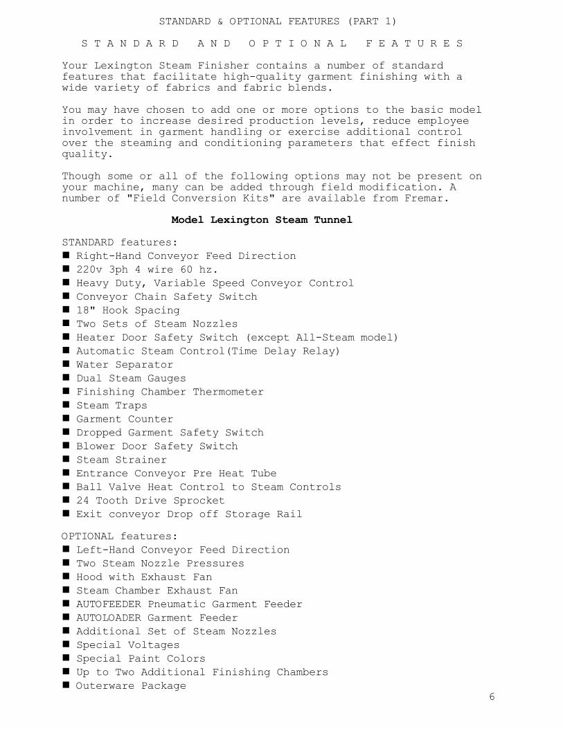
STANDARD & OPTIONAL FEATURES (PART 1) S T A N D A R D A N D O P T I O N A L F E A T U R E S Your Lexington Steam Finisher contains a number of standard features that facilitate high-quality garment finishing with a wide variety of fabrics and fabric blends. You may have chosen to add one or more options to the basic model in order to increase desired production levels, reduce employee involvement in garment handling or exercise additional control over the steaming and conditioning parameters that effect finish quality. Though some or all of the following options may not be present on your machine, many can be added through field modification. A number of "Field Conversion Kits" are available from Fremar. Model Lexington Steam Tunnel STANDARD features: Right-Hand Conveyor Feed Direction 220v 3ph 4 wire 60 hz. Heavy Duty, Variable Speed Conveyor Control Conveyor Chain Safety Switch 18" Hook Spacing Two Sets of Steam Nozzles Heater Door Safety Switch (except All-Steam model) Automatic Steam Control(Time Delay Relay) Water Separator Dual Steam Gauges Finishing Chamber Thermometer Steam Traps Garment Counter Dropped Garment Safety Switch Blower Door Safety Switch Steam Strainer Entrance Conveyor Pre Heat Tube Ball Valve Heat Control to Steam Controls 24 Tooth Drive Sprocket Exit conveyor Drop off Storage Rail OPTIONAL features: Left-Hand Conveyor Feed Direction Two Steam Nozzle Pressures Hood with Exhaust Fan Steam Chamber Exhaust Fan AUTOFEEDER Pneumatic Garment Feeder AUTOLOADER Garment Feeder Additional Set of Steam Nozzles Special Voltages Special Paint Colors Up to Two Additional Finishing Chambers Outerware Package 6

UNPACKING & LOCATING THE MACHINE U N P A C K I N G A N D L O C A T I N G Y O U R N E W V I B R A S T E A M E R UNPACKING: Before you begin to unpack your Steam Tunnel, pay special attention to any visible damage to the exterior of the shipping crate. Rough handling will usually leave evidence, alerting you to the possibility that damage was sustained in transit. If your machine has been damaged, notify the freight company immediately. It is your responsibility to file all damage claims with the carrier.
Your Steam Tunnel was pre-tested at our factory, carefully crated, and shipped in good working order. However, some fasteners may have loosened in transit. Check all fittings, set screws, bolts, etc. to insure tightness. A special steam nozzle clean-out tool is taped to the aluminum panel at the entrance end of the machine. Be sure to remove the tool and put it where it will be readily available. MACHINE LOCATION: DO NOT USE THE GARMENT CONVEYOR AS A HANDLE TO MOVE THE MACHINE. If a slick rail or screw conveyor is used to receive finished garments as they emerge from the Steam Tunnel, locate it approximately at right-angles (90°) to the adjustable garment knock-off assembly located on the conveyor at the machine's exit end [see photo, page 31]. 7

Fabric Yorktown Condord Saratoga Lexington Acrylic Acetate All knits including Nylon
2-3 psi Steam jets 1200/hr. Lowest drying temp.
2-3 psi Steam jets 1700-1800/hr. Lowest drying temp.
2-3 psi Steam jets 2200-2400/hr. Lowest drying temp.
2-3 psi Steam jets 3200-3600/hr. Lowest drying temp.
Nylon (woven) 3-4 psi Steam jets 850-950/hr. up to approx. 300°F drying temp.
3-4 psi Steam jets 1100-1200/hr. up to approx. 300°F drying temp.
3-4 psi Steam jets 1700-1900/hr. up to approx. 300°F drying temp.
3-4 psi Steam jets 2400-2600/hr. up to approx. 300°F drying temp.
100% Polyester Polyester-Cotton
7-12 psi Steam jets 850-950/hr. up to approx.290-300°F drying temp.
7-12 psi Steam jets 1100-1200/hr. up to approx.290-300°F drying temp.
7-12 psi Steam jets 1700-1900/hr. up to approx.290-300°F drying temp.
7-12 psi Steam jets 2400-2600/hr. up to approx.290-300°F drying temp.
100% Cotton Fleece Velours Corduroys Wool
15-20 psi Steam jets 850-950/hr. up to approx. 300°F drying temp.
15-20 psi Steam jets 1100-1200/hr. up to approx. 300°F drying temp.
15-20 psi Steam jets 1700-1900/hr. up to approx. 300°F drying temp.
15-20 psi Steam jets 2400-2600/hr. up to approx. 300°F drying temp.
NOTE: 1. Some 100% cottons will not process adequately through the system at any setting. NOTE: 2. When processing tops, knit or woven, a flatter side seam to side seam appearance to the garment will be obtained by framing the garment and processing through the Sussman LSK-600A Steam Tunnel. The act of framing will also eliminate side seam pucker and help flatten the hem. Productivity is in the order of 100 dozen garments per hour.

GARMENT PREPARATION & HANDLING (PART 1) G A R M E N T P R E P A R A T I O N A N D H A N D L I N G GENERAL OVERVIEW: As previously stated, the finish quality exhibited by garments exiting the Steam Tunnel varies directly with the attention given to conditioning procedures involved with the washing/drying or dry cleaning process. Specifically, inadequate temperature control during processing (resulting in a condition known as "thermal shock") has the greatest negative impact upon your Vibra Steamer's ability to deliver wrinkle-free garments. W A S H I N G R E C O M M E N D A T I O N S DETERGENTS & BLEACHES: When wet washing, load washers to only 60% of their rated capacities to promote proper washing and cool-down conditions. We do not recommend specific supplies since many full range, non- toxic detergents with various additives can be successfully used. However, we have found that one-shot blend, non-toxic detergent preparations are best as they provide more accurate control in the washroom. Our experience has shown that it is best to avoid the use of bleach except in heavily stained loads. When chlorine bleach is used in wash loads, precautions must be taken to neutralize chlorine carryover. These bleaches can leave a residue in garments, damaging many man-made fabrics and causing "permanent press" fabrics to lose their wrinkle-resistant characteristics. Inorganic or oxygen-type bleaches appear to be safe. HEAVILY SOILED COLORED GARMENTS: Load the washer to approximately 60% of its dry weight, all- cotton load capacity. Wet the load to suds level with a one-half hot and one-half cold water bath. Add the detergent as recommended by manufacturing company and bring the bath to 160° F. by steam injection. If a second suds bath is needed, its temperature should equal that of the first bath (160° F.). 8

GARMENT PREPARATION & HANDLING (PART 2) W A S H I N G R E C O M M E N D A T I O N S HEAVILY SOILED WHITE GARMENTS: Proceed as instructed for heavily soiled colored garments with the following exceptions: The recommended temperature for suds bath(s) is increased to 190° F. Bleach may be used in accordance with previous qualifications. If bleaching is performed at lower temperatures, observe cool- down procedures if the temperature drop between baths exceeds 15° F. RINSING (3 METHODS): 1. Thermal cool-down or flood-overflow rinse with cool-down occurring in the first rinse is accomplished by introducing hot water into the rinse bath at a temperature equal to or greater than that of the hottest bath. After one minute of basket agitation, initiate the cool-down cycle. Cool the load to approximate room temperature at a rate no faster that 15° F. per minute. Drain the rinse water and continue with subsequent cold water rinses. 2. Hot rinse with cool-down in the next-to-last rinse. Observe cool-down procedures as in first rinse of method #1. 3. Step-down cooling for washers not equipped with automatic thermal controls. Operator must visually monitor thermometer on the washer. Drain approximately 1/3 to 1/2 of the free water from the washer. Close the drain and refill with a mixture of hot and cold water sufficient to reduce the load temperature by 10° to 15° F.. Repeat this procedure to cool the load to approximate room temperature. The final rinse should contain full cold water. FINAL RINSE AND EXTRACTION: The final rinse should contain cold water only. Extract the garments as long as necessary to reduce retained moisture to an economical drying level (usually, about one-half the time required for cotton garments). PAY SPECIAL ATTENTION TO TEMPERATURE CONTROL DURING THESE CYCLES. Our experience has shown that wrinkles characterized as "extractor wrinkles" are often "thermal-shock creases" caused by improper cooling of the loads either during washing or before extraction. 9

GARMENT PREPARATION & HANDLING (PART 3) D R Y I N G P R O C E D U R E S (FOR BOTH WET WASHING AND DRYCLEANING) Load dryer to only 40% of its rated capacity in order to promote proper drying and cool-down conditions. Only use a dryer whose temperature can be accurately controlled at levels between 135° and 165° F., as this heat level is sufficient to dry poly-cotton garments. When the garments are dry, turn the dryer heat off and continue to tumble the load until its temperature reaches 100° F.. Remove the garments immediately after tumbling stops but be sure that the garments are thoroughly dried. Excessive moisture content in the garments will significantly reduce the Vibra Steamer's production speed. D R Y C L E A N I N G P R O C E D U R E S Many Steam Tunnel installations have reported a 25% reduction in garment finishing costs while achieving a 60% to 65% total pass- up on all drycleaned items. The remaining 35% to 40% required various degrees of touch-up work to pass inspection. On lady's wear alone, 75% pass-up rates have been achieved with 50% production increases and corresponding personnel reductions. Your Steam Tunnel's ability to reduce your finishing work varies directly with your adherence to the following recommendations. Run the garments through a complete machine cycle, using either a dry-to-dry or cold transfer unit. If a formula is used in which a quantity of water is added to the drycleaning compound, the garments should be dried until all solvent and water are removed. Damp garments will finish more slowly and their finish quality will be inferior to fully-dried garments. Relative to finish quality, THE MOST IMPORTANT STEP IN THE DRYCLEANING PROCESS INVOLVES CAREFUL TEMPERATURE CONTROL. Sufficient cool-down time must be allowed at the end of the drying cycle to reduce the garments' temperature to within 15° F. of room temperature. POST STEAM TUNNEL HANDLING SUGGESTIONS: 1. Process all dry cleaned garments through your Steam Tunnel that will tolerate heat and/or steam. 2. Place the inspection center near your Steam Tunnel's exit end. 3. Place a small puff iron and hand iron near the inspection area to touch-up the garments requiring additional hand work to pass inspection. 10

CONNECTING THE UTILITIES U T I L I T Y C O N N E C T I O N ╔═════════════════════════════════════════════════════════════╗ ║ DETAILED DIMENSIONAL DRAWINGS ARE PROVIDED ON PAGES 57 & 58 ║ ║ TO ASSIST YOU IN LOCATING THE CONNECTION POINTS FOR INCOMING║ ║ ELECTRICAL POWER, INCOMING STEAM, AND OUTGOING CONDENSATE ║ ║ RETURN. THE PHOTO ON PAGE 28 MAY ALSO BE HELPFUL. ║ ╚═════════════════════════════════════════════════════════════╝ INCOMING ELECTRICAL POWER: A circuit breaker or electrical disconnect box of sufficient rating is required to handle the electrical load requirements of your Steam Tunnel (see the serial number plate near the control box for exact electrical requirements). An external device must be provided because no such internal protection exists on the Steam Tunnel's incoming electrical power circuitry. In most cases, the nature and type of this external protection (i.e. circuit breaker or disconnect box) is dictated by the electrical codes prevailing in your area. Check with local authorities before connecting the electrical power. Note: Most electrical codes require a main disconnect switch to be mounted on or near the machine. INCOMING STEAM: BE SURE THAT THE STEAM SUPPLY LINE IS THOROUGHLY BLOWN OUT BEFORE CONNECTING TO THE MACHINE. To prevent damage to the steam tunnel steam traps, etc. A 1" diameter steam supply line must be run to your Steam Tunnel. Install a shut-off valve in this line so that the steam supply to the Steam Tunnel may be shut off for servicing or maintenance without effecting the operation of surrounding equipment. OUTGOING CONDENSATE RETURN: A 1/2" diameter condensate return line is required. Traps are provided on the Steam Tunnel, so no further trapping in this line is needed. OPTIONAL STEAM VENT: A circular, 5" diameter vent hole is provided on the top of the steam chamber. If necessary, an exhaust fan and ducting can be added to remove excess steam from the steam chamber. 11


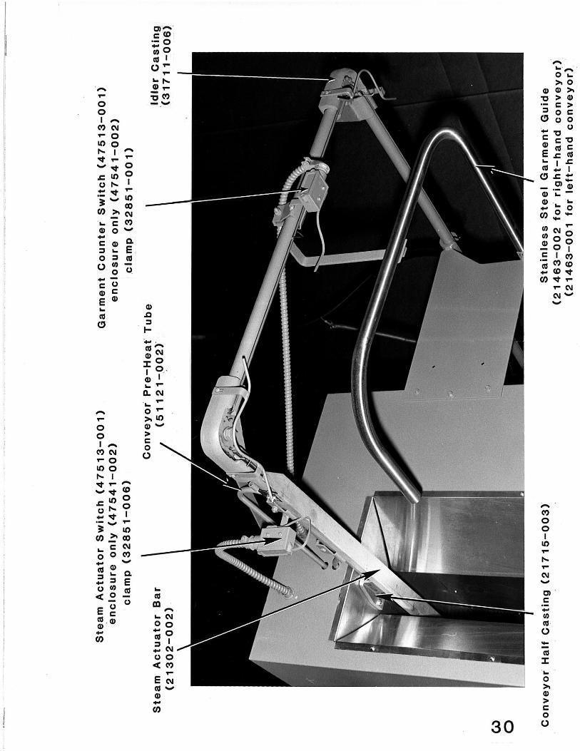
PREOPERATIONAL CHECKLIST (PART 1) P R E O P E R A T I O N A L C H E C K O U T A N D A D J U S T M E N T ╔════════════════════════════════════════════════════════════╗ ║ THESE PROCEDURES ARE INTENDED FOR ORIGINAL START-UP OF NEW ║ ║ STEAM TUNNEL INSTALLATIONS. ║ ╚════════════════════════════════════════════════════════════╝ Check the tightness of all working components, bolts, nuts, and screws on a daily basis for one week following original installation. Check electrical connections and tighten them if necessary. After all utilities have been connected, your Vibra Steamer is ready for its first start-up. Follow the procedures outlined below: 1. Furnish steam to the Steam Tunnel by opening the shut-off valve you installed in the incoming steam supply line. 2. Close the external circuit breaker or disconnect switch (determined by local electrical code), thereby providing electrical power to the machine. 3. Press the "START" push-button switch located on the machine's control panel. [see photo, page 26] 4. Visually verify that the finishing chamber's 3 phase blower motors are rotating in the direction indicated by the arrow shown on the motors. If the rotation direction is CORRECT, proceed to step 5. If the rotation direction is NOT CORRECT, do this: A. OPEN AND SAFETY TAG the external, electrical power supply disconnect switch and/or circuit breaker. B. Facing the Steam Tunnel's control panel, locate the high-voltage electrical access panel just above the control panel area. Remove this panel and reverse the positions of the left two wires of the incoming 3-phase power supply line where they attach to the machine's terminals. C. Replace the high-voltage electrical access panel and close the external power supply disconnect switch and/or circuit breaker that you opened in step A. E. Repeat steps 3 and 4 to visually verify that the blower motor is rotating in the direction indicated by the arrow. 5. Turn the conveyor speed control adjustment knob [see photo, page 26] to approximately 1/3 maximum speed. 12

PREOPERATIONAL CHECKLIST (PART 2) 6. Allow the Steam Tunnel to preheat for approximately 10 minutes but remain alert for unusual occurrences during this initial start-up procedure. 7. Press the STEAM push-button switch located on the control panel [see photo, page 26]. The rectangular steam "on" light below the push-button switch will light to signify that the machine is in steaming mode. 8. Locate the steam actuator switch on the conveyor at the entrance end of the machine [see photo, page 30]. Push the actuator until it actuates the steam, duplicating the sequence of events that occurs each time a hanger contacts the bar. Steam will be emitted from the steam nozzles inside the steam chamber. 9. Hanger a few test garments and hang them on conveyor hooks (be sure that the hanger's open neck travels forward -- toward the Steam Tunnel's entrance end). Observe the finish quality obtained and, if necessary, change the steam nozzle pressure(s) by adjusting the ball valve(s) located behind the plumbing access door next to the electrical control panel on the machine's right side [see photo, page 34]. 10. Check the thermometer on the exterior of the finishing chamber for desired operating temperature. 11. The adjustable garment knock-off assembly [see photo, page 31] can be located at virtually any desired point on the conveyor. This allows any involved screw conveyor or slick rail system (provided by others) to be located in the most convenient position. The trailing tangs of the knock-off are made of a malleable steel that allows adjustment. Additionally, the knock- off can be vertically adjusted (by means of four set screws) to facilitate its use with a wide variety of hanger types. This completes your Steam Tunnel's preoperational checklist. The machine is now ready for normal operation. 13

OPERATING PROCEDURES (PART 1) V I B R A S T E A M E R O P E R A T I O N A L C H E C K L I S T ╔═══════════════════════════════════════════════════════════════╗ ║ THESE PROCEDURES ARE INTENDED TO BE USED ANY TIME THE VIBRA ║ ║ STEAMER IS TO BE RESTARTED FOLLOWING A PERIOD OF TIME IN ║ ║ WHICH THE MACHINE WAS TURNED OFF, OR WHEN BEING RESTARTED ║ ║ FOLLOWING AN INTERRUPTION IN SERVICE OF SUFFICIENT DURATION ║ ║ THAT THE FINISHING CHAMBER THERMOMETER REGISTERS BELOW THE ║ ║ DESIRED OPERATING TEMPERATURE. ║ ╚═══════════════════════════════════════════════════════════════╝ S T A R T - U P : 1. Close the external electrical circuit breaker and/or disconnect switch, thereby providing incoming electrical power to the Steam Tunnel. 2. Open the steam shut-off valve in the incoming steam supply line to the machine, thereby providing incoming steam to the Steam Tunnel. 3. Press the START push-button on the control panel [see photo, page 26]. Allow the machine to warm up for approximately 10 minutes or until the finishing chamber thermometer reaches the desired operating temperature. 4. When the desired operating temperature is reached, press the STEAM push-button on the control panel [see photo, page 26]. The rectangular steam ready light below the push-button will illuminate. 14

O P E R A T I O N & S H U T - D O W N P R O C E D U R E S ╔═══════════════════════════════════════════════════╗ ║ THESE PROCEDURES ARE TO BE FOLLOWED WHENEVER THE ║ ║ STEAM TUNNEL IS USED. ║ ╚═══════════════════════════════════════════════════╝ O P E R A T I O N : 1. Before loading garments onto the conveyor, check the finishing chamber thermometer and the steam gauge to insure that settings are within the following limits: garment type air temp. range steam pressure ───────────────────────────────────────────────────────── delicate 235° to 265° F. approx. 15 lbs. others 335° to 365° F. approx. 25 lbs. Test run a few garments to insure that the steam, heat and speed settings will deliver the finish quality sought. (Of course, test garments must be representative of the general run in fabric type, moisture content, etc.). At first, we recommend keeping a log book to record the settings used for various garment and fabric types. 2. Load the hangered garments onto the conveyor hooks with the hanger's open neck travelling forward (toward the Steam Tunnel's entrance end). 3. Place permanent press pants on hangers just as they would appear when ready for delivery. We recommend that flocked-type hangers be used. 4. There is no standard success formula for obtaining the best possible garment finish. The Steam Tunnel gives you immediate and continuous control over the steam, heat, and speed parameters but each garment arrives with a set of its own variables (moisture content, fabric type, washroom treatment, etc.). Only experimentation will teach you how to achieve the best possible garment finish. 15

OPERATING PROCEDURES (PART 3) ╔═══════════════════════════════════════════════════╗ ║ THESE PROCEDURES ARE TO BE FOLLOWED WHENEVER THE ║ ║ STEAM TUNNEL IS USED. ║ ╚═══════════════════════════════════════════════════╝ S H U T D O W N : 1. Press the STOP push-button switch located on the control panel. 2. If production is to be suspended for some time, we recommend that the external electrical power circuit breaker and/or disconnect switch be opened to discontinue electrical power supply to the Steam Tunnel. 3. Close the shut-off valve in the incoming steam supply line to the Steam Tunnel. 16

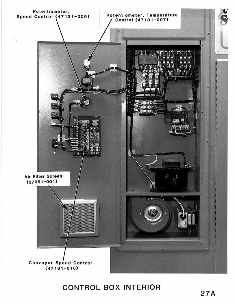
SAFETY SWITCHES (PART 1) S A F E T Y S W I T C H E S A number of electrical safety switches are provided as standard equipment on your Steam Tunnel. These switches were installed for the purpose of protecting both personnel and equipment from harm. Ultimately, the successful operation of these safety systems depends upon diligence with which they are maintained. ***************************************************************** T H E S A F E T Y S W I T C H E S A R E N O T T O B E O V E R R I D D E N O R D E F E A T E D I N A N Y W A Y . ***************************************************************** When machine operation is interrupted or prevented, it is usually due to the fact that one of the safety switches has detected an unacceptable operating condition. Normal Steam Tunnel operation may be resumed only when this abnormal condition has been remedied. HEATER DOOR SAFETY SWITCH: (NOT PRESENT ON ALL-STEAM MODEL). This switch is located on the left-hand interior wall of the finishing chamber, behind the electrical/steam heater access door [see photo, page 36]. Its function is to prevent accidental machine operation while servicing is being performed. BLOWER DOOR SAFETY SWITCH: located on the left-hand interior wall of the finishing chamber behind the blower access door [see photo, page 38], this switch prevents accidental machine operation while servicing is being performed. ▄▄▄▄▄▄▄▄▄▄▄▄▄▄▄▄▄▄▄▄▄▄▄▄▄▄▄▄▄▄▄▄▄▄▄▄▄▄▄▄▄▄▄▄▄▄▄▄▄▄▄▄▄▄▄▄▄▄▄▄▄ ▌ ▐ ▌ NOTE: THE ELECTRICAL ELEMENTS AND SURROUNDING METALLIC ▐ ▌ SURFACES BECOME EXTREMELY HOT DURING MACHINE OPERATION. ▐ ▌ WHEN SERVICING OF THIS AREA IS NECESSARY, BE CERTAIN ▐ ▌ THAT COMPONENTS ARE SUFFICIENTLY COOL TO PREVENT INJURY ▐ ▌ TO SERVICING PERSONNEL. ▐ ▌ ▐ ▀▀▀▀▀▀▀▀▀▀▀▀▀▀▀▀▀▀▀▀▀▀▀▀▀▀▀▀▀▀▀▀▀▀▀▀▀▀▀▀▀▀▀▀▀▀▀▀▀▀▀▀▀▀▀▀▀▀▀▀▀ PRESSURE DIFFERENTIAL SWITCH: (NOT PRESENT ON ALL-STEAM MODEL) This switch is located on the floor of the control box [see photo, page 27]. Its function is to insure that sufficient air flow exists within the finishing chamber to continue safe machine operation. Any significant reduction of the air flow over the electrical heater elements could cause them to fail. The pressure differential switch monitors air flow by means of a capillary tube which must be kept clear of obstructions at all times. 17

SAFETY SWITCHES (PART 2) S A F E T Y S W I T C H E S DROPPED GARMENT SAFETY SWITCH: Occasionally, a hangered garment will be knocked from a conveyor hook and fall to the floor of the Steam Tunnel. When this happens, a steel cable senses the event and trips the dropped garment microswitch; halting machine operation. When the garment has been removed, normal operation may resume. ▄▄▄▄▄▄▄▄▄▄▄▄▄▄▄▄▄▄▄▄▄▄▄▄▄▄▄▄▄▄▄▄▄▄▄▄▄▄▄▄▄▄▄▄▄▄▄▄▄▄▄▄ ▌ ▐ ▌ Operating and maintenance personnel must pay ▐ ▌ close attention to the condition and tension ▐ ▌ of the dropped garment cable. Tension must be ▐ ▌ sufficient to allow tripping of the safety ▐ ▌ switch by a single fallen garment. An external ▐ ▌ tension adjustment screw is provided at the ▐ ▌ Steam Tunnel's exit end. ▐ ▌ ▐ ▀▀▀▀▀▀▀▀▀▀▀▀▀▀▀▀▀▀▀▀▀▀▀▀▀▀▀▀▀▀▀▀▀▀▀▀▀▀▀▀▀▀▀▀▀▀▀▀▀▀▀▀ CONVEYOR CHAIN TENSION SAFETY SWITCH: The conveyor, chain and drive motor are protected by a mechanically activated, electrical safety switch located on the conveyor corner at the machine's exit end. In the event of chain obstruction caused by a jammed hook or hanger, this switch will halt normal machine operation until the obstruction is cleared. ▄▄▄▄▄▄▄▄▄▄▄▄▄▄▄▄▄▄▄▄▄▄▄▄▄▄▄▄▄▄▄▄▄▄▄▄▄▄▄▄▄▄▄▄▄▄▄▄▄▄▄▄ ▌ ▐ ▌ In some cases, the conveyor chain safety switch ▐ ▌ may prevent machine operation despite the ▐ ▌ absence of normal obstructions (jammed hooks, ▐ ▌ hangers, etc.). This occurrence is usually the ▐ ▌ result of one or both of these conditions: ▐ ▌ ▐ ▌ 1. The conveyor chain has become worn and has ▐ ▌ stretched beyond the adjustment limits of ▐ ▌ the safety mechanism. ▐ ▌ 2. The components of the safety mechanism are ▐ ▌ misaligned and must be adjusted. ▐ ▌ ▐ ▌ SEE PAGE 51 FOR FURTHER INSTRUCTIONS. ▐ ▌ ▐ ▀▀▀▀▀▀▀▀▀▀▀▀▀▀▀▀▀▀▀▀▀▀▀▀▀▀▀▀▀▀▀▀▀▀▀▀▀▀▀▀▀▀▀▀▀▀▀▀▀▀▀▀
The conveyor motor and 110vac control circuit is protected by a circuit breaker located on the main control panel.
The garment hangers are locked on the conveyor hooks by a safety guide bar, to prevent hanger drop off in the cabinet.
18

PREVENTATIVE MAINTENANCE (PART 1) P R E V E N T A T I V E M A I N T E N A N C E ╔══════════════════════════════════════════════════════════════╗ ║ THIS SECTION DESCRIBES NORMAL MAINTENANCE PROCEDURES. IF YOU ║ ║ ARE SEEKING INFORMATION CONCERNING A SPECIFIC MALFUNCTION, ║ ║ SEE THE "TROUBLE-SHOOTING AND REPAIR" SECTION BEGINNING ON ║ ║ PAGE 41. ║ ╚══════════════════════════════════════════════════════════════╝ ▄▄▄▄▄▄▄▄▄▄▄▄▄▄▄▄▄▄▄▄▄▄▄▄▄▄▄▄▄▄▄▄▄▄▄▄▄▄▄▄▄▄▄▄▄▄▄▄▄▄▄▄▄▄▄▄▄▄▄▄▄▄▄▄▄ ▌ ▐ ▌ WARNING: ▐ ▌ ▐ ▌ BEFORE BEGINNING ANY MAINTENANCE OR REPAIR PROCEDURE, ▐ ▌ TERMINATE ALL ELECTRICAL SUPPLY TO THE STEAM TUNNEL AND ▐ ▌ SAFETY TAG THE EXTERNAL CIRCUIT BREAKER AND/OR DISCONNECT ▐ ▌ SWITCH. ▐ ▌ ▐ ▌ CLOSE THE SHUT-OFF VALVE IN THE INCOMING STEAM SUPPLY LINE ▐ ▌ TO THE STEAM TUNNEL BEFORE WORKING ON OR NEAR ANY STEAM ▐ ▌ LINES OR COMPONENTS. IF THE MACHINE HAS RECENTLY BEEN IN ▐ ▌ USE, ALLOW SUFFICIENT TIME FOR HEATED COMPONENTS AND LINES ▐ ▌ TO COOL BEFORE PROCEEDING. ▐ ▌ ▐ ▌ FAILURE TO DO SO MAY RESULT IN SERIOUS INJURY TO PERSONNEL ▐ ▌ AND/OR DAMAGE TO THE EQUIPMENT. ▐ ▌ ▐ ▀▀▀▀▀▀▀▀▀▀▀▀▀▀▀▀▀▀▀▀▀▀▀▀▀▀▀▀▀▀▀▀▀▀▀▀▀▀▀▀▀▀▀▀▀▀▀▀▀▀▀▀▀▀▀▀▀▀▀▀▀▀▀▀▀ 19

PREVENTATIVE MAINTENANCE (PART 2) R E G U L A R L Y S C H E D U L E D P R E V E N T A T I V E M A I N T E N A N C E ╔═══════════════════════════════════════════════════════════════╗ ║ THE WORD "PREVENTATIVE" CANNOT BE OVEREMPHASIZED WITH REGARD ║ ║ TO THE MAINTENANCE PROCEDURES THAT FOLLOW. THERE IS NO ║ ║ SUBSTITUTE FOR A DILIGENT, CONSCIENTIOUSLY APPLIED ║ ║ PREVENTATIVE MAINTENANCE PROGRAM. ║ ╚═══════════════════════════════════════════════════════════════╝ D A I L Y P R O C E D U R E S : ▄▄▄▄▄▄▄▄▄▄▄▄▄▄▄▄▄▄▄▄▄▄▄▄▄▄▄▄▄▄▄▄▄▄▄▄▄▄▄▄▄▄▄▄▄▄▄▄▄▄▄▄▄▄▄▄▄▄▄▄▄▄▄▄▄ ▌ ▐ ▌ 1. A lint filter screen is located in the lower portion of ▐ ▌ the Steam Tunnel's finishing chamber [see photo, page ▐ ▌ ##]. This filter limits lint accumulation on the steam ▐ ▌ heaters and/or electrical elements that heat the ▐ ▌ chamber's high-velocity air. ▐ ▌ ▐ ▌ CLEAN THE LINT FILTER SCREEN DAILY until a normal rate ▐ ▌ of accumulation is determined. If lint build-up is light, ▐ ▌ cleaning may be performed every other day. If ▐ ▌ accumulation is heavy, clean twice daily. ▐ ▌ ▐ ▌ ▐ ▌ FIRES, RESULTING FROM EXCESSIVE LINT BUILD-UP, ARE NOT ▐ ▌ UNCOMMON WHEN THIS CLEANING PROCEDURE IS IGNORED! ▐ ▌ ▐ ▌ ▐ ▌ 2. CHECK THE ELECTRICAL HEATER ELEMENTS AND/OR THE STEAM ▐ ▌ HEATERS DAILY [see photo, pages 36 & 37] FOR LINT ▐ ▌ ACCUMULATION. If lint is present, clean them at once. ▐ ▌ ▐ ▀▀▀▀▀▀▀▀▀▀▀▀▀▀▀▀▀▀▀▀▀▀▀▀▀▀▀▀▀▀▀▀▀▀▀▀▀▀▀▀▀▀▀▀▀▀▀▀▀▀▀▀▀▀▀▀▀▀▀▀▀▀▀▀▀ 20

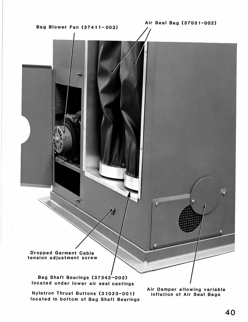
PREVENTATIVE MAINTENANCE (PART 3) W E E K L Y P R O C E D U R E S ▄▄▄▄▄▄▄▄▄▄▄▄▄▄▄▄▄▄▄▄▄▄▄▄▄▄▄▄▄▄▄▄▄▄▄▄▄▄▄▄▄▄▄▄▄▄▄▄▄▄▄▄▄▄▄▄▄▄▄▄▄▄▄▄▄ ▌ ▐ ▌ 1. Clean the control box cooling fan and filter [see photo, ▐ ▌ pages 27]. Check for lint accumulation around ▐ ▌ electrical components and clean if necessary. ▐ ▌ ▐ ▌ 2. Check the air seal bags [see photo, page 40] for signs of ▐ ▌ undue wear or damage. Remember that the air seal bags' ▐ ▌ function is to contain the high-velocity, heated air in ▐ ▌ the finishing chamber. The condition of the bags has a ▐ ▌ direct bearing on the finish quality and energy efficiency ▐ ▌ that your Steam Tunnel will deliver. ▐ ▌ ▐ ▌ 3. Check blower wheels for lint and clean if necessary. ▐ ▌ ▐ ▌ 4. Clean the Air Seal Bag Blower fan for lint build up - ▐ ▌ Clean if necessary. ▐ ▌ ▐ ▌ 5. Check Blower V Belt for wear or damage. ▐ ▌ ▐ ▌ ▐ ▀▀▀▀▀▀▀▀▀▀▀▀▀▀▀▀▀▀▀▀▀▀▀▀▀▀▀▀▀▀▀▀▀▀▀▀▀▀▀▀▀▀▀▀▀▀▀▀▀▀▀▀▀▀▀▀▀▀▀▀▀▀▀▀▀ 21
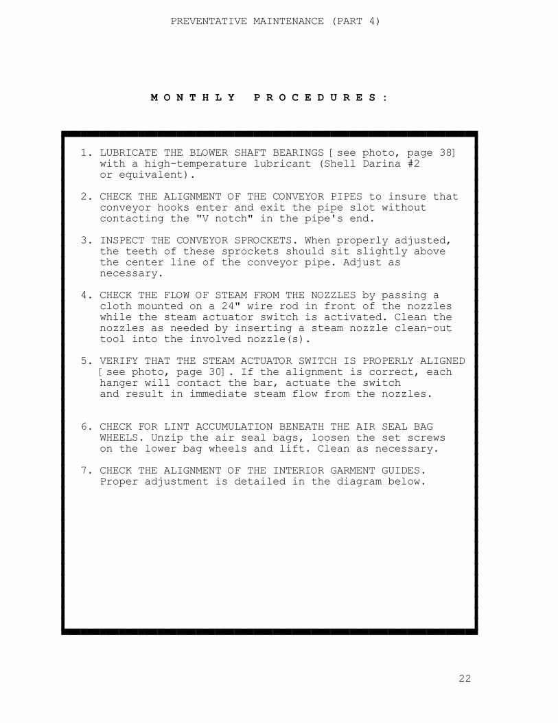
PREVENTATIVE MAINTENANCE (PART 4) M O N T H L Y P R O C E D U R E S : ▄▄▄▄▄▄▄▄▄▄▄▄▄▄▄▄▄▄▄▄▄▄▄▄▄▄▄▄▄▄▄▄▄▄▄▄▄▄▄▄▄▄▄▄▄▄▄▄▄▄▄▄▄▄▄▄▄▄▄▄▄▄▄▄▄ ▌ ▐ ▌ 1. LUBRICATE THE BLOWER SHAFT BEARINGS [see photo, page 38] ▐ ▌ with a high-temperature lubricant (Shell Darina #2 ▐ ▌ or equivalent). ▐ ▌ ▐ ▌ 2. CHECK THE ALIGNMENT OF THE CONVEYOR PIPES to insure that ▐ ▌ conveyor hooks enter and exit the pipe slot without ▐ ▌ contacting the "V notch" in the pipe's end. ▐ ▌ ▐ ▌ 3. INSPECT THE CONVEYOR SPROCKETS. When properly adjusted, ▐ ▌ the teeth of these sprockets should sit slightly above ▐ ▌ the center line of the conveyor pipe. Adjust as ▐ ▌ necessary. ▐ ▌ ▐ ▌ 4. CHECK THE FLOW OF STEAM FROM THE NOZZLES by passing a ▐ ▌ cloth mounted on a 24" wire rod in front of the nozzles ▐ ▌ while the steam actuator switch is activated. Clean the ▐ ▌ nozzles as needed by inserting a steam nozzle clean-out ▐ ▌ tool into the involved nozzle(s). ▐ ▌ ▐ ▌ 5. VERIFY THAT THE STEAM ACTUATOR SWITCH IS PROPERLY ALIGNED ▐ ▌ [see photo, page 30]. If the alignment is correct, each ▐ ▌ hanger will contact the bar, actuate the switch ▐ ▌ and result in immediate steam flow from the nozzles. ▐ ▌ ▐ ▌ ▐ ▌ 6. CHECK FOR LINT ACCUMULATION BENEATH THE AIR SEAL BAG ▐ ▌ WHEELS. Unzip the air seal bags, loosen the set screws ▐ ▌ on the lower bag wheels and lift. Clean as necessary. ▐ ▌ ▐ ▌ 7. CHECK THE ALIGNMENT OF THE INTERIOR GARMENT GUIDES. ▐ ▌ Proper adjustment is detailed in the diagram below. ▐ ▌ ▐ ▌ ▐ ▌ ▐ ▌ ▐ ▌ ▐ ▌ ▐ ▌ ▐ ▌ ▐ ▌ ▐ ▌ ▐ ▌ ▐ ▌ ▐ ▌ ▐ ▀▀▀▀▀▀▀▀▀▀▀▀▀▀▀▀▀▀▀▀▀▀▀▀▀▀▀▀▀▀▀▀▀▀▀▀▀▀▀▀▀▀▀▀▀▀▀▀▀▀▀▀▀▀▀▀▀▀▀▀▀▀▀▀▀ 22
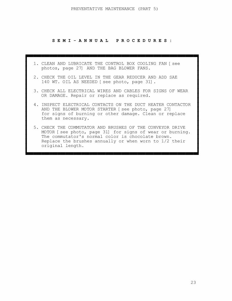
PREVENTATIVE MAINTENANCE (PART 5) S E M I - A N N U A L P R O C E D U R E S : ▄▄▄▄▄▄▄▄▄▄▄▄▄▄▄▄▄▄▄▄▄▄▄▄▄▄▄▄▄▄▄▄▄▄▄▄▄▄▄▄▄▄▄▄▄▄▄▄▄▄▄▄▄▄▄▄▄▄▄▄▄▄▄▄▄ ▌ ▐ ▌ 1. CLEAN AND LUBRICATE THE CONTROL BOX COOLING FAN [see ▐ ▌ photos, page 27] AND THE BAG BLOWER FANS. ▐ ▌ ▐ ▌ 2. CHECK THE OIL LEVEL IN THE GEAR REDUCER AND ADD SAE ▐ ▌ 140 WT. OIL AS NEEDED [see photo, page 31]. ▐ ▌ ▐ ▌ 3. CHECK ALL ELECTRICAL WIRES AND CABLES FOR SIGNS OF WEAR ▐ ▌ OR DAMAGE. Repair or replace as required. ▐ ▌ ▐ ▌ 4. INSPECT ELECTRICAL CONTACTS ON THE DUCT HEATER CONTACTOR ▐ ▌ AND THE BLOWER MOTOR STARTER [see photo, page 27] ▐ ▌ for signs of burning or other damage. Clean or replace ▐ ▌ them as necessary. ▐ ▌ ▐ ▌ 5. CHECK THE COMMUTATOR AND BRUSHES OF THE CONVEYOR DRIVE ▐ ▌ MOTOR [see photo, page 31] for signs of wear or burning. ▐ ▌ The commutator's normal color is chocolate brown. ▐ ▌ Replace the brushes annually or when worn to 1/2 their ▐ ▌ original length. ▐ ▌ ▐ ▀▀▀▀▀▀▀▀▀▀▀▀▀▀▀▀▀▀▀▀▀▀▀▀▀▀▀▀▀▀▀▀▀▀▀▀▀▀▀▀▀▀▀▀▀▀▀▀▀▀▀▀▀▀▀▀▀▀▀▀▀▀▀▀▀ 23

PREVENTATIVE MAINTENANCE (PART 6) C H A I N L U B R I C A T I O N ? ▄▄▄▄▄▄▄▄▄▄▄▄▄▄▄▄▄▄▄▄▄▄▄▄▄▄▄▄▄▄▄▄▄▄▄▄▄▄▄▄▄▄▄▄▄▄▄▄▄▄▄▄▄▄▄▄▄▄▄▄▄▄▄▄▄ ▌ ▐ ▌ WE DO NOT RECOMMEND LUBRICATION OF THE CONVEYOR CHAIN. ▐ ▌ Most lubricants tend to increase the accumulation of lint ▐ ▌ on chain components. Additionally, when the lubricant is ▐ ▌ heated (a natural consequence of Steam Tunnel operation), ▐ ▌ it may drip onto the garments. ▐ ▌ ▐ ▌ If chain lubrication is desired, use a dry, silicone-type ▐ ▌ lubricant. ▐ ▌ ▐ ▀▀▀▀▀▀▀▀▀▀▀▀▀▀▀▀▀▀▀▀▀▀▀▀▀▀▀▀▀▀▀▀▀▀▀▀▀▀▀▀▀▀▀▀▀▀▀▀▀▀▀▀▀▀▀▀▀▀▀▀▀▀▀▀▀ 24


TROUBLESHOOTING & REPAIR (PART 1) T R O U B L E S H O O T I N G A N D R E P A I R ╔═══════════════════════════════════════════════════════════════╗ ║ THE INFORMATION THAT FOLLOWS IS DESIGNED TO ASSIST YOU IN ║ ║ ISOLATING EQUIPMENT MALFUNCTIONS AND UNDERTAKING CORRECTIVE ║ ║ ACTION. FIRST, SCAN THE ITEMS APPEARING IN THE LEFT-HAND ║ ║ COLUMN, MARKED "SYMPTOM". WHEN YOU FIND A DESCRIPTION THAT ║ ║ MATCHES THE PROBLEM AT HAND, START AT THE TOP OF THE ║ ║ "PROBABLE CAUSE" COLUMN AND PERFORM THE "CORRECTIVE ACTION" ║ ║ RECOMMENDED. WORK YOUR WAY DOWNWARD THROUGH THE "PROBABLE ║ ║ CAUSE" - "CORRECTIVE ACTION" SETS UNTIL THE PROBLEM HAS BEEN ║ ║ SOLVED. ║ ║ ║ ║ ELECTRICAL CONTROL CIRCUIT AND HIGH-VOLTAGE SCHEMATICS ARE ║ ║ PROVIDED AT THE END OF THIS MANUAL. BE CERTAIN THAT THE ║ ║ SCHEMATIC YOU USE IS INTENDED FOR THE VOLTAGE OF YOUR ║ ║ MACHINE. ║ ╚═══════════════════════════════════════════════════════════════╝ ╔════════════════════╦══════════════════════╦════════════════════════════════╗ ║ SYMPTOM ║ PROBABLE CAUSE ║ CORRECTIVE ACTION ║ ╠════════════════════╬══════════════════════╬════════════════════════════════╣ ║ ║ ║ ║ ║ Steam stays on ║ Defective steam ║ Repair or replace. ║ ║ for incorrect ║ solenoid valve. ║ ║ ║ length of time. ║ [see photo,page 34] ║ ║ ║ ║ ║ ║ ╠════════════════════╬══════════════════════╬════════════════════════════════╣ ║ ║ ║ ║ ║ Steam nozzles ║ Steam actuator ║ Repair or replace. ║ ║ run continually. ║ switch defective. ║ ║ ║ ║ ║ ║ ║ ╟──────────────────────╫────────────────────────────────╢ ║ ║ ║ ║ ║ ║ Steam solenoid ║ Repair or replace. ║ ║ ║ valve sticking in ║ ║ ║ ║ open position. ║ ║ ║ ║ ║ ║ ║ ╟──────────────────────╫────────────────────────────────╢ ║ ║ ║ ║ ║ ║ Steam actuator bar ║ Adjust as required. ║ ║ ║ not returning to ║ ║ ║ ║ normal position. ║ ║ ║ ║ ║ ║ ╠════════════════════╬══════════════════════╬════════════════════════════════╣ 41

TROUBLESHOOTING & REPAIR (PART 2) ║ SYMPTOM ║ PROBABLE CAUSE ║ CORRECTIVE ACTION ║ ╠════════════════════╬══════════════════════╬════════════════════════════════╣ ║ ║ ║ ║ ║ No steam to ║ Ball valve(s) out ║ Readjust ball valve(s) [see ║ ║ Steam Tunnel's ║ of adjustment. ║ photo, page 34]. Be sure the ║ ║ steam nozzles. ║ ║ steam switch on control panel ║ ║ ║ ║ is "on", steam actuator ║ ║ ║ ║ switch is functioning and ║ ║ ║ ║ properly adjusted. ║ ║ ║ ║ ║ ║ ╟──────────────────────╫────────────────────────────────╢ ║ ║ ║ ║ ║ ║ Solenoid valve not ║ Replace coil. ║ ║ ║ opening due to ║ ║ ║ ║ defective coil. ║ ║ ║ ║ ║ ║ ║ ╟──────────────────────╫────────────────────────────────╢ ║ ║ ║ ║ ║ ║ Solenoid valve not ║ Replace diaphragm. ║ ║ ║ opening due to ║ ║ ║ ║ defective diaphragm.║ ║ ║ ║ ║ ║ ╠════════════════════╬══════════════════════╬════════════════════════════════╣ ║ ║ ║ ║ ║ Steam from ║ Steam traps not ║ Check the steam traps [see ║ ║ nozzles is wet, ║ operating correctly.║ photo, page 28]. Steam line ║ ║ spraying water ║ ║ temperature (LEAVING THE ║ ║ on garments. ║ ║ TRAP) should be 200°F. ║ ║ ║ ║ to 240°F.. If the steam line ║ ║ ║ ║ is cold, the line or trap is ║ ║ ║ ║ obstructed. If the lines to ║ ║ ║ ║ and from the trap are ║ ║ ║ ║ sizzling hot on both sides, ║ ║ ║ ║ the trap is malfunctioning ║ ║ ║ ║ by returning live steam ║ ║ ║ ║ directly back to the ║ ║ ║ ║ condensate return system. ║ ║ ║ ║ When this occurs, take the ║ ║ ║ ║ trap out and clean or ║ ║ ║ ║ replace it. ║ ║ ║ ║ ║ ╠════════════════════╬══════════════════════╬════════════════════════════════╣ ║ ║ ║ ║ ║ No steam is ║ Shut-off valve in ║ Open the shut-off valve. ║ ║ detected at the ║ incoming steam ║ ║ ║ Steam Tunnel but ║ supply line to the ║ ║ ║ the boiler steam ║ machine is closed. ║ ║ ║ pressure is ║ ║ ║ ║ normal. ║ ║ ║ ║ ║ ║ ║ ╠════════════════════╬══════════════════════╬════════════════════════════════╣ 42
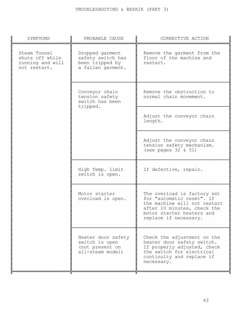
TROUBLESHOOTING & REPAIR (PART 3) ║ SYMPTOMS ║ PROBABLE CAUSE ║ CORRECTIVE ACTION ║ ╠════════════════════╬══════════════════════╬════════════════════════════════╣ ║ ║ ║ ║ ║ Steam Tunnel ║ Dropped garment ║ Remove the garment from the ║ ║ shuts off while ║ safety switch has ║ floor of the machine and ║ ║ running and will ║ been tripped by ║ restart. ║ ║ not restart. ║ a fallen garment. ║ ║ ║ ║ ║ ║ ║ ║ ║ ║ ║ ╟──────────────────────╫────────────────────────────────╢ ║ ║ ║ ║ ║ ║ Conveyor chain ║ Remove the obstruction to ║ ║ ║ tension safety ║ normal chain movement. ║ ║ ║ switch has been ║ ║ ║ ║ tripped. ╟────────────────────────────────╢ ║ ║ ║ ║ ║ ║ ║ Adjust the conveyor chain ║ ║ ║ ║ length. ║ ║ ║ ║ ║ ║ ║ ╟────────────────────────────────╢ ║ ║ ║ ║ ║ ║ ║ Adjust the conveyor chain ║ ║ ║ ║ tension safety mechanism. ║ ║ ║ ║ (see pages 32 & 51) ║ ║ ║ ║ ║ ║ ╟──────────────────────╫────────────────────────────────╢ ║ ║ ║ ║ ║ ║ High Temp. limit ║ If defective, repair. ║ ║ ║ switch is open. ║ ║ ║ ║ ║ ║ ║ ╟──────────────────────╫────────────────────────────────╢ ║ ║ ║ ║ ║ ║ Motor starter ║ The overload is factory set ║ ║ ║ overload is open. ║ for "automatic reset". If ║ ║ ║ ║ the machine will not restart ║ ║ ║ ║ after 10 minutes, check the ║ ║ ║ ║ motor starter heaters and ║ ║ ║ ║ replace if necessary. ║ ║ ║ ║ ║ ║ ╟──────────────────────╫────────────────────────────────╢ ║ ║ ║ ║ ║ ║ Heater door safety ║ Check the adjustment on the ║ ║ ║ switch is open ║ heater door safety switch. ║ ║ ║ (not present on ║ If properly adjusted, check ║ ║ ║ all-steam model) ║ the switch for electrical ║ ║ ║ ║ continuity and replace if ║ ║ ║ ║ necessary. ║ ║ ║ ║ ║ ╠════════════════════╬══════════════════════╬════════════════════════════════╣ 43

TROUBLESHOOTING & REPAIR (PART 4) ║ SYMPTOMS ║ PROBABLE CAUSE ║ CORRECTIVE ACTION ║ ╠════════════════════╬══════════════════════╬════════════════════════════════╣ ║ ║ ║ ║ ║ Air seal bag(s) ║ Bag blower fan ║ Check electrical circuitry ║ ║ not inflating. ║ not running. ║ to motor. ║ ║ ║ ║ ║ ║ ╟──────────────────────╫────────────────────────────────╢ ║ ║ ║ ║ ║ ║ Bag blower impeller ║ Clean the impeller. ║ ║ ║ clogged with lint. ║ ║ ║ ║ ║ ║ ║ ╟──────────────────────╫────────────────────────────────╢ ║ ║ ║ ║ ║ ║ Bag torn or ║ Mend, replace or zip the bag. ║ ║ ║ unzipped. ║ ║ ║ ║ ║ ║ ╠════════════════════╬══════════════════════╬════════════════════════════════╣ ║ ║ ║ ║ ║ Steam Tunnel ║ Interruption of ║ Check electrical power ║ ║ starts but ║ electrical power ║ supply to speed control. ║ ║ conveyor does not ║ to speed control. ║ ║ ║ operate when the ║ ║ ║ ║ START push-button ╟──────────────────────╫────────────────────────────────╢ ║ switch on the ║ ║ ║ ║ control panel ║ Conveyor motor or ║ Replace the motor or ║ ║ is pushed. ║ conveyor speed ║ speed control. ║ ║ ║ control are ║ ║ ║ ║ defective. ║ ║ ║ ║ ║ ║ ║ ╟──────────────────────╫────────────────────────────────╢ ║ ║ ║ ║ ║ ║ Gear reducer is ║ Repair or replace. ║ ║ ║ defective. ║ ║ ║ ║ ║ ║ ╠════════════════════╬══════════════════════╬════════════════════════════════╣ 44

TROUBLESHOOTING & REPAIR (PART 5) ║ SYMPTOMS ║ PROBABLE CAUSE ║ CORRECTIVE ACTION ║ ╠════════════════════╬══════════════════════╬════════════════════════════════╣ ║ ║ ║ ║ ║ Conveyor starts ║ Defective blower ║ Replace the defective coil. ║ ║ but blower ║ motor starter ║ ║ ║ motor does not ║ coil. ║ ║ ║ operate when ║ ║ ║ ║ START push-button ╟──────────────────────╫────────────────────────────────╢ ║ switch on control ║ ║ ║ ║ panel is pushed. ║ Blower motor ║ Replace the contactor. ║ ║ ║ starter contactor ║ ║ ║ ║ is defective. ║ ║ ║ ║ ║ ║ ║ ╟──────────────────────╫────────────────────────────────╢ ║ ║ ║ ║ ║ ║ Blower motor ║ Replace motor. ║ ║ ║ defective. ║ ║ ║ ║ ║ ║ ║ ╟──────────────────────╫────────────────────────────────╢ ║ ║ ║ ║ ║ ║ Blower wheels ║ Clean as required. ║ ║ ║ clogged with lint. ║ ║ ║ ║ ║ ║ ╠════════════════════╬══════════════════════╬════════════════════════════════╣ 45

TROUBLESHOOTING & REPAIR (PART 6) ║ SYMPTOMS ║ PROBABLE CAUSE ║ CORRECTIVE ACTION ║ ╠════════════════════╬══════════════════════╬════════════════════════════════╣ ║ ║ ║ ║ ║ Steam Tunnel ║ Steam heater is not ║ Clean or replace the ║ ║ operates but ║ operating due to ║ defective trap. ║ ║ finishing chamber ║ defective steam ║ ║ ║ thermometer will ║ trap. ║ ║ ║ not reach desired ║ ║ ║ ║ temperature. ╟──────────────────────╫────────────────────────────────╢ ║ ║ ║ ║ ║ ║ Defective duct ║ Replace the contactor. ║ ║ ║ heater contactor ║ ║ ║ ║ [see page 27]. ║ ║ ║ ║ (not present on ║ ║ ║ ║ all-steam model) ║ ║ ║ ║ ║ ║ ║ ╟──────────────────────╫────────────────────────────────╢ ║ ║ ║ ║ ║ ║ Defective pressure ║ Repair or replace the switch. ║ ║ ║ differential switch ║ ║ ║ ║ [see page 27] ║ ║ ║ ║ (not present on ║ ║ ║ ║ all-steam model) ║ ║ ║ ║ ║ ║ ║ ╟──────────────────────╫────────────────────────────────╢ ║ ║ ║ ║ ║ ║ Defective ║ Replace thermostat. ║ ║ ║ thermostat. ║ ║ ║ ║ [see page 27] ║ ║ ║ ║ ║ ║ ║ ╟──────────────────────╫────────────────────────────────╢ ║ ║ ║ ║ ║ ║ Defective heater ║ Replace the element. ║ ║ ║ element. ║ ║ ║ ║ [see page 36] ║ ║ ║ ║ (not present on ║ ║ ║ ║ all-steam model) ║ ║ ║ ║ ║ ║ ║ ╟──────────────────────╫────────────────────────────────╢ ║ ║ ║ ║ ║ ║ Incoming steam ║ Maintain 80 to 100 P.S.I. ║ ║ ║ pressure too low. ║ steam pressure. ║ ║ ║ ║ ║ ║ ╟──────────────────────╫────────────────────────────────╢ ║ ║ ║ ║ ║ ║ Defective ║ Replace thermometer. ║ ║ ║ thermometer. ║ ║ ║ ║ ║ ║ ╚════════════════════╩══════════════════════╩════════════════════════════════╝ 46

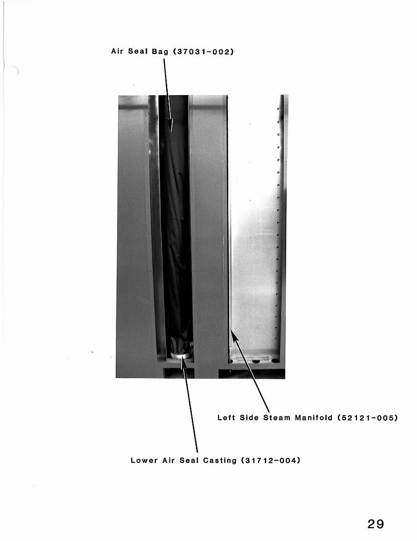
REPAIR PROCEDURES - AIR SEAL BAG REPLACEMENT (PART 1) ╔════════════════════════════════════════════════════════════════╗ ║ THIS SECTION CONTAINS DETAILED INSTRUCTIONS FOR PERFORMING THE ║ ║ REPAIRS AND/OR ADJUSTMENTS MOST COMMONLY ENCOUNTERED BY VIBRA ║ ║ STEAMER OWNERS. ║ ║ ║ ║ ******************************************************** ║ ║ BEFORE UNDERTAKING ANY REPAIR OR MAINTENANCE PROCEDURE, ║ ║ DISCONNECT AND SAFETY TAG THE INCOMING ELECTRICAL POWER ║ ║ SUPPLY TO THE STEAM TUNNEL. IF THE PROCEDURE INVOLVES ║ ║ CONTACT WITH STEAM LINES OR COMPONENTS: CLOSE THE SHUT- ║ ║ OFF VALVE IN THE STEAM SUPPLY LINE TO THE STEAM TUNNEL, ║ ║ BLEED ALL STEAM FROM THE LINES, AND ALLOW STEAM LINES AND ║ ║ COMPONENTS TO COOL BEFORE BEGINNING WORK. ║ ║ ******************************************************** ║ ║ ║ ║ BEFORE BEGINNING ANY OF THESE PROCEDURES, READ THROUGH THE ║ ║ INSTRUCTIONS AND BE CERTAIN THAT YOU HAVE OBTAINED ALL OF THE ║ ║ REPLACEMENT PARTS NECESSARY TO COMPLETE THE JOB. ║ ╚════════════════════════════════════════════════════════════════╝ A I R S E A L B A G R E M O V A L A N D R E P L A C E M E N T REMOVE THE INTERNAL AIR SEAL BAGS AS FOLLOWS: 1. Remove the access panel located on the left side of the machine [see photo, page 29]. 2. Remove the aluminum air seal bag cover to gain access to the bags. 3. Rotate the bag to expose its zipper and open the zipper to the upper casting. 4. Pull the bag loose from the lower air seal casting (the bag is held to the casting by a bag snap ring). Remove the bag snap ring from the bag's hem. 5. Loosen the upper air seal casting's set screws and slide it down the bag shaft about 5 or 6 inches. 6. Open the zipper completely and remove the bag retainer screw on the top of the upper casting. 7. Remove the bag. REPEAT STEPS 3 THRU 7 TO REMOVE THE OTHER INTERNAL AIR SEAL BAG, AND BOTH OF THE BAGS AT THE MACHINE'S EXIT END. 47

REPAIR PROCEDURES - AIR SEAL BAG REPLACEMENT (PART 2) REPLACE THE INTERNAL AIR SEAL BAGS AS FOLLOWS: Be sure to replace the innermost bag first. 1. Slip the bag over the upper casting and locate its zipper over the flat side of the casting. Close the zipper 3 to 4 inches. 2. Replace the bag retainer screw that you removed in step 6, above. 3. Insert the bag snap ring into the bag's lower hem. Press the bag and ring into the grove on the inside of the lower air seal casting until they snap into place. 4. Slide the upper air seal casting upward on the bag shaft until the bag is pulled taut. Slide the casting 1/2" downward on the shaft to provide a little slack and tighten the set screws on the upper casting to fix its position on the shaft. 5. Close the zipper fully. 6. Replace the aluminum air seal cover that you removed to gain access to the bags. 7. Replace the outer access panel. REPEAT STEPS 1 THRU 5 TO INSTALL NEW BAGS AT THE STEAM TUNNEL'S EXIT END. 48

REPAIR PROCEDURES - SOLENOID VALVE REPLACEMENT S T E A M S O L E N O I D V A L V E R E P L A C E M E N T ╔═══════════════════════════════════════════════════════════════╗ ║ THIS PROCEDURE INVOLVES CONTACT WITH STEAM LINES AND ║ ║ COMPONENTS. BEFORE ATTEMPTING REPAIR, CLOSE THE SHUT-OFF ║ ║ VALVE ON THE INCOMING STEAM SUPPLY LINE TO THE VIBRA ║ ║ STEAMER, BLEED THE STEAM LINE, AND ALLOW THE MACHINE TO COOL. ║ ╚═══════════════════════════════════════════════════════════════╝ TO REMOVE AND REPLACE THE STEAM SOLENOID VALVE: 1. Locate the solenoid behind the plumbing access door, near the control box on the right-hand side of the machine. [see photo, page 34]. 2. Disconnect electrical wires at the junction box. 3. Loosen the couplings in the steam line and remove the solenoid. 4. Install the new solenoid valve and secure the couplings in the steam line. 5. Reattach the wires that you removed in step 2 and insulate the connections. 6. Restore electrical power and steam to the Steam Tunnel and resume normal operation. THE STEAM SOLENOID VALVE CONTAINS TWO COMPONENT PARTS WHICH MAY BE INDEPENDENTLY REPLACED. THESE PARTS (THE COIL AND THE DIAPHRAGM) ARE AVAILABLE FOR PURCHASE FROM FREMAR.
A D J U S T M E N T T I M E D E L A Y R E L A Y
After the last garment has entered the Steam Tunnel, the time delay relay should hold the steam solenoid open for sufficient time to allow adequate steaming of garment. To adjust the Time Delay Relay, perform the following procedures:
1. Open control panel 2. Rotate adjustment knob to increase or decrease length of time that
steam is being emitted. 3. Actuate microswitch by hand three times, checking each cycle. 4. Close control panel and secure.
49

REPAIR PROCEDURES - CONVEYOR HOOKS C O N V E Y O R H O O K R E P L A C E M E N T [see photo, page 33] EACH CONVEYOR HOOK IS COMPRISED OF A MASTER LINK ASSEMBLY THAT PERMITS HOOK REPLACEMENT AS FOLLOWS: 1. Press the STOP push-button on the control panel when the defective hook is centered on a conveyor corner. 2. DISCONNECT AND SAFETY TAG THE INCOMING ELECTRICAL POWER SUPPLY to the Steam Tunnel. 3. Remove or loosen the tension spring on the conveyor chain tension safety assembly [see photo, page 32]. 4. Remove the retainer clip from the defective hook's master link. 5. Remove the master link with the defective hook attached. 6. Place the new master link in the chain and secure it with the retainer clip you removed in step 4. The retainer clip should be placed with its split end facing AWAY from the direction in which the chain travels. 7. Reconnect the tension spring on the conveyor chain tension safety assembly that you removed or loosened in step 3. 8. Restore electrical power to the Steam Tunnel and resume normal machine operation. 50

REPAIR PROCEDURES - CONVEYOR CHAIN TENSION SAFETY ASSY. C O N V E Y O R C H A I N T E N S I O N S A F E T Y A S S Y R E P A I R A N D A D J U S T M E N T ╔════════════════════════════════════════════════════════════════╗ ║ THE LENGTH OF THE CONVEYOR CHAIN WILL INCREASE AS ITS ║ ║ COMPONENT PARTS BECOME WORN. THE CONVEYOR CHAIN TENSION SAFETY ║ ║ MECHANISM MONITORS CHAIN TENSION AND ALLOWS MACHINE OPERATION ║ ║ WHEN THIS TENSION IS WITHIN ALLOWABLE LIMITS. SINCE THE SAFETY ║ ║ MECHANISM MAKES NO DISTINCTION BETWEEN CHAIN THAT IS TOO ║ ║ LOOSE AND CHAIN THAT IS TOO TIGHT, AN INTERRUPTION IN SERVICE ║ ║ WILL RESULT IF THE CHAIN BECOMES EXCESSIVELY LOOSE. ║ ║ ║ ║ THIS SITUATION MAY BE REMEDIED BY ONE OF THE FOLLOWING ║ ║ METHODS: ║ ║ ║ ║ 1. REMOVING CHAIN LINKS TO RETURN THE CHAIN TO ITS ║ ║ ORIGINAL LENGTH. ║ ║ ║ ║ 2. INSTALLING A NEW CHAIN. ║ ║ ║ ║ 3. ADJUSTING THE CHAIN TENSION SAFETY MECHANISM. ║ ╚════════════════════════════════════════════════════════════════╝ THE FOLLOWING INSTRUCTIONS ARE INVOLVED WITH ADJUSTMENTS TO THE CHAIN TENSION SAFETY MECHANISM: [see photos, page 32] 1. THE SAFETY MICROSWITCH is activated by either of two nuts that are spaced 1/2" apart on a threaded rod. THE SPACING BETWEEN THESE NUTS NEED NOT BE ALTERED, but their relative positions on the rod may be adjusted. Under normal operating conditions with a fully loaded conveyor, the microswitch's roller-sensor should be located at the midpoint between these two nuts. 2. CHAIN TENSION is maintained by a spring-loaded, sliding sprocket assembly. When the chain stretches, the tension spring recoils and trips the safety microswitch, halting machine operation (the spring EXTENDS when normal chain tension is altered by an obstruction, but the effect is the same: the microswitch trips and the machine shuts down). NOTE: As adjustments are made to this assembly, one consideration remains most important. NO ADJUSTMENTS MAY BE MADE WHICH WILL COMPROMISE THE FUNCTIONALITY OF THE SAFETY ASSEMBLY. This consideration is most important when adjustments threaten to limit the "inward" and "outward" play in the sliding sprocket assembly. UNDER NO CIRCUMSTANCES, ARE ADJUSTMENTS ALLOWED WHICH WILL RESULT IN LESS THAT 1/4" INWARD AND OUTWARD PLAY IN THE SLIDING SPROCKET. Following any adjustments to this assembly, test the functioning of the mechanism before resuming normal machine operation. Testing may be accomplished by manually holding back on a hook while the conveyor is operating. This pressure should be sufficient to trip the microswitch; halting conveyor operation. 51

REPLACEMENT PARTS INDEX (PART 1) Sussman model Lexington
R E P L A C E M E N T P A R T S I N D E X ╔═══════════════════════════════════════════════════════════════╗ ║ WHEN ORDERING REPLACEMENT PARTS, PAY CAREFUL ATTENTION TO THE ║ ║ PART NUMBER LISTED IN THIS INDEX AND BE CERTAIN THAT IT IS ║ ║ ACCURATELY RELAYED TO THE FREMAR EMPLOYEE WHO WILL PROCESS ║ ║ YOUR ORDER. IT IS ADVISABLE THAT YOU ALSO PROVIDE ALL THE ║ ║ INFORMATION THAT APPEARS ON THE SERIAL NUMBER PLATE OF YOUR ║ ║ MACHINE (LOCATED ON THE CONTROL BOX). THIS INFORMATION CAN ║ ║ SUPPLY VALUABLE CROSS-REFERENCING ASSISTANCE THAT WILL MAKE ║ ║ IT MUCH EASIER FOR US TO PROMPTLY AND EFFICIENTLY SUPPLY THE ║ ║ PARTS YOU NEED. ║ ╚═══════════════════════════════════════════════════════════════╝ ELECTRICAL COMPONENTS (located in CONTROL BOX - see photos, pages 26 & 27) PART # DESCRIPTION 47212-006 7 Amp Circuit Breaker 47512-009 Push-button "Start" Switch 47512-010 Push-button "Stop" Switch 47512-011 Push-button "Steam" Switch 47011-007 Steam "On" Light 47121-003 Garment Counter 47161-016 Conveyor Speed Control 47131-009 Potentiometer for Speed Control 37411-003 Control Box Cooling Fan 47171-004 Temperature Control Circuit Board 47522-003 Pressure Differential Switch 47111-005 Duct Heater Contactor 47033-003 Complete Blower Motor Starter 47182-001 Transformer (1 KVA 208v/50-60hz/3ph) 47182-002 Transformer (1 KVA 230-460v/50-60hz/3ph) 47131-007 Potentiometer for Temperature Control 47142-010 Time Delay Relay 1-60sec 120v O108-A8 47322-011 Socket, 11 pin Octal type (for TDR) ELECTRICAL COMPONENTS (located on CONVEYOR) PART # DESCRIPTION 47513-001 Steam & Counter Microswitch [see photo, page 30] 47541-002 Microswitch Enclosure (for switch above) 47494-005 Conveyor Drive Motor [see photo, page 31] 47521-001 Conveyor Chain Safety Microswitch [see photo, page 32] 52
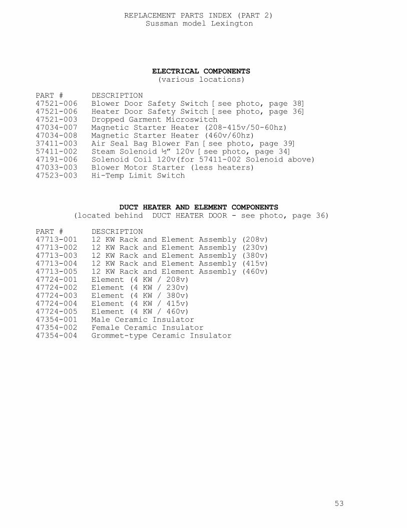
REPLACEMENT PARTS INDEX (PART 2) Sussman model Lexington
ELECTRICAL COMPONENTS (various locations) PART # DESCRIPTION 47521-006 Blower Door Safety Switch [see photo, page 38] 47521-006 Heater Door Safety Switch [see photo, page 36] 47521-003 Dropped Garment Microswitch 47034-007 Magnetic Starter Heater (208-415v/50-60hz) 47034-008 Magnetic Starter Heater (460v/60hz) 37411-003 Air Seal Bag Blower Fan [see photo, page 39] 57411-002 Steam Solenoid ½” 120v [see photo, page 34] 47191-006 Solenoid Coil 120v(for 57411-002 Solenoid above) 47033-003 Blower Motor Starter (less heaters) 47523-003 Hi-Temp Limit Switch DUCT HEATER AND ELEMENT COMPONENTS (located behind DUCT HEATER DOOR - see photo, page 36) PART # DESCRIPTION 47713-001 12 KW Rack and Element Assembly (208v) 47713-002 12 KW Rack and Element Assembly (230v) 47713-003 12 KW Rack and Element Assembly (380v) 47713-004 12 KW Rack and Element Assembly (415v) 47713-005 12 KW Rack and Element Assembly (460v) 47724-001 Element (4 KW / 208v) 47724-002 Element (4 KW / 230v) 47724-003 Element (4 KW / 380v) 47724-004 Element (4 KW / 415v) 47724-005 Element (4 KW / 460v) 47354-001 Male Ceramic Insulator 47354-002 Female Ceramic Insulator 47354-004 Grommet-type Ceramic Insulator 53

REPLACEMENT PARTS INDEX (PART 3) Sussman model Lexington
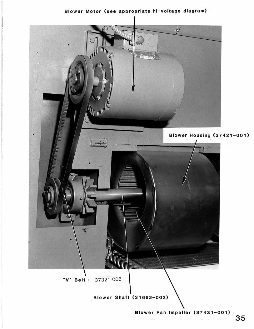
CONVEYOR COMPONENTS PART # DESCRIPTION 37121-015 24-Tooth Drive Sprocket 37121-003 12-Tooth Corner Sprocket 37010-003 Shoulder Bolt (for 12-tooth sprocket above) 32353-005 6-Tooth Idler Sprocket 37010-002 Shoulder Bolt (for 6-tooth sprocket above) 31711-004 Safety Corner Casting[see photo, page 32] 31711-001 Idler Corner Casting [see photo, page 30] 31711-008 Drive Corner Casting for 24 tooth sprocket 31715-001 Conveyor Support Casting (Full) 31715-003 Conveyor Support Casting (Half) [see photo, page 30] 37041-005 Safety Corner Tension Spring [see photo, page 32] 33337-001 Adjustable Garment Knock-Off Assy. [see photo, page 31] 37111-006 Gear Reducer [see photo, page 31] 32623-001 Corner Hanger Guide 21358-001 Corner Hanger Guide Aluminum style 32323-017 54-7/16” Entrance End Chromeline Conveyor Pipe w/Guide
32324-017 54-7/16" Entrance End Chromeline w/adjustible Guide 31324-017 54-7/16" Entrance End Chromeline w/collars
32323-014 41-3/4” Blower Chamber Chromed Conveyor Pipe w/Guide 32324-014 41-3/4" Blower Chamber Chromeline w/adjustable Guide 31324-014 41-3/4" Blower Chamber Chromeline w/collars 32825-012 Right-Hand Conveyor Entrance End Slotted Pipe w/Brkt(27-1/4”)
31321-011 Right-Hand Conveyor Exit End Slotted Pipe (24 5/8") 32825-015 11-3/8" Left-Hand Conveyor Entrance End Slotted Pipe w/Brkt 31321-056 15” Left-Hand Conveyor Exit End Slotted Pipe 32323-020 16 3/4" Exit End Slotted Conveyor Pipe 51121-002 Conveyor Pre-Heat Tube [see photo, page 30] 21463-001 Left-Hand Conveyor Stainless Steel Garment Guide [see photo, page 30] 21463-002 Right-Hand Conveyor Stainless Steel Garment Guide [see photo, page 30] 33337-002 Hanger Release, L.H. for Pos. Keeper Hooks 33337-003 Hanger Release, R.H. for pos. Keeper Hooks 33336-005 Loader, Hook Manual R.H. for Pos. Keeper Hooks 33336-006 Loader, Hook Manual L.H. for Pos. Keeper Hooks 33336-007 Loader, Hook R.H. Autoloader & Pos. Keeper Hooks 33336-008 Loader, Hook L.H. Autoloader & Pos. Keeper Hooks 54

REPLACEMENT PARTS INDEX (PART 4) Sussman model Lexington
CONVEYOR CHAIN COMPONENTS PART # DESCRIPTION 32311-058 Complete Left-Hand Conveyor Chain with 18" Hook Spacing
15 hooks(23' 8" length) 32311-053 Complete Right-Hand Conveyor Chain with 18" Hook Spacing
18 hooks(26' 4" length) 32311-139 Complete Left-Hand Conveyor Chain with 22” Hook Spacing 13 hooks(23' 8" length) 32311-138 Complete Right-Hand Conveyor Chain with 22” Hook Spacing 14 hooks (26' 4" length) 37714-001 Master Link Assembly (coupler) 37712-002 Master Link Assembly (offset) 32633-001 #41 Chain Hook Assembly (note: Replaced by 32312-002) 32312-002 Hook, Flat "J" Heavy Duty Assembly 32312-002 Hook, RH Positive Keeper T/F A315-E17 32633-010 Hook, LH positive Keeper T/F A315-E18 32633-012 Hook, RH Positive Keeper for plastic hangers 32633-013 Hook, LH Positive Keeper for plastic hanger 32633-015 Hook, LH Positive Keeper w/Extended Latch 32633-014 Hook, RH Positive Keeper w/Extended Latch BLOWER COMPONENTS PART # DESCRIPTION 47405-003 Blower Motor 5 hp.(208-230/460v/50-60hz) [see photo, page 35] 37421-001 Blower Housing [see photo, page 35] 37431-001 Blower Fan Impeller [see photo, page 35] 31662-003 Blower Shaft [see photo, page 35] 37341-003 Blower Shaft Bearing [see photo, page 38] 31716-002 Heat Sink Casting [see photo, page 38] 37321-003 "V" Belt [see photo, page 35] 37311-004 Sheave 37331-002 Bushing, Motor Sheave 37331-006 Bushing, Blower Sheave STEAM SYSTEM COMPONENTS PART # DESCRIPTION 57412-001 Ball Valve [see photo, page 34] 57421-001 3/4" Water Separator (optional equipment) 57463-001 60lb. Steam (manifold) Pressure Gauge 57462-003 160lb. (incoming) Steam Pressure Gauge 57416-001 Pressure Regulating Valve 57473-001 Repair Kit (for valve above) 57411-002 1/2" Steam Solenoid Valve [see photo, page 34] 57471-011 Diaphragm Repair Kit (for solenoid valve above) 47191-006 Solenoid Coil (for 57411-002 valve) 57451-003 Steam Heater [see photo, page 37] 57401-001 Steam Nozzle 57011-001 Clean-out Tool (for nozzle above) 52122-009 Lower Steam Manifold (22") 52121-005 Side Steam Manifold (60") 57441-003 1/2" Steam Trap [see photo, page 28] 57431-002 3/4" Steam Strainer [see photo, page 34] 57413-002 1/2" Check Valve 55

REPLACEMENT PARTS INDEX (PART 5) Sussman model Lexington
AIR SEAL COMPONENTS PART # DESCRIPTION
37031-001 Air Seal Bag 65-1/2” (Std. until 1980) 37031-002 Air Seal Bag 68-1/4” (Tall, Std. after 1980)[see photo, page 40]
37031-010 Air Seal Bag 67” (machine with Positive Keeper Hooks after 1980) 31712-004 Lower Casting [see photo, page 29] 31712-001 Upper Casting 31661-003 Bag Shaft 37342-002 Bag Shaft Bearing [see photo, page 33] 37151-002 Bag Snap Rings 31023-001 Nylatron Thrust Button 31868-001 Bearing Mounting Plate 32723-004 36-Tooth Bag Shaft Sprocket MISCELLANEOUS COMPONENTS PART # DESCRIPTION 37061-001 Thermometer (6" stem) 37061-002 Thermometer (15" stem) Super-D only 37444-005 90° 1/2" Grease Fitting (1/4-28 thread) 32335-016 Dropped Garment Cable Assembly 22142-002 Lint Filter Cover Assembly 22661-007 Lint Filter (screen only)

Set Screw
Bearing 1”37342-002
36 Tooth Sprocket32723-004
Conveyor Support Casting31715-001
Set Screw
Bag Shaft 1” x 76-1/2”31661-003
Nylon Thrust Button31023-001
Set Screw
Bearing 1”37342-002
Set Screw
Lower Air Seal Fixture31712-004
Set Screw
Air Seal Bags
Upper Air Seal Fixture31712-001
Center line
Typical front view of Air Seal Bags assembly
Snap Ring37151-002Slid into hem of air seal bagand snaped into lower fixture.
10-32 x 1/2”Truss HdSlotted screwand 10-32 nut(to lock airseal bag toupper fixture)

SUSSMAN-AUTOMATIC CORP.43-20 34TH STLONG ISLAND CITY, NY 11101
IDENTIFICATION SHEET FORSTEAM FINISHING TUNNELPOSITIVE KEEPER HOOKS
Please see page 2 for Hooks with Extended Latch
PAGE 1

21460-018 21460-019
Extended LatchRight Hand
Extended LatchLeft Hand
Extended latches when used with above hooks make part numbers:32633-014 HOOK, RH POSITIVE KEEPER WITH EXTENDED LATCH
32633-015 HOOK, LH POSITIVE KEEPER WITH EXTENDED LATCH
Extended latches can be put under item 4 or on top of item 4 (see above hooks) Please specify preferance.(normally put under latch(item 4)
PAGE 2
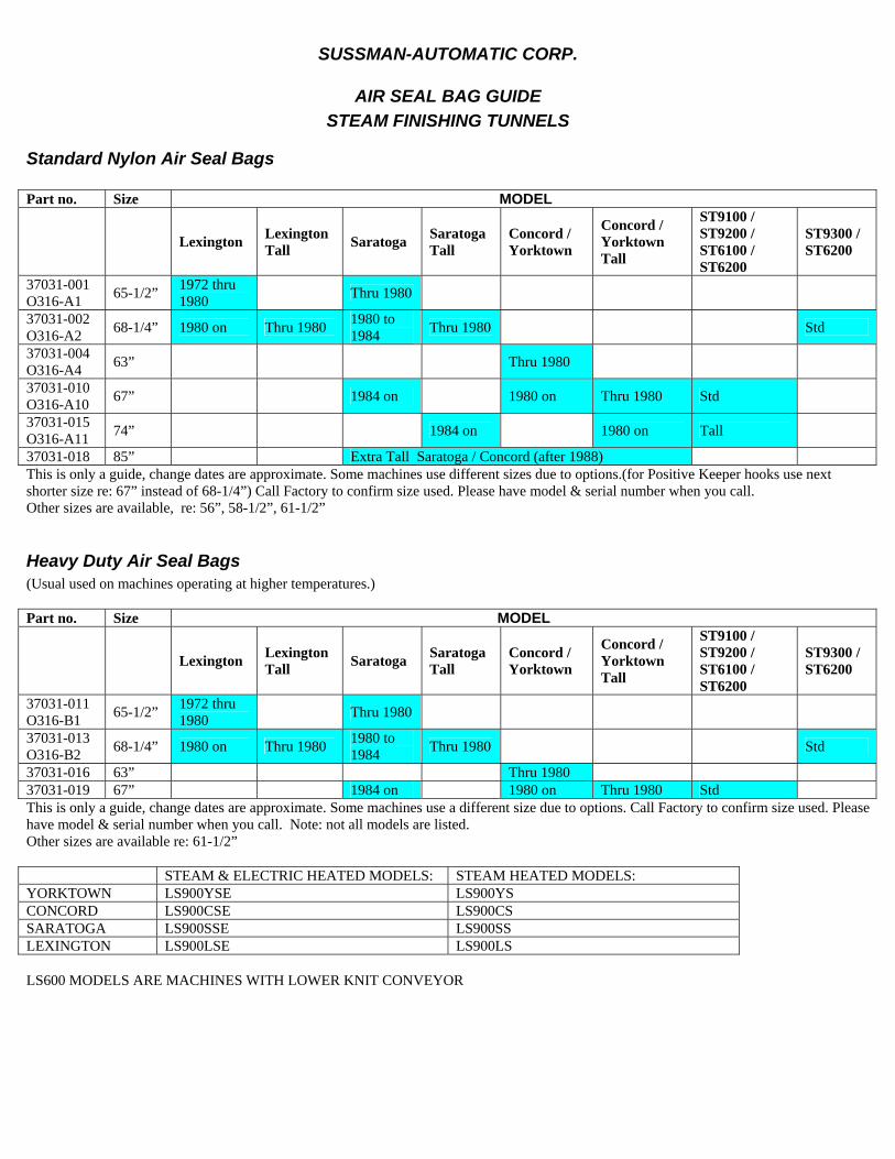
SUSSMAN-AUTOMATIC CORP.
AIR SEAL BAG GUIDE STEAM FINISHING TUNNELS
Standard Nylon Air Seal Bags Part no. Size MODEL
Lexington Lexington Tall Saratoga Saratoga
Tall Concord / Yorktown
Concord / Yorktown Tall
ST9100 / ST9200 / ST6100 / ST6200
ST9300 / ST6200
37031-001 O316-A1 65-1/2” 1972 thru
1980 Thru 1980
37031-002 O316-A2 68-1/4” 1980 on Thru 1980 1980 to
1984 Thru 1980 Std
37031-004 O316-A4 63” Thru 1980
37031-010 O316-A10 67” 1984 on 1980 on Thru 1980 Std
37031-015 O316-A11 74” 1984 on 1980 on Tall
37031-018 85” Extra Tall Saratoga / Concord (after 1988) This is only a guide, change dates are approximate. Some machines use different sizes due to options.(for Positive Keeper hooks use next shorter size re: 67” instead of 68-1/4”) Call Factory to confirm size used. Please have model & serial number when you call. Other sizes are available, re: 56”, 58-1/2”, 61-1/2”
Heavy Duty Air Seal Bags (Usual used on machines operating at higher temperatures.) Part no. Size MODEL
Lexington Lexington Tall Saratoga Saratoga
Tall Concord / Yorktown
Concord / Yorktown Tall
ST9100 / ST9200 / ST6100 / ST6200
ST9300 / ST6200
37031-011 O316-B1 65-1/2” 1972 thru
1980 Thru 1980
37031-013 O316-B2 68-1/4” 1980 on Thru 1980 1980 to
1984 Thru 1980 Std
37031-016 63” Thru 1980 37031-019 67” 1984 on 1980 on Thru 1980 Std This is only a guide, change dates are approximate. Some machines use a different size due to options. Call Factory to confirm size used. Please have model & serial number when you call. Note: not all models are listed. Other sizes are available re: 61-1/2” STEAM & ELECTRIC HEATED MODELS: STEAM HEATED MODELS: YORKTOWN LS900YSE LS900YS CONCORD LS900CSE LS900CS SARATOGA LS900SSE LS900SS LEXINGTON LS900LSE LS900LS LS600 MODELS ARE MACHINES WITH LOWER KNIT CONVEYOR

![VIRGINIA CITY DIRECTORIES AT THE LIBRARY OF … · *BUENA VISTA Lexington, Buena Vista (Rockbridge County, Virginia) City Directory [title varies] – F234 L6 A18 MAIN: 1974, 1976,](https://img.pdfslide.net/doc/110x75/5ad0a7337f8b9ad24f8dec9d/virginia-city-directories-at-the-library-of-buena-vista-lexington-buena-vista.jpg)