Embed Size (px)
Citation preview

Share |
Elliott Sound Products Project 89
Switchmode Power Supply For Car AudioSergio Sánchez Moreno and Rod Elliott
Foreword
This contributed project is a result of considerable collaboration between Sergio and myself, and shouldnot be seen as necessarily a complete project in itself, but a stepping stone to understanding switchingpower supplies, how they work, and what you can do with them.
Be warned - there is considerable risk. Because of the extremely high current available from a carbattery, a tiny mistake may easily lead to catastrophic failure. All electronic components are said to
contain smoke (wire contains an enormous amount), and a slip of the soldering iron can liberate anunbelievable quantity. Seriously though, the risk of severe burns and the possibility of causing a fire inyour car are very real, and should not be underestimated. 300A from a car battery can do a vast
amount of damage in a few milliseconds - should the fuse not blow (you will use a fuse, won't you?),then the damage can be extensive.
At various points in Sergio's part of the article, I have added some of my own information. This is shownin indented small font text.
Please see the special note at the end of this article for important information about the project.
Introduction
The difficulties of installing an HI-FI system in a car are many, although there is no doubt that the mostimportant is the limitation of the vehicle supply voltage. As most readers already know, the nominalvoltage of a car battery is 12V, reaching about 13.8V when charging (i.e., engine running).
The maximum RMS. audio power from a given voltage V is somewhat less than:
Pmax = ( V / ( 2 x 2 ) )2 / R
... where RL is the speaker nominal impedance.
Thus, for a 13.8V system, this power is limited to about 6W on a 4 Ohm load. Note that the lower theresistance of the speaker, the higher the maximum power (this is the reason most audio speakers havea 4 Ohm nominal impedance instead of the more common 8 Ohm in home systems).
This may be simplified to some extent ...
P = (V / 3)2 / RL
and a typical calculation based on a 13.8V supply gives
P = (13.8 / 3)2 / 4
P = 4.62 / 4 = 5.29 Watts
This allows for standard losses, and is acceptably accurate at this voltage - the only real way to know is to
Audio Amplifier Schematic
Search Thousands of Catalogs for Audio Amplifier Schematicwww.globalspec.com
Switchmode Power Supply For Car Audio http://sound.westhost.com/project89.htm
1 de 13 14-04-2011 14:32
measure the amp, since the losses vary depending on the topology of the output stage in particular.
Power output can be increased by a factor of nearly 4 by using bridging techniques, explained in moredetail in ESP project 14, so we can obtain up to about 24W on a 4 Ohm speaker. This can be enoughfor the midrange and high frequencies, but is obviously very limited for a subwoofer application, forexample. (moral: distrust of "4 x 45W" head units is well advised, for they certainly aren't talking aboutRMS power).
So, what can be done to increase available audio power? The answer is a simple derivation of the aboveformula - either decrease load impedance or increase supply voltage. The lower the impedance, the
more current is needed, making the construction of low impedance output stages more difficult (thereare some other practical limits), so let's increase supply voltage.
Switch Mode Power Supply Basics
The vast majority of high-powered audio amplifiers use SMPS (Switch Mode Power Supplies) togenerate higher voltages from the available 12 (13.8) volts. An extensive theoretical explanation on howthese things work is beyond the scope of this article, but these are some fundamental ideas you shouldknow about switch mode power supplies (SMPS) for car amps:
The DC voltage at the battery has to be switched in some form to generate an AC waveformsuitable for a transformer. As you already know, a transformer basically converts the AC voltage inits "primary" to a scaled version of it in its "secondary", the scale factor being the turns ratio of theprimary to the secondary . (Again, take this as an extreme simplification). A transformer doesn'tallow DC voltages to pass, and there is electrical (galvanic) isolation between both windings.
The AC waveform is usually a square wave that is relatively easy and efficient to generate. Thefrequencies usually fall between 25kHz and 100kHz or more, thus allowing smaller transformersthan the used in main appliances (its construction is also different, their cores are not laminated,but made from ferrites or "iron powder"). The switching elements have to be capable of highcurrents and must also be fast and have low switching losses. Usually, power MOSFETs or highspeed bipolar transistors are used (some SMPS designs use SCRs but these are in the minority).
Once this waveform is stepped-up by the transformer, it has to be rectified again and filtered backto DC, since that is what we want. For audio applications, we usually need a symmetrical supply,
+/-35V, for example. The rectification is done with a diode bridge, as it would be using aconventional transformer at 50 or 60 Hz. Note that for the frequencies we are talking about, fast orultra-fast diodes are needed.
If we need a regulated power supply, some kind of feedback must be provided from the outputrails to a controller that can change some parameters of the AC waveform at the primary of thetransformer. This is normally accomplished with PWM (pulse width modulation). We will explainthis later, in the "regulation" paragraph.
Always keep in mind that no energy is created - given a (total) rails to battery voltages ratio, thecurrent drawn from the output will be (at least) be multiplied at the 12V input by the same ratio,thus the total power stays the same (assuming 100% efficiency, and that is never the case). Ageneric transformer "transforms" the voltage by a factor of Tr, current by a factor of 1/Tr, andimpedance at the secondary by a factor of 1/sqr(Tr), Tr being the turns ratio. Impedance is of littleimportance in this context.
A well built SMPS can reach 90% efficiency. So, if you expect to produce +/-35V at 6A (per rail)
supply (this supposes 35x6 + 35x6=360W) then be prepared to draw more than 30A from thebattery! Fortunately, when talking about audio amps reproducing music, power requirements arealways much lower than with pure sine waves.
At this point, the reader should realise the magnitude of the currents involved in a high power SMPS fora car amplifier, and that extreme caution should be taken especially when connecting "the creature" tothe car electrical system.
Switchmode Power Supply For Car Audio http://sound.westhost.com/project89.htm
2 de 13 14-04-2011 14:32
The system
The present project describes the construction of a flexible SMPS capable of delivering powers in theorder of 350W continuously, depending on the transformer used. The output voltage depends mainlyon the turns ratio of the primary and secondary windings, but may be adjusted to a somewhat lowervalue using regulation. This should be enough to power a 200W subwoofer amplifier plus perhaps 2stereo amps for the mids and highs.
It is part of a complete car amp that I have built, with 6 power stages based on National's LM3886Overture Amplifier. They can be combined into one >250W/4 Ohm subwoofer channel plus 2 x 65W/4Ohm mid+high channels, alternatively into 2 x 120W/4 Ohm + 2 x 65W or even to form a multichannel 6
x 65W/4 Ohm amplifier, so it is an extremely flexible and high-powered system without renouncingsound quality. The parallel bridging techniques needed to do this will be possibly described in anotherproject.
Construction of the SMPS
The complete schematic of the SMPS is shown below.
Note: This is Sergio's original version of the supply, the one shown in Figure 9 is likely to be the most commonly
used, as it is somewhat simpler, but has virtually identical performance. [esp]
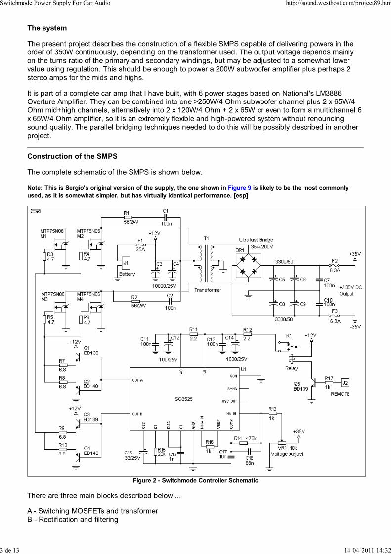
Figure 2 - Switchmode Controller Schematic
There are three main blocks described below ...
A - Switching MOSFETs and transformerB - Rectification and filtering
Switchmode Power Supply For Car Audio http://sound.westhost.com/project89.htm
3 de 13 14-04-2011 14:32
C - Control circuitry
A - Switching MOSFETs and TransformerThe selected switching topology is called a "push-pull" converter, because the transformer has a doubleprimary (or a "centre-tapped" one, if your prefer). The centre tap is permanently connected to the carbattery (via an LC filter to avoid creating peaks in the battery lines, which could affect other electronicequipment in the car). The two ends of the primary are connected to a pair of paralleled MOSFETs eachthat tie them to ground in each conduction cycle (Vgs of the corresponding MOSFET high).
These MOSFETs should be fast, able to withstand high currents (in excess of 30A each if possible) andhave the lowest possible Rds(on). The proposed On-Semiconductor's MTP75N06 can withstand 75Amp
and has a Rds(on) below 10 milliohm. This is important, because the lower this resistance is, the lesspower they are going to dissipate when switching with a square waveform. Another alternatives areMTP60N06, or the more popular BUZ11 and IRF540.
Although the schematics show a previous bipolar push-pull stage, you can also connect the gateresistor directly to the output of the controlling IC, leaving out the transistors, as the SG3525 is capableto drive up to 500 mA (theoretically), more than enough to switch the MOSFETs fast.
B - Rectification and FilteringIf one looks to the secondary side of the SMPS, it resembles exactly the scheme of a typical mainsPSU, with one fundamental difference - the switching diodes have to be FAST or ULTRAFAST, if youuse a standard diode bridge the system will simply blow up (and this can be very impressive, believeme!) Although a diode bridge is represented, it can be made with discrete diodes as well. Use highcurrent (10 A minimum and a suitable voltage rating) diodes. I recommend using 4 x TO220 doublediodes that can be paralleled to form a single one in each package.
You may be surprised that the capacitors aren't too big. This is due to the high switching frequency. It isimportant that they are good quality ones and must be rated for 105 degrees operation. Ripple currentrating and low ESR (equivalent series resistance) is very important for any switching supply. In my
opinion, 5000uF per rail is enough.
C - Control CircuitryThe controller IC is an SG3525. It comprises all the necessary subsystems to generate a fixedfrequency, compare with a reference to modulate its pulse width and drive two outputs withoutoverlapping. It works from 8 to 35V and filtering in the supply is recommended, as shown. As stated
above, you can connect the outputs directly to the gate resistors of the MOSFETs if you don't want toinclude the bipolar stages.
The resistor RT and capacitor CT fix the oscillation frequency. Experimentation showed me that about35kHz produces good results with my transformer. Another capacitor, Css fixes the "slow start" time -when you turn on the system, the pulse width increases from 0 up to the steady value, thus limiting the"inrush" current, a very good feature to avoid "thumps" in the speaker and protect the electricalinstallation. It has also a shutdown pin that allows control of the SMPS from an external signal(REMOTE from the head unit, for example).
In this project, layout is critical, incorrect track widths or excessively long traces can have highinductances and produce peaks that can make the MOSFETs blow up. ESP will probably offer asuitable PCB layout if there is enough interest in it.
Transformer Construction Details
This is the most critical part of the design, and you have two options, buying a commercial unit with therequired power rating and turns ratio (hard to find, only a single supplier found at the time of writing), or
wind your own.
If you choose to wind your own transformer (as if you have much choice), you have to decide which
shape of core to use. The preferred material is ferrite, which has high permeability (ability to "conduct"magnetic flux) or iron powder, which has a lower permeability, but is less likely to saturate. Mostcommercial transformers use ferrite, and iron powder is generally the best material for filter chokes
Switchmode Power Supply For Car Audio http://sound.westhost.com/project89.htm
4 de 13 14-04-2011 14:32
(inductors) that carry substantial DC.
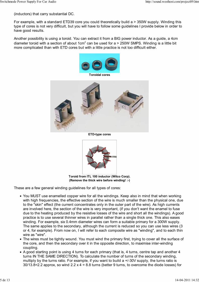
For example, with a standard ETD39 core you could theoretically build a > 350W supply. Winding thistype of cores is not very difficult, but you will have to follow some guidelines I provide below in order tohave good results.
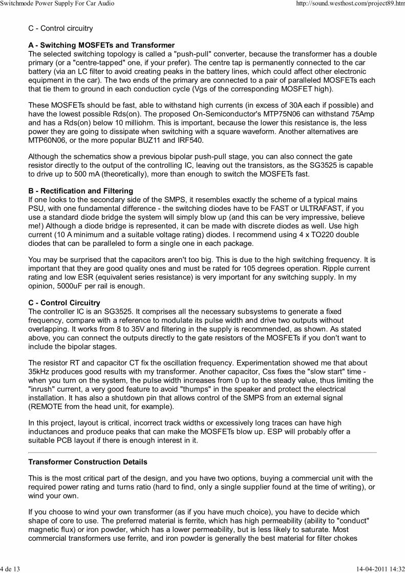
Another possibility is using a toroid. You can extract it from a BIG power inductor. As a guide, a 4cm
diameter toroid with a section of about 1cm2 can be used for a > 250W SMPS. Winding is a little bitmore complicated than with ETD cores but with a little practice is not too difficult either.
Toroidal cores
ETD-type cores
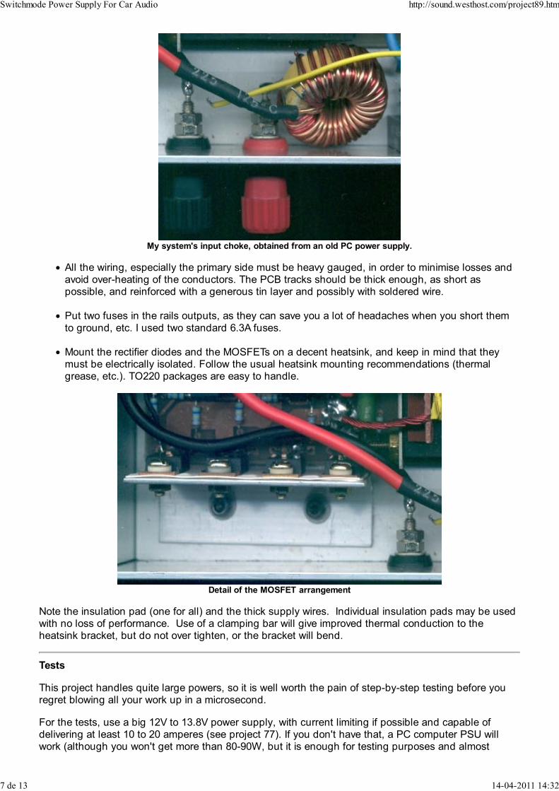
Toroid from ITL 100 inductor (Wilco Corp).
(Remove the thick wire before winding! :-)
These are a few general winding guidelines for all types of cores:
You MUST use enamelled copper wire for all the windings. Keep also in mind that when workingwith high frequencies, the effective section of the wire is much smaller than the physical one, dueto the "skin" effect (the current concentrates only in the outer part of the wire). As high currentsare involved here, the section of the wire is very important, (if you don't want the enamel to fusedue to the heating produced by the resistive losses of the wire and short all the windings). A good
practice is to use several thinner wires in parallel rather than a single thick one. This also easeswinding. For example, six 0.4mm diameter wires can form a suitable primary for a 300W supply.The same applies to the secondary, although the current is reduced so you can use less wires (3or 4, for example). From now on, I will refer to each composite wire as "winding", and to each thinwire as "wire".The wires must be tightly wound. You must wind the primary first, trying to cover all the surface ofthe core, and then the secondary over it in the opposite direction, to maximise inter-windingcoupling.A good starting point is using 4 turns for each primary (that is, 4 turns, centre tap and another 4
turns IN THE SAME DIRECTION). To calculate the number of turns of the secondary winding,multiply by the turns ratio. For example, if you want to build a +/-30V supply, the turns ratio is30/13.8=2.2 approx, so wind 2.2 x 4 = 8.8 turns (better 9 turns, to overcome the diode losses) for
Switchmode Power Supply For Car Audio http://sound.westhost.com/project89.htm
5 de 13 14-04-2011 14:32

each secondary (that is, again, 9 turns, centre tap and another 9 turns IN THE SAMEDIRECTION).
To start winding, take the number of thin wires you have decided to use (6, for example) in theprimary, all together. Leave about 3 or 4 cm out of the core to ease connection to the board andstart winding. When you have wound 4 COMPLETE turns, go out the core and cut at 3 or 4 cm.Now you have the first primary. Then start again IN THE SAME DIRECTION winding the other 4turns and at the end leave another 3 or 4 cm for connection. Twist together the thin wires of eachwinding at the ends, to ease soldering.
The varnish of the wire is intended to provide electrical isolation, so you have to remove it at the
ends to make the connections to the board. Be sure to remove about 1cm to the end in ALL thewires you use. You can do that using a special solvent or with sandpaper and a lot of patienceBEFORE winding.
The following are photos of two models of transformers. The left one is a toroidal I wound myself usingthe core from a big inductor from Wilco Corporation (ITL-501), and the right one is a commercial unitfrom a US manufacturer (2x3:1, 350W). Both worked similarly.
Left - Home Made Transformer. Commercial Transformer - Right
Other remarks
The relay allows disconnecting of the power supply with the REMOTE (or "Electrical Antenna"
from the head unit. Power consumption when off is then only the gate currents of the MOSFETs (Afew nA) and the base current of the transistor that controls the relay (a few uA). Nothing to worryabout, certainly.
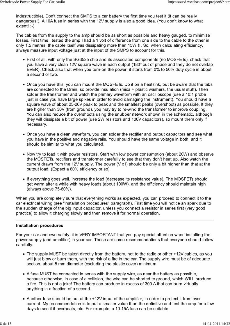
Connect a big choke in series with the supply, as this will eliminate the switching noise that couldinterfere with other electrical equipment. You can use the toroid that filters the +5V output of a oldPC supply. (see figure below)
Switchmode Power Supply For Car Audio http://sound.westhost.com/project89.htm
6 de 13 14-04-2011 14:32
My system's input choke, obtained from an old PC power supply.
All the wiring, especially the primary side must be heavy gauged, in order to minimise losses andavoid over-heating of the conductors. The PCB tracks should be thick enough, as short aspossible, and reinforced with a generous tin layer and possibly with soldered wire.
Put two fuses in the rails outputs, as they can save you a lot of headaches when you short them
to ground, etc. I used two standard 6.3A fuses.
Mount the rectifier diodes and the MOSFETs on a decent heatsink, and keep in mind that theymust be electrically isolated. Follow the usual heatsink mounting recommendations (thermalgrease, etc.). TO220 packages are easy to handle.
Detail of the MOSFET arrangement
Note the insulation pad (one for all) and the thick supply wires. Individual insulation pads may be usedwith no loss of performance. Use of a clamping bar will give improved thermal conduction to theheatsink bracket, but do not over tighten, or the bracket will bend.
Tests
This project handles quite large powers, so it is well worth the pain of step-by-step testing before youregret blowing all your work up in a microsecond.
For the tests, use a big 12V to 13.8V power supply, with current limiting if possible and capable ofdelivering at least 10 to 20 amperes (see project 77). If you don't have that, a PC computer PSU willwork (although you won't get more than 80-90W, but it is enough for testing purposes and almost
Switchmode Power Supply For Car Audio http://sound.westhost.com/project89.htm
7 de 13 14-04-2011 14:32
indestructible). Don't connect the SMPS to a car battery the first time you test it (it can be reallydangerous!). A 10A fuse in series with the 12V supply is also a good idea. (You don't know to whatextent! ;-)
The cables from the supply to the amp should be as short as possible and heavy gauged, to minimise
losses. First time I tested the amp I had a 1 volt of difference from one side to the cable to the other inonly 1.5 metres: the cable itself was dissipating more than 15W!!!. So, when calculating efficiency,always measure input voltage just at the input of the SMPS to account for this.
First of all, with only the SG3525 chip and its associated components (no MOSFETs), check thatyou have a very clean 12V square wave in each output (180º out of phase and they do not overlapEVER). Check also that when you turn-on the power, it starts from 0% to 50% duty cycle in abouta second or two.
Once you have this, you can mount the MOSFETs. Do it on a heatsink, but be aware that the tabsare connected to the Drain, so provide insulation (mica + plastic washers, the usual stuff). Then
solder the transformer and watch the primary waveform with an oscilloscope (use a 10:1 probejust in case you have large spikes in order to avoid damaging the instrument). You should have asquare wave of about 25-26V peak to peak and the smallest peaks (overshoot) as possible. It theyare higher than 30V (from ground), you may try to re-wind the transformer to improve coupling.You can also reduce the overshoots using the snubber network shown in the schematic, althoughthey will dissipate a bit of power (use 2W resistors and 100V capacitors), so mount them only ifnecessary.
Once you have a clean waveform, you can solder the rectifier and output capacitors and see what
you have in the positive and negative rails. You should have the same voltage in both, and itshould be similar to what you calculated.
Now try to load it with power resistors. Start with low power consumption (about 20W) and observethe MOSFETs, rectifiers and transformer carefully to see that they don't heat up. Also watch thecurrent drawn from the 12V supply. The power (V x I) should be only a bit higher than that at theoutput load. (Expect a 80% efficiency or so).
If everything goes well, increase the load (decrease its resistance value). The MOSFETs shouldget warm after a while with heavy loads (about 100W), and the efficiency should maintain high(always above 75-80%).
When you are completely sure that everything works as expected, you can proceed to connect it to thecar electrical wiring (see "installation procedures" paragraph). First time you will notice an spark due tothe sudden charge of the big input capacitor, unless you connect a resistor in series first (very goodpractice) to allow it charging slowly and then remove it for normal operation.
Installation procedures
For your car and own safety, it is VERY IMPORTANT that you pay special attention when installing thepower supply (and amplifier) in your car. These are some recommendations that everyone should followcarefully:
The supply MUST be taken directly from the battery, not to the radio or other +12V cables, as youwill just blow or burn them, with the risk of a fire in the car. The supply wire must be of adequatesection, about 5 mm diameter (excluding the plastic cover) minimum.
A fuse MUST be connected in series with the supply wire, as near the battery as possible,because otherwise, in case of a collision, the wire can be shorted to ground, which WILL producea fire. This is not a joke! The battery can produce in excess of 300 A that can burn virtuallyanything in a fraction of a second.
Another fuse should be put at the +12V input of the amplifier, in order to protect it from overcurrent. My recommendation is to put a smaller value than the definitive and test the amp for a fewdays to see if it overheats, etc. For example, a 10-15A fuse can be suitable.
Switchmode Power Supply For Car Audio http://sound.westhost.com/project89.htm
8 de 13 14-04-2011 14:32
The FIRST connection you have to make to the amp is Ground, and that must be firmly screwedto the car chassis as near the amp as possible with thick wire. Notice that, if you connected, for
example, the signal RCA cables first and then the +12V wire, the input capacitors would try tocharge returning to ground via the audio cables, possibly ruining the preamplifier of the head unit.
Regulating the Power Supply
The project itself has excellent load regulation, and the rails voltage is almost only determined by theturns ratio, but it has inherently zero line regulation (basically, it "simply" multiplies the input voltage bythe turns ratio), although this is not a problem in a car, where the battery voltage remains essentiallyconstant.
If the obtained output voltages are very high and you can't (or don't want to) modify the windings, youcan use regulation to lower them a bit. For example, I use a 3:1 transformer that would give about+/-38V without regulation that is unacceptable for my LM3886 stages to be safe, so I have regulated to+/-26V. The MOSFETs will suffer more, however, so regulate the supply only if strictly necessary.
You can install the feedback potentiometer and set it in order to have zero reference voltage todeactivate regulation, or increase its value to regulate to the desired voltage.
NOTE: Regulation will work better with output inductors just between the rectifier diodes and the outputcapacitors. 10 to 100 uH with iron powder core and at least 8A current rating can be adequate. (I don'tuse them and my supply works reliably, although I never put it to the power limits). You can also
improve safety by paralleling more MOSFETs, so the current through them is shared. This alsoimproves efficiency a bit, as the total Rds(on) is reduced.
Obtaining +/-12V from the SMPS for Preamplifiers
If you need to power opamps for a crossover, equaliser or preamplifier, you can obtain a symmetrical+/-12V (for example) from the main supply rails, simply with a resistor, zener and capacitor. (see Figure1 of Project 27). Remember to use 1 or 2W resistors and zener diodes. You can obtain about 25-50 mAfrom this without problems.
Additional Information
The following material is from ESP - there are some suggestions and additional information, as well as asimplified version of the SMPS.
Although my version of the switcher is simplified, this does not imply that performance is lower thanSergio's original, but is the result of my own experiments and tests. We may be on opposite sides ofthe planet, but there was considerable collaboration during the development of the supply, and I havebuilt and tested the version shown below.
MOSFETs and Thermal Runaway
It has been claimed that MOSFETs are immune from thermal runaway, since they have a positivetemperature coefficient for their "on" resistance. While this may be partially true for a Class-AB poweramplifier, it is completely false for a switching supply.
For example, a push pull SMPS using one IRF540 MOSFET a side draws 30A at full load. If we checkthe data sheet, we find that Rds(on) is 0.044 Ohm (44 millohms) at 25 degrees C, then we know that it
will generate
P=I² x R = 30%sup2; x 0.044 = 900 x 0.044 = 39 W peak (per transistor).
At 50 degrees (not uncommon in a car that has been in the sun for some time), Rds(on) will be about
1.25 times the value at 25 degrees (this is from the datasheet), or 0.055 ohms. Power dissipation willnow be 49W, so the heatsink has to dispose of more heat. We can guarantee that the extra heat will
Switchmode Power Supply For Car Audio http://sound.westhost.com/project89.htm
9 de 13 14-04-2011 14:32
cause the heatsink temperature to rise further, which will increase Rds(on), and that will make theheatsink hotter, and - BANG
Ensuring that you use parallel devices and a good heatsink will reduce the likelihood of thisdramatically. Two MOSFETs sharing the load will dissipate 1/4 the power (each) of a single device, and
have a lower thermal resistance to the heatsink as well.
P=I² x R = 15² x 0.044 = 225 x 0.044 = 9.9 W peak (per transistor) - 19.8 W for both
The power shown per transistor is the peak - actual (RMS) power (per device) is half that calculated.
The total power dissipated by both transistors (or sets of transistors in the case of paralleled devices) isthe full value shown, since when one device is "on", the other is "off" and vice versa.
Naturally, the maximum dissipation will only occur at maximum (continuous) amplifier power - the real
life requirements are usually somewhat less, however, it is essential that the design is capable ofcontinuous "worst case" dissipation to ensure an adequate safety margin.
I strongly recommend that you do the calculations yourself, and make sure that you understand theimplications.
Regulation
Normally, one would expect regulation as shown in Figure 1, however, using the feedback input of thecontroller IC relies rather too heavily on the impedance of the DC supply lines. Normally, outputinductors are used (with an additional "flyback" diode) to provide a pulse width to voltage converter. The majority of commercial systems seem to use a non-regulated converter, so I would consider thatthis will be quite acceptable in practice. Tests so far have shown that with a load of about 150 Watts,the regulation was almost entirely dependent on the voltage drop in the supply line!
As well as being unregulated, there are a couple of other changes in the circuit. R8 (100 Ohms) isconnected between the timing capacitor and discharge pins of the controller IC. This introduces a"dead time" where both outputs are turned off, and the reason for this is to ensure that the powerMOSFET pairs can never be switched on at the same time - should this happen, a very large current
will flow (albeit for only a microsecond or less). Since I did not use the extra switching transistors andused higher value gate resistors, the dead time is important.
I also increased the switching frequency. As shown, the internal oscillator runs at approximately 50kHz(my prototype actually runs at 54kHz), where Sergio's original was designed for 35kHz switching. Thedifference is determined by the resistor on the RT pin of the controller, in my case, 12k.
Regulation will obviously make the circuit much more complicated, and as stated above, my version isunregulated. This will maintain maximum efficiency, and also reduces the dependence on the outputfilter capacitors - they are effectively fed with almost pure DC from the rectifier at all loads, so storagetime is not an issue. Relatively small filter capacitors can be used, and the output will still be quiteclean.
Not surprisingly, the turns ratio is very important if regulation is not used. Assume an input voltage of12V to allow for losses. To obtain +/-24V, the turns ratio is 1:2 - for each turn on the primary, there willbe 2 turns on the secondary. This is the same as Sergio's description, and the same rules apply.
Unlike a normal mains transformer supplied with a sinewave, the switching waveform is a squarewave,so the peak and RMS values are the same (in other words, there is no 1.414 conversion as would be thecase with a mains frequency transformer). The problem with this is that the 12V assumed at full loadwill be 13.8V under light or normal loading, so the voltage will be higher than expected. Using thesame transformer as above (1:2 turns ratio) the no-load output voltage will be 27.6 volts - make surethat you do not exceed the voltage rating of the amplifier!
Switchmode Power Supply For Car Audio http://sound.westhost.com/project89.htm
10 de 13 14-04-2011 14:32
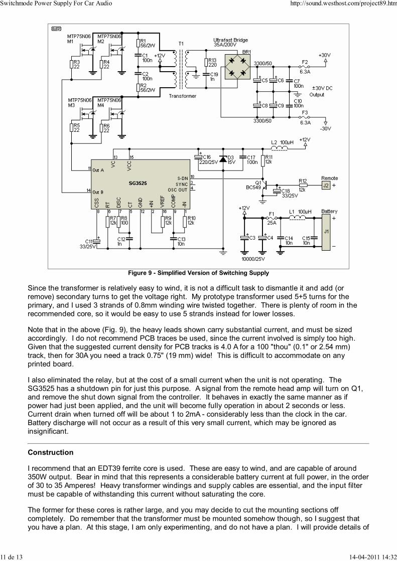
Figure 9 - Simplified Version of Switching Supply
Since the transformer is relatively easy to wind, it is not a difficult task to dismantle it and add (orremove) secondary turns to get the voltage right. My prototype transformer used 5+5 turns for theprimary, and I used 3 strands of 0.8mm winding wire twisted together. There is plenty of room in therecommended core, so it would be easy to use 5 strands instead for lower losses.
Note that in the above (Fig. 9), the heavy leads shown carry substantial current, and must be sizedaccordingly. I do not recommend PCB traces be used, since the current involved is simply too high. Given that the suggested current density for PCB tracks is 4.0 A for a 100 "thou" (0.1" or 2.54 mm)
track, then for 30A you need a track 0.75" (19 mm) wide! This is difficult to accommodate on anyprinted board.
I also eliminated the relay, but at the cost of a small current when the unit is not operating. TheSG3525 has a shutdown pin for just this purpose. A signal from the remote head amp will turn on Q1,and remove the shut down signal from the controller. It behaves in exactly the same manner as ifpower had just been applied, and the unit will become fully operation in about 2 seconds or less. Current drain when turned off will be about 1 to 2mA - considerably less than the clock in the car. Battery discharge will not occur as a result of this very small current, which may be ignored asinsignificant.
Construction
I recommend that an EDT39 ferrite core is used. These are easy to wind, and are capable of around350W output. Bear in mind that this represents a considerable battery current at full power, in the orderof 30 to 35 Amperes! Heavy transformer windings and supply cables are essential, and the input filter
must be capable of withstanding this current without saturating the core.
The former for these cores is rather large, and you may decide to cut the mounting sections off
completely. Do remember that the transformer must be mounted somehow though, so I suggest thatyou have a plan. At this stage, I am only experimenting, and do not have a plan. I will provide details of
Switchmode Power Supply For Car Audio http://sound.westhost.com/project89.htm
11 de 13 14-04-2011 14:32

the solution when I actually have one.
All of Sergio's previous comments apply to this version, so make sure that you read his materialthoroughly. I do not propose to cover the same instructions again, since Sergio has already done anexcellent job.
Prototype Testing
I have done some initial tests, but have not yet connected the bridge and output capacitors. With whatwas intended to be 12+12 turns on the secondary, I obtained an acceptably clean waveform with some
overshoot with the secondary unloaded. Output voltage was about 38V peak, so I obviously had onemore turn than I thought I did (input voltage was 14V DC). I cannot stress highly enough that thewinding process is critical to the success of your transformer, and you should expect to have a couple ofattempts before you get it exactly right. The small number of turns needed makes this much easierthan would otherwise be the case.
During my testing, my power supply and load became very warm indeed, but the MOSFETs (I usedIRF540s) remained cool, even though they were mounted on a rather small heatsink lying on my
workbench. This indicates that the heatsinking requirements are easily achievable, but does not meanthat you can be lax with mounting. My transformer also remained cool, with no sign of the core orwindings getting even warm. This must be considered a design goal. Even the lead I used to my loadbecame warm, so the power output was very real indeed!
You will need an oscilloscope (or at least access to one) or the project will be very much harder to buildand test. A design such as this relies on careful measurements and great care to make certain that itwill perform as expected. Attempting this without an oscilloscope is not recommended.
Please Note:
This project has already created far more questions via e-mail than I desired or expected. For everyone
who plans on making this supply ... you are essentially on your own. I cannot (and will not) be drawninto lengthy e-mail exchanges if you cannot make the supply work.
That it does work if built as described is certain, that you will be able to achieve the same results is not.
If you do not have (or at least have access to) an oscilloscope - don't even think about trying to makethe supply, as it will not be possible to ensure that the duty cycle of the controller is exactly 50%, or thatthere is no severe overshoot or ringing at the output.
Please do not not send me e-mails asking for help. I will simply refer you to this paragraph - I cannotdiagnose your problems via mail, and will not even try. It is entirely up to the constructor to determinehis/ her abilities before starting.
The construction of any switching supply is fraught with difficulties, risks (including but not limited toelectrocution!) and problems that need to be addressed. They are not simple (despite appearances) oreasy, and there are a great many things that can go wrong. If you are not 100% confident that youunderstand the issues involved, please do yourself a favour and build something else instead.
Projects Index
Main Index
Copyright Notice. This article, including but not limited to all text and diagrams, is the intellectual property of Sergio Sánchez
Moreno and Rod Elliott, and is Copyright © 2002. Reproduction or re-publication by any means whatsoever, whether
electronic, mechanical or electro- mechanical, is strictly prohibited under International Copyright laws. The authors (Sergio
Sánchez Moreno and Rod Elliott) grant the reader the right to use this information for personal use only, and further allow that
Inductorless DC/DC
Step-Up, Step-Down or Inverting Small Size and High Efficiency!www.linear.com
Switchmode Power Supply For Car Audio http://sound.westhost.com/project89.htm
12 de 13 14-04-2011 14:32

one (1) copy may be made for reference while constructing the project. Commercial use is prohibited without express written
authorisation from Sergio Sánchez Moreno and Rod Elliott.
Page Created and Copyright © Sergio Sánchez Moreno/ Rod Elliott 21 Apr 2002./ Added special note 31 Oct 2002.
Switchmode Power Supply For Car Audio http://sound.westhost.com/project89.htm
13 de 13 14-04-2011 14:32