Embed Size (px)
Citation preview
Switched capacitor circuitry
This worksheet and all related files are licensed under the Creative Commons Attribution License,version 1.0. To view a copy of this license, visit http://creativecommons.org/licenses/by/1.0/, or send aletter to Creative Commons, 559 Nathan Abbott Way, Stanford, California 94305, USA. The terms andconditions of this license allow for free copying, distribution, and/or modification of all licensed works bythe general public.
Resources and methods for learning about these subjects (list a few here, in preparation for yourresearch):
1
Question 1
Write an equation describing the precise mathematical relationship between electric charge (Q),capacitance (C), and voltage (V ).
file 01454
Answer 1
All I’ll reveal here is that charge is directly proportional to both voltage and capacitance. This equationis an easy one to find on your own, by researching through various electronics textbooks!
Follow-up question: calculate the amount of charge stored in a 330 µF capacitor charged with a voltageof 12 volts.
Notes 1
This is one of those equations usually discussed somewhere in the first few months of basic electronicseducation, and promptly forgotten by most. It can be very useful, however, when dealing with charge pumpsand other switched-capacitor circuitry.
2
Question 2
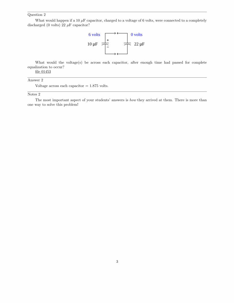
What would happen if a 10 µF capacitor, charged to a voltage of 6 volts, were connected to a completelydischarged (0 volts) 22 µF capacitor?
10 µF 22 µF
6 volts 0 volts
What would the voltage(s) be across each capacitor, after enough time had passed for completeequalization to occur?
file 01453
Answer 2
Voltage across each capacitor = 1.875 volts.
Notes 2
The most important aspect of your students’ answers is how they arrived at them. There is more thanone way to solve this problem!
3
Question 3
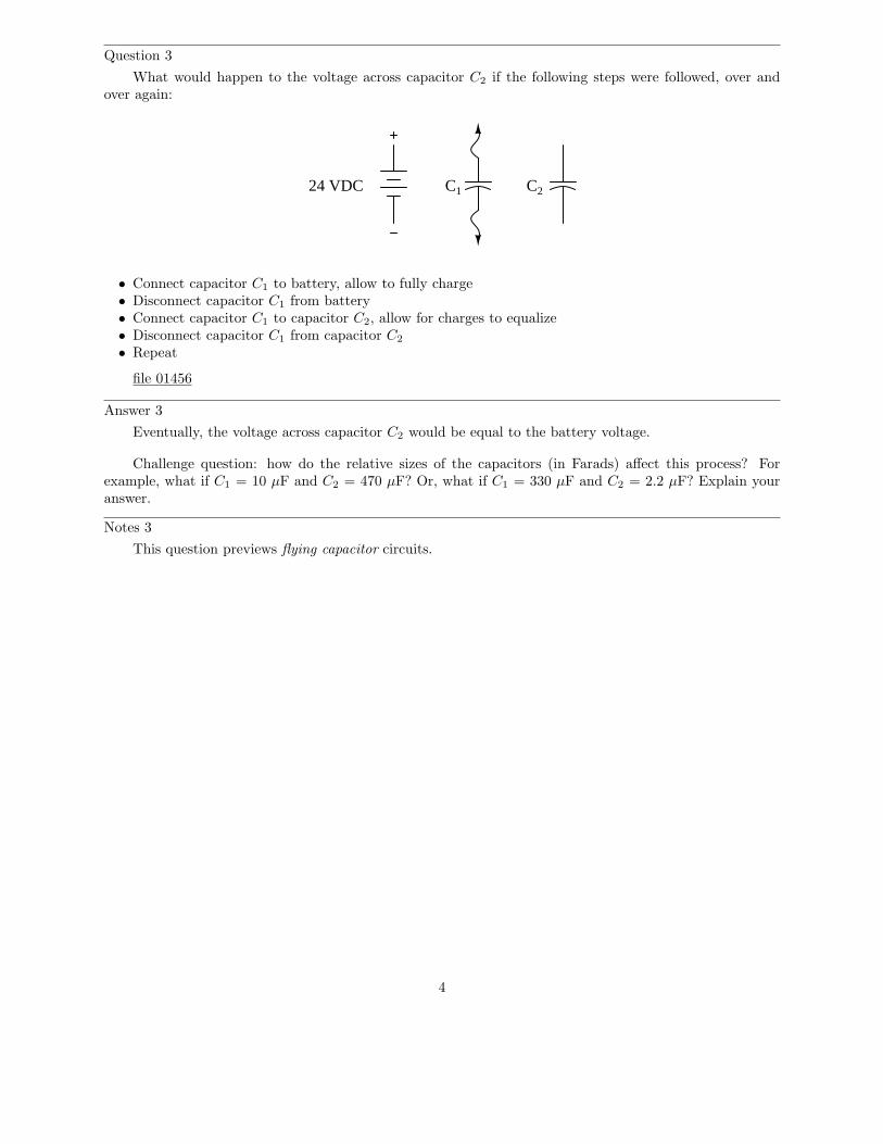
What would happen to the voltage across capacitor C2 if the following steps were followed, over andover again:
24 VDC C1 C2
• Connect capacitor C1 to battery, allow to fully charge• Disconnect capacitor C1 from battery• Connect capacitor C1 to capacitor C2, allow for charges to equalize• Disconnect capacitor C1 from capacitor C2
• Repeat
file 01456
Answer 3
Eventually, the voltage across capacitor C2 would be equal to the battery voltage.
Challenge question: how do the relative sizes of the capacitors (in Farads) affect this process? Forexample, what if C1 = 10 µF and C2 = 470 µF? Or, what if C1 = 330 µF and C2 = 2.2 µF? Explain youranswer.
Notes 3
This question previews flying capacitor circuits.
4
Question 4
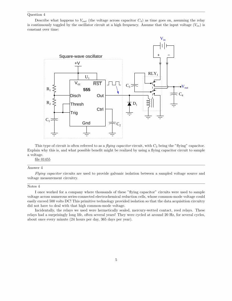
Describe what happens to Vout (the voltage across capacitor C4) as time goes on, assuming the relayis continuously toggled by the oscillator circuit at a high frequency. Assume that the input voltage (Vin) isconstant over time:
555Disch
Thresh
Trig
Gnd
Vcc RST
Out
Ctrl
+V
Vout
Vin
C1
R1
R2
C2
C3
C4
D1
RLY1U1
Square-wave oscillator
This type of circuit is often referred to as a flying capacitor circuit, with C3 being the ”flying” capacitor.Explain why this is, and what possible benefit might be realized by using a flying capacitor circuit to samplea voltage.
file 01455
Answer 4
Flying capacitor circuits are used to provide galvanic isolation between a sampled voltage source andvoltage measurement circuitry.
Notes 4
I once worked for a company where thousands of these ”flying capacitor” circuits were used to samplevoltage across numerous series-connected electrochemical reduction cells, whose common-mode voltage couldeasily exceed 500 volts DC! This primitive technology provided isolation so that the data acquisition circuitrydid not have to deal with that high common-mode voltage.
Incidentally, the relays we used were hermetically sealed, mercury-wetted contact, reed relays. Theserelays had a surprisingly long life, often several years! They were cycled at around 20 Hz, for several cycles,about once every minute (24 hours per day, 365 days per year).
5
Question 5
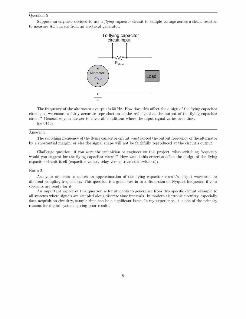
Suppose an engineer decided to use a flying capacitor circuit to sample voltage across a shunt resistor,to measure AC current from an electrical generator:
Alternator
Rshunt
To flying capacitorcircuit input
Load
The frequency of the alternator’s output is 50 Hz. How does this affect the design of the flying capacitorcircuit, so we ensure a fairly accurate reproduction of the AC signal at the output of the flying capacitorcircuit? Generalize your answer to cover all conditions where the input signal varies over time.
file 01458
Answer 5
The switching frequency of the flying capacitor circuit must exceed the output frequency of the alternatorby a substantial margin, or else the signal shape will not be faithfully reproduced at the circuit’s output.
Challenge question: if you were the technician or engineer on this project, what switching frequencywould you suggest for the flying capacitor circuit? How would this criterion affect the design of the flyingcapacitor circuit itself (capacitor values, relay versus transistor switches)?
Notes 5
Ask your students to sketch an approximation of the flying capacitor circuit’s output waveform fordifferent sampling frequencies. This question is a great lead-in to a discussion on Nyquist frequency, if yourstudents are ready for it!
An important aspect of this question is for students to generalize from this specific circuit example toall systems where signals are sampled along discrete time intervals. In modern electronic circuitry, especiallydata acquisition circuitry, sample time can be a significant issue. In my experience, it is one of the primaryreasons for digital systems giving poor results.
6
Question 6
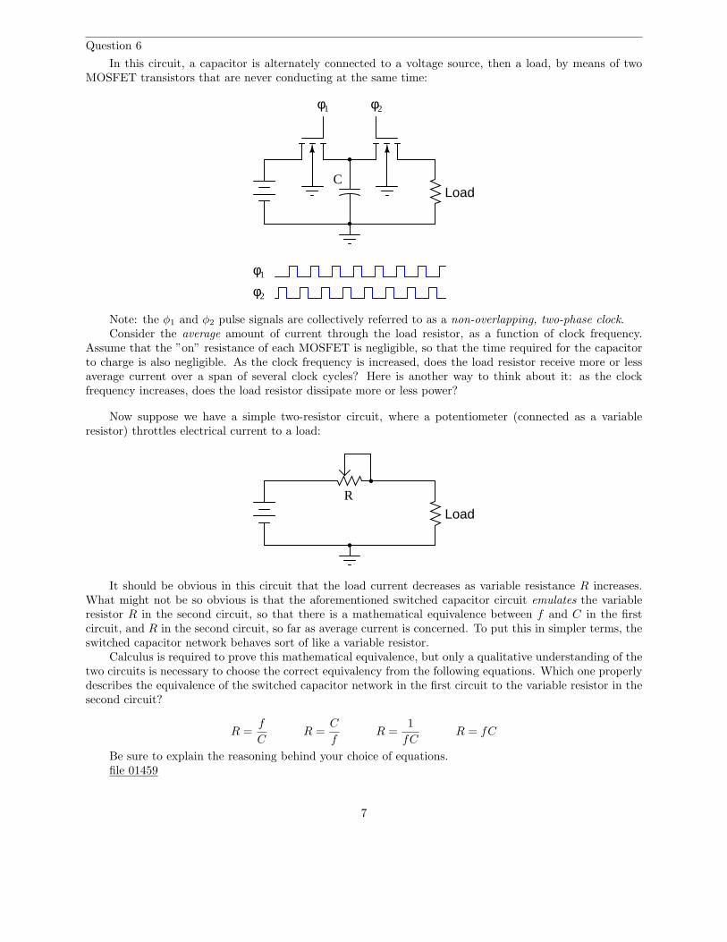
In this circuit, a capacitor is alternately connected to a voltage source, then a load, by means of twoMOSFET transistors that are never conducting at the same time:
φ1 φ2
CLoad
φ1
φ2
Note: the φ1 and φ2 pulse signals are collectively referred to as a non-overlapping, two-phase clock.Consider the average amount of current through the load resistor, as a function of clock frequency.
Assume that the ”on” resistance of each MOSFET is negligible, so that the time required for the capacitorto charge is also negligible. As the clock frequency is increased, does the load resistor receive more or lessaverage current over a span of several clock cycles? Here is another way to think about it: as the clockfrequency increases, does the load resistor dissipate more or less power?
Now suppose we have a simple two-resistor circuit, where a potentiometer (connected as a variableresistor) throttles electrical current to a load:
LoadR
It should be obvious in this circuit that the load current decreases as variable resistance R increases.What might not be so obvious is that the aforementioned switched capacitor circuit emulates the variableresistor R in the second circuit, so that there is a mathematical equivalence between f and C in the firstcircuit, and R in the second circuit, so far as average current is concerned. To put this in simpler terms, theswitched capacitor network behaves sort of like a variable resistor.
Calculus is required to prove this mathematical equivalence, but only a qualitative understanding of thetwo circuits is necessary to choose the correct equivalency from the following equations. Which one properlydescribes the equivalence of the switched capacitor network in the first circuit to the variable resistor in thesecond circuit?
R =f
CR =
C
fR =
1
fCR = fC
Be sure to explain the reasoning behind your choice of equations.file 01459
7
Answer 6
Average load current increases as clock frequency increases: R = 1fC
Notes 6
Perhaps the most important aspect of this question is students’ analytical reasoning: how did theyanalyze the two circuits to arrive at their answers? Be sure to devote adequate class time to a discussion ofthis, helping the weaker students grasp the concept of switched-capacitor/resistor equivalency by allowingstronger students to present their arguments.
8
Question 7
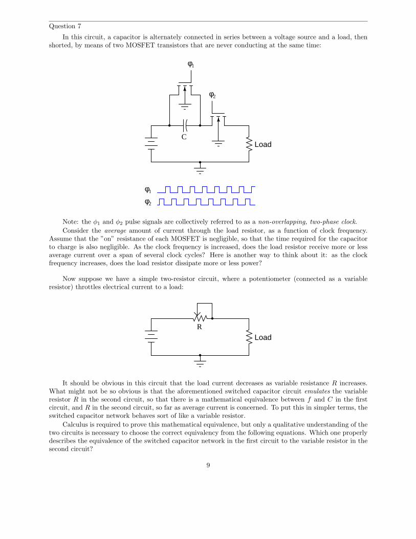
In this circuit, a capacitor is alternately connected in series between a voltage source and a load, thenshorted, by means of two MOSFET transistors that are never conducting at the same time:
φ1
φ2
CLoad
φ1
φ2
Note: the φ1 and φ2 pulse signals are collectively referred to as a non-overlapping, two-phase clock.
Consider the average amount of current through the load resistor, as a function of clock frequency.Assume that the ”on” resistance of each MOSFET is negligible, so that the time required for the capacitorto charge is also negligible. As the clock frequency is increased, does the load resistor receive more or lessaverage current over a span of several clock cycles? Here is another way to think about it: as the clockfrequency increases, does the load resistor dissipate more or less power?
Now suppose we have a simple two-resistor circuit, where a potentiometer (connected as a variableresistor) throttles electrical current to a load:
LoadR
It should be obvious in this circuit that the load current decreases as variable resistance R increases.What might not be so obvious is that the aforementioned switched capacitor circuit emulates the variableresistor R in the second circuit, so that there is a mathematical equivalence between f and C in the firstcircuit, and R in the second circuit, so far as average current is concerned. To put this in simpler terms, theswitched capacitor network behaves sort of like a variable resistor.
Calculus is required to prove this mathematical equivalence, but only a qualitative understanding of thetwo circuits is necessary to choose the correct equivalency from the following equations. Which one properlydescribes the equivalence of the switched capacitor network in the first circuit to the variable resistor in thesecond circuit?
9
R =f
CR =
C
fR =
1
fCR = fC
Be sure to explain the reasoning behind your choice of equations.file 01460
Answer 7
Average load current increases as clock frequency increases: R = 1fC
Notes 7
Perhaps the most important aspect of this question is students’ analytical reasoning: how did theyanalyze the two circuits to arrive at their answers? Be sure to devote adequate class time to a discussion ofthis, helping the weaker students grasp the concept of switched-capacitor/resistor equivalency by allowingstronger students to present their arguments.
10
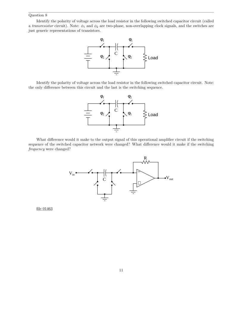
Question 8
Identify the polarity of voltage across the load resistor in the following switched capacitor circuit (calleda transresistor circuit). Note: φ1 and φ2 are two-phase, non-overlapping clock signals, and the switches arejust generic representations of transistors.
CLoad
φ1 φ1
φ2 φ2
Identify the polarity of voltage across the load resistor in the following switched capacitor circuit. Note:the only difference between this circuit and the last is the switching sequence.
CLoad
φ1
φ1φ2
φ2
What difference would it make to the output signal of this operational amplifier circuit if the switchingsequence of the switched capacitor network were changed? What difference would it make if the switchingfrequency were changed?
C
−
+Vout
Vin
R
file 01463
11
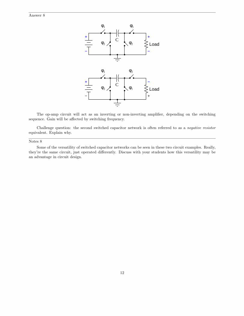
Answer 8
CLoad
φ1
φ1φ2
φ2
CLoad
φ1 φ1
φ2 φ2
The op-amp circuit will act as an inverting or non-inverting amplifier, depending on the switchingsequence. Gain will be affected by switching frequency.
Challenge question: the second switched capacitor network is often referred to as a negative resistor
equivalent. Explain why.
Notes 8
Some of the versatility of switched capacitor networks can be seen in these two circuit examples. Really,they’re the same circuit, just operated differently. Discuss with your students how this versatility may bean advantage in circuit design.
12
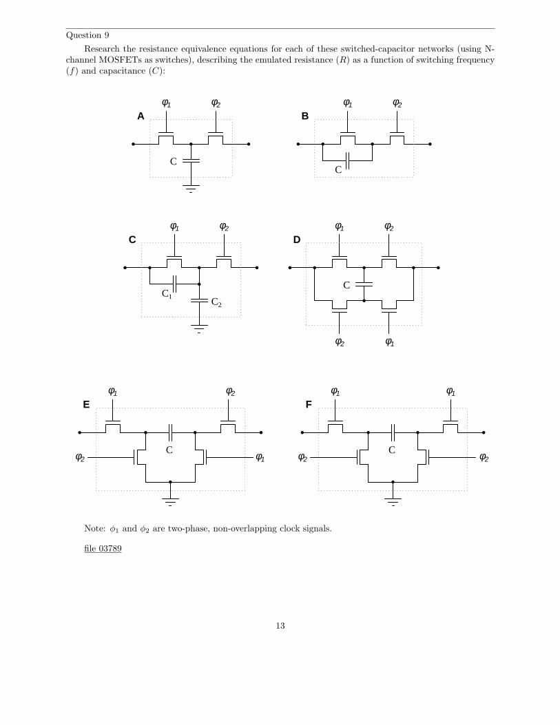
Question 9
Research the resistance equivalence equations for each of these switched-capacitor networks (using N-channel MOSFETs as switches), describing the emulated resistance (R) as a function of switching frequency(f) and capacitance (C):
φ1 φ2 φ1 φ2
φ1 φ2 φ1 φ2
φ1φ2
φ1 φ1
φ2 φ2
φ1
φ2 φ1
φ2
CC
C
C C
C1C2
A B
C D
E F
Note: φ1 and φ2 are two-phase, non-overlapping clock signals.
file 03789
13
Answer 9
Circuit A: Parallel circuit R = 1fC
Circuit B: Series circuit R = 1fC
Circuit C: Series-parallel circuit R = 1f(C1+C2)
Circuit D: Bilinear circuit R = 14fC
Circuit E: Negative transresistor circuit R = −1
fC(the negative sign indicates polarity inversion)
Circuit F: Positive transresistor circuit R = 1fC
Notes 9
The mathematics required to derive these equations directly may be beyond your students’ ability, butthey should still be able to research them! Some of the networks are directly equivalent to one another,making it easier for your students to associate equations: for instance, circuit F is equivalent to circuit B,and circuit E is the same thing as F except for the polarity inversion. It should not take a great deal ofanalysis to realize that circuits A and B must have the same equation as well.
14
Question 10
Given the fact that a switched-capacitor network has the ability to emulate a variable resistance, whatadvantage(s) can you think of for using switched-capacitor networks inside of analog integrated circuits?Identify some practical applications of this technology.
file 03788
Answer 10
Switched-capacitor networks allow us to have electronically variable resistors inside integrated circuits,with no moving parts, which is a technological advantage over standard resistors. Another advantage ofswitched-capacitor circuits is that they typically require less substrate area on an integrated circuit thanan equivalent resistor. A huge advantage is that switched-capacitor networks may be manufactured to givemuch more accurate resistances than plain resistors, which is important in filtering applications.
I’ll let you research (or dream up) some practical applications for this technology.
Notes 10
This question could very well lead to an interesting and lively discussion with your students. Oncestudents recognize the equivalence between switched-capacitor networks and resistors, it is a short cognitiveleap from there to practical applications where variable resistances would be useful (especially in an integratedcircuit environment, where moving parts have traditionally been out of the question).
15
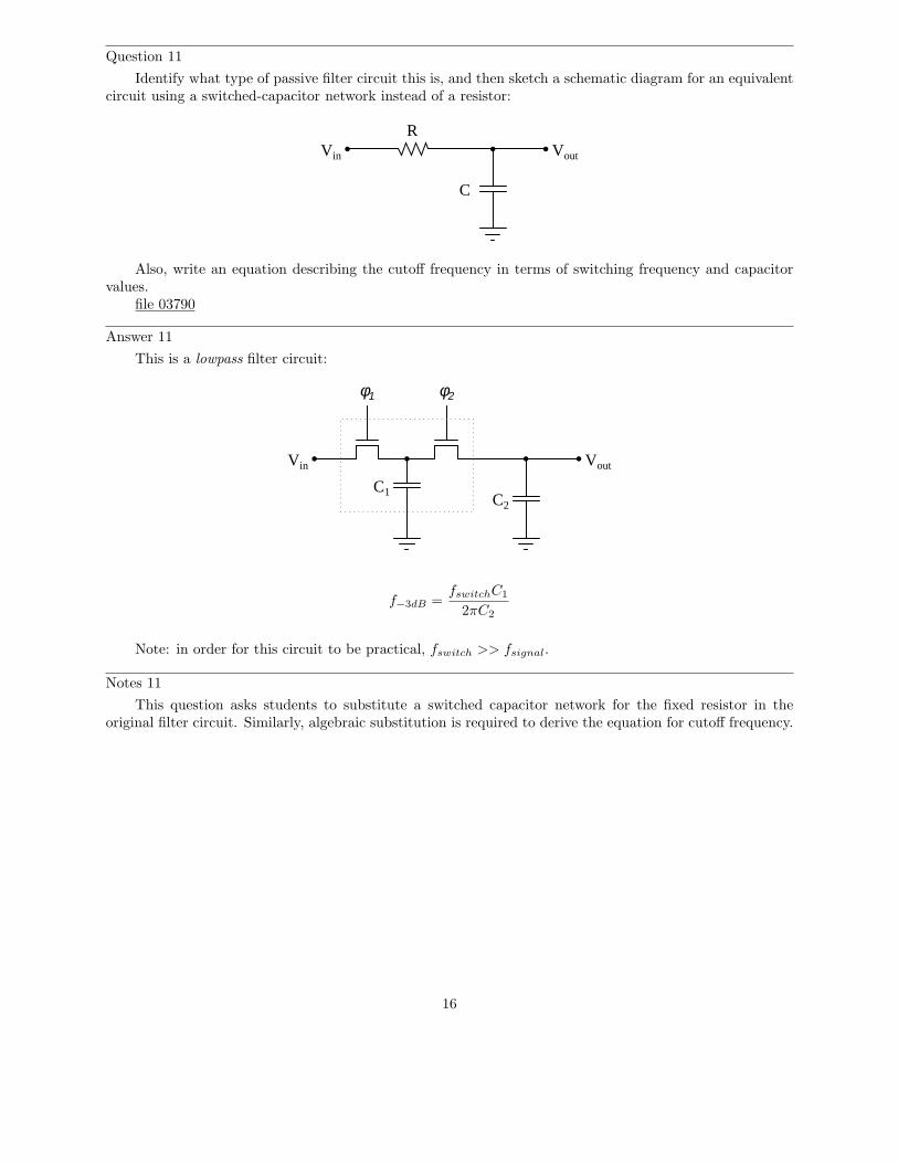
Question 11
Identify what type of passive filter circuit this is, and then sketch a schematic diagram for an equivalentcircuit using a switched-capacitor network instead of a resistor:
VoutVin
R
C
Also, write an equation describing the cutoff frequency in terms of switching frequency and capacitorvalues.
file 03790
Answer 11
This is a lowpass filter circuit:
φ1 φ2
VoutVin
C1C2
f−3dB =
fswitchC1
2πC2
Note: in order for this circuit to be practical, fswitch >> fsignal.
Notes 11
This question asks students to substitute a switched capacitor network for the fixed resistor in theoriginal filter circuit. Similarly, algebraic substitution is required to derive the equation for cutoff frequency.
16
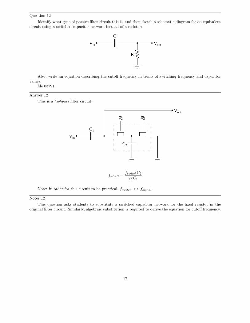
Question 12
Identify what type of passive filter circuit this is, and then sketch a schematic diagram for an equivalentcircuit using a switched-capacitor network instead of a resistor:
VoutVin
R
C
Also, write an equation describing the cutoff frequency in terms of switching frequency and capacitorvalues.
file 03791
Answer 12
This is a highpass filter circuit:
φ1 φ2
Vout
Vin
C2
C1
f−3dB =
fswitchC2
2πC1
Note: in order for this circuit to be practical, fswitch >> fsignal.
Notes 12
This question asks students to substitute a switched capacitor network for the fixed resistor in theoriginal filter circuit. Similarly, algebraic substitution is required to derive the equation for cutoff frequency.
17
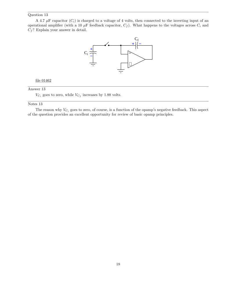
Question 13
A 4.7 µF capacitor (Ci) is charged to a voltage of 4 volts, then connected to the inverting input of anoperational amplifier (with a 10 µF feedback capacitor, Cf ). What happens to the voltages across Ci andCf? Explain your answer in detail.
−
+
Cf
Ci
file 01462
Answer 13
VCigoes to zero, while VCf
increases by 1.88 volts.
Notes 13
The reason why VCigoes to zero, of course, is a function of the opamp’s negative feedback. This aspect
of the question provides an excellent opportunity for review of basic opamp principles.
18
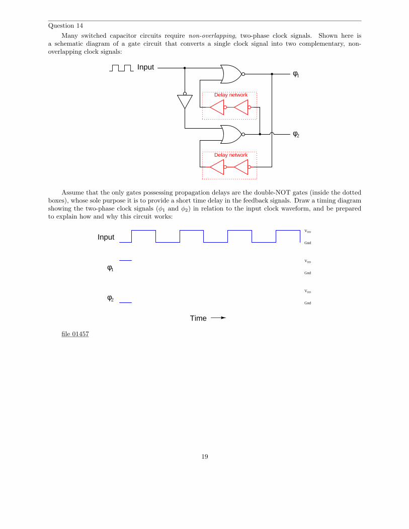
Question 14
Many switched capacitor circuits require non-overlapping, two-phase clock signals. Shown here isa schematic diagram of a gate circuit that converts a single clock signal into two complementary, non-overlapping clock signals:
Delay network
Delay network
φ1
φ2
Input
Assume that the only gates possessing propagation delays are the double-NOT gates (inside the dottedboxes), whose sole purpose it is to provide a short time delay in the feedback signals. Draw a timing diagramshowing the two-phase clock signals (φ1 and φ2) in relation to the input clock waveform, and be preparedto explain how and why this circuit works:
VDD
Gnd
VDD
Gnd
VDD
Gnd
Time
Input
φ1
φ2
file 01457
19
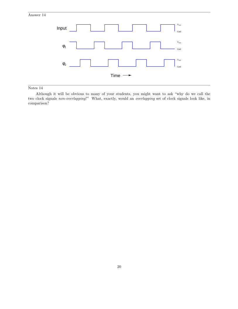
Answer 14
VDD
Gnd
VDD
Gnd
VDD
Gnd
Time
Input
φ1
φ2
Notes 14
Although it will be obvious to many of your students, you might want to ask “why do we call thetwo clock signals non-overlapping?” What, exactly, would an overlapping set of clock signals look like, incomparison?
20
Question 15
The fact that switched capacitor networks can behave equivalently to resistors is exploited in a varietyof integrated circuits. At first, this may seem strange, as switched capacitor networks generally require atleast two switching transistors and a two-phase, non-overlapping clock (in addition to the capacitor itself) inorder to function, which seems like a lot of peripheral circuitry compared to a single resistor. What possibleadvantage is there to using switched capacitor networks in integrated circuits instead of resistors? Supportyour answer with research, if possible.
file 01461
Answer 15
Switched capacitor networks are not just resistor equivalents, they are variable resistor equivalents.Also, these networks actually tend to be smaller than integrated circuit resistors, and are less prone to drift.
There are other advantages to switched capacitor networks, but these are just some of the basic reasonsbehind their prevalence in modern integrated circuits.
Notes 15
Ask your students to explain why switched capacitor networks are less prone to drift than resistorsconstructed on a semiconductor substrate. Just focus on one source of drift, such as temperature, to simplifythe topic. What effect does temperature have on a semiconducting resistor, and why? What effect doestemperature have on a capacitor built of semiconductor layers separated by an insulating layer, and why?With discrete components, are capacitors more stable over time than resistors? Why or why not?
21


![40 MTR 20 WATT QRP LINEAR AMPLIFIER KIT · 1 100 to 220 µf electrolytic capacitor [C1] 1 10 µf electrolytic capacitor [C2] ... 12 volt DC power supply 3 amp rating Proper dummy](https://img.pdfslide.net/doc/110x75/5e740dae5d947e09eb604296/40-mtr-20-watt-qrp-linear-amplifier-1-100-to-220-f-electrolytic-capacitor-c1.jpg)