Embed Size (px)
Citation preview
SX460 AUTOMATIC ,VOLTAGEREGULATOR (AVR)
SPECIFICATION, INSTALLATION AND ADJUSTMENTS
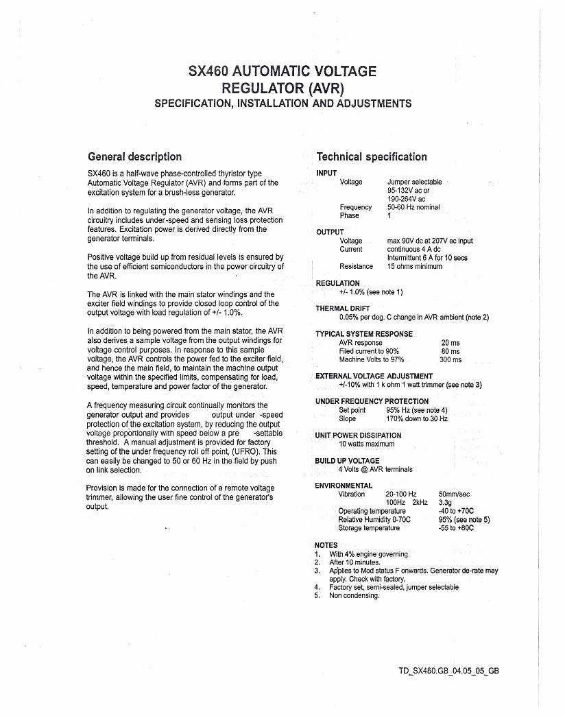
General descriptionSX460 is a half-wave phase-controlled thyristor typeAutomatic Voltage RegUlator (AVR) and forms part of theexcitation system for a brush-less generator.
In addition to regulating the generator voltage, the AVRcircuitry includes under-speed and sensing loss protectionfeatures. Excitation power is derived directly from thegenerator terminals.
Positive voltage build up from residual levels is ensured bythe use of efficient semiconductors in the power circuitry ofthe AVR.
The AVR is linked with the main stator windings and theexciter field windings to provide closed loop control of theoutput voltage with load regulation of +/- 1.0%.
In addition to being powered from the main stator, the AVRalso derives a sample voltage from the output windings forvoltage control purposes. In response to this samplevoltage, the AVR controls the power fed to the exciter field,and hence the main field, to maintain the m-achineoutputvoltage within the specified limits, compensating for load,speed, temperature and power factor of the generator.
A frequency measuring circuit continually monitors thegenerator output and provides output under -speedprotection of the excitation system, by reducing the outputvoltage proportionally with speed below a pre -settablethreshold. A manual adjustment is provided for factorysetting of the under frequency roll off point, (UFRO). Thiscan easily be changed to 50 or 60 Hz in the field by pushon link selection.
Provision is made for the connection of a remote voltagetrimmer, allowing the user fine control of the generator'soutput.
Technical specificationINPUT
Voltage
FrequencyPhase
Jumper selectable95-132V ac or190-264Vac5~0 Hz nominal1
OUTPUTVoltageCurrent
max 90V dc at 20'N ac inputcontinuous 4 A dcIntermittent 6 A for 10 sees15 ohms minimumResistance
REGULATION+/- 1.0% (see note 1)
THERMAL DRIFT0.05% per deg. C change in AVR ambient (note 2)
TYPICAL SYSTEM RESPONSEAVR responseFiled current to 90%Machine Volts to 97%
20 ms80 ms
300 ms
EXTERNAL VOLTAGE ADJUSTMENT+/-10% with 1 k ohm 1 watt trimmer (see note 3)
UNDER FREQUENCY PROTECTIONSet point 95% Hz (see note 4)Slope 170% down to 30 Hz
UNIT POWER DISSIPATION10 watts maximum
BUILD UP VOLTAGE4 Volts @ AVR terminals
ENVIRONMENTALVibration 20-100 Hz
100Hz 2kHzOperating temperatureRelative Humidity 0-70CStorage temperature
50mmlsec3.3g-40 to +7OC95% (see note 5)-55 to +8OC
NOTES1. With 4% engine governing2. After 10 minutes.3. Ap'plies to Mod status F onwards. Generator de-rate may
apply. Check with factory.4. Factory set, semi-sealed, jumper selectable5. Non condensing.
DESIGN DETAIL
VoltageSensing
Low HzDetection
Low PassFilter
SynchronisingCiruit
PotentialDivider &Rectifier
HandTrimmer
StabilityCircuit
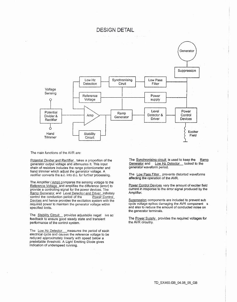
The main functions of the AVR are:
Potential Divider and Rectifier takes a proportion of thegenerator output voltage and attenuates it. This inputchain of resistors includes the range potentiometer andhand trimmer which adjust the generator voltage. Arectifier converts the 'a.c, into d.c. for further processing.
The Amplifier ( Amp) compares the sensing voltage to theReference Voltage and amplifies the difference (error) toprovide a controlling signal for the power devices. TheRamp Generator and Level Detecto r and Driver infinitelycontrol the conduction period of the Power ControlDevices and hence provides the excitation system with therequired power to maintain the generator voltage withinspecified limits.
The Stability Circuit provides adjustable negat ive acfeedback to ensure good steady state and transientperformance of the control system.
The Low Hz Detector measures the period of eachelectrical cycle and causes the reference voltage to bereduced approximately linearly with speed below apresettable threshold. A Light Emitting Diode givesindication of underspeed running.
LevelDetector &
Driver
RampGenerator
PowerControlDevices
ExciterField
The Synchronising circuit is used to keep the RampGenerator and Low Hz Detector locked to thegenerator waveform period.
The Low Pass Filter prevents distorted waveformsaffecting the operation of the AVR.
Power Control Devices vary the amount of exciter fieldcurrent in response to the error signal produced by theAmplifier.
Suppression components are included to prevent subcycle voltage spikes damaging the AVR component sand also to reduce the amount of conducted noise onthe generator terminals.
The Power Supply provides the required voltages forthe AVR circuitry.
FITTING AND OPERATING
UFRq ( under Frequency Roll Off)
D o INDICATOR LED
CC rn FREQUENCYSELECTION
0 D STABILITY 0
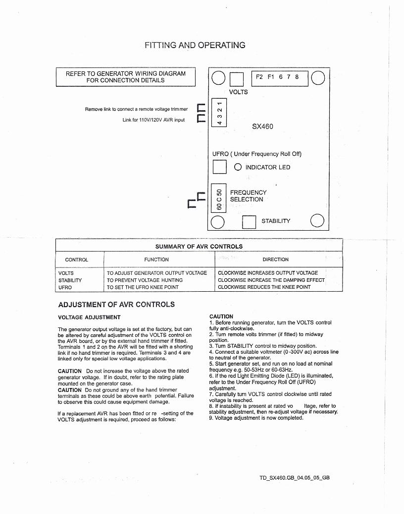
REFER TO GENERATOR WIRING DIAGRAMFOR CONNECTION DETAILS
Remove link to connect a remote voltage trim mer
Link for 110V/120V AVR input
CC
SX460
oD I F2 F1 678 \OiVOLTS
SUMMARY OF AVR CONTRO~S
CONTROL FUNCTION DIRECTION -
VOLTS TO ADJUST GENERATOR OUTPUT VOLTAGE CLOCKWISE INCREASES OUTPUT VOLTAGE
STABILITY TO PREVENT VOLTAGE HUNTING CLOCKWISE INCREASE THE D~PING EFFECT
UFRO TO SET THE UFRO KNEE POINT CLOCKWISE REDUCES THE KNEE POINT
ADJUSTMENT OF AVR CONTROLS
VOLTAGE ADJUSTMENT
The generator output voltage is set at the factory, but canbe altered by careful adjustment of the VOLTS control onthe AVR board, or by the external hand trimmer if fitted.Terminals 1 and 2 of! the AVR will be fitted with a shortinglink if no hand trimmer is required. Terminals 3 and 4 arelinked only for special low voltage applications.
CAUTION Do not increase the voltage above the ratedgenerator voltage. If in doubt, refer to the rating platemounted on the generator case.CAUTION Do not ground any of the hand trimmerterminals as these could be above earth potential. Failureto observe this could cause equipment damage.
If a replacement AVR has been fitted or re -setting of theVOLTS adjustment is required, proceed as follows:
-,1
CAUTION1. Before running generator, turn the VOLTS controlfully anti-clockwise.2. Turn remote volts trimmer (if fitted) to midwayposition.3. Turn STABILITY control to midway position.4. Connect a suitable voltmeter (O-300V ac) across lineto neutral of the generator.5. Start generator set, and run on no load at nominalfrequency e.g. 50-53Hz or 60-63Hz.6. If the red Light Emitting Diode (LED) is illuminated,refer to the Under Frequency Roll Off (UFRO)adjustment.7. Carefully turn VOLTS control clockwise until ratedvoltage is reached.8. If instability is present at rated vo Itage, refer tostability adjustment, then re-adjust voltage if necessary.9. Voltage adjustment is now completed.
FITTING AND OPERATING
STABILITY ADJUSTMENT
The AVR includes a stability or damping circuit toprovide good steady state and transient performance ofthe generator.
The correct setting can be found by running thegenerator at no load and slowly turning the stabilitycontrol anti-clockwise until the generator voltage starts tobecome unstable.
The optimum or critically damped position is slightlyclockwise from this point (l.e. where the machine voltsare stable but close to the unstable re9ion).
UNDER FREQUENCY ROLL OFF (UFRO)ADJUSTMENT
The AVR incorporates an underspeed protection circuitwhich gives a volts/Hz characteristic when the generatorspeed falls below a presettable threshold known as the"knee" point.
The red Light Emitting Diode (LED) gives indication thatthe UFRO circuit is operating.
The UFRO adjustment is preset and sealed and onlyrequires the selection of 50 160Hz usinq the jumper link.
For optimum setting, the LED should illuminate as thefrequency falls just below nominal, i.e. 47Hz on a 50Hzsystem or 57Hz on a 60Hz system.
,.,