Embed Size (px)
Citation preview
http://www.motorola.com/ds6878
SYMBOL DS6878
123SCAN2
DS6878 PosterDS6878 Poster
BLACK
PANTONE 285
Perforation
1
2
3
4
1 2 3 4 5 6
POST
IN W
ORK
ARE
APO
ST IN
WO
RK A
REA
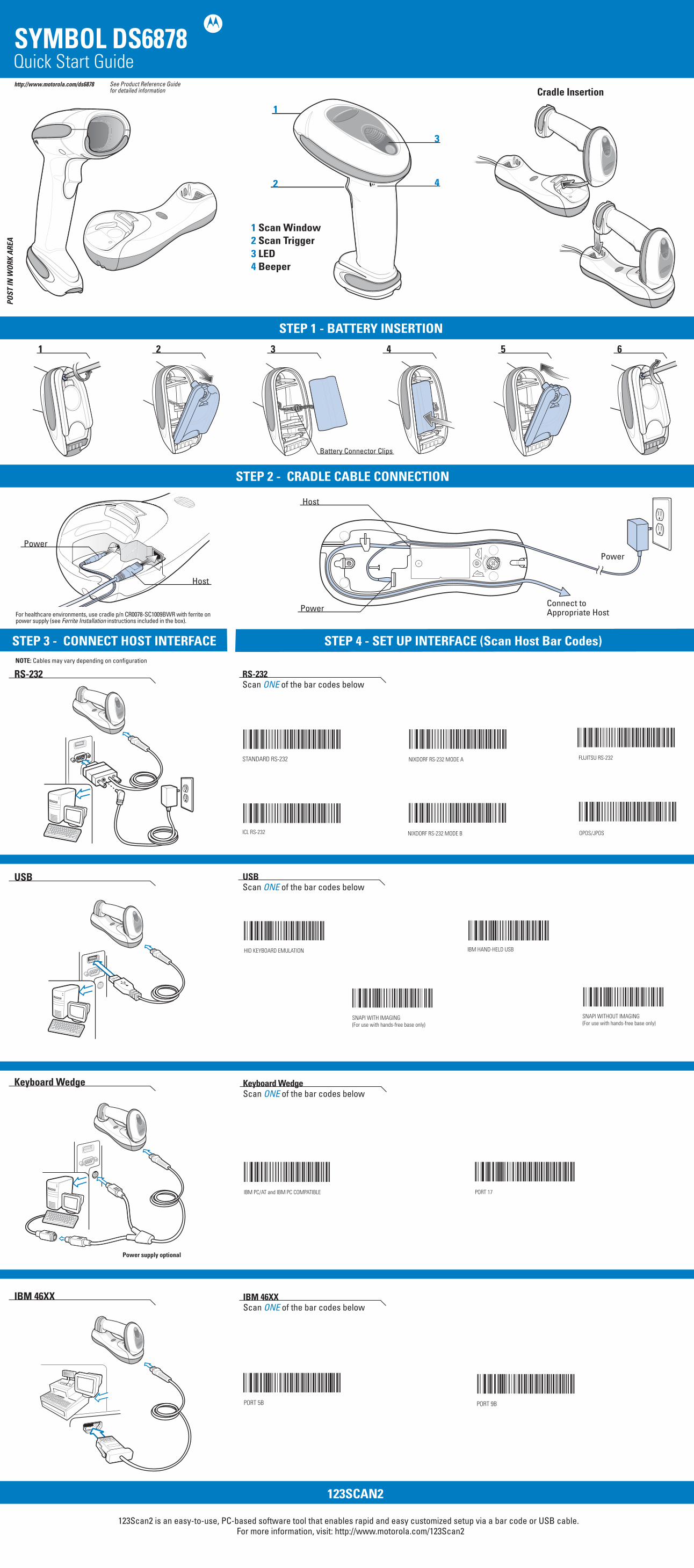
Quick Start Guide
STEP 3 - CONNECT HOST INTERFACE
STEP 2 - CRADLE CABLE CONNECTION
See Product Reference Guide for detailed information
NOTE: Cables may vary depending on configuration
For healthcare environments, use cradle p/n CR0078-SC1009BWR with ferrite on power supply (see Ferrite Installation instructions included in the box).
STEP 4 - SET UP INTERFACE (Scan Host Bar Codes)
Cradle Insertion
STEP 1 - BATTERY INSERTION
1 Scan Window2 Scan Trigger 3 LED 4 Beeper
RS-232
USB
Keyboard Wedge
IBM 46XX
RS-232 Scan ONE of the bar codes below
USB Scan ONE of the bar codes below
Keyboard Wedge Scan ONE of the bar codes below
IBM 46XX Scan ONE of the bar codes below
HID KEYBOARD EMULATION IBM HAND-HELD USB
SNAPI WITH IMAGING(For use with hands-free base only)
SNAPI WITHOUT IMAGING(For use with hands-free base only)
ICL RS-232
NIXDORF RS-232 MODE A
NIXDORF RS-232 MODE B
FUJITSU RS-232
OPOS/JPOS
STANDARD RS-232
PORT 5B PORT 9B
IBM PC/AT and IBM PC COMPATIBLE PORT 17
Battery Connector Clips
Connect to Appropriate HostPower
Host
Host
PowerPower
123Scan2 is an easy-to-use, PC-based software tool that enables rapid and easy customized setup via a bar code or USB cable. For more information, visit: http://www.motorola.com/123Scan2
Power supply optional
DS6878 PosterDS6878 Poster
BLACK
PANTONE 285
http://www.motorola.com/ds6878
PerforationPerforation
SYMBOL DS6878
SYMBOL DS6878
Motorola, Inc. One Motorola Plaza Holtsville, New York 11742-1300, USA
72-132659-01 Revision A March 2010
MOTOROLA and the Stylized M Logo and Symbol and the Symbol logo are registered in the U.S. Patent and Trademark Office. All other product or service names are the property of their respective owners. © Motorola, Inc. 2010
© MOTOROLA, INC. 2010 All rights reserved.Motorola reserves the right to make changes to any product to improve reliability, function, or design.Motorola does not assume any product liability arising out of, or in connection with, the application or use of any product, circuit, or application described herein. No license is granted, either expressly or by implication, estoppel, or otherwise under any patent right or patent, covering or relating to any combination, system, apparatus, machine, material, method, or process in which Motorola products might be used. An implied license exists only for equipment, circuits, and subsystems contained in Motorola products.
This Motorola Product may include Motorola Software, Commercial Third Party Software, and Publicly Available software. Refer to Product Reference Guide for complete copyright, conditions and disclaimer information.
WarrantyFor the complete Motorola hardware product warranty statement, go to:http://www.motorola.com/enterprisemobility/warranty
PatentsThis product is covered by one or more patents. For patent information go to: http://www.motorola.com/enterprisemobility/patents
Service InformationIf you have a problem using the equipment, contact your facility’s Technical or Systems Support. If there is a problem with the equipment, they will contact the Motorola Enterprise Mobility Support at:http://www.motorola.com/enterprisemobility/contactsupportFor the latest version of this guide go to: http://www.motorola.com/enterprisemobility/manuals
SCAN SUFFIX 7 0 0 9
0 1 2 3 4 5 0 1 2 3 4 5
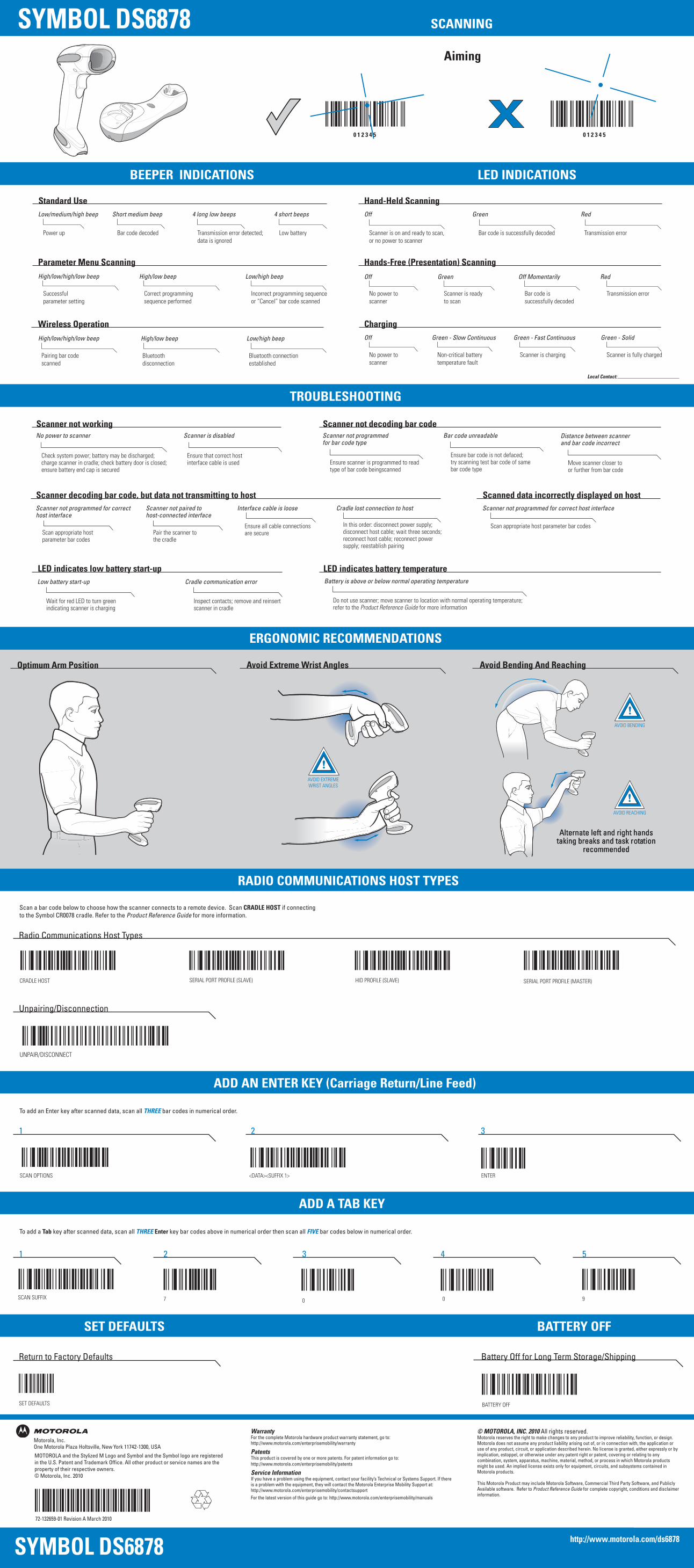
TROUBLESHOOTING
ERGONOMIC RECOMMENDATIONS
Low/medium/high beep
Power up
Short medium beep
Bar code decoded
4 long low beeps
Transmission error detected; data is ignored
4 short beeps
Low battery
Standard Use Hand-Held Scanning
High/low beep
Correct programming sequence performed
Low/high beep
Incorrect programming sequence or “Cancel” bar code scanned
High/low/high/low beep
Successful parameter setting
Parameter Menu Scanning
BEEPER INDICATIONS LED INDICATIONS
Off
Scanner is on and ready to scan, or no power to scanner
Green
Bar code is successfully decoded
Red
Transmission error
Hands-Free (Presentation) Scanning
Off
No power to scanner
Off Momentarily
Bar code is successfully decoded
Green
Scanner is ready to scan
Red
Transmission error
Local Contact:
SCANNING
High/low beep
Bluetoothdisconnection
Low/high beep
Bluetooth connectionestablished
High/low/high/low beep
Pairing bar codescanned
Wireless Operation ChargingOff
No power to scanner
Green - Fast Continuous
Scanner is charging
Green - Slow Continuous
Non-critical batterytemperature fault
Green - Solid
Scanner is fully charged
Aiming
RADIO COMMUNICATIONS HOST TYPES
ADD AN ENTER KEY (Carriage Return/Line Feed)
SET DEFAULTS BATTERY OFF
Battery Off for Long Term Storage/Shipping
BATTERY OFF
Scan a bar code below to choose how the scanner connects to a remote device. Scan CRADLE HOST if connecting to the Symbol CR0078 cradle. Refer to the Product Reference Guide for more information.
To add an Enter key after scanned data, scan all THREE bar codes in numerical order.
CRADLE HOST SERIAL PORT PROFILE (MASTER)SERIAL PORT PROFILE (SLAVE) HID PROFILE (SLAVE)
Radio Communications Host Types
UNPAIR/DISCONNECT
Unpairing/Disconnection
<DATA><SUFFIX 1>SCAN OPTIONS ENTER
1 2 3
SET DEFAULTS
Return to Factory Defaults
No power to scanner
Check system power; battery may be discharged; charge scanner in cradle; check battery door is closed;ensure battery end cap is secured
Scanner is disabled
Ensure that correct host interface cable is used
Scan appropriate host parameter bar codes
Ensure all cable connections are secure
Scanner not workingBar code unreadable
Ensure bar code is not defaced;try scanning test bar code of same bar code type
Distance between scanner and bar code incorrect
Move scanner closer to or further from bar code
Scanner not programmed for bar code type
Ensure scanner is programmed to read type of bar code beingscanned
Scanner not decoding bar code
Scanner not programmed for correct host interface
Interface cable is loose
Scanner decoding bar code, but data not transmitting to hostScanner not programmed for correct host interface
Scan appropriate host parameter bar codes
Scanned data incorrectly displayed on host
Pair the scanner to the cradle
Scanner not paired to host-connected interface
In this order: disconnect power supply;disconnect host cable; wait three seconds; reconnect host cable; reconnect powersupply; reestablish pairing
Cradle lost connection to host
Battery is above or below normal operating temperature
Do not use scanner; move scanner to location with normal operating temperature; refer to the Product Reference Guide for more information
LED indicates battery temperature Low battery start-up
Wait for red LED to turn green indicating scanner is charging
Cradle communication error
Inspect contacts; remove and reinsert scanner in cradle
LED indicates low battery start-up
ADD A TAB KEY
1 2 3 4 5
To add a Tab key after scanned data, scan all THREE Enter key bar codes above in numerical order then scan all FIVE bar codes below in numerical order.
Optimum Arm Position Avoid Extreme Wrist Angles Avoid Bending And Reaching
AVOID REACHING
AVOID BENDING
AVOID EXTREMEWRIST ANGLES
Alternate left and right handstaking breaks and task rotation
recommended
Alternate left and right handstaking breaks and task rotation
recommended