Embed Size (px)
Citation preview

SynReamThe Synthes reaming system
Surgical Technique

3
Contents
Introduction 4
Standard instruments. . . . . . . . . . . . . . . . . . . . . . . . . . . . . . . . . . . . . . . 5
Optional instruments . . . . . . . . . . . . . . . . . . . . . . . . . . . . . . . . . . . . . . . 9
Surgical technique 11
Reduction . . . . . . . . . . . . . . . . . . . . . . . . . . . . . . . . . . . . . . . . . . . . . . 11
Medullary reaming. . . . . . . . . . . . . . . . . . . . . . . . . . . . . . . . . . . . . . . . 13
Set list 16
Bibliography 22
Warning
This description is not sufficient for an immediate application of the
instrumentation.
Instruction by an experienced surgeon in handling this instrumentation is
highly recommended.
SynReam – The Synthes reaming system

4
1 Bhandari M., Guyatt G.H., Tong D., Adili A. & Shaughnessy S.G.: Reamed versus non- reamed intramedullary nailing of lower extremity long bone fractures: a systematic overview and meta-analysis. J. Orthop. Trauma 14, 2-9 (2000).
2 Brumback R.J. & Virkus W.W.: Intramedullary nailing of the femur: reamed versus non- reamed. J. Am. Acad. Orthop. Surg. 8, 83-90 (2000).
3 Hupel T.M., Weinberg J.A., Aksenov S.A. & Schemitsch E.H.: Effect of unreamed, limited reamed, and standard reamed intramedullary nailing on cortical bone porosity and new bone formation. J. Orthop. Trauma 15, 18-27 (2001).
4 Chapman M.W.: The effect of reamed and non-reamed intramedullary nailing on fracture healing. Clin. Orthop. S230-S238 (1998).
5 Müller C.A., Schavan R., Frigg R., Perren S.M.: Intramedullary pressure increase for different commercial and experimental reaming systems: An experimental investigation. J. of Orthop. Trauma; 12: (540–546)
6 Müller C. A., Baumgart F., Wahl D., Perren S. M., Pfister U.: Technical innovations in medullary reaming: Reamer design and intramedullary pressure increase. J. of Trauma, 49, 3, 440–445.
7 Müller C. A., Frigg R., Pfister U.: Can modifications to reamer and flexible shaft design decrease intramedullary pressure during reaming? An experimental investigation. Techniques in Orthopaedics, 11, 1, 18–27.
8 Müller C. A., Frigg R., Pfister U.: Effect of flexible drive diameter and reamer design on the increase of pressure in the medullary cavity during reaming. Injury, 24, Suppl. 3: 40–47)
9 Stuermer K.M., Schuchardt W.: Neue Aspekte der gedeckten Marknagelung und des Aufbohrens der Markhöhle im Tierexperiment. II.: Der intramedulläre Druck beim Aufbohren der Markhöhle. Unfallheilkunde, 83, 1980.
10 Wenda K., Ritter G., Degreif J., Rudigier J.: Zur Genese pulmonaler Komplikationen nach Marknagelosteosynthesen. Unfallchiurg, 91, 1988, 432–435
11 Wenda K., Henrichs K.J., Biegler J., Erbel R.: Nachweis von Markembolien während Oberschenkelmarknagelungen mittels transoesophagealer Echokardiographie. Unfallchirurg, 15, 2, 1989, 73–76.
12 Shabalovskaya S.A.: On the nature of the biocompatibility and medical applications of NiTi shape memory and superelastic alloys. Bio-Medical Materials and Engineering, 6, 4, 1996, 267-289.
13 Ryhäuen J., et al: Biocompatibility of nickel-titanium shape memory metal and its corrosion behavior in human cell cultures. J Biomed Mater Res, 35, 4, 1997.
SynReam
Introduction
There are various intramedullary nailing indications where reaming of the
medullary cavity is required. In these indications, reaming and the use of
the appropriate nail can achieve high stability for an early functional reha-
bilitation, which is the most important aim of internal fixation 1–4.
In their study, Müller et al. 5 have proved that the reaming process causes
significant important intramedullary pressure increases. An important aim
in the development of SynReam was therefore the reduction of pressure
during reaming. The diameter of the shaft and the geometry of the rea-
mer heads have considerable influence on the pressure in the medullary
canal 6–11. The geometry of the SynReam reamer heads has been designed
according to the most recent research findings and the use of super-
elastic NITINOL has reduced the shaft diameter considerably. This ensures
an optimal clearance of chips and an important pressure and temperature
reduction compared to conventional reaming systems.
SynReam – The Synthes reaming system

5
14 Müller C.A., Mc Iff T., Rahn B.A., Pfister U., Weller S.: Intramedullary pressure, strain on the diaphysis and increase in cortical temperature when reaming the femoral medullary cavity – A comparison of blunt and sharp reamers. Injury 24, Suppl. 3: 22 – 30
15 Müller C.A., Rahn B.A., Pfister U., Weller S.: Extent of bluntness and damage to reamers from hospitals. Injury 24, Suppl. 3, 31 – 35
Standard instruments
Flexible Shaft (352.040)
The NITINOL shaft allows driving all reamer-head sizes with one shaft
diameter only. Due to the closed cross section, the shaft can be used
both clockwise and counter-clockwise, and is easy to clean. The front
coupling has a hexagon for torsional transmission. In addition, the shaft is
equipped with a click-on mechanism that primarily fixes the reamer heads
onto the flexible shaft.
Pass the reaming rod through the shaft and reamer or reduction head to
ensure a secure, positive connection between both parts. The insertion of
the reaming rod connects both parts firmly to one another.
Caution: Never ream without using a reaming rod, as it secures the con-
nection between the reamer head and the flexible shaft.
The coupling of the machine corresponds to that of the standard system
(large Synthes quick coupling) and allows coupling with the attachment
for medullary reaming as well as with the angular drive.
Use the individual reamer heads to ream in 0.5mm increments.
Reamer Heads (352.085–352.170)
The chip spaces ensure an optimal chip flow. The 8.5mm reamer head is
equipped with front-cutting edges. For this reason, this diameter should
be selected as the starting diameter. Reamer heads are available in diam-
eters of 8.5 to 17mm (in 0.5mm increments).
Note: Inspect the reamer heads for damages, as blunt reamer heads can
increase intramedullary pressure and temperature significantly14 – 15.
For technical reasons (cutting geometry), the reamer heads cannot
be resharpened. Damaged reamer heads have to be replaced.
SynReam – The Synthes reaming system
6
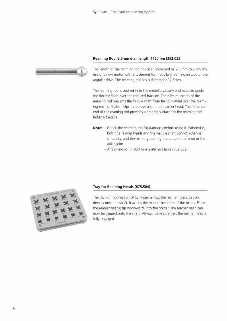
Reaming Rod, 2.5mm dia., length 1150mm (352.033)
The length of the reaming rod has been increased by 200mm to allow the
use of a new motor with attachment for medullary reaming instead of the
angular drive. The reaming rod has a diameter of 2.5mm.
The reaming rod is pushed in to the medullary cavity and helps to guide
the flexible shaft over the reduced fracture. The olive at the tip of the
reaming rod prevents the flexible shaft from being pushed over the ream-
ing-rod tip. It also helps to remove a jammed reamer head. The flattened
end of the reaming rod provides a holding surface for the reaming rod
holding forceps.
Note: – Check the reaming rod for damages before using it. Otherwise,
both the reamer heads and the flexible shaft cannot advance
smoothly, and the reaming rod might end up in the knee or the
ankle joint.
– A reaming rof of 950 mm is also available (352.032).
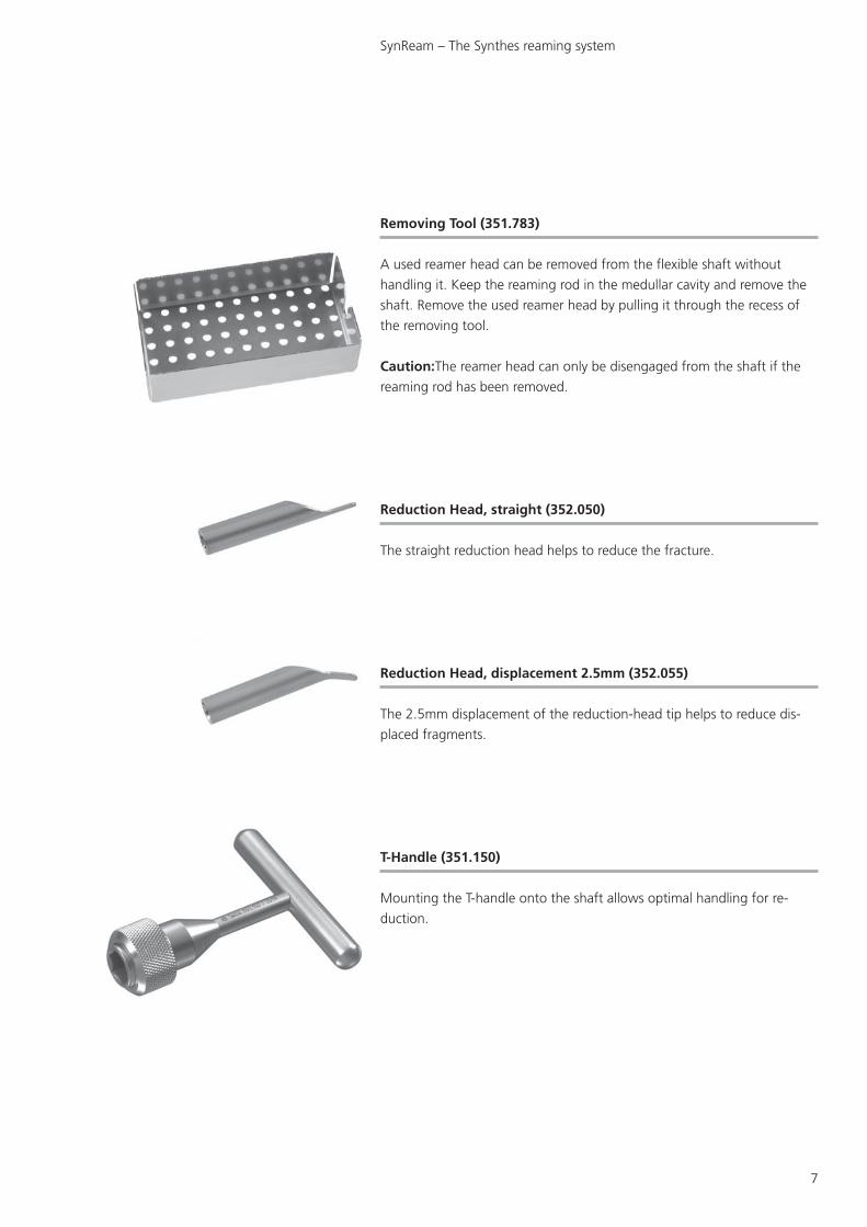
Tray for Reaming Heads (675.504)
The click-on connection of SynReam allows the reamer heads to click
directly onto the shaft. It avoids the manual insertion of the heads. Place
the reamer heads; tip downward, into the holder. The reamer head can
now be clipped onto the shaft. Always make sure that the reamer head is
fully engaged.
SynReam – The Synthes reaming system
7
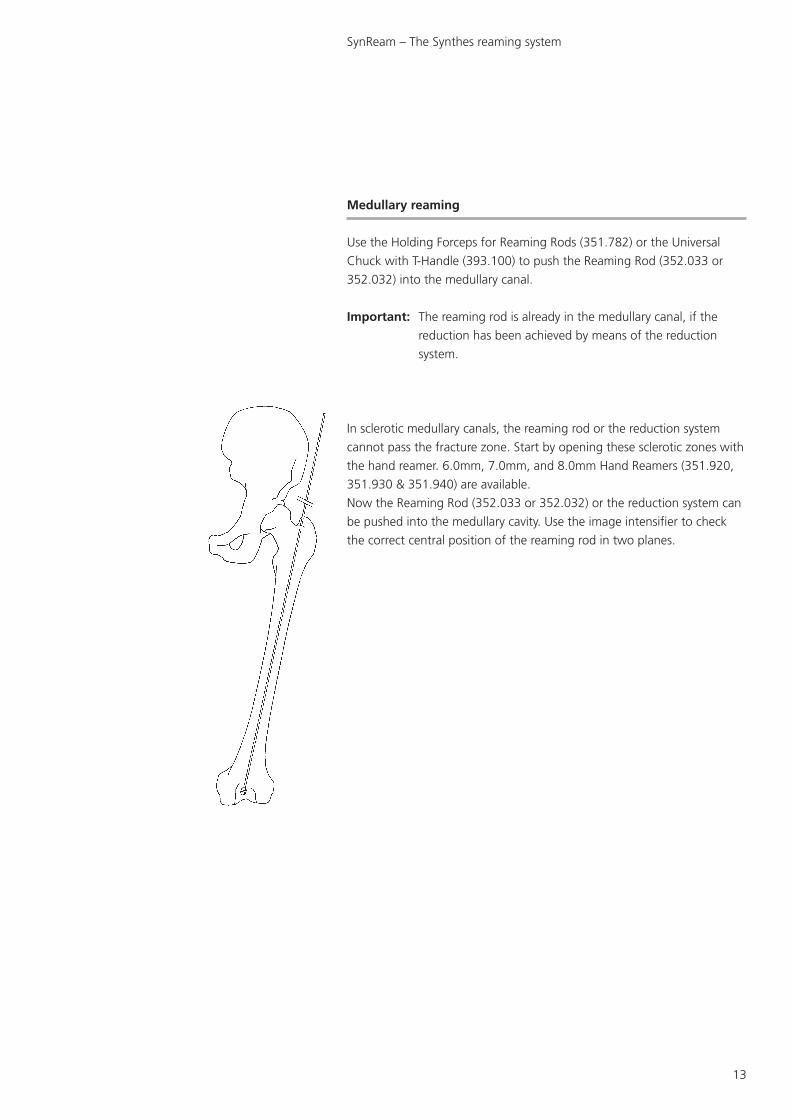
Removing Tool (351.783)
A used reamer head can be removed from the flexible shaft without
handling it. Keep the reaming rod in the medullar cavity and remove the
shaft. Remove the used reamer head by pulling it through the recess of
the removing tool.
Caution:The reamer head can only be disengaged from the shaft if the
reaming rod has been removed.
Reduction Head, straight (352.050)
The straight reduction head helps to reduce the fracture.
Reduction Head, displacement 2.5mm (352.055)
The 2.5mm displacement of the reduction-head tip helps to reduce dis-
placed fragments.
T-Handle (351.150)
Mounting the T-handle onto the shaft allows optimal handling for re-
duction.
SynReam – The Synthes reaming system

8
Holding Forceps for Reaming Rods (351.782)
The holding forceps for reaming rods combines three instruments of the
current reaming system. It combines the function of the following prod-
ucts:
Vice Grip (391.880)
Universal Chuck with T-Handle (393.100)
Holding Forceps (351.780)
Handling
1. Insertion
Insert the reaming rod into the medullary cavity using the holding forceps
for reaming rods coupled parallel to the reaming rod.
2. Holding
For reaming, use the holding forceps to hold the end of the reaming
rod parallel or lengthwise. This prevents the withdrawal of the reaming
rod when pulling the flexible shaft out of the medullary canal. Once the
reamer head has been removed from the bone, the reaming rod can be
grasped between the reamer head and the canal entry point.
3. Emergency application
Should a reamer head get jammed, use the holding forceps for reaming
rods to take hold of the back end of the reaming rod, and remove the
jammed reamer with light hammer blows on the holding forceps.
SynReam – The Synthes reaming system

9
Optional instruments
Universal Chuck with T-Handle (393.100)
This handle is used to push the centering pin and the reaming rod into
the medullary canal.
Hand Reamers, 6, 7, and 8mm dia. (351.920, 351.930 & 351.940)
These reamers are used when the medullary canal is too small to accomo-
date the 8.5mm starting reamer.
Tissue Protector (351.050)
The tissue protector is used to protect the soft tissues when reaming.
Hold the tissue protector at the insertion point between soft tissue and
flexible shaft.
Reamer Heads (352.175 – 352.190)
The chip spaces ensure an optimal chip flow. The 8.5mm reamer head is
equipped with front-cutting edges. For this reason, this should be the first
reamer used.
In addition to standard reamer heads (see page 5), there are also 17.5 to
19mm reamer heads (in 0.5mm increments) available.
SynReam – The Synthes reaming system

10
Air Jet to clean instruments (351.800)
The air jet is made of synthetic material that cannot be sterilized. It is used
together with the air tube to clean the inside of the flexible shaft. It can
be coupled to the compressed-air supply using an air hose with quick
coupling.
Air Tube, 2.0mm dia. (351.810) for use with the air jet
To connect the tube to the air jet, remove the head of the air jet, push the
tube through the head, and screw the head back onto the jet.
Cleaning Brush (352.041)
Use this cleaning brush to clean the cannulation of the flexible shaft. In
case of an obstructed cannulation, use the reaming rod to push through
it.
The cleaning brush cannot be autoclaved.
SynReam – The Synthes reaming system

11
351.150
352.050
352.040
352.055
Surgical technique
The reduction aid can be used after opening of the medullary canal (see
surgical technique of the corresponding implant system).
Reduction
Mount one of the Reduction Heads (352.050 or 352.055) and the T-
Handle (351.150) onto the Flexible Shaft (352.040). For the fixation of the
reduction head, insert the Reaming Rod (352.033 or 352.032) until the
olive touches the reduction head. During reduction, the reaming rod must
be held in situ to ensure that it does not miss the displaced fragment.
Important: A secure fixation of the reduction head is not guaranteed if
the reduction system is used without the reaming rod. The
reduction head may be lost in the medullary canal.
SynReam – The Synthes reaming system

12
Insert the reduction system into the medullary cavity, and reduce the frag-
ments using image-intensifier control.
After reduction, remove the reduction system, and leave the reaming rod
in the medullary cavity.
Note: As each manipulation in the fat-filled medullary cavity causes an
intramedullary pressure increase, reduction with the reduction
system also increases the pressure. Manipulations should therefore
be minimized. As an alternative, reduction can also be carried out
using the reaming rod only.
SynReam – The Synthes reaming system
13
Medullary reaming
Use the Holding Forceps for Reaming Rods (351.782) or the Universal
Chuck with T-Handle (393.100) to push the Reaming Rod (352.033 or
352.032) into the medullary canal.
Important: The reaming rod is already in the medullary canal, if the
reduction has been achieved by means of the reduction
system.
In sclerotic medullary canals, the reaming rod or the reduction system
cannot pass the fracture zone. Start by opening these sclerotic zones with
the hand reamer. 6.0mm, 7.0mm, and 8.0mm Hand Reamers (351.920,
351.930 & 351.940) are available.
Now the Reaming Rod (352.033 or 352.032) or the reduction system can
be pushed into the medullary cavity. Use the image intensifier to check
the correct central position of the reaming rod in two planes.
SynReam – The Synthes reaming system

14
For the initial reaming, the flexible Shaft (352.040) is usually equipped
with the 8.5mm Reamer Head (352.085). Clip the shaft onto the reamer
head in the Tray for Reaming Heads (675.504). If the click-on connection
does not fit, turn the shaft slightly until the hexagon matches.
Important: This is only a primary connection. Always ream over the
reaming rod to ensure a secure connection.
Use the Compact Air Drive II (511.701) or the Power Drive (530.100) with
the Attachment for Medullary Reaming (511.785) as the driving unit.
Guide the reaming system over the reaming rod.
Do not rotate the reamer head when inserting it into the medullary canal.
The Tissue Protector (351.050) protects the soft tissues. Use the highest
speed and slight but uniform force to advance the reamer head in the
medullary canal. Move the reaming shaft backwards and forwards to
remove the bone chips from the reamer head. This prevents jamming of
the reamer head in the medullary cavity.
After full-length reaming of the medullary cavity, withdraw the reaming
shaft until the entire reamer head is visible. To prevent a loss of reduction,
the assistant should grasp the reaming rod at the canal entry point,
and hold the rod in place using the Holding Forceps for Reaming Rods
(351.782).
If a reamer head gets jammed while reaming, disconnect the Attachment
for Medullary Reaming (511.785). Mount the holding forceps onto the
reaming rod (in the countersinking). Light hammer blows on the holding
forceps allow drawing the jammed reamer head from the medullary canal
using the reaming rod. As an alternative, release the reamer head by turn-
ing the shaft backwards.
SynReam – The Synthes reaming system
15
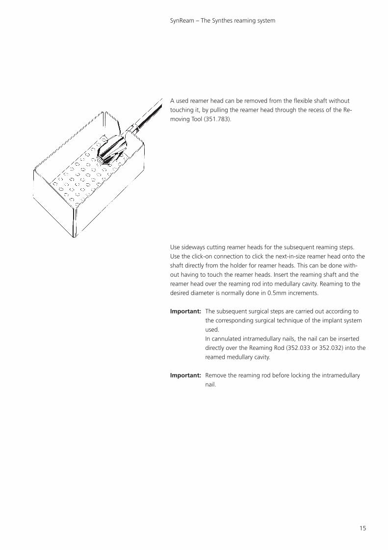
A used reamer head can be removed from the flexible shaft without
touching it, by pulling the reamer head through the recess of the Re-
moving Tool (351.783).
Use sideways cutting reamer heads for the subsequent reaming steps.
Use the click-on connection to click the next-in-size reamer head onto the
shaft directly from the holder for reamer heads. This can be done with-
out having to touch the reamer heads. Insert the reaming shaft and the
reamer head over the reaming rod into medullary cavity. Reaming to the
desired diameter is normally done in 0.5mm increments.
Important: The subsequent surgical steps are carried out according to
the corresponding surgical technique of the implant system
used.
In cannulated intramedullary nails, the nail can be inserted
directly over the Reaming Rod (352.033 or 352.032) into the
reamed medullary cavity.
Important: Remove the reaming rod before locking the intramedullary
nail.
SynReam – The Synthes reaming system

16
Set list
SYNCASE without contents
675.500 SYNCASE for SynReam Instrument Set
consisting of:
675.501 Tray, bottom, for SynReam Instruments
675.502 Tray, top, for SynReam Instruments
675.503 Lid for no. 675.500
675.504 Tray for Reaming Heads
SYNCASE with contents
175.500 SynReam Instrument Set in SYNCASE
consisting of:
675.501 Tray, bottom, for SynReam Instruments
675.502 Tray, top, for SynReam Instruments
675.503 Lid for no. 675.500
675.504 Tray for Reaming Heads
351.150 T-Handle with quick coupling, L 85mm
351.782 Holding Forceps for 2.5mm Reaming Rods
351.783 Removing Tool
SynReam – The Synthes reaming system
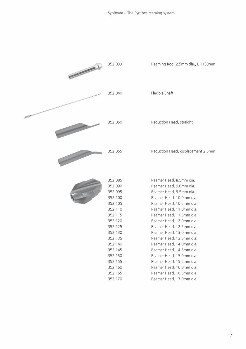
17
352.033 Reaming Rod, 2.5mm dia., L 1150mm
352.040 Flexible Shaft
352.050 Reduction Head, straight
352.055 Reduction Head, displacement 2.5mm
352.085 Reamer Head, 8.5mm dia.
352.090 Reamer Head, 9.0mm dia.
352.095 Reamer Head, 9.5mm dia.
352.100 Reamer Head, 10.0mm dia.
352.105 Reamer Head, 10.5mm dia.
352.110 Reamer Head, 11.0mm dia.
352.115 Reamer Head, 11.5mm dia.
352.120 Reamer Head, 12.0mm dia.
352.125 Reamer Head, 12.5mm dia.
352.130 Reamer Head, 13.0mm dia.
352.135 Reamer Head, 13.5mm dia.
352.140 Reamer Head, 14.0mm dia.
352.145 Reamer Head, 14.5mm dia.
352.150 Reamer Head, 15.0mm dia.
352.155 Reamer Head, 15.5mm dia.
352.160 Reamer Head, 16.0mm dia.
352.165 Reamer Head, 16.5mm dia.
352.170 Reamer Head, 17.0mm dia.
SynReam – The Synthes reaming system
18
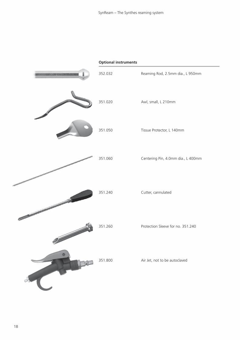
Optional instruments
352.032 Reaming Rod, 2.5mm dia., L 950mm
351.020 Awl, small, L 210mm
351.050 Tissue Protector, L 140mm
351.060 Centering Pin, 4.0mm dia., L 400mm
351.240 Cutter, cannulated
351.260 Protection Sleeve for no. 351.240
351.800 Air Jet, not to be autoclaved
SynReam – The Synthes reaming system

19
351.810 Air Tube, 2.0mm dia.
351.920 Hand Reamer, 6.0mm dia.
351.930 Hand Reamer, 7.0mm dia.
351.940 Hand Reamer, 8.0mm dia.
352.041 Cleaning Brush for Flexible Shaft
352.175 Reamer Head, 17.5mm dia.
352.180 Reamer Head, 18.0mm dia.
352.185 Reamer Head, 18.5mm dia.
352.190 Reamer Head, 19.0mm dia.
393.100 Universal Chuck with T-Handle
SynReam – The Synthes reaming system

20
Bibliography
Bhandari M., Guyatt G.H., Tong D., Adili A. & Shaughnessy S.G., Reamed versusnon-reamed intramedullary nailing of lower extremity long bone fractures: a systematicoverview and meta-analysis. J. Orthop. Trauma 14, 2 – 9 (2000).
Brumback R.J. & Virkus W.W., Intramedullary nailing of the femur: reamed versusnon-reamed. J. Am. Acad. Orthop. Surg. 8, 83 – 90 (2000).
Chapman M.W., The effect of reamed and non-reamed intramedullary nailing on fracturehealing. Clin. Orthop. S230 – S238 (1998).
Hupel T.M., Weinberg J.A., Aksenov S.A. & Schemitsch E.H., Effect of unreamed,limited reamed, and standard reamed intramedullary nailing on cortical bone porosityand new bone formation. J. Orthop. Trauma 15, 18 – 27 (2001).
Müller C.A., Schavan R., Frigg R., Perren S.M.:Intramedullary pressure increase for different commercial and experimental reaming systems: An experimental investigation J. of Orthop. Trauma 12, 540 – 546
Müller C. A., Baumgart F., Wahl D., Perren S. M., Pfister U.:Technical innovations in medullary reaming: Reamer design and intramedullary pressure increase.J. of Trauma, 49, 3, 440 – 445
Müller C. A., Frigg R., Pfister U.:Can modifications to reamer and flexible shaft design decrease intramedullary pressure during reaming? An experimental investigation.Techniques in Orthopaedics, 11, 1, 18–27
Müller C. A., Frigg R., Pfister U.:Effect of flexible drive diameter and reamer design on the increase of pressure in the medullary cavity during reaming.Injury, 24, Suppl. 3: 40 – 47
Müller C.A., Mc Iff T., Rahn B.A., Pfister U., Weller S.:Intramedullary pressure, strain on the diaphysis and increase in cortical temperature when reaming the femoral medullary cavity – A comparison of blunt and sharp reamers.Injury 24, Suppl. 3: 22 – 30
Müller C.A., Rahn B.A., Pfister U., Weller S.:Extent of bluntness and damage to reamers from hospitals.Injury 24, Suppl. 3, 31 – 35
Pape N.C., Dwenger A., Grotz M., Kaever V., Negatsch R., Kleemann W., Regel G., Strum J.A., Tscherne H.:Does the reamer type influence the degree of lung dysfunction after femoral nailing following severe trauma? An animal study.J Orthop Trauma. 1994; 8; 4:300–309
Ryhäuen J., et al, Biocompatibility of nickel-titanium shape memory metal and itscorrosion behavior in human cell cultures. J Biomed Mater Res, 35, 4, 1997.
Shabalovskaya S.A., On the nature of the biocompatibility and medical applications ofNiTi shape memory and superelastic alloys. Bio-Medical Materials and Engineering, 6, 4,1996, 267 – 289.
Stuermer K.M., Schuchardt W.:Neue Aspekte der gedeckten Marknagelung und des Aufbohrens der Markhöhle im Tierexperiment. II.: Der intramedulläre Druck beim Aufbohren der Markhöhle.Unfallheilkunde, 83, 1980.
Wenda K., Ritter G., Degreif J., Rudigier J.:Zur Genese pulmonaler Komplikationen nach Marknagelosteosynthesen.Unfallchiurg, 91, 1988, 432 – 435
Wenda K., Henrichs K.J., Biegler J., Erbel R.:Nachweis von Markembolien während Oberschenkelmarknagelungen mittels transoesophagealer Echokardiographie.Unfallchirurg, 15, 2, 1989, 73 – 76.
SynReam – The Synthes reaming system

21
SynReam – The Synthes reaming system
Notes

0123Presented by: 036.
000.
808
SE_0
1870
5 ©
Str
atec
Med
ical
20
05
Prin
ted
in S
witz
erla
nd
LA
G
Subj
ect
to m
odifi
catio
ns.