Embed Size (px)
Citation preview
RTL Hardware Design Chapter 6 1
Synthesis Of VHDL Code
RTL Hardware Design Chapter 6 2
Outline
1. Fundamental limitation of EDA software2. Realization of VHDL operator3. Realization of VHDL data type4. VHDL synthesis flow5. Timing consideration
RTL Hardware Design Chapter 6 3
1. Fundamental limitation of EDA software
• Can “C-to-hardware” be done?• EDA tools:
– Core: optimization algorithms– Shell: wrapping
• What does theoretical computer science say?– Computability – Computation complexity
RTL Hardware Design Chapter 6 4
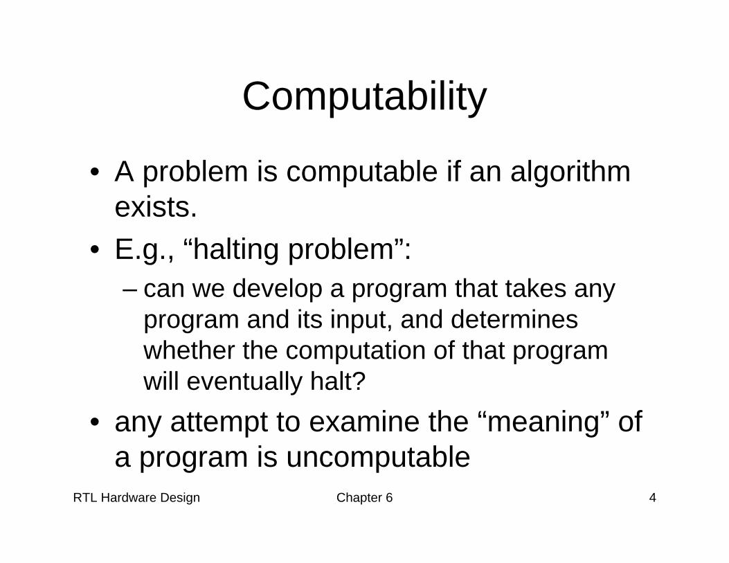
Computability
• A problem is computable if an algorithm exists.
• E.g., “halting problem”:– can we develop a program that takes any
program and its input, and determines whether the computation of that program will eventually halt?
• any attempt to examine the “meaning” of a program is uncomputable
RTL Hardware Design Chapter 6 5
Computation complexity
• How fast an algorithm can run (or how good an algorithm is)?
• “Interferences” in measuring execution time: – types of CPU, speed of CPU, compiler etc.

RTL Hardware Design Chapter 6 6
Big-O notation• f(n) is O(g(n)):
if n0 and c can be found to satisfy:f(n) < cg(n) for any n, n > n0
• g(n) is simple function: 1, n, log2n, n2, n3, 2n
• Following are O(n2):
RTL Hardware Design Chapter 6 7
Interpretation of Big-O
• Filter out the “interference”: constants and less important terms
• n is the input size of an algorithm• The “scaling factor” of an algorithm:
What happens if the input size increases
RTL Hardware Design Chapter 6 8
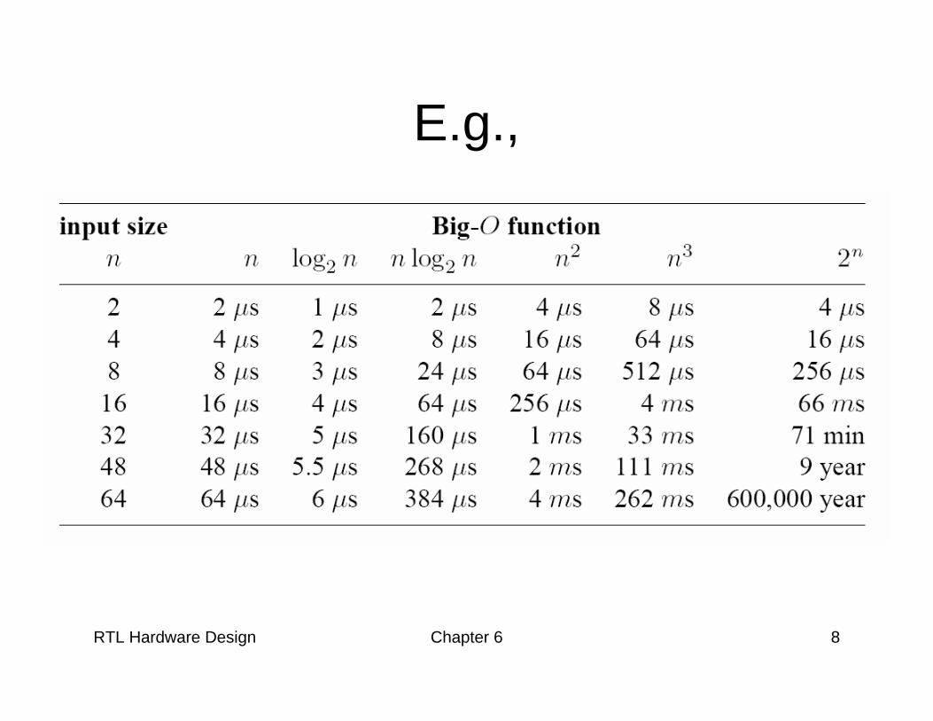
E.g.,
RTL Hardware Design Chapter 6 9
• Intractable problems: – algorithms with O(2n)– Not realistic for a larger n– Frequently tractable algorithms for sub-
optimal solution exist• Many problems encountered in synthesis
are intractable
RTL Hardware Design Chapter 6 10
Theoretical limitation
• Synthesis software does not know your intention
• Synthesis software cannot obtain the optimal solution
• Synthesis should be treated as transformation and a “local search” in the “design space”
• Good VHDL code provides a good starting point for the local search
RTL Hardware Design Chapter 6 11
• What is the fuss about:– “hardware-software” co-design?– SystemC, HardwareC, SpecC etc.?
RTL Hardware Design Chapter 6 12
2. Realization of VHDL operator• Logic operator
– Simple, direct mapping• Relational operator
– =, /= fast, simple implementation exists– >, < etc: more complex implementation,
larger delay • Addition operator• Other arith operators: support varies
RTL Hardware Design Chapter 6 13
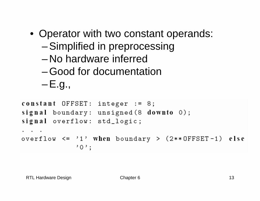
• Operator with two constant operands:– Simplified in preprocessing– No hardware inferred– Good for documentation – E.g.,
RTL Hardware Design Chapter 6 14
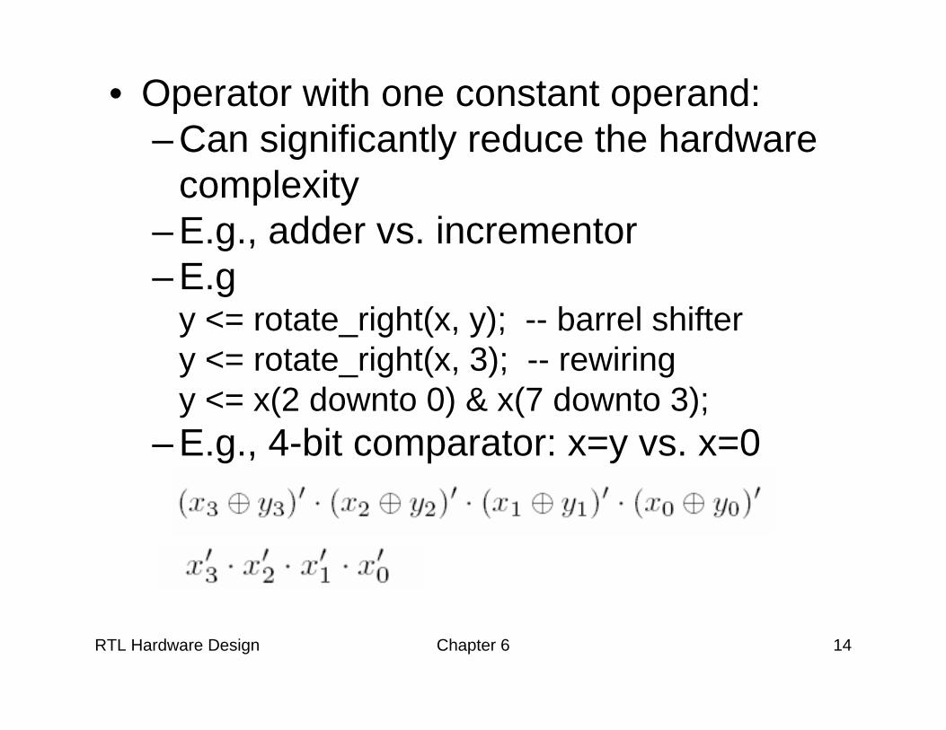
• Operator with one constant operand:– Can significantly reduce the hardware
complexity– E.g., adder vs. incrementor– E.g
y <= rotate_right(x, y); -- barrel shiftery <= rotate_right(x, 3); -- rewiringy <= x(2 downto 0) & x(7 downto 3);
– E.g., 4-bit comparator: x=y vs. x=0
RTL Hardware Design Chapter 6 15
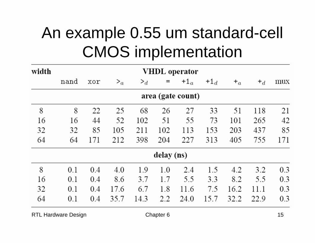
An example 0.55 um standard-cell CMOS implementation
RTL Hardware Design Chapter 6 16
3. Realization of VHDL data type
• Use and synthesis of ‘Z’• Use of ‘-’

RTL Hardware Design Chapter 6 17
Use and synthesis of ‘Z’• Tri-state buffer:
– Output with “high-impedance”– Not a value in Boolean algebra – Need special output circuitry (tri-state buffer)
RTL Hardware Design Chapter 6 18
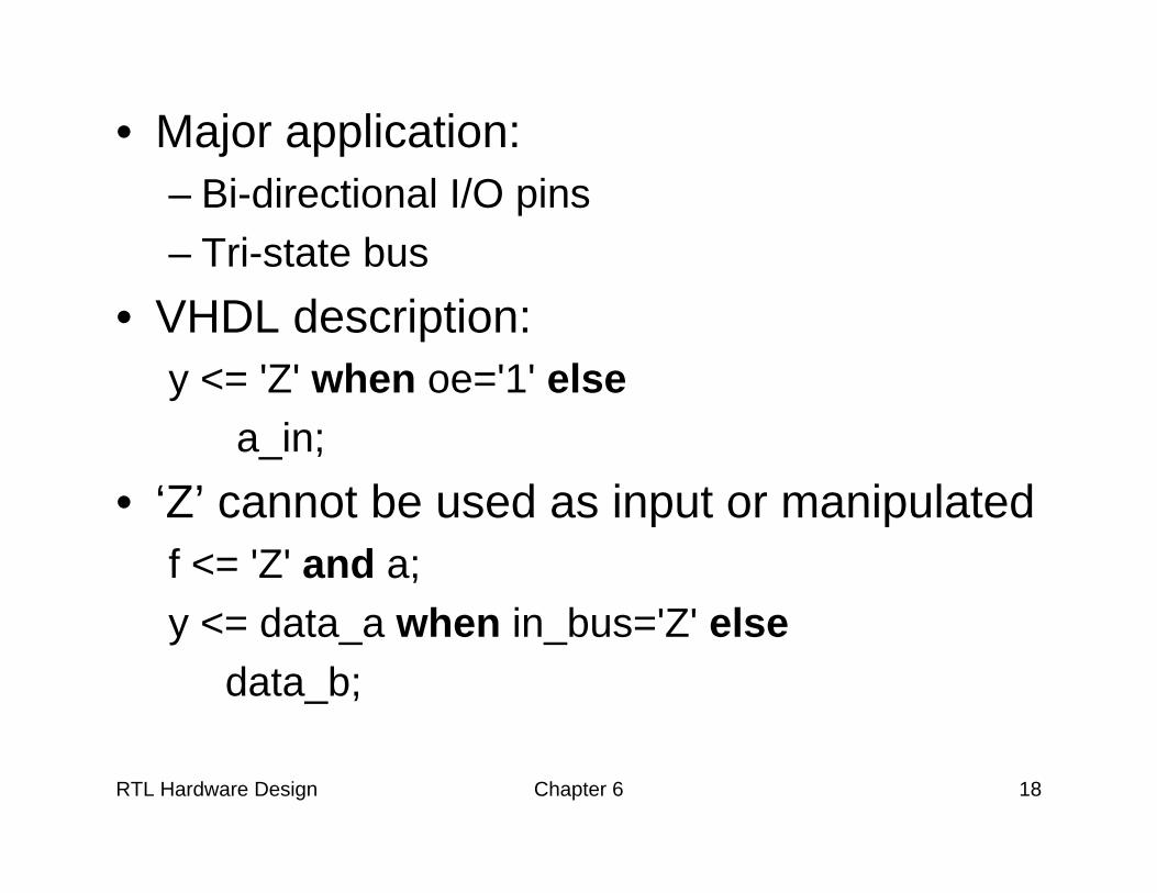
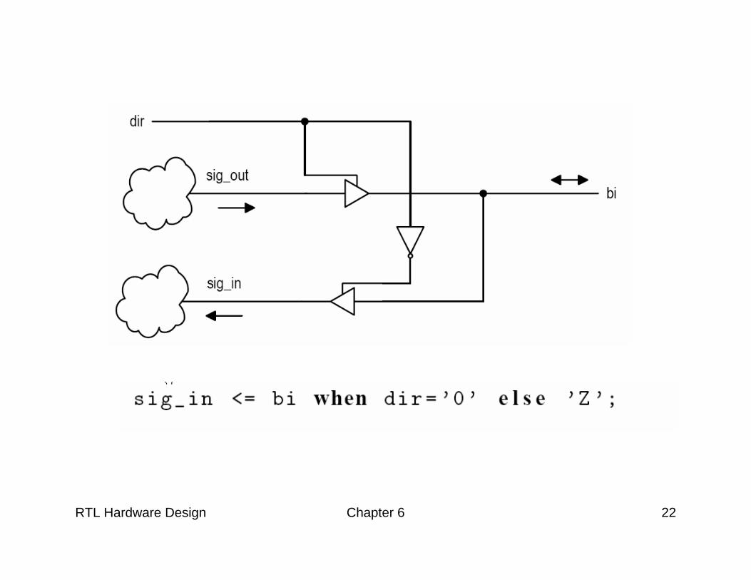
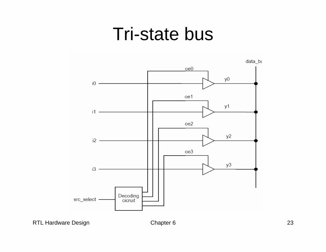
• Major application:– Bi-directional I/O pins– Tri-state bus
• VHDL description:y <= 'Z' when oe='1' else
a_in;• ‘Z’ cannot be used as input or manipulated
f <= 'Z' and a;y <= data_a when in_bus='Z' else
data_b;
RTL Hardware Design Chapter 6 19
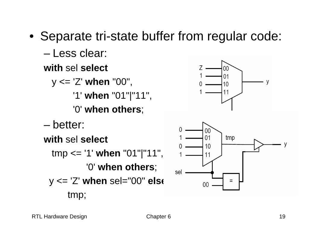
• Separate tri-state buffer from regular code:– Less clear:with sel select
y <= 'Z' when "00",'1' when "01"|"11",'0' when others;
– better:with sel select
tmp <= '1' when "01"|"11",'0' when others;
y <= 'Z' when sel="00" elsetmp;
RTL Hardware Design Chapter 6 20
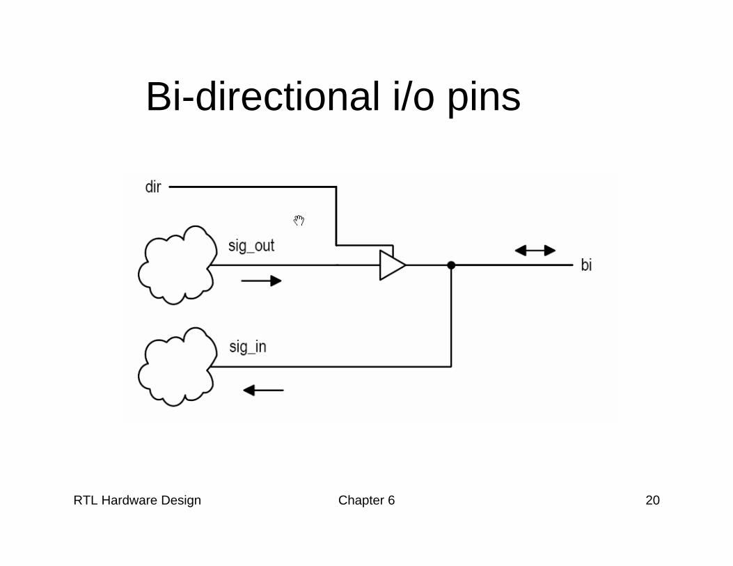
Bi-directional i/o pins
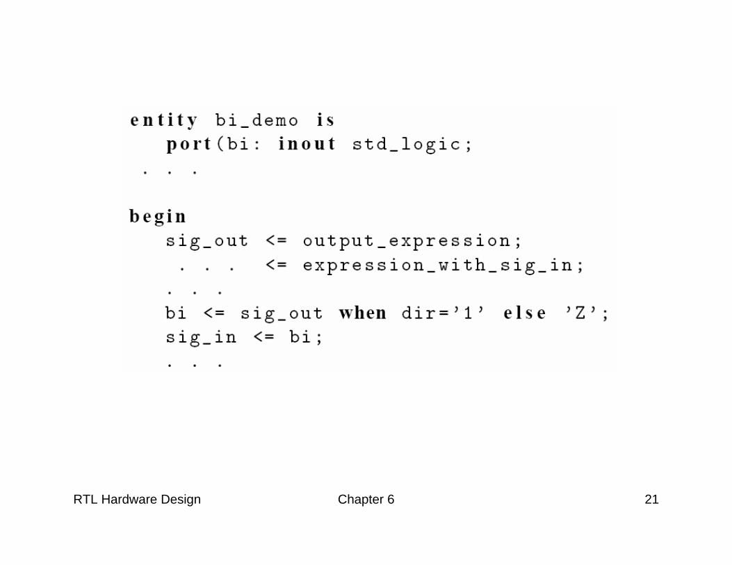
RTL Hardware Design Chapter 6 21
RTL Hardware Design Chapter 6 22
RTL Hardware Design Chapter 6 23
Tri-state bus
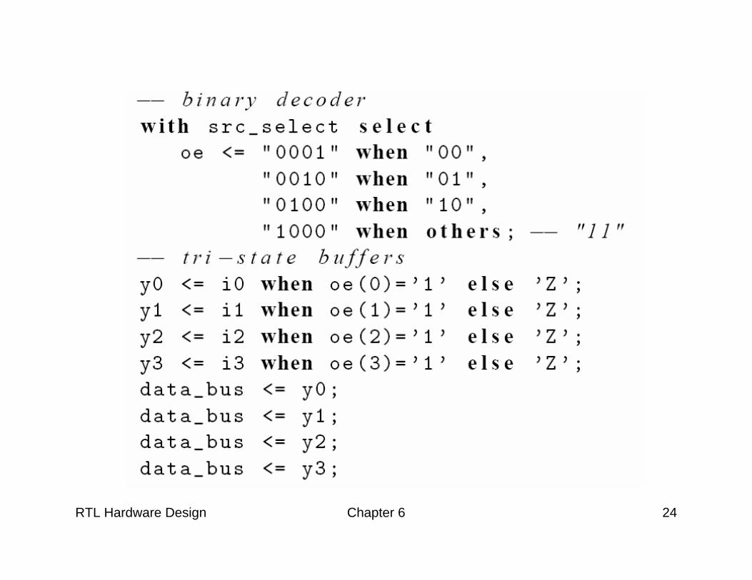
RTL Hardware Design Chapter 6 24
RTL Hardware Design Chapter 6 25
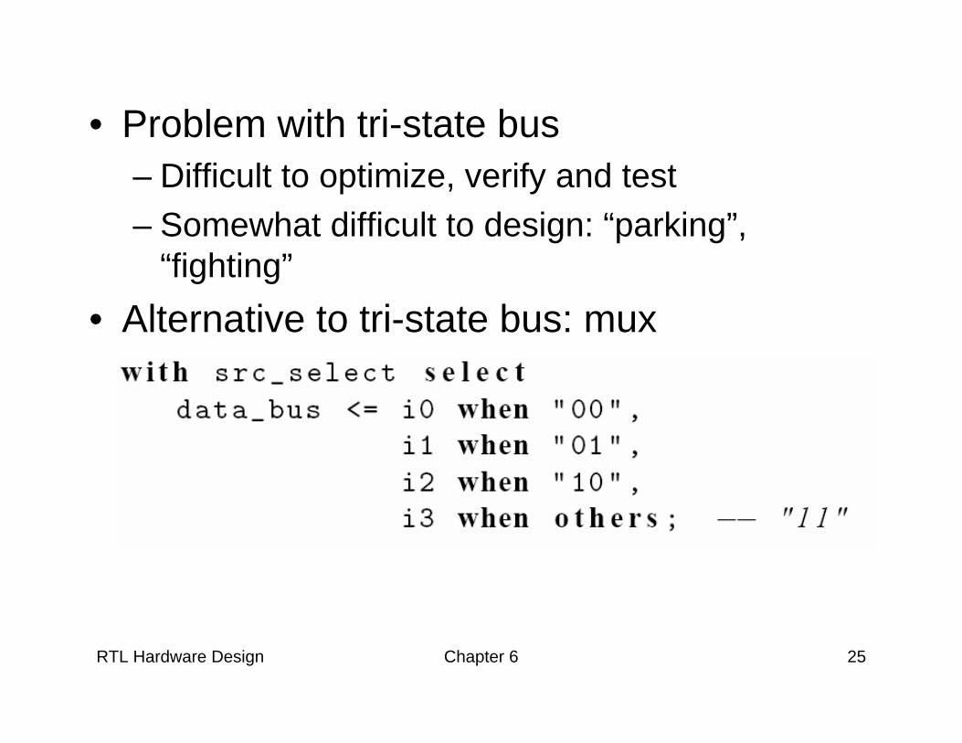
• Problem with tri-state bus– Difficult to optimize, verify and test – Somewhat difficult to design: “parking”,
“fighting” • Alternative to tri-state bus: mux
RTL Hardware Design Chapter 6 26
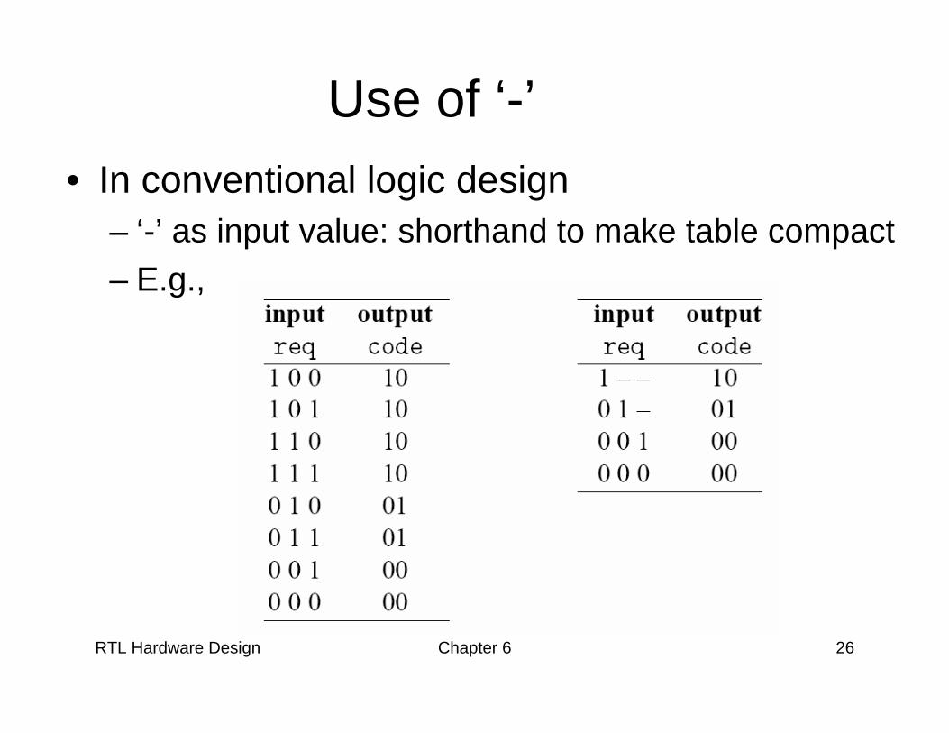
Use of ‘-’• In conventional logic design
– ‘-’ as input value: shorthand to make table compact– E.g.,
RTL Hardware Design Chapter 6 27
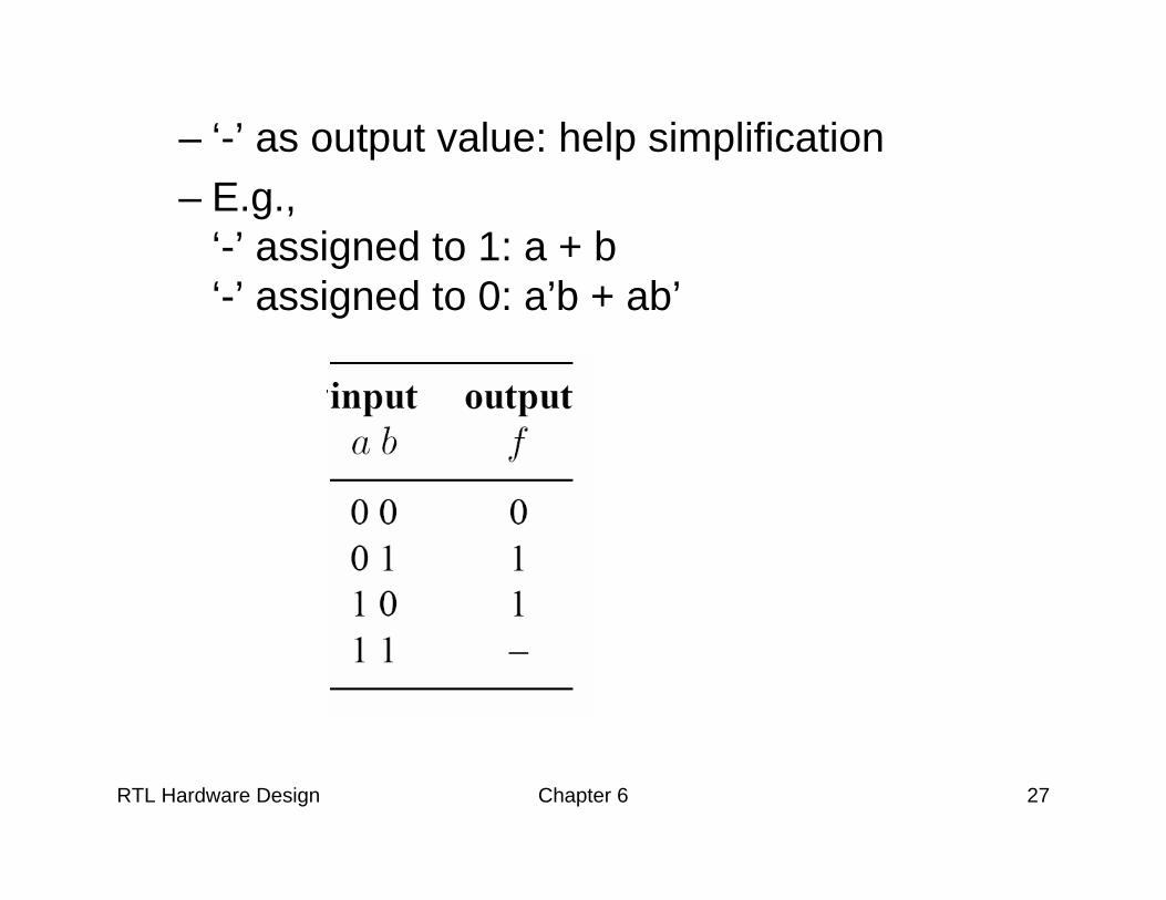
– ‘-’ as output value: help simplification– E.g.,
‘-’ assigned to 1: a + b‘-’ assigned to 0: a’b + ab’
RTL Hardware Design Chapter 6 28
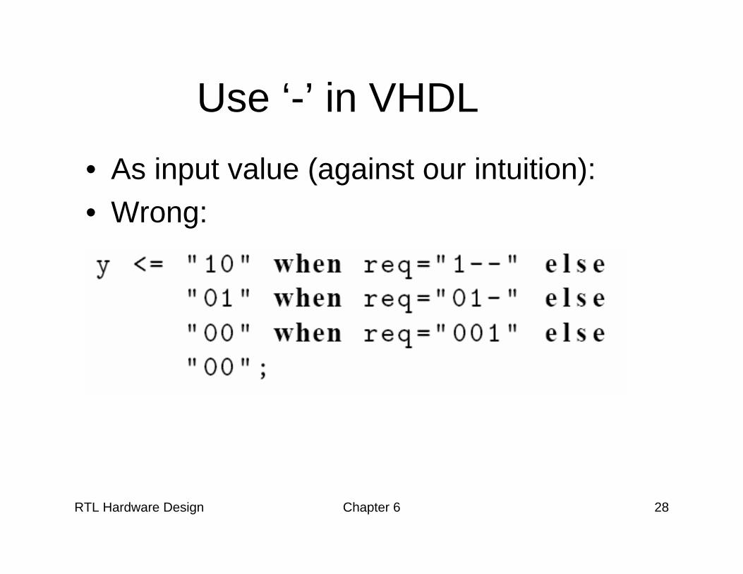
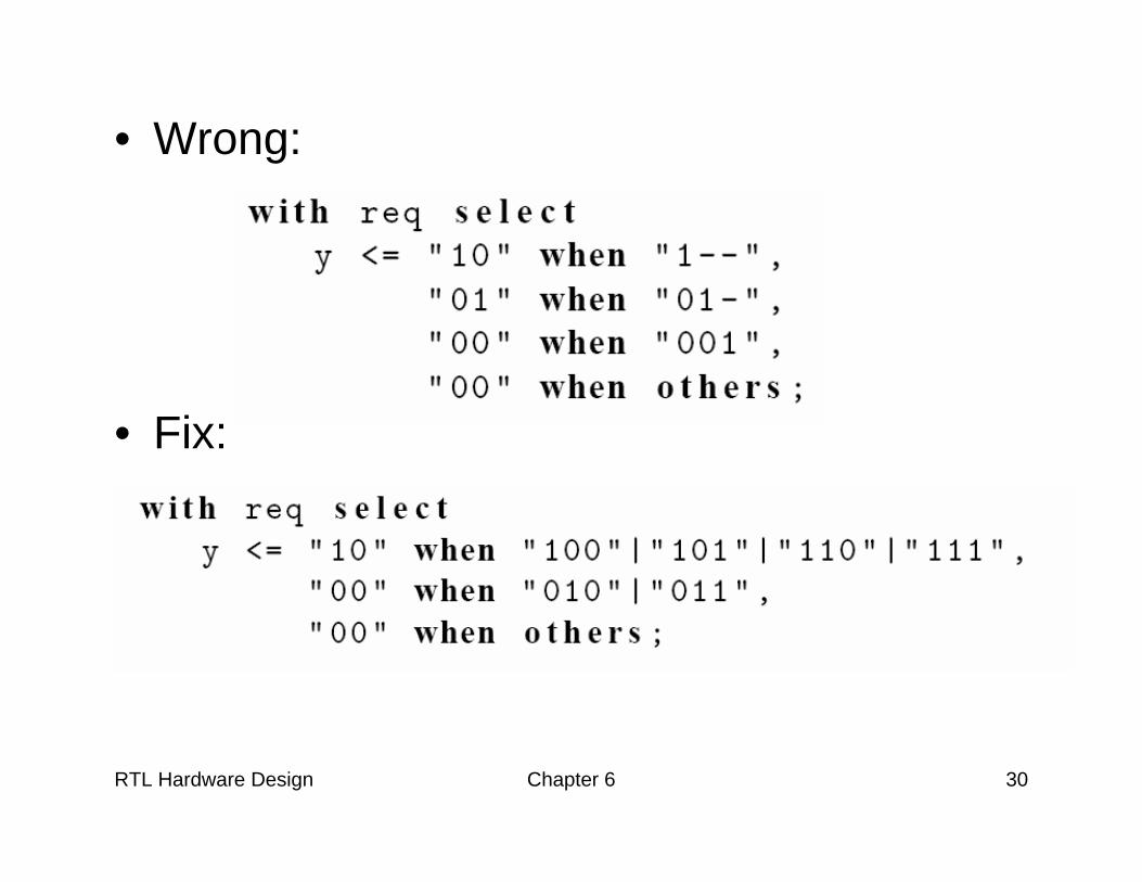
Use ‘-’ in VHDL• As input value (against our intuition):• Wrong:
RTL Hardware Design Chapter 6 29
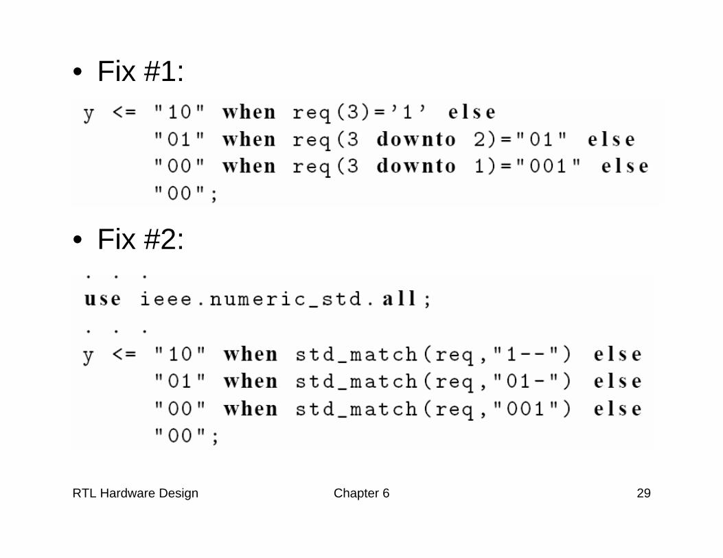
• Fix #1:
• Fix #2:
RTL Hardware Design Chapter 6 30
• Wrong:
• Fix:
RTL Hardware Design Chapter 6 31
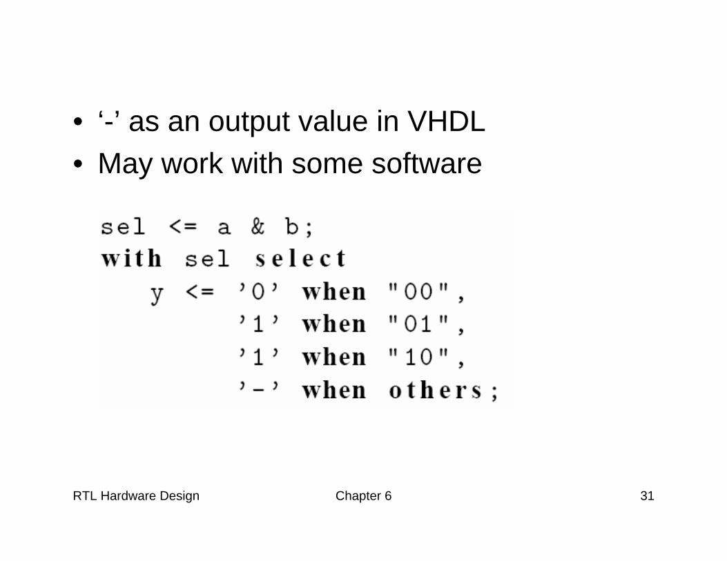
• ‘-’ as an output value in VHDL• May work with some software
RTL Hardware Design Chapter 6 32
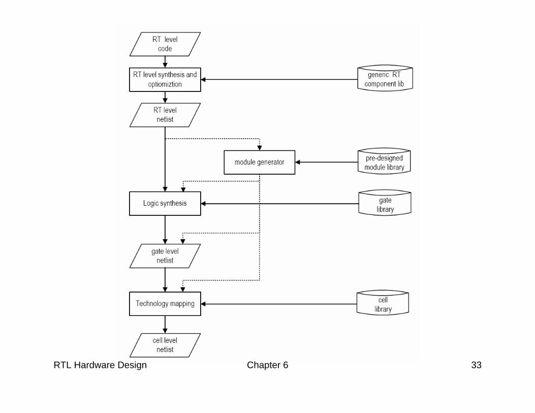
4. VHDL Synthesis Flow
• Synthesis: – Realize VHDL code using logic cells from the
device’s library– a refinement process
• Main steps:– RT level synthesis – Logic synthesis– Technology mapping
RTL Hardware Design Chapter 6 33
RTL Hardware Design Chapter 6 34
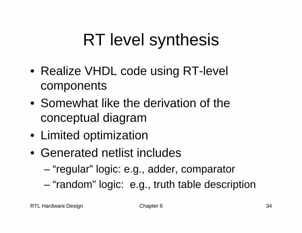
RT level synthesis
• Realize VHDL code using RT-level components
• Somewhat like the derivation of the conceptual diagram
• Limited optimization• Generated netlist includes
– “regular” logic: e.g., adder, comparator– “random” logic: e.g., truth table description
RTL Hardware Design Chapter 6 35
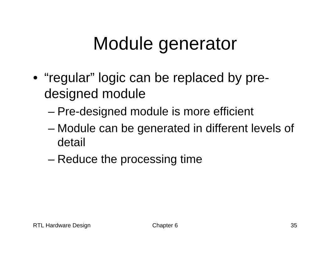
Module generator
• “regular” logic can be replaced by pre-designed module– Pre-designed module is more efficient– Module can be generated in different levels of
detail– Reduce the processing time
RTL Hardware Design Chapter 6 36
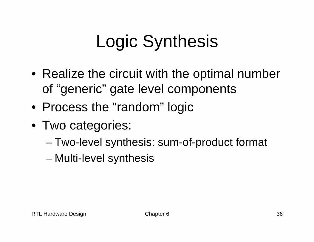
Logic Synthesis
• Realize the circuit with the optimal number of “generic” gate level components
• Process the “random” logic• Two categories:
– Two-level synthesis: sum-of-product format– Multi-level synthesis

RTL Hardware Design Chapter 6 37
• E.g.,
RTL Hardware Design Chapter 6 38
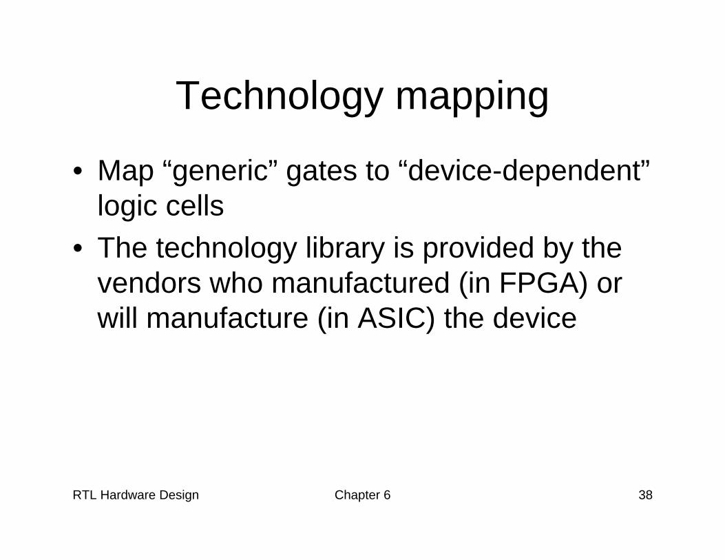
Technology mapping
• Map “generic” gates to “device-dependent” logic cells
• The technology library is provided by the vendors who manufactured (in FPGA) or will manufacture (in ASIC) the device
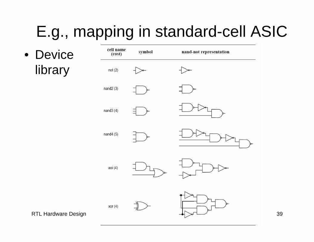
RTL Hardware Design Chapter 6 39
E.g., mapping in standard-cell ASIC • Device
library
RTL Hardware Design Chapter 6 40
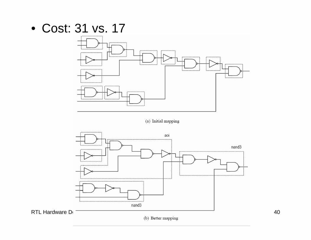
• Cost: 31 vs. 17
RTL Hardware Design Chapter 6 41
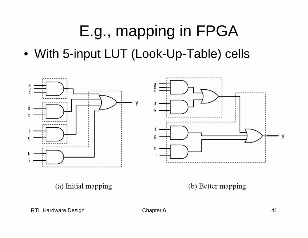
E.g., mapping in FPGA• With 5-input LUT (Look-Up-Table) cells
RTL Hardware Design Chapter 6 42
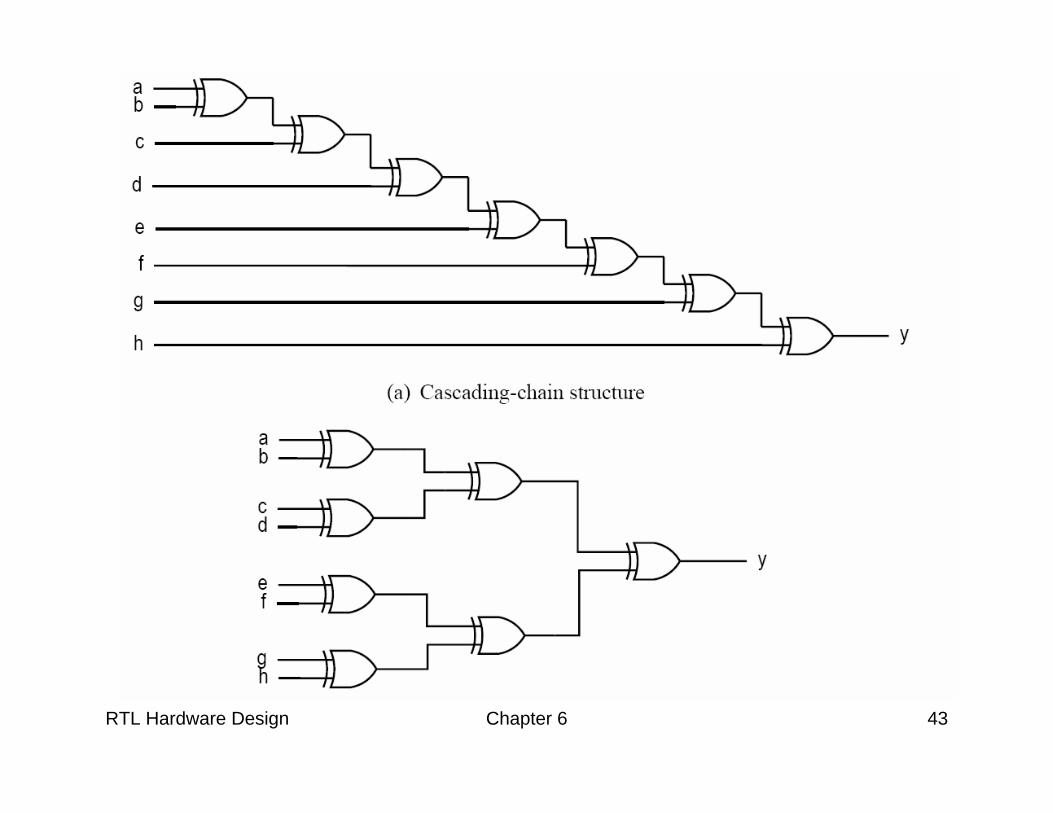
Effective use of synthesis software
• Logic operators: software can do a good job
• Relational/Arith operators: manual intervention needed
• “layout” and “routing structure”: – Silicon chip is 2-dimensional square– “rectangular” or “tree-shaped” circuit is easier
to optimize
RTL Hardware Design Chapter 6 43
RTL Hardware Design Chapter 6 44
5. Timing consideration
• Propagation delay• Synthesis with timing constraint• Hazards• Delay-sensitive design
RTL Hardware Design Chapter 6 45
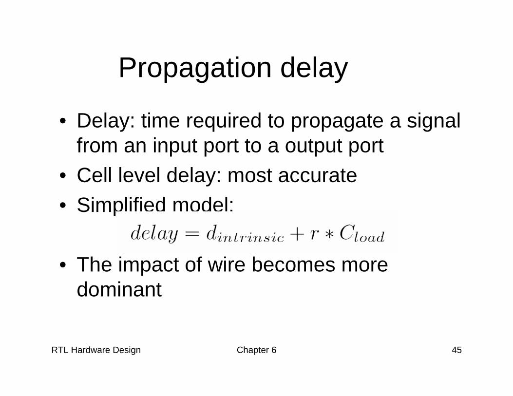
Propagation delay
• Delay: time required to propagate a signal from an input port to a output port
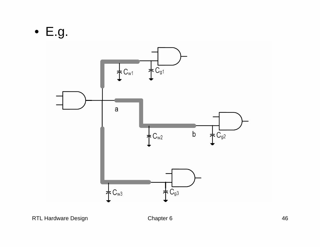
• Cell level delay: most accurate• Simplified model:
• The impact of wire becomes more dominant
RTL Hardware Design Chapter 6 46
• E.g.
RTL Hardware Design Chapter 6 47
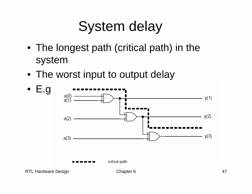
System delay • The longest path (critical path) in the
system• The worst input to output delay• E.g.,

RTL Hardware Design Chapter 6 48
• “False path” may exists:
RTL Hardware Design Chapter 6 49
• RT level delay estimation:– Difficult if the design is mainly “random” logic– Critical path can be identified if many complex
operators (such adder) are used in the design.
RTL Hardware Design Chapter 6 50
Synthesis with timing constraint
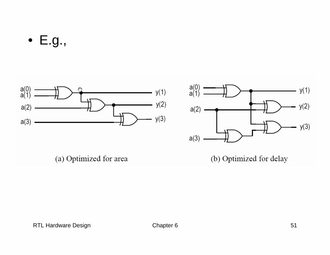
• Multi-level synthesis is flexible• It is possible to reduce by delay by
adding extra logic• Synthesis with timing constraint
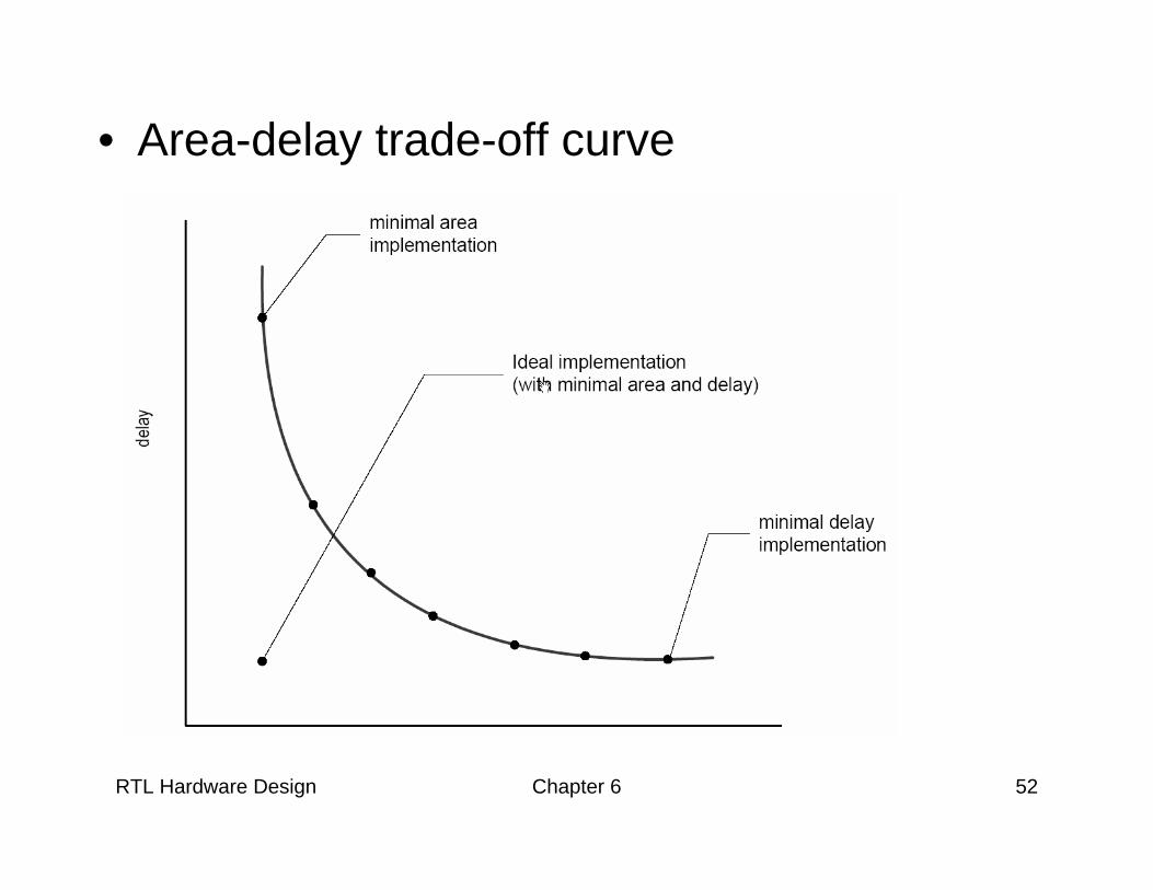
1. Obtain the minimal-area implementation2. Identify the critical path3. Reduce the delay by adding extra logic4. Repeat 2 & 3 until meeting the constraint
RTL Hardware Design Chapter 6 51
• E.g.,
RTL Hardware Design Chapter 6 52
• Area-delay trade-off curve
RTL Hardware Design Chapter 6 53
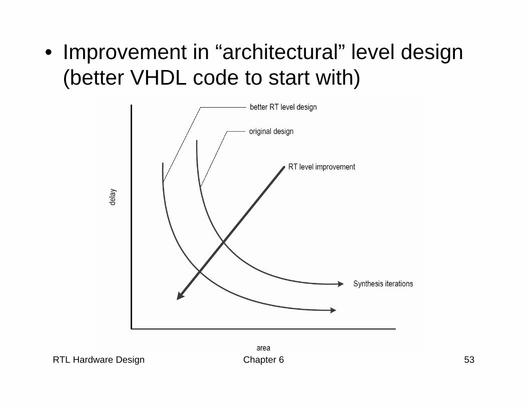
• Improvement in “architectural” level design (better VHDL code to start with)
RTL Hardware Design Chapter 6 54
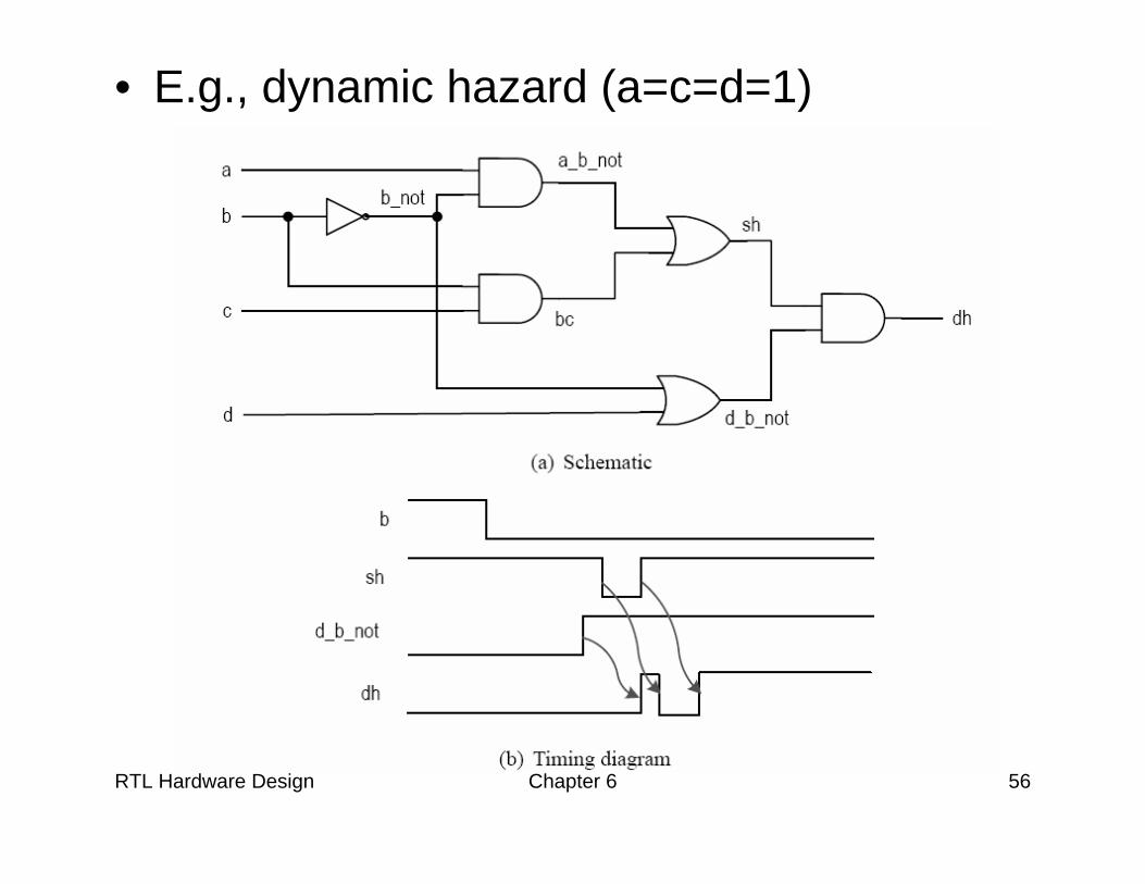
Timing Hazards
• Propagation delay: time to obtain a stable output
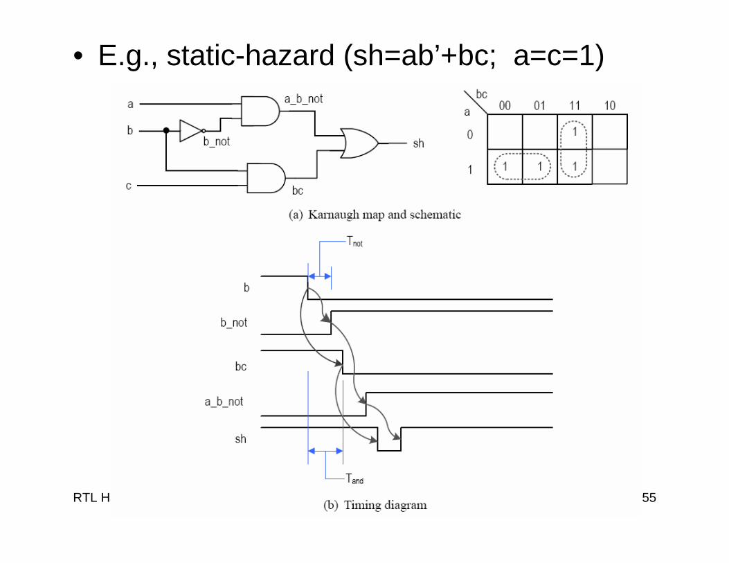
• Hazards: the fluctuation occurring during the transient period – Static hazard: glitch when the signal should
be stable– Dynamic hazard: a glitch in transition
• Due to the multiple converging paths of an output port
RTL Hardware Design Chapter 6 55
• E.g., static-hazard (sh=ab’+bc; a=c=1)
RTL Hardware Design Chapter 6 56
• E.g., dynamic hazard (a=c=d=1)
RTL Hardware Design Chapter 6 57
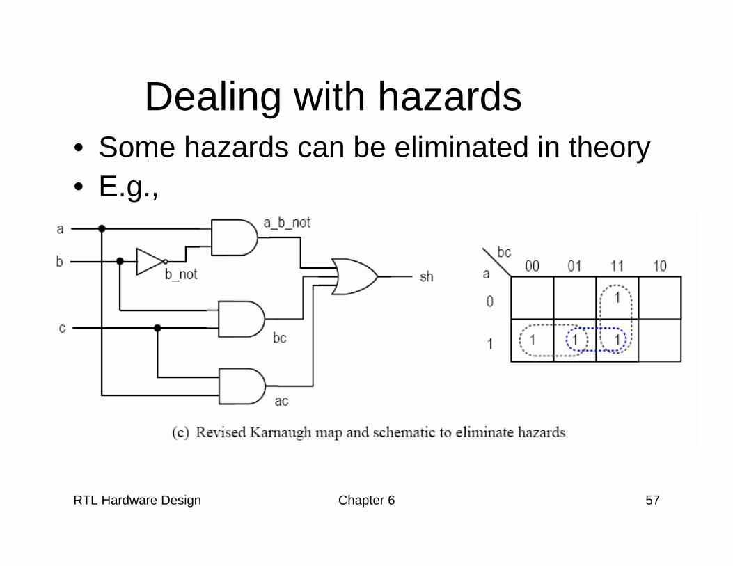
Dealing with hazards• Some hazards can be eliminated in theory • E.g.,
RTL Hardware Design Chapter 6 58
• Eliminating glitches is very difficult in reality, and almost impossible for synthesis
• Multiple inputs can change simultaneously (e.g., 1111=>0000 in a counter)
• How to deal with it? Ignore glitches in the transient period and retrieve the data after the signal is stabilized

RTL Hardware Design Chapter 6 59
Delay sensitive design and its danger
• Boolean algebra – the theoretical model for digital design and
most algorithms used in synthesis process– algebra deals with the stabilized signals
• Delay-sensitive design – Depend on the transient property (and delay)
of the circuit– Difficult to design and analyze
RTL Hardware Design Chapter 6 60
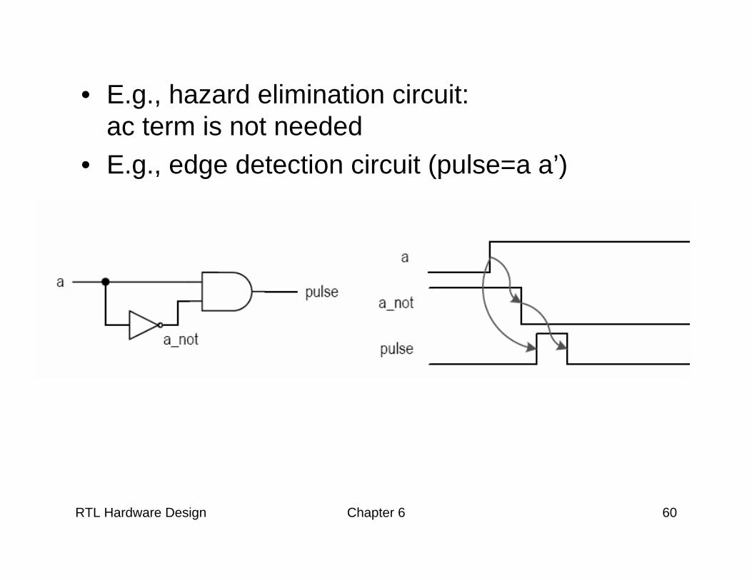
• E.g., hazard elimination circuit: ac term is not needed
• E.g., edge detection circuit (pulse=a a’)
RTL Hardware Design Chapter 6 61
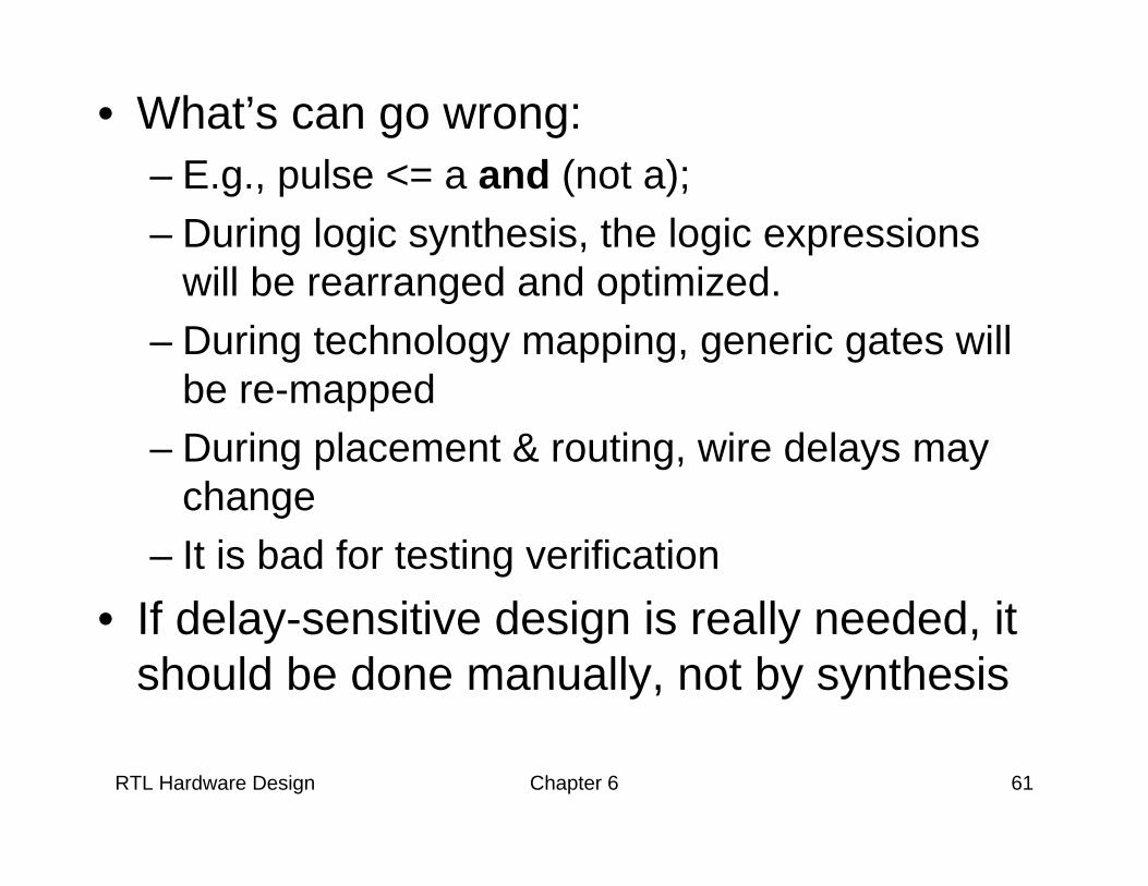
• What’s can go wrong:– E.g., pulse <= a and (not a);– During logic synthesis, the logic expressions
will be rearranged and optimized.– During technology mapping, generic gates will
be re-mapped– During placement & routing, wire delays may
change– It is bad for testing verification
• If delay-sensitive design is really needed, it should be done manually, not by synthesis

![Write VHDL code for half subtractor using data flow modeling. [ 4M] f) Write VHDL code for D Flip Flop with asynchronous reset using behavioral modeling. [ 3M]](https://img.pdfslide.net/doc/110x75/5add12e97f8b9aeb668c687b/-write-vhdl-code-for-half-subtractor-using-data-flow-modeling-4m-f-write.jpg)