Embed Size (px)
Citation preview
Research ArticleSynthesizing Asymmetric Side Lobe Pattern withSteered Nulling in Nonuniformly Excited Linear Arrays byControlling Edge Elements
Jafar RamadhanMohammed and Khalil H Sayidmarie
College of Electronics Engineering Ninevah University Mosul 41001 Iraq
Correspondence should be addressed to Khalil H Sayidmarie khsayidmariegmailcom
Received 12 January 2017 Revised 2 April 2017 Accepted 16 April 2017 Published 24 May 2017
Academic Editor Jaume Anguera
Copyright copy 2017 Jafar Ramadhan Mohammed and Khalil H Sayidmarie This is an open access article distributed under theCreative Commons Attribution License which permits unrestricted use distribution and reproduction in any medium providedthe original work is properly cited
In radar antennas asymmetric side lobes are useful where undesired signals such as noise and ground clutter should beminimizedAlso for practical implementation the feeding network of such antennas should be efficiently designed In this paper a simpleanalytical method for synthesizing asymmetric side lobe pattern with a wide-angle steered null in the nonuniformly excited lineararrays is presented In this method the difference in the side lobe levels on both sides of the main beam is achieved by varying justthe phase excitations of the two-edge elements The major novelty of this paper lies in the fact that the required asymmetric sidelobe pattern can be achieved by changing a single phase shifter resulting in a simple feeding network
1 Introduction
The performance of the radar and communication systemsis highly affected by the level of the interfering signals andground clutter that need to be rejected In general therejection is achieved by synthesizing an array with low sidelobe level or pointing the nulls towards the directions ofinterfering signals or clutter returns Thus the topic of sidelobe reduction or cancellation has attracted much interestin the past and is still of great interest especially with thecurrently crowded spectrum
From the computational complexity of the feed networkpoint of view the methods of side lobe canceling can begrouped into two categories The first is fully controlledarrays [1ndash7] that require full control of weights of all thearray elements while the second is the partially controlledarrays that require few elementsrsquo weight to be controllable[8] In both groups it is much easier to control the phasedistribution of the element excitations than to control theamplitude distribution [9 10] To synthesize an array patternwith specific constraints on the side lobe structure variousoptimization algorithms have been proposed in the literature
These are particle swarm optimization [11 12] genetic algo-rithm [13 14] and simulated annealing [15] or the convexprogramming [16 17] However most of these optimizationalgorithms support the concept of fully controlled arrayswhere the amplitude and phase excitations of all or most ofthe array elements are under control This leads to a complexand expensive feeding network
A simple method for null steering by controlling theamplitude and phase excitations of just the two-edge elementshas previously been described in [18] for uniformly excitedlinear arrays In this paper the method is further extended toobtain a very general strategy that is applicable to uniformlyand nonuniformly excited arrays Moreover a new andsimple analytical model for producing asymmetric patternwith a large difference between the side lobe levels on bothsides of the main beam is presented The amplitude of thetwo-edge elements is adjusted initially then by properlychanging the phase excitations of the two-edge elements ofthe array antenna the asymmetric side lobe pattern can beimplemented and the side lobe nulling can be steered to theleft or right side of the main beam
HindawiInternational Journal of Antennas and PropagationVolume 2017 Article ID 9293031 7 pageshttpsdoiorg10115520179293031
2 International Journal of Antennas and Propagation
Receiver
Amplitude weights
Elements
Plane wave Incident field
Phase shifters
sum
휃
x
A aMA aM a1a1
minus(M minus 12)훽 minus P minus훽2 훽2 (M minus 12)훽 + P
M 1 M1
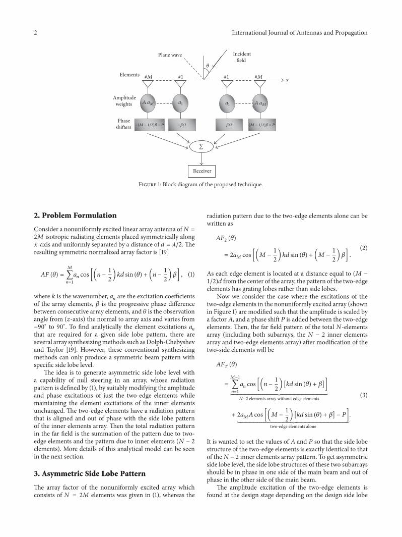
Figure 1 Block diagram of the proposed technique
2 Problem Formulation
Consider a nonuniformly excited linear array antenna of119873 =2119872 isotropic radiating elements placed symmetrically along119909-axis and uniformly separated by a distance of 119889 = 1205822 Theresulting symmetric normalized array factor is [19]
119860119865 (120579) =119872
sum119899=1
119886119899 cos [(119899 minus 12) 119896119889 sin (120579) + (119899 minus12) 120573] (1)
where 119896 is the wavenumber 119886119899 are the excitation coefficientsof the array elements 120573 is the progressive phase differencebetween consecutive array elements and 120579 is the observationangle from (119911-axis) the normal to array axis and varies fromminus90∘ to 90∘ To find analytically the element excitations 119886119899that are required for a given side lobe pattern there areseveral array synthesizingmethods such asDolph-Chebyshevand Taylor [19] However these conventional synthesizingmethods can only produce a symmetric beam pattern withspecific side lobe level
The idea is to generate asymmetric side lobe level witha capability of null steering in an array whose radiationpattern is defined by (1) by suitably modifying the amplitudeand phase excitations of just the two-edge elements whilemaintaining the element excitations of the inner elementsunchanged The two-edge elements have a radiation patternthat is aligned and out of phase with the side lobe patternof the inner elements array Then the total radiation patternin the far field is the summation of the pattern due to two-edge elements and the pattern due to inner elements (119873 minus 2elements) More details of this analytical model can be seenin the next section
3 Asymmetric Side Lobe Pattern
The array factor of the nonuniformly excited array whichconsists of 119873 = 2119872 elements was given in (1) whereas the
radiation pattern due to the two-edge elements alone can bewritten as
1198601198652 (120579)
= 2119886119872 cos [(119872 minus 12) 119896119889 sin (120579) + (119872 minus12)120573]
(2)
As each edge element is located at a distance equal to (119872 minus12)119889 from the center of the array the pattern of the two-edgeelements has grating lobes rather than side lobes
Now we consider the case where the excitations of thetwo-edge elements in the nonuniformly excited array (shownin Figure 1) are modified such that the amplitude is scaled bya factor119860 and a phase shift 119875 is added between the two-edgeelements Then the far field pattern of the total 119873-elementsarray (including both subarrays the 119873 minus 2 inner elementsarray and two-edge elements array) after modification of thetwo-side elements will be
119860119865119879 (120579)
=119872minus1
sum119899=1
119886119899 cos [(119899 minus 12) [119896119889 sin (120579) + 120573]]⏟⏟⏟⏟⏟⏟⏟⏟⏟⏟⏟⏟⏟⏟⏟⏟⏟⏟⏟⏟⏟⏟⏟⏟⏟⏟⏟⏟⏟⏟⏟⏟⏟⏟⏟⏟⏟⏟⏟⏟⏟⏟⏟⏟⏟⏟⏟⏟⏟⏟⏟⏟⏟⏟⏟⏟⏟⏟⏟⏟⏟⏟⏟⏟⏟⏟⏟⏟⏟119873minus2 elements array without edge elements
+ 2119886119872119860 cos [(119872 minus 12) [119896119889 sin (120579) + 120573] minus 119875]⏟⏟⏟⏟⏟⏟⏟⏟⏟⏟⏟⏟⏟⏟⏟⏟⏟⏟⏟⏟⏟⏟⏟⏟⏟⏟⏟⏟⏟⏟⏟⏟⏟⏟⏟⏟⏟⏟⏟⏟⏟⏟⏟⏟⏟⏟⏟⏟⏟⏟⏟⏟⏟⏟⏟⏟⏟⏟⏟⏟⏟⏟⏟⏟⏟⏟⏟⏟⏟⏟⏟⏟⏟⏟⏟⏟⏟⏟⏟⏟⏟two-edge elements alone
(3)
It is wanted to set the values of 119860 and 119875 so that the side lobestructure of the two-edge elements is exactly identical to thatof the119873minus 2 inner elements array pattern To get asymmetricside lobe level the side lobe structures of these two subarraysshould be in phase in one side of the main beam and out ofphase in the other side of the main beam
The amplitude excitation of the two-edge elements isfound at the design stage depending on the design side lobe
International Journal of Antennas and Propagation 3
minus80 minus60 minus40 minus20 0 20 40 60 80
Original Dolph pattern Resulting pattern
minus80 minus60 minus40 minus20 0 20 40 60 80minus1
0
1
2
3
4
5
6
7 A
mpl
itude
Dolph pattren Two-edge pattren Resulting pattern
휃 (degrees) 휃 (degrees)
minus30minus25minus20minus15minus10minus5
05
101520
Pow
er p
atte
rn (d
B)
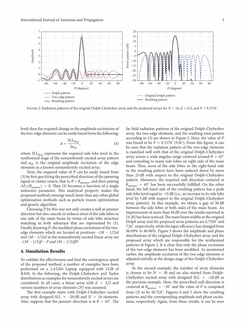
Figure 2 Radiation patterns of the original Dolph-Chebyshev array and the proposed arrays for119873 = 16 119889 = 1205822 and 119875 = 91576∘
level then the required change in the amplitude excitations ofthe two-edge elements can be easily found from the following
119860 = SLLReq2119886119872 (4)
where SLLReq represents the required side lobe level in thesynthesized stage of the nonuniformly excited array patternand 119886119872 is the original amplitude excitation of the edgeelements in a known nonuniformly excited array
Next the required value of 119875 can be easily found from(3) by first specifying the prescribed direction of the jammingsignal or clutter return that is 120579 = 120579jammer and then putting119860119865119879(120579jammer) = 0 Thus (3) becomes a function of a singleunknown parameter This analytical property makes theproposedmethod convergemuch faster than any other globaloptimization methods such as particle swarm optimizationand genetic algorithm
Choosing 119875 by this way not only creates a null at jammerdirection but also cancels or reduces most of the side lobes inone side of the main beam by virtue of side lobe structurematching in both subarrays that are represented by (3)Finally knowing119875 themodified phase excitations of the two-edge elements which are located at positions minus(119872 minus 12)119889and (119872 minus 12)119889 in the nonuniformly excited linear array areminus(119872 minus 12)120573 minus 119875 and (119872 minus 12)1205731198754 Simulation Results
To validate the effectiveness and find the convergence speedof the proposed method a number of examples have beenperformed on a 24GHz Laptop equipped with 2GB ofRAM In the following the Dolph-Chebyshev and Taylordistributions as examples for nonuniformly excited arrays areconsidered In all cases a linear array with 119889 = 1205822 andvarious numbers of array elements (119873) was assumed
The first example starts with Dolph-Chebyshev excitedarray with designed SLL = minus20 dB and 119873 = 16 elementsAlso suppose that the jammer direction is at 120579 = 65∘ The
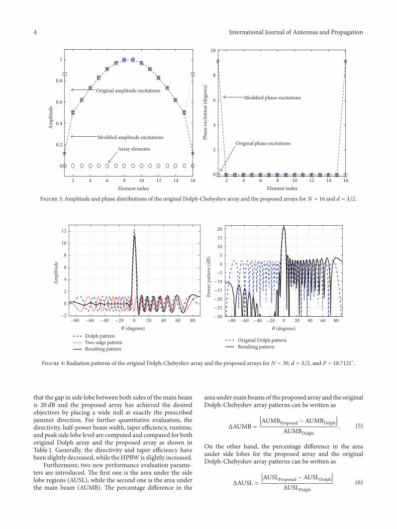
far field radiation patterns of the original Dolph-Chebyshevarray the two-edge elements and the resulting total patternaccording to (3) are shown in Figure 2 Here the value of 119875was found to be 119875 = 91576∘ (916∘) From this figure it canbe seen that the radiation pattern of the two-edge elementsis matched well with that of the original Dolph-Chebyshevarray across a wide angular range centered around 120579 = 65∘and extending to many side lobes on right side of the mainbeam Thus most of the side lobes in the right-hand sidein the resulting pattern have been reduced down by morethan 25 dB with respect to the original Dolph-Chebyshevpattern Moreover the required null direction centered at120579jammer = 65∘ has been successfully fulfilled On the otherhand the left-hand side of the resulting pattern has a peakside lobe level equal to minus15 dB (ie an increase in its side lobelevel by 5 dB with respect to the original Dolph-Chebyshevarray pattern) In this example we obtain a gap of 30 dBbetween the side lobes at both sides of the main beam Animprovement of more than 10 dB over the results reported in[9 10] has been noticedThemain beamwidths in the originalDolph array and the proposed array patterns are 67520∘ and726∘ respectively while the taper efficiency has changed from9609 to 8686 Figure 3 shows the amplitude and phasedistributions of the original Dolph-Chebyshev array and theproposed array which are responsible for the synthesizedpatterns of Figure 2 It is clear that only the phase excitationof the two-edge elements has been modified As mentionedearlier the amplitude excitation of the two-edge elements isadjusted initially at the design stage of the Dolph-Chebyshevarray
In the second example the number of array elementsis chosen to be 119873 = 30 and we also started from Dolph-Chebyshev excited array with designed SLL = minus20 dB asthe previous example Here the prescribed null direction iscentered at 120579jammer = minus30∘ and the value of 119875 is computedfrom (3) to be 187121∘ Figures 4 and 5 show the resultingpatterns and the corresponding amplitude and phase excita-tions respectively Again from these results it can be seen
4 International Journal of Antennas and Propagation
Array elementsOriginal phase excitations
Modified phase excitationsOriginal amplitude excitations
Modified amplitude excitations
0
02
04
06
08
1 A
mpl
itude
4 6 8 10 12 14 162 Element index
4 6 8 10 12 14 162 Element index
0
2
4
6
8
10
Pha
se ex
cita
tion
(deg
rees
)Figure 3 Amplitude and phase distributions of the original Dolph-Chebyshev array and the proposed arrays for119873 = 16 and 119889 = 1205822
minus80 minus60 minus40 minus20 0 20 40 60 80
Dolph pattren Two-edge pattren Resulting pattern
휃 (degrees)
minus2
0
2
4
6
8
10
12
Am
plitu
de
minus80 minus60 minus40 minus20 0 20 40 60 80
Original Dolph pattern Resulting pattern
휃 (degrees)
minus30minus25minus20minus15minus10minus5
05
101520
Pow
er p
atte
rn (d
B)
Figure 4 Radiation patterns of the original Dolph-Chebyshev array and the proposed arrays for119873 = 30 119889 = 1205822 and 119875 = 187121∘
that the gap in side lobe between both sides of the main beamis 20 dB and the proposed array has achieved the desiredobjectives by placing a wide null at exactly the prescribedjammer direction For further quantitative evaluation thedirectivity half-power beam width taper efficiency runtimeand peak side lobe level are computed and compared for bothoriginal Dolph array and the proposed array as shown inTable 1 Generally the directivity and taper efficiency havebeen slightly decreased while theHPBW is slightly increased
Furthermore two new performance evaluation parame-ters are introduced The first one is the area under the sidelobe regions (AUSL) while the second one is the area underthe main beam (AUMB) The percentage difference in the
area undermain beams of the proposed array and the originalDolph-Chebyshev array patterns can be written as
ΔAUMB =10038161003816100381610038161003816AUMBProposed minus AUMBDolph
10038161003816100381610038161003816AUMBDolph
(5)
On the other hand the percentage difference in the areaunder side lobes for the proposed array and the originalDolph-Chebyshev array patterns can be written as
ΔAUSL =10038161003816100381610038161003816AUSLProposed minus AUSLDolph
10038161003816100381610038161003816AUSLDolph
(6)
International Journal of Antennas and Propagation 5
0
05
1
15
Am
plitu
deOriginal Dolph excitations
Modified Dolph excitationsElements array
Modified Dolph excitations
Original Dolph excitations
5 10 2015 25 30 Element index
105 2015 25 30 Element index
0
5
10
15
20
Pha
se ex
cita
tion
(deg
rees
)Figure 5 Amplitude and phase distributions of the original Dolph-Chebyshev array and the proposed arrays for119873 = 30 and 119889 = 1205822
Table 1 Patterns features for different number of array elements119873 and 119889 = 1205822
Features Original Dolph array pattern Proposed array pattern(change with respect to original Dolph pattern)
119873 = 10 119873 = 16 119873 = 30 119873 = 10 119873 = 16 119873 = 30Directivity [dB] 98441 118794 144222 95102
(minus334)115210
(minus302)141047(minus22)
HPBW [deg] 111520 67520 35200 118200(598)
726(75)
38700(99)
Taper efficiency 09622 09609 09207 08404(minus126)
08686(minus96)
08955(minus27)
Runtime [second] 175756 183548 187657 175756(00)
183548(00)
187657(00)
Peak SLL [dB] minus20 minus20 minus20 minus151(49 dB)
minus157(43 dB)
minus167(33 dB)
AUSL 00442 00531 00683 00343 00290 00238ΔAUSL mdash mdash mdash (minus224) (minus4538) (minus6515)AUMB 0262 01796 00917 02890 01935 00981ΔAUMB mdash mdash mdash (103) (774) (697)
These areas are computed and compared for various scenariosas shown in Table 1 As expected the value of AUMBProposedis slightly larger than that of AUMBDolph while AUSLProposedis much smaller than that of AUSLDolph This fully confirmsthe effectiveness of the proposed array More importantly thevalue of ΔAUSL is increasing with larger number of arrayelements (119873) while the value of ΔAUMB is decreasing
In the next example we start from a Taylor excited arraywith designed SLL = minus20 dB and 119873 = 16 elements Theresulting patterns are shown in Figure 6 which clearly showsthat the required null position centered at 120579jammer = 20∘ has
been achieved and a gap of 20 dB in the side lobe betweenboth sides of the main beam has been obtained Here thevalue of 119875 was found to be 119875 = 675∘
Finally for a real examination we used a 16-elementlinear array of half-wavelength dipoles over a simulatedfinite ground plane based on wire grid model as shownin Figure 7(a) and obtained active element patterns using4NEC2 4NEC2 is an efficient tool for modeling these thindipoles in free space and exploring the array performanceincluding the effects of mutual coupling In this structurewe assumed a vertical array of 16 horizontal half-wavelength
6 International Journal of Antennas and Propagation
minus80 minus60 minus40 minus20 0 20 40 60 80
Original Taylor pattern Resulting pattern
휃 (degrees)
minus30
minus25
minus20
minus15
minus10
minus5
0
5
10
15
20
Pow
er p
atte
rn (d
B)
Figure 6 Radiation patterns of the original Taylor pattern and theproposed arrays for119873 = 16 119889 = 1205822 and 119875 = 675∘
(a)
minus50minus45minus40minus35minus30minus25minus20minus15minus10minus5 0
(dBi
)
Original Dolph arrayProposed array
20 40 60 80 100 120 140 160 180 0Theta
16-Element Dolph array over ground plane far field (Phi = 0)
(b)
Figure 7 (a) Configuration of an array with 16 dipoles over groundplane (b) Radiation patterns of the original Dolph pattern and theproposed arrays Center frequency = 1GHz
dipoles (for the design frequency of 1 GHz then the length ofeach dipole in free space is equal to 150mm) Such arrange-ment of horizontal dipoles will have significant broadsidecoupling between the elements
In the 4NEC2 model of the Dolph excited array eachdipole was divided into 21 segments and a voltage sourceassigned to the center segment (segment 11) of each dipoleThis allowed the specific amplitude and phase excitationsto be applied to the individual elements In this modelthe Dolph-Chebyshev excited array with designed SLL =minus20 dB and119873 = 16 dipoles is considered Figure 7(b) showsthe original Dolph pattern and the resulting pattern withasymmetric side lobe level These patterns are of coursedifferent from those in Figure 2 due to the mutual couplingeffect and the active element pattern
5 Conclusions
The problem of producing wide tunable nulls along withasymmetric side lobe pattern in nonuniformly excited lineararrays using simple analytical model has been addressedThewide null and asymmetric side lobe pattern are accomplishedby reusing edge elements of the array whose radiation patternapproximates that of the side lobe pattern of the mainarray over a wide angular range The proposed array wasapplied to a Dolph-Chebyshev distribution as well as Taylordistribution and achieved differences in the side lobe level onboth sides of the main beam as great as 20 dB Almost samebeam width and directivity were noticed as compared withoriginal Dolph-Chebyshev arrays The other advantage ofthe proposed analytical method over the global optimizationmethods is its ability to offer faster solution and simplerimplementationThe basic principle of the proposed methodcan be extended to other nonuniformly excited linear orplanar arrays
Conflicts of Interest
The authors declare that they have no conflicts of interest
References
[1] R A Monzingo R L Haupt and T W Miller Introduction toAdaptive Arrays SciTech Publishing 2nd edition 2011
[2] V S S S C Vedula S R C Paladuga and M R Prithvi ldquoSyn-thesis of circular array antenna for sidelobe level and aperturesize control using flower pollination algorithmrdquo InternationalJournal of Antennas and Propagation vol 2015 Article ID819712 2015
[3] Y Gong L Wang R Yao and Z Zhang ldquoA robust methodto suppress jamming for GNSS array antenna based on recon-struction of sample covariance matrixrdquo International Journal ofAntennas and Propagation vol 2017 pp 1ndash12 2017
[4] DRMorgan andAAridgides ldquoAdaptive SidelobeCancellationof Wide-Band Multipath Interferencerdquo IEEE Transactions onAntennas and Propagation vol 33 no 8 pp 908ndash917 1985
[5] Q Guo and L Qi ldquoCascaded multitype interferences suppres-sion method using sparse representation and array processingfor GNSS receiverrdquo International Journal of Antennas andPropagation vol 2017 pp 1ndash17 2017
International Journal of Antennas and Propagation 7
[6] S Todnatee and C Phongcharoenpanich ldquoIterative GA opti-mization scheme for synthesis of radiation pattern of lineararray antennardquo International Journal of Antennas and Propaga-tion vol 2016 Article ID 7087298 2016
[7] Y Han and J Wang ldquoAdaptive beam forming based on com-pressed sensing with smoothedrdquo vol 2015 2015
[8] I El-Azhary M S Afifi and P S Excell ldquoSimple algorithm forsidelobe cancellation in a partially adaptive linear arrayrdquo IEEETransactions on Antennas and Propagation vol 36 no 10 pp1484ndash1486 1988
[9] A Trastoy F Ares and E Moreno ldquoPhase-only control ofantenna sum and shaped patterns through null perturbationrdquoIEEEAntennas and PropagationMagazine vol 43 no 6 pp 45ndash54 2001
[10] A Trastoy and F Ares ldquoPhase-only synthesis of continuouslinear aperture distribution patterns with asymmetric sidelobesrdquo Electronics Letters vol 34 no 20 pp 1916-1917 1998
[11] M M Khodier and C G Christodoulou ldquoLinear array geom-etry synthesis with minimum sidelobe level and null controlusing particle swarm optimizationrdquo IEEE Transactions onAntennas and Propagation vol 53 no 8 pp 2674ndash2679 2005
[12] M A Mangoud and H M Elragal ldquoAntenna array patternsynthesis and wide null control using enhanced particle swarmoptimizationrdquo Progress In Electromagnetics Research B no 17pp 1ndash14 2009
[13] M Dawoud A Tennant and A Anderson ldquoNull steering inadaptive arrays using a genetic algorithmrdquo in 24th EuropeanMicrowave Conference 1994 pp 1108ndash1114 Cannes FranceOctober 1994
[14] H Steyskal R A Shore and R L Haupt ldquoMethods for nullcontrol and their effects on the radiation patternrdquo IEEE Trans-actions onAntennas and Propagation vol AP-34 no 3 pp 404ndash409 1986
[15] S K Smith J C Bregains K L Melde and F Ares ldquoAcomparison of optimization techniques for power patterns withlow sidelobes generated by linear arrays with efficient excitationdistributionsrdquo Microwave and Optical Technology Letters vol45 no 1 pp 57ndash60 2005
[16] S Kwak J Chun D Park Y K Ko and B L Cho ldquoAsymmetricsum and difference beam pattern synthesis with a commonweight vectorrdquo IEEE Antennas andWireless Propagation Lettersvol 15 pp 1622ndash1625 2016
[17] A F Morabito and P Rocca ldquoOptimal synthesis of sum anddifference patterns with arbitrary sidelobes subject to commonexcitations constraintsrdquo IEEE Antennas and Wireless Propaga-tion Letters vol 9 pp 623ndash626 2010
[18] J R Mohammed and K H Sayidmarie ldquoNull steering methodby controlling two elementsrdquo IET Microwaves Antennas ampPropagation vol 8 no 15 pp 1348ndash1355 2014
[19] C A Balanis Antenna theory Analysis and Design John WileySons Hoboken New Jersey 3rd edition 2005
RoboticsJournal of
Hindawi Publishing Corporationhttpwwwhindawicom Volume 2014
Hindawi Publishing Corporationhttpwwwhindawicom Volume 2014
Active and Passive Electronic Components
Control Scienceand Engineering
Journal of
Hindawi Publishing Corporationhttpwwwhindawicom Volume 2014
International Journal of
RotatingMachinery
Hindawi Publishing Corporationhttpwwwhindawicom Volume 2014
Hindawi Publishing Corporation httpwwwhindawicom
Journal of
Volume 201
Submit your manuscripts athttpswwwhindawicom
VLSI Design
Hindawi Publishing Corporationhttpwwwhindawicom Volume 201
Hindawi Publishing Corporationhttpwwwhindawicom Volume 2014
Shock and Vibration
Hindawi Publishing Corporationhttpwwwhindawicom Volume 2014
Civil EngineeringAdvances in
Acoustics and VibrationAdvances in
Hindawi Publishing Corporationhttpwwwhindawicom Volume 2014
Hindawi Publishing Corporationhttpwwwhindawicom Volume 2014
Electrical and Computer Engineering
Journal of
Advances inOptoElectronics
Hindawi Publishing Corporation httpwwwhindawicom
Volume 2014
The Scientific World JournalHindawi Publishing Corporation httpwwwhindawicom Volume 2014
SensorsJournal of
Hindawi Publishing Corporationhttpwwwhindawicom Volume 2014
Modelling amp Simulation in EngineeringHindawi Publishing Corporation httpwwwhindawicom Volume 2014
Hindawi Publishing Corporationhttpwwwhindawicom Volume 2014
Chemical EngineeringInternational Journal of Antennas and
Propagation
International Journal of
Hindawi Publishing Corporationhttpwwwhindawicom Volume 2014
Hindawi Publishing Corporationhttpwwwhindawicom Volume 2014
Navigation and Observation
International Journal of
Hindawi Publishing Corporationhttpwwwhindawicom Volume 2014
DistributedSensor Networks
International Journal of
2 International Journal of Antennas and Propagation
Receiver
Amplitude weights
Elements
Plane wave Incident field
Phase shifters
sum
휃
x
A aMA aM a1a1
minus(M minus 12)훽 minus P minus훽2 훽2 (M minus 12)훽 + P
M 1 M1
Figure 1 Block diagram of the proposed technique
2 Problem Formulation
Consider a nonuniformly excited linear array antenna of119873 =2119872 isotropic radiating elements placed symmetrically along119909-axis and uniformly separated by a distance of 119889 = 1205822 Theresulting symmetric normalized array factor is [19]
119860119865 (120579) =119872
sum119899=1
119886119899 cos [(119899 minus 12) 119896119889 sin (120579) + (119899 minus12) 120573] (1)
where 119896 is the wavenumber 119886119899 are the excitation coefficientsof the array elements 120573 is the progressive phase differencebetween consecutive array elements and 120579 is the observationangle from (119911-axis) the normal to array axis and varies fromminus90∘ to 90∘ To find analytically the element excitations 119886119899that are required for a given side lobe pattern there areseveral array synthesizingmethods such asDolph-Chebyshevand Taylor [19] However these conventional synthesizingmethods can only produce a symmetric beam pattern withspecific side lobe level
The idea is to generate asymmetric side lobe level witha capability of null steering in an array whose radiationpattern is defined by (1) by suitably modifying the amplitudeand phase excitations of just the two-edge elements whilemaintaining the element excitations of the inner elementsunchanged The two-edge elements have a radiation patternthat is aligned and out of phase with the side lobe patternof the inner elements array Then the total radiation patternin the far field is the summation of the pattern due to two-edge elements and the pattern due to inner elements (119873 minus 2elements) More details of this analytical model can be seenin the next section
3 Asymmetric Side Lobe Pattern
The array factor of the nonuniformly excited array whichconsists of 119873 = 2119872 elements was given in (1) whereas the
radiation pattern due to the two-edge elements alone can bewritten as
1198601198652 (120579)
= 2119886119872 cos [(119872 minus 12) 119896119889 sin (120579) + (119872 minus12)120573]
(2)
As each edge element is located at a distance equal to (119872 minus12)119889 from the center of the array the pattern of the two-edgeelements has grating lobes rather than side lobes
Now we consider the case where the excitations of thetwo-edge elements in the nonuniformly excited array (shownin Figure 1) are modified such that the amplitude is scaled bya factor119860 and a phase shift 119875 is added between the two-edgeelements Then the far field pattern of the total 119873-elementsarray (including both subarrays the 119873 minus 2 inner elementsarray and two-edge elements array) after modification of thetwo-side elements will be
119860119865119879 (120579)
=119872minus1
sum119899=1
119886119899 cos [(119899 minus 12) [119896119889 sin (120579) + 120573]]⏟⏟⏟⏟⏟⏟⏟⏟⏟⏟⏟⏟⏟⏟⏟⏟⏟⏟⏟⏟⏟⏟⏟⏟⏟⏟⏟⏟⏟⏟⏟⏟⏟⏟⏟⏟⏟⏟⏟⏟⏟⏟⏟⏟⏟⏟⏟⏟⏟⏟⏟⏟⏟⏟⏟⏟⏟⏟⏟⏟⏟⏟⏟⏟⏟⏟⏟⏟⏟119873minus2 elements array without edge elements
+ 2119886119872119860 cos [(119872 minus 12) [119896119889 sin (120579) + 120573] minus 119875]⏟⏟⏟⏟⏟⏟⏟⏟⏟⏟⏟⏟⏟⏟⏟⏟⏟⏟⏟⏟⏟⏟⏟⏟⏟⏟⏟⏟⏟⏟⏟⏟⏟⏟⏟⏟⏟⏟⏟⏟⏟⏟⏟⏟⏟⏟⏟⏟⏟⏟⏟⏟⏟⏟⏟⏟⏟⏟⏟⏟⏟⏟⏟⏟⏟⏟⏟⏟⏟⏟⏟⏟⏟⏟⏟⏟⏟⏟⏟⏟⏟two-edge elements alone
(3)
It is wanted to set the values of 119860 and 119875 so that the side lobestructure of the two-edge elements is exactly identical to thatof the119873minus 2 inner elements array pattern To get asymmetricside lobe level the side lobe structures of these two subarraysshould be in phase in one side of the main beam and out ofphase in the other side of the main beam
The amplitude excitation of the two-edge elements isfound at the design stage depending on the design side lobe
International Journal of Antennas and Propagation 3
minus80 minus60 minus40 minus20 0 20 40 60 80
Original Dolph pattern Resulting pattern
minus80 minus60 minus40 minus20 0 20 40 60 80minus1
0
1
2
3
4
5
6
7 A
mpl
itude
Dolph pattren Two-edge pattren Resulting pattern
휃 (degrees) 휃 (degrees)
minus30minus25minus20minus15minus10minus5
05
101520
Pow
er p
atte
rn (d
B)
Figure 2 Radiation patterns of the original Dolph-Chebyshev array and the proposed arrays for119873 = 16 119889 = 1205822 and 119875 = 91576∘
level then the required change in the amplitude excitations ofthe two-edge elements can be easily found from the following
119860 = SLLReq2119886119872 (4)
where SLLReq represents the required side lobe level in thesynthesized stage of the nonuniformly excited array patternand 119886119872 is the original amplitude excitation of the edgeelements in a known nonuniformly excited array
Next the required value of 119875 can be easily found from(3) by first specifying the prescribed direction of the jammingsignal or clutter return that is 120579 = 120579jammer and then putting119860119865119879(120579jammer) = 0 Thus (3) becomes a function of a singleunknown parameter This analytical property makes theproposedmethod convergemuch faster than any other globaloptimization methods such as particle swarm optimizationand genetic algorithm
Choosing 119875 by this way not only creates a null at jammerdirection but also cancels or reduces most of the side lobes inone side of the main beam by virtue of side lobe structurematching in both subarrays that are represented by (3)Finally knowing119875 themodified phase excitations of the two-edge elements which are located at positions minus(119872 minus 12)119889and (119872 minus 12)119889 in the nonuniformly excited linear array areminus(119872 minus 12)120573 minus 119875 and (119872 minus 12)1205731198754 Simulation Results
To validate the effectiveness and find the convergence speedof the proposed method a number of examples have beenperformed on a 24GHz Laptop equipped with 2GB ofRAM In the following the Dolph-Chebyshev and Taylordistributions as examples for nonuniformly excited arrays areconsidered In all cases a linear array with 119889 = 1205822 andvarious numbers of array elements (119873) was assumed
The first example starts with Dolph-Chebyshev excitedarray with designed SLL = minus20 dB and 119873 = 16 elementsAlso suppose that the jammer direction is at 120579 = 65∘ The
far field radiation patterns of the original Dolph-Chebyshevarray the two-edge elements and the resulting total patternaccording to (3) are shown in Figure 2 Here the value of 119875was found to be 119875 = 91576∘ (916∘) From this figure it canbe seen that the radiation pattern of the two-edge elementsis matched well with that of the original Dolph-Chebyshevarray across a wide angular range centered around 120579 = 65∘and extending to many side lobes on right side of the mainbeam Thus most of the side lobes in the right-hand sidein the resulting pattern have been reduced down by morethan 25 dB with respect to the original Dolph-Chebyshevpattern Moreover the required null direction centered at120579jammer = 65∘ has been successfully fulfilled On the otherhand the left-hand side of the resulting pattern has a peakside lobe level equal to minus15 dB (ie an increase in its side lobelevel by 5 dB with respect to the original Dolph-Chebyshevarray pattern) In this example we obtain a gap of 30 dBbetween the side lobes at both sides of the main beam Animprovement of more than 10 dB over the results reported in[9 10] has been noticedThemain beamwidths in the originalDolph array and the proposed array patterns are 67520∘ and726∘ respectively while the taper efficiency has changed from9609 to 8686 Figure 3 shows the amplitude and phasedistributions of the original Dolph-Chebyshev array and theproposed array which are responsible for the synthesizedpatterns of Figure 2 It is clear that only the phase excitationof the two-edge elements has been modified As mentionedearlier the amplitude excitation of the two-edge elements isadjusted initially at the design stage of the Dolph-Chebyshevarray
In the second example the number of array elementsis chosen to be 119873 = 30 and we also started from Dolph-Chebyshev excited array with designed SLL = minus20 dB asthe previous example Here the prescribed null direction iscentered at 120579jammer = minus30∘ and the value of 119875 is computedfrom (3) to be 187121∘ Figures 4 and 5 show the resultingpatterns and the corresponding amplitude and phase excita-tions respectively Again from these results it can be seen
4 International Journal of Antennas and Propagation
Array elementsOriginal phase excitations
Modified phase excitationsOriginal amplitude excitations
Modified amplitude excitations
0
02
04
06
08
1 A
mpl
itude
4 6 8 10 12 14 162 Element index
4 6 8 10 12 14 162 Element index
0
2
4
6
8
10
Pha
se ex
cita
tion
(deg
rees
)Figure 3 Amplitude and phase distributions of the original Dolph-Chebyshev array and the proposed arrays for119873 = 16 and 119889 = 1205822
minus80 minus60 minus40 minus20 0 20 40 60 80
Dolph pattren Two-edge pattren Resulting pattern
휃 (degrees)
minus2
0
2
4
6
8
10
12
Am
plitu
de
minus80 minus60 minus40 minus20 0 20 40 60 80
Original Dolph pattern Resulting pattern
휃 (degrees)
minus30minus25minus20minus15minus10minus5
05
101520
Pow
er p
atte
rn (d
B)
Figure 4 Radiation patterns of the original Dolph-Chebyshev array and the proposed arrays for119873 = 30 119889 = 1205822 and 119875 = 187121∘
that the gap in side lobe between both sides of the main beamis 20 dB and the proposed array has achieved the desiredobjectives by placing a wide null at exactly the prescribedjammer direction For further quantitative evaluation thedirectivity half-power beam width taper efficiency runtimeand peak side lobe level are computed and compared for bothoriginal Dolph array and the proposed array as shown inTable 1 Generally the directivity and taper efficiency havebeen slightly decreased while theHPBW is slightly increased
Furthermore two new performance evaluation parame-ters are introduced The first one is the area under the sidelobe regions (AUSL) while the second one is the area underthe main beam (AUMB) The percentage difference in the
area undermain beams of the proposed array and the originalDolph-Chebyshev array patterns can be written as
ΔAUMB =10038161003816100381610038161003816AUMBProposed minus AUMBDolph
10038161003816100381610038161003816AUMBDolph
(5)
On the other hand the percentage difference in the areaunder side lobes for the proposed array and the originalDolph-Chebyshev array patterns can be written as
ΔAUSL =10038161003816100381610038161003816AUSLProposed minus AUSLDolph
10038161003816100381610038161003816AUSLDolph
(6)
International Journal of Antennas and Propagation 5
0
05
1
15
Am
plitu
deOriginal Dolph excitations
Modified Dolph excitationsElements array
Modified Dolph excitations
Original Dolph excitations
5 10 2015 25 30 Element index
105 2015 25 30 Element index
0
5
10
15
20
Pha
se ex
cita
tion
(deg
rees
)Figure 5 Amplitude and phase distributions of the original Dolph-Chebyshev array and the proposed arrays for119873 = 30 and 119889 = 1205822
Table 1 Patterns features for different number of array elements119873 and 119889 = 1205822
Features Original Dolph array pattern Proposed array pattern(change with respect to original Dolph pattern)
119873 = 10 119873 = 16 119873 = 30 119873 = 10 119873 = 16 119873 = 30Directivity [dB] 98441 118794 144222 95102
(minus334)115210
(minus302)141047(minus22)
HPBW [deg] 111520 67520 35200 118200(598)
726(75)
38700(99)
Taper efficiency 09622 09609 09207 08404(minus126)
08686(minus96)
08955(minus27)
Runtime [second] 175756 183548 187657 175756(00)
183548(00)
187657(00)
Peak SLL [dB] minus20 minus20 minus20 minus151(49 dB)
minus157(43 dB)
minus167(33 dB)
AUSL 00442 00531 00683 00343 00290 00238ΔAUSL mdash mdash mdash (minus224) (minus4538) (minus6515)AUMB 0262 01796 00917 02890 01935 00981ΔAUMB mdash mdash mdash (103) (774) (697)
These areas are computed and compared for various scenariosas shown in Table 1 As expected the value of AUMBProposedis slightly larger than that of AUMBDolph while AUSLProposedis much smaller than that of AUSLDolph This fully confirmsthe effectiveness of the proposed array More importantly thevalue of ΔAUSL is increasing with larger number of arrayelements (119873) while the value of ΔAUMB is decreasing
In the next example we start from a Taylor excited arraywith designed SLL = minus20 dB and 119873 = 16 elements Theresulting patterns are shown in Figure 6 which clearly showsthat the required null position centered at 120579jammer = 20∘ has
been achieved and a gap of 20 dB in the side lobe betweenboth sides of the main beam has been obtained Here thevalue of 119875 was found to be 119875 = 675∘
Finally for a real examination we used a 16-elementlinear array of half-wavelength dipoles over a simulatedfinite ground plane based on wire grid model as shownin Figure 7(a) and obtained active element patterns using4NEC2 4NEC2 is an efficient tool for modeling these thindipoles in free space and exploring the array performanceincluding the effects of mutual coupling In this structurewe assumed a vertical array of 16 horizontal half-wavelength
6 International Journal of Antennas and Propagation
minus80 minus60 minus40 minus20 0 20 40 60 80
Original Taylor pattern Resulting pattern
휃 (degrees)
minus30
minus25
minus20
minus15
minus10
minus5
0
5
10
15
20
Pow
er p
atte
rn (d
B)
Figure 6 Radiation patterns of the original Taylor pattern and theproposed arrays for119873 = 16 119889 = 1205822 and 119875 = 675∘
(a)
minus50minus45minus40minus35minus30minus25minus20minus15minus10minus5 0
(dBi
)
Original Dolph arrayProposed array
20 40 60 80 100 120 140 160 180 0Theta
16-Element Dolph array over ground plane far field (Phi = 0)
(b)
Figure 7 (a) Configuration of an array with 16 dipoles over groundplane (b) Radiation patterns of the original Dolph pattern and theproposed arrays Center frequency = 1GHz
dipoles (for the design frequency of 1 GHz then the length ofeach dipole in free space is equal to 150mm) Such arrange-ment of horizontal dipoles will have significant broadsidecoupling between the elements
In the 4NEC2 model of the Dolph excited array eachdipole was divided into 21 segments and a voltage sourceassigned to the center segment (segment 11) of each dipoleThis allowed the specific amplitude and phase excitationsto be applied to the individual elements In this modelthe Dolph-Chebyshev excited array with designed SLL =minus20 dB and119873 = 16 dipoles is considered Figure 7(b) showsthe original Dolph pattern and the resulting pattern withasymmetric side lobe level These patterns are of coursedifferent from those in Figure 2 due to the mutual couplingeffect and the active element pattern
5 Conclusions
The problem of producing wide tunable nulls along withasymmetric side lobe pattern in nonuniformly excited lineararrays using simple analytical model has been addressedThewide null and asymmetric side lobe pattern are accomplishedby reusing edge elements of the array whose radiation patternapproximates that of the side lobe pattern of the mainarray over a wide angular range The proposed array wasapplied to a Dolph-Chebyshev distribution as well as Taylordistribution and achieved differences in the side lobe level onboth sides of the main beam as great as 20 dB Almost samebeam width and directivity were noticed as compared withoriginal Dolph-Chebyshev arrays The other advantage ofthe proposed analytical method over the global optimizationmethods is its ability to offer faster solution and simplerimplementationThe basic principle of the proposed methodcan be extended to other nonuniformly excited linear orplanar arrays
Conflicts of Interest
The authors declare that they have no conflicts of interest
References
[1] R A Monzingo R L Haupt and T W Miller Introduction toAdaptive Arrays SciTech Publishing 2nd edition 2011
[2] V S S S C Vedula S R C Paladuga and M R Prithvi ldquoSyn-thesis of circular array antenna for sidelobe level and aperturesize control using flower pollination algorithmrdquo InternationalJournal of Antennas and Propagation vol 2015 Article ID819712 2015
[3] Y Gong L Wang R Yao and Z Zhang ldquoA robust methodto suppress jamming for GNSS array antenna based on recon-struction of sample covariance matrixrdquo International Journal ofAntennas and Propagation vol 2017 pp 1ndash12 2017
[4] DRMorgan andAAridgides ldquoAdaptive SidelobeCancellationof Wide-Band Multipath Interferencerdquo IEEE Transactions onAntennas and Propagation vol 33 no 8 pp 908ndash917 1985
[5] Q Guo and L Qi ldquoCascaded multitype interferences suppres-sion method using sparse representation and array processingfor GNSS receiverrdquo International Journal of Antennas andPropagation vol 2017 pp 1ndash17 2017
International Journal of Antennas and Propagation 7
[6] S Todnatee and C Phongcharoenpanich ldquoIterative GA opti-mization scheme for synthesis of radiation pattern of lineararray antennardquo International Journal of Antennas and Propaga-tion vol 2016 Article ID 7087298 2016
[7] Y Han and J Wang ldquoAdaptive beam forming based on com-pressed sensing with smoothedrdquo vol 2015 2015
[8] I El-Azhary M S Afifi and P S Excell ldquoSimple algorithm forsidelobe cancellation in a partially adaptive linear arrayrdquo IEEETransactions on Antennas and Propagation vol 36 no 10 pp1484ndash1486 1988
[9] A Trastoy F Ares and E Moreno ldquoPhase-only control ofantenna sum and shaped patterns through null perturbationrdquoIEEEAntennas and PropagationMagazine vol 43 no 6 pp 45ndash54 2001
[10] A Trastoy and F Ares ldquoPhase-only synthesis of continuouslinear aperture distribution patterns with asymmetric sidelobesrdquo Electronics Letters vol 34 no 20 pp 1916-1917 1998
[11] M M Khodier and C G Christodoulou ldquoLinear array geom-etry synthesis with minimum sidelobe level and null controlusing particle swarm optimizationrdquo IEEE Transactions onAntennas and Propagation vol 53 no 8 pp 2674ndash2679 2005
[12] M A Mangoud and H M Elragal ldquoAntenna array patternsynthesis and wide null control using enhanced particle swarmoptimizationrdquo Progress In Electromagnetics Research B no 17pp 1ndash14 2009
[13] M Dawoud A Tennant and A Anderson ldquoNull steering inadaptive arrays using a genetic algorithmrdquo in 24th EuropeanMicrowave Conference 1994 pp 1108ndash1114 Cannes FranceOctober 1994
[14] H Steyskal R A Shore and R L Haupt ldquoMethods for nullcontrol and their effects on the radiation patternrdquo IEEE Trans-actions onAntennas and Propagation vol AP-34 no 3 pp 404ndash409 1986
[15] S K Smith J C Bregains K L Melde and F Ares ldquoAcomparison of optimization techniques for power patterns withlow sidelobes generated by linear arrays with efficient excitationdistributionsrdquo Microwave and Optical Technology Letters vol45 no 1 pp 57ndash60 2005
[16] S Kwak J Chun D Park Y K Ko and B L Cho ldquoAsymmetricsum and difference beam pattern synthesis with a commonweight vectorrdquo IEEE Antennas andWireless Propagation Lettersvol 15 pp 1622ndash1625 2016
[17] A F Morabito and P Rocca ldquoOptimal synthesis of sum anddifference patterns with arbitrary sidelobes subject to commonexcitations constraintsrdquo IEEE Antennas and Wireless Propaga-tion Letters vol 9 pp 623ndash626 2010
[18] J R Mohammed and K H Sayidmarie ldquoNull steering methodby controlling two elementsrdquo IET Microwaves Antennas ampPropagation vol 8 no 15 pp 1348ndash1355 2014
[19] C A Balanis Antenna theory Analysis and Design John WileySons Hoboken New Jersey 3rd edition 2005
RoboticsJournal of
Hindawi Publishing Corporationhttpwwwhindawicom Volume 2014
Hindawi Publishing Corporationhttpwwwhindawicom Volume 2014
Active and Passive Electronic Components
Control Scienceand Engineering
Journal of
Hindawi Publishing Corporationhttpwwwhindawicom Volume 2014
International Journal of
RotatingMachinery
Hindawi Publishing Corporationhttpwwwhindawicom Volume 2014
Hindawi Publishing Corporation httpwwwhindawicom
Journal of
Volume 201
Submit your manuscripts athttpswwwhindawicom
VLSI Design
Hindawi Publishing Corporationhttpwwwhindawicom Volume 201
Hindawi Publishing Corporationhttpwwwhindawicom Volume 2014
Shock and Vibration
Hindawi Publishing Corporationhttpwwwhindawicom Volume 2014
Civil EngineeringAdvances in
Acoustics and VibrationAdvances in
Hindawi Publishing Corporationhttpwwwhindawicom Volume 2014
Hindawi Publishing Corporationhttpwwwhindawicom Volume 2014
Electrical and Computer Engineering
Journal of
Advances inOptoElectronics
Hindawi Publishing Corporation httpwwwhindawicom
Volume 2014
The Scientific World JournalHindawi Publishing Corporation httpwwwhindawicom Volume 2014
SensorsJournal of
Hindawi Publishing Corporationhttpwwwhindawicom Volume 2014
Modelling amp Simulation in EngineeringHindawi Publishing Corporation httpwwwhindawicom Volume 2014
Hindawi Publishing Corporationhttpwwwhindawicom Volume 2014
Chemical EngineeringInternational Journal of Antennas and
Propagation
International Journal of
Hindawi Publishing Corporationhttpwwwhindawicom Volume 2014
Hindawi Publishing Corporationhttpwwwhindawicom Volume 2014
Navigation and Observation
International Journal of
Hindawi Publishing Corporationhttpwwwhindawicom Volume 2014
DistributedSensor Networks
International Journal of
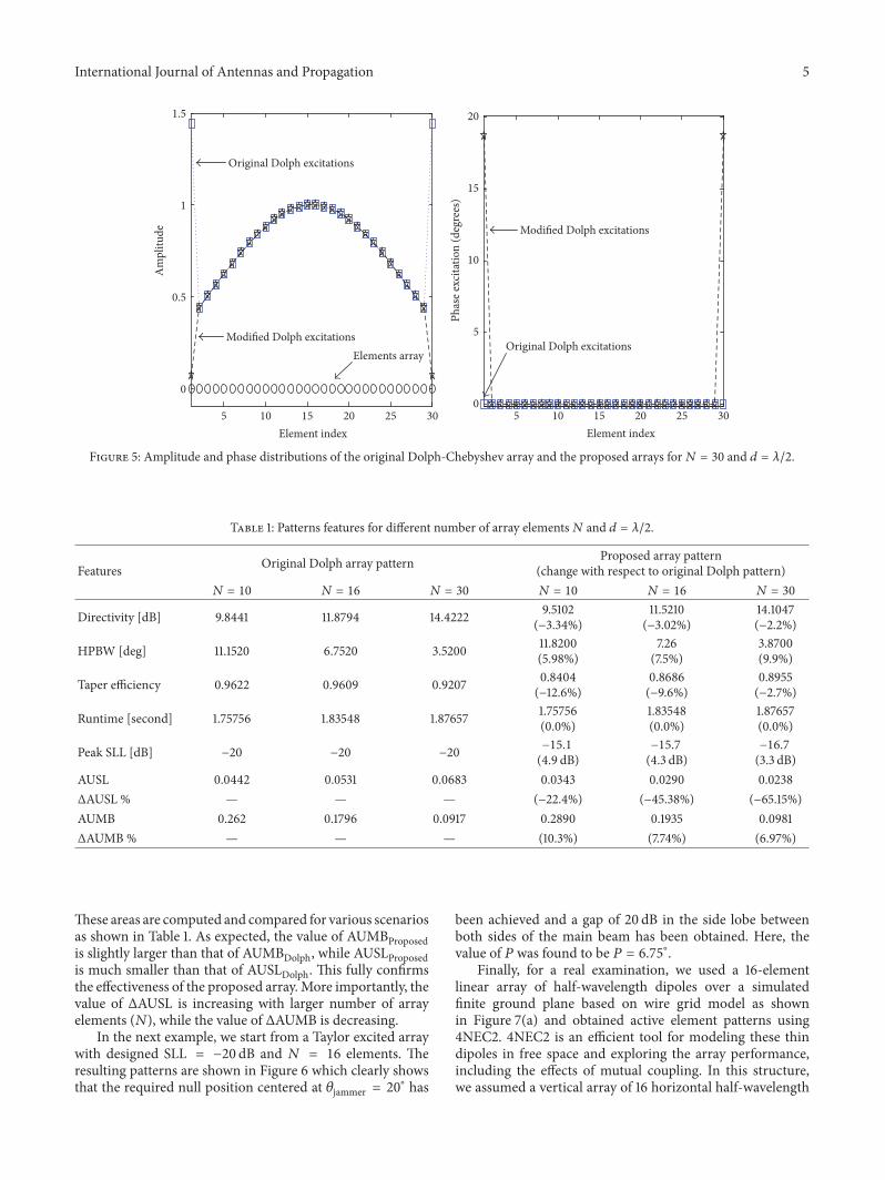
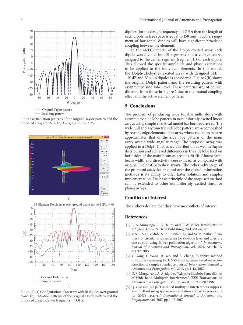