Embed Size (px)
Citation preview
System and Software Architecture Description (SSAD) Version 2.2
System and Software Architecture Description (SSAD)
Mobil Application for Mobile-Controlled Lighting
Team 13
Saumil Kasbekar Feasibility Analyst
Sayali Sakhalkar Software Architect
Anuradha Saini Life Cycle Planner
Priyank Mishra Project Manager
Sagar Sarda Requirements Engineer
Ashutosh Kale Prototyper
Corey Stall Requirements Engineer/Shaper
System and Software Architecture Description (SSAD) Version 2.2
SSAD_DCP_F14a_T13_V2.2.docx Version Date: 10/20/2014
ii
Version History Date Author Version Changes made Rationale
08/25/05 PA
2.0 Original template for use with
Instructional ICM-Sw v1.0
Initial draft for use with Instructional
ICM-Sw v1.0
05/25/09 SK 2.1 Embedded description in each table To be consistent with ICM EPG
template set standard V2.1
10/20/2014 PM 2.2 System and software architecture
description document which includes
system analysis, hardware and software
component description.
To comply with Instructional ICM-
Sw standard
System and Software Architecture Description (SSAD) Version 2.2
SSAD_DCP_F14a_T13_V2.2.docx Version Date: 10/20/2014 iii
Table of Contents
System and Software Architecture Description (SSAD) ............................................................ i Mobil Application for Mobile-Controlled Lighting .................................................................... i Version History ............................................................................................................................. ii
Table of Contents ......................................................................................................................... iii Table of Tables ............................................................................................................................. iv Table of Figures............................................................................................................................. v
1. Introduction ............................................................................................................................. 1
1.1 Purpose of the SSAD .................................................................................................... 1
1.2 Status of the SSAD ....................................................................................................... 1
2. System Analysis ....................................................................................................................... 2
2.1 System Analysis Overview ........................................................................................... 2
2.2 System Analysis Rationale ........................................................................................... 7
3. Technology-Independent Model ............................................................................................ 8
3.1 Design Overview ........................................................................................................... 8
3.2 Design Rationale ......................................................................................................... 13
4. Technology-Specific System Design .................................................................................... 15
4.1 Design Overview ......................................................................................................... 15
4.2 Design Rationale ......................................................................................................... 20
5. Architectural Styles, Patterns and Frameworks .................................................................. 21
System and Software Architecture Description (SSAD) Version 2.2
SSAD_DCP_F14a_T13_V2.2.docx iv Version Date: 10/20/2014
Table of Tables
Table 1: Actors Summary................................................................................................................ 2
Table 2: Artifacts and Information Summary ................................................................................. 3
Table 3: Process Description.......................................................................................................... 6
Table 4: Typical Course of Action .................................................................................................. 6
Table 5: Alternate Course of Action ............................................................................................... 6
Table 6: Exceptional Course of Action ........................................................................................... 6
Table 7: Hardware Component Description .................................................................................. 9
Table 8: Software Component Description..................................................................................... 9
Table 9: Supporting Software Component Description ................................................................ 10
Table 10: Design Class Description ............................................................................................. 12
Table 11: Hardware Component Description .............................................................................. 17
Table 12: Software Component Description................................................................................. 17
Table 13: Supporting Software Component Description .............................................................. 17
Table 14: Design Class Description ............................................................................................. 19
Table 15: Architectural Styles, Patterns, and Frameworks .......................................................... 21
System and Software Architecture Description (SSAD) Version no 2.2
SSAD_DCP_F14a_T13_V2.2.docx Version Date: 10/20/2014 v
Table of Figures
Figure 1: System Context Diagram ................................................................................................ 2
Figure 2: Artifacts and Information Diagram ................................................................................ 3
Figure 3: Process Diagram ............................................................................................................ 5
Figure 4: Hardware Component Class Diagram ........................................................................... 8
Figure 5: Software Component Class Diagram ............................................................................. 9
Figure 6: Deployment Diagram...................................................................................................... 9
Figure 7: Supporting Software Component Class Diagram........................................................... 9
Figure 8: Design Class Diagram .................................................................................................. 12
Figure 9: Process Realization Diagram ....................................................................................... 13
Figure 10: Hardware Component Class Diagram ....................................................................... 15
Figure 11: Software Component Class Diagram ......................................................................... 16
Figure 12: Deployment Diagram.................................................................................................. 16
Figure 13: Supporting Software Component Class Diagram....................................................... 17
Figure 14: Design Class Diagram ................................................................................................ 19
Figure 15: Process Realization Diagram ..................................................................................... 20
System and Software Architecture Description (SSAD) Version 2.2
SSAD_DCP_F14a_T13_V2.2.docx Version Date: 10/20/14 1
1. Introduction
1.1 Purpose of the SSAD
The objective of this document is to describe software architecture of the project and the
design decisions taken during the design process and the basis for each of them.
1.2 Status of the SSAD
This is the final draft of this document.
System and Software Architecture Description (SSAD) Version 2.2
SSAD_DCP_F14a_T13_V2.2.docx Version Date: 10/20/14 2
2. System Analysis
2.1 System Analysis Overview
The primary purpose of the Mobile-Controlled Lighting is making buildings switch free. This
system will help able users to control lights of their home and offices from mobile devices. User
can turn on or off the switch, all switches of the room, and all switches on one click. User can
group switches to room, floor. It will help to save electricity and also energy as we don’t have to
walk to switch to toggle it.
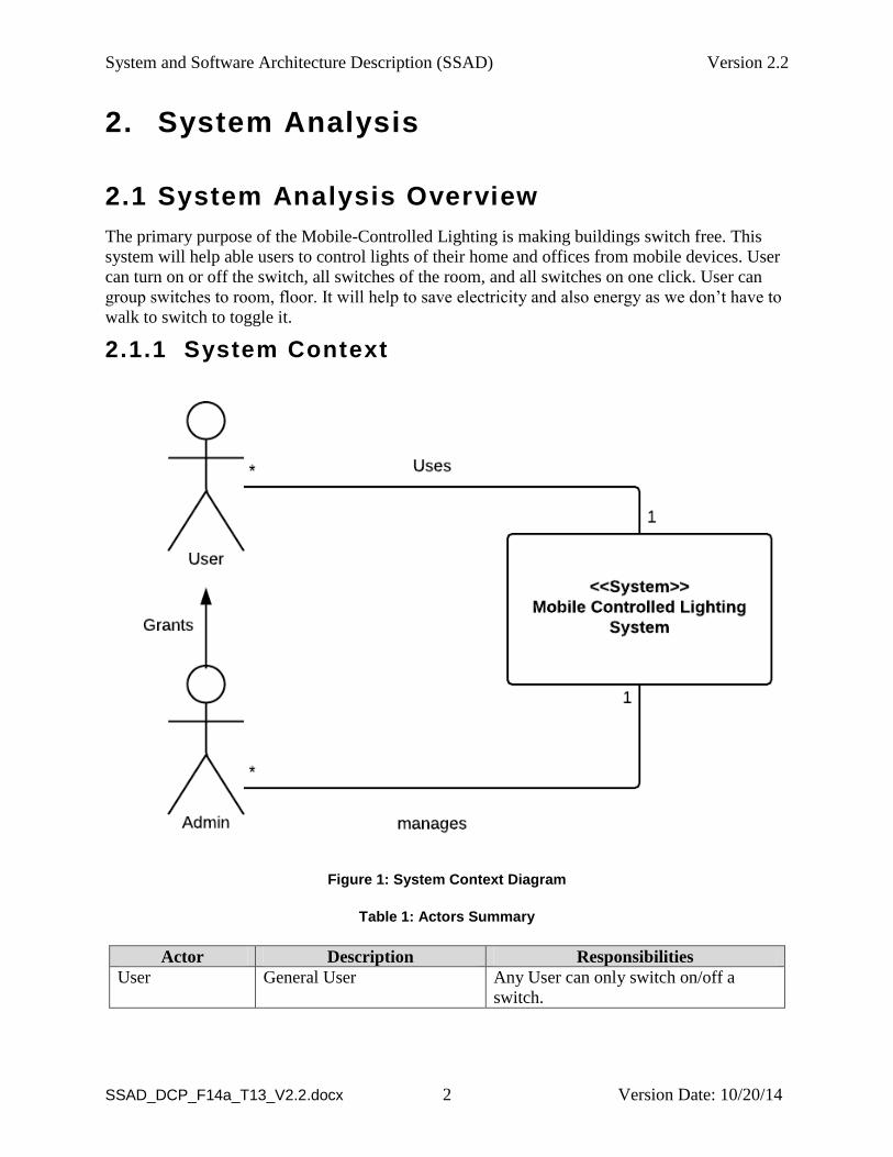
2.1.1 System Context
Figure 1: System Context Diagram
Table 1: Actors Summary
Actor Description Responsibilities
User General User Any User can only switch on/off a
switch.
System and Software Architecture Description (SSAD) Version 2.2
SSAD_DCP_F14a_T13_V2.2.docx Version Date: 10/20/14 3
Actor Description Responsibilities
Admin An admin who give access
permissions to other users
Add gateway, configure gateway, add
switch and provide access rights to
other users.
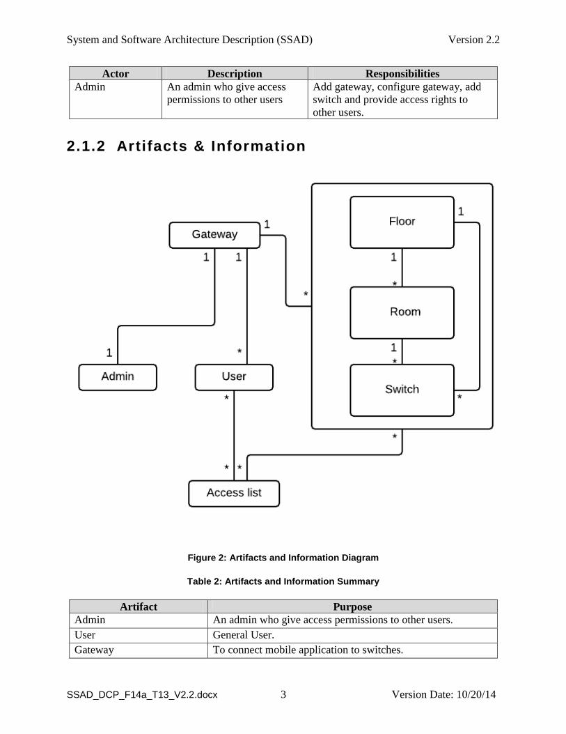
2.1.2 Artifacts & Information
Figure 2: Artifacts and Information Diagram
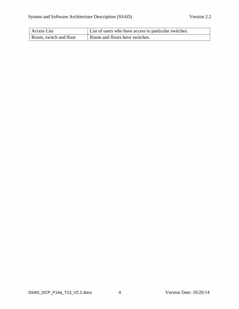
Table 2: Artifacts and Information Summary
Artifact Purpose
Admin An admin who give access permissions to other users.
User General User.
Gateway To connect mobile application to switches.
System and Software Architecture Description (SSAD) Version 2.2
SSAD_DCP_F14a_T13_V2.2.docx Version Date: 10/20/14 4
Access List List of users who have access to particular switches.
Room, switch and floor Room and floors have switches.
System and Software Architecture Description (SSAD) Version 2.2
SSAD_DCP_F14a_T13_V2.2.docx Version Date: 10/20/14 5
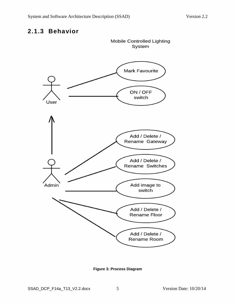
2.1.3 Behavior
Figure 3: Process Diagram
System and Software Architecture Description (SSAD) Version 2.2
SSAD_DCP_F14a_T13_V2.2.docx Version Date: 10/20/14 6
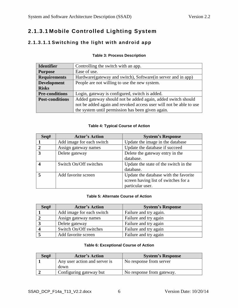
2.1.3.1 Mobile Controlled Lighting System
2.1.3 .1 .1 Switching the l ight w ith android app
Table 3: Process Description
Identifier Controlling the switch with an app.
Purpose Ease of use.
Requirements Hardware(gateway and switch), Software(in server and in app)
Development
Risks
People are not willing to use the new system.
Pre-conditions Login, gateway is configured, switch is added.
Post-conditions Added gateway should not be added again, added switch should
not be added again and revoked access user will not be able to use
the system until permission has been given again.
Table 4: Typical Course of Action
Seq# Actor’s Action System’s Response
1 Add image for each switch Update the image in the database
2 Assign gateway names Update the database if succeed
3 Delete gateway Delete the gateway entry in the
database.
4 Switch On/Off switches Update the state of the switch in the
database.
5 Add favorite screen Update the database with the favorite
screen having list of switches for a
particular user.
Table 5: Alternate Course of Action
Seq# Actor’s Action System’s Response
1 Add image for each switch Failure and try again.
2 Assign gateway names Failure and try again
3 Delete gateway Failure and try again
4 Switch On/Off switches Failure and try again
5 Add favorite screen Failure and try again
Table 6: Exceptional Course of Action
Seq# Actor’s Action System’s Response
1 Any user action and server is
down
No response from server
2 Configuring gateway but No response from gateway.
System and Software Architecture Description (SSAD) Version 2.2
SSAD_DCP_F14a_T13_V2.2.docx Version Date: 10/20/14 7
gateway is not configured
2.1.4 Modes of Operation
The system will operate in two modes:
1) Normal User Mode
2) Restricted User Mode
In Normal User Mode, anyone can access all the features in the app.
In Restricted User mode, user can lock manage gateway and manage switch screens. So
that only the authorized user can access those screens with password and no one else.
2.2 System Analysis Rationale
The rationale in system analysis is that the users are willing to use the mobile controlled
lighting and not the traditional switches. They are willing to add gateway, add switches and
give the access permissions to others for using them.
System and Software Architecture Description (SSAD) Version 2.2
SSAD_DCP_F14a_T13_V2.2.docx Version Date: 10/20/14 8
3. Technology-Independent Model
3.1 Design Overview
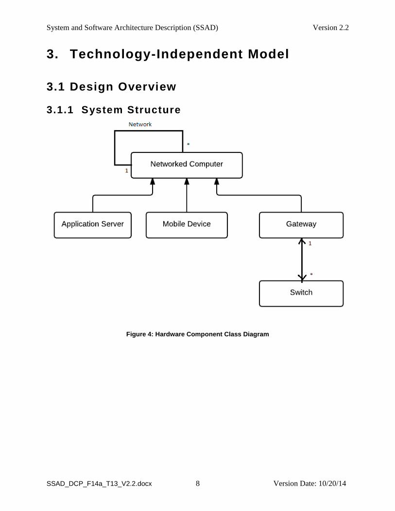
3.1.1 System Structure
Figure 4: Hardware Component Class Diagram
System and Software Architecture Description (SSAD) Version 2.2
SSAD_DCP_F14a_T13_V2.2.docx Version Date: 10/20/14 9
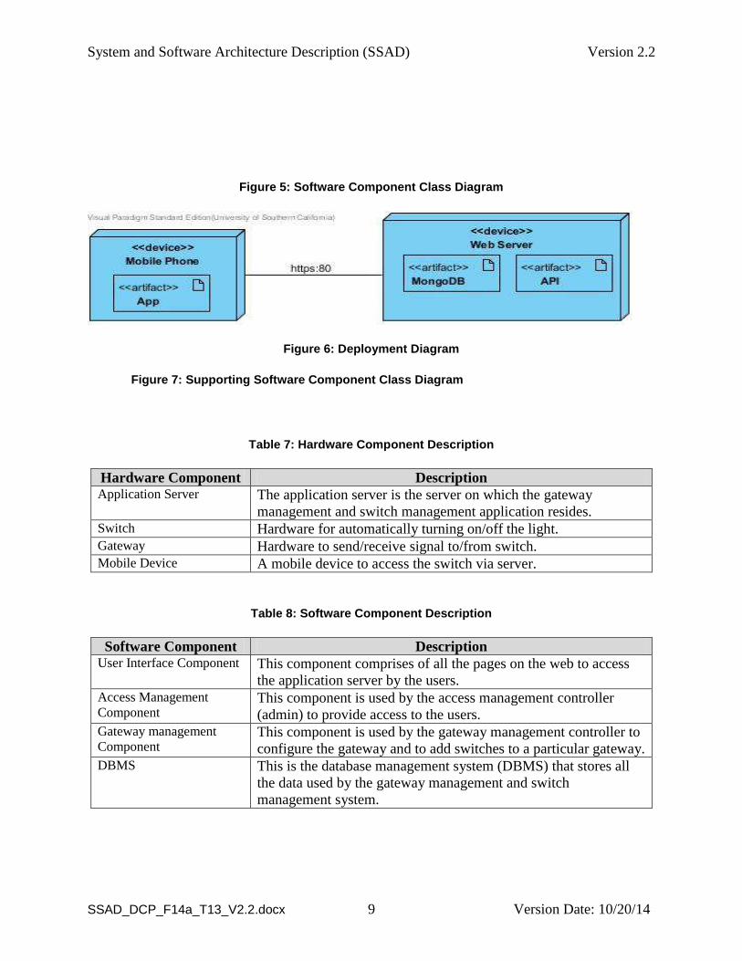
Figure 5: Software Component Class Diagram
Figure 6: Deployment Diagram
Figure 7: Supporting Software Component Class Diagram
Table 7: Hardware Component Description
Hardware Component Description Application Server The application server is the server on which the gateway
management and switch management application resides. Switch Hardware for automatically turning on/off the light. Gateway Hardware to send/receive signal to/from switch. Mobile Device A mobile device to access the switch via server.
Table 8: Software Component Description
Software Component Description User Interface Component This component comprises of all the pages on the web to access
the application server by the users. Access Management
Component This component is used by the access management controller
(admin) to provide access to the users. Gateway management
Component This component is used by the gateway management controller to
configure the gateway and to add switches to a particular gateway. DBMS This is the database management system (DBMS) that stores all
the data used by the gateway management and switch
management system.
System and Software Architecture Description (SSAD) Version 2.2
SSAD_DCP_F14a_T13_V2.2.docx Version Date: 10/20/14 10
Table 9: Supporting Software Component Description
Support Software Component Description
System and Software Architecture Description (SSAD) Version 2.2
SSAD_DCP_F14a_T13_V2.2.docx Version Date: 10/20/14 11
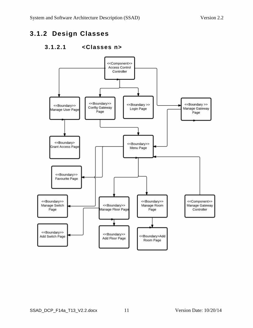
3.1.2 Design Classes
3.1.2.1 <Classes n>
System and Software Architecture Description (SSAD) Version 2.2
SSAD_DCP_F14a_T13_V2.2.docx Version Date: 10/20/14 12
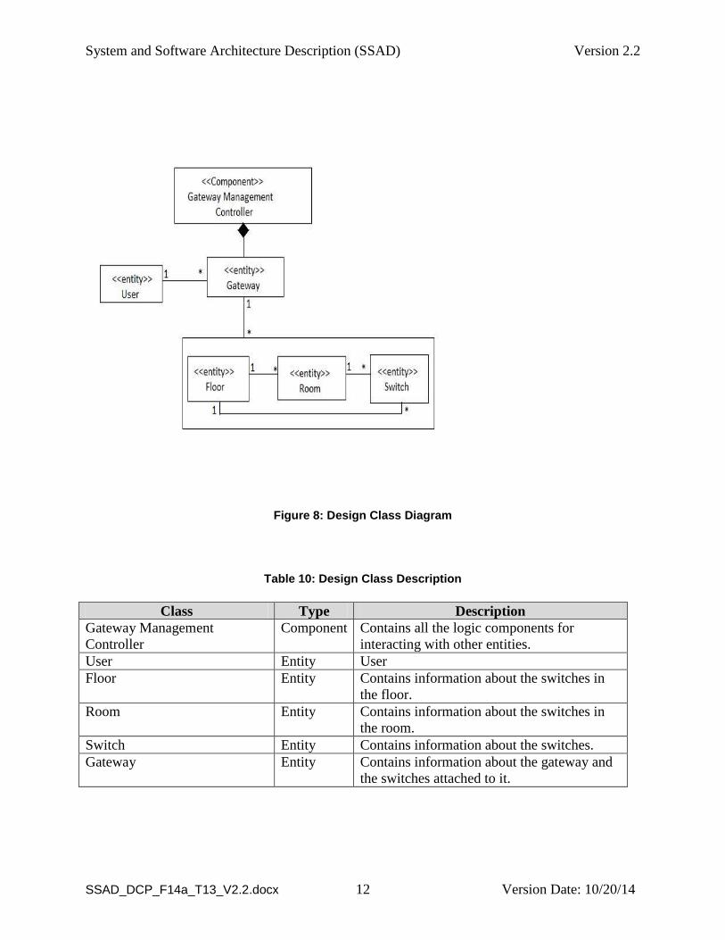
Figure 8: Design Class Diagram
Table 10: Design Class Description
Class Type Description
Gateway Management
Controller
Component Contains all the logic components for
interacting with other entities.
User Entity User
Floor Entity Contains information about the switches in
the floor.
Room Entity Contains information about the switches in
the room.
Switch Entity Contains information about the switches.
Gateway Entity Contains information about the gateway and
the switches attached to it.
System and Software Architecture Description (SSAD) Version 2.2
SSAD_DCP_F14a_T13_V2.2.docx Version Date: 10/20/14 13
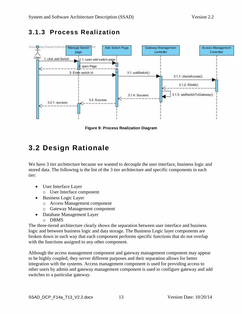
3.1.3 Process Realization
Figure 9: Process Realization Diagram
3.2 Design Rationale
We have 3 tier architecture because we wanted to decouple the user interface, business logic and
stored data. The following is the list of the 3 tier architecture and specific components in each
tier:
User Interface Layer
o User Interface component
Business Logic Layer
o Access Management component
o Gateway Management component
Database Management Layer
o DBMS
The three-tiered architecture clearly shows the separation between user interface and business
logic and between business logic and data storage. The Business Logic layer components are
broken down in such way that each component performs specific functions that do not overlap
with the functions assigned to any other component.
Although the access management component and gateway management component may appear
to be highly coupled, they server different purposes and their separation allows for better
integration with the systems. Access management component is used for providing access to
other users by admin and gateway management component is used to configure gateway and add
switches to a particular gateway.
System and Software Architecture Description (SSAD) Version 2.2
SSAD_DCP_F14a_T13_V2.2.docx Version Date: 10/20/14 14
We decided to use a COTS DBMS because it would be too time consuming to implement the
data storage component through the hardware platform's file system.
System and Software Architecture Description (SSAD) Version 2.2
SSAD_DCP_F14a_T13_V2.2.docx Version Date: 10/20/14 15
4. Technology-Specific System Design
4.1 Design Overview
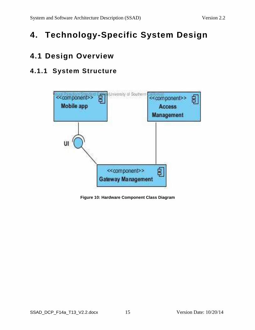
4.1.1 System Structure
Figure 10: Hardware Component Class Diagram
System and Software Architecture Description (SSAD) Version 2.2
SSAD_DCP_F14a_T13_V2.2.docx Version Date: 10/20/14 16
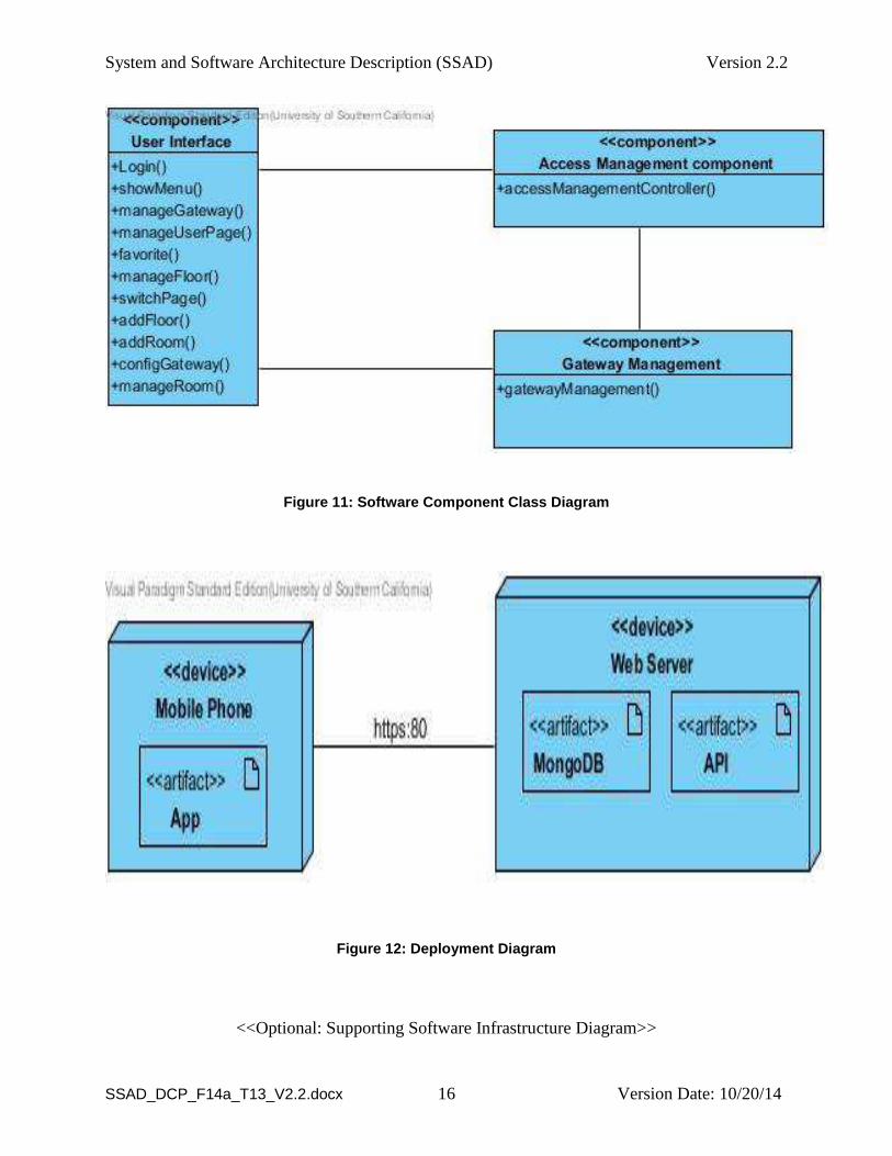
Figure 11: Software Component Class Diagram
Figure 12: Deployment Diagram
<<Optional: Supporting Software Infrastructure Diagram>>
System and Software Architecture Description (SSAD) Version 2.2
SSAD_DCP_F14a_T13_V2.2.docx Version Date: 10/20/14 17
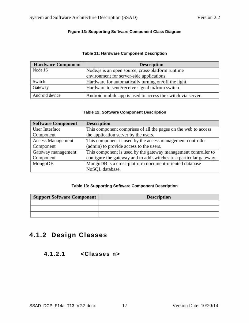
Figure 13: Supporting Software Component Class Diagram
Table 11: Hardware Component Description
Hardware Component Description Node JS Node.js is an open source, cross-platform runtime
environment for server-side applications Switch Hardware for automatically turning on/off the light. Gateway Hardware to send/receive signal to/from switch.
Android device Android mobile app is used to access the switch via server.
Table 12: Software Component Description
Software Component Description
User Interface
Component
This component comprises of all the pages on the web to access
the application server by the users.
Access Management
Component
This component is used by the access management controller
(admin) to provide access to the users.
Gateway management
Component
This component is used by the gateway management controller to
configure the gateway and to add switches to a particular gateway.
MongoDB MongoDB is a cross-platform document-oriented database
NoSQL database.
Table 13: Supporting Software Component Description
Support Software Component Description
4.1.2 Design Classes
4.1.2.1 <Classes n>
System and Software Architecture Description (SSAD) Version 2.2
SSAD_DCP_F14a_T13_V2.2.docx Version Date: 10/20/14 18
System and Software Architecture Description (SSAD) Version 2.2
SSAD_DCP_F14a_T13_V2.2.docx Version Date: 10/20/14 19
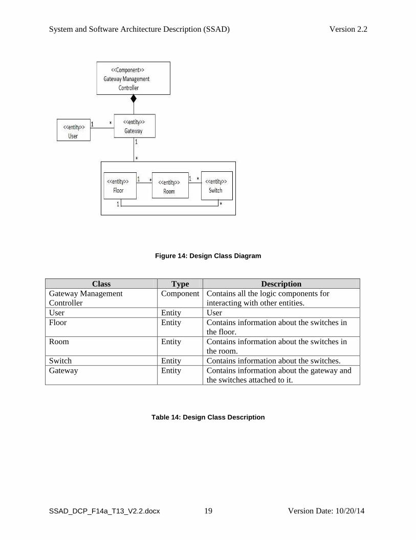
Figure 14: Design Class Diagram
Class Type Description
Gateway Management
Controller
Component Contains all the logic components for
interacting with other entities.
User Entity User
Floor Entity Contains information about the switches in
the floor.
Room Entity Contains information about the switches in
the room.
Switch Entity Contains information about the switches.
Gateway Entity Contains information about the gateway and
the switches attached to it.
Table 14: Design Class Description
System and Software Architecture Description (SSAD) Version 2.2
SSAD_DCP_F14a_T13_V2.2.docx Version Date: 10/20/14 20
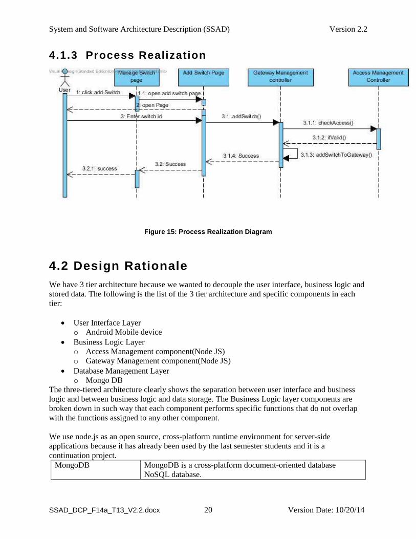
4.1.3 Process Realization
Figure 15: Process Realization Diagram
4.2 Design Rationale
We have 3 tier architecture because we wanted to decouple the user interface, business logic and
stored data. The following is the list of the 3 tier architecture and specific components in each
tier:
User Interface Layer
o Android Mobile device
Business Logic Layer
o Access Management component(Node JS)
o Gateway Management component(Node JS)
Database Management Layer
o Mongo DB
The three-tiered architecture clearly shows the separation between user interface and business
logic and between business logic and data storage. The Business Logic layer components are
broken down in such way that each component performs specific functions that do not overlap
with the functions assigned to any other component.
We use node.js as an open source, cross-platform runtime environment for server-side
applications because it has already been used by the last semester students and it is a
continuation project.
MongoDB MongoDB is a cross-platform document-oriented database
NoSQL database.
System and Software Architecture Description (SSAD) Version 2.2
SSAD_DCP_F14a_T13_V2.2.docx Version Date: 10/20/14 21
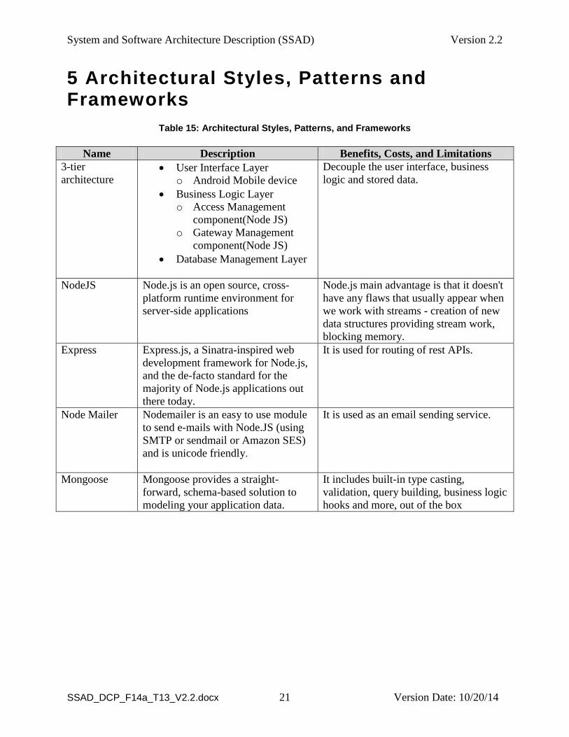
5 Architectural Styles, Patterns and Frameworks
Table 15: Architectural Styles, Patterns, and Frameworks
Name Description Benefits, Costs, and Limitations
3-tier
architecture User Interface Layer
o Android Mobile device
Business Logic Layer
o Access Management
component(Node JS)
o Gateway Management
component(Node JS)
Database Management Layer
Decouple the user interface, business
logic and stored data.
NodeJS Node.js is an open source, cross-
platform runtime environment for
server-side applications
Node.js main advantage is that it doesn't
have any flaws that usually appear when
we work with streams - creation of new
data structures providing stream work,
blocking memory.
Express Express.js, a Sinatra-inspired web
development framework for Node.js,
and the de-facto standard for the
majority of Node.js applications out
there today.
It is used for routing of rest APIs.
Node Mailer Nodemailer is an easy to use module
to send e-mails with Node.JS (using
SMTP or sendmail or Amazon SES)
and is unicode friendly.
It is used as an email sending service.
Mongoose Mongoose provides a straight-
forward, schema-based solution to
modeling your application data.
It includes built-in type casting,
validation, query building, business logic
hooks and more, out of the box