Embed Size (px)
Citation preview
System Architecture and Cross-Layer Optimization of Video Broadcast over WiMAX
CMPT 820Bob McAuliffeJuly 24, 2008
2
Reference
System Architecture and Cross-Layer Optimization of Video Broadcast over WiMAX
Jianfeng Wang, Muthaiah Venkatachalam, and Yuguang Fang
3
Outline
Introduction Overview of WiMAX MBS and issues
MBS -> multicast / broadcast service Proposed end-to-end solution Optimization methodology Results Conclusions
4
Introduction
Mobile WiMAX (802.16e) operation Wireless mobile TV WiMAX defines only MAC/PHY of wireless link
Broadcast TV requires multi-BS operation Synchronization issues
Current MBS to BS (base stations)
transport protocol - RTP / UDP / IP
5
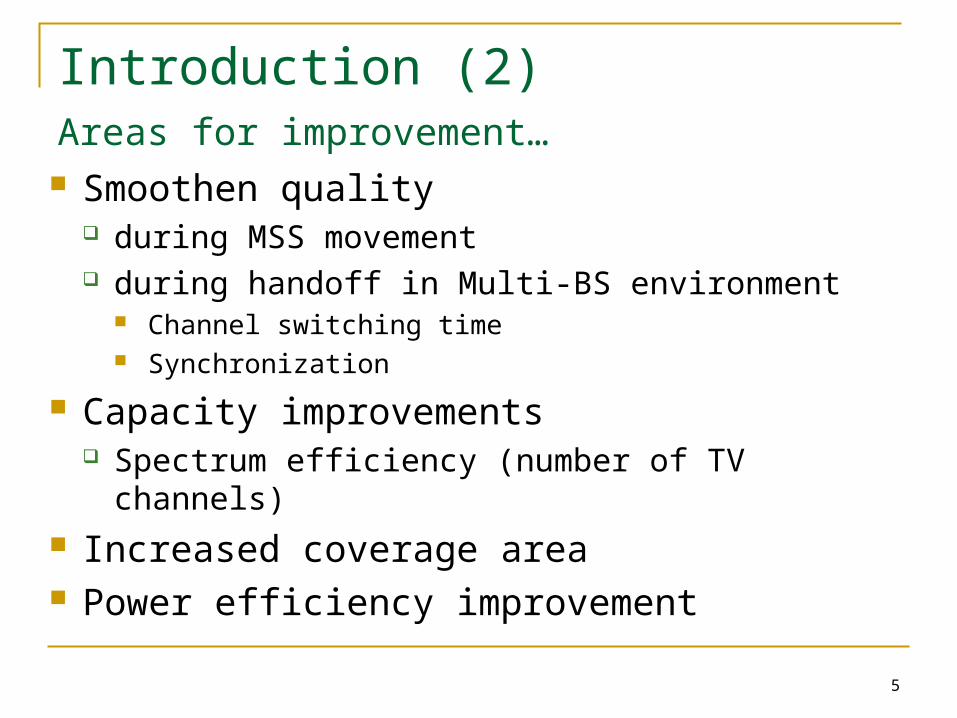
Introduction (2)Areas for improvement… Smoothen quality
during MSS movement during handoff in Multi-BS environment
Channel switching time Synchronization
Capacity improvements Spectrum efficiency (number of TV channels)
Increased coverage area Power efficiency improvement
6
Introduction (3)Viable end-to-end solution proposed From MBS Controller Through BS To MSS (mobile subscriber stations)
Overview of WiMAX MBS and issues
8
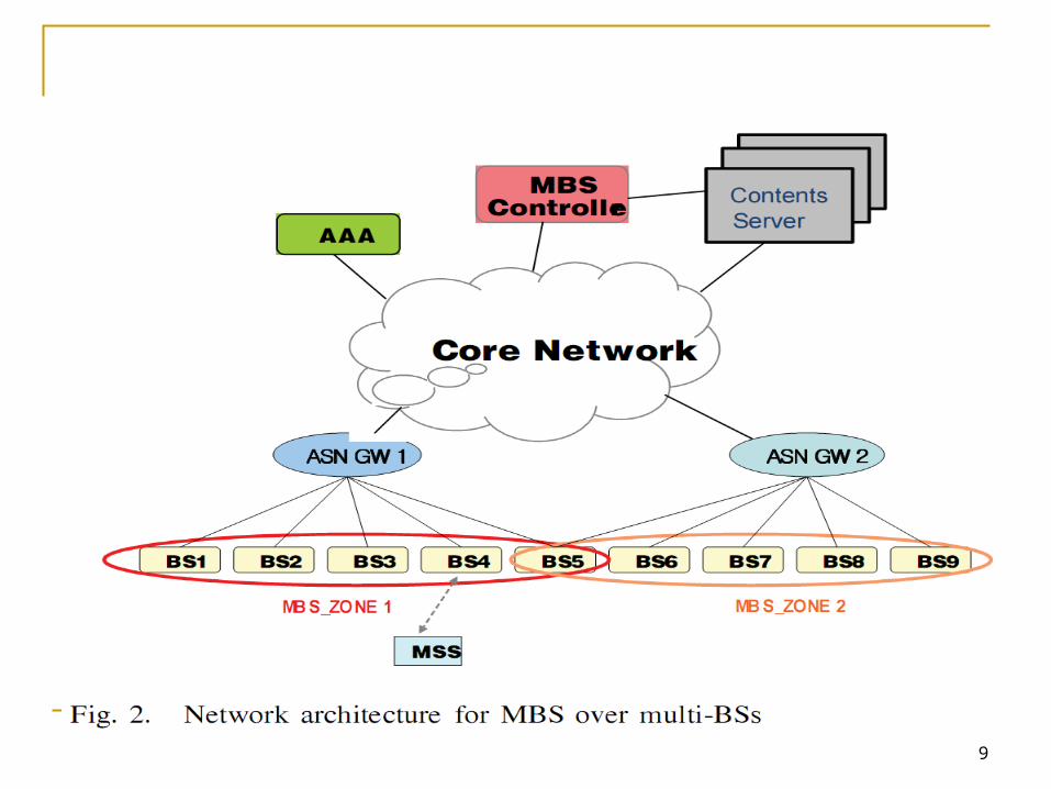
Overview of WiMAX / MBS
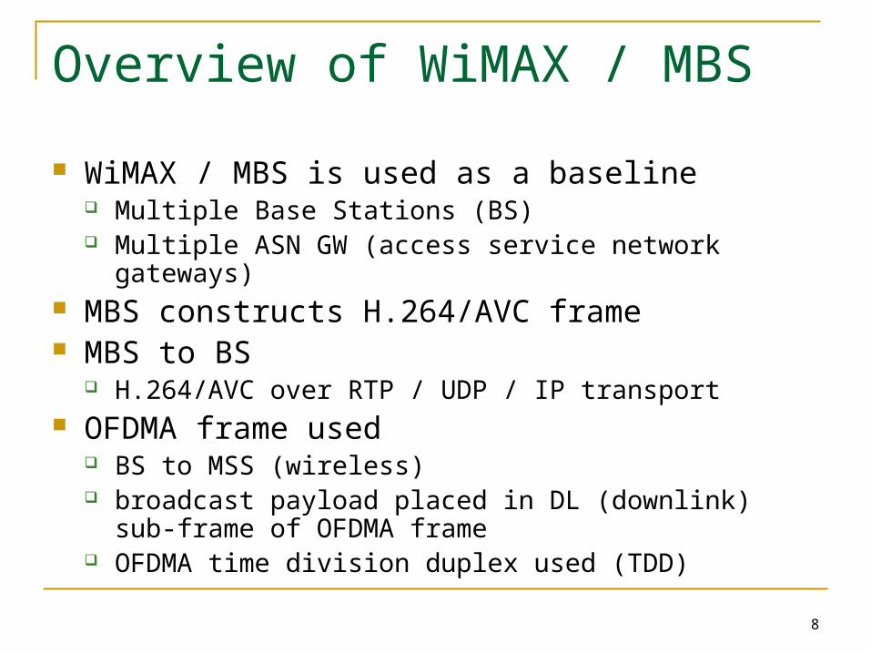
WiMAX / MBS is used as a baseline Multiple Base Stations (BS) Multiple ASN GW (access service network gateways)
MBS constructs H.264/AVC frame MBS to BS
H.264/AVC over RTP / UDP / IP transport OFDMA frame used
BS to MSS (wireless) broadcast payload placed in DL (downlink) sub-frame of
OFDMA frame OFDMA time division duplex used (TDD)
9
10
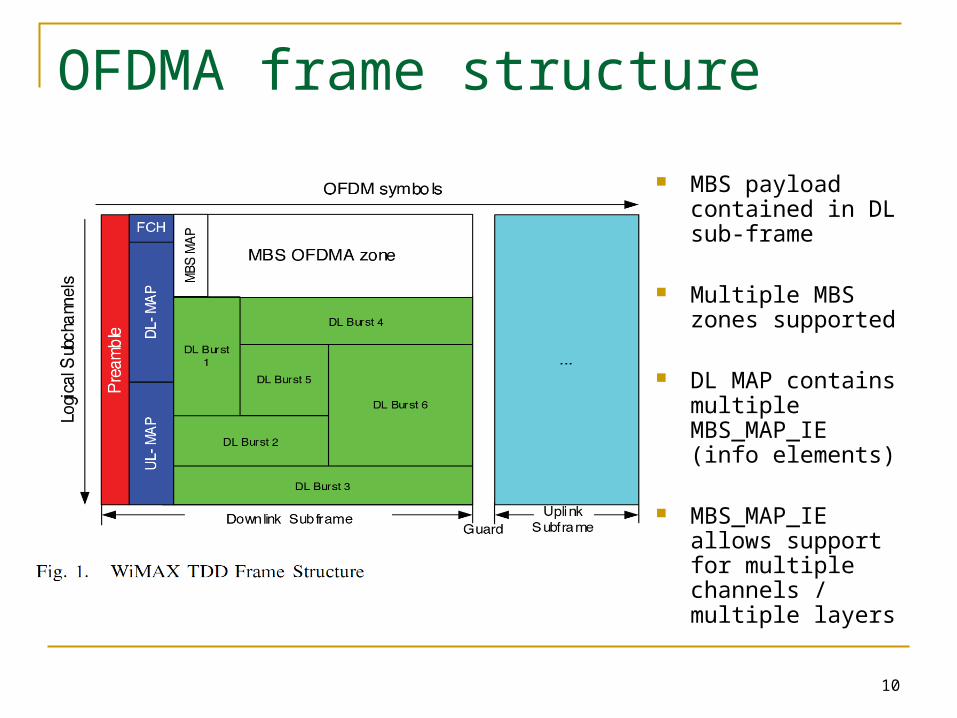
OFDMA frame structure
MBS payload contained in DL sub-frame
Multiple MBS zones supported
DL MAP contains multiple MBS_MAP_IE (info elements)
MBS_MAP_IE allows support for multiple channels / multiple layers
11
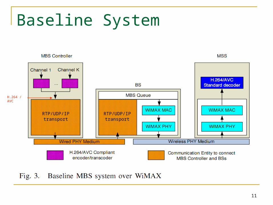
Baseline System
H.264 / AVC
RTP/UDP/IP
transportRTP/UDP/IP
transport
12
MSS operation (baseline)
MSS reads DL-MAP to determine; MBS MAPS MBS Zones MBS MAPS point to subsequent MBS MAPS
13
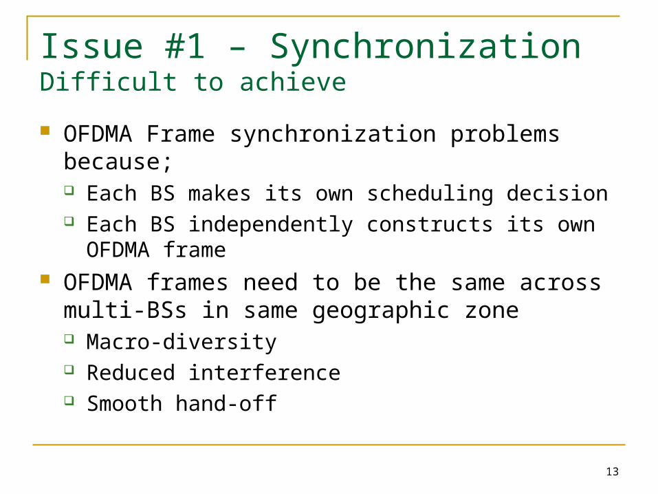
Issue #1 – SynchronizationDifficult to achieve
OFDMA Frame synchronization problems because; Each BS makes its own scheduling decision Each BS independently constructs its own OFDMA
frame OFDMA frames need to be the same across multi-
BSs in same geographic zone Macro-diversity Reduced interference Smooth hand-off
14
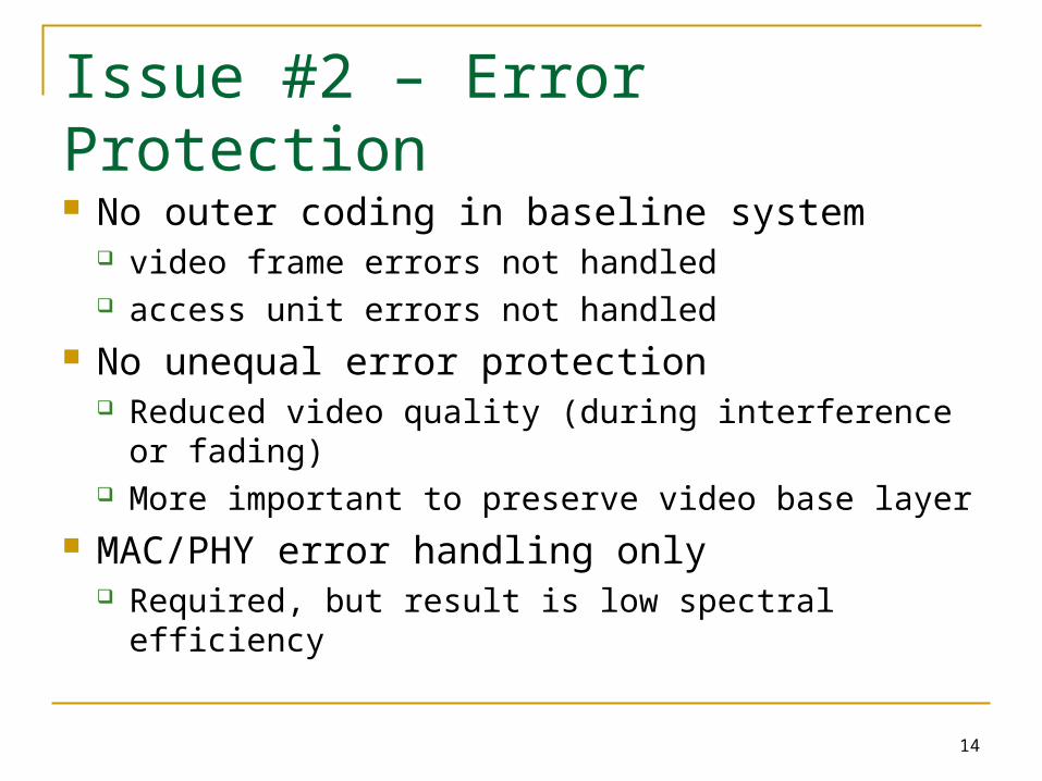
Issue #2 – Error Protection
No outer coding in baseline system video frame errors not handled access unit errors not handled
No unequal error protection Reduced video quality (during interference or
fading) More important to preserve video base layer
MAC/PHY error handling only Required, but result is low spectral efficiency
15
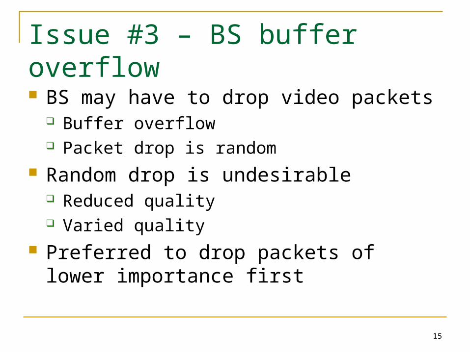
Issue #3 – BS buffer overflow
BS may have to drop video packets Buffer overflow Packet drop is random
Random drop is undesirable Reduced quality Varied quality
Preferred to drop packets of lower importance first
16
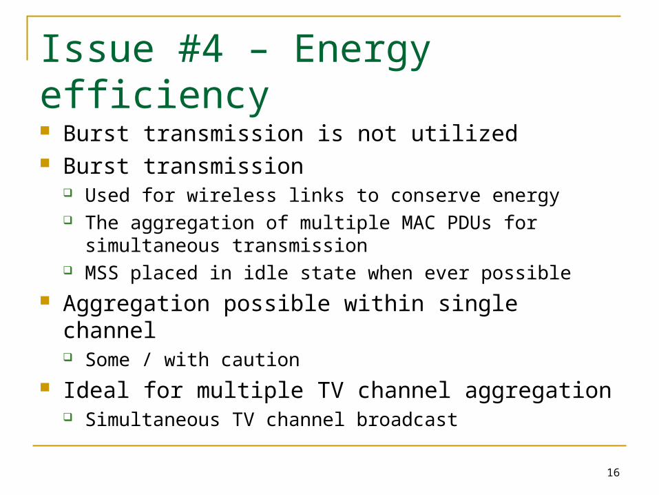
Issue #4 – Energy efficiency
Burst transmission is not utilized Burst transmission
Used for wireless links to conserve energy The aggregation of multiple MAC PDUs for simultaneous
transmission MSS placed in idle state when ever possible
Aggregation possible within single channel Some / with caution
Ideal for multiple TV channel aggregation Simultaneous TV channel broadcast

17
Issue #5 – Packet overhead
Significant packet overhead between MBS and BS RTP, UDP, IP Approximately 40 bytes per packet Header compression
Significant RTP/UDP/IP header reduction is possible
Proposed end-to-end solution
19
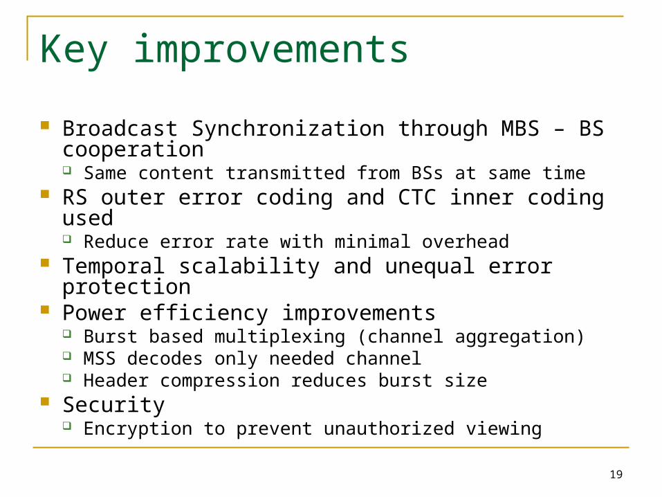
Key improvements
Broadcast Synchronization through MBS – BS cooperation Same content transmitted from BSs at same time
RS outer error coding and CTC inner coding used Reduce error rate with minimal overhead
Temporal scalability and unequal error protection Power efficiency improvements
Burst based multiplexing (channel aggregation) MSS decodes only needed channel Header compression reduces burst size
Security Encryption to prevent unauthorized viewing
20
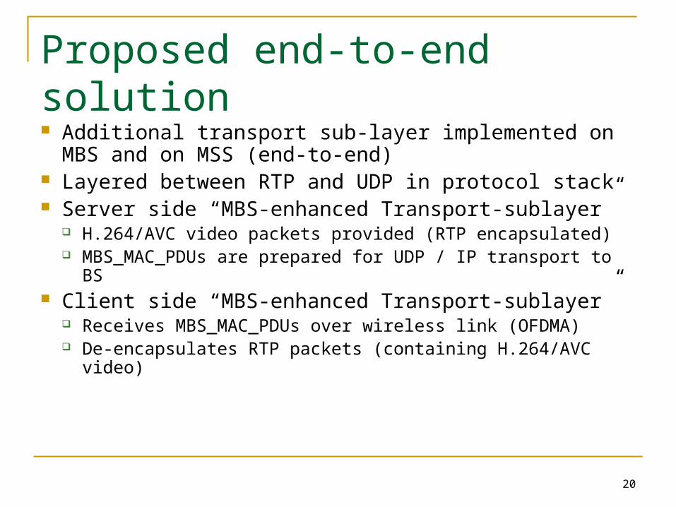
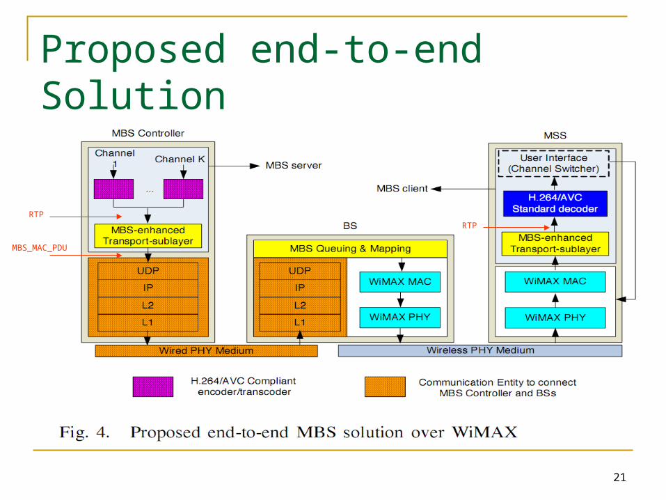
Proposed end-to-end solution
Additional transport sub-layer implemented on MBS and on MSS (end-to-end)
Layered between RTP and UDP in protocol stack Server side “MBS-enhanced Transport-sublayer”
H.264/AVC video packets provided (RTP encapsulated) MBS_MAC_PDUs are prepared for UDP / IP transport to
BS Client side “MBS-enhanced Transport-sublayer”
Receives MBS_MAC_PDUs over wireless link (OFDMA) De-encapsulates RTP packets (containing H.264/AVC
video)
21
Proposed end-to-end Solution
RTP
MBS_MAC_PDU
RTP
22
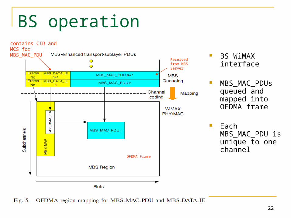
BS operation
BS WiMAX interface
MBS_MAC_PDUs queued and mapped into OFDMA frame
Each MBS_MAC_PDU is unique to one channel
Received from MBS Server
OFDMA Frame
contains CID and MCS for MBS_MAC_PDU
23
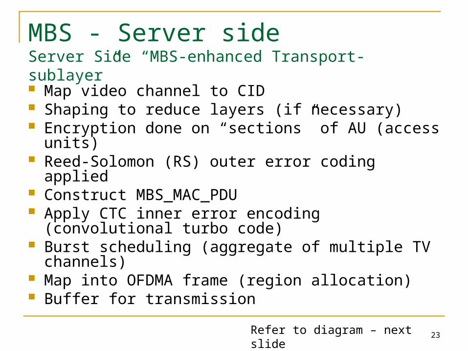
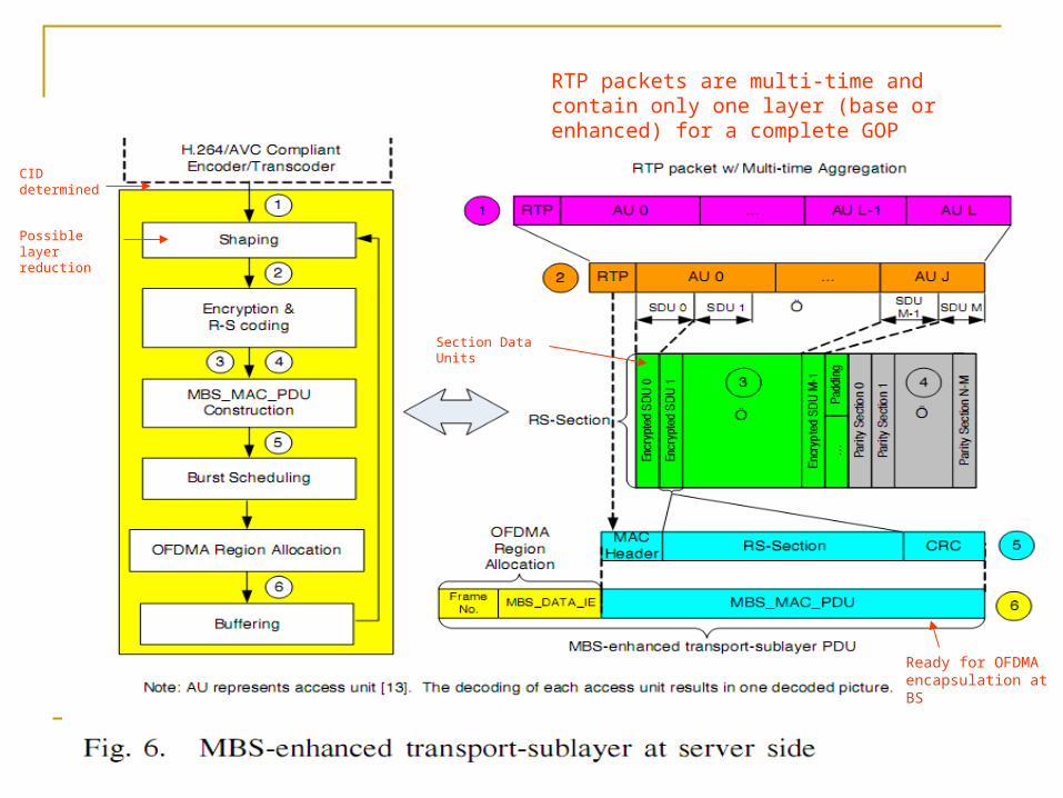
MBS - Server sideServer Side “MBS-enhanced Transport-sublayer”
Map video channel to CID Shaping to reduce layers (if necessary) Encryption done on “sections” of AU (access units) Reed-Solomon (RS) outer error coding applied Construct MBS_MAC_PDU Apply CTC inner error encoding (convolutional turbo
code) Burst scheduling (aggregate of multiple TV
channels) Map into OFDMA frame (region allocation) Buffer for transmission
Refer to diagram – next slide
24
Possible layer reduction
CID determined
Section Data Units
Ready for OFDMA encapsulation at BS
RTP packets are multi-time and contain only one layer (base or enhanced) for a complete GOP
25
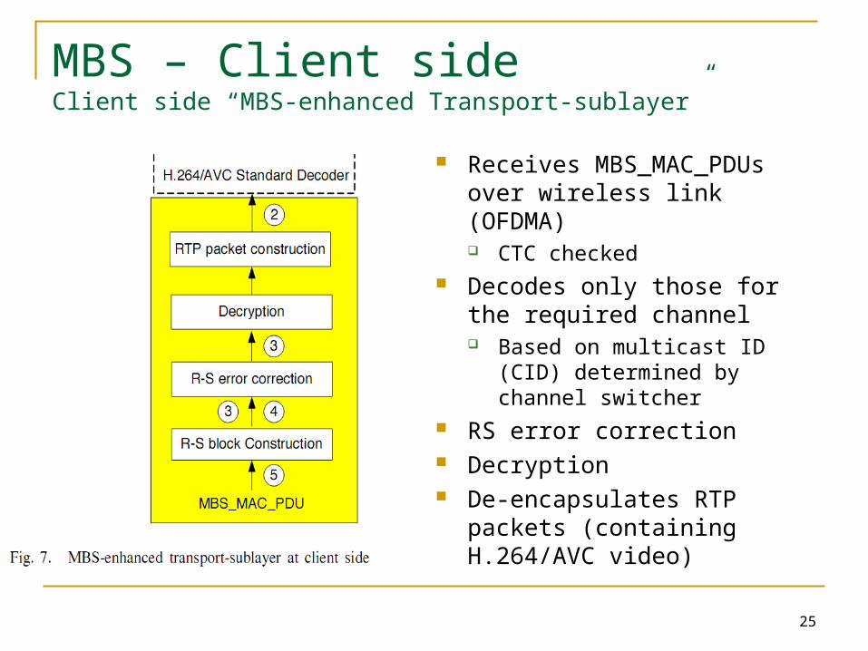
MBS – Client sideClient side “MBS-enhanced Transport-sublayer”
Receives MBS_MAC_PDUs over wireless link (OFDMA) CTC checked
Decodes only those for the required channel Based on multicast ID (CID)
determined by channel switcher RS error correction Decryption De-encapsulates RTP packets
(containing H.264/AVC video)

26
Burst scheduling Energy efficiency
improvement Round-robin channel to
channel Determined at MBS server A burst contains many/all
channels and multiple MBS_MAC_PDUs per channel
Burst size chosen to ensure max efficiency and reasonable switch delay between channels
MBS client set to idle mode between bursts
One Burst
27
Channel switching (MBS client) Improved energy efficiency MBS client operation
determines desired CID Looks in MBS MAP of received OFDMA frame (via WiMAX) Locates MBS_DATA_IEs for new CID Begins decoding corresponding MBS_MAC_PDUs for new
CID Stops decoding previous MBS_MAC_PDUs
Power not wasted decoding MBS_MAC_PDUs not associated with channel being viewed
28
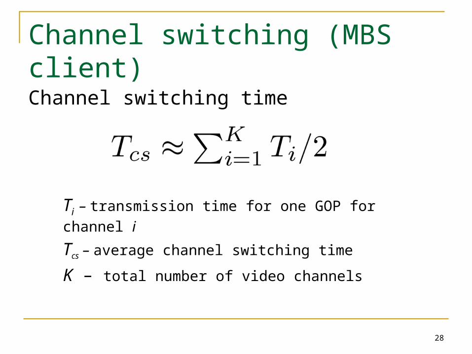
Channel switching (MBS client)Channel switching time
Ti – transmission time for one GOP for channel i
Tcs – average channel switching time
K – total number of video channels
29
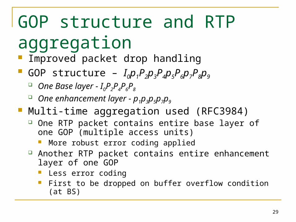
GOP structure and RTP aggregation Improved packet drop handling GOP structure – I0p1P2p3P4p5P6p7P8p9
One Base layer - I0P2P4P6P8
One enhancement layer - p1p3p5p7p9
Multi-time aggregation used (RFC3984) One RTP packet contains entire base layer of one GOP
(multiple access units) More robust error coding applied
Another RTP packet contains entire enhancement layer of one GOP Less error coding First to be dropped on buffer overflow condition (at BS)
30
RS coding / decoding
Reed-Solomon (RS) error coding Robust error recovery RS outer coding applied to each RTP packet
RTP packet fragmented into M “sections” (SDUs) N-M Parity “sections” appended (parity SDUs)
Where N is the total number of RS sections More robust FEC (larger N) applied to base layer RTP
packets Unequal error protection
CRC applied to each SDU and parity SDU Efficient for MBS client to detect SDU errors
31
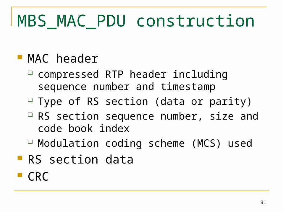
MBS_MAC_PDU construction
MAC header compressed RTP header including sequence
number and timestamp Type of RS section (data or parity) RS section sequence number, size and code
book index Modulation coding scheme (MCS) used
RS section data CRC
32
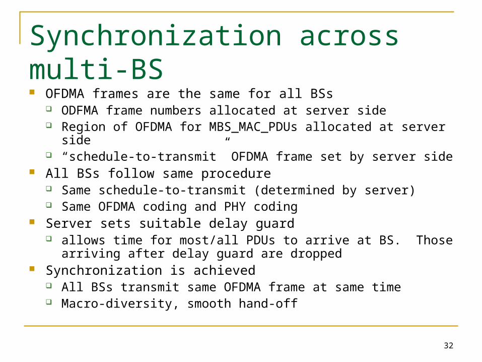
Synchronization across multi-BS OFDMA frames are the same for all BSs
ODFMA frame numbers allocated at server side Region of OFDMA for MBS_MAC_PDUs allocated at server side “schedule-to-transmit” OFDMA frame set by server side
All BSs follow same procedure Same schedule-to-transmit (determined by server) Same OFDMA coding and PHY coding
Server sets suitable delay guard allows time for most/all PDUs to arrive at BS. Those arriving
after delay guard are dropped Synchronization is achieved
All BSs transmit same OFDMA frame at same time Macro-diversity, smooth hand-off
33
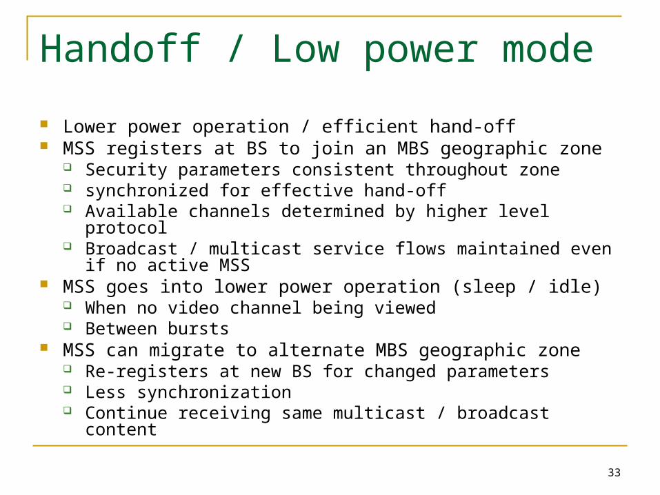
Handoff / Low power mode
Lower power operation / efficient hand-off MSS registers at BS to join an MBS geographic zone
Security parameters consistent throughout zone synchronized for effective hand-off Available channels determined by higher level protocol Broadcast / multicast service flows maintained even if no active
MSS MSS goes into lower power operation (sleep / idle)
When no video channel being viewed Between bursts
MSS can migrate to alternate MBS geographic zone Re-registers at new BS for changed parameters Less synchronization Continue receiving same multicast / broadcast content
Optimization methodology
35
Optimization approach
Goal: to balance the following characteristics: Video Quality
Represented by effective frame rate (EFR) Spectral efficiency
Measured as number of channels supported Coverage
Distance (size of the cell)
36
Video Quality
Use EFR (effective frame rate) as a measure of quality The rate of correct frame decoding at the application
Factors influencing EFR (quality) Distance (d) Speed (s) RS section size (L) - base and enhancement layers RS coding rate (p) - base and enhancement layers MCS (modulation coding scheme) for base and enhancement
layers CTC inner coding scheme Base layer frame rate – fb
Enhancement layer frame rate – fe
37
Optimization (quality vs capacity) Optimization (quality vs spectral efficiency)
Determine minimum EFR requirement (i.e. base layer only) - at cell edge (EFRmin)
Determine maximum K (channels), while maintaining EFRmin

Results
39
Test Environment
Fixed parameters RF environment
carrier 2.5GHz, BW 10 MHz, etc (Ref: table III) OFDMA slot rate set at 144 kps H.264/AVC – QVGA 240*320, 30 fps GOP structure – IpPpPpPpPp Robust error encoding for MAP_DATA_IE so that
error probability is negligible
40
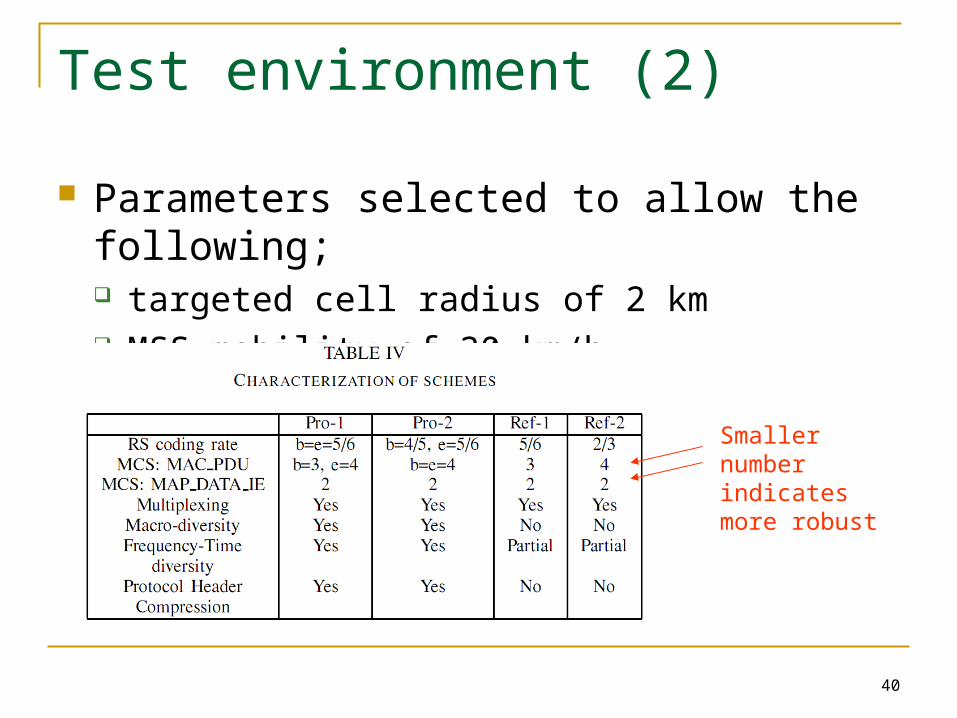
Test environment (2)
Parameters selected to allow the following; targeted cell radius of 2 km MSS mobility of 30 km/h
Smaller number indicates more robust
41
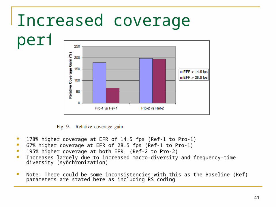
Increased coverage performance
178% higher coverage at EFR of 14.5 fps (Ref-1 to Pro-1) 67% higher coverage at EFR of 28.5 fps (Ref-1 to Pro-1) 195% higher coverage at both EFR (Ref-2 to Pro-2) Increases largely due to increased macro-diversity and frequency-time diversity (synchronization)
Note: There could be some inconsistencies with this as the Baseline (Ref) parameters are stated here as including RS coding
42
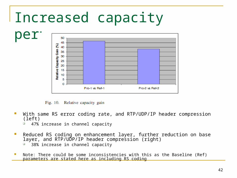
Increased capacity performance
With same RS error coding rate, and RTP/UDP/IP header compression (left) 47% increase in channel capacity
Reduced RS coding on enhancement layer, further reduction on base layer, and RTP/UDP/IP header compression (right) 38% increase in channel capacity
Note: There could be some inconsistencies with this as the Baseline (Ref) parameters are stated here as including RS coding

Conclusions
44
Conclusions
End-to-end solution provides increased macro-diversity improved synchronization, therefore improved coverage
and capacity Improved hand-off
Improved error coding (2 levels) to reduce error rate while minimizing frame overhead
Temporal scalability and unequal error protection Provides smoother quality degradation Therefore greater effective range /capacity
Energy efficiency improvement Burst based Increased MSS idle mode

45
Questions ?

46
End


![⃝[mary s mcauliffe (editor)] cia documents](https://img.pdfslide.net/doc/110x75/568caa281a28ab186da072ef/mary-s-mcauliffe-editor-cia-documents.jpg)