Embed Size (px)
Citation preview

Proceedings of Space Nuclear Conference 2007 Boston, Massachusetts, June 24-28 2007
Paper 2049
System Modeling of Lunar Oxygen Production: Mass and Power Requirements
Christopher J. Steffen, Jr., Joshua E. Freeh, Diane L. Linne, Eric W. Faykus, Christopher A. Gallo, and Robert D. Green NASA Glenn Research Center at Lewis Field
21000 Brookpark Road, Cleveland, Ohio 44135 216.433.8508, 216.433.5802, [email protected]
Abstract – A systems analysis tool for estimating the mass and power requirements for a lunar oxygen production facility is introduced. The individual modeling components involve the chemical processing and cryogenic storage subsystems needed to process a beneficiated regolith stream into liquid oxygen via ilmenite reduction. The power can be supplied from one of six different fission reactor-converter systems. A baseline system analysis, capable of producing 15 metric tons of oxygen per annum, is presented. The influence of reactor-converter choice was seen to have a small but measurable impact on the system configuration and performance. Finally, the mission concept of operations can have a substantial impact upon individual component size and power requirements.
I. INTRODUCTION
In 2004, the president redirected NASA toward a new vision of human space exploration. This vision calls for humans to return to the moon by the end of the next decade, paving the way for eventual journeys to Mars and beyond. The most significant difference between the future lunar missions and those of the Apollo era will be the aspect of mission duration. Human lunar exploration began with Apollo 11 and a single two-hour extra vehicular activity (EVA). That era concluded with Apollo 17 and three seven-hour extra vehicular activities. Mission duration during the Apollo program was limited by the strategic approach of self contained sorties; all required supplies were brought from Earth. The next series of lunar missions are based upon the concept of a re-usable outpost and will eventually support mission durations on the order of weeks to months. This will demand that lunar resources be exploited to the greatest extent possible. The first application of in situ resource utilization (ISRU) is likely to be oxygen (O2) production from the lunar surface material known as regolith.
Our knowledge of the lunar regolith is built upon the sample return missions of Soviet Luna and American Apollo missions. While a detailed description of the lunar regolith is beyond the scope of this paper, the interested reader is referred to the review of reference,1 which is summarized here. The lunar regolith is the highly fragmented rock material that covers the underlying lunar bedrock. Regolith is primarily composed of minerals and
glasses less than 1cm in diameter. Silicate minerals comprise the largest percentage (by volume) of the lunar regolith while metallic oxides are the next most common mineral form. Of primary importance to the ISRU community is the common metallic oxide known as ilmenite (Fe, Mg)TiO3. The physical size and chemical availability of the specific minerals depends upon several factors including the age and location of the rocks and soils2.
There have been numerous technology demonstrations directed at liberating oxygen from lunar regolith.3,4 Although there are many other competing strategies for oxygen production, the hydrogen reduction of ilmenite is still a leading candidate and will be the basis of the following analysis. The physical abundance of raw material and relatively low reaction temperature both favor this process as a likely candidate for lunar oxygen production.
The system required to analyze a lunar oxygen production plant will entail three main processes: regolith excavation, oxygen production, and cryogenic cooling and storage. An integrated modeling capability has been developed over the last 18 months to conduct this steady-state analysis. However, for the purposes of this present work, we will present integrated results concerning just the oxygen production and cryogenic cooling and storage subsystems.
The objective of the present work is threefold. We begin by introducing the component models required for analysis of a lunar oxygen production plant. Next we will
https://ntrs.nasa.gov/search.jsp?R=20120012879 2018-07-29T21:59:46+00:00Z

Proceedings of Space Nuclear Conference 2007 Boston, Massachusetts, June 24-28 2007
Paper 2049
explore the mass and power requirements for a fifteen metric ton per annum oxygen plant, including a fission surface power system. Three different fission reactor-converter technologies, with different specific power values, have been incorporated in the analysis. Finally, a demonstration of two concepts of operation is presented that reveals how batch processing can dramatically affect component size and power requirements.
II. ISRU SYSTEM DESCRIPTION
Figure 1 shows a schematic diagram of a lunar oxygen
production concept that incorporates chemical processing & cryogenic storage sub-systems as well as a fission surface power system. The following section will overview mechanical design and thermodynamic performance assumptions behind the components used to create these three sub-system models. Where appropriate, an extensive citation list will be used in lieu of detailed design specifications.
Figure 1 A lunar oxygen production plant based upon Hydrogen reduction of Ilmenite.
Each component model contains mission-level variables and constants, (e.g. the density of lunar regolith), variables passed between components (e.g. material flow streams), and design specific variables (e.g. area specific resistance of the electrolyzer). The descriptions that follow highlight the design specific variables used in this analysis. These values can be altered in an extensive parametric trade space.
IIA. Chemical Processing Sub-system The objective of the chemical processing sub-system
is extracting oxygen from the regolith via hydrogen reduction of ilmenite and steam electrolysis. The chemical processing sub-system is comprised of several individual components, as shown in Figure 2. The input stream is regolith from the excavation sub-system. We have assumed that within the excavation process, a beneficiation process
results in a 20% concentration of reducible FeO from ilmenite. This concentration can be obtained from a magnetic separation technology as discussed in Oder and Taylor.5 The output stream is high temperature oxygen gas sent to the cryogenic cooling and storage sub-system. This subsystem has several recycled fluid loops. Below we will present components of the chemical processing sub-system. Note that several components require an ability to compute gas phase chemical equilibrium such as the compressor, mixer and radiator. This is accomplished with the NASA Chemical Equilibrium Analysis6 program which has been incorporated as a dynamic linked library.
O2
H2O & H2
H2
H2O
Figure 2 One possible configuration of the chemical processing sub-system.
Hydrogen Reduction Reactor The reactor model is based on a conventional fluidized
bed design. The reactor is sized based on empirical correlations for fluidization velocity, transport disengagement height, and particle terminal velocity developed for terrestrial design fluidized beds.7 These scaling relationships were adjusted for lunar gravity (i.e. 1/6 g); although these relationships are based on 1-g fluidized bed designs and experience, limited (1/6 g) testing of a fluidized bed on NASA’s KC-135 low gravity aircraft qualitatively indicated the fluidized bed does behave as predicted.8
The present version of the reactor model assumes a batch mode process. The rationale for this choice is that a continuous operation would allow too much hydrogen reactant gas leakage, i.e. from frequent opening/closing of the reactor regolith feed inlet for continuous addition of this feed stream.
For the reaction kinetics, we assumed the only reaction occurring is the reduction of ilmenite according to the reaction:
OHTiOMgFeHTiOMgFe 2223 ),(),( ++→+ Eq. 1
Proceedings of Space Nuclear Conference 2007 Boston, Massachusetts, June 24-28 2007
Paper 2049
The conversion is based upon modeling of mass diffusion through the particle bed. Due to very limited kinetic rate data available for this reaction, an incomplete conversion reaction has been modeled. Equilibrium conditions, based upon an empirical relationship with reactor temperature9, are calculated first. The modified conversion rate is a function of the equilibrium conversion rate, the geometry of the fluidized bed, and the gas diffusion properties. The modeled conversion rate was typically 80% of the equilibrium conversion rate. Limited hydrogen reduction data taken on an actual lunar sample supports this assumption.10
Thermal calculations were performed to estimate heat-up times for the batch mode reactor. Due to the low flowrate and heat capacity of hydrogen gas, using the hot hydrogen input stream to heat a batch of regolith was not adequate; the reactor required additional heaters potentially imbedded in the reactor walls or reaction chamber. The model calculates the thermal power input required based on the time the user allocates for heat-up in the overall batch time. The model has the flexibility to add additional parallel reactors that allow one chamber to react while one or others are being filled, heated to operating temperature, or cleaned out. This approach maximizes the time spent on heat up and reaction. A detailed discussion of how multiple reduction reactors interacted with batch processing operations will be presented later in the results section.
For removal of fines from the hydrogen and steam product exit stream, a cyclone is utilized. The cyclone model is sized based on standard engineering practice11 for these devices. Cyclones typically achieve removal of particles down to the (5 µm) diameter level; particles of this size may still pose possible long-term degradation in the water electrolyzer and/or other components downstream of the reactor.a
The reactor vessel also has two screw conveyors attached that enabled the filling and empting of lunar regolith material. The design of these augers was based upon a simplified model as follows. The slug of regolith is envisioned as a cylindrical plug that is translated along the axis of the conveyor from one location to another. The rotational effects are ignored at the present. The power required must overcome the frictional forces associated with translation within the loose bed of material and the conveyor tube. Reactor mass and power requirements presented later will incorporate these estimates, although they are relatively small compared to the chamber mass and heat requirements that are spoken of above.
Solid Oxide Electrolyzer The electrochemical performance modeling of the
solid oxide electrolyzer was based upon the work of a If this is the case, a HEPA, electrostatic, or other type supplemental
filter will have to be added and may require periodic replacement.
O’Brien et al.12 This performance model consists of a one-dimensional flow simulation through a solid oxide electrolyzer stack. Mass and energy are conserved along with electrical current. The integral formulation accounts for the average Nernst potentialb that results from inflow conditions and operational parameters. The irreversible losses that detract from the theoretical Nernst potential are accounted for with a standard area-specific resistance value. The stacks are operated at (230 kPa). The area-specific-resistance was modeled in a temperature-dependant fashion, and fixed at a value of (1.25 A/cm2) for 1100K operation.
The solid oxide electrolysis stack has been modeled as a variable temperature component. It is well established that this electrolysis process can vary from endothermic to exothermic by varying the operating condition from low voltage, past the thermo-neutral point, into a high voltage condition. However, there are several reasons to operate the electrolyzer stack at the thermoneutral condition13. The model is configured to allow a range of operation from slightly endothermic to slightly exothermic operation by restricting the stack exit condition to remain within (±25°K) of the entrance conditions. A well insulated (adiabatic) condition is specified.
The electrolyzer stack mass estimate is based upon a state of the art, anode supported cell design. The specific cell dimensions and material properties are based upon solid oxide fuel cell properties presented elsewhere14. The cells are assumed to be (64cm2) active area, and assembled into stacks no larger than (64) cells apiece. For reference to current state of the art technology on solid oxide electrolysis stacks, the interested reader is referred to recent technology reviews of the closely related solid oxide fuel cell industry15,16. We have specified that two-thirds of the water was electrolyzed within the stack during each pass.
Recycle Compressor The chemical processing loops require two recycle
compressors, and associated drive motors. The first compressor drives the hydrogen back towards the reactor vessel while the second unit drives the recycled steam back towards the electrolyzer. The compressor performance was modeled as an adiabatic process with 85% efficiency. The compressor mass, including the power electronics and motor, are modeled by an assumed specific power of (1kg/kW.)
Hydrogen Separator The outflow of the electrolyzer cathode was a high
temperature mixture of hydrogen and superheated steam. Both components are valuable streams that require separation and recycling for efficient plant performance.
b The Nernst potential, or open circuit voltage, is the change in
Gibbs free energy of the system, divided by the charge transfer required.
Proceedings of Space Nuclear Conference 2007 Boston, Massachusetts, June 24-28 2007
Paper 2049
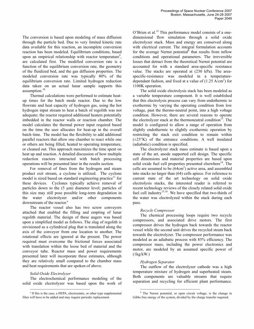
The conventional approach to hydrogen separation involves cooling and condensing out the liquid water. However, the recycled streams would require a reheat operation and the overall system efficiency would suffer. Inorganic membrane technologies offer the promise of high purity hydrogen separation for gas phase mixtures. A well known technology for ultra-high-purity hydrogen gas separation is the palladium membrane. Only monatomic hydrogen can diffuse through the crystal structure of Palladium at temperatures above 300C. Yet the hydrogen flux is proportional to the square root of the trans-membrane pressure and this demands a substantial re-compression of recycled flow streams. Another inorganic membrane separator utilizes a different approach to gas phase hydrogen separation. The technology, under development at Oak Ridge National Laboratory, is based upon Knudsen diffusion through microporous membranes17. The separation can occur at high temperatures, and the hydrogen flux is linearly proportional to the trans-membrane pressure. These benefits are traded against the lower purity hydrogen stream that permeates through the porous metallic membrane. However, purity values in excess of 90% are readily achievable. Optimal performance can result from trading the trans-membrane pressure (compressor work), membrane area (component mass) and hydrogen purity (hydrogen reduction reactor efficiency) against each other at the system level. For this analysis, the pressure drop was arbitrarily fixed at a mid range value that roughly balanced the pressure loss penalty against the separator unit mass.
Outflow of the Knudsen separation process can be modeled as two streams: the permeate (hydrogen rich) and the raffinate (steam rich) as seen in Figure 3. Bischoff and Judkins define a separation factor (SF) as a shown in Eq. 2:
32
2
2
2
2
2 ≈=⎟⎟⎠
⎞⎜⎜⎝
⎛•⎟⎟
⎠
⎞⎜⎜⎝
⎛=
H
OHM
MInflow
H
OH
Permeate
OH
H
PP
PPSF
Eq. 2
Using this relationship together with mass conservation, one can solve for permeate and raffinate stream compositions with a few assumptions. First, the trans-membrane pressure must be specified. This pressure is a system level variable and drives the diffusion process. Second, the diffusion process must be assumed to proceed until the partial pressure of hydrogen equilibrates across the porous membrane. This presumes that the residence time within the device corresponds to the diffusion time scale across the membrane at a given pressure. Finally, we assume that the feed stream travels down the length of the separation tube in a constant pressure flow before exiting as the raffinate stream.
Figure 3 Knudsen flow hydrogen separation.
The physical dimensions are built upon the concept of bundled membrane tubes, of one-meter length, all housed within a cylindrical shell. The tube is comprised of a two-micron-thick active layer and a five-hundred micron thick support layer. For mass estimation, both layers are specified at 50% porous hastelloy. The permeability of the active layer was specified as 1.34E-8 kg/(s m2 Pa), according to reference18. The center-to-center spacing between adjacent tubes was specified as three tube radii. The outer cylindrical shell housing was modeled as two-millimeter thick aluminum alloy. This unit requires no input power, with the exception of an initial heating to operating temperature. However, the recycle compressors discussed earlier were closely coupled to the separator performance. The compressors are responsible for making up any pressure lost during this separation process.
II.C. Cryogenic cooling and storage sub-system The cryogenic cooling system was formulated as a
multi-stage system to bring the oxygen from superheated gas to liquid state. Oxygen gas is sent first through a radiator sized to bring the gas to the saturation temperature at the specified tank pressure of 2 bar. The radiator mass is based on an assumed (6.1 kg/m2) value and a 15% effectiveness.
The saturated oxygen is then sent through a cryocooler sized to fully liquefy the gas. A second independent cryocooler is sized to prevent boiloff due to tank radiation at a worst case lunar surface ambient temperature of (373ºK) and conduction through structural components. A loss factor of 40% of the boiloff loss is assumed as an initial estimation of the heat lost via structural conduction. Both cryocoolers include radiators to remove the heat necessary.
The cryocooler model is based upon the work of Kittel19 . The ter Brake limit is used to estimate the losses beyond the Carnot limit as a function of cooling load required. A second correlation from ter Brake is used to estimate the cryocooler mass as a function of the power required. The two radiators are sized as above.
The liquid oxygen storage tanks are sized as spherical Al 2024 tanks with multi-layer insulation (MLI) blankets. Fifty individual layers of MLI are assumed to be required. The total ullage is assumed to be 7% above the amount of oxygen required. The tank wall thickness was sized based on the spherical pressure vessel stress equation with a safety factor of two, relative to the ultimate stress of the tank material.
Proceedings of Space Nuclear Conference 2007 Boston, Massachusetts, June 24-28 2007
Paper 2049
III. FISSION POWER SYSTEMS
Several power system models are included in the software to adjust for different mission concepts. While both solar and fission power models are available, we focused on the nuclear options for the present work. We have relied upon the recent efforts of Mason20 for selecting six reactor and converter systems for analysis here: • LT-BR: Low temperature stainless steel reactor (HeXe
cooled) directly coupled to a closed cycle Brayton converter
• HT-BR: Higher temperature refractory alloy reactor (HeXe cooled) directly coupled to a closed cycle Brayton converter
• LT-ST: Low temperature stainless steel reactor (NaK cooled) coupled with a high pressure helium Stirling converter via liquid metal heat pipe heat exchangers
• HT-ST: Higher temperature refractory alloy reactor (Li cooled) coupled with a high pressure helium Stirling converter via liquid metal heat pipe heat exchangers
• LT-TE: Low temperature stainless steel reactor (NaK cooled) coupled to a liquid metal thermoelectric converter via compact heat exchangers
• HT-TE: High temperature refractory alloy reactor (Li cooled) coupled to a liquid metal thermoelectric converter via compact heat exchangers
All three converters utilize pumped heat pipe radiator systems for heat rejection.
Reactor-converter system mass type slope (kg/kWe) intercept (kg) LT-BR 54.65 2927 HT-BR 28.45 2776 LT-ST 46.32 2987 HT-ST 38.21 2776 LT-TE 114.96 2565 HT-TE 61.52 2455
Table 1 Specific power regressions20 for six different reactor-converter combinations from 25kWe - 200kWe.
Mason20 points out that onboard shielding effectively doubles the mass of all six reactor options listed above. With this in mind, the mass of any additional shielding is not accounted for; it is assumed that excavation and burial of the reactor will be accomplished in situ. Specific power regression curves are presented in Mason and given here for completeness. The linear regressions are strictly valid for scaling within the range of (25 – 200 kWe). We have extended the range down to the (20kWe) to accommodate the present analysis. We have paid particular attention to the LT-ST, LT-TE, and HT-BR systems for the following analysis.
IV. SYSTEM LEVEL OPTIMIZATION
Thus far an overview has been presented of the two sub-systems that together operate to process raw material into usable oxygen and cool that oxygen for storage and later usage. The specific component models that operate together to enable this integrated analysis have been presented as well. System level optimization is responsible for tying these various component models together so that overall results can be analyzed. This system model has been constructed with Excel workbooks that either function as independent component models, or as a linked system. Each component can have variables that may influence the overall system performance, as well as variables that are of component level interest only. Together, the linked component workbooks function to produce a target oxygen production rate with minimum system mass (including power system). This is achieved by manipulating the system level variables within prescribed ranges. The optimization process is constrained by several physical limitations. The set of system level variables, objective function, and solution constraints are listed together in Table 2. The generalized reduced gradient solution methodology within the standard Excel Solver distribution is used for solution of this constrained optimization problem.
System Optimization
System Level Parameters kg Mass of regolith per reduction-reactor batch cm Diameter (inside) of the reduction-reactor mins Time allotted to heat up one batch of Regolith batch/day Number of regolith batches per 24 hour 'day' mA/cm2 Current density of steam electrolysis stacks
Goal Parameter m-Ton/yr Annual oxygen production target
Objective Function kg Total mass of system
Equality Constraints m-Ton/yr (Actual – Target) oxygen production (→0)
Inequality Constraintsc hr Batch time ≥ H2 reduction reaction time
hr Batch time ≥ regolith feed, heat up, and dump time
deg K Temperature change across stack (|∆T|< 25°C)
Table 2 System level optimization parameters.
The above optimization strategy represents an initial capability. The system level parameters are all continuous variables at this time. However, integer variables can be incorporated as well. For instance, the number of hydrogen reactors can have an important effect upon the component sizing. Also note that power requirements have been
c These inequality constraints depend upon the concept of operations.

Proceedings of Space Nuclear Conference 2007 Boston, Massachusetts, June 24-28 2007
Paper 2049
incorporated through the power system mass alone. A more sophisticated objective function could be constructed that incorporates mass, power and volume requirements directly through subjectively weighted cost values. These issues have been left for future analysis.
IV. RESULTS The system analysis results will be presented in three
sub-sections. The first section will cover the mass and power requirements for a baseline configuration and introduce the concept of component effective mass. The second sub-section will assess the interaction of component sizing with the choice of fission reactor-converter technology. The final sub-section will assess the influence of choosing either single or multiple hydrogen reduction reactors.
IV.A Baseline Configuration Results
A baseline configuration was specified with the following attributes: • Two hydrogen reduction reactors • LT-ST reactor-converter power system • Fifteen metric ton per year oxygen production target The significance of multiple hydrogen reactors will be covered in the following section. The LT-ST power system was chosen for its combination of near-term technology readiness and good specific power. The oxygen production target is representative of requirements for a lunar outpost that requires both ascent propellant and human life support.
LT-ST: Two H2-Reduction Reactors
0
50
100
150
200
250
300
BOPcomponents
H2 Reactors Electrolyzerstacks
Cryo O2 sub-system
Mas
s (k
g)
Figure 4 Component mass requirements for the baseline configuration.
Figure 4 displays the dominant component mass values for the baseline system, with the exception of the power system. The LT-ST power system mass was 3988 kg. The heaviest components are the cryogenic oxygen cooling and storage sub-system, followed by the electrolyzer stacks and hydrogen reduction reactors. The
balance-of-plant (BOP) components are cumulatively less than the reactors.
Figure 5 reveals the dominant component power requirements. From this perspective, the hydrogen reduction reactors, responsible for heating the regolith from ambient to reaction temperature, were the major power requirement. While the energy required for this process was fixed by the target production rate, the peak power expended was naturally a function of the actual time spent on the heating process. This implies that the hydrogen reactor power was heavily dependant upon the concept of operations. This reactor power requirement will be discussed in depth in section IV.C.
Two other components had relatively high power consumption rates: the electrolyzer stacks and the hydrogen recycle compressor. Electrolysis converts electrical energy to stored chemical energy, and so is expected to have a significant power requirement. However, the hydrogen recycle compressor was surprising. The high temperature hydrogen separation process resulted in a significant pressure drop across the device, and this must be made up via re-compression. A trade is possible between the assigned pressure drop and the separator mass, and this will be investigated further in the future. The balance of plant components together required less power than the hydrogen recycle compressor.
LT-ST: Two H2-Reduction Reactors
0123456789
10
BOPComponents
H2compressor
Electrolyzerstacks
H2 Reactors
Pow
er (k
We)
Figure 5 Component power requirements for the baseline configuration.
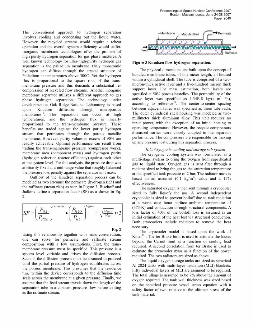
Our optimization was based upon minimizing the mass of the entire system, including the plant and fission power system. Another way to express this idea was to assign to each component a proportional amount of the peak power system mass. Thus, each plant component has its own mass plus the additional mass associated with the component power requirement. We have called this an effective mass for each component. The effective mass results are shown in Figure 6. The largest effective mass components are the hydrogen reduction reactor, the electrolysis stacks, the cryogenic oxygen sub-system, and
Proceedings of Space Nuclear Conference 2007 Boston, Massachusetts, June 24-28 2007
Paper 2049
the hydrogen recycle compressor. We can see that this result combines the trends evident in Figure 4 and Figure 5 above. Effective mass highlights specific components for improved modeling fidelity and design.
LT-ST: Two H2-Reduction Reactors
0200400600800
10001200140016001800
BOP compo
nents
H2 com
press
or
Cryo O
2 sub
-syste
m
Electro
lyzer
stack
s
H2 Rea
ctors
Effe
ctiv
e M
ass
(kg)
Figure 6 Effective mass requirements for the baseline system.
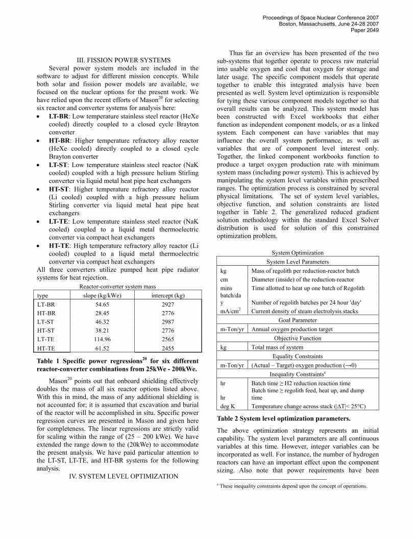
IV.B. Influence of Reactor-Converter Type From inspection of the fission reactor data of Table 1,
one can see that there was a considerable range of specific power (kWe/kg) available. The baseline LT-ST configuration was compared to two additional fission reactor – converter combinations. For a given power level, the lightest technology was HT-BR while the heaviest technology was the LT-TE. Note that the nearest term, and perhaps the most affordable technology was the baseline LT-ST. We have compared the optimized results of these three cases below in Figure 7.
0
1000
2000
3000
4000
5000
6000
LT-TE LT-ST HT-BR
Fission Reactor-Converters
Pow
er S
yste
m M
ass
(kg)
21.1
21.2
21.3
21.4
21.5
21.6
21.7
21.8
Pow
er D
eliv
ered
(kW
e)
Power mass
Total power
Figure 7 Comparison of fission reactor-converters: power and mass for a 15 metric ton per year oxygen production target.
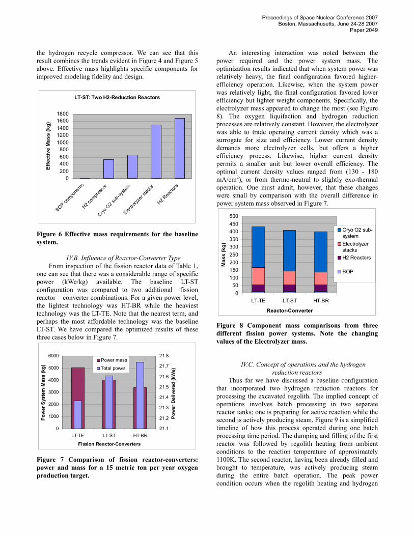
An interesting interaction was noted between the power required and the power system mass. The optimization results indicated that when system power was relatively heavy, the final configuration favored higher-efficiency operation. Likewise, when the system power was relatively light, the final configuration favored lower efficiency but lighter weight components. Specifically, the electrolyzer mass appeared to change the most (see Figure 8). The oxygen liquifaction and hydrogen reduction processes are relatively constant. However, the electrolyzer was able to trade operating current density which was a surrogate for size and efficiency. Lower current density demands more electrolyzer cells, but offers a higher efficiency process. Likewise, higher current density permits a smaller unit but lower overall efficiency. The optimal current density values ranged from (130 - 180 mA/cm2), or from thermo-neutral to slightly exo-thermal operation. One must admit, however, that these changes were small by comparison with the overall difference in power system mass observed in Figure 7.
050
100150200250300350400450500
LT-TE LT-ST HT-BR
Reactor-Converter
Mas
s (k
g)Cryo O2 sub-systemElectrolyzerstacksH2 Reactors
BOP
Figure 8 Component mass comparisons from three different fission power systems. Note the changing values of the Electrolyzer mass.
IV.C. Concept of operations and the hydrogen reduction reactors
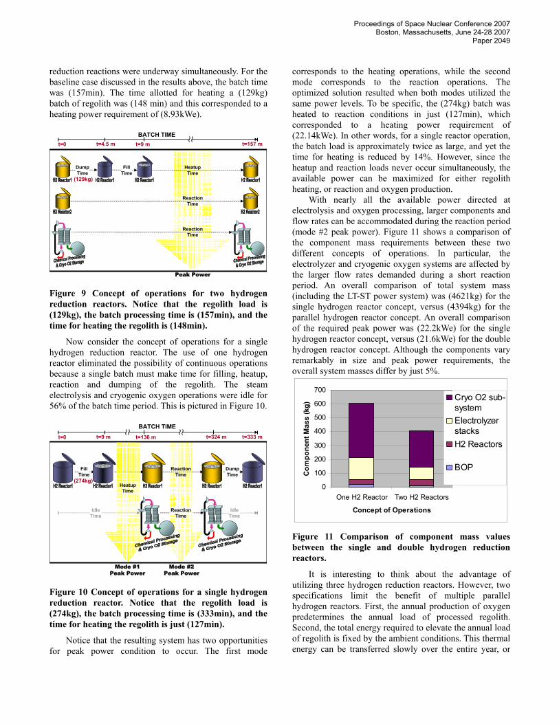
Thus far we have discussed a baseline configuration that incorporated two hydrogen reduction reactors for processing the excavated regolith. The implied concept of operations involves batch processing in two separate reactor tanks; one is preparing for active reaction while the second is actively producing steam. Figure 9 is a simplified timeline of how this process operated during one batch processing time period. The dumping and filling of the first reactor was followed by regolith heating from ambient conditions to the reaction temperature of approximately 1100K. The second reactor, having been already filled and brought to temperature, was actively producing steam during the entire batch operation. The peak power condition occurs when the regolith heating and hydrogen
Proceedings of Space Nuclear Conference 2007 Boston, Massachusetts, June 24-28 2007
Paper 2049
reduction reactions were underway simultaneously. For the baseline case discussed in the results above, the batch time was (157min). The time allotted for heating a (129kg) batch of regolith was (148 min) and this corresponded to a heating power requirement of (8.93kWe).
BATCH TIME
Peak Power
ReactionTime
ReactionTime
t=0 t=4.5 m t=9 m t=157 m
FillTime
DumpTime
HeatupTime
(129kg)
Figure 9 Concept of operations for two hydrogen reduction reactors. Notice that the regolith load is (129kg), the batch processing time is (157min), and the time for heating the regolith is (148min).
Now consider the concept of operations for a single hydrogen reduction reactor. The use of one hydrogen reactor eliminated the possibility of continuous operations because a single batch must make time for filling, heatup, reaction and dumping of the regolith. The steam electrolysis and cryogenic oxygen operations were idle for 56% of the batch time period. This is pictured in Figure 10.
BATCH TIME
FillTime
ReactionTime
DumpTime
ReactionTime
IdleTime
IdleTime
Mode #1Peak Power
Mode #2Peak Power
HeatupTime
t=0 t=9 m t=136 m t=333 mt=324 m
(274kg)
Figure 10 Concept of operations for a single hydrogen reduction reactor. Notice that the regolith load is (274kg), the batch processing time is (333min), and the time for heating the regolith is just (127min).
Notice that the resulting system has two opportunities for peak power condition to occur. The first mode
corresponds to the heating operations, while the second mode corresponds to the reaction operations. The optimized solution resulted when both modes utilized the same power levels. To be specific, the (274kg) batch was heated to reaction conditions in just (127min), which corresponded to a heating power requirement of (22.14kWe). In other words, for a single reactor operation, the batch load is approximately twice as large, and yet the time for heating is reduced by 14%. However, since the heatup and reaction loads never occur simultaneously, the available power can be maximized for either regolith heating, or reaction and oxygen production.
With nearly all the available power directed at electrolysis and oxygen processing, larger components and flow rates can be accommodated during the reaction period (mode #2 peak power). Figure 11 shows a comparison of the component mass requirements between these two different concepts of operations. In particular, the electrolyzer and cryogenic oxygen systems are affected by the larger flow rates demanded during a short reaction period. An overall comparison of total system mass (including the LT-ST power system) was (4621kg) for the single hydrogen reactor concept, versus (4394kg) for the parallel hydrogen reactor concept. An overall comparison of the required peak power was (22.2kWe) for the single hydrogen reactor concept, versus (21.6kWe) for the double hydrogen reactor concept. Although the components vary remarkably in size and peak power requirements, the overall system masses differ by just 5%.
0
100
200
300
400
500
600
700
One H2 Reactor Two H2 Reactors
Concept of Operations
Com
pone
nt M
ass
(kg)
Cryo O2 sub-systemElectrolyzerstacksH2 Reactors
BOP
Figure 11 Comparison of component mass values between the single and double hydrogen reduction reactors.
It is interesting to think about the advantage of utilizing three hydrogen reduction reactors. However, two specifications limit the benefit of multiple parallel hydrogen reactors. First, the annual production of oxygen predetermines the annual load of processed regolith. Second, the total energy required to elevate the annual load of regolith is fixed by the ambient conditions. This thermal energy can be transferred slowly over the entire year, or

Proceedings of Space Nuclear Conference 2007 Boston, Massachusetts, June 24-28 2007
Paper 2049
transferred more quickly over a portion of the year. The former approach is achieved when continuous operation is specified, and results in the lower limit of heating power. The latter approach results from intermittent heating, and results in elevated heating power requirements. The single reactor concept of operations utilizes just 38% of the available time for heating, while the two reactor concept uses 94% of the available time. By using two reactors instead of one, we have nearly achieved a continuous operation. The marginal power reduction available from a three hydrogen reactor scenario does not make up for the additional equipment required. The three hydrogen reactor system was (9kg) heavier and just (0.13kWe) more efficient than the two reactor system.
IV. CONCLUSIONS
We have developed a detailed systems model for the
simulation of hydrogen reduction of lunar ilmenite. The process involved an integrated approach from chemical processing of beneficiated regolith through the cryogenic storage of lunar oxygen. Individual component performance and mass models were presented. An optimization process that minimizes the system mass, including a fission power and converter system, was shown to reveal several component interactions. The presentation of mass and power requirements can be combined with the use of an effective component mass. This highlights the most critical components that deserve further attention, both in terms of modeling fidelity and design improvement. For the baseline configuration, the components with the highest effective mass were: 1. hydrogen reduction reactor and regolith heater 2. High-temperature electrolysis stacks 3. Cryogenic oxygen cooling and storage sub-system 4. Recycled hydrogen compressor The compressor size was driven by the large pressure drop across the high temperature hydrogen separator. This was arbitrarily specified and should be an optimized variable in future analysis.
Three different fission power systems were considered: 1. low-temperature, NaK cooled stainless steel reactor
and thermoelectric converter 2. low-temperature, NaK cooled stainless steel reactor
and Stirling converter (baseline system) 3. high-temperature, HeXe cooled refractory reactor
directly coupled to a closed cycle Brayton converter An interaction was observed between the reactor type and the high temperature electrolysis operating point. The highest specific-power system (high temperature Brayton) allowed for a smaller but less efficient electrolysis system when compared to the baseline. Likewise, the lowest specific power (low temperature thermoelectric) allowed for a larger but more efficient electrolysis system. The
operating point for electrolysis ranged from the thermo-neutral condition to slightly exothermic.
Finally, the significant power requirement of the regolith heating process can be optimized with a concept of operations that involves parallel hydrogen reaction and heating operations in separate reactor tanks. The best performance was seen when two reduction reactors were specified.
ACKNOWLEDGMENTS The authors would like to acknowledge Juan Agui for
his contribution to the modeling of the regolith feed and dump auger systems; Suleyman Gokoglu, Uday Hegde, and Ramaswamy Balasubramaniam for their help with reduction reactor and hydrogen separator modeling; and James O’Brien and Grant Hawkes for their comments regarding solid oxide electrolysis.
NOMENCLATURE NASA National Aeronautics and Space
Administration EVA Extra vehicular activity ISRU In situ resource utilization O Oxygen H Hydrogen Fe Iron Ti Titanium Mg Magnesium HeXe Helium Xenon gas NaK Sodium potassium liquid metal g Earth’s gravitational constant Mi Molecular weight of species “i” Pi Partial pressure of species “i” MLI Multi layer insulation LT-BR Low temp nuclear reactor + Brayton converter HT-BR High temp nuclear reactor + Brayton converter LT-ST Low temp nuclear reactor + Stirling converter HT-ST High temp nuclear reactor + Stirling converter LT-TE Low temp nuclear reactor + Thermoelectric
converter HT-TE High temp nuclear reactor + Thermoelectric
converter SF Hydrogen separation factor
1 G. H. Heiken, D. T. Vaniman, and B. M. French, Lunar Sourcebook; a User’s Guide to the Moon, Chapters 5-7, Cambridge University Press, Cambridge (1991) 2 L. A. Taylor, D. S. McKay, “An Ilmenite Feedstock on the Moon: Beneficiation of Rocks Versus Soil,” Abstracts of the Lunar and Planetary Science Conference, vol 23, page 1411, (1992)

Proceedings of Space Nuclear Conference 2007 Boston, Massachusetts, June 24-28 2007
Paper 2049
3 L. A. Taylor and W. D. Carrier III, “Production of Oxygen on the Moon: Which Processes Are Best and Why,” AIAA Journal, Vol. 30, No. 12, December (1992) 4 L. Clark, “Integrated In-Situ Resource Utilization for Human Exploration – Propellant Production for the Moon and Beyond,” Phase 1 Final Report, NASA Contract: NNJ05HB57C, October (2006) 5 R. Oder and L. Taylor, “Magnetic Beneficiation of Highland and Hi-Ti Mare Soils: Magnetic Requirements,” Proc. Space 90, S. W. Johnston and J. P. Wetzel, Eds., Albuquerque, New Mexico, April (1990) 6 S. Gordon and B. McBride, “Computer Program for Calculation of Complex Chemical Equilibrium Compositions and Applications,” NASA Reference Publication 1311, October (1994) 7 Kunii D. & Levenspiel O., Fluidization Engineering, 2nd edition, Butterworth Heinemann: Boston, 1991 8 Brueneman, D. J., Sorge, L. L., Gibson, M. A., Knudsen, C. W., and Kanamori, H., “Digital image analysis of two-dimensional fluidized beds at lunar gravity”, Proc. of the Fifth Int. Conf. on Space, Albuquerque, New Mexico, June 1-6 (1996) 9 Erstfield, T. E.; Williams, R. J., “High temperature electrolytic recovery of oxygen from gaseous effluents from the carbo-chlorination of lunar anorthite and the hydrogenation of ilmenite: A theoretical study,” JSC-14649; NASA-TM-58214 (1979) 10 Gibson M.A., Knudsen C.W., Brueneman D.J., Allen C.C., Kanamori H., & McKay D.S., “Reduction of Lunar Basalt 70035 - oxygen yield and reaction product analysis”, Journal of Geophysical Research, vol. 99, p. 10887-10897. 11 Perry, R. H., Perry’s Chemical Engineers’ Handbook, D. W. Green, editor, 7th edition, McGraw-Hill: New York (1997) 12 J. E. O’Brien, C. M. Stoots, J. S. Herring, and G. L. Hawkes, “Comparison of a One-Dimensional Model of a High-Temperature Solid-Oxide Electrolysis Stack with CFD and Experimental Results,” IMECE2005-81921, Proc. of 2005 ASME Int. Mech. Eng. Cong. and Expo., Orlando, FL, Nov. (2005), 13 J. E. O’Brien, C. M. Stoots, J. S. Herring, G. L. Hawkes, HYDROGEN PRODUCTION FROM NUCLEAR ENERGY VIA HIGH TEMPERATURE ELECTROLYSIS, 1st Energy Center Hydrogen Initiative Symposium, Purdue University, Paper #ECHI-I-IL-3, West Lafayette, IN, April (2006) 14 Tornabene, R., Wang, X.-Y., Steffen, C.J. Jr., Freeh, J.E., (2005) “Development of Parametric Mass and Volume Models for an Aerospace SOFC/Gas Turbine Hybrid System,” ASME GT-2005-68334, ASME Turbo Expo, Reno, NV, USA (2005) 15 Assessment of Solid Oxide Fuel Cell Technology: Comparisons of Alternative Design Approaches,
EPRIsolutions, Palo Alto, CA: 2002. 1003966 16 Handbook of Fuel Cells: Fundamentals, Technology, Applications, 4-Volume Set, Vielstich, W., Lamm, A. and Gasteiger H., Editors, ISBN: 0-471-49926-9, May 2003. 17 B. L. Bischoff, R. R. Judkins, and L. E. Powell, “Application of Inorganic Membranes to High Temperature Electrolysis,” Oak Ridge National Laboratory report ORNL/TM-2005/524, Sep. (2005) 18 B. L. Bischoff, R. R. Judkins, K. D. Alcock, and L. E. Powell, “Development of Inorganic Membranes for Hydrogen Separation,” in Proc. of 17th Annual Conference on Fossil Energy Materials, 2003. 19 P. Kittel, "Cryocooler Performance Estimator," 14th Int. Cryocooler Conf., Annapolis, MD, June 14-16, 2006. 20 L. S. Mason, “A Comparison of Fission Power System Options for Lunar and Mars Surface Applications,” NASA Technical Memorandum 2006-214120, Cleveland, OH (2006)


![Lunar&Dynamical&Modeling& with&Improved&IRLunar&Laser ... · Lunar&Dynamical&Modeling& with&Improved&IRLunar&Laser&Ranging&data& V.Viswanathan [1,2], A.Fienga[1], H.Manche[2], C.Courde[1],](https://img.pdfslide.net/doc/110x75/60362aef580c2647732639d6/lunardynamicalmodeling-withimprovedirlunarlaser-.jpg)