Embed Size (px)
Citation preview
Organization Blocks 1
Common Parameters for SFCs
2
Copy and Block Functions
3
SFCs for Controlling Program Execution
4
SFCs for Handling the System Clock
5
SFCs for Handling Run-Time Meters
6
SFCs/SFBs for Transferring Data Records
7
DPV1 SFBs According to PNO AK 1131
8
SFCs for Handling Time-of-Day Interrupts
9
SFCs for Handling Time-Delay Interrupts
10
SFCs for Handling Synchronous Errors
11
SFCs for Handling Interrupts and Asynchronous Errors
12
SFCs for Diagnostics
13
SFCs and SFBs for Updating the Process Image and Processing Bit Fields
14
System Functions for Addressing Modules
15
SFCs for Distributed I/Os or PROFINET IO
16
PROFINET
17
SFCs and SFBs for PROFINET CPUs
18
SIMATIC
System Software for S7-300/400 System and Standard Functions Volume 1/2
Reference Manual
05/2010 A5E02789976-01
This manual is part of the documentation package with the order number: 6ES7810-4CA10-8BW1
Legal information Warning notice system
This manual contains notices you have to observe in order to ensure your personal safety, as well as to prevent damage to property. The notices referring to your personal safety are highlighted in the manual by a safety alert symbol, notices referring only to property damage have no safety alert symbol. These notices shown below are graded according to the degree of danger.
DANGER indicates that death or severe personal injury will result if proper precautions are not taken.
WARNING indicates that death or severe personal injury may result if proper precautions are not taken.
CAUTION with a safety alert symbol, indicates that minor personal injury can result if proper precautions are not taken.
CAUTION without a safety alert symbol, indicates that property damage can result if proper precautions are not taken.
NOTICE indicates that an unintended result or situation can occur if the corresponding information is not taken into account.
If more than one degree of danger is present, the warning notice representing the highest degree of danger will be used. A notice warning of injury to persons with a safety alert symbol may also include a warning relating to property damage.
Qualified Personnel The product/system described in this documentation may be operated only by personnel qualified for the specific task in accordance with the relevant documentation for the specific task, in particular its warning notices and safety instructions. Qualified personnel are those who, based on their training and experience, are capable of identifying risks and avoiding potential hazards when working with these products/systems.
Proper use of Siemens products Note the following:
WARNING Siemens products may only be used for the applications described in the catalog and in the relevant technical documentation. If products and components from other manufacturers are used, these must be recommended or approved by Siemens. Proper transport, storage, installation, assembly, commissioning, operation and maintenance are required to ensure that the products operate safely and without any problems. The permissible ambient conditions must be adhered to. The information in the relevant documentation must be observed.
Trademarks All names identified by ® are registered trademarks of the Siemens AG. The remaining trademarks in this publication may be trademarks whose use by third parties for their own purposes could violate the rights of the owner.
Disclaimer of Liability We have reviewed the contents of this publication to ensure consistency with the hardware and software described. Since variance cannot be precluded entirely, we cannot guarantee full consistency. However, the information in this publication is reviewed regularly and any necessary corrections are included in subsequent editions.
Siemens AG Industry Sector Postfach 48 48 90026 NÜRNBERG GERMANY
A5E02789976-01 Ⓟ 02/2010
Copyright © Siemens AG 2010. Technical data subject to change
System Software for S7-300/400 System and Standard Functions Volume 1/2 Reference Manual, 05/2010, A5E02789976-01 3
Preface
Purpose This manual provides you with a comprehensive overview of the organization blocks (OB), system functions (SFC), system and standard function blocks (SFC), and IEC functions contained in the operating systems of the CPUs of the S7-300 and S7-400, diagnostic data, system status lists (SZL), and events.
Note
Refer to the reference section of the "S7-300 Automation System CPU Specifications: CPU 31xC and CPU 31x" and "S7-300 Automation System CPU Specifications: CPU 312IFM - 318-2 DP“ /70/ or the "Automation System S7-400: CPU Specifications" reference manual /101/ or the Instruction List: S7-400 Programmable Controller /102/ (whichever version applies to your CPU) for details of which of these functions and blocks are available on which CPU. The properties of the CFBs and the S7 signaling functions for specific CPUs are described in /70/ and /101/.
For information about the CPU operating systems, program design, and the communications and diagnostic capabilities of the CPUs, refer to the "Configuring Hardware and Communication Connections STEP 7 V5.5" manual /234/ How to call functions and function blocks in your program is explained in the language descriptions.
You program and assign parameters for all these functions using the STEP 7 standard software. How to use this software is described in the "Programming with STEP 7 V5.5" manual /231/ and in the STEP 7 online help.
Audience This manual is intended for programmers and engineers who are familiar with controlling processes and are responsible for writing programs for programmable logic controllers.
Preface
System Software for S7-300/400 System and Standard Functions Volume 1/2 4 Reference Manual, 05/2010, A5E02789976-01
STEP 7 Documentation Packages The following table displays an overview of the STEP 7 documentation: Documentation Purpose Order Number
STEP 7 Basic Information with • Working with STEP 7,
Getting Started Manual • Programming with STEP 7 • Configuring Hardware and
Communication Connections, STEP 7 • From S5 to S7, Converter Manual
Basic information for technical personnel describing the methods of implementing control tasks with STEP 7 and the S7-300/400 programmable controllers.
6ES7810-4CA10-8BW0
STEP 7 Reference with • Ladder Logic (LAD)/Function Block
Diagram (FBD)/Statement List (STL) for S7-300/400 manuals
• Standard and System Functions for S7-300/400 Volume 1 and Volume 2
Provides reference information and describes the programming languages LAD, FBD, and STL, and standard and system functions extending the scope of the STEP 7 basic information.
6ES7810-4CA10-8BW1
Online Helps Purpose Order Number
Help on STEP 7 Basic information on programming and configuring hardware with STEP 7 in the form of an online help.
Part of the STEP 7 Standard software.
Reference helps on STL/LAD/FBD Reference help on SFBs/SFCs Reference help on Organization Blocks
Context-sensitive reference information.
Part of the STEP 7 Standard software.
Preface
System Software for S7-300/400 System and Standard Functions Volume 1/2 Reference Manual, 05/2010, A5E02789976-01 5
Online Help The manual Volume 1 and Volume 2 is complemented by an online help which is integrated in the software. This online help is intended to provide you with detailed support when using the software. The help system is integrated in the software via a number of interfaces:
• There are several menu commands which you can select in the Help menu: The Contents command opens the index for the Help on STEP 7.
• Using Help provides detailed instructions on using the online help.
• The context-sensitive help offers information on the current context, for example, an open dialog box or an active window. You can open the context-sensitive help by clicking the "Help" button or by pressing F1.
• The status bar offers another form of context-sensitive help. It displays a short explanation for each menu command when the mouse pointer is positioned on the menu command.
• A brief explanation is also displayed for each icon in the toolbar when the mouse pointer is positioned on the icon for a short time.
If you prefer to read the information from the online help in printed format, you can print out individual help topics, books, or the entire online help.
This manual is an extract from the HTML-based Help on STEP 7. As the manual and the online help share an almost identical structure, it is easy to switch between the manual and the online help.
Feedback on Documentation To help us to provide the best possible documentation for you and future STEP 7 users, we need your support. If you have any comments or suggestions relating to this manual or the online help, please complete the questionnaire at the end of the manual and send it to the address shown. Please include your own personal rating of the documentation.
Other Manuals The various S7-300 and S7-400 CPUs and the S7-300 and S7-400 modules are described in the following manuals:
• For the S7-300 programmable logic controller, refer to the manuals: "PLC S7-300, CPU Specifications CPU 312 IFM to CPU 318-2 DP and S7-300 CPU 31xC and CPU 31x: Technical specifications“ /70/, "S7-300 S7-300 Module data" /71/ and in the Instruction List /72/.
• For the S7-400 programmable logic controller, refer to the manual: "S7-400 Automation System: Module Data" /101/ and in the Instruction List /102/.
Preface
System Software for S7-300/400 System and Standard Functions Volume 1/2 6 Reference Manual, 05/2010, A5E02789976-01
How to Use this Manual This manual covers the following topics:
• Chapter 1 explains the functions of all the organization blocks.
• Chapter 2 describes the common parameters RET_VAL, REQ and BUSY.
• Chapters 3 to 32 describe the SFCs, SFBs and IEC-FCs.
• The Chapters sections 33 to 36 contain a description of the structure of the diagnostic data, an overview of the SZL-IDs, the possible events, lists of the SFCs, SFBs and FCs described in this manual, an overview of the SDBs.
• The bibliography contains a list of further manuals.
• The Glossary explains important terminology.
• The Index helps you to locate sections of text and topics quickly.
Conventions References to other manuals and documentation are indicated by numbers in slashes /.../. These numbers refer to the titles of manuals listed in the bibliography.
Special Note The system functions can be interrupted. If there are any restrictions that apply to certain SFCs or situations, these are explained in the description of the particular SFC.
Further Support If you have any technical questions, please get in touch with your Siemens representative or responsible agent.
You will find your contact person at:
http://www.siemens.com/automation/partner
You will find a guide to the technical documentation offered for the individual SIMATIC Products and Systems at:
http://www.siemens.com/simatic-tech-doku-portal
The online catalog and order system is found under:
http://mall.automation.siemens.com/
Training Centers Siemens offers a number of training courses to familiarize you with the SIMATIC S7 automation system. Please contact your regional training center or our central training center in D 90026 Nuremberg, Germany for details: Internet: http://www.sitrain.com
Preface
System Software for S7-300/400 System and Standard Functions Volume 1/2 Reference Manual, 05/2010, A5E02789976-01 7
Technical Support You can reach the Technical Support for all Industry Automation and Drive Technology products
• Via the Web formula for the Support Request http://www.siemens.com/automation/support-request
Additional information about our Technical Support can be found on the Internet pages http://www.siemens.com/automation/service
Service & Support on the Internet In addition to our documentation, we offer our Know-how online on the internet at: http://www.siemens.com/automation/service&support
where you will find the following:
• The newsletter, which constantly provides you with up-to-date information on your products.
• The right documents via our Search function in Service & Support.
• A forum, where users and experts from all over the world exchange their experiences.
• Your local representative for Industry Automation and Drive Technology.
Information on field service, repairs, spare parts and consulting.

Preface
System Software for S7-300/400 System and Standard Functions Volume 1/2 8 Reference Manual, 05/2010, A5E02789976-01
System Software for S7-300/400 System and Standard Functions Volume 1/2 Reference Manual, 05/2010, A5E02789976-01 9
Contents
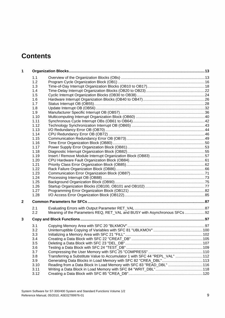
1 Organization Blocks..................................................................................................................................13 1.1 Overview of the Organization Blocks (OBs) ................................................................................13 1.2 Program Cycle Organization Block (OB1) ...................................................................................16 1.3 Time-of-Day Interrupt Organization Blocks (OB10 to OB17).......................................................18 1.4 Time-Delay Interrupt Organization Blocks (OB20 to OB23) ........................................................22 1.5 Cyclic Interrupt Organization Blocks (OB30 to OB38).................................................................24 1.6 Hardware Interrupt Organization Blocks (OB40 to OB47)...........................................................26 1.7 Status Interrupt OB (OB55)..........................................................................................................28 1.8 Update Interrupt OB (OB56) ........................................................................................................32 1.9 Manufacturer Specific Interrupt OB (OB57).................................................................................36 1.10 Multicomputing Interrupt Organization Block (OB60) ..................................................................40 1.11 Synchronous Cycle Interrupt OBs (OB61 to OB64).....................................................................42 1.12 Technology Synchronization Interrupt OB (OB65) ......................................................................43 1.13 I/O Redundancy Error OB (OB70) ...............................................................................................44 1.14 CPU Redundancy Error OB (OB72) ............................................................................................46 1.15 Communication Redundancy Error OB (OB73)...........................................................................49 1.16 Time Error Organization Block (OB80) ........................................................................................50 1.17 Power Supply Error Organization Block (OB81)..........................................................................53 1.18 Diagnostic Interrupt Organization Block (OB82)..........................................................................55 1.19 Insert / Remove Module Interrupt Organization Block (OB83) ....................................................57 1.20 CPU Hardware Fault Organization Block (OB84)........................................................................61 1.21 Priority Class Error Organization Block (OB85)...........................................................................62 1.22 Rack Failure Organization Block (OB86).....................................................................................66 1.23 Communication Error Organization Block (OB87) .......................................................................71 1.24 Processing Interrupt OB (OB88) ..................................................................................................73 1.25 Background Organization Block (OB90)......................................................................................75 1.26 Startup Organization Blocks (OB100, OB101 and OB102) .........................................................77 1.27 Programming Error Organization Block (OB121) ........................................................................82 1.28 I/O Access Error Organization Block (OB122).............................................................................85
2 Common Parameters for SFCs ................................................................................................................87 2.1 Evaluating Errors with Output Parameter RET_VAL ...................................................................87 2.2 Meaning of the Parameters REQ, RET_VAL and BUSY with Asynchronous SFCs ...................92
3 Copy and Block Functions .......................................................................................................................97 3.1 Copying Memory Area with SFC 20 "BLKMOV"..........................................................................97 3.2 Uninterruptible Copying of Variables with SFC 81 "UBLKMOV" ...............................................100 3.3 Initializing a Memory Area with SFC 21 "FILL" ..........................................................................102 3.4 Creating a Data Block with SFC 22 "CREAT_DB" ....................................................................105 3.5 Deleting a Data Block with SFC 23 "DEL_DB" ..........................................................................107 3.6 Testing a Data Block with SFC 24 "TEST_DB" .........................................................................109 3.7 Compressing the User Memory with SFC 25 "COMPRESS" ....................................................110 3.8 Transferring a Substitute Value to Accumulator 1 with SFC 44 "REPL_VAL" ..........................112 3.9 Generating Data Blocks in Load Memory with SFC 82 "CREA_DBL".......................................113 3.10 Reading from a Data Block In Load Memory with SFC 83 "READ_DBL" .................................116 3.11 Writing a Data Block in Load Memory with SFC 84 "WRIT_DBL".............................................118 3.12 Creating a Data Block with SFC 85 "CREA_DB".......................................................................120
Contents
System Software for S7-300/400 System and Standard Functions Volume 1/2 10 Reference Manual, 05/2010, A5E02789976-01
4 SFCs for Controlling Program Execution .............................................................................................123 4.1 Re-triggering Cycle Time Monitoring with SFC 43 "RE_TRIGR"...............................................123 4.2 Changing the CPU to STOP with SFC 46 "STP" .......................................................................123 4.3 Delaying Execution of the User Program with SFC 47 "WAIT" .................................................124 4.4 Triggering a Multicomputing Interrupt with SFC 35 "MP_ALM" .................................................125 4.5 Controlling CiR with SFC 104 "CiR"...........................................................................................126 4.6 Activating Write-protection with SFC 109 "PROTECT" .............................................................128
5 SFCs for Handling the System Clock ....................................................................................................131 5.1 Setting the TOD with SFC 0 "SET_CLK" ...................................................................................131 5.2 Reading the Time with SFC 1 "READ_CLK" .............................................................................132 5.3 Synchronizing Slave Clocks with SFC 48 "SNC_RTCB"...........................................................133 5.4 Setting the Time-of-Day and the TOD Status with SFC 100 "SET_CLKS" ...............................134
6 SFCs for Handling Run-Time Meters.....................................................................................................137 6.1 Runtime Meters..........................................................................................................................137 6.2 Handling Runtime meters with SFC 101 "RTM" ........................................................................139 6.3 Setting the Runtime Meter with SFC 2 "SET_RTM" ..................................................................141 6.4 Starting and Stopping a Run-time Meter with SFC 3 "CTRL_RTM"..........................................142 6.5 Reading a Runtime Meter with SFC 4 "READ_RTM"................................................................143 6.6 Reading the System Time with SFC 64 "TIME_TCK" ...............................................................144
7 SFCs/SFBs for Transferring Data Records...........................................................................................145 7.1 Writing and Reading Data Records ...........................................................................................145 7.2 Reading Defined Parameters with SFC 54 "RD_DPARM" ........................................................148 7.3 Reading Predefined Parameters with SFC 102 "RD_DPARA"..................................................149 7.4 Writing Dynamic Parameters with SFC 55 "WR_PARM" ..........................................................150 7.5 Writing Default Parameters with SFC 56 "WR_DPARM" ..........................................................152 7.6 Assigning Parameters to a Module with SFC 57 "PARM_MOD"...............................................153 7.7 Writing a Data Record with SFC 58 "WR_REC"........................................................................156 7.8 Reading a Data Record with SFC 59 "RD_REC" ......................................................................158 7.9 Further Error Information for SFCs 55 to 59 ..............................................................................163 7.10 Reading Predefined Parameters with SFB 81 "RD_DPAR" ......................................................163
8 DPV1 SFBs According to PNO AK 1131................................................................................................165 8.1 Reading a Data Record with SFB 52 "RDREC".........................................................................165 8.2 Writing a Data Record with SFB53 "WRREC"...........................................................................167 8.3 Receiving an Interrupt with SFB 54 "RALRM" ...........................................................................169 8.4 Sending an Interrupt to the DP Master with SFB 75 "SALRM"..................................................187 8.5 Receiving a Data Record with SFB 73 "RCVREC"....................................................................194 8.6 Providing a Data Record with SFB 74 "PRVREC".....................................................................197
9 SFCs for Handling Time-of-Day Interrupts ...........................................................................................201 9.1 Handling Time-of-Day Interrupts................................................................................................201 9.2 Characteristics of SFCs 28 to 31 ...............................................................................................202 9.3 Setting a Time-of-Day Interrupt with SFC 28 "SET_TINT" ........................................................204 9.4 Canceling a Time-of-Day Interrupt with SFC 29 "CAN_TINT"...................................................205 9.5 Activating a Time-of-Day Interrupt with SFC 30 "ACT_TINT"....................................................206 9.6 Querying a Time-of-Day Interrupt with SFC 31 "QRY_TINT" ....................................................207
Contents
System Software for S7-300/400 System and Standard Functions Volume 1/2 Reference Manual, 05/2010, A5E02789976-01 11
10 SFCs for Handling Time-Delay Interrupts.............................................................................................209 10.1 Handling Time-Delay Interrupts .................................................................................................209 10.2 Starting a Time-Delay Interrupt with SFC 32 "SRT_DINT"........................................................211 10.3 Querying a Time-Delay Interrupt with SFC 34 "QRY_DINT".....................................................212 10.4 Canceling a Time-Delay Interrupt with SFC 33 "CAN_DINT"....................................................214
11 SFCs for Handling Synchronous Errors ...............................................................................................215 11.1 Masking Synchronous Errors.....................................................................................................215 11.2 Masking Synchronous Errors with SFC 36 "MSK_FLT" ............................................................223 11.3 Unmasking Synchronous Errors with SFC 37 "DMSK_FLT".....................................................224 11.4 Reading the Error Register with SFC 38 "READ_ERR" ............................................................225
12 SFCs for Handling Interrupts and Asynchronous Errors ...................................................................227 12.1 Delaying and Disabling Interrupt and Asynchronous Errors......................................................227 12.2 Disabling the Processing of New Interrupts and Asynchronous Errors with
SFC 39 "DIS_IRT"......................................................................................................................229 12.3 Enabling the Processing of New Interrupts and Asynchronous Errors with
SFC 40 "EN_IRT".......................................................................................................................231 12.4 Delaying the Processing of Higher Priority Interrupts and Asynchronous Errors with
SFC 41 "DIS_AIRT" ...................................................................................................................233 12.5 Enabling the Processing of Higher Priority Interrupts and Asynchronous Errors with
SFC 42 "EN_AIRT" ....................................................................................................................234 13 SFCs for Diagnostics ..............................................................................................................................235
13.1 System Diagnostics ...................................................................................................................235 13.2 Reading OB Start Information with SFC 6 "RD_SINFO" ...........................................................235 13.3 Reading a System Status List or Partial List with SFC 51 "RDSYSST" ....................................238 13.4 Writing a User-Defined Diagnostic Event to the Diagnostic Buffer with
SFC 52 "WR_USMSG" ..............................................................................................................245 13.5 Determining the OB Program Runtime with SFC 78 "OB_RT"..................................................249 13.6 Diagnosis of the Current Connection Status with SFC 87 "C_DIAG"........................................254 13.7 Identifying the Bus Topology of a DP Master System with SFC 103 "DP_TOPOL"..................259
14 SFCs and SFBs for Updating the Process Image and Processing Bit Fields...................................263 14.1 Updating the Process Image Input Table with SFC 26 "UPDAT_PI" ........................................263 14.2 Updating the Process Image Output Table with SFC 27 "UPDAT_PO"....................................265 14.3 Updating the Process Image Partition Input Table in a Synchronous Cycle with
SFC 126 "SYNC_PI" ..................................................................................................................267 14.4 Updating the Process Image Partition in a Synchronous Cycle with
SFC 127 "SYNC_PO" ................................................................................................................269 14.5 Setting a Bit Field in the I/O Area with SFC 79 "SET" ...............................................................271 14.6 Resetting a Bit Field in the I/O Area with SFC 80 "RSET".........................................................272 14.7 Implementing a Sequencer with SFB 32 "DRUM" .....................................................................273
15 System Functions for Addressing Modules .........................................................................................277 15.1 Querying the Logical Base Address of a Module with SFC 5 "GADR_LGC" ............................277 15.2 Querying the Module Slot Belonging to a Logical Address with SFC 49 "LGC_GADR" ...........279 15.3 Querying all Logical Addresses of a Module with SFC 50 "RD_LGADR" .................................281 15.4 Determining the Start Address of a Module with SFC 70 "GEO_LOG".....................................282 15.5 Determining the Slot Belonging to a Logical Address with SFC 71 "LOG_GEO" .....................284
Contents
System Software for S7-300/400 System and Standard Functions Volume 1/2 12 Reference Manual, 05/2010, A5E02789976-01
16 SFCs for Distributed I/Os or PROFINET IO...........................................................................................287 16.1 Triggering a Hardware Interrupt on the DP Master with SFC 7 "DP_PRAL".............................287 16.2 Synchronizing Groups of DP Slaves with SFC 11 "DPSYC_FR" ..............................................290 16.3 Deactivating and Activating DP Slaves/PROFINET IO Devices with SFC 12 "D_ACT_DP".....296 16.4 Reading Diagnostic Data of a DP Slave with SFC 13 "DPNRM_DG" (Slave Diagnostics) .......303 16.5 Reading Consistent Data of a DP Standard Slave//PROFINET IO Device
with SFC 14 "DPRD_DAT".........................................................................................................307 16.6 Writing Consistent Data to a DP Standard Slave/PROFINET IO Device
with SFC 15 "DPWR_DAT"........................................................................................................310 17 PROFINET ................................................................................................................................................313
17.1 Background Information on SFCs 112, 113 and 114.................................................................313 17.2 Updating the Inputs of the User Program Interface for the PROFINET CBA Component
with SFC 112 "PN_IN" ...............................................................................................................316 17.3 Updating the Outputs of the PROFINET Interface of the PROFINET CBA Component
with SFC 113 "PN_OUT" ...........................................................................................................317 17.4 Updating DP Interconnections with SFC 114 "PN_DP".............................................................318
18 SFCs and SFBs for PROFINET CPUs....................................................................................................319 18.1 Enabling or Synchronizing User Web Pages with SFC99 "WWW" ...........................................319 18.2 Setting the IP Configuration with SFB104 "IP_CONF" ..............................................................321
System Software for S7-300/400 System and Standard Functions Volume 1/2 Reference Manual, 05/2010, A5E02789976-01 13
1 Organization Blocks
1.1 Overview of the Organization Blocks (OBs)
What Are Organization Blocks? Organization Blocks (OBs) are the interface between the operating system of the CPU and the user program. OBs are used to execute specific program sections:
• At the startup of the CPU
• In a cyclic or clocked execution
• Whenever errors occur
• Whenever hardware interrupts occur.
Organization blocks are executed according to the priority they are allocated.
Which OBs Are Available? Not all CPUs can process all of the OBs available in STEP 7. Refer to Operations lists /72/ and /102/ to determine which OBs are included with your CPU.
Organization Blocks 1.1 Overview of the Organization Blocks (OBs)
System Software for S7-300/400 System and Standard Functions Volume 1/2 14 Reference Manual, 05/2010, A5E02789976-01
Where to Find More Information? Refer to the online help and the following manuals for more information:
• /70/: this manual contains the technical data that describe the capabilities of the different S7-300 CPUs.
• /101/: this manual contains the technical data that describe the capabilities of the different S7-400 CPUs.
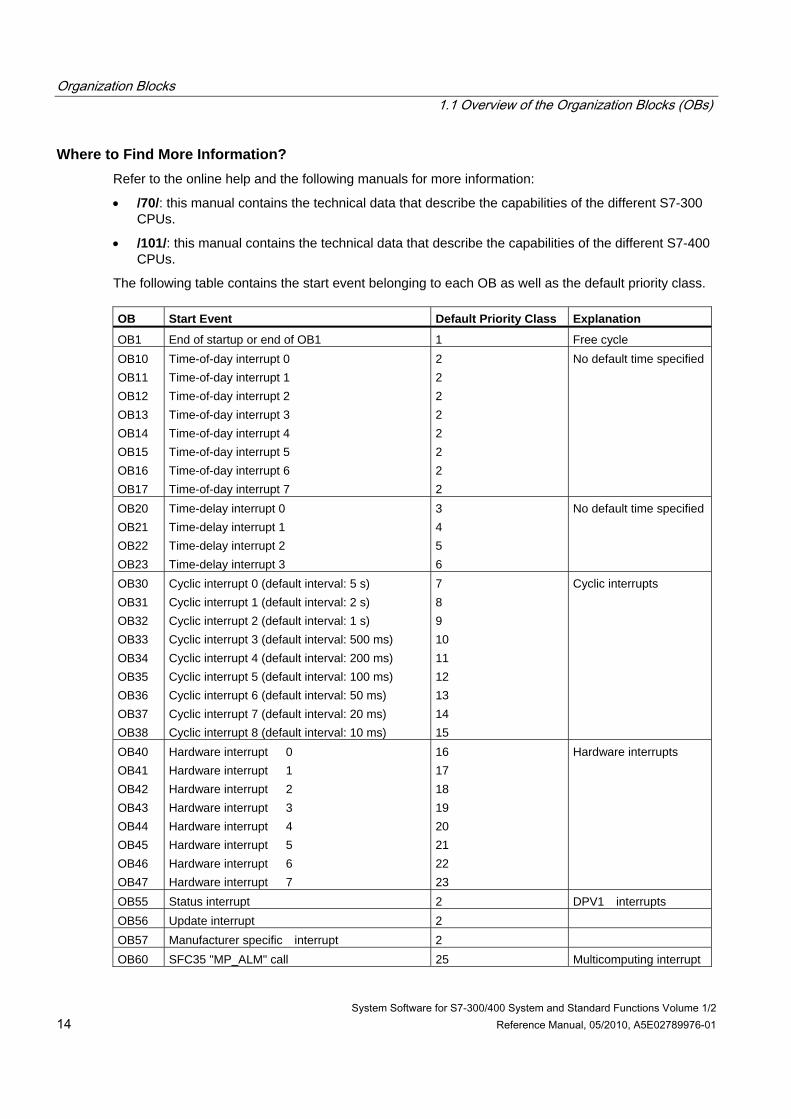
The following table contains the start event belonging to each OB as well as the default priority class. OB Start Event Default Priority Class Explanation
OB1 End of startup or end of OB1 1 Free cycle OB10 OB11 OB12 OB13 OB14 OB15 OB16 OB17
Time-of-day interrupt 0 Time-of-day interrupt 1 Time-of-day interrupt 2 Time-of-day interrupt 3 Time-of-day interrupt 4 Time-of-day interrupt 5 Time-of-day interrupt 6 Time-of-day interrupt 7
2 2 2 2 2 2 2 2
No default time specified
OB20 OB21 OB22 OB23
Time-delay interrupt 0 Time-delay interrupt 1 Time-delay interrupt 2 Time-delay interrupt 3
3 4 5 6
No default time specified
OB30 OB31 OB32 OB33 OB34 OB35 OB36 OB37 OB38
Cyclic interrupt 0 (default interval: 5 s) Cyclic interrupt 1 (default interval: 2 s) Cyclic interrupt 2 (default interval: 1 s) Cyclic interrupt 3 (default interval: 500 ms) Cyclic interrupt 4 (default interval: 200 ms) Cyclic interrupt 5 (default interval: 100 ms) Cyclic interrupt 6 (default interval: 50 ms) Cyclic interrupt 7 (default interval: 20 ms) Cyclic interrupt 8 (default interval: 10 ms)
7 8 9 10 11 12 13 14 15
Cyclic interrupts
OB40 OB41 OB42 OB43 OB44 OB45 OB46 OB47
Hardware interrupt 0 Hardware interrupt 1 Hardware interrupt 2 Hardware interrupt 3 Hardware interrupt 4 Hardware interrupt 5 Hardware interrupt 6 Hardware interrupt 7
16 17 18 19 20 21 22 23
Hardware interrupts
OB55 Status interrupt 2 DPV1 interrupts OB56 Update interrupt 2 OB57 Manufacturer specific interrupt 2 OB60 SFC35 "MP_ALM" call 25 Multicomputing interrupt

Organization Blocks 1.1 Overview of the Organization Blocks (OBs)
System Software for S7-300/400 System and Standard Functions Volume 1/2 Reference Manual, 05/2010, A5E02789976-01 15
OB Start Event Default Priority Class Explanation
OB61 OB62 OB63 OB64
Synchronous Cycle Interrupt 1 Synchronous Cycle Interrupt 2 Synchronous Cycle Interrupt 3 Synchronous Cycle Interrupt 4
25 25 25 25
Synchronous Cycle Interrupt
OB65 Technology synchronization interrupt 25 Technology synchronization interrupt
OB70 OB72 OB73
I/O redundancy error (only in H CPUs) CPU redundancy error (only in H CPUs) Communication redundancy error OB (only in H CPUs)
25 28 25
Redundancy error interrupts
OB80 Time error 26, 28 1) Asynchronous error interrupts
OB81
Power supply fault
26, 28 1) with S7-300, 25, 28 1) with S7-400 and CPU 318
OB82 Diagnostic interrupt 26, 28 1) with S7-300, 25, 28 1) with S7-400 and CPU 318
OB83
Insert/remove module interrupt
26, 28 1) with S7-300, 25, 28 1) with S7-400 and CPU 318
OB84
CPU hardware fault
26, 28 1) with S7-300, 25, 28 1) with S7-400 and CPU 318
OB85
Program error
26, 28 1) with S7-300, 25, 28 1) with S7-400 and CPU 318
OB86
Failure of an expansion rack, DP master system or station for distributed I/Os
26, 28 1) with S7-300, 25, 28 1) with S7-400 and CPU 318
OB87
Communication error
26, 28 1) with S7-300, 25, 28 1) with S7-400 and CPU 318
OB88 Processing interrupt 28 OB90 Warm or cold restart or delete a block being
executed in OB90 or load an OB90 on the CPU or terminate OB90
29 2) Background cycle
OB100 OB101 OB102
Warm restart Hot restart Cold restart
27 1)
27 1)
27 1)
Startup
OB121 OB122
Programming error I/O access error
Priority of the OB causing the error Priority of the OB causing the error
Synchronous error interrupts
1) Priority classes 27 and 28 are valid in the priority class model of the startup. 2) Priority class 29 corresponds to priority 0.29. This means that the background cycle has lower priority than the
free cycle.
Organization Blocks 1.2 Program Cycle Organization Block (OB1)
System Software for S7-300/400 System and Standard Functions Volume 1/2 16 Reference Manual, 05/2010, A5E02789976-01
1.2 Program Cycle Organization Block (OB1)
Description The operating system of the S7 CPU executes OB1 periodically. When OB1 has been executed, the operating system starts it again. Cyclic execution of OB1 is started after the startup has been completed. You can call other function blocks (FBs, SFBs) or functions (FCs, SFCs) in OB1.
Understanding the Operation of OB1 OB1 has the lowest priority of all of the OBs whose run-times are monitored, in other words, all of the other OBs except OB90 can interrupt the execution of OB1. The following events cause the operating system to call OB1:
• The startup is completed.
• The execution of OB1 (the previous cycle) has finished.
When OB1 has been executed, the operating system sends global data. Before restarting OB1, the operating system writes the process-image output table to the output modules, updates the process-image input table and receives any global data for the CPU.
S7 monitors the maximum scan time, ensuring a maximum response time. The value for the maximum scan time is preset to 150 ms. You can set a new value or you can restart the time monitoring anywhere within your program with SFC43 "RE_TRIGR." If your program exceeds the maximum cycle time for OB1, the operating system calls OB80 (time error OB); if OB80 is not programmed, the CPU changes to the STOP mode.
Apart from monitoring the maximum scan time, it is also possible to guarantee a minimum scan time. The operating system will delay the start of a new cycle (writing of the process image output table to the output modules) until the minimum scan time has been reached.
Refer to the manuals /70/ and /101/ for the ranges of the parameters "maximum" and "minimum" scan time. You change parameter settings using STEP 7.
Organization Blocks 1.2 Program Cycle Organization Block (OB1)
System Software for S7-300/400 System and Standard Functions Volume 1/2 Reference Manual, 05/2010, A5E02789976-01 17
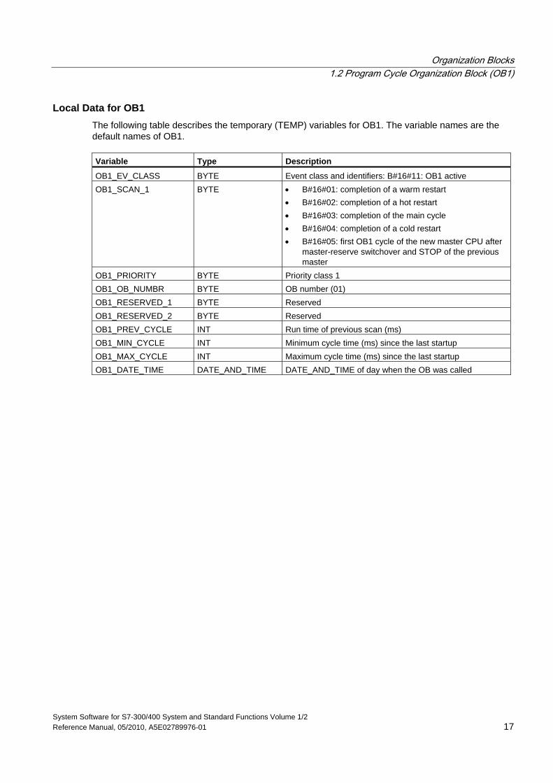
Local Data for OB1 The following table describes the temporary (TEMP) variables for OB1. The variable names are the default names of OB1. Variable Type Description
OB1_EV_CLASS BYTE Event class and identifiers: B#16#11: OB1 active OB1_SCAN_1 BYTE • B#16#01: completion of a warm restart
• B#16#02: completion of a hot restart • B#16#03: completion of the main cycle • B#16#04: completion of a cold restart • B#16#05: first OB1 cycle of the new master CPU after
master-reserve switchover and STOP of the previous master
OB1_PRIORITY BYTE Priority class 1 OB1_OB_NUMBR BYTE OB number (01) OB1_RESERVED_1 BYTE Reserved OB1_RESERVED_2 BYTE Reserved OB1_PREV_CYCLE INT Run time of previous scan (ms) OB1_MIN_CYCLE INT Minimum cycle time (ms) since the last startup OB1_MAX_CYCLE INT Maximum cycle time (ms) since the last startup OB1_DATE_TIME DATE_AND_TIME DATE_AND_TIME of day when the OB was called
Organization Blocks 1.3 Time-of-Day Interrupt Organization Blocks (OB10 to OB17)
System Software for S7-300/400 System and Standard Functions Volume 1/2 18 Reference Manual, 05/2010, A5E02789976-01
1.3 Time-of-Day Interrupt Organization Blocks (OB10 to OB17)
Description STEP 7 provides up to eight OBs (OB10 to OB17) which can be run once or periodically. You can assign parameters for CPU using SFCs or STEP 7 so that these OBs are processed at the following intervals:
• Once
• Every minute
• Hourly
• Daily
• Weekly
• Monthly
• At the end of each month
Note
For monthly execution of a time-of-day interrupt OBs, only the days 1, 2, ... 28 can be used as a starting date.
Organization Blocks 1.3 Time-of-Day Interrupt Organization Blocks (OB10 to OB17)
System Software for S7-300/400 System and Standard Functions Volume 1/2 Reference Manual, 05/2010, A5E02789976-01 19
Understanding the Operation of Time-of-Day Interrupt OBs To start a time-of-day interrupt, you must first set and then activate the interrupt. The three following start possibilities exist:
• Automatic start of the time-of-day interrupt. This occurs once you have set and then activated the time-of-day interrupt with STEP 7. The following table shows the basic possibilities for activating a time-of-day interrupt with STEP 7.
• You set the time-of-day interrupt with STEP 7 and then activate it by calling SFC30 "ACT-TINT" in your program.
• You set the time-of-day interrupt by calling SFC28 "SET_TINT" and then activate it by calling SFC30 "ACT_TINT."
Interval Description
Not activated The time-of-day interrupt is not executed, even when loaded in the CPU. It can be activated by calling SFC30.
Activated once only The time-of-day OB is canceled automatically after it runs the one time specified.
Your program can use SFC28 and SFC30 to reset and reactivate the OB.
Activated periodically When the time-of-day interrupt occurs, the CPU calculates the next start time for the time-of-day interrupt based on the current time of day and the period.
The behavior of the time-of-day interrupt when you move the clock forwards or backwards is described in /234/.
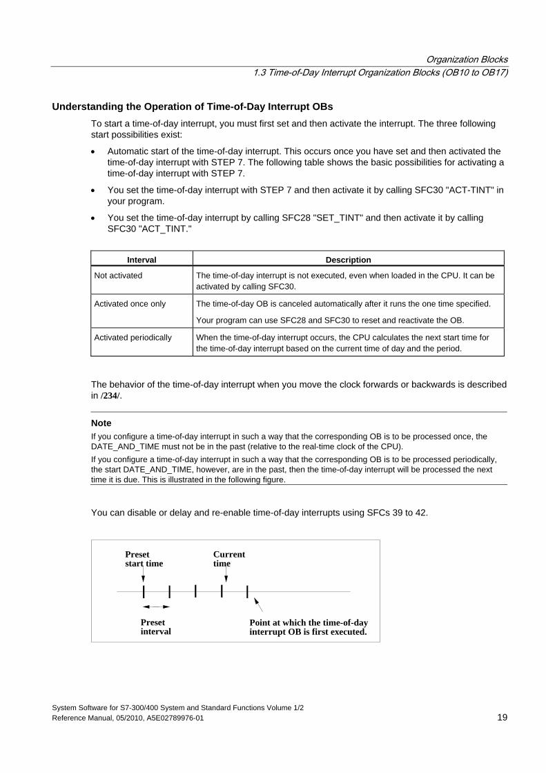
Note If you configure a time-of-day interrupt in such a way that the corresponding OB is to be processed once, the DATE_AND_TIME must not be in the past (relative to the real-time clock of the CPU). If you configure a time-of-day interrupt in such a way that the corresponding OB is to be processed periodically, the start DATE_AND_TIME, however, are in the past, then the time-of-day interrupt will be processed the next time it is due. This is illustrated in the following figure.
You can disable or delay and re-enable time-of-day interrupts using SFCs 39 to 42.
Presetstart time
Currenttime
Presetinterval
Point at which the time-of-dayinterrupt OB is first executed.
Organization Blocks 1.3 Time-of-Day Interrupt Organization Blocks (OB10 to OB17)
System Software for S7-300/400 System and Standard Functions Volume 1/2 20 Reference Manual, 05/2010, A5E02789976-01
Conditions That Affect Time-of-Day Interrupt OBs Since a time-of-day interrupt occurs only at specified intervals, certain conditions can affect the operation of the OB during the execution of your program. The following table shows some of these conditions and describes the effect on the execution of the time-of-day interrupt OB. Condition Result
Your program calls SFC29 (CAN_TINT) and cancels a time-of-day interrupt.
The operating system clears the start event (DATE_AND_TIME) for the time-of-day interrupt. You must set the start event again and activate it before the OB can be called again.
Your program attempted to activate a time-of-day interrupt OB, but the OB was not loaded on the CPU.
The operating system calls OB85. If OB85 has not been programmed (loaded on the CPU), the CPU changes to the STOP mode.
When synchronizing or correcting the system clock of the CPU, you set the time ahead and skipped the start event date or time for the time-of-day OB.
The operating system calls OB80 and encodes the number of the time-of-day OB and the start event information in OB80. The operating system then runs the time-of-day OB once, regardless of the number of times that this OB should have been executed. The start event information of OB80 shows the DATE_AND_TIME that the time-of-day OB was first skipped.
When synchronizing or correcting the system clock of the CPU, the time was set back so that the start event, date, or time for the OB is repeated.
S7-400-CPUs and CPU 318: If the time-of-day OB had already been activated before the clock was set back, it is not called again. S7-300-CPUs: The time-of-day OB is executed.
The CPU runs through a warm or cold restart. Any time-of-day OB that was configured by an SFC is changed back to the configuration that was specified in STEP 7. If you have configured a time-of-day interrupt for a one-time start of the corresponding OB, set it with STEP 7, and activated it, the OB is called once after a warm or cold restart of the operating system, if the configured start time is in the past (relative to the real-time clock of the CPU).
A time-of-day OB is still being executed when the start event for the next interval occurs.
The operating system calls OB80. If OB80 is not programmed, the CPU changes to the STOP mode. If OB80 is loaded, both OB80 and the time-of-day interrupt OB are first executed and then second the requested interrupt is executed.
Organization Blocks 1.3 Time-of-Day Interrupt Organization Blocks (OB10 to OB17)
System Software for S7-300/400 System and Standard Functions Volume 1/2 Reference Manual, 05/2010, A5E02789976-01 21
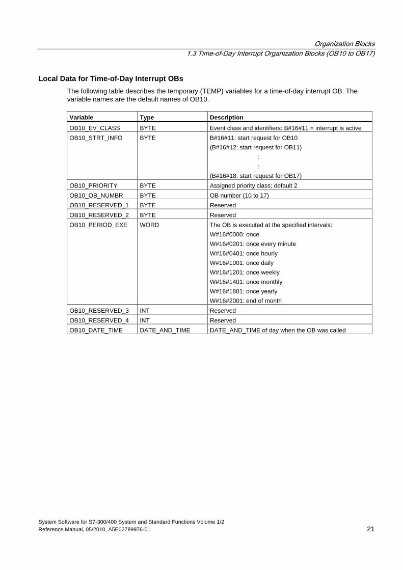
Local Data for Time-of-Day Interrupt OBs The following table describes the temporary (TEMP) variables for a time-of-day interrupt OB. The variable names are the default names of OB10. Variable Type Description
OB10_EV_CLASS BYTE Event class and identifiers: B#16#11 = interrupt is active OB10_STRT_INFO BYTE B#16#11: start request for OB10
(B#16#12: start request for OB11) : : (B#16#18: start request for OB17)
OB10_PRIORITY BYTE Assigned priority class; default 2 OB10_OB_NUMBR BYTE OB number (10 to 17) OB10_RESERVED_1 BYTE Reserved OB10_RESERVED_2 BYTE Reserved OB10_PERIOD_EXE WORD The OB is executed at the specified intervals:
W#16#0000: once W#16#0201: once every minute W#16#0401: once hourly W#16#1001: once daily W#16#1201: once weekly W#16#1401: once monthly W#16#1801: once yearly W#16#2001: end of month
OB10_RESERVED_3 INT Reserved OB10_RESERVED_4 INT Reserved OB10_DATE_TIME DATE_AND_TIME DATE_AND_TIME of day when the OB was called
Organization Blocks 1.4 Time-Delay Interrupt Organization Blocks (OB20 to OB23)
System Software for S7-300/400 System and Standard Functions Volume 1/2 22 Reference Manual, 05/2010, A5E02789976-01
1.4 Time-Delay Interrupt Organization Blocks (OB20 to OB23)
Description S7 provides up to four OBs (OB20 to OB23) which are executed after a specified delay. Every time-delay OB is started by calling SFC32 (SRT_DINT). The delay time is an input parameter of the SFC.
When your program calls SFC32 (SRT_DINT), you provide the OB number, the delay time, and a user-specific identifier. After the specified delay, the OB starts. You can also cancel the execution of a time-delay interrupt that has not yet started.
Understanding the Operation of Time-Delay Interrupt OBs After the delay time has expired (value in milliseconds transferred to SFC32 together with an OB number), the operating system starts the corresponding OB.
To use the time-delay interrupts, you must perform the following tasks:
• You must call SFC32 (SRT_DINT).
• You must download the time-delay interrupt OB to the CPU as part of your program.
Time-delay OBs are executed only when the CPU is in the RUN mode. A warm or a cold restart clears any start events for the time-delay OBs. If a time-delay interrupt has not started, you can use SFC33 (CAN_DINT) to cancel its execution.
The delay time has a resolution of 1 ms. A delay time that has expired can be started again immediately. You can query the status of a delay-time interrupt using SFC34 (QRY_DINT).
The operating system calls an asynchronous error OB if one of the following events occur:
• If the operating system attempts to start an OB that is not loaded and you specified its number when calling SFC32 "SRT_DINT."
• If the next start event for a time-delay interrupt occurs before the time-delay OB has been completely executed.
You can disable or delay and re-enable delay interrupts using SFCs 39 to 42.
Organization Blocks 1.4 Time-Delay Interrupt Organization Blocks (OB20 to OB23)
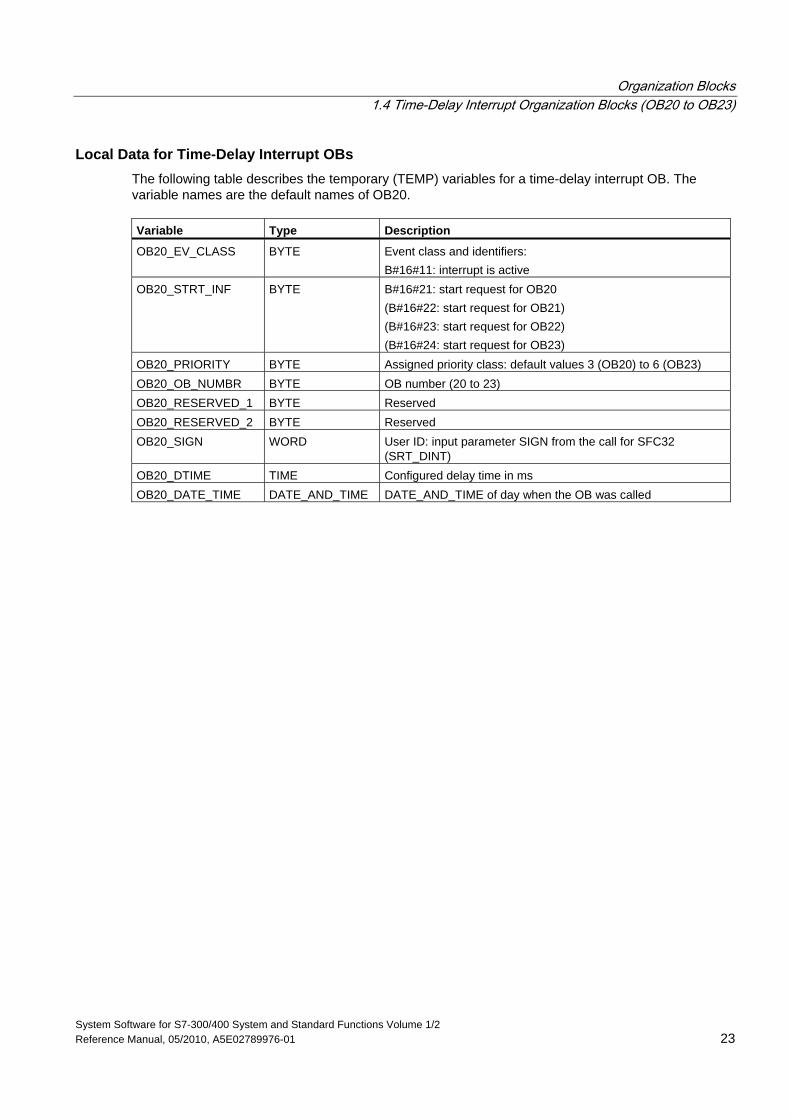
System Software for S7-300/400 System and Standard Functions Volume 1/2 Reference Manual, 05/2010, A5E02789976-01 23
Local Data for Time-Delay Interrupt OBs The following table describes the temporary (TEMP) variables for a time-delay interrupt OB. The variable names are the default names of OB20. Variable Type Description
OB20_EV_CLASS BYTE Event class and identifiers: B#16#11: interrupt is active
OB20_STRT_INF BYTE B#16#21: start request for OB20 (B#16#22: start request for OB21) (B#16#23: start request for OB22) (B#16#24: start request for OB23)
OB20_PRIORITY BYTE Assigned priority class: default values 3 (OB20) to 6 (OB23) OB20_OB_NUMBR BYTE OB number (20 to 23) OB20_RESERVED_1 BYTE Reserved OB20_RESERVED_2 BYTE Reserved OB20_SIGN WORD User ID: input parameter SIGN from the call for SFC32
(SRT_DINT) OB20_DTIME TIME Configured delay time in ms OB20_DATE_TIME DATE_AND_TIME DATE_AND_TIME of day when the OB was called
Organization Blocks 1.5 Cyclic Interrupt Organization Blocks (OB30 to OB38)
System Software for S7-300/400 System and Standard Functions Volume 1/2 24 Reference Manual, 05/2010, A5E02789976-01
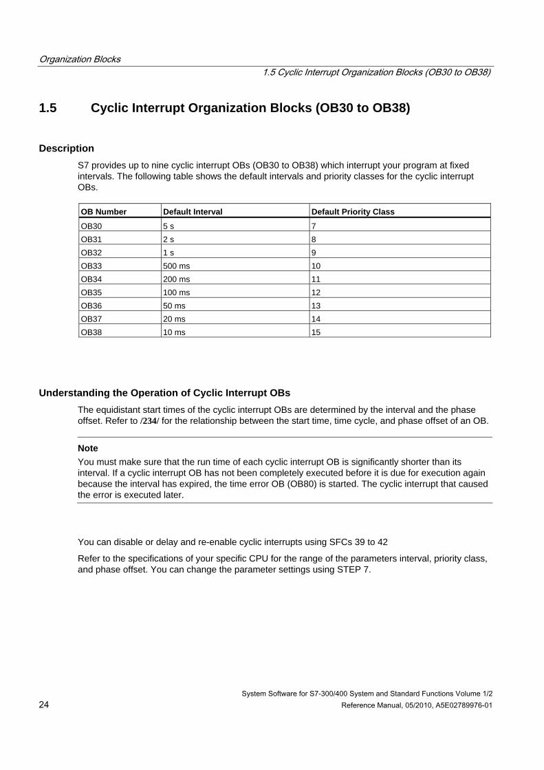
1.5 Cyclic Interrupt Organization Blocks (OB30 to OB38)
Description S7 provides up to nine cyclic interrupt OBs (OB30 to OB38) which interrupt your program at fixed intervals. The following table shows the default intervals and priority classes for the cyclic interrupt OBs. OB Number Default Interval Default Priority Class
OB30 5 s 7 OB31 2 s 8 OB32 1 s 9 OB33 500 ms 10 OB34 200 ms 11 OB35 100 ms 12 OB36 50 ms 13 OB37 20 ms 14 OB38 10 ms 15
Understanding the Operation of Cyclic Interrupt OBs The equidistant start times of the cyclic interrupt OBs are determined by the interval and the phase offset. Refer to /234/ for the relationship between the start time, time cycle, and phase offset of an OB.
Note You must make sure that the run time of each cyclic interrupt OB is significantly shorter than its interval. If a cyclic interrupt OB has not been completely executed before it is due for execution again because the interval has expired, the time error OB (OB80) is started. The cyclic interrupt that caused the error is executed later.
You can disable or delay and re-enable cyclic interrupts using SFCs 39 to 42
Refer to the specifications of your specific CPU for the range of the parameters interval, priority class, and phase offset. You can change the parameter settings using STEP 7.
Organization Blocks 1.5 Cyclic Interrupt Organization Blocks (OB30 to OB38)
System Software for S7-300/400 System and Standard Functions Volume 1/2 Reference Manual, 05/2010, A5E02789976-01 25
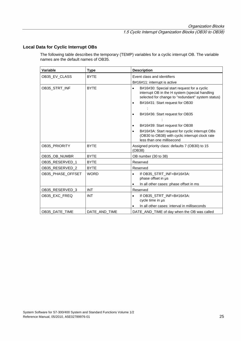
Local Data for Cyclic Interrupt OBs The following table describes the temporary (TEMP) variables for a cyclic interrupt OB. The variable names are the default names of OB35. Variable Type Description
OB35_EV_CLASS BYTE Event class and identifiers B#16#11: interrupt is active
OB35_STRT_INF BYTE • B#16#30: Special start request for a cyclic interrupt OB in the H system (special handling selected for change to "redundant" system status)
• B#16#31: Start request for OB30 : • B#16#36: Start request for OB35 : • B#16#39: Start request for OB38 • B#16#3A: Start request for cyclic interrupt OBs
(OB30 to OB38) with cyclic interrupt clock rate less than one millisecond
OB35_PRIORITY BYTE Assigned priority class: defaults 7 (OB30) to 15 (OB38)
OB35_OB_NUMBR BYTE OB number (30 to 38) OB35_RESERVED_1 BYTE Reserved OB35_RESERVED_2 BYTE Reserved OB35_PHASE_OFFSET WORD • If OB35_STRT_INF=B#16#3A:
phase offset in μs • In all other cases: phase offset in ms
OB35_RESERVED_3 INT Reserved OB35_EXC_FREQ INT • If OB35_STRT_INF=B#16#3A:
cycle time in μs • In all other cases: interval in milliseconds
OB35_DATE_TIME DATE_AND_TIME DATE_AND_TIME of day when the OB was called
Organization Blocks 1.6 Hardware Interrupt Organization Blocks (OB40 to OB47)
System Software for S7-300/400 System and Standard Functions Volume 1/2 26 Reference Manual, 05/2010, A5E02789976-01
1.6 Hardware Interrupt Organization Blocks (OB40 to OB47)
Description S7 provides up to eight independent hardware interrupts each with its own OB.
By assigning parameters with STEP 7, you specify the following for each signal module that will trigger hardware interrupts:
• Which channels trigger a hardware interrupt under what conditions.
• Which hardware interrupt OB is assigned to the individual groups of channels (as default, all hardware interrupts are processed by OB40).
With CPs and FMs, you assign these parameters using their own software.
You select the priority classes for the individual hardware interrupt OBs using STEP 7.
Understanding the Operation of Hardware Interrupt OBs After a hardware interrupt has been triggered by the module, the operating system identifies the slot and the corresponding hardware interrupt OB. If this OB has a higher priority than the currently active priority class, it will be started. The channel-specific acknowledgement is sent after this hardware interrupt OB has been executed.
If another event that triggers a hardware interrupt occurs on the same module during the time between identification and acknowledgement of a hardware interrupt, the following applies:
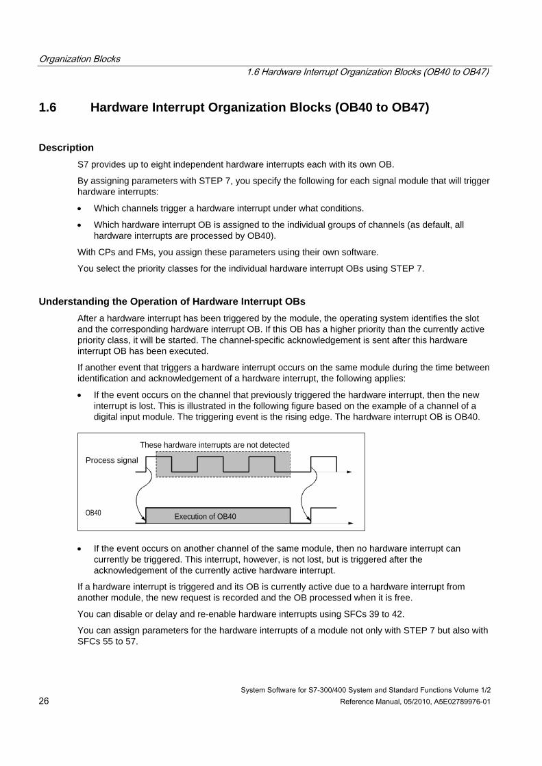
• If the event occurs on the channel that previously triggered the hardware interrupt, then the new interrupt is lost. This is illustrated in the following figure based on the example of a channel of a digital input module. The triggering event is the rising edge. The hardware interrupt OB is OB40.
Process signal
OB40 Execution of OB40
These hardware interrupts are not detected
• If the event occurs on another channel of the same module, then no hardware interrupt can currently be triggered. This interrupt, however, is not lost, but is triggered after the acknowledgement of the currently active hardware interrupt.
If a hardware interrupt is triggered and its OB is currently active due to a hardware interrupt from another module, the new request is recorded and the OB processed when it is free.
You can disable or delay and re-enable hardware interrupts using SFCs 39 to 42.
You can assign parameters for the hardware interrupts of a module not only with STEP 7 but also with SFCs 55 to 57.
Organization Blocks 1.6 Hardware Interrupt Organization Blocks (OB40 to OB47)
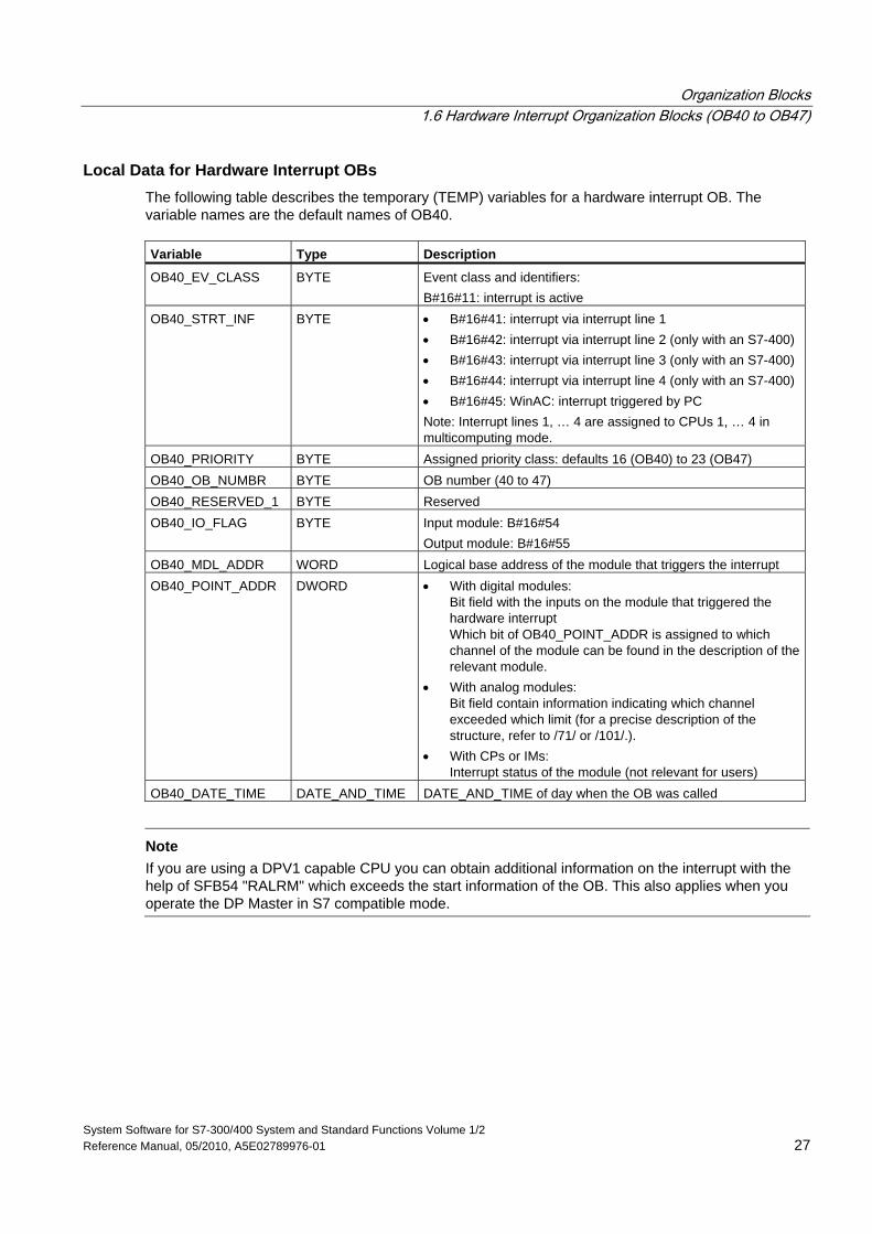
System Software for S7-300/400 System and Standard Functions Volume 1/2 Reference Manual, 05/2010, A5E02789976-01 27
Local Data for Hardware Interrupt OBs The following table describes the temporary (TEMP) variables for a hardware interrupt OB. The variable names are the default names of OB40. Variable Type Description
OB40_EV_CLASS BYTE Event class and identifiers: B#16#11: interrupt is active
OB40_STRT_INF BYTE • B#16#41: interrupt via interrupt line 1 • B#16#42: interrupt via interrupt line 2 (only with an S7-400) • B#16#43: interrupt via interrupt line 3 (only with an S7-400) • B#16#44: interrupt via interrupt line 4 (only with an S7-400) • B#16#45: WinAC: interrupt triggered by PC Note: Interrupt lines 1, … 4 are assigned to CPUs 1, … 4 in multicomputing mode.
OB40_PRIORITY BYTE Assigned priority class: defaults 16 (OB40) to 23 (OB47) OB40_OB_NUMBR BYTE OB number (40 to 47) OB40_RESERVED_1 BYTE Reserved OB40_IO_FLAG BYTE Input module: B#16#54
Output module: B#16#55 OB40_MDL_ADDR WORD Logical base address of the module that triggers the interrupt OB40_POINT_ADDR DWORD • With digital modules:
Bit field with the inputs on the module that triggered the hardware interrupt Which bit of OB40_POINT_ADDR is assigned to which channel of the module can be found in the description of the relevant module.
• With analog modules: Bit field contain information indicating which channel exceeded which limit (for a precise description of the structure, refer to /71/ or /101/.).
• With CPs or IMs: Interrupt status of the module (not relevant for users)
OB40_DATE_TIME DATE_AND_TIME DATE_AND_TIME of day when the OB was called
Note
If you are using a DPV1 capable CPU you can obtain additional information on the interrupt with the help of SFB54 "RALRM" which exceeds the start information of the OB. This also applies when you operate the DP Master in S7 compatible mode.
Organization Blocks 1.7 Status Interrupt OB (OB55)
System Software for S7-300/400 System and Standard Functions Volume 1/2 28 Reference Manual, 05/2010, A5E02789976-01
1.7 Status Interrupt OB (OB55)
Note
A status interrupt OB (OB55) is only available for DPV1 capable CPUs.
Description The CPU operating system calls OB55 if a status interrupt was triggered via the slot of a DPV1 slave. This might be the case if a component (module or rack) of a DPV1 slaves changes its operating mode, for example from RUN to STOP. For precise information on events that trigger a status interrupt, refer to the documentation of the DPV1 slave‘s manufacturer.
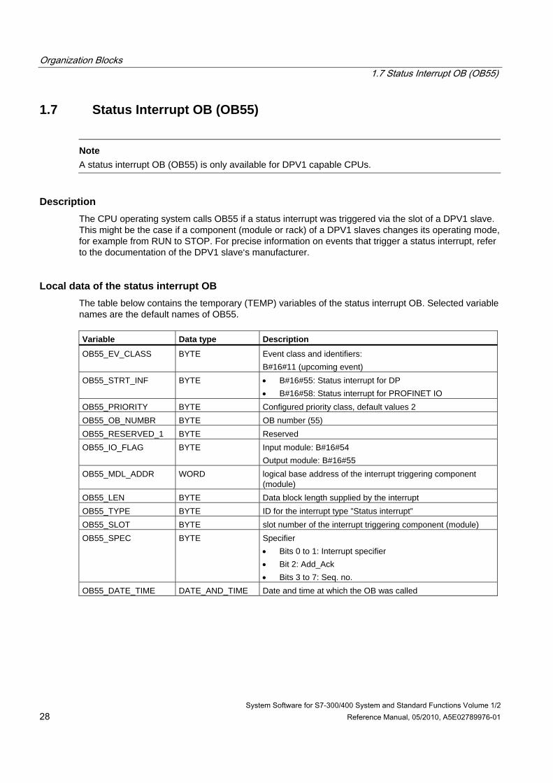
Local data of the status interrupt OB The table below contains the temporary (TEMP) variables of the status interrupt OB. Selected variable names are the default names of OB55. Variable Data type Description
OB55_EV_CLASS BYTE Event class and identifiers: B#16#11 (upcoming event)
OB55_STRT_INF BYTE • B#16#55: Status interrupt for DP • B#16#58: Status interrupt for PROFINET IO
OB55_PRIORITY BYTE Configured priority class, default values 2 OB55_OB_NUMBR BYTE OB number (55) OB55_RESERVED_1 BYTE Reserved OB55_IO_FLAG BYTE Input module: B#16#54
Output module: B#16#55 OB55_MDL_ADDR WORD logical base address of the interrupt triggering component
(module) OB55_LEN BYTE Data block length supplied by the interrupt OB55_TYPE BYTE ID for the interrupt type ”Status interrupt” OB55_SLOT BYTE slot number of the interrupt triggering component (module) OB55_SPEC BYTE Specifier
• Bits 0 to 1: Interrupt specifier • Bit 2: Add_Ack • Bits 3 to 7: Seq. no.
OB55_DATE_TIME DATE_AND_TIME Date and time at which the OB was called
Organization Blocks 1.7 Status Interrupt OB (OB55)
System Software for S7-300/400 System and Standard Functions Volume 1/2 Reference Manual, 05/2010, A5E02789976-01 29
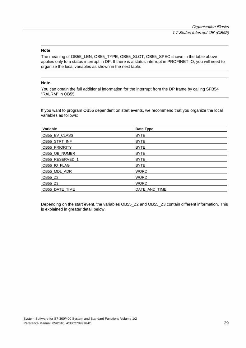
Note The meaning of OB55_LEN, OB55_TYPE, OB55_SLOT, OB55_SPEC shown in the table above applies only to a status interrupt in DP. If there is a status interrupt in PROFINET IO, you will need to organize the local variables as shown in the next table.
Note
You can obtain the full additional information for the interrupt from the DP frame by calling SFB54 "RALRM" in OB55.
If you want to program OB55 dependent on start events, we recommend that you organize the local variables as follows:
Variable Data Type
OB55_EV_CLASS BYTE OB55_STRT_INF BYTE OB55_PRIORITY BYTE OB55_OB_NUMBR BYTE OB55_RESERVED_1 BYTE_ OB55_IO_FLAG BYTE OB55_MDL_ADR WORD OB55_Z2 WORD OB55_Z3 WORD OB55_DATE_TIME DATE_AND_TIME
Depending on the start event, the variables OB55_Z2 and OB55_Z3 contain different information. This is explained in greater detail below.
Organization Blocks 1.7 Status Interrupt OB (OB55)
System Software for S7-300/400 System and Standard Functions Volume 1/2 30 Reference Manual, 05/2010, A5E02789976-01
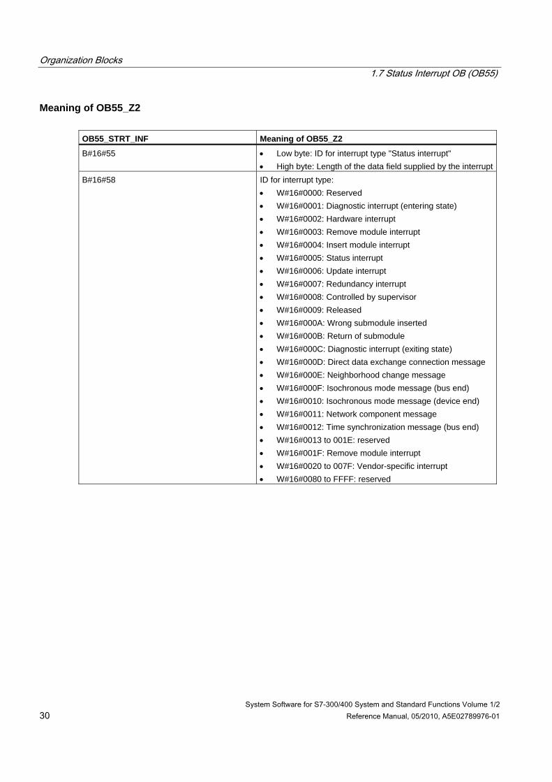
Meaning of OB55_Z2 OB55_STRT_INF Meaning of OB55_Z2
B#16#55 • Low byte: ID for interrupt type "Status interrupt" • High byte: Length of the data field supplied by the interrupt
B#16#58 ID for interrupt type: • W#16#0000: Reserved • W#16#0001: Diagnostic interrupt (entering state) • W#16#0002: Hardware interrupt • W#16#0003: Remove module interrupt • W#16#0004: Insert module interrupt • W#16#0005: Status interrupt • W#16#0006: Update interrupt • W#16#0007: Redundancy interrupt • W#16#0008: Controlled by supervisor • W#16#0009: Released • W#16#000A: Wrong submodule inserted • W#16#000B: Return of submodule • W#16#000C: Diagnostic interrupt (exiting state) • W#16#000D: Direct data exchange connection message • W#16#000E: Neighborhood change message • W#16#000F: Isochronous mode message (bus end) • W#16#0010: Isochronous mode message (device end) • W#16#0011: Network component message • W#16#0012: Time synchronization message (bus end) • W#16#0013 to 001E: reserved • W#16#001F: Remove module interrupt • W#16#0020 to 007F: Vendor-specific interrupt • W#16#0080 to FFFF: reserved
Organization Blocks 1.7 Status Interrupt OB (OB55)
System Software for S7-300/400 System and Standard Functions Volume 1/2 Reference Manual, 05/2010, A5E02789976-01 31
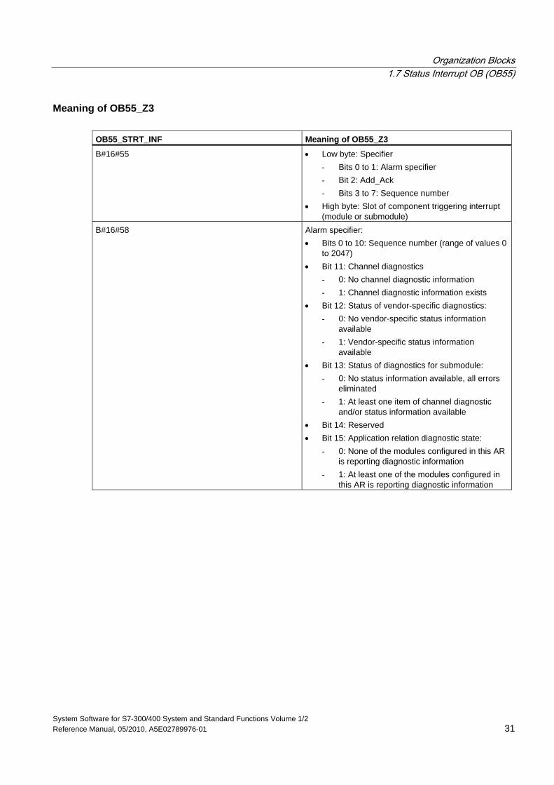
Meaning of OB55_Z3 OB55_STRT_INF Meaning of OB55_Z3
B#16#55 • Low byte: Specifier - Bits 0 to 1: Alarm specifier - Bit 2: Add_Ack - Bits 3 to 7: Sequence number
• High byte: Slot of component triggering interrupt (module or submodule)
B#16#58 Alarm specifier: • Bits 0 to 10: Sequence number (range of values 0
to 2047) • Bit 11: Channel diagnostics
- 0: No channel diagnostic information - 1: Channel diagnostic information exists
• Bit 12: Status of vendor-specific diagnostics: - 0: No vendor-specific status information
available - 1: Vendor-specific status information
available • Bit 13: Status of diagnostics for submodule:
- 0: No status information available, all errors eliminated
- 1: At least one item of channel diagnostic and/or status information available
• Bit 14: Reserved • Bit 15: Application relation diagnostic state:
- 0: None of the modules configured in this AR is reporting diagnostic information
- 1: At least one of the modules configured in this AR is reporting diagnostic information
Organization Blocks 1.8 Update Interrupt OB (OB56)
System Software for S7-300/400 System and Standard Functions Volume 1/2 32 Reference Manual, 05/2010, A5E02789976-01
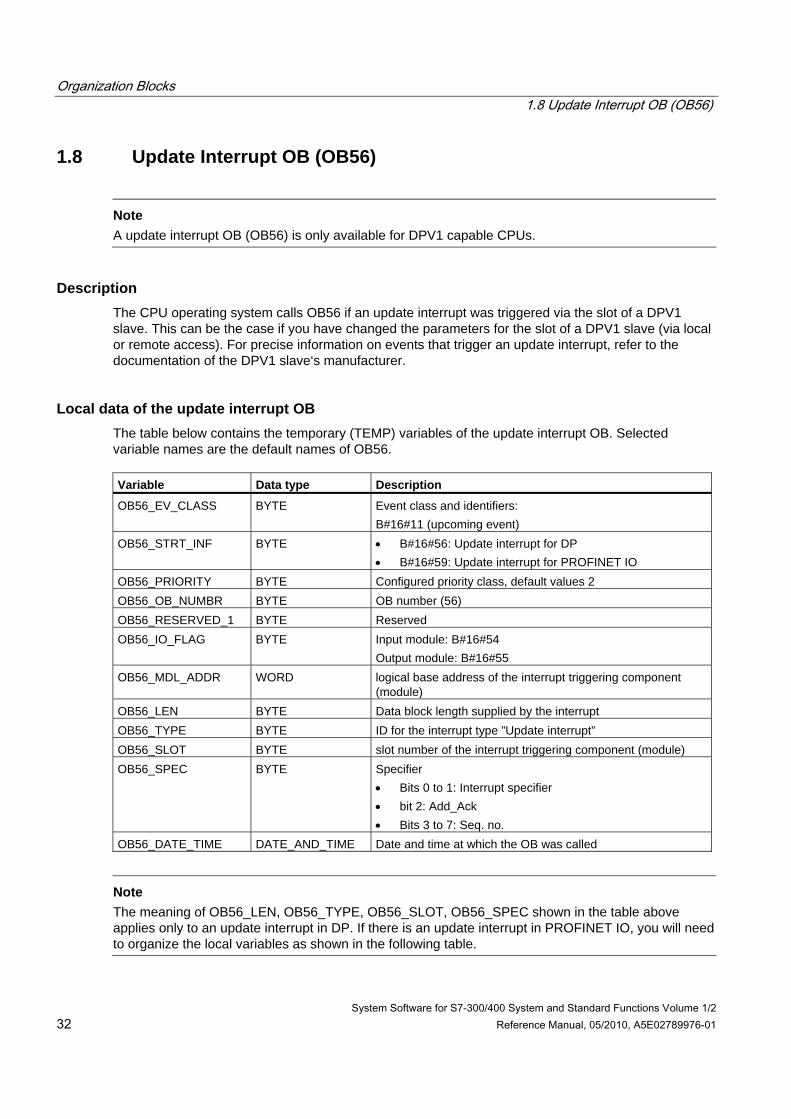
1.8 Update Interrupt OB (OB56)
Note
A update interrupt OB (OB56) is only available for DPV1 capable CPUs.
Description The CPU operating system calls OB56 if an update interrupt was triggered via the slot of a DPV1 slave. This can be the case if you have changed the parameters for the slot of a DPV1 slave (via local or remote access). For precise information on events that trigger an update interrupt, refer to the documentation of the DPV1 slave‘s manufacturer.
Local data of the update interrupt OB The table below contains the temporary (TEMP) variables of the update interrupt OB. Selected variable names are the default names of OB56. Variable Data type Description
OB56_EV_CLASS BYTE Event class and identifiers: B#16#11 (upcoming event)
OB56_STRT_INF BYTE • B#16#56: Update interrupt for DP • B#16#59: Update interrupt for PROFINET IO
OB56_PRIORITY BYTE Configured priority class, default values 2 OB56_OB_NUMBR BYTE OB number (56) OB56_RESERVED_1 BYTE Reserved OB56_IO_FLAG BYTE Input module: B#16#54
Output module: B#16#55 OB56_MDL_ADDR WORD logical base address of the interrupt triggering component
(module) OB56_LEN BYTE Data block length supplied by the interrupt OB56_TYPE BYTE ID for the interrupt type ”Update interrupt” OB56_SLOT BYTE slot number of the interrupt triggering component (module) OB56_SPEC BYTE Specifier
• Bits 0 to 1: Interrupt specifier • bit 2: Add_Ack • Bits 3 to 7: Seq. no.
OB56_DATE_TIME DATE_AND_TIME Date and time at which the OB was called
Note
The meaning of OB56_LEN, OB56_TYPE, OB56_SLOT, OB56_SPEC shown in the table above applies only to an update interrupt in DP. If there is an update interrupt in PROFINET IO, you will need to organize the local variables as shown in the following table.
Organization Blocks 1.8 Update Interrupt OB (OB56)
System Software for S7-300/400 System and Standard Functions Volume 1/2 Reference Manual, 05/2010, A5E02789976-01 33
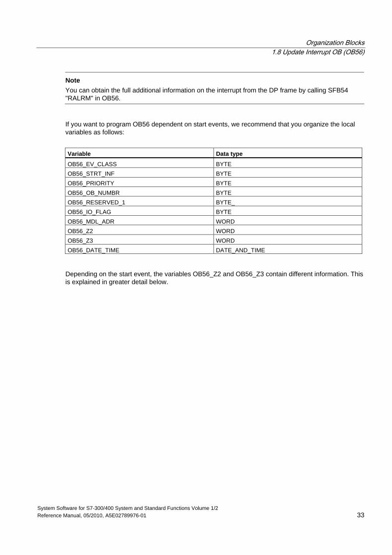
Note You can obtain the full additional information on the interrupt from the DP frame by calling SFB54 "RALRM" in OB56.
If you want to program OB56 dependent on start events, we recommend that you organize the local variables as follows:
Variable Data type
OB56_EV_CLASS BYTE OB56_STRT_INF BYTE OB56_PRIORITY BYTE OB56_OB_NUMBR BYTE OB56_RESERVED_1 BYTE_ OB56_IO_FLAG BYTE OB56_MDL_ADR WORD OB56_Z2 WORD OB56_Z3 WORD OB56_DATE_TIME DATE_AND_TIME
Depending on the start event, the variables OB56_Z2 and OB56_Z3 contain different information. This is explained in greater detail below.
Organization Blocks 1.8 Update Interrupt OB (OB56)
System Software for S7-300/400 System and Standard Functions Volume 1/2 34 Reference Manual, 05/2010, A5E02789976-01
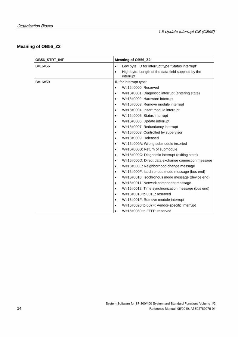
Meaning of OB56_Z2 OB56_STRT_INF Meaning of OB56_Z2
B#16#56 • Low byte: ID for interrupt type "Status interrupt" • High byte: Length of the data field supplied by the
interrupt B#16#59 ID for interrupt type:
• W#16#0000: Reserved • W#16#0001: Diagnostic interrupt (entering state) • W#16#0002: Hardware interrupt • W#16#0003: Remove module interrupt • W#16#0004: Insert module interrupt • W#16#0005: Status interrupt • W#16#0006: Update interrupt • W#16#0007: Redundancy interrupt • W#16#0008: Controlled by supervisor • W#16#0009: Released • W#16#000A: Wrong submodule inserted • W#16#000B: Return of submodule • W#16#000C: Diagnostic interrupt (exiting state) • W#16#000D: Direct data exchange connection message• W#16#000E: Neighborhood change message • W#16#000F: Isochronous mode message (bus end) • W#16#0010: Isochronous mode message (device end) • W#16#0011: Network component message • W#16#0012: Time synchronization message (bus end) • W#16#0013 to 001E: reserved • W#16#001F: Remove module interrupt • W#16#0020 to 007F: Vendor-specific interrupt • W#16#0080 to FFFF: reserved
Organization Blocks 1.8 Update Interrupt OB (OB56)
System Software for S7-300/400 System and Standard Functions Volume 1/2 Reference Manual, 05/2010, A5E02789976-01 35
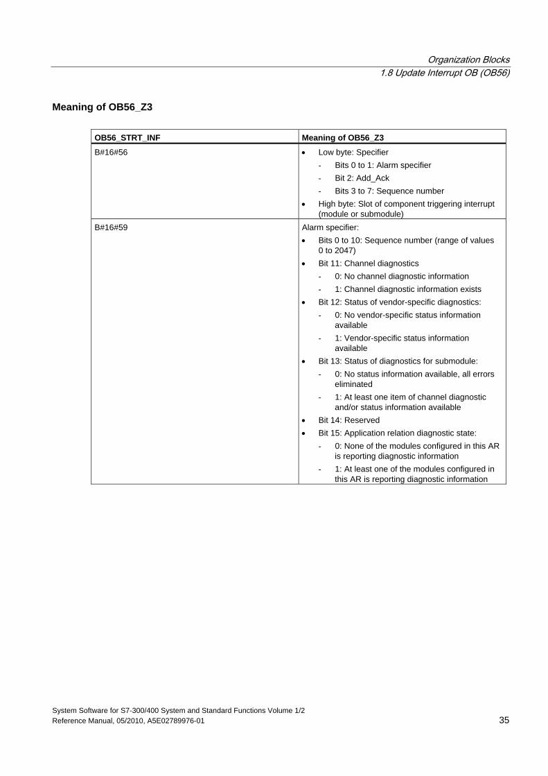
Meaning of OB56_Z3 OB56_STRT_INF Meaning of OB56_Z3
B#16#56 • Low byte: Specifier - Bits 0 to 1: Alarm specifier - Bit 2: Add_Ack - Bits 3 to 7: Sequence number
• High byte: Slot of component triggering interrupt (module or submodule)
B#16#59 Alarm specifier: • Bits 0 to 10: Sequence number (range of values
0 to 2047) • Bit 11: Channel diagnostics
- 0: No channel diagnostic information - 1: Channel diagnostic information exists
• Bit 12: Status of vendor-specific diagnostics: - 0: No vendor-specific status information
available - 1: Vendor-specific status information
available • Bit 13: Status of diagnostics for submodule:
- 0: No status information available, all errors eliminated
- 1: At least one item of channel diagnostic and/or status information available
• Bit 14: Reserved • Bit 15: Application relation diagnostic state:
- 0: None of the modules configured in this AR is reporting diagnostic information
- 1: At least one of the modules configured in this AR is reporting diagnostic information
Organization Blocks 1.9 Manufacturer Specific Interrupt OB (OB57)
System Software for S7-300/400 System and Standard Functions Volume 1/2 36 Reference Manual, 05/2010, A5E02789976-01
1.9 Manufacturer Specific Interrupt OB (OB57)
Note
An OB for manufacturer specific interrupts (OB57) is only available for DPV1 capable CPUs.
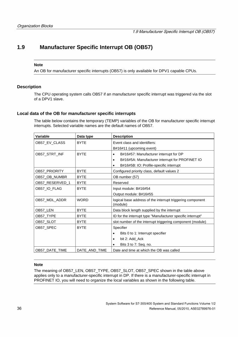
Description The CPU operating system calls OB57 if an manufacturer specific interrupt was triggered via the slot of a DPV1 slave.
Local data of the OB for manufacturer specific interrupts The table below contains the temporary (TEMP) variables of the OB for manufacturer specific interrupt interrupts. Selected variable names are the default names of OB57. Variable Data type Description
OB57_EV_CLASS BYTE Event class and identifiers: B#16#11 (upcoming event)
OB57_STRT_INF BYTE • B#16#57: Manufacturer interrupt for DP • B#16#5A: Manufacturer interrupt for PROFINET IO • B#16#5B: IO: Profile-specific interrupt
OB57_PRIORITY BYTE Configured priority class, default values 2 OB57_OB_NUMBR BYTE OB number (57) OB57_RESERVED_1 BYTE Reserved OB57_IO_FLAG BYTE Input module: B#16#54
Output module: B#16#55 OB57_MDL_ADDR WORD logical base address of the interrupt triggering component
(module) OB57_LEN BYTE Data block length supplied by the interrupt OB57_TYPE BYTE ID for the interrupt type ”Manufacturer specific interrupt” OB57_SLOT BYTE slot number of the interrupt triggering component (module) OB57_SPEC BYTE Specifier
• Bits 0 to 1: Interrupt specifier • bit 2: Add_Ack • Bits 3 to 7: Seq. no.
OB57_DATE_TIME DATE_AND_TIME Date and time at which the OB was called
Note
The meaning of OB57_LEN, OB57_TYPE, OB57_SLOT, OB57_SPEC shown in the table above applies only to a manufacturer-specific interrupt in DP. If there is a manufacturer-specific interrupt in PROFINET IO, you will need to organize the local variables as shown in the following table.
Organization Blocks 1.9 Manufacturer Specific Interrupt OB (OB57)
System Software for S7-300/400 System and Standard Functions Volume 1/2 Reference Manual, 05/2010, A5E02789976-01 37
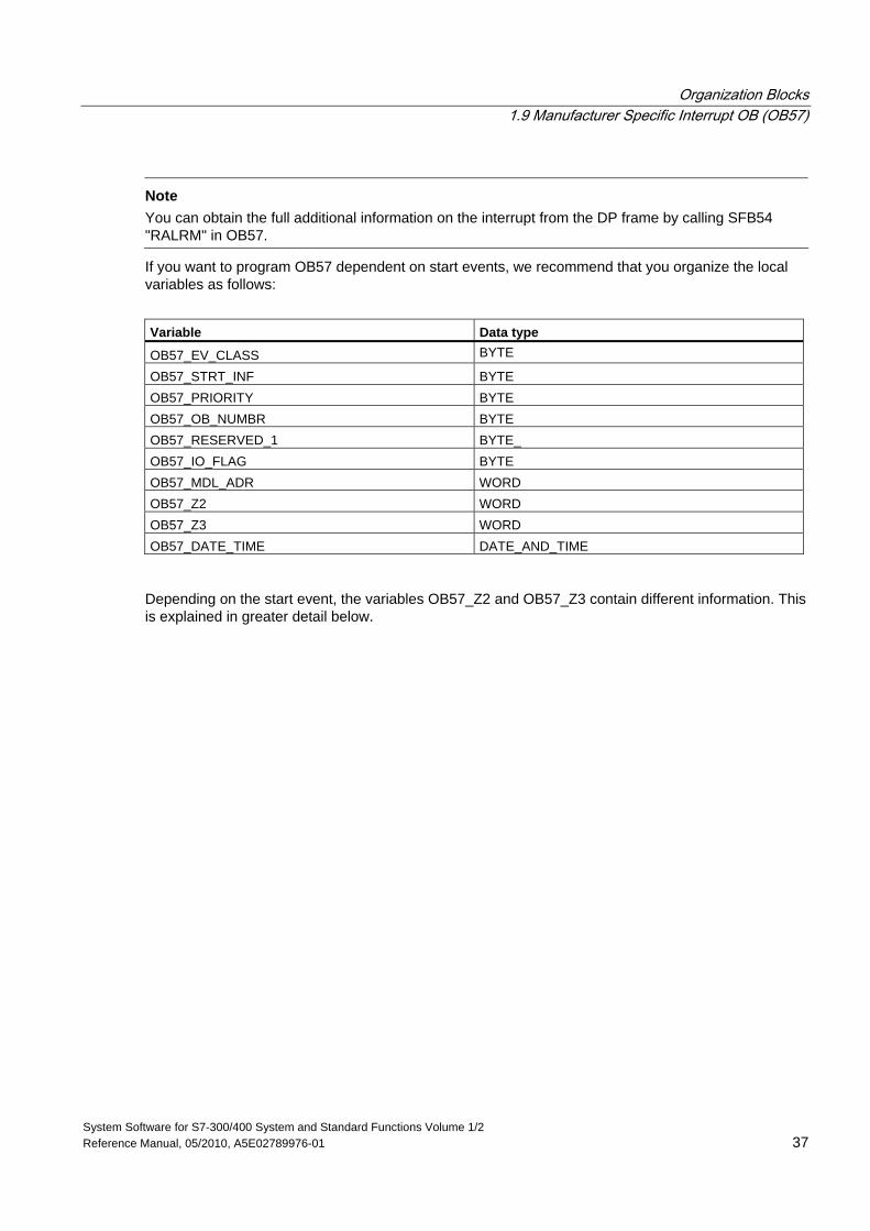
Note
You can obtain the full additional information on the interrupt from the DP frame by calling SFB54 "RALRM" in OB57.
If you want to program OB57 dependent on start events, we recommend that you organize the local variables as follows:
Variable Data type
OB57_EV_CLASS BYTE
OB57_STRT_INF BYTE OB57_PRIORITY BYTE OB57_OB_NUMBR BYTE OB57_RESERVED_1 BYTE_ OB57_IO_FLAG BYTE OB57_MDL_ADR WORD OB57_Z2 WORD OB57_Z3 WORD OB57_DATE_TIME DATE_AND_TIME
Depending on the start event, the variables OB57_Z2 and OB57_Z3 contain different information. This is explained in greater detail below.

Organization Blocks 1.9 Manufacturer Specific Interrupt OB (OB57)
System Software for S7-300/400 System and Standard Functions Volume 1/2 38 Reference Manual, 05/2010, A5E02789976-01
Meaning of OB57_Z2 OB57_STRT_INF Meaning of OB57_Z2
B#16#55 • Low byte: ID for interrupt type "Status interrupt" • High byte: Length of the data field supplied by the
interrupt B#16#58 ID for interrupt type:
• W#16#0000: Reserved • W#16#0001: Diagnostic interrupt (entering state) • W#16#0002: Hardware interrupt • W#16#0003: Remove module interrupt • W#16#0004: Insert module interrupt • W#16#0005: Status interrupt • W#16#0006: Update interrupt • W#16#0007: Redundancy interrupt • W#16#0008: Controlled by supervisor • W#16#0009: Released • W#16#000A: Wrong submodule inserted • W#16#000B: Return of submodule • W#16#000C: Diagnostic interrupt (exiting state) • W#16#000D: Direct data exchange connection message• W#16#000E: Neighborhood change message • W#16#000F: Isochronous mode message (bus end) • W#16#0010: Isochronous mode message (device end) • W#16#0011: Network component message • W#16#0012: Time synchronization message (bus end) • W#16#0013 to 001E: reserved • W#16#001F: Remove module interrupt • W#16#0020 to 007F: Vendor-specific interrupt • W#16#0080 to FFFF: reserved
Organization Blocks 1.9 Manufacturer Specific Interrupt OB (OB57)
System Software for S7-300/400 System and Standard Functions Volume 1/2 Reference Manual, 05/2010, A5E02789976-01 39
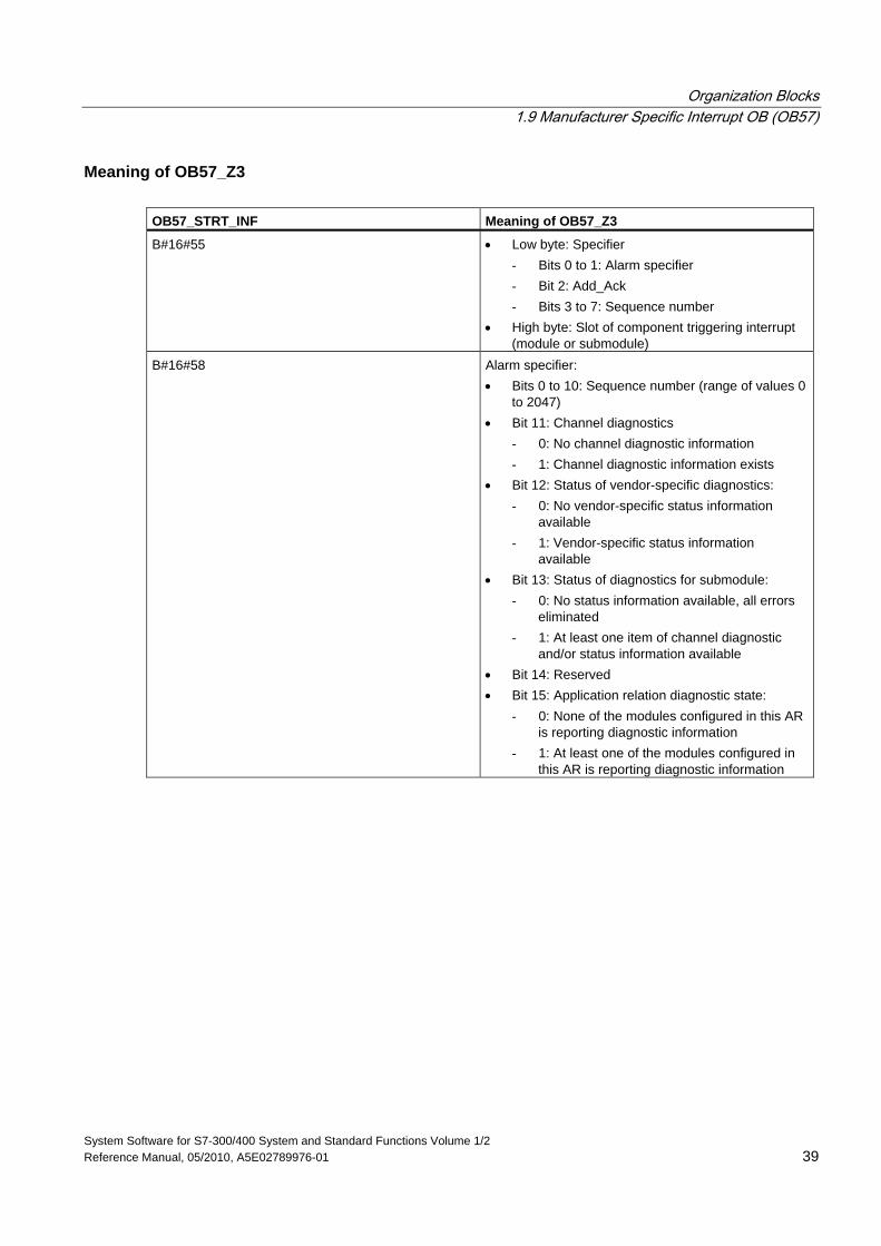
Meaning of OB57_Z3 OB57_STRT_INF Meaning of OB57_Z3
B#16#55 • Low byte: Specifier - Bits 0 to 1: Alarm specifier - Bit 2: Add_Ack - Bits 3 to 7: Sequence number
• High byte: Slot of component triggering interrupt (module or submodule)
B#16#58 Alarm specifier: • Bits 0 to 10: Sequence number (range of values 0
to 2047) • Bit 11: Channel diagnostics
- 0: No channel diagnostic information - 1: Channel diagnostic information exists
• Bit 12: Status of vendor-specific diagnostics: - 0: No vendor-specific status information
available - 1: Vendor-specific status information
available • Bit 13: Status of diagnostics for submodule:
- 0: No status information available, all errors eliminated
- 1: At least one item of channel diagnostic and/or status information available
• Bit 14: Reserved • Bit 15: Application relation diagnostic state:
- 0: None of the modules configured in this AR is reporting diagnostic information
- 1: At least one of the modules configured in this AR is reporting diagnostic information
Organization Blocks 1.10 Multicomputing Interrupt Organization Block (OB60)
System Software for S7-300/400 System and Standard Functions Volume 1/2 40 Reference Manual, 05/2010, A5E02789976-01
1.10 Multicomputing Interrupt Organization Block (OB60)
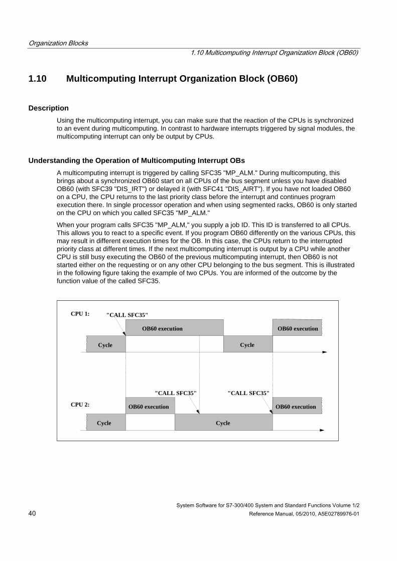
Description Using the multicomputing interrupt, you can make sure that the reaction of the CPUs is synchronized to an event during multicomputing. In contrast to hardware interrupts triggered by signal modules, the multicomputing interrupt can only be output by CPUs.
Understanding the Operation of Multicomputing Interrupt OBs A multicomputing interrupt is triggered by calling SFC35 "MP_ALM." During multicomputing, this brings about a synchronized OB60 start on all CPUs of the bus segment unless you have disabled OB60 (with SFC39 "DIS_IRT") or delayed it (with SFC41 "DIS_AIRT"). If you have not loaded OB60 on a CPU, the CPU returns to the last priority class before the interrupt and continues program execution there. In single processor operation and when using segmented racks, OB60 is only started on the CPU on which you called SFC35 "MP_ALM."
When your program calls SFC35 "MP_ALM," you supply a job ID. This ID is transferred to all CPUs. This allows you to react to a specific event. If you program OB60 differently on the various CPUs, this may result in different execution times for the OB. In this case, the CPUs return to the interrupted priority class at different times. If the next multicomputing interrupt is output by a CPU while another CPU is still busy executing the OB60 of the previous multicomputing interrupt, then OB60 is not started either on the requesting or on any other CPU belonging to the bus segment. This is illustrated in the following figure taking the example of two CPUs. You are informed of the outcome by the function value of the called SFC35.
CPU 1:
CPU 2:
Cycle
OB60 execution
OB60 execution OB60 execution
Cycle
OB60 execution
Cycle
Cycle
"CALL SFC35"
"CALL SFC35" "CALL SFC35"
Organization Blocks 1.10 Multicomputing Interrupt Organization Block (OB60)
System Software for S7-300/400 System and Standard Functions Volume 1/2 Reference Manual, 05/2010, A5E02789976-01 41
Local Data for Multicomputing Interrupt OBs The following table describes the temporary (TEMP) variables of the multicomputing interrupt OB. The variable names are the default names of OB60. Variable Data Type Description
OB60_EV_CLASS BYTE Event class and IDs: B#16#11: Interrupt is active
OB60_STRT_INF BYTE B#16#61: Multicomputing interrupt triggered by own CPU B#16#62: Multicomputing interrupt triggered by another CPU
OB60_PRIORITY BYTE Assigned Priority class: default 25 OB60_OB_NUMBR BYTE OB number: 60 OB60_RESERVED_1 BYTE Reserved OB60_RESERVED_2 BYTE Reserved OB60_JOB INT Job ID: input variable JOB of SFC35 "MP_ALM" OB60_RESERVED_3 INT Reserved OB60_RESERVED_4 INT Reserved OB60_DATE_TIME DATE_AND_TIME DATE_AND_TIME of day at which the OB was called.
Organization Blocks 1.11 Synchronous Cycle Interrupt OBs (OB61 to OB64)
System Software for S7-300/400 System and Standard Functions Volume 1/2 42 Reference Manual, 05/2010, A5E02789976-01
1.11 Synchronous Cycle Interrupt OBs (OB61 to OB64)
Description Synchronous cycle interrupts give you the option of starting programs in synchronous cycle with the DP cycle OR PN send clock. OB61 serves as an interface OB to the synchronous cycle interrupt TSAL1. You can set the priority for OB61 between 0 (OB deselected) and from 2 to 26.
! Caution For direct access with L or T commands (e.g. L PIB, T PQB) as well when using SFCs 14 "DPRD_DAT" and 15 "DPWR_DAT", avoid accessing I/O areas, whose process image partitions are assigned with a connection to OB6x (synchronous cycle interrupt)
Local Data for the Synchronous Cycle Interrupt OBs The following table describes the temporary (TEMP) variables of the synchronous cycle interrupt OBs. The variable names are the default names of OB61. Variable Data Type Description
OB61_EV_CLASS BYTE Event class and IDs: B#16#11: Interrupt is active
OB61_STRT_INF BYTE B#16#64: Start request for OB61 : B#16#67: Start request for OB64
OB61_PRIORITY BYTE Assigned Priority class; default: 25 OB61_OB_NUMBR BYTE OB number: 61 … 64 OB61_RESERVED_1 BYTE Reserved OB61_RESERVED_2 BYTE Reserved OB61_GC_VIOL BOOL GC violation in PROFIBUS DP OB61_FIRST BOOL First use after startup or stop status OB61_MISSED_EXEC BYTE Number of failed starts of OB61 since last execution of OB61OB61_DP_ID BYTE DP master system ID of the DP master system in
isochronous mode (1 to 32) or PROFINET IO system ID of the PNIO system in isochronous mode (100 to 115)
OB61_RESERVED_3 BYTE Reserved OB61_RESERVED_4 WORD Reserved OB61_DATE_TIME DATE_AND_TIME DATE_AND_TIME of day at which the OB was called.
Organization Blocks 1.12 Technology Synchronization Interrupt OB (OB65)
System Software for S7-300/400 System and Standard Functions Volume 1/2 Reference Manual, 05/2010, A5E02789976-01 43
1.12 Technology Synchronization Interrupt OB (OB65)
Note
The technology synchronization interrupt OB (OB65) only applies to Technology CPUs.
Description The technology synchronization interrupt provides the option of starting a program at the same time the technology blocks are updated. The technology synchronization interrupt OB is started after the technology blocks are updated.
The priority class of the technology synchronization interrupt OB is has a fixed setting of 25 and cannot be changed.
Note
At the time the technology synchronization interrupt OB is started there are still no updated instance data for the technology functions available.
Local Data for the Technology Synchronization Interrupt OB The following table describes the temporary (TEMP) variables of the technology synchronization interrupt OB65. The variable names are the default names of OB65. Variable Data Type Description
OB65_EV_CLASS BYTE Event class and IDs: B#16#11: incoming event, event class 1
OB65_STRT_INF BYTE B#16#6A: Start request for OB65 OB65_PRIORITY BYTE Priority class: 25 (fixed setting) OB65_OB_NUMBR BYTE OB number (65) OB65_RESERVED_1 BYTE Reserved OB65_RESERVED_2 BYTE Reserved OB65_RESERVED_3 BOOL Reserved OB65_FIRST BOOL First use of OB65 after startup OB65_MISSED_EXEC BYTE Number of failed starts of OB65 since last execution of
OB65 OB65_RESERVED_4 BYTE Reserved OB65_RESERVED_5 BYTE Reserved OB65_RESERVED_6 WORD Reserved OB65_DATE_TIME DATE_AND_TIME Date and time of day at which the OB was called.
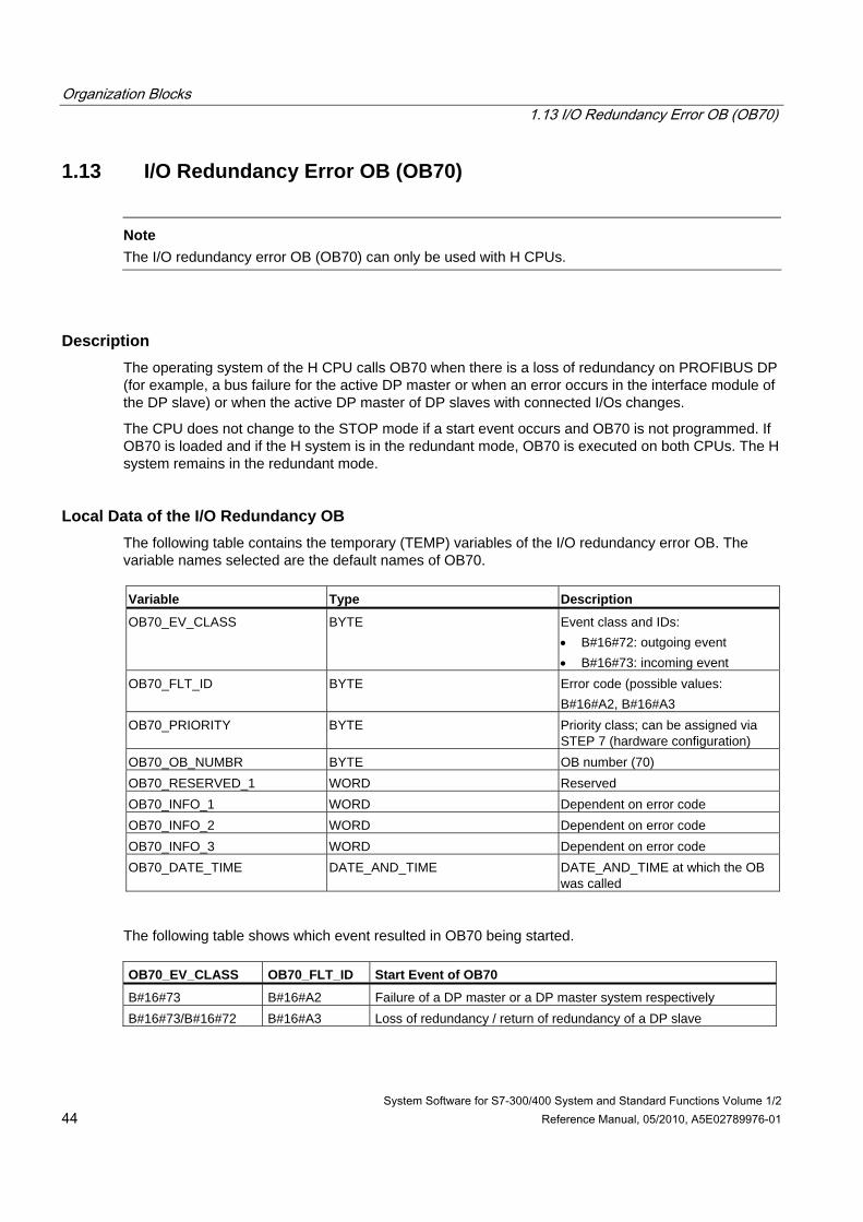
Organization Blocks 1.13 I/O Redundancy Error OB (OB70)
System Software for S7-300/400 System and Standard Functions Volume 1/2 44 Reference Manual, 05/2010, A5E02789976-01
1.13 I/O Redundancy Error OB (OB70)
Note
The I/O redundancy error OB (OB70) can only be used with H CPUs.
Description The operating system of the H CPU calls OB70 when there is a loss of redundancy on PROFIBUS DP (for example, a bus failure for the active DP master or when an error occurs in the interface module of the DP slave) or when the active DP master of DP slaves with connected I/Os changes.
The CPU does not change to the STOP mode if a start event occurs and OB70 is not programmed. If OB70 is loaded and if the H system is in the redundant mode, OB70 is executed on both CPUs. The H system remains in the redundant mode.
Local Data of the I/O Redundancy OB The following table contains the temporary (TEMP) variables of the I/O redundancy error OB. The variable names selected are the default names of OB70. Variable Type Description
OB70_EV_CLASS BYTE Event class and IDs: • B#16#72: outgoing event • B#16#73: incoming event
OB70_FLT_ID BYTE Error code (possible values: B#16#A2, B#16#A3
OB70_PRIORITY BYTE Priority class; can be assigned via STEP 7 (hardware configuration)
OB70_OB_NUMBR BYTE OB number (70) OB70_RESERVED_1 WORD Reserved OB70_INFO_1 WORD Dependent on error code OB70_INFO_2 WORD Dependent on error code OB70_INFO_3 WORD Dependent on error code OB70_DATE_TIME DATE_AND_TIME DATE_AND_TIME at which the OB
was called
The following table shows which event resulted in OB70 being started. OB70_EV_CLASS OB70_FLT_ID Start Event of OB70
B#16#73 B#16#A2 Failure of a DP master or a DP master system respectively B#16#73/B#16#72 B#16#A3 Loss of redundancy / return of redundancy of a DP slave
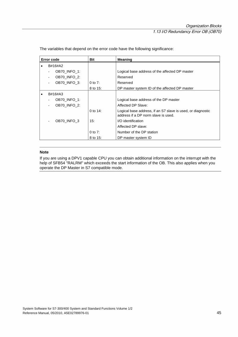
Organization Blocks 1.13 I/O Redundancy Error OB (OB70)
System Software for S7-300/400 System and Standard Functions Volume 1/2 Reference Manual, 05/2010, A5E02789976-01 45
The variables that depend on the error code have the following significance: Error code Bit Meaning
• B#16#A2 - OB70_INFO_1: - OB70_INFO_2: - OB70_INFO_3:
0 to 7: 8 to 15:
Logical base address of the affected DP master Reserved Reserved DP master system ID of the affected DP master
• B#16#A3 - OB70_INFO_1: - OB70_INFO_2:
- OB70_INFO_3
0 to 14: 15: 0 to 7: 8 to 15:
Logical base address of the DP master Affected DP Slave: Logical base address, if an S7 slave is used, or diagnostic address if a DP norm slave is used. I/O identification Affected DP slave: Number of the DP station DP master system ID
Note
If you are using a DPV1 capable CPU you can obtain additional information on the interrupt with the help of SFB54 "RALRM" which exceeds the start information of the OB. This also applies when you operate the DP Master in S7 compatible mode.
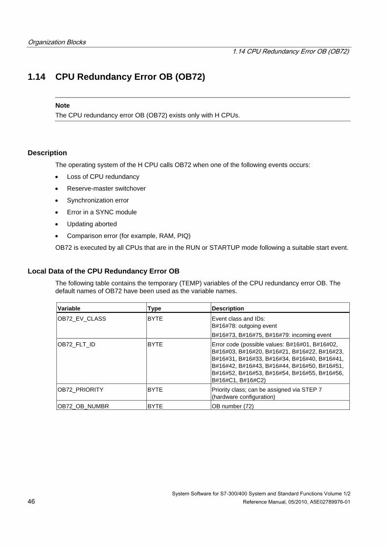
Organization Blocks 1.14 CPU Redundancy Error OB (OB72)
System Software for S7-300/400 System and Standard Functions Volume 1/2 46 Reference Manual, 05/2010, A5E02789976-01
1.14 CPU Redundancy Error OB (OB72)
Note
The CPU redundancy error OB (OB72) exists only with H CPUs.
Description The operating system of the H CPU calls OB72 when one of the following events occurs:
• Loss of CPU redundancy
• Reserve-master switchover
• Synchronization error
• Error in a SYNC module
• Updating aborted
• Comparison error (for example, RAM, PIQ)
OB72 is executed by all CPUs that are in the RUN or STARTUP mode following a suitable start event.
Local Data of the CPU Redundancy Error OB The following table contains the temporary (TEMP) variables of the CPU redundancy error OB. The default names of OB72 have been used as the variable names. Variable Type Description
OB72_EV_CLASS BYTE Event class and IDs: B#16#78: outgoing event B#16#73, B#16#75, B#16#79: incoming event
OB72_FLT_ID BYTE Error code (possible values: B#16#01, B#16#02, B#16#03, B#16#20, B#16#21, B#16#22, B#16#23, B#16#31, B#16#33, B#16#34, B#16#40, B#16#41, B#16#42, B#16#43, B#16#44, B#16#50, B#16#51, B#16#52, B#16#53, B#16#54, B#16#55, B#16#56, B#16#C1, B#16#C2)
OB72_PRIORITY BYTE Priority class; can be assigned via STEP 7 (hardware configuration)
OB72_OB_NUMBR BYTE OB number (72)
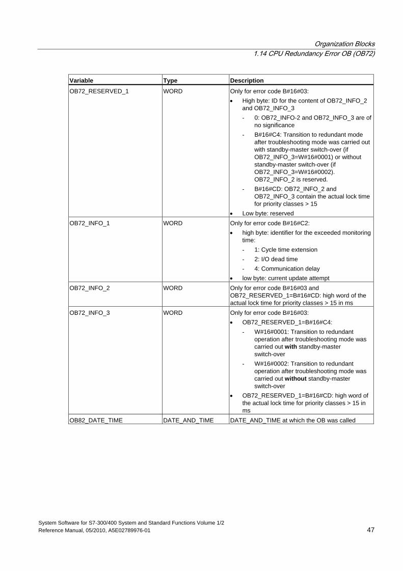
Organization Blocks 1.14 CPU Redundancy Error OB (OB72)
System Software for S7-300/400 System and Standard Functions Volume 1/2 Reference Manual, 05/2010, A5E02789976-01 47
Variable Type Description
OB72_RESERVED_1 WORD Only for error code B#16#03: • High byte: ID for the content of OB72_INFO_2
and OB72_INFO_3 - 0: OB72_INFO-2 and OB72_INFO_3 are of
no significance - B#16#C4: Transition to redundant mode
after troubleshooting mode was carried out with standby-master switch-over (if OB72_INFO_3=W#16#0001) or without standby-master switch-over (if OB72_INFO_3=W#16#0002). OB72_INFO_2 is reserved.
- B#16#CD: OB72_INFO_2 and OB72_INFO_3 contain the actual lock time for priority classes > 15
• Low byte: reserved OB72_INFO_1 WORD Only for error code B#16#C2:
• high byte: identifier for the exceeded monitoring time: - 1: Cycle time extension - 2: I/O dead time - 4: Communication delay
• low byte: current update attempt OB72_INFO_2 WORD Only for error code B#16#03 and
OB72_RESERVED_1=B#16#CD: high word of the actual lock time for priority classes > 15 in ms
OB72_INFO_3 WORD Only for error code B#16#03: • OB72_RESERVED_1=B#16#C4:
- W#16#0001: Transition to redundant operation after troubleshooting mode was carried out with standby-master switch-over
- W#16#0002: Transition to redundant operation after troubleshooting mode was carried out without standby-master switch-over
• OB72_RESERVED_1=B#16#CD: high word of the actual lock time for priority classes > 15 in ms
OB82_DATE_TIME DATE_AND_TIME DATE_AND_TIME at which the OB was called
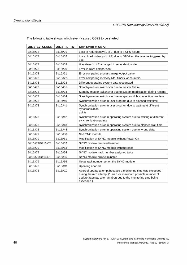
Organization Blocks 1.14 CPU Redundancy Error OB (OB72)
System Software for S7-300/400 System and Standard Functions Volume 1/2 48 Reference Manual, 05/2010, A5E02789976-01
The following table shows which event caused OB72 to be started. OB72_EV_CLASS OB72_FLT_ID Start Event of OB72
B#16#73 B#16#01 Loss of redundancy (1 of 2) due to a CPU failure B#16#73 B#16#02 Loss of redundancy (1 of 2) due to STOP on the reserve triggered by
user B#16#73 B#16#03 H system (1 of 2) changed to redundant mode B#16#73 B#16#20 Error in RAM comparison B#16#73 B#16#21 Error comparing process image output value B#16#73 B#16#22 Error comparing memory bits, timers, or counters B#16#73 B#16#23 Different operating system data recognized B#16#73 B#16#31 Standby-master switchover due to master failure B#16#73 B#16#33 Standby-master switchover due to system modification during runtime B#16#73 B#16#34 Standby-master switchover due to sync module connection problem B#16#73 B#16#40 Synchronization error in user program due to elapsed wait time B#16#73 B#16#41 Synchronization error in user program due to waiting at different
synchronization points
B#16#73 B#16#42 Synchronization error in operating system due to waiting at different synchronization points
B#16#73 B#16#43 Synchronization error in operating system due to elapsed wait time B#16#73 B#16#44 Synchronization error in operating system due to wrong data B#16#79 B#16#50 No SYNC module B#16#79 B#16#51 Modification at SYNC module without Power On B#16#79/B#16#78 B#16#52 SYNC module removed/inserted B#16#79 B#16#53 Modification at SYNC module without reset B#16#79 B#16#54 SYNC module: rack number assigned twice B#16#79/B#16#78 B#16#55 SYNC module error/eliminated B#16#79 B#16#56 Illegal rack number set on the SYNC module B#16#73 B#16#C1 Updating aborted B#16#73 B#16#C2 Abort of update attempt because a monitoring time was exceeded
during the n-th attempt (1 <= n <= maximum possible number of update attempts after an abort due to the monitoring time being exceeded.)
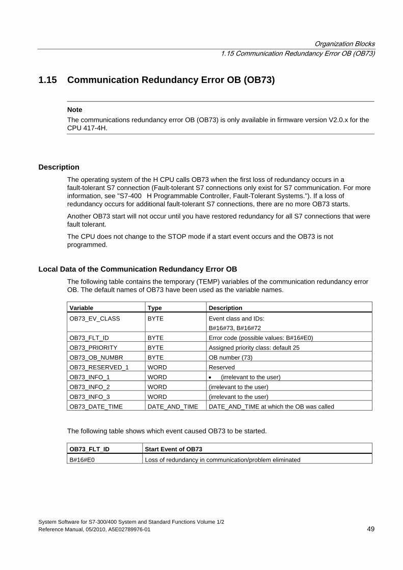
Organization Blocks 1.15 Communication Redundancy Error OB (OB73)
System Software for S7-300/400 System and Standard Functions Volume 1/2 Reference Manual, 05/2010, A5E02789976-01 49
1.15 Communication Redundancy Error OB (OB73)
Note
The communications redundancy error OB (OB73) is only available in firmware version V2.0.x for the CPU 417-4H.
Description The operating system of the H CPU calls OB73 when the first loss of redundancy occurs in a fault-tolerant S7 connection (Fault-tolerant S7 connections only exist for S7 communication. For more information, see "S7-400 H Programmable Controller, Fault-Tolerant Systems."). If a loss of redundancy occurs for additional fault-tolerant S7 connections, there are no more OB73 starts.
Another OB73 start will not occur until you have restored redundancy for all S7 connections that were fault tolerant.
The CPU does not change to the STOP mode if a start event occurs and the OB73 is not programmed.
Local Data of the Communication Redundancy Error OB The following table contains the temporary (TEMP) variables of the communication redundancy error OB. The default names of OB73 have been used as the variable names. Variable Type Description
OB73_EV_CLASS BYTE Event class and IDs: B#16#73, B#16#72
OB73_FLT_ID BYTE Error code (possible values: B#16#E0) OB73_PRIORITY BYTE Assigned priority class: default 25 OB73_OB_NUMBR BYTE OB number (73) OB73_RESERVED_1 WORD Reserved OB73_INFO_1 WORD • (irrelevant to the user) OB73_INFO_2 WORD (irrelevant to the user) OB73_INFO_3 WORD (irrelevant to the user) OB73_DATE_TIME DATE_AND_TIME DATE_AND_TIME at which the OB was called
The following table shows which event caused OB73 to be started. OB73_FLT_ID Start Event of OB73
B#16#E0 Loss of redundancy in communication/problem eliminated

Organization Blocks 1.16 Time Error Organization Block (OB80)
System Software for S7-300/400 System and Standard Functions Volume 1/2 50 Reference Manual, 05/2010, A5E02789976-01
1.16 Time Error Organization Block (OB80)
Description The operating system of the S7-300 CPU calls OB80 whenever an error occurs while executing an OB. Such errors include: exceeding the cycle time, an acknowledgement error when executing an OB, moving the time forward so that the start time for the OB is skipped, resume RUN mode after CiR. If, for example, a start event for a cyclic interrupt OB occurs while the same OB is still being executed following a previous call, the operating system calls OB80.
If OB80 has not been programmed, the CPU changes to the STOP mode.
You can disable or delay and re-enable the time error OB using SFCs 39 to 42.
Note If OB80 is called twice during the same scan cycle due to the scan time being exceeded, the CPU changes to the STOP mode. You can prevent this by calling SFC43 "RE_TRIGR" at a suitable point in the program.
Local Data for the Time Error OB The following table describes the temporary (TEMP) variables for the time error OB. The variable names are the default names of OB80. Variable Type Description
OB80_EV_CLASS BYTE Event class and identifiers: B#16#35 OB80_FLT_ID BYTE Error code: (possible values:
B#16#01, B#16#02, B#16#05, B#16#06, B#16#07, B#16#08, B#16#09, B#16#0A, B#16#0B)
OB80_PRIORITY BYTE Priority class: OB 80 runs with priority class 26 in RUN mode, and in the event of an overflow of the OB request buffer with priority class 28
OB80_OB_NUMBR BYTE OB number (80) OB80_RESERVED_1 BYTE Reserved OB80_RESERVED_2 BYTE Reserved OB80_ERROR_INFO WORD Error information: depending on error code OB80_ERR_EV_CLASS BYTE Event class for the start event that caused the error OB80_ERR_EV_NUM BYTE Event number for the start event that caused the error OB80_OB_PRIORITY BYTE Error information: depending on error code OB80_OB_NUM BYTE Error information: depending on error code OB80_DATE_TIME DATE_AND_TIME DATE_AND_TIME of day when the OB was called
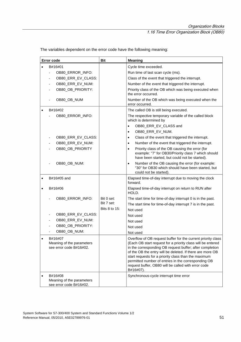
Organization Blocks 1.16 Time Error Organization Block (OB80)
System Software for S7-300/400 System and Standard Functions Volume 1/2 Reference Manual, 05/2010, A5E02789976-01 51
The variables dependent on the error code have the following meaning: Error code Bit Meaning
• B#16#01 - OB80_ERROR_INFO: - OB80_ERR_EV_CLASS: - OB80_ERR_EV_NUM: - OB80_OB_PRIORITY:
- OB80_OB_NUM
Cycle time exceeded. Run time of last scan cycle (ms). Class of the event that triggered the interrupt. Number of the event that triggered the interrupt. Priority class of the OB which was being executed when the error occurred. Number of the OB which was being executed when the error occurred.
• B#16#02 - OB80_ERROR_INFO:
- OB80_ERR_EV_CLASS: - OB80_ERR_EV_NUM: - OB80_OB_PRIORITY
- OB80_OB_NUM:
The called OB is still being executed. The respective temporary variable of the called block which is determined by • OB80_ERR_EV_CLASS and • OB80_ERR_EV_NUM. • Class of the event that triggered the interrupt. • Number of the event that triggered the interrupt. • Priority class of the OB causing the error (for
example: "7” for OB30/Priority class 7 which should have been started, but could not be started).
• Number of the OB causing the error (for example: "30” for OB30 which should have been started, but could not be started).
• B#16#05 and
• B#16#06 - OB80_ERROR_INFO:
- OB80_ERR_EV_CLASS: - OB80_ERR_EV_NUM: - OB80_OB_PRIORITY: - OB80_OB_NUM:
Bit 0 set: Bit 7 set: Bits 8 to 15:
Elapsed time-of-day interrupt due to moving the clock forward. Elapsed time-of-day interrupt on return to RUN after HOLD. The start time for time-of-day interrupt 0 is in the past. The start time for time-of-day interrupt 7 is in the past. Not used Not used Not used Not used Not used
• B#16#07 Meaning of the parameters see error code B#16#02.
Overflow of OB request buffer for the current priority class(Each OB start request for a priority class will be entered in the corresponding OB request buffer; after completion of the OB the entry will be deleted. If there are more OB start requests for a priority class than the maximum permitted number of entries in the corresponding OB request buffer, OB80 will be called with error code B#16#07).
• B#16#08 Meaning of the parameters see error code B#16#02.
Synchronous-cycle interrupt time error
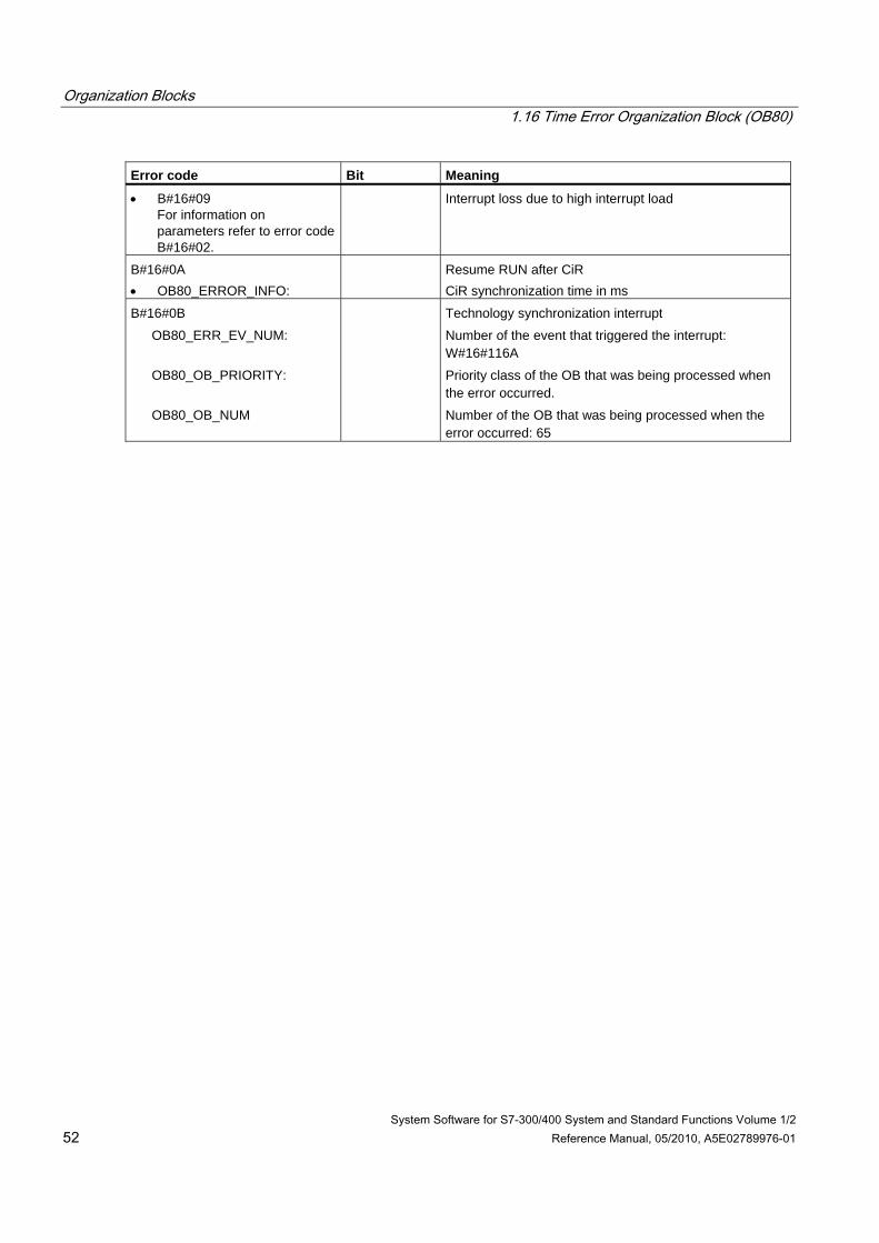
Organization Blocks 1.16 Time Error Organization Block (OB80)
System Software for S7-300/400 System and Standard Functions Volume 1/2 52 Reference Manual, 05/2010, A5E02789976-01
Error code Bit Meaning
• B#16#09 For information on parameters refer to error code B#16#02.
Interrupt loss due to high interrupt load
B#16#0A • OB80_ERROR_INFO:
Resume RUN after CiR CiR synchronization time in ms
B#16#0B
OB80_ERR_EV_NUM:
OB80_OB_PRIORITY:
OB80_OB_NUM
Technology synchronization interrupt
Number of the event that triggered the interrupt: W#16#116A
Priority class of the OB that was being processed when the error occurred.
Number of the OB that was being processed when the error occurred: 65
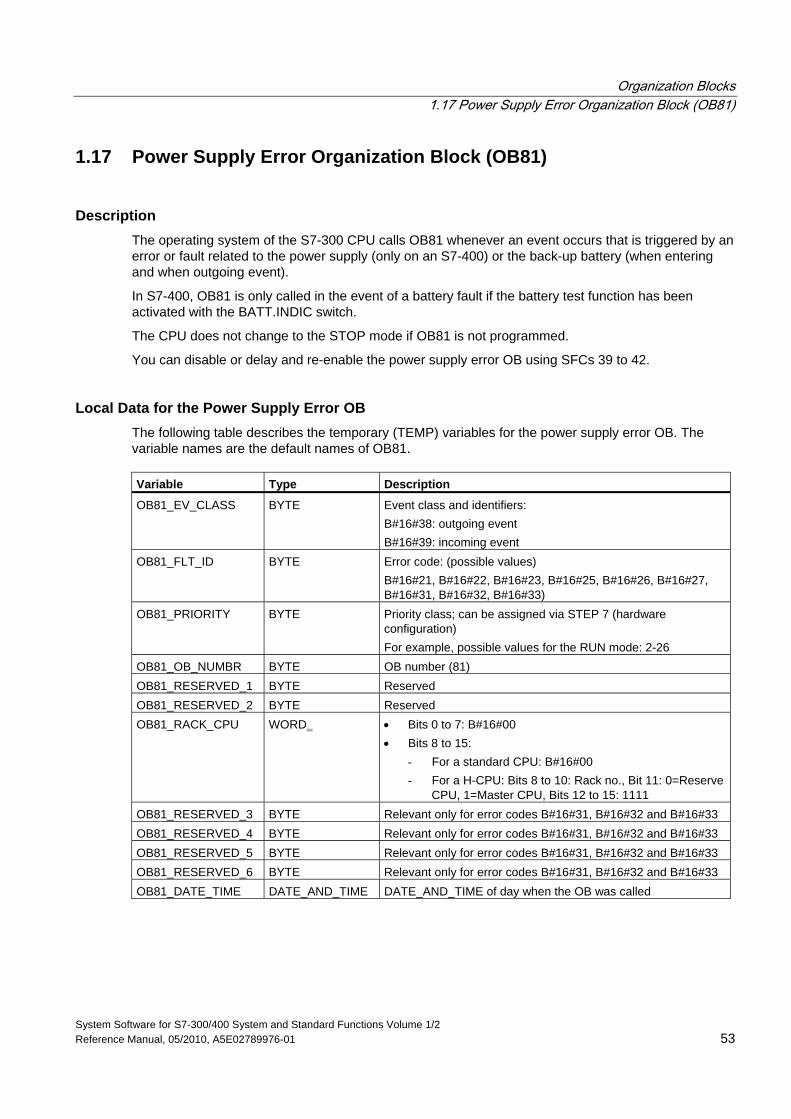
Organization Blocks 1.17 Power Supply Error Organization Block (OB81)
System Software for S7-300/400 System and Standard Functions Volume 1/2 Reference Manual, 05/2010, A5E02789976-01 53
1.17 Power Supply Error Organization Block (OB81)
Description The operating system of the S7-300 CPU calls OB81 whenever an event occurs that is triggered by an error or fault related to the power supply (only on an S7-400) or the back-up battery (when entering and when outgoing event).
In S7-400, OB81 is only called in the event of a battery fault if the battery test function has been activated with the BATT.INDIC switch.
The CPU does not change to the STOP mode if OB81 is not programmed.
You can disable or delay and re-enable the power supply error OB using SFCs 39 to 42.
Local Data for the Power Supply Error OB The following table describes the temporary (TEMP) variables for the power supply error OB. The variable names are the default names of OB81. Variable Type Description
OB81_EV_CLASS BYTE Event class and identifiers: B#16#38: outgoing event B#16#39: incoming event
OB81_FLT_ID BYTE Error code: (possible values) B#16#21, B#16#22, B#16#23, B#16#25, B#16#26, B#16#27, B#16#31, B#16#32, B#16#33)
OB81_PRIORITY BYTE Priority class; can be assigned via STEP 7 (hardware configuration) For example, possible values for the RUN mode: 2-26
OB81_OB_NUMBR BYTE OB number (81) OB81_RESERVED_1 BYTE Reserved OB81_RESERVED_2 BYTE Reserved OB81_RACK_CPU WORD • Bits 0 to 7: B#16#00
• Bits 8 to 15: - For a standard CPU: B#16#00 - For a H-CPU: Bits 8 to 10: Rack no., Bit 11: 0=Reserve
CPU, 1=Master CPU, Bits 12 to 15: 1111 OB81_RESERVED_3 BYTE Relevant only for error codes B#16#31, B#16#32 and B#16#33 OB81_RESERVED_4 BYTE Relevant only for error codes B#16#31, B#16#32 and B#16#33 OB81_RESERVED_5 BYTE Relevant only for error codes B#16#31, B#16#32 and B#16#33 OB81_RESERVED_6 BYTE Relevant only for error codes B#16#31, B#16#32 and B#16#33 OB81_DATE_TIME DATE_AND_TIME DATE_AND_TIME of day when the OB was called
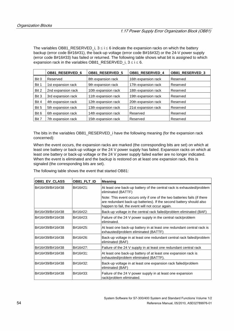
Organization Blocks 1.17 Power Supply Error Organization Block (OB81)
System Software for S7-300/400 System and Standard Functions Volume 1/2 54 Reference Manual, 05/2010, A5E02789976-01
The variables OB81_RESERVED_i, 3 ≤ i ≤ 6 indicate the expansion racks on which the battery backup (error code B#16#31), the back-up voltage (error code B#16#32) or the 24-V power supply (error code B#16#33) has failed or returned. The following table shows what bit is assigned to which expansion rack in the variables OB81_RESERVED_i, 3 ≤ i ≤ 6. OB81_RESERVED_6 OB81_RESERVED_5 OB81_RESERVED_4 OB81_RESERVED_3
Bit 0 Reserved 8th expansion rack 16th expansion rack Reserved Bit 1 1st expansion rack 9th expansion rack 17th expansion rack Reserved Bit 2 2nd expansion rack 10th expansion rack 18th expansion rack Reserved Bit 3 3rd expansion rack 11th expansion rack 19th expansion rack Reserved Bit 4 4th expansion rack 12th expansion rack 20th expansion rack Reserved Bit 5 5th expansion rack 13th expansion rack 21st expansion rack Reserved Bit 6 6th expansion rack 14th expansion rack Reserved Reserved Bit 7 7th expansion rack 15th expansion rack Reserved Reserved
The bits in the variables OB81_RESERVED_i have the following meaning (for the expansion rack concerned):
When the event occurs, the expansion racks are marked (the corresponding bits are set) on which at least one battery or back-up voltage or the 24 V power supply has failed. Expansion racks on which at least one battery or back-up voltage or the 24 V power supply failed earlier are no longer indicated. When the event is eliminated and the backup is restored on at least one expansion rack, this is signaled (the corresponding bits are set).
The following table shows the event that started OB81: OB81_EV_CLASS OB81_FLT_ID Meaning
B#16#39/B#16#38 B#16#21: At least one back-up battery of the central rack is exhausted/problem eliminated (BATTF) Note: This event occurs only if one of the two batteries fails (if there are redundant back-up batteries). If the second battery should also happen to fail, the event will not occur again.
B#16#39/B#16#38 B#16#22: Back-up voltage in the central rack failed/problem eliminated (BAF) B#16#39/B#16#38 B#16#23: Failure of the 24 V power supply in the central rack/problem
eliminated. B#16#39/B#16#38 B#16#25: At least one back-up battery in at least one redundant central rack is
exhausted/problem eliminated (BATTF) B#16#39/B#16#38 B#16#26: Back-up voltage in at least one redundant central rack failed/problem
eliminated (BAF) B#16#39/B#16#38 B#16#27: Failure of the 24 V supply in at least one redundant central rack B#16#39/B#16#38 B#16#31: At least one back-up battery of at least one expansion rack is
exhausted/problem eliminated (BATTF). B#16#39/B#16#38 B#16#32: Back-up voltage in at least one expansion rack failed/problem
eliminated (BAF) B#16#39/B#16#38 B#16#33: Failure of the 24 V power supply in at least one expansion
rack/problem eliminated.
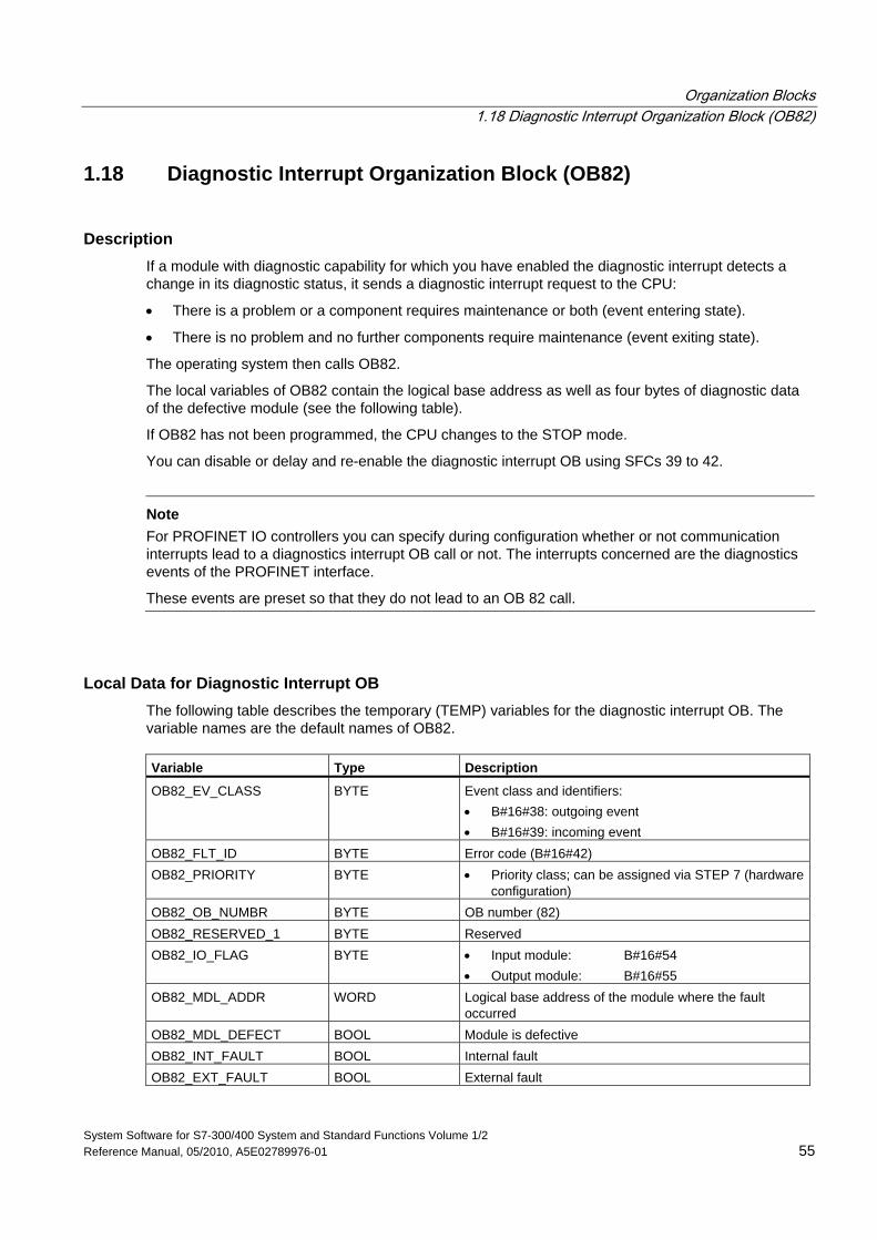
Organization Blocks 1.18 Diagnostic Interrupt Organization Block (OB82)
System Software for S7-300/400 System and Standard Functions Volume 1/2 Reference Manual, 05/2010, A5E02789976-01 55
1.18 Diagnostic Interrupt Organization Block (OB82)
Description If a module with diagnostic capability for which you have enabled the diagnostic interrupt detects a change in its diagnostic status, it sends a diagnostic interrupt request to the CPU:
• There is a problem or a component requires maintenance or both (event entering state).
• There is no problem and no further components require maintenance (event exiting state).
The operating system then calls OB82.
The local variables of OB82 contain the logical base address as well as four bytes of diagnostic data of the defective module (see the following table).
If OB82 has not been programmed, the CPU changes to the STOP mode.
You can disable or delay and re-enable the diagnostic interrupt OB using SFCs 39 to 42.
Note
For PROFINET IO controllers you can specify during configuration whether or not communication interrupts lead to a diagnostics interrupt OB call or not. The interrupts concerned are the diagnostics events of the PROFINET interface.
These events are preset so that they do not lead to an OB 82 call.
Local Data for Diagnostic Interrupt OB The following table describes the temporary (TEMP) variables for the diagnostic interrupt OB. The variable names are the default names of OB82. Variable Type Description
OB82_EV_CLASS BYTE Event class and identifiers: • B#16#38: outgoing event • B#16#39: incoming event
OB82_FLT_ID BYTE Error code (B#16#42) OB82_PRIORITY BYTE • Priority class; can be assigned via STEP 7 (hardware
configuration) OB82_OB_NUMBR BYTE OB number (82) OB82_RESERVED_1 BYTE Reserved OB82_IO_FLAG BYTE • Input module: B#16#54
• Output module: B#16#55 OB82_MDL_ADDR WORD Logical base address of the module where the fault
occurred OB82_MDL_DEFECT BOOL Module is defective OB82_INT_FAULT BOOL Internal fault OB82_EXT_FAULT BOOL External fault
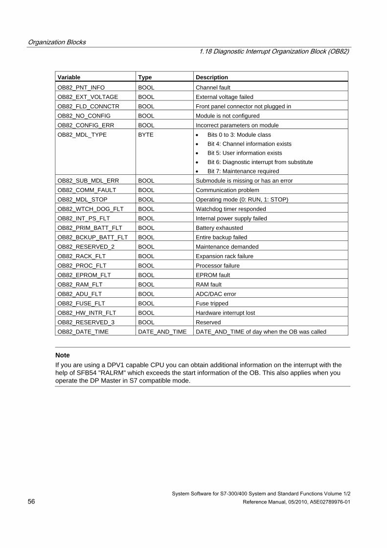
Organization Blocks 1.18 Diagnostic Interrupt Organization Block (OB82)
System Software for S7-300/400 System and Standard Functions Volume 1/2 56 Reference Manual, 05/2010, A5E02789976-01
Variable Type Description
OB82_PNT_INFO BOOL Channel fault OB82_EXT_VOLTAGE BOOL External voltage failed OB82_FLD_CONNCTR BOOL Front panel connector not plugged in OB82_NO_CONFIG BOOL Module is not configured OB82_CONFIG_ERR BOOL Incorrect parameters on module OB82_MDL_TYPE BYTE • Bits 0 to 3: Module class
• Bit 4: Channel information exists • Bit 5: User information exists • Bit 6: Diagnostic interrupt from substitute • Bit 7: Maintenance required
OB82_SUB_MDL_ERR BOOL Submodule is missing or has an error OB82_COMM_FAULT BOOL Communication problem OB82_MDL_STOP BOOL Operating mode (0: RUN, 1: STOP) OB82_WTCH_DOG_FLT BOOL Watchdog timer responded OB82_INT_PS_FLT BOOL Internal power supply failed OB82_PRIM_BATT_FLT BOOL Battery exhausted OB82_BCKUP_BATT_FLT BOOL Entire backup failed OB82_RESERVED_2 BOOL Maintenance demanded OB82_RACK_FLT BOOL Expansion rack failure OB82_PROC_FLT BOOL Processor failure OB82_EPROM_FLT BOOL EPROM fault OB82_RAM_FLT BOOL RAM fault OB82_ADU_FLT BOOL ADC/DAC error OB82_FUSE_FLT BOOL Fuse tripped OB82_HW_INTR_FLT BOOL Hardware interrupt lost OB82_RESERVED_3 BOOL Reserved OB82_DATE_TIME DATE_AND_TIME DATE_AND_TIME of day when the OB was called
Note
If you are using a DPV1 capable CPU you can obtain additional information on the interrupt with the help of SFB54 "RALRM" which exceeds the start information of the OB. This also applies when you operate the DP Master in S7 compatible mode.
Organization Blocks 1.19 Insert / Remove Module Interrupt Organization Block (OB83)
System Software for S7-300/400 System and Standard Functions Volume 1/2 Reference Manual, 05/2010, A5E02789976-01 57
1.19 Insert / Remove Module Interrupt Organization Block (OB83)
Description The CPU operating system calls OB83 in following situations:
• after insertion / removal of a configured module
• after modifications of module parameters under STEP 7 and download of changes to the CPU during RUN
If you have not programmed OB83, the CPU changes to STOP mode
You can disable/delay/enable the insert/remove interrupt OB with the help of SFCs 39 to 42.
Module insertion and removal Each time a configured module is removed or inserted during the RUN, STOP, and STARTUP modes, an insert/remove interrupt is generated (power supply modules, CPUs, adapter modules and IMs must not be removed in these modes). This interrupt causes an entry in the diagnostic buffer and in the system status list for the CPU involved. The insert/remove OB is also started if the CPU is in the RUN mode. If this OB has not been programmed, the CPU changes to the STOP mode.
Then system polls S7-400 modules in seconds intervals to detect insertion or removal. To enable the CPU to detect the removal and insertion of an S7-400 module, a minimum time interval of two seconds must expire between removal and insertion. This minimum time is slightly higher for other modules.
If you remove a configured module in the RUN mode, OB83 is started. Since the existence of modules is only monitored at intervals of one second, an access error may be detected first if the module is accessed directly or when the process image is updated.
If you insert a module in a configured slot in the RUN mode, the operating system checks whether the type of the module inserted corresponds to the recorded configuration. OB83 is then started and parameters are assigned if the module types match.
Special considerations for S7-300 • Central IO devices cannot be inserted and removed with S7-300.
• With respect to distributed IO devices, CPU 318 behaves like an S7-400-CPU. With all other S7-300 CPUs, there is an insert/remove interrupt only for 31x PN/DP CPUs, but then only for PROFINET IO components.
• With IM151/CPU (CPU with ET 200S), there is an insert/remove interrupt only for central IO devices.
Organization Blocks 1.19 Insert / Remove Module Interrupt Organization Block (OB83)
System Software for S7-300/400 System and Standard Functions Volume 1/2 58 Reference Manual, 05/2010, A5E02789976-01
Reconfiguring modules You can reassign the parameters to existing modules when you modify your system configuration during runtime (CiR). This reassignment of parameters is performed by transferring the required parameter data records to the modules.
This is the procedure:
1. OB83 will be started (Start event W#16#3367) after you have assigned new parameters to a module under STEP 7 and downloaded this configuration to the CPU in RUN mode. Relevant OB -start information is the logical basic address (OB83_MDL_ADDR) and the module type (OB83_MDL_TYPE). Module I/O data may be incorrect as of now, which means that no SFC may be busy sending data records to this module.
2. The module parameters are reassigned after OB83 was executed.
3. OB83 will be restarted after the parameters have been assigned (Start event W#16#3267, provided this parameter assignment was successful, or W#16#3968 if failed). The module's I/O data response is identical to their response after an insertion interrupt, that is, currently they may be incorrect. You can now call SFCs again to send data records to the module.
Local Data for OB83 The following table describes the temporary (TEMP) variables for the insert/remove module interrupt OB. The variable names are the default names of OB83. Variable Type Description
OB83_EV_CLASS BYTE Event class and identifiers: • B#16#32: End of reassignment of module parameters • B#16#33: Start of reassignment of module parameters • B#16#38: module inserted • B#16#39: module removed or not responding, or end of
parameter assignment OB83_FLT_ID BYTE Error code: (possible values B#16#51, B#16#54, B#16#55,
B#16#56, B#16#58, B#16#61, B#16#63, B#16#64, B#16#65, B#16#66, B#16#67, B#16#68)
OB83_PRIORITY BYTE • Priority class; can be assigned via STEP 7 (hardware configuration)
OB83_OB_NUMBR BYTE OB number (83) OB83_RESERVED_1 BYTE Identification of module or submodule/interface module OB83_MDL_TD BYTE Range:
• B#16#54: Peripheral input (PI) • B#16#55: Peripheral output (PQ)
Organization Blocks 1.19 Insert / Remove Module Interrupt Organization Block (OB83)
System Software for S7-300/400 System and Standard Functions Volume 1/2 Reference Manual, 05/2010, A5E02789976-01 59
Variable Type Description
OB83_MDL_ADDR WORD • Central or distributed PROFIBUS DP: Logical base address of the module affected. If it is a mixed module, it is the smallest logical address used in the module. If the I and O addresses in the mixed block are equal, the logical base address is the one that receives the event identifier.
• Distributed PROFINET IO: Logical base address of the module/submodule
OB83_RACK_NUM WORD • If OB83_RESERVED_1 =B#16#A0: number of submodule/interface submodule (low byte)
• If OB83_RESERVED_1 = B#16#C4: - central: rack number - distributed PROFIBUS DP: number of DP station (low
byte) and DP master system ID (high byte) - distributed PROFINET IO: physical address: identifier
bit (bit 15, 1 = PROFINET IO), IO system ID (bits 11 to 14) and device number (bits 0 to 10)
OB83_MDL_TYPE WORD • Central or distributed PROFIBUS DP: Module type of affected module (X: irrelevant to the user): - W#16#X5XX: analog module - W#16#X8XX: function module - W#16#XCXX: CP - W#16#XFXX: digital module
• Distributed PROFINET IO - W#16#8101: module type of the inserted module is the
same as the module type of the removed module - W#16#8102: module type of the inserted module is not
the same as the module type of the removed module OB83_DATE_TIME DATE_AND_TIME DATE_AND_TIME of day when the OB was called
Organization Blocks 1.19 Insert / Remove Module Interrupt Organization Block (OB83)
System Software for S7-300/400 System and Standard Functions Volume 1/2 60 Reference Manual, 05/2010, A5E02789976-01
The following table shows the event that started OB83:
OB83_EV_CLASS OB83_FLT_ID Meaning
B#16#39 B#16#51 PROFINET IO module removed B#16#39 B#16#54 PROFINET IO submodule removed B#16#38 B#16#54 PROFINET IO submodule inserted and matches configured
submodule B#16#38 B#16#55 PROFINET IO submodule inserted, but does not match configured
submodule B#16#38 B#16#56 PROFINET IO submodule inserted, but error with module parametersB#16#38 B#16#58 PROFINET IO submodule, access error corrected B#16#39 B#16#61 Module removed or not responding
OB83_MDL_TYPE: Actual module type B#16#38 B#16#61 Module inserted. Module type OK
OB83_MDL_TYPE: Actual module type B#16#38 B#16#63 Module inserted but incorrect module type
OB83_MDL_TYPE: Actual module type B#16#38 B#16#64 Module inserted but problem (module ID cannot be read)
OB83_MDL_TYPE: Configured module type B#16#38 B#16#65 Module inserted but error in module parameter assignment
OB83_MDL_TYPE: Actual module type B#16#39 B#16#66 Module not responding, load voltage error B#16#38 B#16#66 Module responds again, load voltage error corrected B#16#33 B#16#67 Start of module reconfiguration B#16#32 B#16#67 End of module reconfiguration B#16#39 B#16#68 Module reconfiguration terminated with error
Note
If you are using a DPV1- or PROFINET-capable CPU you can obtain additional information on the interrupt with the help of SFB54 "RALRM" which exceeds the start information of the OB. This also applies when you operate the DP master in S7 compatible mode.
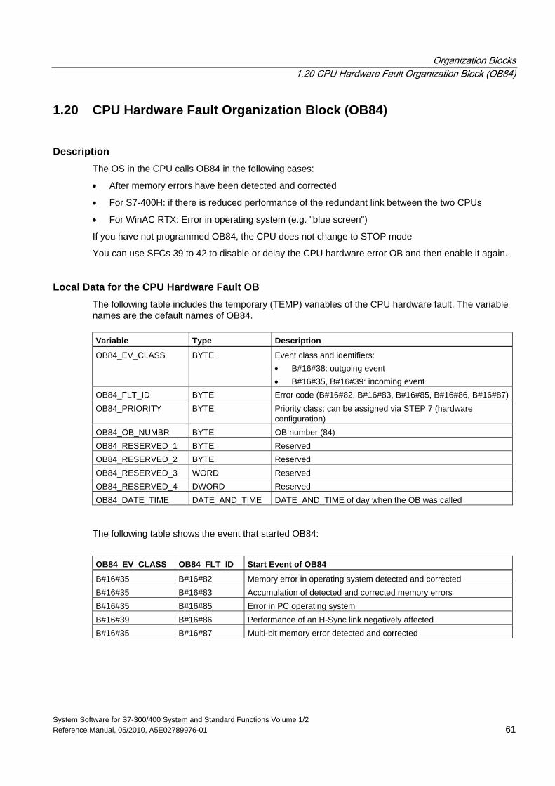
Organization Blocks 1.20 CPU Hardware Fault Organization Block (OB84)
System Software for S7-300/400 System and Standard Functions Volume 1/2 Reference Manual, 05/2010, A5E02789976-01 61
1.20 CPU Hardware Fault Organization Block (OB84)
Description The OS in the CPU calls OB84 in the following cases:
• After memory errors have been detected and corrected
• For S7-400H: if there is reduced performance of the redundant link between the two CPUs
• For WinAC RTX: Error in operating system (e.g. "blue screen")
If you have not programmed OB84, the CPU does not change to STOP mode
You can use SFCs 39 to 42 to disable or delay the CPU hardware error OB and then enable it again.
Local Data for the CPU Hardware Fault OB The following table includes the temporary (TEMP) variables of the CPU hardware fault. The variable names are the default names of OB84. Variable Type Description
OB84_EV_CLASS BYTE Event class and identifiers: • B#16#38: outgoing event • B#16#35, B#16#39: incoming event
OB84_FLT_ID BYTE Error code (B#16#82, B#16#83, B#16#85, B#16#86, B#16#87)OB84_PRIORITY BYTE Priority class; can be assigned via STEP 7 (hardware
configuration) OB84_OB_NUMBR BYTE OB number (84) OB84_RESERVED_1 BYTE Reserved OB84_RESERVED_2 BYTE Reserved OB84_RESERVED_3 WORD Reserved OB84_RESERVED_4 DWORD Reserved OB84_DATE_TIME DATE_AND_TIME DATE_AND_TIME of day when the OB was called
The following table shows the event that started OB84:
OB84_EV_CLASS OB84_FLT_ID Start Event of OB84
B#16#35 B#16#82 Memory error in operating system detected and corrected B#16#35 B#16#83 Accumulation of detected and corrected memory errors B#16#35 B#16#85 Error in PC operating system B#16#39 B#16#86 Performance of an H-Sync link negatively affected B#16#35 B#16#87 Multi-bit memory error detected and corrected
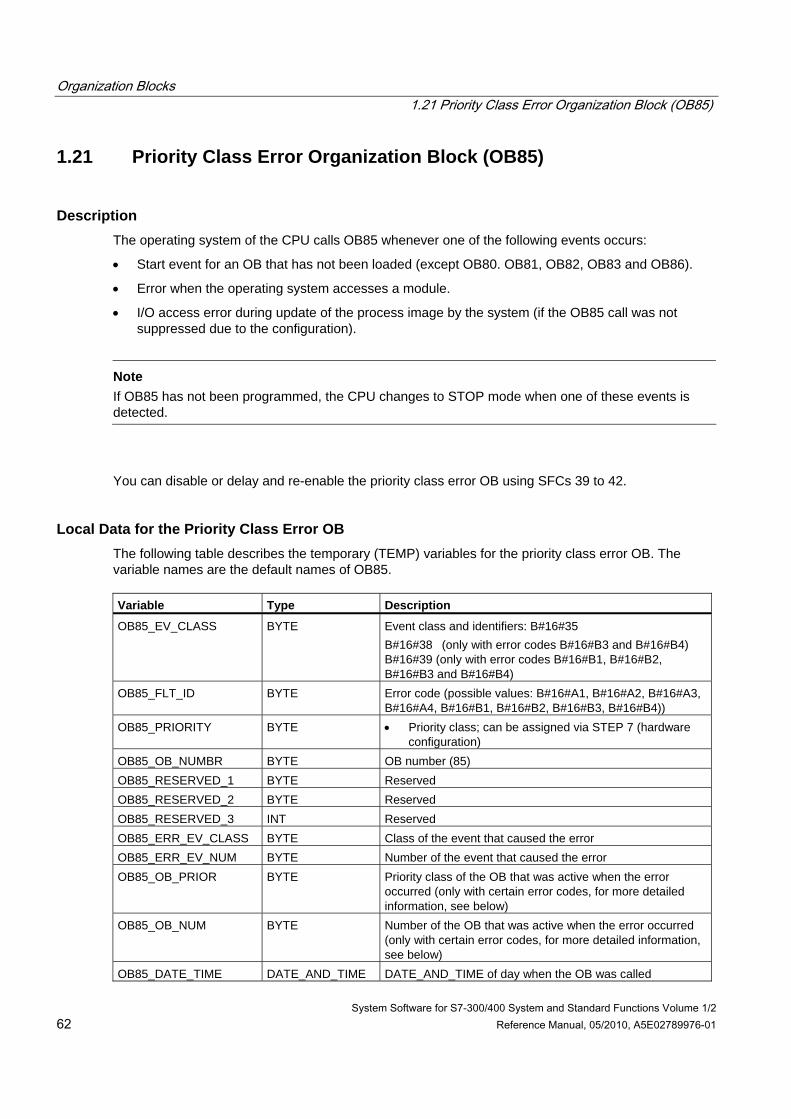
Organization Blocks 1.21 Priority Class Error Organization Block (OB85)
System Software for S7-300/400 System and Standard Functions Volume 1/2 62 Reference Manual, 05/2010, A5E02789976-01
1.21 Priority Class Error Organization Block (OB85)
Description The operating system of the CPU calls OB85 whenever one of the following events occurs:
• Start event for an OB that has not been loaded (except OB80. OB81, OB82, OB83 and OB86).
• Error when the operating system accesses a module.
• I/O access error during update of the process image by the system (if the OB85 call was not suppressed due to the configuration).
Note
If OB85 has not been programmed, the CPU changes to STOP mode when one of these events is detected.
You can disable or delay and re-enable the priority class error OB using SFCs 39 to 42.
Local Data for the Priority Class Error OB The following table describes the temporary (TEMP) variables for the priority class error OB. The variable names are the default names of OB85. Variable Type Description
OB85_EV_CLASS BYTE Event class and identifiers: B#16#35 B#16#38 (only with error codes B#16#B3 and B#16#B4) B#16#39 (only with error codes B#16#B1, B#16#B2, B#16#B3 and B#16#B4)
OB85_FLT_ID BYTE Error code (possible values: B#16#A1, B#16#A2, B#16#A3, B#16#A4, B#16#B1, B#16#B2, B#16#B3, B#16#B4))
OB85_PRIORITY BYTE • Priority class; can be assigned via STEP 7 (hardware configuration)
OB85_OB_NUMBR BYTE OB number (85) OB85_RESERVED_1 BYTE Reserved OB85_RESERVED_2 BYTE Reserved OB85_RESERVED_3 INT Reserved OB85_ERR_EV_CLASS BYTE Class of the event that caused the error OB85_ERR_EV_NUM BYTE Number of the event that caused the error OB85_OB_PRIOR BYTE Priority class of the OB that was active when the error
occurred (only with certain error codes, for more detailed information, see below)
OB85_OB_NUM BYTE Number of the OB that was active when the error occurred (only with certain error codes, for more detailed information, see below)
OB85_DATE_TIME DATE_AND_TIME DATE_AND_TIME of day when the OB was called
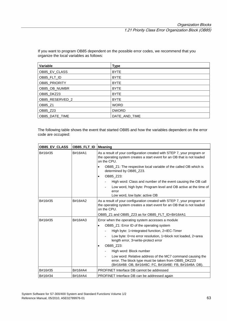
Organization Blocks 1.21 Priority Class Error Organization Block (OB85)
System Software for S7-300/400 System and Standard Functions Volume 1/2 Reference Manual, 05/2010, A5E02789976-01 63
If you want to program OB85 dependent on the possible error codes, we recommend that you organize the local variables as follows: Variable Type
OB85_EV_CLASS BYTE OB85_FLT_ID BYTE OB85_PRIORITY BYTE OB85_OB_NUMBR BYTE OB85_DKZ23 BYTE OB85_RESERVED_2 BYTE OB85_Z1 WORD OB85_Z23 DWORD OB85_DATE_TIME DATE_AND_TIME
The following table shows the event that started OB85 and how the variables dependent on the error code are occupied:
OB85_EV_CLASS OB85_FLT_ID Meaning
B#16#35 B#16#A1 As a result of your configuration created with STEP 7, your program or the operating system creates a start event for an OB that is not loaded on the CPU. • OB85_Z1: The respective local variable of the called OB which is
determined by OB85_Z23. • OB85_Z23:
- High word: Class and number of the event causing the OB call - Low word, high byte: Program level and OB active at the time of
error Low word, low byte: active OB
B#16#35 B#16#A2 As a result of your configuration created with STEP 7, your program or the operating system creates a start event for an OB that is not loaded on the CPU. OB85_Z1 and OB85_Z23 as for OB85_FLT_ID=B#16#A1
B#16#35 B#16#A3 Error when the operating system accesses a module • OB85_Z1: Error ID of the operating system
- High byte: 1=integrated function, 2=IEC-Timer - Low byte: 0=no error resolution, 1=block not loaded, 2=area
length error, 3=write-protect error • OB85_Z23:
- High word: Block number - Low word: Relative address of the MC7 command causing the
error. The block type must be taken from OB85_DKZ23 (B#16#88: OB, B#16#8C: FC, B#16#8E: FB, B#16#8A: DB).
B#16#35 B#16#A4 PROFINET Interface DB cannot be addressed B#16#34 B#16#A4 PROFINET Interface DB can be addressed again
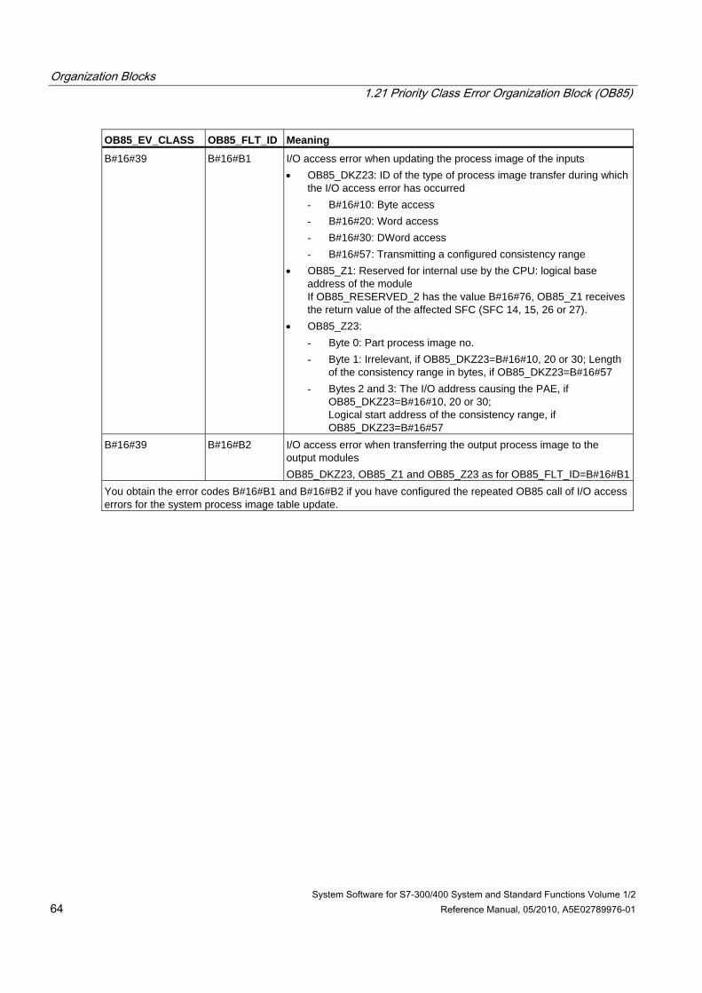
Organization Blocks 1.21 Priority Class Error Organization Block (OB85)
System Software for S7-300/400 System and Standard Functions Volume 1/2 64 Reference Manual, 05/2010, A5E02789976-01
OB85_EV_CLASS OB85_FLT_ID Meaning
B#16#39 B#16#B1 I/O access error when updating the process image of the inputs • OB85_DKZ23: ID of the type of process image transfer during which
the I/O access error has occurred - B#16#10: Byte access - B#16#20: Word access - B#16#30: DWord access - B#16#57: Transmitting a configured consistency range
• OB85_Z1: Reserved for internal use by the CPU: logical base address of the module If OB85_RESERVED_2 has the value B#16#76, OB85_Z1 receives the return value of the affected SFC (SFC 14, 15, 26 or 27).
• OB85_Z23: - Byte 0: Part process image no. - Byte 1: Irrelevant, if OB85_DKZ23=B#16#10, 20 or 30; Length
of the consistency range in bytes, if OB85_DKZ23=B#16#57 - Bytes 2 and 3: The I/O address causing the PAE, if
OB85_DKZ23=B#16#10, 20 or 30; Logical start address of the consistency range, if OB85_DKZ23=B#16#57
B#16#39 B#16#B2 I/O access error when transferring the output process image to the output modules OB85_DKZ23, OB85_Z1 and OB85_Z23 as for OB85_FLT_ID=B#16#B1
You obtain the error codes B#16#B1 and B#16#B2 if you have configured the repeated OB85 call of I/O access errors for the system process image table update.
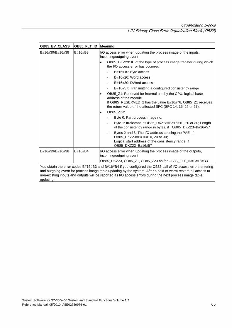
Organization Blocks 1.21 Priority Class Error Organization Block (OB85)
System Software for S7-300/400 System and Standard Functions Volume 1/2 Reference Manual, 05/2010, A5E02789976-01 65
OB85_EV_CLASS OB85_FLT_ID Meaning
B#16#39/B#16#38 B#16#B3 I/O access error when updating the process image of the inputs, incoming/outgoing event • OB85_DKZ23: ID of the type of process image transfer during which
the I/O access error has occurred - B#16#10: Byte access - B#16#20: Word access - B#16#30: DWord access - B#16#57: Transmitting a configured consistency range
• OB85_Z1: Reserved for internal use by the CPU: logical base address of the module If OB85_RESERVED_2 has the value B#16#76, OB85_Z1 receives the return value of the affected SFC (SFC 14, 15, 26 or 27).
• OB85_Z23: - Byte 0: Part process image no. - Byte 1: Irrelevant, if OB85_DKZ23=B#16#10, 20 or 30; Length
of the consistency range in bytes, if OB85_DKZ23=B#16#57 - Bytes 2 and 3: The I/O address causing the PAE, if
OB85_DKZ23=B#16#10, 20 or 30; Logical start address of the consistency range, if OB85_DKZ23=B#16#57
B#16#39/B#16#38 B#16#B4 I/O access error when updating the process image of the outputs, incoming/outgoing event OB85_DKZ23, OB85_Z1, OB85_Z23 as for OB85_FLT_ID=B#16#B3
You obtain the error codes B#16#B3 and B#16#B4 if you configured the OB85 call of I/O access errors entering and outgoing event for process image table updating by the system. After a cold or warm restart, all access to non-existing inputs and outputs will be reported as I/O access errors during the next process image table updating.
Organization Blocks 1.22 Rack Failure Organization Block (OB86)
System Software for S7-300/400 System and Standard Functions Volume 1/2 66 Reference Manual, 05/2010, A5E02789976-01
1.22 Rack Failure Organization Block (OB86)
Description The operating system of the CPU calls OB86 in the following situations:
• Failure of a central expansion unit (not with S7-300) is detected (both event entering and exiting state).
• The failure of a DP master system is detected (both event entering and exiting state).
• The failure of a station when using distributed I/O (PROFIBUS DP or PROFINET IO) is detected (both event entering and exiting state).
• You have disabled a station when using distributed I/O (PROFIBUS DP or PROFINET IO) with SFC 12 "D_ACT_DP" and the setting MODE=4.
• You have enabled a station when using distributed I/O (PROFIBUS DP or PROFINET IO) with SFC 12 "D_ACT_DP" and the setting MODE=3.
If OB86 has not been programmed, the CPU changes to the STOP mode when this type of error is detected.
You can disable or delay and re-enable OB86 using SFCs 39 to 42.
Local Data for the Rack Failure OB The following table describes the temporary (TEMP) variables for the rack failure OB. The variable names are the default names of OB86. Variable Type Description
OB86_EV_CLASS BYTE Event class and identifiers: • B#16#32: Enabling a station with SFC 12 "D_ACT_DP"
with MODE=3 • B#16#33: Disabling a station with SFC 12 "D_ACT_DP"
with MODE=3 • B#16#38: Event exiting state • B#16#39: Event entering state
OB86_FLT_ID BYTE Error code: (possible values: B#16#C1, B#16#C2, B#16#C3, B#16#C4, B#16#C5, B#16#C6, B#16#C7, B#16#C8, B#16#C9, B#16#CA, B#16#CB, B#16#CC, B#16#CD, B#16#CE, B#16#CF)
OB86_PRIORITY BYTE Priority class; can be assigned via STEP 7 (hardware configuration)
OB86_OB_NUMBR BYTE OB number (86) OB86_RESERVED_1 BYTE Reserved OB86_RESERVED_2 BYTE Reserved OB86_MDL_ADDR WORD Depends on the error code OB86_RACKS_FLTD Array [0 ..31]
of BOOL Depends on the error code
OB86_DATE_TIME DATE_AND_TIME DATE_AND_TIME of day when the OB was called
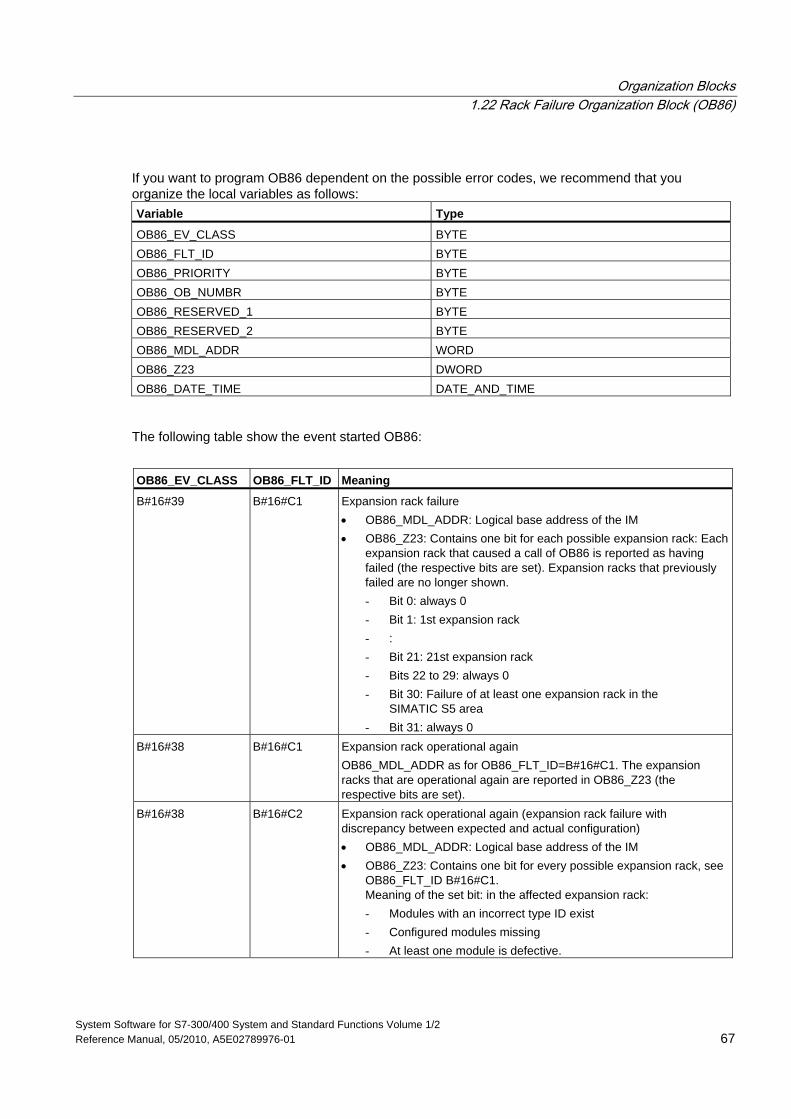
Organization Blocks 1.22 Rack Failure Organization Block (OB86)
System Software for S7-300/400 System and Standard Functions Volume 1/2 Reference Manual, 05/2010, A5E02789976-01 67
If you want to program OB86 dependent on the possible error codes, we recommend that you organize the local variables as follows: Variable Type
OB86_EV_CLASS BYTE OB86_FLT_ID BYTE OB86_PRIORITY BYTE OB86_OB_NUMBR BYTE OB86_RESERVED_1 BYTE OB86_RESERVED_2 BYTE OB86_MDL_ADDR WORD OB86_Z23 DWORD OB86_DATE_TIME DATE_AND_TIME
The following table show the event started OB86:
OB86_EV_CLASS OB86_FLT_ID Meaning
B#16#39 B#16#C1 Expansion rack failure • OB86_MDL_ADDR: Logical base address of the IM • OB86_Z23: Contains one bit for each possible expansion rack: Each
expansion rack that caused a call of OB86 is reported as having failed (the respective bits are set). Expansion racks that previously failed are no longer shown. - Bit 0: always 0 - Bit 1: 1st expansion rack - : - Bit 21: 21st expansion rack - Bits 22 to 29: always 0 - Bit 30: Failure of at least one expansion rack in the
SIMATIC S5 area - Bit 31: always 0
B#16#38 B#16#C1 Expansion rack operational again OB86_MDL_ADDR as for OB86_FLT_ID=B#16#C1. The expansion racks that are operational again are reported in OB86_Z23 (the respective bits are set).
B#16#38 B#16#C2 Expansion rack operational again (expansion rack failure with discrepancy between expected and actual configuration) • OB86_MDL_ADDR: Logical base address of the IM • OB86_Z23: Contains one bit for every possible expansion rack, see
OB86_FLT_ID B#16#C1. Meaning of the set bit: in the affected expansion rack: - Modules with an incorrect type ID exist - Configured modules missing - At least one module is defective.
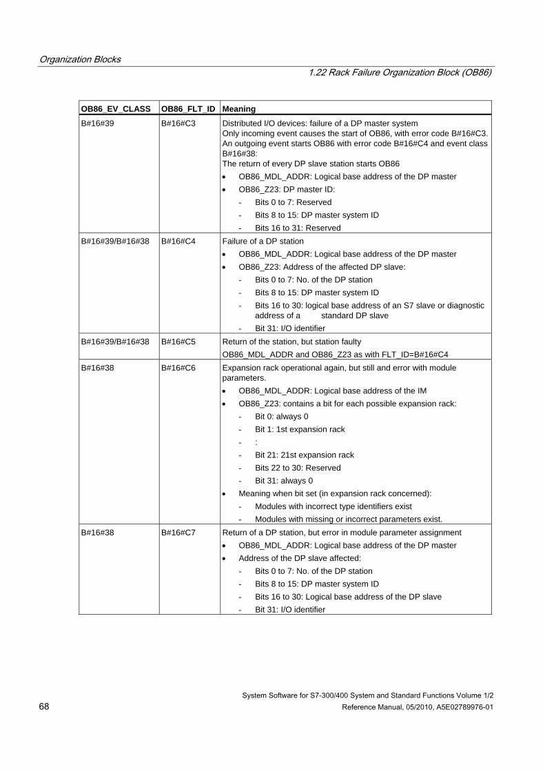
Organization Blocks 1.22 Rack Failure Organization Block (OB86)
System Software for S7-300/400 System and Standard Functions Volume 1/2 68 Reference Manual, 05/2010, A5E02789976-01
OB86_EV_CLASS OB86_FLT_ID Meaning
B#16#39 B#16#C3 Distributed I/O devices: failure of a DP master system Only incoming event causes the start of OB86, with error code B#16#C3. An outgoing event starts OB86 with error code B#16#C4 and event class B#16#38: The return of every DP slave station starts OB86 • OB86_MDL_ADDR: Logical base address of the DP master • OB86_Z23: DP master ID:
- Bits 0 to 7: Reserved - Bits 8 to 15: DP master system ID - Bits 16 to 31: Reserved
B#16#39/B#16#38 B#16#C4 Failure of a DP station • OB86_MDL_ADDR: Logical base address of the DP master • OB86_Z23: Address of the affected DP slave:
- Bits 0 to 7: No. of the DP station - Bits 8 to 15: DP master system ID - Bits 16 to 30: logical base address of an S7 slave or diagnostic
address of a standard DP slave - Bit 31: I/O identifier
B#16#39/B#16#38 B#16#C5 Return of the station, but station faulty OB86_MDL_ADDR and OB86_Z23 as with FLT_ID=B#16#C4
B#16#38 B#16#C6 Expansion rack operational again, but still and error with module parameters. • OB86_MDL_ADDR: Logical base address of the IM • OB86_Z23: contains a bit for each possible expansion rack:
- Bit 0: always 0 - Bit 1: 1st expansion rack - : - Bit 21: 21st expansion rack - Bits 22 to 30: Reserved - Bit 31: always 0
• Meaning when bit set (in expansion rack concerned): - Modules with incorrect type identifiers exist - Modules with missing or incorrect parameters exist.
B#16#38 B#16#C7 Return of a DP station, but error in module parameter assignment • OB86_MDL_ADDR: Logical base address of the DP master • Address of the DP slave affected:
- Bits 0 to 7: No. of the DP station - Bits 8 to 15: DP master system ID - Bits 16 to 30: Logical base address of the DP slave - Bit 31: I/O identifier
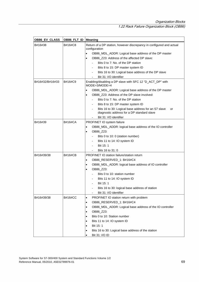
Organization Blocks 1.22 Rack Failure Organization Block (OB86)
System Software for S7-300/400 System and Standard Functions Volume 1/2 Reference Manual, 05/2010, A5E02789976-01 69
OB86_EV_CLASS OB86_FLT_ID Meaning
B#16#38 B#16#C8 Return of a DP station, however discrepancy in configured and actual configuration • OB86_MDL_ADDR: Logical base address of the DP master • OB86_Z23: Address of the affected DP slave:
- Bits 0 to 7: No. of the DP station - Bits 8 to 15: DP master system ID - Bits 16 to 30: Logical base address of the DP slave - Bit 31: I/O identifier
B#16#32/B#16#33 B#16#C9 Enabling/disabling a DP slave with SFC 12 "D_ACT_DP" with MODE=3/MODE=4 • OB86_MDL_ADDR: Logical base address of the DP master • OB86_Z23: Address of the DP slave involved:
- Bits 0 to 7: No. of the DP station - Bits 8 to 15: DP master system ID - Bits 16 to 30: Logical base address for an S7 slave or
diagnostic address for a DP standard slave - Bit 31: I/O identifier
B#16#39 B#16#CA PROFINET IO system failure • OB86_MDL_ADDR: logical base address of the IO controller • OB86_Z23:
- Bits 0 to 10: 0 (station number) - Bits 11 to 14: IO system ID - Bit 15: 1 - Bits 16 to 31: 0
B#16#39/38 B#16#CB PROFINET IO station failure/station return • OB86_RESERVED_1: B#16#C4 • OB86_MDL_ADDR: logical base address of IO controller • OB86_Z23:
- Bits 0 to 10: station number - Bits 11 to 14: IO system ID - Bit 15: 1 - Bits 16 to 30: logical base address of station - Bit 31: I/O identifier
B#16#39/38 B#16#CC • PROFINET IO station return with problem • OB86_RESERVED_1: B#16#C4 • OB86_MDL_ADDR: Logical base address of the IO controller • OB86_Z23: • Bits 0 to 10: Station number • Bits 11 to 14: IO system ID • Bit 15: 1 • Bits 16 to 30: Logical base address of the station • Bit 31: I/O ID
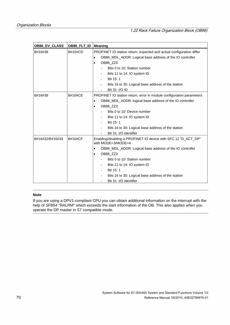
Organization Blocks 1.22 Rack Failure Organization Block (OB86)
System Software for S7-300/400 System and Standard Functions Volume 1/2 70 Reference Manual, 05/2010, A5E02789976-01
OB86_EV_CLASS OB86_FLT_ID Meaning
B#16#38 B#16#CD PROFINET IO station return, expected and actual configuration differ • OB86_MDL_ADDR: Logical base address of the IO controller • OB86_Z23:
- Bits 0 to 10: Station number - Bits 11 to 14: IO system ID - Bit 15: 1 - Bits 16 to 30: Logical base address of the station - Bit 31: I/O ID
B#16#38 B#16#CE PROFINET IO station return, error in module configuration parameters • OB86_MDL_ADDR: logical base address of the IO controller • OB86_Z23:
- Bits 0 to 10: Device number - Bits 11 to 14: IO system ID - Bit 15: 1 - Bits 16 to 30: Logical base address of the station - Bit 31: I/O identifier
B#16#32/B#16#33 B#16#CF Enabling/disabling a PROFINET IO device with SFC 12 "D_ACT_DP" with MODE=3/MODE=4 • OB86_MDL_ADDR: Logical base address of the IO controller • OB86_Z23:
- Bits 0 to 10: Station number - Bits 11 to 14: IO system ID - Bit 15: 1 - Bits 16 to 30: Logical base address of the station - Bit 31: I/O identifier
Note
If you are using a DPV1-compliant CPU you can obtain additional information on the interrupt with the help of SFB54 "RALRM" which exceeds the start information of the OB. This also applies when you operate the DP master in S7 compatible mode.
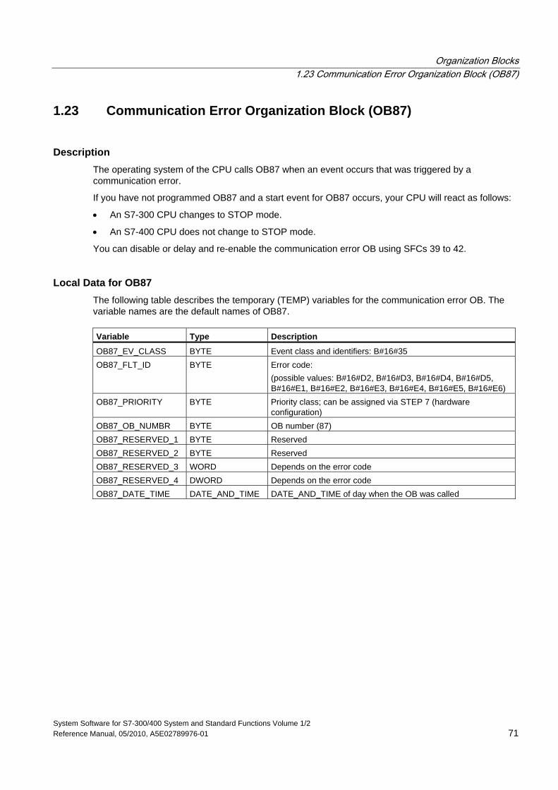
Organization Blocks 1.23 Communication Error Organization Block (OB87)
System Software for S7-300/400 System and Standard Functions Volume 1/2 Reference Manual, 05/2010, A5E02789976-01 71
1.23 Communication Error Organization Block (OB87)
Description The operating system of the CPU calls OB87 when an event occurs that was triggered by a communication error.
If you have not programmed OB87 and a start event for OB87 occurs, your CPU will react as follows:
• An S7-300 CPU changes to STOP mode.
• An S7-400 CPU does not change to STOP mode.
You can disable or delay and re-enable the communication error OB using SFCs 39 to 42.
Local Data for OB87 The following table describes the temporary (TEMP) variables for the communication error OB. The variable names are the default names of OB87. Variable Type Description
OB87_EV_CLASS BYTE Event class and identifiers: B#16#35 OB87_FLT_ID BYTE Error code:
(possible values: B#16#D2, B#16#D3, B#16#D4, B#16#D5, B#16#E1, B#16#E2, B#16#E3, B#16#E4, B#16#E5, B#16#E6)
OB87_PRIORITY BYTE Priority class; can be assigned via STEP 7 (hardware configuration)
OB87_OB_NUMBR BYTE OB number (87) OB87_RESERVED_1 BYTE Reserved OB87_RESERVED_2 BYTE Reserved OB87_RESERVED_3 WORD Depends on the error code OB87_RESERVED_4 DWORD Depends on the error code OB87_DATE_TIME DATE_AND_TIME DATE_AND_TIME of day when the OB was called
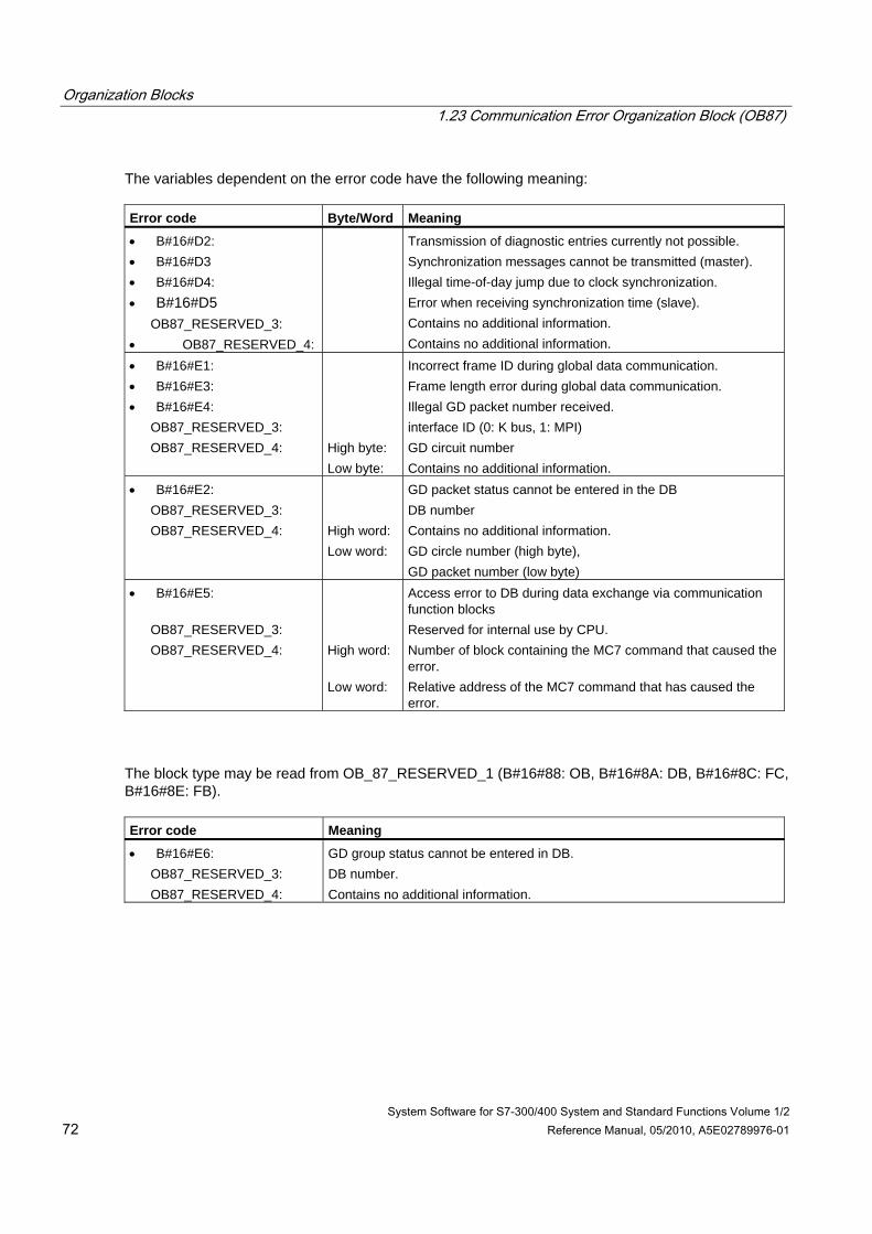
Organization Blocks 1.23 Communication Error Organization Block (OB87)
System Software for S7-300/400 System and Standard Functions Volume 1/2 72 Reference Manual, 05/2010, A5E02789976-01
The variables dependent on the error code have the following meaning: Error code Byte/Word Meaning
• B#16#D2: • B#16#D3 • B#16#D4: • B#16#D5 OB87_RESERVED_3: • OB87_RESERVED_4:
Transmission of diagnostic entries currently not possible. Synchronization messages cannot be transmitted (master). Illegal time-of-day jump due to clock synchronization. Error when receiving synchronization time (slave). Contains no additional information. Contains no additional information.
• B#16#E1: • B#16#E3: • B#16#E4: OB87_RESERVED_3: OB87_RESERVED_4:
High byte: Low byte:
Incorrect frame ID during global data communication. Frame length error during global data communication. Illegal GD packet number received. interface ID (0: K bus, 1: MPI) GD circuit number Contains no additional information.
• B#16#E2: OB87_RESERVED_3: OB87_RESERVED_4:
High word: Low word:
GD packet status cannot be entered in the DB DB number Contains no additional information. GD circle number (high byte), GD packet number (low byte)
• B#16#E5:
OB87_RESERVED_3: OB87_RESERVED_4:
High word: Low word:
Access error to DB during data exchange via communication function blocks Reserved for internal use by CPU. Number of block containing the MC7 command that caused the error. Relative address of the MC7 command that has caused the error.
The block type may be read from OB_87_RESERVED_1 (B#16#88: OB, B#16#8A: DB, B#16#8C: FC, B#16#8E: FB). Error code Meaning
• B#16#E6: OB87_RESERVED_3: OB87_RESERVED_4:
GD group status cannot be entered in DB. DB number. Contains no additional information.
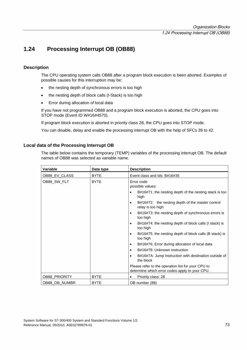
Organization Blocks 1.24 Processing Interrupt OB (OB88)
System Software for S7-300/400 System and Standard Functions Volume 1/2 Reference Manual, 05/2010, A5E02789976-01 73
1.24 Processing Interrupt OB (OB88)
Description The CPU operating system calls OB88 after a program block execution is been aborted. Examples of possible causes for this interruption may be:
• the nesting depth of synchronous errors is too high
• the nesting depth of block calls (I-Stack) is too high
• Error during allocation of local data
If you have not programmed OB88 and a program block execution is aborted, the CPU goes into STOP mode (Event ID W#16#4570).
If program block execution is aborted in priority class 28, the CPU goes into STOP mode.
You can disable, delay and enable the processing interrupt OB with the help of SFCs 39 to 42.
Local data of the Processing Interrupt OB The table below contains the temporary (TEMP) variables of the processing interrupt OB. The default names of OB88 was selected as variable name. Variable Data type Description
OB88_EV_CLASS BYTE Event class and Ids: B#16#35 OB88_SW_FLT BYTE Error code
possible values: • B#16#71: the nesting depth of the nesting stack is too
high • B#16#72: the nesting depth of the master control
relay is too high • B#16#73: the nesting depth of synchronous errors is
too high • B#16#74: the nesting depth of block calls (I stack) is
too high • B#16#75: the nesting depth of block calls (B stack) is
too high • B#16#76: Error during allocation of local data • B#16#78: Unknown instruction • B#16#7A: Jump instruction with destination outside of
the block Please refer to the operation list for your CPU to determine which error codes apply to your CPU.
OB88_PRIORITY BYTE • Priority class: 28 OB88_OB_NUMBR BYTE OB number (88)
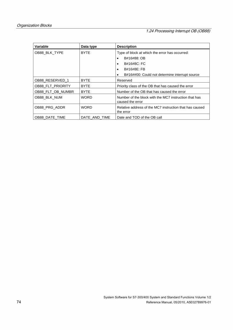
Organization Blocks 1.24 Processing Interrupt OB (OB88)
System Software for S7-300/400 System and Standard Functions Volume 1/2 74 Reference Manual, 05/2010, A5E02789976-01
Variable Data type Description
OB88_BLK_TYPE BYTE Type of block at which the error has occurred: • B#16#88: OB • B#16#8C: FC • B#16#8E: FB • B#16##00: Could not determine interrupt source
OB88_RESERVED_1 BYTE Reserved OB88_FLT_PRIORITY BYTE Priority class of the OB that has caused the error OB88_FLT_OB_NUMBR BYTE Number of the OB that has caused the error OB88_BLK_NUM WORD Number of the block with the MC7 instruction that has
caused the error OB88_PRG_ADDR WORD Relative address of the MC7 instruction that has caused
the error OB88_DATE_TIME DATE_AND_TIME Date and TOD of the OB call
Organization Blocks 1.25 Background Organization Block (OB90)
System Software for S7-300/400 System and Standard Functions Volume 1/2 Reference Manual, 05/2010, A5E02789976-01 75
1.25 Background Organization Block (OB90)
Description With STEP 7, you can monitor a maximum scan cycle time and can guarantee a minimum scan cycle time. If the execution time of OB1 including all the nested interrupts and system activities is less than the minimum scan cycle time that you have specified, the operating system reacts as follows:
• It calls the background OB (providing it exists on the CPU).
• It delays the next OB1 start (if OB90 does not exist on the CPU).
Understanding the Operation of the Background OB OB90 has the lowest priority of all OBs. It is interrupted by any system activity and any interrupt (even by OB1 after the minimum cycle time has elapsed) and is only resumed if the selected minimum scan cycle time has not yet been reached. The one exception to this is the execution of SFCs and SFBs that are started in OB90. These are executed with the priority of OB1 and are therefore not interrupted by OB1. There is no time monitoring of OB90.
The user program in OB90 is processed starting with the first instruction in the following situations:
• Following a warm, cold, or hot restart
• After loading or deleting a block (with STEP 7)
• After loading OB90 on the CPU in the RUN mode
• After terminating the background cycle
Note
With configurations in which there is no great difference between the minimum scan cycle time and the cycle monitoring time, SFC and SFB calls in the background OB can lead to the cycle time being exceeded unexpectedly.
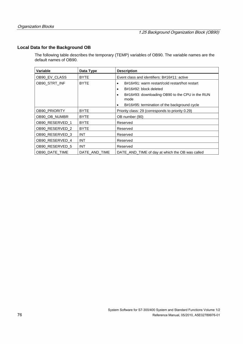
Organization Blocks 1.25 Background Organization Block (OB90)
System Software for S7-300/400 System and Standard Functions Volume 1/2 76 Reference Manual, 05/2010, A5E02789976-01
Local Data for the Background OB The following table describes the temporary (TEMP) variables of OB90. The variable names are the default names of OB90. Variable Data Type Description
OB90_EV_CLASS BYTE Event class and identifiers: B#16#11: active OB90_STRT_INF BYTE • B#16#91: warm restart/cold restart/hot restart
• B#16#92: block deleted • B#16#93: downloading OB90 to the CPU in the RUN
mode • B#16#95: termination of the background cycle
OB90_PRIORITY BYTE Priority class: 29 (corresponds to priority 0.29) OB90_OB_NUMBR BYTE OB number (90) OB90_RESERVED_1 BYTE Reserved OB90_RESERVED_2 BYTE Reserved OB90_RESERVED_3 INT Reserved OB90_RESERVED_4 INT Reserved OB90_RESERVED_5 INT Reserved OB90_DATE_TIME DATE_AND_TIME DATE_AND_TIME of day at which the OB was called
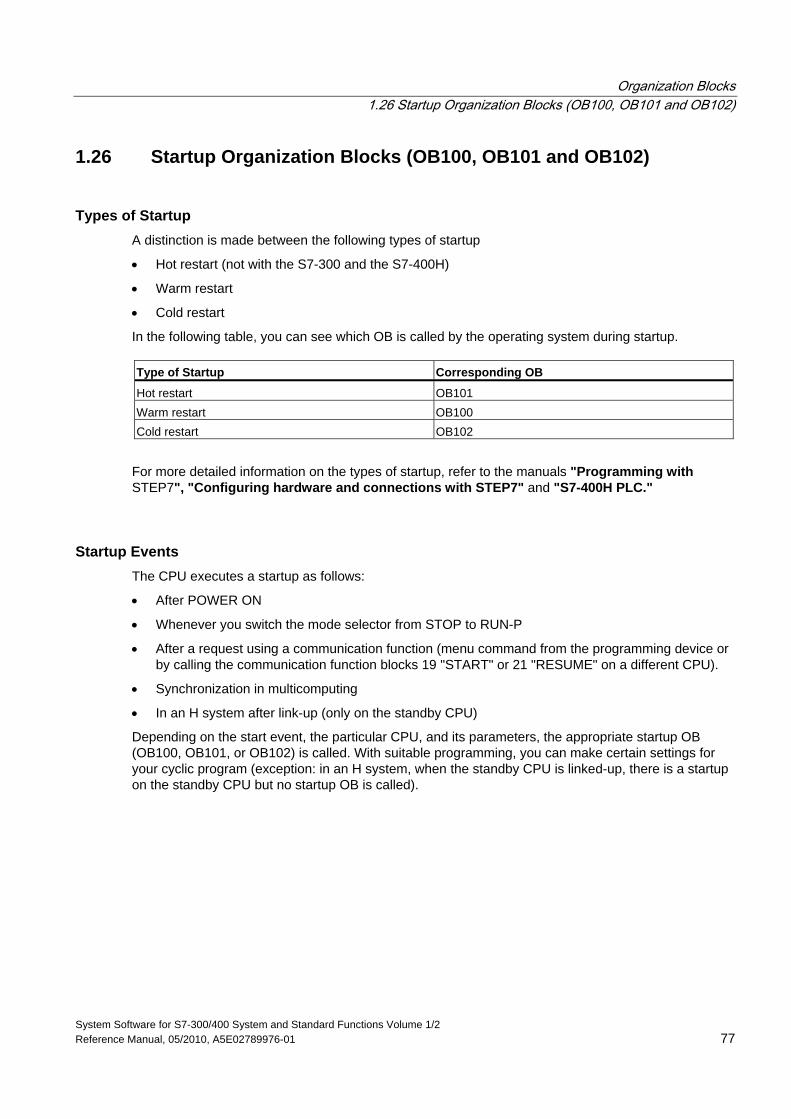
Organization Blocks 1.26 Startup Organization Blocks (OB100, OB101 and OB102)
System Software for S7-300/400 System and Standard Functions Volume 1/2 Reference Manual, 05/2010, A5E02789976-01 77
1.26 Startup Organization Blocks (OB100, OB101 and OB102)
Types of Startup A distinction is made between the following types of startup
• Hot restart (not with the S7-300 and the S7-400H)
• Warm restart
• Cold restart
In the following table, you can see which OB is called by the operating system during startup. Type of Startup Corresponding OB
Hot restart OB101 Warm restart OB100 Cold restart OB102
For more detailed information on the types of startup, refer to the manuals "Programming with STEP7", "Configuring hardware and connections with STEP7" and "S7-400H PLC."
Startup Events The CPU executes a startup as follows:
• After POWER ON
• Whenever you switch the mode selector from STOP to RUN-P
• After a request using a communication function (menu command from the programming device or by calling the communication function blocks 19 "START" or 21 "RESUME" on a different CPU).
• Synchronization in multicomputing
• In an H system after link-up (only on the standby CPU)
Depending on the start event, the particular CPU, and its parameters, the appropriate startup OB (OB100, OB101, or OB102) is called. With suitable programming, you can make certain settings for your cyclic program (exception: in an H system, when the standby CPU is linked-up, there is a startup on the standby CPU but no startup OB is called).
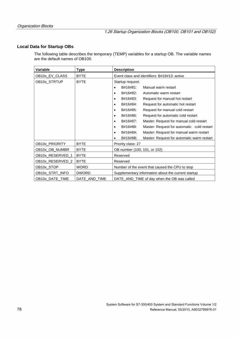
Organization Blocks 1.26 Startup Organization Blocks (OB100, OB101 and OB102)
System Software for S7-300/400 System and Standard Functions Volume 1/2 78 Reference Manual, 05/2010, A5E02789976-01
Local Data for Startup OBs The following table describes the temporary (TEMP) variables for a startup OB. The variable names are the default names of OB100. Variable Type Description
OB10x_EV_CLASS BYTE Event class and identifiers: B#16#13: active OB10x_STRTUP BYTE Startup request:
• B#16#81: Manual warm restart • B#16#82: Automatic warm restart • B#16#83: Request for manual hot restart • B#16#84: Request for automatic hot restart • B#16#85: Request for manual cold restart • B#16#86: Request for automatic cold restart • B#16#87: Master: Request for manual cold restart • B#16#88: Master: Request for automatic cold restart • B#16#8A: Master: Request for manual warm restart • B#16#8B: Master: Request for automatic warm restart
OB10x_PRIORITY BYTE Priority class: 27 OB10x_OB_NUMBR BYTE OB number (100, 101, or 102) OB10x_RESERVED_1 BYTE Reserved OB10x_RESERVED_2 BYTE Reserved OB10x_STOP WORD Number of the event that caused the CPU to stop OB10x_STRT_INFO DWORD Supplementary information about the current startup OB10x_DATE_TIME DATE_AND_TIME DATE_AND_TIME of day when the OB was called
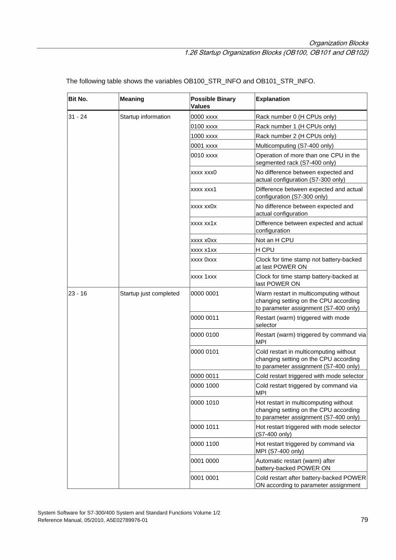
Organization Blocks 1.26 Startup Organization Blocks (OB100, OB101 and OB102)
System Software for S7-300/400 System and Standard Functions Volume 1/2 Reference Manual, 05/2010, A5E02789976-01 79
The following table shows the variables OB100_STR_INFO and OB101_STR_INFO. Bit No. Meaning Possible Binary
Values Explanation
0000 xxxx Rack number 0 (H CPUs only) 0100 xxxx Rack number 1 (H CPUs only) 1000 xxxx Rack number 2 (H CPUs only) 0001 xxxx Multicomputing (S7-400 only) 0010 xxxx Operation of more than one CPU in the
segmented rack (S7-400 only) xxxx xxx0 No difference between expected and
actual configuration (S7-300 only) xxxx xxx1 Difference between expected and actual
configuration (S7-300 only) xxxx xx0x No difference between expected and
actual configuration xxxx xx1x Difference between expected and actual
configuration xxxx x0xx Not an H CPU xxxx x1xx H CPU xxxx 0xxx Clock for time stamp not battery-backed
at last POWER ON
31 - 24 Startup information
xxxx 1xxx Clock for time stamp battery-backed at last POWER ON
0000 0001 Warm restart in multicomputing without changing setting on the CPU according to parameter assignment (S7-400 only)
0000 0011 Restart (warm) triggered with mode selector
0000 0100 Restart (warm) triggered by command via MPI
0000 0101 Cold restart in multicomputing without changing setting on the CPU according to parameter assignment (S7-400 only)
0000 0011 Cold restart triggered with mode selector 0000 1000 Cold restart triggered by command via
MPI 0000 1010 Hot restart in multicomputing without
changing setting on the CPU according to parameter assignment (S7-400 only)
0000 1011 Hot restart triggered with mode selector (S7-400 only)
0000 1100 Hot restart triggered by command via MPI (S7-400 only)
0001 0000 Automatic restart (warm) after battery-backed POWER ON
23 - 16 Startup just completed
0001 0001 Cold restart after battery-backed POWER ON according to parameter assignment
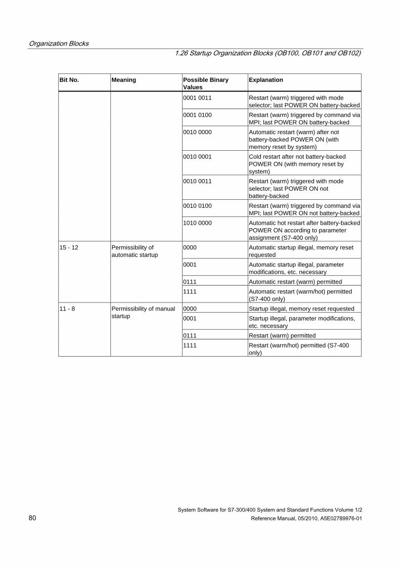
Organization Blocks 1.26 Startup Organization Blocks (OB100, OB101 and OB102)
System Software for S7-300/400 System and Standard Functions Volume 1/2 80 Reference Manual, 05/2010, A5E02789976-01
Bit No. Meaning Possible Binary Values
Explanation
0001 0011 Restart (warm) triggered with mode selector; last POWER ON battery-backed
0001 0100 Restart (warm) triggered by command via MPI; last POWER ON battery-backed
0010 0000 Automatic restart (warm) after not battery-backed POWER ON (with memory reset by system)
0010 0001 Cold restart after not battery-backed POWER ON (with memory reset by system)
0010 0011 Restart (warm) triggered with mode selector; last POWER ON not battery-backed
0010 0100 Restart (warm) triggered by command via MPI; last POWER ON not battery-backed
1010 0000 Automatic hot restart after battery-backed POWER ON according to parameter assignment (S7-400 only)
0000 Automatic startup illegal, memory reset requested
0001 Automatic startup illegal, parameter modifications, etc. necessary
0111 Automatic restart (warm) permitted
15 - 12 Permissibility of automatic startup
1111 Automatic restart (warm/hot) permitted (S7-400 only)
0000 Startup illegal, memory reset requested 0001 Startup illegal, parameter modifications,
etc. necessary 0111 Restart (warm) permitted
11 - 8 Permissibility of manual startup
1111 Restart (warm/hot) permitted (S7-400 only)
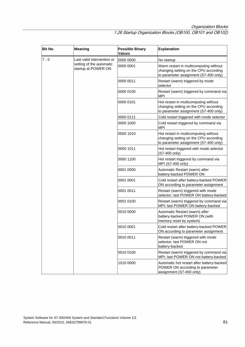
Organization Blocks 1.26 Startup Organization Blocks (OB100, OB101 and OB102)
System Software for S7-300/400 System and Standard Functions Volume 1/2 Reference Manual, 05/2010, A5E02789976-01 81
Bit No. Meaning Possible Binary Values
Explanation
0000 0000 No startup 0000 0001 Warm restart in multicomputing without
changing setting on the CPU according to parameter assignment (S7-400 only)
0000 0011 Restart (warm) triggered by mode selector
0000 0100 Restart (warm) triggered by command via MPI
0000 0101 Hot restart in multicomputing without changing setting on the CPU according to parameter assignment (S7-400 only)
0000 0111 Cold restart triggered with mode selector0000 1000 Cold restart triggered by command via
MPI 0000 1010 Hot restart in multicomputing without
changing setting on the CPU according to parameter assignment (S7-400 only)
0000 1011 Hot restart triggered with mode selector (S7-400 only)
0000 1100 Hot restart triggered by command via MPI (S7-400 only)
0001 0000 Automatic Restart (warm) after battery-backed POWER ON
0001 0001 Cold restart after battery-backed POWER ON according to parameter assignment
0001 0011 Restart (warm) triggered with mode selector; last POWER ON battery-backed
0001 0100 Restart (warm) triggered by command via MPI; last POWER ON battery-backed
0010 0000 Automatic Restart (warm) after battery-backed POWER ON (with memory reset by system)
0010 0001 Cold restart after battery-backed POWER ON according to parameter assignment
0010 0011 Restart (warm) triggered with mode selector; last POWER ON not battery-backed
0010 0100 Restart (warm) triggered by command via MPI; last POWER ON not battery-backed
7 - 0 Last valid intervention or setting of the automatic startup at POWER ON
1010 0000 Automatic hot restart after battery-backed POWER ON according to parameter assignment (S7-400 only)
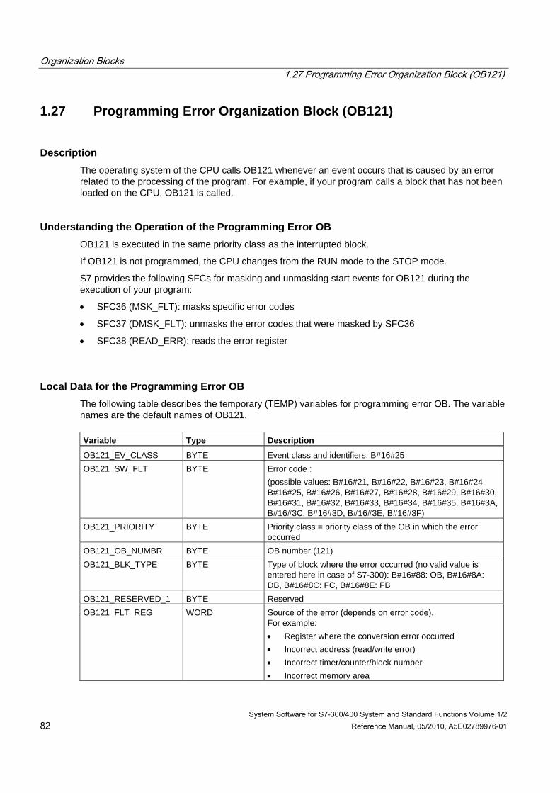
Organization Blocks 1.27 Programming Error Organization Block (OB121)
System Software for S7-300/400 System and Standard Functions Volume 1/2 82 Reference Manual, 05/2010, A5E02789976-01
1.27 Programming Error Organization Block (OB121)
Description The operating system of the CPU calls OB121 whenever an event occurs that is caused by an error related to the processing of the program. For example, if your program calls a block that has not been loaded on the CPU, OB121 is called.
Understanding the Operation of the Programming Error OB OB121 is executed in the same priority class as the interrupted block.
If OB121 is not programmed, the CPU changes from the RUN mode to the STOP mode.
S7 provides the following SFCs for masking and unmasking start events for OB121 during the execution of your program:
• SFC36 (MSK_FLT): masks specific error codes
• SFC37 (DMSK_FLT): unmasks the error codes that were masked by SFC36
• SFC38 (READ_ERR): reads the error register
Local Data for the Programming Error OB The following table describes the temporary (TEMP) variables for programming error OB. The variable names are the default names of OB121. Variable Type Description
OB121_EV_CLASS BYTE Event class and identifiers: B#16#25 OB121_SW_FLT BYTE Error code :
(possible values: B#16#21, B#16#22, B#16#23, B#16#24, B#16#25, B#16#26, B#16#27, B#16#28, B#16#29, B#16#30, B#16#31, B#16#32, B#16#33, B#16#34, B#16#35, B#16#3A, B#16#3C, B#16#3D, B#16#3E, B#16#3F)
OB121_PRIORITY BYTE Priority class = priority class of the OB in which the error occurred
OB121_OB_NUMBR BYTE OB number (121) OB121_BLK_TYPE BYTE Type of block where the error occurred (no valid value is
entered here in case of S7-300): B#16#88: OB, B#16#8A: DB, B#16#8C: FC, B#16#8E: FB
OB121_RESERVED_1 BYTE Reserved OB121_FLT_REG WORD Source of the error (depends on error code).
For example: • Register where the conversion error occurred • Incorrect address (read/write error) • Incorrect timer/counter/block number • Incorrect memory area
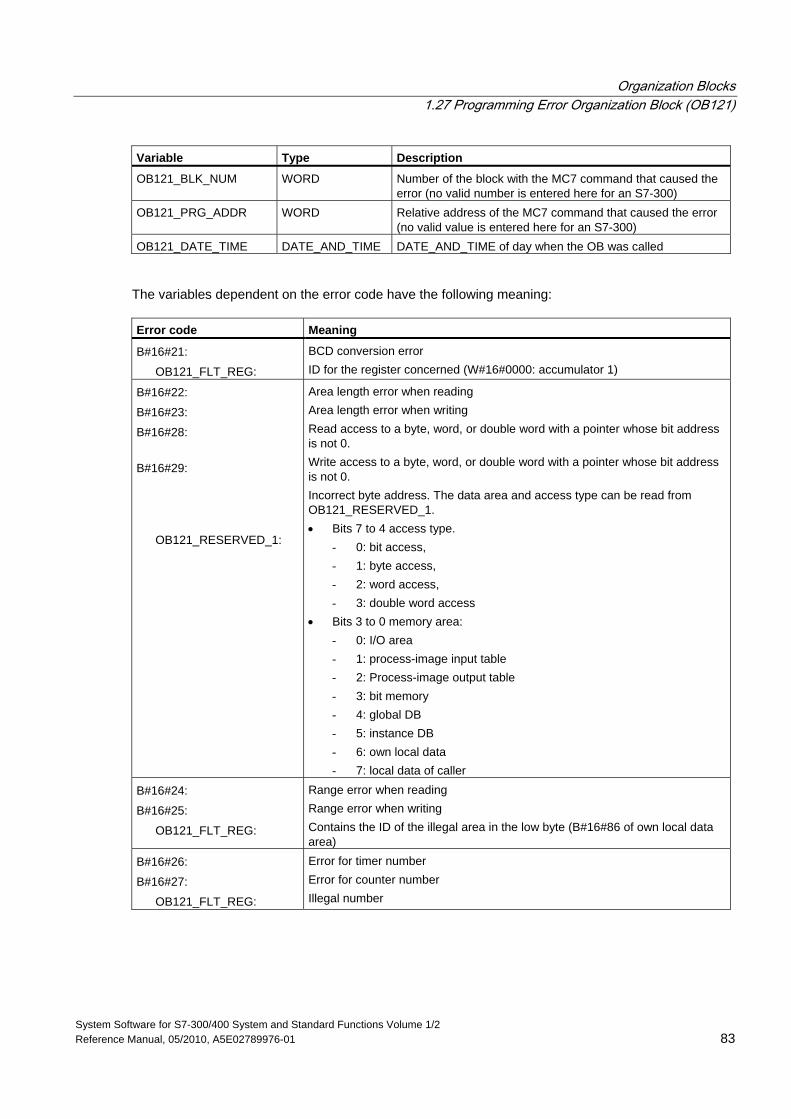
Organization Blocks 1.27 Programming Error Organization Block (OB121)
System Software for S7-300/400 System and Standard Functions Volume 1/2 Reference Manual, 05/2010, A5E02789976-01 83
Variable Type Description
OB121_BLK_NUM WORD Number of the block with the MC7 command that caused the error (no valid number is entered here for an S7-300)
OB121_PRG_ADDR WORD Relative address of the MC7 command that caused the error (no valid value is entered here for an S7-300)
OB121_DATE_TIME DATE_AND_TIME DATE_AND_TIME of day when the OB was called
The variables dependent on the error code have the following meaning: Error code Meaning
B#16#21:
OB121_FLT_REG:
BCD conversion error ID for the register concerned (W#16#0000: accumulator 1)
B#16#22:
B#16#23:
B#16#28:
B#16#29:
OB121_RESERVED_1:
Area length error when reading Area length error when writing Read access to a byte, word, or double word with a pointer whose bit address is not 0. Write access to a byte, word, or double word with a pointer whose bit address is not 0. Incorrect byte address. The data area and access type can be read from OB121_RESERVED_1. • Bits 7 to 4 access type.
- 0: bit access, - 1: byte access, - 2: word access, - 3: double word access
• Bits 3 to 0 memory area: - 0: I/O area - 1: process-image input table - 2: Process-image output table - 3: bit memory - 4: global DB - 5: instance DB - 6: own local data - 7: local data of caller
B#16#24:
B#16#25:
OB121_FLT_REG:
Range error when reading Range error when writing Contains the ID of the illegal area in the low byte (B#16#86 of own local data area)
B#16#26:
B#16#27:
OB121_FLT_REG:
Error for timer number Error for counter number Illegal number
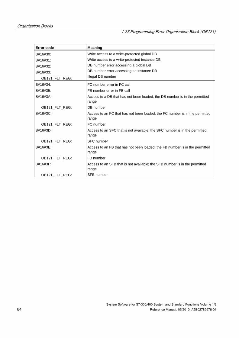
Organization Blocks 1.27 Programming Error Organization Block (OB121)
System Software for S7-300/400 System and Standard Functions Volume 1/2 84 Reference Manual, 05/2010, A5E02789976-01
Error code Meaning
B#16#30:
B#16#31:
B#16#32:
B#16#33:
OB121_FLT_REG:
Write access to a write-protected global DB Write access to a write-protected instance DB DB number error accessing a global DB DB number error accessing an instance DB Illegal DB number
B#16#34:
B#16#35:
B#16#3A:
OB121_FLT_REG:
B#16#3C:
OB121_FLT_REG:
B#16#3D:
OB121_FLT_REG:
B#16#3E:
OB121_FLT_REG:
B#16#3F:
OB121_FLT_REG:
FC number error in FC call
FB number error in FB call
Access to a DB that has not been loaded; the DB number is in the permitted range
DB number
Access to an FC that has not been loaded; the FC number is in the permitted range
FC number
Access to an SFC that is not available; the SFC number is in the permitted range
SFC number
Access to an FB that has not been loaded; the FB number is in the permitted range
FB number
Access to an SFB that is not available; the SFB number is in the permitted range SFB number
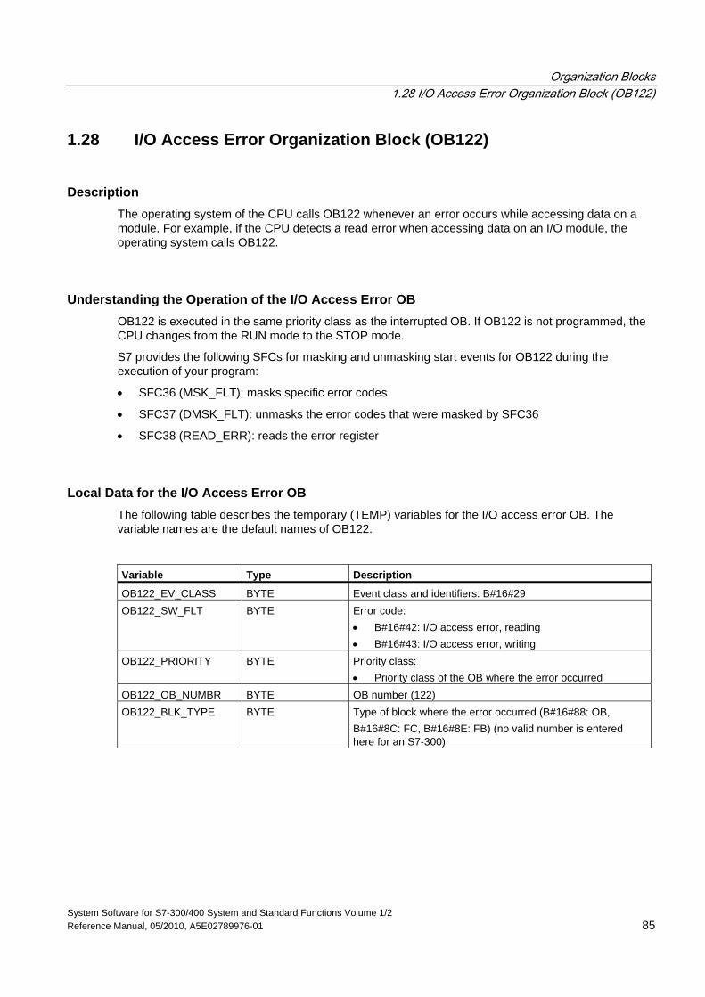
Organization Blocks 1.28 I/O Access Error Organization Block (OB122)
System Software for S7-300/400 System and Standard Functions Volume 1/2 Reference Manual, 05/2010, A5E02789976-01 85
1.28 I/O Access Error Organization Block (OB122)
Description The operating system of the CPU calls OB122 whenever an error occurs while accessing data on a module. For example, if the CPU detects a read error when accessing data on an I/O module, the operating system calls OB122.
Understanding the Operation of the I/O Access Error OB OB122 is executed in the same priority class as the interrupted OB. If OB122 is not programmed, the CPU changes from the RUN mode to the STOP mode.
S7 provides the following SFCs for masking and unmasking start events for OB122 during the execution of your program:
• SFC36 (MSK_FLT): masks specific error codes
• SFC37 (DMSK_FLT): unmasks the error codes that were masked by SFC36
• SFC38 (READ_ERR): reads the error register
Local Data for the I/O Access Error OB The following table describes the temporary (TEMP) variables for the I/O access error OB. The variable names are the default names of OB122. Variable Type Description
OB122_EV_CLASS BYTE Event class and identifiers: B#16#29 OB122_SW_FLT BYTE Error code:
• B#16#42: I/O access error, reading • B#16#43: I/O access error, writing
OB122_PRIORITY BYTE Priority class: • Priority class of the OB where the error occurred
OB122_OB_NUMBR BYTE OB number (122) OB122_BLK_TYPE BYTE Type of block where the error occurred (B#16#88: OB,
B#16#8C: FC, B#16#8E: FB) (no valid number is entered here for an S7-300)
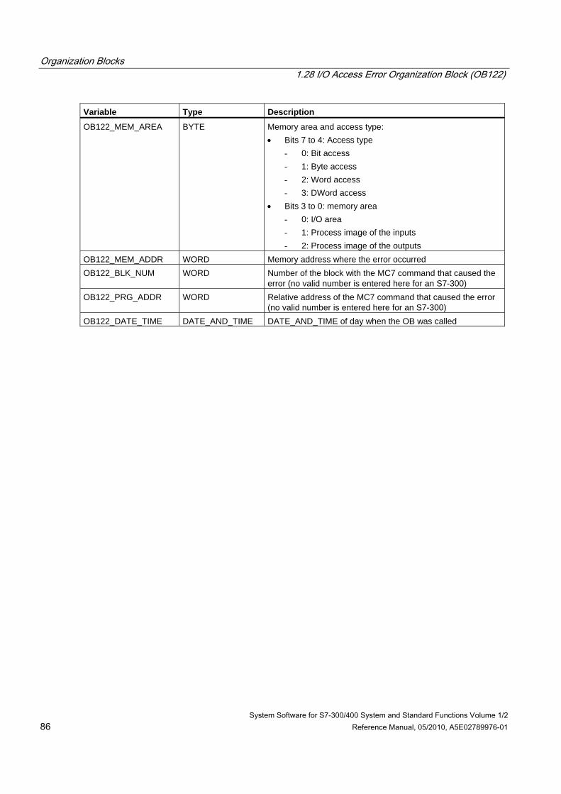
Organization Blocks 1.28 I/O Access Error Organization Block (OB122)
System Software for S7-300/400 System and Standard Functions Volume 1/2 86 Reference Manual, 05/2010, A5E02789976-01
Variable Type Description
OB122_MEM_AREA BYTE Memory area and access type: • Bits 7 to 4: Access type
- 0: Bit access - 1: Byte access - 2: Word access - 3: DWord access
• Bits 3 to 0: memory area - 0: I/O area - 1: Process image of the inputs - 2: Process image of the outputs
OB122_MEM_ADDR WORD Memory address where the error occurred OB122_BLK_NUM WORD Number of the block with the MC7 command that caused the
error (no valid number is entered here for an S7-300) OB122_PRG_ADDR WORD Relative address of the MC7 command that caused the error
(no valid number is entered here for an S7-300) OB122_DATE_TIME DATE_AND_TIME DATE_AND_TIME of day when the OB was called
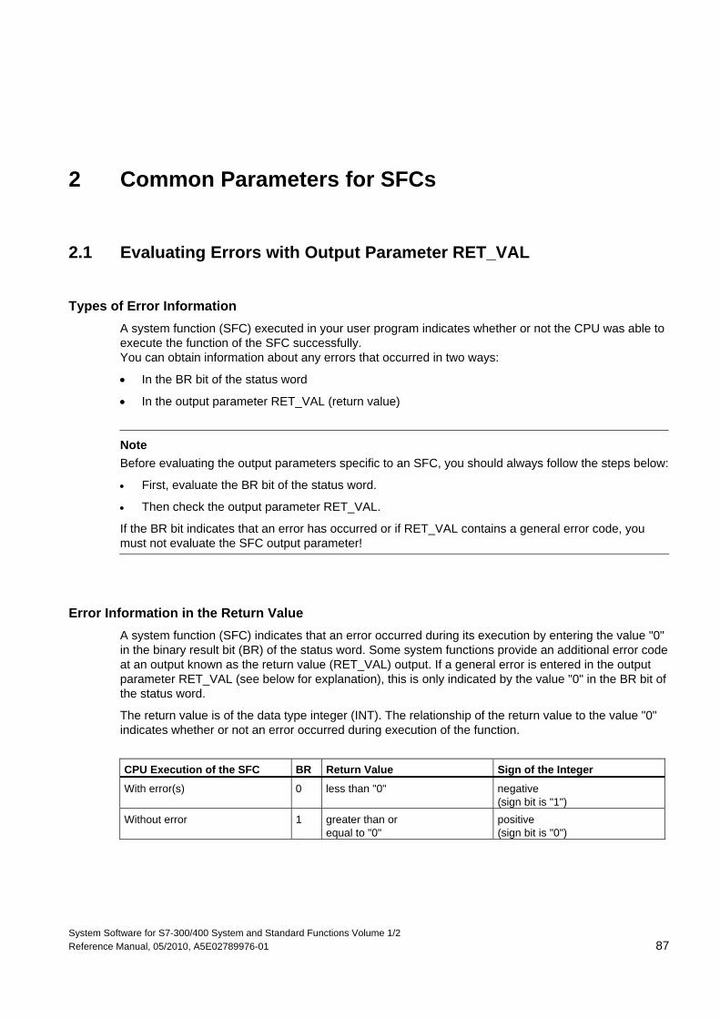
System Software for S7-300/400 System and Standard Functions Volume 1/2 Reference Manual, 05/2010, A5E02789976-01 87
2 Common Parameters for SFCs
2.1 Evaluating Errors with Output Parameter RET_VAL
Types of Error Information A system function (SFC) executed in your user program indicates whether or not the CPU was able to execute the function of the SFC successfully. You can obtain information about any errors that occurred in two ways:
• In the BR bit of the status word
• In the output parameter RET_VAL (return value)
Note
Before evaluating the output parameters specific to an SFC, you should always follow the steps below:
• First, evaluate the BR bit of the status word.
• Then check the output parameter RET_VAL.
If the BR bit indicates that an error has occurred or if RET_VAL contains a general error code, you must not evaluate the SFC output parameter!
Error Information in the Return Value A system function (SFC) indicates that an error occurred during its execution by entering the value "0" in the binary result bit (BR) of the status word. Some system functions provide an additional error code at an output known as the return value (RET_VAL) output. If a general error is entered in the output parameter RET_VAL (see below for explanation), this is only indicated by the value "0" in the BR bit of the status word.
The return value is of the data type integer (INT). The relationship of the return value to the value "0" indicates whether or not an error occurred during execution of the function.
CPU Execution of the SFC BR Return Value Sign of the Integer
With error(s) 0 less than "0" negative (sign bit is "1")
Without error 1 greater than or equal to "0"
positive (sign bit is "0")
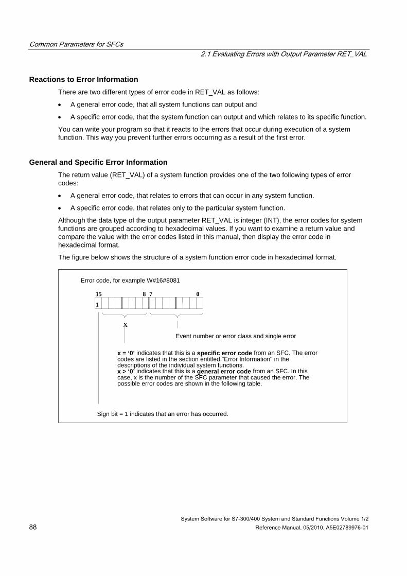
Common Parameters for SFCs 2.1 Evaluating Errors with Output Parameter RET_VAL
System Software for S7-300/400 System and Standard Functions Volume 1/2 88 Reference Manual, 05/2010, A5E02789976-01
Reactions to Error Information There are two different types of error code in RET_VAL as follows:
• A general error code, that all system functions can output and
• A specific error code, that the system function can output and which relates to its specific function.
You can write your program so that it reacts to the errors that occur during execution of a system function. This way you prevent further errors occurring as a result of the first error.
General and Specific Error Information The return value (RET_VAL) of a system function provides one of the two following types of error codes:
• A general error code, that relates to errors that can occur in any system function.
• A specific error code, that relates only to the particular system function.
Although the data type of the output parameter RET_VAL is integer (INT), the error codes for system functions are grouped according to hexadecimal values. If you want to examine a return value and compare the value with the error codes listed in this manual, then display the error code in hexadecimal format.
The figure below shows the structure of a system function error code in hexadecimal format.
Error code, for example W#16#8081
Sign bit = 1 indicates that an error has occurred.
15 8 7 0
1
X
Event number or error class and single error
x = ‘0’ indicates that this is a specific error code from an SFC. The errorcodes are listed in the section entitled "Error Information" in thedescriptions of the individual system functions.x > ‘0’ indicates that this is a general error code from an SFC. In thiscase, x is the number of the SFC parameter that caused the error. Thepossible error codes are shown in the following table.
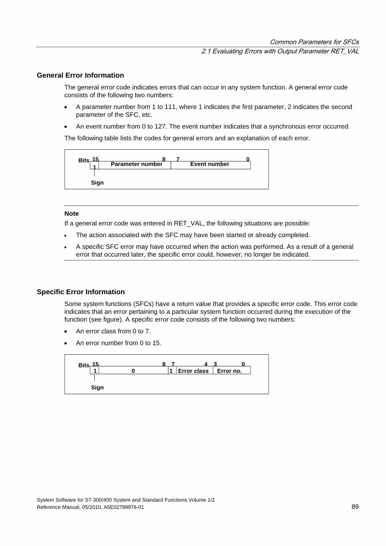
Common Parameters for SFCs 2.1 Evaluating Errors with Output Parameter RET_VAL
System Software for S7-300/400 System and Standard Functions Volume 1/2 Reference Manual, 05/2010, A5E02789976-01 89
General Error Information The general error code indicates errors that can occur in any system function. A general error code consists of the following two numbers:
• A parameter number from 1 to 111, where 1 indicates the first parameter, 2 indicates the second parameter of the SFC, etc.
• An event number from 0 to 127. The event number indicates that a synchronous error occurred.
The following table lists the codes for general errors and an explanation of each error.
07815Bits
Sign
Event numberParameter number1
Note
If a general error code was entered in RET_VAL, the following situations are possible:
• The action associated with the SFC may have been started or already completed.
• A specific SFC error may have occurred when the action was performed. As a result of a general error that occurred later, the specific error could, however, no longer be indicated.
Specific Error Information Some system functions (SFCs) have a return value that provides a specific error code. This error code indicates that an error pertaining to a particular system function occurred during the execution of the function (see figure). A specific error code consists of the following two numbers:
• An error class from 0 to 7.
• An error number from 0 to 15.
07815Bits
Sign
Error no.Error class134
0 1
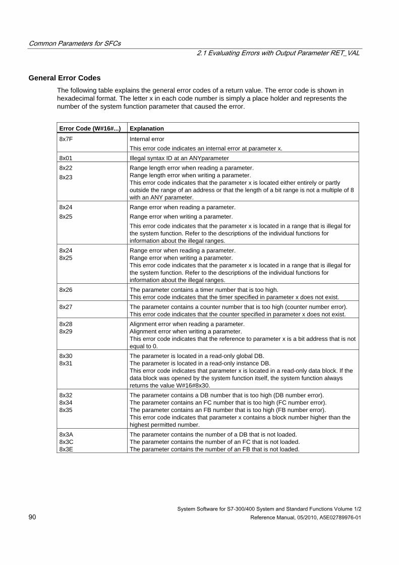
Common Parameters for SFCs 2.1 Evaluating Errors with Output Parameter RET_VAL
System Software for S7-300/400 System and Standard Functions Volume 1/2 90 Reference Manual, 05/2010, A5E02789976-01
General Error Codes The following table explains the general error codes of a return value. The error code is shown in hexadecimal format. The letter x in each code number is simply a place holder and represents the number of the system function parameter that caused the error.
Error Code (W#16#...) Explanation
8x7F Internal error This error code indicates an internal error at parameter x.
8x01 Illegal syntax ID at an ANYparameter 8x22 8x23
Range length error when reading a parameter. Range length error when writing a parameter. This error code indicates that the parameter x is located either entirely or partly outside the range of an address or that the length of a bit range is not a multiple of 8 with an ANY parameter.
8x24 8x25
Range error when reading a parameter. Range error when writing a parameter. This error code indicates that the parameter x is located in a range that is illegal for the system function. Refer to the descriptions of the individual functions for information about the illegal ranges.
8x24 8x25
Range error when reading a parameter. Range error when writing a parameter. This error code indicates that the parameter x is located in a range that is illegal for the system function. Refer to the descriptions of the individual functions for information about the illegal ranges.
8x26 The parameter contains a timer number that is too high. This error code indicates that the timer specified in parameter x does not exist.
8x27 The parameter contains a counter number that is too high (counter number error). This error code indicates that the counter specified in parameter x does not exist.
8x28 8x29
Alignment error when reading a parameter. Alignment error when writing a parameter. This error code indicates that the reference to parameter x is a bit address that is not equal to 0.
8x30 8x31
The parameter is located in a read-only global DB. The parameter is located in a read-only instance DB. This error code indicates that parameter x is located in a read-only data block. If the data block was opened by the system function itself, the system function always returns the value W#16#8x30.
8x32 8x34 8x35
The parameter contains a DB number that is too high (DB number error). The parameter contains an FC number that is too high (FC number error). The parameter contains an FB number that is too high (FB number error). This error code indicates that parameter x contains a block number higher than the highest permitted number.
8x3A 8x3C 8x3E
The parameter contains the number of a DB that is not loaded. The parameter contains the number of an FC that is not loaded. The parameter contains the number of an FB that is not loaded.
Common Parameters for SFCs 2.1 Evaluating Errors with Output Parameter RET_VAL
System Software for S7-300/400 System and Standard Functions Volume 1/2 Reference Manual, 05/2010, A5E02789976-01 91
Error Code (W#16#...) Explanation
8x42 8x43
An access error occurred while the system was attempting to read a parameter from the peripheral input area. An access error occurred while the system was attempting to write a parameter to the peripheral output area.
8x44 8x45
Error in the nth (n > 1) read access after an error occurred. Error in the nth (n > 1) write access after an error occurred. This error code indicates that access to the required parameter is denied.
Common Parameters for SFCs 2.2 Meaning of the Parameters REQ, RET_VAL and BUSY with Asynchronous SFCs
System Software for S7-300/400 System and Standard Functions Volume 1/2 92 Reference Manual, 05/2010, A5E02789976-01
2.2 Meaning of the Parameters REQ, RET_VAL and BUSY with Asynchronous SFCs
Asynchronous SFCs SFCs that operate asynchronously are SFCs that are called more than once before they complete their functions. The following SFCs are either always executed asynchronously or in certain situations:
• SFC 7 "DP_PRAL"
• SFC 11 "DPSYC_FR"
• SFC 12 "D_ACT_DP"
• SFC 13 "DPNRM_DG"
• SFC 51 "RDSYSST"
• SFC 55 "WR_PARM"
• SFC 56 "WR_DPARM"
• SFC 57 "PARM_MOD"
• SFC 58 "WR_REC"
• SFC 59 "RD_REC"
• SFC 65 "X_SEND"
• SFC 67 "X_GET"
• SFC 68 "X_PUT"
• SFC 69 "X_ABORT"
• SFC 72 "I_GET"
• SFC 73 "I_PUT"
• SFC 74 "I_ABORT"
• SFC 82 "CREA_DBL"
• SFC 83 "READ_DBL"
• SFC 84 "WRIT_DBL"
• SFC 90 "H_CTRL"
• SFC 102 "RD_DPARA"
• SFC 103 "DP_TOPOL"
• SFC 114 "PN_DP"
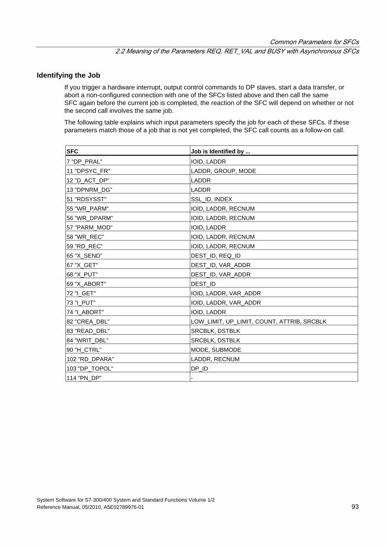
Common Parameters for SFCs 2.2 Meaning of the Parameters REQ, RET_VAL and BUSY with Asynchronous SFCs
System Software for S7-300/400 System and Standard Functions Volume 1/2 Reference Manual, 05/2010, A5E02789976-01 93
Identifying the Job If you trigger a hardware interrupt, output control commands to DP slaves, start a data transfer, or abort a non-configured connection with one of the SFCs listed above and then call the same SFC again before the current job is completed, the reaction of the SFC will depend on whether or not the second call involves the same job.
The following table explains which input parameters specify the job for each of these SFCs. If these parameters match those of a job that is not yet completed, the SFC call counts as a follow-on call.
SFC Job is Identified by ...
7 "DP_PRAL" IOID, LADDR 11 "DPSYC_FR" LADDR, GROUP, MODE 12 "D_ACT_DP" LADDR 13 "DPNRM_DG" LADDR 51 "RDSYSST" SSL_ID, INDEX 55 "WR_PARM" IOID, LADDR, RECNUM 56 "WR_DPARM" IOID, LADDR, RECNUM 57 "PARM_MOD" IOID, LADDR 58 "WR_REC" IOID, LADDR, RECNUM 59 "RD_REC" IOID, LADDR, RECNUM 65 "X_SEND" DEST_ID, REQ_ID 67 "X_GET" DEST_ID, VAR_ADDR 68 "X_PUT" DEST_ID, VAR_ADDR 69 "X_ABORT" DEST_ID 72 "I_GET" IOID, LADDR, VAR_ADDR 73 "I_PUT" IOID, LADDR, VAR_ADDR 74 "I_ABORT" IOID, LADDR 82 "CREA_DBL" LOW_LIMIT, UP_LIMIT, COUNT, ATTRIB, SRCBLK 83 "READ_DBL" SRCBLK, DSTBLK 84 "WRIT_DBL" SRCBLK, DSTBLK 90 "H_CTRL" MODE, SUBMODE 102 "RD_DPARA" LADDR, RECNUM 103 "DP_TOPOL" DP_ID 114 "PN_DP" -
Common Parameters for SFCs 2.2 Meaning of the Parameters REQ, RET_VAL and BUSY with Asynchronous SFCs
System Software for S7-300/400 System and Standard Functions Volume 1/2 94 Reference Manual, 05/2010, A5E02789976-01
Input Parameter REQ The REQ (request) input parameter is used solely to start the job:
• If you call the SFC for a job that is not currently active, the job is started by REQ = 1 (situation 1).
• If a particular job has been started and not yet completed and you call the SFC again to perform the same job (for example, in a cyclic interrupt OB), then REQ is not evaluated by the SFC (situation 2).
Output Parameters RET_VAL and BUSY The status of the job execution is indicated by the output parameters RET_VAL and BUSY.
Refer also to the note in Evaluating Errors with the Output Parameter RET_VAL.
• In Case 1 (first call with REQ=1), W#16#7001 is entered in RET_VAL if system resources are free and the input parameters are correct. BUSY is then set. If the required system resources are currently being used or the input parameters have errors, the corresponding error code is entered in RET_VAL and BUSY has the value 0.
• In Case 2 (call while the same job is active), W#16#7002 is entered in RET_VAL (this is a warning that the job is still being processed), and BUSY is set.
• The following applies to the last call for a job:
- With SFC 13 "DPNRM_DG," SFC 67 "X_GET" and SFC 72 "I_GET" the number of supplied data is entered in RET_VAL as a positive number of bytes if no error occurred. BUSY then has the value 0. If an error occurs, RET_VAL contains the error information. You must not evaluate BUSY in this case.
- With SFC 59 "RD_REC" the size of the data record in bytes is entered in RET_VAL or the value 0 if no error occurred (refer to Reading a Data Record with the SFC 59 "RD_REC" !). In this case, BUSY has the value 0. If an error occurs, the error code is entered in RET_VAL and BUSY has the value 0.)
- With all other SFCs, if the job was executed error-free, 0 is entered in RET_VAL, and BUSY has the value 0. If an error occurs, the error code is entered in RET_VAL and BUSY has the value 0.
Note
If the first and last call come together, the reaction is the same for RET_VAL and BUSY as described for the last call.
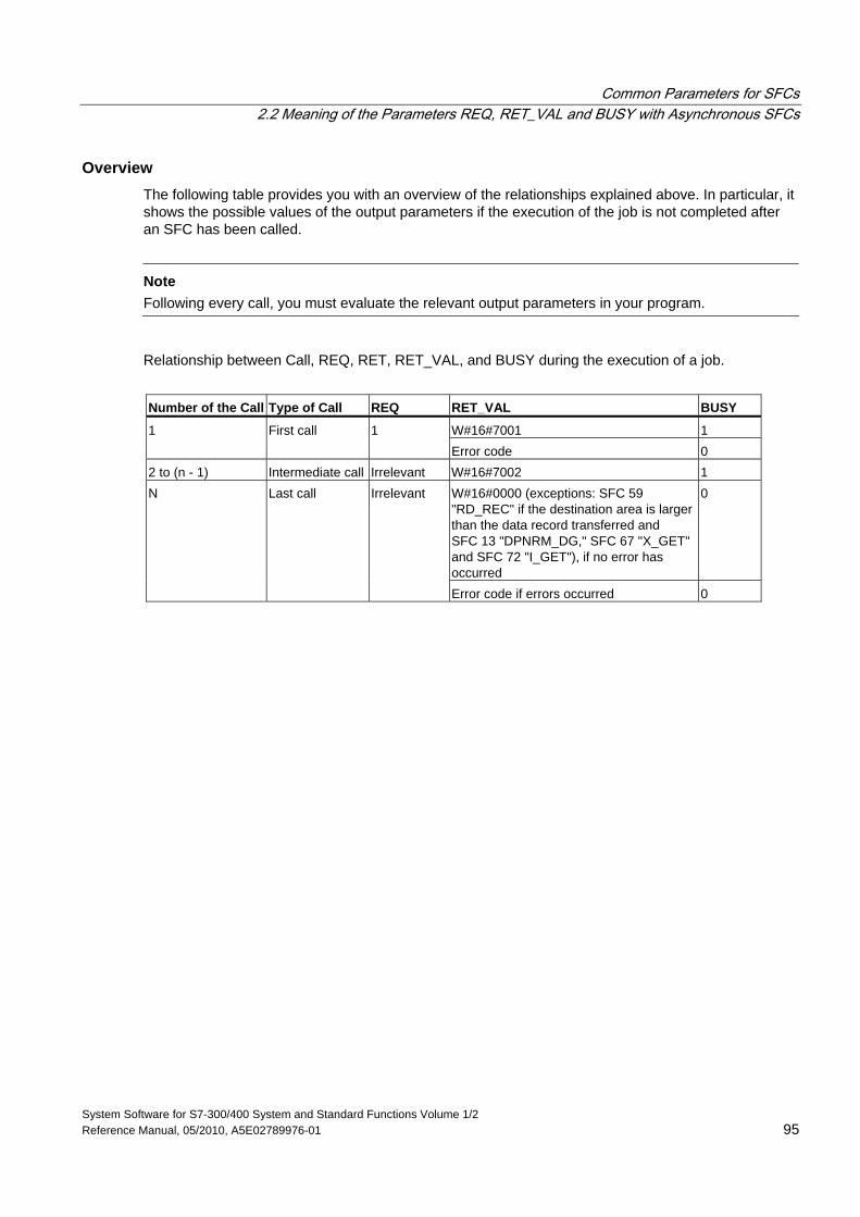
Common Parameters for SFCs 2.2 Meaning of the Parameters REQ, RET_VAL and BUSY with Asynchronous SFCs
System Software for S7-300/400 System and Standard Functions Volume 1/2 Reference Manual, 05/2010, A5E02789976-01 95
Overview The following table provides you with an overview of the relationships explained above. In particular, it shows the possible values of the output parameters if the execution of the job is not completed after an SFC has been called.
Note
Following every call, you must evaluate the relevant output parameters in your program.
Relationship between Call, REQ, RET, RET_VAL, and BUSY during the execution of a job.
Number of the Call Type of Call REQ RET_VAL BUSY
W#16#7001 1 1 First call 1 Error code 0
2 to (n - 1) Intermediate call Irrelevant W#16#7002 1 W#16#0000 (exceptions: SFC 59 "RD_REC" if the destination area is larger than the data record transferred and SFC 13 "DPNRM_DG," SFC 67 "X_GET" and SFC 72 "I_GET"), if no error has occurred
0 N Last call Irrelevant
Error code if errors occurred 0
Common Parameters for SFCs 2.2 Meaning of the Parameters REQ, RET_VAL and BUSY with Asynchronous SFCs
System Software for S7-300/400 System and Standard Functions Volume 1/2 96 Reference Manual, 05/2010, A5E02789976-01
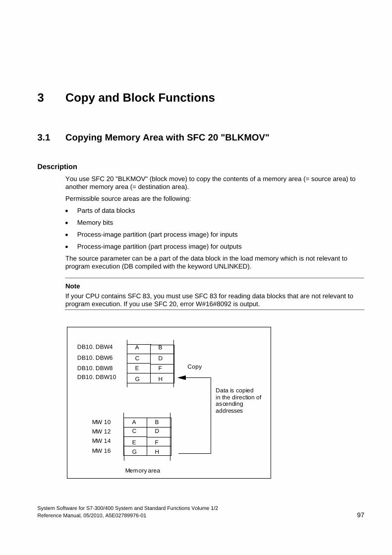
System Software for S7-300/400 System and Standard Functions Volume 1/2 Reference Manual, 05/2010, A5E02789976-01 97
3 Copy and Block Functions
3.1 Copying Memory Area with SFC 20 "BLKMOV"
Description You use SFC 20 "BLKMOV" (block move) to copy the contents of a memory area (= source area) to another memory area (= destination area).
Permissible source areas are the following:
• Parts of data blocks
• Memory bits
• Process-image partition (part process image) for inputs
• Process-image partition (part process image) for outputs
The source parameter can be a part of the data block in the load memory which is not relevant to program execution (DB compiled with the keyword UNLINKED).
Note If your CPU contains SFC 83, you must use SFC 83 for reading data blocks that are not relevant to program execution. If you use SFC 20, error W#16#8092 is output.
Data is copiedin the direction ofascendingaddresses
Memory area
Copy
DB10. DBW4
DB10. DBW6
DB10. DBW8DB10. DBW10
MW 10MW 12MW 14
MW 16
A B
C D
E F
G H
A BC D
E FG H
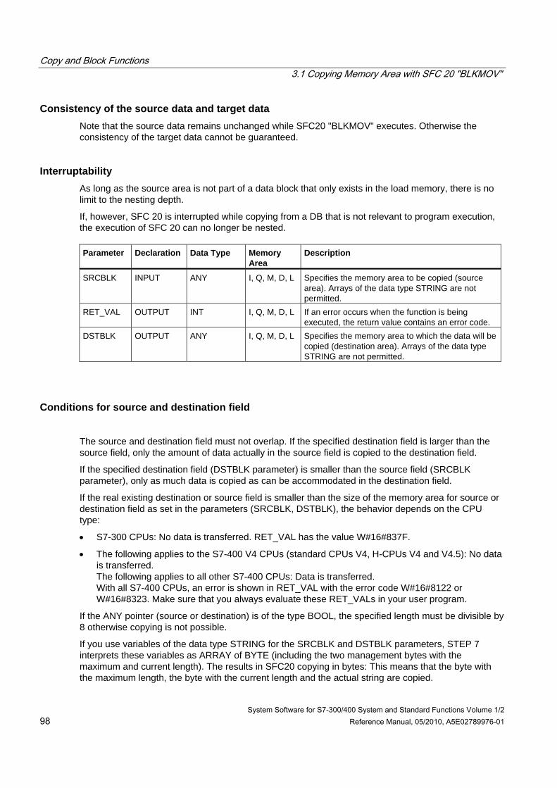
Copy and Block Functions 3.1 Copying Memory Area with SFC 20 "BLKMOV"
System Software for S7-300/400 System and Standard Functions Volume 1/2 98 Reference Manual, 05/2010, A5E02789976-01
Consistency of the source data and target data Note that the source data remains unchanged while SFC20 "BLKMOV" executes. Otherwise the consistency of the target data cannot be guaranteed.
Interruptability As long as the source area is not part of a data block that only exists in the load memory, there is no limit to the nesting depth.
If, however, SFC 20 is interrupted while copying from a DB that is not relevant to program execution, the execution of SFC 20 can no longer be nested. Parameter
Declaration
Data Type
Memory Area
Description
SRCBLK INPUT ANY I, Q, M, D, L Specifies the memory area to be copied (source area). Arrays of the data type STRING are not permitted.
RET_VAL OUTPUT INT I, Q, M, D, L If an error occurs when the function is being executed, the return value contains an error code.
DSTBLK OUTPUT ANY I, Q, M, D, L Specifies the memory area to which the data will be copied (destination area). Arrays of the data type STRING are not permitted.
Conditions for source and destination field
The source and destination field must not overlap. If the specified destination field is larger than the source field, only the amount of data actually in the source field is copied to the destination field.
If the specified destination field (DSTBLK parameter) is smaller than the source field (SRCBLK parameter), only as much data is copied as can be accommodated in the destination field.
If the real existing destination or source field is smaller than the size of the memory area for source or destination field as set in the parameters (SRCBLK, DSTBLK), the behavior depends on the CPU type:
• S7-300 CPUs: No data is transferred. RET_VAL has the value W#16#837F.
• The following applies to the S7-400 V4 CPUs (standard CPUs V4, H-CPUs V4 and V4.5): No data is transferred. The following applies to all other S7-400 CPUs: Data is transferred. With all S7-400 CPUs, an error is shown in RET_VAL with the error code W#16#8122 or W#16#8323. Make sure that you always evaluate these RET_VALs in your user program.
If the ANY pointer (source or destination) is of the type BOOL, the specified length must be divisible by 8 otherwise copying is not possible.
If you use variables of the data type STRING for the SRCBLK and DSTBLK parameters, STEP 7 interprets these variables as ARRAY of BYTE (including the two management bytes with the maximum and current length). The results in SFC20 copying in bytes: This means that the byte with the maximum length, the byte with the current length and the actual string are copied.
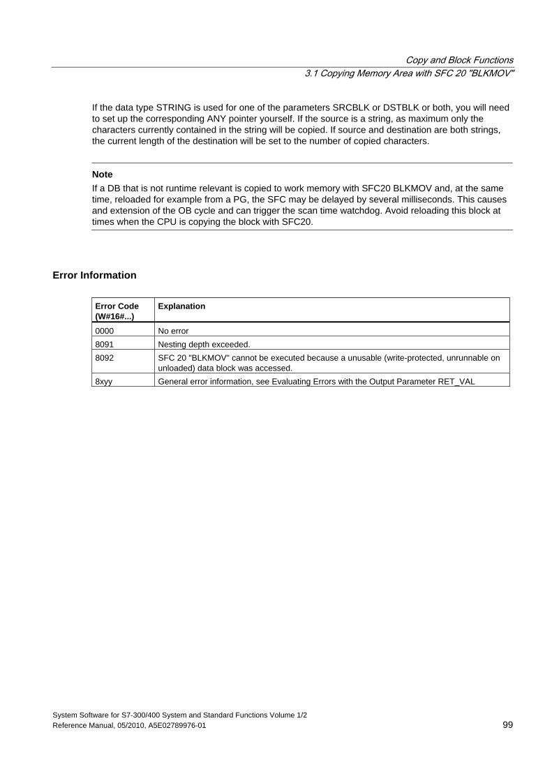
Copy and Block Functions 3.1 Copying Memory Area with SFC 20 "BLKMOV"
System Software for S7-300/400 System and Standard Functions Volume 1/2 Reference Manual, 05/2010, A5E02789976-01 99
If the data type STRING is used for one of the parameters SRCBLK or DSTBLK or both, you will need to set up the corresponding ANY pointer yourself. If the source is a string, as maximum only the characters currently contained in the string will be copied. If source and destination are both strings, the current length of the destination will be set to the number of copied characters.
Note
If a DB that is not runtime relevant is copied to work memory with SFC20 BLKMOV and, at the same time, reloaded for example from a PG, the SFC may be delayed by several milliseconds. This causes and extension of the OB cycle and can trigger the scan time watchdog. Avoid reloading this block at times when the CPU is copying the block with SFC20.
Error Information Error Code (W#16#...)
Explanation
0000 No error 8091 Nesting depth exceeded. 8092 SFC 20 "BLKMOV" cannot be executed because a unusable (write-protected, unrunnable on
unloaded) data block was accessed. 8xyy General error information, see Evaluating Errors with the Output Parameter RET_VAL
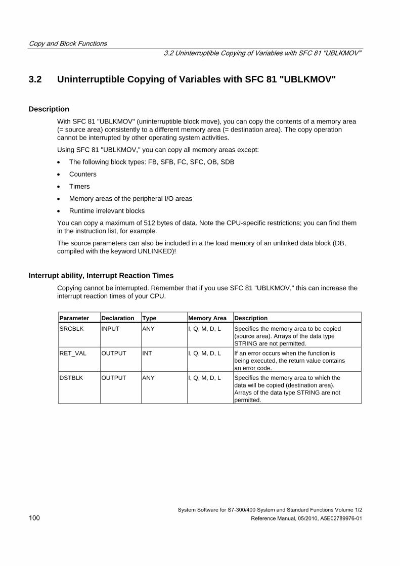
Copy and Block Functions 3.2 Uninterruptible Copying of Variables with SFC 81 "UBLKMOV"
System Software for S7-300/400 System and Standard Functions Volume 1/2 100 Reference Manual, 05/2010, A5E02789976-01
3.2 Uninterruptible Copying of Variables with SFC 81 "UBLKMOV"
Description With SFC 81 "UBLKMOV" (uninterruptible block move), you can copy the contents of a memory area (= source area) consistently to a different memory area (= destination area). The copy operation cannot be interrupted by other operating system activities.
Using SFC 81 "UBLKMOV," you can copy all memory areas except:
• The following block types: FB, SFB, FC, SFC, OB, SDB
• Counters
• Timers
• Memory areas of the peripheral I/O areas
• Runtime irrelevant blocks
You can copy a maximum of 512 bytes of data. Note the CPU-specific restrictions; you can find them in the instruction list, for example.
The source parameters can also be included in a the load memory of an unlinked data block (DB, compiled with the keyword UNLINKED)!
Interrupt ability, Interrupt Reaction Times Copying cannot be interrupted. Remember that if you use SFC 81 "UBLKMOV," this can increase the interrupt reaction times of your CPU.
Parameter Declaration Type Memory Area Description
SRCBLK INPUT ANY I, Q, M, D, L Specifies the memory area to be copied (source area). Arrays of the data type STRING are not permitted.
RET_VAL OUTPUT INT I, Q, M, D, L If an error occurs when the function is being executed, the return value contains an error code.
DSTBLK OUTPUT ANY I, Q, M, D, L Specifies the memory area to which the data will be copied (destination area). Arrays of the data type STRING are not permitted.
Copy and Block Functions 3.2 Uninterruptible Copying of Variables with SFC 81 "UBLKMOV"
System Software for S7-300/400 System and Standard Functions Volume 1/2 Reference Manual, 05/2010, A5E02789976-01 101
Conditions for Source and Destination Field The source and destination field must not overlap. If the specified destination area is larger than the source area, only the amount of data actually in the source area is copied to the destination area.
If the specified destination area is smaller than the source area, only as much data as the destination area can take will be copied.
If the real existing destination or source field is smaller than the size of the memory area for source or destination field as set in the parameters (SRCBLK, DSTBLK), the behavior depends on the CPU type:
• S7-300 CPUs: No data is transferred. RET_VAL has the value W#16#837F.
• The following applies to the S7-400 V4 CPUs (standard CPUs V4, H-CPUs V4 and V4.5): No data is transferred. The following applies to all other S7-400 CPUs: Data is transferred. With all S7-400 CPUs, an error is shown in RET_VAL with the error code W#16#8122 or W#16#8323. Make sure that you always evaluate these RET_VALs in your user program.
If the ANY pointer (source or destination) is of the type BOOL, the specified length must be divisible by 8 otherwise the SFC will not execute.
If the ANY pointer is of the type STRING, the specified length must be 1.
Error Information Error Code (W#16#...) Description
0000 No error 8091 The source area is in an unlinked data block. 8xyy General error information, see Evaluating Errors with the Output
Parameter RET_VAL
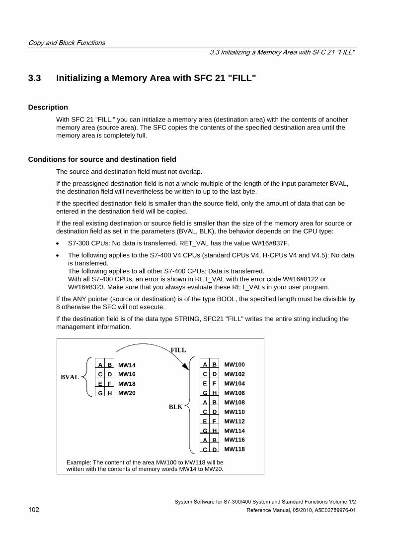
Copy and Block Functions 3.3 Initializing a Memory Area with SFC 21 "FILL"
System Software for S7-300/400 System and Standard Functions Volume 1/2 102 Reference Manual, 05/2010, A5E02789976-01
3.3 Initializing a Memory Area with SFC 21 "FILL"
Description With SFC 21 "FILL," you can initialize a memory area (destination area) with the contents of another memory area (source area). The SFC copies the contents of the specified destination area until the memory area is completely full.
Conditions for source and destination field The source and destination field must not overlap.
If the preassigned destination field is not a whole multiple of the length of the input parameter BVAL, the destination field will nevertheless be written to up to the last byte.
If the specified destination field is smaller than the source field, only the amount of data that can be entered in the destination field will be copied.
If the real existing destination or source field is smaller than the size of the memory area for source or destination field as set in the parameters (BVAL, BLK), the behavior depends on the CPU type:
• S7-300 CPUs: No data is transferred. RET_VAL has the value W#16#837F.
• The following applies to the S7-400 V4 CPUs (standard CPUs V4, H-CPUs V4 and V4.5): No data is transferred. The following applies to all other S7-400 CPUs: Data is transferred. With all S7-400 CPUs, an error is shown in RET_VAL with the error code W#16#8122 or W#16#8323. Make sure that you always evaluate these RET_VALs in your user program.
If the ANY pointer (source or destination) is of the type BOOL, the specified length must be divisible by 8 otherwise the SFC will not execute.
If the destination field is of the data type STRING, SFC21 "FILL" writes the entire string including the management information.
A BC DE FG H
A BC DE FG HA BC DE FG HA BC D
MW14MW16MW18MW20
MW100MW102MW104MW106MW108MW110MW112MW114MW116MW118
BVAL
BLK
FILL
Example: The content of the area MW100 to MW118 will bewritten with the contents of memory words MW14 to MW20.
Copy and Block Functions 3.3 Initializing a Memory Area with SFC 21 "FILL"
System Software for S7-300/400 System and Standard Functions Volume 1/2 Reference Manual, 05/2010, A5E02789976-01 103
Consistency of the Source Data and Target Data Note that the source data remains unchanged while SFC21 "FILL" executes. Otherwise the consistency of the target data cannot be guaranteed.
Exceptions The following cannot be used as the source field:
• Counters
• Timers
You cannot write values to the following using SFC 21:
• The following block types: FB, SFB, FC, SFC, SDB,
• Counters,
• Timers,
• Memory areas of the peripheral I/O area.
Parameter Declaration Data Type Memory Area Description
BVAL INPUT ANY I, Q, M, D, L The parameter BVAL contains the value or description of the area whose contents will be used to initialize the destination area (source area). Arrays of the data type STRING are not permitted.
RET_VAL OUTPUT INT I, Q, M, D, L If an error occurs while the function is being processed, the return value contains an error code.
BLK OUTPUT ANY I, Q, M, D, L The parameter BLK contains the description of the area to be initialized (destination area). Arrays of the data type STRING are not permitted.
Copy and Block Functions 3.3 Initializing a Memory Area with SFC 21 "FILL"
System Software for S7-300/400 System and Standard Functions Volume 1/2 104 Reference Manual, 05/2010, A5E02789976-01
The Input Parameter is a Structure If you transfer a structure as the input parameter, remember the following point:
STEP 7 always defines the length of a structure as an even number of bytes. As a result, the structure will need one byte of additional memory space if you declare a structure with an odd number of bytes.
Example
The structure was declared as:
TYP_5_BYTE_STRUCTURE : STRUCT
BYTE_1_2 : WORD
BYTE_3_4 : WORD
BYTE_5 : BYTE
END_STRUCT
The declared structure "TYP_5_BYTE_STRUCTURE" requires 6 bytes of memory.
Error Information SFC 21 "FILL" only provides general (not specific) error information. See Evaluating Errors with the Output Parameter RET_VAL.
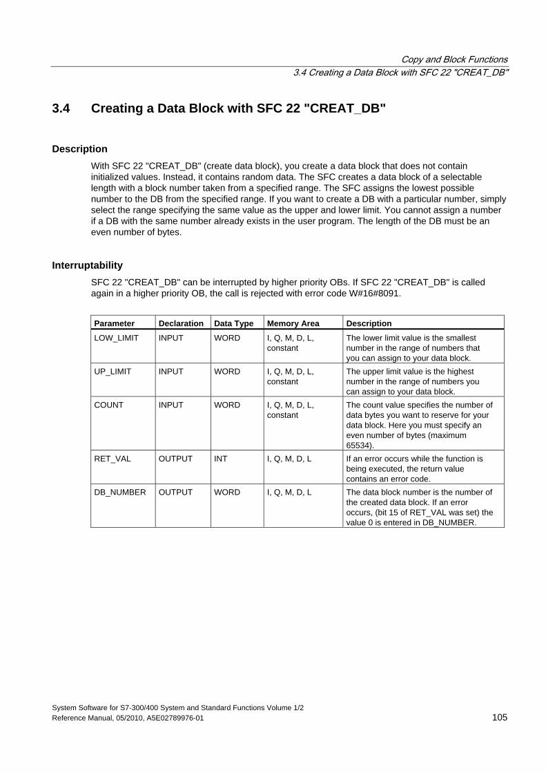
Copy and Block Functions 3.4 Creating a Data Block with SFC 22 "CREAT_DB"
System Software for S7-300/400 System and Standard Functions Volume 1/2 Reference Manual, 05/2010, A5E02789976-01 105
3.4 Creating a Data Block with SFC 22 "CREAT_DB"
Description With SFC 22 "CREAT_DB" (create data block), you create a data block that does not contain initialized values. Instead, it contains random data. The SFC creates a data block of a selectable length with a block number taken from a specified range. The SFC assigns the lowest possible number to the DB from the specified range. If you want to create a DB with a particular number, simply select the range specifying the same value as the upper and lower limit. You cannot assign a number if a DB with the same number already exists in the user program. The length of the DB must be an even number of bytes.
Interruptability SFC 22 "CREAT_DB" can be interrupted by higher priority OBs. If SFC 22 "CREAT_DB" is called again in a higher priority OB, the call is rejected with error code W#16#8091.
Parameter Declaration Data Type Memory Area Description
LOW_LIMIT INPUT WORD I, Q, M, D, L, constant
The lower limit value is the smallest number in the range of numbers that you can assign to your data block.
UP_LIMIT INPUT WORD I, Q, M, D, L, constant
The upper limit value is the highest number in the range of numbers you can assign to your data block.
COUNT INPUT WORD I, Q, M, D, L, constant
The count value specifies the number of data bytes you want to reserve for your data block. Here you must specify an even number of bytes (maximum 65534).
RET_VAL OUTPUT INT I, Q, M, D, L If an error occurs while the function is being executed, the return value contains an error code.
DB_NUMBER OUTPUT WORD I, Q, M, D, L The data block number is the number of the created data block. If an error occurs, (bit 15 of RET_VAL was set) the value 0 is entered in DB_NUMBER.
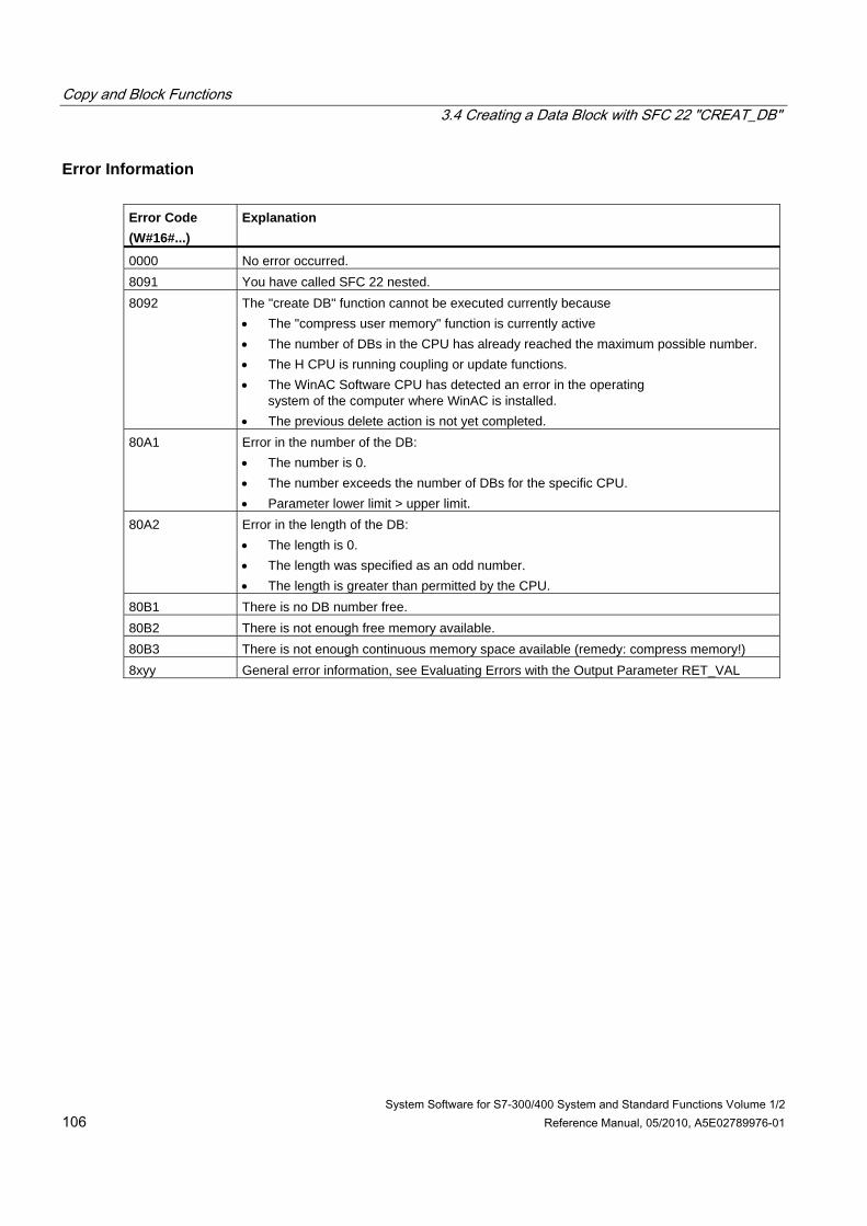
Copy and Block Functions 3.4 Creating a Data Block with SFC 22 "CREAT_DB"
System Software for S7-300/400 System and Standard Functions Volume 1/2 106 Reference Manual, 05/2010, A5E02789976-01
Error Information Error Code (W#16#...)
Explanation
0000 No error occurred. 8091 You have called SFC 22 nested. 8092 The "create DB" function cannot be executed currently because
• The "compress user memory" function is currently active • The number of DBs in the CPU has already reached the maximum possible number. • The H CPU is running coupling or update functions. • The WinAC Software CPU has detected an error in the operating
system of the computer where WinAC is installed. • The previous delete action is not yet completed.
80A1 Error in the number of the DB: • The number is 0. • The number exceeds the number of DBs for the specific CPU. • Parameter lower limit > upper limit.
80A2 Error in the length of the DB: • The length is 0. • The length was specified as an odd number. • The length is greater than permitted by the CPU.
80B1 There is no DB number free. 80B2 There is not enough free memory available. 80B3 There is not enough continuous memory space available (remedy: compress memory!) 8xyy General error information, see Evaluating Errors with the Output Parameter RET_VAL
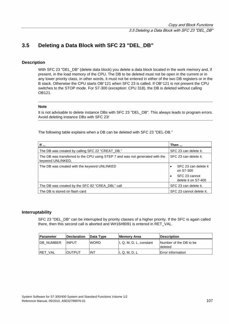
Copy and Block Functions 3.5 Deleting a Data Block with SFC 23 "DEL_DB"
System Software for S7-300/400 System and Standard Functions Volume 1/2 Reference Manual, 05/2010, A5E02789976-01 107
3.5 Deleting a Data Block with SFC 23 "DEL_DB"
Description With SFC 23 "DEL_DB" (delete data block) you delete a data block located in the work memory and, if present, in the load memory of the CPU. The DB to be deleted must not be open in the current or in any lower priority class, in other words, it must not be entered in either of the two DB registers or in the B stack. Otherwise the CPU starts OB°121 when SFC 23 is called. If OB°121 is not present the CPU switches to the STOP mode. For S7-300 (exception: CPU 318), the DB is deleted without calling OB121.
Note
It is not advisable to delete instance DBs with SFC 23 "DEL_DB". This always leads to program errors. Avoid deleting instance DBs with SFC 23!
The following table explains when a DB can be deleted with SFC 23 "DEL-DB."
If ... Then ...
The DB was created by calling SFC 22 "CREAT_DB," SFC 23 can delete it. The DB was transferred to the CPU using STEP 7 and was not generated with the keyword UNLINKED,
SFC 23 can delete it.
The DB was created with the keyword UNLINKED • SFC 23 can delete it on S7-300
• SFC 23 cannot delete it on S7-400
The DB was created by the SFC 82 "CREA_DBL" call SFC 23 can delete it. The DB is stored on flash card SFC 23 cannot delete it.
Interruptability SFC 23 "DEL_DB" can be interrupted by priority classes of a higher priority. If the SFC is again called there, then this second call is aborted and W#16#8091 is entered in RET_VAL.
Parameter Declaration Data Type Memory Area Description
DB_NUMBER INPUT WORD I, Q, M, D, L, constant Number of the DB to be deleted
RET_VAL OUTPUT INT I, Q, M, D, L Error information
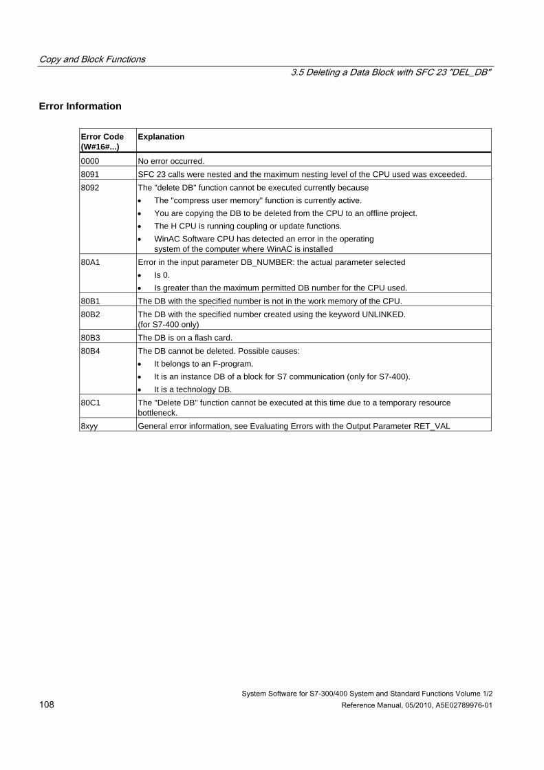
Copy and Block Functions 3.5 Deleting a Data Block with SFC 23 "DEL_DB"
System Software for S7-300/400 System and Standard Functions Volume 1/2 108 Reference Manual, 05/2010, A5E02789976-01
Error Information Error Code (W#16#...)
Explanation
0000 No error occurred. 8091 SFC 23 calls were nested and the maximum nesting level of the CPU used was exceeded. 8092 The "delete DB" function cannot be executed currently because
• The "compress user memory" function is currently active. • You are copying the DB to be deleted from the CPU to an offline project. • The H CPU is running coupling or update functions. • WinAC Software CPU has detected an error in the operating
system of the computer where WinAC is installed 80A1 Error in the input parameter DB_NUMBER: the actual parameter selected
• Is 0. • Is greater than the maximum permitted DB number for the CPU used.
80B1 The DB with the specified number is not in the work memory of the CPU. 80B2 The DB with the specified number created using the keyword UNLINKED.
(for S7-400 only) 80B3 The DB is on a flash card. 80B4 The DB cannot be deleted. Possible causes:
• It belongs to an F-program. • It is an instance DB of a block for S7 communication (only for S7-400). • It is a technology DB.
80C1 The "Delete DB" function cannot be executed at this time due to a temporary resource bottleneck.
8xyy General error information, see Evaluating Errors with the Output Parameter RET_VAL
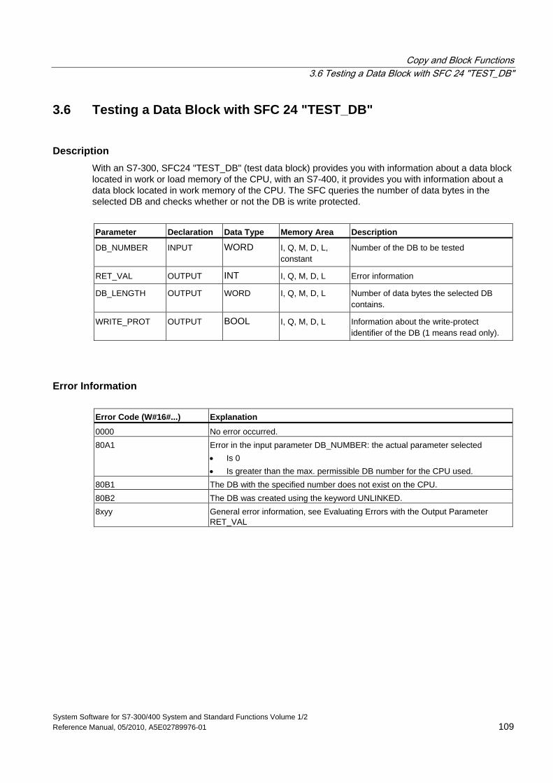
Copy and Block Functions 3.6 Testing a Data Block with SFC 24 "TEST_DB"
System Software for S7-300/400 System and Standard Functions Volume 1/2 Reference Manual, 05/2010, A5E02789976-01 109
3.6 Testing a Data Block with SFC 24 "TEST_DB"
Description With an S7-300, SFC24 "TEST_DB" (test data block) provides you with information about a data block located in work or load memory of the CPU, with an S7-400, it provides you with information about a data block located in work memory of the CPU. The SFC queries the number of data bytes in the selected DB and checks whether or not the DB is write protected.
Parameter Declaration Data Type Memory Area Description
DB_NUMBER INPUT WORD I, Q, M, D, L, constant
Number of the DB to be tested
RET_VAL OUTPUT INT I, Q, M, D, L Error information
DB_LENGTH OUTPUT WORD I, Q, M, D, L Number of data bytes the selected DB contains.
WRITE_PROT OUTPUT BOOL I, Q, M, D, L Information about the write-protect identifier of the DB (1 means read only).
Error Information Error Code (W#16#...) Explanation
0000 No error occurred. 80A1 Error in the input parameter DB_NUMBER: the actual parameter selected
• Is 0 • Is greater than the max. permissible DB number for the CPU used.
80B1 The DB with the specified number does not exist on the CPU. 80B2 The DB was created using the keyword UNLINKED. 8xyy General error information, see Evaluating Errors with the Output Parameter
RET_VAL
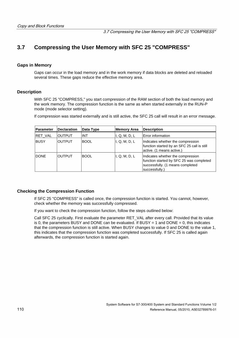
Copy and Block Functions 3.7 Compressing the User Memory with SFC 25 "COMPRESS"
System Software for S7-300/400 System and Standard Functions Volume 1/2 110 Reference Manual, 05/2010, A5E02789976-01
3.7 Compressing the User Memory with SFC 25 "COMPRESS"
Gaps in Memory Gaps can occur in the load memory and in the work memory if data blocks are deleted and reloaded several times. These gaps reduce the effective memory area.
Description With SFC 25 "COMPRESS," you start compression of the RAM section of both the load memory and the work memory. The compression function is the same as when started externally in the RUN-P mode (mode selector setting).
If compression was started externally and is still active, the SFC 25 call will result in an error message.
Parameter Declaration Data Type Memory Area Description
RET_VAL OUTPUT INT I, Q, M, D, L Error information BUSY OUTPUT BOOL I, Q, M, D, L Indicates whether the compression
function started by an SFC 25 call is still active. (1 means active.)
DONE OUTPUT BOOL I, Q, M, D, L Indicates whether the compression function started by SFC 25 was completed successfully. (1 means completed successfully.)
Checking the Compression Function If SFC 25 "COMPRESS" is called once, the compression function is started. You cannot, however, check whether the memory was successfully compressed.
If you want to check the compression function, follow the steps outlined below:
Call SFC 25 cyclically. First evaluate the parameter RET_VAL after every call. Provided that its value is 0, the parameters BUSY and DONE can be evaluated. If BUSY = 1 and DONE = 0, this indicates that the compression function is still active. When BUSY changes to value 0 and DONE to the value 1, this indicates that the compression function was completed successfully. If SFC 25 is called again afterwards, the compression function is started again.
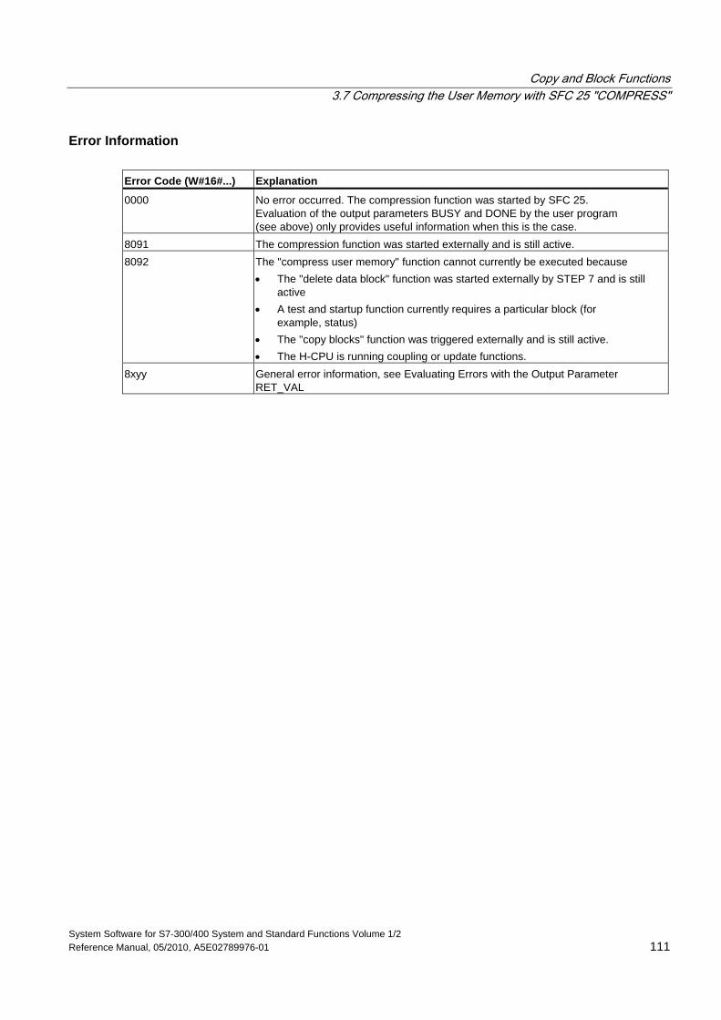
Copy and Block Functions 3.7 Compressing the User Memory with SFC 25 "COMPRESS"
System Software for S7-300/400 System and Standard Functions Volume 1/2 Reference Manual, 05/2010, A5E02789976-01 111
Error Information Error Code (W#16#...) Explanation
0000 No error occurred. The compression function was started by SFC 25. Evaluation of the output parameters BUSY and DONE by the user program (see above) only provides useful information when this is the case.
8091 The compression function was started externally and is still active. 8092 The "compress user memory" function cannot currently be executed because
• The "delete data block" function was started externally by STEP 7 and is still active
• A test and startup function currently requires a particular block (for example, status)
• The "copy blocks" function was triggered externally and is still active. • The H-CPU is running coupling or update functions.
8xyy General error information, see Evaluating Errors with the Output Parameter RET_VAL
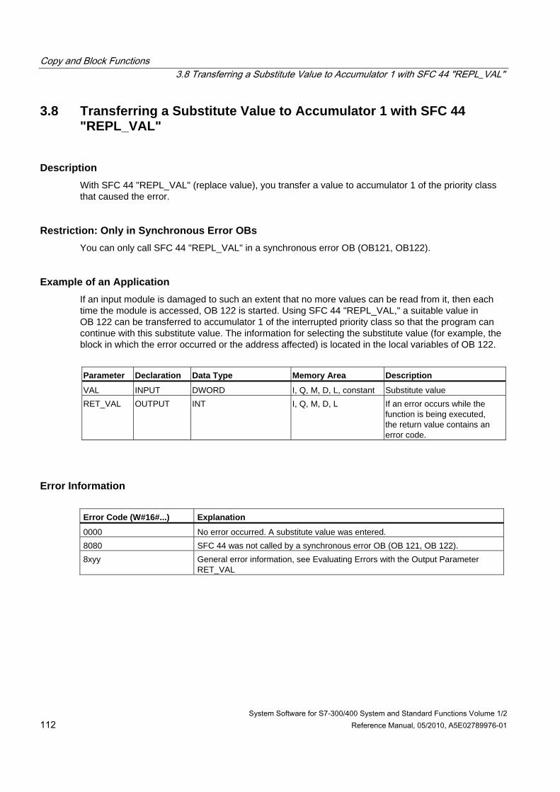
Copy and Block Functions 3.8 Transferring a Substitute Value to Accumulator 1 with SFC 44 "REPL_VAL"
System Software for S7-300/400 System and Standard Functions Volume 1/2 112 Reference Manual, 05/2010, A5E02789976-01
3.8 Transferring a Substitute Value to Accumulator 1 with SFC 44 "REPL_VAL"
Description With SFC 44 "REPL_VAL" (replace value), you transfer a value to accumulator 1 of the priority class that caused the error.
Restriction: Only in Synchronous Error OBs You can only call SFC 44 "REPL_VAL" in a synchronous error OB (OB121, OB122).
Example of an Application If an input module is damaged to such an extent that no more values can be read from it, then each time the module is accessed, OB 122 is started. Using SFC 44 "REPL_VAL," a suitable value in OB 122 can be transferred to accumulator 1 of the interrupted priority class so that the program can continue with this substitute value. The information for selecting the substitute value (for example, the block in which the error occurred or the address affected) is located in the local variables of OB 122.
Parameter Declaration Data Type Memory Area Description
VAL INPUT DWORD I, Q, M, D, L, constant Substitute value RET_VAL OUTPUT INT I, Q, M, D, L If an error occurs while the
function is being executed, the return value contains an error code.
Error Information Error Code (W#16#...) Explanation
0000 No error occurred. A substitute value was entered. 8080 SFC 44 was not called by a synchronous error OB (OB 121, OB 122). 8xyy General error information, see Evaluating Errors with the Output Parameter
RET_VAL
Copy and Block Functions 3.9 Generating Data Blocks in Load Memory with SFC 82 "CREA_DBL"
System Software for S7-300/400 System and Standard Functions Volume 1/2 Reference Manual, 05/2010, A5E02789976-01 113
3.9 Generating Data Blocks in Load Memory with SFC 82 "CREA_DBL"
Description With SFC 82 "CREA_DBL" (create data block in load memory) you can create a new data block in the load memory (Micro Memory Card). The SFC 82 generates a default size data block using a number from a specified range and. The SFC 82 assigns the smallest possible number to the DB. You can generate a DB with a certain number by assigning the same number to the upper and to the lower limit of the rage to be specified. You cannot assign numbers that are already assigned to DBs that exist in the user program. If a DB already exists with the same number in work memory and/or load memory or if the DB exists as copied version the SFC is terminated and an error message is generated.
Note
With the SFC 24 "TEST_DB" you can determine whether a DB with the same number already exists.
The content of the data area to which the parameter SRCBLK (source block) points are written to the DB. This data area must be a DB or an area from a DB. To maintain consistency, you must not change this data area while the SFC 82 is being processed (i.e. as long as the BUSY parameter has the value TRUE).
A DB with READ_ONLY attribute can only be created and initialized by SFC 82.
The SFC 82 does not change the checksum of the user program.
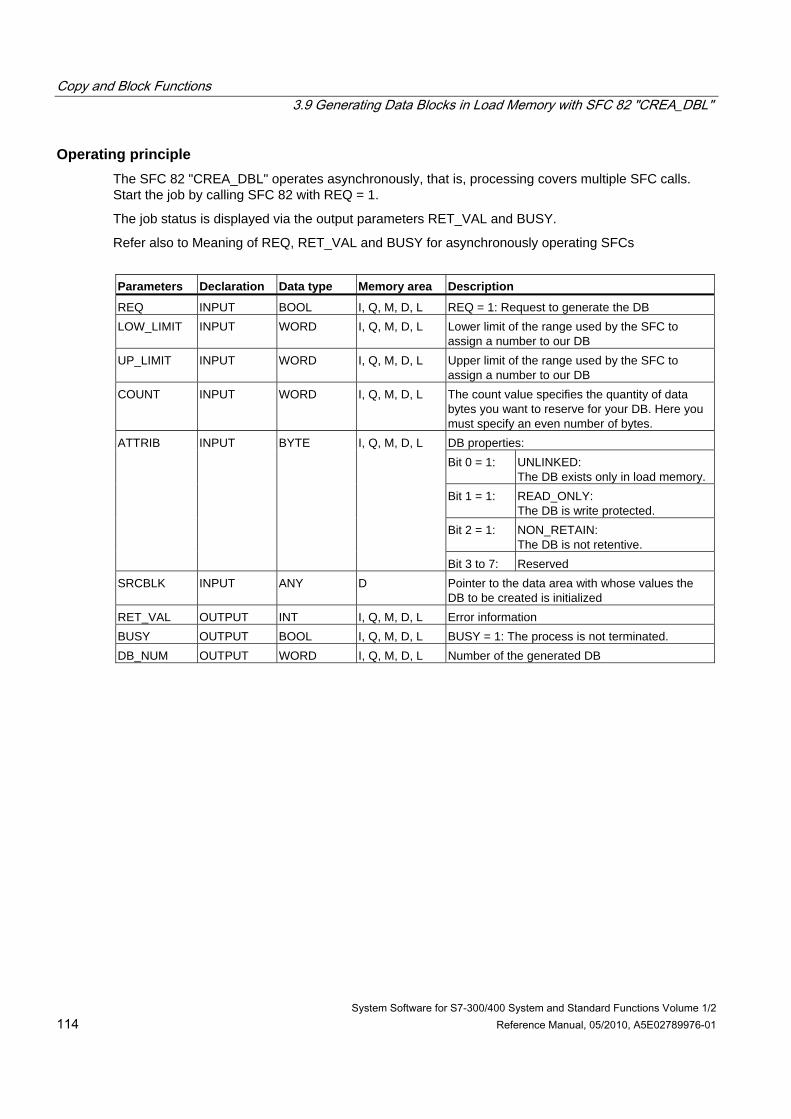
Copy and Block Functions 3.9 Generating Data Blocks in Load Memory with SFC 82 "CREA_DBL"
System Software for S7-300/400 System and Standard Functions Volume 1/2 114 Reference Manual, 05/2010, A5E02789976-01
Operating principle The SFC 82 "CREA_DBL" operates asynchronously, that is, processing covers multiple SFC calls. Start the job by calling SFC 82 with REQ = 1.
The job status is displayed via the output parameters RET_VAL and BUSY.
Refer also to Meaning of REQ, RET_VAL and BUSY for asynchronously operating SFCs
Parameters Declaration Data type Memory area Description
REQ INPUT BOOL I, Q, M, D, L REQ = 1: Request to generate the DB LOW_LIMIT INPUT WORD I, Q, M, D, L Lower limit of the range used by the SFC to
assign a number to our DB UP_LIMIT INPUT WORD I, Q, M, D, L Upper limit of the range used by the SFC to
assign a number to our DB COUNT INPUT WORD I, Q, M, D, L The count value specifies the quantity of data
bytes you want to reserve for your DB. Here you must specify an even number of bytes. DB properties: Bit 0 = 1: UNLINKED:
The DB exists only in load memory. Bit 1 = 1: READ_ONLY:
The DB is write protected. Bit 2 = 1: NON_RETAIN:
The DB is not retentive.
ATTRIB INPUT BYTE I, Q, M, D, L
Bit 3 to 7: Reserved SRCBLK INPUT ANY D Pointer to the data area with whose values the
DB to be created is initialized RET_VAL OUTPUT INT I, Q, M, D, L Error information BUSY OUTPUT BOOL I, Q, M, D, L BUSY = 1: The process is not terminated. DB_NUM OUTPUT WORD I, Q, M, D, L Number of the generated DB
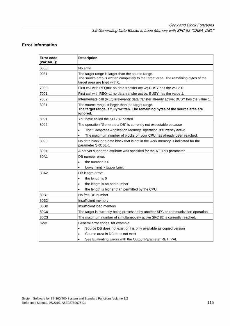
Copy and Block Functions 3.9 Generating Data Blocks in Load Memory with SFC 82 "CREA_DBL"
System Software for S7-300/400 System and Standard Functions Volume 1/2 Reference Manual, 05/2010, A5E02789976-01 115
Error Information Error code (W#16#...):
Description
0000 No error 0081 The target range is larger than the source range.
The source area is written completely to the target area. The remaining bytes of the target area are filled with 0.
7000 First call with REQ=0: no data transfer active; BUSY has the value 0. 7001 First call with REQ=1: no data transfer active; BUSY has the value 1. 7002 Intermediate call (REQ irrelevant): data transfer already active; BUSY has the value 1. 8081 The source range is larger than the target range.
The target range is fully written. The remaining bytes of the source area are ignored.
8091 You have called the SFC 82 nested. 8092 The operation "Generate a DB" is currently not executable because
• The "Compress Application Memory" operation is currently active • The maximum number of blocks on your CPU has already been reached.
8093 No data block or a data block that is not in the work memory is indicated for the parameter SRCBLK.
8094 A not yet supported attribute was specified for the ATTRIB parameter 80A1 DB number error:
• the number is 0 • Lower limit > Upper Limit
80A2 DB length error: • the length is 0 • the length is an odd number • the length is higher than permitted by the CPU
80B1 No free DB number 80B2 Insufficient memory 80BB Insufficient load memory 80C0 The target is currently being processed by another SFC or communication operation. 80C3 The maximum number of simultaneously active SFC 82 is currently reached. 8xyy General error codes, for example:
• Source DB does not exist or it is only available as copied version • Source area in DB does not exist • See Evaluating Errors with the Output Parameter RET_VAL
Copy and Block Functions 3.10 Reading from a Data Block In Load Memory with SFC 83 "READ_DBL"
System Software for S7-300/400 System and Standard Functions Volume 1/2 116 Reference Manual, 05/2010, A5E02789976-01
3.10 Reading from a Data Block In Load Memory with SFC 83 "READ_DBL"
Description Use SFC 83 "READ_DBL" (read data block in load memory) to copy a DB or an area from a DB in load memory (Micro Memory Card) to the data area of a target DB. The target DB must be relevant for execution; that is, it must not be created with the attribute UNLINKED. The content of the load memory is not changed during the copy process.
To ensure consistency, you must not change the target area while the SFC83 is being processed (i.e. as long as the BUSY parameter has the value TRUE).
The following restrictions apply to the parameters SRCBLK (source block) and DSTBLK (destination block):
• For an ANY pointer of the type BOOLEAN the length must be divisible by 8.
• For an ANY pointer of the type BOOLEAN the length must be divisible by 1.
If required, you can determine the length of the source area with SFC 24 "TEST_DB".
Note
The SFC 83 is processed asynchronously. Therefore, it is not suitable for frequent (or cyclical) reading of variables from load memory.
Note
Once started, a job is always completed. If the maximum number of simultaneously active SFC 83 is reached and you call SFC 83 once again at this time in a priority class having higher priority, error code W#16#80C3 will be returned. As such, it does not make sense to restart the high-priority job right away.
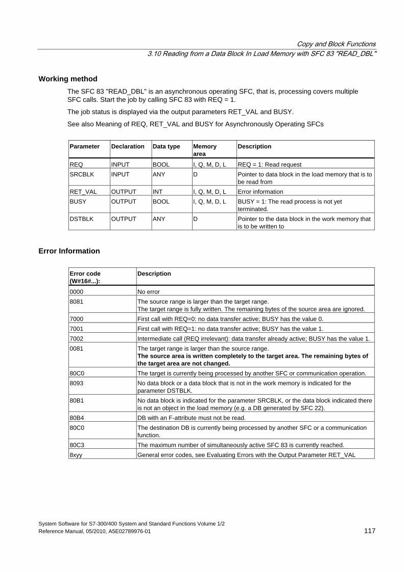
Copy and Block Functions 3.10 Reading from a Data Block In Load Memory with SFC 83 "READ_DBL"
System Software for S7-300/400 System and Standard Functions Volume 1/2 Reference Manual, 05/2010, A5E02789976-01 117
Working method The SFC 83 "READ_DBL" is an asynchronous operating SFC, that is, processing covers multiple SFC calls. Start the job by calling SFC 83 with REQ = 1.
The job status is displayed via the output parameters RET_VAL and BUSY.
See also Meaning of REQ, RET_VAL and BUSY for Asynchronously Operating SFCs
Parameter Declaration Data type Memory
area Description
REQ INPUT BOOL I, Q, M, D, L REQ = 1: Read request SRCBLK INPUT ANY D Pointer to data block in the load memory that is to
be read from RET_VAL OUTPUT INT I, Q, M, D, L Error information BUSY OUTPUT BOOL I, Q, M, D, L BUSY = 1: The read process is not yet
terminated. DSTBLK OUTPUT ANY D Pointer to the data block in the work memory that
is to be written to
Error Information Error code (W#16#...):
Description
0000 No error 8081 The source range is larger than the target range.
The target range is fully written. The remaining bytes of the source area are ignored. 7000 First call with REQ=0: no data transfer active; BUSY has the value 0. 7001 First call with REQ=1: no data transfer active; BUSY has the value 1. 7002 Intermediate call (REQ irrelevant): data transfer already active; BUSY has the value 1. 0081 The target range is larger than the source range.
The source area is written completely to the target area. The remaining bytes of the target area are not changed.
80C0 The target is currently being processed by another SFC or communication operation. 8093 No data block or a data block that is not in the work memory is indicated for the
parameter DSTBLK. 80B1 No data block is indicated for the parameter SRCBLK, or the data block indicated there
is not an object in the load memory (e.g. a DB generated by SFC 22). 80B4 DB with an F-attribute must not be read. 80C0 The destination DB is currently being processed by another SFC or a communication
function. 80C3 The maximum number of simultaneously active SFC 83 is currently reached. 8xyy General error codes, see Evaluating Errors with the Output Parameter RET_VAL
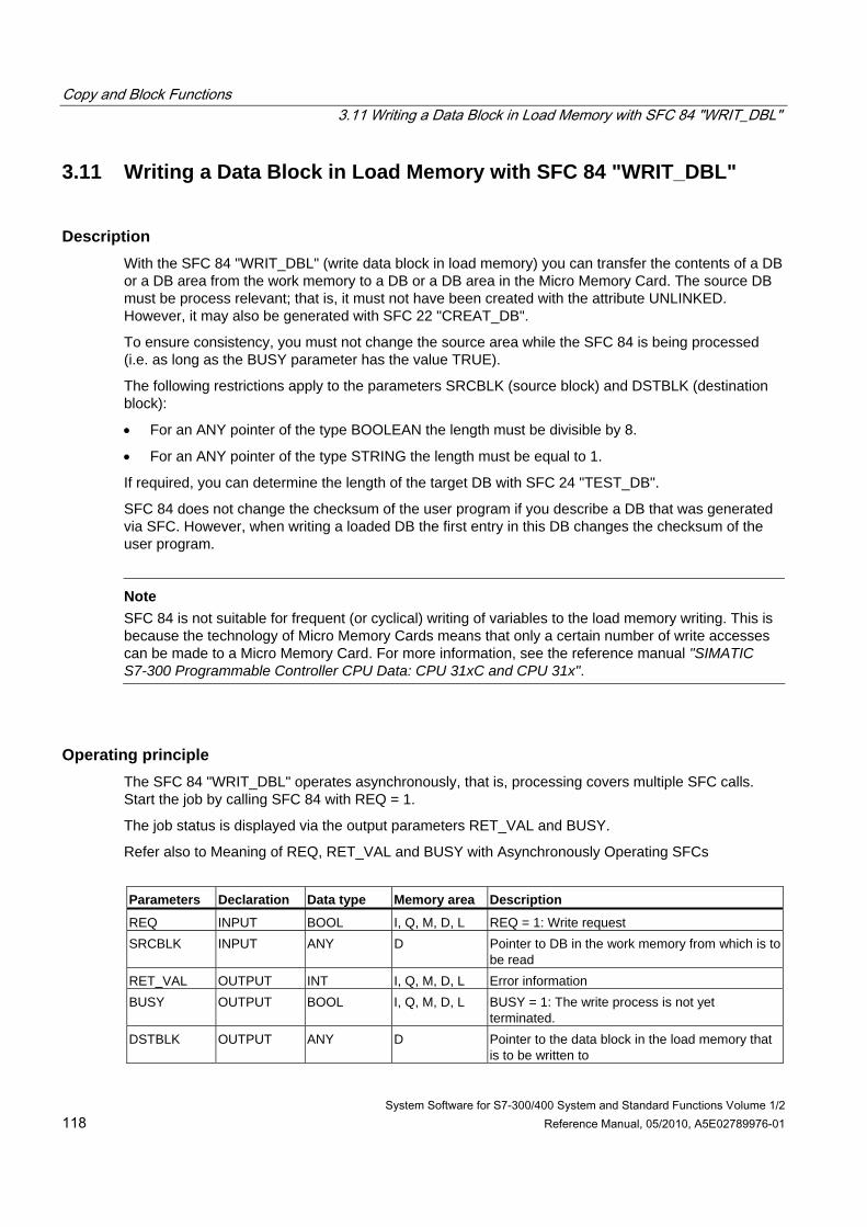
Copy and Block Functions 3.11 Writing a Data Block in Load Memory with SFC 84 "WRIT_DBL"
System Software for S7-300/400 System and Standard Functions Volume 1/2 118 Reference Manual, 05/2010, A5E02789976-01
3.11 Writing a Data Block in Load Memory with SFC 84 "WRIT_DBL"
Description With the SFC 84 "WRIT_DBL" (write data block in load memory) you can transfer the contents of a DB or a DB area from the work memory to a DB or a DB area in the Micro Memory Card. The source DB must be process relevant; that is, it must not have been created with the attribute UNLINKED. However, it may also be generated with SFC 22 "CREAT_DB".
To ensure consistency, you must not change the source area while the SFC 84 is being processed (i.e. as long as the BUSY parameter has the value TRUE).
The following restrictions apply to the parameters SRCBLK (source block) and DSTBLK (destination block):
• For an ANY pointer of the type BOOLEAN the length must be divisible by 8.
• For an ANY pointer of the type STRING the length must be equal to 1.
If required, you can determine the length of the target DB with SFC 24 "TEST_DB".
SFC 84 does not change the checksum of the user program if you describe a DB that was generated via SFC. However, when writing a loaded DB the first entry in this DB changes the checksum of the user program.
Note
SFC 84 is not suitable for frequent (or cyclical) writing of variables to the load memory writing. This is because the technology of Micro Memory Cards means that only a certain number of write accesses can be made to a Micro Memory Card. For more information, see the reference manual "SIMATIC S7-300 Programmable Controller CPU Data: CPU 31xC and CPU 31x".
Operating principle The SFC 84 "WRIT_DBL" operates asynchronously, that is, processing covers multiple SFC calls. Start the job by calling SFC 84 with REQ = 1.
The job status is displayed via the output parameters RET_VAL and BUSY.
Refer also to Meaning of REQ, RET_VAL and BUSY with Asynchronously Operating SFCs
Parameters Declaration Data type Memory area Description
REQ INPUT BOOL I, Q, M, D, L REQ = 1: Write request SRCBLK INPUT ANY D Pointer to DB in the work memory from which is to
be read RET_VAL OUTPUT INT I, Q, M, D, L Error information BUSY OUTPUT BOOL I, Q, M, D, L BUSY = 1: The write process is not yet
terminated. DSTBLK OUTPUT ANY D Pointer to the data block in the load memory that
is to be written to
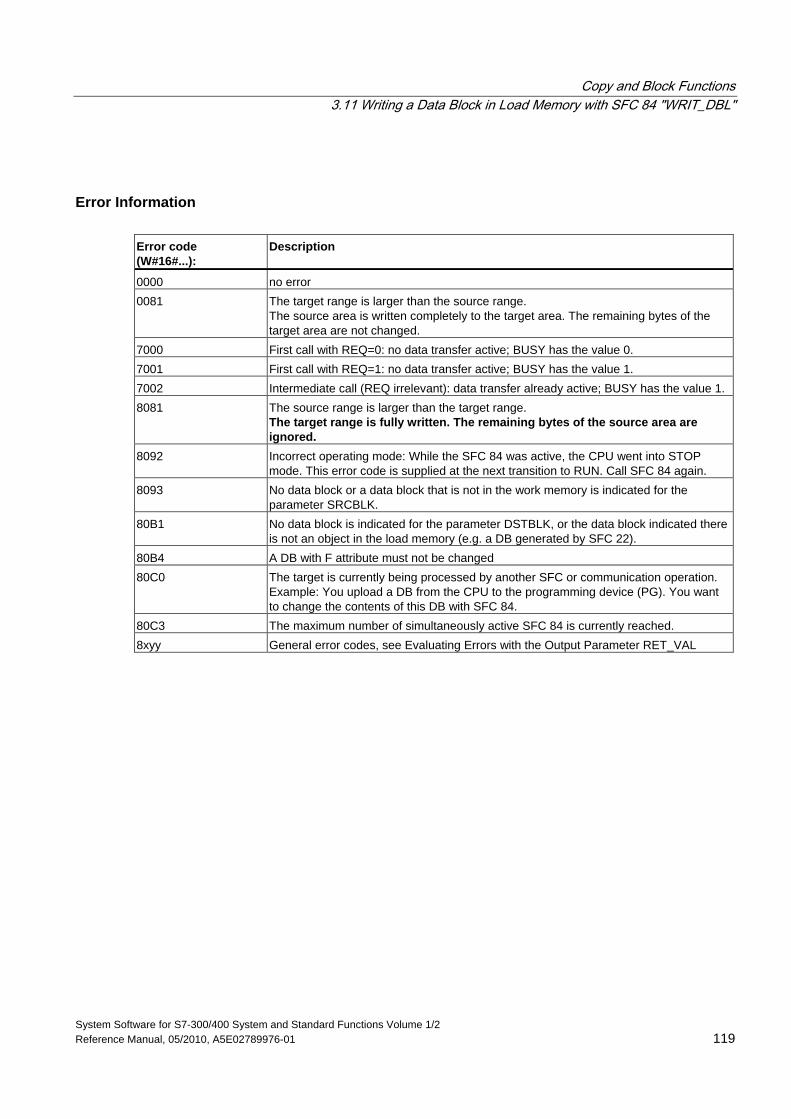
Copy and Block Functions 3.11 Writing a Data Block in Load Memory with SFC 84 "WRIT_DBL"
System Software for S7-300/400 System and Standard Functions Volume 1/2 Reference Manual, 05/2010, A5E02789976-01 119
Error Information Error code (W#16#...):
Description
0000 no error 0081 The target range is larger than the source range.
The source area is written completely to the target area. The remaining bytes of the target area are not changed.
7000 First call with REQ=0: no data transfer active; BUSY has the value 0. 7001 First call with REQ=1: no data transfer active; BUSY has the value 1. 7002 Intermediate call (REQ irrelevant): data transfer already active; BUSY has the value 1. 8081 The source range is larger than the target range.
The target range is fully written. The remaining bytes of the source area are ignored.
8092 Incorrect operating mode: While the SFC 84 was active, the CPU went into STOP mode. This error code is supplied at the next transition to RUN. Call SFC 84 again.
8093 No data block or a data block that is not in the work memory is indicated for the parameter SRCBLK.
80B1 No data block is indicated for the parameter DSTBLK, or the data block indicated there is not an object in the load memory (e.g. a DB generated by SFC 22).
80B4 A DB with F attribute must not be changed 80C0 The target is currently being processed by another SFC or communication operation.
Example: You upload a DB from the CPU to the programming device (PG). You want to change the contents of this DB with SFC 84.
80C3 The maximum number of simultaneously active SFC 84 is currently reached. 8xyy General error codes, see Evaluating Errors with the Output Parameter RET_VAL
Copy and Block Functions 3.12 Creating a Data Block with SFC 85 "CREA_DB"
System Software for S7-300/400 System and Standard Functions Volume 1/2 120 Reference Manual, 05/2010, A5E02789976-01
3.12 Creating a Data Block with SFC 85 "CREA_DB"
Description With SFC 85 "CREA_DB" (create data block) you create a data block with no default values in the user program. Instead, the DB contains random data. The SFC creates a data block with a number from a specified area and with a default size. The SFC assigns the smallest possible number from this area to the DB. To create a DB with a specific number, enter the same number for the upper and lower limits of the default area. You cannot issue the numbers from the DBs already continued in the user program. The length of the DB must be specified with an even number.
Depending on the selection made for the ATTRIB parameter, the DB created has the property RETAIN or NON_RETAIN:
• RETAIN means that the DB is created in the retentive part of the work memory. This means the current values of the DB are retained after each power OFF/power ON transition and every restart (warm restart).
• NON_RETAIN means that the DB is created in the non-retentive part of the work memory. . This means the current values of the DB are undefined after each power OFF/power ON transition and every restart (warm restart).
If no distinction is made between retentive and non-retentive work memory, the ATTRIB parameter is ignored. This means the values of the DB are retained after each power OFF/power ON transition and every restart (warm restart).
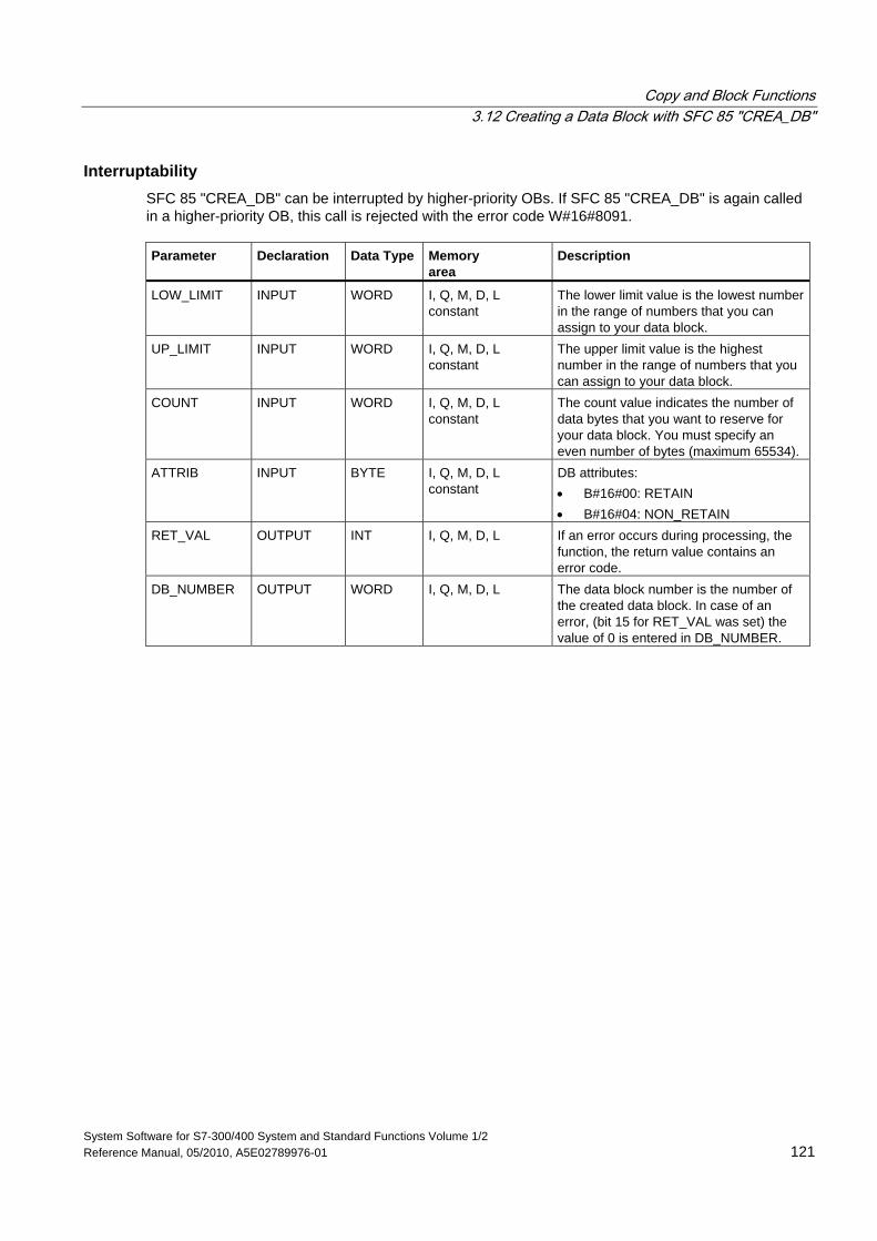
Copy and Block Functions 3.12 Creating a Data Block with SFC 85 "CREA_DB"
System Software for S7-300/400 System and Standard Functions Volume 1/2 Reference Manual, 05/2010, A5E02789976-01 121
Interruptability SFC 85 "CREA_DB" can be interrupted by higher-priority OBs. If SFC 85 "CREA_DB" is again called in a higher-priority OB, this call is rejected with the error code W#16#8091. Parameter Declaration Data Type Memory
area Description
LOW_LIMIT INPUT WORD I, Q, M, D, L constant
The lower limit value is the lowest number in the range of numbers that you can assign to your data block.
UP_LIMIT INPUT WORD I, Q, M, D, L constant
The upper limit value is the highest number in the range of numbers that you can assign to your data block.
COUNT INPUT WORD I, Q, M, D, L constant
The count value indicates the number of data bytes that you want to reserve for your data block. You must specify an even number of bytes (maximum 65534).
ATTRIB INPUT BYTE I, Q, M, D, L constant
DB attributes: • B#16#00: RETAIN • B#16#04: NON_RETAIN
RET_VAL OUTPUT INT I, Q, M, D, L If an error occurs during processing, the function, the return value contains an error code.
DB_NUMBER OUTPUT WORD I, Q, M, D, L The data block number is the number of the created data block. In case of an error, (bit 15 for RET_VAL was set) the value of 0 is entered in DB_NUMBER.
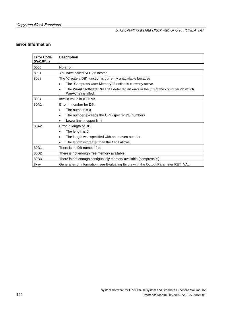
Copy and Block Functions 3.12 Creating a Data Block with SFC 85 "CREA_DB"
System Software for S7-300/400 System and Standard Functions Volume 1/2 122 Reference Manual, 05/2010, A5E02789976-01
Error Information Error Code (W#16#...)
Description
0000 No error 8091 You have called SFC 85 nested. 8092 The "Create a DB" function is currently unavailable because
• The "Compress User Memory" function is currently active • The WinAC software CPU has detected an error in the OS of the computer on which
WinAC is installed. 8094 Invalid value in ATTRIB 80A1 Error in number for DB:
• The number is 0 • The number exceeds the CPU-specific DB numbers • Lower limit > upper limit
80A2 Error in length of DB: • The length is 0 • The length was specified with an uneven number • The length is greater than the CPU allows
80B1 There is no DB number free. 80B2 There is not enough free memory available. 80B3 There is not enough contiguously memory available (compress it!) 8xyy General error information, see Evaluating Errors with the Output Parameter RET_VAL
System Software for S7-300/400 System and Standard Functions Volume 1/2 Reference Manual, 05/2010, A5E02789976-01 123
4 SFCs for Controlling Program Execution
4.1 Re-triggering Cycle Time Monitoring with SFC 43 "RE_TRIGR"
Description With SFC 43 "RE_TRIGR" (re-trigger watchdog), you can re-trigger the cycle time monitoring.
Parameters SFC 43 "RE_TRIGR" has no parameters.
Error Information SFC 43 "RE_TRIGR" does not provide any error information.
4.2 Changing the CPU to STOP with SFC 46 "STP"
Description With SFC 46 "STP" (stop), you change the CPU to the STOP mode.
Parameters SFC 46 "STP" does not have any parameters.
Error Information SFC 46 "STP" does not provide any error information.
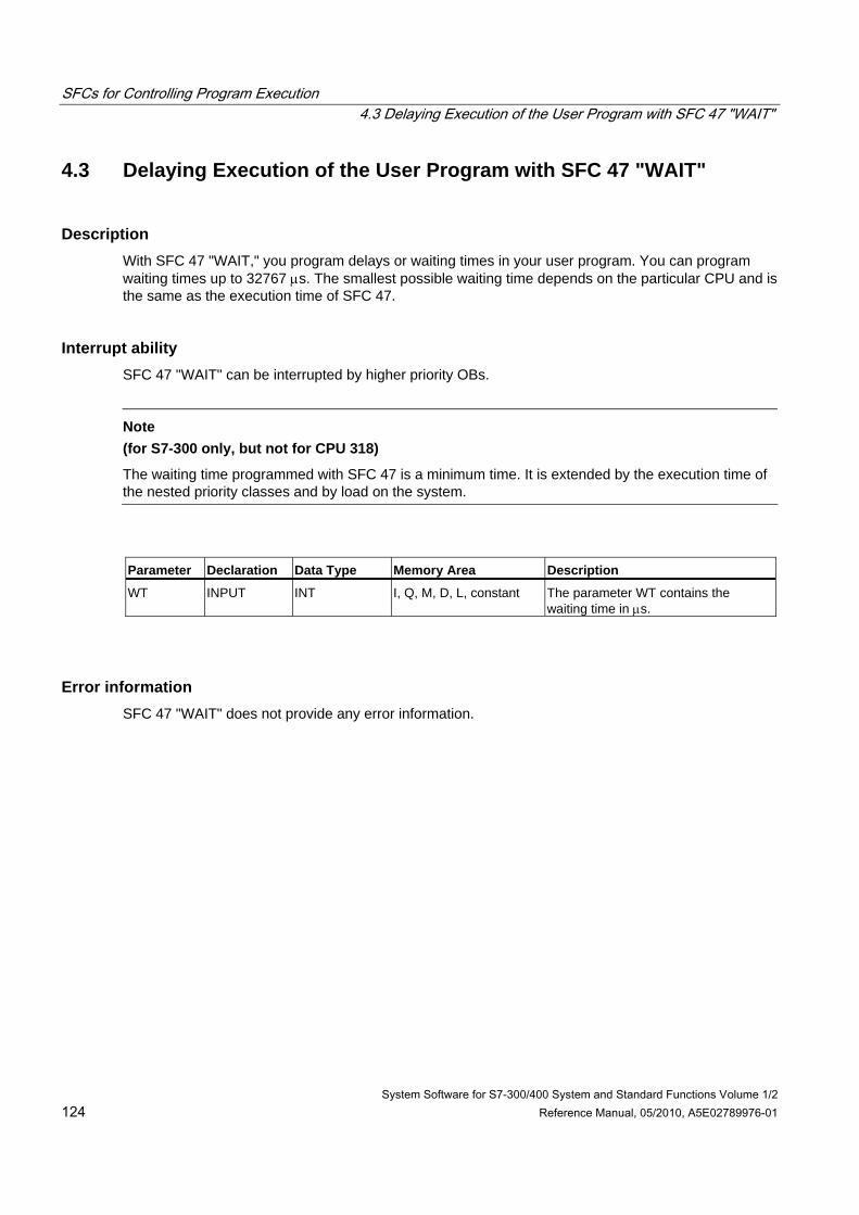
SFCs for Controlling Program Execution 4.3 Delaying Execution of the User Program with SFC 47 "WAIT"
System Software for S7-300/400 System and Standard Functions Volume 1/2 124 Reference Manual, 05/2010, A5E02789976-01
4.3 Delaying Execution of the User Program with SFC 47 "WAIT"
Description With SFC 47 "WAIT," you program delays or waiting times in your user program. You can program waiting times up to 32767 μs. The smallest possible waiting time depends on the particular CPU and is the same as the execution time of SFC 47.
Interrupt ability SFC 47 "WAIT" can be interrupted by higher priority OBs.
Note
(for S7-300 only, but not for CPU 318)
The waiting time programmed with SFC 47 is a minimum time. It is extended by the execution time of the nested priority classes and by load on the system.
Parameter Declaration Data Type Memory Area Description
WT INPUT INT I, Q, M, D, L, constant The parameter WT contains the waiting time in μs.
Error information SFC 47 "WAIT" does not provide any error information.
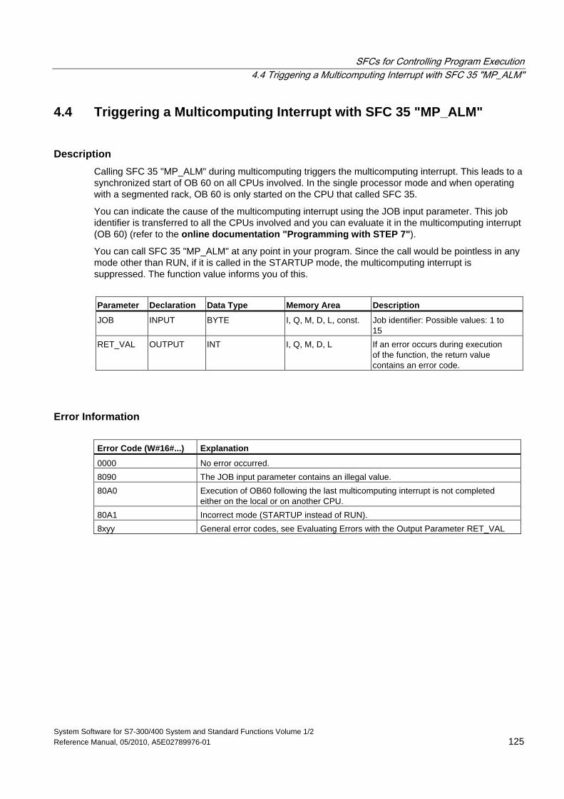
SFCs for Controlling Program Execution 4.4 Triggering a Multicomputing Interrupt with SFC 35 "MP_ALM"
System Software for S7-300/400 System and Standard Functions Volume 1/2 Reference Manual, 05/2010, A5E02789976-01 125
4.4 Triggering a Multicomputing Interrupt with SFC 35 "MP_ALM"
Description Calling SFC 35 "MP_ALM" during multicomputing triggers the multicomputing interrupt. This leads to a synchronized start of OB 60 on all CPUs involved. In the single processor mode and when operating with a segmented rack, OB 60 is only started on the CPU that called SFC 35.
You can indicate the cause of the multicomputing interrupt using the JOB input parameter. This job identifier is transferred to all the CPUs involved and you can evaluate it in the multicomputing interrupt (OB 60) (refer to the online documentation "Programming with STEP 7").
You can call SFC 35 "MP_ALM" at any point in your program. Since the call would be pointless in any mode other than RUN, if it is called in the STARTUP mode, the multicomputing interrupt is suppressed. The function value informs you of this.
Parameter Declaration Data Type Memory Area Description
JOB INPUT BYTE I, Q, M, D, L, const. Job identifier: Possible values: 1 to 15
RET_VAL OUTPUT INT I, Q, M, D, L If an error occurs during execution of the function, the return value contains an error code.
Error Information Error Code (W#16#...) Explanation
0000 No error occurred. 8090 The JOB input parameter contains an illegal value. 80A0 Execution of OB60 following the last multicomputing interrupt is not completed
either on the local or on another CPU. 80A1 Incorrect mode (STARTUP instead of RUN). 8xyy General error codes, see Evaluating Errors with the Output Parameter RET_VAL
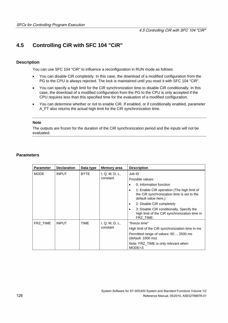
SFCs for Controlling Program Execution 4.5 Controlling CiR with SFC 104 "CiR"
System Software for S7-300/400 System and Standard Functions Volume 1/2 126 Reference Manual, 05/2010, A5E02789976-01
4.5 Controlling CiR with SFC 104 "CiR"
Description You can use SFC 104 "CiR" to influence a reconfiguration in RUN mode as follows:
• You can disable CiR completely. In this case, the download of a modified configuration from the PG to the CPU is always rejected. The lock is maintained until you reset it with SFC 104 "CiR".
• You can specify a high limit for the CiR synchronization time to disable CiR conditionally. In this case, the download of a modified configuration from the PG to the CPU is only accepted if the CPU requires less than this specified time for the evaluation of a modified configuration.
• You can determine whether or not to enable CiR. If enabled, or if conditionally enabled, parameter A_FT also returns the actual high limit for the CiR synchronization time.
Note
The outputs are frozen for the duration of the CiR synchronization period and the inputs will not be evaluated.
Parameters Parameter Declaration Data type Memory area Description
MODE INPUT BYTE I, Q, M, D, L, constant
Job ID Possible values: • 0: Information function • 1: Enable CiR operation (The high limit of
the CiR synchronization time is set to the default value here.)
• 2: Disable CiR completely • 3: Disable CiR conditionally. Specify the
high limit of the CiR synchronization time in FRZ_TIME.
FRZ_TIME INPUT TIME I, Q, M, D, L, constant
"freeze time" High limit of the CiR synchronization time in ms Permitted range of values: 60 ... 2500 ms (default: 1000 ms) Note: FRZ_TIME is only relevant when MODE=3.
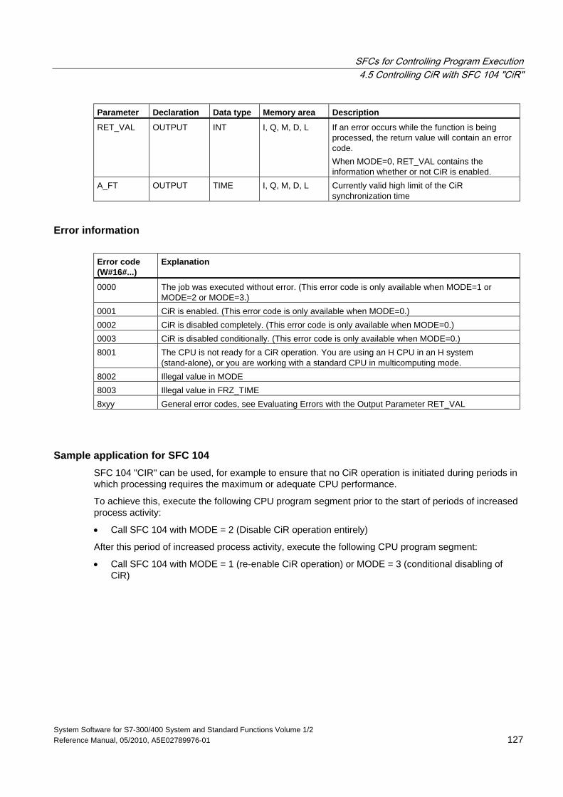
SFCs for Controlling Program Execution 4.5 Controlling CiR with SFC 104 "CiR"
System Software for S7-300/400 System and Standard Functions Volume 1/2 Reference Manual, 05/2010, A5E02789976-01 127
Parameter Declaration Data type Memory area Description
RET_VAL OUTPUT INT I, Q, M, D, L If an error occurs while the function is being processed, the return value will contain an error code. When MODE=0, RET_VAL contains the information whether or not CiR is enabled.
A_FT OUTPUT TIME I, Q, M, D, L Currently valid high limit of the CiR synchronization time
Error information Error code (W#16#...)
Explanation
0000 The job was executed without error. (This error code is only available when MODE=1 or MODE=2 or MODE=3.)
0001 CiR is enabled. (This error code is only available when MODE=0.) 0002 CiR is disabled completely. (This error code is only available when MODE=0.) 0003 CiR is disabled conditionally. (This error code is only available when MODE=0.) 8001 The CPU is not ready for a CiR operation. You are using an H CPU in an H system
(stand-alone), or you are working with a standard CPU in multicomputing mode. 8002 Illegal value in MODE 8003 Illegal value in FRZ_TIME 8xyy General error codes, see Evaluating Errors with the Output Parameter RET_VAL
Sample application for SFC 104 SFC 104 "CIR" can be used, for example to ensure that no CiR operation is initiated during periods in which processing requires the maximum or adequate CPU performance.
To achieve this, execute the following CPU program segment prior to the start of periods of increased process activity:
• Call SFC 104 with MODE = 2 (Disable CiR operation entirely)
After this period of increased process activity, execute the following CPU program segment:
• Call SFC 104 with MODE = 1 (re-enable CiR operation) or MODE = 3 (conditional disabling of CiR)
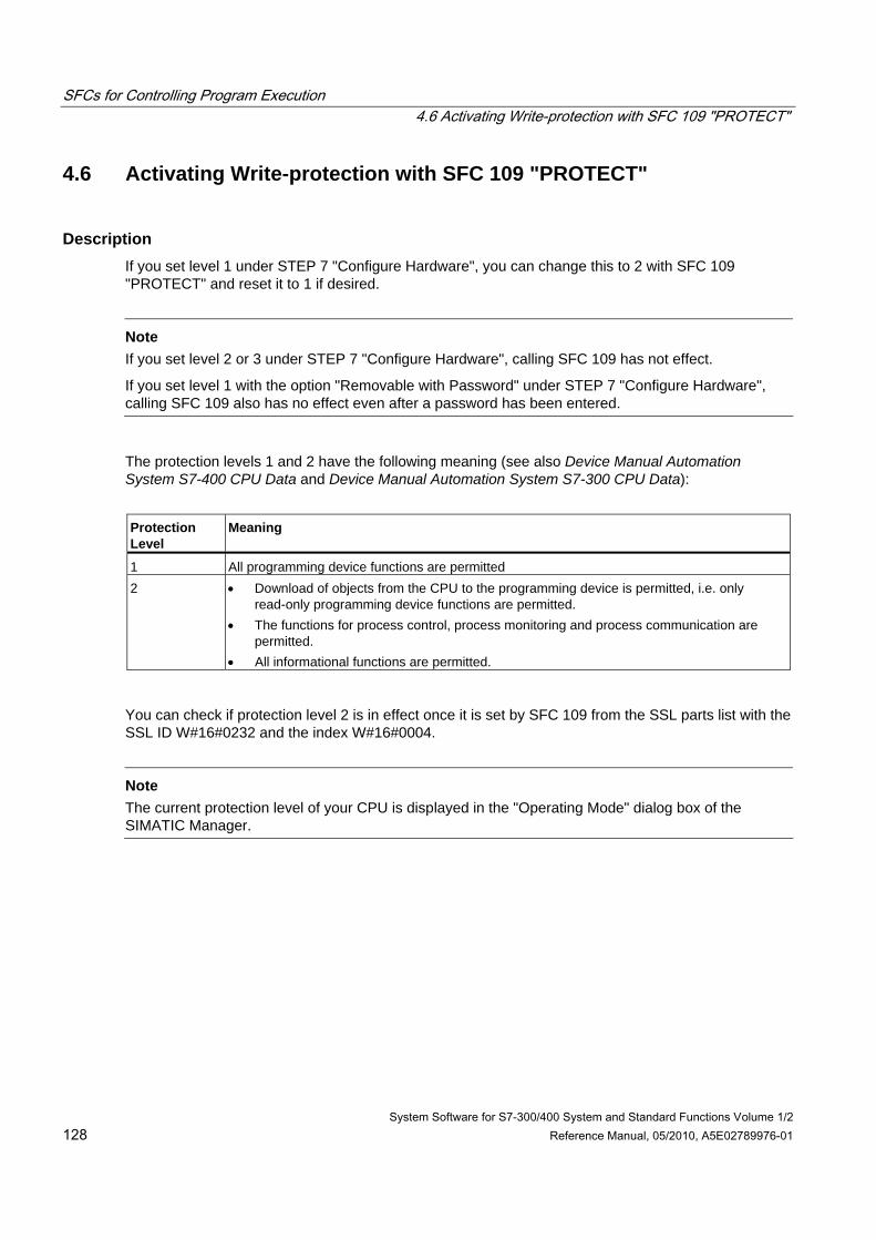
SFCs for Controlling Program Execution 4.6 Activating Write-protection with SFC 109 "PROTECT"
System Software for S7-300/400 System and Standard Functions Volume 1/2 128 Reference Manual, 05/2010, A5E02789976-01
4.6 Activating Write-protection with SFC 109 "PROTECT"
Description If you set level 1 under STEP 7 "Configure Hardware", you can change this to 2 with SFC 109 "PROTECT" and reset it to 1 if desired.
Note
If you set level 2 or 3 under STEP 7 "Configure Hardware", calling SFC 109 has not effect.
If you set level 1 with the option "Removable with Password" under STEP 7 "Configure Hardware", calling SFC 109 also has no effect even after a password has been entered.
The protection levels 1 and 2 have the following meaning (see also Device Manual Automation System S7-400 CPU Data and Device Manual Automation System S7-300 CPU Data):
Protection Level
Meaning
1 All programming device functions are permitted 2 • Download of objects from the CPU to the programming device is permitted, i.e. only
read-only programming device functions are permitted. • The functions for process control, process monitoring and process communication are
permitted. • All informational functions are permitted.
You can check if protection level 2 is in effect once it is set by SFC 109 from the SSL parts list with the SSL ID W#16#0232 and the index W#16#0004.
Note
The current protection level of your CPU is displayed in the "Operating Mode" dialog box of the SIMATIC Manager.
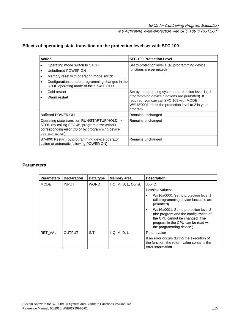
SFCs for Controlling Program Execution 4.6 Activating Write-protection with SFC 109 "PROTECT"
System Software for S7-300/400 System and Standard Functions Volume 1/2 Reference Manual, 05/2010, A5E02789976-01 129
Effects of operating state transition on the protection level set with SFC 109 Action SFC 109 Protection Level
• Operating mode switch to STOP • Unbuffered POWER ON • Memory reset with operating mode switch • Configurations and/or programming changes in the
STOP operating mode of the S7-400 CPU
Set to protection level 1 (all programming device functions are permitted)
• Cold restart • Warm restart
Set by the operating system to protection level 1 (all programming device functions are permitted). If required, you can call SFC 109 with MODE = W#16#0001 to set the protection level to 2 in your program.
Buffered POWER ON Remains unchanged Operating state transition RUN/STARTUP/HOLD -> STOP (by calling SFC 46, program error without corresponding error OB or by programming device operator action)
Remains unchanged
S7-400: Restart (by programming device operator action or automatic following POWER ON)
Remains unchanged
Parameters Parameters Declaration Data type Memory area Description
MODE INPUT WORD I, Q, M, D, L, Const. Job ID Possible values: • W#16#0000: Set to protection level 1
(all programming device functions are permitted)
• W#16#0001: Set to protection level 2 (the program and the configuration of the CPU cannot be changed. The program in the CPU can be read with the programming device.)
RET_VAL OUTPUT INT I, Q, M, D, L Return value If an error occurs during the execution of the function, the return value contains the error information.
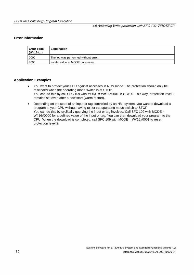
SFCs for Controlling Program Execution 4.6 Activating Write-protection with SFC 109 "PROTECT"
System Software for S7-300/400 System and Standard Functions Volume 1/2 130 Reference Manual, 05/2010, A5E02789976-01
Error Information Error code (W#16#...)
Explanation
0000 The job was performed without error. 8090 Invalid value at MODE parameter.
Application Examples • You want to protect your CPU against accesses in RUN mode. The protection should only be
rescinded when the operating mode switch is at STOP. You can do this by call SFC 109 with MODE = W#16#0001 in OB100. This way, protection level 2 remains set even after a new start (warm restart).
• Depending on the state of an input or tag controlled by an HMI system, you want to download a program to your CPU without having to set the operating mode switch to STOP. You can do this by cyclically querying the input or tag involved. Call SFC 109 with MODE = W#16#0000 for a defined value of the input or tag. You can then download your program to the CPU. When the download is completed, call SFC 109 with MODE = W#16#0001 to reset protection level 2.
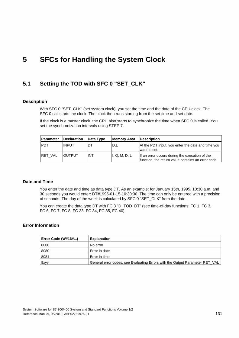
System Software for S7-300/400 System and Standard Functions Volume 1/2 Reference Manual, 05/2010, A5E02789976-01 131
5 SFCs for Handling the System Clock
5.1 Setting the TOD with SFC 0 "SET_CLK"
Description With SFC 0 "SET_CLK" (set system clock), you set the time and the date of the CPU clock. The SFC 0 call starts the clock. The clock then runs starting from the set time and set date.
If the clock is a master clock, the CPU also starts to synchronize the time when SFC 0 is called. You set the synchronization intervals using STEP 7.
Parameter Declaration Data Type Memory Area Description
PDT INPUT DT D,L At the PDT input, you enter the date and time you want to set.
RET_VAL OUTPUT INT I, Q, M, D, L If an error occurs during the execution of the function, the return value contains an error code.
Date and Time You enter the date and time as data type DT. As an example: for January 15th, 1995, 10:30 a.m. and 30 seconds you would enter: DT#1995-01-15-10:30:30. The time can only be entered with a precision of seconds. The day of the week is calculated by SFC 0 "SET_CLK" from the date.
You can create the data type DT with FC 3 "D_TOD_DT" (see time-of-day functions: FC 1, FC 3, FC 6, FC 7, FC 8, FC 33, FC 34, FC 35, FC 40).
Error Information Error Code (W#16#...) Explanation
0000 No error 8080 Error in date 8081 Error in time 8xyy General error codes, see Evaluating Errors with the Output Parameter RET_VAL
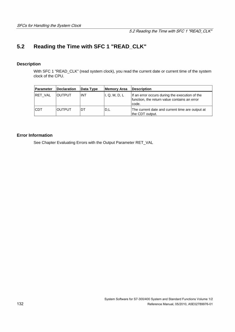
SFCs for Handling the System Clock 5.2 Reading the Time with SFC 1 "READ_CLK"
System Software for S7-300/400 System and Standard Functions Volume 1/2 132 Reference Manual, 05/2010, A5E02789976-01
5.2 Reading the Time with SFC 1 "READ_CLK"
Description With SFC 1 "READ_CLK" (read system clock), you read the current date or current time of the system clock of the CPU.
Parameter Declaration Data Type Memory Area Description
RET_VAL OUTPUT INT I, Q, M, D, L If an error occurs during the execution of the function, the return value contains an error code.
CDT OUTPUT DT D,L The current date and current time are output at the CDT output.
Error Information See Chapter Evaluating Errors with the Output Parameter RET_VAL
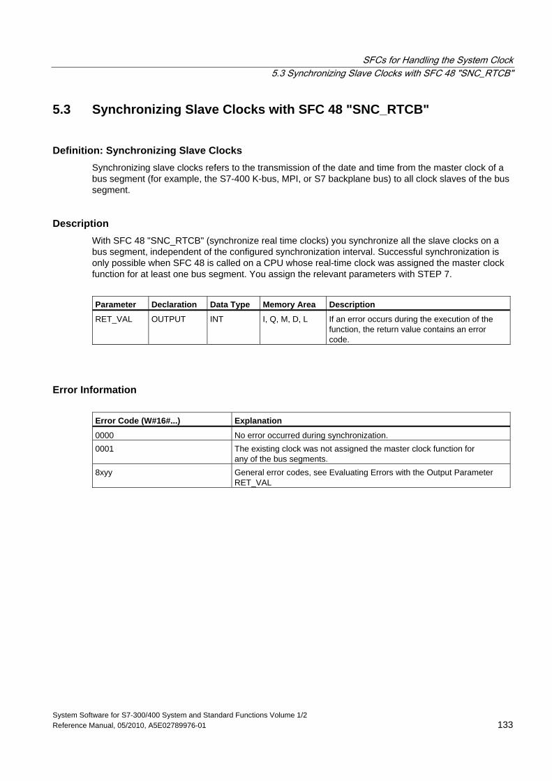
SFCs for Handling the System Clock 5.3 Synchronizing Slave Clocks with SFC 48 "SNC_RTCB"
System Software for S7-300/400 System and Standard Functions Volume 1/2 Reference Manual, 05/2010, A5E02789976-01 133
5.3 Synchronizing Slave Clocks with SFC 48 "SNC_RTCB"
Definition: Synchronizing Slave Clocks Synchronizing slave clocks refers to the transmission of the date and time from the master clock of a bus segment (for example, the S7-400 K-bus, MPI, or S7 backplane bus) to all clock slaves of the bus segment.
Description With SFC 48 "SNC_RTCB" (synchronize real time clocks) you synchronize all the slave clocks on a bus segment, independent of the configured synchronization interval. Successful synchronization is only possible when SFC 48 is called on a CPU whose real-time clock was assigned the master clock function for at least one bus segment. You assign the relevant parameters with STEP 7.
Parameter Declaration Data Type Memory Area Description
RET_VAL OUTPUT INT I, Q, M, D, L If an error occurs during the execution of the function, the return value contains an error code.
Error Information Error Code (W#16#...) Explanation
0000 No error occurred during synchronization. 0001 The existing clock was not assigned the master clock function for
any of the bus segments. 8xyy General error codes, see Evaluating Errors with the Output Parameter
RET_VAL
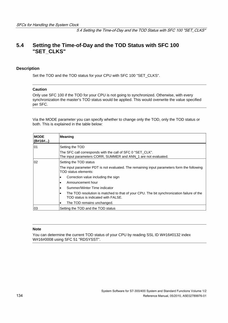
SFCs for Handling the System Clock 5.4 Setting the Time-of-Day and the TOD Status with SFC 100 "SET_CLKS"
System Software for S7-300/400 System and Standard Functions Volume 1/2 134 Reference Manual, 05/2010, A5E02789976-01
5.4 Setting the Time-of-Day and the TOD Status with SFC 100 "SET_CLKS"
Description Set the TOD and the TOD status for your CPU with SFC 100 "SET_CLKS".
Caution
Only use SFC 100 if the TOD for your CPU is not going to synchronized. Otherwise, with every synchronization the master’s TOD status would be applied. This would overwrite the value specified per SFC.
Via the MODE parameter you can specify whether to change only the TOD, only the TOD status or both. This is explained in the table below:
MODE (B#16#...)
Meaning
01 Setting the TOD The SFC call corresponds with the call of SFC 0 "SET_CLK". The input parameters CORR, SUMMER and ANN_1 are not evaluated.
02 Setting the TOD status The input parameter PDT is not evaluated. The remaining input parameters form the following TOD status elements: • Correction value including the sign • Announcement hour • Summer/Winter Time indicator • The TOD resolution is matched to that of your CPU. The bit synchronization failure of the
TOD status is indicated with FALSE. • The TOD remains unchanged.
03 Setting the TOD and the TOD status
Note
You can determine the current TOD status of your CPU by reading SSL ID W#16#0132 index W#16#0008 using SFC 51 "RDSYSST".
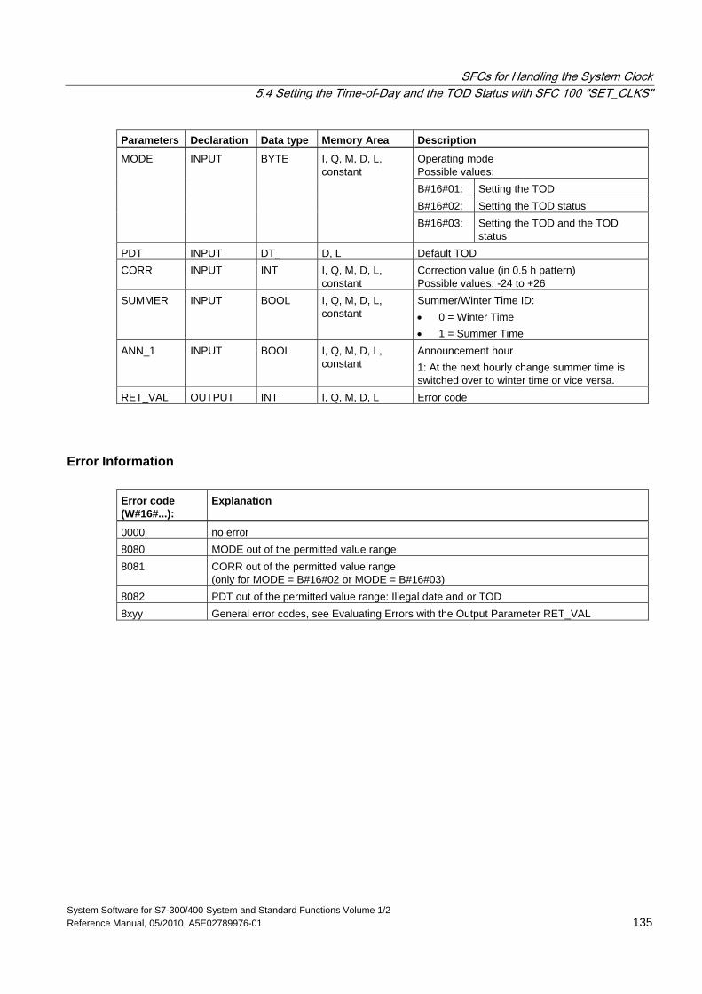
SFCs for Handling the System Clock 5.4 Setting the Time-of-Day and the TOD Status with SFC 100 "SET_CLKS"
System Software for S7-300/400 System and Standard Functions Volume 1/2 Reference Manual, 05/2010, A5E02789976-01 135
Parameters Declaration Data type Memory Area Description
Operating mode Possible values: B#16#01: Setting the TOD B#16#02: Setting the TOD status
MODE INPUT BYTE I, Q, M, D, L, constant
B#16#03: Setting the TOD and the TOD status
PDT INPUT DT D, L Default TOD CORR INPUT INT I, Q, M, D, L,
constant Correction value (in 0.5 h pattern) Possible values: -24 to +26
SUMMER INPUT BOOL I, Q, M, D, L, constant
Summer/Winter Time ID: • 0 = Winter Time • 1 = Summer Time
ANN_1 INPUT BOOL I, Q, M, D, L, constant
Announcement hour 1: At the next hourly change summer time is switched over to winter time or vice versa.
RET_VAL OUTPUT INT I, Q, M, D, L Error code
Error Information Error code (W#16#...):
Explanation
0000 no error 8080 MODE out of the permitted value range 8081 CORR out of the permitted value range
(only for MODE = B#16#02 or MODE = B#16#03) 8082 PDT out of the permitted value range: Illegal date and or TOD 8xyy General error codes, see Evaluating Errors with the Output Parameter RET_VAL
SFCs for Handling the System Clock 5.4 Setting the Time-of-Day and the TOD Status with SFC 100 "SET_CLKS"
System Software for S7-300/400 System and Standard Functions Volume 1/2 136 Reference Manual, 05/2010, A5E02789976-01
System Software for S7-300/400 System and Standard Functions Volume 1/2 Reference Manual, 05/2010, A5E02789976-01 137
6 SFCs for Handling Run-Time Meters
6.1 Runtime Meters
Introduction The CPUs have a number of runtime meters (refer to the data sheets of your CPUs).
• If your CPU is equipped with 16-bit runtime meters, you can set, start, stop or read them with the SFCs 2, 3 and 4.
• If your CPU is equipped with 32-bit runtime meters, you can set, start, stop or read them with SFC 101 "RTM".
Note
SFCs 2, 3 and 4 can also be used for 32-bit runtime meters. In this case however, the runtime meters operate in a 16-bit mode (Range of values: 0 to 32767 hours). See also: Data Record of Partial List Extract with SSL ID W#16#0132 Index W#16#000B.
Application You can use a runtime meter for a variety of applications:
• For measuring the runtime of the CPU
• For measuring the runtime of controlled equipment or connected devices.
SFCs for Handling Run-Time Meters 6.1 Runtime Meters
System Software for S7-300/400 System and Standard Functions Volume 1/2 138 Reference Manual, 05/2010, A5E02789976-01
Characteristics of the Runtime Meter When it is started, the runtime meter begins to count starting at the last recorded value. If you want it to start at a different initial value, you must explicitly specify this value (SFC 2 or SFC 101 with MODE=4). If the CPU changes to the STOP mode, or you stop the runtime meter, the CPU records the current value of the runtime meter. When a warm restart or a cold restart of the CPU is executed, the runtime meter must be restarted (SFC 3 or SFC 101 with MODE=1). After updating the operating system and after resetting the CPU to the state as shipped, the runtime meters are reset to the value 0.
Range of Values • CPU with 16-bit runtime meters: 0 to 32 767 hours
• CPU with 32-bit runtime meters: 0 to (2E31) -1 hours = 2.147.483.647 hours
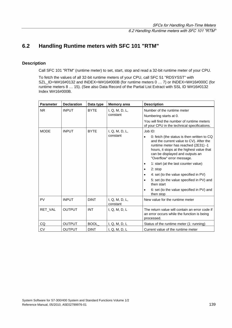
SFCs for Handling Run-Time Meters 6.2 Handling Runtime meters with SFC 101 "RTM"
System Software for S7-300/400 System and Standard Functions Volume 1/2 Reference Manual, 05/2010, A5E02789976-01 139
6.2 Handling Runtime meters with SFC 101 "RTM"
Description Call SFC 101 "RTM" (runtime meter) to set, start, stop and read a 32-bit runtime meter of your CPU.
To fetch the values of all 32-bit runtime meters of your CPU, call SFC 51 "RDSYSST" with SZL_ID=W#16#0132 and INDEX=W#16#000B (for runtime meters 0 … 7) or INDEX=W#16#000C (for runtime meters 8 … 15). (See also Data Record of the Partial List Extract with SSL ID W#16#0132 Index W#16#000B.
Parameter Declaration Data type Memory area Description
NR INPUT BYTE I, Q, M, D, L, constant
Number of the runtime meter Numbering starts at 0. You will find the number of runtime meters of your CPU in the technical specifications.
MODE INPUT BYTE I, Q, M, D, L, constant
Job ID: • 0: fetch (the status is then written to CQ
and the current value to CV). After the runtime meter has reached (2E31) -1 hours, it stops at the highest value that can be displayed and outputs an "Overflow" error message.
• 1: start (at the last counter value) • 2: stop • 4: set (to the value specified in PV) • 5: set (to the value specified in PV) and
then start • 6: set (to the value specified in PV) and
then stop PV INPUT DINT I, Q, M, D, L,
constant New value for the runtime meter
RET_VAL OUTPUT INT I, Q, M, D, L The return value will contain an error code if an error occurs while the function is being processed.
CQ OUTPUT BOOL I, Q, M, D, L Status of the runtime meter (1: running) CV OUTPUT DINT I, Q, M, D, L Current value of the runtime meter
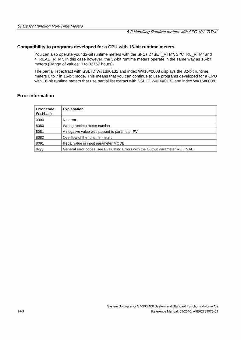
SFCs for Handling Run-Time Meters 6.2 Handling Runtime meters with SFC 101 "RTM"
System Software for S7-300/400 System and Standard Functions Volume 1/2 140 Reference Manual, 05/2010, A5E02789976-01
Compatibility to programs developed for a CPU with 16-bit runtime meters You can also operate your 32-bit runtime meters with the SFCs 2 "SET_RTM", 3 "CTRL_RTM" and 4 "READ_RTM". In this case however, the 32-bit runtime meters operate in the same way as 16-bit meters (Range of values: 0 to 32767 hours).
The partial list extract with SSL ID W#16#0132 and index W#16#0008 displays the 32-bit runtime meters 0 to 7 in 16-bit mode. This means that you can continue to use programs developed for a CPU with 16-bit runtime meters that use partial list extract with SSL ID W#16#0132 and index W#16#0008.
Error information Error code W#16#...)
Explanation
0000 No error 8080 Wrong runtime meter number 8081 A negative value was passed to parameter PV. 8082 Overflow of the runtime meter. 8091 Illegal value in input parameter MODE. 8xyy General error codes, see Evaluating Errors with the Output Parameter RET_VAL
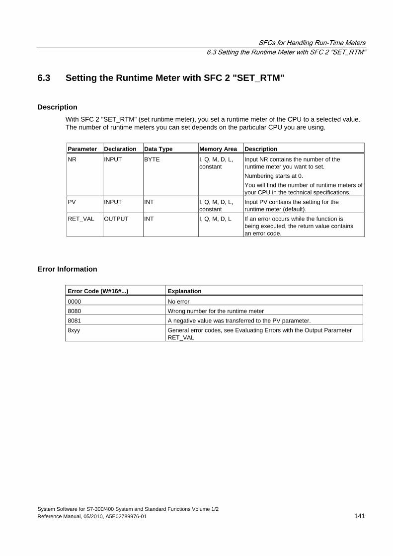
SFCs for Handling Run-Time Meters 6.3 Setting the Runtime Meter with SFC 2 "SET_RTM"
System Software for S7-300/400 System and Standard Functions Volume 1/2 Reference Manual, 05/2010, A5E02789976-01 141
6.3 Setting the Runtime Meter with SFC 2 "SET_RTM"
Description With SFC 2 "SET_RTM" (set runtime meter), you set a runtime meter of the CPU to a selected value. The number of runtime meters you can set depends on the particular CPU you are using.
Parameter Declaration Data Type Memory Area Description
NR INPUT BYTE I, Q, M, D, L, constant
Input NR contains the number of the runtime meter you want to set. Numbering starts at 0. You will find the number of runtime meters of your CPU in the technical specifications.
PV INPUT INT I, Q, M, D, L, constant
Input PV contains the setting for the runtime meter (default).
RET_VAL OUTPUT INT I, Q, M, D, L If an error occurs while the function is being executed, the return value contains an error code.
Error Information Error Code (W#16#...) Explanation
0000 No error 8080 Wrong number for the runtime meter 8081 A negative value was transferred to the PV parameter. 8xyy General error codes, see Evaluating Errors with the Output Parameter
RET_VAL
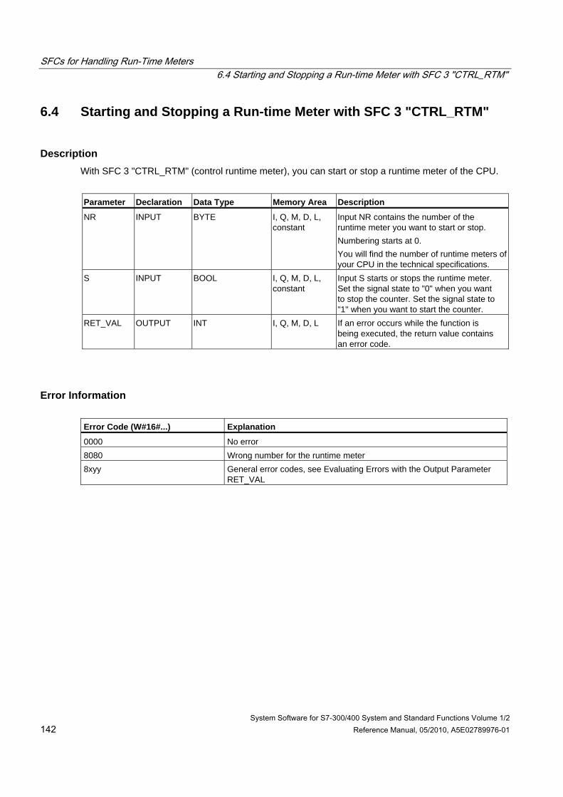
SFCs for Handling Run-Time Meters 6.4 Starting and Stopping a Run-time Meter with SFC 3 "CTRL_RTM"
System Software for S7-300/400 System and Standard Functions Volume 1/2 142 Reference Manual, 05/2010, A5E02789976-01
6.4 Starting and Stopping a Run-time Meter with SFC 3 "CTRL_RTM"
Description With SFC 3 "CTRL_RTM" (control runtime meter), you can start or stop a runtime meter of the CPU.
Parameter Declaration Data Type Memory Area Description
NR INPUT BYTE I, Q, M, D, L, constant
Input NR contains the number of the runtime meter you want to start or stop. Numbering starts at 0. You will find the number of runtime meters of your CPU in the technical specifications.
S INPUT BOOL I, Q, M, D, L, constant
Input S starts or stops the runtime meter. Set the signal state to "0" when you want to stop the counter. Set the signal state to "1" when you want to start the counter.
RET_VAL OUTPUT INT I, Q, M, D, L If an error occurs while the function is being executed, the return value contains an error code.
Error Information Error Code (W#16#...) Explanation
0000 No error 8080 Wrong number for the runtime meter 8xyy General error codes, see Evaluating Errors with the Output Parameter
RET_VAL
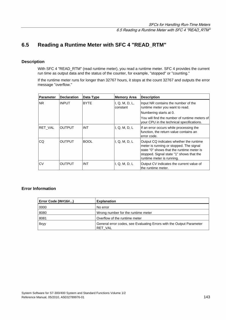
SFCs for Handling Run-Time Meters 6.5 Reading a Runtime Meter with SFC 4 "READ_RTM"
System Software for S7-300/400 System and Standard Functions Volume 1/2 Reference Manual, 05/2010, A5E02789976-01 143
6.5 Reading a Runtime Meter with SFC 4 "READ_RTM"
Description With SFC 4 "READ_RTM" (read runtime meter), you read a runtime meter. SFC 4 provides the current run time as output data and the status of the counter, for example, "stopped" or "counting."
If the runtime meter runs for longer than 32767 hours, it stops at the count 32767 and outputs the error message "overflow."
Parameter Declaration Data Type Memory Area Description
NR INPUT BYTE I, Q, M, D, L, constant
Input NR contains the number of the runtime meter you want to read. Numbering starts at 0. You will find the number of runtime meters of your CPU in the technical specifications.
RET_VAL OUTPUT INT I, Q, M, D, L If an error occurs while processing the function, the return value contains an error code.
CQ OUTPUT BOOL I, Q, M, D, L Output CQ indicates whether the runtime meter is running or stopped. The signal state "0" shows that the runtime meter is stopped. Signal state "1" shows that the runtime meter is running.
CV OUTPUT INT I, Q, M, D, L Output CV indicates the current value of the runtime meter.
Error Information Error Code (W#16#...) Explanation
0000 No error 8080 Wrong number for the runtime meter 8081 Overflow of the runtime meter 8xyy General error codes, see Evaluating Errors with the Output Parameter
RET_VAL
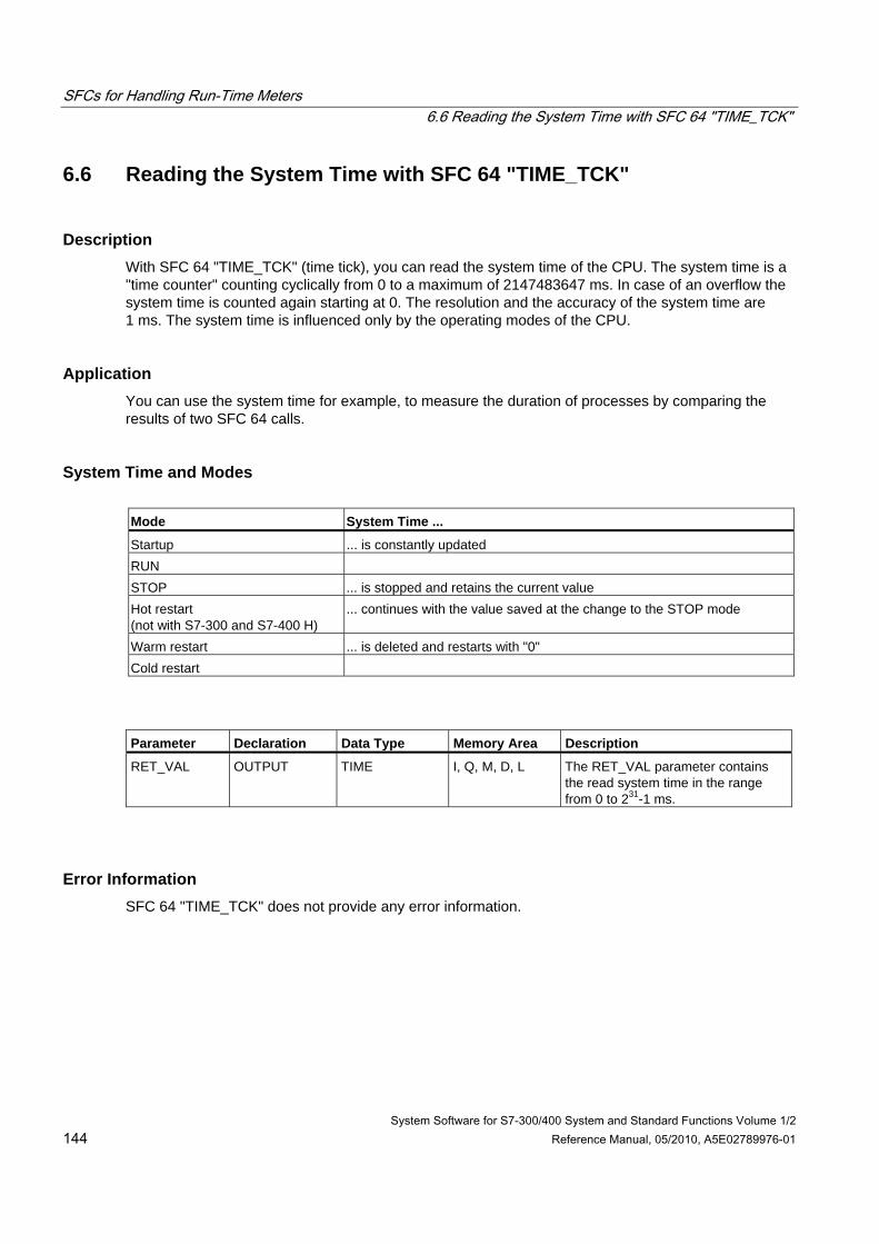
SFCs for Handling Run-Time Meters 6.6 Reading the System Time with SFC 64 "TIME_TCK"
System Software for S7-300/400 System and Standard Functions Volume 1/2 144 Reference Manual, 05/2010, A5E02789976-01
6.6 Reading the System Time with SFC 64 "TIME_TCK"
Description With SFC 64 "TIME_TCK" (time tick), you can read the system time of the CPU. The system time is a "time counter" counting cyclically from 0 to a maximum of 2147483647 ms. In case of an overflow the system time is counted again starting at 0. The resolution and the accuracy of the system time are 1 ms. The system time is influenced only by the operating modes of the CPU.
Application You can use the system time for example, to measure the duration of processes by comparing the results of two SFC 64 calls.
System Time and Modes Mode System Time ...
Startup ... is constantly updated RUN STOP ... is stopped and retains the current value Hot restart (not with S7-300 and S7-400 H)
... continues with the value saved at the change to the STOP mode
Warm restart ... is deleted and restarts with "0" Cold restart
Parameter Declaration Data Type Memory Area Description
RET_VAL OUTPUT TIME I, Q, M, D, L The RET_VAL parameter contains the read system time in the range from 0 to 231-1 ms.
Error Information SFC 64 "TIME_TCK" does not provide any error information.
System Software for S7-300/400 System and Standard Functions Volume 1/2 Reference Manual, 05/2010, A5E02789976-01 145
7 SFCs/SFBs for Transferring Data Records
7.1 Writing and Reading Data Records
Principle Some modules have a write-only system data area to which your program can transfer data records. This area contains data records with numbers from 0 to a maximum of 240. Not every module contains all of the data records (see following table).
Other modules have a read-only system data area in which your program can read data records. This area contains data records with numbers from 0 to a maximum of 240. Not every module contains all of the data records (see following table).
Note
There are modules that have both system data areas. These are physically separate areas and all they have in common is their logical structure.
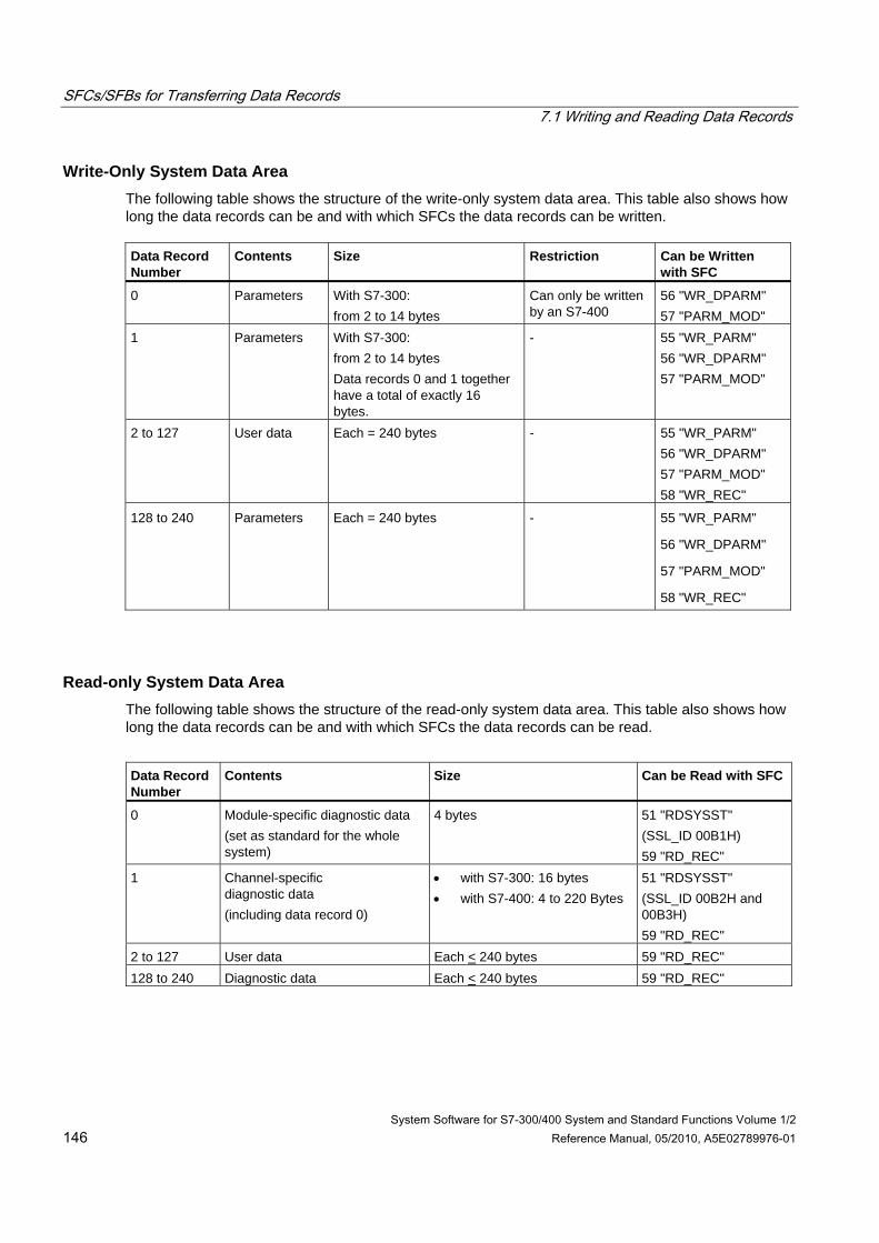
SFCs/SFBs for Transferring Data Records 7.1 Writing and Reading Data Records
System Software for S7-300/400 System and Standard Functions Volume 1/2 146 Reference Manual, 05/2010, A5E02789976-01
Write-Only System Data Area The following table shows the structure of the write-only system data area. This table also shows how long the data records can be and with which SFCs the data records can be written. Data Record Number
Contents
Size
Restriction
Can be Written with SFC
0 Parameters With S7-300: from 2 to 14 bytes
Can only be written by an S7-400
56 "WR_DPARM" 57 "PARM_MOD"
1 Parameters With S7-300: from 2 to 14 bytes Data records 0 and 1 together have a total of exactly 16 bytes.
- 55 "WR_PARM" 56 "WR_DPARM" 57 "PARM_MOD"
2 to 127 User data Each = 240 bytes - 55 "WR_PARM" 56 "WR_DPARM" 57 "PARM_MOD" 58 "WR_REC"
128 to 240 Parameters Each = 240 bytes - 55 "WR_PARM"
56 "WR_DPARM"
57 "PARM_MOD"
58 "WR_REC"
Read-only System Data Area The following table shows the structure of the read-only system data area. This table also shows how long the data records can be and with which SFCs the data records can be read.
Data Record Number
Contents
Size
Can be Read with SFC
0 Module-specific diagnostic data (set as standard for the whole system)
4 bytes 51 "RDSYSST" (SSL_ID 00B1H) 59 "RD_REC"
1 Channel-specific diagnostic data (including data record 0)
• with S7-300: 16 bytes • with S7-400: 4 to 220 Bytes
51 "RDSYSST" (SSL_ID 00B2H and 00B3H) 59 "RD_REC"
2 to 127 User data Each < 240 bytes 59 "RD_REC" 128 to 240 Diagnostic data Each < 240 bytes 59 "RD_REC"
SFCs/SFBs for Transferring Data Records 7.1 Writing and Reading Data Records
System Software for S7-300/400 System and Standard Functions Volume 1/2 Reference Manual, 05/2010, A5E02789976-01 147
System Resources If you start several asynchronous data record transfers one after the other with only short intervals between them, the allocation of system resources by the operating system ensures that all the jobs are executed and that they do not interfere with each other.
If all the available system resources are being used, this is indicated in RET_VAL. You can remedy this temporary error situation by simply repeating the job.
The maximum number of "simultaneously" active SFC jobs depends on the CPU. Refer to /72/, /101/ and /102/ for more detailed information.
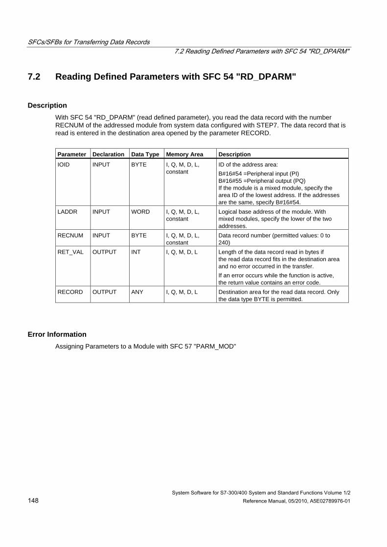
SFCs/SFBs for Transferring Data Records 7.2 Reading Defined Parameters with SFC 54 "RD_DPARM"
System Software for S7-300/400 System and Standard Functions Volume 1/2 148 Reference Manual, 05/2010, A5E02789976-01
7.2 Reading Defined Parameters with SFC 54 "RD_DPARM"
Description With SFC 54 "RD_DPARM" (read defined parameter), you read the data record with the number RECNUM of the addressed module from system data configured with STEP7. The data record that is read is entered in the destination area opened by the parameter RECORD.
Parameter Declaration Data Type Memory Area Description
IOID INPUT BYTE I, Q, M, D, L, constant
ID of the address area: B#16#54 =Peripheral input (PI) B#16#55 =Peripheral output (PQ) If the module is a mixed module, specify the area ID of the lowest address. If the addresses are the same, specify B#16#54.
LADDR INPUT WORD I, Q, M, D, L, constant
Logical base address of the module. With mixed modules, specify the lower of the two addresses.
RECNUM INPUT BYTE I, Q, M, D, L, constant
Data record number (permitted values: 0 to 240)
RET_VAL OUTPUT INT I, Q, M, D, L Length of the data record read in bytes if the read data record fits in the destination area and no error occurred in the transfer. If an error occurs while the function is active, the return value contains an error code.
RECORD OUTPUT ANY I, Q, M, D, L Destination area for the read data record. Only the data type BYTE is permitted.
Error Information Assigning Parameters to a Module with SFC 57 "PARM_MOD"
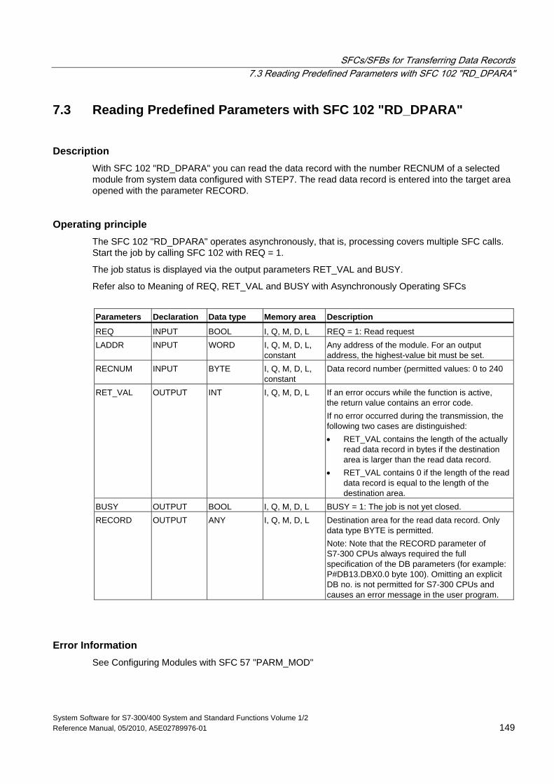
SFCs/SFBs for Transferring Data Records 7.3 Reading Predefined Parameters with SFC 102 "RD_DPARA"
System Software for S7-300/400 System and Standard Functions Volume 1/2 Reference Manual, 05/2010, A5E02789976-01 149
7.3 Reading Predefined Parameters with SFC 102 "RD_DPARA"
Description With SFC 102 "RD_DPARA" you can read the data record with the number RECNUM of a selected module from system data configured with STEP7. The read data record is entered into the target area opened with the parameter RECORD.
Operating principle The SFC 102 "RD_DPARA" operates asynchronously, that is, processing covers multiple SFC calls. Start the job by calling SFC 102 with REQ = 1.
The job status is displayed via the output parameters RET_VAL and BUSY.
Refer also to Meaning of REQ, RET_VAL and BUSY with Asynchronously Operating SFCs
Parameters Declaration Data type Memory area Description
REQ INPUT BOOL I, Q, M, D, L REQ = 1: Read request LADDR INPUT WORD I, Q, M, D, L,
constant Any address of the module. For an output address, the highest-value bit must be set.
RECNUM INPUT BYTE I, Q, M, D, L, constant
Data record number (permitted values: 0 to 240
RET_VAL OUTPUT INT I, Q, M, D, L If an error occurs while the function is active, the return value contains an error code. If no error occurred during the transmission, the following two cases are distinguished: • RET_VAL contains the length of the actually
read data record in bytes if the destination area is larger than the read data record.
• RET_VAL contains 0 if the length of the read data record is equal to the length of the destination area.
BUSY OUTPUT BOOL I, Q, M, D, L BUSY = 1: The job is not yet closed. RECORD OUTPUT ANY I, Q, M, D, L Destination area for the read data record. Only
data type BYTE is permitted. Note: Note that the RECORD parameter of S7-300 CPUs always required the full specification of the DB parameters (for example: P#DB13.DBX0.0 byte 100). Omitting an explicit DB no. is not permitted for S7-300 CPUs and causes an error message in the user program.
Error Information See Configuring Modules with SFC 57 "PARM_MOD"
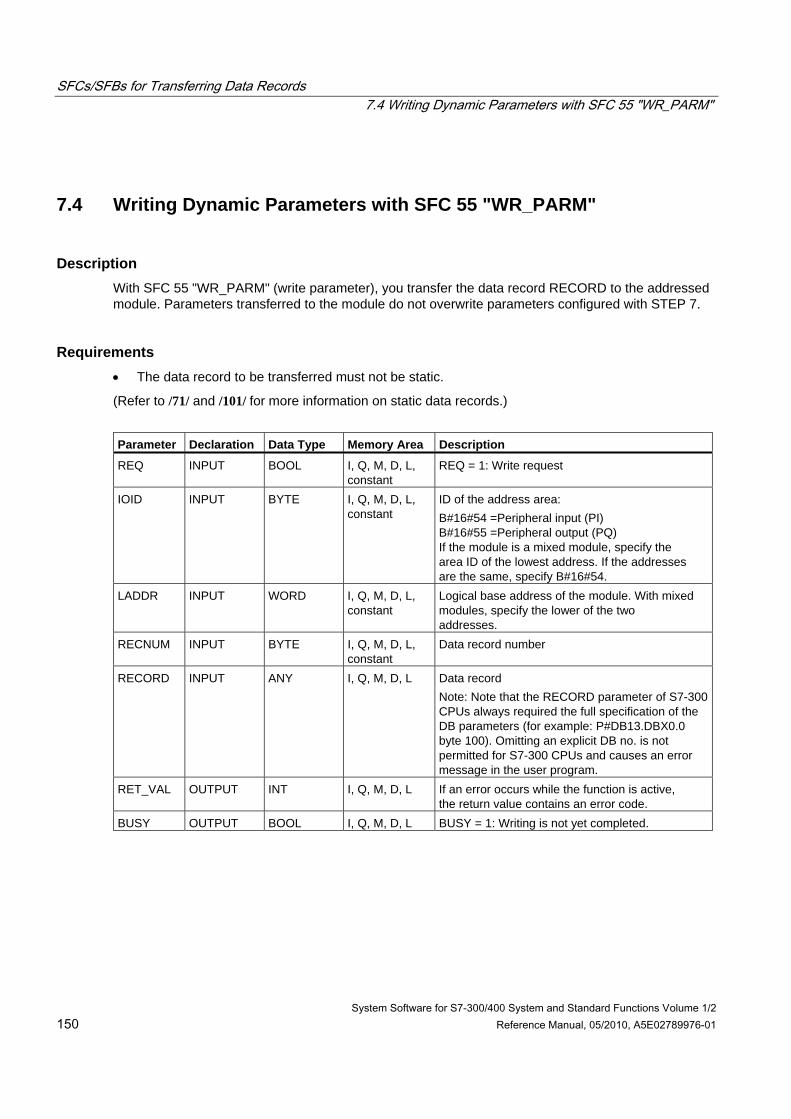
SFCs/SFBs for Transferring Data Records 7.4 Writing Dynamic Parameters with SFC 55 "WR_PARM"
System Software for S7-300/400 System and Standard Functions Volume 1/2 150 Reference Manual, 05/2010, A5E02789976-01
7.4 Writing Dynamic Parameters with SFC 55 "WR_PARM"
Description With SFC 55 "WR_PARM" (write parameter), you transfer the data record RECORD to the addressed module. Parameters transferred to the module do not overwrite parameters configured with STEP 7.
Requirements • The data record to be transferred must not be static.
(Refer to /71/ and /101/ for more information on static data records.)
Parameter Declaration Data Type Memory Area Description
REQ INPUT BOOL I, Q, M, D, L, constant
REQ = 1: Write request
IOID INPUT BYTE I, Q, M, D, L, constant
ID of the address area: B#16#54 =Peripheral input (PI) B#16#55 =Peripheral output (PQ) If the module is a mixed module, specify the area ID of the lowest address. If the addresses are the same, specify B#16#54.
LADDR INPUT WORD
I, Q, M, D, L, constant
Logical base address of the module. With mixed modules, specify the lower of the two addresses.
RECNUM INPUT BYTE I, Q, M, D, L, constant
Data record number
RECORD INPUT ANY I, Q, M, D, L Data record Note: Note that the RECORD parameter of S7-300 CPUs always required the full specification of the DB parameters (for example: P#DB13.DBX0.0 byte 100). Omitting an explicit DB no. is not permitted for S7-300 CPUs and causes an error message in the user program.
RET_VAL OUTPUT INT I, Q, M, D, L If an error occurs while the function is active, the return value contains an error code.
BUSY OUTPUT BOOL I, Q, M, D, L BUSY = 1: Writing is not yet completed.
SFCs/SFBs for Transferring Data Records 7.4 Writing Dynamic Parameters with SFC 55 "WR_PARM"
System Software for S7-300/400 System and Standard Functions Volume 1/2 Reference Manual, 05/2010, A5E02789976-01 151
Input Parameter RECORD The data to be transferred are read from the parameter RECORD during the first SFC call. If the transfer of the data record takes longer than the duration of a call, the contents of the parameter RECORD are no longer relevant for the subsequent SFC calls (for the same job).
Error Information Assigning Parameters to a Module with SFC 57 "PARM_MOD"
Note
(S7-400 only) If the general error W#16#8544 occurs, this only indicates that access to at least one byte of the I/O memory area containing the data record was denied. The data transfer was continued.
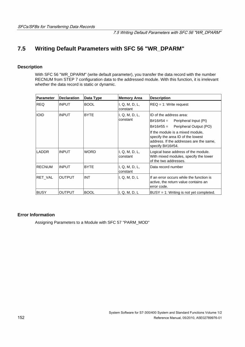
SFCs/SFBs for Transferring Data Records 7.5 Writing Default Parameters with SFC 56 "WR_DPARM"
System Software for S7-300/400 System and Standard Functions Volume 1/2 152 Reference Manual, 05/2010, A5E02789976-01
7.5 Writing Default Parameters with SFC 56 "WR_DPARM"
Description With SFC 56 "WR_DPARM" (write default parameter), you transfer the data record with the number RECNUM from STEP 7 configuration data to the addressed module. With this function, it is irrelevant whether the data record is static or dynamic.
Parameter Declaration Data Type Memory Area Description
REQ INPUT BOOL I, Q, M, D, L, constant
REQ = 1: Write request
IOID INPUT BYTE I, Q, M, D, L, constant
ID of the address area: B#16#54 = Peripheral Input (PI) B#16#55 = Peripheral Output (PO) If the module is a mixed module, specify the area ID of the lowest address. If the addresses are the same, specify B#16#54.
LADDR INPUT WORD I, Q, M, D, L, constant
Logical base address of the module. With mixed modules, specify the lower of the two addresses.
RECNUM INPUT BYTE I, Q, M, D, L, constant
Data record number
RET_VAL OUTPUT INT I, Q, M, D, L If an error occurs while the function is active, the return value contains an error code.
BUSY OUTPUT BOOL I, Q, M, D, L BUSY = 1: Writing is not yet completed.
Error Information Assigning Parameters to a Module with SFC 57 "PARM_MOD"
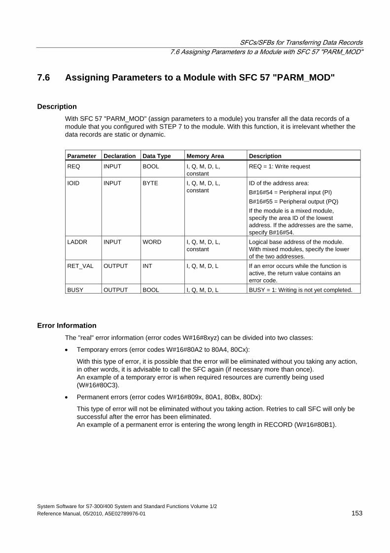
SFCs/SFBs for Transferring Data Records 7.6 Assigning Parameters to a Module with SFC 57 "PARM_MOD"
System Software for S7-300/400 System and Standard Functions Volume 1/2 Reference Manual, 05/2010, A5E02789976-01 153
7.6 Assigning Parameters to a Module with SFC 57 "PARM_MOD"
Description With SFC 57 "PARM_MOD" (assign parameters to a module) you transfer all the data records of a module that you configured with STEP 7 to the module. With this function, it is irrelevant whether the data records are static or dynamic.
Parameter Declaration Data Type Memory Area Description
REQ INPUT BOOL I, Q, M, D, L, constant
REQ = 1: Write request
IOID INPUT BYTE I, Q, M, D, L, constant
ID of the address area: B#16#54 = Peripheral input (PI) B#16#55 = Peripheral output (PQ) If the module is a mixed module, specify the area ID of the lowest address. If the addresses are the same, specify B#16#54.
LADDR INPUT WORD I, Q, M, D, L, constant
Logical base address of the module. With mixed modules, specify the lower of the two addresses.
RET_VAL OUTPUT INT I, Q, M, D, L If an error occurs while the function is active, the return value contains an error code.
BUSY OUTPUT BOOL I, Q, M, D, L BUSY = 1: Writing is not yet completed.
Error Information The "real" error information (error codes W#16#8xyz) can be divided into two classes:
• Temporary errors (error codes W#16#80A2 to 80A4, 80Cx):
With this type of error, it is possible that the error will be eliminated without you taking any action, in other words, it is advisable to call the SFC again (if necessary more than once). An example of a temporary error is when required resources are currently being used (W#16#80C3).
• Permanent errors (error codes W#16#809x, 80A1, 80Bx, 80Dx):
This type of error will not be eliminated without you taking action. Retries to call SFC will only be successful after the error has been eliminated. An example of a permanent error is entering the wrong length in RECORD (W#16#80B1).
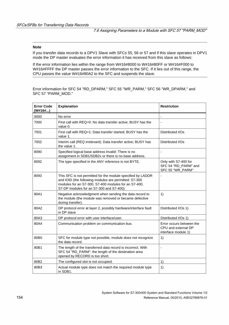
SFCs/SFBs for Transferring Data Records 7.6 Assigning Parameters to a Module with SFC 57 "PARM_MOD"
System Software for S7-300/400 System and Standard Functions Volume 1/2 154 Reference Manual, 05/2010, A5E02789976-01
Note If you transfer data records to a DPV1 Slave with SFCs 55, 56 or 57 and if this slave operates in DPV1 mode the DP master evaluates the error information it has received from this slave as follows:
If the error information lies within the range from W#16#8000 to W#16#80FF or W#16#F000 to W#16#FFFF the DP master passes the error information to the SFC. If it lies out of this range, the CPU passes the value W#16#80A2 to the SFC and suspends the slave.
Error information for SFC 54 "RD_DPARM," SFC 55 "WR_PARM," SFC 56 "WR_DPARM," and SFC 57 "PARM_MOD."
Error Code (W#16#...)
Explanation
Restriction
0000 No error - 7000 First call with REQ=0: No data transfer active; BUSY has the
value 0. -
7001 First call with REQ=1: Data transfer started; BUSY has the value 1.
Distributed I/Os
7002 Interim call (REQ irrelevant): Data transfer active; BUSY has the value 1.
Distributed I/Os
8090 Specified logical base address invalid: There is no assignment in SDB1/SDB2x or there is no base address.
-
8092 The type specified in the ANY reference is not BYTE. Only with S7-400 for SFC 54 "RD_PARM" and SFC 55 "WR_PARM"
8093 This SFC is not permitted for the module specified by LADDR and IOID (the following modules are permitted: S7-300 modules for an S7-300, S7-400 modules for an S7-400, S7-DP modules for an S7-300 and S7-400).
-
80A1 Negative acknowledgment when sending the data record to the module (the module was removed or became defective during transfer).
1)
80A2 DP protocol error at layer 2, possibly hardware/interface fault in DP slave
Distributed I/Os 1)
80A3 DP protocol error with user interface/user. Distributed I/Os 1) 80A4 Communication problem on communication bus. Error occurs between the
CPU and external DP interface module 1)
80B0 SFC for module type not possible, module does not recognize the data record.
1)
80B1 The length of the transferred data record is incorrect. With SFC 54 "RD_PARM": the length of the destination area opened by RECORD is too short.
-
80B2 The configured slot is not occupied. 1) 80B3 Actual module type does not match the required module type
in SDB1. 1)
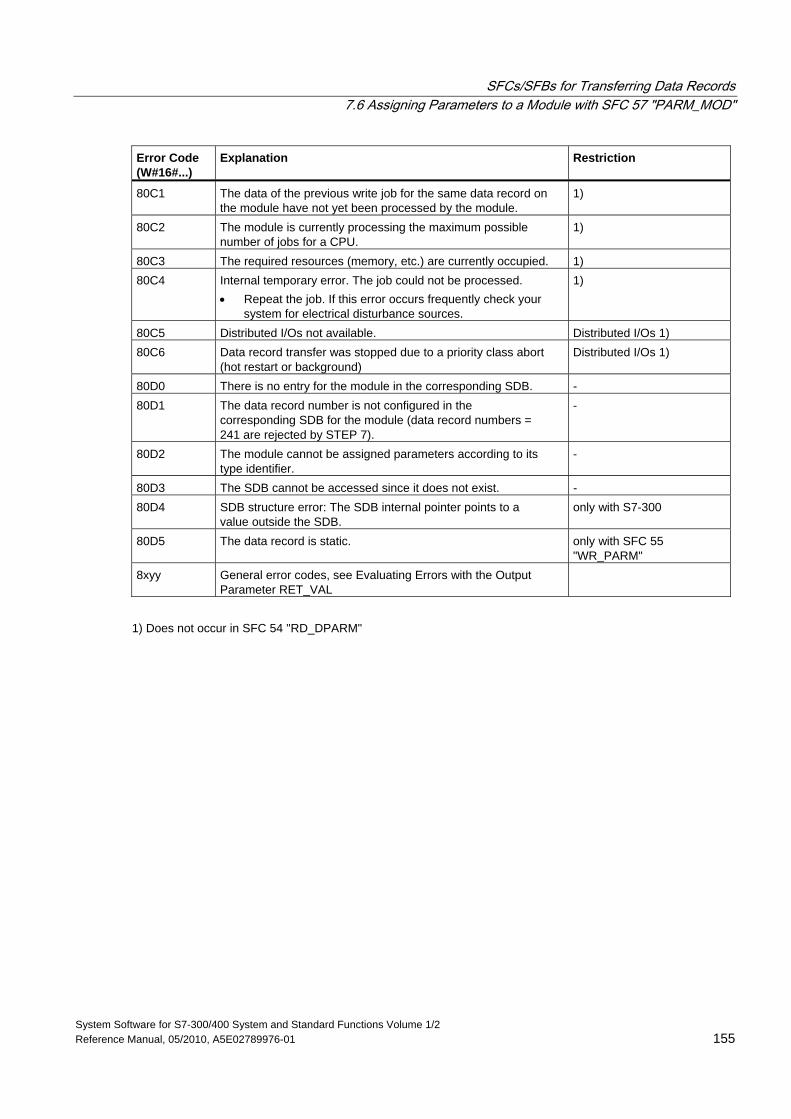
SFCs/SFBs for Transferring Data Records 7.6 Assigning Parameters to a Module with SFC 57 "PARM_MOD"
System Software for S7-300/400 System and Standard Functions Volume 1/2 Reference Manual, 05/2010, A5E02789976-01 155
Error Code (W#16#...)
Explanation
Restriction
80C1 The data of the previous write job for the same data record on the module have not yet been processed by the module.
1)
80C2 The module is currently processing the maximum possible number of jobs for a CPU.
1)
80C3 The required resources (memory, etc.) are currently occupied. 1) 80C4 Internal temporary error. The job could not be processed.
• Repeat the job. If this error occurs frequently check your system for electrical disturbance sources.
1)
80C5 Distributed I/Os not available. Distributed I/Os 1) 80C6 Data record transfer was stopped due to a priority class abort
(hot restart or background) Distributed I/Os 1)
80D0 There is no entry for the module in the corresponding SDB. - 80D1 The data record number is not configured in the
corresponding SDB for the module (data record numbers = 241 are rejected by STEP 7).
-
80D2 The module cannot be assigned parameters according to its type identifier.
-
80D3 The SDB cannot be accessed since it does not exist. - 80D4 SDB structure error: The SDB internal pointer points to a
value outside the SDB. only with S7-300
80D5 The data record is static. only with SFC 55 "WR_PARM"
8xyy General error codes, see Evaluating Errors with the Output Parameter RET_VAL
1) Does not occur in SFC 54 "RD_DPARM"
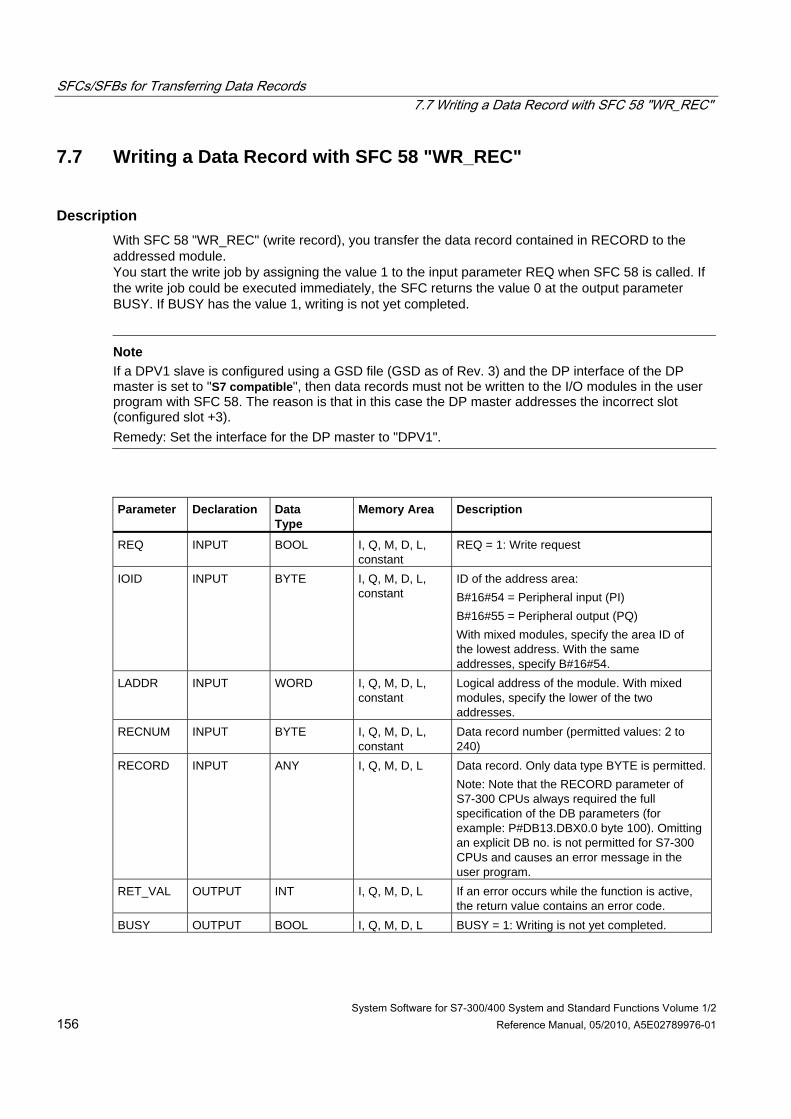
SFCs/SFBs for Transferring Data Records 7.7 Writing a Data Record with SFC 58 "WR_REC"
System Software for S7-300/400 System and Standard Functions Volume 1/2 156 Reference Manual, 05/2010, A5E02789976-01
7.7 Writing a Data Record with SFC 58 "WR_REC"
Description With SFC 58 "WR_REC" (write record), you transfer the data record contained in RECORD to the addressed module. You start the write job by assigning the value 1 to the input parameter REQ when SFC 58 is called. If the write job could be executed immediately, the SFC returns the value 0 at the output parameter BUSY. If BUSY has the value 1, writing is not yet completed.
Note
If a DPV1 slave is configured using a GSD file (GSD as of Rev. 3) and the DP interface of the DP master is set to "S7 compatible", then data records must not be written to the I/O modules in the user program with SFC 58. The reason is that in this case the DP master addresses the incorrect slot (configured slot +3). Remedy: Set the interface for the DP master to "DPV1".
Parameter
Declaration
Data Type
Memory Area
Description
REQ INPUT BOOL I, Q, M, D, L, constant
REQ = 1: Write request
IOID INPUT BYTE I, Q, M, D, L, constant
ID of the address area: B#16#54 = Peripheral input (PI) B#16#55 = Peripheral output (PQ) With mixed modules, specify the area ID of the lowest address. With the same addresses, specify B#16#54.
LADDR INPUT WORD I, Q, M, D, L, constant
Logical address of the module. With mixed modules, specify the lower of the two addresses.
RECNUM INPUT BYTE I, Q, M, D, L, constant
Data record number (permitted values: 2 to 240)
RECORD INPUT ANY I, Q, M, D, L Data record. Only data type BYTE is permitted.Note: Note that the RECORD parameter of S7-300 CPUs always required the full specification of the DB parameters (for example: P#DB13.DBX0.0 byte 100). Omitting an explicit DB no. is not permitted for S7-300 CPUs and causes an error message in the user program.
RET_VAL OUTPUT INT I, Q, M, D, L If an error occurs while the function is active, the return value contains an error code.
BUSY OUTPUT BOOL I, Q, M, D, L BUSY = 1: Writing is not yet completed.
SFCs/SFBs for Transferring Data Records 7.7 Writing a Data Record with SFC 58 "WR_REC"
System Software for S7-300/400 System and Standard Functions Volume 1/2 Reference Manual, 05/2010, A5E02789976-01 157
Input Parameter RECORD The data to be transferred are read from the parameter RECORD during the first SFC call. If the transfer of the data record takes longer than the duration of a call, the contents of the parameter RECORD are no longer relevant for the subsequent SFC calls (for the same job).
Error Information Reading a Data Record with SFC 59 "RD_REC"
Note
If the general error W#16#8544 occurs, this only indicates that access to at least one byte of the I/O memory area containing the data record was denied. The data transfer was continued.
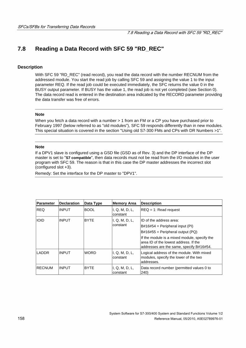
SFCs/SFBs for Transferring Data Records 7.8 Reading a Data Record with SFC 59 "RD_REC"
System Software for S7-300/400 System and Standard Functions Volume 1/2 158 Reference Manual, 05/2010, A5E02789976-01
7.8 Reading a Data Record with SFC 59 "RD_REC"
Description With SFC 59 "RD_REC" (read record), you read the data record with the number RECNUM from the addressed module. You start the read job by calling SFC 59 and assigning the value 1 to the input parameter REQ. If the read job could be executed immediately, the SFC returns the value 0 in the BUSY output parameter. If BUSY has the value 1, the read job is not yet completed (see Section 0). The data record read is entered in the destination area indicated by the RECORD parameter providing the data transfer was free of errors.
Note
When you fetch a data record with a number > 1 from an FM or a CP you have purchased prior to February 1997 (below referred to as "old modules"), SFC 59 responds differently than in new modules. This special situation is covered in the section "Using old S7-300 FMs and CPs with DR Numbers >1”.
Note
If a DPV1 slave is configured using a GSD file (GSD as of Rev. 3) and the DP interface of the DP master is set to "S7 compatible", then data records must not be read from the I/O modules in the user program with SFC 59. The reason is that in this case the DP master addresses the incorrect slot (configured slot +3). Remedy: Set the interface for the DP master to "DPV1".
Parameter Declaration Data Type Memory Area Description
REQ INPUT BOOL I, Q, M, D, L, constant
REQ = 1: Read request
IOID INPUT BYTE I, Q, M, D, L, constant
ID of the address area: B#16#54 = Peripheral input (PI) B#16#55 = Peripheral output (PQ) If the module is a mixed module, specify the area ID of the lowest address. If the addresses are the same, specify B#16#54.
LADDR INPUT WORD I, Q, M, D, L, constant
Logical address of the module. With mixed modules, specify the lower of the two addresses.
RECNUM INPUT BYTE I, Q, M, D, L, constant
Data record number (permitted values 0 to 240)
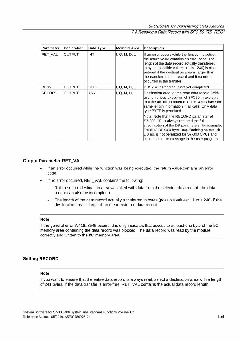
SFCs/SFBs for Transferring Data Records 7.8 Reading a Data Record with SFC 59 "RD_REC"
System Software for S7-300/400 System and Standard Functions Volume 1/2 Reference Manual, 05/2010, A5E02789976-01 159
Parameter Declaration Data Type Memory Area Description
RET_VAL OUTPUT INT I, Q, M, D, L If an error occurs while the function is active, the return value contains an error code. The length of the data record actually transferred in bytes (possible values: +1 to +240) is also entered if the destination area is larger than the transferred data record and if no error occurred in the transfer.
BUSY OUTPUT BOOL I, Q, M, D, L BUSY = 1: Reading is not yet completed. RECORD OUTPUT ANY I, Q, M, D, L Destination area for the read data record. With
asynchronous execution of SFC59, make sure that the actual parameters of RECORD have the same length information in all calls. Only data type BYTE is permitted. Note: Note that the RECORD parameter of S7-300 CPUs always required the full specification of the DB parameters (for example: P#DB13.DBX0.0 byte 100). Omitting an explicit DB no. is not permitted for S7-300 CPUs and causes an error message in the user program.
Output Parameter RET_VAL • If an error occurred while the function was being executed, the return value contains an error
code.
• If no error occurred, RET_VAL contains the following:
- 0: if the entire destination area was filled with data from the selected data record (the data record can also be incomplete).
- The length of the data record actually transferred in bytes (possible values: +1 to + 240) if the destination area is larger than the transferred data record.
Note
If the general error W#16#8545 occurs, this only indicates that access to at least one byte of the I/O memory area containing the data record was blocked. The data record was read by the module correctly and written to the I/O memory area.
Setting RECORD
Note If you want to ensure that the entire data record is always read, select a destination area with a length of 241 bytes. If the data transfer is error-free, RET_VAL contains the actual data record length.
SFCs/SFBs for Transferring Data Records 7.8 Reading a Data Record with SFC 59 "RD_REC"
System Software for S7-300/400 System and Standard Functions Volume 1/2 160 Reference Manual, 05/2010, A5E02789976-01
Using Old S7-300 FMs and CPs with Data Record Numbers > 1 If you want to read out a data record with a number higher than 1 from an old S7-300 FM or old S7-300 CP using SFC 59 "RD_REC," remember the following points:
• If the destination area is larger than the actual length of the required data record, no data are entered in RECORD. RET_VAL has the value W#16#80B1.
• If the destination area is smaller than the actual length of the required data record, the CPU reads as many bytes beginning at the start of the record as are specified in the length information of RECORD and enters this number of bytes in RECORD. RET_VAL has the value 0.
• If the length specified in RECORD is the same as the actual length of the required data record, the CPU reads the data record and enters it in RECORD. RET_VAL has the value 0.
Error Information The "real" error information (error codes W#16#8xyz) in the following table can be divided into two classes:
• Temporary errors (error codes W#16#80A2 to 80A4, 80Cx): With this type of error, it is possible that the error will be eliminated without you taking any action, in other words, it is advisable to call the SFC again (if necessary, more than once). An example of a temporary error is when required resources are currently being used (W#16#80C3).
• Permanent errors (error codes W#16#809x, 80A1, 80Bx, 80Dx): This type of error will not be eliminated without you taking action. Calling the SFC again will only be successful after the error has been eliminated. An example of a permanent error is entering the wrong length in RECORD (W#16#80B1).
Note
If you transfer data records to a DPV1 slave with SFC 58 "WR_REC" or if you fetch data records from a DPV1 slave with SFC 59 "RD_REC" and if this DPV1 slave operates in DPV1 mode, the DP Master evaluates the error information it received from the Slave as follows:
If the error information lies within the range from W#16#8000 to W#16#80FF or W#16#F000 to W#16#FFFF the DP master passes the error information to the SFC. If it lies out of this range, the CPU passes the value W#16#80A2 to the SFC and suspends the slave.
For a description of the error information received from DPV1-Slaves, see Receiving an Interrupt from a DP-Slave with SFB 54 "RALRM" STATUS[3].
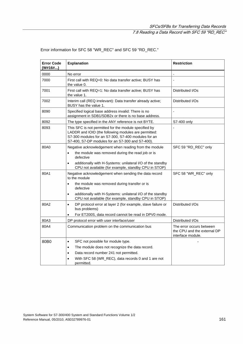
SFCs/SFBs for Transferring Data Records 7.8 Reading a Data Record with SFC 59 "RD_REC"
System Software for S7-300/400 System and Standard Functions Volume 1/2 Reference Manual, 05/2010, A5E02789976-01 161
Error information for SFC 58 "WR_REC" and SFC 59 "RD_REC."
Error Code (W#16#...)
Explanation
Restriction
0000 No error - 7000 First call with REQ=0: No data transfer active; BUSY has
the value 0. -
7001 First call with REQ=1: No data transfer active; BUSY has the value 1.
Distributed I/Os
7002 Interim call (REQ irrelevant): Data transfer already active; BUSY has the value 1.
Distributed I/Os
8090 Specified logical base address invalid: There is no assignment in SDB1/SDB2x or there is no base address.
-
8092 The type specified in the ANY reference is not BYTE. S7-400 only 8093 This SFC is not permitted for the module specified by
LADDR and IOID (the following modules are permitted: S7-300 modules for an S7-300, S7-400 modules for an S7-400, S7-DP modules for an S7-300 and S7-400).
-
80A0 Negative acknowledgement when reading from the module • the module was removed during the read job or is
defective • additionally with H-Systems: unilateral I/O of the standby
CPU not available (for example, standby CPU in STOP)
SFC 59 "RD_REC" only
80A1 Negative acknowledgement when sending the data record to the module • the module was removed during transfer or is
defective • additionally with H-Systems: unilateral I/O of the standby
CPU not available (for example, standby CPU in STOP)
SFC 58 "WR_REC" only
80A2 • DP protocol error at layer 2 (for example, slave failure or bus problems)
• For ET200S, data record cannot be read in DPV0 mode.
Distributed I/Os
80A3 DP protocol error with user interface/user Distributed I/Os 80A4 Communication problem on the communication bus The error occurs between
the CPU and the external DP interface module.
80B0 • SFC not possible for module type. • The module does not recognize the data record. • Data record number 241 not permitted. • With SFC 58 (WR_REC), data records 0 and 1 are not
permitted.
-
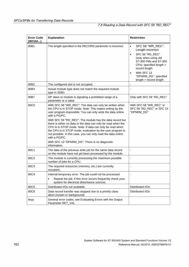
SFCs/SFBs for Transferring Data Records 7.8 Reading a Data Record with SFC 59 "RD_REC"
System Software for S7-300/400 System and Standard Functions Volume 1/2 162 Reference Manual, 05/2010, A5E02789976-01
Error Code (W#16#...)
Explanation
Restriction
80B1 The length specified in the RECORD parameter is incorrect. • SFC 58 "WR_REC": Length incorrect
• SFC 59 "RD_REC" (only when using old S7-300 FMs and S7-300 CPs): specified length > record length
• With SFC 13 "DPNRM_DG": specified length > record length
80B2 The configured slot is not occupied. - 80B3 Actual module type does not match the required module
type in SDB1 -
80B7 DP slave or module is signaling a prohibited range of a parameter or a value
Only with SFC 59 "RD_REC"
80C0 With SFC 58 "WR_REC": The data can only be written when the CPU is in STOP mode. Note: This makes writing by the user program impossible. You can only write the data online with a PG/PC. With SFC 59 "RD_REC": The module has the data record but there is either no data or the data can only be read when the CPU is in STOP mode. Note: If data can only be read when the CPU is in STOP mode, evaluation by the user program is not possible. In this case, you can only read the data online with a PG/PC. With SFC 13 "DPNRM_DG": There is no diagnostic information.
With SFC 58 "WR_REC" or SFC 59 "RD_REC" or SFC 13 "DPNRM_DG"
80C1 The data of the previous write job for the same data record on the module have not yet been processed by the module.
-
80C2 The module is currently processing the maximum possible number of jobs for a CPU.
-
80C3 The required resources (memory, etc.) are currently occupied.
-
80C4 Internal temporary error. The job could not be processed. • Repeat the job. If this error occurs frequently check your
system for electrical disturbance sources.
-
80C5 Distributed I/Os not available. Distributed I/Os 80C6 Data record transfer was stopped due to a priority class
abort (restart or background) Distributed I/Os
8xyy General error codes, see Evaluating Errors with the Output Parameter RET_VAL
SFCs/SFBs for Transferring Data Records 7.9 Further Error Information for SFCs 55 to 59
System Software for S7-300/400 System and Standard Functions Volume 1/2 Reference Manual, 05/2010, A5E02789976-01 163
7.9 Further Error Information for SFCs 55 to 59
S7-400 only With the S7-400, the SFCs 55 to 59 can also return the error information W#16#80Fx. In this case an error occurred that could not be localized. Please contact the maintenance department in this case.
7.10 Reading Predefined Parameters with SFB 81 "RD_DPAR"
Description SFB 81 "RD_DPAR" (read device parameter) lets you read the data record with the INDEX number of the component addressed from the system data configured with STEP 7. This can be a centrally inserted module or a distributed component (PROFIBUS DP or PROFINET IO).
The value TRUE for the VALID output parameter indicates that the data record was successfully transferred to the RECORD destination area. In this case, the LEN output parameter contains the length of the read data in bytes.
If an error occurred during transfer of the data record, this is indicated by the output parameter ERROR. In this case, the output parameter STATUS contains the error information.
Function The SFB 81 "RD_DPAR" operates asynchronously; that is, the processing extends over several SFB calls. To start the data transfer, call SFB 81 with REQ = 1.
The output parameter BUSY and bytes 2 and 3 of the output parameter STATUS show the status of the job. Bytes 2 and 3 of STATUS correspond to the output parameter RET_VAL of asynchronously operating SFCs (see also Meaning of REQ, RET_VAL and BUSY for asynchronously operating SFCs
The transfer of the data record is complete when the output parameter BUSY has the value FALSE.
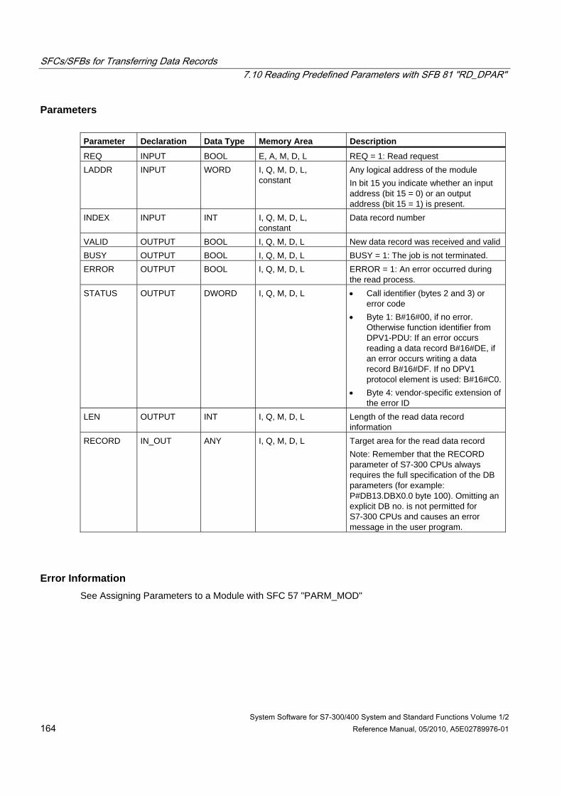
SFCs/SFBs for Transferring Data Records 7.10 Reading Predefined Parameters with SFB 81 "RD_DPAR"
System Software for S7-300/400 System and Standard Functions Volume 1/2 164 Reference Manual, 05/2010, A5E02789976-01
Parameters Parameter Declaration Data Type Memory Area Description
REQ INPUT BOOL E, A, M, D, L REQ = 1: Read request LADDR INPUT WORD I, Q, M, D, L,
constant Any logical address of the module In bit 15 you indicate whether an input address (bit 15 = 0) or an output address (bit 15 = 1) is present.
INDEX INPUT INT I, Q, M, D, L, constant
Data record number
VALID OUTPUT BOOL I, Q, M, D, L New data record was received and valid BUSY OUTPUT BOOL I, Q, M, D, L BUSY = 1: The job is not terminated. ERROR OUTPUT BOOL I, Q, M, D, L ERROR = 1: An error occurred during
the read process. STATUS OUTPUT DWORD I, Q, M, D, L • Call identifier (bytes 2 and 3) or
error code • Byte 1: B#16#00, if no error.
Otherwise function identifier from DPV1-PDU: If an error occurs reading a data record B#16#DE, if an error occurs writing a data record B#16#DF. If no DPV1 protocol element is used: B#16#C0.
• Byte 4: vendor-specific extension of the error ID
LEN OUTPUT INT I, Q, M, D, L Length of the read data record information
RECORD IN_OUT ANY I, Q, M, D, L Target area for the read data record Note: Remember that the RECORD parameter of S7-300 CPUs always requires the full specification of the DB parameters (for example: P#DB13.DBX0.0 byte 100). Omitting an explicit DB no. is not permitted for S7-300 CPUs and causes an error message in the user program.
Error Information See Assigning Parameters to a Module with SFC 57 "PARM_MOD"
System Software for S7-300/400 System and Standard Functions Volume 1/2 Reference Manual, 05/2010, A5E02789976-01 165
8 DPV1 SFBs According to PNO AK 1131
8.1 Reading a Data Record with SFB 52 "RDREC" Note
The SFB52 "RDREC" interface is identical to the FB "RDREC" defined in the standard "PROFIBUS Guideline PROFIBUS Communication and Proxy Function Blocks according to IEC 61131-3".
Description With the SFB52 "RDREC" (read record) you read a data record with the number INDEX from a component. This may be a module in a central rack or a distributed component (PROFIBUS DP or PROFINET IO).
Specify the maximum number of bytes you want to read in MLEN. The selected length of the target area RECORD should have at least the length of MLEN bytes.
TRUE on output parameter VALID verifies that the data record has been successfully transferred into the target area RECORD. In this case, the output parameter LEN contains the length of the fetched data in bytes.
The output parameter ERROR indicates whether a data record transmission error has occurred. In this case, the output parameter STATUS contains the error information.
Note
If a DPV1 slave is configured using a GSD file (GSD as of Rev. 3) and the DP interface of the DP master is set to "S7 compatible", then data records must not be read from I/O modules in the user program with SFC 52. The reason is that in this case the DP master addresses the incorrect slot (configured slot +3). Remedy: Set the interface for the DP master to "DPV1".
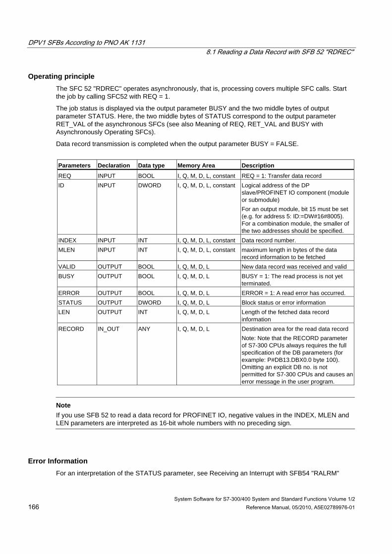
DPV1 SFBs According to PNO AK 1131 8.1 Reading a Data Record with SFB 52 "RDREC"
System Software for S7-300/400 System and Standard Functions Volume 1/2 166 Reference Manual, 05/2010, A5E02789976-01
Operating principle The SFC 52 "RDREC" operates asynchronously, that is, processing covers multiple SFC calls. Start the job by calling SFC52 with REQ = 1.
The job status is displayed via the output parameter BUSY and the two middle bytes of output parameter STATUS. Here, the two middle bytes of STATUS correspond to the output parameter RET_VAL of the asynchronous SFCs (see also Meaning of REQ, RET_VAL and BUSY with Asynchronously Operating SFCs).
Data record transmission is completed when the output parameter BUSY = FALSE.
Parameters Declaration Data type Memory Area Description
REQ INPUT BOOL I, Q, M, D, L, constant REQ = 1: Transfer data record ID INPUT DWORD I, Q, M, D, L, constant Logical address of the DP
slave/PROFINET IO component (module or submodule) For an output module, bit 15 must be set (e.g. for address 5: ID:=DW#16#8005). For a combination module, the smaller of the two addresses should be specified.
INDEX INPUT INT I, Q, M, D, L, constant Data record number. MLEN INPUT INT I, Q, M, D, L, constant maximum length in bytes of the data
record information to be fetched VALID OUTPUT BOOL I, Q, M, D, L New data record was received and valid BUSY OUTPUT BOOL I, Q, M, D, L BUSY = 1: The read process is not yet
terminated. ERROR OUTPUT BOOL I, Q, M, D, L ERROR = 1: A read error has occurred. STATUS OUTPUT DWORD I, Q, M, D, L Block status or error information LEN OUTPUT INT I, Q, M, D, L Length of the fetched data record
information RECORD IN_OUT ANY I, Q, M, D, L Destination area for the read data record
Note: Note that the RECORD parameter of S7-300 CPUs always requires the full specification of the DB parameters (for example: P#DB13.DBX0.0 byte 100). Omitting an explicit DB no. is not permitted for S7-300 CPUs and causes an error message in the user program.
Note
If you use SFB 52 to read a data record for PROFINET IO, negative values in the INDEX, MLEN and LEN parameters are interpreted as 16-bit whole numbers with no preceding sign.
Error Information For an interpretation of the STATUS parameter, see Receiving an Interrupt with SFB54 "RALRM"
DPV1 SFBs According to PNO AK 1131 8.2 Writing a Data Record with SFB53 "WRREC"
System Software for S7-300/400 System and Standard Functions Volume 1/2 Reference Manual, 05/2010, A5E02789976-01 167
8.2 Writing a Data Record with SFB53 "WRREC" Note
The SFB52 "WRREC" interface is identical to the FB "WRREC" defined in the standard "PROFIBUS Guideline PROFIBUS Communication and Proxy Function Blocks according to IEC 61131-3"
Description With the SFB52 "WRREC" (write record) you transfer a data record with the number INDEX to a DP slave/PROFINET IO device component defined by ID. This might be a module in the central rack or a distribute component (PROFIBUS DP or PROFINET IO).
Specify the byte length of the data record to be transmitted. The selected length of the source area RECORD should, therefore, have at least the length of LEN bytes.
TRUE on output parameter DONE verifies that the data record has been successfully transferred to the DP Slave.
The output parameter ERROR indicates whether a data record transmission error has occurred. In this case, the output parameter STATUS contains the error information.
Note
If a DPV1 slave is configured using a GSD file (GSD as of Rev. 3) and the DP interface of the DP master is set to "S7 compatible", then data records must not be written to I/O modules in the user program with SFC 53. The reason is that in this case the DP master addresses the incorrect slot (configured slot +3). Remedy: Set the interface for the DP master to "DPV1".
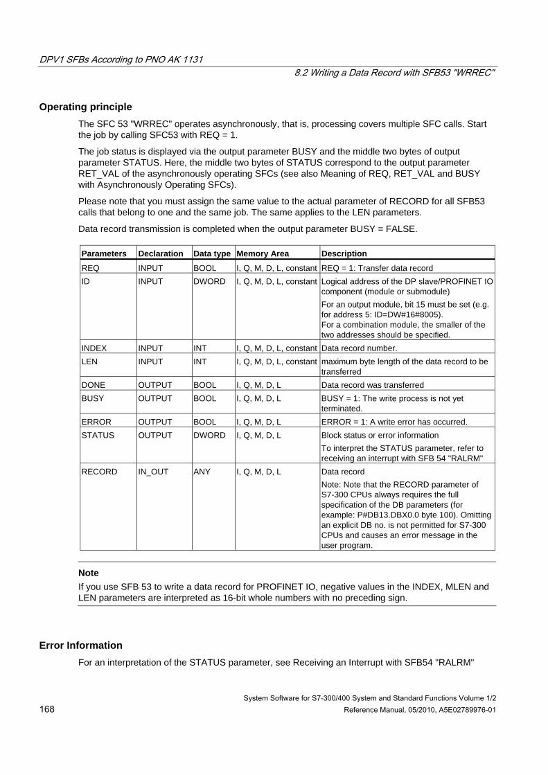
DPV1 SFBs According to PNO AK 1131 8.2 Writing a Data Record with SFB53 "WRREC"
System Software for S7-300/400 System and Standard Functions Volume 1/2 168 Reference Manual, 05/2010, A5E02789976-01
Operating principle The SFC 53 "WRREC" operates asynchronously, that is, processing covers multiple SFC calls. Start the job by calling SFC53 with REQ = 1.
The job status is displayed via the output parameter BUSY and the middle two bytes of output parameter STATUS. Here, the middle two bytes of STATUS correspond to the output parameter RET_VAL of the asynchronously operating SFCs (see also Meaning of REQ, RET_VAL and BUSY with Asynchronously Operating SFCs).
Please note that you must assign the same value to the actual parameter of RECORD for all SFB53 calls that belong to one and the same job. The same applies to the LEN parameters.
Data record transmission is completed when the output parameter BUSY = FALSE. Parameters Declaration Data type Memory Area Description
REQ INPUT BOOL I, Q, M, D, L, constant REQ = 1: Transfer data record ID INPUT DWORD I, Q, M, D, L, constant Logical address of the DP slave/PROFINET IO
component (module or submodule) For an output module, bit 15 must be set (e.g. for address 5: ID=DW#16#8005). For a combination module, the smaller of the two addresses should be specified.
INDEX INPUT INT I, Q, M, D, L, constant Data record number. LEN INPUT INT I, Q, M, D, L, constant maximum byte length of the data record to be
transferred DONE OUTPUT BOOL I, Q, M, D, L Data record was transferred BUSY OUTPUT BOOL I, Q, M, D, L BUSY = 1: The write process is not yet
terminated. ERROR OUTPUT BOOL I, Q, M, D, L ERROR = 1: A write error has occurred. STATUS OUTPUT DWORD I, Q, M, D, L Block status or error information
To interpret the STATUS parameter, refer to receiving an interrupt with SFB 54 "RALRM"
RECORD IN_OUT ANY I, Q, M, D, L Data record Note: Note that the RECORD parameter of S7-300 CPUs always requires the full specification of the DB parameters (for example: P#DB13.DBX0.0 byte 100). Omitting an explicit DB no. is not permitted for S7-300 CPUs and causes an error message in the user program.
Note
If you use SFB 53 to write a data record for PROFINET IO, negative values in the INDEX, MLEN and LEN parameters are interpreted as 16-bit whole numbers with no preceding sign.
Error Information For an interpretation of the STATUS parameter, see Receiving an Interrupt with SFB54 "RALRM"
DPV1 SFBs According to PNO AK 1131 8.3 Receiving an Interrupt with SFB 54 "RALRM"
System Software for S7-300/400 System and Standard Functions Volume 1/2 Reference Manual, 05/2010, A5E02789976-01 169
8.3 Receiving an Interrupt with SFB 54 "RALRM"
Note
The SFB52 "RALRM" interface is identical to the FB "RALRM" defined in the standard "PROFIBUS Guideline PROFIBUS Communication and Proxy Function Blocks according to IEC 61131-3"
Description The SFB "RALRM" receives an interrupt with all corresponding information from an I/O module (centralized structure) or from a DP slave or PROFINET IO device component. It supplies this information to its output parameters.
The information in the output parameters contains the start information of the called OB as well as information on the interrupt source.
Call the SFB54 only within the interrupt OB started by the CPU operating system in order to examine the I/O interrupt.
Note
If you call SFB54 "RALRM" in an OB for which the start event was not triggered by I/Os, the SFB supplies correspondingly reduced information on its outputs. Make sure to use different instance DBs when you call SFB 54 "RALRM" in different OBs. If you want to evaluate data that are the result of an SFB54 call outside of the associated interrupt OB you should moreover use a separate instance DB per OB start event.
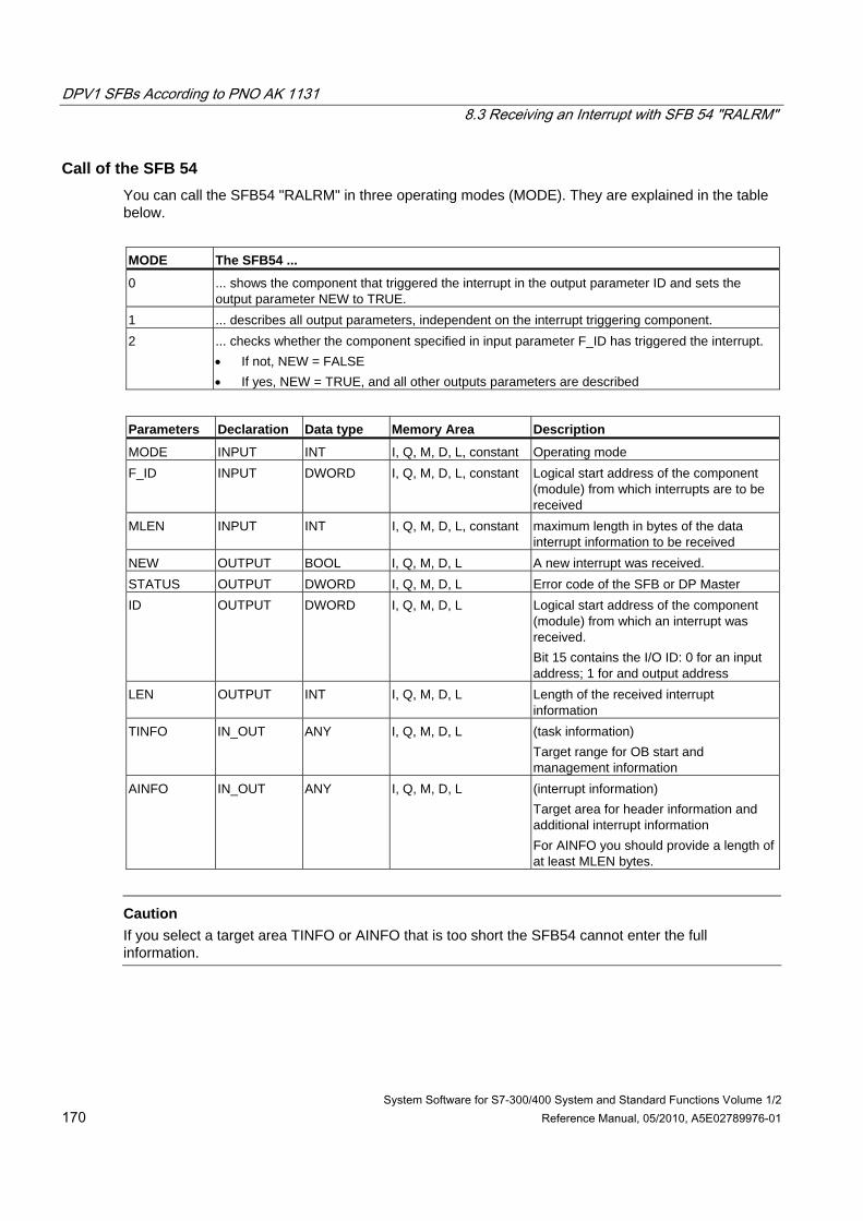
DPV1 SFBs According to PNO AK 1131 8.3 Receiving an Interrupt with SFB 54 "RALRM"
System Software for S7-300/400 System and Standard Functions Volume 1/2 170 Reference Manual, 05/2010, A5E02789976-01
Call of the SFB 54 You can call the SFB54 "RALRM" in three operating modes (MODE). They are explained in the table below.
MODE The SFB54 ...
0 ... shows the component that triggered the interrupt in the output parameter ID and sets the output parameter NEW to TRUE.
1 ... describes all output parameters, independent on the interrupt triggering component. 2 ... checks whether the component specified in input parameter F_ID has triggered the interrupt.
• If not, NEW = FALSE • If yes, NEW = TRUE, and all other outputs parameters are described
Parameters Declaration Data type Memory Area Description
MODE INPUT INT I, Q, M, D, L, constant Operating mode F_ID INPUT DWORD I, Q, M, D, L, constant Logical start address of the component
(module) from which interrupts are to be received
MLEN INPUT INT I, Q, M, D, L, constant maximum length in bytes of the data interrupt information to be received
NEW OUTPUT BOOL I, Q, M, D, L A new interrupt was received. STATUS OUTPUT DWORD I, Q, M, D, L Error code of the SFB or DP Master ID OUTPUT DWORD I, Q, M, D, L Logical start address of the component
(module) from which an interrupt was received. Bit 15 contains the I/O ID: 0 for an input address; 1 for and output address
LEN OUTPUT INT I, Q, M, D, L Length of the received interrupt information
TINFO IN_OUT ANY I, Q, M, D, L (task information) Target range for OB start and management information
AINFO IN_OUT ANY I, Q, M, D, L (interrupt information) Target area for header information and additional interrupt information For AINFO you should provide a length of at least MLEN bytes.
Caution
If you select a target area TINFO or AINFO that is too short the SFB54 cannot enter the full information.
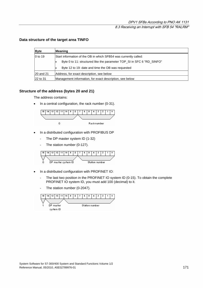
DPV1 SFBs According to PNO AK 1131 8.3 Receiving an Interrupt with SFB 54 "RALRM"
System Software for S7-300/400 System and Standard Functions Volume 1/2 Reference Manual, 05/2010, A5E02789976-01 171
Data structure of the target area TINFO Byte Meaning
0 to 19 Start information of the OB in which SFB54 was currently called:
• Byte 0 to 11: structured like the parameter TOP_SI in SFC 6 "RD_SINFO"
• Byte 12 to 19: date and time the OB was requested
20 and 21 Address, for exact description, see below 22 to 31 Management information, for exact description, see below
Structure of the address (bytes 20 and 21) The address contains:
• In a central configuration, the rack number (0-31).
• In a distributed configuration with PROFIBUS DP
- The DP master system ID (1-32)
- The station number (0-127).
• In a distributed configuration with PROFINET IO:
- The last two position in the PROFINET IO system ID (0-15). To obtain the complete PROFINET IO system ID, you must add 100 (decimal) to it.
- The station number (0-2047).
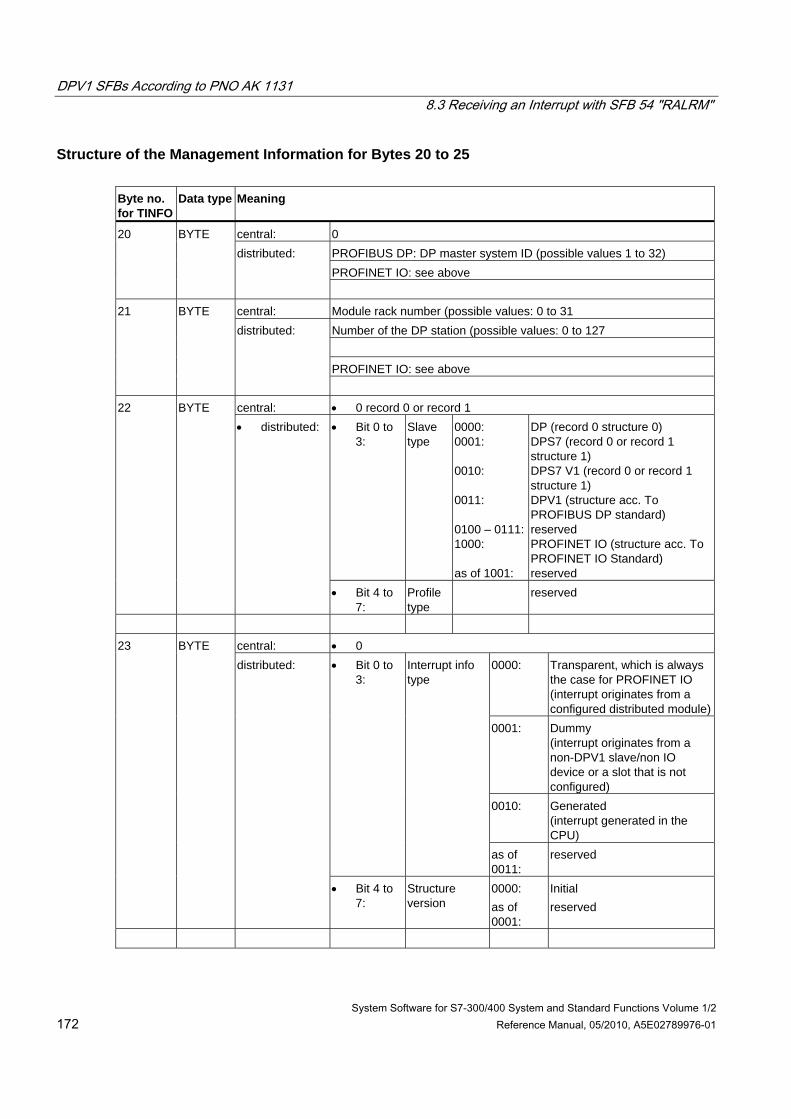
DPV1 SFBs According to PNO AK 1131 8.3 Receiving an Interrupt with SFB 54 "RALRM"
System Software for S7-300/400 System and Standard Functions Volume 1/2 172 Reference Manual, 05/2010, A5E02789976-01
Structure of the Management Information for Bytes 20 to 25 Byte no. for TINFO
Data type Meaning
central: 0 PROFIBUS DP: DP master system ID (possible values 1 to 32) PROFINET IO: see above
20 BYTE distributed:
central: Module rack number (possible values: 0 to 31
Number of the DP station (possible values: 0 to 127 PROFINET IO: see above
21 BYTE distributed:
central: • 0 record 0 or record 1
• Bit 0 to 3:
Slave type
0000: 0001: 0010: 0011: 0100 – 0111:1000: as of 1001:
DP (record 0 structure 0) DPS7 (record 0 or record 1 structure 1) DPS7 V1 (record 0 or record 1 structure 1) DPV1 (structure acc. To PROFIBUS DP standard) reserved PROFINET IO (structure acc. To PROFINET IO Standard) reserved
22 BYTE • distributed:
• Bit 4 to 7:
Profile type
reserved
central: • 0
0000: Transparent, which is always the case for PROFINET IO (interrupt originates from a configured distributed module)
0001: Dummy (interrupt originates from a non-DPV1 slave/non IO device or a slot that is not configured)
0010: Generated (interrupt generated in the CPU)
• Bit 0 to 3:
Interrupt info type
as of 0011:
reserved
23 BYTE distributed:
• Bit 4 to 7:
Structure version
0000: as of 0001:
Initial reserved
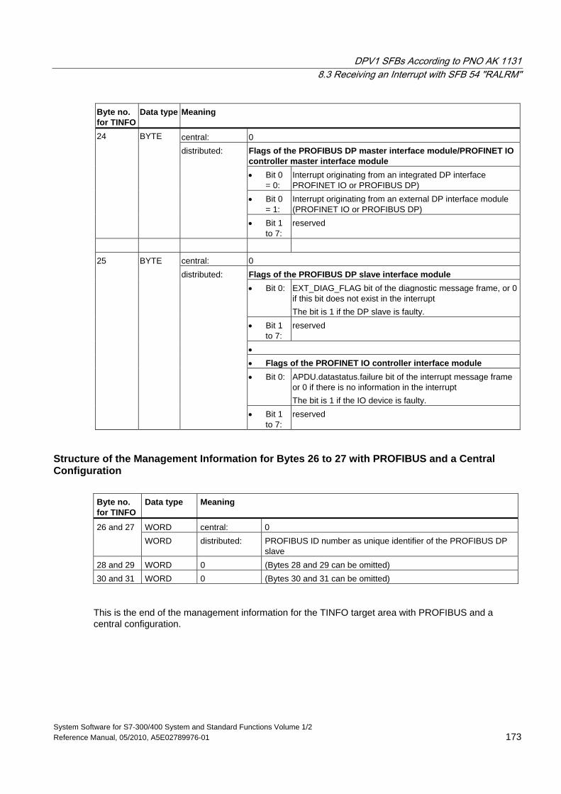
DPV1 SFBs According to PNO AK 1131 8.3 Receiving an Interrupt with SFB 54 "RALRM"
System Software for S7-300/400 System and Standard Functions Volume 1/2 Reference Manual, 05/2010, A5E02789976-01 173
Byte no. for TINFO
Data type Meaning
central: 0 Flags of the PROFIBUS DP master interface module/PROFINET IO controller master interface module • Bit 0
= 0: Interrupt originating from an integrated DP interface PROFINET IO or PROFIBUS DP)
• Bit 0 = 1:
Interrupt originating from an external DP interface module (PROFINET IO or PROFIBUS DP)
24 BYTE
distributed:
• Bit 1 to 7:
reserved
central: 0
Flags of the PROFIBUS DP slave interface module • Bit 0: EXT_DIAG_FLAG bit of the diagnostic message frame, or 0
if this bit does not exist in the interrupt The bit is 1 if the DP slave is faulty.
• Bit 1 to 7:
reserved
• • Flags of the PROFINET IO controller interface module • Bit 0: APDU.datastatus.failure bit of the interrupt message frame
or 0 if there is no information in the interrupt The bit is 1 if the IO device is faulty.
25 BYTE distributed:
• Bit 1 to 7:
reserved
Structure of the Management Information for Bytes 26 to 27 with PROFIBUS and a Central Configuration
Byte no. for TINFO
Data type Meaning
WORD central: 0 26 and 27 WORD distributed: PROFIBUS ID number as unique identifier of the PROFIBUS DP
slave 28 and 29 WORD 0 (Bytes 28 and 29 can be omitted) 30 and 31 WORD 0 (Bytes 30 and 31 can be omitted)
This is the end of the management information for the TINFO target area with PROFIBUS and a central configuration.
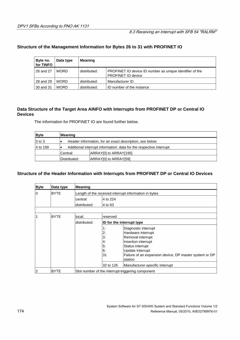
DPV1 SFBs According to PNO AK 1131 8.3 Receiving an Interrupt with SFB 54 "RALRM"
System Software for S7-300/400 System and Standard Functions Volume 1/2 174 Reference Manual, 05/2010, A5E02789976-01
Structure of the Management Information for Bytes 26 to 31 with PROFINET IO Byte no. for TINFO
Data type Meaning
26 and 27 WORD distributed: PROFINET IO device ID number as unique identifier of the PROFINET IO device
28 and 29 WORD distributed: Manufacturer ID 30 and 31 WORD distributed: ID number of the instance
Data Structure of the Target Area AINFO with Interrupts from PROFINET DP or Central IO Devices
The information for PROFINET IO are found further below.
Byte Meaning
0 to 3 • Header information, for an exact description, see below 4 to 199 • Additional interrupt information: data for the respective interrupt: Central: ARRAY[0] to ARRAY[195] Distributed: ARRAY[0] to ARRAY[59]
Structure of the Header Information with Interrupts from PROFINET DP or Central IO Devices Byte Data type Meaning
Length of the received interrupt information in bytes 0 BYTE central: distributed:
4 to 224 4 to 63
local: reserved
ID for the interrupt type 1: 2: 3: 4: 5: 6: 31
Diagnostic interrupt Hardware interrupt Removal interrupt Insertion interrupt Status interrupt Update Interrupt Failure of an expansion device, DP master system or DP station
1 BYTE distributed:
32 to 126 Manufacturer-specific interrupt 2 BYTE Slot number of the interrupt-triggering component
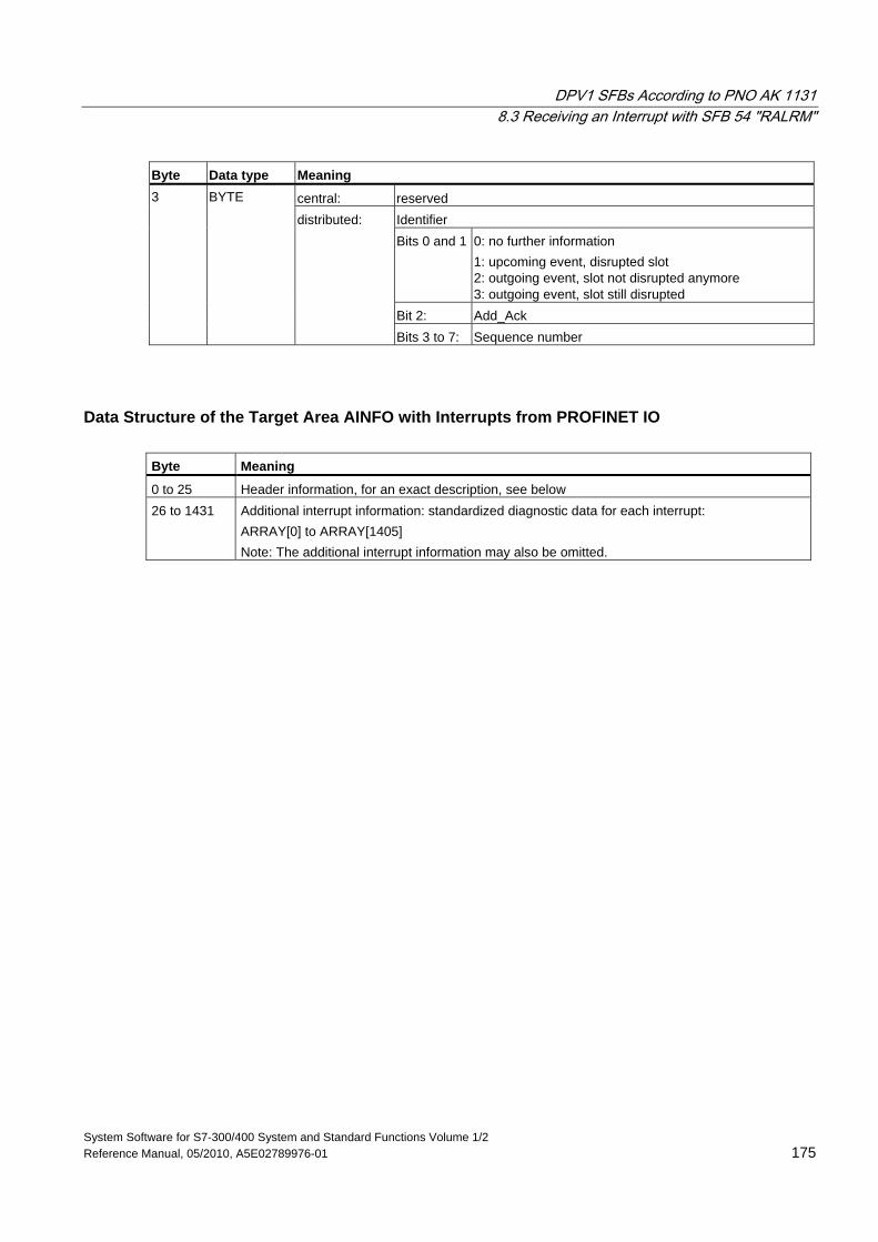
DPV1 SFBs According to PNO AK 1131 8.3 Receiving an Interrupt with SFB 54 "RALRM"
System Software for S7-300/400 System and Standard Functions Volume 1/2 Reference Manual, 05/2010, A5E02789976-01 175
Byte Data type Meaning
central: reserved Identifier Bits 0 and 1 0: no further information
1: upcoming event, disrupted slot 2: outgoing event, slot not disrupted anymore 3: outgoing event, slot still disrupted
Bit 2: Add_Ack
3 BYTE
distributed:
Bits 3 to 7: Sequence number
Data Structure of the Target Area AINFO with Interrupts from PROFINET IO Byte Meaning
0 to 25 Header information, for an exact description, see below 26 to 1431 Additional interrupt information: standardized diagnostic data for each interrupt:
ARRAY[0] to ARRAY[1405] Note: The additional interrupt information may also be omitted.
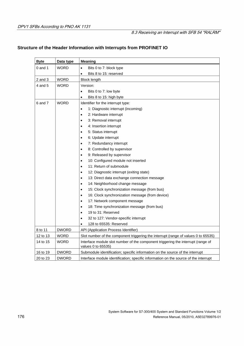
DPV1 SFBs According to PNO AK 1131 8.3 Receiving an Interrupt with SFB 54 "RALRM"
System Software for S7-300/400 System and Standard Functions Volume 1/2 176 Reference Manual, 05/2010, A5E02789976-01
Structure of the Header Information with Interrupts from PROFINET IO Byte Data type Meaning
0 and 1 WORD • Bits 0 to 7: block type • Bits 8 to 15: reserved
2 and 3 WORD Block length 4 and 5 WORD Version:
• Bits 0 to 7: low byte • Bits 8 to 15: high byte
6 and 7 WORD Identifier for the interrupt type: • 1: Diagnostic interrupt (incoming) • 2: Hardware interrupt • 3: Removal interrupt • 4: Insertion interrupt • 5: Status interrupt • 6: Update interrupt • 7: Redundancy interrupt • 8: Controlled by supervisor • 9: Released by supervisor • 10: Configured module not inserted • 11: Return of submodule • 12: Diagnostic interrupt (exiting state) • 13: Direct data exchange connection message • 14: Neighborhood change message • 15: Clock synchronization message (from bus) • 16: Clock synchronization message (from device) • 17: Network component message • 18: Time synchronization message (from bus) • 19 to 31: Reserved • 32 to 127: Vendor-specific interrupt • 128 to 65535: Reserved
8 to 11 DWORD API (Application Process Identifier) 12 to 13 WORD Slot number of the component triggering the interrupt (range of values 0 to 65535) 14 to 15 WORD Interface module slot number of the component triggering the interrupt (range of
values 0 to 65535) 16 to 19 DWORD Submodule identification; specific information on the source of the interrupt 20 to 23 DWORD Interface module identification; specific information on the source of the interrupt
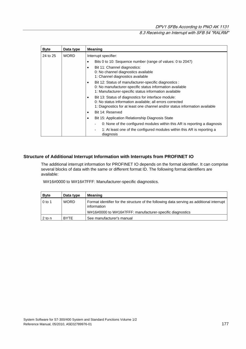
DPV1 SFBs According to PNO AK 1131 8.3 Receiving an Interrupt with SFB 54 "RALRM"
System Software for S7-300/400 System and Standard Functions Volume 1/2 Reference Manual, 05/2010, A5E02789976-01 177
Byte Data type Meaning
24 to 25 WORD Interrupt specifier: • Bits 0 to 10: Sequence number (range of values: 0 to 2047) • Bit 11: Channel diagnostics:
0: No channel diagnostics available 1: Channel diagnostics available
• Bit 12: Status of manufacturer-specific diagnostics : 0: No manufacturer-specific status information available 1: Manufacturer-specific status information available
• Bit 13: Status of diagnostics for interface module: 0: No status information available; all errors corrected 1: Diagnostics for at least one channel and/or status information available
• Bit 14: Reserved • Bit 15: Application Relationship Diagnosis State
- 0: None of the configured modules within this AR is reporting a diagnosis - 1: At least one of the configured modules within this AR is reporting a
diagnosis
Structure of Additional Interrupt Information with Interrupts from PROFINET IO The additional interrupt information for PROFINET IO depends on the format identifier. It can comprise several blocks of data with the same or different format ID. The following format identifiers are available:
W#16#0000 to W#16#7FFF: Manufacturer-specific diagnostics.
Byte Data type Meaning
0 to 1 WORD Format identifier for the structure of the following data serving as additional interrupt information W#16#0000 to W#16#7FFF: manufacturer-specific diagnostics
2 to n BYTE See manufacturer's manual
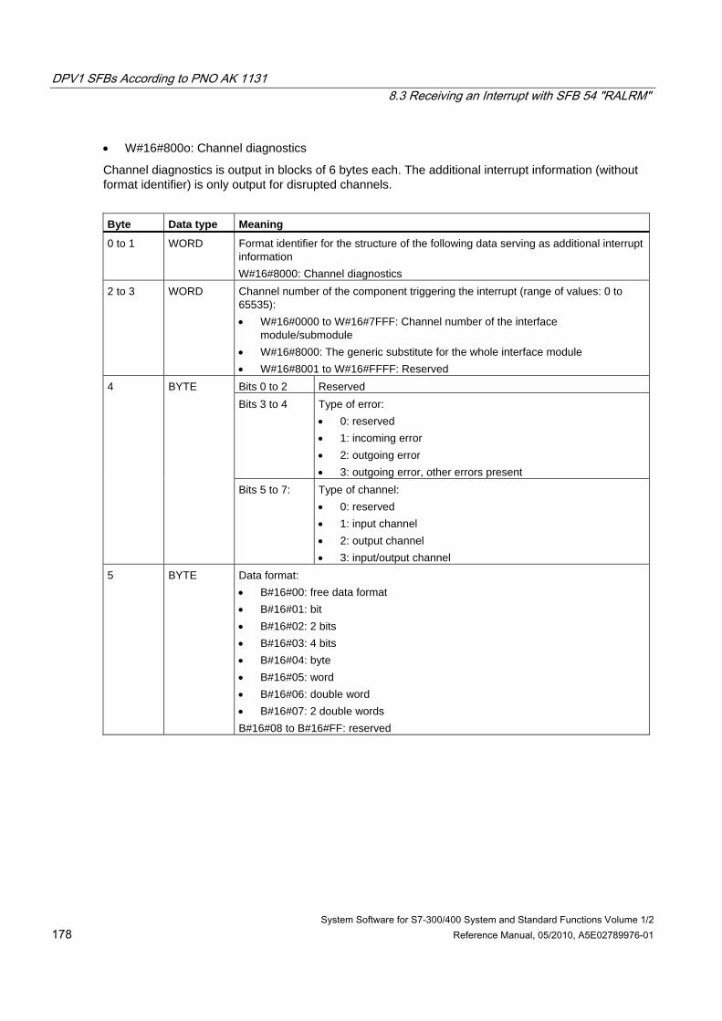
DPV1 SFBs According to PNO AK 1131 8.3 Receiving an Interrupt with SFB 54 "RALRM"
System Software for S7-300/400 System and Standard Functions Volume 1/2 178 Reference Manual, 05/2010, A5E02789976-01
• W#16#800o: Channel diagnostics
Channel diagnostics is output in blocks of 6 bytes each. The additional interrupt information (without format identifier) is only output for disrupted channels.
Byte Data type Meaning
0 to 1 WORD Format identifier for the structure of the following data serving as additional interrupt information W#16#8000: Channel diagnostics
2 to 3 WORD Channel number of the component triggering the interrupt (range of values: 0 to 65535): • W#16#0000 to W#16#7FFF: Channel number of the interface
module/submodule • W#16#8000: The generic substitute for the whole interface module • W#16#8001 to W#16#FFFF: Reserved Bits 0 to 2 Reserved Bits 3 to 4 Type of error:
• 0: reserved • 1: incoming error • 2: outgoing error • 3: outgoing error, other errors present
4 BYTE
Bits 5 to 7: Type of channel: • 0: reserved • 1: input channel • 2: output channel • 3: input/output channel
5 BYTE Data format: • B#16#00: free data format • B#16#01: bit • B#16#02: 2 bits • B#16#03: 4 bits • B#16#04: byte • B#16#05: word • B#16#06: double word • B#16#07: 2 double words B#16#08 to B#16#FF: reserved
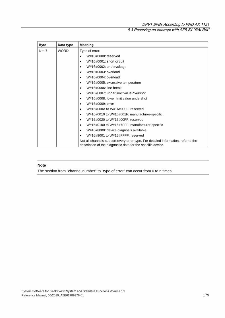
DPV1 SFBs According to PNO AK 1131 8.3 Receiving an Interrupt with SFB 54 "RALRM"
System Software for S7-300/400 System and Standard Functions Volume 1/2 Reference Manual, 05/2010, A5E02789976-01 179
Byte Data type Meaning
6 to 7 WORD Type of error: • W#16#0000: reserved • W#16#0001: short circuit • W#16#0002: undervoltage • W#16#0003: overload • W#16#0004: overload • W#16#0005: excessive temperature • W#16#0006: line break • W#16#0007: upper limit value overshot • W#16#0008: lower limit value undershot • W#16#0009: error • W#16#000A to W#16#000F: reserved • W#16#0010 to W#16#001F: manufacturer-specific • W#16#0020 to W#16#00FF: reserved • W#16#0100 to W#16#7FFF: manufacturer-specific • W#16#8000: device diagnosis available • W#16#8001 to W#16#FFFF: reserved Not all channels support every error type. For detailed information, refer to the description of the diagnostic data for the specific device.
Note
The section from "channel number" to "type of error" can occur from 0 to n times.
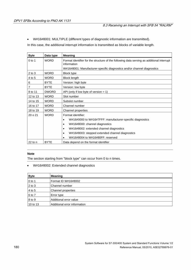
DPV1 SFBs According to PNO AK 1131 8.3 Receiving an Interrupt with SFB 54 "RALRM"
System Software for S7-300/400 System and Standard Functions Volume 1/2 180 Reference Manual, 05/2010, A5E02789976-01
• W#16#8001: MULTIPLE (different types of diagnostic information are transmitted).
In this case, the additional interrupt information is transmitted as blocks of variable length.
Byte Data type Meaning
0 to 1 WORD Format identifier for the structure of the following data serving as additional interrupt information W#16#8001: Manufacturer-specific diagnostics and/or channel diagnostics
2 to 3 WORD Block type 4 to 5 WORD Block length 6 BYTE Version: high byte 7 BYTE Version: low byte 8 to 11 DWORD API (only if low byte of version = 1) 12 to 13 WORD Slot number 14 to 15 WORD Subslot number 16 to 17 WORD Channel number 18 to 19 WORD Channel properties 20 o 21 WORD Format identifier:
• W#16#0000 to W#16#7FFF: manufacturer-specific diagnostics • W#16#8000: channel diagnostics • W#16#8002: extended channel diagnostics • W#16#8003: stepped extended channel diagnostics • W#16#8004 to W#16#80FF: reserved
22 to n BYTE Data depend on the format identifier
Note
The section starting from "block type" can occur from 0 to n times.
• W#16#8002: Extended channel diagnostics
Byte Meaning
0 to 1 Format ID W#16#8002 2 to 3 Channel number 4 to 5 Channel properties 6 to 7 Error type 8 to 9 Additional error value 10 to 13 Additional error information
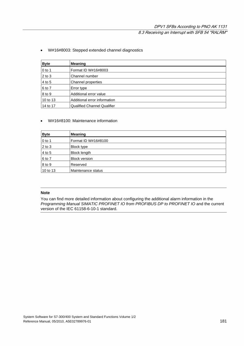
DPV1 SFBs According to PNO AK 1131 8.3 Receiving an Interrupt with SFB 54 "RALRM"
System Software for S7-300/400 System and Standard Functions Volume 1/2 Reference Manual, 05/2010, A5E02789976-01 181
• W#16#8003: Stepped extended channel diagnostics
Byte Meaning
0 to 1 Format ID W#16#8003 2 to 3 Channel number 4 to 5 Channel properties 6 to 7 Error type 8 to 9 Additional error value 10 to 13 Additional error information 14 to 17 Qualified Channel Qualifier
• W#16#8100: Maintenance information
Byte Meaning
0 to 1 Format ID W#16#8100 2 to 3 Block type 4 to 5 Block length 6 to 7 Block version 8 to 9 Reserved 10 to 13 Maintenance status
Note
You can find more detailed information about configuring the additional alarm information in the Programming Manual SIMATIC PROFINET IO from PROFIBUS DP to PROFINET IO and the current version of the IEC 61158-6-10-1 standard.
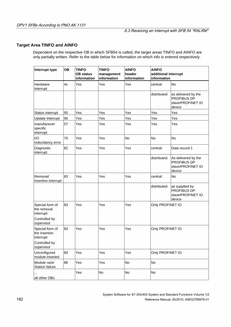
DPV1 SFBs According to PNO AK 1131 8.3 Receiving an Interrupt with SFB 54 "RALRM"
System Software for S7-300/400 System and Standard Functions Volume 1/2 182 Reference Manual, 05/2010, A5E02789976-01
Target Area TINFO and AINFO Dependent on the respective OB in which SFB54 is called, the target areas TINFO and AINFO are only partially written. Refer to the table below for information on which info is entered respectively.
Interrupt type OB TINFO
OB status information
TINFO management information
AINFO header information
AINFO additional interrupt information
Hardware interrupt
4x Yes Yes Yes central: No
distributed: as delivered by the PROFIBUS DP slave/PROFINET IO device
Status interrupt 55 Yes Yes Yes Yes Yes Update Interrupt 56 Yes Yes Yes Yes Yes manufacturer specific interrupt
57 Yes Yes Yes Yes Yes
I/O redundancy error
70 Yes Yes No No No
Diagnostic interrupt
82 Yes Yes Yes central: Data record 1
distributed: As delivered by the PROFIBUS DP slave/PROFINET IO device
Removal/ Insertion interrupt
83 Yes Yes Yes central: No
distributed: as supplied by PROFIBUS DP slave/PROFINET IO device
Special form of the removal interrupt: Controlled by supervisor
83 Yes Yes Yes Only PROFINET IO
Special form of the insertion interrupt: Controlled by supervisor
83 Yes Yes Yes Only PROFINET IO
Unconfigured module inserted
83 Yes Yes Yes Only PROFINET IO
Module rack/ Station failure
86 Yes Yes No No
... all other OBs
Yes No No No
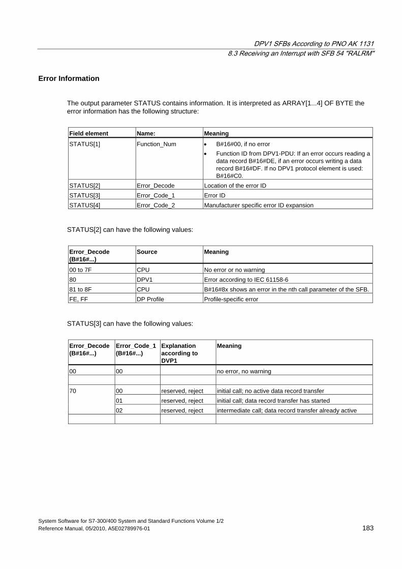
DPV1 SFBs According to PNO AK 1131 8.3 Receiving an Interrupt with SFB 54 "RALRM"
System Software for S7-300/400 System and Standard Functions Volume 1/2 Reference Manual, 05/2010, A5E02789976-01 183
Error Information
The output parameter STATUS contains information. It is interpreted as ARRAY[1...4] OF BYTE the error information has the following structure:
Field element Name: Meaning
STATUS[1] Function_Num • B#16#00, if no error • Function ID from DPV1-PDU: If an error occurs reading a
data record B#16#DE, if an error occurs writing a data record B#16#DF. If no DPV1 protocol element is used: B#16#C0.
STATUS[2] Error_Decode Location of the error ID STATUS[3] Error_Code_1 Error ID STATUS[4] Error_Code_2 Manufacturer specific error ID expansion
STATUS[2] can have the following values:
Error_Decode (B#16#...)
Source Meaning
00 to 7F CPU No error or no warning 80 DPV1 Error according to IEC 61158-6 81 to 8F CPU B#16#8x shows an error in the nth call parameter of the SFB. FE, FF DP Profile Profile-specific error
STATUS[3] can have the following values:
Error_Decode (B#16#...)
Error_Code_1 (B#16#...)
Explanation according to DVP1
Meaning
00 00 no error, no warning
00 reserved, reject initial call; no active data record transfer 01 reserved, reject initial call; data record transfer has started
70
02 reserved, reject intermediate call; data record transfer already active
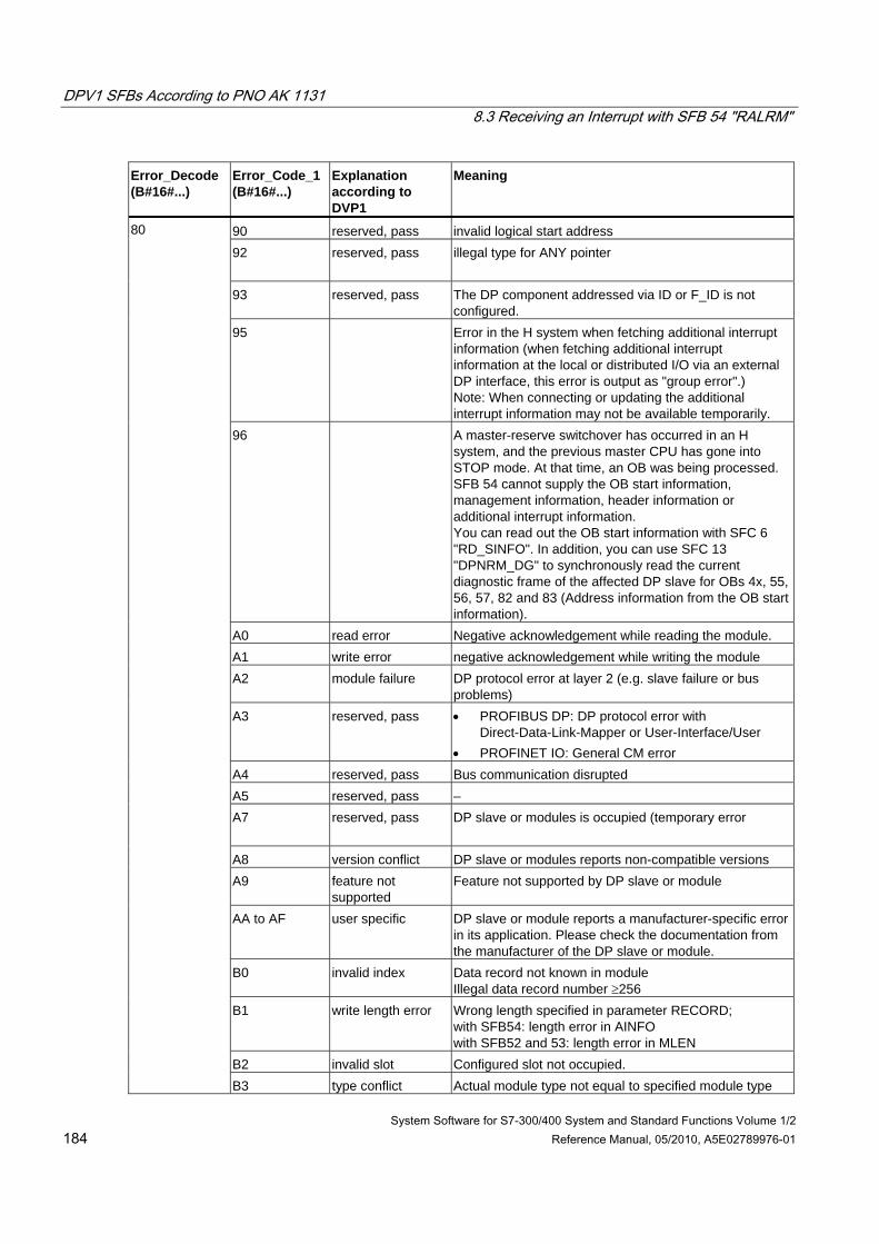
DPV1 SFBs According to PNO AK 1131 8.3 Receiving an Interrupt with SFB 54 "RALRM"
System Software for S7-300/400 System and Standard Functions Volume 1/2 184 Reference Manual, 05/2010, A5E02789976-01
Error_Decode (B#16#...)
Error_Code_1 (B#16#...)
Explanation according to DVP1
Meaning
90 reserved, pass invalid logical start address 92 reserved, pass illegal type for ANY pointer
93 reserved, pass The DP component addressed via ID or F_ID is not
configured. 95 Error in the H system when fetching additional interrupt
information (when fetching additional interrupt information at the local or distributed I/O via an external DP interface, this error is output as "group error".) Note: When connecting or updating the additional interrupt information may not be available temporarily.
96 A master-reserve switchover has occurred in an H system, and the previous master CPU has gone into STOP mode. At that time, an OB was being processed. SFB 54 cannot supply the OB start information, management information, header information or additional interrupt information. You can read out the OB start information with SFC 6 "RD_SINFO". In addition, you can use SFC 13 "DPNRM_DG" to synchronously read the current diagnostic frame of the affected DP slave for OBs 4x, 55, 56, 57, 82 and 83 (Address information from the OB start information).
A0 read error Negative acknowledgement while reading the module. A1 write error negative acknowledgement while writing the module A2 module failure DP protocol error at layer 2 (e.g. slave failure or bus
problems) A3 reserved, pass • PROFIBUS DP: DP protocol error with
Direct-Data-Link-Mapper or User-Interface/User • PROFINET IO: General CM error
A4 reserved, pass Bus communication disrupted A5 reserved, pass – A7 reserved, pass DP slave or modules is occupied (temporary error
A8 version conflict DP slave or modules reports non-compatible versions A9 feature not
supported Feature not supported by DP slave or module
AA to AF user specific DP slave or module reports a manufacturer-specific error in its application. Please check the documentation from the manufacturer of the DP slave or module.
B0 invalid index Data record not known in module Illegal data record number ≥256
B1 write length error Wrong length specified in parameter RECORD; with SFB54: length error in AINFO with SFB52 and 53: length error in MLEN
B2 invalid slot Configured slot not occupied.
80
B3 type conflict Actual module type not equal to specified module type
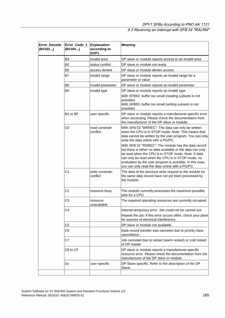
DPV1 SFBs According to PNO AK 1131 8.3 Receiving an Interrupt with SFB 54 "RALRM"
System Software for S7-300/400 System and Standard Functions Volume 1/2 Reference Manual, 05/2010, A5E02789976-01 185
Error_Decode (B#16#...)
Error_Code_1 (B#16#...)
Explanation according to DVP1
Meaning
B4 invalid area DP slave or module reports access to an invalid area B5 status conflict DP slave or module not ready B6 access denied DP slave or module denies access B7 invalid range DP slave or module reports an invalid range for a
parameter or value B8 invalid parameter DP slave or module reports an invalid parameter B9 invalid type DP slave or module reports an invalid type
With SFB52: buffer too small (reading subsets is not possible) With SFB53: buffer too small (writing subsets is not possible)
BA to BF user specific DP slave or module reports a manufacturer-specific error when accessing. Please check the documentation from the manufacturer of the DP slave or module.
C0 read constrain conflict
With SFB 53 "WRREC": The data can only be written when the CPU is in STOP mode. Note: This means that data cannot be written by the user program. You can only write the data online with a PG/PC. With SFB 52 "RDREC": The module has the data record but there is either no data available or the data can only be read when the CPU is in STOP mode. Note: If data can only be read when the CPU is in STOP mode, no evaluation by the user program is possible. In this case, you can only read the data online with a PG/PC.
C1 write constrain conflict
The data of the previous write request to the module for the same data record have not yet been processed by the module.
C2 resource busy The module currently processes the maximum possible jobs for a CPU.
C3 resource unavailable
The required operating resources are currently occupied.
C4 Internal temporary error. Job could not be carried out. Repeat the job. If this error occurs often, check your plant for sources of electrical interference.
C5 DP slave or module not available. C6 Data record transfer was canceled due to priority class
cancellation C7 Job canceled due to restart (warm restart) or cold restart
of DP master C8 to CF DP slave or module reports a manufacturer-specific
resource error. Please check the documentation from the manufacturer of the DP slave or module.
Dx user specific DP Slave specific. Refer to the description of the DP Slave.
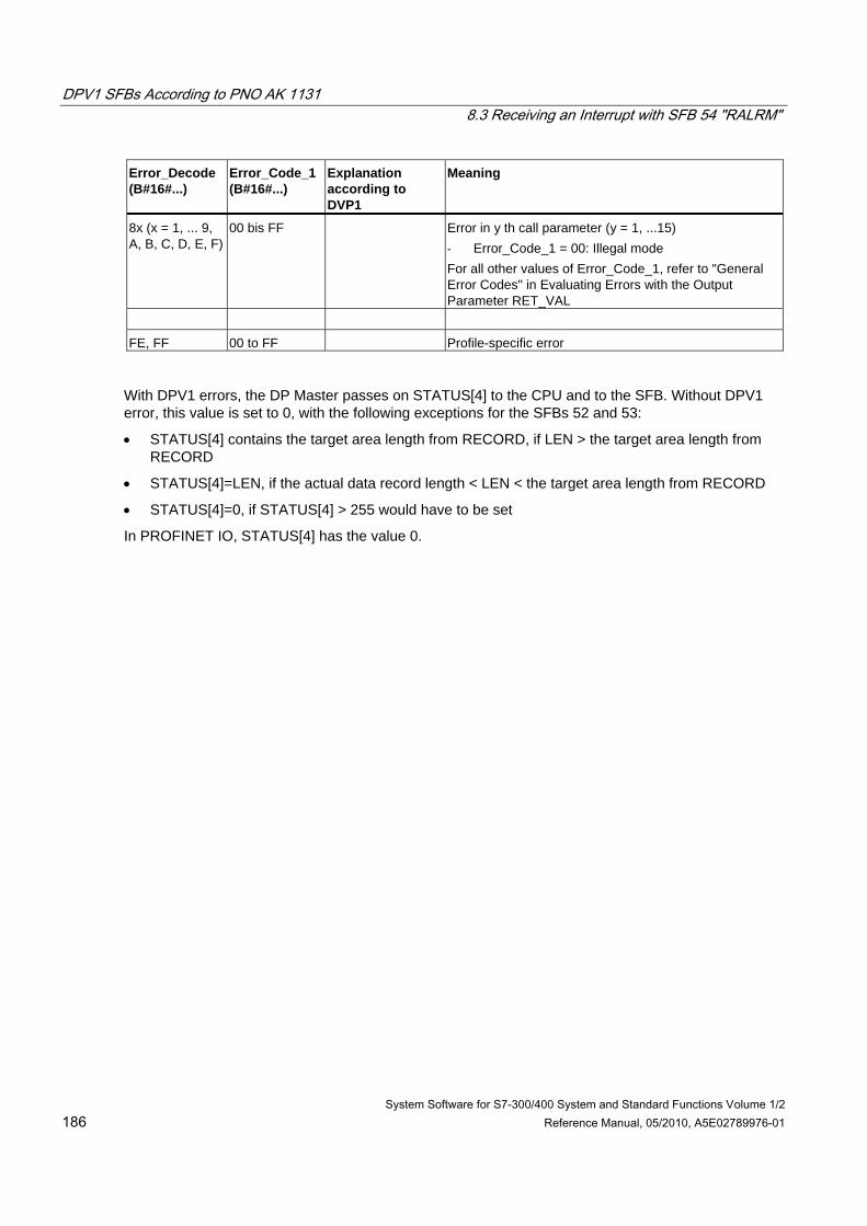
DPV1 SFBs According to PNO AK 1131 8.3 Receiving an Interrupt with SFB 54 "RALRM"
System Software for S7-300/400 System and Standard Functions Volume 1/2 186 Reference Manual, 05/2010, A5E02789976-01
Error_Decode (B#16#...)
Error_Code_1 (B#16#...)
Explanation according to DVP1
Meaning
8x (x = 1, ... 9, A, B, C, D, E, F)
00 bis FF Error in y th call parameter (y = 1, ...15) - Error_Code_1 = 00: Illegal mode For all other values of Error_Code_1, refer to "General Error Codes" in Evaluating Errors with the Output Parameter RET_VAL
FE, FF 00 to FF Profile-specific error
With DPV1 errors, the DP Master passes on STATUS[4] to the CPU and to the SFB. Without DPV1 error, this value is set to 0, with the following exceptions for the SFBs 52 and 53:
• STATUS[4] contains the target area length from RECORD, if LEN > the target area length from RECORD
• STATUS[4]=LEN, if the actual data record length < LEN < the target area length from RECORD
• STATUS[4]=0, if STATUS[4] > 255 would have to be set
In PROFINET IO, STATUS[4] has the value 0.
DPV1 SFBs According to PNO AK 1131 8.4 Sending an Interrupt to the DP Master with SFB 75 "SALRM"
System Software for S7-300/400 System and Standard Functions Volume 1/2 Reference Manual, 05/2010, A5E02789976-01 187
8.4 Sending an Interrupt to the DP Master with SFB 75 "SALRM"
Note
The SFB 75 "SALRM" interface is identical to the FB "SALRM" defined in the standard "PROFIBUS Guideline PROFIBUS Communication and Proxy Function Blocks according to IEC 61131-3"
Description SFB 75 "SALRM" sends an interrupt for a slot from the user program of an intelligent slave to the associated DP master, which accesses it in the transitional area (virtual slot). This starts the associated OB at the DP master.
You can send additional interrupt-specific information along with the interrupt. At the DP master, you can use SFB 54 "RALRM" to read all the additional information.
SFB 75 can only be used in S7-compatible mode.
• DP: The master uses a GSD file to integrate the I-slave.
• S7-compatible: The I-slave is linked to a master in STEP 7 via HW Config.
Operating principle SFB 75 "SALRM" is an asynchronous SFB, which means that its processing extends over several SFB calls. Call SFB 75 with REQ = 1 to start the transfer of the interrupt.
The send procedure remains active until interrupt processing is either acknowledged or canceled by the DP master.
Output parameter BUSY and bytes 2 and 3 of the output parameter STATUS indicate the job status, whereby STATUS bytes 2 and 3 correspond to the RET_VAL output parameter of the asynchronously operating SFCs (see also Meaning of the Parameters REQ, RET_VAL and BUSY with Asynchronous SFCs
The transfer of the interrupt is concluded when the output parameter BUSY = FALSE.
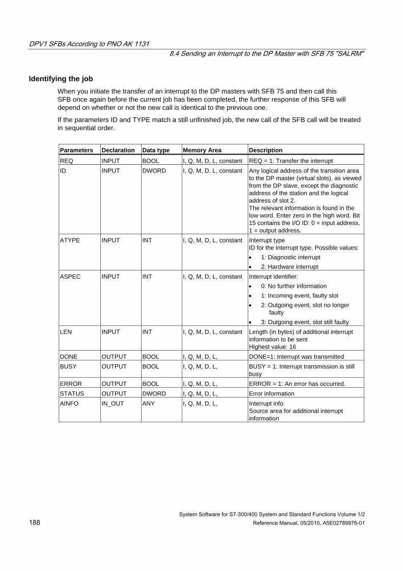
DPV1 SFBs According to PNO AK 1131 8.4 Sending an Interrupt to the DP Master with SFB 75 "SALRM"
System Software for S7-300/400 System and Standard Functions Volume 1/2 188 Reference Manual, 05/2010, A5E02789976-01
Identifying the job When you initiate the transfer of an interrupt to the DP masters with SFB 75 and then call this SFB once again before the current job has been completed, the further response of this SFB will depend on whether or not the new call is identical to the previous one.
If the parameters ID and TYPE match a still unfinished job, the new call of the SFB call will be treated in sequential order.
Parameters Declaration Data type Memory Area Description
REQ INPUT BOOL I, Q, M, D, L, constant REQ = 1: Transfer the interrupt ID INPUT DWORD I, Q, M, D, L, constant Any logical address of the transition area
to the DP master (virtual slots), as viewed from the DP slave, except the diagnostic address of the station and the logical address of slot 2. The relevant information is found in the low word. Enter zero in the high word. Bit 15 contains the I/O ID: 0 = input address, 1 = output address.
ATYPE INPUT INT I, Q, M, D, L, constant Interrupt type ID for the interrupt type. Possible values: • 1: Diagnostic interrupt • 2: Hardware interrupt
ASPEC INPUT INT I, Q, M, D, L, constant Interrupt identifier: • 0: No further information • 1: Incoming event, faulty slot • 2: Outgoing event, slot no longer
faulty • 3: Outgoing event, slot still faulty
LEN INPUT INT I, Q, M, D, L, constant Length (in bytes) of additional interrupt information to be sent Highest value: 16
DONE OUTPUT BOOL I, Q, M, D, L, DONE=1: Interrupt was transmitted BUSY OUTPUT BOOL I, Q, M, D, L, BUSY = 1: Interrupt transmission is still
busy ERROR OUTPUT BOOL I, Q, M, D, L, ERROR = 1: An error has occurred. STATUS OUTPUT DWORD I, Q, M, D, L, Error information AINFO IN_OUT ANY I, Q, M, D, L, Interrupt info
Source area for additional interrupt information
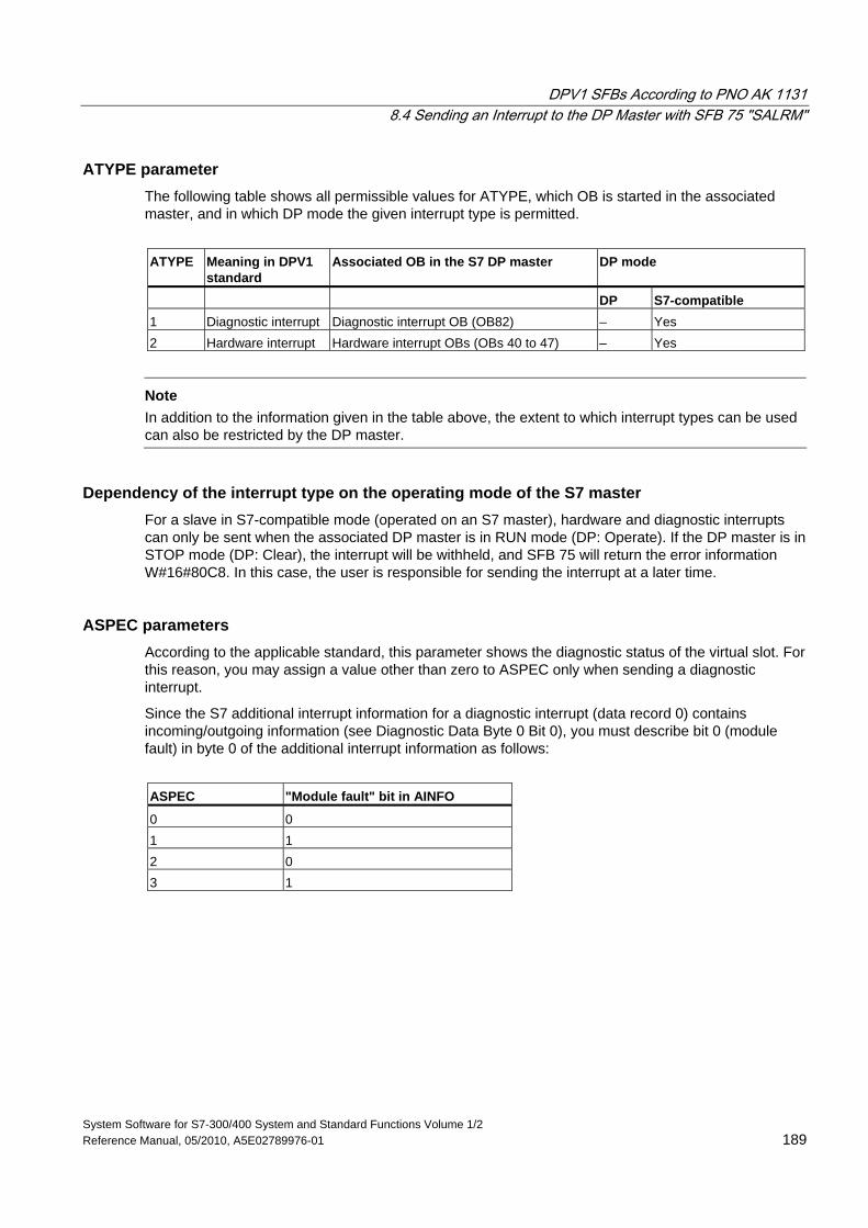
DPV1 SFBs According to PNO AK 1131 8.4 Sending an Interrupt to the DP Master with SFB 75 "SALRM"
System Software for S7-300/400 System and Standard Functions Volume 1/2 Reference Manual, 05/2010, A5E02789976-01 189
ATYPE parameter The following table shows all permissible values for ATYPE, which OB is started in the associated master, and in which DP mode the given interrupt type is permitted.
ATYPE Meaning in DPV1
standard Associated OB in the S7 DP master DP mode
DP S7-compatible 1 Diagnostic interrupt Diagnostic interrupt OB (OB82) – Yes 2 Hardware interrupt Hardware interrupt OBs (OBs 40 to 47) – Yes
Note
In addition to the information given in the table above, the extent to which interrupt types can be used can also be restricted by the DP master.
Dependency of the interrupt type on the operating mode of the S7 master For a slave in S7-compatible mode (operated on an S7 master), hardware and diagnostic interrupts can only be sent when the associated DP master is in RUN mode (DP: Operate). If the DP master is in STOP mode (DP: Clear), the interrupt will be withheld, and SFB 75 will return the error information W#16#80C8. In this case, the user is responsible for sending the interrupt at a later time.
ASPEC parameters According to the applicable standard, this parameter shows the diagnostic status of the virtual slot. For this reason, you may assign a value other than zero to ASPEC only when sending a diagnostic interrupt.
Since the S7 additional interrupt information for a diagnostic interrupt (data record 0) contains incoming/outgoing information (see Diagnostic Data Byte 0 Bit 0), you must describe bit 0 (module fault) in byte 0 of the additional interrupt information as follows:
ASPEC "Module fault" bit in AINFO
0 0 1 1 2 0 3 1
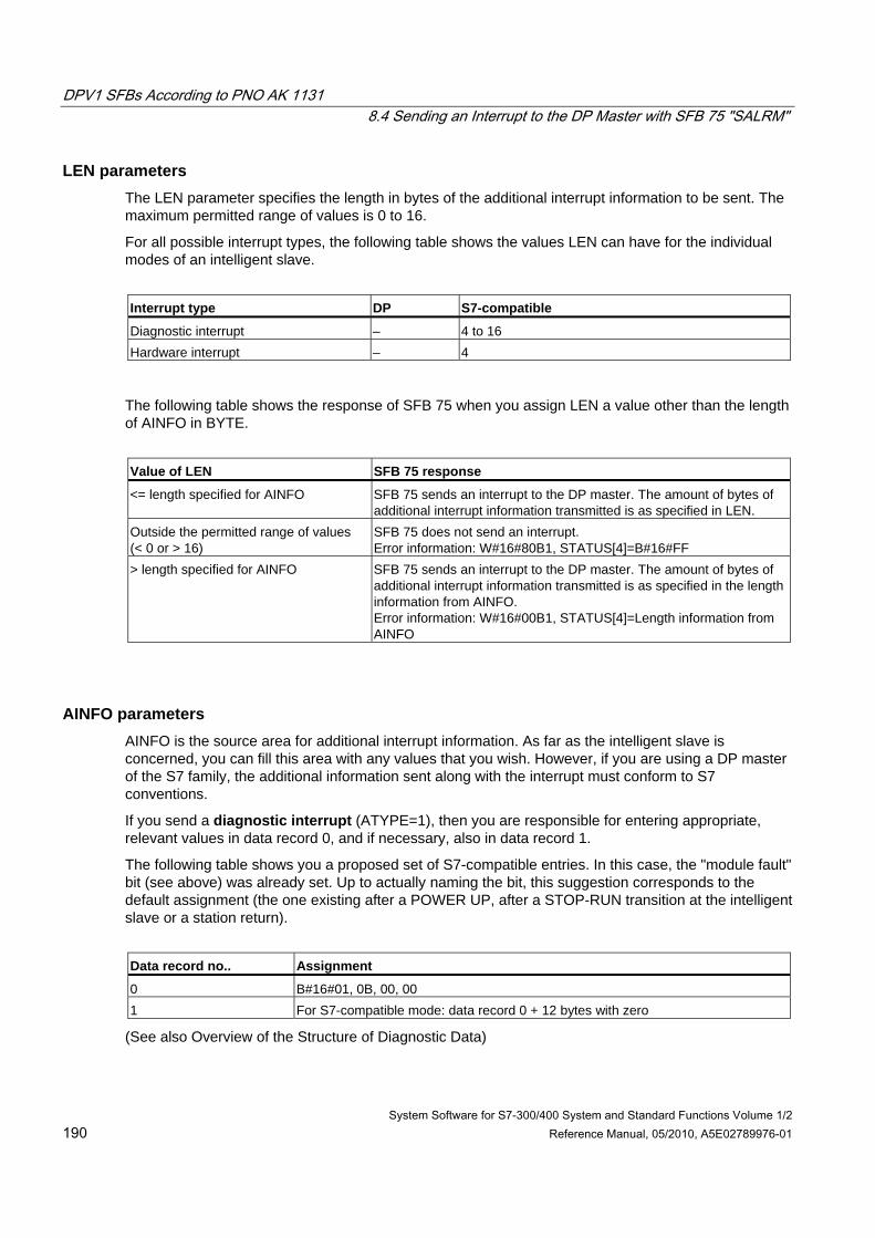
DPV1 SFBs According to PNO AK 1131 8.4 Sending an Interrupt to the DP Master with SFB 75 "SALRM"
System Software for S7-300/400 System and Standard Functions Volume 1/2 190 Reference Manual, 05/2010, A5E02789976-01
LEN parameters The LEN parameter specifies the length in bytes of the additional interrupt information to be sent. The maximum permitted range of values is 0 to 16.
For all possible interrupt types, the following table shows the values LEN can have for the individual modes of an intelligent slave.
Interrupt type DP S7-compatible
Diagnostic interrupt – 4 to 16 Hardware interrupt – 4
The following table shows the response of SFB 75 when you assign LEN a value other than the length of AINFO in BYTE.
Value of LEN SFB 75 response
<= length specified for AINFO SFB 75 sends an interrupt to the DP master. The amount of bytes of additional interrupt information transmitted is as specified in LEN.
Outside the permitted range of values (< 0 or > 16)
SFB 75 does not send an interrupt. Error information: W#16#80B1, STATUS[4]=B#16#FF
> length specified for AINFO SFB 75 sends an interrupt to the DP master. The amount of bytes of additional interrupt information transmitted is as specified in the length information from AINFO. Error information: W#16#00B1, STATUS[4]=Length information from AINFO
AINFO parameters AINFO is the source area for additional interrupt information. As far as the intelligent slave is concerned, you can fill this area with any values that you wish. However, if you are using a DP master of the S7 family, the additional information sent along with the interrupt must conform to S7 conventions.
If you send a diagnostic interrupt (ATYPE=1), then you are responsible for entering appropriate, relevant values in data record 0, and if necessary, also in data record 1.
The following table shows you a proposed set of S7-compatible entries. In this case, the "module fault" bit (see above) was already set. Up to actually naming the bit, this suggestion corresponds to the default assignment (the one existing after a POWER UP, after a STOP-RUN transition at the intelligent slave or a station return).
Data record no.. Assignment
0 B#16#01, 0B, 00, 00 1 For S7-compatible mode: data record 0 + 12 bytes with zero
(See also Overview of the Structure of Diagnostic Data)
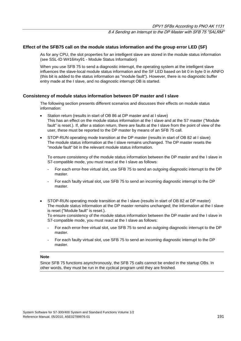
DPV1 SFBs According to PNO AK 1131 8.4 Sending an Interrupt to the DP Master with SFB 75 "SALRM"
System Software for S7-300/400 System and Standard Functions Volume 1/2 Reference Manual, 05/2010, A5E02789976-01 191
Effect of the SFB75 call on the module status information and the group error LED (SF) As for any CPU, the slot properties for an intelligent slave are stored in the module status information (see SSL-ID W#16#xy91 - Module Status Information)
When you use SFB 75 to send a diagnostic interrupt, the operating system at the intelligent slave influences the slave-local module status information and the SF LED based on bit 0 in byte 0 in AINFO (this bit is added to the status information as "module fault"). However, there is no diagnostic buffer entry made at the I slave, and no diagnostic interrupt OB is started.
Consistency of module status information between DP master and I slave The following section presents different scenarios and discusses their effects on module status information:
• Station return (results in start of OB 86 at DP master and at I slave) This has an effect on the module status information at the I slave and at the S7 master ("Module fault" is reset.). If, after a station return, there are faults at the I slave from the point of view of the user, these must be reported to the DP master by means of an SFB 75 call.
• STOP-RUN operating mode transition at the DP master (results in start of OB 82 at I slave) The module status information at the I slave remains unchanged. The DP master resets the "module fault" bit in the relevant module status information. To ensure consistency of the module status information between the DP master and the I slave in S7-compatible mode, you must react at the I slave as follows:
- For each error-free virtual slot, use SFB 75 to send an outgoing diagnostic interrupt to the DP master.
- For each faulty virtual slot, use SFB 75 to send an incoming diagnostic interrupt to the DP master.
• STOP-RUN operating mode transition at the I slave (results in start of OB 82 at DP master) The module status information at the DP master remains unchanged; the information at the I slave is reset ("Module fault" is reset.). To ensure consistency of the module status information between the DP master and the I slave in S7-compatible mode, you must react at the I slave as follows:
- For each error-free virtual slot, use SFB 75 to send an outgoing diagnostic interrupt to the DP master.
- For each faulty virtual slot, use SFB 75 to send an incoming diagnostic interrupt to the DP master.
Note
Since SFB 75 functions asynchronously, the SFB 75 calls cannot be ended in the startup OBs. In other words, they must be run in the cyclical program until they are finished.
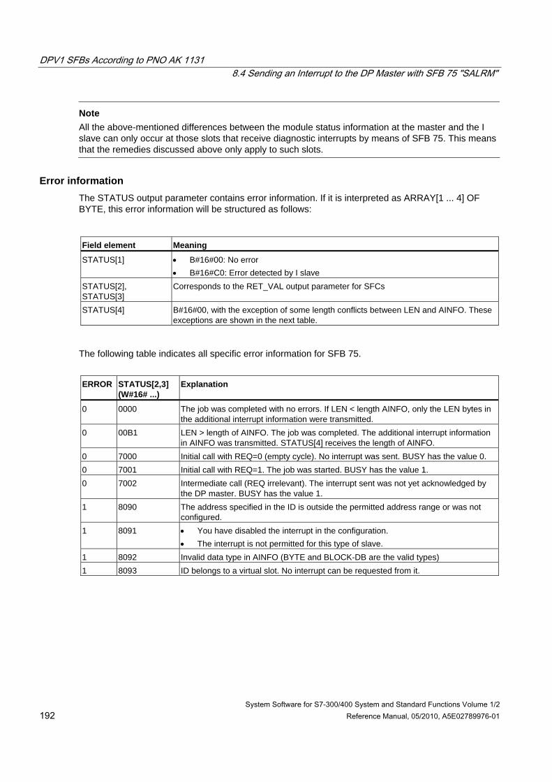
DPV1 SFBs According to PNO AK 1131 8.4 Sending an Interrupt to the DP Master with SFB 75 "SALRM"
System Software for S7-300/400 System and Standard Functions Volume 1/2 192 Reference Manual, 05/2010, A5E02789976-01
Note All the above-mentioned differences between the module status information at the master and the I slave can only occur at those slots that receive diagnostic interrupts by means of SFB 75. This means that the remedies discussed above only apply to such slots.
Error information
The STATUS output parameter contains error information. If it is interpreted as ARRAY[1 ... 4] OF BYTE, this error information will be structured as follows: Field element Meaning
STATUS[1] • B#16#00: No error • B#16#C0: Error detected by I slave
STATUS[2], STATUS[3]
Corresponds to the RET_VAL output parameter for SFCs
STATUS[4] B#16#00, with the exception of some length conflicts between LEN and AINFO. These exceptions are shown in the next table.
The following table indicates all specific error information for SFB 75.
ERROR STATUS[2,3]
(W#16# ...) Explanation
0 0000 The job was completed with no errors. If LEN < length AINFO, only the LEN bytes in the additional interrupt information were transmitted.
0 00B1 LEN > length of AINFO. The job was completed. The additional interrupt information in AINFO was transmitted. STATUS[4] receives the length of AINFO.
0 7000 Initial call with REQ=0 (empty cycle). No interrupt was sent. BUSY has the value 0. 0 7001 Initial call with REQ=1. The job was started. BUSY has the value 1. 0 7002 Intermediate call (REQ irrelevant). The interrupt sent was not yet acknowledged by
the DP master. BUSY has the value 1. 1 8090 The address specified in the ID is outside the permitted address range or was not
configured. 1 8091 • You have disabled the interrupt in the configuration.
• The interrupt is not permitted for this type of slave. 1 8092 Invalid data type in AINFO (BYTE and BLOCK-DB are the valid types) 1 8093 ID belongs to a virtual slot. No interrupt can be requested from it.
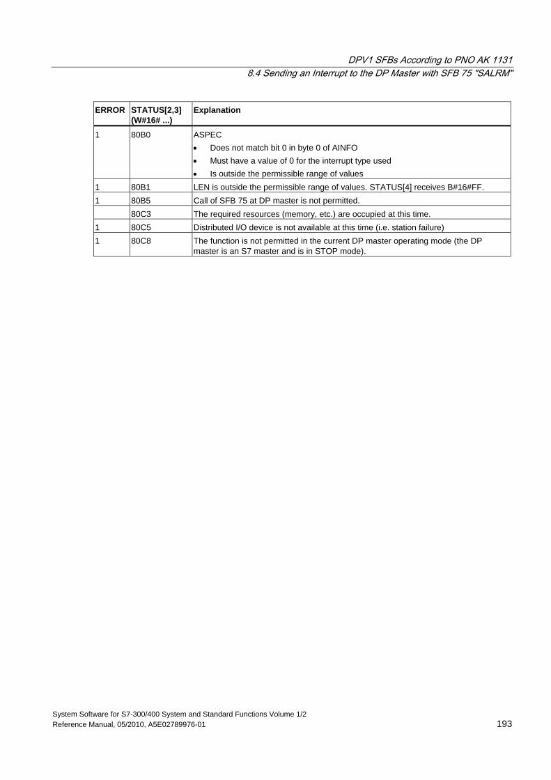
DPV1 SFBs According to PNO AK 1131 8.4 Sending an Interrupt to the DP Master with SFB 75 "SALRM"
System Software for S7-300/400 System and Standard Functions Volume 1/2 Reference Manual, 05/2010, A5E02789976-01 193
ERROR STATUS[2,3] (W#16# ...)
Explanation
1 80B0 ASPEC • Does not match bit 0 in byte 0 of AINFO • Must have a value of 0 for the interrupt type used • Is outside the permissible range of values
1 80B1 LEN is outside the permissible range of values. STATUS[4] receives B#16#FF. 1 80B5 Call of SFB 75 at DP master is not permitted. 80C3 The required resources (memory, etc.) are occupied at this time. 1 80C5 Distributed I/O device is not available at this time (i.e. station failure) 1 80C8 The function is not permitted in the current DP master operating mode (the DP
master is an S7 master and is in STOP mode).
DPV1 SFBs According to PNO AK 1131 8.5 Receiving a Data Record with SFB 73 "RCVREC"
System Software for S7-300/400 System and Standard Functions Volume 1/2 194 Reference Manual, 05/2010, A5E02789976-01
8.5 Receiving a Data Record with SFB 73 "RCVREC"
Description An I-device can receive a data record from the higher-level controller. The reception occurs in the application program with SFB 73 "RCVREC" (receive record).
The SFB 73 has the following operating modes:
• It checks whether there is a request for data reception for the I-device.
• It provides the data record to the output parameters.
• It sends a reply to the higher-level controller.
The MODE input parameter (see below) determines which of these modes SFB 73 uses.
The I-device must be in RUN or START mode.
You can use MLEN to specify the maximum number of bytes you want to receive. You should therefore set the data record target area at least MLEN bytes long.
When a data record has been received (MODE = 1 or MODE = 2), the NEW output parameter indicates that the data record has been saved in RECORD. Carefully check that RECORD has sufficient length. The LEN output parameter contains the actual length of the received data record in bytes.
Describe CODE1 and CODE 2 with zero for a positive response to the higher-level controller. If the received data record should be rejected, indicate the negative response to the higher-level controller with error code 1 in CODE1 and error code 2 in CODE2.
Note
If the I-device receives a request to receive a data record, this request must be detected within a specified time period. Once detected, you must send the higher-level controller an reply within the same time period. Otherwise, a timeout error will occur on the I-device, which results in the operating system of the I-device sending a negative reply to the higher-level controller. Refer to the specifications of your CPU for the value of the time period.
If an error occurs, the STATUS output parameter contains the error information.
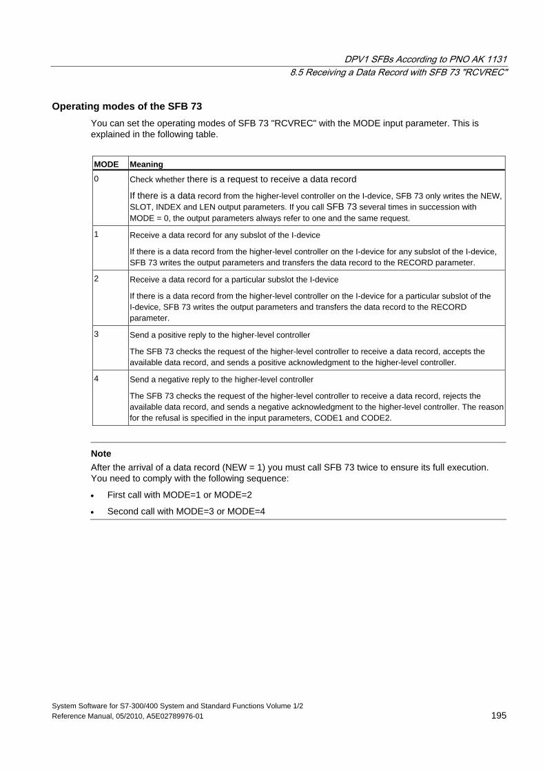
DPV1 SFBs According to PNO AK 1131 8.5 Receiving a Data Record with SFB 73 "RCVREC"
System Software for S7-300/400 System and Standard Functions Volume 1/2 Reference Manual, 05/2010, A5E02789976-01 195
Operating modes of the SFB 73 You can set the operating modes of SFB 73 "RCVREC" with the MODE input parameter. This is explained in the following table.
MODE Meaning
0 Check whether there is a request to receive a data record
If there is a data record from the higher-level controller on the I-device, SFB 73 only writes the NEW, SLOT, INDEX and LEN output parameters. If you call SFB 73 several times in succession with MODE = 0, the output parameters always refer to one and the same request.
1 Receive a data record for any subslot of the I-device
If there is a data record from the higher-level controller on the I-device for any subslot of the I-device, SFB 73 writes the output parameters and transfers the data record to the RECORD parameter.
2 Receive a data record for a particular subslot the I-device
If there is a data record from the higher-level controller on the I-device for a particular subslot of the I-device, SFB 73 writes the output parameters and transfers the data record to the RECORD parameter.
3 Send a positive reply to the higher-level controller
The SFB 73 checks the request of the higher-level controller to receive a data record, accepts the available data record, and sends a positive acknowledgment to the higher-level controller.
4 Send a negative reply to the higher-level controller
The SFB 73 checks the request of the higher-level controller to receive a data record, rejects the available data record, and sends a negative acknowledgment to the higher-level controller. The reason for the refusal is specified in the input parameters, CODE1 and CODE2.
Note
After the arrival of a data record (NEW = 1) you must call SFB 73 twice to ensure its full execution. You need to comply with the following sequence:
• First call with MODE=1 or MODE=2
• Second call with MODE=3 or MODE=4
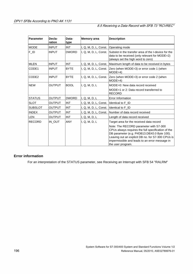
DPV1 SFBs According to PNO AK 1131 8.5 Receiving a Data Record with SFB 73 "RCVREC"
System Software for S7-300/400 System and Standard Functions Volume 1/2 196 Reference Manual, 05/2010, A5E02789976-01
Parameter Decla- ration
Data- type
Memory area Description
MODE INPUT INT I, Q, M, D, L, Const. Operating mode F_ID INPUT DWORD I, Q, M, D, L, Const. Subslot in the transfer area of the I-device for the
data to be received (only relevant for MODE=2) (always set the high word to zero)
MLEN INPUT INT I, Q, M, D, L, Const. Maximum length of data to be received in bytes CODE1 INPUT BYTE I, Q, M, D, L, Const. Zero (when MODE=3) or error code 1 (when
MODE=4) CODE2 INPUT BYTE I, Q, M, D, L, Const. Zero (when MODE=3) or error code 2 (when
MODE=4) NEW OUTPUT BOOL I, Q, M, D, L MODE=0: New data record received
MODE=1 or 2: Data record transferred to RECORD
STATUS OUTPUT DWORD I, Q, M, D, L Error Information SLOT OUTPUT INT I, Q, M, D, L, Const. Identical to F_ID SUBSLOT OUTPUT INT I, Q, M, D, L, Const. Identical to F_ID INDEX OUTPUT INT I, Q, M, D, L, Const. Number of data record received LEN OUTPUT INT I, Q, M, D, L Length of data record received RECORD IN_OUT ANY I, Q, M, D, L Target area for the received data record
Note: The RECORD parameter with S7-300 CPUs always requires the full specification of the DB parameter (e.g. P#DB13.DBX0.0 Byte 100). Leaving out an explicit DB no. for S7-300 CPUs is impermissible and leads to an error message in the user program.
Error information For an interpretation of the STATUS parameter, see Receiving an Interrupt with SFB 54 "RALRM"
DPV1 SFBs According to PNO AK 1131 8.6 Providing a Data Record with SFB 74 "PRVREC"
System Software for S7-300/400 System and Standard Functions Volume 1/2 Reference Manual, 05/2010, A5E02789976-01 197
8.6 Providing a Data Record with SFB 74 "PRVREC"
Description An I- device may receive a request from the higher-level controller to provide a data record. This task is performed in the application program with the SFB 74 "PRVREC" (provide record).
The SFB 74 has the following modes:
• It checks whether there is a request to provide a data record for the I-device.
• It sends the requested data record to the higher-level controller.
• It sends a reply to the higher-level controller.
The MODE input parameter (see below) determines which of these modes SFB 74 uses.
The I-device must be in RUN or START mode.
You can use LEN to specify the maximum number of bytes you want to receive. You should therefore set the data record target area at least LEN bytes long.
When a request to provide a data record is pending (MODE = 0), the NEW output parameter is set to TRUE.
If the request to provide a data record is accepted, as a positive response to the higher-level controller, write the requested record to RECORD and CODE1 and CODE 2 with zero. If the request to provide a data record should be rejected, indicate the negative response to the higher-level controller with error code 1 in CODE1 and error code 2 in CODE2.
Note
If the I-device receives a request to provide a data record, this request must be detected within a specified time period. Once detected, you must send the higher-level controller an reply within the same time period. Otherwise, a timeout error will occur on the I-device, which results in the operating system of the I-device sending a negative reply to the higher-level controller. Refer to the specifications of your CPU for the value of the time period.
If an error occurs, the STATUS output parameter contains the error information.
DPV1 SFBs According to PNO AK 1131 8.6 Providing a Data Record with SFB 74 "PRVREC"
System Software for S7-300/400 System and Standard Functions Volume 1/2 198 Reference Manual, 05/2010, A5E02789976-01
Operating modes of the SFB 74 You can set the operating modes of SFB 74 "PRVREC" with the MODE input parameter. This is explained in the following table.
MODE Meaning
0 Check whether there is a request to provide a data record If there is a request to provide a data record on the I-device from the higher-level controller, SFB 74 only writes the NEW, SLOT, INDEX, and RLEN output parameters. If you call SFB 74 several times in succession with MODE = 0, the output parameters always refer to one and the same request.
1 Receive a request for providing a data record for any subslot of the I-device If there is such a request from the higher-level controller on the I-device for any subslot of the I-device, SFB 74 writes the output parameters.
2 Receive a request for providing a data record for a particular subslot of the I-device If there is such a request from the higher-level controller on the I-device for a particular subslot of the I-device is present, SFB 74 writes the output parameters.
3 Provide data and send a positive reply to the higher-level controller The SFB 74 checks the request of the higher-level controller to provide a data record, makes the requested record available in RECORD and sends a positive acknowledgment to the higher-level controller.
4 Negative response to the higher-level to send controller The SFB 74 checks the request of the higher-level controller to provide a data record , rejects this request and sends a negative acknowledgment to the higher-level controller. The reason for the refusal is specified in the input parameters, CODE1 and CODE2.
Note
After the arrival of a request (NEW = 1) you must call the SFB 74 twice to ensure its full execution of. You need to comply with the following sequence:
• First call with MODE=1 or MODE=2
• Second call with MODE=3 or MODE=4
DPV1 SFBs According to PNO AK 1131 8.6 Providing a Data Record with SFB 74 "PRVREC"
System Software for S7-300/400 System and Standard Functions Volume 1/2 Reference Manual, 05/2010, A5E02789976-01 199
Parameter Decla- ration
Data- type
Memory area Description
MODE INPUT INT I, Q, M, D, L, Const. Operating mode F_ID INPUT DWORD I, Q, M, D, L, Const. Subslot in the transfer area of the I-device for the
data to be sent (only relevant for MODE=2) (always set the high word to zero)
CODE1 INPUT BYTE I, Q, M, D, L, Const. Zero (when MODE=3) or error code 1 (when MODE = 4)
CODE2 INPUT BYTE I, Q, M, D, L, Const. Zero (when MODE=3) or error code 2 (when MODE=4)
LEN INPUT INT I, Q, M, D, L, Const. Maximum length of data to be sent in bytes NEW OUTPUT BOOL I, Q, M, D, L New data was requested by the higher-level
controller STATUS OUTPUT DWORD I, Q, M, D, L Error Information SLOT OUTPUT INT I, Q, M, D, L, Const. Identical to F_ID SUBSLOT OUTPUT INT I, Q, M, D, L, Const. Identical to F_ID INDEX OUTPUT INT I, Q, M, D, L, Const. Number of the data records to be sent RLEN OUTPUT INT I, Q, M, D, L Length of data record to be sent RECORD IN_OUT ANY I, Q, M, D, L Data record provided
Note: The RECORD parameter with S7-300 CPUs always requires the full specification of the DB parameter (e.g. P#DB13.DBX0.0 Byte 100). Leaving out an explicit DB no. for S7-300 CPUs is impermissible and leads to an error message in the user program.
Error information For an interpretation of the STATUS parameter, see Receiving an Interrupt with SFB 54 "RALRM"
DPV1 SFBs According to PNO AK 1131 8.6 Providing a Data Record with SFB 74 "PRVREC"
System Software for S7-300/400 System and Standard Functions Volume 1/2 200 Reference Manual, 05/2010, A5E02789976-01
System Software for S7-300/400 System and Standard Functions Volume 1/2 Reference Manual, 05/2010, A5E02789976-01 201
9 SFCs for Handling Time-of-Day Interrupts
9.1 Handling Time-of-Day Interrupts
Definition A time-of-day interrupt results in one of the time-of-day interrupt OBs (OB10 to OB17) being called.
Conditions for the Call Before a time-of-day interrupt OB can be called by the operating system, the following conditions must be met:
• The time-of-day interrupt OB must have parameters assigned to it (start date and time, execution) using either
- STEP 7 or
- SFC 28 "SET_TINT" in the user program.
• The time-of-day interrupt OB must be activated using
- STEP 7 or
- SFC 30 "ACT_TINT" in the user program.
• The time-of-day interrupt OB must not be deselected with STEP 7.
• The time-of-day interrupt OB must exist in the CPU.
• If you set the interrupt with SFC 30 "ACT_TINT" and if you have specified the execution of the OB as once only, the start date and time must not yet have passed. If you have selected periodic execution, the time-of-day interrupt OB will be called when the next period is completed (start time + multiple of the specified period).
Hint You can assign parameters to the time-of-day interrupt using STEP 7 and then activate the interrupt in your user program (SFC 30 "ACT_TINT").
Purpose of SFC 28 to SFC 31 The system functions SFC 28 to SFC 31 described in the following sections are used as follows:
• To set time-of-day interrupts (SFC 28 "SET_TINT")
• To cancel time-of-day interrupts (SFC 29 "CAN_TINT")
• To activate time-of-day interrupts (SFC 30 "ACT_TINT")
• To query time-of-day interrupts (SFC 31 "QRY_TINT")
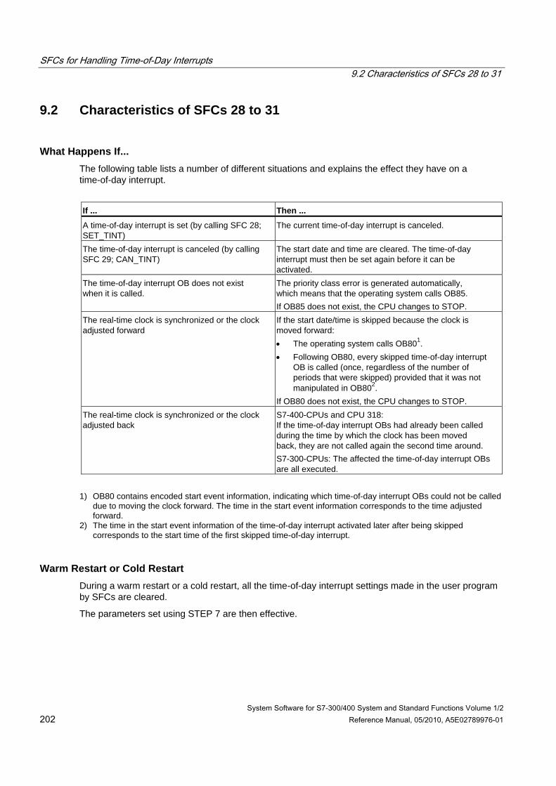
SFCs for Handling Time-of-Day Interrupts 9.2 Characteristics of SFCs 28 to 31
System Software for S7-300/400 System and Standard Functions Volume 1/2 202 Reference Manual, 05/2010, A5E02789976-01
9.2 Characteristics of SFCs 28 to 31
What Happens If... The following table lists a number of different situations and explains the effect they have on a time-of-day interrupt.
If ... Then ...
A time-of-day interrupt is set (by calling SFC 28; SET_TINT)
The current time-of-day interrupt is canceled.
The time-of-day interrupt is canceled (by calling SFC 29; CAN_TINT)
The start date and time are cleared. The time-of-day interrupt must then be set again before it can be activated.
The time-of-day interrupt OB does not exist when it is called.
The priority class error is generated automatically, which means that the operating system calls OB85. If OB85 does not exist, the CPU changes to STOP.
The real-time clock is synchronized or the clock adjusted forward
If the start date/time is skipped because the clock is moved forward: • The operating system calls OB801. • Following OB80, every skipped time-of-day interrupt
OB is called (once, regardless of the number of periods that were skipped) provided that it was not manipulated in OB802.
If OB80 does not exist, the CPU changes to STOP. The real-time clock is synchronized or the clock adjusted back
S7-400-CPUs and CPU 318: If the time-of-day interrupt OBs had already been called during the time by which the clock has been moved back, they are not called again the second time around. S7-300-CPUs: The affected the time-of-day interrupt OBs are all executed.
1) OB80 contains encoded start event information, indicating which time-of-day interrupt OBs could not be called
due to moving the clock forward. The time in the start event information corresponds to the time adjusted forward.
2) The time in the start event information of the time-of-day interrupt activated later after being skipped corresponds to the start time of the first skipped time-of-day interrupt.
Warm Restart or Cold Restart During a warm restart or a cold restart, all the time-of-day interrupt settings made in the user program by SFCs are cleared.
The parameters set using STEP 7 are then effective.
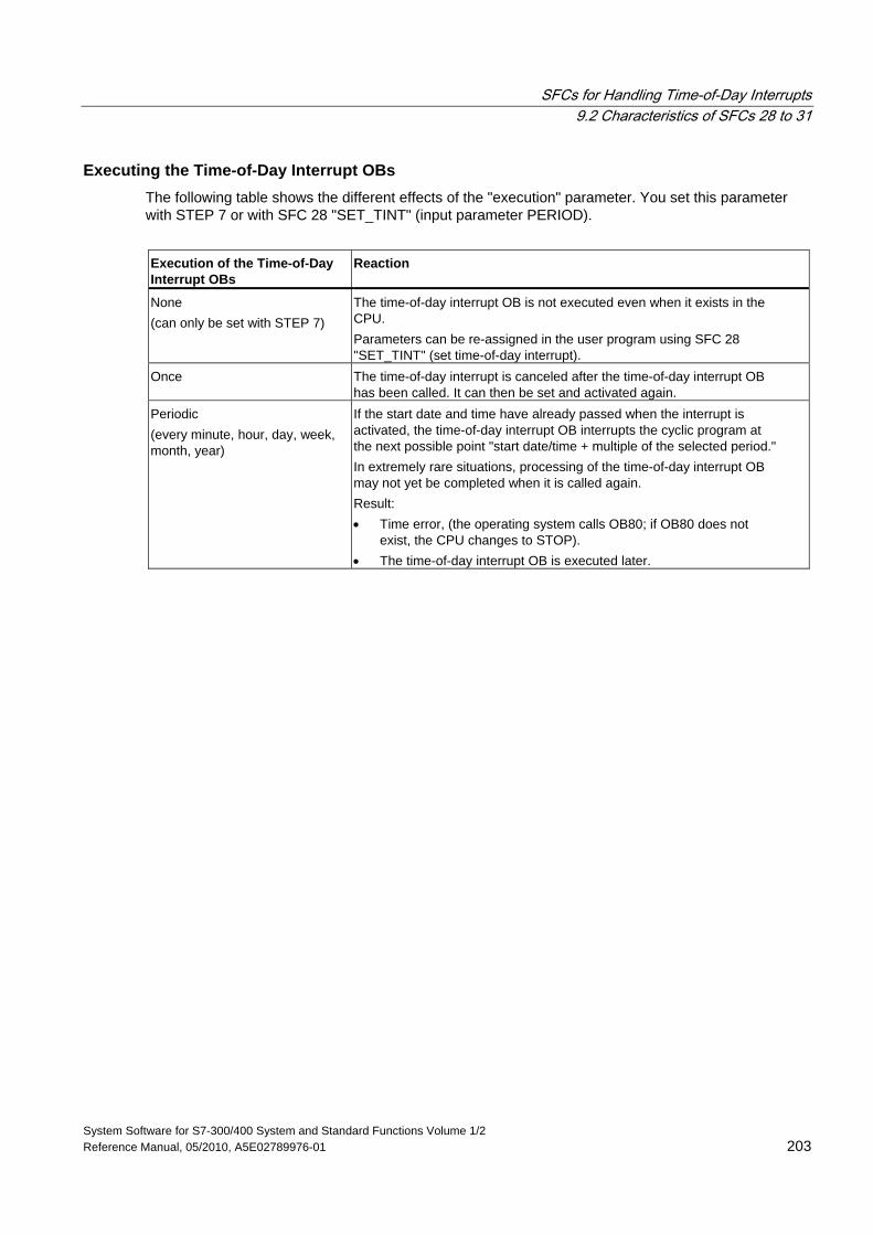
SFCs for Handling Time-of-Day Interrupts 9.2 Characteristics of SFCs 28 to 31
System Software for S7-300/400 System and Standard Functions Volume 1/2 Reference Manual, 05/2010, A5E02789976-01 203
Executing the Time-of-Day Interrupt OBs The following table shows the different effects of the "execution" parameter. You set this parameter with STEP 7 or with SFC 28 "SET_TINT" (input parameter PERIOD).
Execution of the Time-of-Day Interrupt OBs
Reaction
None (can only be set with STEP 7)
The time-of-day interrupt OB is not executed even when it exists in the CPU. Parameters can be re-assigned in the user program using SFC 28 "SET_TINT" (set time-of-day interrupt).
Once The time-of-day interrupt is canceled after the time-of-day interrupt OB has been called. It can then be set and activated again.
Periodic (every minute, hour, day, week, month, year)
If the start date and time have already passed when the interrupt is activated, the time-of-day interrupt OB interrupts the cyclic program at the next possible point "start date/time + multiple of the selected period." In extremely rare situations, processing of the time-of-day interrupt OB may not yet be completed when it is called again. Result: • Time error, (the operating system calls OB80; if OB80 does not
exist, the CPU changes to STOP). • The time-of-day interrupt OB is executed later.
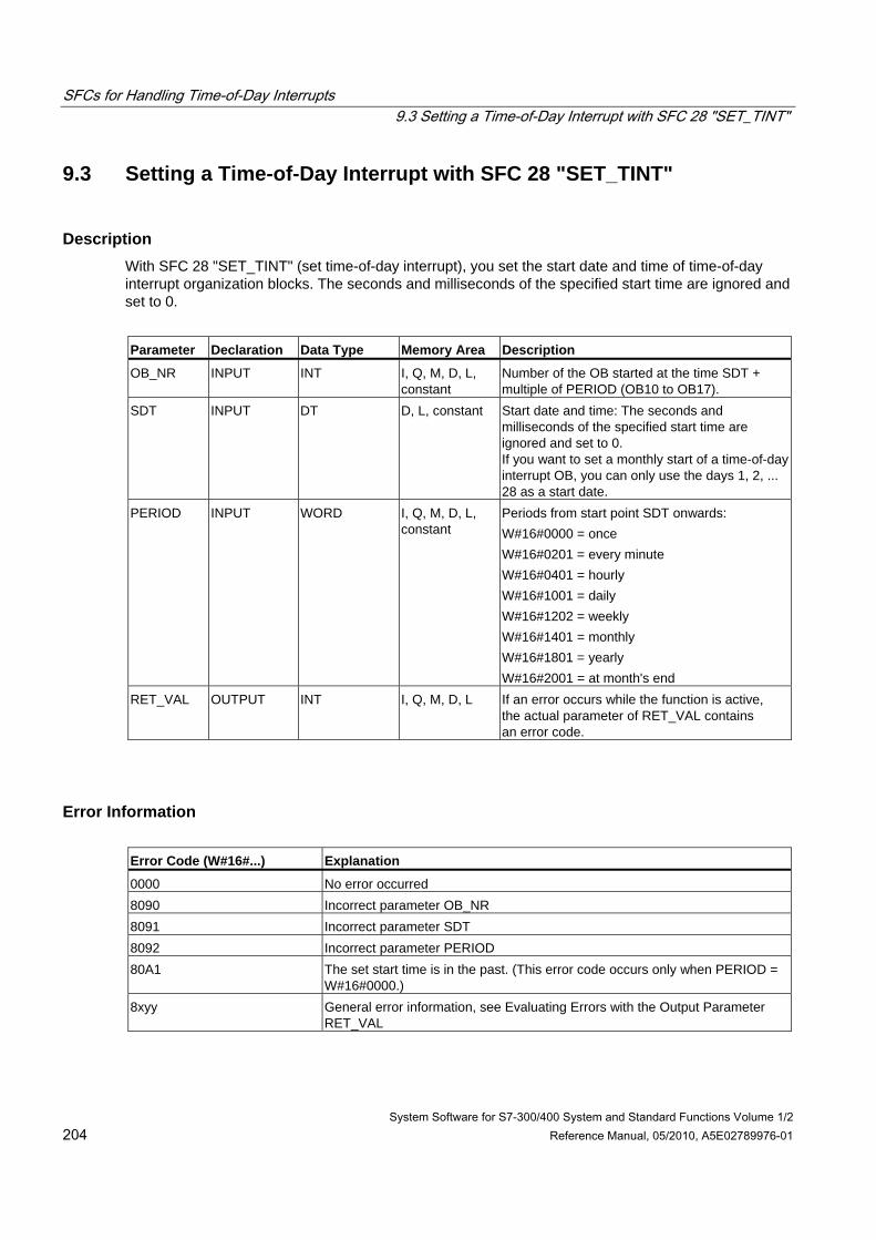
SFCs for Handling Time-of-Day Interrupts 9.3 Setting a Time-of-Day Interrupt with SFC 28 "SET_TINT"
System Software for S7-300/400 System and Standard Functions Volume 1/2 204 Reference Manual, 05/2010, A5E02789976-01
9.3 Setting a Time-of-Day Interrupt with SFC 28 "SET_TINT"
Description With SFC 28 "SET_TINT" (set time-of-day interrupt), you set the start date and time of time-of-day interrupt organization blocks. The seconds and milliseconds of the specified start time are ignored and set to 0.
Parameter Declaration Data Type Memory Area Description
OB_NR INPUT INT I, Q, M, D, L, constant
Number of the OB started at the time SDT + multiple of PERIOD (OB10 to OB17).
SDT INPUT DT D, L, constant Start date and time: The seconds and milliseconds of the specified start time are ignored and set to 0. If you want to set a monthly start of a time-of-day interrupt OB, you can only use the days 1, 2, ... 28 as a start date.
PERIOD INPUT WORD I, Q, M, D, L, constant
Periods from start point SDT onwards: W#16#0000 = once W#16#0201 = every minute W#16#0401 = hourly W#16#1001 = daily W#16#1202 = weekly W#16#1401 = monthly W#16#1801 = yearly W#16#2001 = at month's end
RET_VAL OUTPUT INT I, Q, M, D, L If an error occurs while the function is active, the actual parameter of RET_VAL contains an error code.
Error Information Error Code (W#16#...) Explanation
0000 No error occurred 8090 Incorrect parameter OB_NR 8091 Incorrect parameter SDT 8092 Incorrect parameter PERIOD 80A1 The set start time is in the past. (This error code occurs only when PERIOD =
W#16#0000.) 8xyy General error information, see Evaluating Errors with the Output Parameter
RET_VAL
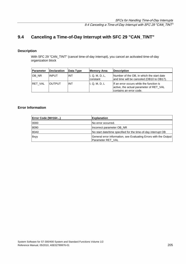
SFCs for Handling Time-of-Day Interrupts 9.4 Canceling a Time-of-Day Interrupt with SFC 29 "CAN_TINT"
System Software for S7-300/400 System and Standard Functions Volume 1/2 Reference Manual, 05/2010, A5E02789976-01 205
9.4 Canceling a Time-of-Day Interrupt with SFC 29 "CAN_TINT"
Description With SFC 29 "CAN_TINT" (cancel time-of-day interrupt), you cancel an activated time-of-day organization block
Parameter Declaration Data Type Memory Area Description
OB_NR INPUT INT I, Q, M, D, L, constant
Number of the OB, in which the start date and time will be canceled (OB10 to OB17).
RET_VAL OUTPUT INT I, Q, M, D, L If an error occurs while the function is active, the actual parameter of RET_VAL contains an error code.
Error Information Error Code (W#16#...) Explanation
0000 No error occurred. 8090 Incorrect parameter OB_NR 80A0 No start date/time specified for the time-of-day interrupt OB 8xyy General error information, see Evaluating Errors with the Output
Parameter RET_VAL
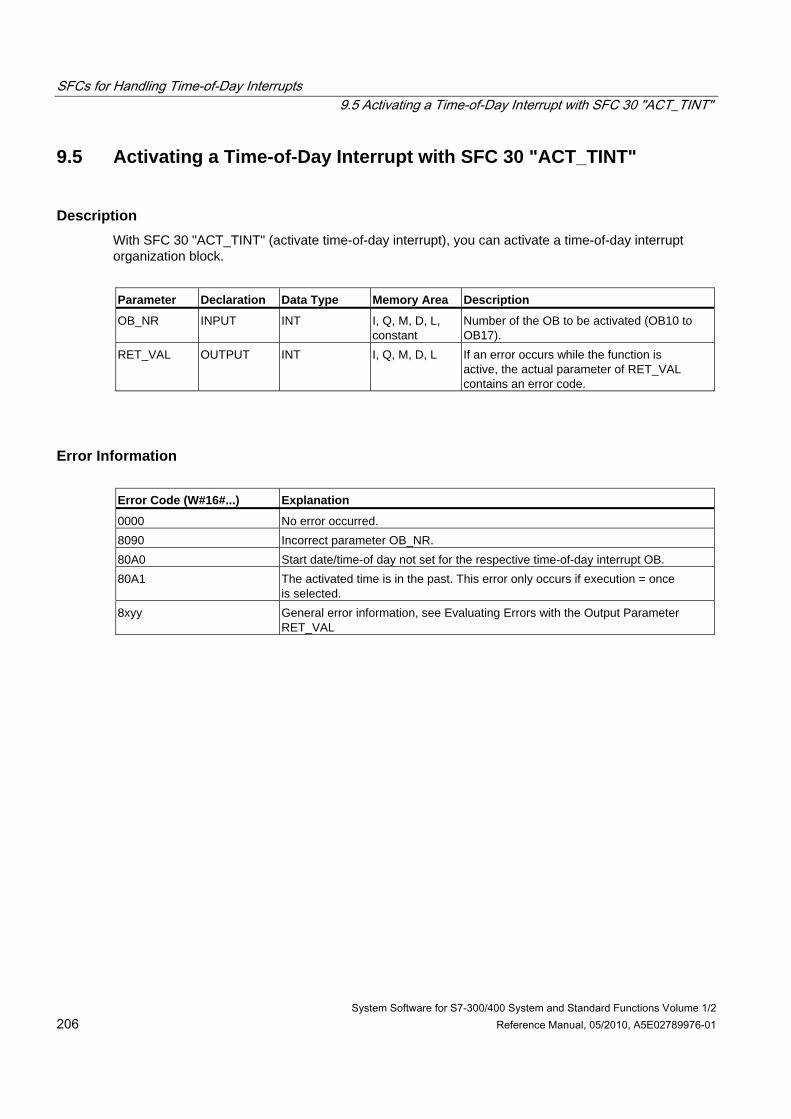
SFCs for Handling Time-of-Day Interrupts 9.5 Activating a Time-of-Day Interrupt with SFC 30 "ACT_TINT"
System Software for S7-300/400 System and Standard Functions Volume 1/2 206 Reference Manual, 05/2010, A5E02789976-01
9.5 Activating a Time-of-Day Interrupt with SFC 30 "ACT_TINT"
Description With SFC 30 "ACT_TINT" (activate time-of-day interrupt), you can activate a time-of-day interrupt organization block.
Parameter Declaration Data Type Memory Area Description
OB_NR INPUT INT I, Q, M, D, L, constant
Number of the OB to be activated (OB10 to OB17).
RET_VAL OUTPUT INT I, Q, M, D, L If an error occurs while the function is active, the actual parameter of RET_VAL contains an error code.
Error Information Error Code (W#16#...) Explanation
0000 No error occurred. 8090 Incorrect parameter OB_NR. 80A0 Start date/time-of day not set for the respective time-of-day interrupt OB. 80A1 The activated time is in the past. This error only occurs if execution = once
is selected. 8xyy General error information, see Evaluating Errors with the Output Parameter
RET_VAL
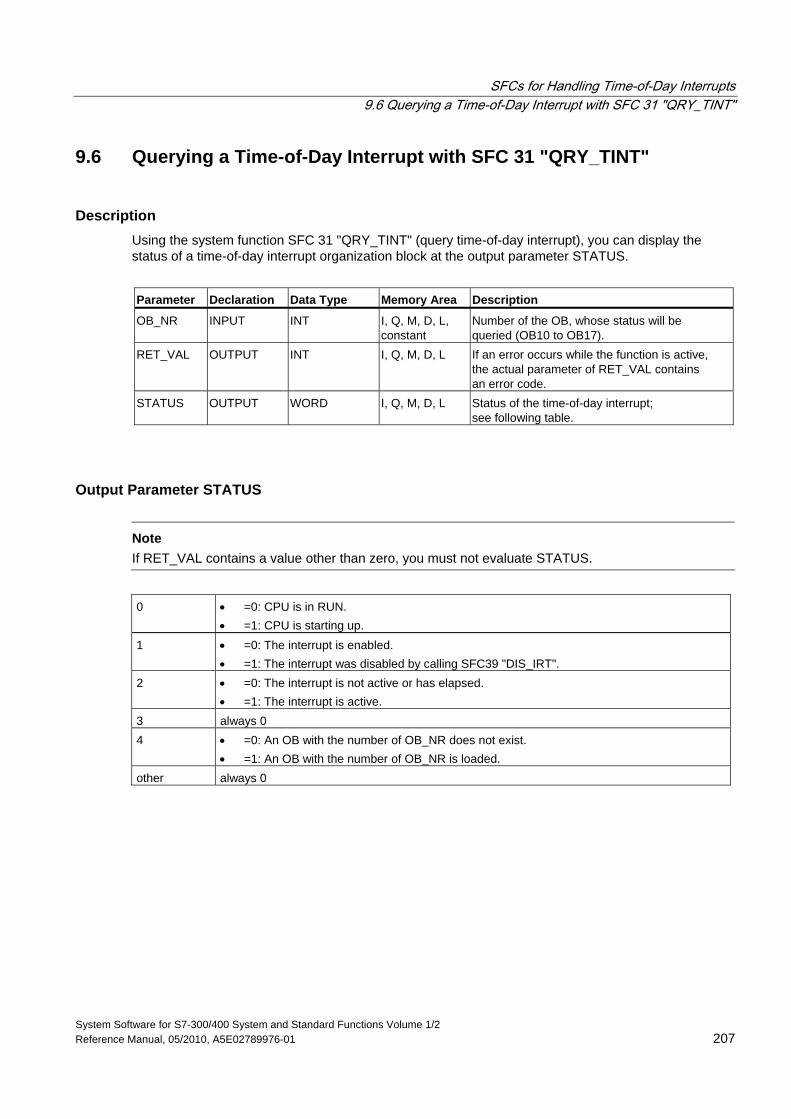
SFCs for Handling Time-of-Day Interrupts 9.6 Querying a Time-of-Day Interrupt with SFC 31 "QRY_TINT"
System Software for S7-300/400 System and Standard Functions Volume 1/2 Reference Manual, 05/2010, A5E02789976-01 207
9.6 Querying a Time-of-Day Interrupt with SFC 31 "QRY_TINT"
Description Using the system function SFC 31 "QRY_TINT" (query time-of-day interrupt), you can display the status of a time-of-day interrupt organization block at the output parameter STATUS.
Parameter Declaration Data Type Memory Area Description
OB_NR INPUT INT I, Q, M, D, L, constant
Number of the OB, whose status will be queried (OB10 to OB17).
RET_VAL OUTPUT INT I, Q, M, D, L If an error occurs while the function is active, the actual parameter of RET_VAL contains an error code.
STATUS OUTPUT WORD I, Q, M, D, L Status of the time-of-day interrupt; see following table.
Output Parameter STATUS
Note If RET_VAL contains a value other than zero, you must not evaluate STATUS.
0 • =0: CPU is in RUN.
• =1: CPU is starting up. 1 • =0: The interrupt is enabled.
• =1: The interrupt was disabled by calling SFC39 "DIS_IRT". 2 • =0: The interrupt is not active or has elapsed.
• =1: The interrupt is active. 3 always 0 4 • =0: An OB with the number of OB_NR does not exist.
• =1: An OB with the number of OB_NR is loaded. other always 0
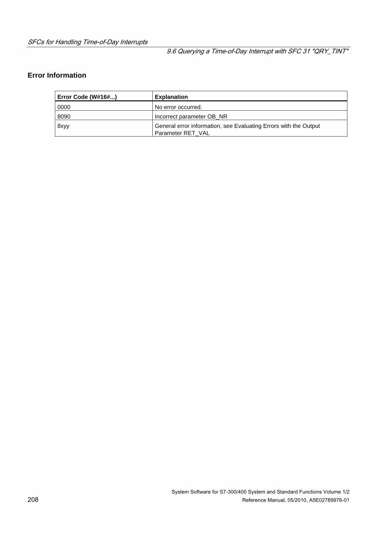
SFCs for Handling Time-of-Day Interrupts 9.6 Querying a Time-of-Day Interrupt with SFC 31 "QRY_TINT"
System Software for S7-300/400 System and Standard Functions Volume 1/2 208 Reference Manual, 05/2010, A5E02789976-01
Error Information Error Code (W#16#...) Explanation
0000 No error occurred. 8090 Incorrect parameter OB_NR 8xyy General error information, see Evaluating Errors with the Output
Parameter RET_VAL
System Software for S7-300/400 System and Standard Functions Volume 1/2 Reference Manual, 05/2010, A5E02789976-01 209
10 SFCs for Handling Time-Delay Interrupts
10.1 Handling Time-Delay Interrupts
Definition After you have called SFC 32 "SRT_DINT," the operating system generates an interrupt after the specified delay time has elapsed, in other words, the selected time-delay interrupt OB is called. This interrupt is known as a time-delay interrupt.
Conditions for the Call Before a time-delay interrupt OB can be called by the operating system, the following conditions must be met:
• The time-delay interrupt OB must be started by SFC 32 "SRT_DINT."
• The time-delay interrupt OB must not be deselected with STEP 7.
• The time-delay interrupt OB must exist in the CPU.
Purpose of SFC 32 to SFC 34 The system functions SFC 32 to SFC 34 described in the following sections are used as follows:
• To start time-delay interrupts (SFC 32 "SRT_DINT")
• To cancel time-delay interrupts (SFC 33 "CAN_DINT")
• To query time-delay interrupts (SFC 34 "QRY_DINT").
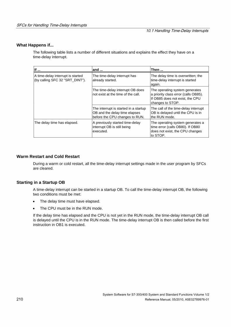
SFCs for Handling Time-Delay Interrupts 10.1 Handling Time-Delay Interrupts
System Software for S7-300/400 System and Standard Functions Volume 1/2 210 Reference Manual, 05/2010, A5E02789976-01
What Happens if... The following table lists a number of different situations and explains the effect they have on a time-delay interrupt.
If ... and ... Then ...
The time-delay interrupt has already started.
The delay time is overwritten; the time-delay interrupt is started again.
The time-delay interrupt OB does not exist at the time of the call.
The operating system generates a priority class error (calls OB85). If OB85 does not exist, the CPU changes to STOP.
A time-delay interrupt is started (by calling SFC 32 "SRT_DINT").
The interrupt is started in a startup OB and the delay time elapses before the CPU changes to RUN.
The call of the time-delay interrupt OB is delayed until the CPU is in the RUN mode.
The delay time has elapsed. A previously started time-delay interrupt OB is still being executed.
The operating system generates a time error (calls OB80). If OB80 does not exist, the CPU changes to STOP.
Warm Restart and Cold Restart During a warm or cold restart, all the time-delay interrupt settings made in the user program by SFCs are cleared.
Starting in a Startup OB A time-delay interrupt can be started in a startup OB. To call the time-delay interrupt OB, the following two conditions must be met:
• The delay time must have elapsed.
• The CPU must be in the RUN mode.
If the delay time has elapsed and the CPU is not yet in the RUN mode, the time-delay interrupt OB call is delayed until the CPU is in the RUN mode. The time-delay interrupt OB is then called before the first instruction in OB1 is executed.
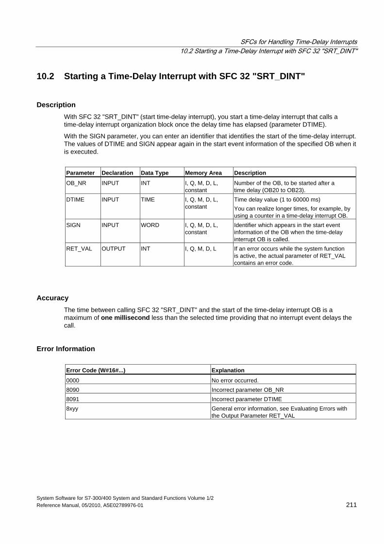
SFCs for Handling Time-Delay Interrupts 10.2 Starting a Time-Delay Interrupt with SFC 32 "SRT_DINT"
System Software for S7-300/400 System and Standard Functions Volume 1/2 Reference Manual, 05/2010, A5E02789976-01 211
10.2 Starting a Time-Delay Interrupt with SFC 32 "SRT_DINT"
Description With SFC 32 "SRT_DINT" (start time-delay interrupt), you start a time-delay interrupt that calls a time-delay interrupt organization block once the delay time has elapsed (parameter DTIME).
With the SIGN parameter, you can enter an identifier that identifies the start of the time-delay interrupt. The values of DTIME and SIGN appear again in the start event information of the specified OB when it is executed.
Parameter Declaration Data Type Memory Area Description
OB_NR INPUT INT I, Q, M, D, L, constant
Number of the OB, to be started after a time delay (OB20 to OB23).
DTIME INPUT TIME I, Q, M, D, L, constant
Time delay value (1 to 60000 ms) You can realize longer times, for example, by using a counter in a time-delay interrupt OB.
SIGN INPUT WORD I, Q, M, D, L, constant
Identifier which appears in the start event information of the OB when the time-delay interrupt OB is called.
RET_VAL OUTPUT INT I, Q, M, D, L If an error occurs while the system function is active, the actual parameter of RET_VAL contains an error code.
Accuracy The time between calling SFC 32 "SRT_DINT" and the start of the time-delay interrupt OB is a maximum of one millisecond less than the selected time providing that no interrupt event delays the call.
Error Information Error Code (W#16#...) Explanation
0000 No error occurred. 8090 Incorrect parameter OB_NR 8091 Incorrect parameter DTIME 8xyy General error information, see Evaluating Errors with
the Output Parameter RET_VAL
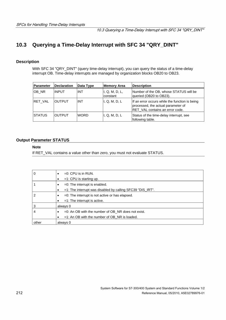
SFCs for Handling Time-Delay Interrupts 10.3 Querying a Time-Delay Interrupt with SFC 34 "QRY_DINT"
System Software for S7-300/400 System and Standard Functions Volume 1/2 212 Reference Manual, 05/2010, A5E02789976-01
10.3 Querying a Time-Delay Interrupt with SFC 34 "QRY_DINT"
Description With SFC 34 "QRY_DINT" (query time-delay interrupt), you can query the status of a time-delay interrupt OB. Time-delay interrupts are managed by organization blocks OB20 to OB23.
Parameter Declaration Data Type Memory Area Description
OB_NR INPUT INT I, Q, M, D, L, constant
Number of the OB, whose STATUS will be queried (OB20 to OB23).
RET_VAL OUTPUT INT I, Q, M, D, L If an error occurs while the function is being processed, the actual parameter of RET_VAL contains an error code.
STATUS OUTPUT WORD I, Q, M, D, L Status of the time-delay interrupt, see following table.
Output Parameter STATUS Note
If RET_VAL contains a value other than zero, you must not evaluate STATUS.
0 • =0: CPU is in RUN.
• =1: CPU is starting up. 1 • =0: The interrupt is enabled.
• =1: The interrupt was disabled by calling SFC39 "DIS_IRT". 2 • =0: The interrupt is not active or has elapsed.
• =1: The interrupt is active. 3 always 0 4 • =0: An OB with the number of OB_NR does not exist.
• =1: An OB with the number of OB_NR is loaded. other always 0
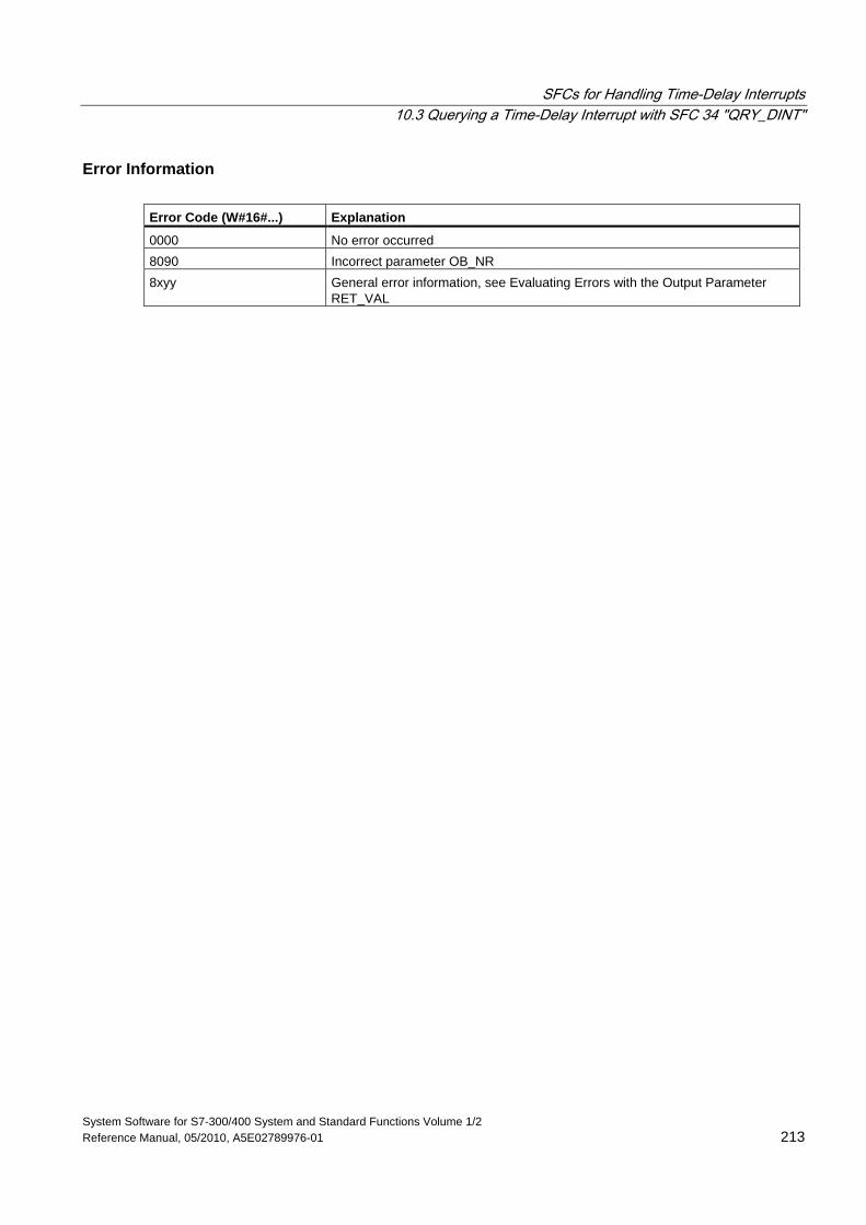
SFCs for Handling Time-Delay Interrupts 10.3 Querying a Time-Delay Interrupt with SFC 34 "QRY_DINT"
System Software for S7-300/400 System and Standard Functions Volume 1/2 Reference Manual, 05/2010, A5E02789976-01 213
Error Information Error Code (W#16#...) Explanation
0000 No error occurred 8090 Incorrect parameter OB_NR 8xyy General error information, see Evaluating Errors with the Output Parameter
RET_VAL
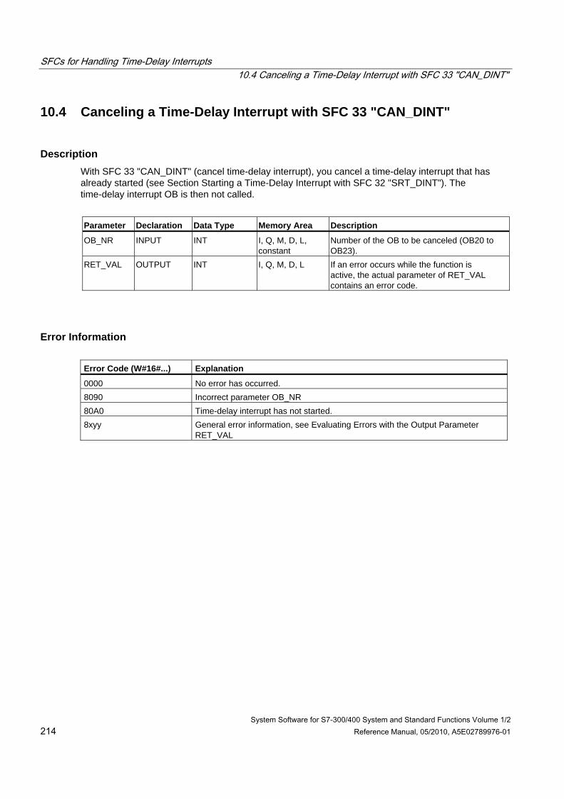
SFCs for Handling Time-Delay Interrupts 10.4 Canceling a Time-Delay Interrupt with SFC 33 "CAN_DINT"
System Software for S7-300/400 System and Standard Functions Volume 1/2 214 Reference Manual, 05/2010, A5E02789976-01
10.4 Canceling a Time-Delay Interrupt with SFC 33 "CAN_DINT"
Description With SFC 33 "CAN_DINT" (cancel time-delay interrupt), you cancel a time-delay interrupt that has already started (see Section Starting a Time-Delay Interrupt with SFC 32 "SRT_DINT"). The time-delay interrupt OB is then not called.
Parameter Declaration Data Type Memory Area Description
OB_NR INPUT INT I, Q, M, D, L, constant
Number of the OB to be canceled (OB20 to OB23).
RET_VAL OUTPUT INT I, Q, M, D, L If an error occurs while the function is active, the actual parameter of RET_VAL contains an error code.
Error Information Error Code (W#16#...) Explanation
0000 No error has occurred. 8090 Incorrect parameter OB_NR 80A0 Time-delay interrupt has not started. 8xyy General error information, see Evaluating Errors with the Output Parameter
RET_VAL
System Software for S7-300/400 System and Standard Functions Volume 1/2 Reference Manual, 05/2010, A5E02789976-01 215
11 SFCs for Handling Synchronous Errors
11.1 Masking Synchronous Errors
Introduction Synchronous errors are programming and access errors. Such errors occur as a result of programming with incorrect address areas, numbers, or incorrect addresses. Masking these synchronous errors means the following:
• Masked synchronous errors do not trigger an error OB call and do not lead to a programmed alternative reaction.
• The CPU "records" the masked errors that have occurred in an error register.
Masking is carried out by calling the SFC 36 "MSK_FLT".
Unmasking errors means canceling a previously set mask and clearing the corresponding bit in the event status register of the current priority class. Masking is canceled as follows:
• By calling SFC 37 "DMSK_FLT"
• When the current priority class has been completed (only for S7-400).
If an error occurs after it has been unmasked, the operating system starts the corresponding error OB. You can program OB121 for a reaction to programming errors and OB122 for a reaction to access errors.
You can use SFC 38 "READ_ERR" to read out the masked errors that have occurred.
Note: With the S7-300 (except CPU 318), regardless of whether an error is masked or unmasked, the error is entered in the diagnostic buffer and the group error LED of the CPU is lit.
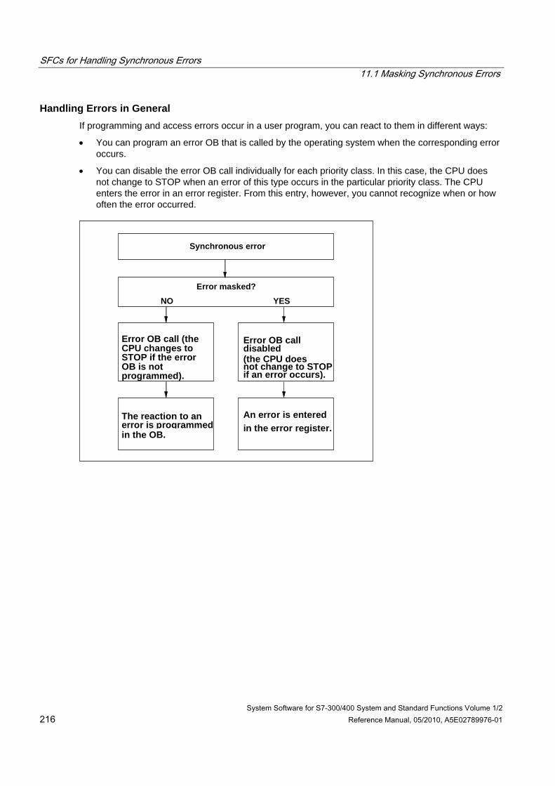
SFCs for Handling Synchronous Errors 11.1 Masking Synchronous Errors
System Software for S7-300/400 System and Standard Functions Volume 1/2 216 Reference Manual, 05/2010, A5E02789976-01
Handling Errors in General If programming and access errors occur in a user program, you can react to them in different ways:
• You can program an error OB that is called by the operating system when the corresponding error occurs.
• You can disable the error OB call individually for each priority class. In this case, the CPU does not change to STOP when an error of this type occurs in the particular priority class. The CPU enters the error in an error register. From this entry, however, you cannot recognize when or how often the error occurred.
Error masked?
Synchronous error
NO YES
The reaction to anerror is programmedin the OB.
An error is enteredin the error register.
Error OB call (theCPU changes toSTOP if the errorOB is notprogrammed).
Error OB call
(the CPU doesnot change to STOPif an error occurs).
disabled
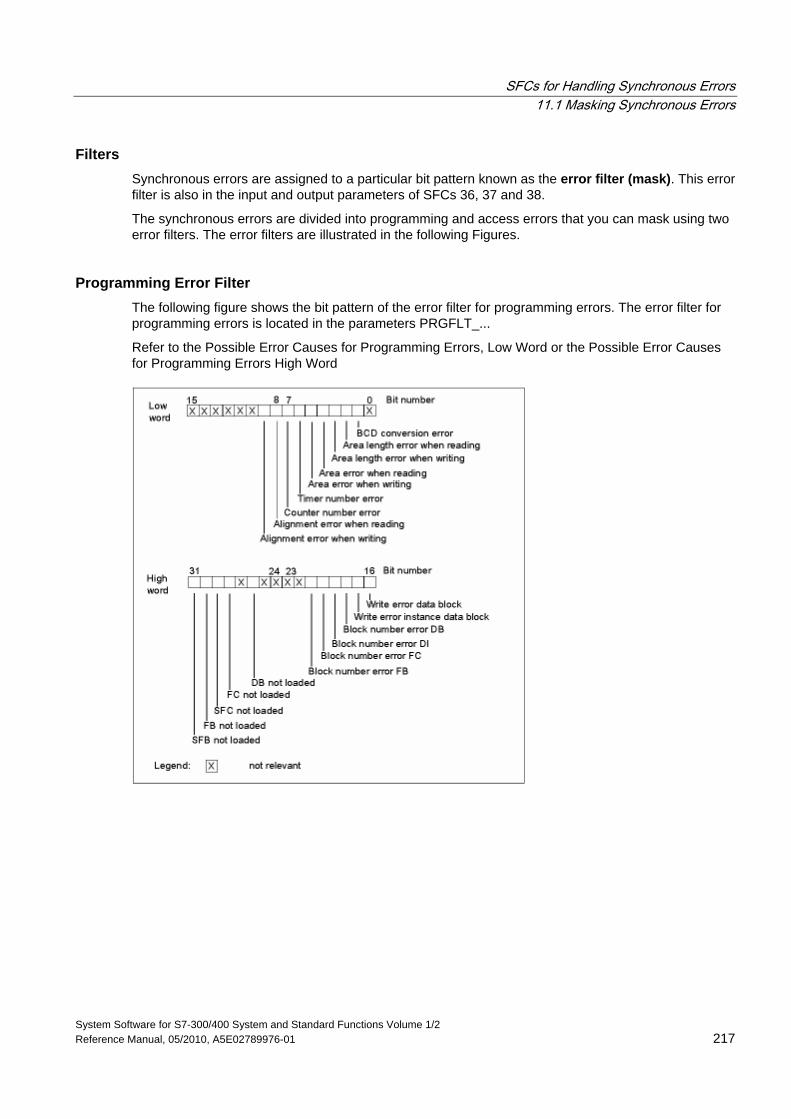
SFCs for Handling Synchronous Errors 11.1 Masking Synchronous Errors
System Software for S7-300/400 System and Standard Functions Volume 1/2 Reference Manual, 05/2010, A5E02789976-01 217
Filters Synchronous errors are assigned to a particular bit pattern known as the error filter (mask). This error filter is also in the input and output parameters of SFCs 36, 37 and 38.
The synchronous errors are divided into programming and access errors that you can mask using two error filters. The error filters are illustrated in the following Figures.
Programming Error Filter The following figure shows the bit pattern of the error filter for programming errors. The error filter for programming errors is located in the parameters PRGFLT_...
Refer to the Possible Error Causes for Programming Errors, Low Word or the Possible Error Causes for Programming Errors High Word
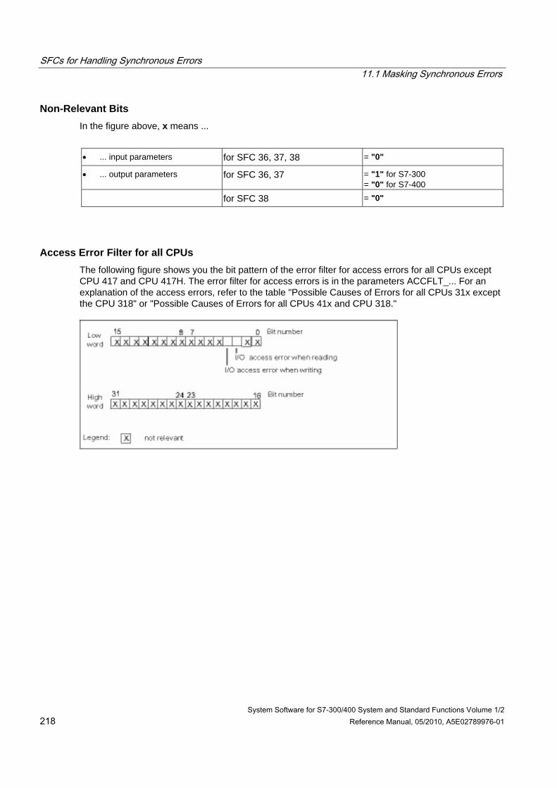
SFCs for Handling Synchronous Errors 11.1 Masking Synchronous Errors
System Software for S7-300/400 System and Standard Functions Volume 1/2 218 Reference Manual, 05/2010, A5E02789976-01
Non-Relevant Bits In the figure above, x means ...
• ... input parameters for SFC 36, 37, 38 = "0"
• ... output parameters for SFC 36, 37 = "1" for S7-300 = "0" for S7-400
for SFC 38 = "0"
Access Error Filter for all CPUs The following figure shows you the bit pattern of the error filter for access errors for all CPUs except CPU 417 and CPU 417H. The error filter for access errors is in the parameters ACCFLT_... For an explanation of the access errors, refer to the table "Possible Causes of Errors for all CPUs 31x except the CPU 318" or "Possible Causes of Errors for all CPUs 41x and CPU 318."
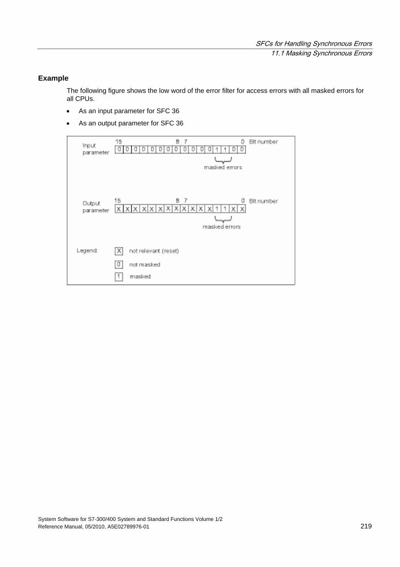
SFCs for Handling Synchronous Errors 11.1 Masking Synchronous Errors
System Software for S7-300/400 System and Standard Functions Volume 1/2 Reference Manual, 05/2010, A5E02789976-01 219
Example The following figure shows the low word of the error filter for access errors with all masked errors for all CPUs.
• As an input parameter for SFC 36
• As an output parameter for SFC 36
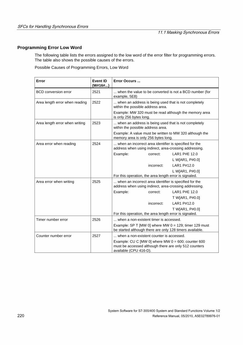
SFCs for Handling Synchronous Errors 11.1 Masking Synchronous Errors
System Software for S7-300/400 System and Standard Functions Volume 1/2 220 Reference Manual, 05/2010, A5E02789976-01
Programming Error Low Word The following table lists the errors assigned to the low word of the error filter for programming errors. The table also shows the possible causes of the errors.
Possible Causes of Programming Errors, Low Word
Error
Event ID (W#16#...)
Error Occurs ...
BCD conversion error 2521 ... when the value to be converted is not a BCD number (for example, 5E8)
Area length error when reading 2522 ... when an address is being used that is not completely within the possible address area. Example: MW 320 must be read although the memory area is only 256 bytes long.
Area length error when writing 2523 ... when an address is being used that is not completely within the possible address area. Example: A value must be written to MW 320 although the memory area is only 256 bytes long.
Area error when reading 2524 ... when an incorrect area identifier is specified for the address when using indirect, area-crossing addressing. Example: correct: LAR1 P#E 12.0 L W[AR1, P#0.0] incorrect: LAR1 P#12.0 L W[AR1, P#0.0] For this operation, the area length error is signaled.
Area error when writing 2525 ... when an incorrect area identifier is specified for the address when using indirect, area-crossing addressing. Example: correct: LAR1 P#E 12.0 T W[AR1, P#0.0] incorrect: LAR1 P#12.0 T W[AR1, P#0.0] For this operation, the area length error is signaled.
Timer number error 2526 ... when a non-existent timer is accessed. Example: SP T [MW 0] where MW 0 = 129; timer 129 must be started although there are only 128 timers available.
Counter number error 2527 ... when a non-existent counter is accessed. Example: CU C [MW 0] where MW 0 = 600; counter 600 must be accessed although there are only 512 counters available (CPU 416-D).
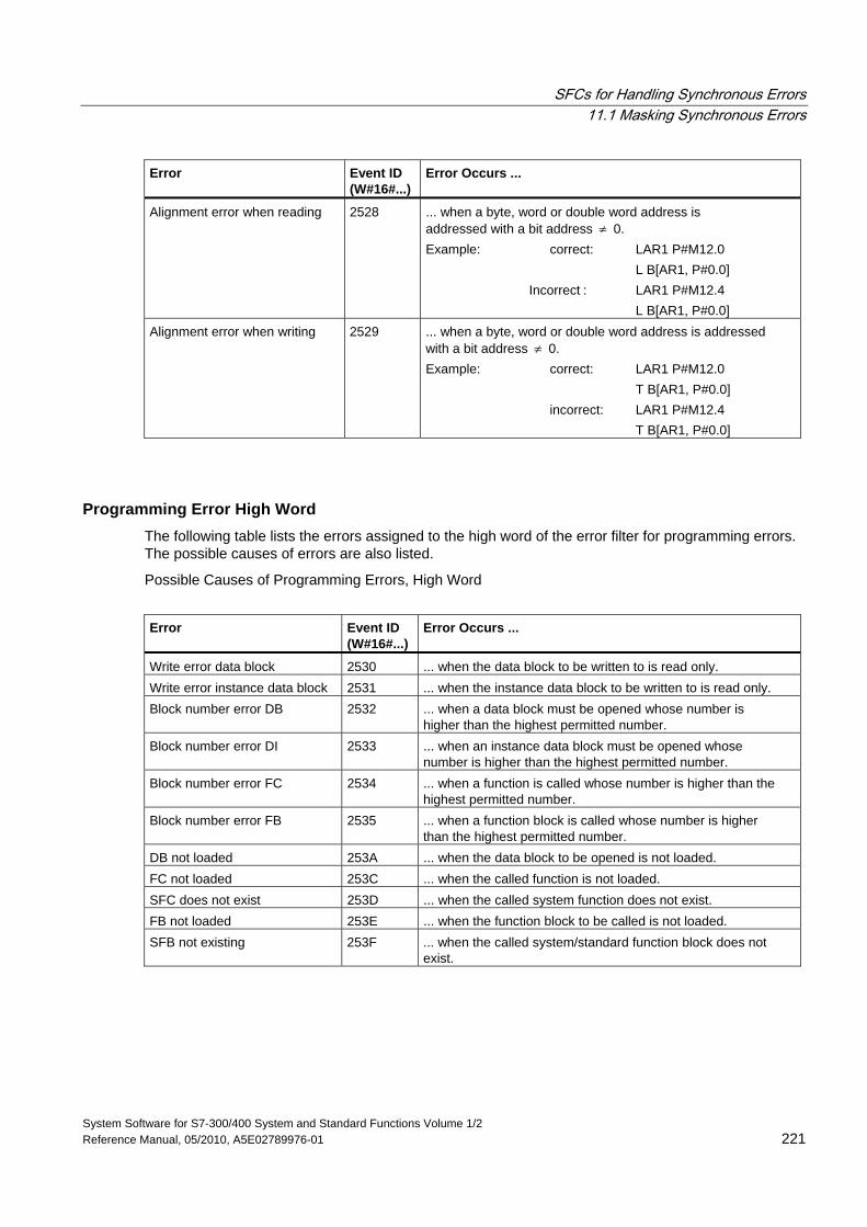
SFCs for Handling Synchronous Errors 11.1 Masking Synchronous Errors
System Software for S7-300/400 System and Standard Functions Volume 1/2 Reference Manual, 05/2010, A5E02789976-01 221
Error
Event ID (W#16#...)
Error Occurs ...
Alignment error when reading 2528 ... when a byte, word or double word address is addressed with a bit address ≠ 0. Example: correct: LAR1 P#M12.0 L B[AR1, P#0.0] Incorrect : LAR1 P#M12.4 L B[AR1, P#0.0]
Alignment error when writing 2529 ... when a byte, word or double word address is addressed with a bit address ≠ 0. Example: correct: LAR1 P#M12.0 T B[AR1, P#0.0] incorrect: LAR1 P#M12.4 T B[AR1, P#0.0]
Programming Error High Word The following table lists the errors assigned to the high word of the error filter for programming errors. The possible causes of errors are also listed.
Possible Causes of Programming Errors, High Word
Error
Event ID (W#16#...)
Error Occurs ...
Write error data block 2530 ... when the data block to be written to is read only. Write error instance data block 2531 ... when the instance data block to be written to is read only. Block number error DB 2532 ... when a data block must be opened whose number is
higher than the highest permitted number. Block number error DI 2533 ... when an instance data block must be opened whose
number is higher than the highest permitted number. Block number error FC 2534 ... when a function is called whose number is higher than the
highest permitted number. Block number error FB 2535 ... when a function block is called whose number is higher
than the highest permitted number. DB not loaded 253A ... when the data block to be opened is not loaded. FC not loaded 253C ... when the called function is not loaded. SFC does not exist 253D ... when the called system function does not exist. FB not loaded 253E ... when the function block to be called is not loaded. SFB not existing 253F ... when the called system/standard function block does not
exist.
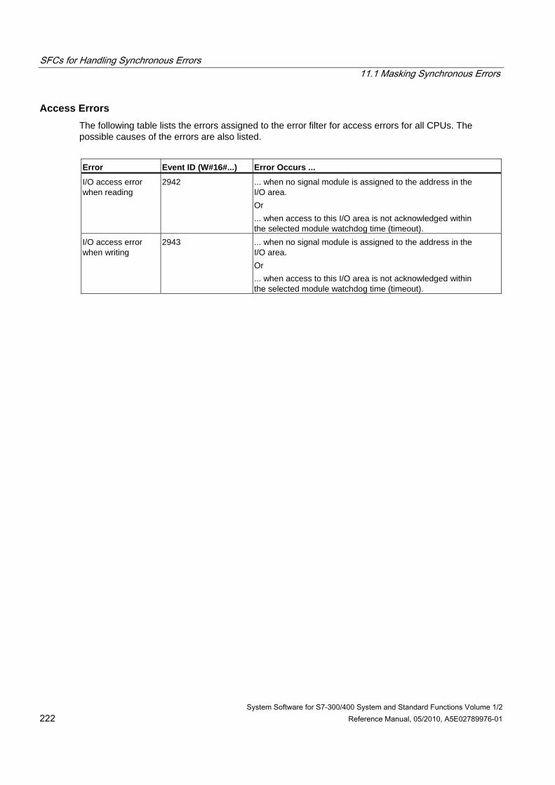
SFCs for Handling Synchronous Errors 11.1 Masking Synchronous Errors
System Software for S7-300/400 System and Standard Functions Volume 1/2 222 Reference Manual, 05/2010, A5E02789976-01
Access Errors The following table lists the errors assigned to the error filter for access errors for all CPUs. The possible causes of the errors are also listed.
Error Event ID (W#16#...) Error Occurs ...
I/O access error when reading
2942 ... when no signal module is assigned to the address in the I/O area. Or ... when access to this I/O area is not acknowledged within the selected module watchdog time (timeout).
I/O access error when writing
2943 ... when no signal module is assigned to the address in the I/O area. Or ... when access to this I/O area is not acknowledged within the selected module watchdog time (timeout).
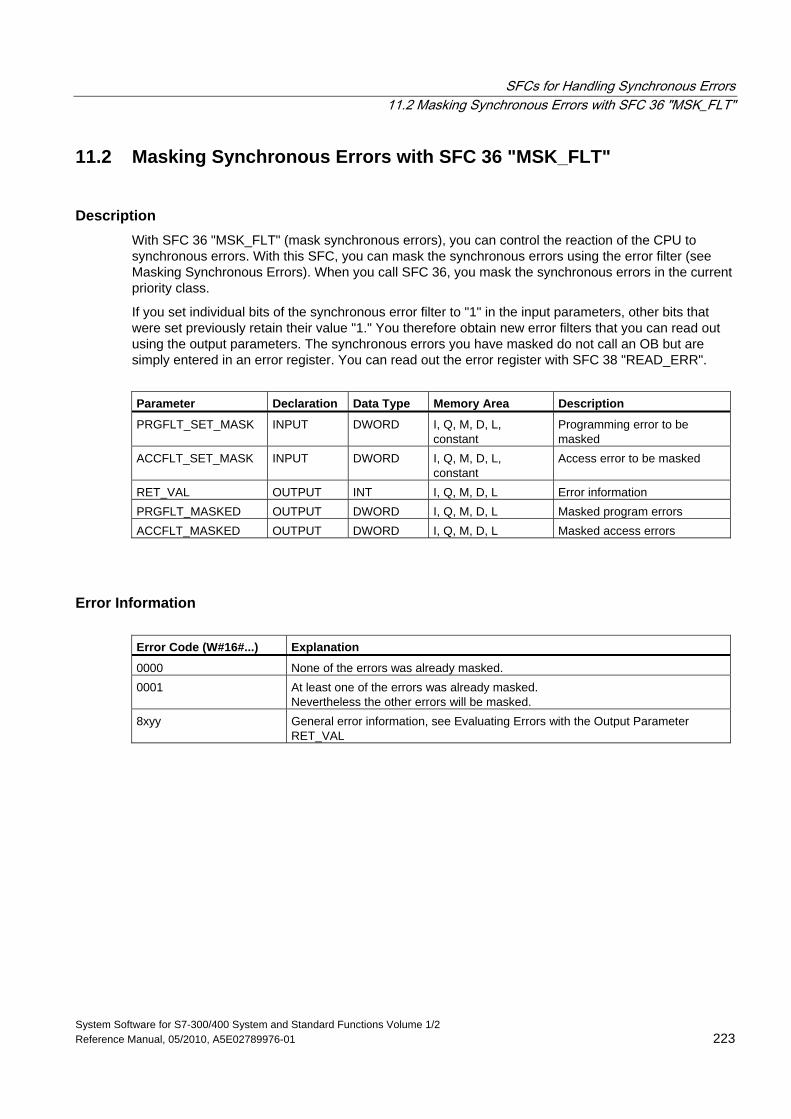
SFCs for Handling Synchronous Errors 11.2 Masking Synchronous Errors with SFC 36 "MSK_FLT"
System Software for S7-300/400 System and Standard Functions Volume 1/2 Reference Manual, 05/2010, A5E02789976-01 223
11.2 Masking Synchronous Errors with SFC 36 "MSK_FLT"
Description With SFC 36 "MSK_FLT" (mask synchronous errors), you can control the reaction of the CPU to synchronous errors. With this SFC, you can mask the synchronous errors using the error filter (see Masking Synchronous Errors). When you call SFC 36, you mask the synchronous errors in the current priority class.
If you set individual bits of the synchronous error filter to "1" in the input parameters, other bits that were set previously retain their value "1." You therefore obtain new error filters that you can read out using the output parameters. The synchronous errors you have masked do not call an OB but are simply entered in an error register. You can read out the error register with SFC 38 "READ_ERR".
Parameter Declaration Data Type Memory Area Description
PRGFLT_SET_MASK INPUT DWORD I, Q, M, D, L, constant
Programming error to be masked
ACCFLT_SET_MASK INPUT DWORD I, Q, M, D, L, constant
Access error to be masked
RET_VAL OUTPUT INT I, Q, M, D, L Error information PRGFLT_MASKED OUTPUT DWORD I, Q, M, D, L Masked program errors ACCFLT_MASKED OUTPUT DWORD I, Q, M, D, L Masked access errors
Error Information Error Code (W#16#...) Explanation
0000 None of the errors was already masked. 0001 At least one of the errors was already masked.
Nevertheless the other errors will be masked. 8xyy General error information, see Evaluating Errors with the Output Parameter
RET_VAL
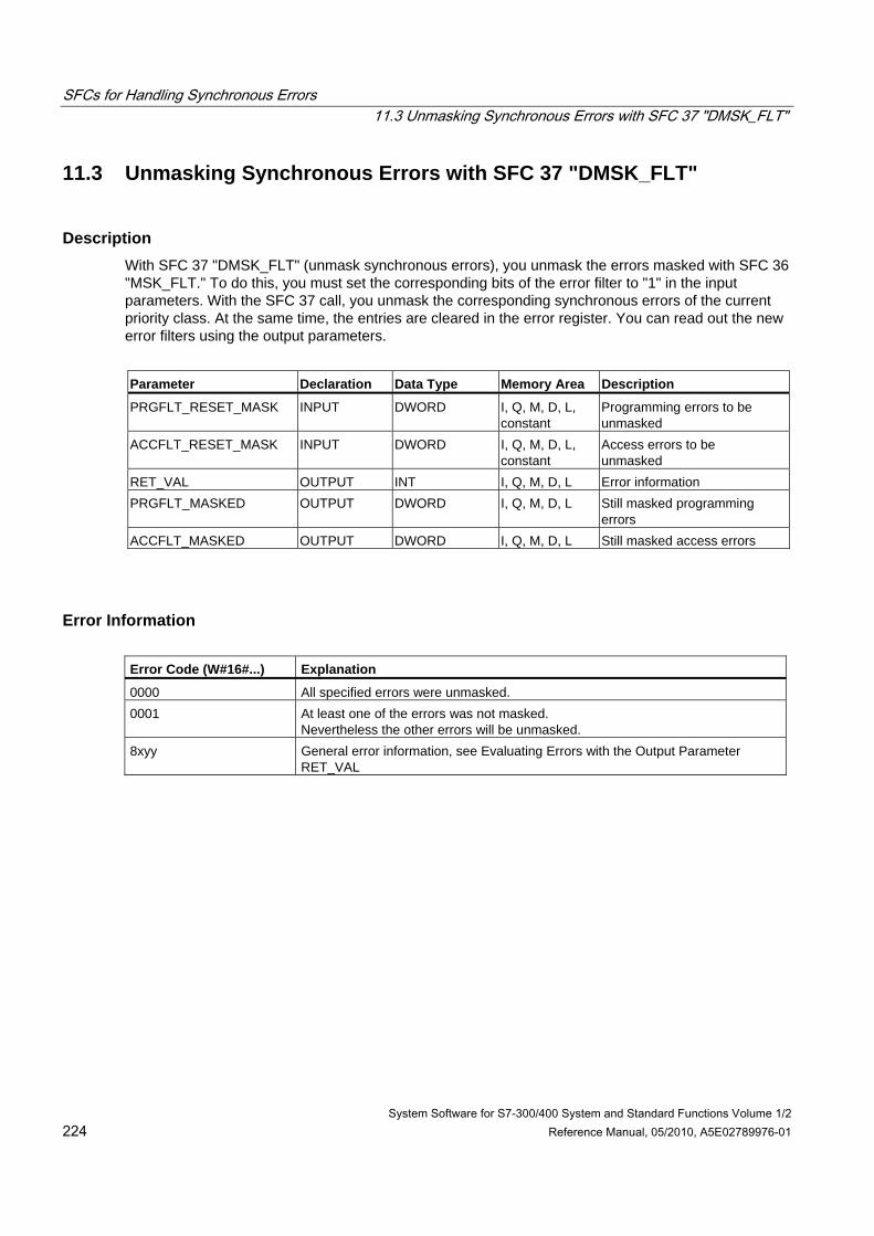
SFCs for Handling Synchronous Errors 11.3 Unmasking Synchronous Errors with SFC 37 "DMSK_FLT"
System Software for S7-300/400 System and Standard Functions Volume 1/2 224 Reference Manual, 05/2010, A5E02789976-01
11.3 Unmasking Synchronous Errors with SFC 37 "DMSK_FLT"
Description With SFC 37 "DMSK_FLT" (unmask synchronous errors), you unmask the errors masked with SFC 36 "MSK_FLT." To do this, you must set the corresponding bits of the error filter to "1" in the input parameters. With the SFC 37 call, you unmask the corresponding synchronous errors of the current priority class. At the same time, the entries are cleared in the error register. You can read out the new error filters using the output parameters.
Parameter Declaration Data Type Memory Area Description
PRGFLT_RESET_MASK INPUT DWORD I, Q, M, D, L, constant
Programming errors to be unmasked
ACCFLT_RESET_MASK INPUT DWORD I, Q, M, D, L, constant
Access errors to be unmasked
RET_VAL OUTPUT INT I, Q, M, D, L Error information PRGFLT_MASKED OUTPUT DWORD I, Q, M, D, L Still masked programming
errors ACCFLT_MASKED OUTPUT DWORD I, Q, M, D, L Still masked access errors
Error Information Error Code (W#16#...) Explanation
0000 All specified errors were unmasked. 0001 At least one of the errors was not masked.
Nevertheless the other errors will be unmasked. 8xyy General error information, see Evaluating Errors with the Output Parameter
RET_VAL
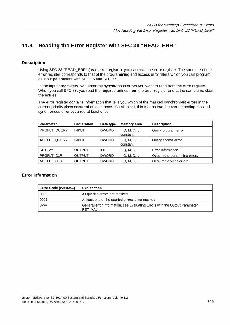
SFCs for Handling Synchronous Errors 11.4 Reading the Error Register with SFC 38 "READ_ERR"
System Software for S7-300/400 System and Standard Functions Volume 1/2 Reference Manual, 05/2010, A5E02789976-01 225
11.4 Reading the Error Register with SFC 38 "READ_ERR"
Description Using SFC 38 "READ_ERR" (read error register), you can read the error register. The structure of the error register corresponds to that of the programming and access error filters which you can program as input parameters with SFC 36 and SFC 37.
In the input parameters, you enter the synchronous errors you want to read from the error register. When you call SFC 38, you read the required entries from the error register and at the same time clear the entries.
The error register contains information that tells you which of the masked synchronous errors in the current priority class occurred at least once. If a bit is set, this means that the corresponding masked synchronous error occurred at least once.
Parameter Declaration Data type Memory area Description
PRGFLT_QUERY INPUT DWORD I, Q, M, D, L, constant
Query program error
ACCFLT_QUERY INPUT DWORD I, Q, M, D, L, constant
Query access error
RET_VAL OUTPUT INT I, Q, M, D, L Error Information PRGFLT_CLR OUTPUT DWORD I, Q, M, D, L Occurred programming errors ACCFLT_CLR OUTPUT DWORD I, Q, M, D, L Occurred access errors
Error Information Error Code (W#16#...) Explanation
0000 All queried errors are masked. 0001 At least one of the queried errors is not masked. 8xyy General error information, see Evaluating Errors with the Output Parameter
RET_VAL
SFCs for Handling Synchronous Errors 11.4 Reading the Error Register with SFC 38 "READ_ERR"
System Software for S7-300/400 System and Standard Functions Volume 1/2 226 Reference Manual, 05/2010, A5E02789976-01
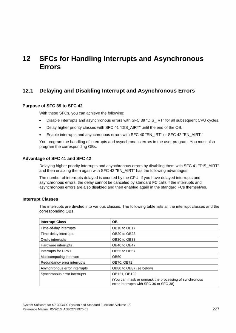
System Software for S7-300/400 System and Standard Functions Volume 1/2 Reference Manual, 05/2010, A5E02789976-01 227
12 SFCs for Handling Interrupts and Asynchronous Errors
12.1 Delaying and Disabling Interrupt and Asynchronous Errors
Purpose of SFC 39 to SFC 42 With these SFCs, you can achieve the following:
• Disable interrupts and asynchronous errors with SFC 39 "DIS_IRT" for all subsequent CPU cycles.
• Delay higher priority classes with SFC 41 "DIS_AIRT" until the end of the OB.
• Enable interrupts and asynchronous errors with SFC 40 "EN_IRT" or SFC 42 "EN_AIRT."
You program the handling of interrupts and asynchronous errors in the user program. You must also program the corresponding OBs.
Advantage of SFC 41 and SFC 42 Delaying higher priority interrupts and asynchronous errors by disabling them with SFC 41 "DIS_AIRT" and then enabling them again with SFC 42 "EN_AIRT" has the following advantages:
The number of interrupts delayed is counted by the CPU. If you have delayed interrupts and asynchronous errors, the delay cannot be canceled by standard FC calls if the interrupts and asynchronous errors are also disabled and then enabled again in the standard FCs themselves.
Interrupt Classes The interrupts are divided into various classes. The following table lists all the interrupt classes and the corresponding OBs. Interrupt Class OB
Time-of-day interrupts OB10 to OB17 Time-delay interrupts OB20 to OB23 Cyclic interrupts OB30 to OB38 Hardware interrupts OB40 to OB47 Interrupts for DPV1 OB55 to OB57 Multicomputing interrupt OB60 Redundancy error interrupts OB70, OB72 Asynchronous error interrupts OB80 to OB87 (se below) Synchronous error interrupts OB121, OB122
(You can mask or unmask the processing of synchronous error interrupts with SFC 36 to SFC 38)
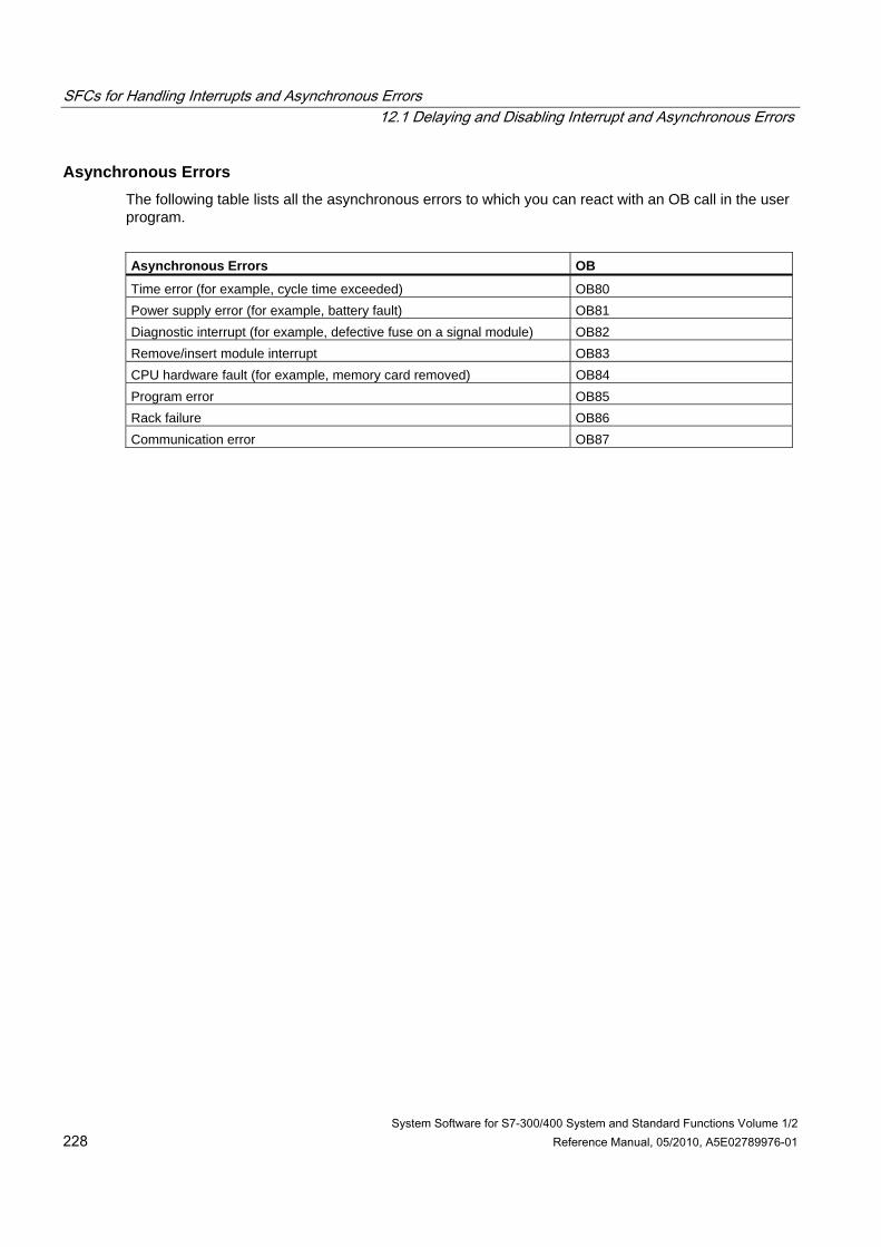
SFCs for Handling Interrupts and Asynchronous Errors 12.1 Delaying and Disabling Interrupt and Asynchronous Errors
System Software for S7-300/400 System and Standard Functions Volume 1/2 228 Reference Manual, 05/2010, A5E02789976-01
Asynchronous Errors The following table lists all the asynchronous errors to which you can react with an OB call in the user program.
Asynchronous Errors OB
Time error (for example, cycle time exceeded) OB80 Power supply error (for example, battery fault) OB81 Diagnostic interrupt (for example, defective fuse on a signal module) OB82 Remove/insert module interrupt OB83 CPU hardware fault (for example, memory card removed) OB84 Program error OB85 Rack failure OB86 Communication error OB87
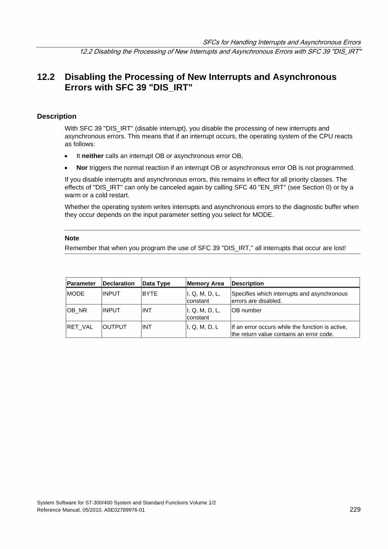
SFCs for Handling Interrupts and Asynchronous Errors 12.2 Disabling the Processing of New Interrupts and Asynchronous Errors with SFC 39 "DIS_IRT"
System Software for S7-300/400 System and Standard Functions Volume 1/2 Reference Manual, 05/2010, A5E02789976-01 229
12.2 Disabling the Processing of New Interrupts and Asynchronous Errors with SFC 39 "DIS_IRT"
Description With SFC 39 "DIS_IRT" (disable interrupt), you disable the processing of new interrupts and asynchronous errors. This means that if an interrupt occurs, the operating system of the CPU reacts as follows:
• It neither calls an interrupt OB or asynchronous error OB,
• Nor triggers the normal reaction if an interrupt OB or asynchronous error OB is not programmed.
If you disable interrupts and asynchronous errors, this remains in effect for all priority classes. The effects of "DIS_IRT" can only be canceled again by calling SFC 40 "EN_IRT" (see Section 0) or by a warm or a cold restart.
Whether the operating system writes interrupts and asynchronous errors to the diagnostic buffer when they occur depends on the input parameter setting you select for MODE.
Note
Remember that when you program the use of SFC 39 "DIS_IRT," all interrupts that occur are lost!
Parameter Declaration Data Type Memory Area Description
MODE INPUT BYTE I, Q, M, D, L, constant
Specifies which interrupts and asynchronous errors are disabled.
OB_NR INPUT INT I, Q, M, D, L, constant
OB number
RET_VAL OUTPUT INT I, Q, M, D, L If an error occurs while the function is active, the return value contains an error code.
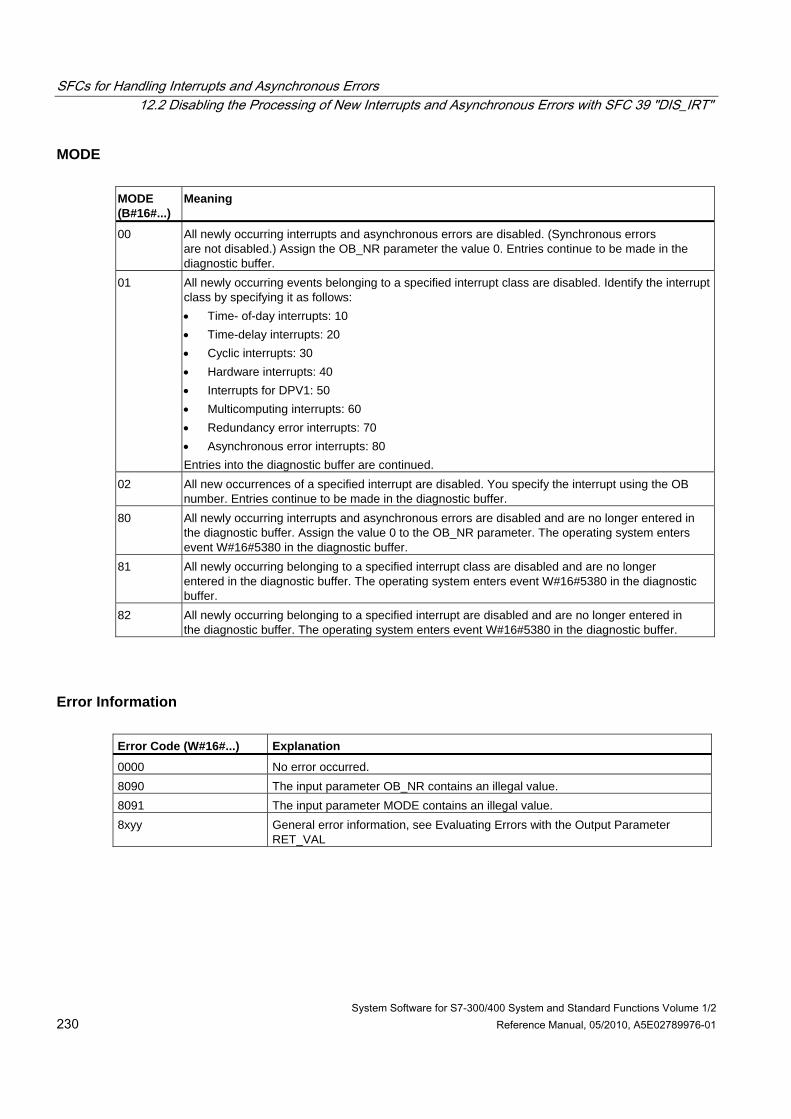
SFCs for Handling Interrupts and Asynchronous Errors 12.2 Disabling the Processing of New Interrupts and Asynchronous Errors with SFC 39 "DIS_IRT"
System Software for S7-300/400 System and Standard Functions Volume 1/2 230 Reference Manual, 05/2010, A5E02789976-01
MODE MODE (B#16#...)
Meaning
00 All newly occurring interrupts and asynchronous errors are disabled. (Synchronous errors are not disabled.) Assign the OB_NR parameter the value 0. Entries continue to be made in the diagnostic buffer.
01 All newly occurring events belonging to a specified interrupt class are disabled. Identify the interrupt class by specifying it as follows: • Time- of-day interrupts: 10 • Time-delay interrupts: 20 • Cyclic interrupts: 30 • Hardware interrupts: 40 • Interrupts for DPV1: 50 • Multicomputing interrupts: 60 • Redundancy error interrupts: 70 • Asynchronous error interrupts: 80 Entries into the diagnostic buffer are continued.
02 All new occurrences of a specified interrupt are disabled. You specify the interrupt using the OB number. Entries continue to be made in the diagnostic buffer.
80 All newly occurring interrupts and asynchronous errors are disabled and are no longer entered in the diagnostic buffer. Assign the value 0 to the OB_NR parameter. The operating system enters event W#16#5380 in the diagnostic buffer.
81 All newly occurring belonging to a specified interrupt class are disabled and are no longer entered in the diagnostic buffer. The operating system enters event W#16#5380 in the diagnostic buffer.
82 All newly occurring belonging to a specified interrupt are disabled and are no longer entered in the diagnostic buffer. The operating system enters event W#16#5380 in the diagnostic buffer.
Error Information Error Code (W#16#...) Explanation
0000 No error occurred. 8090 The input parameter OB_NR contains an illegal value. 8091 The input parameter MODE contains an illegal value. 8xyy General error information, see Evaluating Errors with the Output Parameter
RET_VAL
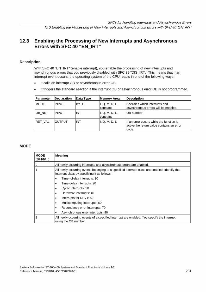
SFCs for Handling Interrupts and Asynchronous Errors 12.3 Enabling the Processing of New Interrupts and Asynchronous Errors with SFC 40 "EN_IRT"
System Software for S7-300/400 System and Standard Functions Volume 1/2 Reference Manual, 05/2010, A5E02789976-01 231
12.3 Enabling the Processing of New Interrupts and Asynchronous Errors with SFC 40 "EN_IRT"
Description With SFC 40 "EN_IRT" (enable interrupt), you enable the processing of new interrupts and asynchronous errors that you previously disabled with SFC 39 "DIS_IRT." This means that if an interrupt event occurs, the operating system of the CPU reacts in one of the following ways:
• It calls an interrupt OB or asynchronous error OB.
• It triggers the standard reaction if the interrupt OB or asynchronous error OB is not programmed. Parameter Declaration Data Type Memory Area Description
MODE INPUT BYTE I, Q, M, D, L, constant
Specifies which interrupts and asynchronous errors will be enabled.
OB_NR INPUT INT I, Q, M, D, L, constant
OB number
RET_VAL OUTPUT INT I, Q, M, D, L If an error occurs while the function is active the return value contains an error code.
MODE MODE (B#16#...)
Meaning
0 All newly occurring interrupts and asynchronous errors are enabled. 1 All newly occurring events belonging to a specified interrupt class are enabled. Identify the
interrupt class by specifying it as follows: • Time- of-day interrupts: 10 • Time-delay interrupts: 20 • Cyclic interrupts: 30 • Hardware interrupts: 40 • Interrupts for DPV1: 50 • Multicomputing interrupts: 60 • Redundancy error interrupts: 70 • Asynchronous error interrupts: 80
2 All newly occurring events of a specified interrupt are enabled. You specify the interrupt using the OB number.
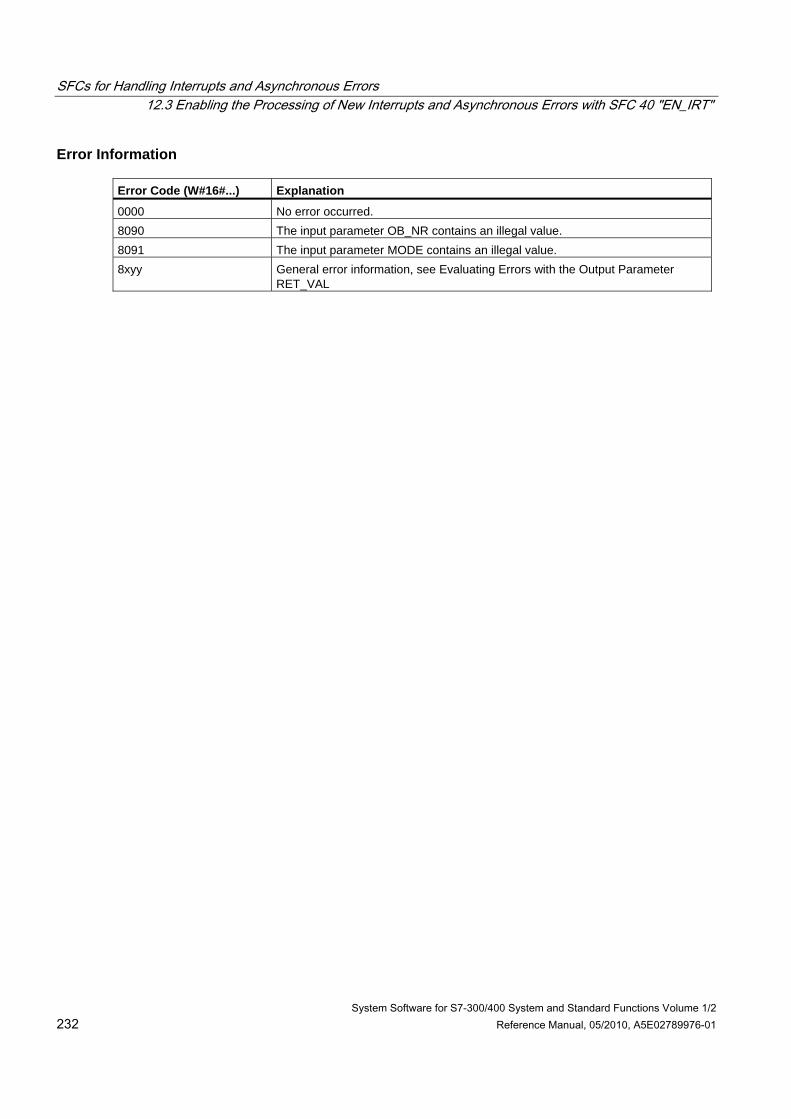
SFCs for Handling Interrupts and Asynchronous Errors 12.3 Enabling the Processing of New Interrupts and Asynchronous Errors with SFC 40 "EN_IRT"
System Software for S7-300/400 System and Standard Functions Volume 1/2 232 Reference Manual, 05/2010, A5E02789976-01
Error Information Error Code (W#16#...) Explanation
0000 No error occurred. 8090 The input parameter OB_NR contains an illegal value. 8091 The input parameter MODE contains an illegal value. 8xyy General error information, see Evaluating Errors with the Output Parameter
RET_VAL
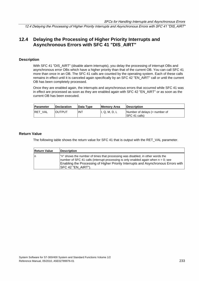
SFCs for Handling Interrupts and Asynchronous Errors 12.4 Delaying the Processing of Higher Priority Interrupts and Asynchronous Errors with SFC 41 "DIS_AIRT"
System Software for S7-300/400 System and Standard Functions Volume 1/2 Reference Manual, 05/2010, A5E02789976-01 233
12.4 Delaying the Processing of Higher Priority Interrupts and Asynchronous Errors with SFC 41 "DIS_AIRT"
Description With SFC 41 "DIS_AIRT" (disable alarm interrupts), you delay the processing of interrupt OBs and asynchronous error OBs which have a higher priority than that of the current OB. You can call SFC 41 more than once in an OB. The SFC 41 calls are counted by the operating system. Each of these calls remains in effect until it is canceled again specifically by an SFC 42 "EN_AIRT" call or until the current OB has been completely processed.
Once they are enabled again, the interrupts and asynchronous errors that occurred while SFC 41 was in effect are processed as soon as they are enabled again with SFC 42 "EN_AIRT" or as soon as the current OB has been executed.
Parameter Declaration Data Type Memory Area Description
RET_VAL OUTPUT INT I, Q, M, D, L Number of delays (= number of SFC 41 calls)
Return Value The following table shows the return value for SFC 41 that is output with the RET_VAL parameter.
Return Value Description
n "n" shows the number of times that processing was disabled, in other words the number of SFC 41 calls (interrupt processing is only enabled again when n = 0; see Enabling the Processing of Higher Priority Interrupts and Asynchronous Errors with SFC 42 "EN_AIRT").
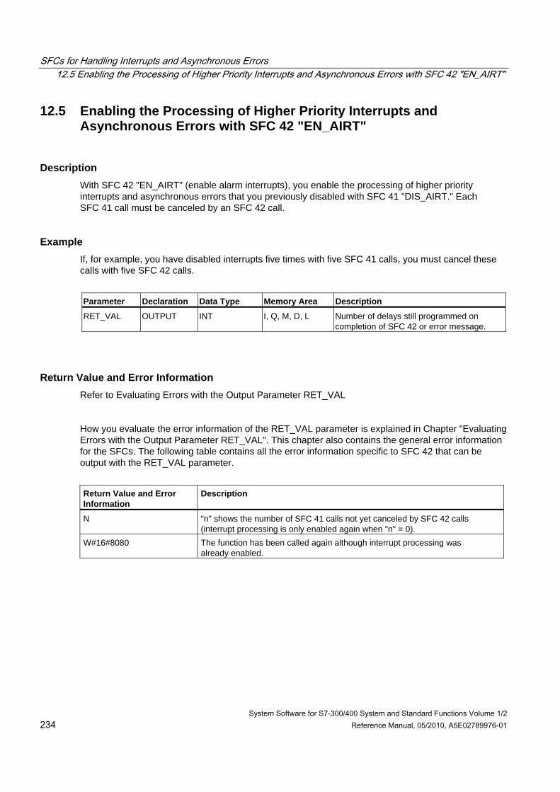
SFCs for Handling Interrupts and Asynchronous Errors 12.5 Enabling the Processing of Higher Priority Interrupts and Asynchronous Errors with SFC 42 "EN_AIRT"
System Software for S7-300/400 System and Standard Functions Volume 1/2 234 Reference Manual, 05/2010, A5E02789976-01
12.5 Enabling the Processing of Higher Priority Interrupts and Asynchronous Errors with SFC 42 "EN_AIRT"
Description With SFC 42 "EN_AIRT" (enable alarm interrupts), you enable the processing of higher priority interrupts and asynchronous errors that you previously disabled with SFC 41 "DIS_AIRT." Each SFC 41 call must be canceled by an SFC 42 call.
Example If, for example, you have disabled interrupts five times with five SFC 41 calls, you must cancel these calls with five SFC 42 calls.
Parameter Declaration Data Type Memory Area Description
RET_VAL OUTPUT INT I, Q, M, D, L Number of delays still programmed on completion of SFC 42 or error message.
Return Value and Error Information Refer to Evaluating Errors with the Output Parameter RET_VAL
How you evaluate the error information of the RET_VAL parameter is explained in Chapter "Evaluating Errors with the Output Parameter RET_VAL". This chapter also contains the general error information for the SFCs. The following table contains all the error information specific to SFC 42 that can be output with the RET_VAL parameter.
Return Value and Error Information
Description
N "n" shows the number of SFC 41 calls not yet canceled by SFC 42 calls (interrupt processing is only enabled again when "n" = 0).
W#16#8080 The function has been called again although interrupt processing was already enabled.
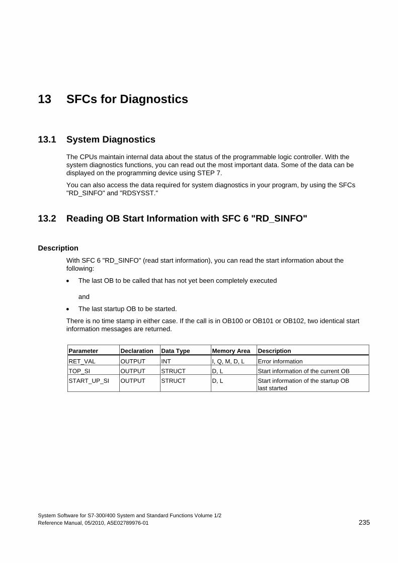
System Software for S7-300/400 System and Standard Functions Volume 1/2 Reference Manual, 05/2010, A5E02789976-01 235
13 SFCs for Diagnostics
13.1 System Diagnostics
The CPUs maintain internal data about the status of the programmable logic controller. With the system diagnostics functions, you can read out the most important data. Some of the data can be displayed on the programming device using STEP 7.
You can also access the data required for system diagnostics in your program, by using the SFCs "RD_SINFO" and "RDSYSST."
13.2 Reading OB Start Information with SFC 6 "RD_SINFO"
Description With SFC 6 "RD_SINFO" (read start information), you can read the start information about the following:
• The last OB to be called that has not yet been completely executed and
• The last startup OB to be started.
There is no time stamp in either case. If the call is in OB100 or OB101 or OB102, two identical start information messages are returned.
Parameter Declaration Data Type Memory Area Description
RET_VAL OUTPUT INT I, Q, M, D, L Error information TOP_SI OUTPUT STRUCT D, L Start information of the current OB START_UP_SI OUTPUT STRUCT D, L Start information of the startup OB
last started
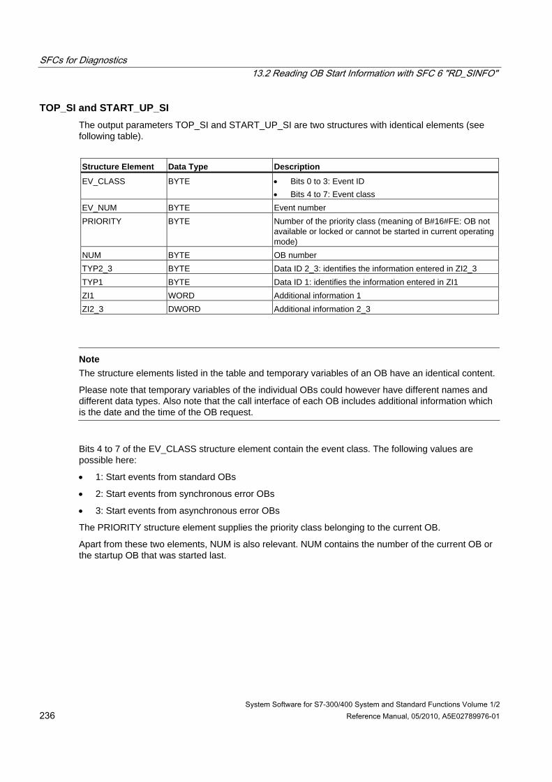
SFCs for Diagnostics 13.2 Reading OB Start Information with SFC 6 "RD_SINFO"
System Software for S7-300/400 System and Standard Functions Volume 1/2 236 Reference Manual, 05/2010, A5E02789976-01
TOP_SI and START_UP_SI The output parameters TOP_SI and START_UP_SI are two structures with identical elements (see following table).
Structure Element Data Type Description
EV_CLASS BYTE • Bits 0 to 3: Event ID • Bits 4 to 7: Event class
EV_NUM BYTE Event number PRIORITY BYTE Number of the priority class (meaning of B#16#FE: OB not
available or locked or cannot be started in current operating mode)
NUM BYTE OB number TYP2_3 BYTE Data ID 2_3: identifies the information entered in ZI2_3 TYP1 BYTE Data ID 1: identifies the information entered in ZI1 ZI1 WORD Additional information 1 ZI2_3 DWORD Additional information 2_3
Note
The structure elements listed in the table and temporary variables of an OB have an identical content.
Please note that temporary variables of the individual OBs could however have different names and different data types. Also note that the call interface of each OB includes additional information which is the date and the time of the OB request.
Bits 4 to 7 of the EV_CLASS structure element contain the event class. The following values are possible here:
• 1: Start events from standard OBs
• 2: Start events from synchronous error OBs
• 3: Start events from asynchronous error OBs
The PRIORITY structure element supplies the priority class belonging to the current OB.
Apart from these two elements, NUM is also relevant. NUM contains the number of the current OB or the startup OB that was started last.
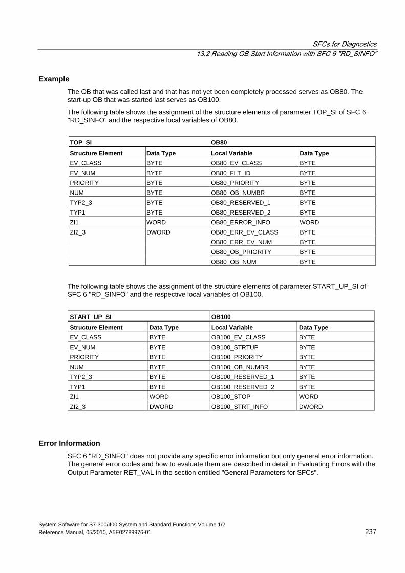
SFCs for Diagnostics 13.2 Reading OB Start Information with SFC 6 "RD_SINFO"
System Software for S7-300/400 System and Standard Functions Volume 1/2 Reference Manual, 05/2010, A5E02789976-01 237
Example The OB that was called last and that has not yet been completely processed serves as OB80. The start-up OB that was started last serves as OB100.
The following table shows the assignment of the structure elements of parameter TOP_SI of SFC 6 "RD_SINFO" and the respective local variables of OB80.
TOP_SI OB80
Structure Element Data Type Local Variable Data Type EV_CLASS BYTE OB80_EV_CLASS BYTE EV_NUM BYTE OB80_FLT_ID BYTE PRIORITY BYTE OB80_PRIORITY BYTE NUM BYTE OB80_OB_NUMBR BYTE TYP2_3 BYTE OB80_RESERVED_1 BYTE TYP1 BYTE OB80_RESERVED_2 BYTE ZI1 WORD OB80_ERROR_INFO WORD
OB80_ERR_EV_CLASS BYTE OB80_ERR_EV_NUM BYTE OB80_OB_PRIORITY BYTE
ZI2_3 DWORD
OB80_OB_NUM BYTE
The following table shows the assignment of the structure elements of parameter START_UP_SI of SFC 6 "RD_SINFO" and the respective local variables of OB100.
START_UP_SI OB100
Structure Element Data Type Local Variable Data Type EV_CLASS BYTE OB100_EV_CLASS BYTE EV_NUM BYTE OB100_STRTUP BYTE PRIORITY BYTE OB100_PRIORITY BYTE NUM BYTE OB100_OB_NUMBR BYTE TYP2_3 BYTE OB100_RESERVED_1 BYTE TYP1 BYTE OB100_RESERVED_2 BYTE ZI1 WORD OB100_STOP WORD ZI2_3 DWORD OB100_STRT_INFO DWORD
Error Information SFC 6 "RD_SINFO" does not provide any specific error information but only general error information. The general error codes and how to evaluate them are described in detail in Evaluating Errors with the Output Parameter RET_VAL in the section entitled "General Parameters for SFCs".
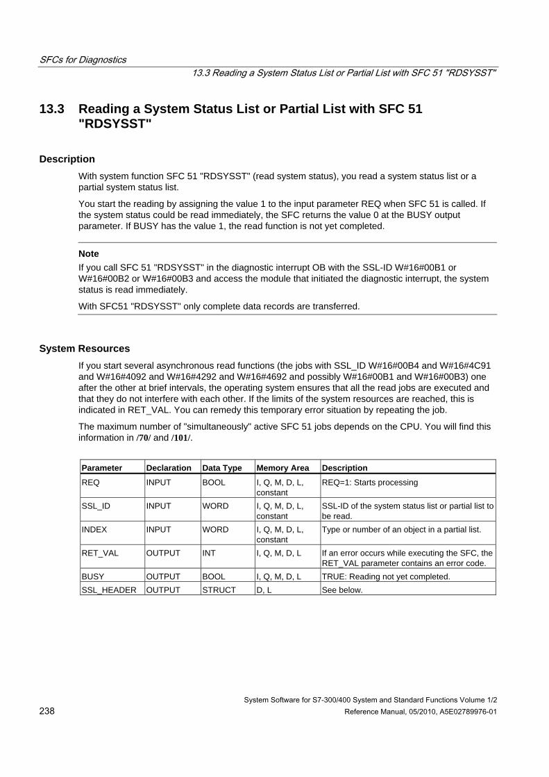
SFCs for Diagnostics 13.3 Reading a System Status List or Partial List with SFC 51 "RDSYSST"
System Software for S7-300/400 System and Standard Functions Volume 1/2 238 Reference Manual, 05/2010, A5E02789976-01
13.3 Reading a System Status List or Partial List with SFC 51 "RDSYSST"
Description With system function SFC 51 "RDSYSST" (read system status), you read a system status list or a partial system status list.
You start the reading by assigning the value 1 to the input parameter REQ when SFC 51 is called. If the system status could be read immediately, the SFC returns the value 0 at the BUSY output parameter. If BUSY has the value 1, the read function is not yet completed.
Note If you call SFC 51 "RDSYSST" in the diagnostic interrupt OB with the SSL-ID W#16#00B1 or W#16#00B2 or W#16#00B3 and access the module that initiated the diagnostic interrupt, the system status is read immediately.
With SFC51 "RDSYSST" only complete data records are transferred.
System Resources If you start several asynchronous read functions (the jobs with SSL_ID W#16#00B4 and W#16#4C91 and W#16#4092 and W#16#4292 and W#16#4692 and possibly W#16#00B1 and W#16#00B3) one after the other at brief intervals, the operating system ensures that all the read jobs are executed and that they do not interfere with each other. If the limits of the system resources are reached, this is indicated in RET_VAL. You can remedy this temporary error situation by repeating the job.
The maximum number of "simultaneously" active SFC 51 jobs depends on the CPU. You will find this information in /70/ and /101/.
Parameter Declaration Data Type Memory Area Description
REQ INPUT BOOL I, Q, M, D, L, constant
REQ=1: Starts processing
SSL_ID INPUT WORD I, Q, M, D, L, constant
SSL-ID of the system status list or partial list to be read.
INDEX INPUT WORD I, Q, M, D, L, constant
Type or number of an object in a partial list.
RET_VAL OUTPUT INT I, Q, M, D, L If an error occurs while executing the SFC, the RET_VAL parameter contains an error code.
BUSY OUTPUT BOOL I, Q, M, D, L TRUE: Reading not yet completed. SSL_HEADER OUTPUT STRUCT D, L See below.
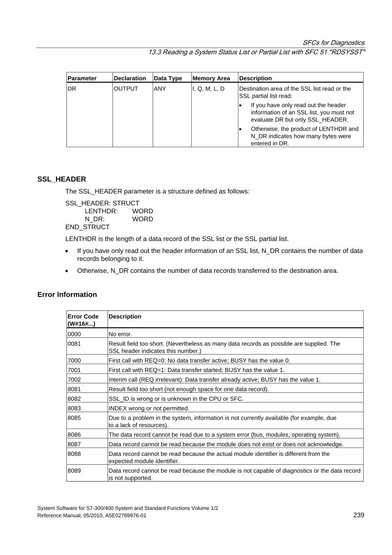
SFCs for Diagnostics 13.3 Reading a System Status List or Partial List with SFC 51 "RDSYSST"
System Software for S7-300/400 System and Standard Functions Volume 1/2 Reference Manual, 05/2010, A5E02789976-01 239
Parameter Declaration Data Type Memory Area Description
DR OUTPUT ANY I, Q, M, L, D Destination area of the SSL list read or the SSL partial list read: • If you have only read out the header
information of an SSL list, you must not evaluate DR but only SSL_HEADER.
• Otherwise, the product of LENTHDR and N_DR indicates how many bytes were entered in DR.
SSL_HEADER The SSL_HEADER parameter is a structure defined as follows:
SSL_HEADER: STRUCT LENTHDR: WORD N_DR: WORD END_STRUCT
LENTHDR is the length of a data record of the SSL list or the SSL partial list.
• If you have only read out the header information of an SSL list, N_DR contains the number of data records belonging to it.
• Otherwise, N_DR contains the number of data records transferred to the destination area.
Error Information Error Code (W#16#...)
Description
0000 No error. 0081 Result field too short. (Nevertheless as many data records as possible are supplied. The
SSL header indicates this number.) 7000 First call with REQ=0: No data transfer active; BUSY has the value 0. 7001 First call with REQ=1: Data transfer started; BUSY has the value 1. 7002 Interim call (REQ irrelevant): Data transfer already active; BUSY has the value 1. 8081 Result field too short (not enough space for one data record). 8082 SSL_ID is wrong or is unknown in the CPU or SFC. 8083 INDEX wrong or not permitted. 8085 Due to a problem in the system, information is not currently available (for example, due
to a lack of resources). 8086 The data record cannot be read due to a system error (bus, modules, operating system). 8087 Data record cannot be read because the module does not exist or does not acknowledge. 8088 Data record cannot be read because the actual module identifier is different from the
expected module identifier. 8089 Data record cannot be read because the module is not capable of diagnostics or the data record
is not supported.
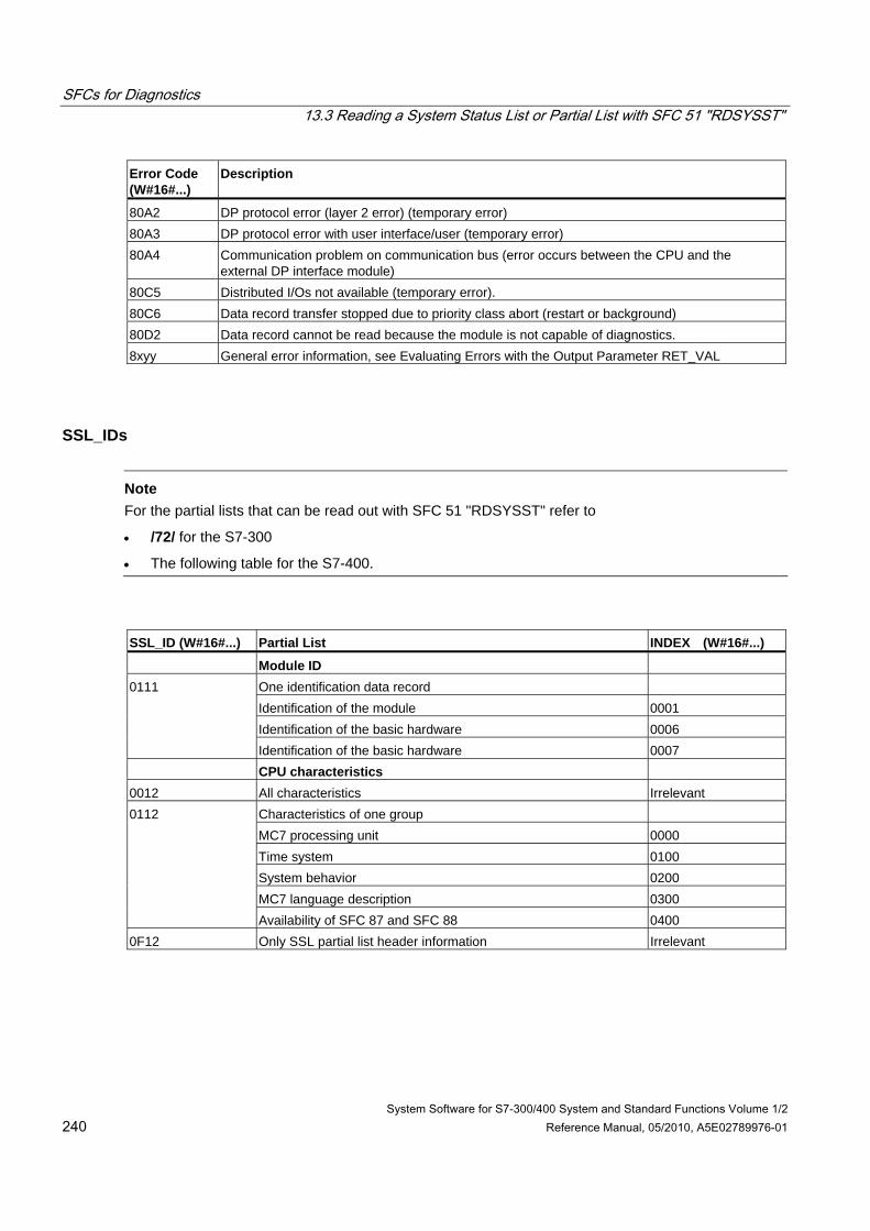
SFCs for Diagnostics 13.3 Reading a System Status List or Partial List with SFC 51 "RDSYSST"
System Software for S7-300/400 System and Standard Functions Volume 1/2 240 Reference Manual, 05/2010, A5E02789976-01
Error Code (W#16#...)
Description
80A2 DP protocol error (layer 2 error) (temporary error) 80A3 DP protocol error with user interface/user (temporary error) 80A4 Communication problem on communication bus (error occurs between the CPU and the
external DP interface module) 80C5 Distributed I/Os not available (temporary error). 80C6 Data record transfer stopped due to priority class abort (restart or background) 80D2 Data record cannot be read because the module is not capable of diagnostics. 8xyy General error information, see Evaluating Errors with the Output Parameter RET_VAL
SSL_IDs
Note For the partial lists that can be read out with SFC 51 "RDSYSST" refer to
• /72/ for the S7-300
• The following table for the S7-400.
SSL_ID (W#16#...) Partial List INDEX (W#16#...)
Module ID One identification data record Identification of the module 0001 Identification of the basic hardware 0006
0111
Identification of the basic hardware 0007 CPU characteristics
0012 All characteristics Irrelevant Characteristics of one group MC7 processing unit 0000 Time system 0100 System behavior 0200 MC7 language description 0300
0112
Availability of SFC 87 and SFC 88 0400 0F12 Only SSL partial list header information Irrelevant
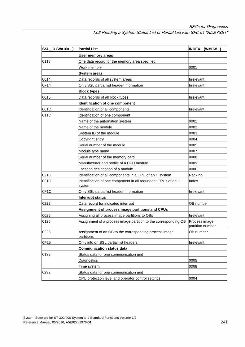
SFCs for Diagnostics 13.3 Reading a System Status List or Partial List with SFC 51 "RDSYSST"
System Software for S7-300/400 System and Standard Functions Volume 1/2 Reference Manual, 05/2010, A5E02789976-01 241
SSL_ID (W#16#...) Partial List INDEX (W#16#...) User memory areas
One data record for the memory area specified 0113 Work memory 0001
System areas 0014 Data records of all system areas Irrelevant 0F14 Only SSL partial list header information Irrelevant
Block types 0015 Data records of all block types Irrelevant Identification of one component 001C Identification of all components Irrelevant
Identification of one component Name of the automation system 0001 Name of the module 0002 System ID of the module 0003 Copyright entry 0004 Serial number of the module 0005 Module type name 0007 Serial number of the memory card 0008 Manufacturer and profile of a CPU module 0009
011C
Location designation of a module 000B 021C Identification of all components in a CPU of an H system Rack no. 031C Identification of one component in all redundant CPUs of an H
system Index
0F1C Only SSL partial list header information Irrelevant Interrupt status 0222 Data record for indicated interrupt OB number Assignment of process image partitions and CPUs 0025 Assigning all process image partitions to OBs Irrelevant 0125 Assignment of a process image partition to the corresponding OB Process image
partition number. 0225 Assignment of an OB to the corresponding process image
partitions OB number.
0F25 Only info on SSL partial list headers Irrelevant Communication status data
Status data for one communication unit Diagnostics 0005
0132
Time system 0008 Status data for one communication unit 0232 CPU protection level and operator control settings 0004
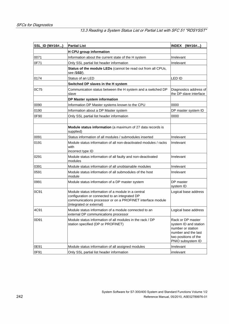
SFCs for Diagnostics 13.3 Reading a System Status List or Partial List with SFC 51 "RDSYSST"
System Software for S7-300/400 System and Standard Functions Volume 1/2 242 Reference Manual, 05/2010, A5E02789976-01
SSL_ID (W#16#...) Partial List INDEX (W#16#...) H CPU group information
0071 Information about the current state of the H system Irrelevant 0F71 Only SSL partial list header information Irrelevant
Status of the module LEDs (cannot be read out from all CPUs, see /102/).
0174 Status of an LED LED ID Switched DP slaves in the H system 0C75 Communication status between the H system and a switched DP
slave Diagnostics address of the DP slave interface
DP Master system information 0090 Information DP Master systems known to the CPU 0000 0190 Information about a DP Master system DP master system ID 0F90 Only SSL partial list header information 0000
Module status information (a maximum of 27 data records is supplied)
0091 Status information of all modules / submodules inserted Irrelevant 0191 Module status information of all non-deactivated modules / racks
with incorrect type ID
Irrelevant
0291 Module status information of all faulty and non-deactivated modules
Irrelevant
0391 Module status information of all unobtainable modules Irrelevant 0591 Module status information of all submodules of the host
module Irrelevant
0991 Module status information of a DP master system DP master system ID
0C91 Module status information of a module in a central configuration or connected to an integrated DP communications processor or on a PROFINET interface module (integrated or external)
Logical base address
4C91 Module status information of a module connected to an external DP communications processor
Logical base address
0D91 Module status information of all modules in the rack / DP station specified (DP or PROFINET)
Rack or DP master system ID and station number or station number and the last two positions of the PNIO subsystem ID
0E91 Module status information of all assigned modules Irrelevant 0F91 Only SSL partial list header information irrelevant

SFCs for Diagnostics 13.3 Reading a System Status List or Partial List with SFC 51 "RDSYSST"
System Software for S7-300/400 System and Standard Functions Volume 1/2 Reference Manual, 05/2010, A5E02789976-01 243
SSL_ID (W#16#...) Partial List INDEX (W#16#...) Rack/station status information
0092 Expected status of the rack in the central configuration / of the stations of a DP master system
0 / DP master system ID
4092 Expected status of the stations of a DP master system connected to an external DP interface
DP master system ID
0192 Activation status of the stations in a DP master system that is connected via an integrated DP interface
DP master system ID
0292 Current status of the rack in the central configuration / of the stations of a DP master system
0 / DP master system ID
4292 Current status of the stations in a DP master system that is connected via an external DP interface module.
DP master system ID
0392 Status of the backup batteries in a rack/module rack of a CPU after at least one battery has failed
0
0492 Status of the overall battery backup status of all racks/module racks of a CPU
0
0592 Status of the 24-V power supply to all racks/module racks of a CPU
0
0692 Diagnostic status of the expansion racks in a central configuration / of the stations of a DP master system connected via an integrated DP interface module
0 / DP master system ID
4692 Diagnostic status of the stations of a DP master system connected via an external DP interface module
DP master system ID
Rack /station status information 0094 Expected status of the rack in the central rack / stations of an IO
controller system 0 / PNIO subsystem ID
0194 Activation status of an IO controller system that is configured and deactivated
PNIO subsystem ID
0294 Actual status of the rack in the central rack / stations of an IO controller system
0 / PNIO subsystem ID
0694 Diagnostic status of the expansion units in the central rack / stations of an IO controller system
0 / PNIO subsystem ID
0794 Maintenance status of the central rack / stations of an IO controller system
0 / PNIO subsystem ID
0F94 Only header information - Extended DP master system / PROFINET IO system information
0195 Extended information about a DP master system DP master system ID 0F95 Only SSL partial list header information 0000
Module status information PROFINET IO and PROFIBUS DP 0696 Module status information of all submodules of a specified module
(only with PROFINET IO on an integrated interface module) Address with I/O ID
0C96 Module status information of a module / a submodule centrally or on an integrated PROFIBUS DP interface module or an a PROFINET interface module (integrated or external)
Start address with I/O ID

SFCs for Diagnostics 13.3 Reading a System Status List or Partial List with SFC 51 "RDSYSST"
System Software for S7-300/400 System and Standard Functions Volume 1/2 244 Reference Manual, 05/2010, A5E02789976-01
SSL_ID (W#16#...) Partial List INDEX (W#16#...)
Tool changer information (PROFINET IO) 009C Information on all tool changers and their tools in a PROFINET IO
system PROFINET IO system ID
019C Information on all tool changers in a PROFINET IO system PROFINET IO system ID
029C Information on one tool changer and its tools Logical address of the tool changer
039C Information on a tool and its IO devices Logical address of one of the IO devices of the tool
0F9C Only SSL partial list header information irrelevant
Diagnostic buffer (a maximum of 21 data records is supplied) 00A0 All entries that can be supplied in the currently active
operating mode Irrelevant
01A0 The most recent entries, the number is specified in the index
Quantity
0FA0 Only SSL partial list header information Irrelevant Diagnostic data on modules
00B1 The first four diagnostic bytes of one module (data record 0) Logical base address 00B2 All diagnostic data of one module (< 220 bytes, data record 1) (no
DP module) Rack, slot
00B3 All diagnostic data of one module (< 220 bytes, data record 1) Logical base address 00B4 Diagnostic data of a DP slave Configured diagnostic
address
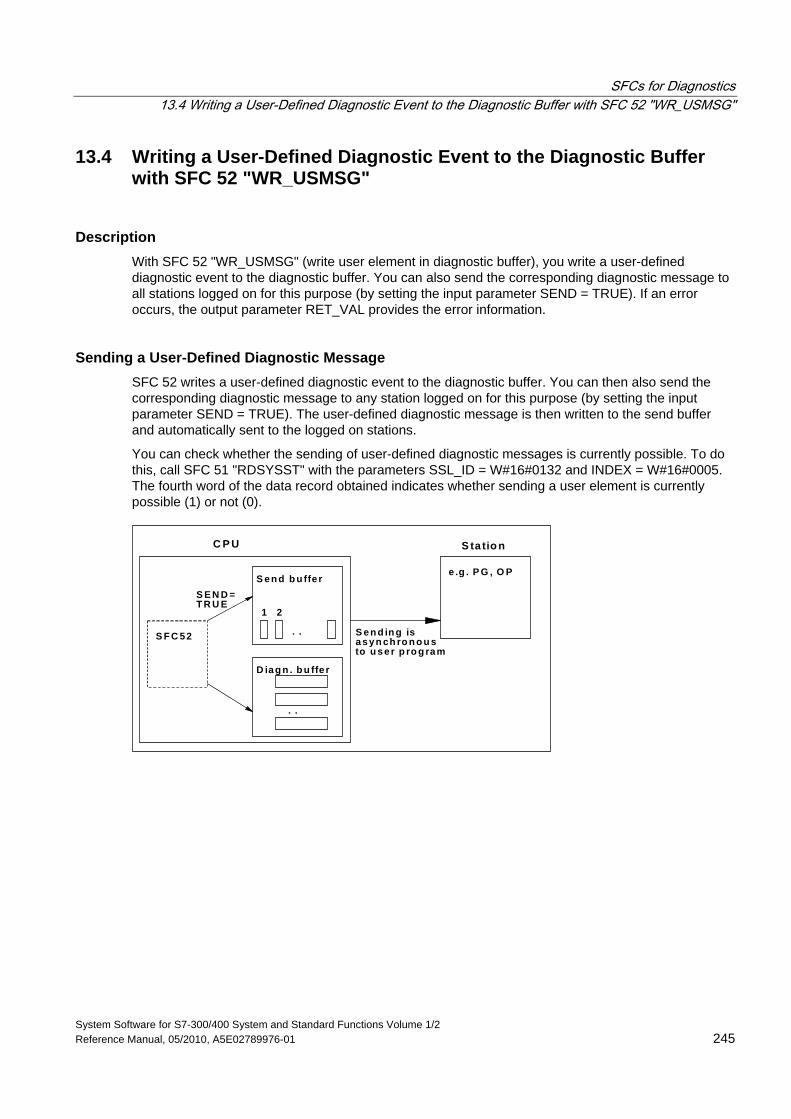
SFCs for Diagnostics 13.4 Writing a User-Defined Diagnostic Event to the Diagnostic Buffer with SFC 52 "WR_USMSG"
System Software for S7-300/400 System and Standard Functions Volume 1/2 Reference Manual, 05/2010, A5E02789976-01 245
13.4 Writing a User-Defined Diagnostic Event to the Diagnostic Buffer with SFC 52 "WR_USMSG"
Description With SFC 52 "WR_USMSG" (write user element in diagnostic buffer), you write a user-defined diagnostic event to the diagnostic buffer. You can also send the corresponding diagnostic message to all stations logged on for this purpose (by setting the input parameter SEND = TRUE). If an error occurs, the output parameter RET_VAL provides the error information.
Sending a User-Defined Diagnostic Message SFC 52 writes a user-defined diagnostic event to the diagnostic buffer. You can then also send the corresponding diagnostic message to any station logged on for this purpose (by setting the input parameter SEND = TRUE). The user-defined diagnostic message is then written to the send buffer and automatically sent to the logged on stations.
You can check whether the sending of user-defined diagnostic messages is currently possible. To do this, call SFC 51 "RDSYSST" with the parameters SSL_ID = W#16#0132 and INDEX = W#16#0005. The fourth word of the data record obtained indicates whether sending a user element is currently possible (1) or not (0).
C P U
S en d b u ffe r
D iag n . b u ffe r
1 2
. .
. .
S F C 52
S E N D =T R U E
S ta tio n
e .g . P G , O P
S en d in g isasyn ch ro n o u sto u ser p ro g ram
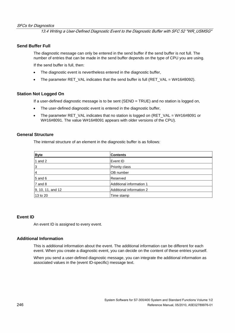
SFCs for Diagnostics 13.4 Writing a User-Defined Diagnostic Event to the Diagnostic Buffer with SFC 52 "WR_USMSG"
System Software for S7-300/400 System and Standard Functions Volume 1/2 246 Reference Manual, 05/2010, A5E02789976-01
Send Buffer Full The diagnostic message can only be entered in the send buffer if the send buffer is not full. The number of entries that can be made in the send buffer depends on the type of CPU you are using.
If the send buffer is full, then:
• The diagnostic event is nevertheless entered in the diagnostic buffer,
• The parameter RET_VAL indicates that the send buffer is full (RET_VAL = W#16#8092).
Station Not Logged On If a user-defined diagnostic message is to be sent (SEND = TRUE) and no station is logged on,
• The user-defined diagnostic event is entered in the diagnostic buffer,
• The parameter RET_VAL indicates that no station is logged on (RET_VAL = W#16#8091 or W#16#8091. The value W#16#8091 appears with older versions of the CPU).
General Structure The internal structure of an element in the diagnostic buffer is as follows:
Byte Contents
1 and 2 Event ID 3 Priority class 4 OB number 5 and 6 Reserved 7 and 8 Additional information 1 9, 10, 11, and 12 Additional information 2 13 to 20 Time stamp
Event ID An event ID is assigned to every event.
Additional Information This is additional information about the event. The additional information can be different for each event. When you create a diagnostic event, you can decide on the content of these entries yourself.
When you send a user-defined diagnostic message, you can integrate the additional information as associated values in the (event ID-specific) message text.
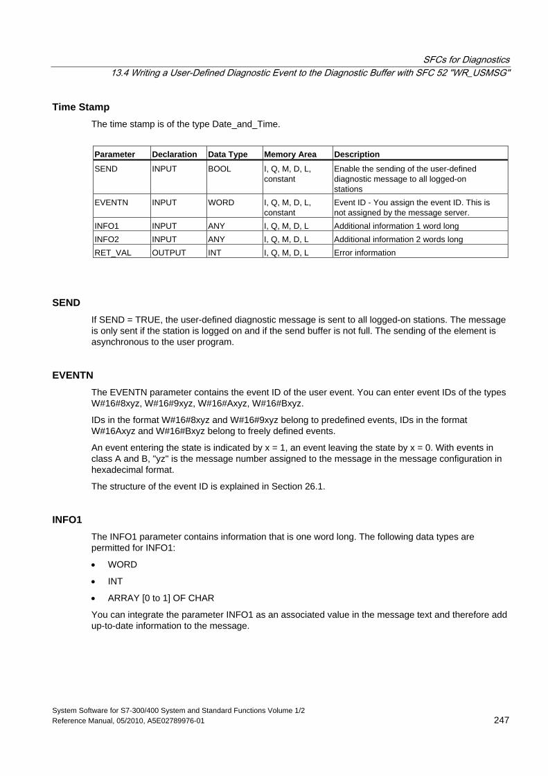
SFCs for Diagnostics 13.4 Writing a User-Defined Diagnostic Event to the Diagnostic Buffer with SFC 52 "WR_USMSG"
System Software for S7-300/400 System and Standard Functions Volume 1/2 Reference Manual, 05/2010, A5E02789976-01 247
Time Stamp The time stamp is of the type Date_and_Time.
Parameter Declaration Data Type Memory Area Description
SEND INPUT BOOL I, Q, M, D, L, constant
Enable the sending of the user-defined diagnostic message to all logged-on stations
EVENTN INPUT WORD I, Q, M, D, L, constant
Event ID - You assign the event ID. This is not assigned by the message server.
INFO1 INPUT ANY I, Q, M, D, L Additional information 1 word long INFO2 INPUT ANY I, Q, M, D, L Additional information 2 words long RET_VAL OUTPUT INT I, Q, M, D, L Error information
SEND If SEND = TRUE, the user-defined diagnostic message is sent to all logged-on stations. The message is only sent if the station is logged on and if the send buffer is not full. The sending of the element is asynchronous to the user program.
EVENTN The EVENTN parameter contains the event ID of the user event. You can enter event IDs of the types W#16#8xyz, W#16#9xyz, W#16#Axyz, W#16#Bxyz.
IDs in the format W#16#8xyz and W#16#9xyz belong to predefined events, IDs in the format W#16Axyz and W#16#Bxyz belong to freely defined events.
An event entering the state is indicated by x = 1, an event leaving the state by x = 0. With events in class A and B, "yz" is the message number assigned to the message in the message configuration in hexadecimal format.
The structure of the event ID is explained in Section 26.1.
INFO1 The INFO1 parameter contains information that is one word long. The following data types are permitted for INFO1:
• WORD
• INT
• ARRAY [0 to 1] OF CHAR
You can integrate the parameter INFO1 as an associated value in the message text and therefore add up-to-date information to the message.
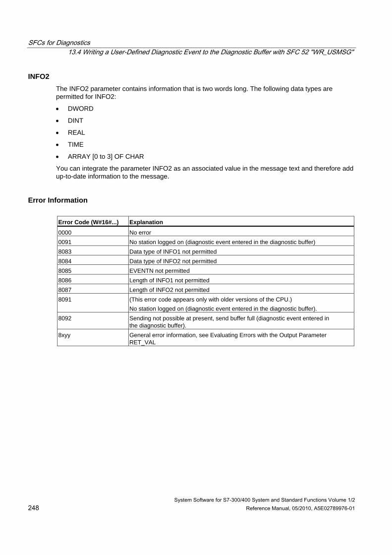
SFCs for Diagnostics 13.4 Writing a User-Defined Diagnostic Event to the Diagnostic Buffer with SFC 52 "WR_USMSG"
System Software for S7-300/400 System and Standard Functions Volume 1/2 248 Reference Manual, 05/2010, A5E02789976-01
INFO2 The INFO2 parameter contains information that is two words long. The following data types are permitted for INFO2:
• DWORD
• DINT
• REAL
• TIME
• ARRAY [0 to 3] OF CHAR
You can integrate the parameter INFO2 as an associated value in the message text and therefore add up-to-date information to the message.
Error Information Error Code (W#16#...) Explanation
0000 No error 0091 No station logged on (diagnostic event entered in the diagnostic buffer) 8083 Data type of INFO1 not permitted 8084 Data type of INFO2 not permitted 8085 EVENTN not permitted 8086 Length of INFO1 not permitted 8087 Length of INFO2 not permitted 8091 (This error code appears only with older versions of the CPU.)
No station logged on (diagnostic event entered in the diagnostic buffer). 8092 Sending not possible at present, send buffer full (diagnostic event entered in
the diagnostic buffer). 8xyy General error information, see Evaluating Errors with the Output Parameter
RET_VAL
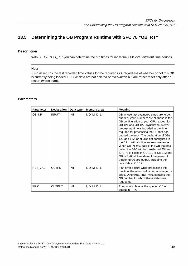
SFCs for Diagnostics 13.5 Determining the OB Program Runtime with SFC 78 "OB_RT"
System Software for S7-300/400 System and Standard Functions Volume 1/2 Reference Manual, 05/2010, A5E02789976-01 249
13.5 Determining the OB Program Runtime with SFC 78 "OB_RT"
Description With SFC 78 ”OB_RT” you can determine the run times for individual OBs over different time periods.
Note
SFC 78 returns the last recorded time values for the required OB, regardless of whether or not this OB is currently being loaded. SFC 78 data are not deleted or overwritten but are rather reset only after a restart (warm start).
Parameters Parameter Declaration Data type Memory area Meaning
OB_NR INPUT INT I, Q, M, D, L OB whose last evaluated times are to be queried. Valid numbers are all those in the OB configuration of your CPU, except for OB 121 and OB 122. Synchronous error processing time is included in the time required for processing the OB that has caused the error. The declaration of OBs 121 and 122, or of OBs not configured in the CPU, will result in an error message. When OB_NR=0, data of the OB that has called the SFC will be transferred. When SFC 78 is called in OB 121 or OB 122 and OB_NR=0, all time data of the interrupt triggering OB are output, including the time data in OB 12x.
RET_VAL OUTPUT INT I, Q, M, D, L If an error occurs while processing this function, the return value contains an error code. Otherwise, RET_VAL contains the OB number for which these data were requested.
PRIO OUTPUT INT I, Q, M, D, L The priority class of the queried OB is output in PRIO
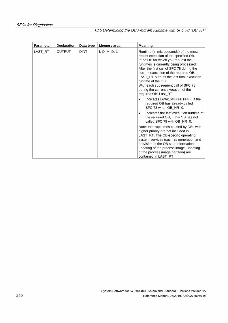
SFCs for Diagnostics 13.5 Determining the OB Program Runtime with SFC 78 "OB_RT"
System Software for S7-300/400 System and Standard Functions Volume 1/2 250 Reference Manual, 05/2010, A5E02789976-01
Parameter Declaration Data type Memory area Meaning
LAST_RT OUTPUT DINT I, Q, M, D, L Runtime (in microseconds) of the most recent execution of the specified OB. If the OB for which you request the runtimes is currently being processed: After the first call of SFC 78 during the current execution of the required OB, LAST_RT outputs the last total execution runtime of the OB. With each subsequent call of SFC 78 during the current execution of the required OB, Last_RT • Indicates DW#16#FFFF FFFF, if the
required OB has already called SFC 78 when OB_NR=0.
• Indicates the last execution runtime of the required OB, if this OB has not called SFC 78 with OB_NR=0.
Note: Interrupt times caused by OBs with higher priority are not included in LAST_RT. The OB-specific operating system services (such as generation and provision of the OB start information, updating of the process image, updating of the process image partition) are contained in LAST_RT
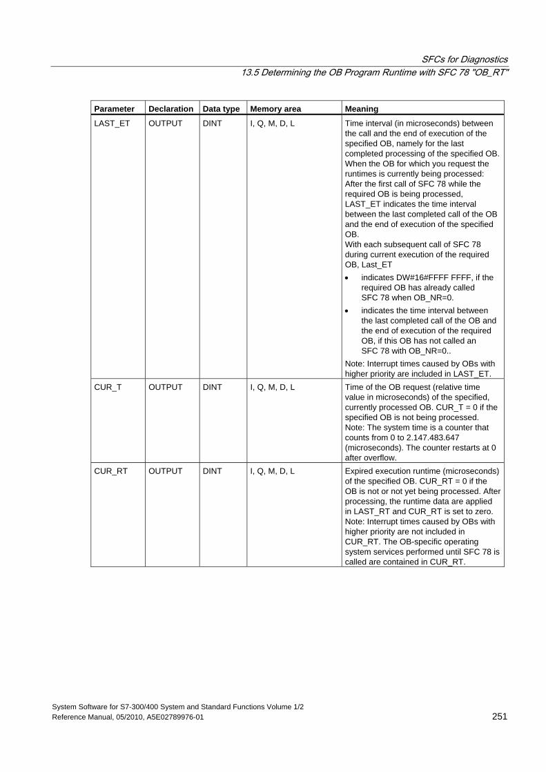
SFCs for Diagnostics 13.5 Determining the OB Program Runtime with SFC 78 "OB_RT"
System Software for S7-300/400 System and Standard Functions Volume 1/2 Reference Manual, 05/2010, A5E02789976-01 251
Parameter Declaration Data type Memory area Meaning
LAST_ET OUTPUT DINT I, Q, M, D, L Time interval (in microseconds) between the call and the end of execution of the specified OB, namely for the last completed processing of the specified OB.When the OB for which you request the runtimes is currently being processed: After the first call of SFC 78 while the required OB is being processed, LAST_ET indicates the time interval between the last completed call of the OB and the end of execution of the specified OB. With each subsequent call of SFC 78 during current execution of the required OB, Last_ET • indicates DW#16#FFFF FFFF, if the
required OB has already called SFC 78 when OB_NR=0.
• indicates the time interval between the last completed call of the OB and the end of execution of the required OB, if this OB has not called an SFC 78 with OB_NR=0..
Note: Interrupt times caused by OBs with higher priority are included in LAST_ET.
CUR_T OUTPUT DINT I, Q, M, D, L Time of the OB request (relative time value in microseconds) of the specified, currently processed OB. CUR_T = 0 if the specified OB is not being processed. Note: The system time is a counter that counts from 0 to 2.147.483.647 (microseconds). The counter restarts at 0 after overflow.
CUR_RT OUTPUT DINT I, Q, M, D, L Expired execution runtime (microseconds) of the specified OB. CUR_RT = 0 if the OB is not or not yet being processed. After processing, the runtime data are applied in LAST_RT and CUR_RT is set to zero. Note: Interrupt times caused by OBs with higher priority are not included in CUR_RT. The OB-specific operating system services performed until SFC 78 is called are contained in CUR_RT.
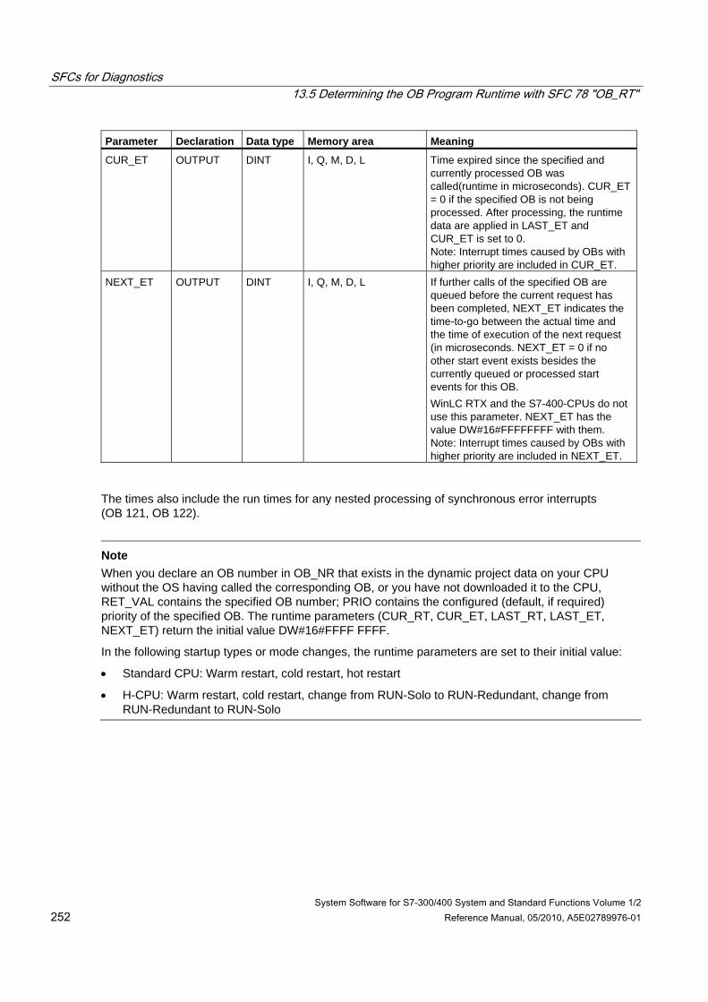
SFCs for Diagnostics 13.5 Determining the OB Program Runtime with SFC 78 "OB_RT"
System Software for S7-300/400 System and Standard Functions Volume 1/2 252 Reference Manual, 05/2010, A5E02789976-01
Parameter Declaration Data type Memory area Meaning
CUR_ET OUTPUT DINT I, Q, M, D, L Time expired since the specified and currently processed OB was called(runtime in microseconds). CUR_ET = 0 if the specified OB is not being processed. After processing, the runtime data are applied in LAST_ET and CUR_ET is set to 0. Note: Interrupt times caused by OBs with higher priority are included in CUR_ET.
NEXT_ET OUTPUT DINT I, Q, M, D, L If further calls of the specified OB are queued before the current request has been completed, NEXT_ET indicates the time-to-go between the actual time and the time of execution of the next request (in microseconds. NEXT_ET = 0 if no other start event exists besides the currently queued or processed start events for this OB. WinLC RTX and the S7-400-CPUs do not use this parameter. NEXT_ET has the value DW#16#FFFFFFFF with them. Note: Interrupt times caused by OBs with higher priority are included in NEXT_ET.
The times also include the run times for any nested processing of synchronous error interrupts (OB 121, OB 122).
Note
When you declare an OB number in OB_NR that exists in the dynamic project data on your CPU without the OS having called the corresponding OB, or you have not downloaded it to the CPU, RET_VAL contains the specified OB number; PRIO contains the configured (default, if required) priority of the specified OB. The runtime parameters (CUR_RT, CUR_ET, LAST_RT, LAST_ET, NEXT_ET) return the initial value DW#16#FFFF FFFF.
In the following startup types or mode changes, the runtime parameters are set to their initial value:
• Standard CPU: Warm restart, cold restart, hot restart
• H-CPU: Warm restart, cold restart, change from RUN-Solo to RUN-Redundant, change from RUN-Redundant to RUN-Solo
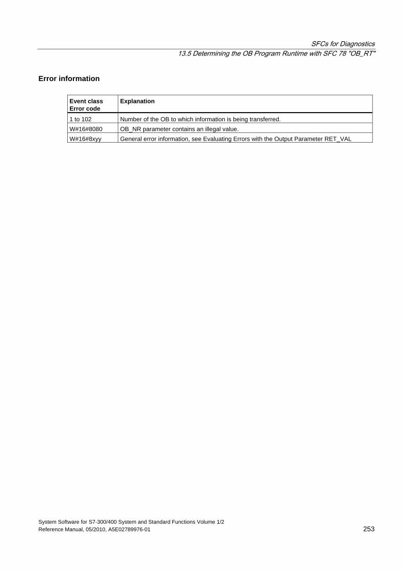
SFCs for Diagnostics 13.5 Determining the OB Program Runtime with SFC 78 "OB_RT"
System Software for S7-300/400 System and Standard Functions Volume 1/2 Reference Manual, 05/2010, A5E02789976-01 253
Error information Event class Error code
Explanation
1 to 102 Number of the OB to which information is being transferred. W#16#8080 OB_NR parameter contains an illegal value. W#16#8xyy General error information, see Evaluating Errors with the Output Parameter RET_VAL
SFCs for Diagnostics 13.6 Diagnosis of the Current Connection Status with SFC 87 "C_DIAG"
System Software for S7-300/400 System and Standard Functions Volume 1/2 254 Reference Manual, 05/2010, A5E02789976-01
13.6 Diagnosis of the Current Connection Status with SFC 87 "C_DIAG"
Description You can use SFC 87 "C_DIAG" to determine the current status of all S7 connections and of all fault-tolerant S7 connections (or their partial connection).
Suitable evaluation of these connection data lets you recognize failures of S7 connections as well as of current S7 connections and report these, should the occasion arise, to an operating and visualization system. Monitored connections can be a connection between automation systems as well as the connection of an automation system to an operating and visualization system.
Note
A change in the operating state of the CPU: RUN -> STOP ->RUN, does not affect the state of the configured connections. Exception: When an H station changes from the Redundant system state to the Stop system state, the partial connections of all fault-tolerant connections to the standby CPU will be disconnected. After a power failure, on the other hand, all configured connections will be reestablished and this changes the connection status. The first time SFC 87 is called during or after startup, the connection information will differ, depending on whether the last operating mode of the CPU was STOP or POWER OFF.
Operating Mode The SFC 87 "C_DIAG" is an asynchronous SFC operation, that is to say, processing can be extended over multiple SFC calls.
You start the job by calling the SFC 87 with REQ=1.
If it was possible to execute the job immediately, the SFC returns the value 0 in the output parameter BUSY. If BUSY is 1 the job is still active.
When Do You Call the SFC 87? To recognize the failure of S7 connections and current S7 connections, call the SFC87 in a cyclic interrupt OB that is started, for example, every 10 seconds by the operating system.
Since the status of a connection normally does not change, it is appropriate to copy the connection data to the user program with these cyclic calls only if they have changed since their last call (call with MODE=B#16#02, see below).
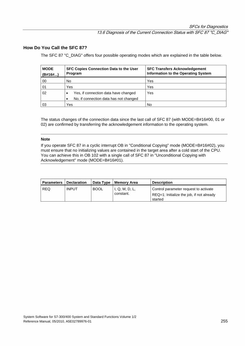
SFCs for Diagnostics 13.6 Diagnosis of the Current Connection Status with SFC 87 "C_DIAG"
System Software for S7-300/400 System and Standard Functions Volume 1/2 Reference Manual, 05/2010, A5E02789976-01 255
How Do You Call the SFC 87? The SFC 87 "C_DIAG" offers four possible operating modes which are explained in the table below.
MODE (B#16#...)
SFC Copies Connection Data to the User Program
SFC Transfers Acknowledgement Information to the Operating System
00 No Yes 01 Yes Yes 02 • Yes, if connection data have changed
• No, if connection data has not changed Yes
03 Yes No
The status changes of the connection data since the last call of SFC 87 (with MODE=B#16#00, 01 or 02) are confirmed by transferring the acknowledgement information to the operating system.
Note
If you operate SFC 87 in a cyclic interrupt OB in "Conditional Copying" mode (MODE=B#16#02), you must ensure that no initializing values are contained in the target area after a cold start of the CPU. You can achieve this in OB 102 with a single call of SFC 87 in "Unconditional Copying with Acknowledgement" mode (MODE=B#16#01).
Parameters Declaration Data Type Memory Area Description
REQ INPUT BOOL I, Q, M, D, L, constant.
Control parameter request to activate REQ=1: Initialize the job, if not already started
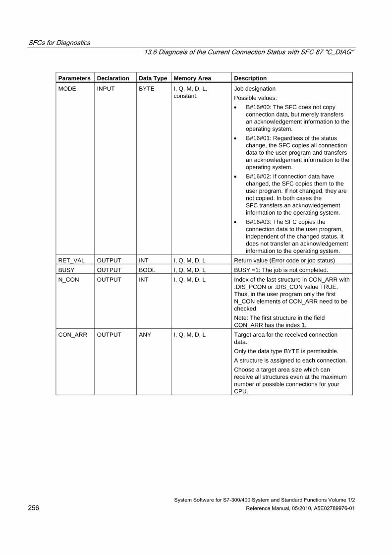
SFCs for Diagnostics 13.6 Diagnosis of the Current Connection Status with SFC 87 "C_DIAG"
System Software for S7-300/400 System and Standard Functions Volume 1/2 256 Reference Manual, 05/2010, A5E02789976-01
Parameters Declaration Data Type Memory Area Description
MODE INPUT BYTE I, Q, M, D, L, constant.
Job designation Possible values: • B#16#00: The SFC does not copy
connection data, but merely transfers an acknowledgement information to the operating system.
• B#16#01: Regardless of the status change, the SFC copies all connection data to the user program and transfers an acknowledgement information to the operating system.
• B#16#02: If connection data have changed, the SFC copies them to the user program. If not changed, they are not copied. In both cases the SFC transfers an acknowledgement information to the operating system.
• B#16#03: The SFC copies the connection data to the user program, independent of the changed status. It does not transfer an acknowledgement information to the operating system.
RET_VAL OUTPUT INT I, Q, M, D, L Return value (Error code or job status) BUSY OUTPUT BOOL I, Q, M, D, L BUSY =1: The job is not completed. N_CON OUTPUT INT I, Q, M, D, L Index of the last structure in CON_ARR with
.DIS_PCON or .DIS_CON value TRUE. Thus, in the user program only the first N_CON elements of CON_ARR need to be checked. Note: The first structure in the field CON_ARR has the index 1.
CON_ARR OUTPUT ANY I, Q, M, D, L Target area for the received connection data. Only the data type BYTE is permissible. A structure is assigned to each connection. Choose a target area size which can receive all structures even at the maximum number of possible connections for your CPU.
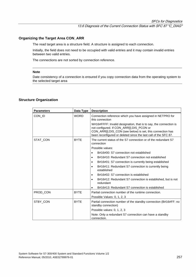
SFCs for Diagnostics 13.6 Diagnosis of the Current Connection Status with SFC 87 "C_DIAG"
System Software for S7-300/400 System and Standard Functions Volume 1/2 Reference Manual, 05/2010, A5E02789976-01 257
Organizing the Target Area CON_ARR The read target area is a structure field. A structure is assigned to each connection.
Initially, the field does not need to be occupied with valid entries and it may contain invalid entries between two valid entries.
The connections are not sorted by connection reference.
Note
Date consistency of a connection is ensured if you copy connection data from the operating system to the selected target area
Structure Organization Parameters Data Type Description
CON_ID WORD Connection reference which you have assigned in NETPRO for this connection W#16#FFFF: Invalid designation, that is to say, the connection is not configured. If CON_ARR[i].DIS_PCON or CON_ARR[i].DIS_CON (see below) is set, this connection has been reconfigured or deleted since the last call of the SFC 87.
STAT_CON BYTE The current status of the S7 connection or of the redundant S7 connection Possible values: • B#16#00: S7 connection not established • B#16#10: Redundant S7 connection not established • B#16#01: S7 connection is currently being established • B#16#11: Redundant S7 connection is currently being
established • B#16#02: S7 connection is established • B#16#12: Redundant S7 connection is established, but is not
redundant • B#16#13: Redundant S7 connection is established
PROD_CON BYTE Partial connection number of the runtime connection. Possible Values: 0, 1, 2, 3
STBY_CON BYTE Partial connection number of the standby connection (B#16#FF: no standby connection) Possible values: 0, 1, 2, 3 Note: Only a redundant S7 connection can have a standby connection.
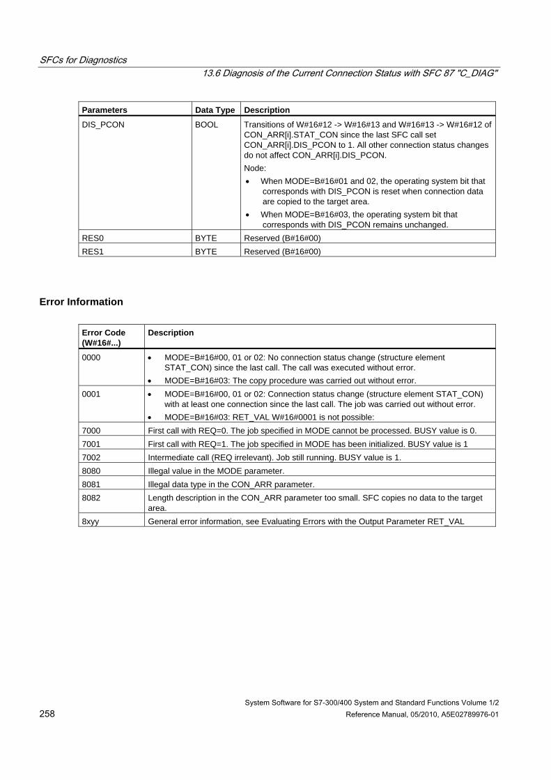
SFCs for Diagnostics 13.6 Diagnosis of the Current Connection Status with SFC 87 "C_DIAG"
System Software for S7-300/400 System and Standard Functions Volume 1/2 258 Reference Manual, 05/2010, A5E02789976-01
Parameters Data Type Description
DIS_PCON BOOL Transitions of W#16#12 -> W#16#13 and W#16#13 -> W#16#12 of CON_ARR[i].STAT_CON since the last SFC call set CON_ARR[i].DIS_PCON to 1. All other connection status changes do not affect CON_ARR[i].DIS_PCON. Node: • When MODE=B#16#01 and 02, the operating system bit that
corresponds with DIS_PCON is reset when connection data are copied to the target area.
• When MODE=B#16#03, the operating system bit that corresponds with DIS_PCON remains unchanged.
RES0 BYTE Reserved (B#16#00) RES1 BYTE Reserved (B#16#00)
Error Information Error Code (W#16#...)
Description
0000 • MODE=B#16#00, 01 or 02: No connection status change (structure element STAT_CON) since the last call. The call was executed without error.
• MODE=B#16#03: The copy procedure was carried out without error. 0001 • MODE=B#16#00, 01 or 02: Connection status change (structure element STAT_CON)
with at least one connection since the last call. The job was carried out without error. • MODE=B#16#03: RET_VAL W#16#0001 is not possible:
7000 First call with REQ=0. The job specified in MODE cannot be processed. BUSY value is 0. 7001 First call with REQ=1. The job specified in MODE has been initialized. BUSY value is 1 7002 Intermediate call (REQ irrelevant). Job still running. BUSY value is 1. 8080 Illegal value in the MODE parameter. 8081 Illegal data type in the CON_ARR parameter. 8082 Length description in the CON_ARR parameter too small. SFC copies no data to the target
area. 8xyy General error information, see Evaluating Errors with the Output Parameter RET_VAL
SFCs for Diagnostics 13.7 Identifying the Bus Topology of a DP Master System with SFC 103 "DP_TOPOL"
System Software for S7-300/400 System and Standard Functions Volume 1/2 Reference Manual, 05/2010, A5E02789976-01 259
13.7 Identifying the Bus Topology of a DP Master System with SFC 103 "DP_TOPOL"
Description Call SFC 103 "DP_TOPOL" with its diagnostics repeaters to initiate the identification of the bus topology of a selected a DP master system. All diagnostics repeaters connected to a DP master system are addressed when SFC 103 is called.
Note The topology of only one DP master system can be identified at a given time.
The identification of the topology is a prerequisite for a detailed display of the error location in the event of a line error. After the installation or any changes to the physical structure of a DP master system, once again identify the topology with SFC 103.
Changes to the physical structure includes:
• Change in cable lengths
• Addition or removal of nodes or of components with repeater function
• Change in node addresses
Each diagnostic repeater enters the result (PROFIBUS address of all nodes and their absolute distance to the diagnostic repeater) in a topology table. You can read these values under STEP 7.
We recommend to call SFC 103 in OB1 or in a watchdog interrupt OB. An S7-300 does not allow this call in one of the startup OBs.
The SFC writes error messages returned by the diagnostic repeater to the outputs DPR and DPRI for as long as the SFC is being executed. If more than one diagnostic repeater in the selected DP master system reports an error, the SFC enters in DPR and DPRI only information relevant to the diagnostic repeater that has first generated an error message. Call SFC 13 "DPNRM_DG" or STEP 7 to read the complete diagnostic information. The value of outputs DPR and DPRI is NULL if no error is reported by a diagnostic repeater.
If you want to trigger another topology determination after an error has occurred, you must first reset SFC103. To do this, call the SFC with REQ=0 and R=1.
Operating method SFC 103 "DP_TOPOL" operates asynchronously, that is, its execution requires several SFC calls. Call SFC 103 with REQ = 1 to initiate identification of the DP bus topology and call SFC 103 with R=1 to abort the process.
The job status is indicated at the output parameters RET_VAL and BUSY, see also Meaning of REQ, RET_VAL and BUSY with asynchronously operating SFCs.
Note It may take several minutes to identify the topology.
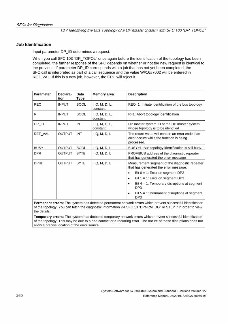
SFCs for Diagnostics 13.7 Identifying the Bus Topology of a DP Master System with SFC 103 "DP_TOPOL"
System Software for S7-300/400 System and Standard Functions Volume 1/2 260 Reference Manual, 05/2010, A5E02789976-01
Job Identification Input parameter DP_ID determines a request.
When you call SFC 103 "DP_TOPOL" once again before the identification of the topology has been completed, the further response of the SFC depends on whether or not the new request is identical to the previous: If parameter DP_ID corresponds with a job that has not yet been completed, the SFC call is interpreted as part of a call sequence and the value W#16#7002 will be entered in RET_VAL. If this is a new job, however, the CPU will reject it.
Parameter Declara-
tion Data Type
Memory area Description
REQ INPUT BOOL I, Q, M, D, L, constant
REQ=1: Initiate identification of the bus topology
R INPUT BOOL I, Q, M, D, L, constant
R=1: Abort topology identification
DP_ID INPUT INT I, Q, M, D, L, constant
DP master system ID of the DP master system whose topology is to be identified
RET_VAL OUTPUT INT I, Q, M, D, L The return value will contain an error code if an error occurs while the function is being processed.
BUSY OUTPUT BOOL I, Q, M, D, L BUSY=1: Bus topology identification is still busy. DPR OUTPUT BYTE I, Q, M, D, L PROFIBUS address of the diagnostic repeater
that has generated the error message DPRI OUTPUT BYTE I, Q, M, D, L Measurement segment of the diagnostic repeater
that has generated the error message: • Bit 0 = 1: Error on segment DP2 • Bit 1 = 1: Error on segment DP3 • Bit 4 = 1: Temporary disruptions at segment
DP3 • Bit 5 = 1: Permanent disruptions at segment
DP3 Permanent errors: The system has detected permanent network errors which prevent successful identification of the topology. You can fetch the diagnostic information via SFC 13 "DPNRM_DG" or STEP 7 in order to view the details. Temporary errors: The system has detected temporary network errors which prevent successful identification of the topology. This may be due to a bad contact or a recurring error. The nature of these disruptions does not allow a precise location of the error source.
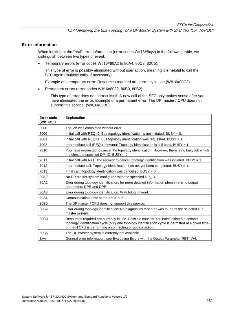
SFCs for Diagnostics 13.7 Identifying the Bus Topology of a DP Master System with SFC 103 "DP_TOPOL"
System Software for S7-300/400 System and Standard Functions Volume 1/2 Reference Manual, 05/2010, A5E02789976-01 261
Error information When looking at the "real" error information (error codes W#16#8xyz) in the following table, we distinguish between two types of event:
• Temporary errors (error codes W#16#80A2 to 80A4, 80C3, 80C5):
This type of error is possibly eliminated without user action, meaning it is helpful to call the SFC again (multiple calls, if necessary).
Example of a temporary error: Resources required are currently in use (W#16#80C3).
• Permanent errors (error codes W#16#8082, 80B0, 80B2):
This type of error does not correct itself. A new call of the SFC only makes sense after you have eliminated the error. Example of a permanent error: The DP master / CPU does not support this service. (W#16#80B0).
Error code (W#16#...)
Explanation
0000 The job was completed without error. 7000 Initial call with REQ=0. Bus topology identification is not initiated. BUSY = 0. 7001 Initial call with REQ=1. Bus topology identification was requested. BUSY = 1. 7002 Intermediate call (REQ irrelevant): Topology identification is still busy. BUSY = 1. 7010 You have requested to cancel the topology identification. However, there is no busy job which
matches the specified DP_ID. BUSY = 0. 7011 Initial call with R=1. The request to cancel topology identification was initiated. BUSY = 1. 7012 Intermediate call: Topology identification has not yet been completed. BUSY = 1. 7013 Final call: Topology identification was cancelled. BUSY = 0. 8082 No DP master system configured with the specified DP_ID. 80A2 Error during topology identification; for more detailed information please refer to output
parameters DPR and DPRI. 80A3 Error during topology identification: Watchdog timeout. 80A4 Communication error at the am K bus 80B0 The DP master / CPU does not support this service. 80B2 Error during topology identification: No diagnostics repeater was found at the selected DP
master system. 80C3 Resources required are currently in use. Possible causes: You have initiated a second
topology identification cycle (only one topology identification cycle is permitted at a given time) or the H CPU is performing a connecting or update action.
80C5 The DP master system is currently not available. 8xyy General error information, see Evaluating Errors with the Output Parameter RET_VAL
SFCs for Diagnostics 13.7 Identifying the Bus Topology of a DP Master System with SFC 103 "DP_TOPOL"
System Software for S7-300/400 System and Standard Functions Volume 1/2 262 Reference Manual, 05/2010, A5E02789976-01
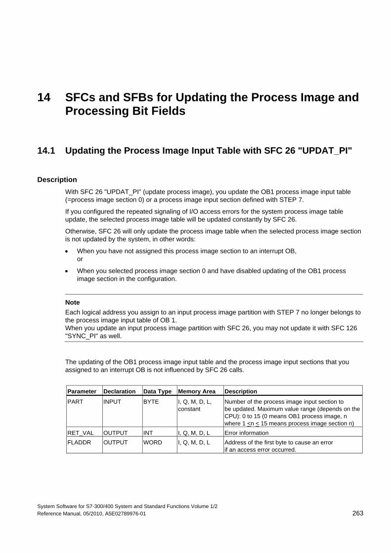
System Software for S7-300/400 System and Standard Functions Volume 1/2 Reference Manual, 05/2010, A5E02789976-01 263
14 SFCs and SFBs for Updating the Process Image and Processing Bit Fields
14.1 Updating the Process Image Input Table with SFC 26 "UPDAT_PI"
Description With SFC 26 "UPDAT_PI" (update process image), you update the OB1 process image input table (=process image section 0) or a process image input section defined with STEP 7.
If you configured the repeated signaling of I/O access errors for the system process image table update, the selected process image table will be updated constantly by SFC 26.
Otherwise, SFC 26 will only update the process image table when the selected process image section is not updated by the system, in other words:
• When you have not assigned this process image section to an interrupt OB, or
• When you selected process image section 0 and have disabled updating of the OB1 process image section in the configuration.
Note
Each logical address you assign to an input process image partition with STEP 7 no longer belongs to the process image input table of OB 1. When you update an input process image partition with SFC 26, you may not update it with SFC 126 "SYNC_PI" as well.
The updating of the OB1 process image input table and the process image input sections that you assigned to an interrupt OB is not influenced by SFC 26 calls.
Parameter Declaration Data Type Memory Area Description
PART INPUT BYTE I, Q, M, D, L, constant
Number of the process image input section to be updated. Maximum value range (depends on the CPU): 0 to 15 (0 means OB1 process image, n where 1 <n < 15 means process image section n)
RET_VAL OUTPUT INT I, Q, M, D, L Error information FLADDR OUTPUT WORD I, Q, M, D, L Address of the first byte to cause an error
if an access error occurred.
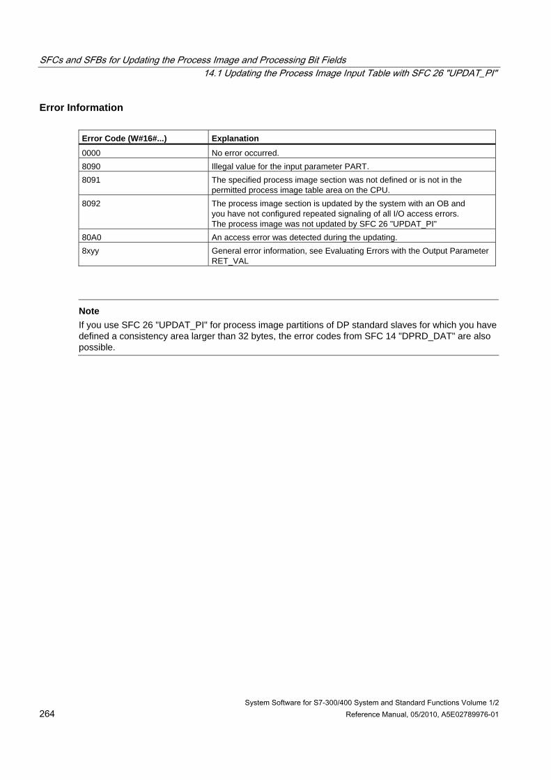
SFCs and SFBs for Updating the Process Image and Processing Bit Fields 14.1 Updating the Process Image Input Table with SFC 26 "UPDAT_PI"
System Software for S7-300/400 System and Standard Functions Volume 1/2 264 Reference Manual, 05/2010, A5E02789976-01
Error Information Error Code (W#16#...) Explanation
0000 No error occurred. 8090 Illegal value for the input parameter PART. 8091 The specified process image section was not defined or is not in the
permitted process image table area on the CPU. 8092 The process image section is updated by the system with an OB and
you have not configured repeated signaling of all I/O access errors. The process image was not updated by SFC 26 "UPDAT_PI"
80A0 An access error was detected during the updating. 8xyy General error information, see Evaluating Errors with the Output Parameter
RET_VAL
Note
If you use SFC 26 "UPDAT_PI" for process image partitions of DP standard slaves for which you have defined a consistency area larger than 32 bytes, the error codes from SFC 14 "DPRD_DAT" are also possible.
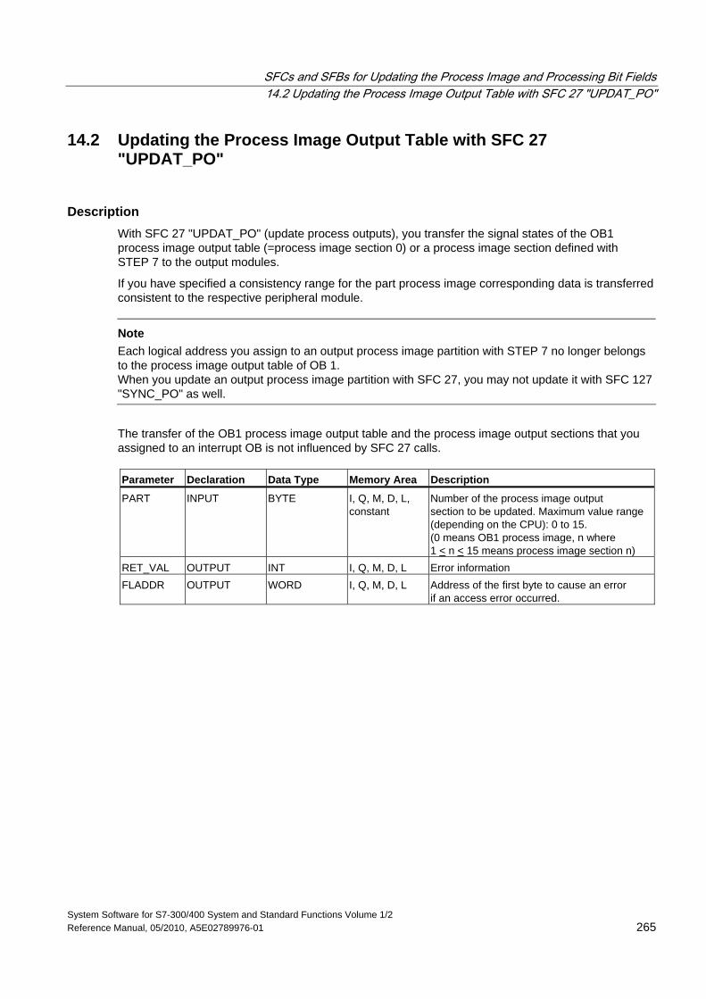
SFCs and SFBs for Updating the Process Image and Processing Bit Fields 14.2 Updating the Process Image Output Table with SFC 27 "UPDAT_PO"
System Software for S7-300/400 System and Standard Functions Volume 1/2 Reference Manual, 05/2010, A5E02789976-01 265
14.2 Updating the Process Image Output Table with SFC 27 "UPDAT_PO"
Description With SFC 27 "UPDAT_PO" (update process outputs), you transfer the signal states of the OB1 process image output table (=process image section 0) or a process image section defined with STEP 7 to the output modules.
If you have specified a consistency range for the part process image corresponding data is transferred consistent to the respective peripheral module.
Note Each logical address you assign to an output process image partition with STEP 7 no longer belongs to the process image output table of OB 1. When you update an output process image partition with SFC 27, you may not update it with SFC 127 "SYNC_PO" as well.
The transfer of the OB1 process image output table and the process image output sections that you assigned to an interrupt OB is not influenced by SFC 27 calls. Parameter Declaration Data Type Memory Area Description
PART INPUT BYTE I, Q, M, D, L, constant
Number of the process image output section to be updated. Maximum value range (depending on the CPU): 0 to 15. (0 means OB1 process image, n where 1 < n < 15 means process image section n)
RET_VAL OUTPUT INT I, Q, M, D, L Error information FLADDR OUTPUT WORD I, Q, M, D, L Address of the first byte to cause an error
if an access error occurred.
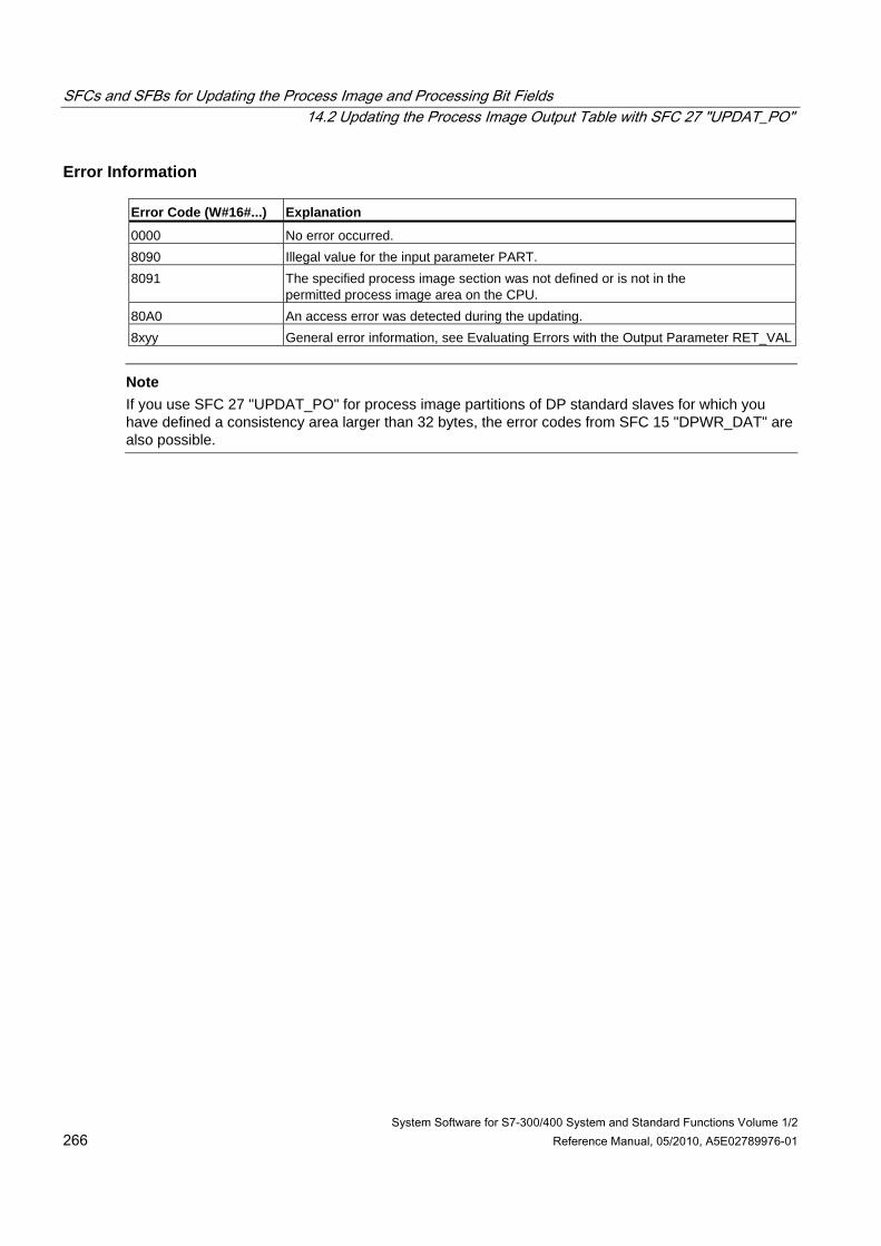
SFCs and SFBs for Updating the Process Image and Processing Bit Fields 14.2 Updating the Process Image Output Table with SFC 27 "UPDAT_PO"
System Software for S7-300/400 System and Standard Functions Volume 1/2 266 Reference Manual, 05/2010, A5E02789976-01
Error Information Error Code (W#16#...) Explanation
0000 No error occurred. 8090 Illegal value for the input parameter PART. 8091 The specified process image section was not defined or is not in the
permitted process image area on the CPU. 80A0 An access error was detected during the updating. 8xyy General error information, see Evaluating Errors with the Output Parameter RET_VAL
Note
If you use SFC 27 "UPDAT_PO" for process image partitions of DP standard slaves for which you have defined a consistency area larger than 32 bytes, the error codes from SFC 15 "DPWR_DAT" are also possible.
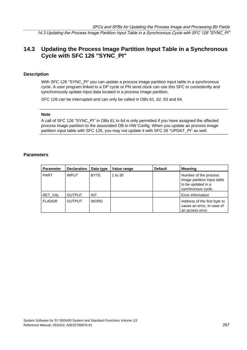
SFCs and SFBs for Updating the Process Image and Processing Bit Fields 14.3 Updating the Process Image Partition Input Table in a Synchronous Cycle with SFC 126 "SYNC_PI"
System Software for S7-300/400 System and Standard Functions Volume 1/2 Reference Manual, 05/2010, A5E02789976-01 267
14.3 Updating the Process Image Partition Input Table in a Synchronous Cycle with SFC 126 "SYNC_PI"
Description With SFC 126 "SYNC_PI” you can update a process image partition input table in a synchronous cycle. A user program linked to a DP cycle or PN send clock can use this SFC to consistently and synchronously update input data located in a process image partition.
SFC 126 can be interrupted and can only be called in OBs 61, 62, 63 and 64.
Note
A call of SFC 126 "SYNC_PI" in OBs 61 to 64 is only permitted if you have assigned the affected process image partition to the associated OB in HW Config. When you update an process image partition input table with SFC 126, you may not update it with SFC 26 "UPDAT_PI" as well.
Parameters Parameter Declaration Data type Value range Default Meaning
PART INPUT BYTE 1 to 30 Number of the process image partition input table to be updated in a synchronous cycle.
RET_VAL OUTPUT INT Error information FLADDR OUTPUT WORD Address of the first byte to
cause an error, in case of an access error.
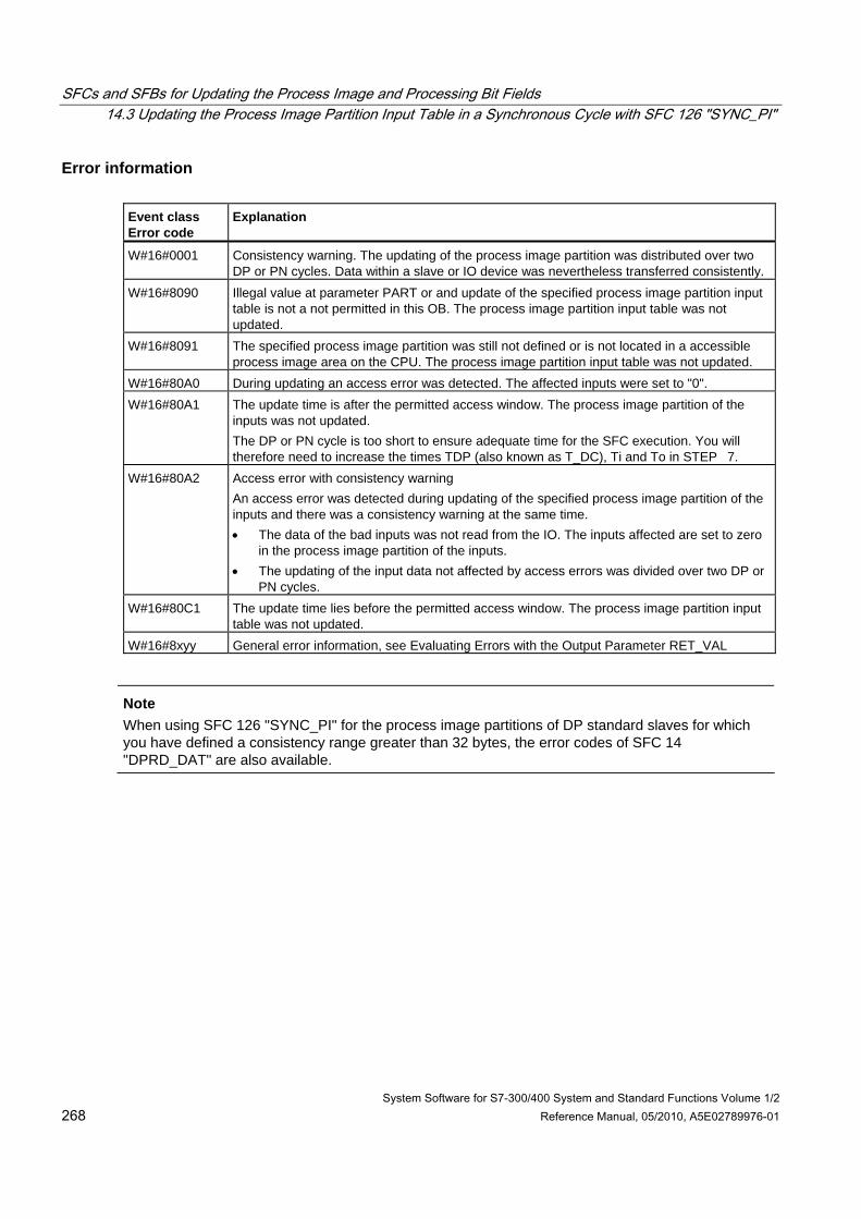
SFCs and SFBs for Updating the Process Image and Processing Bit Fields 14.3 Updating the Process Image Partition Input Table in a Synchronous Cycle with SFC 126 "SYNC_PI"
System Software for S7-300/400 System and Standard Functions Volume 1/2 268 Reference Manual, 05/2010, A5E02789976-01
Error information Event class Error code
Explanation
W#16#0001 Consistency warning. The updating of the process image partition was distributed over two DP or PN cycles. Data within a slave or IO device was nevertheless transferred consistently.
W#16#8090 Illegal value at parameter PART or and update of the specified process image partition input table is not a not permitted in this OB. The process image partition input table was not updated.
W#16#8091 The specified process image partition was still not defined or is not located in a accessible process image area on the CPU. The process image partition input table was not updated.
W#16#80A0 During updating an access error was detected. The affected inputs were set to "0". W#16#80A1 The update time is after the permitted access window. The process image partition of the
inputs was not updated. The DP or PN cycle is too short to ensure adequate time for the SFC execution. You will therefore need to increase the times TDP (also known as T_DC), Ti and To in STEP 7.
W#16#80A2 Access error with consistency warning An access error was detected during updating of the specified process image partition of the inputs and there was a consistency warning at the same time. • The data of the bad inputs was not read from the IO. The inputs affected are set to zero
in the process image partition of the inputs. • The updating of the input data not affected by access errors was divided over two DP or
PN cycles. W#16#80C1 The update time lies before the permitted access window. The process image partition input
table was not updated. W#16#8xyy General error information, see Evaluating Errors with the Output Parameter RET_VAL
Note When using SFC 126 "SYNC_PI" for the process image partitions of DP standard slaves for which you have defined a consistency range greater than 32 bytes, the error codes of SFC 14 "DPRD_DAT" are also available.
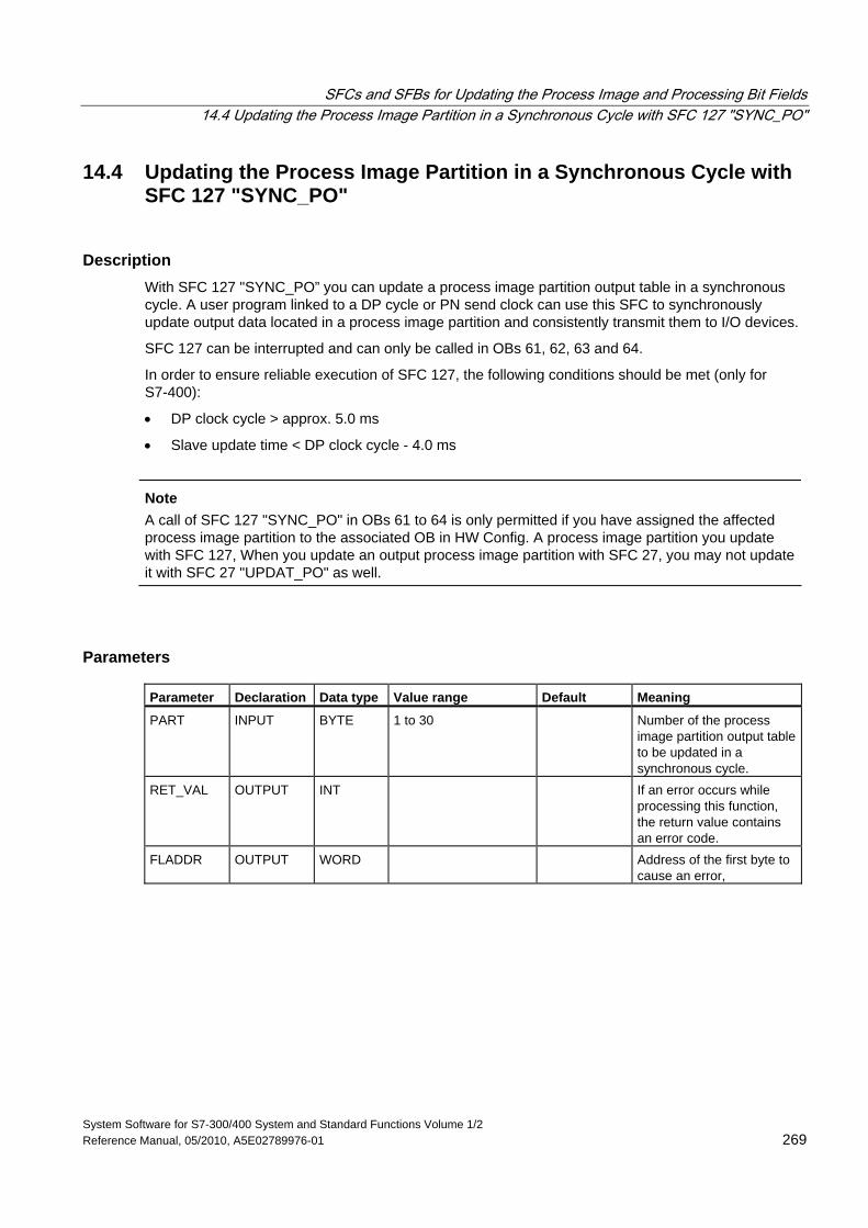
SFCs and SFBs for Updating the Process Image and Processing Bit Fields 14.4 Updating the Process Image Partition in a Synchronous Cycle with SFC 127 "SYNC_PO"
System Software for S7-300/400 System and Standard Functions Volume 1/2 Reference Manual, 05/2010, A5E02789976-01 269
14.4 Updating the Process Image Partition in a Synchronous Cycle with SFC 127 "SYNC_PO"
Description With SFC 127 "SYNC_PO” you can update a process image partition output table in a synchronous cycle. A user program linked to a DP cycle or PN send clock can use this SFC to synchronously update output data located in a process image partition and consistently transmit them to I/O devices.
SFC 127 can be interrupted and can only be called in OBs 61, 62, 63 and 64.
In order to ensure reliable execution of SFC 127, the following conditions should be met (only for S7-400):
• DP clock cycle > approx. 5.0 ms
• Slave update time < DP clock cycle - 4.0 ms
Note
A call of SFC 127 "SYNC_PO" in OBs 61 to 64 is only permitted if you have assigned the affected process image partition to the associated OB in HW Config. A process image partition you update with SFC 127, When you update an output process image partition with SFC 27, you may not update it with SFC 27 "UPDAT_PO" as well.
Parameters Parameter Declaration Data type Value range Default Meaning
PART INPUT BYTE 1 to 30 Number of the process image partition output table to be updated in a synchronous cycle.
RET_VAL OUTPUT INT If an error occurs while processing this function, the return value contains an error code.
FLADDR OUTPUT WORD Address of the first byte to cause an error,
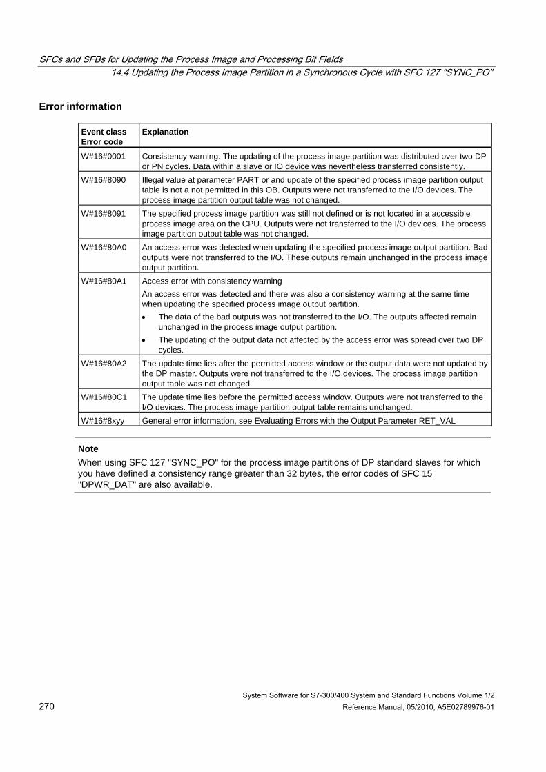
SFCs and SFBs for Updating the Process Image and Processing Bit Fields 14.4 Updating the Process Image Partition in a Synchronous Cycle with SFC 127 "SYNC_PO"
System Software for S7-300/400 System and Standard Functions Volume 1/2 270 Reference Manual, 05/2010, A5E02789976-01
Error information Event class Error code
Explanation
W#16#0001 Consistency warning. The updating of the process image partition was distributed over two DP or PN cycles. Data within a slave or IO device was nevertheless transferred consistently.
W#16#8090 Illegal value at parameter PART or and update of the specified process image partition output table is not a not permitted in this OB. Outputs were not transferred to the I/O devices. The process image partition output table was not changed.
W#16#8091 The specified process image partition was still not defined or is not located in a accessible process image area on the CPU. Outputs were not transferred to the I/O devices. The process image partition output table was not changed.
W#16#80A0 An access error was detected when updating the specified process image output partition. Bad outputs were not transferred to the I/O. These outputs remain unchanged in the process image output partition.
W#16#80A1 Access error with consistency warning An access error was detected and there was also a consistency warning at the same time when updating the specified process image output partition. • The data of the bad outputs was not transferred to the I/O. The outputs affected remain
unchanged in the process image output partition. • The updating of the output data not affected by the access error was spread over two DP
cycles. W#16#80A2 The update time lies after the permitted access window or the output data were not updated by
the DP master. Outputs were not transferred to the I/O devices. The process image partition output table was not changed.
W#16#80C1 The update time lies before the permitted access window. Outputs were not transferred to the I/O devices. The process image partition output table remains unchanged.
W#16#8xyy General error information, see Evaluating Errors with the Output Parameter RET_VAL
Note When using SFC 127 "SYNC_PO" for the process image partitions of DP standard slaves for which you have defined a consistency range greater than 32 bytes, the error codes of SFC 15 "DPWR_DAT" are also available.
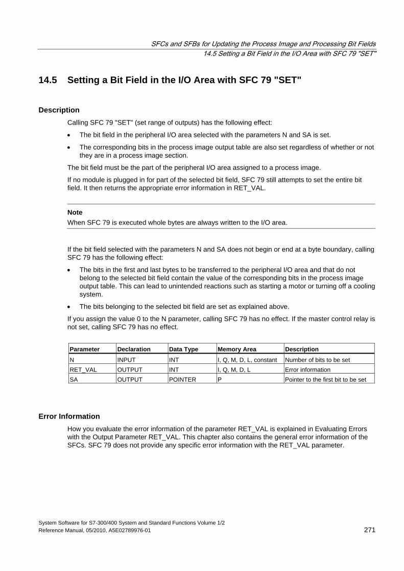
SFCs and SFBs for Updating the Process Image and Processing Bit Fields 14.5 Setting a Bit Field in the I/O Area with SFC 79 "SET"
System Software for S7-300/400 System and Standard Functions Volume 1/2 Reference Manual, 05/2010, A5E02789976-01 271
14.5 Setting a Bit Field in the I/O Area with SFC 79 "SET"
Description Calling SFC 79 "SET" (set range of outputs) has the following effect:
• The bit field in the peripheral I/O area selected with the parameters N and SA is set.
• The corresponding bits in the process image output table are also set regardless of whether or not they are in a process image section.
The bit field must be the part of the peripheral I/O area assigned to a process image.
If no module is plugged in for part of the selected bit field, SFC 79 still attempts to set the entire bit field. It then returns the appropriate error information in RET_VAL.
Note
When SFC 79 is executed whole bytes are always written to the I/O area.
If the bit field selected with the parameters N and SA does not begin or end at a byte boundary, calling SFC 79 has the following effect:
• The bits in the first and last bytes to be transferred to the peripheral I/O area and that do not belong to the selected bit field contain the value of the corresponding bits in the process image output table. This can lead to unintended reactions such as starting a motor or turning off a cooling system.
• The bits belonging to the selected bit field are set as explained above.
If you assign the value 0 to the N parameter, calling SFC 79 has no effect. If the master control relay is not set, calling SFC 79 has no effect.
Parameter Declaration Data Type Memory Area Description
N INPUT INT I, Q, M, D, L, constant Number of bits to be set RET_VAL OUTPUT INT I, Q, M, D, L Error information SA OUTPUT POINTER P Pointer to the first bit to be set
Error Information How you evaluate the error information of the parameter RET_VAL is explained in Evaluating Errors with the Output Parameter RET_VAL. This chapter also contains the general error information of the SFCs. SFC 79 does not provide any specific error information with the RET_VAL parameter.
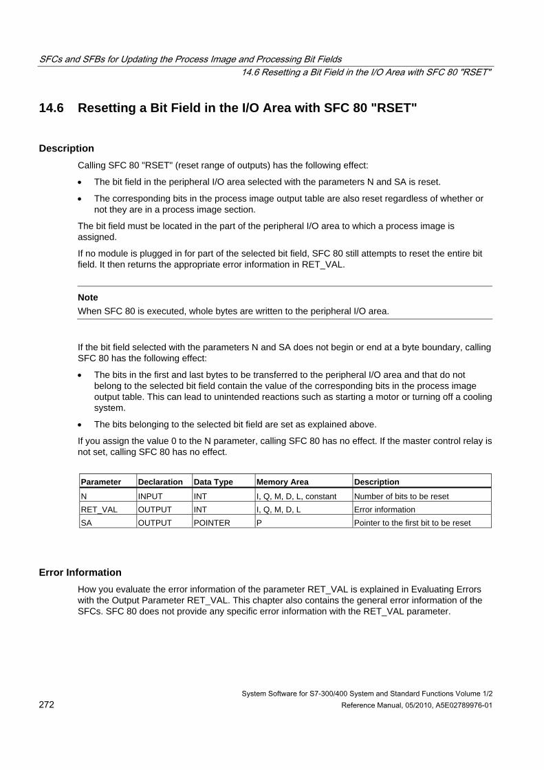
SFCs and SFBs for Updating the Process Image and Processing Bit Fields 14.6 Resetting a Bit Field in the I/O Area with SFC 80 "RSET"
System Software for S7-300/400 System and Standard Functions Volume 1/2 272 Reference Manual, 05/2010, A5E02789976-01
14.6 Resetting a Bit Field in the I/O Area with SFC 80 "RSET"
Description Calling SFC 80 "RSET" (reset range of outputs) has the following effect:
• The bit field in the peripheral I/O area selected with the parameters N and SA is reset.
• The corresponding bits in the process image output table are also reset regardless of whether or not they are in a process image section.
The bit field must be located in the part of the peripheral I/O area to which a process image is assigned.
If no module is plugged in for part of the selected bit field, SFC 80 still attempts to reset the entire bit field. It then returns the appropriate error information in RET_VAL.
Note
When SFC 80 is executed, whole bytes are written to the peripheral I/O area.
If the bit field selected with the parameters N and SA does not begin or end at a byte boundary, calling SFC 80 has the following effect:
• The bits in the first and last bytes to be transferred to the peripheral I/O area and that do not belong to the selected bit field contain the value of the corresponding bits in the process image output table. This can lead to unintended reactions such as starting a motor or turning off a cooling system.
• The bits belonging to the selected bit field are set as explained above.
If you assign the value 0 to the N parameter, calling SFC 80 has no effect. If the master control relay is not set, calling SFC 80 has no effect.
Parameter Declaration Data Type Memory Area Description
N INPUT INT I, Q, M, D, L, constant Number of bits to be reset RET_VAL OUTPUT INT I, Q, M, D, L Error information SA OUTPUT POINTER P Pointer to the first bit to be reset
Error Information How you evaluate the error information of the parameter RET_VAL is explained in Evaluating Errors with the Output Parameter RET_VAL. This chapter also contains the general error information of the SFCs. SFC 80 does not provide any specific error information with the RET_VAL parameter.
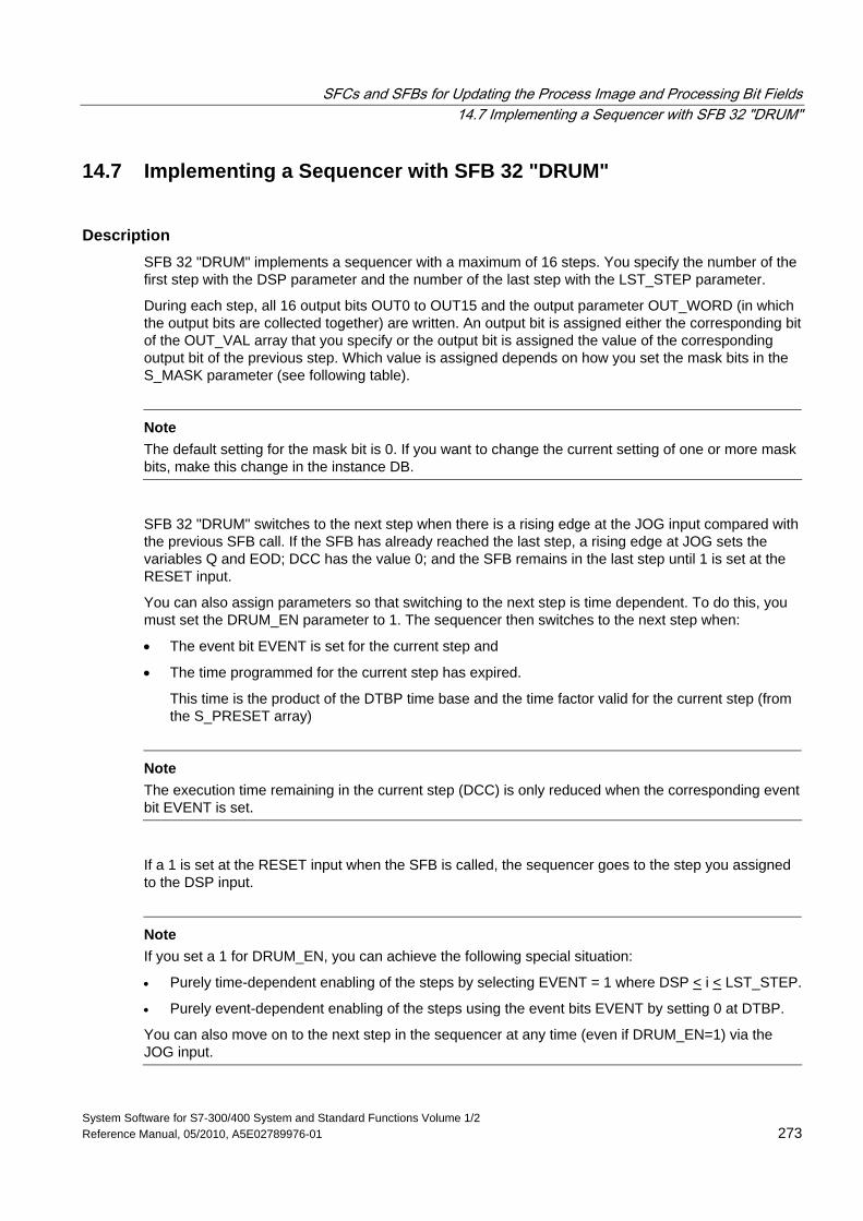
SFCs and SFBs for Updating the Process Image and Processing Bit Fields 14.7 Implementing a Sequencer with SFB 32 "DRUM"
System Software for S7-300/400 System and Standard Functions Volume 1/2 Reference Manual, 05/2010, A5E02789976-01 273
14.7 Implementing a Sequencer with SFB 32 "DRUM"
Description SFB 32 "DRUM" implements a sequencer with a maximum of 16 steps. You specify the number of the first step with the DSP parameter and the number of the last step with the LST_STEP parameter.
During each step, all 16 output bits OUT0 to OUT15 and the output parameter OUT_WORD (in which the output bits are collected together) are written. An output bit is assigned either the corresponding bit of the OUT_VAL array that you specify or the output bit is assigned the value of the corresponding output bit of the previous step. Which value is assigned depends on how you set the mask bits in the S_MASK parameter (see following table).
Note
The default setting for the mask bit is 0. If you want to change the current setting of one or more mask bits, make this change in the instance DB.
SFB 32 "DRUM" switches to the next step when there is a rising edge at the JOG input compared with the previous SFB call. If the SFB has already reached the last step, a rising edge at JOG sets the variables Q and EOD; DCC has the value 0; and the SFB remains in the last step until 1 is set at the RESET input.
You can also assign parameters so that switching to the next step is time dependent. To do this, you must set the DRUM_EN parameter to 1. The sequencer then switches to the next step when:
• The event bit EVENT is set for the current step and
• The time programmed for the current step has expired.
This time is the product of the DTBP time base and the time factor valid for the current step (from the S_PRESET array)
Note
The execution time remaining in the current step (DCC) is only reduced when the corresponding event bit EVENT is set.
If a 1 is set at the RESET input when the SFB is called, the sequencer goes to the step you assigned to the DSP input.
Note
If you set a 1 for DRUM_EN, you can achieve the following special situation:
• Purely time-dependent enabling of the steps by selecting EVENT = 1 where DSP < i < LST_STEP.
• Purely event-dependent enabling of the steps using the event bits EVENT by setting 0 at DTBP.
You can also move on to the next step in the sequencer at any time (even if DRUM_EN=1) via the JOG input.
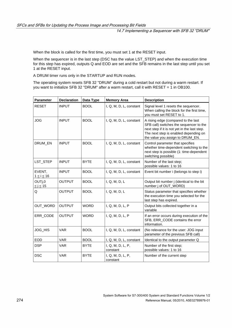
SFCs and SFBs for Updating the Process Image and Processing Bit Fields 14.7 Implementing a Sequencer with SFB 32 "DRUM"
System Software for S7-300/400 System and Standard Functions Volume 1/2 274 Reference Manual, 05/2010, A5E02789976-01
When the block is called for the first time, you must set 1 at the RESET input.
When the sequencer is in the last step (DSC has the value LST_STEP) and when the execution time for this step has expired, outputs Q and EOD are set and the SFB remains in the last step until you set 1 at the RESET input.
A DRUM timer runs only in the STARTUP and RUN modes.
The operating system resets SFB 32 "DRUM" during a cold restart but not during a warm restart. If you want to initialize SFB 32 "DRUM" after a warm restart, call it with RESET = 1 in OB100.
Parameter Declaration Data Type Memory Area Description
RESET INPUT BOOL I, Q, M, D, L, constant Signal level 1 resets the sequencer. When calling the block for the first time, you must set RESET to 1.
JOG INPUT BOOL I, Q, M, D, L, constant A rising edge (compared to the last SFB call) switches the sequencer to the next step if it is not yet in the last step. The next step is enabled depending on the value you assign to DRUM_EN.
DRUM_EN INPUT BOOL I, Q, M, D, L, constant Control parameter that specifies whether time-dependent switching to the next step is possible (1: time-dependent switching possible)
LST_STEP INPUT BYTE I, Q, M, D, L, constant Number of the last step; possible values: 1 to 16
EVENT, 1 < i < 16
INPUT BOOL I, Q, M, D, L, constant Event bit number i (belongs to step i)
OUTj,0 < j < 15
OUTPUT BOOL I, Q, M, D, L Output bit number j (identical to the bit number j of OUT_WORD)
Q OUTPUT BOOL I, Q, M, D, L Status parameter that specifies whether the execution time you selected for the last step has expired.
OUT_WORD OUTPUT WORD I, Q, M, D, L, P Output bits collected together in a variable
ERR_CODE OUTPUT WORD I, Q, M, D, L, P If an error occurs during execution of the SFB, ERR_CODE contains the error information.
JOG_HIS VAR BOOL I, Q, M, D, L, constant (No relevance for the user: JOG input parameter of the previous SFB call)
EOD VAR BOOL I, Q, M, D, L, constant Identical to the output parameter Q DSP VAR BYTE I, Q, M, D, L, P,
constant Number of the first step; possible values: 1 to 16
DSC VAR BYTE I, Q, M, D, L, P, constant
Number of the current step
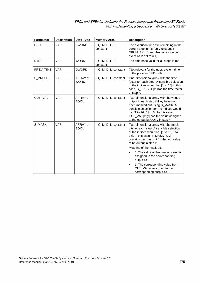
SFCs and SFBs for Updating the Process Image and Processing Bit Fields 14.7 Implementing a Sequencer with SFB 32 "DRUM"
System Software for S7-300/400 System and Standard Functions Volume 1/2 Reference Manual, 05/2010, A5E02789976-01 275
Parameter Declaration Data Type Memory Area Description
DCC VAR DWORD I, Q, M, D, L, P, constant
The execution time still remaining in the current step in ms (only relevant if DRUM_EN = 1 and the corresponding event bit is set to = 1)
DTBP VAR WORD I, Q, M, D, L, P, constant
The time base valid for all steps in ms
PREV_TIME VAR DWORD I, Q, M, D, L, constant (Not relevant for the user: system time of the previous SFB call)
S_PRESET VAR ARRAY of WORD
I, Q, M, D, L, constant One-dimensional array with the time factor for each step. A sensible selection of the indices would be: [1 to 16].In this case, S_PRESET [x] has the time factor of step x.
OUT_VAL VAR ARRAY of BOOL
I, Q, M, D, L, constant Two-dimensional array with the values output in each step if they have not been masked out using S_MASK. A sensible selection for the indices would be: [1 to 16, 0 to 15]. In this case, OUT_VAL [x, y] has the value assigned to the output bit OUTy in step x.
S_MASK VAR ARRAY of BOOL
I, Q, M, D, L, constant Two-dimensional array with the mask bits for each step. A sensible selection of the indices would be: [1 to 16, 0 to 15]. In this case, S_MASK [x, y] contains the mask bit for the y-th value to be output in step x. Meaning of the mask bits: • 0: The value of the previous step is
assigned to the corresponding output bit.
• 1: The corresponding value from OUT_VAL is assigned to the corresponding output bit.
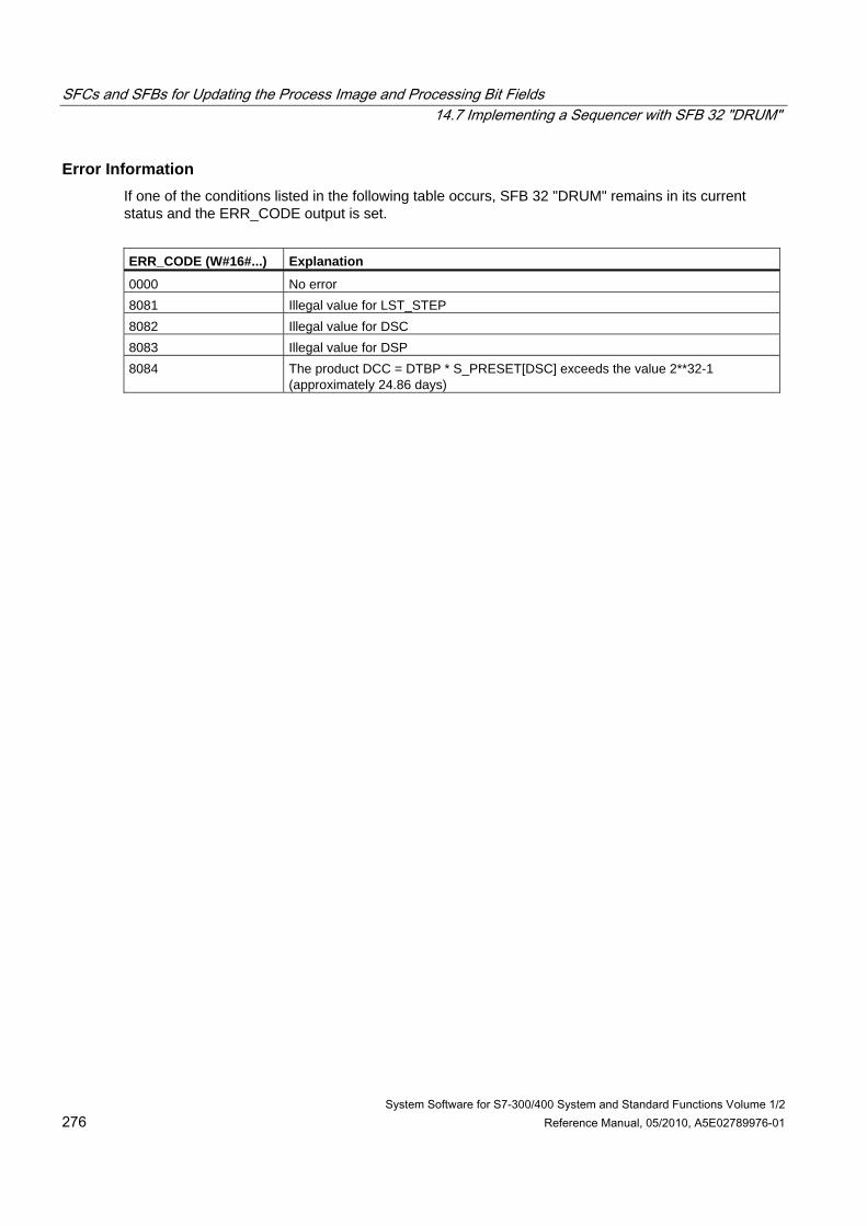
SFCs and SFBs for Updating the Process Image and Processing Bit Fields 14.7 Implementing a Sequencer with SFB 32 "DRUM"
System Software for S7-300/400 System and Standard Functions Volume 1/2 276 Reference Manual, 05/2010, A5E02789976-01
Error Information If one of the conditions listed in the following table occurs, SFB 32 "DRUM" remains in its current status and the ERR_CODE output is set.
ERR_CODE (W#16#...) Explanation
0000 No error 8081 Illegal value for LST_STEP 8082 Illegal value for DSC 8083 Illegal value for DSP 8084 The product DCC = DTBP * S_PRESET[DSC] exceeds the value 2**32-1
(approximately 24.86 days)
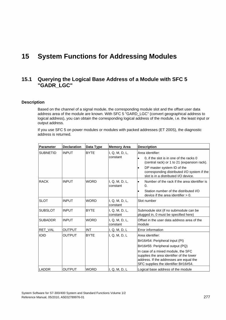
System Software for S7-300/400 System and Standard Functions Volume 1/2 Reference Manual, 05/2010, A5E02789976-01 277
15 System Functions for Addressing Modules
15.1 Querying the Logical Base Address of a Module with SFC 5 "GADR_LGC"
Description Based on the channel of a signal module, the corresponding module slot and the offset user data address area of the module are known. With SFC 5 "GARD_LGC" (convert geographical address to logical address), you can obtain the corresponding logical address of the module, i.e. the least input or output address.
If you use SFC 5 on power modules or modules with packed addresses (ET 200S), the diagnostic address is returned.
Parameter Declaration Data Type Memory Area Description
SUBNETID INPUT BYTE I, Q, M, D, L, constant
Area identifier: • 0, if the slot is in one of the racks 0
(central rack) or 1 to 21 (expansion rack). • DP master system ID of the
corresponding distributed I/O system if the slot is in a distributed I/O device.
RACK INPUT WORD I, Q, M, D, L, constant
• Number of the rack if the area identifier is 0.
• Station number of the distributed I/O device if the area identifier > 0.
SLOT INPUT WORD I, Q, M, D, L, constant
Slot number
SUBSLOT INPUT BYTE I, Q, M, D, L, constant
Submodule slot (if no submodule can be plugged in, 0 must be specified here)
SUBADDR INPUT WORD I, Q, M, D, L, constant
Offset in the user data address area of the module
RET_VAL OUTPUT INT I, Q, M, D, L Error information IOID OUTPUT BYTE I, Q, M, D, L Area identifier:
B#16#54: Peripheral input (PI) B#16#55: Peripheral output (PQ) In case of a mixed module, the SFC supplies the area identifier of the lower address. If the addresses are equal the SFC supplies the identifier B#16#54.
LADDR OUTPUT WORD I, Q, M, D, L Logical base address of the module
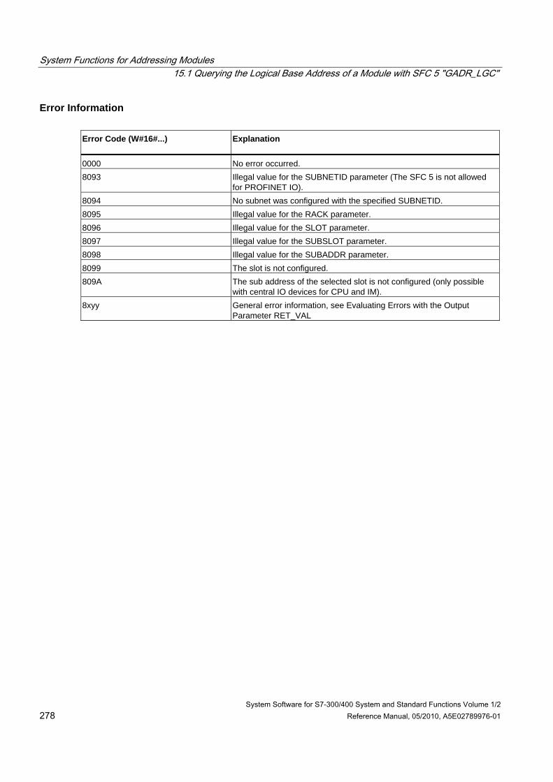
System Functions for Addressing Modules 15.1 Querying the Logical Base Address of a Module with SFC 5 "GADR_LGC"
System Software for S7-300/400 System and Standard Functions Volume 1/2 278 Reference Manual, 05/2010, A5E02789976-01
Error Information Error Code (W#16#...) Explanation
0000 No error occurred. 8093 Illegal value for the SUBNETID parameter (The SFC 5 is not allowed
for PROFINET IO). 8094 No subnet was configured with the specified SUBNETID. 8095 Illegal value for the RACK parameter. 8096 Illegal value for the SLOT parameter. 8097 Illegal value for the SUBSLOT parameter. 8098 Illegal value for the SUBADDR parameter. 8099 The slot is not configured. 809A The sub address of the selected slot is not configured (only possible
with central IO devices for CPU and IM). 8xyy General error information, see Evaluating Errors with the Output
Parameter RET_VAL
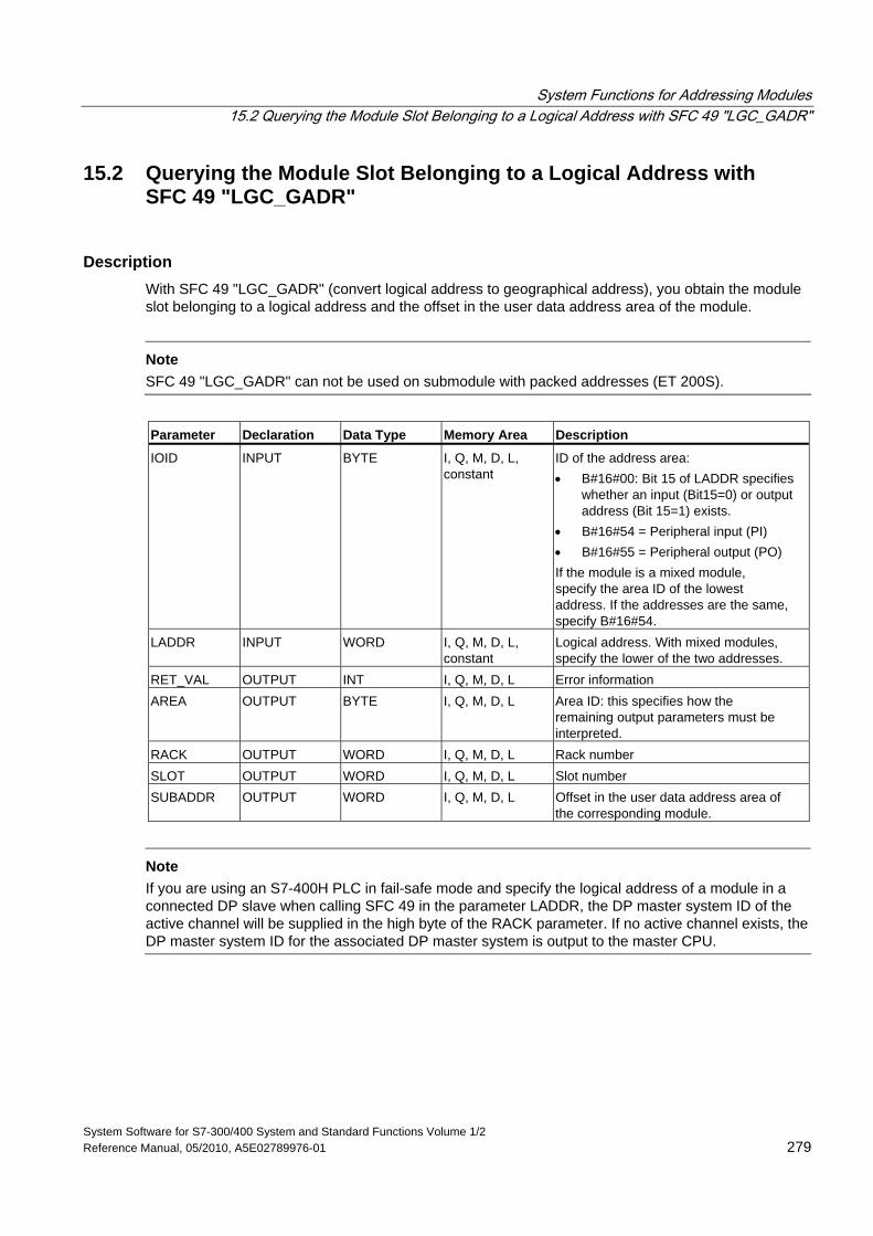
System Functions for Addressing Modules 15.2 Querying the Module Slot Belonging to a Logical Address with SFC 49 "LGC_GADR"
System Software for S7-300/400 System and Standard Functions Volume 1/2 Reference Manual, 05/2010, A5E02789976-01 279
15.2 Querying the Module Slot Belonging to a Logical Address with SFC 49 "LGC_GADR"
Description With SFC 49 "LGC_GADR" (convert logical address to geographical address), you obtain the module slot belonging to a logical address and the offset in the user data address area of the module.
Note
SFC 49 "LGC_GADR" can not be used on submodule with packed addresses (ET 200S).
Parameter Declaration Data Type Memory Area Description
IOID INPUT BYTE I, Q, M, D, L, constant
ID of the address area: • B#16#00: Bit 15 of LADDR specifies
whether an input (Bit15=0) or output address (Bit 15=1) exists.
• B#16#54 = Peripheral input (PI) • B#16#55 = Peripheral output (PO) If the module is a mixed module, specify the area ID of the lowest address. If the addresses are the same, specify B#16#54.
LADDR INPUT WORD I, Q, M, D, L, constant
Logical address. With mixed modules, specify the lower of the two addresses.
RET_VAL OUTPUT INT I, Q, M, D, L Error information AREA OUTPUT BYTE I, Q, M, D, L Area ID: this specifies how the
remaining output parameters must be interpreted.
RACK OUTPUT WORD I, Q, M, D, L Rack number SLOT OUTPUT WORD I, Q, M, D, L Slot number SUBADDR OUTPUT WORD I, Q, M, D, L Offset in the user data address area of
the corresponding module.
Note
If you are using an S7-400H PLC in fail-safe mode and specify the logical address of a module in a connected DP slave when calling SFC 49 in the parameter LADDR, the DP master system ID of the active channel will be supplied in the high byte of the RACK parameter. If no active channel exists, the DP master system ID for the associated DP master system is output to the master CPU.

System Functions for Addressing Modules 15.2 Querying the Module Slot Belonging to a Logical Address with SFC 49 "LGC_GADR"
System Software for S7-300/400 System and Standard Functions Volume 1/2 280 Reference Manual, 05/2010, A5E02789976-01
Output Parameter AREA The output parameter AREA specifies how the output parameters RACK, SLOT and SUBADDR must be interpreted (see following table).
Value of AREA System Meaning of RACK, SLOT and SUBADDR
0 S7-400 RACK : Module rack no. SLOT : Slot no. SUBADDR : Difference between logical address and logical base address
1 S7-300 RACK: Module rack no. SLOT : Slot no. SUBADDR : Difference between logical address and logical base address
2 DP RACK: (low byte) Station number RACK : (high byte) DP Master system ID SLOT : Slot no. in the station SUBADDR : Offset in the user data address area of the corresponding module.
3 S5 P area RACK: Module rack no. SLOT : Slot no. of the adaptation capsule SUBADDR : Address in the S5 x range
4 S5 O area RACK: Module rack no. SLOT : Slot no. of the adaptation capsule SUBADDR : Address in the S5 x range
5 S5 IM3 area RACK: Module rack no. SLOT : Slot no. of the adaptation capsule SUBADDR : Address in the S5 x range
6 S5 IM4 area RACK: Module rack no. SLOT : Slot no. of the adaptation capsule SUBADDR : Address in the S5 x range
Error Information Error Code (W#16#...) Explanation
0000 No error occurred. 8090 Specified logical address invalid or illegal value for the IOID parameter 8093 This SFC is invalid for the module selected by means of IOID and LADDR. 8xyy General error information, see Evaluating Errors with the Output Parameter
RET_VAL
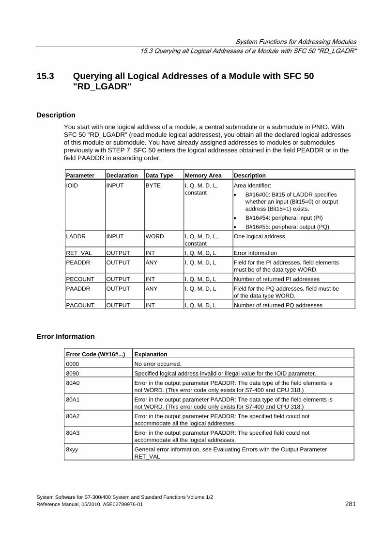
System Functions for Addressing Modules 15.3 Querying all Logical Addresses of a Module with SFC 50 "RD_LGADR"
System Software for S7-300/400 System and Standard Functions Volume 1/2 Reference Manual, 05/2010, A5E02789976-01 281
15.3 Querying all Logical Addresses of a Module with SFC 50 "RD_LGADR"
Description You start with one logical address of a module, a central submodule or a submodule in PNIO. With SFC 50 "RD_LGADR" (read module logical addresses), you obtain all the declared logical addresses of this module or submodule. You have already assigned addresses to modules or submodules previously with STEP 7. SFC 50 enters the logical addresses obtained in the field PEADDR or in the field PAADDR in ascending order. Parameter Declaration Data Type Memory Area Description
IOID INPUT BYTE I, Q, M, D, L, constant
Area identifier: • B#16#00: Bit15 of LADDR specifies
whether an input (Bit15=0) or output address (Bit15=1) exists.
• B#16#54: peripheral input (PI) • B#16#55: peripheral output (PQ)
LADDR INPUT WORD I, Q, M, D, L, constant
One logical address
RET_VAL OUTPUT INT I, Q, M, D, L Error information PEADDR OUTPUT ANY I, Q, M, D, L Field for the PI addresses, field elements
must be of the data type WORD. PECOUNT OUTPUT INT I, Q, M, D, L Number of returned PI addresses PAADDR OUTPUT ANY I, Q, M, D, L Field for the PQ addresses, field must be
of the data type WORD. PACOUNT OUTPUT INT I, Q, M, D, L Number of returned PQ addresses
Error Information Error Code (W#16#...) Explanation 0000 No error occurred. 8090 Specified logical address invalid or illegal value for the IOID parameter. 80A0 Error in the output parameter PEADDR: The data type of the field elements is
not WORD. (This error code only exists for S7-400 and CPU 318.) 80A1 Error in the output parameter PAADDR: The data type of the field elements is
not WORD. (This error code only exists for S7-400 and CPU 318.) 80A2 Error in the output parameter PEADDR: The specified field could not
accommodate all the logical addresses. 80A3 Error in the output parameter PAADDR: The specified field could not
accommodate all the logical addresses. 8xyy General error information, see Evaluating Errors with the Output Parameter
RET_VAL
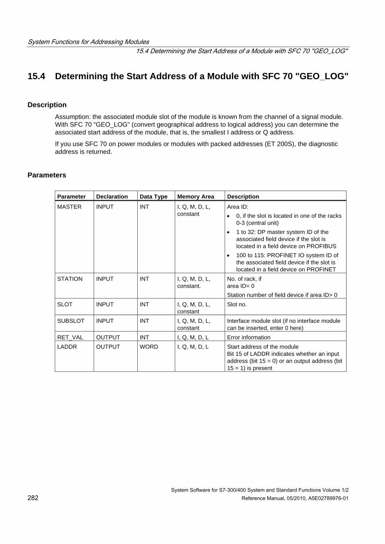
System Functions for Addressing Modules 15.4 Determining the Start Address of a Module with SFC 70 "GEO_LOG"
System Software for S7-300/400 System and Standard Functions Volume 1/2 282 Reference Manual, 05/2010, A5E02789976-01
15.4 Determining the Start Address of a Module with SFC 70 "GEO_LOG"
Description Assumption: the associated module slot of the module is known from the channel of a signal module. With SFC 70 "GEO_LOG" (convert geographical address to logical address) you can determine the associated start address of the module, that is, the smallest I address or Q address.
If you use SFC 70 on power modules or modules with packed addresses (ET 200S), the diagnostic address is returned.
Parameters Parameter Declaration Data Type Memory Area Description
MASTER INPUT INT I, Q, M, D, L, constant
Area ID: • 0, if the slot is located in one of the racks
0-3 (central unit) • 1 to 32: DP master system ID of the
associated field device if the slot is located in a field device on PROFIBUS
• 100 to 115: PROFINET IO system ID of the associated field device if the slot is located in a field device on PROFINET
STATION INPUT INT I, Q, M, D, L, constant.
No. of rack, if area ID= 0 Station number of field device if area ID> 0
SLOT INPUT INT I, Q, M, D, L, constant
Slot no.
SUBSLOT INPUT INT I, Q, M, D, L, constant
Interface module slot (if no interface module can be inserted, enter 0 here)
RET_VAL OUTPUT INT I, Q, M, D, L Error information LADDR OUTPUT WORD I, Q, M, D, L Start address of the module
Bit 15 of LADDR indicates whether an input address (bit 15 = 0) or an output address (bit 15 = 1) is present
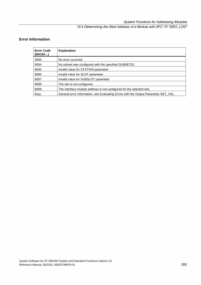
System Functions for Addressing Modules 15.4 Determining the Start Address of a Module with SFC 70 "GEO_LOG"
System Software for S7-300/400 System and Standard Functions Volume 1/2 Reference Manual, 05/2010, A5E02789976-01 283
Error Information Error Code (W#16#...)
Explanation
0000 No error occurred. 8094 No subnet was configured with the specified SUBNETID. 8095 Invalid value for STATION parameter 8096 Invalid value for SLOT parameter 8097 Invalid value for SUBSLOT parameter 8099 The slot is not configured. 809A The interface module address is not configured for the selected slot. 8xyy General error information, see Evaluating Errors with the Output Parameter RET_VAL
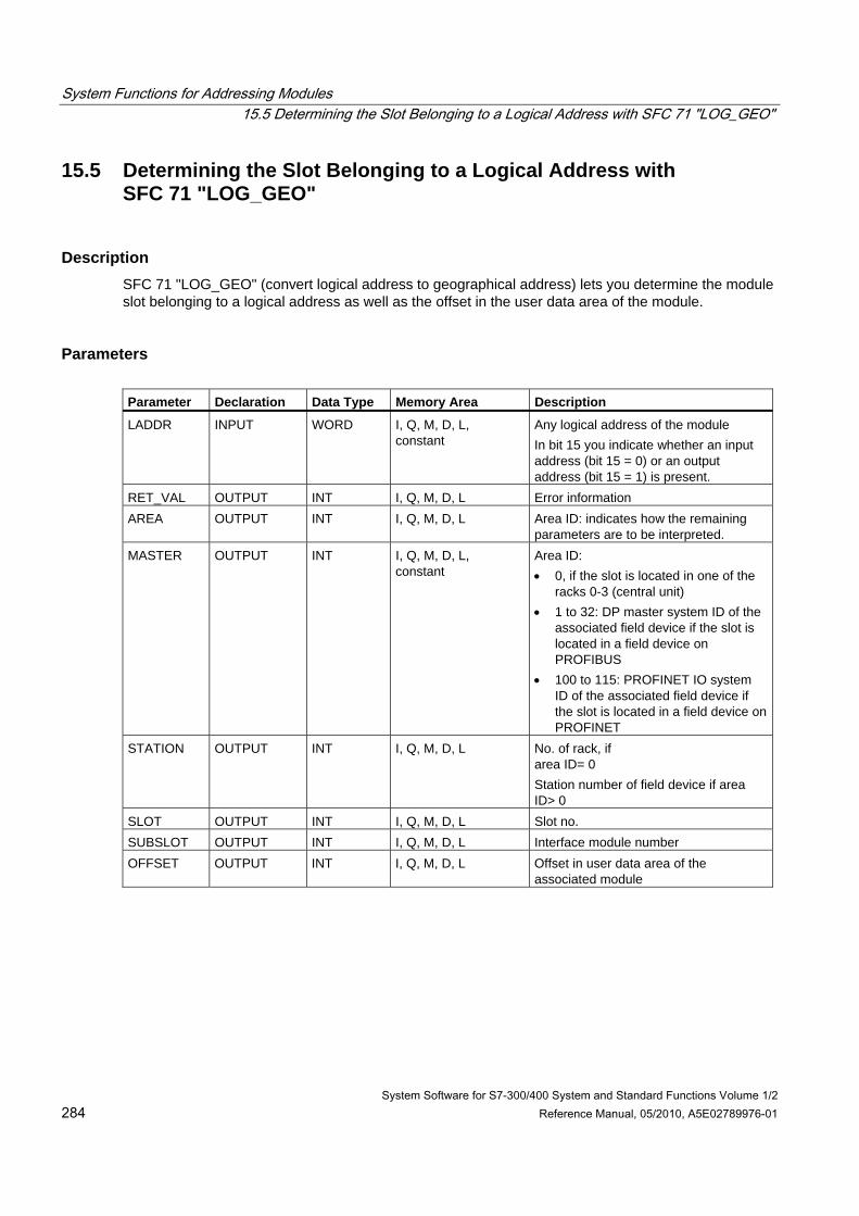
System Functions for Addressing Modules 15.5 Determining the Slot Belonging to a Logical Address with SFC 71 "LOG_GEO"
System Software for S7-300/400 System and Standard Functions Volume 1/2 284 Reference Manual, 05/2010, A5E02789976-01
15.5 Determining the Slot Belonging to a Logical Address with SFC 71 "LOG_GEO"
Description SFC 71 "LOG_GEO" (convert logical address to geographical address) lets you determine the module slot belonging to a logical address as well as the offset in the user data area of the module.
Parameters Parameter Declaration Data Type Memory Area Description
LADDR INPUT WORD I, Q, M, D, L, constant
Any logical address of the module In bit 15 you indicate whether an input address (bit 15 = 0) or an output address (bit 15 = 1) is present.
RET_VAL OUTPUT INT I, Q, M, D, L Error information AREA OUTPUT INT I, Q, M, D, L Area ID: indicates how the remaining
parameters are to be interpreted. MASTER OUTPUT INT I, Q, M, D, L,
constant Area ID: • 0, if the slot is located in one of the
racks 0-3 (central unit) • 1 to 32: DP master system ID of the
associated field device if the slot is located in a field device on PROFIBUS
• 100 to 115: PROFINET IO system ID of the associated field device if the slot is located in a field device on PROFINET
STATION OUTPUT INT I, Q, M, D, L No. of rack, if area ID= 0 Station number of field device if area ID> 0
SLOT OUTPUT INT I, Q, M, D, L Slot no. SUBSLOT OUTPUT INT I, Q, M, D, L Interface module number OFFSET OUTPUT INT I, Q, M, D, L Offset in user data area of the
associated module
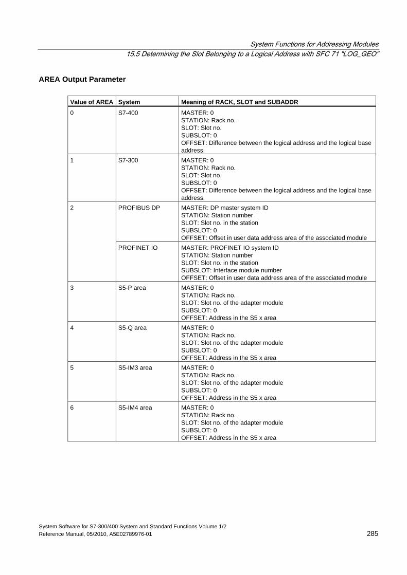
System Functions for Addressing Modules 15.5 Determining the Slot Belonging to a Logical Address with SFC 71 "LOG_GEO"
System Software for S7-300/400 System and Standard Functions Volume 1/2 Reference Manual, 05/2010, A5E02789976-01 285
AREA Output Parameter Value of AREA System Meaning of RACK, SLOT and SUBADDR
0 S7-400 MASTER: 0 STATION: Rack no. SLOT: Slot no. SUBSLOT: 0 OFFSET: Difference between the logical address and the logical base address.
1 S7-300 MASTER: 0 STATION: Rack no. SLOT: Slot no. SUBSLOT: 0 OFFSET: Difference between the logical address and the logical base address.
PROFIBUS DP
MASTER: DP master system ID STATION: Station number SLOT: Slot no. in the station SUBSLOT: 0 OFFSET: Offset in user data address area of the associated module
2
PROFINET IO MASTER: PROFINET IO system ID STATION: Station number SLOT: Slot no. in the station SUBSLOT: Interface module number OFFSET: Offset in user data address area of the associated module
3 S5-P area MASTER: 0 STATION: Rack no. SLOT: Slot no. of the adapter module SUBSLOT: 0 OFFSET: Address in the S5 x area
4 S5-Q area MASTER: 0 STATION: Rack no. SLOT: Slot no. of the adapter module SUBSLOT: 0 OFFSET: Address in the S5 x area
5 S5-IM3 area MASTER: 0 STATION: Rack no. SLOT: Slot no. of the adapter module SUBSLOT: 0 OFFSET: Address in the S5 x area
6 S5-IM4 area MASTER: 0 STATION: Rack no. SLOT: Slot no. of the adapter module SUBSLOT: 0 OFFSET: Address in the S5 x area
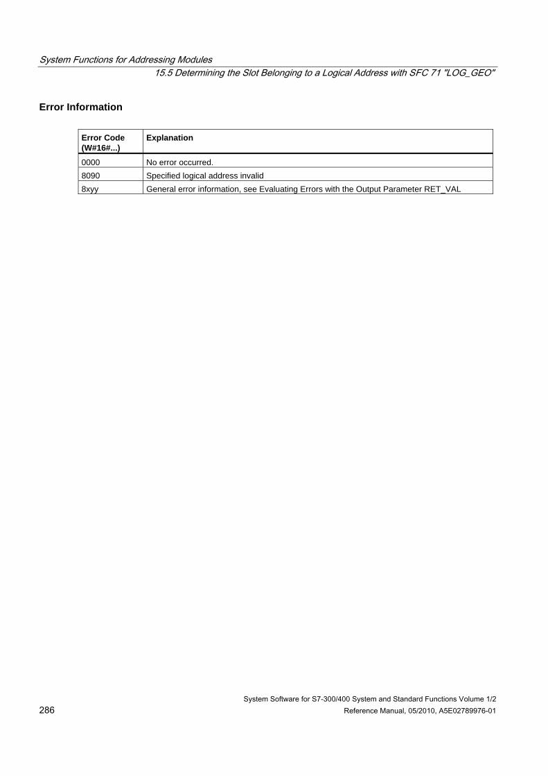
System Functions for Addressing Modules 15.5 Determining the Slot Belonging to a Logical Address with SFC 71 "LOG_GEO"
System Software for S7-300/400 System and Standard Functions Volume 1/2 286 Reference Manual, 05/2010, A5E02789976-01
Error Information Error Code (W#16#...)
Explanation
0000 No error occurred. 8090 Specified logical address invalid 8xyy General error information, see Evaluating Errors with the Output Parameter RET_VAL
System Software for S7-300/400 System and Standard Functions Volume 1/2 Reference Manual, 05/2010, A5E02789976-01 287
16 SFCs for Distributed I/Os or PROFINET IO
16.1 Triggering a Hardware Interrupt on the DP Master with SFC 7 "DP_PRAL"
Description With SFC 7 "DP_PRAL," you trigger a hardware interrupt on the DP master from the user program of an intelligent slave. This interrupt starts OB40 on the DP master.
Using the input parameter AL_INFO, you can identify the cause of the hardware interrupt. This interrupt identifier is transferred to the DP master and you can evaluate the identifier in OB40 (variable OB40_POINT_ADDR).
The requested hardware interrupt is uniquely specified by the input parameters IOID and LADDR. For each configured address area in the transfer memory, you can trigger exactly one hardware interrupt at any time.
How the SFC Operates SFC 7 "DP_PRAL" operates asynchronously, in other words, it is executed over several SFC calls. You start the hardware interrupt request by calling SFC 7 with REQ=1.
The status of the job is indicated by the output parameters RET_VAL and BUSY, see Meaning of the Parameters REQ, RET_VAL and BUSY with Asynchronous SFCs. The job is completed when execution of OB40 is completed on the DP master.
Note
If you operate the DP slave as a standard slave, the job is completed as soon as the diagnostic frame is obtained by the DP master.
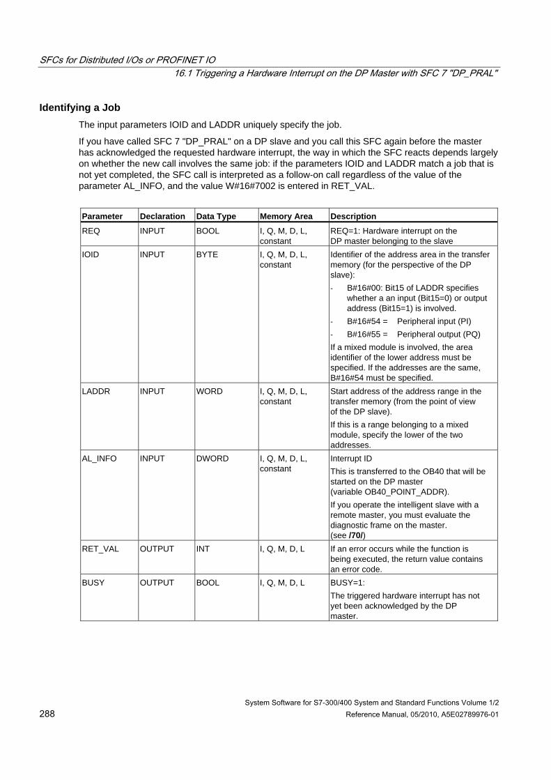
SFCs for Distributed I/Os or PROFINET IO 16.1 Triggering a Hardware Interrupt on the DP Master with SFC 7 "DP_PRAL"
System Software for S7-300/400 System and Standard Functions Volume 1/2 288 Reference Manual, 05/2010, A5E02789976-01
Identifying a Job The input parameters IOID and LADDR uniquely specify the job.
If you have called SFC 7 "DP_PRAL" on a DP slave and you call this SFC again before the master has acknowledged the requested hardware interrupt, the way in which the SFC reacts depends largely on whether the new call involves the same job: if the parameters IOID and LADDR match a job that is not yet completed, the SFC call is interpreted as a follow-on call regardless of the value of the parameter AL_INFO, and the value W#16#7002 is entered in RET_VAL.
Parameter Declaration Data Type Memory Area Description
REQ INPUT BOOL I, Q, M, D, L, constant
REQ=1: Hardware interrupt on the DP master belonging to the slave
IOID INPUT BYTE I, Q, M, D, L, constant
Identifier of the address area in the transfer memory (for the perspective of the DP slave): - B#16#00: Bit15 of LADDR specifies
whether a an input (Bit15=0) or output address (Bit15=1) is involved.
- B#16#54 = Peripheral input (PI) - B#16#55 = Peripheral output (PQ) If a mixed module is involved, the area identifier of the lower address must be specified. If the addresses are the same, B#16#54 must be specified.
LADDR INPUT WORD I, Q, M, D, L, constant
Start address of the address range in the transfer memory (from the point of view of the DP slave). If this is a range belonging to a mixed module, specify the lower of the two addresses.
AL_INFO INPUT DWORD I, Q, M, D, L, constant
Interrupt ID This is transferred to the OB40 that will be started on the DP master (variable OB40_POINT_ADDR). If you operate the intelligent slave with a remote master, you must evaluate the diagnostic frame on the master. (see /70/)
RET_VAL OUTPUT INT I, Q, M, D, L If an error occurs while the function is being executed, the return value contains an error code.
BUSY OUTPUT BOOL I, Q, M, D, L BUSY=1: The triggered hardware interrupt has not yet been acknowledged by the DP master.
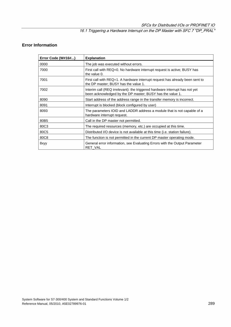
SFCs for Distributed I/Os or PROFINET IO 16.1 Triggering a Hardware Interrupt on the DP Master with SFC 7 "DP_PRAL"
System Software for S7-300/400 System and Standard Functions Volume 1/2 Reference Manual, 05/2010, A5E02789976-01 289
Error Information Error Code (W#16#...) Explanation
0000 The job was executed without errors. 7000 First call with REQ=0. No hardware interrupt request is active; BUSY has
the value 0. 7001 First call with REQ=1. A hardware interrupt request has already been sent to
the DP master; BUSY has the value 1. 7002 Interim call (REQ irrelevant): the triggered hardware interrupt has not yet
been acknowledged by the DP master; BUSY has the value 1. 8090 Start address of the address range in the transfer memory is incorrect. 8091 Interrupt is blocked (block configured by user) 8093 The parameters IOID and LADDR address a module that is not capable of a
hardware interrupt request. 80B5 Call in the DP master not permitted. 80C3 The required resources (memory, etc.) are occupied at this time. 80C5 Distributed I/O device is not available at this time (i.e. station failure). 80C8 The function is not permitted in the current DP master operating mode. 8xyy General error information, see Evaluating Errors with the Output Parameter
RET_VAL
SFCs for Distributed I/Os or PROFINET IO 16.2 Synchronizing Groups of DP Slaves with SFC 11 "DPSYC_FR"
System Software for S7-300/400 System and Standard Functions Volume 1/2 290 Reference Manual, 05/2010, A5E02789976-01
16.2 Synchronizing Groups of DP Slaves with SFC 11 "DPSYC_FR"
Description With SFC 11 "DPSYC_FR," you can synchronize one or more groups of DP slaves.
The function involves sending one of the control commands below or a combination of them to the relevant groups:
• SYNC (simultaneous output and freezing of output states on the DP slaves)
• UNSYNC (cancels the SYNC control command)
• FREEZE (freeze the input states on the DP slaves read in the frozen inputs)
• UNFREEZE (cancels the FREEZE control command)
Note
Note that the control commands SYNC and FREEZE also remain valid when you perform a restart/warm restart.
Please note also that you may initiate only one SYNC-/UNSYNC request or only one FREEZE/UNFREEZE request at a given time.
Requirements Before you send the control commands listed above, you must assign the DP slaves to groups using STEP 7 (see /231/). You must know which DP slave is assigned to which group with which number and know the reactions of the various groups to SYNC/FREEZE.
How the SFC Operates SFC 11 "DPSYC_FR" is an asynchronous SFC; in other words, its execution takes several SFC calls. You start the job by calling SFC 11 with REQ=1.
The status of the job is indicated by the output parameters RET_VAL and BUSY, also refer to Meaning of the Parameters REQ, RET_VAL and BUSY with Asynchronous SFCs.
Identifying a Job If you have triggered a SYNC/FREEZE job and called SFC 11 again before the first job was completed, the response of the SFC depends on whether the new call is for the same job. If the input parameters LADDR, GROUP and MODE match, the SFC call is interpreted as a follow-on call.
SFCs for Distributed I/Os or PROFINET IO 16.2 Synchronizing Groups of DP Slaves with SFC 11 "DPSYC_FR"
System Software for S7-300/400 System and Standard Functions Volume 1/2 Reference Manual, 05/2010, A5E02789976-01 291
Writing Outputs of DP Modules The writing of outputs of DP modules is triggered as follows:
• By transfer commands to the DP I/Os,
• By writing the process image output table to the modules (by the operating system at the end of OB1 or by calling SFC 27 "UPDAT_PO"),
• By calling SFC 15 "DPWR_DAT."
In normal operation, the DP master transfers the output bytes cyclically (within the cycle of the PROFIBUS DP bus) to the outputs of the DP slaves.
If you want to have certain output data (possibly distributed on several slaves) applied to the outputs to the process at exactly the same time, you can send the SYNC command to the relevant DP master using SFC 11 "DPSYC_FR."
What are the Effects of SYNC? With the SYNC control command, the DP slaves of the selected groups are switched to the Sync mode. In other words, the DP master transfers the current output data and instructs the DP slaves involved to freeze their outputs. With the following output frames, the DP slaves enter the output data in an internal buffer and the state of the outputs remains unchanged.
Following each SYNC control command, the DP slaves of the selected groups apply the output data of their internal buffer to the outputs to the process.
The outputs are only updated cyclically again when you send the UNSYNC control command using SFC 11 "DPSYC_FR."
Note
If the DP slaves of the selected group(s) are not currently connected to the network or have failed when the control command has been sent, they will not be switched to SYNC mode. This information will not be communicated in the return value of the SFC.
Reading Input Data of DP Modules The input data of the DP modules are read as follows:
• Using load commands to the DP I/Os,
• When the process image input table is updated (by the operating system at the start of OB1 or by calling SFC 26 "UPDAT_PI"),
• By calling SFC 14 "DPRD_DAT."
In normal operation, the DP master receives this input data cyclically (within the cycle of the PROFIBUS DP bus) from its DP slaves and makes them available to the CPU.
If you want to have certain input data (possibly distributed on several slaves) to be read from the process at exactly the same time, send the FREEZE control command to the relevant DP master using SFC 11 "DPSYC_FR."
SFCs for Distributed I/Os or PROFINET IO 16.2 Synchronizing Groups of DP Slaves with SFC 11 "DPSYC_FR"
System Software for S7-300/400 System and Standard Functions Volume 1/2 292 Reference Manual, 05/2010, A5E02789976-01
What are the Effects of FREEZE? With the FREEZE control command, the DP slaves involved are switched to the Freeze mode, in other words the DP master instructs the DP slaves to freeze the current state of the inputs. It then transfers the frozen data to the input area of the CPU.
Following each FREEZE control command, the DP slaves freeze the state of their inputs again.
The DP master only receives the current state of the inputs cyclically again after you have sent the UNFREEZE control command with SFC 11 "DPSYC_FR."
Note
If the DP slaves of the selected group(s) are not currently connected to the network or have failed when the control command has been sent, they will not be switched to FREEZE mode. This information will not be communicated in the return value of the SFC.
Data Consistency Because SFC 11 "DPSYC_FR" functions are acyclic and can be interrupted by higher priority classes, you should make sure that the process images are consistent with the actual inputs and outputs when using SFC 11 "DPSYC_FR".
This is guaranteed if you keep to the following consistency rules:
• Define suitable process image sections for the "SYNC outputs" and the "FREEZE inputs" (only possible on the S7-400). Call SFC 27 "UPDAT_PO" immediately before the first call for a SYNC job. Call SFC 26 "UPDAT_PI" immediately after the last call for a FREEZE job.
• As an alternative: Use only direct I/O access for outputs involved in a SYNC job and for inputs involved in a FREEZE job. You must not write to these outputs when a SYNC job is active and not read these inputs when a FREEZE job is active.
Using SFC 15 and SFC 14 If you use SFC 15 "DPWR_DAT," this SFC must be completed before you send a SYNC job to the outputs involved.
If you use SFC 14 "DPRD_DAT," this SFC must be completed before you send a FREEZE job to the inputs involved.
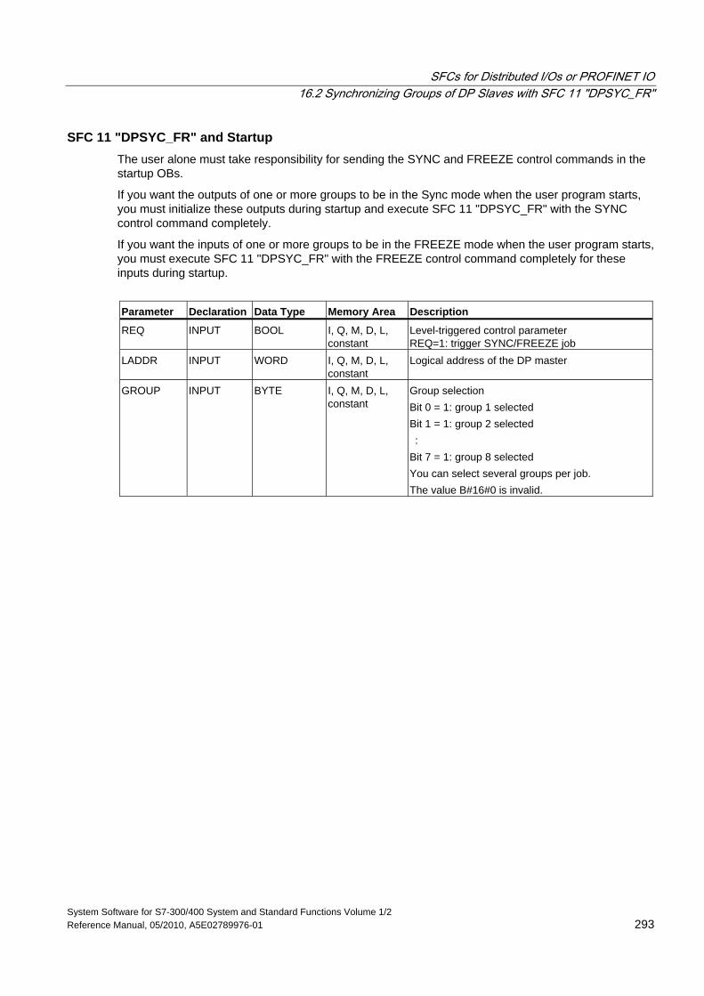
SFCs for Distributed I/Os or PROFINET IO 16.2 Synchronizing Groups of DP Slaves with SFC 11 "DPSYC_FR"
System Software for S7-300/400 System and Standard Functions Volume 1/2 Reference Manual, 05/2010, A5E02789976-01 293
SFC 11 "DPSYC_FR" and Startup The user alone must take responsibility for sending the SYNC and FREEZE control commands in the startup OBs.
If you want the outputs of one or more groups to be in the Sync mode when the user program starts, you must initialize these outputs during startup and execute SFC 11 "DPSYC_FR" with the SYNC control command completely.
If you want the inputs of one or more groups to be in the FREEZE mode when the user program starts, you must execute SFC 11 "DPSYC_FR" with the FREEZE control command completely for these inputs during startup.
Parameter Declaration Data Type Memory Area Description
REQ INPUT BOOL I, Q, M, D, L, constant
Level-triggered control parameter REQ=1: trigger SYNC/FREEZE job
LADDR INPUT WORD I, Q, M, D, L, constant
Logical address of the DP master
GROUP INPUT BYTE I, Q, M, D, L, constant
Group selection Bit 0 = 1: group 1 selected Bit 1 = 1: group 2 selected : Bit 7 = 1: group 8 selected You can select several groups per job. The value B#16#0 is invalid.
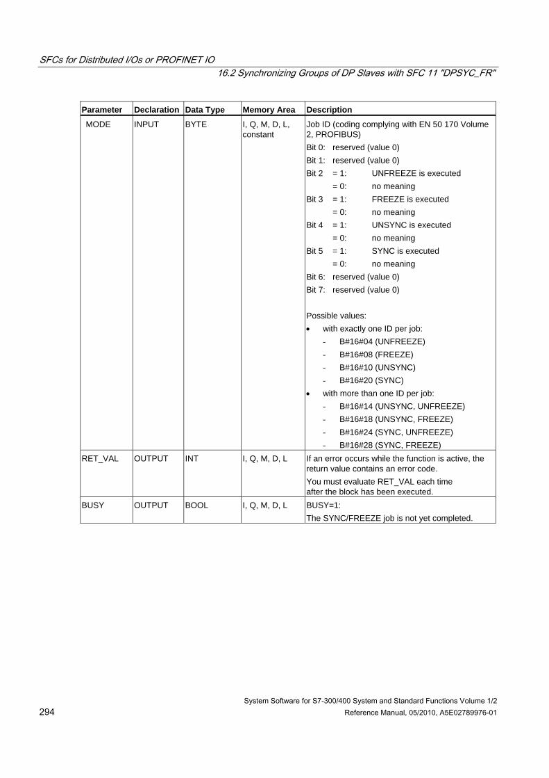
SFCs for Distributed I/Os or PROFINET IO 16.2 Synchronizing Groups of DP Slaves with SFC 11 "DPSYC_FR"
System Software for S7-300/400 System and Standard Functions Volume 1/2 294 Reference Manual, 05/2010, A5E02789976-01
Parameter Declaration Data Type Memory Area Description
MODE INPUT BYTE I, Q, M, D, L, constant
Job ID (coding complying with EN 50 170 Volume 2, PROFIBUS) Bit 0: reserved (value 0) Bit 1: reserved (value 0) Bit 2 = 1: UNFREEZE is executed = 0: no meaning Bit 3 = 1: FREEZE is executed = 0: no meaning Bit 4 = 1: UNSYNC is executed = 0: no meaning Bit 5 = 1: SYNC is executed = 0: no meaning Bit 6: reserved (value 0) Bit 7: reserved (value 0) Possible values: • with exactly one ID per job:
- B#16#04 (UNFREEZE) - B#16#08 (FREEZE) - B#16#10 (UNSYNC) - B#16#20 (SYNC)
• with more than one ID per job: - B#16#14 (UNSYNC, UNFREEZE) - B#16#18 (UNSYNC, FREEZE) - B#16#24 (SYNC, UNFREEZE) - B#16#28 (SYNC, FREEZE)
RET_VAL OUTPUT INT I, Q, M, D, L If an error occurs while the function is active, the return value contains an error code. You must evaluate RET_VAL each time after the block has been executed.
BUSY OUTPUT BOOL I, Q, M, D, L BUSY=1: The SYNC/FREEZE job is not yet completed.
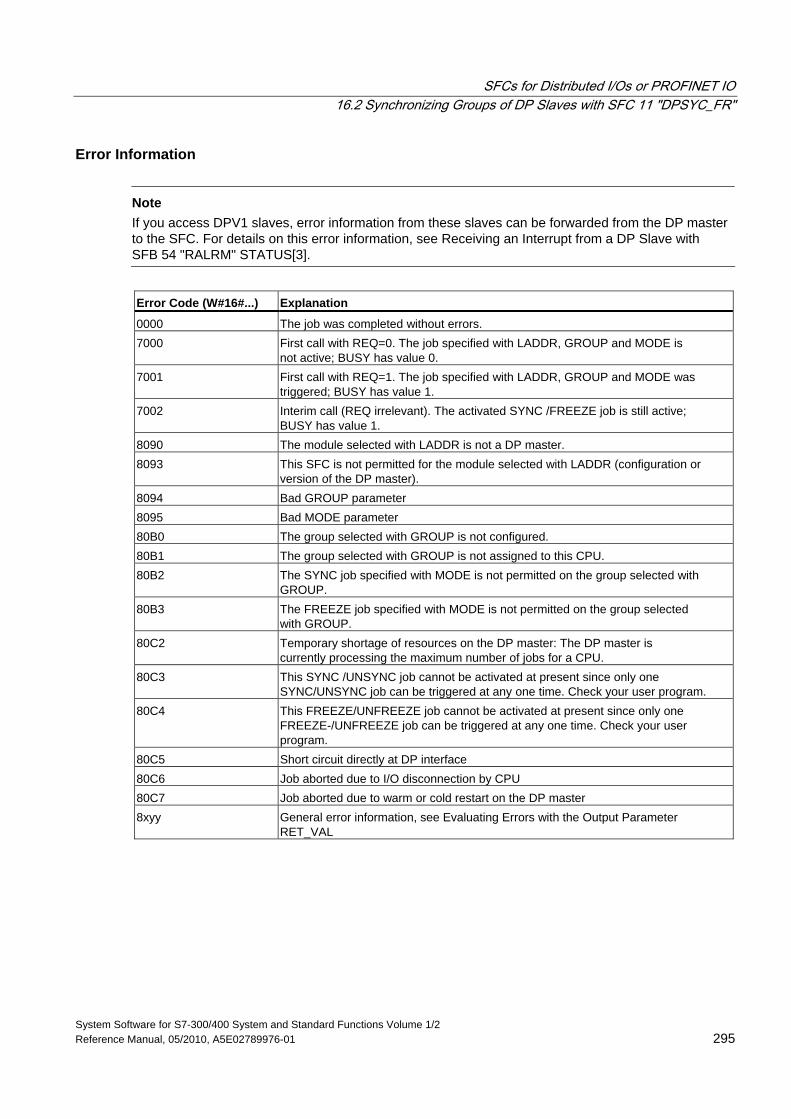
SFCs for Distributed I/Os or PROFINET IO 16.2 Synchronizing Groups of DP Slaves with SFC 11 "DPSYC_FR"
System Software for S7-300/400 System and Standard Functions Volume 1/2 Reference Manual, 05/2010, A5E02789976-01 295
Error Information
Note If you access DPV1 slaves, error information from these slaves can be forwarded from the DP master to the SFC. For details on this error information, see Receiving an Interrupt from a DP Slave with SFB 54 "RALRM" STATUS[3].
Error Code (W#16#...) Explanation
0000 The job was completed without errors. 7000 First call with REQ=0. The job specified with LADDR, GROUP and MODE is
not active; BUSY has value 0. 7001 First call with REQ=1. The job specified with LADDR, GROUP and MODE was
triggered; BUSY has value 1. 7002 Interim call (REQ irrelevant). The activated SYNC /FREEZE job is still active;
BUSY has value 1. 8090 The module selected with LADDR is not a DP master. 8093 This SFC is not permitted for the module selected with LADDR (configuration or
version of the DP master). 8094 Bad GROUP parameter 8095 Bad MODE parameter 80B0 The group selected with GROUP is not configured. 80B1 The group selected with GROUP is not assigned to this CPU. 80B2 The SYNC job specified with MODE is not permitted on the group selected with
GROUP. 80B3 The FREEZE job specified with MODE is not permitted on the group selected
with GROUP. 80C2 Temporary shortage of resources on the DP master: The DP master is
currently processing the maximum number of jobs for a CPU. 80C3 This SYNC /UNSYNC job cannot be activated at present since only one
SYNC/UNSYNC job can be triggered at any one time. Check your user program. 80C4 This FREEZE/UNFREEZE job cannot be activated at present since only one
FREEZE-/UNFREEZE job can be triggered at any one time. Check your user program.
80C5 Short circuit directly at DP interface 80C6 Job aborted due to I/O disconnection by CPU 80C7 Job aborted due to warm or cold restart on the DP master 8xyy General error information, see Evaluating Errors with the Output Parameter
RET_VAL
SFCs for Distributed I/Os or PROFINET IO 16.3 Deactivating and Activating DP Slaves/PROFINET IO Devices with SFC 12 "D_ACT_DP"
System Software for S7-300/400 System and Standard Functions Volume 1/2 296 Reference Manual, 05/2010, A5E02789976-01
16.3 Deactivating and Activating DP Slaves/PROFINET IO Devices with SFC 12 "D_ACT_DP"
Description With SFC 12 "D_ACT_DP, you can specifically deactivate and reactivate configured DP slaves/PROFINET IO devices. In addition, you can determine whether each assigned DP slave or PROFINET IO device is currently activated or deactivated.
If you use SFC 12 to deactivate an IE/PB Link PN IO type of gateway, then all connected PROFIBUS DP slaves will also cease to function. These failures will be reported.
SFC 12 cannot be used on PROFIBUS PA field devices which are connected by a DP/PA link to a DP master system.
Note
As long as one or more SFC 12 job is busy you cannot download a modified configuration from your PG to the CPU (during a CiR process). The CPU rejects initiation of an SFC 12 request when it receives the download of a modified configuration during a CiR process.
Several runs through the cycle control point are required to perform the disabling or enabling job. Therefore, you cannot wait for the end of such a job in a programmed loop.
Purpose If you configure DP slaves/PROFINET IO devices in a CPU which are not actually present or not currently required, the CPU will nevertheless continue to access these DP slaves/PROFINET IO devices at regular intervals. After the slaves are deactivated, further CPU accessing will stop. With PROFIBUS DP, the fastest possible DP bus cycle can be achieved in this manner and the corresponding error events no longer occur.
Application Examples From a machine builder’s point of view, there are numerous device options possible in series production of machines. However, each delivered machine includes only one combination of selected options. Every one of these possible machine options is configured as a DP slave/PROFINET IO devices by the manufacturer in order to create and maintain a common user program having all possible options. With SFC 12, you can deactivate all DP slaves/PROFINET IO devices which are not present at machine startup.
A similar situation exists for machine tools having numerous tooling options available but actually using only a few of them at any given time. These tools are implemented as DP slaves/PROFINET IO devices. With SFC 12, the user program activates the tools currently needed and deactivates those required later.
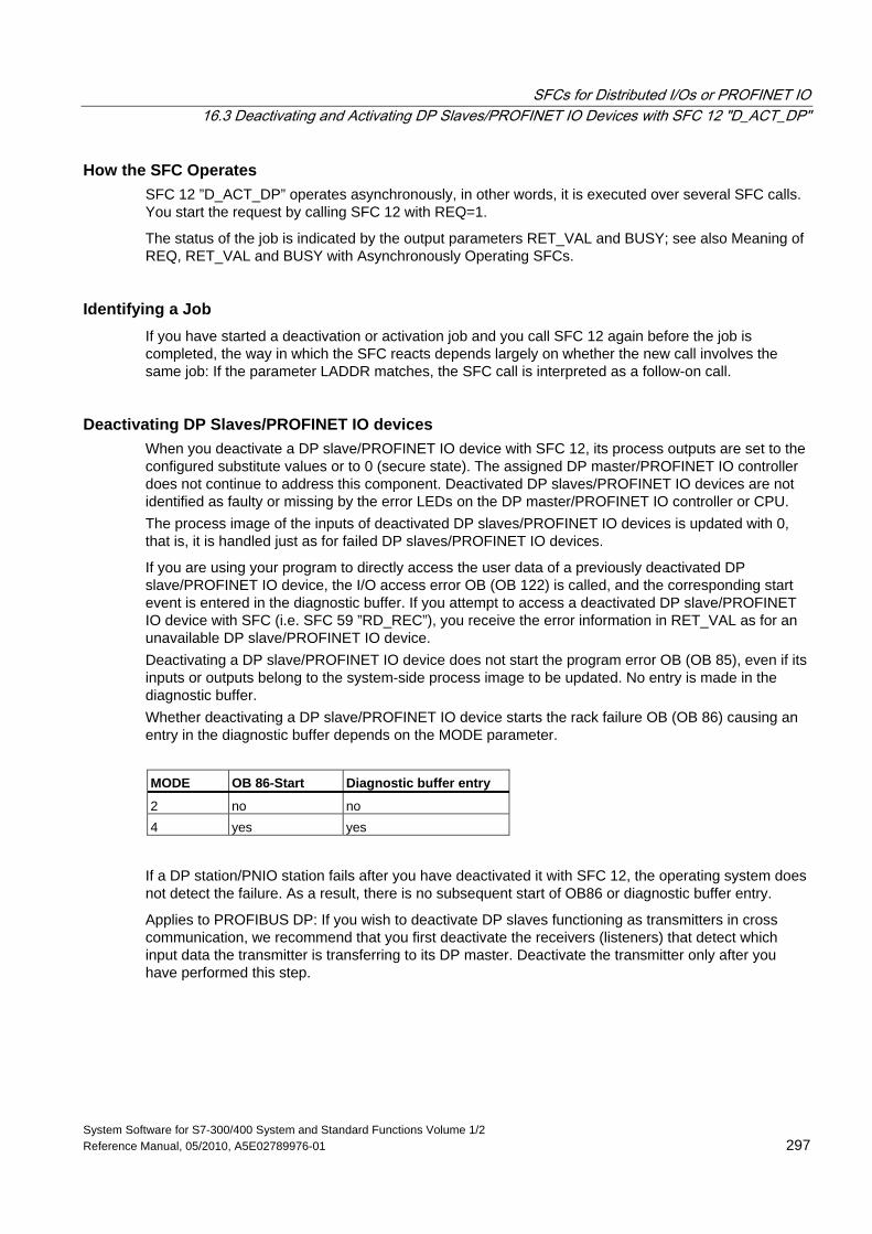
SFCs for Distributed I/Os or PROFINET IO 16.3 Deactivating and Activating DP Slaves/PROFINET IO Devices with SFC 12 "D_ACT_DP"
System Software for S7-300/400 System and Standard Functions Volume 1/2 Reference Manual, 05/2010, A5E02789976-01 297
How the SFC Operates SFC 12 ”D_ACT_DP” operates asynchronously, in other words, it is executed over several SFC calls. You start the request by calling SFC 12 with REQ=1.
The status of the job is indicated by the output parameters RET_VAL and BUSY; see also Meaning of REQ, RET_VAL and BUSY with Asynchronously Operating SFCs.
Identifying a Job If you have started a deactivation or activation job and you call SFC 12 again before the job is completed, the way in which the SFC reacts depends largely on whether the new call involves the same job: If the parameter LADDR matches, the SFC call is interpreted as a follow-on call.
Deactivating DP Slaves/PROFINET IO devices When you deactivate a DP slave/PROFINET IO device with SFC 12, its process outputs are set to the configured substitute values or to 0 (secure state). The assigned DP master/PROFINET IO controller does not continue to address this component. Deactivated DP slaves/PROFINET IO devices are not identified as faulty or missing by the error LEDs on the DP master/PROFINET IO controller or CPU. The process image of the inputs of deactivated DP slaves/PROFINET IO devices is updated with 0, that is, it is handled just as for failed DP slaves/PROFINET IO devices.
If you are using your program to directly access the user data of a previously deactivated DP slave/PROFINET IO device, the I/O access error OB (OB 122) is called, and the corresponding start event is entered in the diagnostic buffer. If you attempt to access a deactivated DP slave/PROFINET IO device with SFC (i.e. SFC 59 ”RD_REC”), you receive the error information in RET_VAL as for an unavailable DP slave/PROFINET IO device. Deactivating a DP slave/PROFINET IO device does not start the program error OB (OB 85), even if its inputs or outputs belong to the system-side process image to be updated. No entry is made in the diagnostic buffer. Whether deactivating a DP slave/PROFINET IO device starts the rack failure OB (OB 86) causing an entry in the diagnostic buffer depends on the MODE parameter.
MODE OB 86-Start Diagnostic buffer entry
2 no no 4 yes yes
If a DP station/PNIO station fails after you have deactivated it with SFC 12, the operating system does not detect the failure. As a result, there is no subsequent start of OB86 or diagnostic buffer entry.
Applies to PROFIBUS DP: If you wish to deactivate DP slaves functioning as transmitters in cross communication, we recommend that you first deactivate the receivers (listeners) that detect which input data the transmitter is transferring to its DP master. Deactivate the transmitter only after you have performed this step.
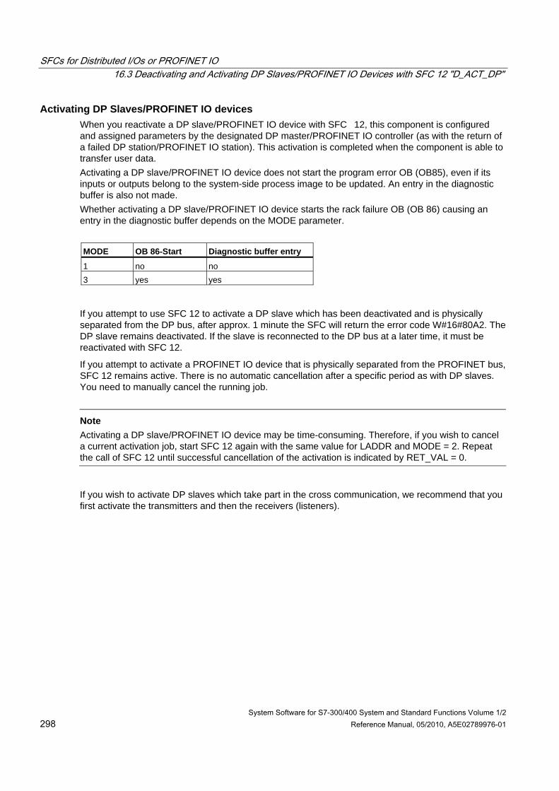
SFCs for Distributed I/Os or PROFINET IO 16.3 Deactivating and Activating DP Slaves/PROFINET IO Devices with SFC 12 "D_ACT_DP"
System Software for S7-300/400 System and Standard Functions Volume 1/2 298 Reference Manual, 05/2010, A5E02789976-01
Activating DP Slaves/PROFINET IO devices When you reactivate a DP slave/PROFINET IO device with SFC 12, this component is configured and assigned parameters by the designated DP master/PROFINET IO controller (as with the return of a failed DP station/PROFINET IO station). This activation is completed when the component is able to transfer user data. Activating a DP slave/PROFINET IO device does not start the program error OB (OB85), even if its inputs or outputs belong to the system-side process image to be updated. An entry in the diagnostic buffer is also not made. Whether activating a DP slave/PROFINET IO device starts the rack failure OB (OB 86) causing an entry in the diagnostic buffer depends on the MODE parameter.
MODE OB 86-Start Diagnostic buffer entry
1 no no 3 yes yes
If you attempt to use SFC 12 to activate a DP slave which has been deactivated and is physically separated from the DP bus, after approx. 1 minute the SFC will return the error code W#16#80A2. The DP slave remains deactivated. If the slave is reconnected to the DP bus at a later time, it must be reactivated with SFC 12.
If you attempt to activate a PROFINET IO device that is physically separated from the PROFINET bus, SFC 12 remains active. There is no automatic cancellation after a specific period as with DP slaves. You need to manually cancel the running job.
Note
Activating a DP slave/PROFINET IO device may be time-consuming. Therefore, if you wish to cancel a current activation job, start SFC 12 again with the same value for LADDR and MODE = 2. Repeat the call of SFC 12 until successful cancellation of the activation is indicated by RET_VAL = 0.
If you wish to activate DP slaves which take part in the cross communication, we recommend that you first activate the transmitters and then the receivers (listeners).
SFCs for Distributed I/Os or PROFINET IO 16.3 Deactivating and Activating DP Slaves/PROFINET IO Devices with SFC 12 "D_ACT_DP"
System Software for S7-300/400 System and Standard Functions Volume 1/2 Reference Manual, 05/2010, A5E02789976-01 299
CPU Startup Depending on the startup mode, the CPU operating system behaves as follows regarding DP slaves/PROFINET IO devices:
• In the startup modes cold and warm restart, slaves/devices are activated automatically.
- With S7-400: Activation of the DP slaves/PROFINET IO devices may take some time. In this case, the CPU continues to run and I/O access errors occur until the activation is completed. The reaction of the CPU depends on the configuration (OB 85 call for I/O access errors) and the program in OB 85. You cannot suppress these I/O access errors.
- With S7-300: Activation of the DP slaves/PROFINET IO devices may take some time. In this case, the CPU waits until the DP slaves / PROFINET IO devices are activated. The maximum waiting period for activation of the DP slaves / PROFINET IO devices is approx. 1 minute. No I/O access errors occur during this time.
• In the hot restart mode, the slaves/devices activation status remains unchanged, that is, activated slaves/devices remain activated and deactivated slaves/devices remain deactivated.
After the CPU start-up, the CPU cyclically attempts to contact all configured and not deactivated slaves/devices that are either not present or not responding.
Note The startup OBs do not support the call of SFC 12.
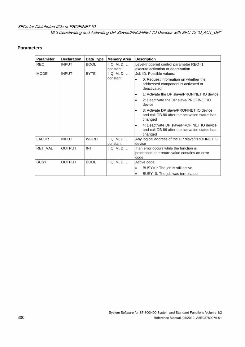
SFCs for Distributed I/Os or PROFINET IO 16.3 Deactivating and Activating DP Slaves/PROFINET IO Devices with SFC 12 "D_ACT_DP"
System Software for S7-300/400 System and Standard Functions Volume 1/2 300 Reference Manual, 05/2010, A5E02789976-01
Parameters Parameter Declaration Data Type Memory Area Description REQ INPUT BOOL I, Q, M, D, L,
constant. Level-triggered control parameter REQ=1: execute activation or deactivation
MODE INPUT BYTE I, Q, M, D, L, constant
Job ID. Possible values: • 0: Request information on whether the
addressed component is activated or deactivated
• 1: Activate the DP slave/PROFINET IO device • 2: Deactivate the DP slave/PROFINET IO
device • 3: Activate DP slave/PROFINET IO device
and call OB 86 after the activation status has changed
• 4: Deactivate DP slave/PROFINET IO device and call OB 86 after the activation status has changed
LADDR INPUT WORD I, Q, M, D, L, constant
Any logical address of the DP slave/PROFINET IO device
RET_VAL OUTPUT INT I, Q, M, D, L If an error occurs while the function is processed, the return value contains an error code.
BUSY OUTPUT BOOL I, Q, M, D, L Active code: • BUSY=1: The job is still active. • BUSY=0: The job was terminated.
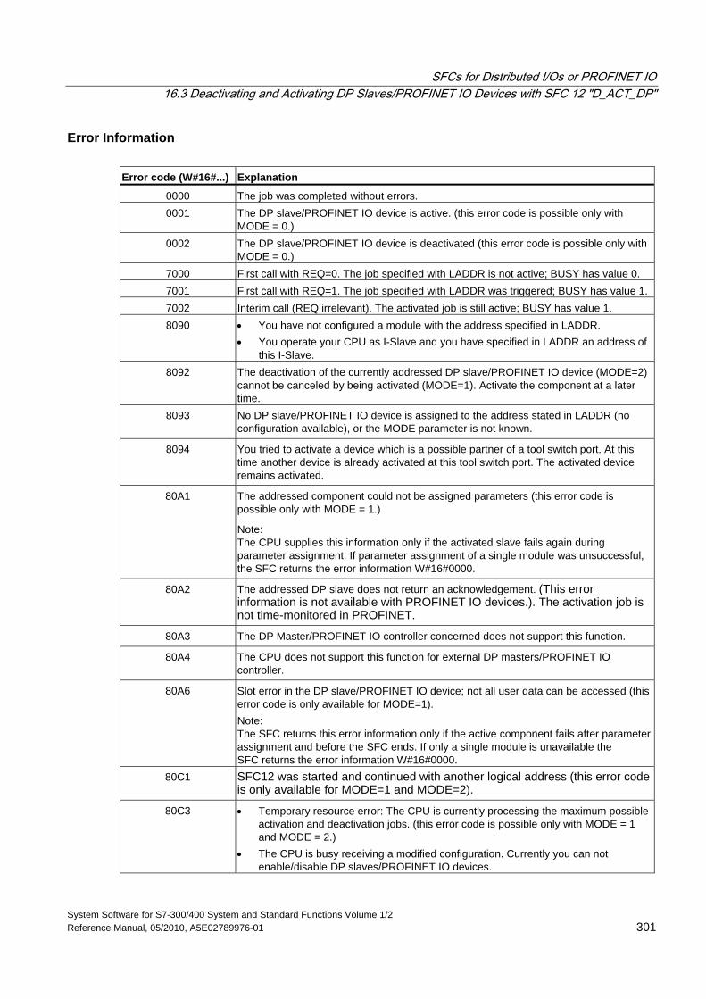
SFCs for Distributed I/Os or PROFINET IO 16.3 Deactivating and Activating DP Slaves/PROFINET IO Devices with SFC 12 "D_ACT_DP"
System Software for S7-300/400 System and Standard Functions Volume 1/2 Reference Manual, 05/2010, A5E02789976-01 301
Error Information Error code (W#16#...) Explanation
0000 The job was completed without errors. 0001 The DP slave/PROFINET IO device is active. (this error code is possible only with
MODE = 0.) 0002 The DP slave/PROFINET IO device is deactivated (this error code is possible only with
MODE = 0.) 7000 First call with REQ=0. The job specified with LADDR is not active; BUSY has value 0. 7001 First call with REQ=1. The job specified with LADDR was triggered; BUSY has value 1. 7002 Interim call (REQ irrelevant). The activated job is still active; BUSY has value 1. 8090 • You have not configured a module with the address specified in LADDR.
• You operate your CPU as I-Slave and you have specified in LADDR an address of this I-Slave.
8092 The deactivation of the currently addressed DP slave/PROFINET IO device (MODE=2) cannot be canceled by being activated (MODE=1). Activate the component at a later time.
8093 No DP slave/PROFINET IO device is assigned to the address stated in LADDR (no configuration available), or the MODE parameter is not known.
8094 You tried to activate a device which is a possible partner of a tool switch port. At this time another device is already activated at this tool switch port. The activated device remains activated.
80A1 The addressed component could not be assigned parameters (this error code is possible only with MODE = 1.)
Note: The CPU supplies this information only if the activated slave fails again during parameter assignment. If parameter assignment of a single module was unsuccessful, the SFC returns the error information W#16#0000.
80A2 The addressed DP slave does not return an acknowledgement. (This error information is not available with PROFINET IO devices.). The activation job is not time-monitored in PROFINET.
80A3 The DP Master/PROFINET IO controller concerned does not support this function.
80A4 The CPU does not support this function for external DP masters/PROFINET IO controller.
80A6 Slot error in the DP slave/PROFINET IO device; not all user data can be accessed (this error code is only available for MODE=1). Note: The SFC returns this error information only if the active component fails after parameter assignment and before the SFC ends. If only a single module is unavailable the SFC returns the error information W#16#0000.
80C1 SFC12 was started and continued with another logical address (this error code is only available for MODE=1 and MODE=2).
80C3 • Temporary resource error: The CPU is currently processing the maximum possible activation and deactivation jobs. (this error code is possible only with MODE = 1 and MODE = 2.)
• The CPU is busy receiving a modified configuration. Currently you can not enable/disable DP slaves/PROFINET IO devices.
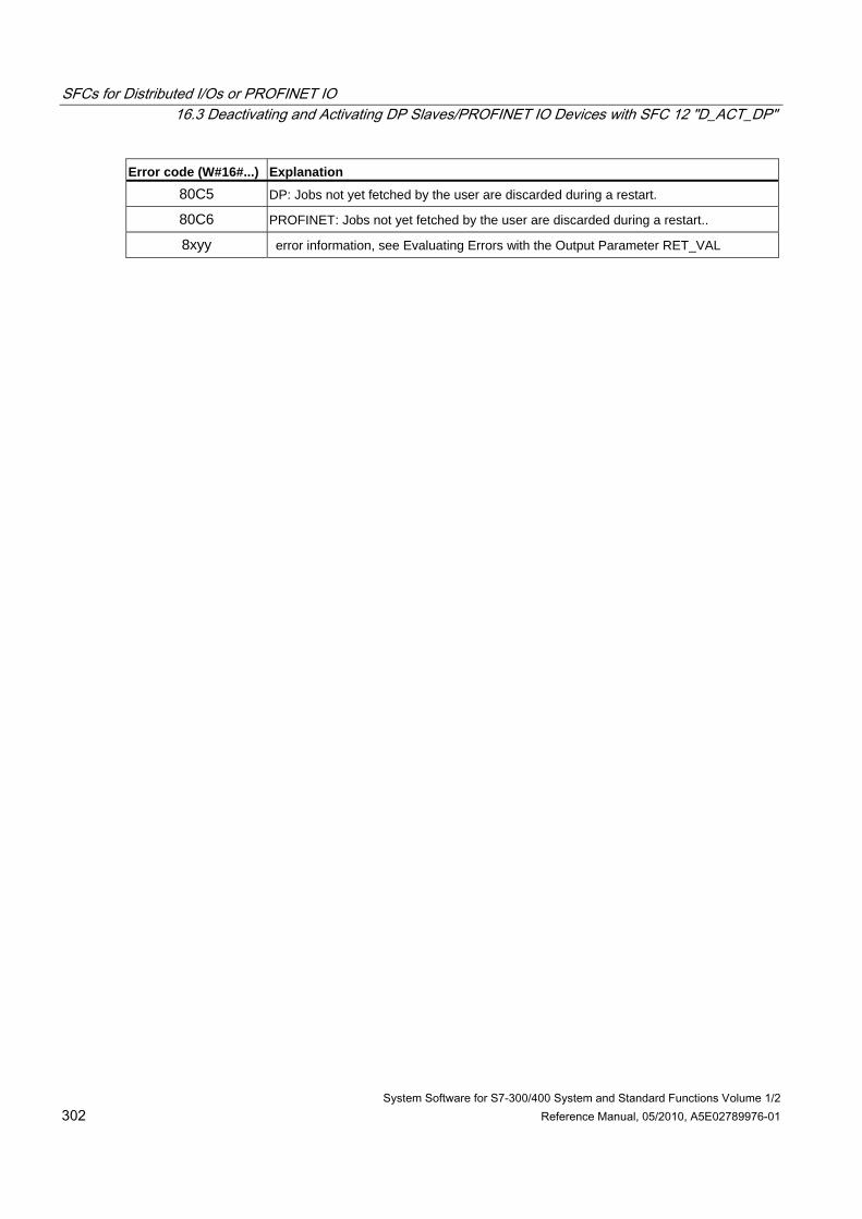
SFCs for Distributed I/Os or PROFINET IO 16.3 Deactivating and Activating DP Slaves/PROFINET IO Devices with SFC 12 "D_ACT_DP"
System Software for S7-300/400 System and Standard Functions Volume 1/2 302 Reference Manual, 05/2010, A5E02789976-01
Error code (W#16#...) Explanation 80C5 DP: Jobs not yet fetched by the user are discarded during a restart.
80C6 PROFINET: Jobs not yet fetched by the user are discarded during a restart..
8xyy error information, see Evaluating Errors with the Output Parameter RET_VAL
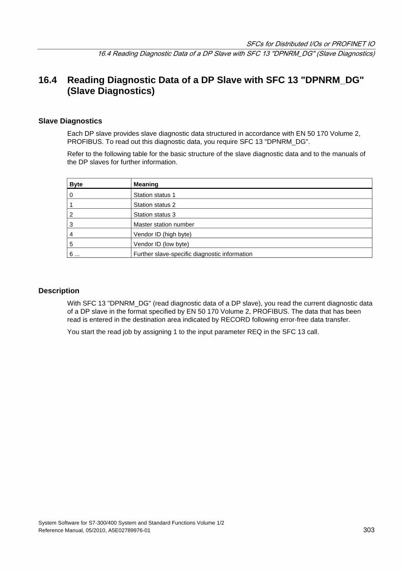
SFCs for Distributed I/Os or PROFINET IO 16.4 Reading Diagnostic Data of a DP Slave with SFC 13 "DPNRM_DG" (Slave Diagnostics)
System Software for S7-300/400 System and Standard Functions Volume 1/2 Reference Manual, 05/2010, A5E02789976-01 303
16.4 Reading Diagnostic Data of a DP Slave with SFC 13 "DPNRM_DG" (Slave Diagnostics)
Slave Diagnostics Each DP slave provides slave diagnostic data structured in accordance with EN 50 170 Volume 2, PROFIBUS. To read out this diagnostic data, you require SFC 13 "DPNRM_DG".
Refer to the following table for the basic structure of the slave diagnostic data and to the manuals of the DP slaves for further information.
Byte Meaning
0 Station status 1 1 Station status 2 2 Station status 3 3 Master station number 4 Vendor ID (high byte) 5 Vendor ID (low byte) 6 ... Further slave-specific diagnostic information
Description With SFC 13 "DPNRM_DG" (read diagnostic data of a DP slave), you read the current diagnostic data of a DP slave in the format specified by EN 50 170 Volume 2, PROFIBUS. The data that has been read is entered in the destination area indicated by RECORD following error-free data transfer.
You start the read job by assigning 1 to the input parameter REQ in the SFC 13 call.
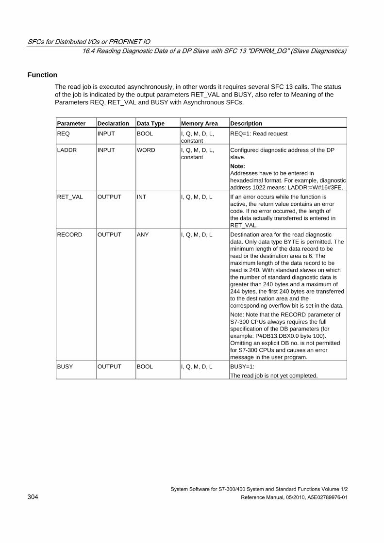
SFCs for Distributed I/Os or PROFINET IO 16.4 Reading Diagnostic Data of a DP Slave with SFC 13 "DPNRM_DG" (Slave Diagnostics)
System Software for S7-300/400 System and Standard Functions Volume 1/2 304 Reference Manual, 05/2010, A5E02789976-01
Function The read job is executed asynchronously, in other words it requires several SFC 13 calls. The status of the job is indicated by the output parameters RET_VAL and BUSY, also refer to Meaning of the Parameters REQ, RET_VAL and BUSY with Asynchronous SFCs.
Parameter Declaration Data Type Memory Area Description
REQ INPUT BOOL I, Q, M, D, L, constant
REQ=1: Read request
LADDR INPUT WORD I, Q, M, D, L, constant
Configured diagnostic address of the DP slave. Note: Addresses have to be entered in hexadecimal format. For example, diagnostic address 1022 means: LADDR:=W#16#3FE.
RET_VAL OUTPUT INT I, Q, M, D, L If an error occurs while the function is active, the return value contains an error code. If no error occurred, the length of the data actually transferred is entered in RET_VAL.
RECORD OUTPUT ANY I, Q, M, D, L Destination area for the read diagnostic data. Only data type BYTE is permitted. The minimum length of the data record to be read or the destination area is 6. The maximum length of the data record to be read is 240. With standard slaves on which the number of standard diagnostic data is greater than 240 bytes and a maximum of 244 bytes, the first 240 bytes are transferred to the destination area and the corresponding overflow bit is set in the data.Note: Note that the RECORD parameter of S7-300 CPUs always requires the full specification of the DB parameters (for example: P#DB13.DBX0.0 byte 100). Omitting an explicit DB no. is not permitted for S7-300 CPUs and causes an error message in the user program.
BUSY OUTPUT BOOL I, Q, M, D, L BUSY=1: The read job is not yet completed.
SFCs for Distributed I/Os or PROFINET IO 16.4 Reading Diagnostic Data of a DP Slave with SFC 13 "DPNRM_DG" (Slave Diagnostics)
System Software for S7-300/400 System and Standard Functions Volume 1/2 Reference Manual, 05/2010, A5E02789976-01 305
Input Parameter RECORD The CPU evaluates the actual length of the diagnostic data that were read as following:
• If the length specified for RECORD is less than the number of data bytes supplied, the data are discarded and a corresponding error code is entered in RET_VAL.
• If the length specified for RECORD is greater than or equal to the number of supplied data bytes, the data are accepted in the destination area and the actual length is entered in RET_VAL as a positive value.
Note
You must make sure that the actual parameters of RECORD match in all calls belonging to a job. A job is uniquely identified by the LADDR input parameter.
Standard Slaves with more than 240 Bytes of Diagnostic Data With standard slaves on which the number of standard diagnostic data is between 241 and 244 bytes, note the following points:
• If the length specified for RECORD is less than 240 bytes, the data are discarded and the corresponding error information is entered in RET_VAL.
• If the length specified for RECORD is greater than or equal to 240 bytes, the first 240 bytes of the standard diagnostic data are transferred to the destination area and the overflow bit is set in the data.
Output Parameter RET_VAL • If an error occurs while the function is being executed, the return value contains an error code.
• If no error occurs during the data transfer, RET_VAL contains the length of the data read in bytes as a positive number.
Note
The amount of data read in a DP slave depends on its diagnostic status.
SFCs for Distributed I/Os or PROFINET IO 16.4 Reading Diagnostic Data of a DP Slave with SFC 13 "DPNRM_DG" (Slave Diagnostics)
System Software for S7-300/400 System and Standard Functions Volume 1/2 306 Reference Manual, 05/2010, A5E02789976-01
Error Information How to evaluate the error information of the RET_VAL parameter is explained in Evaluating Errors with the Output Parameter RET_VAL. This chapter also contains the general error information for the SFCs. The error information specific to SFC 13 is a subset of the error information for SFC 59 "RD_REC," see Reading a Data Record with SFC 59 "RD_REC"
System Resources for S7-400 When SFC 13 "DPNRM_DG" is called for a job that is not currently being processed, resources of the CPU (memory space) are occupied on the S7-400. You can call SFC 13 in quick succession for several DP slaves providing that you do not exceed the maximum number of "simultaneously" active SFC 13 jobs for your CPU. You will find the maximum number of such jobs in /101/.
If you activate several jobs "simultaneously," all the jobs will be executed without interfering with each other.
If you reach the limits of the system resources, this is indicated in RET_VAL. In this case, repeat the job.
SFCs for Distributed I/Os or PROFINET IO 16.5 Reading Consistent Data of a DP Standard Slave//PROFINET IO Device with SFC 14 "DPRD_DAT"
System Software for S7-300/400 System and Standard Functions Volume 1/2 Reference Manual, 05/2010, A5E02789976-01 307
16.5 Reading Consistent Data of a DP Standard Slave//PROFINET IO Device with SFC 14 "DPRD_DAT"
Data Consistency Refer to the section Overview of S7 Communication and S7 Basic Communication - Data consistency.
Purpose of SFC 14 You require SFC 14 "DPRD_DAT" because you can only read out a maximum of four continuous bytes using load instructions that access the I/Os or the process image input table.
Note
If required, you can also read consistent data via the process image of the inputs. To determine whether the CPU supports this functionality, refer to the "Automation System S7-300, Hardware and Installation" manual.
All S7-400 CPUs support this functionality.
! Caution When using SFC 14 "DPRD_DAT", avoid accessing I/O areas that have process image partitions with OB6x connections (clocked interrupts) assigned to them.
Description With SFC 14 "DPRD_DAT" (read consistent data of a DP standard slave), you read the consistent data of a DP standard slave/PROFINET IO device.
To find the maximum length that applies for S7-300 CPUs, refer to the manuals, Automation System S7-300, Hardware and Installation, ET 200S Interface Submodule, IM151-7 CPU, or Base Submodule BM147CPU. For S7-400 CPUs refer to the manual Automation System S7-400 CPU Data. If no error occurred during the data transfer, the data that have been read are entered in the destination area identified by RECORD.
The destination area must have the same length as configured for the selected module with STEP 7.
If you read from a DP standard slave with a modular design or with several DP identifiers, you can only access the data of one module/DP identifier per SFC 14 call specifying the configured start address.
Note An access with SFC 14 "DPRD_DAT" can only be to data areas that are three or more than four bytes long. Otherwise the access is rejected with the error code W#16#8090.
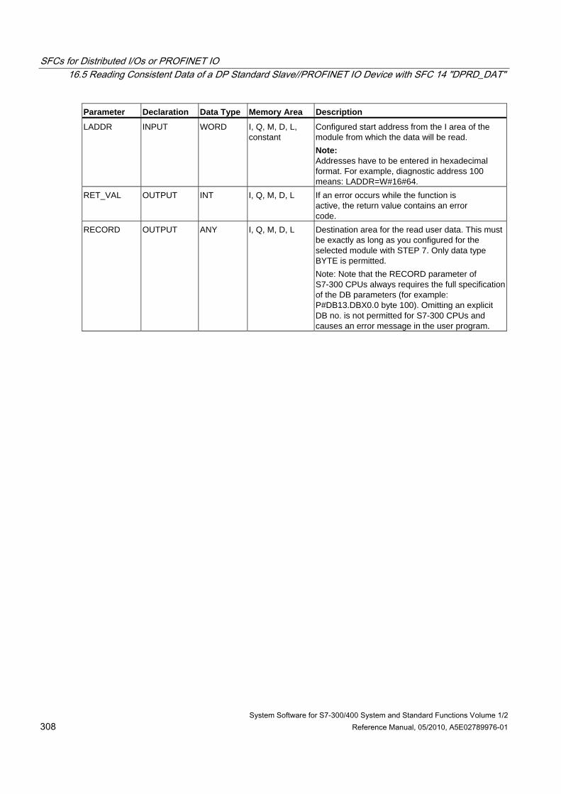
SFCs for Distributed I/Os or PROFINET IO 16.5 Reading Consistent Data of a DP Standard Slave//PROFINET IO Device with SFC 14 "DPRD_DAT"
System Software for S7-300/400 System and Standard Functions Volume 1/2 308 Reference Manual, 05/2010, A5E02789976-01
Parameter Declaration Data Type Memory Area Description
LADDR INPUT WORD I, Q, M, D, L, constant
Configured start address from the I area of the module from which the data will be read. Note: Addresses have to be entered in hexadecimal format. For example, diagnostic address 100 means: LADDR=W#16#64.
RET_VAL OUTPUT INT I, Q, M, D, L If an error occurs while the function is active, the return value contains an error code.
RECORD OUTPUT ANY I, Q, M, D, L Destination area for the read user data. This must be exactly as long as you configured for the selected module with STEP 7. Only data type BYTE is permitted. Note: Note that the RECORD parameter of S7-300 CPUs always requires the full specification of the DB parameters (for example: P#DB13.DBX0.0 byte 100). Omitting an explicit DB no. is not permitted for S7-300 CPUs and causes an error message in the user program.
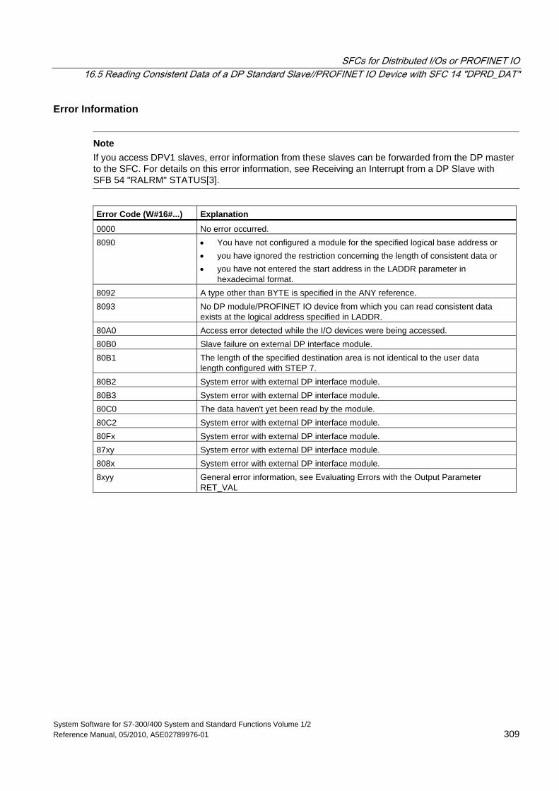
SFCs for Distributed I/Os or PROFINET IO 16.5 Reading Consistent Data of a DP Standard Slave//PROFINET IO Device with SFC 14 "DPRD_DAT"
System Software for S7-300/400 System and Standard Functions Volume 1/2 Reference Manual, 05/2010, A5E02789976-01 309
Error Information
Note If you access DPV1 slaves, error information from these slaves can be forwarded from the DP master to the SFC. For details on this error information, see Receiving an Interrupt from a DP Slave with SFB 54 "RALRM" STATUS[3].
Error Code (W#16#...) Explanation
0000 No error occurred. 8090 • You have not configured a module for the specified logical base address or
• you have ignored the restriction concerning the length of consistent data or • you have not entered the start address in the LADDR parameter in
hexadecimal format. 8092 A type other than BYTE is specified in the ANY reference. 8093 No DP module/PROFINET IO device from which you can read consistent data
exists at the logical address specified in LADDR. 80A0 Access error detected while the I/O devices were being accessed. 80B0 Slave failure on external DP interface module. 80B1 The length of the specified destination area is not identical to the user data
length configured with STEP 7. 80B2 System error with external DP interface module. 80B3 System error with external DP interface module. 80C0 The data haven't yet been read by the module. 80C2 System error with external DP interface module. 80Fx System error with external DP interface module. 87xy System error with external DP interface module. 808x System error with external DP interface module. 8xyy General error information, see Evaluating Errors with the Output Parameter
RET_VAL
SFCs for Distributed I/Os or PROFINET IO 16.6 Writing Consistent Data to a DP Standard Slave/PROFINET IO Device with SFC 15 "DPWR_DAT"
System Software for S7-300/400 System and Standard Functions Volume 1/2 310 Reference Manual, 05/2010, A5E02789976-01
16.6 Writing Consistent Data to a DP Standard Slave/PROFINET IO Device with SFC 15 "DPWR_DAT"
Data Consistency Refer to the section: Overview of S7 Communication and S7 Basic Communication – Data consistency.
Purpose of SFC 15 You require SFC 15 "DPWR_DAT" because you can only write a maximum of four continuous bytes using the transfer instructions that access the I/Os or the process image input table.
Note
If required, you can also read consistent data via the process image of the inputs. To determine whether the CPU supports this functionality, refer to the "Automation System S7-300, Hardware and Installation" manual.
All S7-400 CPUs support this functionality.
When writing consistent data, do not use the two options at the same time: Use either SFC 15 or write via the process output image.
! Caution When using SFC 15 "DPWR_DAT", avoid accessing I/O areas that have process image partitions with OB6x connections (clocked interrupts) assigned to them.
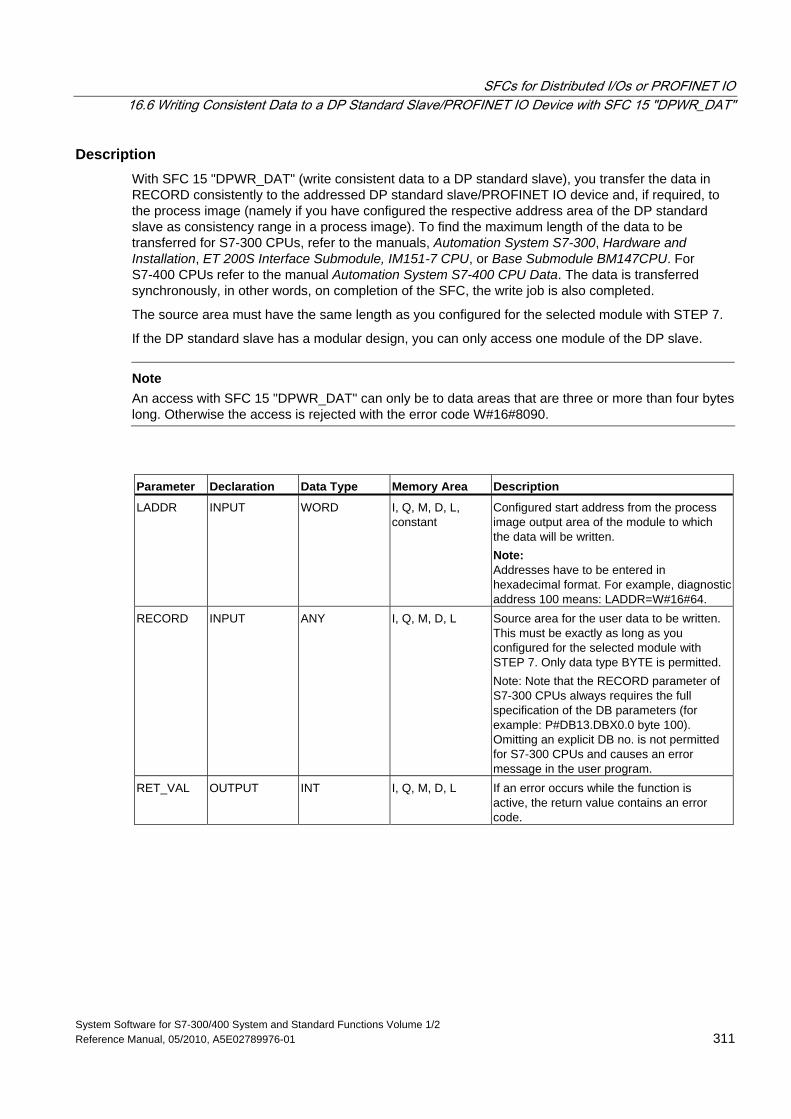
SFCs for Distributed I/Os or PROFINET IO 16.6 Writing Consistent Data to a DP Standard Slave/PROFINET IO Device with SFC 15 "DPWR_DAT"
System Software for S7-300/400 System and Standard Functions Volume 1/2 Reference Manual, 05/2010, A5E02789976-01 311
Description With SFC 15 "DPWR_DAT" (write consistent data to a DP standard slave), you transfer the data in RECORD consistently to the addressed DP standard slave/PROFINET IO device and, if required, to the process image (namely if you have configured the respective address area of the DP standard slave as consistency range in a process image). To find the maximum length of the data to be transferred for S7-300 CPUs, refer to the manuals, Automation System S7-300, Hardware and Installation, ET 200S Interface Submodule, IM151-7 CPU, or Base Submodule BM147CPU. For S7-400 CPUs refer to the manual Automation System S7-400 CPU Data. The data is transferred synchronously, in other words, on completion of the SFC, the write job is also completed.
The source area must have the same length as you configured for the selected module with STEP 7.
If the DP standard slave has a modular design, you can only access one module of the DP slave.
Note An access with SFC 15 "DPWR_DAT" can only be to data areas that are three or more than four bytes long. Otherwise the access is rejected with the error code W#16#8090.
Parameter Declaration Data Type Memory Area Description
LADDR INPUT WORD I, Q, M, D, L, constant
Configured start address from the process image output area of the module to which the data will be written. Note: Addresses have to be entered in hexadecimal format. For example, diagnostic address 100 means: LADDR=W#16#64.
RECORD INPUT ANY I, Q, M, D, L Source area for the user data to be written. This must be exactly as long as you configured for the selected module with STEP 7. Only data type BYTE is permitted. Note: Note that the RECORD parameter of S7-300 CPUs always requires the full specification of the DB parameters (for example: P#DB13.DBX0.0 byte 100). Omitting an explicit DB no. is not permitted for S7-300 CPUs and causes an error message in the user program.
RET_VAL OUTPUT INT I, Q, M, D, L If an error occurs while the function is active, the return value contains an error code.
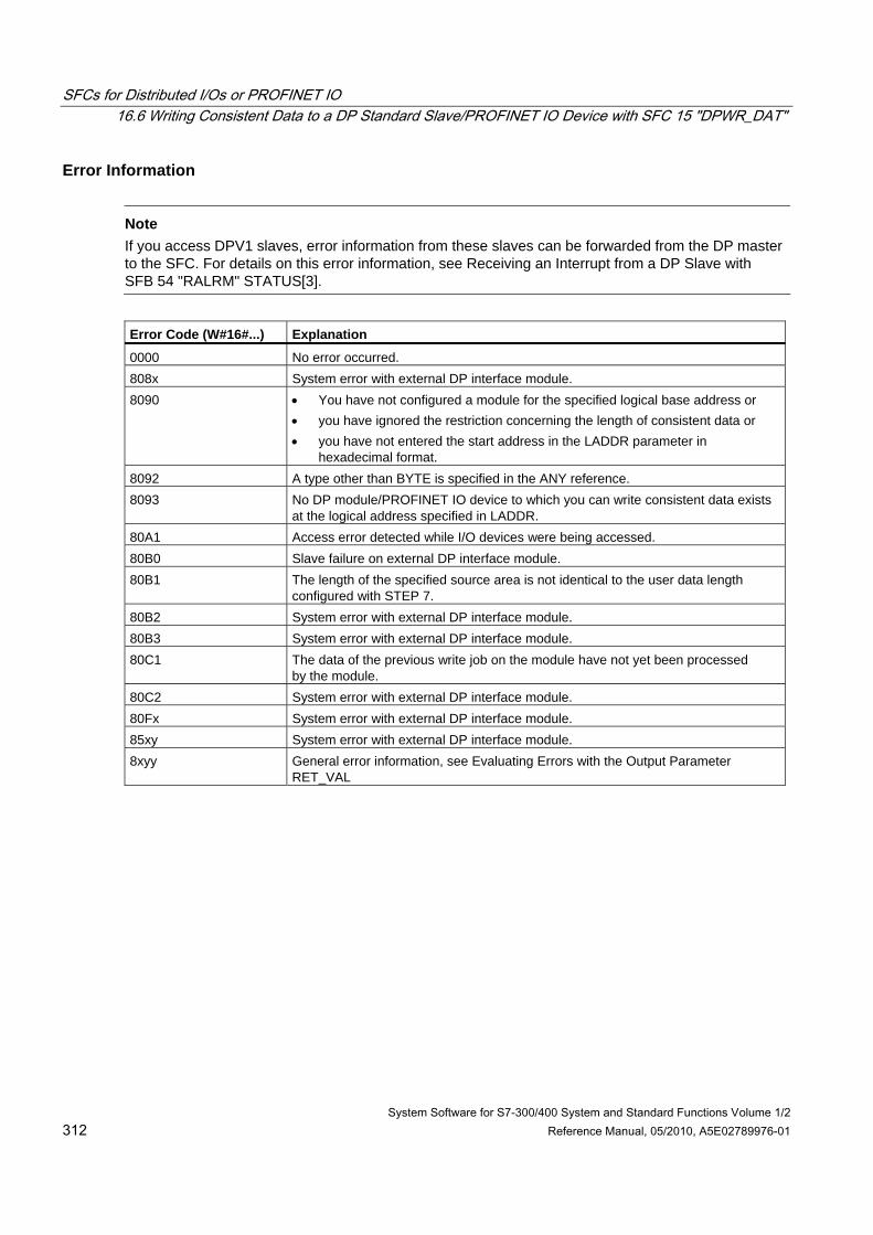
SFCs for Distributed I/Os or PROFINET IO 16.6 Writing Consistent Data to a DP Standard Slave/PROFINET IO Device with SFC 15 "DPWR_DAT"
System Software for S7-300/400 System and Standard Functions Volume 1/2 312 Reference Manual, 05/2010, A5E02789976-01
Error Information
Note If you access DPV1 slaves, error information from these slaves can be forwarded from the DP master to the SFC. For details on this error information, see Receiving an Interrupt from a DP Slave with SFB 54 "RALRM" STATUS[3].
Error Code (W#16#...) Explanation
0000 No error occurred. 808x System error with external DP interface module. 8090 • You have not configured a module for the specified logical base address or
• you have ignored the restriction concerning the length of consistent data or • you have not entered the start address in the LADDR parameter in
hexadecimal format. 8092 A type other than BYTE is specified in the ANY reference. 8093 No DP module/PROFINET IO device to which you can write consistent data exists
at the logical address specified in LADDR. 80A1 Access error detected while I/O devices were being accessed. 80B0 Slave failure on external DP interface module. 80B1 The length of the specified source area is not identical to the user data length
configured with STEP 7. 80B2 System error with external DP interface module. 80B3 System error with external DP interface module. 80C1 The data of the previous write job on the module have not yet been processed
by the module. 80C2 System error with external DP interface module. 80Fx System error with external DP interface module. 85xy System error with external DP interface module. 8xyy General error information, see Evaluating Errors with the Output Parameter
RET_VAL
System Software for S7-300/400 System and Standard Functions Volume 1/2 Reference Manual, 05/2010, A5E02789976-01 313
17 PROFINET
17.1 Background Information on SFCs 112, 113 and 114
Note
As default, the operating system updates both the PROFINET CBA component as well as the DP interconnections at the cycle checkpoint. If, however, you have disabled these automatic updates in the configuration (for example to improve the time response of the CPU), you will have to perform the updates yourself. You can do this by calling SFCs 112 to 114 at suitable times.
These updates can only be disabled as a group and not individually in the configuration.
Shadow Memory The interface DB is the user program interface for the PROFINET CBA component. To ensure that the inputs and output are consistent when the associated program sections are running, each interface DB has an identically structured memory area that is managed by the operating system. This area is called "shadow memory." In your program, you can only access the interface DB, and other (external) PROFINET CBA components can only access the shadow memory. This arrangement prevents conflicts in accessing the inputs and outputs of the interface DB.
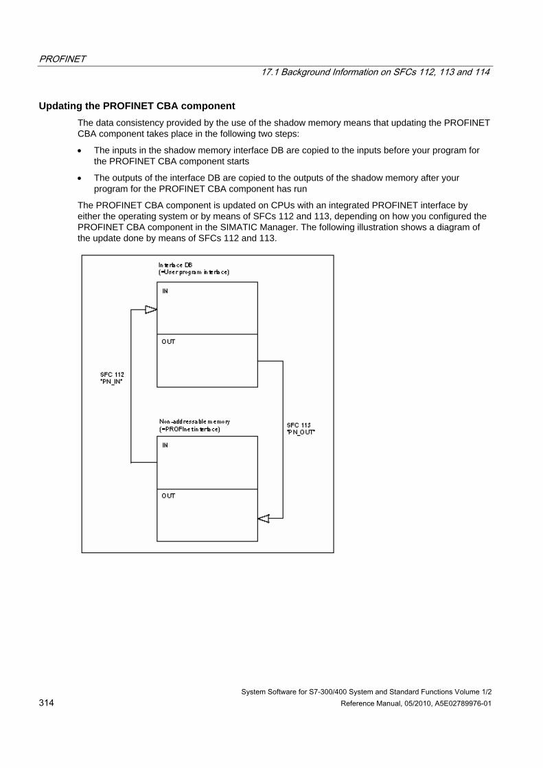
PROFINET 17.1 Background Information on SFCs 112, 113 and 114
System Software for S7-300/400 System and Standard Functions Volume 1/2 314 Reference Manual, 05/2010, A5E02789976-01
Updating the PROFINET CBA component The data consistency provided by the use of the shadow memory means that updating the PROFINET CBA component takes place in the following two steps:
• The inputs in the shadow memory interface DB are copied to the inputs before your program for the PROFINET CBA component starts
• The outputs of the interface DB are copied to the outputs of the shadow memory after your program for the PROFINET CBA component has run
The PROFINET CBA component is updated on CPUs with an integrated PROFINET interface by either the operating system or by means of SFCs 112 and 113, depending on how you configured the PROFINET CBA component in the SIMATIC Manager. The following illustration shows a diagram of the update done by means of SFCs 112 and 113.
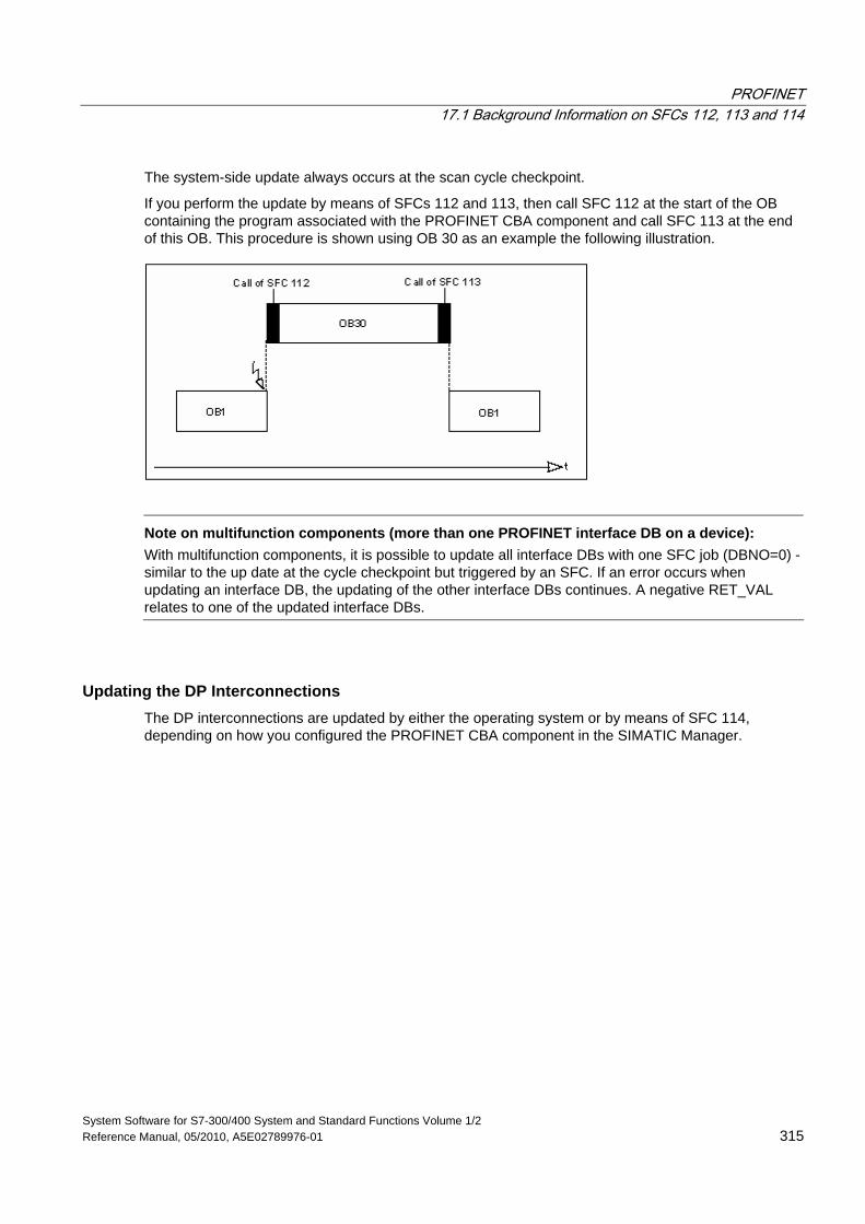
PROFINET 17.1 Background Information on SFCs 112, 113 and 114
System Software for S7-300/400 System and Standard Functions Volume 1/2 Reference Manual, 05/2010, A5E02789976-01 315
The system-side update always occurs at the scan cycle checkpoint.
If you perform the update by means of SFCs 112 and 113, then call SFC 112 at the start of the OB containing the program associated with the PROFINET CBA component and call SFC 113 at the end of this OB. This procedure is shown using OB 30 as an example the following illustration.
Note on multifunction components (more than one PROFINET interface DB on a device):
With multifunction components, it is possible to update all interface DBs with one SFC job (DBNO=0) -similar to the up date at the cycle checkpoint but triggered by an SFC. If an error occurs when updating an interface DB, the updating of the other interface DBs continues. A negative RET_VAL relates to one of the updated interface DBs.
Updating the DP Interconnections The DP interconnections are updated by either the operating system or by means of SFC 114, depending on how you configured the PROFINET CBA component in the SIMATIC Manager.
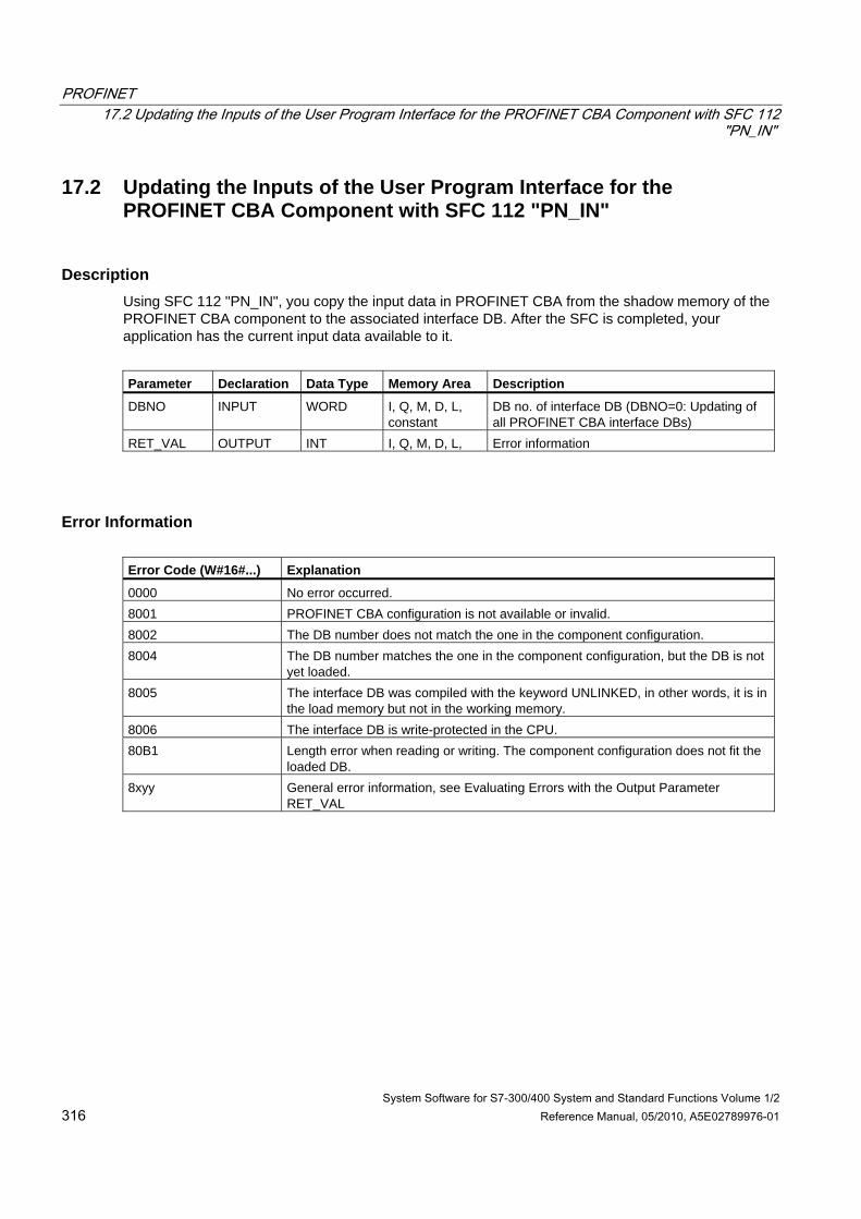
PROFINET 17.2 Updating the Inputs of the User Program Interface for the PROFINET CBA Component with SFC 112
"PN_IN"
System Software for S7-300/400 System and Standard Functions Volume 1/2 316 Reference Manual, 05/2010, A5E02789976-01
17.2 Updating the Inputs of the User Program Interface for the PROFINET CBA Component with SFC 112 "PN_IN"
Description Using SFC 112 "PN_IN", you copy the input data in PROFINET CBA from the shadow memory of the PROFINET CBA component to the associated interface DB. After the SFC is completed, your application has the current input data available to it.
Parameter Declaration Data Type Memory Area Description
DBNO INPUT WORD I, Q, M, D, L, constant
DB no. of interface DB (DBNO=0: Updating of all PROFINET CBA interface DBs)
RET_VAL OUTPUT INT I, Q, M, D, L, Error information
Error Information Error Code (W#16#...) Explanation
0000 No error occurred. 8001 PROFINET CBA configuration is not available or invalid. 8002 The DB number does not match the one in the component configuration. 8004 The DB number matches the one in the component configuration, but the DB is not
yet loaded. 8005 The interface DB was compiled with the keyword UNLINKED, in other words, it is in
the load memory but not in the working memory. 8006 The interface DB is write-protected in the CPU. 80B1 Length error when reading or writing. The component configuration does not fit the
loaded DB. 8xyy General error information, see Evaluating Errors with the Output Parameter
RET_VAL
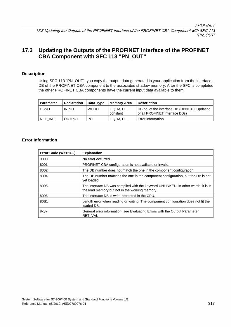
PROFINET 17.3 Updating the Outputs of the PROFINET Interface of the PROFINET CBA Component with SFC 113
"PN_OUT"
System Software for S7-300/400 System and Standard Functions Volume 1/2 Reference Manual, 05/2010, A5E02789976-01 317
17.3 Updating the Outputs of the PROFINET Interface of the PROFINET CBA Component with SFC 113 "PN_OUT"
Description Using SFC 113 "PN_OUT", you copy the output data generated in your application from the interface DB of the PROFINET CBA component to the associated shadow memory. After the SFC is completed, the other PROFINET CBA components have the current input data available to them.
Parameter Declaration Data Type Memory Area Description
DBNO INPUT WORD I, Q, M, D, L, constant
DB no. of the interface DB (DBNO=0: Updating of all PROFINET interface DBs)
RET_VAL OUTPUT INT I, Q, M, D, L Error information
Error Information Error Code (W#16#...) Explanation
0000 No error occurred. 8001 PROFINET CBA configuration is not available or invalid. 8002 The DB number does not match the one in the component configuration. 8004 The DB number matches the one in the component configuration, but the DB is not
yet loaded. 8005 The interface DB was compiled with the keyword UNLINKED, in other words, it is in
the load memory but not in the working memory. 8006 The interface DB is write-protected in the CPU. 80B1 Length error when reading or writing. The component configuration does not fit the
loaded DB. 8xyy General error information, see Evaluating Errors with the Output Parameter
RET_VAL
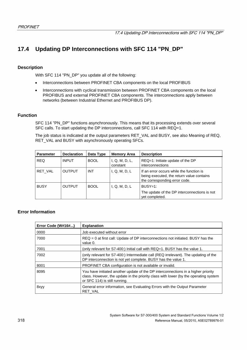
PROFINET 17.4 Updating DP Interconnections with SFC 114 "PN_DP"
System Software for S7-300/400 System and Standard Functions Volume 1/2 318 Reference Manual, 05/2010, A5E02789976-01
17.4 Updating DP Interconnections with SFC 114 "PN_DP"
Description With SFC 114 "PN_DP" you update all of the following:
• Interconnections between PROFINET CBA components on the local PROFIBUS
• Interconnections with cyclical transmission between PROFINET CBA components on the local PROFIBUS and external PROFINET CBA components. The interconnections apply between networks (between Industrial Ethernet and PROFIBUS DP).
Function SFC 114 "PN_DP" functions asynchronously. This means that its processing extends over several SFC calls. To start updating the DP interconnections, call SFC 114 with REQ=1.
The job status is indicated at the output parameters RET_VAL and BUSY, see also Meaning of REQ, RET_VAL and BUSY with asynchronously operating SFCs.
Parameter Declaration Data Type Memory Area Description
REQ INPUT BOOL I, Q, M, D, L, constant
REQ=1: Initiate update of the DP interconnections
RET_VAL OUTPUT INT I, Q, M, D, L If an error occurs while the function is being executed, the return value contains the corresponding error code.
BUSY OUTPUT BOOL I, Q, M, D, L BUSY=1: The update of the DP interconnections is not yet completed.
Error Information Error Code (W#16#...) Explanation
0000 Job executed without error 7000 REQ = 0 at first call: Update of DP interconnections not initiated. BUSY has the
value 0. 7001 (only relevant for S7-400:) Initial call with REQ=1. BUSY has the value 1. 7002 (only relevant for S7-400:) Intermediate call (REQ irrelevant). The updating of the
DP interconnection is not yet complete. BUSY has the value 1. 8001 PROFINET CBA configuration is not available or invalid. 8095 You have initiated another update of the DP interconnections in a higher priority
class. However, the update in the priority class with lower (by the operating system or SFC 114) is still running.
8xyy General error information, see Evaluating Errors with the Output Parameter RET_VAL
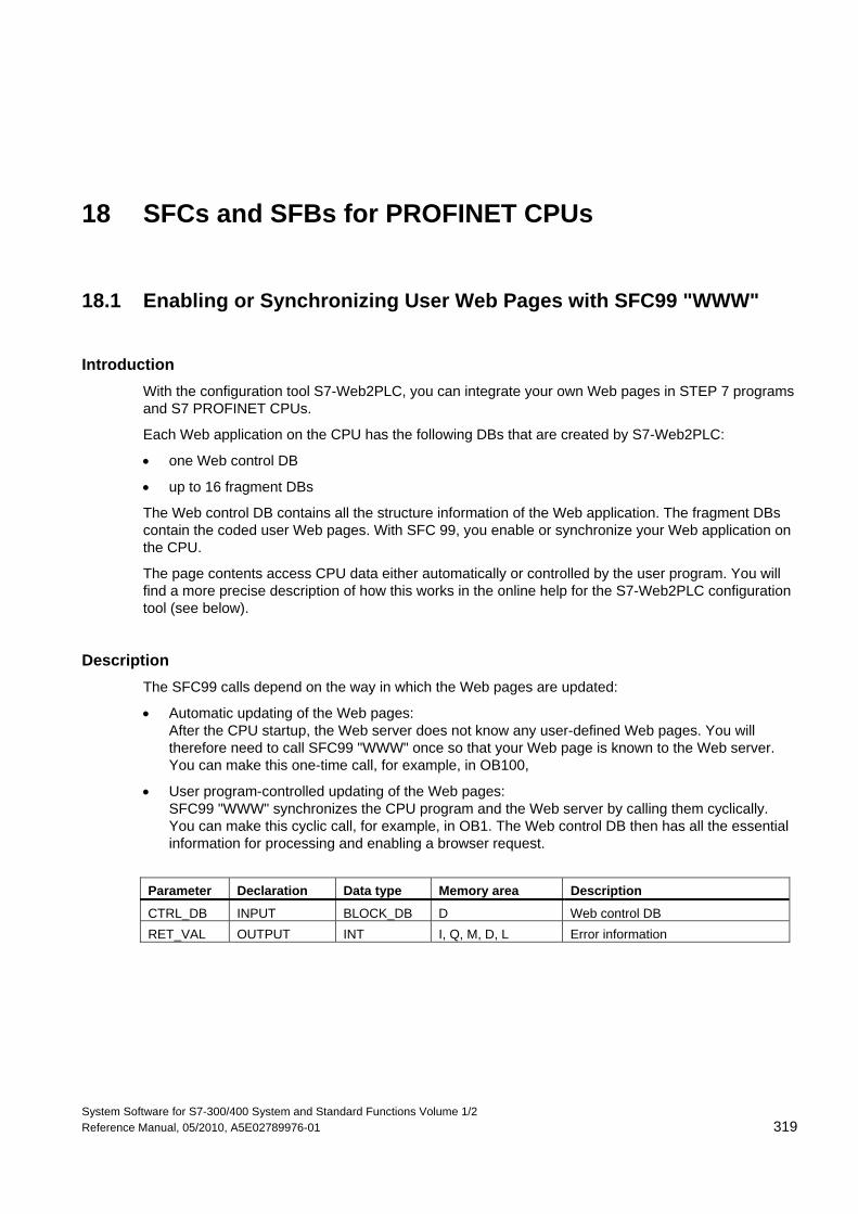
System Software for S7-300/400 System and Standard Functions Volume 1/2 Reference Manual, 05/2010, A5E02789976-01 319
18 SFCs and SFBs for PROFINET CPUs
18.1 Enabling or Synchronizing User Web Pages with SFC99 "WWW"
Introduction With the configuration tool S7-Web2PLC, you can integrate your own Web pages in STEP 7 programs and S7 PROFINET CPUs.
Each Web application on the CPU has the following DBs that are created by S7-Web2PLC:
• one Web control DB
• up to 16 fragment DBs
The Web control DB contains all the structure information of the Web application. The fragment DBs contain the coded user Web pages. With SFC 99, you enable or synchronize your Web application on the CPU.
The page contents access CPU data either automatically or controlled by the user program. You will find a more precise description of how this works in the online help for the S7-Web2PLC configuration tool (see below).
Description The SFC99 calls depend on the way in which the Web pages are updated:
• Automatic updating of the Web pages: After the CPU startup, the Web server does not know any user-defined Web pages. You will therefore need to call SFC99 "WWW" once so that your Web page is known to the Web server. You can make this one-time call, for example, in OB100,
• User program-controlled updating of the Web pages: SFC99 "WWW" synchronizes the CPU program and the Web server by calling them cyclically. You can make this cyclic call, for example, in OB1. The Web control DB then has all the essential information for processing and enabling a browser request.
Parameter Declaration Data type Memory area Description
CTRL_DB INPUT BLOCK_DB D Web control DB RET_VAL OUTPUT INT I, Q, M, D, L Error information
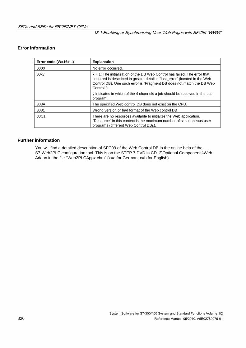
SFCs and SFBs for PROFINET CPUs 18.1 Enabling or Synchronizing User Web Pages with SFC99 "WWW"
System Software for S7-300/400 System and Standard Functions Volume 1/2 320 Reference Manual, 05/2010, A5E02789976-01
Error information Error code (W#16#...) Explanation
0000 No error occurred. 00xy x = 1: The initialization of the DB Web Control has failed. The error that
occurred is described in greater detail in "last_error" (located in the Web Control DB). One such error is "Fragment DB does not match the DB Web Control ". y indicates in which of the 4 channels a job should be received in the user program.
803A The specified Web control DB does not exist on the CPU. 8081 Wrong version or bad format of the Web control DB 80C1 There are no resources available to initialize the Web application.
"Resource" in this context is the maximum number of simultaneous user programs (different Web Control DBs).
Further information You will find a detailed description of SFC99 of the Web Control DB in the online help of the S7-Web2PLC configuration tool. This is on the STEP 7 DVD in CD_2\Optional Components\Web Addon in the file "Web2PLCAppx.chm" (x=a for German, x=b for English).
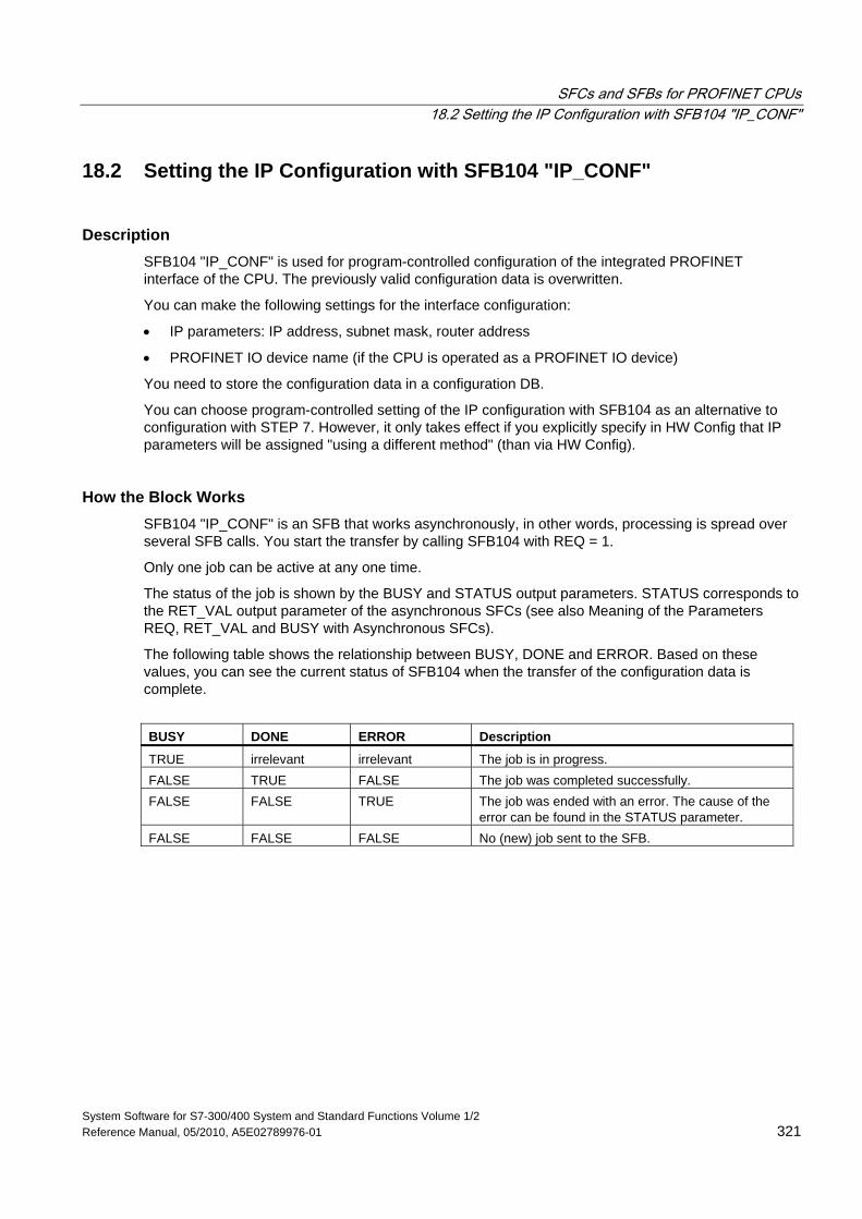
SFCs and SFBs for PROFINET CPUs 18.2 Setting the IP Configuration with SFB104 "IP_CONF"
System Software for S7-300/400 System and Standard Functions Volume 1/2 Reference Manual, 05/2010, A5E02789976-01 321
18.2 Setting the IP Configuration with SFB104 "IP_CONF"
Description SFB104 "IP_CONF" is used for program-controlled configuration of the integrated PROFINET interface of the CPU. The previously valid configuration data is overwritten.
You can make the following settings for the interface configuration:
• IP parameters: IP address, subnet mask, router address
• PROFINET IO device name (if the CPU is operated as a PROFINET IO device)
You need to store the configuration data in a configuration DB.
You can choose program-controlled setting of the IP configuration with SFB104 as an alternative to configuration with STEP 7. However, it only takes effect if you explicitly specify in HW Config that IP parameters will be assigned "using a different method" (than via HW Config).
How the Block Works SFB104 "IP_CONF" is an SFB that works asynchronously, in other words, processing is spread over several SFB calls. You start the transfer by calling SFB104 with REQ = 1.
Only one job can be active at any one time.
The status of the job is shown by the BUSY and STATUS output parameters. STATUS corresponds to the RET_VAL output parameter of the asynchronous SFCs (see also Meaning of the Parameters REQ, RET_VAL and BUSY with Asynchronous SFCs).
The following table shows the relationship between BUSY, DONE and ERROR. Based on these values, you can see the current status of SFB104 when the transfer of the configuration data is complete.
BUSY DONE ERROR Description
TRUE irrelevant irrelevant The job is in progress. FALSE TRUE FALSE The job was completed successfully. FALSE FALSE TRUE The job was ended with an error. The cause of the
error can be found in the STATUS parameter. FALSE FALSE FALSE No (new) job sent to the SFB.
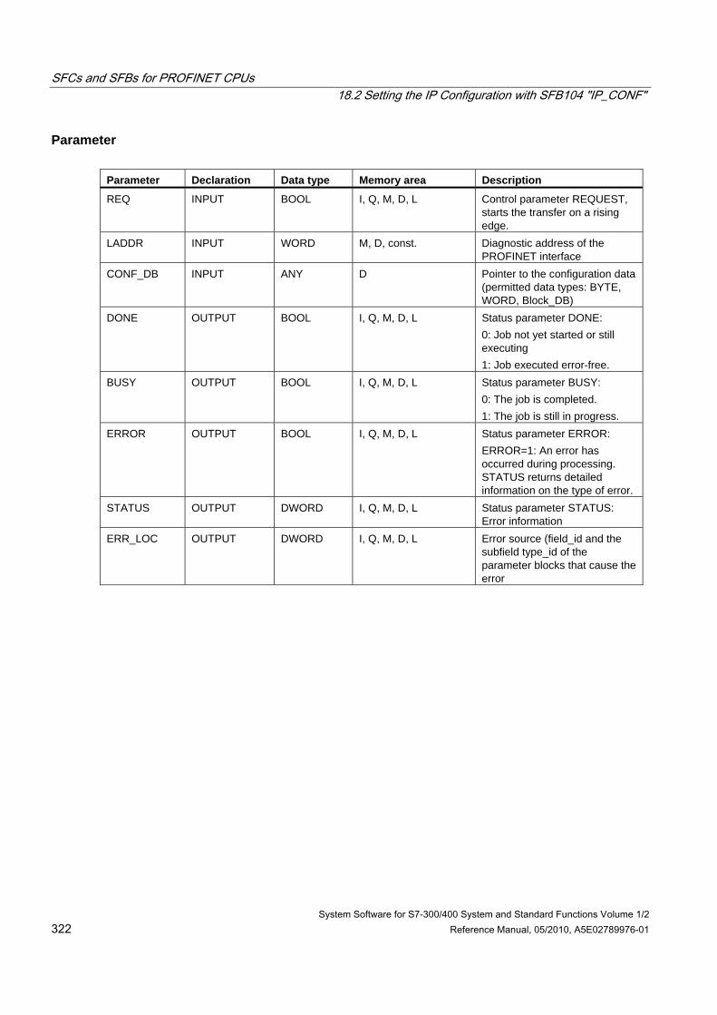
SFCs and SFBs for PROFINET CPUs 18.2 Setting the IP Configuration with SFB104 "IP_CONF"
System Software for S7-300/400 System and Standard Functions Volume 1/2 322 Reference Manual, 05/2010, A5E02789976-01
Parameter Parameter Declaration Data type Memory area Description
REQ INPUT BOOL I, Q, M, D, L Control parameter REQUEST, starts the transfer on a rising edge.
LADDR INPUT WORD M, D, const. Diagnostic address of the PROFINET interface
CONF_DB INPUT ANY D Pointer to the configuration data (permitted data types: BYTE, WORD, Block_DB)
DONE OUTPUT BOOL I, Q, M, D, L Status parameter DONE: 0: Job not yet started or still executing 1: Job executed error-free.
BUSY OUTPUT BOOL I, Q, M, D, L Status parameter BUSY: 0: The job is completed. 1: The job is still in progress.
ERROR OUTPUT BOOL I, Q, M, D, L Status parameter ERROR: ERROR=1: An error has occurred during processing. STATUS returns detailed information on the type of error.
STATUS OUTPUT DWORD I, Q, M, D, L Status parameter STATUS: Error information
ERR_LOC OUTPUT DWORD I, Q, M, D, L Error source (field_id and the subfield type_id of the parameter blocks that cause the error
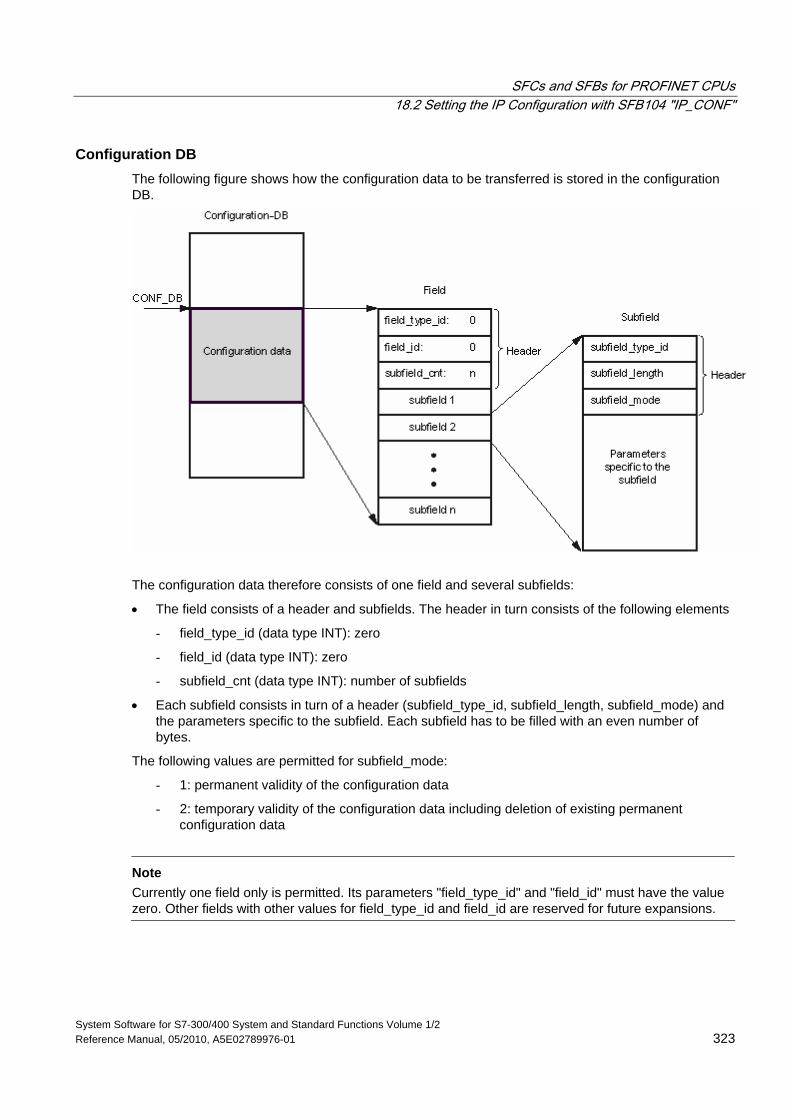
SFCs and SFBs for PROFINET CPUs 18.2 Setting the IP Configuration with SFB104 "IP_CONF"
System Software for S7-300/400 System and Standard Functions Volume 1/2 Reference Manual, 05/2010, A5E02789976-01 323
Configuration DB The following figure shows how the configuration data to be transferred is stored in the configuration DB.
The configuration data therefore consists of one field and several subfields:
• The field consists of a header and subfields. The header in turn consists of the following elements
- field_type_id (data type INT): zero
- field_id (data type INT): zero
- subfield_cnt (data type INT): number of subfields
• Each subfield consists in turn of a header (subfield_type_id, subfield_length, subfield_mode) and the parameters specific to the subfield. Each subfield has to be filled with an even number of bytes.
The following values are permitted for subfield_mode:
- 1: permanent validity of the configuration data
- 2: temporary validity of the configuration data including deletion of existing permanent configuration data
Note
Currently one field only is permitted. Its parameters "field_type_id" and "field_id" must have the value zero. Other fields with other values for field_type_id and field_id are reserved for future expansions.
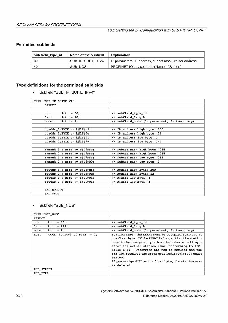
SFCs and SFBs for PROFINET CPUs 18.2 Setting the IP Configuration with SFB104 "IP_CONF"
System Software for S7-300/400 System and Standard Functions Volume 1/2 324 Reference Manual, 05/2010, A5E02789976-01
Permitted subfields sub field_type_id Name of the subfield Explanation
30 SUB_IP_SUITE_IPV4 IP parameters: IP address, subnet mask, router address 40 SUB_NOS PROFINET IO device name (Name of Station)
Type definitions for the permitted subfields • Subfield "SUB_IP_SUITE_IPV4"
TYPE "SUB_IP_SUITE_V4"
STRUCT id: int := 30; // subfield_type_id len: int := 18; // subfield_length mode: int := 1; // subfield_mode (1: permanent, 2: temporary) ipaddr_3: BYTE := b#16#c8; // IP address high byte: 200 ipaddr_2: BYTE := b#16#0c; // IP address high byte: 12 ipaddr_1: BYTE := b#16#01; // IP address low byte: 1 ipaddr_0: BYTE := b#16#90; // IP address low byte: 144 snmask_3 : BYTE := b#16#FF; // Subnet mask high byte: 255 snmask_2 : BYTE := b#16#FF; // Subnet mask high byte: 255 snmask_1 : BYTE := b#16#FF; // Subnet mask low byte: 255 snmask_0 : BYTE := b#16#00; // Subnet mask low byte: 0 router_3 : BYTE := b#16#c8; // Router high byte: 200 router_2 : BYTE := b#16#0c; // Router high byte: 12 router_1 : BYTE := b#16#01; // Router low byte: 1 router_0 : BYTE := b#16#01; // Router low byte: 1 END_STRUCT END_TYPE
• Subfield "SUB_NOS"
TYPE "SUB_NOS" STRUCT id: int := 40; // subfield_type_id len: int := 246; // subfield_length mode: int := 1; // subfield_mode (1: permanent, 2: temporary) nos: ARRAY[1..240] of BYTE := 0; Station name: The ARRAY must be occupied starting at
the first byte. If the ARRAY is longer than the station name to be assigned, you have to enter a null byte after the actual station name (conforming to IEC 61158-6-10). Otherwise the nos is refused and the SFB 104 receives the error code DW#16#C0809400 under STATUS. If you assign NULL as the first byte, the station name is deleted.
END_STRUCT END_TYPE
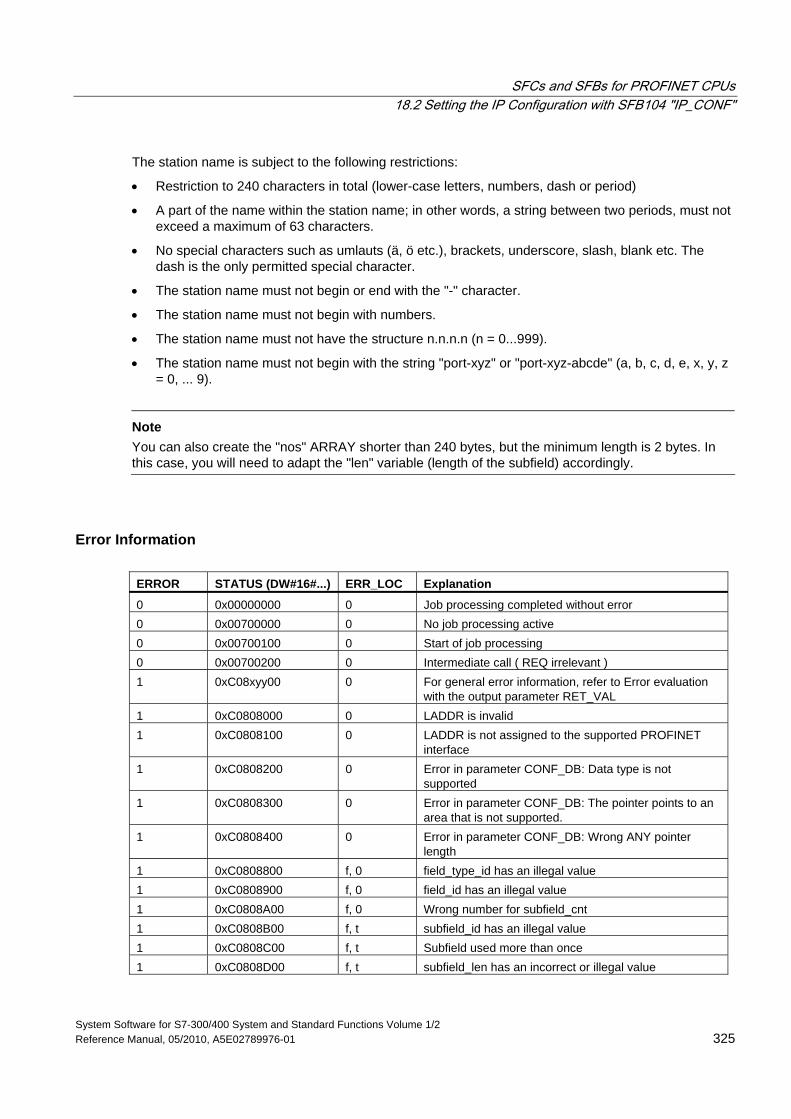
SFCs and SFBs for PROFINET CPUs 18.2 Setting the IP Configuration with SFB104 "IP_CONF"
System Software for S7-300/400 System and Standard Functions Volume 1/2 Reference Manual, 05/2010, A5E02789976-01 325
The station name is subject to the following restrictions:
• Restriction to 240 characters in total (lower-case letters, numbers, dash or period)
• A part of the name within the station name; in other words, a string between two periods, must not exceed a maximum of 63 characters.
• No special characters such as umlauts (ä, ö etc.), brackets, underscore, slash, blank etc. The dash is the only permitted special character.
• The station name must not begin or end with the "-" character.
• The station name must not begin with numbers.
• The station name must not have the structure n.n.n.n (n = 0...999).
• The station name must not begin with the string "port-xyz" or "port-xyz-abcde" (a, b, c, d, e, x, y, z = 0, ... 9).
Note
You can also create the "nos" ARRAY shorter than 240 bytes, but the minimum length is 2 bytes. In this case, you will need to adapt the "len" variable (length of the subfield) accordingly.
Error Information ERROR STATUS (DW#16#...) ERR_LOC Explanation
0 0x00000000 0 Job processing completed without error 0 0x00700000 0 No job processing active 0 0x00700100 0 Start of job processing 0 0x00700200 0 Intermediate call ( REQ irrelevant ) 1 0xC08xyy00 0 For general error information, refer to Error evaluation
with the output parameter RET_VAL 1 0xC0808000 0 LADDR is invalid 1 0xC0808100 0 LADDR is not assigned to the supported PROFINET
interface 1 0xC0808200 0 Error in parameter CONF_DB: Data type is not
supported 1 0xC0808300 0 Error in parameter CONF_DB: The pointer points to an
area that is not supported. 1 0xC0808400 0 Error in parameter CONF_DB: Wrong ANY pointer
length 1 0xC0808800 f, 0 field_type_id has an illegal value 1 0xC0808900 f, 0 field_id has an illegal value 1 0xC0808A00 f, 0 Wrong number for subfield_cnt 1 0xC0808B00 f, t subfield_id has an illegal value 1 0xC0808C00 f, t Subfield used more than once 1 0xC0808D00 f, t subfield_len has an incorrect or illegal value
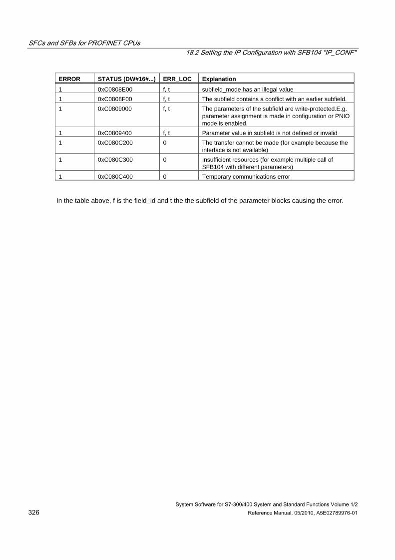
SFCs and SFBs for PROFINET CPUs 18.2 Setting the IP Configuration with SFB104 "IP_CONF"
System Software for S7-300/400 System and Standard Functions Volume 1/2 326 Reference Manual, 05/2010, A5E02789976-01
ERROR STATUS (DW#16#...) ERR_LOC Explanation
1 0xC0808E00 f, t subfield_mode has an illegal value 1 0xC0808F00 f, t The subfield contains a conflict with an earlier subfield. 1 0xC0809000 f, t The parameters of the subfield are write-protected.E.g.
parameter assignment is made in configuration or PNIO mode is enabled.
1 0xC0809400 f, t Parameter value in subfield is not defined or invalid 1 0xC080C200 0 The transfer cannot be made (for example because the
interface is not available) 1 0xC080C300 0 Insufficient resources (for example multiple call of
SFB104 with different parameters) 1 0xC080C400 0 Temporary communications error
In the table above, f is the field_id and t the the subfield of the parameter blocks causing the error.
SIMATIC
System Software for S7-300/400 System and Standard Functions Volume 2/2
Reference Manual
05/2010 A5E02790053-01
This manual is part of the documentation package with the order number: 6ES7810-4CA10-8BW1
FBs for Cyclical Access to User Data according to the PNO
19
SFCs for Global Data Communication
20
Overview over the S7 Communication and the S7 Basic Communication
21
S7 Communication
22
Communication SFCs for Non-Configured S7 Connections
23
Open Communication via Industrial Ethernet
24
Generating Block-Related Messages
25
IEC Timers and IEC Counters
26
General Information
27
SFBs for Integrated Control
28
SFBs for Compact CPUs
29
SFCs for H CPUs
30
Integrated Functions (for CPUs with integrated I/Os)
31
Plastics Techology
32
Diagnostic Data
33
System Status Lists (SSL)
34
Events
35
List of SFCs, and SFBs
36

Legal information Warning notice system
This manual contains notices you have to observe in order to ensure your personal safety, as well as to prevent damage to property. The notices referring to your personal safety are highlighted in the manual by a safety alert symbol, notices referring only to property damage have no safety alert symbol. These notices shown below are graded according to the degree of danger.
DANGER indicates that death or severe personal injury will result if proper precautions are not taken.
WARNING indicates that death or severe personal injury may result if proper precautions are not taken.
CAUTION with a safety alert symbol, indicates that minor personal injury can result if proper precautions are not taken.
CAUTION without a safety alert symbol, indicates that property damage can result if proper precautions are not taken.
NOTICE indicates that an unintended result or situation can occur if the corresponding information is not taken into account.
If more than one degree of danger is present, the warning notice representing the highest degree of danger will be used. A notice warning of injury to persons with a safety alert symbol may also include a warning relating to property damage.
Qualified Personnel The product/system described in this documentation may be operated only by personnel qualified for the specific task in accordance with the relevant documentation for the specific task, in particular its warning notices and safety instructions. Qualified personnel are those who, based on their training and experience, are capable of identifying risks and avoiding potential hazards when working with these products/systems.
Proper use of Siemens products Note the following:
WARNING Siemens products may only be used for the applications described in the catalog and in the relevant technical documentation. If products and components from other manufacturers are used, these must be recommended or approved by Siemens. Proper transport, storage, installation, assembly, commissioning, operation and maintenance are required to ensure that the products operate safely and without any problems. The permissible ambient conditions must be adhered to. The information in the relevant documentation must be observed.
Trademarks All names identified by ® are registered trademarks of the Siemens AG. The remaining trademarks in this publication may be trademarks whose use by third parties for their own purposes could violate the rights of the owner.
Disclaimer of Liability We have reviewed the contents of this publication to ensure consistency with the hardware and software described. Since variance cannot be precluded entirely, we cannot guarantee full consistency. However, the information in this publication is reviewed regularly and any necessary corrections are included in subsequent editions.
Siemens AG Industry Sector Postfach 48 48 90026 NÜRNBERG GERMANY
A5E02790053-01 Ⓟ 02/2010
Copyright © Siemens AG 2010. Technical data subject to change
System Software for S7-300/400 System and Standard Functions Volume 2/2 Reference Manual, 05/2010, A5E02790053-01 329
Contents
19 FBs for Cyclical Access to User Data according to the PNO .............................................................335 19.1 Introduction to the FBs for Cyclical Access to User Data according to the PNO ......................335 19.2 Read All Inputs of a DP Standard Slave/PROFINET IO Device with FB 20 "GETIO"...............336 19.3 Write All Outputs of a DP Standard Slave/PROFINET IO Device with FB 21 "SETIO" ............337 19.4 Read a Part of the Inputs of a DP Standard Slave/PROFINET IO Device with FB 22
"GETIO_PART"..........................................................................................................................338 19.5 Write a Part of the Outputs of a DP Standard Slave/PROFINET IO Device with FB 23
"SETIO_PART" ..........................................................................................................................340 20 SFCs for Global Data Communication ..................................................................................................343
20.1 Sending a GD Packet with SFC 60 "GD_SND" .........................................................................343 20.2 Programmed Acceptance of a Received GD Packet with SFC 61 "GD_RCV" .........................346
21 Overview over the S7 Communication and the S7 Basic Communication .......................................349 21.1 Differences between the Blocks of the S7 Communication and the S7 Basic Communication 349 21.2 Data Consistency.......................................................................................................................352 21.3 Overview of the S7 Communication Blocks...............................................................................354 21.4 Overview of the Blocks for the S7 Basic Communication..........................................................357
22 S7 Communication..................................................................................................................................361 22.1 Common Parameters of the SFBs/FBs and SFCs/FCs for S7 Communication........................361 22.2 Startup Routine of SFBs for Configured S7 Connections..........................................................366 22.3 How SFBs React to Problems ...................................................................................................368 22.4 Uncoordinated Sending of Data with SFB 8/FB 8 "USEND" .....................................................370 22.5 Uncoordinated Receiving of Data with SFB/FB 9 "URCV" ........................................................374 22.6 Sending Segmented Data with SFB/FB 12 "BSEND"................................................................378 22.7 Receiving Segmented Data with SFB/FB 13 "BRCV" ...............................................................382 22.8 Uncoordinated Sending of Data with FB28 "USEND_E"...........................................................386 22.9 Uncoordinated Reception of Data with FB29 "URCV_E" ..........................................................389 22.10 Reading Data from a Remote CPU with FB34 "GET_E" ...........................................................392 22.11 Writing Data to a Remote CPU with FB35 "PUT_E"..................................................................395 22.12 Writing Data to a Remote CPU with SFB/FB 15 "PUT" .............................................................398 22.13 Read Data from a Remote CPU with SFB/FB 14 "GET" ...........................................................402 22.14 Sending Data to a Printer with SFB 16 "PRINT"........................................................................405 22.15 Initiating a Warm or Cold Restart on a Remote Device with SFB 19 "START".........................412 22.16 Changing a Remote Device to the STOP State with SFB 20 "STOP".......................................415 22.17 Initiating a Hot Restart on a Remote Device with SFB 21 "RESUME" ......................................418 22.18 Querying the Status of a Remote Partner with SFB 22 "STATUS" ...........................................420 22.19 Receiving the Status Change of a Remote Device with SFB 23 "USTATUS" ..........................422 22.20 Querying the Status of the Connection Belonging to an SFB Instance with
SFC 62 "CONTROL"..................................................................................................................425 22.21 Querying the Connection Status with FC 62 "C_CNTRL" .........................................................428
Contents
System Software for S7-300/400 System and Standard Functions Volume 2/2 330 Reference Manual, 05/2010, A5E02790053-01
23 Communication SFCs for Non-Configured S7 Connections ..............................................................431 23.1 Common Parameters of the Communication SFCs...................................................................431 23.2 Error Information of the Communication SFCs for Non-Configured S7 Connections................433 23.3 Sending Data to a Communication Partner outside the Local S7 Station with
SFC 65 "X_SEND" .....................................................................................................................437 23.4 Receiving Data from a Communication Partner outside the Local S7 Station with
SFC 66 "X_RCV" .......................................................................................................................439 23.5 Writing Data to a Communication Partner outside the Local S7 Station with
SFC 68 "X_PUT"........................................................................................................................444 23.6 Reading Data from a Communication Partner outside the Local S7 Station with
SFC 67 "X_GET"........................................................................................................................446 23.7 Aborting an Existing Connection to a Communication Partner outside the
Local S7 Station with SFC 69 "X_ABORT"................................................................................448 23.8 Reading Data from a Communication Partner within the Local S7 Station with
SFC 72 "I_GET" .........................................................................................................................449 23.9 Writing Data to a Communication Partner within the Local S7 Station with SFC 73 "I_PUT" ...451 23.10 Aborting an Existing Connection to a Communication Partner within the Local S7 Station
with SFC 74 "I_ABORT".............................................................................................................453 24 Open Communication via Industrial Ethernet ......................................................................................455
24.1 Overview ....................................................................................................................................455 24.2 Function of FBs for Open Communication via Industrial Ethernet.............................................456 24.3 Assigning Parameters for Communications Connections with TCP and ISO-on-TCP..............461 24.4 Assigning Parameters for the Local Communications Access Point with UDP.........................467 24.5 Structure of the Address Information for the Remote Partner with UDP ...................................469 24.6 Relationship between CPU and Protocol Variant Used (connection_type) and
Transferable Data Length ..........................................................................................................470 24.7 Examples of Parameters for Communications Connections .....................................................471 24.8 Establishing a Connection with FB 65 "TCON"..........................................................................482 24.9 Terminating a Connection with FB 66 "TDISCON"....................................................................486 24.10 Sending Data via TCP and ISO on TCP with FB 63 "TSEND"..................................................488 24.11 Receiving Data via TCP and ISO on TCP with FB 64 "TRCV"..................................................491 24.12 Sending Data via UDP with FB 67 "TUSEND"...........................................................................495 24.13 Receiving Data via UDP with FB 68 "TURCV" ..........................................................................498 24.14 Linking to a Third-Party System with FB 210 "FW_TCP" using the FETCH and
WRITE Services via TCP...........................................................................................................501 24.15 Linking to a Third-Party System with FB FB 220 "FW_IOT" using the FETCH and
WRITE Services via ISO-on-TCP ..............................................................................................502 25 Generating Block-Related Messages ....................................................................................................503
25.1 Introduction to Generating Block-Related Messages with SFBs ...............................................503 25.2 Generating Block-Related Messages without Acknowledgment with SFB 36 "NOTIFY" ..........507 25.3 Generating Block Related Messages without Acknowledgement Display with SFB 31
"NOTIFY_8P" .............................................................................................................................509 25.4 Generating Block-Related Messages with Acknowledgment with SFB 33 "ALARM"................512 25.5 Generating Block-Related Messages with Associated Values for Eight Signals with
SFB 35 "ALARM_8P".................................................................................................................515 25.6 Generating Block-Related Messages without Associated Values for Eight Signals with
SFB 34 "ALARM_8" ...................................................................................................................518 25.7 Sending Archive Data with SFB 37 "AR_SEND" .......................................................................520 25.8 Disabling Block-Related, Symbol-Related and Group Status Messages with
SFC 10 "DIS_MSG" ...................................................................................................................523
Contents
System Software for S7-300/400 System and Standard Functions Volume 2/2 A5E02790053-01 331
25.9 Enabling Block-Related, Symbol-Related, and Group Status Messages with SFC 9 "EN_MSG" ......................................................................................................................525
25.10 Startup Behavior of the SFBs for Generating Block-Related Messages ...................................527 25.11 How the SFBs for Generating Block-Related Messages React to Problems ............................528 25.12 Introduction to Generating Block-Related Messages with SFCs...............................................529 25.13 Generating Acknowledgeable Block-Related Messages with SFC 17 "ALARM_SQ" and
Permanently Acknowledged Block-Related Messages with SFC 18 "ALARM_S" ....................532 25.14 Querying the Acknowledgment Status of the Last ALARM_SQ/ALARM_DQ Entering Event
Message with SFC 19 "ALARM_SC".........................................................................................535 25.15 Generating Acknowledgeable and Permanently Acknowledged Block Related Messages
with SFCs 107 "ALARM_DQ" and 108 "ALARM_D" .................................................................537 25.16 Reading Dynamic System Resources with SFC 105 "READ_SI" .............................................540 25.17 Reading Dynamic System Resources with SFC 106 "DEL_SI" ................................................544
26 IEC Timers and IEC Counters ................................................................................................................547 26.1 Generating a Pulse with SFB 3 "TP"..........................................................................................547 26.2 Generating an On Delay with SFB 4 "TON" ..............................................................................549 26.3 Generating an Off Delay with SFB 5 "TOF"...............................................................................550 26.4 Counting Up with SFB 0 "CTU"..................................................................................................551 26.5 Counting Down with SFB 1 "CTD" .............................................................................................552 26.6 Up / Down Count with SFB 2 "CTUD"........................................................................................553
27 General Information ................................................................................................................................555 27.1 Overview ....................................................................................................................................555 27.2 Technical Data of the IEC Functions .........................................................................................557 27.3 Date and Time as Complex Data Types....................................................................................559 27.4 Time-of-Day Functions...............................................................................................................560 27.5 Comparing DATE_AND_TIME Variables ..................................................................................564 27.6 Editing STRING Variables .........................................................................................................567 27.7 Comparing STRING Variables...................................................................................................572 27.8 Converting Data Type Formats..................................................................................................575 27.9 Editing Number Values ..............................................................................................................578
28 SFBs for Integrated Control ...................................................................................................................581 28.1 Continuous Control with SFB 41/FB 41 "CONT_C"...................................................................581 28.2 Step Control with SFB 42/FB 42 "CONT_S"..............................................................................589 28.3 Pulse Generation with SFB 43/FB 43 "PULSEGEN".................................................................595 28.4 Example of the PULSEGEN Block.............................................................................................606
29 SFBs for Compact CPUs ........................................................................................................................609 29.1 Positioning With Analog Output Using SFB 44 "Analog"...........................................................609 29.2 Positioning with Digital Output Using SFB 46 "DIGITAL" ..........................................................623 29.3 Controlling the Counter with SFB 47 "COUNT" .........................................................................636 29.4 Controlling the Frequency Measurement with SFB 48 "FREQUENC" ......................................641 29.5 Controlling Pulse Width Modulation with SFB 49 "PULSE".......................................................646 29.6 Sending Data (ASCII, 3964(R)) with SFB 60 "SEND_PTP" ......................................................649 29.7 Receiving Data (ASCII, 3964(R)) with SFB 61 "RCV_PTP"......................................................652 29.8 Deleting the Receive Buffer (ASCII, 3964(R)) with SFB 62 "RES_RCVB"................................655 29.9 Sending Data (512(R)) with SFB 63 "SEND_RK"......................................................................657 29.10 Fetching Data (RK 512) with SFB 64 "FETCH RK" ...................................................................661 29.11 Receiving and Providing Data (RK 512) with SFB 65 "SERVE_RK".........................................666 29.12 Additional Error Information of the SFBs 60 to 65 .....................................................................671
Contents
System Software for S7-300/400 System and Standard Functions Volume 2/2 332 Reference Manual, 05/2010, A5E02790053-01
30 SFCs for H CPUs .....................................................................................................................................679 30.1 Controlling Operation in H Systems with SFC 90 "H_CTRL" ....................................................679
31 Integrated Functions (for CPUs with integrated I/Os) .........................................................................683 31.1 SFB 29 (HS_COUNT) ................................................................................................................683 31.2 SFB 30 (FREQ_MES) ................................................................................................................685 31.3 SFB 38 (HSC_A_B) ...................................................................................................................686 31.4 SFB 39 (POS) ............................................................................................................................687
32 Plastics Techology ..................................................................................................................................689 32.1 SFC 63 (AB_CALL)....................................................................................................................689
33 Diagnostic Data .......................................................................................................................................691 33.1 Overview of the Structure of Diagnostic Data............................................................................691 33.2 Diagnostic Data..........................................................................................................................691 33.3 Structure of Channel-Specific Diagnostic Data..........................................................................694
34 System Status Lists (SSL)......................................................................................................................697 34.1 Overview of the System Status Lists (SSL) ...............................................................................697 34.2 Structure of a Partial SSL List ....................................................................................................699 34.3 SSL-ID........................................................................................................................................700 34.4 Possible Partial System Status Lists..........................................................................................701 34.5 SSL-ID W#16#xy11 - Module Identification ...............................................................................702 34.6 SSL-ID W#16#xy12 - CPU Characteristics................................................................................703 34.7 SSL-ID W#16#xy13 - Memory Areas.........................................................................................706 34.8 SSL-ID W#16#xy14 - System Areas..........................................................................................708 34.9 SSL-ID W#16#xy15 - Block Types.............................................................................................710 34.10 SSL-ID W#16#xy1C - Component Identification........................................................................711 34.11 SSL-ID W#16#xy22 - Interrupt Status........................................................................................716 34.12 SSL ID W#16#xy25 - Assignment of Process Image Partitions to OBs ....................................719 34.13 SSL-ID W#16#xy32 - Communication Status Data ...................................................................722 34.14 Data Record of the Partial List Extract with SSL-ID W#16#0132 Index W#16#0005................723 34.15 Data Record of the Partial List Extract with SSL-ID W#16#0132 Index W#16#0008................724 34.16 Data Record of the Partial List Extract with SSL-ID W#16#0132 Index W#16#000B ...............726 34.17 Data Record of the Partial List Extract with SSL-ID W#16#0132 Index W#16#000C ...............727 34.18 Data Record of the Partial List Extract with SSL-ID W#16#0232 Index W#16#0004................728 34.19 SSL-ID W#16#xy71 - H CPU Group Information.......................................................................729 34.20 SSL-ID W#16#xy74 - Status of the Module LEDs .....................................................................732 34.21 SSL-ID W#16#xy75 - Switched DP Slaves in the H System .....................................................735 34.22 SSL-ID W#16#xy90 - DP Master System Information ...............................................................737 34.23 SSL-ID W#16#xy91 - Module Status Information ......................................................................739 34.24 SSL-ID W#16#xy92 - Rack / Station Status Information ...........................................................745 34.25 SSL-ID W#16#0x94 - Status Information for Rack/Station ........................................................749 34.26 SSL-ID W#16#xy95 - Extended DP Master System / PROFINET IO System Information .......751 34.27 SSL-ID W#16#xy96 - PROFINET IO and PROFIBUS DP Module Status Information .............753 34.28 SSL-ID W#16#xy9C - Tool Changer Information (PROFINET IO) ............................................756 34.29 SSL-ID W#16#xyA0 - Diagnostic Buffer ....................................................................................760 34.30 SSL-ID W#16#00B1 - Module Diagnostic Information...............................................................762 34.31 SSL-ID W#16#00B2 - Diagnostic Data Record 1 with Physical Address ..................................764 34.32 SSL-ID W#16#00B3 - Module Diagnostic Data with Logical Base Address..............................765 34.33 SSL-ID W#16#00B4 - Diagnostic Data of a DP Slave...............................................................766
Contents
System Software for S7-300/400 System and Standard Functions Volume 2/2 A5E02790053-01 333
35 Events.......................................................................................................................................................767 35.1 Events and Event ID ..................................................................................................................767 35.2 Event Class 1 - Standard OB Events.........................................................................................768 35.3 Event Class 2 - Synchronous Errors..........................................................................................769 35.4 Event Class 3 - Asynchronous Errors........................................................................................770 35.5 Event Class 4 - Stop Events and Other Mode Changes ...........................................................773 35.6 Event Class 5 - Mode Run-time Events.....................................................................................777 35.7 Event Class 6 - Communication Events ....................................................................................778 35.8 Event Class 7 - H/F Events........................................................................................................780 35.9 Event Class 8 - Diagnostic Events for Modules.........................................................................783 35.10 Event Class 9 - Standard User Events ......................................................................................785 35.11 Event Classes A and B - Free User Events...............................................................................787 35.12 Reserved Event Classes............................................................................................................787
36 List of SFCs, and SFBs...........................................................................................................................789 36.1 List of SFCs, Sorted Numerically ...............................................................................................789 36.2 List of SFCs, Sorted Alphabetically............................................................................................792 36.3 List of SFBs, Sorted Numerically ...............................................................................................795 36.4 List of SFBs, Sorted Alphabetically............................................................................................797
Bibliography.......................................................................................................................................................799
Glossary .............................................................................................................................................................801
Index ...................................................................................................................................................................819

Contents
System Software for S7-300/400 System and Standard Functions Volume 2/2 334 Reference Manual, 05/2010, A5E02790053-01
System Software for S7-300/400 System and Standard Functions Volume 2/2 Reference Manual, 05/2010, A5E02790053-01 335
19 FBs for Cyclical Access to User Data according to the PNO
19.1 Introduction to the FBs for Cyclical Access to User Data according to the PNO
Overview The FBs for cyclical access to user data according to the PNO (PROFIBUS Nutzerorganisation e.V./German PROFIBUS User Organization) are the following blocks (meaning given in parentheses):
• FB 20 "GETIO" (read all inputs of a DP standard slave/PROFINET IO device)
• FB 21 "SETIO" (write all outputs of a DP standard slave/PROFINET IO device)
• FB 22 "GETIO_PART" (read a part of the inputs of a DP standard slave/PROFINET IO device)
• FB 23 "SETIO_PART" (write a part of the outputs of a DP standard slave/PROFINET IO device)
Interfaces to the FBs for cyclical access to user data as per the PNO The interfaces to the FBs named above are identical to those FBs defined with the same names in the standard "PROFIBUS and PROFINET Communication Function Blocks on PROFIBUS DP and PROFINET IO".
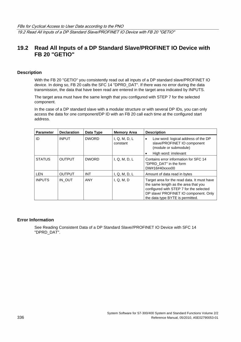
FBs for Cyclical Access to User Data according to the PNO 19.2 Read All Inputs of a DP Standard Slave/PROFINET IO Device with FB 20 "GETIO"
System Software for S7-300/400 System and Standard Functions Volume 2/2 336 Reference Manual, 05/2010, A5E02790053-01
19.2 Read All Inputs of a DP Standard Slave/PROFINET IO Device with FB 20 "GETIO"
Description With the FB 20 "GETIO" you consistently read out all inputs of a DP standard slave/PROFINET IO device. In doing so, FB 20 calls the SFC 14 "DPRD_DAT". If there was no error during the data transmission, the data that have been read are entered in the target area indicated by INPUTS.
The target area must have the same length that you configured with STEP 7 for the selected component.
In the case of a DP standard slave with a modular structure or with several DP IDs, you can only access the data for one component/DP ID with an FB 20 call each time at the configured start address.
Parameter Declaration Data Type Memory Area Description
ID INPUT DWORD I, Q, M, D, L constant
• Low word: logical address of the DP slave/PROFINET IO component (module or submodule)
• High word: irrelevant STATUS OUTPUT DWORD I, Q, M, D, L Contains error information for SFC 14
"DPRD_DAT" in the form DW#16#40xxxx00
LEN OUTPUT INT I, Q, M, D, L Amount of data read in bytes INPUTS IN_OUT ANY I, Q, M, D Target area for the read data. It must have
the same length as the area that you configured with STEP 7 for the selected DP slave/ PROFINET IO component. Only the data type BYTE is permitted.
Error Information See Reading Consistent Data of a DP Standard Slave//PROFINET IO Device with SFC 14 "DPRD_DAT".
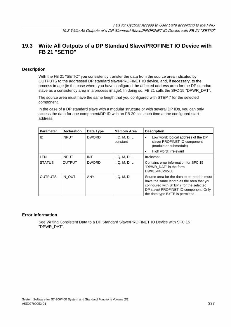
FBs for Cyclical Access to User Data according to the PNO 19.3 Write All Outputs of a DP Standard Slave/PROFINET IO Device with FB 21 "SETIO"
System Software for S7-300/400 System and Standard Functions Volume 2/2 A5E02790053-01 337
19.3 Write All Outputs of a DP Standard Slave/PROFINET IO Device with FB 21 "SETIO"
Description With the FB 21 "SETIO" you consistently transfer the data from the source area indicated by OUTPUTS to the addressed DP standard slave/PROFINET IO device, and, if necessary, to the process image (in the case where you have configured the affected address area for the DP standard slave as a consistency area in a process image). In doing so, FB 21 calls the SFC 15 "DPWR_DAT".
The source area must have the same length that you configured with STEP 7 for the selected component.
In the case of a DP standard slave with a modular structure or with several DP IDs, you can only access the data for one component/DP ID with an FB 20 call each time at the configured start address.
Parameter Declaration Data Type Memory Area Description
ID INPUT DWORD I, Q, M, D, L, constant
• Low word: logical address of the DP slave/ PROFINET IO component (module or submodule)
• High word: irrelevant LEN INPUT INT I, Q, M, D, L Irrelevant STATUS OUTPUT DWORD I, Q, M, D, L Contains error information for SFC 15
"DPWR_DAT" in the form DW#16#40xxxx00
OUTPUTS IN_OUT ANY I, Q, M, D Source area for the data to be read. It must have the same length as the area that you configured with STEP 7 for the selected DP slave/ PROFINET IO component. Only the data type BYTE is permitted.
Error Information See Writing Consistent Data to a DP Standard Slave/PROFINET IO Device with SFC 15 "DPWR_DAT".
FBs for Cyclical Access to User Data according to the PNO 19.4 Read a Part of the Inputs of a DP Standard Slave/PROFINET IO Device with FB 22 "GETIO_PART"
System Software for S7-300/400 System and Standard Functions Volume 2/2 338 Reference Manual, 05/2010, A5E02790053-01
19.4 Read a Part of the Inputs of a DP Standard Slave/PROFINET IO Device with FB 22 "GETIO_PART"
Description With the FB 22 "GETIO_PART" you consistently read a part of the process image area belonging to a DP standard slave/PROFINET IO device. In doing so, FB 22 calls the SFC 81 "UBLKMOV".
Note
You must assign a process image partition for inputs to the OB in which FB 22 "GETIO_PART" is called. Furthermore, before calling FB 22 you must add the associated DP standard slave or the associated PROFINET IO device to this process image partition for inputs. If your CPU does not recognize any process image partitions or you want to call FB 22 in OB 1, you must add the associated DP standard slave or the associated PROFINET IO device to this process image partition for inputs before calling FB 22.
You use the OFFSET and LEN parameters to specify the portion of the process image area to be read for the components addressed by means of their ID.
If there was no error during the data transmission, ERROR receives the value FALSE, and the data that have been read are entered in the target area indicated by INPUTS.
If there was an error during the data transmission, ERROR receives the value TRUE, and STATUS receives the SFC 81 error information "UBLKMOV".
If the target area (INPUTS parameter) is smaller than LEN, then as many bytes as INPUTS can accept are transferred. ERROR receives the value FALSE. If the target area is greater than LEN, then the first LEN bytes in the target area are written. ERROR receives the value FALSE.
Note
The FB 22 "GETIO_PART" does not check the process image for inputs for delimiters between data belonging to different PROFIBUS DP or PROFINET IO components. Because of this, you yourself must make sure that the process image area specified by means of OFFSET and LEN belongs to one component. Reading of data for more than one component cannot be guaranteed for future systems and compromises the transferability to systems from other manufacturers.
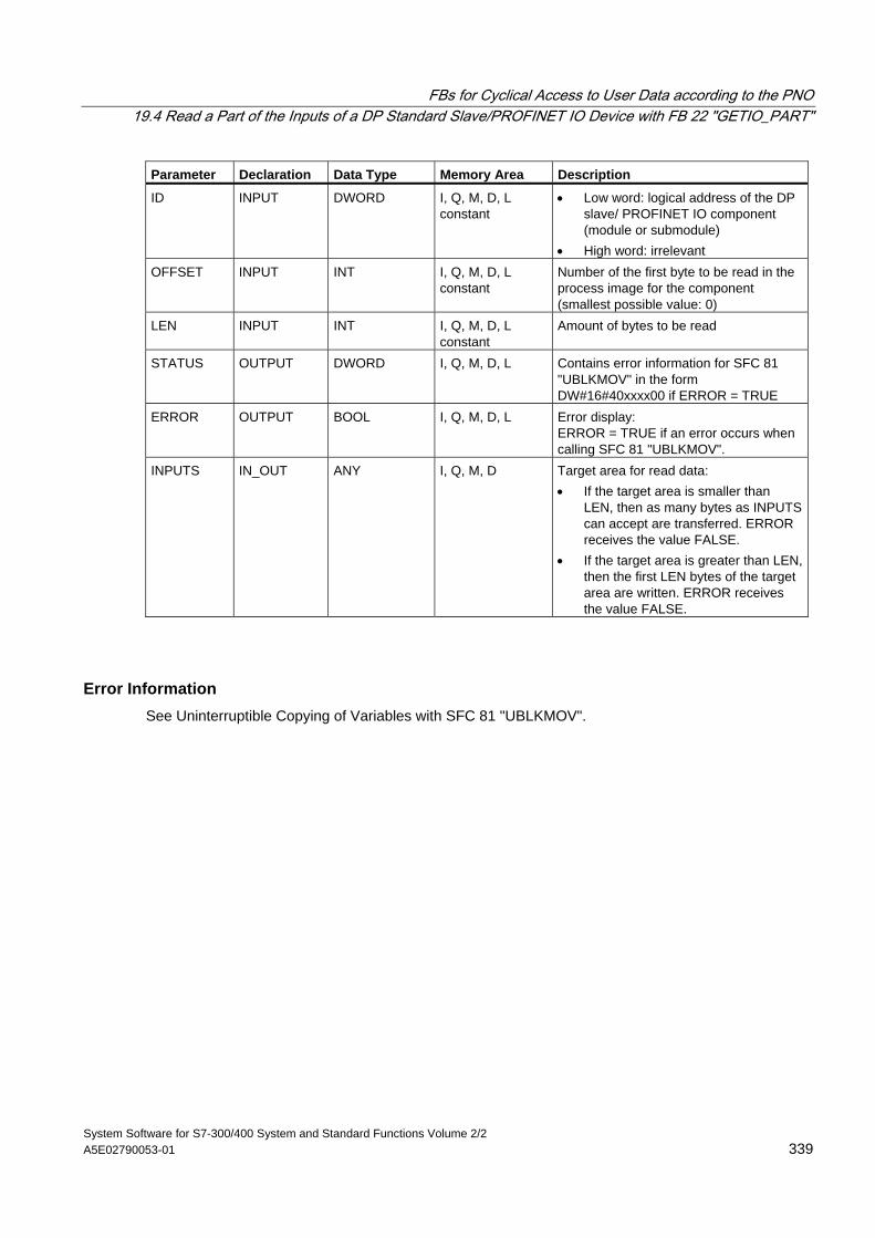
FBs for Cyclical Access to User Data according to the PNO 19.4 Read a Part of the Inputs of a DP Standard Slave/PROFINET IO Device with FB 22 "GETIO_PART"
System Software for S7-300/400 System and Standard Functions Volume 2/2 A5E02790053-01 339
Parameter Declaration Data Type Memory Area Description
ID INPUT DWORD I, Q, M, D, L constant
• Low word: logical address of the DP slave/ PROFINET IO component (module or submodule)
• High word: irrelevant OFFSET INPUT INT I, Q, M, D, L
constant Number of the first byte to be read in the process image for the component (smallest possible value: 0)
LEN INPUT INT I, Q, M, D, L constant
Amount of bytes to be read
STATUS OUTPUT DWORD I, Q, M, D, L Contains error information for SFC 81 "UBLKMOV" in the form DW#16#40xxxx00 if ERROR = TRUE
ERROR OUTPUT BOOL I, Q, M, D, L Error display: ERROR = TRUE if an error occurs when calling SFC 81 "UBLKMOV".
INPUTS IN_OUT ANY I, Q, M, D Target area for read data: • If the target area is smaller than
LEN, then as many bytes as INPUTS can accept are transferred. ERROR receives the value FALSE.
• If the target area is greater than LEN, then the first LEN bytes of the target area are written. ERROR receives the value FALSE.
Error Information See Uninterruptible Copying of Variables with SFC 81 "UBLKMOV".
FBs for Cyclical Access to User Data according to the PNO 19.5 Write a Part of the Outputs of a DP Standard Slave/PROFINET IO Device with FB 23 "SETIO_PART"
System Software for S7-300/400 System and Standard Functions Volume 2/2 340 Reference Manual, 05/2010, A5E02790053-01
19.5 Write a Part of the Outputs of a DP Standard Slave/PROFINET IO Device with FB 23 "SETIO_PART"
Description With the FB 23 "SETIO_PART" you transfer data from the source area indicated by OUTPUTS into a part of the process image area belonging to a DP standard slave/PROFINET IO device. In doing so, FB 23 calls the SFC 81 "UBLKMOV".
Note
You must assign a process image partition for outputs to the OB in which FB 23 "SETIO_PART" is called. Furthermore, before calling FB 23 you must add the associated DP standard slave or the associated PROFINET IO device to this process image partition for outputs. If your CPU does not recognize any process image partitions or you want to call FB 23 in OB 1, you must add the associated DP standard slave or the associated PROFINET IO device to this process image partition for outputs before calling FB 23.
You use the OFFSET and LEN parameters to specify the portion of the process image area to be written for the components addressed by means of their ID.
If there was no error during the data transmission, ERROR receives the value FALSE.
If there was an error during the data transmission, ERROR receives the value TRUE, and STATUS receives the SFC 81 error information "UBLKMOV".
If the source area (OUTPUTS parameter) is smaller than LEN, then as many bytes as OUTPUTS contains are transferred. ERROR receives the value FALSE. If the source area is greater than LEN, then the first LEN bytes are transferred from OUTPUTS. ERROR receives the value FALSE.
Note
The FB 23 "SETIO_PART" does not check the process image for inputs for delimiters between data that belong to different PROFIBUS DP or PROFINET IO components. Because of this, you yourself must make sure that the process image area specified by means of OFFSET and LEN belongs to one component. Writing of data for more than one component cannot be guaranteed for future systems and compromises the transferability to systems from other manufacturers.
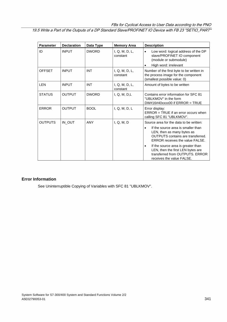
FBs for Cyclical Access to User Data according to the PNO 19.5 Write a Part of the Outputs of a DP Standard Slave/PROFINET IO Device with FB 23 "SETIO_PART"
System Software for S7-300/400 System and Standard Functions Volume 2/2 A5E02790053-01 341
Parameter Declaration Data Type Memory Area Description
ID INPUT DWORD I, Q, M, D, L, constant
• Low word: logical address of the DP slave/PROFINET IO component (module or submodule)
• High word: irrelevant OFFSET INPUT INT I, Q, M, D, L,
constant Number of the first byte to be written in the process image for the component (smallest possible value: 0)
LEN INPUT INT I, Q, M, D, L, constant
Amount of bytes to be written
STATUS OUTPUT DWORD I, Q, M, D,L Contains error information for SFC 81 "UBLKMOV" in the form DW#16#40xxxx00 if ERROR = TRUE
ERROR OUTPUT BOOL I, Q, M, D, L Error display: ERROR = TRUE if an error occurs when calling SFC 81 "UBLKMOV".
OUTPUTS IN_OUT ANY I, Q, M, D Source area for the data to be written: • If the source area is smaller than
LEN, then as many bytes as OUTPUTS contains are transferred. ERROR receives the value FALSE.
• If the source area is greater than LEN, then the first LEN bytes are transferred from OUTPUTS. ERROR receives the value FALSE.
Error Information See Uninterruptible Copying of Variables with SFC 81 "UBLKMOV".
FBs for Cyclical Access to User Data according to the PNO 19.5 Write a Part of the Outputs of a DP Standard Slave/PROFINET IO Device with FB 23 "SETIO_PART"
System Software for S7-300/400 System and Standard Functions Volume 2/2 342 Reference Manual, 05/2010, A5E02790053-01
System Software for S7-300/400 System and Standard Functions Volume 2/2 Reference Manual, 05/2010, A5E02790053-01 343
20 SFCs for Global Data Communication
20.1 Sending a GD Packet with SFC 60 "GD_SND"
Description With SFC 60 "GD_SND" (global data send), the data of a GD packet are collected and then sent on the path specified in the GD packet. The GD packet must already have been configured with STEP 7.
SFC 60 "GD_SND" can be called at any point in the user program.
The scan rate and the collection and sending of the data by the system at the cycle checkpoint are not influenced by SFC 60 calls.
Interrupt ability SFC 60 "GD_SND" can be interrupted by higher priority classes. It is also possible that SFC 60 is called again for the same GD packet in the higher priority class.
The data are then collected and sent in the higher priority class. When the program returns to the interrupted SFC, this is terminated immediately and the data that have already been collected are discarded.
This procedure means that during the processing of the highest priority class, consistent data are transferred (consistency in the sense defined for global data).
Data Consistency with GD The following rules apply to the consistency of the data collected from the various memory areas and sent.
The following are consistent:
• The simple data types (bit, byte, word, and double word)
• An array of the data types byte, word, and double word up to a maximum length depending on the specific CPU.
SFCs for Global Data Communication 20.1 Sending a GD Packet with SFC 60 "GD_SND"
System Software for S7-300/400 System and Standard Functions Volume 2/2 344 Reference Manual, 05/2010, A5E02790053-01
Ensuring Consistency for an Entire GD Packet A GD packet on the CPU sending the data has a structure that does not automatically guarantee that the collected data are consistent. This is, for example, the case when the packet consists of an array of bytes and the number of bytes exceeds the maximum length for the specific CPU.
If, however, you require consistency for the entire GD packet, follow the procedure below in your program:
• Disable or delay the occurrence of higher priority interrupts and asynchronous errors by calling SFC 39 "DIS_IRT" or SFC 41 "DIS_AIRT."
• Call SFC 60 "GD_SND."
• Enable the higher priority interrupts and asynchronous errors again by calling SFC 40 "EN_IRT" or SFC 42 "EN_AIRT."
Parameter Declaration Data Type Memory Area Description
CIRCLE_ID INPUT BYTE I, Q, M, D, L, constant
Number of the GD circle in which the GD packet to be sent is located. You specify this number when configuring the global data with STEP 7. Permitted values: 1 to 16. The maximum number of possible GD circles can be found in the technical data of your CPU.
BLOCK_ID INPUT BYTE I, Q, M, D, L, constant
Number of the GD packet to be sent in the selected GD circle. This number is set during configuration of the global data by STEP 7. Permitted values: 1 to 3. The maximum number of possible GD circles can be found in the technical data of your CPU.
RET_VAL OUTPUT INT I, Q, M, D, L Error information
SFCs for Global Data Communication 20.1 Sending a GD Packet with SFC 60 "GD_SND"
System Software for S7-300/400 System and Standard Functions Volume 2/2 A5E02790053-01 345
Error Information Error Code (W#16#...) Explanation
0000 No error occurred. 8081 The GD packet selected with the parameters CIRCLE_ID and BLOCK_ID is not
configured. 8082 Illegal value for the parameters CIRCLE_ID or BLOCK_ID or for both parameters. 8083 An error occurred during the execution of the SFC. The type of error is entered
in the variable configured for the status information. This can be evaluated by your program.
8084 The execution of the SFC was terminated prematurely because SFC 60 was called again for the same GD packet in a higher priority class (see ”Interrupt ability”).
8085 An error occurred entering the status information in the configured variable. 8xyy General error information, see Evaluating Errors with the Output Parameter
RET_VAL
Note
Following each SFC 60 call, you should evaluate the corresponding GD packet status and, if necessary, reset it.
SFCs for Global Data Communication 20.2 Programmed Acceptance of a Received GD Packet with SFC 61 "GD_RCV"
System Software for S7-300/400 System and Standard Functions Volume 2/2 346 Reference Manual, 05/2010, A5E02790053-01
20.2 Programmed Acceptance of a Received GD Packet with SFC 61 "GD_RCV"
Description With SFC 61 "GD_RCV" (global data receive), the data from an incoming GD frame for exactly one GD packet are retrieved and entered in the received GD packet. This must already have been configured with STEP 7.
SFC 61 "GD_SND" can be called at any point in the user program.
The scan rate and the retrieving of the data by the system at the cycle checkpoint are not influenced by SFC 61 calls.
Interrupt ability SFC 61 can be interrupted by higher priority classes, however, only so that the data consistency defined for global data remains guaranteed. If the processing of the function is interrupted, it is possible that SFC 61 is called again for the same GD packet in the higher priority class.
The data are then entered in the receive GD packet in the higher priority class. When the program returns to the interrupted SFC, this is terminated immediately.
Data Consistency with GD The following rules apply to the consistency of the data entered in the various memory areas.
The following are consistent:
• The simple data types (bit, byte, word, and double word)
• An array of the data types byte, word, and double word up to a maximum length specific to the receiving CPU.
SFCs for Global Data Communication 20.2 Programmed Acceptance of a Received GD Packet with SFC 61 "GD_RCV"
System Software for S7-300/400 System and Standard Functions Volume 2/2 A5E02790053-01 347
Ensuring Consistency for an Entire GD Packet A GD packet on a receiving CPU has a structure that does not automatically guarantee that its data originate from one and the same frame. This is, for example, the case when the packet consists of three GD elements.
If, however, you require consistency for the entire GD packet, follow the procedure below in your program:
• Disable or delay the occurrence of higher priority interrupts and asynchronous errors by calling SFC 39 "DIS_IRT" or SFC 41 "DIS_AIRT."
• Call SFC 60 "GD_SND."
• Enable the higher priority interrupts and asynchronous errors again by calling SFC 40 "EN_IRT" or SFC 42 "EN_AIRT."
Parameter Declaration Data Type Memory Area Description
CIRCLE_ID INPUT BYTE I, Q, M, D, L, constant
Number of the GD circle into which the incoming GD packet will be entered. This number is specified during configuration of the global data with STEP 7. Permitted values: 1 to 16. The maximum number of possible GD circles can be found in the technical data for your CPU.
BLOCK_ID INPUT BYTE I, Q, M, D, L, constant
Number of the GD packet in the selected GD circle in which the incoming data will be entered. This number is specified during configuration of the global data by STEP 7. Permitted values: 1 to 3. The maximum number of possible GD circles can be found in the technical data for your CPU.
RET_VAL OUTPUT INT I, Q, M, D, L Error information
SFCs for Global Data Communication 20.2 Programmed Acceptance of a Received GD Packet with SFC 61 "GD_RCV"
System Software for S7-300/400 System and Standard Functions Volume 2/2 348 Reference Manual, 05/2010, A5E02790053-01
Error Information Error Code (W#16#...) Explanation
0000 No error occurred. 8081 The GD packet selected with the parameters CIRCLE_ID and BLOCK_ID is not
configured. 8082 Illegal value for the parameters CIRCLE_ID or BLOCK_ID or for both
parameters. 8083 An error occurred during the execution of the SFC. The type of error is entered in
the variable configured for the status information. This can be evaluated by your program.
8084 The execution of the SFC was terminated prematurely because SFC 61 was called again for the same GD packet in a higher priority class (see ”Interrupt ability”).
8085 An error occurred entering the status information in the configured variable. 8xyy General error information, see Evaluating Errors with the Output Parameter
RET_VAL
Note
Following each SFC 61 call, you should evaluate the corresponding GD packet status and, if necessary, reset it.
System Software for S7-300/400 System and Standard Functions Volume 2/2 Reference Manual, 05/2010, A5E02790053-01 349
21 Overview over the S7 Communication and the S7 Basic Communication
21.1 Differences between the Blocks of the S7 Communication and the S7 Basic Communication
Selection Criteria Apart from global data communication, there are two other methods of exchanging data between CPUs/FMs of SIMATIC S7 programmable controllers:
• Data exchange using communication SFCs for non-configured S7 connections
• Data exchange using communication SFBs for configured S7 connections
Which method you choose, depends on the SIMATIC S7 programmable controller you are using (S7-300, S7-400) and on other parameters for data exchange. The following table contains a list of criteria on which you can base your selection.
Criteria Communication SFCs for Non-
Configured S7 Connections Communication SFBs for Configured S7 Connections
Availability of the blocks S7-300 and S7-400 as SFCs S7-300 as FBs and FC S7-400 as SFBs and SFC
Communication connections
The connection is not configured. It is established when the SFC is active. The connection either remains established after the data have been transferred or it is terminated parameter-controlled. If a connection cannot be established temporarily, the corresponding job cannot be sent.
Connections are configured permanently in the system configuration.
Change to the STOP mode
If the CPU that initiated the data transfer changes to STOP mode, all the connections it established are terminated.
The connection is maintained in the STOP mode.
Several connections to a partner
At any one time, a maximum of one connection is possible to a communication partner.
You can establish several connections to the same partner.
Address range Modules can be addressed in the local station or in the MPI subnet
Modules can be addressed on the MPI network, on PROFIBUS or on Industrial Ethernet
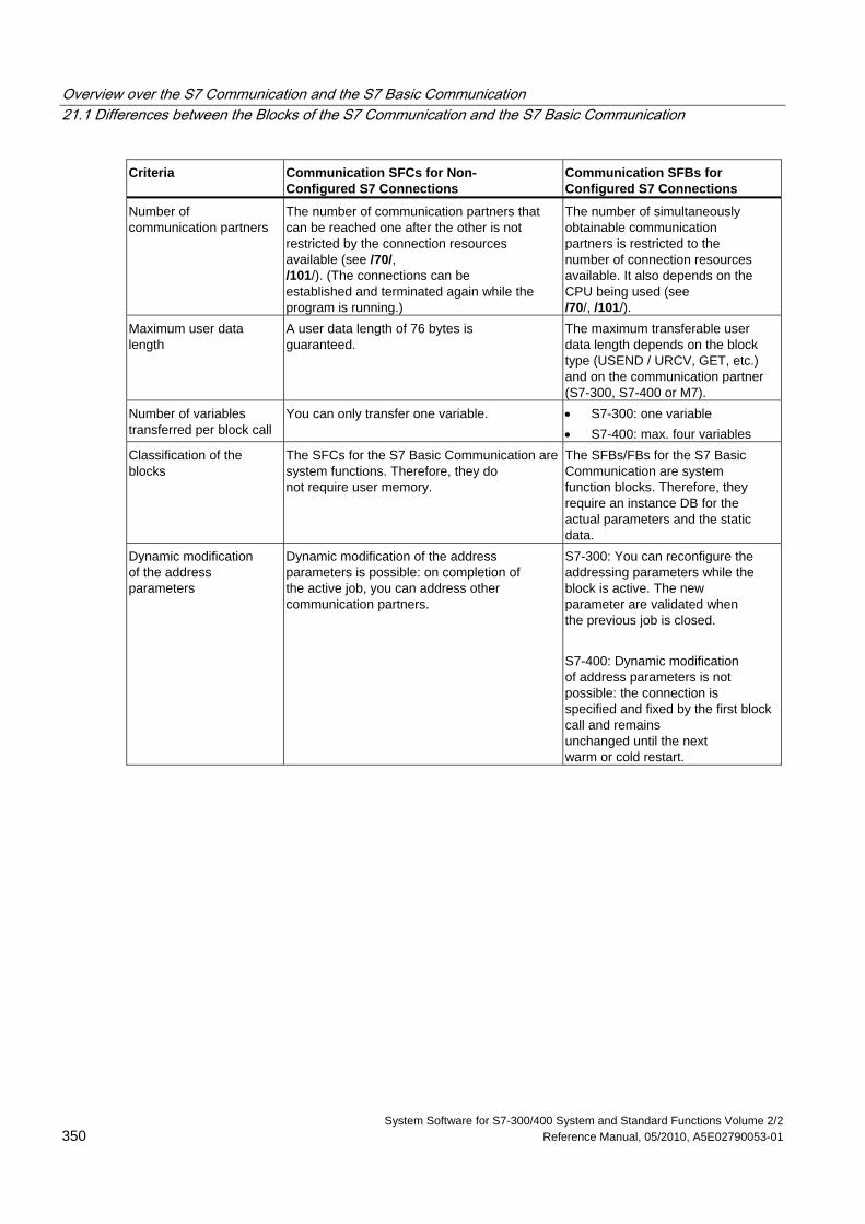
Overview over the S7 Communication and the S7 Basic Communication 21.1 Differences between the Blocks of the S7 Communication and the S7 Basic Communication
System Software for S7-300/400 System and Standard Functions Volume 2/2 350 Reference Manual, 05/2010, A5E02790053-01
Criteria Communication SFCs for Non- Configured S7 Connections
Communication SFBs for Configured S7 Connections
Number of communication partners
The number of communication partners that can be reached one after the other is not restricted by the connection resources available (see /70/, /101/). (The connections can be established and terminated again while the program is running.)
The number of simultaneously obtainable communication partners is restricted to the number of connection resources available. It also depends on the CPU being used (see /70/, /101/).
Maximum user data length
A user data length of 76 bytes is guaranteed.
The maximum transferable user data length depends on the block type (USEND / URCV, GET, etc.) and on the communication partner (S7-300, S7-400 or M7).
Number of variables transferred per block call
You can only transfer one variable. • S7-300: one variable • S7-400: max. four variables
Classification of the blocks
The SFCs for the S7 Basic Communication are system functions. Therefore, they do not require user memory.
The SFBs/FBs for the S7 Basic Communication are system function blocks. Therefore, they require an instance DB for the actual parameters and the static data.
Dynamic modification of the address parameters
Dynamic modification of the address parameters is possible: on completion of the active job, you can address other communication partners.
S7-300: You can reconfigure the addressing parameters while the block is active. The new parameter are validated when the previous job is closed. S7-400: Dynamic modification of address parameters is not possible: the connection is specified and fixed by the first block call and remains unchanged until the next warm or cold restart.
Overview over the S7 Communication and the S7 Basic Communication 21.1 Differences between the Blocks of the S7 Communication and the S7 Basic Communication
System Software for S7-300/400 System and Standard Functions Volume 2/2 A5E02790053-01 351
Implementation of IEC 61131-5 with S7-400 The IEC standard 61131-5 is realized with the following blocks:
• USEND(SFB 8)/URCV(SFB 9)
• BSEND(SFB 12)/BRCV(SFB 13)
• PUT(SFB 15)/GET(SFB 14) corresponds to READ/WRITE
• STATUS(SFB 22)/USTATUS(SFB 23)
• ALARM(SFB 33)
• NOTIFY(SFB 36)
• START (SFB 19), STOP (SFB 20) and RESUME (SFB 21) realizes a call interface for the program control functions.
Implementation of IEC 61131-5 with S7-300 The IEC standard 61131-5 is realized with the following blocks:
• USEND(SFB 8)/URCV(SFB 9)
• BSEND(SFB 12)/BRCV(SFB 13)
• PUT(SFB 15)/GET(SFB 14) corresponds to READ/WRITE
• USEND_E(FB28)/URCV_E(FB29)
• PUT_E(FB35)/GET_E(FB34) corresponds to READ/WRITE
Overview over the S7 Communication and the S7 Basic Communication 21.2 Data Consistency
System Software for S7-300/400 System and Standard Functions Volume 2/2 352 Reference Manual, 05/2010, A5E02790053-01
21.2 Data Consistency
Definition The size of the data area which can be modified simultaneously by concurrent processes is called the consistent data area. Data areas which are larger than the consistent data area can thus be falsified as a whole. This means that a data area which belongs together and which is larger than consistent data area can consist in part of new and of old consistent data blocks at the same time.
Example AN inconsistency can arise if a communication block is interrupted, for example, by a hardware interrupt OB with a higher priority. If the user program in this OB now changes the data which have already been processed in part by the communication block, the transferred data originate:
• IN part from the time before the hardware interrupt was processed
• And in part from the time after the hardware interrupt was processed
• This means that these data are inconsistent (not coherent).
Effect If larger packages of data are to be transferred in a consistent form, the transfer may not be interrupted. This can, for example, increase the interrupt reaction time in the CPU. This means: The higher the quantity of data which have to be transferred absolutely consistently, the longer the interrupt reaction time of a system.
Data Consistency at SIMATIC If the user program includes a communication function, for example BSEND/BRCV, which accesses common data, access to this data area can, for example, be coordinated by using the parameter "DONE”. The data consistency of the communication areas which are transferred locally with a communication block can therefore be ensured in the user program. However, in the case of S7 communication functions, for example PUT/GET or write/read via OP communication the size of the consistent data area must already be taken into consideration during the programming or configuration stage, since no communication block is available in the user program of the target device (server) to send synchronized communication data to the user program. At the S7-300 and C7-300 (exception: CPU 318-2 DP) the communication data are copied consistently into the user memory in blocks of 32 bytes in the cycle checkpoint of the operating system. Data consistency is not guaranteed for larger data areas. If a defined data consistency is required, the communication data in the user program may not exceed 32 bytes (maximum of 8 bytes, depending on the version). In the S7-400 by contrast the communication data are not processed in the cycle checkpoint, but in fixed time slices during the program cycle. The consistency of a variable is ensured by the system. These communication areas can then be accessed consistently using the PUT/GET functions or reading/writing of variables, for example by an OP on an OS.
Overview over the S7 Communication and the S7 Basic Communication 21.2 Data Consistency
System Software for S7-300/400 System and Standard Functions Volume 2/2 A5E02790053-01 353
Recommendation For further information on data consistency, please refer to the information describing individual blocks as well as the manual Communication with SIMATIC.
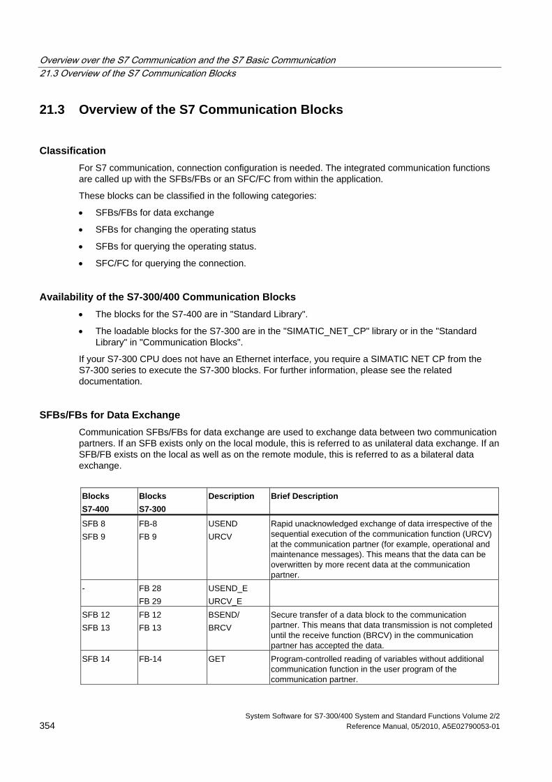
Overview over the S7 Communication and the S7 Basic Communication 21.3 Overview of the S7 Communication Blocks
System Software for S7-300/400 System and Standard Functions Volume 2/2 354 Reference Manual, 05/2010, A5E02790053-01
21.3 Overview of the S7 Communication Blocks
Classification For S7 communication, connection configuration is needed. The integrated communication functions are called up with the SFBs/FBs or an SFC/FC from within the application.
These blocks can be classified in the following categories:
• SFBs/FBs for data exchange
• SFBs for changing the operating status
• SFBs for querying the operating status.
• SFC/FC for querying the connection.
Availability of the S7-300/400 Communication Blocks • The blocks for the S7-400 are in "Standard Library".
• The loadable blocks for the S7-300 are in the "SIMATIC_NET_CP" library or in the "Standard Library" in "Communication Blocks".
If your S7-300 CPU does not have an Ethernet interface, you require a SIMATIC NET CP from the S7-300 series to execute the S7-300 blocks. For further information, please see the related documentation.
SFBs/FBs for Data Exchange Communication SFBs/FBs for data exchange are used to exchange data between two communication partners. If an SFB exists only on the local module, this is referred to as unilateral data exchange. If an SFB/FB exists on the local as well as on the remote module, this is referred to as a bilateral data exchange.
Blocks S7-400
Blocks S7-300
Description Brief Description
SFB 8 SFB 9
FB-8 FB 9
USEND URCV
Rapid unacknowledged exchange of data irrespective of the sequential execution of the communication function (URCV) at the communication partner (for example, operational and maintenance messages). This means that the data can be overwritten by more recent data at the communication partner.
- FB 28 FB 29
USEND_E URCV_E
SFB 12 SFB 13
FB 12 FB 13
BSEND/ BRCV
Secure transfer of a data block to the communication partner. This means that data transmission is not completed until the receive function (BRCV) in the communication partner has accepted the data.
SFB 14 FB-14 GET Program-controlled reading of variables without additional communication function in the user program of the communication partner.
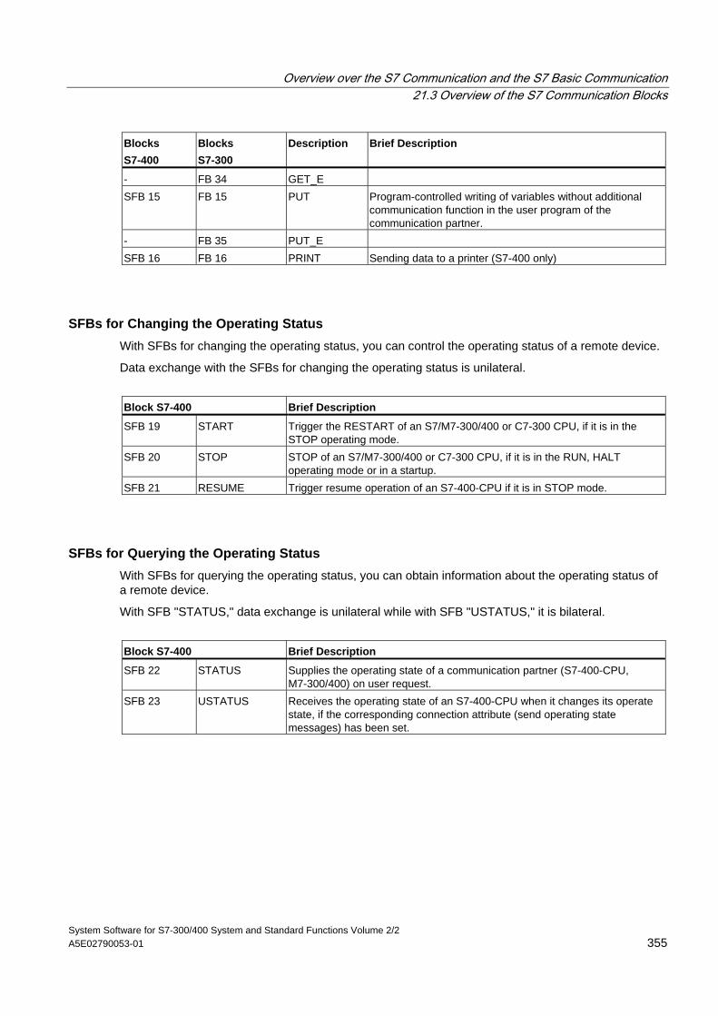
Overview over the S7 Communication and the S7 Basic Communication 21.3 Overview of the S7 Communication Blocks
System Software for S7-300/400 System and Standard Functions Volume 2/2 A5E02790053-01 355
Blocks S7-400
Blocks S7-300
Description Brief Description
- FB 34 GET_E SFB 15 FB 15 PUT Program-controlled writing of variables without additional
communication function in the user program of the communication partner.
- FB 35 PUT_E SFB 16 FB 16 PRINT Sending data to a printer (S7-400 only)
SFBs for Changing the Operating Status With SFBs for changing the operating status, you can control the operating status of a remote device.
Data exchange with the SFBs for changing the operating status is unilateral.
Block S7-400 Brief Description
SFB 19 START Trigger the RESTART of an S7/M7-300/400 or C7-300 CPU, if it is in the STOP operating mode.
SFB 20 STOP STOP of an S7/M7-300/400 or C7-300 CPU, if it is in the RUN, HALT operating mode or in a startup.
SFB 21 RESUME Trigger resume operation of an S7-400-CPU if it is in STOP mode.
SFBs for Querying the Operating Status With SFBs for querying the operating status, you can obtain information about the operating status of a remote device.
With SFB "STATUS," data exchange is unilateral while with SFB "USTATUS," it is bilateral.
Block S7-400 Brief Description
SFB 22 STATUS Supplies the operating state of a communication partner (S7-400-CPU, M7-300/400) on user request.
SFB 23 USTATUS Receives the operating state of an S7-400-CPU when it changes its operate state, if the corresponding connection attribute (send operating state messages) has been set.
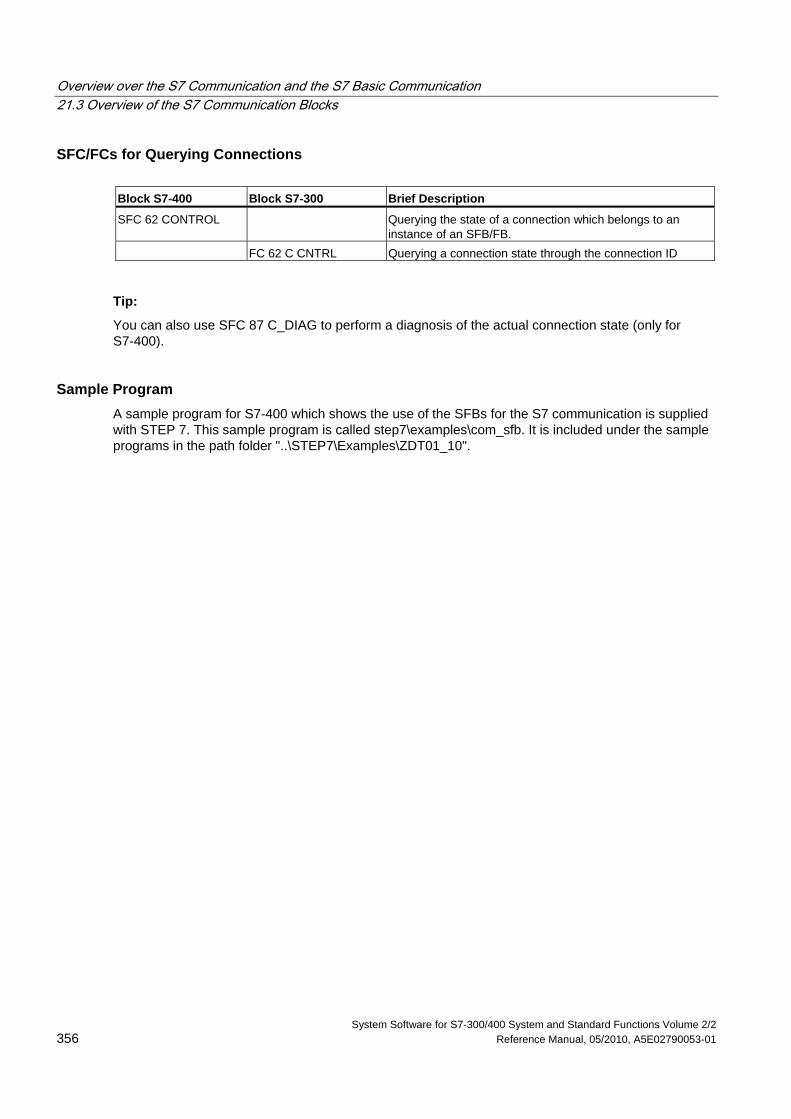
Overview over the S7 Communication and the S7 Basic Communication 21.3 Overview of the S7 Communication Blocks
System Software for S7-300/400 System and Standard Functions Volume 2/2 356 Reference Manual, 05/2010, A5E02790053-01
SFC/FCs for Querying Connections Block S7-400 Block S7-300 Brief Description
SFC 62 CONTROL Querying the state of a connection which belongs to an instance of an SFB/FB.
FC 62 C CNTRL Querying a connection state through the connection ID
Tip:
You can also use SFC 87 C_DIAG to perform a diagnosis of the actual connection state (only for S7-400).
Sample Program A sample program for S7-400 which shows the use of the SFBs for the S7 communication is supplied with STEP 7. This sample program is called step7\examples\com_sfb. It is included under the sample programs in the path folder "..\STEP7\Examples\ZDT01_10".
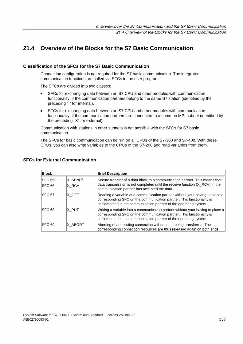
Overview over the S7 Communication and the S7 Basic Communication 21.4 Overview of the Blocks for the S7 Basic Communication
System Software for S7-300/400 System and Standard Functions Volume 2/2 A5E02790053-01 357
21.4 Overview of the Blocks for the S7 Basic Communication
Classification of the SFCs for the S7 Basic Communication Connection configuration is not required for the S7 basic communication. The integrated communication functions are called via SFCs in the user program.
The SFCs are divided into two classes:
• SFCs for exchanging data between an S7 CPU and other modules with communication functionality, if the communication partners belong to the same S7 station (identified by the preceding "I” for internal).
• SFCs for exchanging data between an S7 CPU and other modules with communication functionality, if the communication partners are connected to a common MPI subnet (identified by the preceding "X” for external).
Communication with stations in other subnets is not possible with the SFCs for S7 basic communication.
The SFCs for basic communication can be run on all CPUs of the S7-300 and S7-400. With these CPUs, you can also write variables to the CPUs of the S7-200 and read variables from them.
SFCs for External Communication Block Brief Description
SFC 65/ SFC 66
X_SEND/ X_RCV
Secure transfer of a data block to a communication partner. This means that data transmission is not completed until the receive function (X_RCV) in the communication partner has accepted the data.
SFC 67 X_GET Reading a variable of a communication partner without your having to place a corresponding SFC on the communication partner. This functionality is implemented in the communication partner of the operating system.
SFC 68 X_PUT Writing a variable into a communication partner without your having to place a corresponding SFC on the communication partner. This functionality is implemented in the communication partner of the operating system.
SFC 69 X_ABORT Aborting of an existing connection without data being transferred. The corresponding connection resources are thus released again on both ends.
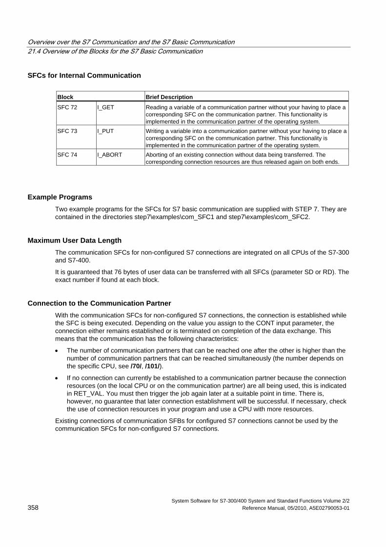
Overview over the S7 Communication and the S7 Basic Communication 21.4 Overview of the Blocks for the S7 Basic Communication
System Software for S7-300/400 System and Standard Functions Volume 2/2 358 Reference Manual, 05/2010, A5E02790053-01
SFCs for Internal Communication Block Brief Description
SFC 72 I_GET Reading a variable of a communication partner without your having to place a corresponding SFC on the communication partner. This functionality is implemented in the communication partner of the operating system.
SFC 73 I_PUT Writing a variable into a communication partner without your having to place a corresponding SFC on the communication partner. This functionality is implemented in the communication partner of the operating system.
SFC 74 I_ABORT Aborting of an existing connection without data being transferred. The corresponding connection resources are thus released again on both ends.
Example Programs Two example programs for the SFCs for S7 basic communication are supplied with STEP 7. They are contained in the directories step7\examples\com_SFC1 and step7\examples\com_SFC2.
Maximum User Data Length The communication SFCs for non-configured S7 connections are integrated on all CPUs of the S7-300 and S7-400.
It is guaranteed that 76 bytes of user data can be transferred with all SFCs (parameter SD or RD). The exact number if found at each block.
Connection to the Communication Partner With the communication SFCs for non-configured S7 connections, the connection is established while the SFC is being executed. Depending on the value you assign to the CONT input parameter, the connection either remains established or is terminated on completion of the data exchange. This means that the communication has the following characteristics:
• The number of communication partners that can be reached one after the other is higher than the number of communication partners that can be reached simultaneously (the number depends on the specific CPU, see /70/, /101/).
• If no connection can currently be established to a communication partner because the connection resources (on the local CPU or on the communication partner) are all being used, this is indicated in RET_VAL. You must then trigger the job again later at a suitable point in time. There is, however, no guarantee that later connection establishment will be successful. If necessary, check the use of connection resources in your program and use a CPU with more resources.
Existing connections of communication SFBs for configured S7 connections cannot be used by the communication SFCs for non-configured S7 connections.
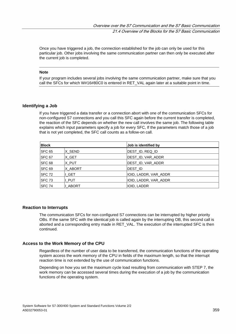
Overview over the S7 Communication and the S7 Basic Communication 21.4 Overview of the Blocks for the S7 Basic Communication
System Software for S7-300/400 System and Standard Functions Volume 2/2 A5E02790053-01 359
Once you have triggered a job, the connection established for the job can only be used for this particular job. Other jobs involving the same communication partner can then only be executed after the current job is completed.
Note
If your program includes several jobs involving the same communication partner, make sure that you call the SFCs for which W#16#80C0 is entered in RET_VAL again later at a suitable point in time.
Identifying a Job If you have triggered a data transfer or a connection abort with one of the communication SFCs for non-configured S7 connections and you call this SFC again before the current transfer is completed, the reaction of the SFC depends on whether the new call involves the same job. The following table explains which input parameters specify a job for every SFC, If the parameters match those of a job that is not yet completed, the SFC call counts as a follow-on call.
Block Job is identified by
SFC 65 X_SEND DEST_ID, REQ_ID SFC 67 X_GET DEST_ID, VAR_ADDR SFC 68 X_PUT DEST_ID, VAR_ADDR SFC 69 X_ABORT DEST_ID SFC 72 I_GET IOID, LADDR, VAR_ADDR SFC 73 I_PUT IOID, LADDR, VAR_ADDR SFC 74 I_ABORT IOID, LADDR
Reaction to Interrupts The communication SFCs for non-configured S7 connections can be interrupted by higher priority OBs. If the same SFC with the identical job is called again by the interrupting OB, this second call is aborted and a corresponding entry made in RET_VAL. The execution of the interrupted SFC is then continued.
Access to the Work Memory of the CPU Regardless of the number of user data to be transferred, the communication functions of the operating system access the work memory of the CPU in fields of the maximum length, so that the interrupt reaction time is not extended by the use of communication functions.
Depending on how you set the maximum cycle load resulting from communication with STEP 7, the work memory can be accessed several times during the execution of a job by the communication functions of the operating system.
Overview over the S7 Communication and the S7 Basic Communication 21.4 Overview of the Blocks for the S7 Basic Communication
System Software for S7-300/400 System and Standard Functions Volume 2/2 360 Reference Manual, 05/2010, A5E02790053-01
Client Changes to STOP If the CPU that initiated a job (and therefore established the connection) changes to STOP during a data transfer, all the connections it established are terminated.
Making Program Changes All parts of your program that immediately affect the calls for communication SFCs for non-configured S7 connections must only be modified in the STOP mode. This includes, in particular, deleting FCs, FBs, or OBs containing calls for communication SFCs for non-configured S7 connections.
After modifying the program, you must perform a warm or cold restart.
Not following these rules can lead to resources remaining assigned and the programmable controller being subsequently in an undefined state.
System Software for S7-300/400 System and Standard Functions Volume 2/2 Reference Manual, 05/2010, A5E02790053-01 361
22 S7 Communication
22.1 Common Parameters of the SFBs/FBs and SFCs/FCs for S7 Communication
Classification The parameters of communication SFBs/FBs for configured S7 connections can be divided into the following five categories according to their functions:
1. Control parameters are used to activate a block.
2. Addressing parameters are used to address the remote communication partner.
3. Send parameters point to the data areas that are to be sent to the remote partner.
4. Receive parameters point to the data areas where the data received from remote partners will be entered.
5. Status parameters are used to monitor whether the block has completed its task without error or for the analysis of any errors that have occurred.
Control Parameters Data exchange will only be activated if the appropriate control parameters have a defined signal state (for example are set) when the SFB/FB is called or when the signal state has undergone a specific change since the previous SFB/FB call (for example, positive edge).
Note on S7-300
For the first call, set the parameter REQ to FALSE.
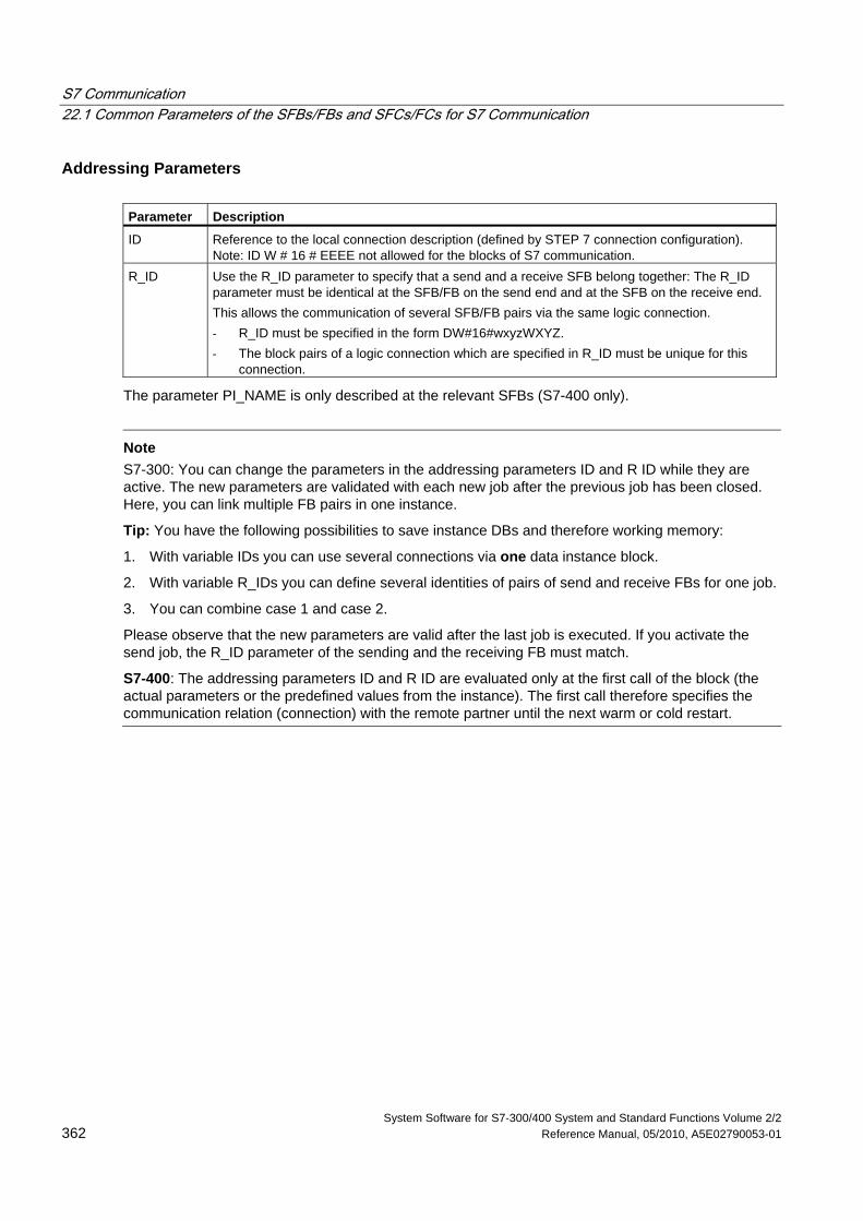
S7 Communication 22.1 Common Parameters of the SFBs/FBs and SFCs/FCs for S7 Communication
System Software for S7-300/400 System and Standard Functions Volume 2/2 362 Reference Manual, 05/2010, A5E02790053-01
Addressing Parameters Parameter Description
ID Reference to the local connection description (defined by STEP 7 connection configuration). Note: ID W # 16 # EEEE not allowed for the blocks of S7 communication.
R_ID Use the R_ID parameter to specify that a send and a receive SFB belong together: The R_ID parameter must be identical at the SFB/FB on the send end and at the SFB on the receive end. This allows the communication of several SFB/FB pairs via the same logic connection. - R_ID must be specified in the form DW#16#wxyzWXYZ. - The block pairs of a logic connection which are specified in R_ID must be unique for this
connection.
The parameter PI_NAME is only described at the relevant SFBs (S7-400 only).
Note
S7-300: You can change the parameters in the addressing parameters ID and R ID while they are active. The new parameters are validated with each new job after the previous job has been closed. Here, you can link multiple FB pairs in one instance.
Tip: You have the following possibilities to save instance DBs and therefore working memory:
1. With variable IDs you can use several connections via one data instance block.
2. With variable R_IDs you can define several identities of pairs of send and receive FBs for one job.
3. You can combine case 1 and case 2.
Please observe that the new parameters are valid after the last job is executed. If you activate the send job, the R_ID parameter of the sending and the receiving FB must match.
S7-400: The addressing parameters ID and R ID are evaluated only at the first call of the block (the actual parameters or the predefined values from the instance). The first call therefore specifies the communication relation (connection) with the remote partner until the next warm or cold restart.
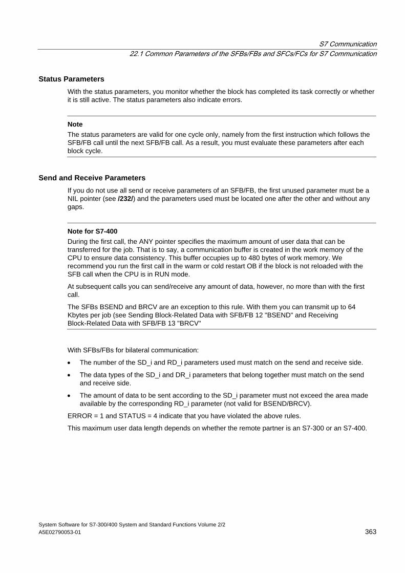
S7 Communication 22.1 Common Parameters of the SFBs/FBs and SFCs/FCs for S7 Communication
System Software for S7-300/400 System and Standard Functions Volume 2/2 A5E02790053-01 363
Status Parameters With the status parameters, you monitor whether the block has completed its task correctly or whether it is still active. The status parameters also indicate errors.
Note
The status parameters are valid for one cycle only, namely from the first instruction which follows the SFB/FB call until the next SFB/FB call. As a result, you must evaluate these parameters after each block cycle.
Send and Receive Parameters If you do not use all send or receive parameters of an SFB/FB, the first unused parameter must be a NIL pointer (see /232/) and the parameters used must be located one after the other and without any gaps.
Note for S7-400
During the first call, the ANY pointer specifies the maximum amount of user data that can be transferred for the job. That is to say, a communication buffer is created in the work memory of the CPU to ensure data consistency. This buffer occupies up to 480 bytes of work memory. We recommend you run the first call in the warm or cold restart OB if the block is not reloaded with the SFB call when the CPU is in RUN mode.
At subsequent calls you can send/receive any amount of data, however, no more than with the first call.
The SFBs BSEND and BRCV are an exception to this rule. With them you can transmit up to 64 Kbytes per job (see Sending Block-Related Data with SFB/FB 12 "BSEND" and Receiving Block-Related Data with SFB/FB 13 "BRCV"
With SFBs/FBs for bilateral communication:
• The number of the SD_i and RD_i parameters used must match on the send and receive side.
• The data types of the SD_i and DR_i parameters that belong together must match on the send and receive side.
• The amount of data to be sent according to the SD_i parameter must not exceed the area made available by the corresponding RD_i parameter (not valid for BSEND/BRCV).
ERROR = 1 and STATUS = 4 indicate that you have violated the above rules.
This maximum user data length depends on whether the remote partner is an S7-300 or an S7-400.
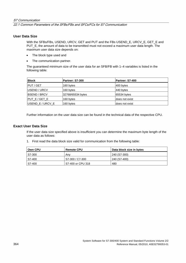
S7 Communication 22.1 Common Parameters of the SFBs/FBs and SFCs/FCs for S7 Communication
System Software for S7-300/400 System and Standard Functions Volume 2/2 364 Reference Manual, 05/2010, A5E02790053-01
User Data Size With the SFBs/FBs, USEND, URCV, GET and PUT and the FBs USEND_E, URCV_E, GET_E and PUT_E, the amount of data to be transmitted must not exceed a maximum user data length. The maximum user data size depends on:
• The block type used and
• The communication partner.
The guaranteed minimum size of the user data for an SFB/FB with 1–4 variables is listed in the following table:
Block Partner: S7-300 Partner: S7-400
PUT / GET 160 bytes 400 bytes USEND / URCV 160 bytes 440 bytes BSEND / BRCV 32768/65534 bytes 65534 bytes PUT_E / GET_E 160 bytes does not exist USEND_E / URCV_E 160 bytes does not exist
Further information on the user data size can be found in the technical data of the respective CPU.
Exact User Data Size If the user data size specified above is insufficient you can determine the maximum byte length of the user data as follows:
1. First read the data block size valid for communication from the following table:
Own CPU Remote CPU Data block size in bytes
S7-300 Any 240 (S7-300) S7-400 S7-300 / C7-300 240 (S7-400) S7-400 S7-400 or CPU 318 480
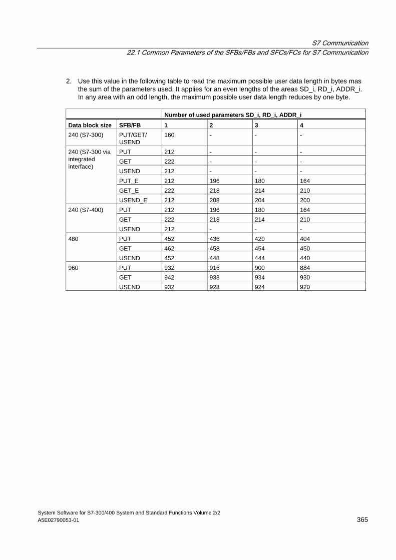
S7 Communication 22.1 Common Parameters of the SFBs/FBs and SFCs/FCs for S7 Communication
System Software for S7-300/400 System and Standard Functions Volume 2/2 A5E02790053-01 365
2. Use this value in the following table to read the maximum possible user data length in bytes mas the sum of the parameters used. It applies for an even lengths of the areas SD_i, RD_i, ADDR_i. In any area with an odd length, the maximum possible user data length reduces by one byte.
Number of used parameters SD_i, RD_i, ADDR_i Data block size SFB/FB 1 2 3 4 240 (S7-300) PUT/GET/
USEND 160 - - -
PUT 212 - - - GET 222 - - - USEND 212 - - - PUT_E 212 196 180 164 GET_E 222 218 214 210
240 (S7-300 via integrated interface)
USEND_E 212 208 204 200 PUT 212 196 180 164 GET 222 218 214 210
240 (S7-400)
USEND 212 - - - PUT 452 436 420 404 GET 462 458 454 450
480
USEND 452 448 444 440 PUT 932 916 900 884 GET 942 938 934 930
960
USEND 932 928 924 920
S7 Communication 22.2 Startup Routine of SFBs for Configured S7 Connections
System Software for S7-300/400 System and Standard Functions Volume 2/2 366 Reference Manual, 05/2010, A5E02790053-01
22.2 Startup Routine of SFBs for Configured S7 Connections
Requirements In the following description for S7-400, it is assumed that:
• The connection descriptions (SDBs) exist on the modules.
• The configured connections have been established.
• The actual parameter for the ID matches the configured connection ID for each SFB.
Warm Restart and Cold Restart During a warm and a cold restart all SFBs are set to the NO_INIT status. The actual parameters stored in the instance DBs are not changed.
Warm Restart and Cold Restart with SFBs for Bilateral Data Exchange In general, the two modules with SFBs for bilateral data exchange do not both go through a warm or cold restart simultaneously. The reaction of the SFB is governed by the rules below:
The receive blocks (SFBs URCV, BRCV) react as follows:
• If the SFB has received a job but has not acknowledged this job at the time of the warm or cold restart, it generates a sequence abort frame (CFB, BRCV) and then immediately branches to the NO_INIT status.
• With SFB BRCV, it is possible that another data segment will be received despite having sent the sequence abort. This will be discarded locally.
• SFB URCV changes to the NO_INIT status immediately.
The send blocks (SFBs USEND, BSEND) react as follows:
• If SFB BSEND has started a job sequence that has not yet been completed, it sends a sequence abort when the warm or cold restart is initiated. It then branches to the NO_INIT status immediately afterwards. An acknowledgement that arrives at a later time is discarded locally.
• If SFB BSEND has already sent or received a sequence abort when the warm or cold restart is requested, it changes immediately to the NO_INIT status.
• In all other cases and whenever the SFB sends only messages (for example, SFB USEND), local processing is aborted and the SFB immediately branches to the NO_INIT status.
S7 Communication 22.2 Startup Routine of SFBs for Configured S7 Connections
System Software for S7-300/400 System and Standard Functions Volume 2/2 A5E02790053-01 367
Warm Restart and Cold Restart with SFBs for Unilateral Data Exchange It is assumed that the server on the communication partner is operational after the connections have been established, in other words that it can process jobs or output messages at any time.
SFBs that send out jobs and expect acknowledgements react to a complete restart as follows:
The current processing is aborted and the CFB branches to the NO_INIT status immediately afterwards. If an acknowledgement for the job sent prior to the warm or cold restart arrives later, it is discarded locally.
A new job may have been sent before the acknowledgement of the earlier job is received.
SFBs that output or receive messages react as follows:
• The current processing is aborted and the CFB branches to the NO_INIT status immediately afterwards.
• With SFB USTATUS, messages that arrive during the NO_INIT and DISABLED statuses are discarded locally.
Reaction to a Hot Restart The SFBs for S7 communication are set to the NO_INIT status only during a warm or cold restart. This means that they react like user function blocks that can be resumed following a hot restart.
Reaction to a Memory Reset A memory reset always causes all connections to be terminated. Since a warm or cold restart is the only possible startup type for the user program after a memory reset, all SFBs for S7 communications (if they still exist) are set to the NO_INIT status and initialized. Partner blocks in a module whose memory was not reset change to the IDLE, ENABLED or DISABLED statuses as a reaction to the connection being terminated.
S7 Communication 22.3 How SFBs React to Problems
System Software for S7-300/400 System and Standard Functions Volume 2/2 368 Reference Manual, 05/2010, A5E02790053-01
22.3 How SFBs React to Problems
The following section describes how SFBs for S7 communication in S7-400 react to problems.
Connection Terminated The connections allocated to the SFB instances are monitored.
If a connection is terminated, the reaction of the SFB depends on its internal status.
If the break down of the connection is detected while the block is in the IDLE or ENABLED status, the SFB reacts as follows:
• It branches to the ERROR status and outputs the error ID "Communication problems" at the ERROR and STATUS output parameters.
• When it is next called, the block returns to its original status and checks the connection again.
A communication SFB that is not in the IDLE or DISABLED statuses reacts as follows:
• It aborts processing, changes to the ERROR status immediately or at the next block call and outputs the error ID "Communication problems" at the ERROR and STATUS output parameters.
• When it is next called, the block changes to the IDLE, DISABLED or ENABLED status. In the IDLE and ENABLED status the connection is checked again.
This procedure will also be executed if the connection has again been set up in the meantime.
Power Down A power down with battery backup followed by a restart causes all established connections to be terminated. The points made above therefore apply to all blocks involved.
If there is a power down with battery backup followed by an automatic warm or cold restart, the points made about terminated connections and warm or cold restarts apply.
In the special case of an automatic warm or cold restart without battery backup, where a memory reset is executed automatically after power returns, the SFBs for S7 communications react as described in the section "Startup Routine of the SFBs For S7 Communications."
Reaction to Operating Mode Changes If the operating mode changes between the STOP, START, RUN, and HOLD statuses, the communication SFB remains in its current status (exception: during a warm or cold restart, it changes to the NO_INIT status). This applies both to SFBs for unilateral as well as SFBs for bilateral communication.
S7 Communication 22.3 How SFBs React to Problems
System Software for S7-300/400 System and Standard Functions Volume 2/2 A5E02790053-01 369
Error Interface to the User Program If an error occurs during the processing of a communication SFB, it always changes to the ERROR status. At the same time the ERROR output parameter is set to 1 and the corresponding error ID is entered in the STATUS output parameter. You can evaluate this error information in your program.
Examples of possible errors:
• Error when collecting send data.
• Error when copying receive data into the receive areas (for example, attempting to access a DB that does not exist).
• The length of the data area sent does not match the length of the receive area specified in the partner SFB.

S7 Communication 22.4 Uncoordinated Sending of Data with SFB 8/FB 8 "USEND"
System Software for S7-300/400 System and Standard Functions Volume 2/2 370 Reference Manual, 05/2010, A5E02790053-01
22.4 Uncoordinated Sending of Data with SFB 8/FB 8 "USEND"
Note
S7-300 CPUs have the two following versions of FB8 "USEND":
• One version in the Standard Library. Use this if the connection to the remote partner is over the PN interface.
• One version in the SIMATIC_NET_CP Library. Use this version if the connection to the remote partner is over a CP.
Description SFB/FB 8 "USEND" sends data to a remote partner SFB/FB of the type "URCV". The send process is carried out without coordination with the SFB/FB partner. This means that the data transfer is carried out without acknowledgement by the partner SFB/FB.
S7-300: The data is sent on a rising edge at REQ. The parameters R_ID, ID and SD_1 are transferred on each rising edge at REQ. After a job has been completed, you can assign new values to the R_ID, ID and SD_1 parameters.
S7-400: The data is sent on a rising edge at control input REQ. The data to be sent is referenced by the parameters SD_1 to SD_4 but not all four send parameters need to be used.
You must, however, make sure that the areas defined by the parameters SD_1 to SD_4/SD_1 and RD_1 to RD_4/RD_1 (at the corresponding partner SFB/FB "URCV") agree in:
• Number
• Length and
• Data type.
The parameter R_ID must be identical at both SFBs.
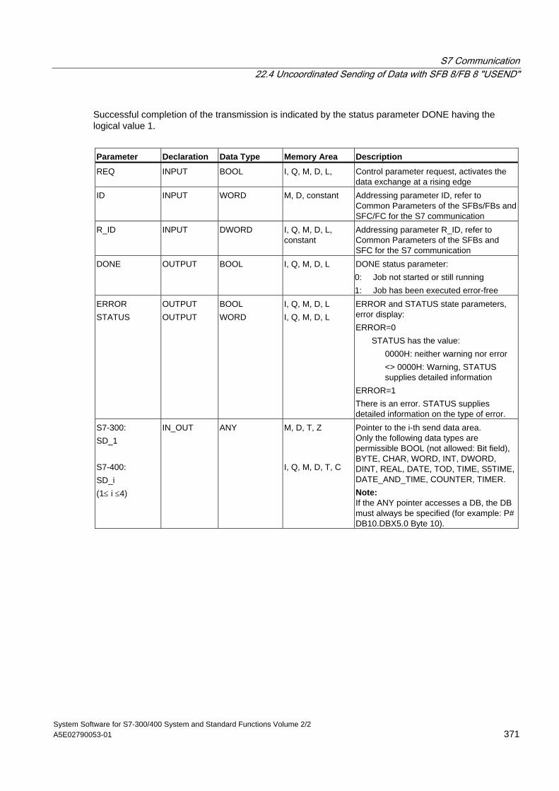
S7 Communication 22.4 Uncoordinated Sending of Data with SFB 8/FB 8 "USEND"
System Software for S7-300/400 System and Standard Functions Volume 2/2 A5E02790053-01 371
Successful completion of the transmission is indicated by the status parameter DONE having the logical value 1.
Parameter Declaration Data Type Memory Area Description
REQ INPUT BOOL I, Q, M, D, L, Control parameter request, activates the data exchange at a rising edge
ID INPUT WORD M, D, constant Addressing parameter ID, refer to Common Parameters of the SFBs/FBs and SFC/FC for the S7 communication
R_ID INPUT DWORD I, Q, M, D, L, constant
Addressing parameter R_ID, refer to Common Parameters of the SFBs and SFC for the S7 communication
DONE OUTPUT BOOL I, Q, M, D, L DONE status parameter: 0: Job not started or still running 1: Job has been executed error-free
ERROR STATUS
OUTPUT OUTPUT
BOOL WORD
I, Q, M, D, L I, Q, M, D, L
ERROR and STATUS state parameters, error display: ERROR=0
STATUS has the value: 0000H: neither warning nor error
<> 0000H: Warning, STATUS supplies detailed information
ERROR=1 There is an error. STATUS supplies detailed information on the type of error.
S7-300: SD_1 S7-400: SD_i (1≤ i ≤4)
IN_OUT ANY M, D, T, Z I, Q, M, D, T, C
Pointer to the i-th send data area. Only the following data types are permissible BOOL (not allowed: Bit field), BYTE, CHAR, WORD, INT, DWORD, DINT, REAL, DATE, TOD, TIME, S5TIME, DATE_AND_TIME, COUNTER, TIMER. Note: If the ANY pointer accesses a DB, the DB must always be specified (for example: P# DB10.DBX5.0 Byte 10).
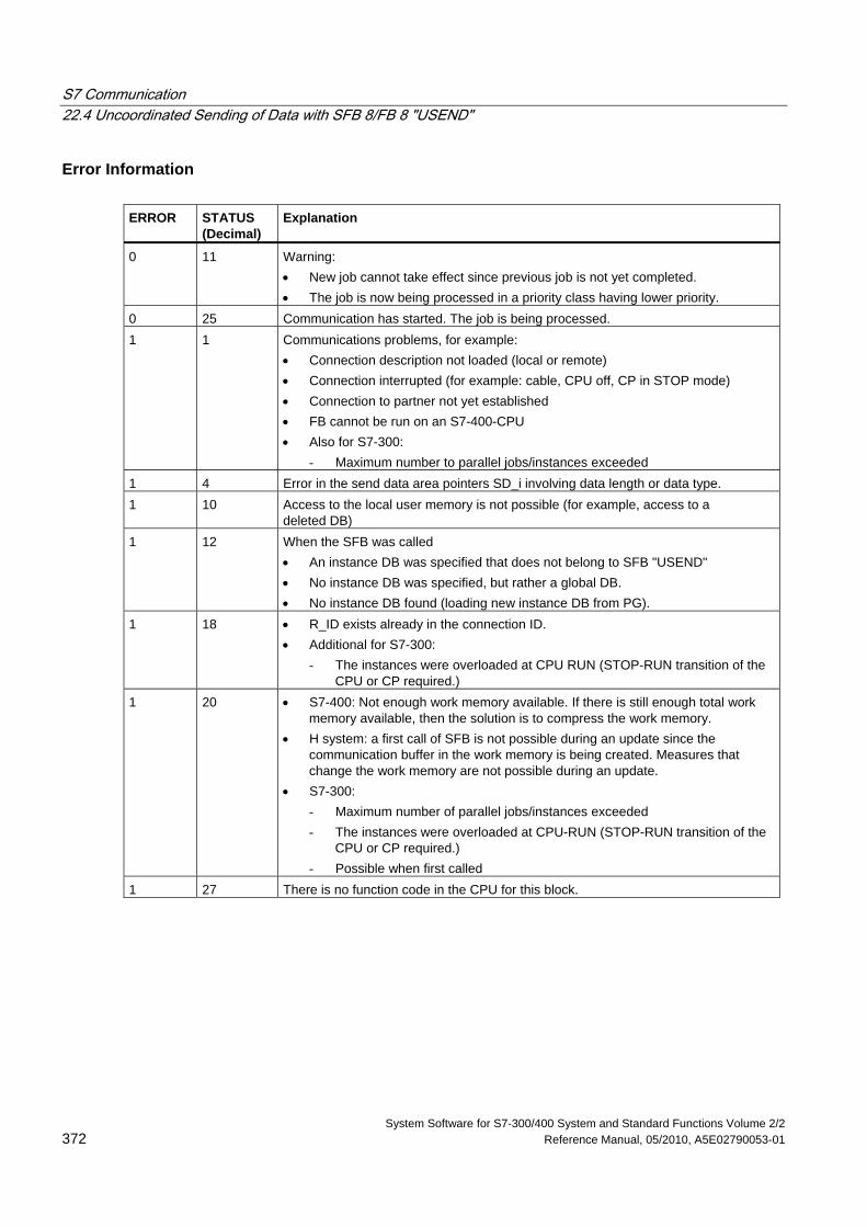
S7 Communication 22.4 Uncoordinated Sending of Data with SFB 8/FB 8 "USEND"
System Software for S7-300/400 System and Standard Functions Volume 2/2 372 Reference Manual, 05/2010, A5E02790053-01
Error Information ERROR
STATUS (Decimal)
Explanation
0 11 Warning: • New job cannot take effect since previous job is not yet completed. • The job is now being processed in a priority class having lower priority.
0 25 Communication has started. The job is being processed. 1 1 Communications problems, for example:
• Connection description not loaded (local or remote) • Connection interrupted (for example: cable, CPU off, CP in STOP mode) • Connection to partner not yet established • FB cannot be run on an S7-400-CPU • Also for S7-300:
- Maximum number to parallel jobs/instances exceeded 1 4 Error in the send data area pointers SD_i involving data length or data type. 1 10 Access to the local user memory is not possible (for example, access to a
deleted DB) 1 12 When the SFB was called
• An instance DB was specified that does not belong to SFB "USEND" • No instance DB was specified, but rather a global DB. • No instance DB found (loading new instance DB from PG).
1 18 • R_ID exists already in the connection ID. • Additional for S7-300:
- The instances were overloaded at CPU RUN (STOP-RUN transition of the CPU or CP required.)
1 20 • S7-400: Not enough work memory available. If there is still enough total work memory available, then the solution is to compress the work memory.
• H system: a first call of SFB is not possible during an update since the communication buffer in the work memory is being created. Measures that change the work memory are not possible during an update.
• S7-300: - Maximum number of parallel jobs/instances exceeded - The instances were overloaded at CPU-RUN (STOP-RUN transition of the
CPU or CP required.) - Possible when first called
1 27 There is no function code in the CPU for this block.
S7 Communication 22.4 Uncoordinated Sending of Data with SFB 8/FB 8 "USEND"
System Software for S7-300/400 System and Standard Functions Volume 2/2 A5E02790053-01 373
Data Consistency S7-300: To ensure data consistency, you can only write to the send area SD_1 again after the current send operation is complete. This is the case when the value of the status parameter DONE changes to 1.
S7-400 and S7-300 via an integrated interface: When a send operation is activated (rising edge at REQ) the data to be sent from the send area SD_i are copied from the user program. After the block call, you can write to these areas without corrupting the current send data.
Note
The send operation is only complete when the DONE status parameter has the value 1.
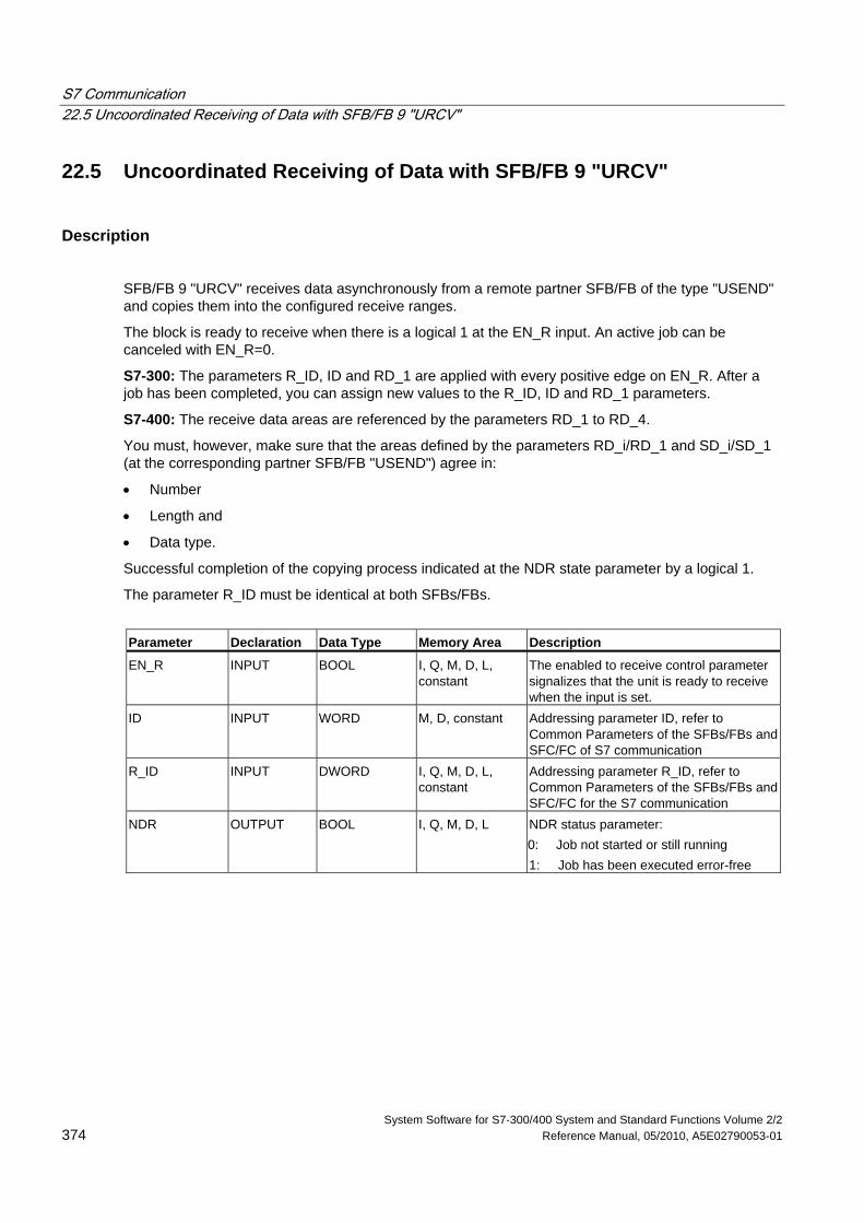
S7 Communication 22.5 Uncoordinated Receiving of Data with SFB/FB 9 "URCV"
System Software for S7-300/400 System and Standard Functions Volume 2/2 374 Reference Manual, 05/2010, A5E02790053-01
22.5 Uncoordinated Receiving of Data with SFB/FB 9 "URCV"
Description
SFB/FB 9 "URCV" receives data asynchronously from a remote partner SFB/FB of the type "USEND" and copies them into the configured receive ranges.
The block is ready to receive when there is a logical 1 at the EN_R input. An active job can be canceled with EN_R=0.
S7-300: The parameters R_ID, ID and RD_1 are applied with every positive edge on EN_R. After a job has been completed, you can assign new values to the R_ID, ID and RD_1 parameters.
S7-400: The receive data areas are referenced by the parameters RD_1 to RD_4.
You must, however, make sure that the areas defined by the parameters RD_i/RD_1 and SD_i/SD_1 (at the corresponding partner SFB/FB "USEND") agree in:
• Number
• Length and
• Data type.
Successful completion of the copying process indicated at the NDR state parameter by a logical 1.
The parameter R_ID must be identical at both SFBs/FBs.
Parameter Declaration Data Type Memory Area Description
EN_R INPUT BOOL I, Q, M, D, L, constant
The enabled to receive control parameter signalizes that the unit is ready to receive when the input is set.
ID INPUT WORD M, D, constant Addressing parameter ID, refer to Common Parameters of the SFBs/FBs and SFC/FC of S7 communication
R_ID INPUT DWORD I, Q, M, D, L, constant
Addressing parameter R_ID, refer to Common Parameters of the SFBs/FBs and SFC/FC for the S7 communication
NDR OUTPUT BOOL I, Q, M, D, L NDR status parameter: 0: Job not started or still running 1: Job has been executed error-free
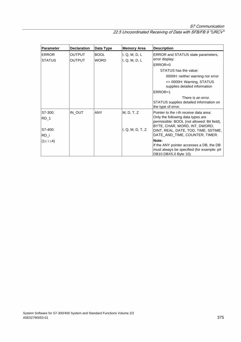
S7 Communication 22.5 Uncoordinated Receiving of Data with SFB/FB 9 "URCV"
System Software for S7-300/400 System and Standard Functions Volume 2/2 A5E02790053-01 375
Parameter Declaration Data Type Memory Area Description
ERROR STATUS
OUTPUT OUTPUT
BOOL WORD
I, Q, M, D, L I, Q, M, D, L
ERROR and STATUS state parameters, error display: ERROR=0
STATUS has the value: 0000H: neither warning nor error
<> 0000H: Warning, STATUS supplies detailed information
ERROR=1 There is an error. STATUS supplies detailed information on the type of error.
S7-300: RD_1 S7-400: RD_i (1≤ i ≤4)
IN_OUT ANY M, D, T, Z I, Q, M, D, T, Z
Pointer to the i-th receive data area: Only the following data types are permissible: BOOL (not allowed: Bit field), BYTE, CHAR, WORD, INT, DWORD, DINT, REAL, DATE, TOD, TIME, S5TIME, DATE_AND_TIME, COUNTER, TIMER. Note: If the ANY pointer accesses a DB, the DB must always be specified (for example: p# DB10.DBX5.0 Byte 10).
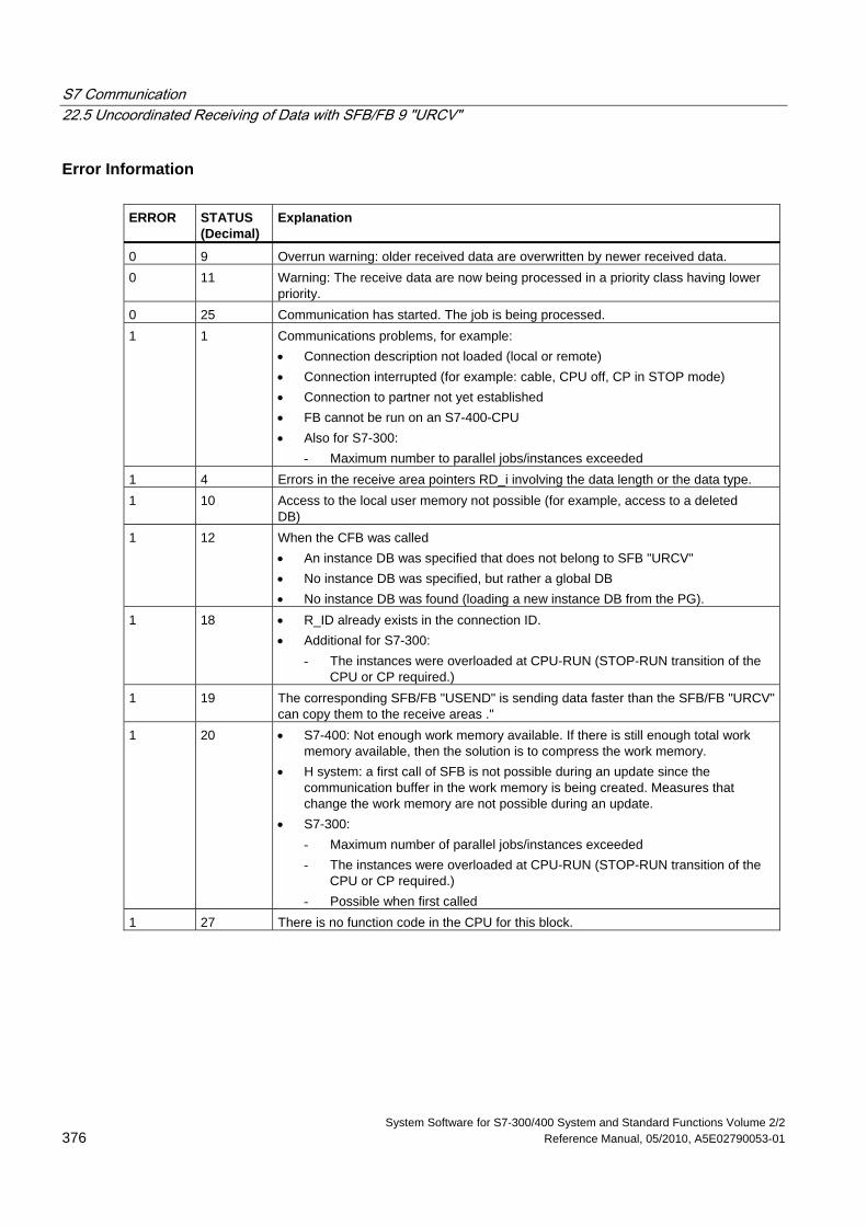
S7 Communication 22.5 Uncoordinated Receiving of Data with SFB/FB 9 "URCV"
System Software for S7-300/400 System and Standard Functions Volume 2/2 376 Reference Manual, 05/2010, A5E02790053-01
Error Information ERROR
STATUS (Decimal)
Explanation
0 9 Overrun warning: older received data are overwritten by newer received data. 0 11 Warning: The receive data are now being processed in a priority class having lower
priority. 0 25 Communication has started. The job is being processed. 1 1 Communications problems, for example:
• Connection description not loaded (local or remote) • Connection interrupted (for example: cable, CPU off, CP in STOP mode) • Connection to partner not yet established • FB cannot be run on an S7-400-CPU • Also for S7-300:
- Maximum number to parallel jobs/instances exceeded 1 4 Errors in the receive area pointers RD_i involving the data length or the data type. 1 10 Access to the local user memory not possible (for example, access to a deleted
DB) 1 12 When the CFB was called
• An instance DB was specified that does not belong to SFB "URCV" • No instance DB was specified, but rather a global DB • No instance DB was found (loading a new instance DB from the PG).
1 18 • R_ID already exists in the connection ID. • Additional for S7-300:
- The instances were overloaded at CPU-RUN (STOP-RUN transition of the CPU or CP required.)
1 19 The corresponding SFB/FB "USEND" is sending data faster than the SFB/FB "URCV" can copy them to the receive areas ."
1 20 • S7-400: Not enough work memory available. If there is still enough total work memory available, then the solution is to compress the work memory.
• H system: a first call of SFB is not possible during an update since the communication buffer in the work memory is being created. Measures that change the work memory are not possible during an update.
• S7-300: - Maximum number of parallel jobs/instances exceeded - The instances were overloaded at CPU-RUN (STOP-RUN transition of the
CPU or CP required.) - Possible when first called
1 27 There is no function code in the CPU for this block.
S7 Communication 22.5 Uncoordinated Receiving of Data with SFB/FB 9 "URCV"
System Software for S7-300/400 System and Standard Functions Volume 2/2 A5E02790053-01 377
Data Consistency The data are received consistently if you remember the following points:
• S7-300: After the status parameter NDR has changed to the value 1, you must immediately call FB 9 "URCV" again with the value 0 at EN_R. This ensures that the receive area is not overwritten before you have evaluated it.
• Evaluate the receive area (RD_1) completely before you call the block with the value 1 at control input EN_R).
S7-400: After the status parameter NDR has changed to the value 1, there are new receive data in your receive areas (RD_i). A new block call may cause these data to be overwritten with new receive data. If you want to prevent this, you must call SFB 9 "URCV" (such as with cyclic block processing) with the value 0 at EN_R until you have finished processing the receive data.
S7 Communication 22.6 Sending Segmented Data with SFB/FB 12 "BSEND"
System Software for S7-300/400 System and Standard Functions Volume 2/2 378 Reference Manual, 05/2010, A5E02790053-01
22.6 Sending Segmented Data with SFB/FB 12 "BSEND"
Description SFB/FB 12 "BSEND" sends data to a remote partner SFB/FB of the type "BRCV". With this type of data transfer, more data can be transported between the communications partners than is possible with all other communication SFBs/FBs for configured S7 connections:
• 32768 bytes for S7-300 via SIMATIC-Net CPs
• 65534 bytes for S7-400 and S7-300 via an integrated interface
The data area to be transmitted is segmented. Each segment is sent individually to the partner. The last segment is acknowledged by the partner as it is received, independently of the calling up of the corresponding SFB/FB "BRCV".
S7-300: The send job is activated on a rising edge at REQ. The parameters R_ID, ID, SD_1 and LEN are transferred on each positive edge at REQ. After a job has been completed, you can assign new values to the R_ID, ID, SD_1 and LEN parameters. For the transmission of segmented data the block must be called periodically in the user program.
The start address and the maximum length of the data to be sent are specified by SD_1. You can determine the job-specific length of the data field with LEN.
S7-400 and S7-300 via an integrated interface: The send job is activated after calling the block and when there is a rising edge at the control input REQ. Sending the data from the user memory is carried out asynchronously to the processing of the user program.
The start address and the maximum length of the data to be sent are specified by SD_1. You can determine the job-specific length of the data field with LEN. In this case, LEN replaces the length section of SD_1.
The parameter R_ID must be identical at the two corresponding SFBs/FBs.
If there is a rising edge at control input R, the current data transfer is canceled.
Successful completion of the transfer is indicated by the status parameter DONE having the value 1.
A new send job cannot be processed until the previous send process has been completed if the status parameter DONE or ERROR have the value 1.
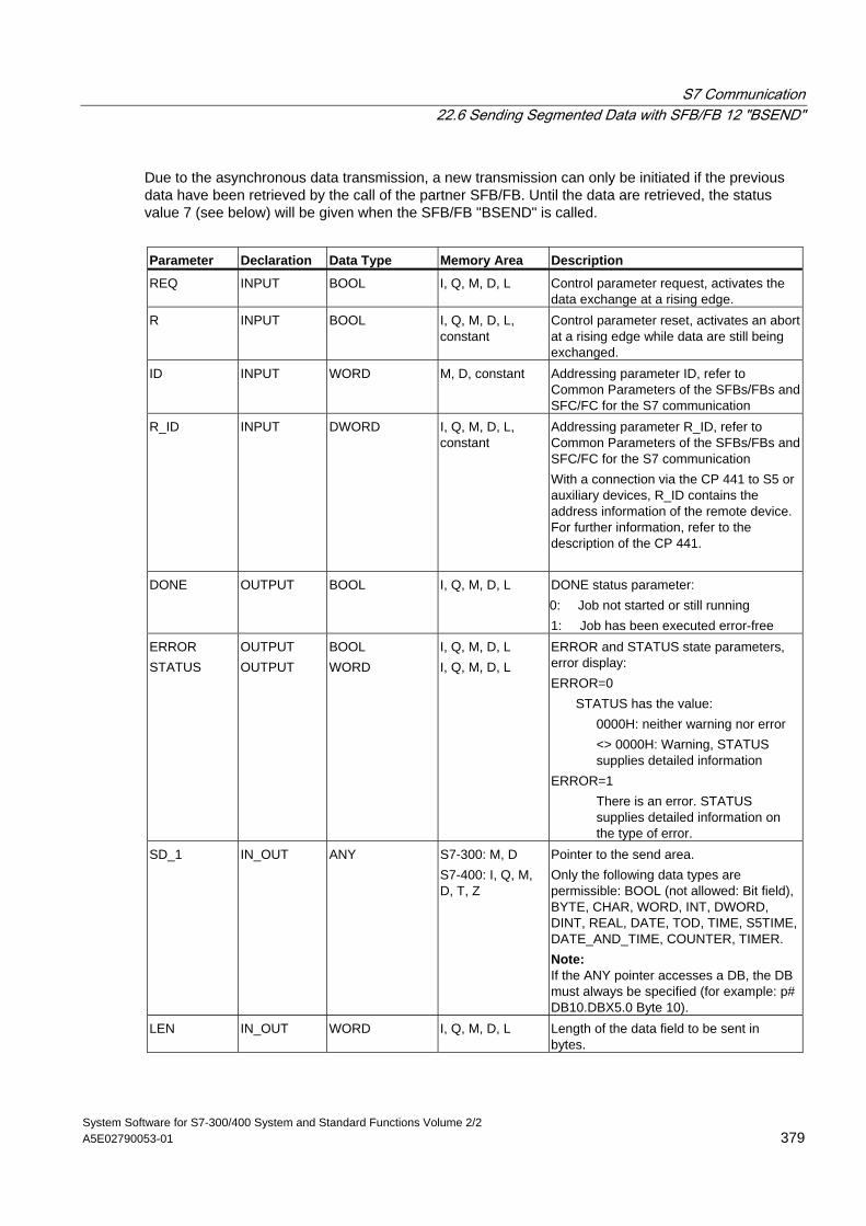
S7 Communication 22.6 Sending Segmented Data with SFB/FB 12 "BSEND"
System Software for S7-300/400 System and Standard Functions Volume 2/2 A5E02790053-01 379
Due to the asynchronous data transmission, a new transmission can only be initiated if the previous data have been retrieved by the call of the partner SFB/FB. Until the data are retrieved, the status value 7 (see below) will be given when the SFB/FB "BSEND" is called.
Parameter Declaration Data Type Memory Area Description
REQ INPUT BOOL I, Q, M, D, L Control parameter request, activates the data exchange at a rising edge.
R INPUT BOOL I, Q, M, D, L, constant
Control parameter reset, activates an abort at a rising edge while data are still being exchanged.
ID INPUT WORD M, D, constant Addressing parameter ID, refer to Common Parameters of the SFBs/FBs and SFC/FC for the S7 communication
R_ID INPUT DWORD I, Q, M, D, L, constant
Addressing parameter R_ID, refer to Common Parameters of the SFBs/FBs and SFC/FC for the S7 communication With a connection via the CP 441 to S5 or auxiliary devices, R_ID contains the address information of the remote device. For further information, refer to the description of the CP 441.
DONE OUTPUT BOOL I, Q, M, D, L DONE status parameter: 0: Job not started or still running 1: Job has been executed error-free
ERROR STATUS
OUTPUT OUTPUT
BOOL WORD
I, Q, M, D, L I, Q, M, D, L
ERROR and STATUS state parameters, error display: ERROR=0
STATUS has the value: 0000H: neither warning nor error
<> 0000H: Warning, STATUS supplies detailed information
ERROR=1 There is an error. STATUS supplies detailed information on the type of error.
SD_1 IN_OUT ANY S7-300: M, D S7-400: I, Q, M, D, T, Z
Pointer to the send area. Only the following data types are permissible: BOOL (not allowed: Bit field), BYTE, CHAR, WORD, INT, DWORD, DINT, REAL, DATE, TOD, TIME, S5TIME, DATE_AND_TIME, COUNTER, TIMER. Note: If the ANY pointer accesses a DB, the DB must always be specified (for example: p# DB10.DBX5.0 Byte 10).
LEN IN_OUT WORD I, Q, M, D, L Length of the data field to be sent in bytes.
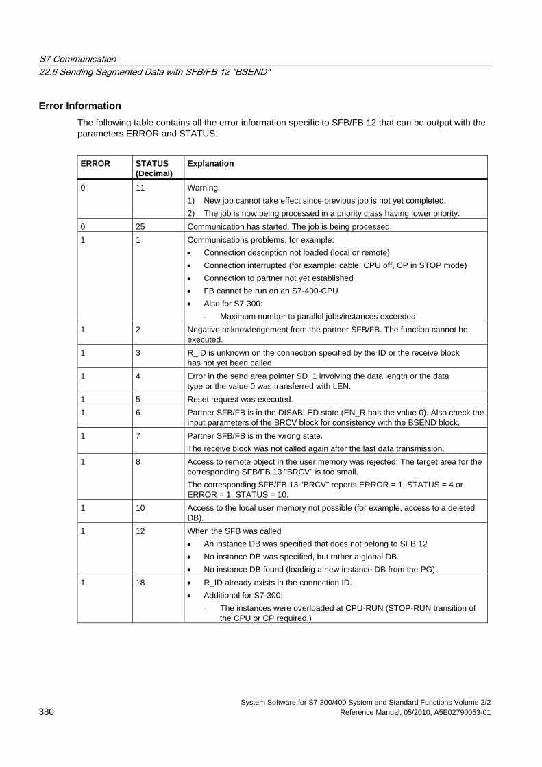
S7 Communication 22.6 Sending Segmented Data with SFB/FB 12 "BSEND"
System Software for S7-300/400 System and Standard Functions Volume 2/2 380 Reference Manual, 05/2010, A5E02790053-01
Error Information The following table contains all the error information specific to SFB/FB 12 that can be output with the parameters ERROR and STATUS.
ERROR
STATUS (Decimal)
Explanation
0 11 Warning: 1) New job cannot take effect since previous job is not yet completed. 2) The job is now being processed in a priority class having lower priority.
0 25 Communication has started. The job is being processed. 1 1 Communications problems, for example:
• Connection description not loaded (local or remote) • Connection interrupted (for example: cable, CPU off, CP in STOP mode) • Connection to partner not yet established • FB cannot be run on an S7-400-CPU • Also for S7-300:
- Maximum number to parallel jobs/instances exceeded 1 2 Negative acknowledgement from the partner SFB/FB. The function cannot be
executed. 1 3 R_ID is unknown on the connection specified by the ID or the receive block
has not yet been called. 1 4 Error in the send area pointer SD_1 involving the data length or the data
type or the value 0 was transferred with LEN. 1 5 Reset request was executed. 1 6 Partner SFB/FB is in the DISABLED state (EN_R has the value 0). Also check the
input parameters of the BRCV block for consistency with the BSEND block. 1 7 Partner SFB/FB is in the wrong state.
The receive block was not called again after the last data transmission. 1 8 Access to remote object in the user memory was rejected: The target area for the
corresponding SFB/FB 13 "BRCV" is too small. The corresponding SFB/FB 13 "BRCV" reports ERROR = 1, STATUS = 4 or ERROR = 1, STATUS = 10.
1 10 Access to the local user memory not possible (for example, access to a deleted DB).
1 12 When the SFB was called • An instance DB was specified that does not belong to SFB 12 • No instance DB was specified, but rather a global DB. • No instance DB found (loading a new instance DB from the PG).
1 18 • R_ID already exists in the connection ID. • Additional for S7-300:
- The instances were overloaded at CPU-RUN (STOP-RUN transition of the CPU or CP required.)
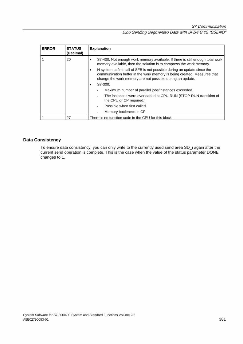
S7 Communication 22.6 Sending Segmented Data with SFB/FB 12 "BSEND"
System Software for S7-300/400 System and Standard Functions Volume 2/2 A5E02790053-01 381
ERROR
STATUS (Decimal)
Explanation
1 20 • S7-400: Not enough work memory available. If there is still enough total work memory available, then the solution is to compress the work memory.
• H system: a first call of SFB is not possible during an update since the communication buffer in the work memory is being created. Measures that change the work memory are not possible during an update.
• S7-300: - Maximum number of parallel jobs/instances exceeded - The instances were overloaded at CPU-RUN (STOP-RUN transition of
the CPU or CP required.) - Possible when first called - Memory bottleneck in CP
1 27 There is no function code in the CPU for this block.
Data Consistency To ensure data consistency, you can only write to the currently used send area SD_i again after the current send operation is complete. This is the case when the value of the status parameter DONE changes to 1.
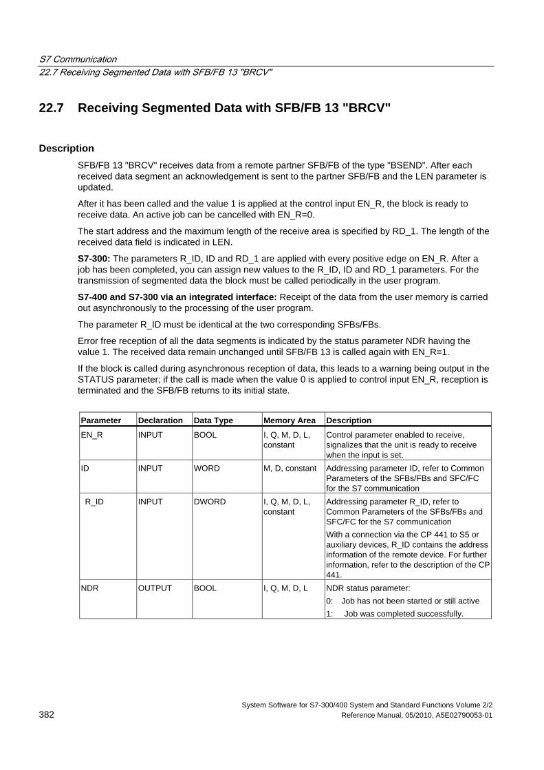
S7 Communication 22.7 Receiving Segmented Data with SFB/FB 13 "BRCV"
System Software for S7-300/400 System and Standard Functions Volume 2/2 382 Reference Manual, 05/2010, A5E02790053-01
22.7 Receiving Segmented Data with SFB/FB 13 "BRCV"
Description SFB/FB 13 "BRCV" receives data from a remote partner SFB/FB of the type "BSEND". After each received data segment an acknowledgement is sent to the partner SFB/FB and the LEN parameter is updated.
After it has been called and the value 1 is applied at the control input EN_R, the block is ready to receive data. An active job can be cancelled with EN_R=0.
The start address and the maximum length of the receive area is specified by RD_1. The length of the received data field is indicated in LEN.
S7-300: The parameters R_ID, ID and RD_1 are applied with every positive edge on EN_R. After a job has been completed, you can assign new values to the R_ID, ID and RD_1 parameters. For the transmission of segmented data the block must be called periodically in the user program.
S7-400 and S7-300 via an integrated interface: Receipt of the data from the user memory is carried out asynchronously to the processing of the user program.
The parameter R_ID must be identical at the two corresponding SFBs/FBs.
Error free reception of all the data segments is indicated by the status parameter NDR having the value 1. The received data remain unchanged until SFB/FB 13 is called again with EN_R=1.
If the block is called during asynchronous reception of data, this leads to a warning being output in the STATUS parameter; if the call is made when the value 0 is applied to control input EN_R, reception is terminated and the SFB/FB returns to its initial state.
Parameter Declaration Data Type Memory Area Description
EN_R INPUT BOOL I, Q, M, D, L, constant
Control parameter enabled to receive, signalizes that the unit is ready to receive when the input is set.
ID INPUT WORD M, D, constant Addressing parameter ID, refer to Common Parameters of the SFBs/FBs and SFC/FC for the S7 communication
R_ID INPUT DWORD I, Q, M, D, L, constant
Addressing parameter R_ID, refer to Common Parameters of the SFBs/FBs and SFC/FC for the S7 communication With a connection via the CP 441 to S5 or auxiliary devices, R_ID contains the address information of the remote device. For further information, refer to the description of the CP 441.
NDR OUTPUT BOOL I, Q, M, D, L NDR status parameter: 0: Job has not been started or still active 1: Job was completed successfully.
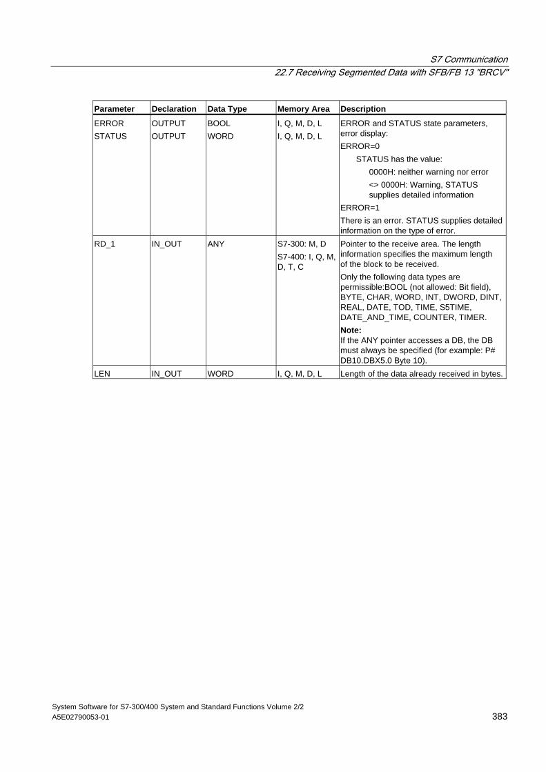
S7 Communication 22.7 Receiving Segmented Data with SFB/FB 13 "BRCV"
System Software for S7-300/400 System and Standard Functions Volume 2/2 A5E02790053-01 383
Parameter Declaration Data Type Memory Area Description
ERROR STATUS
OUTPUT OUTPUT
BOOL WORD
I, Q, M, D, L I, Q, M, D, L
ERROR and STATUS state parameters, error display: ERROR=0
STATUS has the value: 0000H: neither warning nor error
<> 0000H: Warning, STATUS supplies detailed information
ERROR=1 There is an error. STATUS supplies detailed information on the type of error.
RD_1 IN_OUT ANY S7-300: M, D S7-400: I, Q, M, D, T, C
Pointer to the receive area. The length information specifies the maximum length of the block to be received. Only the following data types are permissible:BOOL (not allowed: Bit field), BYTE, CHAR, WORD, INT, DWORD, DINT, REAL, DATE, TOD, TIME, S5TIME, DATE_AND_TIME, COUNTER, TIMER. Note: If the ANY pointer accesses a DB, the DB must always be specified (for example: P# DB10.DBX5.0 Byte 10).
LEN IN_OUT WORD I, Q, M, D, L Length of the data already received in bytes.
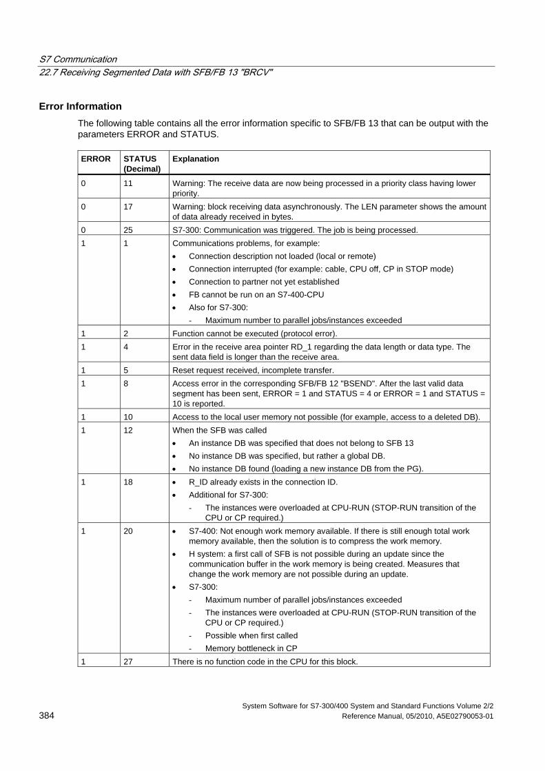
S7 Communication 22.7 Receiving Segmented Data with SFB/FB 13 "BRCV"
System Software for S7-300/400 System and Standard Functions Volume 2/2 384 Reference Manual, 05/2010, A5E02790053-01
Error Information The following table contains all the error information specific to SFB/FB 13 that can be output with the parameters ERROR and STATUS. ERROR
STATUS (Decimal)
Explanation
0 11 Warning: The receive data are now being processed in a priority class having lower priority.
0 17 Warning: block receiving data asynchronously. The LEN parameter shows the amount of data already received in bytes.
0 25 S7-300: Communication was triggered. The job is being processed. 1 1 Communications problems, for example:
• Connection description not loaded (local or remote) • Connection interrupted (for example: cable, CPU off, CP in STOP mode) • Connection to partner not yet established • FB cannot be run on an S7-400-CPU • Also for S7-300:
- Maximum number to parallel jobs/instances exceeded 1 2 Function cannot be executed (protocol error). 1 4 Error in the receive area pointer RD_1 regarding the data length or data type. The
sent data field is longer than the receive area. 1 5 Reset request received, incomplete transfer. 1 8 Access error in the corresponding SFB/FB 12 "BSEND". After the last valid data
segment has been sent, ERROR = 1 and STATUS = 4 or ERROR = 1 and STATUS = 10 is reported.
1 10 Access to the local user memory not possible (for example, access to a deleted DB). 1 12 When the SFB was called
• An instance DB was specified that does not belong to SFB 13 • No instance DB was specified, but rather a global DB. • No instance DB found (loading a new instance DB from the PG).
1 18 • R_ID already exists in the connection ID. • Additional for S7-300:
- The instances were overloaded at CPU-RUN (STOP-RUN transition of the CPU or CP required.)
1 20 • S7-400: Not enough work memory available. If there is still enough total work memory available, then the solution is to compress the work memory.
• H system: a first call of SFB is not possible during an update since the communication buffer in the work memory is being created. Measures that change the work memory are not possible during an update.
• S7-300: - Maximum number of parallel jobs/instances exceeded - The instances were overloaded at CPU-RUN (STOP-RUN transition of the
CPU or CP required.) - Possible when first called - Memory bottleneck in CP
1 27 There is no function code in the CPU for this block.
S7 Communication 22.7 Receiving Segmented Data with SFB/FB 13 "BRCV"
System Software for S7-300/400 System and Standard Functions Volume 2/2 A5E02790053-01 385
Data Consistency The data are received consistently if you remember the following point:
• Evaluate the last used receive areas (RD_1) completely before you call the block again with the value 1 at control input EN_R).
Special Case for Receiving Data (S7-400 only) If a receiving CPU with a BRCV block ready to accept data (that is, a call with EN_R = 1 has already been made) goes into STOP mode before the corresponding send block has sent the first data segment for the job, the following will occur:
• The data in the first job after the receiving CPU has gone into STOP mode are fully entered in the receive area.
• The partner SFB "BSEND" receives a positive acknowledgement.
• Any additional BSEND jobs can no longer be accepted by a receiving CPU in STOP mode.
• As long as the CPU remains in STOP mode, both NDR and LEN have the value 0.
To prevent information about the received data from being lost, you must perform a hot restart of the receiving CPU and call SFB 13 "BRCV" with EN_R = 1.
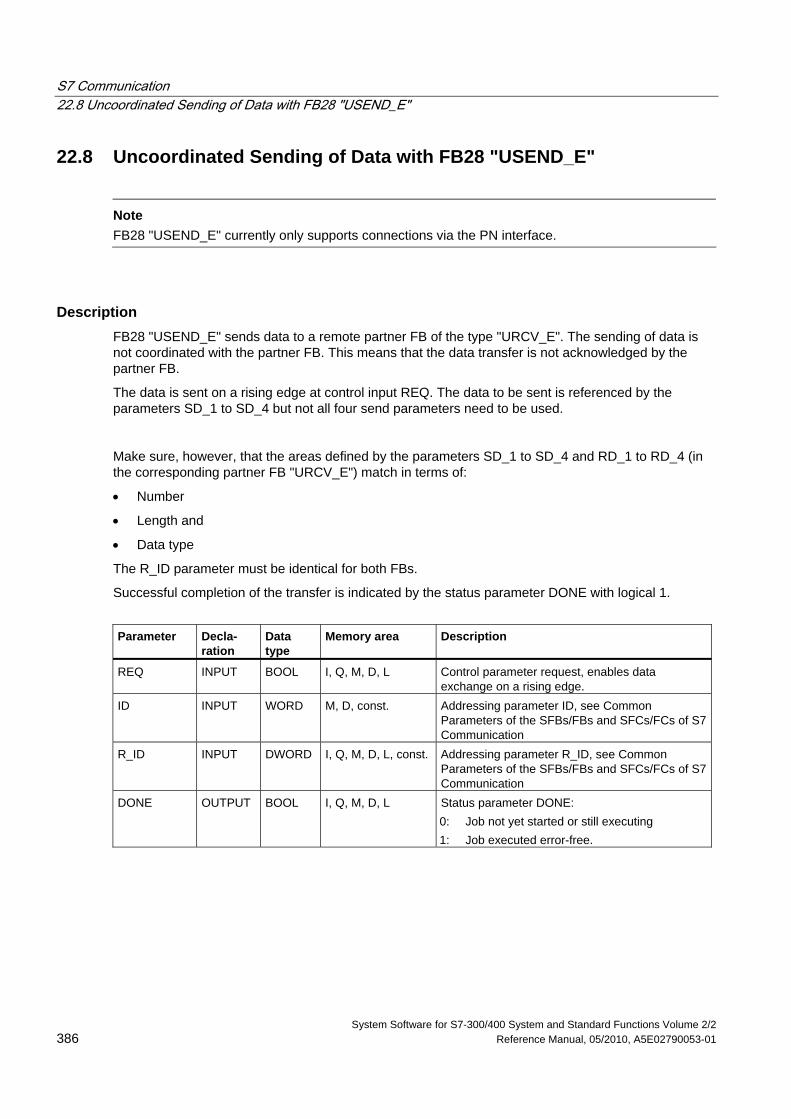
S7 Communication 22.8 Uncoordinated Sending of Data with FB28 "USEND_E"
System Software for S7-300/400 System and Standard Functions Volume 2/2 386 Reference Manual, 05/2010, A5E02790053-01
22.8 Uncoordinated Sending of Data with FB28 "USEND_E"
Note
FB28 "USEND_E" currently only supports connections via the PN interface.
Description FB28 "USEND_E" sends data to a remote partner FB of the type "URCV_E". The sending of data is not coordinated with the partner FB. This means that the data transfer is not acknowledged by the partner FB.
The data is sent on a rising edge at control input REQ. The data to be sent is referenced by the parameters SD_1 to SD_4 but not all four send parameters need to be used.
Make sure, however, that the areas defined by the parameters SD_1 to SD_4 and RD_1 to RD_4 (in the corresponding partner FB "URCV_E") match in terms of:
• Number
• Length and
• Data type
The R_ID parameter must be identical for both FBs.
Successful completion of the transfer is indicated by the status parameter DONE with logical 1.
Parameter Decla-
ration Data type
Memory area Description
REQ INPUT BOOL I, Q, M, D, L Control parameter request, enables data exchange on a rising edge.
ID INPUT WORD M, D, const. Addressing parameter ID, see Common Parameters of the SFBs/FBs and SFCs/FCs of S7 Communication
R_ID INPUT DWORD I, Q, M, D, L, const. Addressing parameter R_ID, see Common Parameters of the SFBs/FBs and SFCs/FCs of S7 Communication
DONE OUTPUT BOOL I, Q, M, D, L Status parameter DONE: 0: Job not yet started or still executing 1: Job executed error-free.
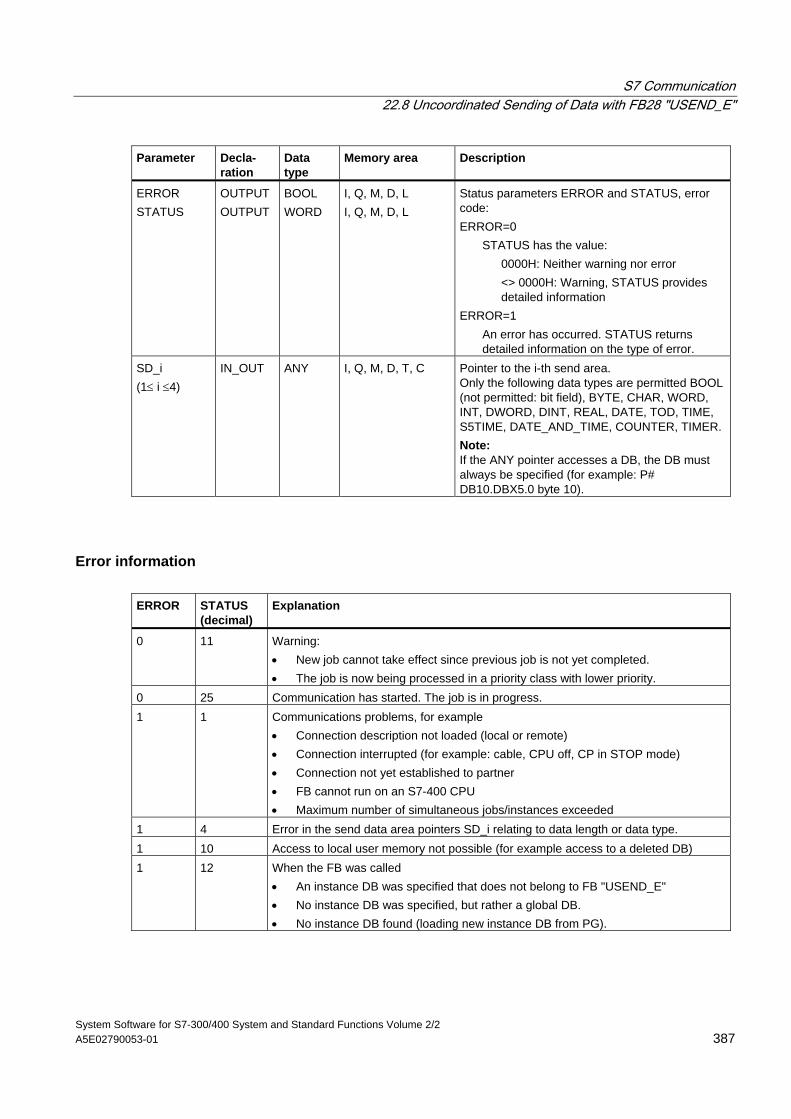
S7 Communication 22.8 Uncoordinated Sending of Data with FB28 "USEND_E"
System Software for S7-300/400 System and Standard Functions Volume 2/2 A5E02790053-01 387
Parameter Decla- ration
Data type
Memory area Description
ERROR STATUS
OUTPUT OUTPUT
BOOL WORD
I, Q, M, D, L I, Q, M, D, L
Status parameters ERROR and STATUS, error code: ERROR=0
STATUS has the value: 0000H: Neither warning nor error
<> 0000H: Warning, STATUS provides detailed information
ERROR=1 An error has occurred. STATUS returns detailed information on the type of error.
SD_i (1≤ i ≤4)
IN_OUT ANY I, Q, M, D, T, C Pointer to the i-th send area. Only the following data types are permitted BOOL (not permitted: bit field), BYTE, CHAR, WORD, INT, DWORD, DINT, REAL, DATE, TOD, TIME, S5TIME, DATE_AND_TIME, COUNTER, TIMER. Note: If the ANY pointer accesses a DB, the DB must always be specified (for example: P# DB10.DBX5.0 byte 10).
Error information ERROR STATUS
(decimal) Explanation
0 11 Warning: • New job cannot take effect since previous job is not yet completed. • The job is now being processed in a priority class with lower priority.
0 25 Communication has started. The job is in progress. 1 1 Communications problems, for example
• Connection description not loaded (local or remote) • Connection interrupted (for example: cable, CPU off, CP in STOP mode) • Connection not yet established to partner • FB cannot run on an S7-400 CPU • Maximum number of simultaneous jobs/instances exceeded
1 4 Error in the send data area pointers SD_i relating to data length or data type. 1 10 Access to local user memory not possible (for example access to a deleted DB) 1 12 When the FB was called
• An instance DB was specified that does not belong to FB "USEND_E" • No instance DB was specified, but rather a global DB. • No instance DB found (loading new instance DB from PG).
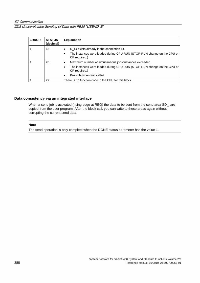
S7 Communication 22.8 Uncoordinated Sending of Data with FB28 "USEND_E"
System Software for S7-300/400 System and Standard Functions Volume 2/2 388 Reference Manual, 05/2010, A5E02790053-01
ERROR STATUS (decimal)
Explanation
1 18 • R_ID exists already in the connection ID. • The instances were loaded during CPU RUN (STOP-RUN change on the CPU or
CP required.) 1 20 • Maximum number of simultaneous jobs/instances exceeded
• The instances were loaded during CPU RUN (STOP-RUN change on the CPU or CP required.)
• Possible when first called 1 27 There is no function code in the CPU for this block.
Data consistency via an integrated interface When a send job is activated (rising edge at REQ) the data to be sent from the send area SD_i are copied from the user program. After the block call, you can write to these areas again without corrupting the current send data.
Note
The send operation is only complete when the DONE status parameter has the value 1.
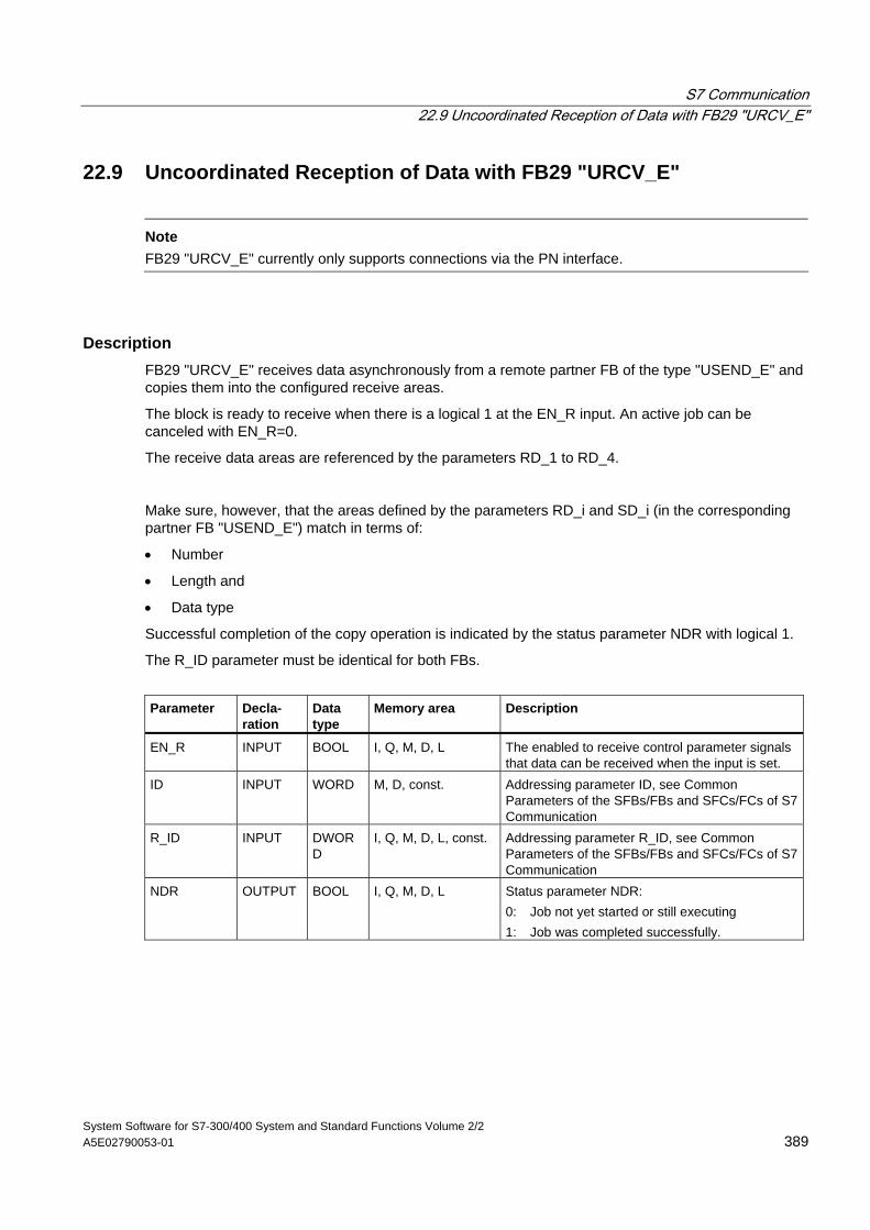
S7 Communication 22.9 Uncoordinated Reception of Data with FB29 "URCV_E"
System Software for S7-300/400 System and Standard Functions Volume 2/2 A5E02790053-01 389
22.9 Uncoordinated Reception of Data with FB29 "URCV_E"
Note
FB29 "URCV_E" currently only supports connections via the PN interface.
Description FB29 "URCV_E" receives data asynchronously from a remote partner FB of the type "USEND_E" and copies them into the configured receive areas.
The block is ready to receive when there is a logical 1 at the EN_R input. An active job can be canceled with EN_R=0.
The receive data areas are referenced by the parameters RD_1 to RD_4.
Make sure, however, that the areas defined by the parameters RD_i and SD_i (in the corresponding partner FB "USEND_E") match in terms of:
• Number
• Length and
• Data type
Successful completion of the copy operation is indicated by the status parameter NDR with logical 1.
The R_ID parameter must be identical for both FBs.
Parameter Decla-
ration Data type
Memory area Description
EN_R INPUT BOOL I, Q, M, D, L The enabled to receive control parameter signals that data can be received when the input is set.
ID INPUT WORD M, D, const. Addressing parameter ID, see Common Parameters of the SFBs/FBs and SFCs/FCs of S7 Communication
R_ID INPUT DWORD
I, Q, M, D, L, const. Addressing parameter R_ID, see Common Parameters of the SFBs/FBs and SFCs/FCs of S7 Communication
NDR OUTPUT BOOL I, Q, M, D, L Status parameter NDR: 0: Job not yet started or still executing 1: Job was completed successfully.
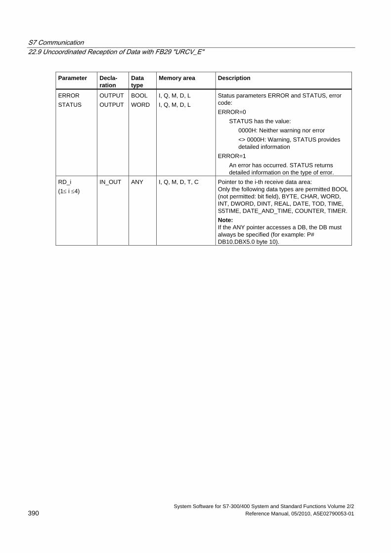
S7 Communication 22.9 Uncoordinated Reception of Data with FB29 "URCV_E"
System Software for S7-300/400 System and Standard Functions Volume 2/2 390 Reference Manual, 05/2010, A5E02790053-01
Parameter Decla- ration
Data type
Memory area Description
ERROR STATUS
OUTPUT OUTPUT
BOOL WORD
I, Q, M, D, L I, Q, M, D, L
Status parameters ERROR and STATUS, error code: ERROR=0
STATUS has the value: 0000H: Neither warning nor error
<> 0000H: Warning, STATUS provides detailed information
ERROR=1 An error has occurred. STATUS returns detailed information on the type of error.
RD_i (1≤ i ≤4)
IN_OUT ANY I, Q, M, D, T, C Pointer to the i-th receive data area: Only the following data types are permitted BOOL (not permitted: bit field), BYTE, CHAR, WORD, INT, DWORD, DINT, REAL, DATE, TOD, TIME, S5TIME, DATE_AND_TIME, COUNTER, TIMER. Note: If the ANY pointer accesses a DB, the DB must always be specified (for example: P# DB10.DBX5.0 byte 10).
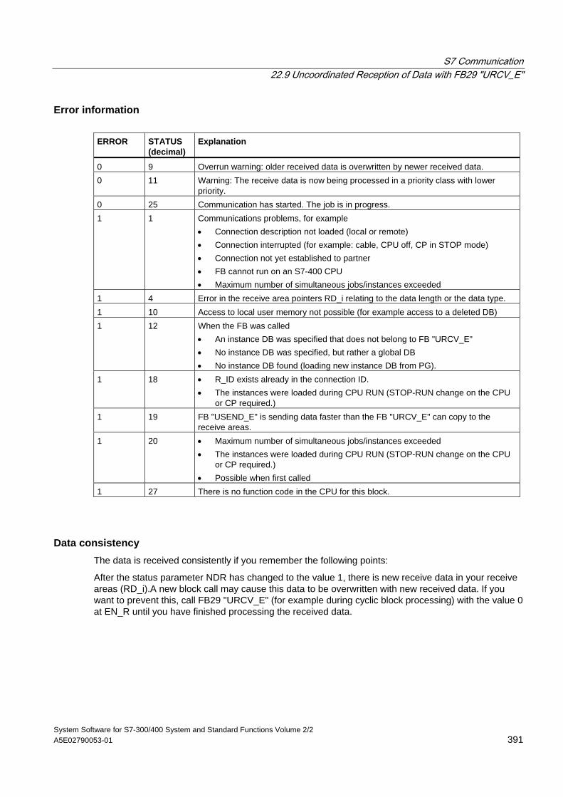
S7 Communication 22.9 Uncoordinated Reception of Data with FB29 "URCV_E"
System Software for S7-300/400 System and Standard Functions Volume 2/2 A5E02790053-01 391
Error information ERROR STATUS
(decimal) Explanation
0 9 Overrun warning: older received data is overwritten by newer received data. 0 11 Warning: The receive data is now being processed in a priority class with lower
priority. 0 25 Communication has started. The job is in progress. 1 1 Communications problems, for example
• Connection description not loaded (local or remote) • Connection interrupted (for example: cable, CPU off, CP in STOP mode) • Connection not yet established to partner • FB cannot run on an S7-400 CPU • Maximum number of simultaneous jobs/instances exceeded
1 4 Error in the receive area pointers RD_i relating to the data length or the data type. 1 10 Access to local user memory not possible (for example access to a deleted DB) 1 12 When the FB was called
• An instance DB was specified that does not belong to FB "URCV_E" • No instance DB was specified, but rather a global DB • No instance DB found (loading new instance DB from PG).
1 18 • R_ID exists already in the connection ID. • The instances were loaded during CPU RUN (STOP-RUN change on the CPU
or CP required.) 1 19 FB "USEND_E" is sending data faster than the FB "URCV_E" can copy to the
receive areas. 1 20 • Maximum number of simultaneous jobs/instances exceeded
• The instances were loaded during CPU RUN (STOP-RUN change on the CPU or CP required.)
• Possible when first called 1 27 There is no function code in the CPU for this block.
Data consistency The data is received consistently if you remember the following points:
After the status parameter NDR has changed to the value 1, there is new receive data in your receive areas (RD_i).A new block call may cause this data to be overwritten with new received data. If you want to prevent this, call FB29 "URCV_E" (for example during cyclic block processing) with the value 0 at EN_R until you have finished processing the received data.
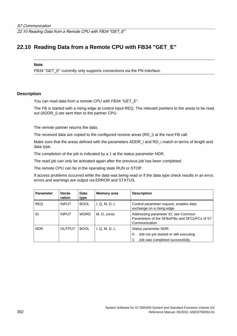
S7 Communication 22.10 Reading Data from a Remote CPU with FB34 "GET_E"
System Software for S7-300/400 System and Standard Functions Volume 2/2 392 Reference Manual, 05/2010, A5E02790053-01
22.10 Reading Data from a Remote CPU with FB34 "GET_E"
Note
FB34 "GET_E" currently only supports connections via the PN interface.
Description You can read data from a remote CPU with FB34 "GET_E".
The FB is started with a rising edge at control input REQ. The relevant pointers to the areas to be read out (ADDR_i) are sent then to the partner CPU.
The remote partner returns the data.
The received data are copied to the configured receive areas (RD_i) at the next FB call.
Make sure that the areas defined with the parameters ADDR_i and RD_i match in terms of length and data type.
The completion of the job is indicated by a 1 at the status parameter NDR.
The read job can only be activated again after the previous job has been completed.
The remote CPU can be in the operating state RUN or STOP.
If access problems occurred while the data was being read or if the data type check results in an error, errors and warnings are output via ERROR and STATUS.
Parameter Decla-
ration Data type
Memory area Description
REQ INPUT BOOL I, Q, M, D, L Control parameter request, enables data exchange on a rising edge.
ID INPUT WORD M, D, const. Addressing parameter ID, see Common Parameters of the SFBs/FBs and SFCs/FCs of S7 Communication
NDR OUTPUT BOOL I, Q, M, D, L Status parameter NDR: 0: Job not yet started or still executing 1: Job was completed successfully.
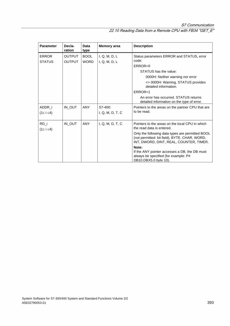
S7 Communication 22.10 Reading Data from a Remote CPU with FB34 "GET_E"
System Software for S7-300/400 System and Standard Functions Volume 2/2 A5E02790053-01 393
Parameter Decla- ration
Data type
Memory area Description
ERROR STATUS
OUTPUT OUTPUT
BOOL WORD
I, Q, M, D, L I, Q, M, D, L
Status parameters ERROR and STATUS, error code: ERROR=0
STATUS has the value: 0000H: Neither warning nor error
<> 0000H: Warning, STATUS provides detailed information.
ERROR=1 An error has occurred. STATUS returns detailed information on the type of error.
ADDR_i (1≤ i ≤4)
IN_OUT ANY S7-400: I, Q, M, D, T, C
Pointers to the areas on the partner CPU that are to be read.
RD_i (1≤ i ≤4)
IN_OUT ANY I, Q, M, D, T, C Pointers to the areas on the local CPU in which the read data is entered. Only the following data types are permitted BOOL (not permitted: bit field), BYTE, CHAR, WORD, INT, DWORD, DINT, REAL, COUNTER, TIMER. Note: If the ANY pointer accesses a DB, the DB must always be specified (for example: P# DB10.DBX5.0 byte 10).
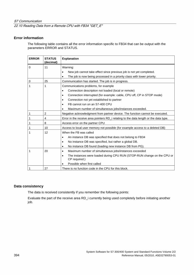
S7 Communication 22.10 Reading Data from a Remote CPU with FB34 "GET_E"
System Software for S7-300/400 System and Standard Functions Volume 2/2 394 Reference Manual, 05/2010, A5E02790053-01
Error information The following table contains all the error information specific to FB34 that can be output with the parameters ERROR and STATUS.
ERROR STATUS
(decimal) Explanation
0 11 Warning: • New job cannot take effect since previous job is not yet completed. • The job is now being processed in a priority class with lower priority.
0 25 Communication has started. The job is in progress. 1 1 Communications problems, for example
• Connection description not loaded (local or remote) • Connection interrupted (for example: cable, CPU off, CP in STOP mode) • Connection not yet established to partner • FB cannot run on an S7-400 CPU • Maximum number of simultaneous jobs/instances exceeded.
1 2 Negative acknowledgment from partner device. The function cannot be executed. 1 4 Error in the receive area pointers RD_i relating to the data length or the data type. 1 8 Access error on the partner CPU 1 10 Access to local user memory not possible (for example access to a deleted DB) 1 12 When the FB was called
• An instance DB was specified that does not belong to FB34 • No instance DB was specified, but rather a global DB. • No instance DB found (loading new instance DB from PG).
1 20 • Maximum number of simultaneous jobs/instances exceeded • The instances were loaded during CPU RUN (STOP-RUN change on the CPU or
CP required.) • Possible when first called
1 27 There is no function code in the CPU for this block.
Data consistency The data is received consistently if you remember the following points:
Evaluate the part of the receive area RD_i currently being used completely before initiating another job.
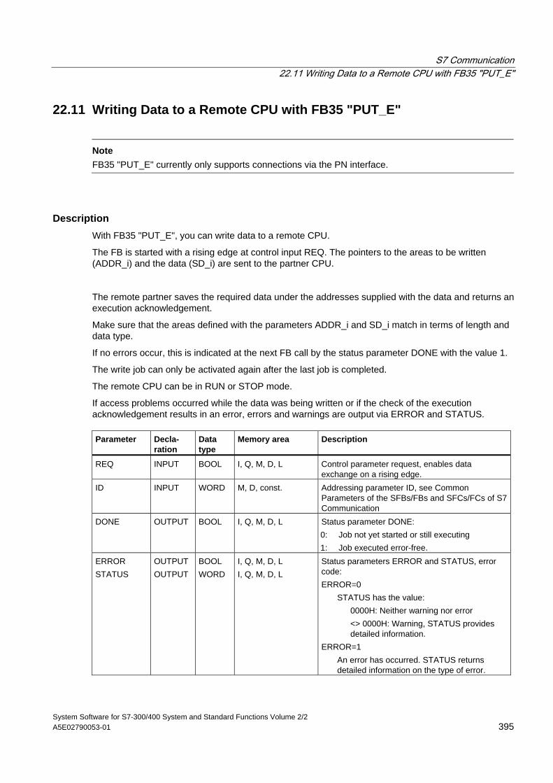
S7 Communication 22.11 Writing Data to a Remote CPU with FB35 "PUT_E"
System Software for S7-300/400 System and Standard Functions Volume 2/2 A5E02790053-01 395
22.11 Writing Data to a Remote CPU with FB35 "PUT_E"
Note
FB35 "PUT_E" currently only supports connections via the PN interface.
Description With FB35 "PUT_E", you can write data to a remote CPU.
The FB is started with a rising edge at control input REQ. The pointers to the areas to be written (ADDR_i) and the data (SD_i) are sent to the partner CPU.
The remote partner saves the required data under the addresses supplied with the data and returns an execution acknowledgement.
Make sure that the areas defined with the parameters ADDR_i and SD_i match in terms of length and data type.
If no errors occur, this is indicated at the next FB call by the status parameter DONE with the value 1.
The write job can only be activated again after the last job is completed.
The remote CPU can be in RUN or STOP mode.
If access problems occurred while the data was being written or if the check of the execution acknowledgement results in an error, errors and warnings are output via ERROR and STATUS. Parameter Decla-
ration Data type
Memory area Description
REQ INPUT BOOL I, Q, M, D, L Control parameter request, enables data exchange on a rising edge.
ID INPUT WORD M, D, const. Addressing parameter ID, see Common Parameters of the SFBs/FBs and SFCs/FCs of S7 Communication
DONE OUTPUT BOOL I, Q, M, D, L Status parameter DONE: 0: Job not yet started or still executing 1: Job executed error-free.
ERROR STATUS
OUTPUT OUTPUT
BOOL WORD
I, Q, M, D, L I, Q, M, D, L
Status parameters ERROR and STATUS, error code: ERROR=0
STATUS has the value: 0000H: Neither warning nor error
<> 0000H: Warning, STATUS provides detailed information.
ERROR=1 An error has occurred. STATUS returns detailed information on the type of error.
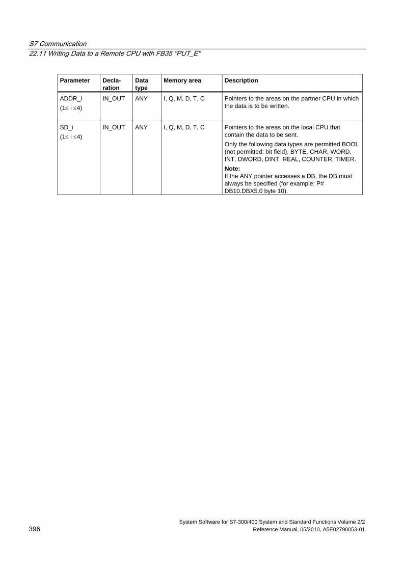
S7 Communication 22.11 Writing Data to a Remote CPU with FB35 "PUT_E"
System Software for S7-300/400 System and Standard Functions Volume 2/2 396 Reference Manual, 05/2010, A5E02790053-01
Parameter Decla- ration
Data type
Memory area Description
ADDR_i (1≤ i ≤4)
IN_OUT ANY I, Q, M, D, T, C Pointers to the areas on the partner CPU in which the data is to be written.
SD_i (1≤ i ≤4)
IN_OUT ANY I, Q, M, D, T, C Pointers to the areas on the local CPU that contain the data to be sent. Only the following data types are permitted BOOL (not permitted: bit field), BYTE, CHAR, WORD, INT, DWORD, DINT, REAL, COUNTER, TIMER. Note: If the ANY pointer accesses a DB, the DB must always be specified (for example: P# DB10.DBX5.0 byte 10).
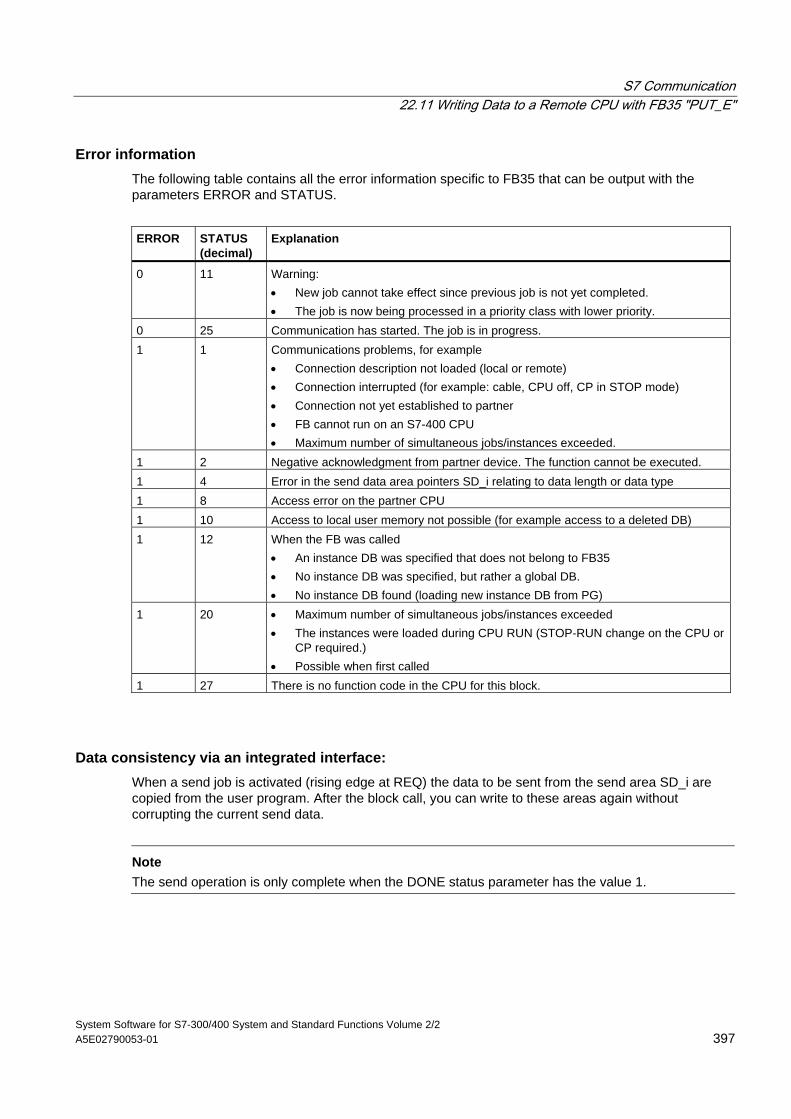
S7 Communication 22.11 Writing Data to a Remote CPU with FB35 "PUT_E"
System Software for S7-300/400 System and Standard Functions Volume 2/2 A5E02790053-01 397
Error information The following table contains all the error information specific to FB35 that can be output with the parameters ERROR and STATUS.
ERROR STATUS
(decimal) Explanation
0 11 Warning: • New job cannot take effect since previous job is not yet completed. • The job is now being processed in a priority class with lower priority.
0 25 Communication has started. The job is in progress. 1 1 Communications problems, for example
• Connection description not loaded (local or remote) • Connection interrupted (for example: cable, CPU off, CP in STOP mode) • Connection not yet established to partner • FB cannot run on an S7-400 CPU • Maximum number of simultaneous jobs/instances exceeded.
1 2 Negative acknowledgment from partner device. The function cannot be executed. 1 4 Error in the send data area pointers SD_i relating to data length or data type 1 8 Access error on the partner CPU 1 10 Access to local user memory not possible (for example access to a deleted DB) 1 12 When the FB was called
• An instance DB was specified that does not belong to FB35 • No instance DB was specified, but rather a global DB. • No instance DB found (loading new instance DB from PG)
1 20 • Maximum number of simultaneous jobs/instances exceeded • The instances were loaded during CPU RUN (STOP-RUN change on the CPU or
CP required.) • Possible when first called
1 27 There is no function code in the CPU for this block.
Data consistency via an integrated interface: When a send job is activated (rising edge at REQ) the data to be sent from the send area SD_i are copied from the user program. After the block call, you can write to these areas again without corrupting the current send data.
Note
The send operation is only complete when the DONE status parameter has the value 1.
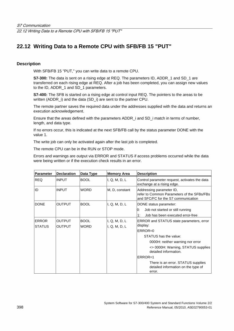
S7 Communication 22.12 Writing Data to a Remote CPU with SFB/FB 15 "PUT"
System Software for S7-300/400 System and Standard Functions Volume 2/2 398 Reference Manual, 05/2010, A5E02790053-01
22.12 Writing Data to a Remote CPU with SFB/FB 15 "PUT"
Description With SFB/FB 15 "PUT," you can write data to a remote CPU.
S7-300: The data is sent on a rising edge at REQ. The parameters ID, ADDR_1 and SD_1 are transferred on each rising edge at REQ. After a job has been completed, you can assign new values to the ID, ADDR_1 and SD_1 parameters.
S7-400: The SFB is started on a rising edge at control input REQ. The pointers to the areas to be written (ADDR_i) and the data (SD_i) are sent to the partner CPU.
The remote partner saves the required data under the addresses supplied with the data and returns an execution acknowledgement.
Ensure that the areas defined with the parameters ADDR_i and SD_i match in terms of number, length, and data type.
If no errors occur, this is indicated at the next SFB/FB call by the status parameter DONE with the value 1.
The write job can only be activated again after the last job is completed.
The remote CPU can be in the RUN or STOP mode.
Errors and warnings are output via ERROR and STATUS if access problems occurred while the data were being written or if the execution check results in an error.
Parameter Declaration Data Type Memory Area Description
REQ INPUT BOOL I, Q, M, D, L Control parameter request, activates the data exchange at a rising edge.
ID INPUT WORD M, D, constant Addressing parameter ID, refer to Common Parameters of the SFBs/FBs and SFC/FC for the S7 communication
DONE OUTPUT BOOL I, Q, M, D, L DONE status parameter: 0: Job not started or still running 1: Job has been executed error-free
ERROR STATUS
OUTPUT OUTPUT
BOOL WORD
I, Q, M, D, L I, Q, M, D, L
ERROR and STATUS state parameters, error display: ERROR=0
STATUS has the value: 0000H: neither warning nor error
<> 0000H: Warning, STATUS supplies detailed information.
ERROR=1 There is an error. STATUS supplies detailed information on the type of error.
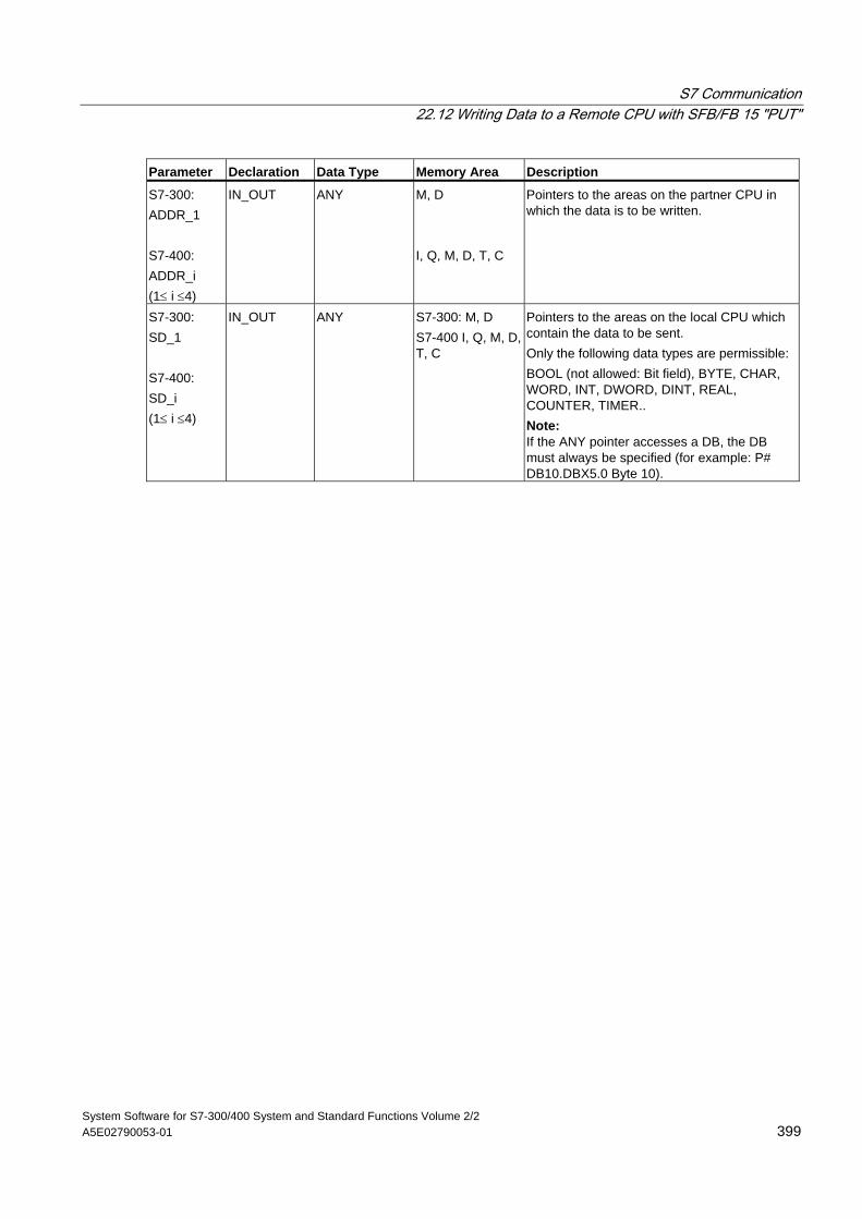
S7 Communication 22.12 Writing Data to a Remote CPU with SFB/FB 15 "PUT"
System Software for S7-300/400 System and Standard Functions Volume 2/2 A5E02790053-01 399
Parameter Declaration Data Type Memory Area Description
S7-300: ADDR_1 S7-400: ADDR_i (1≤ i ≤4)
IN_OUT ANY M, D I, Q, M, D, T, C
Pointers to the areas on the partner CPU in which the data is to be written.
S7-300: SD_1 S7-400: SD_i (1≤ i ≤4)
IN_OUT ANY S7-300: M, D S7-400 I, Q, M, D, T, C
Pointers to the areas on the local CPU which contain the data to be sent. Only the following data types are permissible: BOOL (not allowed: Bit field), BYTE, CHAR, WORD, INT, DWORD, DINT, REAL, COUNTER, TIMER.. Note: If the ANY pointer accesses a DB, the DB must always be specified (for example: P# DB10.DBX5.0 Byte 10).
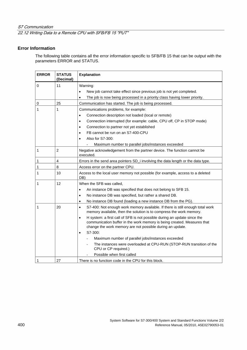
S7 Communication 22.12 Writing Data to a Remote CPU with SFB/FB 15 "PUT"
System Software for S7-300/400 System and Standard Functions Volume 2/2 400 Reference Manual, 05/2010, A5E02790053-01
Error Information The following table contains all the error information specific to SFB/FB 15 that can be output with the parameters ERROR and STATUS.
ERROR
STATUS (Decimal)
Explanation
0 11 Warning: • New job cannot take effect since previous job is not yet completed. • The job is now being processed in a priority class having lower priority.
0 25 Communication has started. The job is being processed. 1 1 Communications problems, for example:
• Connection description not loaded (local or remote) • Connection interrupted (for example: cable, CPU off, CP in STOP mode) • Connection to partner not yet established • FB cannot be run on an S7-400-CPU • Also for S7-300:
- Maximum number to parallel jobs/instances exceeded 1 2 Negative acknowledgement from the partner device. The function cannot be
executed. 1 4 Errors in the send area pointers SD_i involving the data length or the data type. 1 8 Access error on the partner CPU. 1 10 Access to the local user memory not possible (for example, access to a deleted
DB) 1 12 When the SFB was called,
• An instance DB was specified that does not belong to SFB 15. • No instance DB was specified, but rather a shared DB. • No instance DB found (loading a new instance DB from the PG).
1 20 • S7-400: Not enough work memory available. If there is still enough total work memory available, then the solution is to compress the work memory.
• H system: a first call of SFB is not possible during an update since the communication buffer in the work memory is being created. Measures that change the work memory are not possible during an update.
• S7-300: - Maximum number of parallel jobs/instances exceeded - The instances were overloaded at CPU-RUN (STOP-RUN transition of the
CPU or CP required.) - Possible when first called
1 27 There is no function code in the CPU for this block.
S7 Communication 22.12 Writing Data to a Remote CPU with SFB/FB 15 "PUT"
System Software for S7-300/400 System and Standard Functions Volume 2/2 A5E02790053-01 401
Data Consistency for S7-300 In order to ensure data consistency, send area SD_I may not be used again for writing until the current send process has been completed. This is the case when the state parameter DONE has the value 1.
Data Consistency for S7-400 and S7-300 via an integrated interface: When a send operation is activated (rising edge at REQ) the data to be sent from the send area SD_i are copied from the user program. After the block call, you can write to these areas without corrupting the current send data.
Note
The send operation is only complete when the DONE status parameter has the value 1.
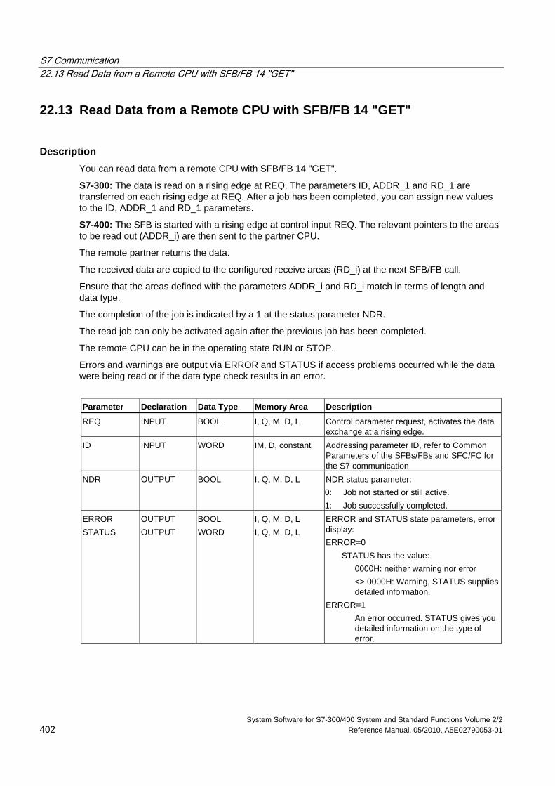
S7 Communication 22.13 Read Data from a Remote CPU with SFB/FB 14 "GET"
System Software for S7-300/400 System and Standard Functions Volume 2/2 402 Reference Manual, 05/2010, A5E02790053-01
22.13 Read Data from a Remote CPU with SFB/FB 14 "GET"
Description You can read data from a remote CPU with SFB/FB 14 "GET".
S7-300: The data is read on a rising edge at REQ. The parameters ID, ADDR_1 and RD_1 are transferred on each rising edge at REQ. After a job has been completed, you can assign new values to the ID, ADDR_1 and RD_1 parameters.
S7-400: The SFB is started with a rising edge at control input REQ. The relevant pointers to the areas to be read out (ADDR_i) are then sent to the partner CPU.
The remote partner returns the data.
The received data are copied to the configured receive areas (RD_i) at the next SFB/FB call.
Ensure that the areas defined with the parameters ADDR_i and RD_i match in terms of length and data type.
The completion of the job is indicated by a 1 at the status parameter NDR.
The read job can only be activated again after the previous job has been completed.
The remote CPU can be in the operating state RUN or STOP.
Errors and warnings are output via ERROR and STATUS if access problems occurred while the data were being read or if the data type check results in an error.
Parameter Declaration Data Type Memory Area Description
REQ INPUT BOOL I, Q, M, D, L Control parameter request, activates the data exchange at a rising edge.
ID INPUT WORD IM, D, constant Addressing parameter ID, refer to Common Parameters of the SFBs/FBs and SFC/FC for the S7 communication
NDR OUTPUT BOOL I, Q, M, D, L NDR status parameter: 0: Job not started or still active. 1: Job successfully completed.
ERROR STATUS
OUTPUT OUTPUT
BOOL WORD
I, Q, M, D, L I, Q, M, D, L
ERROR and STATUS state parameters, error display: ERROR=0
STATUS has the value: 0000H: neither warning nor error
<> 0000H: Warning, STATUS supplies detailed information.
ERROR=1 An error occurred. STATUS gives you detailed information on the type of error.
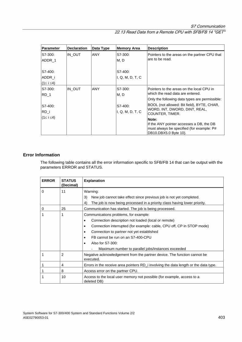
S7 Communication 22.13 Read Data from a Remote CPU with SFB/FB 14 "GET"
System Software for S7-300/400 System and Standard Functions Volume 2/2 A5E02790053-01 403
Parameter Declaration Data Type Memory Area Description
S7-300: ADDR_1 S7-400: ADDR_i (1≤ i ≤4)
IN_OUT ANY S7-300: M, D S7-400: I, Q, M, D, T, C
Pointers to the areas on the partner CPU that are to be read.
S7-300: RD_1 S7-400: RD_i (1≤ i ≤4)
IN_OUT ANY S7-300: M, D S7-400: I, Q, M, D, T, C
Pointers to the areas on the local CPU in which the read data are entered. Only the following data types are permissible: BOOL (not allowed: Bit field), BYTE, CHAR, WORD, INT, DWORD, DINT, REAL, COUNTER, TIMER. Note: If the ANY pointer accesses a DB, the DB must always be specified (for example: P# DB10.DBX5.0 Byte 10).
Error Information The following table contains all the error information specific to SFB/FB 14 that can be output with the parameters ERROR and STATUS.
ERROR
STATUS (Decimal)
Explanation
0 11 Warning: 3) New job cannot take effect since previous job is not yet completed. 4) The job is now being processed in a priority class having lower priority.
0 25 Communication has started. The job is being processed. 1 1 Communications problems, for example:
• Connection description not loaded (local or remote) • Connection interrupted (for example: cable, CPU off, CP in STOP mode) • Connection to partner not yet established • FB cannot be run on an S7-400-CPU • Also for S7-300:
- Maximum number to parallel jobs/instances exceeded 1 2 Negative acknowledgement from the partner device. The function cannot be
executed. 1 4 Errors in the receive area pointers RD_i involving the data length or the data type. 1 8 Access error on the partner CPU. 1 10 Access to the local user memory not possible (for example, access to a
deleted DB)
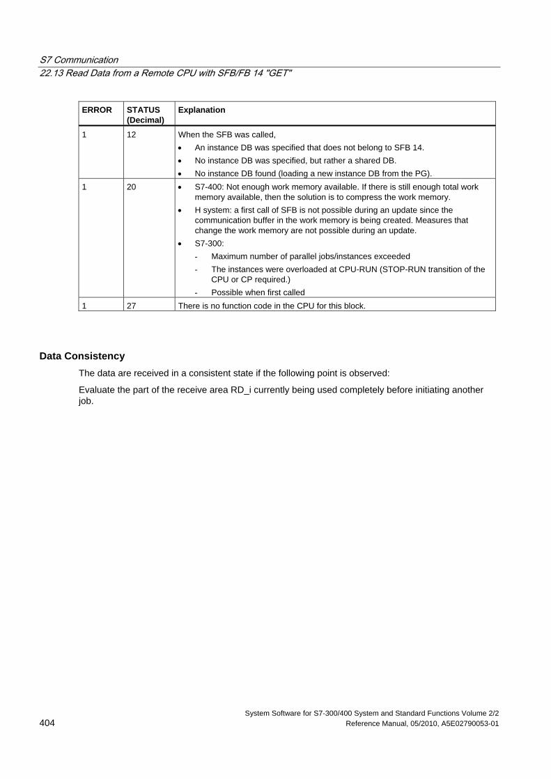
S7 Communication 22.13 Read Data from a Remote CPU with SFB/FB 14 "GET"
System Software for S7-300/400 System and Standard Functions Volume 2/2 404 Reference Manual, 05/2010, A5E02790053-01
ERROR
STATUS (Decimal)
Explanation
1 12 When the SFB was called, • An instance DB was specified that does not belong to SFB 14. • No instance DB was specified, but rather a shared DB. • No instance DB found (loading a new instance DB from the PG).
1 20 • S7-400: Not enough work memory available. If there is still enough total work memory available, then the solution is to compress the work memory.
• H system: a first call of SFB is not possible during an update since the communication buffer in the work memory is being created. Measures that change the work memory are not possible during an update.
• S7-300: - Maximum number of parallel jobs/instances exceeded - The instances were overloaded at CPU-RUN (STOP-RUN transition of the
CPU or CP required.) - Possible when first called
1 27 There is no function code in the CPU for this block.
Data Consistency The data are received in a consistent state if the following point is observed:
Evaluate the part of the receive area RD_i currently being used completely before initiating another job.
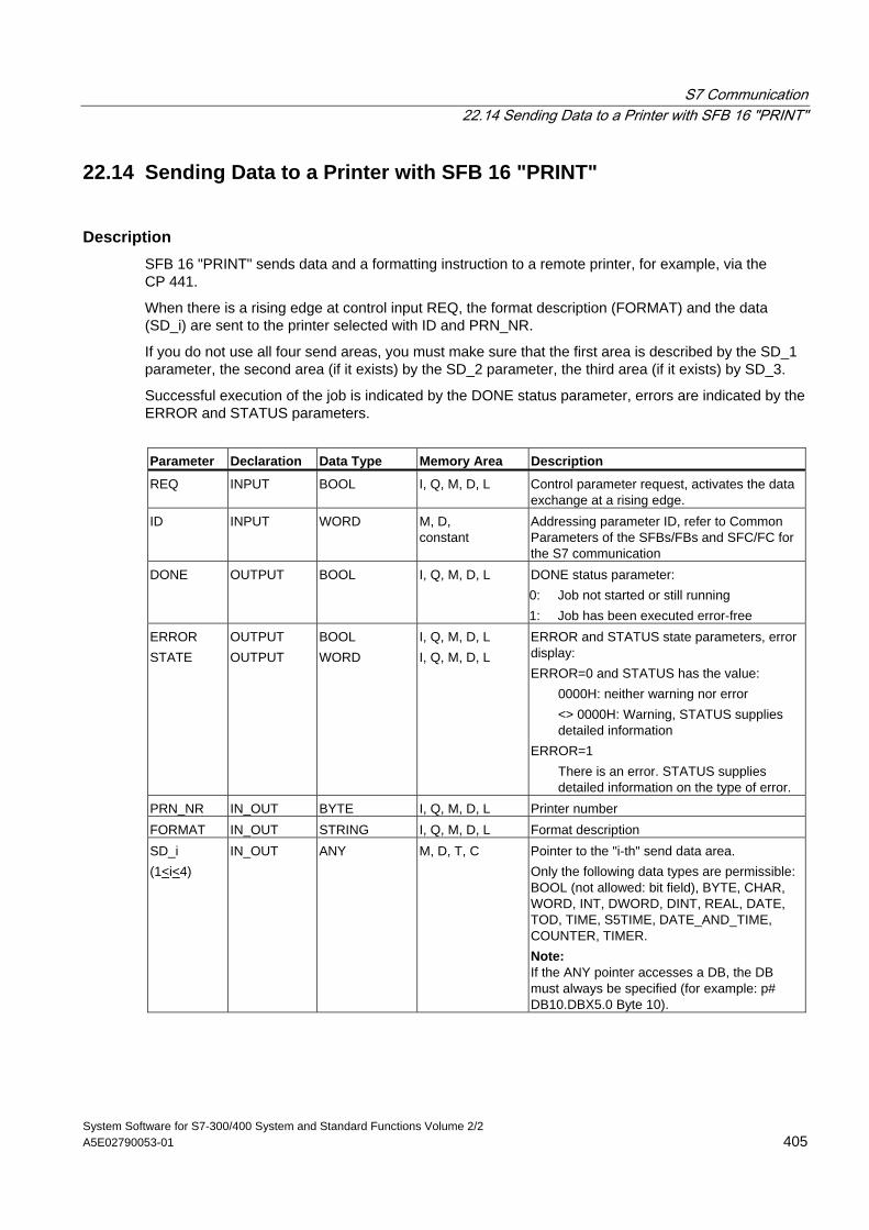
S7 Communication 22.14 Sending Data to a Printer with SFB 16 "PRINT"
System Software for S7-300/400 System and Standard Functions Volume 2/2 A5E02790053-01 405
22.14 Sending Data to a Printer with SFB 16 "PRINT"
Description SFB 16 "PRINT" sends data and a formatting instruction to a remote printer, for example, via the CP 441.
When there is a rising edge at control input REQ, the format description (FORMAT) and the data (SD_i) are sent to the printer selected with ID and PRN_NR.
If you do not use all four send areas, you must make sure that the first area is described by the SD_1 parameter, the second area (if it exists) by the SD_2 parameter, the third area (if it exists) by SD_3.
Successful execution of the job is indicated by the DONE status parameter, errors are indicated by the ERROR and STATUS parameters.
Parameter Declaration Data Type Memory Area Description
REQ INPUT BOOL I, Q, M, D, L Control parameter request, activates the data exchange at a rising edge.
ID INPUT WORD M, D, constant
Addressing parameter ID, refer to Common Parameters of the SFBs/FBs and SFC/FC for the S7 communication
DONE OUTPUT BOOL I, Q, M, D, L DONE status parameter: 0: Job not started or still running 1: Job has been executed error-free
ERROR STATE
OUTPUT OUTPUT
BOOL WORD
I, Q, M, D, L I, Q, M, D, L
ERROR and STATUS state parameters, error display: ERROR=0 and STATUS has the value:
0000H: neither warning nor error <> 0000H: Warning, STATUS supplies detailed information
ERROR=1 There is an error. STATUS supplies detailed information on the type of error.
PRN_NR IN_OUT BYTE I, Q, M, D, L Printer number FORMAT IN_OUT STRING I, Q, M, D, L Format description SD_i (1<i<4)
IN_OUT ANY M, D, T, C Pointer to the "i-th" send data area. Only the following data types are permissible: BOOL (not allowed: bit field), BYTE, CHAR, WORD, INT, DWORD, DINT, REAL, DATE, TOD, TIME, S5TIME, DATE_AND_TIME, COUNTER, TIMER. Note: If the ANY pointer accesses a DB, the DB must always be specified (for example: p# DB10.DBX5.0 Byte 10).
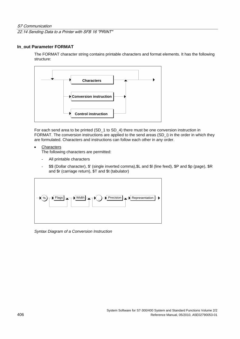
S7 Communication 22.14 Sending Data to a Printer with SFB 16 "PRINT"
System Software for S7-300/400 System and Standard Functions Volume 2/2 406 Reference Manual, 05/2010, A5E02790053-01
In_out Parameter FORMAT The FORMAT character string contains printable characters and format elements. It has the following structure:
Conversion instruction
Characters
Control instruction
For each send area to be printed (SD_1 to SD_4) there must be one conversion instruction in FORMAT. The conversion instructions are applied to the send areas (SD_i) in the order in which they are formulated. Characters and instructions can follow each other in any order.
• Characters The following characters are permitted:
- All printable characters
- $$ (Dollar character), $' (single inverted comma),$L and $l (line feed), $P and $p (page), $R and $r (carriage return), $T and $t (tabulator)
% .Flags RepresentationWidth Precision
Syntax Diagram of a Conversion Instruction
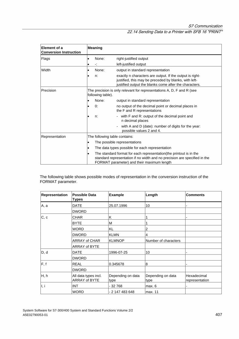
S7 Communication 22.14 Sending Data to a Printer with SFB 16 "PRINT"
System Software for S7-300/400 System and Standard Functions Volume 2/2 A5E02790053-01 407
Element of a Conversion Instruction
Meaning
Flags • None: right-justified output • -: left-justified output
Width • None: output in standard representation • n: exactly n characters are output. If the output is right-
justified, this may be preceded by blanks, with left- justified output the blanks come after the characters.
Precision The precision is only relevant for representations A, D, F and R (see following table). • None: output in standard representation • 0: no output of the decimal point or decimal places in
the F and R representations • n: - with F and R: output of the decimal point and
n decimal places - with A and D (date): number of digits for the year: possible values 2 and 4.
Representation The following table contains: • The possible representations • The data types possible for each representation • The standard format for each representation(the printout is in the
standard representation if no width and no precision are specified in the FORMAT parameter) and their maximum length
The following table shows possible modes of representation in the conversion instruction of the FORMAT parameter.
Representation
Possible Data Types
Example
Length
Comments
DATE 25.07.1996 10 - A, a DWORD CHAR K 1 - BYTE M 1 WORD KL 2 DWORD KLMN 4 ARRAY of CHAR KLMNOP Number of characters
C, c
ARRAY of BYTE DATE 1996-07-25 10 - D, d DWORD REAL 0.345678 8 - F, f DWORD
H, h All data types incl. ARRAY of BYTE
Depending on data type
Depending on data type
Hexadecimal representation
INT - 32 768 max. 6 - I, i WORD - 2 147 483 648 max. 11
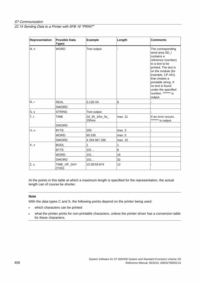
S7 Communication 22.14 Sending Data to a Printer with SFB 16 "PRINT"
System Software for S7-300/400 System and Standard Functions Volume 2/2 408 Reference Manual, 05/2010, A5E02790053-01
Representation
Possible Data Types
Example
Length
Comments
N, n WORD Text output - The corresponding send area SD_i contains a reference (number) to a text to be printed. The text is on the module (for example, CP 441) that creates a printable string. If no text is found under the specified number, ****** is output.
REAL 0.12E-04 8 - R, r DWORD
S, s STRING Text output - TIME 2d_3h_10m_5s_
250ms max. 21 If an error occurs,
****** is output. T, t
DWORD BYTE 255 max. 3 - WORD 65 535 max. 5
U, u
DWORD 4 294 967 295 max. 10 BOOL 1 1 - BYTE 101 .. 8 WORD 101 .. 16
X, x
DWORD 101 .. 32 Z, z TIME_OF_DAY
(TOD) 15:38:59.874 12 -
At the points in this table at which a maximum length is specified for the representation, the actual length can of course be shorter.
Note
With the data types C and S, the following points depend on the printer being used:
• which characters can be printed
• what the printer prints for non-printable characters, unless the printer driver has a conversion table for these characters.
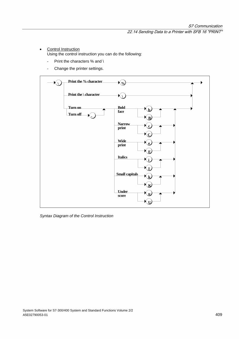
S7 Communication 22.14 Sending Data to a Printer with SFB 16 "PRINT"
System Software for S7-300/400 System and Standard Functions Volume 2/2 A5E02790053-01 409
• Control Instruction Using the control instruction you can do the following:
- Print the characters % and \
- Change the printer settings.
Underscore u
U
\
Small capitalsk
K
Italicsi
I
Wideprint e
E
Narrowprint
Boldface
Print the % character
Print the \ character
Turn on
Turn off
\
%
-
b
B
c
C
Syntax Diagram of the Control Instruction
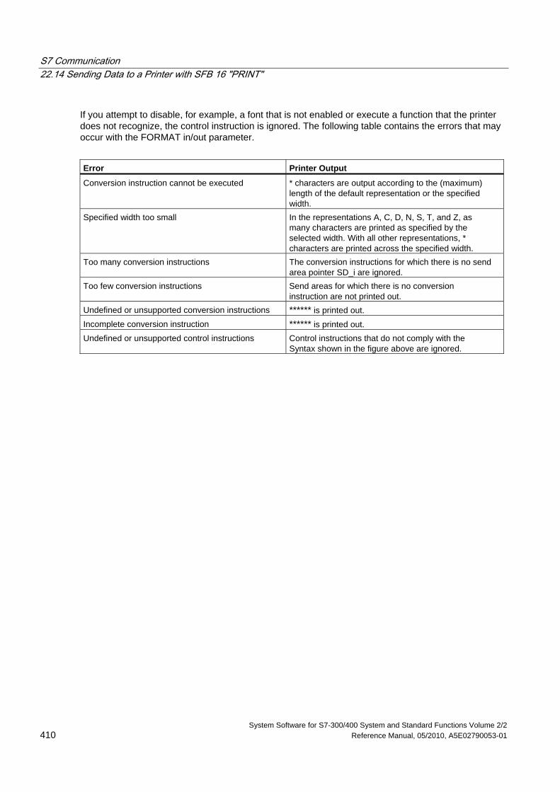
S7 Communication 22.14 Sending Data to a Printer with SFB 16 "PRINT"
System Software for S7-300/400 System and Standard Functions Volume 2/2 410 Reference Manual, 05/2010, A5E02790053-01
If you attempt to disable, for example, a font that is not enabled or execute a function that the printer does not recognize, the control instruction is ignored. The following table contains the errors that may occur with the FORMAT in/out parameter.
Error Printer Output
Conversion instruction cannot be executed * characters are output according to the (maximum) length of the default representation or the specified width.
Specified width too small In the representations A, C, D, N, S, T, and Z, as many characters are printed as specified by the selected width. With all other representations, * characters are printed across the specified width.
Too many conversion instructions The conversion instructions for which there is no send area pointer SD_i are ignored.
Too few conversion instructions Send areas for which there is no conversion instruction are not printed out.
Undefined or unsupported conversion instructions ****** is printed out. Incomplete conversion instruction ****** is printed out. Undefined or unsupported control instructions Control instructions that do not comply with the
Syntax shown in the figure above are ignored.
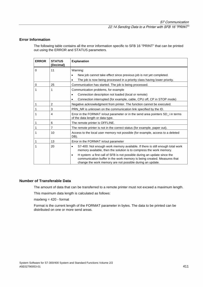
S7 Communication 22.14 Sending Data to a Printer with SFB 16 "PRINT"
System Software for S7-300/400 System and Standard Functions Volume 2/2 A5E02790053-01 411
Error Information The following table contains all the error information specific to SFB 16 "PRINT" that can be printed out using the ERROR and STATUS parameters.
ERROR
STATUS (Decimal)
Explanation
0 11 Warning: • New job cannot take effect since previous job is not yet completed. • The job is now being processed in a priority class having lower priority.
0 25 Communication has started. The job is being processed. 1 1 Communication problems, for example
• Connection description not loaded (local or remote) • Connection interrupted (for example, cable, CPU off, CP in STOP mode)
1 2 Negative acknowledgment from printer. The function cannot be executed. 1 3 PRN_NR is unknown on the communication link specified by the ID. 1 4 Error in the FORMAT in/out parameter or in the send area pointers SD_i in terms
of the data length or data type. 1 6 The remote printer is OFFLINE. 1 7 The remote printer is not in the correct status (for example, paper out). 1 10 Access to the local user memory not possible (for example, access to a deleted
DB). 1 13 Error in the FORMAT in/out parameter 1 20 • S7-400: Not enough work memory available. If there is still enough total work
memory available, then the solution is to compress the work memory. • H system: a first call of SFB is not possible during an update since the
communication buffer in the work memory is being created. Measures that change the work memory are not possible during an update.
Number of Transferable Data The amount of data that can be transferred to a remote printer must not exceed a maximum length.
This maximum data length is calculated as follows:
maxleng = 420 - format
Format is the current length of the FORMAT parameter in bytes. The data to be printed can be distributed on one or more send areas.
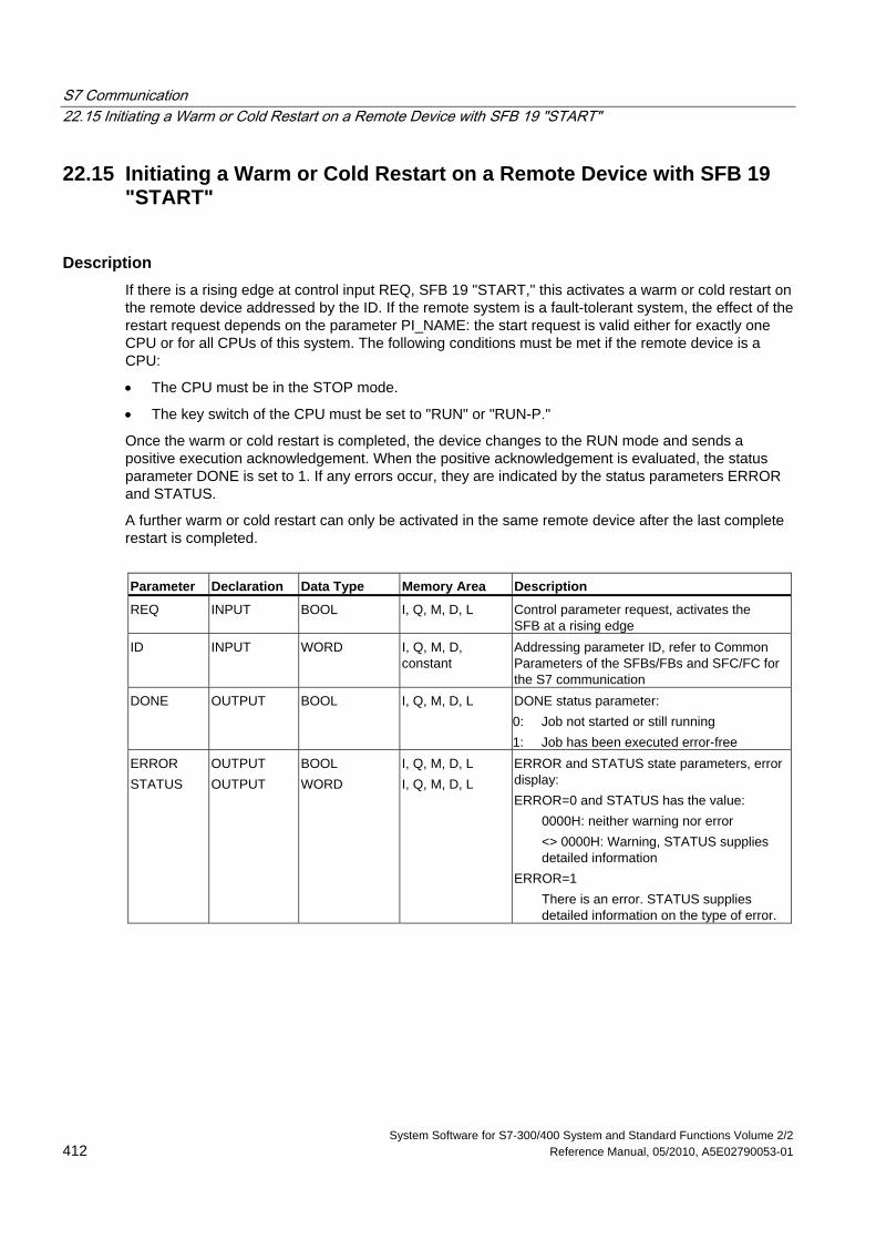
S7 Communication 22.15 Initiating a Warm or Cold Restart on a Remote Device with SFB 19 "START"
System Software for S7-300/400 System and Standard Functions Volume 2/2 412 Reference Manual, 05/2010, A5E02790053-01
22.15 Initiating a Warm or Cold Restart on a Remote Device with SFB 19 "START"
Description If there is a rising edge at control input REQ, SFB 19 "START," this activates a warm or cold restart on the remote device addressed by the ID. If the remote system is a fault-tolerant system, the effect of the restart request depends on the parameter PI_NAME: the start request is valid either for exactly one CPU or for all CPUs of this system. The following conditions must be met if the remote device is a CPU:
• The CPU must be in the STOP mode.
• The key switch of the CPU must be set to "RUN" or "RUN-P."
Once the warm or cold restart is completed, the device changes to the RUN mode and sends a positive execution acknowledgement. When the positive acknowledgement is evaluated, the status parameter DONE is set to 1. If any errors occur, they are indicated by the status parameters ERROR and STATUS.
A further warm or cold restart can only be activated in the same remote device after the last complete restart is completed.
Parameter Declaration Data Type Memory Area Description
REQ INPUT BOOL I, Q, M, D, L Control parameter request, activates the SFB at a rising edge
ID INPUT WORD I, Q, M, D, constant
Addressing parameter ID, refer to Common Parameters of the SFBs/FBs and SFC/FC for the S7 communication
DONE OUTPUT BOOL I, Q, M, D, L DONE status parameter: 0: Job not started or still running 1: Job has been executed error-free
ERROR STATUS
OUTPUT OUTPUT
BOOL WORD
I, Q, M, D, L I, Q, M, D, L
ERROR and STATUS state parameters, error display: ERROR=0 and STATUS has the value:
0000H: neither warning nor error <> 0000H: Warning, STATUS supplies detailed information
ERROR=1 There is an error. STATUS supplies detailed information on the type of error.
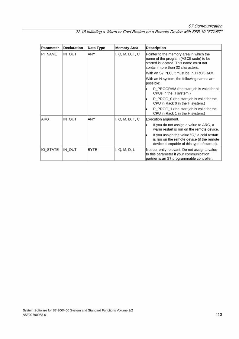
S7 Communication 22.15 Initiating a Warm or Cold Restart on a Remote Device with SFB 19 "START"
System Software for S7-300/400 System and Standard Functions Volume 2/2 A5E02790053-01 413
Parameter Declaration Data Type Memory Area Description
PI_NAME IN_OUT ANY I, Q, M, D, T, C Pointer to the memory area in which the name of the program (ASCII code) to be started is located. This name must not contain more than 32 characters. With an S7 PLC, it must be P_PROGRAM. With an H system, the following names are possible: • P_PROGRAM (the start job is valid for all
CPUs in the H system.) • P_PROG_0 (the start job is valid for the
CPU in Rack 0 in the H system.) • P_PROG_1 (the start job is valid for the
CPU in Rack 1 in the H system.) ARG IN_OUT ANY I, Q, M, D, T, C Execution argument.
• If you do not assign a value to ARG, a warm restart is run on the remote device.
• If you assign the value "C," a cold restart is run on the remote device (if the remote device is capable of this type of startup).
IO_STATE IN_OUT BYTE I, Q, M, D, L Not currently relevant. Do not assign a value to this parameter if your communication partner is an S7 programmable controller.
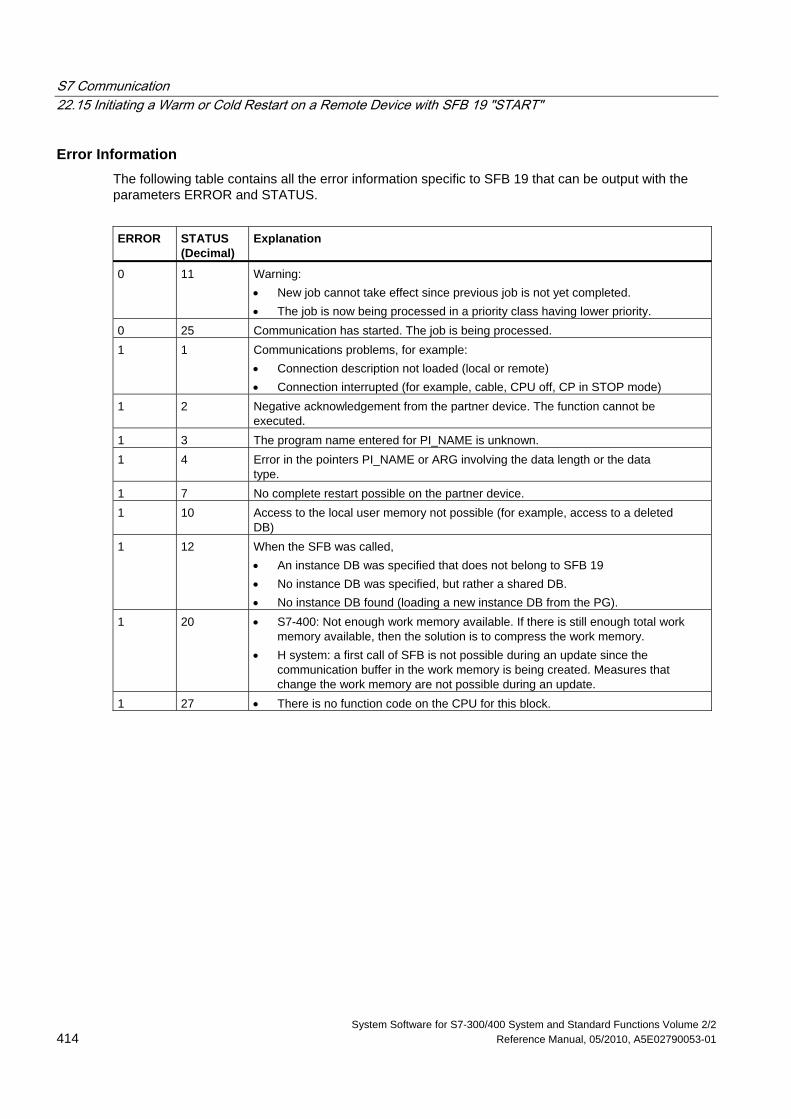
S7 Communication 22.15 Initiating a Warm or Cold Restart on a Remote Device with SFB 19 "START"
System Software for S7-300/400 System and Standard Functions Volume 2/2 414 Reference Manual, 05/2010, A5E02790053-01
Error Information The following table contains all the error information specific to SFB 19 that can be output with the parameters ERROR and STATUS.
ERROR
STATUS (Decimal)
Explanation
0 11 Warning: • New job cannot take effect since previous job is not yet completed. • The job is now being processed in a priority class having lower priority.
0 25 Communication has started. The job is being processed. 1 1 Communications problems, for example:
• Connection description not loaded (local or remote) • Connection interrupted (for example, cable, CPU off, CP in STOP mode)
1 2 Negative acknowledgement from the partner device. The function cannot be executed.
1 3 The program name entered for PI_NAME is unknown. 1 4 Error in the pointers PI_NAME or ARG involving the data length or the data
type. 1 7 No complete restart possible on the partner device. 1 10 Access to the local user memory not possible (for example, access to a deleted
DB) 1 12 When the SFB was called,
• An instance DB was specified that does not belong to SFB 19 • No instance DB was specified, but rather a shared DB. • No instance DB found (loading a new instance DB from the PG).
1 20 • S7-400: Not enough work memory available. If there is still enough total work memory available, then the solution is to compress the work memory.
• H system: a first call of SFB is not possible during an update since the communication buffer in the work memory is being created. Measures that change the work memory are not possible during an update.
1 27 • There is no function code on the CPU for this block.
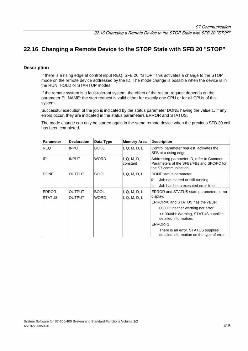
S7 Communication 22.16 Changing a Remote Device to the STOP State with SFB 20 "STOP"
System Software for S7-300/400 System and Standard Functions Volume 2/2 A5E02790053-01 415
22.16 Changing a Remote Device to the STOP State with SFB 20 "STOP"
Description If there is a rising edge at control input REQ, SFB 20 "STOP," this activates a change to the STOP mode on the remote device addressed by the ID. The mode change is possible when the device is in the RUN, HOLD or STARTUP modes.
If the remote system is a fault-tolerant system, the effect of the restart request depends on the parameter PI_NAME: the start request is valid either for exactly one CPU or for all CPUs of this system.
Successful execution of the job is indicated by the status parameter DONE having the value 1. If any errors occur, they are indicated in the status parameters ERROR and STATUS.
The mode change can only be started again in the same remote device when the previous SFB 20 call has been completed.
Parameter Declaration Data Type Memory Area Description
REQ INPUT BOOL I, Q, M, D, L Control parameter request, activates the SFB at a rising edge
ID INPUT WORD I, Q, M, D, constant
Addressing parameter ID, refer to Common Parameters of the SFBs/FBs and SFC/FC for the S7 communication
DONE OUTPUT BOOL I, Q, M, D, L DONE status parameter: 0: Job not started or still running 1: Job has been executed error-free
ERROR STATUS
OUTPUT OUTPUT
BOOL WORD
I, Q, M, D, L I, Q, M, D, L
ERROR and STATUS state parameters, error display: ERROR=0 and STATUS has the value:
0000H: neither warning nor error <> 0000H: Warning, STATUS supplies detailed information.
ERROR=1 There is an error. STATUS supplies detailed information on the type of error.
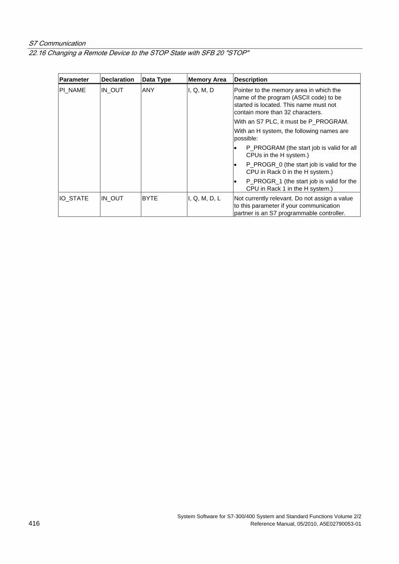
S7 Communication 22.16 Changing a Remote Device to the STOP State with SFB 20 "STOP"
System Software for S7-300/400 System and Standard Functions Volume 2/2 416 Reference Manual, 05/2010, A5E02790053-01
Parameter Declaration Data Type Memory Area Description
PI_NAME IN_OUT ANY I, Q, M, D Pointer to the memory area in which the name of the program (ASCII code) to be started is located. This name must not contain more than 32 characters. With an S7 PLC, it must be P_PROGRAM. With an H system, the following names are possible: • P_PROGRAM (the start job is valid for all
CPUs in the H system.) • P_PROGR_0 (the start job is valid for the
CPU in Rack 0 in the H system.) • P_PROGR_1 (the start job is valid for the
CPU in Rack 1 in the H system.) IO_STATE IN_OUT BYTE I, Q, M, D, L Not currently relevant. Do not assign a value
to this parameter if your communication partner is an S7 programmable controller.
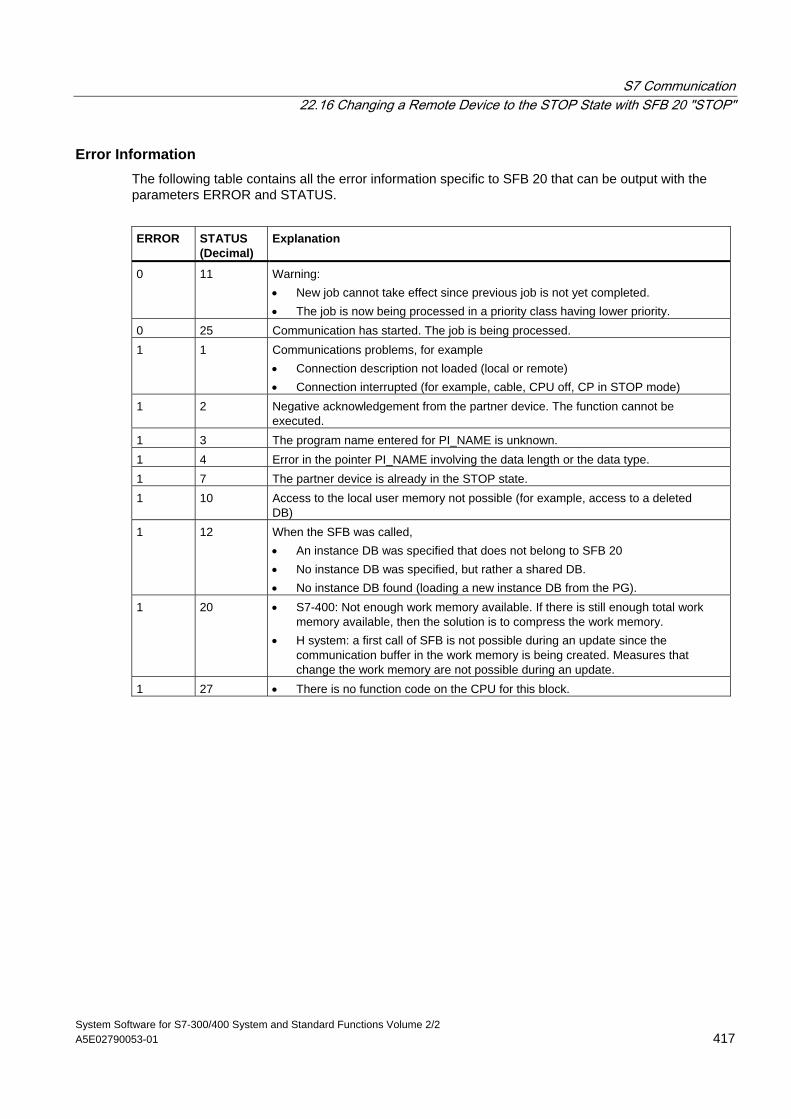
S7 Communication 22.16 Changing a Remote Device to the STOP State with SFB 20 "STOP"
System Software for S7-300/400 System and Standard Functions Volume 2/2 A5E02790053-01 417
Error Information The following table contains all the error information specific to SFB 20 that can be output with the parameters ERROR and STATUS.
ERROR
STATUS (Decimal)
Explanation
0 11 Warning: • New job cannot take effect since previous job is not yet completed. • The job is now being processed in a priority class having lower priority.
0 25 Communication has started. The job is being processed. 1 1 Communications problems, for example
• Connection description not loaded (local or remote) • Connection interrupted (for example, cable, CPU off, CP in STOP mode)
1 2 Negative acknowledgement from the partner device. The function cannot be executed.
1 3 The program name entered for PI_NAME is unknown. 1 4 Error in the pointer PI_NAME involving the data length or the data type. 1 7 The partner device is already in the STOP state. 1 10 Access to the local user memory not possible (for example, access to a deleted
DB) 1 12 When the SFB was called,
• An instance DB was specified that does not belong to SFB 20 • No instance DB was specified, but rather a shared DB. • No instance DB found (loading a new instance DB from the PG).
1 20 • S7-400: Not enough work memory available. If there is still enough total work memory available, then the solution is to compress the work memory.
• H system: a first call of SFB is not possible during an update since the communication buffer in the work memory is being created. Measures that change the work memory are not possible during an update.
1 27 • There is no function code on the CPU for this block.
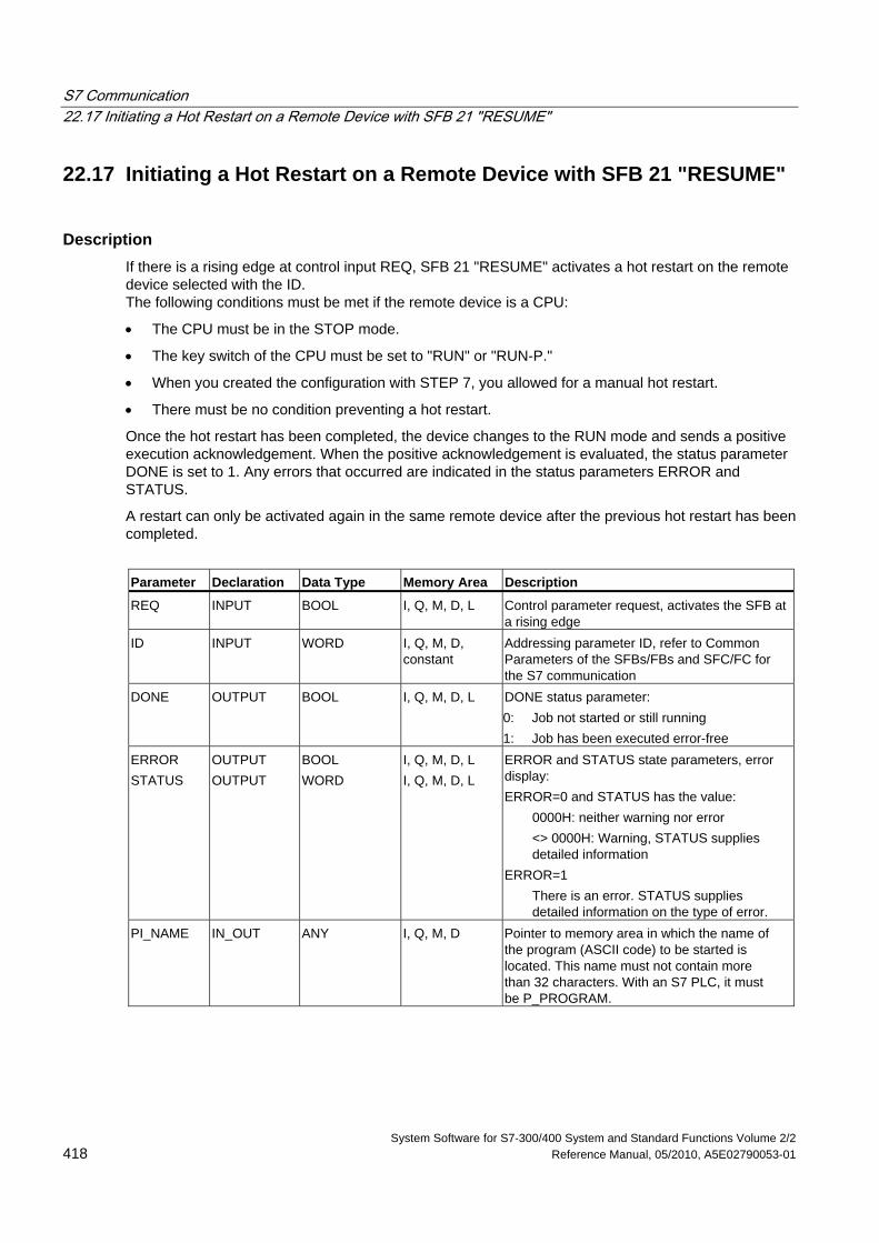
S7 Communication 22.17 Initiating a Hot Restart on a Remote Device with SFB 21 "RESUME"
System Software for S7-300/400 System and Standard Functions Volume 2/2 418 Reference Manual, 05/2010, A5E02790053-01
22.17 Initiating a Hot Restart on a Remote Device with SFB 21 "RESUME"
Description If there is a rising edge at control input REQ, SFB 21 "RESUME" activates a hot restart on the remote device selected with the ID. The following conditions must be met if the remote device is a CPU:
• The CPU must be in the STOP mode.
• The key switch of the CPU must be set to "RUN" or "RUN-P."
• When you created the configuration with STEP 7, you allowed for a manual hot restart.
• There must be no condition preventing a hot restart.
Once the hot restart has been completed, the device changes to the RUN mode and sends a positive execution acknowledgement. When the positive acknowledgement is evaluated, the status parameter DONE is set to 1. Any errors that occurred are indicated in the status parameters ERROR and STATUS.
A restart can only be activated again in the same remote device after the previous hot restart has been completed.
Parameter Declaration Data Type Memory Area Description
REQ INPUT BOOL I, Q, M, D, L Control parameter request, activates the SFB at a rising edge
ID INPUT WORD I, Q, M, D, constant
Addressing parameter ID, refer to Common Parameters of the SFBs/FBs and SFC/FC for the S7 communication
DONE OUTPUT BOOL I, Q, M, D, L DONE status parameter: 0: Job not started or still running 1: Job has been executed error-free
ERROR STATUS
OUTPUT OUTPUT
BOOL WORD
I, Q, M, D, L I, Q, M, D, L
ERROR and STATUS state parameters, error display: ERROR=0 and STATUS has the value:
0000H: neither warning nor error <> 0000H: Warning, STATUS supplies detailed information
ERROR=1 There is an error. STATUS supplies detailed information on the type of error.
PI_NAME IN_OUT ANY I, Q, M, D Pointer to memory area in which the name of the program (ASCII code) to be started is located. This name must not contain more than 32 characters. With an S7 PLC, it must be P_PROGRAM.
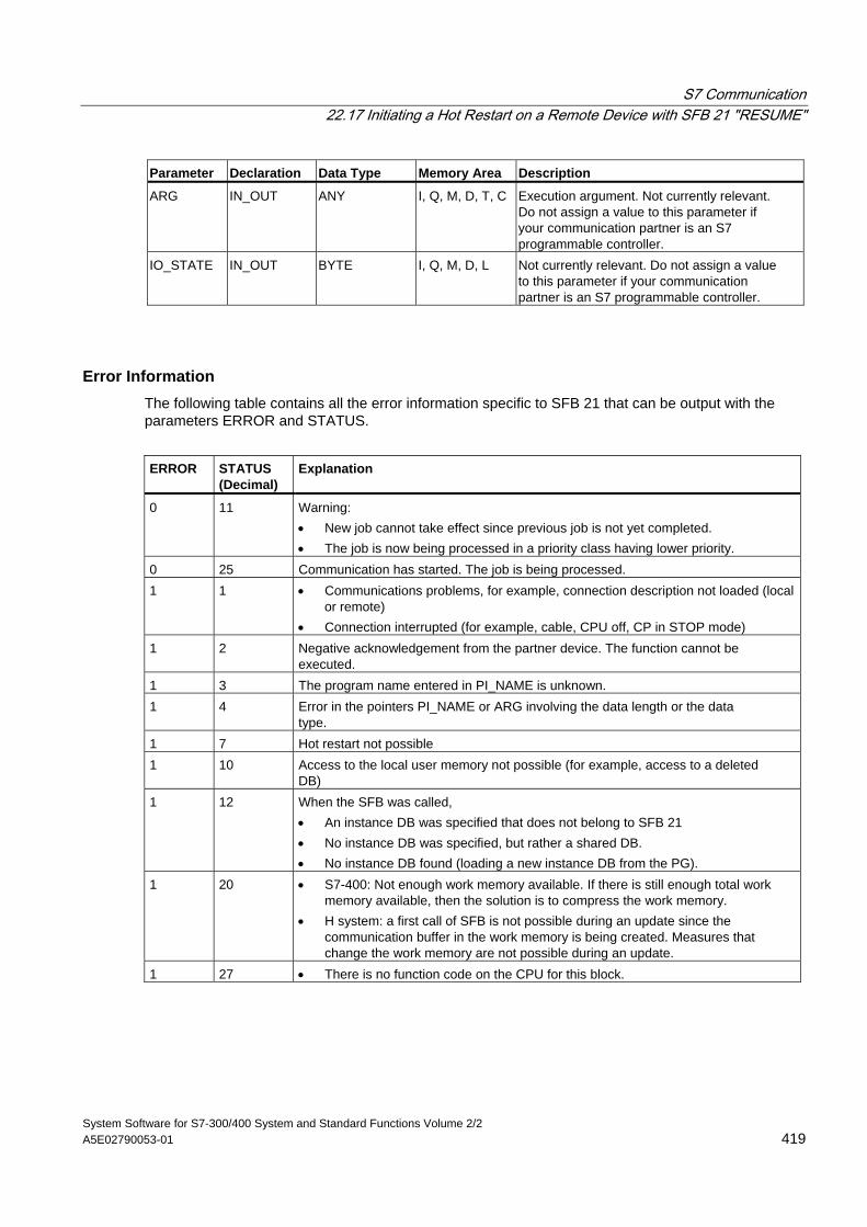
S7 Communication 22.17 Initiating a Hot Restart on a Remote Device with SFB 21 "RESUME"
System Software for S7-300/400 System and Standard Functions Volume 2/2 A5E02790053-01 419
Parameter Declaration Data Type Memory Area Description
ARG IN_OUT ANY I, Q, M, D, T, C Execution argument. Not currently relevant. Do not assign a value to this parameter if your communication partner is an S7 programmable controller.
IO_STATE IN_OUT BYTE I, Q, M, D, L Not currently relevant. Do not assign a value to this parameter if your communication partner is an S7 programmable controller.
Error Information The following table contains all the error information specific to SFB 21 that can be output with the parameters ERROR and STATUS.
ERROR
STATUS (Decimal)
Explanation
0 11 Warning: • New job cannot take effect since previous job is not yet completed. • The job is now being processed in a priority class having lower priority.
0 25 Communication has started. The job is being processed. 1 1 • Communications problems, for example, connection description not loaded (local
or remote) • Connection interrupted (for example, cable, CPU off, CP in STOP mode)
1 2 Negative acknowledgement from the partner device. The function cannot be executed.
1 3 The program name entered in PI_NAME is unknown. 1 4 Error in the pointers PI_NAME or ARG involving the data length or the data
type. 1 7 Hot restart not possible 1 10 Access to the local user memory not possible (for example, access to a deleted
DB) 1 12 When the SFB was called,
• An instance DB was specified that does not belong to SFB 21 • No instance DB was specified, but rather a shared DB. • No instance DB found (loading a new instance DB from the PG).
1 20 • S7-400: Not enough work memory available. If there is still enough total work memory available, then the solution is to compress the work memory.
• H system: a first call of SFB is not possible during an update since the communication buffer in the work memory is being created. Measures that change the work memory are not possible during an update.
1 27 • There is no function code on the CPU for this block.
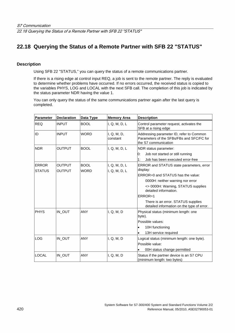
S7 Communication 22.18 Querying the Status of a Remote Partner with SFB 22 "STATUS"
System Software for S7-300/400 System and Standard Functions Volume 2/2 420 Reference Manual, 05/2010, A5E02790053-01
22.18 Querying the Status of a Remote Partner with SFB 22 "STATUS"
Description Using SFB 22 "STATUS," you can query the status of a remote communications partner.
If there is a rising edge at control input REQ, a job is sent to the remote partner. The reply is evaluated to determine whether problems have occurred. If no errors occurred, the received status is copied to the variables PHYS, LOG and LOCAL with the next SFB call. The completion of this job is indicated by the status parameter NDR having the value 1.
You can only query the status of the same communications partner again after the last query is completed.
Parameter Declaration Data Type Memory Area Description
REQ INPUT BOOL I, Q, M, D, L Control parameter request, activates the SFB at a rising edge
ID INPUT WORD I, Q, M, D, constant
Addressing parameter ID, refer to Common Parameters of the SFBs/FBs and SFC/FC for the S7 communication
NDR OUTPUT BOOL I, Q, M, D, L NDR status parameter: 0: Job not started or still running 1: Job has been executed error-free
ERROR STATUS
OUTPUT OUTPUT
BOOL WORD
I, Q, M, D, L I, Q, M, D, L
ERROR and STATUS state parameters, error display: ERROR=0 and STATUS has the value:
0000H: neither warning nor error <> 0000H: Warning, STATUS supplies detailed information.
ERROR=1 There is an error. STATUS supplies detailed information on the type of error.
PHYS IN_OUT ANY I, Q, M, D Physical status (minimum length: one byte). Possible values: • 10H functioning • 13H service required
LOG IN_OUT ANY I, Q, M, D Logical status (minimum length: one byte). Possible value: • 00H status change permitted
LOCAL IN_OUT ANY I, Q, M, D Status if the partner device is an S7 CPU (minimum length: two bytes)
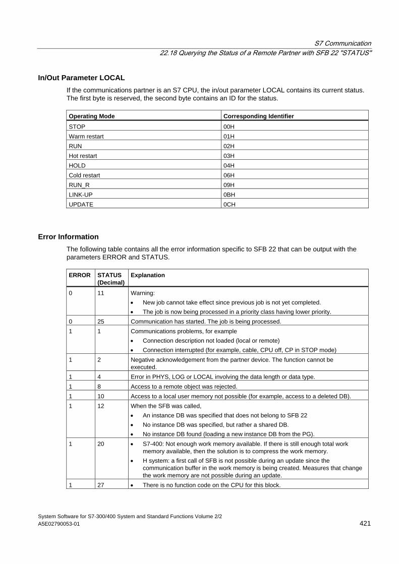
S7 Communication 22.18 Querying the Status of a Remote Partner with SFB 22 "STATUS"
System Software for S7-300/400 System and Standard Functions Volume 2/2 A5E02790053-01 421
In/Out Parameter LOCAL If the communications partner is an S7 CPU, the in/out parameter LOCAL contains its current status. The first byte is reserved, the second byte contains an ID for the status. Operating Mode Corresponding Identifier
STOP 00H Warm restart 01H RUN 02H Hot restart 03H HOLD 04H Cold restart 06H RUN_R 09H LINK-UP 0BH UPDATE 0CH
Error Information The following table contains all the error information specific to SFB 22 that can be output with the parameters ERROR and STATUS. ERROR
STATUS (Decimal)
Explanation
0 11 Warning: • New job cannot take effect since previous job is not yet completed. • The job is now being processed in a priority class having lower priority.
0 25 Communication has started. The job is being processed. 1 1 Communications problems, for example
• Connection description not loaded (local or remote) • Connection interrupted (for example, cable, CPU off, CP in STOP mode)
1 2 Negative acknowledgement from the partner device. The function cannot be executed.
1 4 Error in PHYS, LOG or LOCAL involving the data length or data type. 1 8 Access to a remote object was rejected. 1 10 Access to a local user memory not possible (for example, access to a deleted DB). 1 12 When the SFB was called,
• An instance DB was specified that does not belong to SFB 22 • No instance DB was specified, but rather a shared DB. • No instance DB found (loading a new instance DB from the PG).
1 20 • S7-400: Not enough work memory available. If there is still enough total work memory available, then the solution is to compress the work memory.
• H system: a first call of SFB is not possible during an update since the communication buffer in the work memory is being created. Measures that change the work memory are not possible during an update.
1 27 • There is no function code on the CPU for this block.
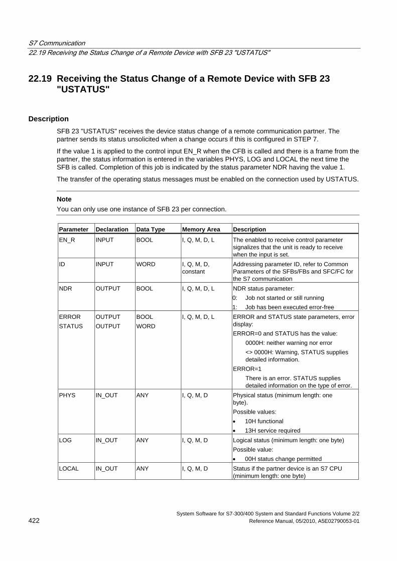
S7 Communication 22.19 Receiving the Status Change of a Remote Device with SFB 23 "USTATUS"
System Software for S7-300/400 System and Standard Functions Volume 2/2 422 Reference Manual, 05/2010, A5E02790053-01
22.19 Receiving the Status Change of a Remote Device with SFB 23 "USTATUS"
Description SFB 23 "USTATUS" receives the device status change of a remote communication partner. The partner sends its status unsolicited when a change occurs if this is configured in STEP 7.
If the value 1 is applied to the control input EN_R when the CFB is called and there is a frame from the partner, the status information is entered in the variables PHYS, LOG and LOCAL the next time the SFB is called. Completion of this job is indicated by the status parameter NDR having the value 1.
The transfer of the operating status messages must be enabled on the connection used by USTATUS.
Note You can only use one instance of SFB 23 per connection. Parameter Declaration Data Type Memory Area Description
EN_R INPUT BOOL I, Q, M, D, L The enabled to receive control parameter signalizes that the unit is ready to receive when the input is set.
ID INPUT WORD I, Q, M, D, constant
Addressing parameter ID, refer to Common Parameters of the SFBs/FBs and SFC/FC for the S7 communication
NDR OUTPUT BOOL I, Q, M, D, L NDR status parameter: 0: Job not started or still running 1: Job has been executed error-free
ERROR STATUS
OUTPUT OUTPUT
BOOL WORD
I, Q, M, D, L ERROR and STATUS state parameters, error display: ERROR=0 and STATUS has the value:
0000H: neither warning nor error <> 0000H: Warning, STATUS supplies detailed information.
ERROR=1 There is an error. STATUS supplies detailed information on the type of error.
PHYS IN_OUT ANY I, Q, M, D Physical status (minimum length: one byte). Possible values: • 10H functional • 13H service required
LOG IN_OUT ANY I, Q, M, D Logical status (minimum length: one byte) Possible value: • 00H status change permitted
LOCAL IN_OUT ANY I, Q, M, D Status if the partner device is an S7 CPU (minimum length: one byte)
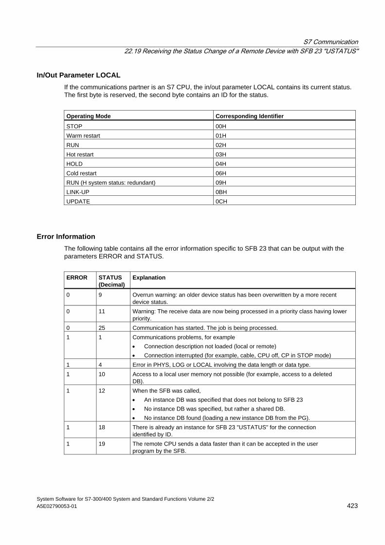
S7 Communication 22.19 Receiving the Status Change of a Remote Device with SFB 23 "USTATUS"
System Software for S7-300/400 System and Standard Functions Volume 2/2 A5E02790053-01 423
In/Out Parameter LOCAL If the communications partner is an S7 CPU, the in/out parameter LOCAL contains its current status. The first byte is reserved, the second byte contains an ID for the status.
Operating Mode Corresponding Identifier
STOP 00H Warm restart 01H RUN 02H Hot restart 03H HOLD 04H Cold restart 06H RUN (H system status: redundant) 09H LINK-UP 0BH UPDATE 0CH
Error Information The following table contains all the error information specific to SFB 23 that can be output with the parameters ERROR and STATUS.
ERROR
STATUS (Decimal)
Explanation
0 9 Overrun warning: an older device status has been overwritten by a more recent device status.
0 11 Warning: The receive data are now being processed in a priority class having lower priority.
0 25 Communication has started. The job is being processed. 1 1 Communications problems, for example
• Connection description not loaded (local or remote) • Connection interrupted (for example, cable, CPU off, CP in STOP mode)
1 4 Error in PHYS, LOG or LOCAL involving the data length or data type. 1 10 Access to a local user memory not possible (for example, access to a deleted
DB). 1 12 When the SFB was called,
• An instance DB was specified that does not belong to SFB 23 • No instance DB was specified, but rather a shared DB. • No instance DB found (loading a new instance DB from the PG).
1 18 There is already an instance for SFB 23 "USTATUS" for the connection identified by ID.
1 19 The remote CPU sends a data faster than it can be accepted in the user program by the SFB.
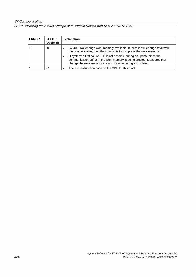
S7 Communication 22.19 Receiving the Status Change of a Remote Device with SFB 23 "USTATUS"
System Software for S7-300/400 System and Standard Functions Volume 2/2 424 Reference Manual, 05/2010, A5E02790053-01
ERROR
STATUS (Decimal)
Explanation
1 20 • S7-400: Not enough work memory available. If there is still enough total work memory available, then the solution is to compress the work memory.
• H system: a first call of SFB is not possible during an update since the communication buffer in the work memory is being created. Measures that change the work memory are not possible during an update.
1 27 • There is no function code on the CPU for this block.
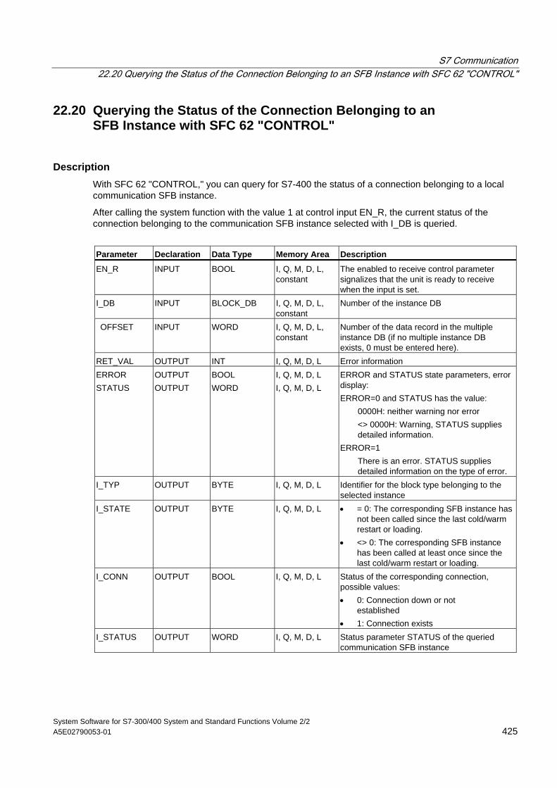
S7 Communication 22.20 Querying the Status of the Connection Belonging to an SFB Instance with SFC 62 "CONTROL"
System Software for S7-300/400 System and Standard Functions Volume 2/2 A5E02790053-01 425
22.20 Querying the Status of the Connection Belonging to an SFB Instance with SFC 62 "CONTROL"
Description With SFC 62 "CONTROL," you can query for S7-400 the status of a connection belonging to a local communication SFB instance.
After calling the system function with the value 1 at control input EN_R, the current status of the connection belonging to the communication SFB instance selected with I_DB is queried.
Parameter Declaration Data Type Memory Area Description
EN_R INPUT BOOL I, Q, M, D, L, constant
The enabled to receive control parameter signalizes that the unit is ready to receive when the input is set.
I_DB INPUT BLOCK_DB I, Q, M, D, L, constant
Number of the instance DB
OFFSET INPUT WORD I, Q, M, D, L, constant
Number of the data record in the multiple instance DB (if no multiple instance DB exists, 0 must be entered here).
RET_VAL OUTPUT INT I, Q, M, D, L Error information ERROR STATUS
OUTPUT OUTPUT
BOOL WORD
I, Q, M, D, L I, Q, M, D, L
ERROR and STATUS state parameters, error display: ERROR=0 and STATUS has the value:
0000H: neither warning nor error <> 0000H: Warning, STATUS supplies detailed information.
ERROR=1 There is an error. STATUS supplies detailed information on the type of error.
I_TYP OUTPUT BYTE I, Q, M, D, L Identifier for the block type belonging to the selected instance
I_STATE OUTPUT BYTE I, Q, M, D, L • = 0: The corresponding SFB instance has not been called since the last cold/warm restart or loading.
• <> 0: The corresponding SFB instance has been called at least once since the last cold/warm restart or loading.
I_CONN OUTPUT BOOL I, Q, M, D, L Status of the corresponding connection, possible values: • 0: Connection down or not
established • 1: Connection exists
I_STATUS OUTPUT WORD I, Q, M, D, L Status parameter STATUS of the queried communication SFB instance
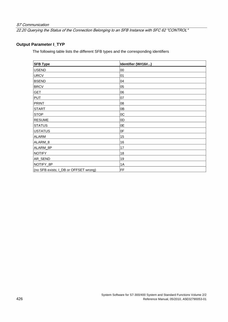
S7 Communication 22.20 Querying the Status of the Connection Belonging to an SFB Instance with SFC 62 "CONTROL"
System Software for S7-300/400 System and Standard Functions Volume 2/2 426 Reference Manual, 05/2010, A5E02790053-01
Output Parameter I_TYP The following table lists the different SFB types and the corresponding identifiers
SFB Type Identifier (W#16#...)
USEND 00 URCV 01 BSEND 04 BRCV 05 GET 06 PUT 07 PRINT 08 START 0B STOP 0C RESUME 0D STATUS 0E USTATUS 0F ALARM 15 ALARM_8 16 ALARM_8P 17 NOTIFY 18 AR_SEND 19 NOTIFY_8P 1A (no SFB exists; I_DB or OFFSET wrong) FF
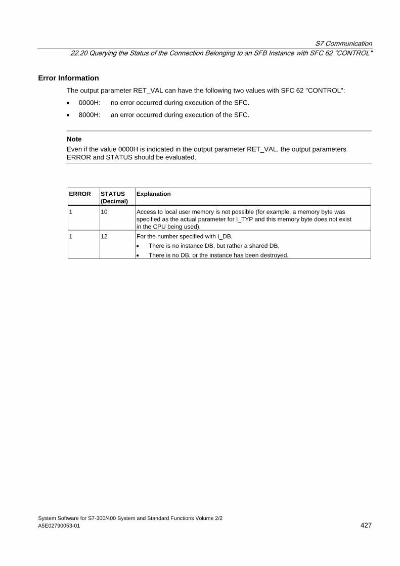
S7 Communication 22.20 Querying the Status of the Connection Belonging to an SFB Instance with SFC 62 "CONTROL"
System Software for S7-300/400 System and Standard Functions Volume 2/2 A5E02790053-01 427
Error Information The output parameter RET_VAL can have the following two values with SFC 62 "CONTROL":
• 0000H: no error occurred during execution of the SFC.
• 8000H: an error occurred during execution of the SFC.
Note
Even if the value 0000H is indicated in the output parameter RET_VAL, the output parameters ERROR and STATUS should be evaluated.
ERROR
STATUS (Decimal)
Explanation
1 10 Access to local user memory is not possible (for example, a memory byte was specified as the actual parameter for I_TYP and this memory byte does not exist in the CPU being used).
1 12 For the number specified with I_DB, • There is no instance DB, but rather a shared DB, • There is no DB, or the instance has been destroyed.
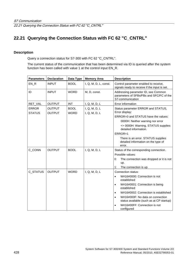
S7 Communication 22.21 Querying the Connection Status with FC 62 "C_CNTRL"
System Software for S7-300/400 System and Standard Functions Volume 2/2 428 Reference Manual, 05/2010, A5E02790053-01
22.21 Querying the Connection Status with FC 62 "C_CNTRL"
Description Query a connection status for S7-300 with FC 62 "C_CNTRL".
The current status of the communication that has been determined via ID is queried after the system function has been called with value 1 at the control input EN_R.
Parameters Declaration Data Type Memory Area Description
EN_R INPUT BOOL I, Q, M, D, L, const. Control parameter enabled to receive, signals ready to receive if the input is set.
ID INPUT WORD M, D, const. Addressing parameter ID, see Common parameters of SFBs/FBs and SFC/FC of the S7-communication
RET_VAL OUTPUT INT I, Q, M, D, L Error information ERROR STATUS
OUTPUT OUTPUT
BOOL WORD
I, Q, M, D, L I, Q, M, D, L
Status parameter ERROR and STATUS, Error display: ERROR=0 and STATUS have the values:
0000H: Neither warning nor error <> 0000H: Warning, STATUS supplies
detailed information. ERROR=1
There is an error. STATUS supplies detailed information on the type of error.
C_CONN OUTPUT BOOL I, Q, M, D, L Status of the corresponding connection. Possible values: 0: The connection was dropped or it is not
up. 1: The connection is up.
C_STATUS OUTPUT WORD I, Q, M, D, L Connection status: • W#16#0000: Connection is not
established • W#16#0001: Connection is being
established • W#16#0002: Connection is established • W#16#000F: No data on connection
status available (such as at CP startup) • W#16#00FF: Connection is not
configured
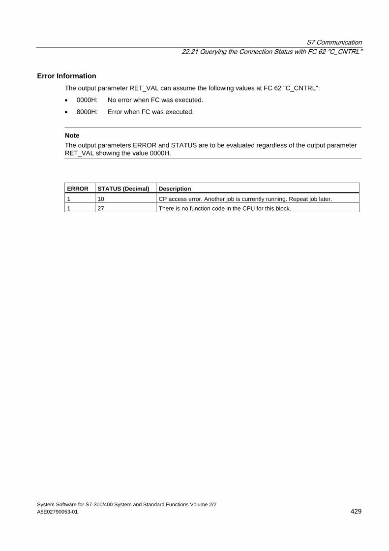
S7 Communication 22.21 Querying the Connection Status with FC 62 "C_CNTRL"
System Software for S7-300/400 System and Standard Functions Volume 2/2 A5E02790053-01 429
Error Information The output parameter RET_VAL can assume the following values at FC 62 "C_CNTRL":
• 0000H: No error when FC was executed.
• 8000H: Error when FC was executed.
Note
The output parameters ERROR and STATUS are to be evaluated regardless of the output parameter RET_VAL showing the value 0000H.
ERROR STATUS (Decimal) Description
1 10 CP access error. Another job is currently running. Repeat job later. 1 27 There is no function code in the CPU for this block.

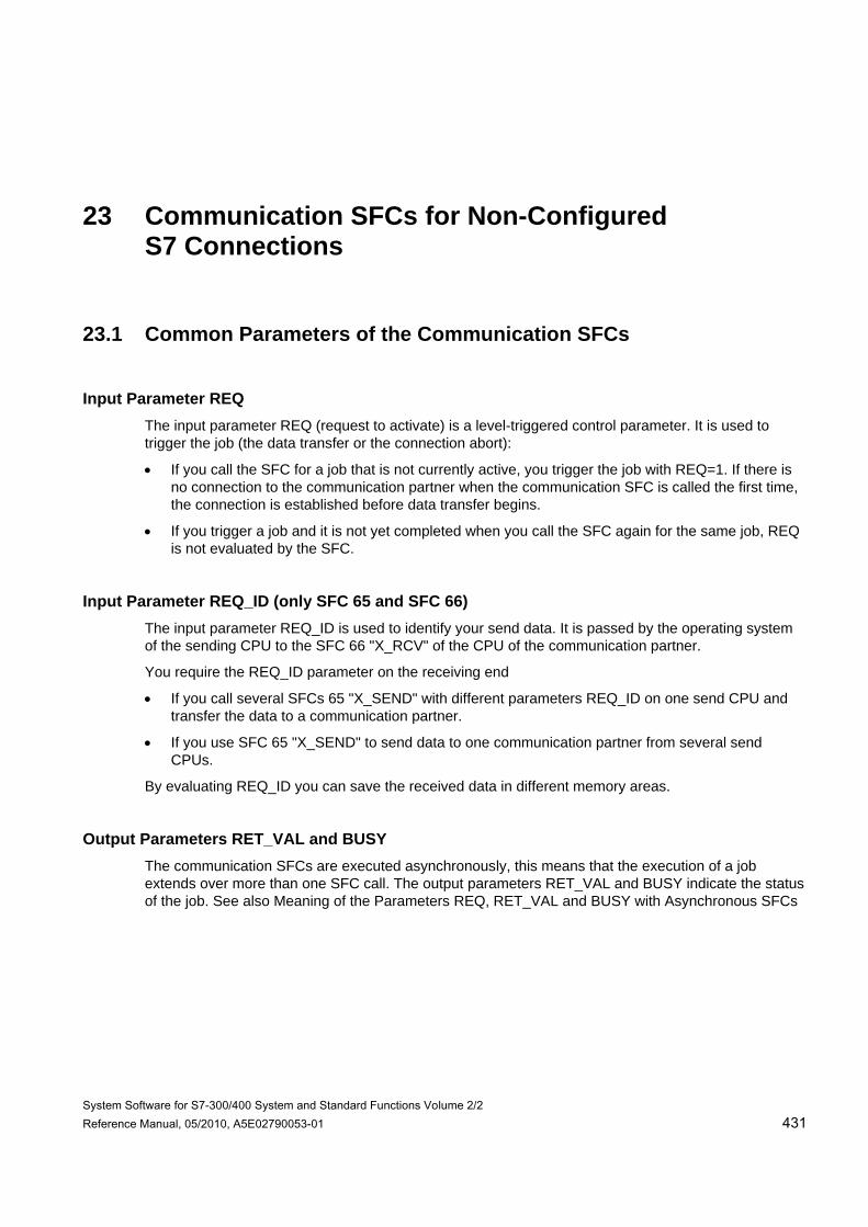
System Software for S7-300/400 System and Standard Functions Volume 2/2 Reference Manual, 05/2010, A5E02790053-01 431
23 Communication SFCs for Non-Configured S7 Connections
23.1 Common Parameters of the Communication SFCs
Input Parameter REQ The input parameter REQ (request to activate) is a level-triggered control parameter. It is used to trigger the job (the data transfer or the connection abort):
• If you call the SFC for a job that is not currently active, you trigger the job with REQ=1. If there is no connection to the communication partner when the communication SFC is called the first time, the connection is established before data transfer begins.
• If you trigger a job and it is not yet completed when you call the SFC again for the same job, REQ is not evaluated by the SFC.
Input Parameter REQ_ID (only SFC 65 and SFC 66) The input parameter REQ_ID is used to identify your send data. It is passed by the operating system of the sending CPU to the SFC 66 "X_RCV" of the CPU of the communication partner.
You require the REQ_ID parameter on the receiving end
• If you call several SFCs 65 "X_SEND" with different parameters REQ_ID on one send CPU and transfer the data to a communication partner.
• If you use SFC 65 "X_SEND" to send data to one communication partner from several send CPUs.
By evaluating REQ_ID you can save the received data in different memory areas.
Output Parameters RET_VAL and BUSY The communication SFCs are executed asynchronously, this means that the execution of a job extends over more than one SFC call. The output parameters RET_VAL and BUSY indicate the status of the job. See also Meaning of the Parameters REQ, RET_VAL and BUSY with Asynchronous SFCs
Communication SFCs for Non-Configured S7 Connections 23.1 Common Parameters of the Communication SFCs
System Software for S7-300/400 System and Standard Functions Volume 2/2 432 Reference Manual, 05/2010, A5E02790053-01
Input Parameter CONT The input parameter CONT (continue) is a control parameter. Using this parameter, you decide whether or not a connection to the communication partner remains established after the job is completed.
• If you select CONT=0 at the first call, the connection is terminated again after the data transfer is completed. The connection is then available again for data exchange with a new communication partner.
This method ensures that connection resources are only occupied when they are actually in use.
• If you select CONT=1 at the first call, the connection remains established on completion of the data transfer.
This method is, for example, useful when you exchange data cyclically between two stations.
Note
A connection established with CONT=1 can be terminated explicitly with SFC 69 "X_ABORT" or with SFC 74 "I_ABORT."
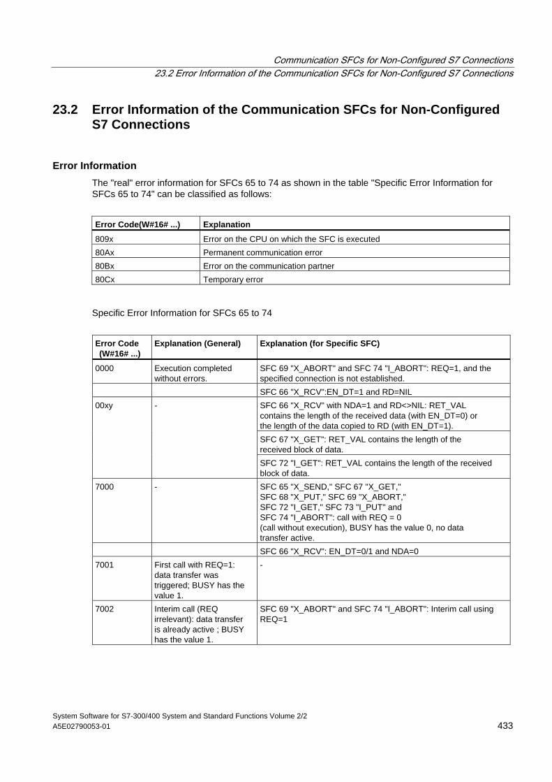
Communication SFCs for Non-Configured S7 Connections 23.2 Error Information of the Communication SFCs for Non-Configured S7 Connections
System Software for S7-300/400 System and Standard Functions Volume 2/2 A5E02790053-01 433
23.2 Error Information of the Communication SFCs for Non-Configured S7 Connections
Error Information The "real" error information for SFCs 65 to 74 as shown in the table "Specific Error Information for SFCs 65 to 74" can be classified as follows:
Error Code(W#16# ...) Explanation
809x Error on the CPU on which the SFC is executed 80Ax Permanent communication error 80Bx Error on the communication partner 80Cx Temporary error
Specific Error Information for SFCs 65 to 74
Error Code (W#16# ...)
Explanation (General)
Explanation (for Specific SFC)
0000 Execution completed without errors.
SFC 69 "X_ABORT" and SFC 74 "I_ABORT": REQ=1, and the specified connection is not established.
SFC 66 "X_RCV":EN_DT=1 and RD=NIL SFC 66 "X_RCV" with NDA=1 and RD<>NIL: RET_VAL contains the length of the received data (with EN_DT=0) or the length of the data copied to RD (with EN_DT=1). SFC 67 "X_GET": RET_VAL contains the length of the received block of data.
00xy -
SFC 72 "I_GET": RET_VAL contains the length of the received block of data.
7000 - SFC 65 "X_SEND," SFC 67 "X_GET," SFC 68 "X_PUT," SFC 69 "X_ABORT," SFC 72 "I_GET," SFC 73 "I_PUT" and SFC 74 "I_ABORT": call with REQ = 0 (call without execution), BUSY has the value 0, no data transfer active.
SFC 66 "X_RCV": EN_DT=0/1 and NDA=0 7001 First call with REQ=1:
data transfer was triggered; BUSY has the value 1.
-
7002 Interim call (REQ irrelevant): data transfer is already active ; BUSY has the value 1.
SFC 69 "X_ABORT" and SFC 74 "I_ABORT": Interim call using REQ=1
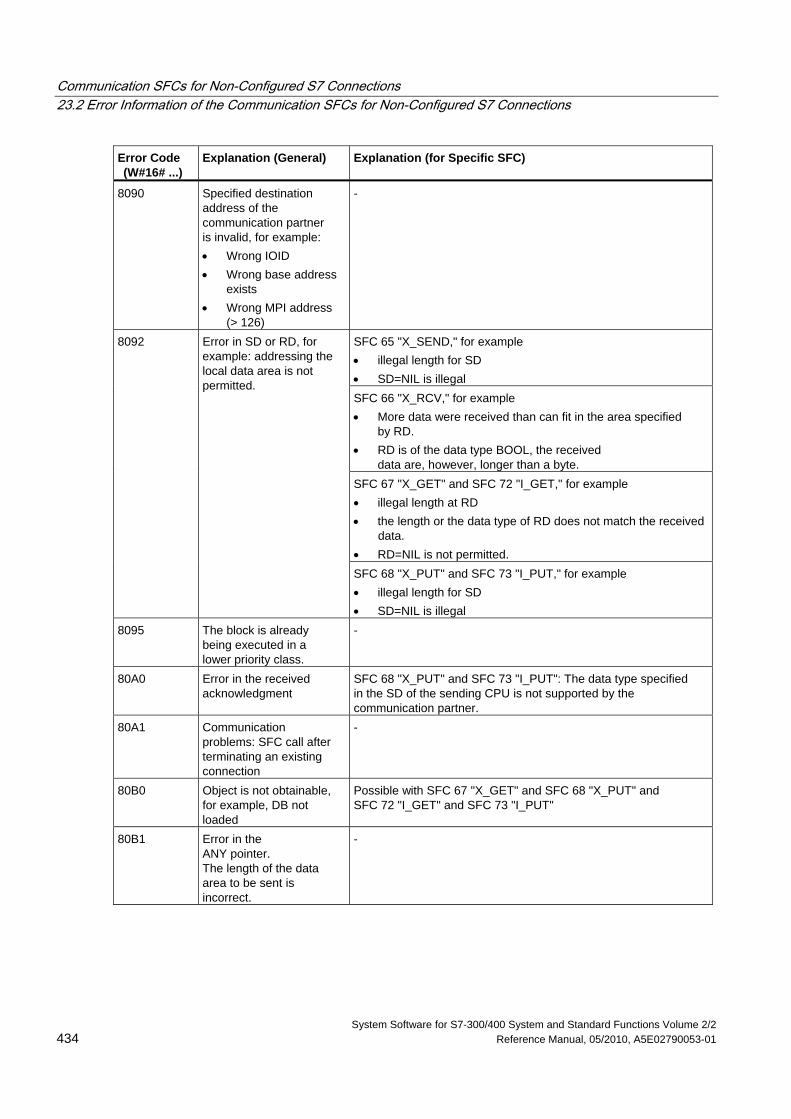
Communication SFCs for Non-Configured S7 Connections 23.2 Error Information of the Communication SFCs for Non-Configured S7 Connections
System Software for S7-300/400 System and Standard Functions Volume 2/2 434 Reference Manual, 05/2010, A5E02790053-01
Error Code (W#16# ...)
Explanation (General)
Explanation (for Specific SFC)
8090 Specified destination address of the communication partner is invalid, for example: • Wrong IOID • Wrong base address
exists • Wrong MPI address
(> 126)
-
SFC 65 "X_SEND," for example • illegal length for SD • SD=NIL is illegal SFC 66 "X_RCV," for example • More data were received than can fit in the area specified
by RD. • RD is of the data type BOOL, the received
data are, however, longer than a byte. SFC 67 "X_GET" and SFC 72 "I_GET," for example • illegal length at RD • the length or the data type of RD does not match the received
data. • RD=NIL is not permitted.
8092 Error in SD or RD, for example: addressing the local data area is not permitted.
SFC 68 "X_PUT" and SFC 73 "I_PUT," for example • illegal length for SD • SD=NIL is illegal
8095 The block is already being executed in a lower priority class.
-
80A0 Error in the received acknowledgment
SFC 68 "X_PUT" and SFC 73 "I_PUT": The data type specified in the SD of the sending CPU is not supported by the communication partner.
80A1 Communication problems: SFC call after terminating an existing connection
-
80B0 Object is not obtainable, for example, DB not loaded
Possible with SFC 67 "X_GET" and SFC 68 "X_PUT" and SFC 72 "I_GET" and SFC 73 "I_PUT"
80B1 Error in the ANY pointer. The length of the data area to be sent is incorrect.
-
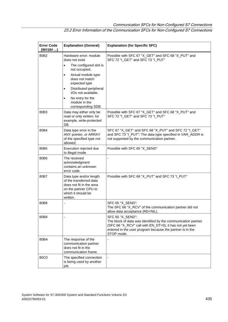
Communication SFCs for Non-Configured S7 Connections 23.2 Error Information of the Communication SFCs for Non-Configured S7 Connections
System Software for S7-300/400 System and Standard Functions Volume 2/2 A5E02790053-01 435
Error Code (W#16# ...)
Explanation (General)
Explanation (for Specific SFC)
80B2 Hardware error: module does not exist • The configured slot is
not occupied. • Actual module type
does not match expected type
• Distributed peripheral I/Os not available.
• No entry for the module in the corresponding SDB.
Possible with SFC 67 "X_GET" and SFC 68 "X_PUT" and SFC 72 "I_GET" and SFC 73 "I_PUT"
80B3 Data may either only be read or only written, for example, write-protected DB
Possible with SFC 67 "X_GET" and SFC 68 "X_PUT" and SFC 72 "I_GET" and SFC 73 "I_PUT"
80B4 Data type error in the ANY pointer, or ARRAY of the specified type not allowed.
SFC 67 "X_GET" and SFC 68 "X_PUT" and SFC 72 "I_GET" and SFC 73 "I_PUT": The data type specified in VAR_ADDR is not supported by the communication partner.
80B5 Execution rejected due to illegal mode
Possible with SFC 65 "X_SEND"
80B6 The received acknowledgment contains an unknown error code.
-
80B7 Data type and/or length of the transferred data does not fit in the area on the partner CPU to which it should be written.
Possible with SFC 68 "X_PUT" and SFC 73 "I_PUT"
80B8 - SFC 65 "X_SEND": The SFC 66 "X_RCV" of the communication partner did not allow data acceptance (RD=NIL).
80B9 - SFC 65 "X_SEND": The block of data was identified by the communication partner (SFC 66 "X_RCV" call with EN_DT=0), it has not yet been entered in the user program because the partner is in the STOP mode.
80BA The response of the communication partner does not fit in the communication frame.
-
80C0 The specified connection is being used by another job.
-
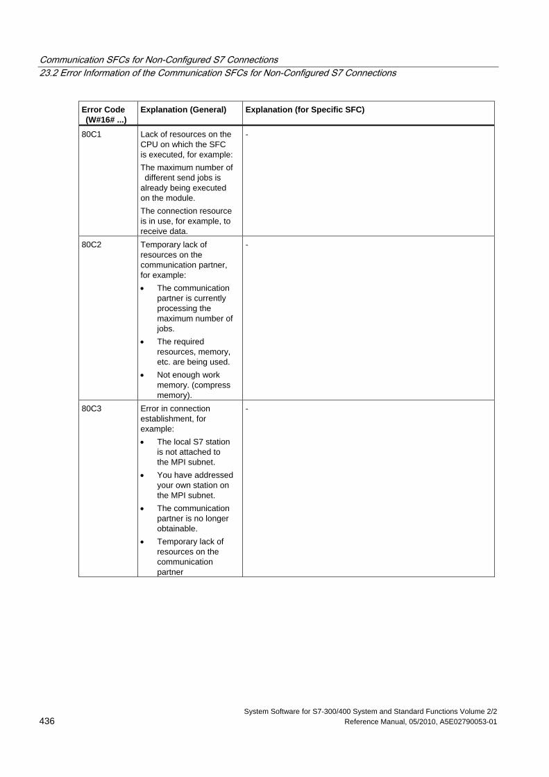
Communication SFCs for Non-Configured S7 Connections 23.2 Error Information of the Communication SFCs for Non-Configured S7 Connections
System Software for S7-300/400 System and Standard Functions Volume 2/2 436 Reference Manual, 05/2010, A5E02790053-01
Error Code (W#16# ...)
Explanation (General)
Explanation (for Specific SFC)
80C1 Lack of resources on the CPU on which the SFC is executed, for example: The maximum number of different send jobs is already being executed on the module. The connection resource is in use, for example, to receive data.
-
80C2 Temporary lack of resources on the communication partner, for example: • The communication
partner is currently processing the maximum number of jobs.
• The required resources, memory, etc. are being used.
• Not enough work memory. (compress memory).
-
80C3 Error in connection establishment, for example: • The local S7 station
is not attached to the MPI subnet.
• You have addressed your own station on the MPI subnet.
• The communication partner is no longer obtainable.
• Temporary lack of resources on the communication partner
-
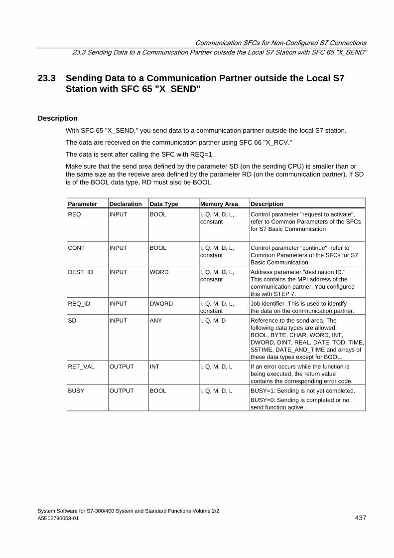
Communication SFCs for Non-Configured S7 Connections 23.3 Sending Data to a Communication Partner outside the Local S7 Station with SFC 65 "X_SEND"
System Software for S7-300/400 System and Standard Functions Volume 2/2 A5E02790053-01 437
23.3 Sending Data to a Communication Partner outside the Local S7 Station with SFC 65 "X_SEND"
Description With SFC 65 "X_SEND," you send data to a communication partner outside the local S7 station.
The data are received on the communication partner using SFC 66 "X_RCV."
The data is sent after calling the SFC with REQ=1.
Make sure that the send area defined by the parameter SD (on the sending CPU) is smaller than or the same size as the receive area defined by the parameter RD (on the communication partner). If SD is of the BOOL data type, RD must also be BOOL.
Parameter Declaration Data Type Memory Area Description
REQ INPUT BOOL I, Q, M, D, L, constant
Control parameter "request to activate", refer to Common Parameters of the SFCs for S7 Basic Communication
CONT INPUT BOOL I, Q, M, D, L, constant
Control parameter "continue", refer to Common Parameters of the SFCs for S7 Basic Communication
DEST_ID INPUT WORD I, Q, M, D, L, constant
Address parameter "destination ID." This contains the MPI address of the communication partner. You configured this with STEP 7.
REQ_ID INPUT DWORD I, Q, M, D, L, constant
Job identifier. This is used to identify the data on the communication partner.
SD INPUT ANY I, Q, M, D Reference to the send area. The following data types are allowed: BOOL, BYTE, CHAR, WORD, INT, DWORD, DINT, REAL, DATE, TOD, TIME, S5TIME, DATE_AND_TIME and arrays of these data types except for BOOL.
RET_VAL OUTPUT INT I, Q, M, D, L If an error occurs while the function is being executed, the return value contains the corresponding error code.
BUSY OUTPUT BOOL I, Q, M, D, L BUSY=1: Sending is not yet completed. BUSY=0: Sending is completed or no send function active.
Communication SFCs for Non-Configured S7 Connections 23.3 Sending Data to a Communication Partner outside the Local S7 Station with SFC 65 "X_SEND"
System Software for S7-300/400 System and Standard Functions Volume 2/2 438 Reference Manual, 05/2010, A5E02790053-01
Data Consistency The data are sent in a consistent state.
Error Information See Error Information of the Communication SFCs for Non-Configured S7 Connections and Evaluating Errors with the Output Parameter RET_VAL
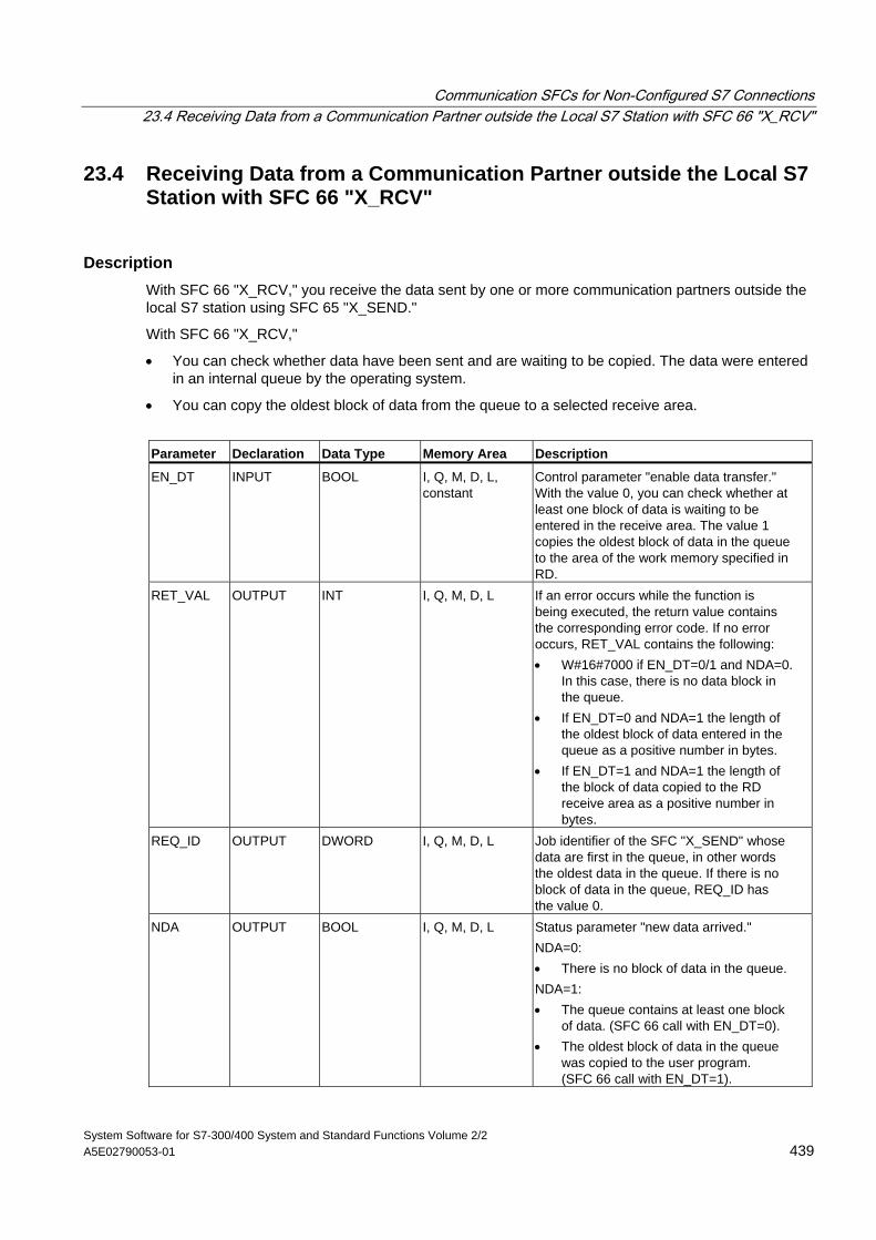
Communication SFCs for Non-Configured S7 Connections 23.4 Receiving Data from a Communication Partner outside the Local S7 Station with SFC 66 "X_RCV"
System Software for S7-300/400 System and Standard Functions Volume 2/2 A5E02790053-01 439
23.4 Receiving Data from a Communication Partner outside the Local S7 Station with SFC 66 "X_RCV"
Description With SFC 66 "X_RCV," you receive the data sent by one or more communication partners outside the local S7 station using SFC 65 "X_SEND."
With SFC 66 "X_RCV,"
• You can check whether data have been sent and are waiting to be copied. The data were entered in an internal queue by the operating system.
• You can copy the oldest block of data from the queue to a selected receive area.
Parameter Declaration Data Type Memory Area Description
EN_DT INPUT BOOL I, Q, M, D, L, constant
Control parameter "enable data transfer." With the value 0, you can check whether at least one block of data is waiting to be entered in the receive area. The value 1 copies the oldest block of data in the queue to the area of the work memory specified in RD.
RET_VAL OUTPUT INT I, Q, M, D, L If an error occurs while the function is being executed, the return value contains the corresponding error code. If no error occurs, RET_VAL contains the following: • W#16#7000 if EN_DT=0/1 and NDA=0.
In this case, there is no data block in the queue.
• If EN_DT=0 and NDA=1 the length of the oldest block of data entered in the queue as a positive number in bytes.
• If EN_DT=1 and NDA=1 the length of the block of data copied to the RD receive area as a positive number in bytes.
REQ_ID OUTPUT DWORD I, Q, M, D, L Job identifier of the SFC "X_SEND" whose data are first in the queue, in other words the oldest data in the queue. If there is no block of data in the queue, REQ_ID has the value 0.
NDA OUTPUT BOOL I, Q, M, D, L Status parameter "new data arrived." NDA=0: • There is no block of data in the queue. NDA=1: • The queue contains at least one block
of data. (SFC 66 call with EN_DT=0). • The oldest block of data in the queue
was copied to the user program. (SFC 66 call with EN_DT=1).
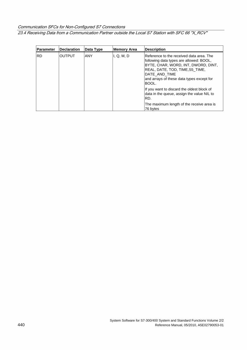
Communication SFCs for Non-Configured S7 Connections 23.4 Receiving Data from a Communication Partner outside the Local S7 Station with SFC 66 "X_RCV"
System Software for S7-300/400 System and Standard Functions Volume 2/2 440 Reference Manual, 05/2010, A5E02790053-01
Parameter Declaration Data Type Memory Area Description
RD OUTPUT ANY I, Q, M, D Reference to the received data area. The following data types are allowed: BOOL, BYTE, CHAR, WORD, INT, DWORD, DINT, REAL, DATE, TOD, TIME,S5_TIME, DATE_AND_TIME and arrays of these data types except for BOOL. If you want to discard the oldest block of data in the queue, assign the value NIL to RD. The maximum length of the receive area is 76 bytes
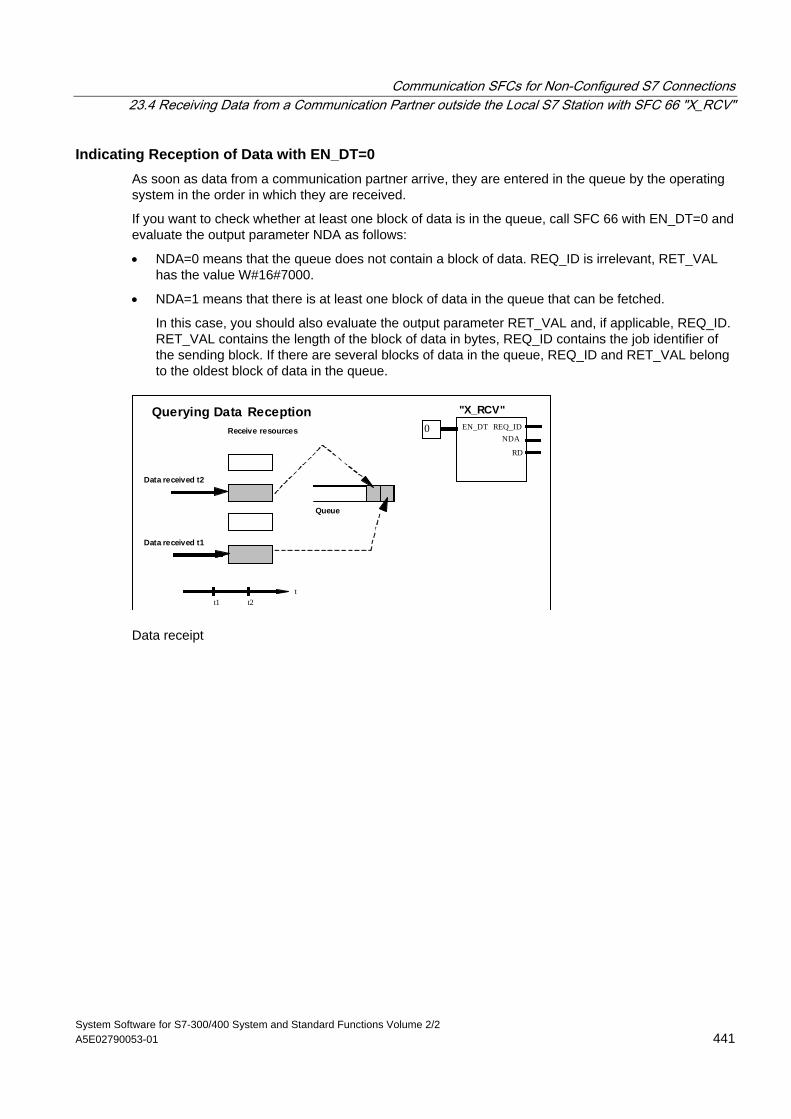
Communication SFCs for Non-Configured S7 Connections 23.4 Receiving Data from a Communication Partner outside the Local S7 Station with SFC 66 "X_RCV"
System Software for S7-300/400 System and Standard Functions Volume 2/2 A5E02790053-01 441
Indicating Reception of Data with EN_DT=0 As soon as data from a communication partner arrive, they are entered in the queue by the operating system in the order in which they are received.
If you want to check whether at least one block of data is in the queue, call SFC 66 with EN_DT=0 and evaluate the output parameter NDA as follows:
• NDA=0 means that the queue does not contain a block of data. REQ_ID is irrelevant, RET_VAL has the value W#16#7000.
• NDA=1 means that there is at least one block of data in the queue that can be fetched.
In this case, you should also evaluate the output parameter RET_VAL and, if applicable, REQ_ID. RET_VAL contains the length of the block of data in bytes, REQ_ID contains the job identifier of the sending block. If there are several blocks of data in the queue, REQ_ID and RET_VAL belong to the oldest block of data in the queue.
Data received t2
Receive resources
Data received t1
t1 t2t
Queue
REQ_ID
RD
EN_DT
"X_RCV"
NDA0
Querying Data Reception
Data receipt
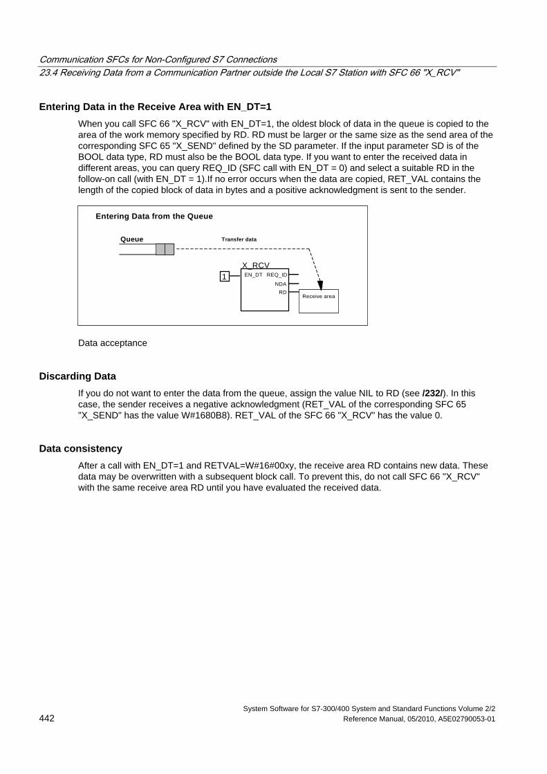
Communication SFCs for Non-Configured S7 Connections 23.4 Receiving Data from a Communication Partner outside the Local S7 Station with SFC 66 "X_RCV"
System Software for S7-300/400 System and Standard Functions Volume 2/2 442 Reference Manual, 05/2010, A5E02790053-01
Entering Data in the Receive Area with EN_DT=1 When you call SFC 66 "X_RCV" with EN_DT=1, the oldest block of data in the queue is copied to the area of the work memory specified by RD. RD must be larger or the same size as the send area of the corresponding SFC 65 "X_SEND" defined by the SD parameter. If the input parameter SD is of the BOOL data type, RD must also be the BOOL data type. If you want to enter the received data in different areas, you can query REQ_ID (SFC call with EN_DT = 0) and select a suitable RD in the follow-on call (with EN_DT = 1).If no error occurs when the data are copied, RET_VAL contains the length of the copied block of data in bytes and a positive acknowledgment is sent to the sender.
EN_DT REQ_IDX_RCV
NDARD
Queue
Receive area
Transfer data
1
Entering Data from the Queue
Data acceptance
Discarding Data If you do not want to enter the data from the queue, assign the value NIL to RD (see /232/). In this case, the sender receives a negative acknowledgment (RET_VAL of the corresponding SFC 65 "X_SEND" has the value W#1680B8). RET_VAL of the SFC 66 "X_RCV" has the value 0.
Data consistency After a call with EN_DT=1 and RETVAL=W#16#00xy, the receive area RD contains new data. These data may be overwritten with a subsequent block call. To prevent this, do not call SFC 66 "X_RCV" with the same receive area RD until you have evaluated the received data.
Communication SFCs for Non-Configured S7 Connections 23.4 Receiving Data from a Communication Partner outside the Local S7 Station with SFC 66 "X_RCV"
System Software for S7-300/400 System and Standard Functions Volume 2/2 A5E02790053-01 443
Changing to the STOP Mode If the CPU changes to the STOP mode
• all newly arriving jobs are acknowledged negatively.
• all jobs that have arrived and are in the queue are acknowledged negatively.
- If the STOP is followed by a warm or cold restart, the blocks of data are all discarded.
- If the STOP is followed by a restart, (not possible on an S7-300 and an S7-400H) the block of data belonging to the oldest job is entered in the user program, if the queue was queried before the change to the STOP mode (by calling SFC 66 "X_RCV" with EN_DT=0). Otherwise it is discarded.
All other blocks of data are discarded.
Connection Abort If the connection is terminated a job belonging to the connection that is already in the queue is discarded.
Exception: If this job is the oldest in the queue, and you have already detected its presence by calling SFC 66 "X_RCV" with EN_DT=0, you can enter it in the receive area with EN_DT=1.
Error Information See Error Information of the Communication SFCs for Non-Configured S7 Connections and Evaluating Errors with the Output Parameter RET_VAL
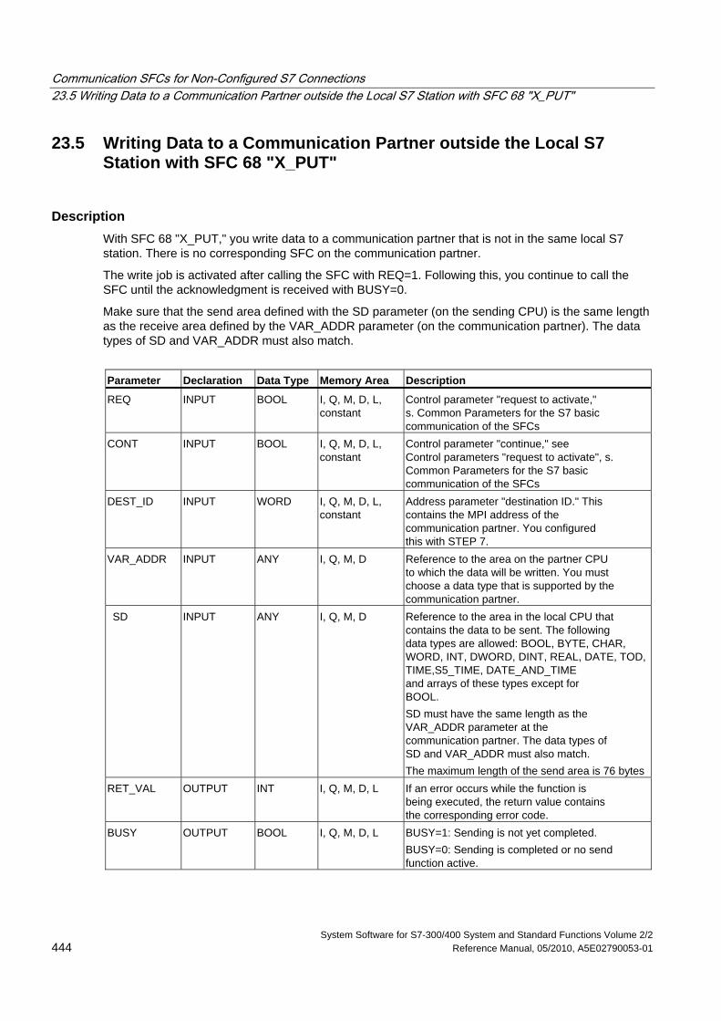
Communication SFCs for Non-Configured S7 Connections 23.5 Writing Data to a Communication Partner outside the Local S7 Station with SFC 68 "X_PUT"
System Software for S7-300/400 System and Standard Functions Volume 2/2 444 Reference Manual, 05/2010, A5E02790053-01
23.5 Writing Data to a Communication Partner outside the Local S7 Station with SFC 68 "X_PUT"
Description With SFC 68 "X_PUT," you write data to a communication partner that is not in the same local S7 station. There is no corresponding SFC on the communication partner.
The write job is activated after calling the SFC with REQ=1. Following this, you continue to call the SFC until the acknowledgment is received with BUSY=0.
Make sure that the send area defined with the SD parameter (on the sending CPU) is the same length as the receive area defined by the VAR_ADDR parameter (on the communication partner). The data types of SD and VAR_ADDR must also match.
Parameter Declaration Data Type Memory Area Description
REQ INPUT BOOL I, Q, M, D, L, constant
Control parameter "request to activate," s. Common Parameters for the S7 basic communication of the SFCs
CONT INPUT BOOL I, Q, M, D, L, constant
Control parameter "continue," see Control parameters "request to activate", s. Common Parameters for the S7 basic communication of the SFCs
DEST_ID INPUT WORD I, Q, M, D, L, constant
Address parameter "destination ID." This contains the MPI address of the communication partner. You configured this with STEP 7.
VAR_ADDR INPUT ANY I, Q, M, D Reference to the area on the partner CPU to which the data will be written. You must choose a data type that is supported by the communication partner.
SD INPUT ANY I, Q, M, D Reference to the area in the local CPU that contains the data to be sent. The following data types are allowed: BOOL, BYTE, CHAR, WORD, INT, DWORD, DINT, REAL, DATE, TOD, TIME,S5_TIME, DATE_AND_TIME and arrays of these types except for BOOL. SD must have the same length as the VAR_ADDR parameter at the communication partner. The data types of SD and VAR_ADDR must also match. The maximum length of the send area is 76 bytes
RET_VAL OUTPUT INT I, Q, M, D, L If an error occurs while the function is being executed, the return value contains the corresponding error code.
BUSY OUTPUT BOOL I, Q, M, D, L BUSY=1: Sending is not yet completed. BUSY=0: Sending is completed or no send function active.
Communication SFCs for Non-Configured S7 Connections 23.5 Writing Data to a Communication Partner outside the Local S7 Station with SFC 68 "X_PUT"
System Software for S7-300/400 System and Standard Functions Volume 2/2 A5E02790053-01 445
Changing to the STOP Mode If the CPU changes to the STOP mode, the connection established by SFC 68 "X_PUT" is terminated. Data can no longer be sent. If the send data have already been copied to the internal buffer when the CPU changes mode, the contents of the buffer are discarded.
Communication Partner Changes to the STOP Mode If the CPU of the communication partner changes to the STOP mode, this does not affect the data transfer with SFC 68 "X_PUT." The data can also be written with the partner in the STOP mode.
Data Consistency The data are sent in a consistent state.
Error Information See Error Information of the Communication SFCs for Non-Configured S7 Connections and Evaluating Errors with the Output Parameter RET_VAL
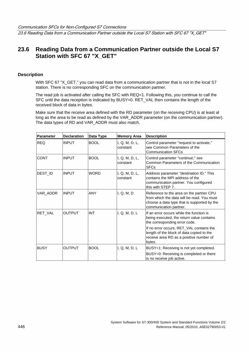
Communication SFCs for Non-Configured S7 Connections 23.6 Reading Data from a Communication Partner outside the Local S7 Station with SFC 67 "X_GET"
System Software for S7-300/400 System and Standard Functions Volume 2/2 446 Reference Manual, 05/2010, A5E02790053-01
23.6 Reading Data from a Communication Partner outside the Local S7 Station with SFC 67 "X_GET"
Description With SFC 67 "X_GET," you can read data from a communication partner that is not in the local S7 station. There is no corresponding SFC on the communication partner.
The read job is activated after calling the SFC with REQ=1. Following this, you continue to call the SFC until the data reception is indicated by BUSY=0. RET_VAL then contains the length of the received block of data in bytes.
Make sure that the receive area defined with the RD parameter (on the receiving CPU) is at least al long as the area to be read as defined by the VAR_ADDR parameter (on the communication partner). The data types of RD and VAR_ADDR must also match.
Parameter Declaration Data Type Memory Area Description
REQ INPUT BOOL I, Q, M, D, L, constant
Control parameter "request to activate," see Common Parameters of the Communication SFCs
CONT INPUT BOOL I, Q, M, D, L, constant
Control parameter "continue," see Common Parameters of the Communication SFCs
DEST_ID INPUT WORD I, Q, M, D, L, constant
Address parameter "destination ID." This contains the MPI address of the communication partner. You configured this with STEP 7.
VAR_ADDR INPUT ANY I, Q, M, D Reference to the area on the partner CPU from which the data will be read. You must choose a data type that is supported by the communication partner.
RET_VAL OUTPUT INT I, Q, M, D, L If an error occurs while the function is being executed, the return value contains the corresponding error code. If no error occurs, RET_VAL contains the length of the block of data copied to the receive area RD as a positive number of bytes.
BUSY OUTPUT BOOL I, Q, M, D, L BUSY=1: Receiving is not yet completed. BUSY=0: Receiving is completed or there is no receive job active.
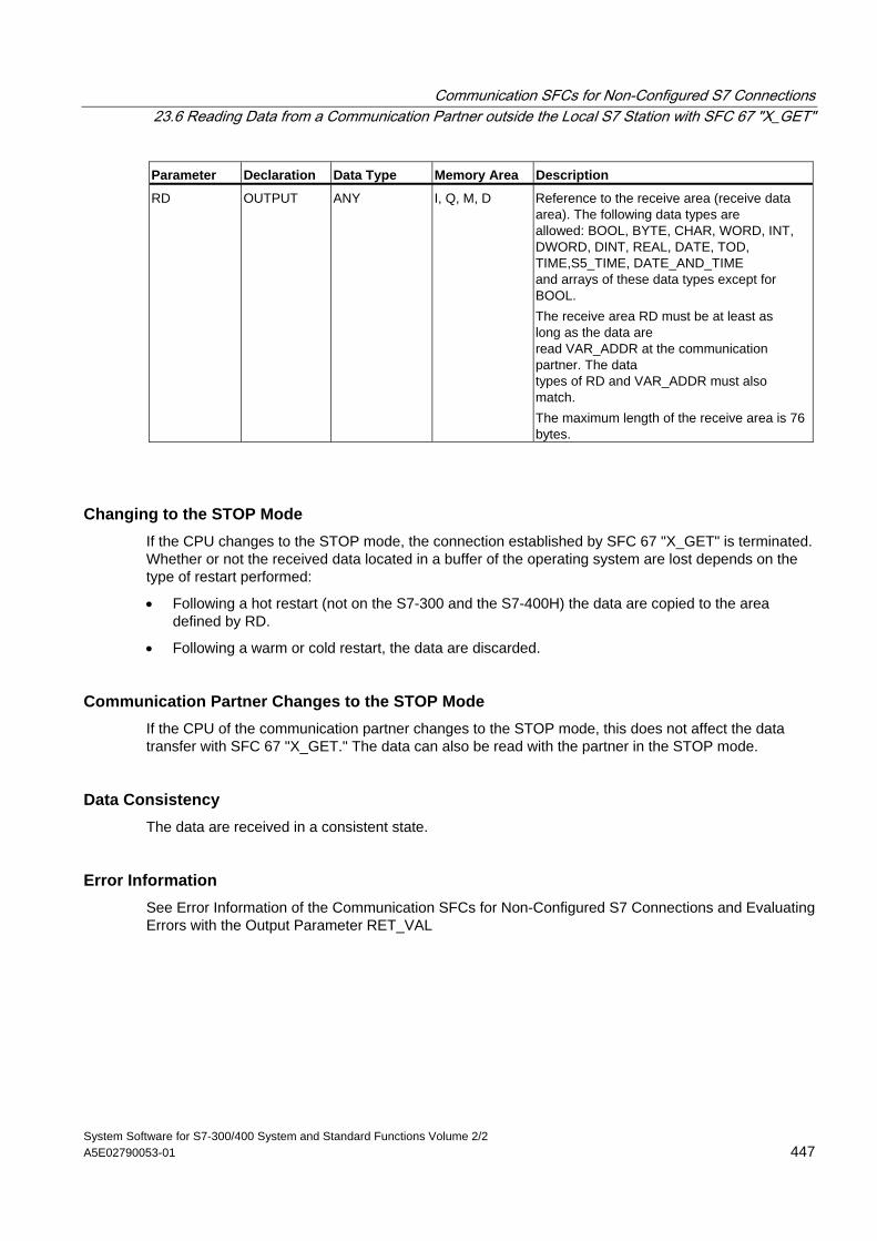
Communication SFCs for Non-Configured S7 Connections 23.6 Reading Data from a Communication Partner outside the Local S7 Station with SFC 67 "X_GET"
System Software for S7-300/400 System and Standard Functions Volume 2/2 A5E02790053-01 447
Parameter Declaration Data Type Memory Area Description
RD OUTPUT ANY I, Q, M, D Reference to the receive area (receive data area). The following data types are allowed: BOOL, BYTE, CHAR, WORD, INT, DWORD, DINT, REAL, DATE, TOD, TIME,S5_TIME, DATE_AND_TIME and arrays of these data types except for BOOL. The receive area RD must be at least as long as the data are read VAR_ADDR at the communication partner. The data types of RD and VAR_ADDR must also match. The maximum length of the receive area is 76 bytes.
Changing to the STOP Mode If the CPU changes to the STOP mode, the connection established by SFC 67 "X_GET" is terminated. Whether or not the received data located in a buffer of the operating system are lost depends on the type of restart performed:
• Following a hot restart (not on the S7-300 and the S7-400H) the data are copied to the area defined by RD.
• Following a warm or cold restart, the data are discarded.
Communication Partner Changes to the STOP Mode If the CPU of the communication partner changes to the STOP mode, this does not affect the data transfer with SFC 67 "X_GET." The data can also be read with the partner in the STOP mode.
Data Consistency The data are received in a consistent state.
Error Information See Error Information of the Communication SFCs for Non-Configured S7 Connections and Evaluating Errors with the Output Parameter RET_VAL
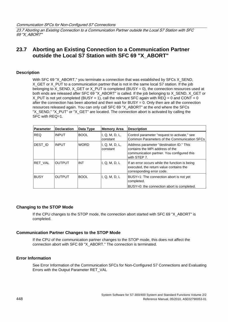
Communication SFCs for Non-Configured S7 Connections 23.7 Aborting an Existing Connection to a Communication Partner outside the Local S7 Station with SFC 69 "X_ABORT"
System Software for S7-300/400 System and Standard Functions Volume 2/2 448 Reference Manual, 05/2010, A5E02790053-01
23.7 Aborting an Existing Connection to a Communication Partner outside the Local S7 Station with SFC 69 "X_ABORT"
Description With SFC 69 "X_ABORT," you terminate a connection that was established by SFCs X_SEND, X_GET or X_PUT to a communication partner that is not in the same local S7 station. If the job belonging to X_SEND, X_GET or X_PUT is completed (BUSY = 0), the connection resources used at both ends are released after SFC 69 "X_ABORT" is called. If the job belonging to X_SEND, X_GET or X_PUT is not yet completed (BUSY = 1), call the relevant SFC again with REQ = 0 and CONT = 0 after the connection has been aborted and then wait for BUSY = 0. Only then are all the connection resources released again. You can only call SFC 69 "X_ABORT" at the end where the SFCs "X_SEND," "X_PUT" or "X_GET" are located. The connection abort is activated by calling the SFC with REQ=1.
Parameter Declaration Data Type Memory Area Description
REQ INPUT BOOL I, Q, M, D, L, constant
Control parameter "request to activate," see Common Parameters of the Communication SFCs
DEST_ID INPUT WORD I, Q, M, D, L, constant
Address parameter "destination ID." This contains the MPI address of the communication partner. You configured this with STEP 7.
RET_VAL OUTPUT INT I, Q, M, D, L If an error occurs while the function is being executed, the return value contains the corresponding error code.
BUSY OUTPUT BOOL I, Q, M, D, L BUSY=1: The connection abort is not yet completed. BUSY=0: the connection abort is completed.
Changing to the STOP Mode If the CPU changes to the STOP mode, the connection abort started with SFC 69 "X_ABORT" is completed.
Communication Partner Changes to the STOP Mode If the CPU of the communication partner changes to the STOP mode, this does not affect the connection abort with SFC 69 "X_ABORT." The connection is terminated.
Error Information See Error Information of the Communication SFCs for Non-Configured S7 Connections and Evaluating Errors with the Output Parameter RET_VAL
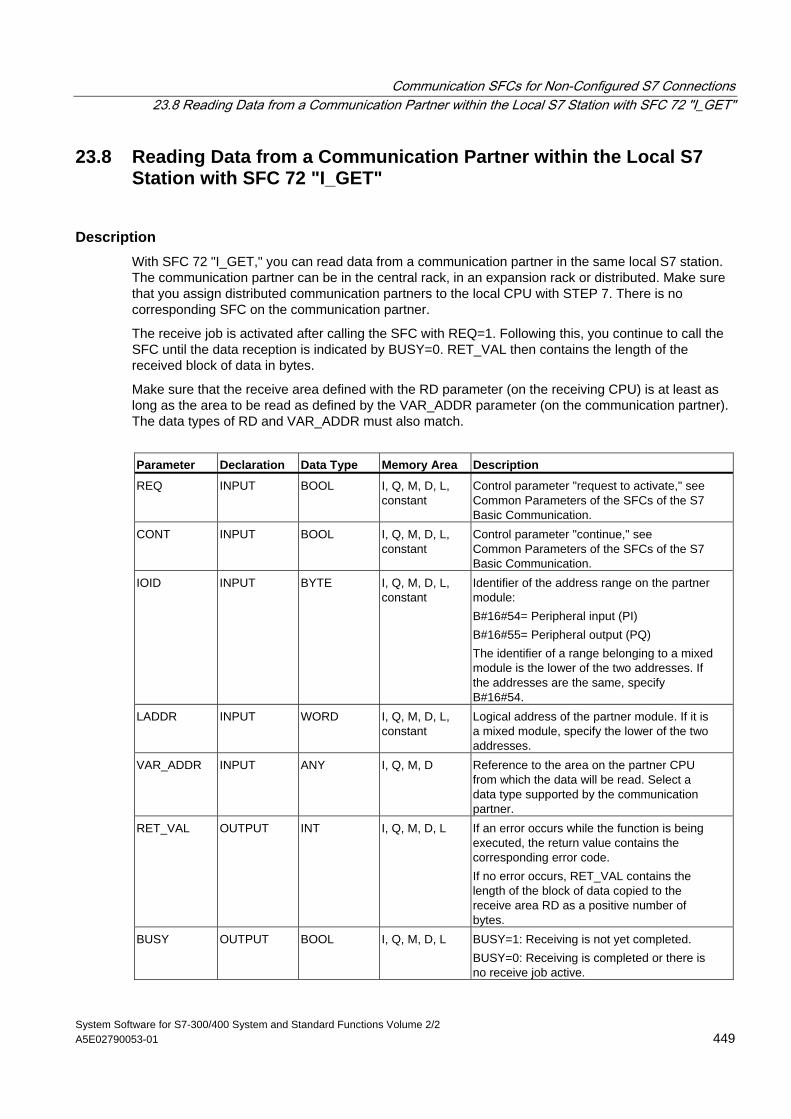
Communication SFCs for Non-Configured S7 Connections 23.8 Reading Data from a Communication Partner within the Local S7 Station with SFC 72 "I_GET"
System Software for S7-300/400 System and Standard Functions Volume 2/2 A5E02790053-01 449
23.8 Reading Data from a Communication Partner within the Local S7 Station with SFC 72 "I_GET"
Description With SFC 72 "I_GET," you can read data from a communication partner in the same local S7 station. The communication partner can be in the central rack, in an expansion rack or distributed. Make sure that you assign distributed communication partners to the local CPU with STEP 7. There is no corresponding SFC on the communication partner.
The receive job is activated after calling the SFC with REQ=1. Following this, you continue to call the SFC until the data reception is indicated by BUSY=0. RET_VAL then contains the length of the received block of data in bytes.
Make sure that the receive area defined with the RD parameter (on the receiving CPU) is at least as long as the area to be read as defined by the VAR_ADDR parameter (on the communication partner). The data types of RD and VAR_ADDR must also match.
Parameter Declaration Data Type Memory Area Description
REQ INPUT BOOL I, Q, M, D, L, constant
Control parameter "request to activate," see Common Parameters of the SFCs of the S7 Basic Communication.
CONT INPUT BOOL I, Q, M, D, L, constant
Control parameter "continue," see Common Parameters of the SFCs of the S7 Basic Communication.
IOID INPUT BYTE I, Q, M, D, L, constant
Identifier of the address range on the partner module: B#16#54= Peripheral input (PI) B#16#55= Peripheral output (PQ) The identifier of a range belonging to a mixed module is the lower of the two addresses. If the addresses are the same, specify B#16#54.
LADDR INPUT WORD I, Q, M, D, L, constant
Logical address of the partner module. If it is a mixed module, specify the lower of the two addresses.
VAR_ADDR INPUT ANY I, Q, M, D Reference to the area on the partner CPU from which the data will be read. Select a data type supported by the communication partner.
RET_VAL OUTPUT INT I, Q, M, D, L If an error occurs while the function is being executed, the return value contains the corresponding error code. If no error occurs, RET_VAL contains the length of the block of data copied to the receive area RD as a positive number of bytes.
BUSY OUTPUT BOOL I, Q, M, D, L BUSY=1: Receiving is not yet completed. BUSY=0: Receiving is completed or there is no receive job active.
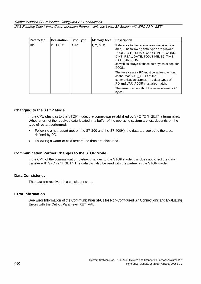
Communication SFCs for Non-Configured S7 Connections 23.8 Reading Data from a Communication Partner within the Local S7 Station with SFC 72 "I_GET"
System Software for S7-300/400 System and Standard Functions Volume 2/2 450 Reference Manual, 05/2010, A5E02790053-01
Parameter Declaration Data Type Memory Area Description
RD OUTPUT ANY I, Q, M, D Reference to the receive area (receive data area). The following data types are allowed: BOOL, BYTE, CHAR, WORD, INT, DWORD, DINT, REAL, DATE, TOD, TIME, S5_TIME, DATE_AND_TIME as well as arrays of these data types except for BOOL. The receive area RD must be at least as long as the read VAR_ADDR at the communication partner. The data types of RD and VAR_ADDR must also match. The maximum length of the receive area is 76 bytes.
Changing to the STOP Mode If the CPU changes to the STOP mode, the connection established by SFC 72 "I_GET" is terminated. Whether or not the received data located in a buffer of the operating system are lost depends on the type of restart performed:
• Following a hot restart (not on the S7-300 and the S7-400H), the data are copied to the area defined by RD.
• Following a warm or cold restart, the data are discarded.
Communication Partner Changes to the STOP Mode If the CPU of the communication partner changes to the STOP mode, this does not affect the data transfer with SFC 72 "I_GET." The data can also be read with the partner in the STOP mode.
Data Consistency The data are received in a consistent state.
Error Information See Error Information of the Communication SFCs for Non-Configured S7 Connections and Evaluating Errors with the Output Parameter RET_VAL
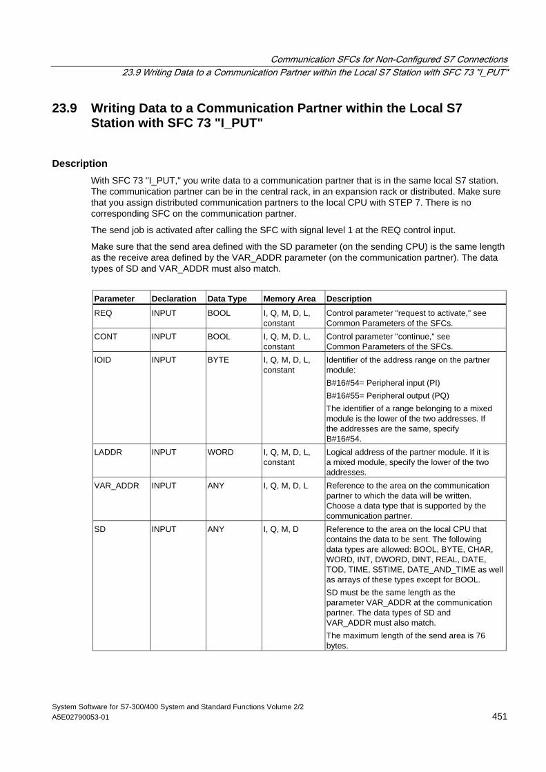
Communication SFCs for Non-Configured S7 Connections 23.9 Writing Data to a Communication Partner within the Local S7 Station with SFC 73 "I_PUT"
System Software for S7-300/400 System and Standard Functions Volume 2/2 A5E02790053-01 451
23.9 Writing Data to a Communication Partner within the Local S7 Station with SFC 73 "I_PUT"
Description With SFC 73 "I_PUT," you write data to a communication partner that is in the same local S7 station. The communication partner can be in the central rack, in an expansion rack or distributed. Make sure that you assign distributed communication partners to the local CPU with STEP 7. There is no corresponding SFC on the communication partner.
The send job is activated after calling the SFC with signal level 1 at the REQ control input.
Make sure that the send area defined with the SD parameter (on the sending CPU) is the same length as the receive area defined by the VAR_ADDR parameter (on the communication partner). The data types of SD and VAR_ADDR must also match.
Parameter Declaration Data Type Memory Area Description
REQ INPUT BOOL I, Q, M, D, L, constant
Control parameter "request to activate," see Common Parameters of the SFCs.
CONT INPUT BOOL I, Q, M, D, L, constant
Control parameter "continue," see Common Parameters of the SFCs.
IOID INPUT BYTE I, Q, M, D, L, constant
Identifier of the address range on the partner module: B#16#54= Peripheral input (PI) B#16#55= Peripheral output (PQ) The identifier of a range belonging to a mixed module is the lower of the two addresses. If the addresses are the same, specify B#16#54.
LADDR INPUT WORD I, Q, M, D, L, constant
Logical address of the partner module. If it is a mixed module, specify the lower of the two addresses.
VAR_ADDR INPUT ANY I, Q, M, D, L Reference to the area on the communication partner to which the data will be written. Choose a data type that is supported by the communication partner.
SD INPUT ANY I, Q, M, D Reference to the area on the local CPU that contains the data to be sent. The following data types are allowed: BOOL, BYTE, CHAR, WORD, INT, DWORD, DINT, REAL, DATE, TOD, TIME, S5TIME, DATE_AND_TIME as well as arrays of these types except for BOOL. SD must be the same length as the parameter VAR_ADDR at the communication partner. The data types of SD and VAR_ADDR must also match. The maximum length of the send area is 76 bytes.
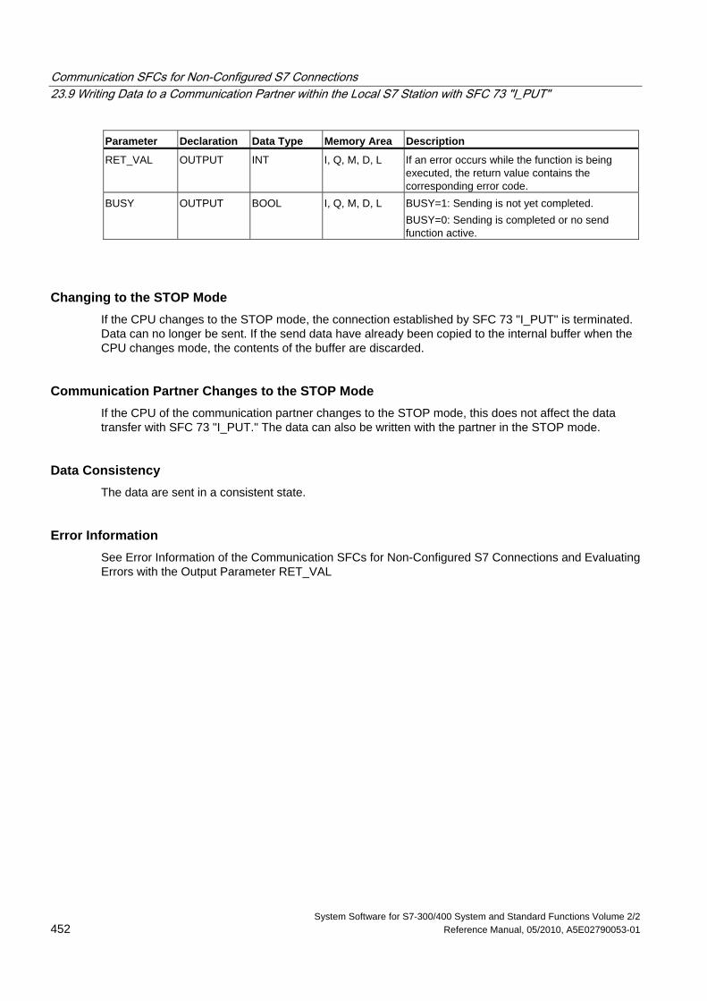
Communication SFCs for Non-Configured S7 Connections 23.9 Writing Data to a Communication Partner within the Local S7 Station with SFC 73 "I_PUT"
System Software for S7-300/400 System and Standard Functions Volume 2/2 452 Reference Manual, 05/2010, A5E02790053-01
Parameter Declaration Data Type Memory Area Description
RET_VAL OUTPUT INT I, Q, M, D, L If an error occurs while the function is being executed, the return value contains the corresponding error code.
BUSY OUTPUT BOOL I, Q, M, D, L BUSY=1: Sending is not yet completed. BUSY=0: Sending is completed or no send function active.
Changing to the STOP Mode If the CPU changes to the STOP mode, the connection established by SFC 73 "I_PUT" is terminated. Data can no longer be sent. If the send data have already been copied to the internal buffer when the CPU changes mode, the contents of the buffer are discarded.
Communication Partner Changes to the STOP Mode If the CPU of the communication partner changes to the STOP mode, this does not affect the data transfer with SFC 73 "I_PUT." The data can also be written with the partner in the STOP mode.
Data Consistency The data are sent in a consistent state.
Error Information See Error Information of the Communication SFCs for Non-Configured S7 Connections and Evaluating Errors with the Output Parameter RET_VAL
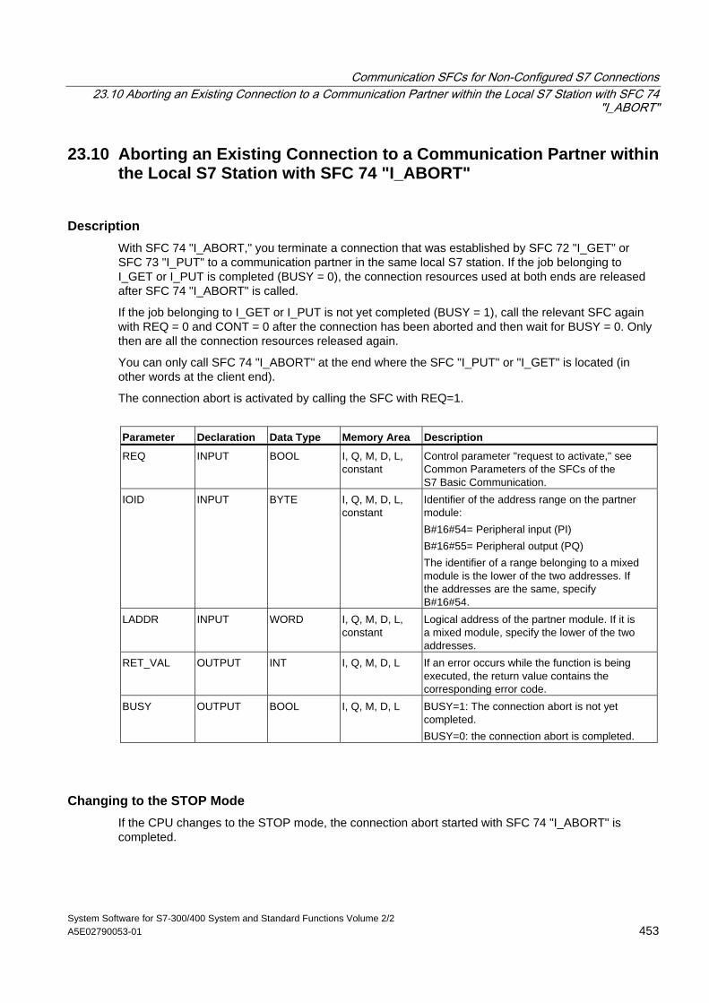
Communication SFCs for Non-Configured S7 Connections 23.10 Aborting an Existing Connection to a Communication Partner within the Local S7 Station with SFC 74
"I_ABORT"
System Software for S7-300/400 System and Standard Functions Volume 2/2 A5E02790053-01 453
23.10 Aborting an Existing Connection to a Communication Partner within the Local S7 Station with SFC 74 "I_ABORT"
Description With SFC 74 "I_ABORT," you terminate a connection that was established by SFC 72 "I_GET" or SFC 73 "I_PUT" to a communication partner in the same local S7 station. If the job belonging to I_GET or I_PUT is completed (BUSY = 0), the connection resources used at both ends are released after SFC 74 "I_ABORT" is called.
If the job belonging to I_GET or I_PUT is not yet completed (BUSY = 1), call the relevant SFC again with REQ = 0 and CONT = 0 after the connection has been aborted and then wait for BUSY = 0. Only then are all the connection resources released again.
You can only call SFC 74 "I_ABORT" at the end where the SFC "I_PUT" or "I_GET" is located (in other words at the client end).
The connection abort is activated by calling the SFC with REQ=1.
Parameter Declaration Data Type Memory Area Description
REQ INPUT BOOL I, Q, M, D, L, constant
Control parameter "request to activate," see Common Parameters of the SFCs of the S7 Basic Communication.
IOID INPUT BYTE I, Q, M, D, L, constant
Identifier of the address range on the partner module: B#16#54= Peripheral input (PI) B#16#55= Peripheral output (PQ) The identifier of a range belonging to a mixed module is the lower of the two addresses. If the addresses are the same, specify B#16#54.
LADDR INPUT WORD I, Q, M, D, L, constant
Logical address of the partner module. If it is a mixed module, specify the lower of the two addresses.
RET_VAL OUTPUT INT I, Q, M, D, L If an error occurs while the function is being executed, the return value contains the corresponding error code.
BUSY OUTPUT BOOL I, Q, M, D, L BUSY=1: The connection abort is not yet completed. BUSY=0: the connection abort is completed.
Changing to the STOP Mode If the CPU changes to the STOP mode, the connection abort started with SFC 74 "I_ABORT" is completed.
Communication SFCs for Non-Configured S7 Connections 23.10 Aborting an Existing Connection to a Communication Partner within the Local S7 Station with SFC 74 "I_ABORT"
System Software for S7-300/400 System and Standard Functions Volume 2/2 454 Reference Manual, 05/2010, A5E02790053-01
Communication Partner Changes to the STOP Mode If the CPU of the communication partner changes to the STOP mode, this does not affect the connection abort with SFC 74 "I_ABORT." The connection is terminated.
Error Information See Error Information of the Communication SFCs for Non-Configured S7 Connections and Evaluating Errors with the Output Parameter RET_VAL
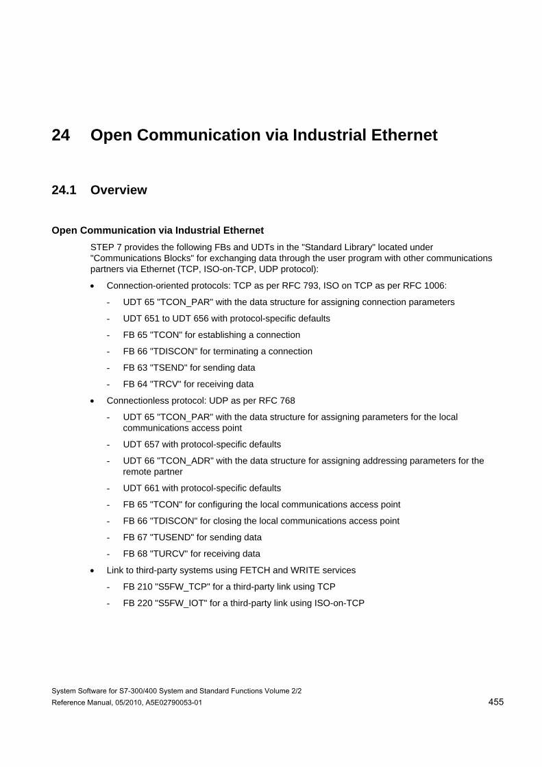
System Software for S7-300/400 System and Standard Functions Volume 2/2 Reference Manual, 05/2010, A5E02790053-01 455
24 Open Communication via Industrial Ethernet
24.1 Overview
Open Communication via Industrial Ethernet STEP 7 provides the following FBs and UDTs in the "Standard Library" located under "Communications Blocks" for exchanging data through the user program with other communications partners via Ethernet (TCP, ISO-on-TCP, UDP protocol):
• Connection-oriented protocols: TCP as per RFC 793, ISO on TCP as per RFC 1006:
- UDT 65 "TCON_PAR" with the data structure for assigning connection parameters
- UDT 651 to UDT 656 with protocol-specific defaults
- FB 65 "TCON" for establishing a connection
- FB 66 "TDISCON" for terminating a connection
- FB 63 "TSEND" for sending data
- FB 64 "TRCV" for receiving data
• Connectionless protocol: UDP as per RFC 768
- UDT 65 "TCON_PAR" with the data structure for assigning parameters for the local communications access point
- UDT 657 with protocol-specific defaults
- UDT 66 "TCON_ADR" with the data structure for assigning addressing parameters for the remote partner
- UDT 661 with protocol-specific defaults
- FB 65 "TCON" for configuring the local communications access point
- FB 66 "TDISCON" for closing the local communications access point
- FB 67 "TUSEND" for sending data
- FB 68 "TURCV" for receiving data
• Link to third-party systems using FETCH and WRITE services
- FB 210 "S5FW_TCP" for a third-party link using TCP
- FB 220 "S5FW_IOT" for a third-party link using ISO-on-TCP
Open Communication via Industrial Ethernet 24.2 Function of FBs for Open Communication via Industrial Ethernet
System Software for S7-300/400 System and Standard Functions Volume 2/2 456 Reference Manual, 05/2010, A5E02790053-01
24.2 Function of FBs for Open Communication via Industrial Ethernet
Connection-oriented and Connectionless Protocols The following protocol variants are distinguished in the data communication:
• Connection-oriented protocol variants: These establish a logical connection to the communication partner before data transmission is started. After the data transmission is complete, they then terminate the connection, if necessary. Connection-oriented protocols are used for data transmission when reliable, guaranteed delivery is of particular importance. In general, many logical connections can exist on one physical line. The following connection-oriented protocols are supported with FBs for open communication via Industrial Ethernet:
- TCP/IP as per RFC 793
- ISO on TCP as per RFC 1006
• Connectionless protocol variant: These work without a connection. There is thus no establishment and termination of a connection with a remote partner. Connectionless protocols transmit data unacknowledged, with no reliable, guaranteed delivery to the remote partner; in other words, data can be lost without this being indicated by the block. The following connection-oriented protocols are supported by FBs for open communication via Industrial Ethernet:
- UDP as per RFC 768
How the function blocks actually function depends on the protocol variant being used. This is discussed in detail in the following section.
Receive area This term will be used repeatedly in the following sections. This means the area in which the function block enters the received data.
The receive area in the specified by the following two variables:
• Pointer to the start of the area
• Length of the area
The length of the area is specified depending on the protocol variant being used by the LEN parameter (if LEN <> 0) or the length information of the DATA parameter (if LEN = 0).
The following data types are allowed in the ANY pointer: BOOL, BYTE, CHAR, WORD, INT, DWORD, DINT, REAL, DATE, TIME_OF_DAY, TIME, S5TIME, DATE_AND_TIME.
Open Communication via Industrial Ethernet 24.2 Function of FBs for Open Communication via Industrial Ethernet
System Software for S7-300/400 System and Standard Functions Volume 2/2 A5E02790053-01 457
TCP During data transmission, no information about the length or about the start and end of a message is transmitted. This is not a problem during sending because the sender knows how many data bytes it will be sending. However, the receiver has no means of detecting where one message ends in the data stream and the next one begins. It is therefore recommended that you set the receive area of FB64 "TRCV" to exactly the value of the LEN parameter of FB63 "TSEND" on the communication partner (number of bytes to be sent).
• Receiving data in ad-hoc mode: The receive area is identical to the area specified with the DATA parameter of FB64 "TRCV" Immediately after receiving a block of data, FB 64 "TRCV" transfers to the receive area and sets NDR to 1. The maximum length is 8192 bytes. If the length selected for the receive area is greater than the length of the sent data, FB 64 "TRCV" enters the received data completely in the receive area. It then sets NDR to TRUE and write the length of the received data to RCVD_LEN. If you have selected a receive area with a length smaller than the length of the sent data, FB64 copies as many bytes as possible to the receive area until it is full. It then sets NDR to TRUE and writes the length of the receive area to RCVD_LEN. With each further call, you receive a further block of the sent data.
• Receiving data with preset length: The receive area is defined by the DATA parameter (start address of the receive area) and LEN parameter (length of the receive area) of FB64. If data is received that does not completely fill the receive area, this data is not initially available to you. It only becomes available when further data has filled up the receive area completely. Please note that in this case data from two different send jobs are located in the same receive area. If you cannot recognize the end of the first message or the start of the second message, you will not be able to detect the first or second message. If you have selected a receive area with a length smaller than the length of the sent data, FB64 copies as many bytes as possible to the receive area until it is filled completely. When FB64 has completely filled the receive area, it sets NDR to TRUE and writes the value of LEN to RCVD_LEN. With each further call, you therefore receive a further block of the sent data.
Open Communication via Industrial Ethernet 24.2 Function of FBs for Open Communication via Industrial Ethernet
System Software for S7-300/400 System and Standard Functions Volume 2/2 458 Reference Manual, 05/2010, A5E02790053-01
ISO on-TCP During data transfer, information on the length and end of a message is also transferred.
If you have selected a receive area that is longer than the sent data, FB64 "TRCV" enters all the data in the receive area. It then sets NDR to TRUE and writes the length of the sent data to RCVD_LEN.
If you have selected a receive area shorter than the length of the sent data, FB64 does not copy any data to the receive area and returns the following error information: ERROR=1, STATUS=W#16#8088.
UDP There is no connection establishment as in the TCP and ISO-on-TCP protocols. You must therefore specify a reference to the address parameters of the recipient (IP address and port no.) when the send block FB 67 "TUSEND" is called. In the same way, on completion of the receive block FB 68 "TURCV", you receive a reference to the address parameters of the sender (IP address and port no.).
To be able to use FBs 67 "TUSEND" and 68 "TURCV", you will first need to call FB 65 "TCON" both at the sender and receiver end to set up the local communication access point.
Each time you call FB 67 "TUSEND", you can re-reference the remote partner by specifying its IP address and its port no.
During data transfer, information on the length and end of a message is also transferred.
If you have selected a receive area that is longer than the sent data, FB64 "TURCV" enters all the data in the receive area. It then sets NDR to TRUE and writes the length of the sent data to RCVD_LEN.
If you have selected a receive area shorter than the length of the sent data, FB64 does not copy any data to the receive area and returns the following error information: ERROR=1, STATUS=W#16#8088.
Open Communication via Industrial Ethernet 24.2 Function of FBs for Open Communication via Industrial Ethernet
System Software for S7-300/400 System and Standard Functions Volume 2/2 A5E02790053-01 459
Port Numbers for TCP and UDP A connection is addressed as follows:
• With TCP:
- Active connection: via the remote IP address, the remote port and via the local port (you either set the port number of the local port explicitly or it is assigned by the operating system).
- Passive connection: via the local port. If you want to use the local port more than once, you will also need to specify either the IP address or the remote IP address and the remote port.
• With UDP: via the remote IP address, the remote port and the local port (you set the port number of the local port explicitly).
The ranges listed below apply to the local port. These ranges apply to the remote port only if the remote partner is an S7 CPU. Otherwise there are no restrictions for the remote port.
• For CPUs 31x-2 PN/DP up to and including firmware version V2.6 and CPUs 41x-3 PN/DP up to and including firmware version V5.1:
- Permitted port numbers in the parameter assignment (UDT 65): 2000 to 5000
- If the parameter assignment does not include an explicitly set port number, the operating system assigns a port from the dynamic band of numbers between 49152 and 65534.
• For CPUs 31x-2 PN/DP as of firmware version V2.7 and CPUs 41x-3 PN/DP as of firmware version V5.2:
- Permitted port numbers in the parameter assignment (UDT 65): 1 to 49151 It is advisable to restrict the port numbers to 2000 to 5000 since Siemens reserve supports from the number ranges 1 to 1999 and 5001 to 49151 for the system.
- If the parameter assignment does not include an explicitly set port number, the operating system assigns a port from the dynamic band of numbers between 49152 and 65534.
• For CPUs 31x-2 PN/DP as of firmware version V3.2 and CPUs 41x-3 PN/DP as of firmware version V6.0:
- Multiple use of a port is possible.
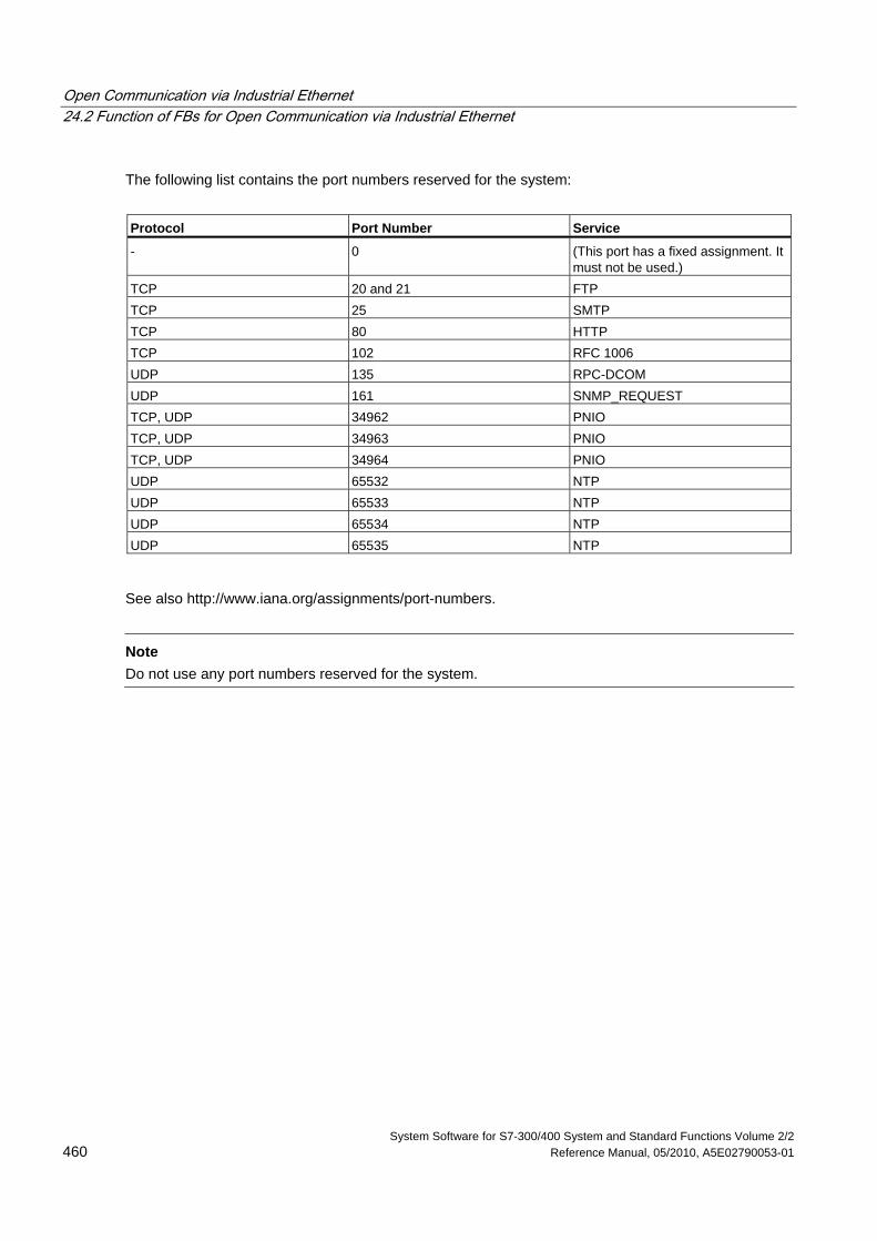
Open Communication via Industrial Ethernet 24.2 Function of FBs for Open Communication via Industrial Ethernet
System Software for S7-300/400 System and Standard Functions Volume 2/2 460 Reference Manual, 05/2010, A5E02790053-01
The following list contains the port numbers reserved for the system:
Protocol Port Number Service
- 0 (This port has a fixed assignment. It must not be used.)
TCP 20 and 21 FTP TCP 25 SMTP TCP 80 HTTP TCP 102 RFC 1006 UDP 135 RPC-DCOM UDP 161 SNMP_REQUEST TCP, UDP 34962 PNIO TCP, UDP 34963 PNIO TCP, UDP 34964 PNIO UDP 65532 NTP UDP 65533 NTP UDP 65534 NTP UDP 65535 NTP
See also http://www.iana.org/assignments/port-numbers.
Note
Do not use any port numbers reserved for the system.
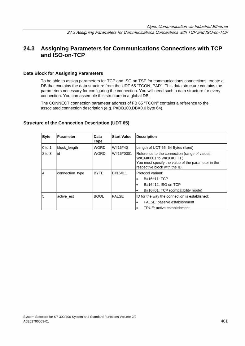
Open Communication via Industrial Ethernet 24.3 Assigning Parameters for Communications Connections with TCP and ISO-on-TCP
System Software for S7-300/400 System and Standard Functions Volume 2/2 A5E02790053-01 461
24.3 Assigning Parameters for Communications Connections with TCP and ISO-on-TCP
Data Block for Assigning Parameters To be able to assign parameters for TCP and ISO on TSP for communications connections, create a DB that contains the data structure from the UDT 65 "TCON_PAR". This data structure contains the parameters necessary for configuring the connection. You will need such a data structure for every connection. You can assemble this structure in a global DB.
The CONNECT connection parameter address of FB 65 "TCON" contains a reference to the associated connection description (e.g. P#DB100.DBX0.0 byte 64).
Structure of the Connection Description (UDT 65) Byte Parameter Data
Type Start Value Description
0 to 1 block_length WORD W#16#40 Length of UDT 65: 64 Bytes (fixed) 2 to 3 id WORD W#16#0001 Reference to the connection (range of values:
W#16#0001 to W#16#0FFF) You must specify the value of the parameter in the respective block with the ID.
4 connection_type BYTE B#16#11 Protocol variant: • B#16#11: TCP • B#16#12: ISO on TCP • B#16#01: TCP (compatibility mode)
5 active_est BOOL FALSE ID for the way the connection is established: • FALSE: passive establishment • TRUE: active establishment
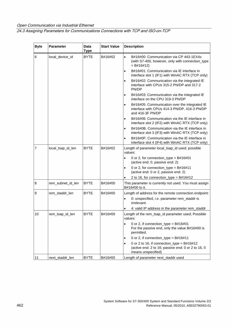
Open Communication via Industrial Ethernet 24.3 Assigning Parameters for Communications Connections with TCP and ISO-on-TCP
System Software for S7-300/400 System and Standard Functions Volume 2/2 462 Reference Manual, 05/2010, A5E02790053-01
Byte Parameter Data Type
Start Value Description
6 local_device_id BYTE B#16#02 • B#16#00: Communication via CP 443-1EX4x (with S7-400, however, only with connection_type = B#16#12)
• B#16#01: Communication via IE interface in interface slot 1 (IF1) with WinAC RTX (TCP only)
• B#16#02: Communication via the integrated IE interface with CPUs 315-2 PN/DP and 317-2 PN/DP
• B#16#03: Communication via the integrated IE interface on the CPU 319-3 PN/DP
• B#16#05: Communication over the integrated IE interface with CPUs 414-3 PN/DP, 416-3 PN/DP and 416-3F PN/DP
• B#16#06: Communication via the IE interface in interface slot 2 (IF2) with WinAC RTX (TCP only)
• B#16#0B. Communication via the IE interface in interface slot 3 (IF3) with WinAC RTX (TCP only)
• B#16#0F: Communication via the IE interface in interface slot 4 (IF4) with WinAC RTX (TCP only)
7 local_tsap_id_len BYTE B#16#02 Length of parameter local_tsap_id used; possible values: • 0 or 2, for connection_type = B#16#01
(active end: 0, passive end: 2) • 0 or 2, for connection_type = B#16#11
(active end: 0 or 2, passive end: 2) • 2 to 16, for connection_type = B#16#12
8 rem_subnet_id_len BYTE B#16#00 This parameter is currently not used. You must assign B#16#00 to it.
9 rem_staddr_len BYTE B#16#00 Length of address for the remote connection endpoint:• 0: unspecified, i.e. parameter rem_staddr is
irrelevant. • 4: valid IP address in the parameter rem_staddr
10 rem_tsap_id_len BYTE B#16#00 Length of the rem_tsap_id parameter used; Possible values: • 0 or 2, if connection_type = B#16#01
For the passive end, only the value B#16#00 is permitted.
• 0 or 2, if connection_type = B#16#11 • 0 or 2 to 16, if connection_type = B#16#12
(active end: 2 to 16; passive end: 0 or 2 to 16, 0 means unspecified)
11 next_staddr_len BYTE B#16#00 Length of parameter next_staddr used
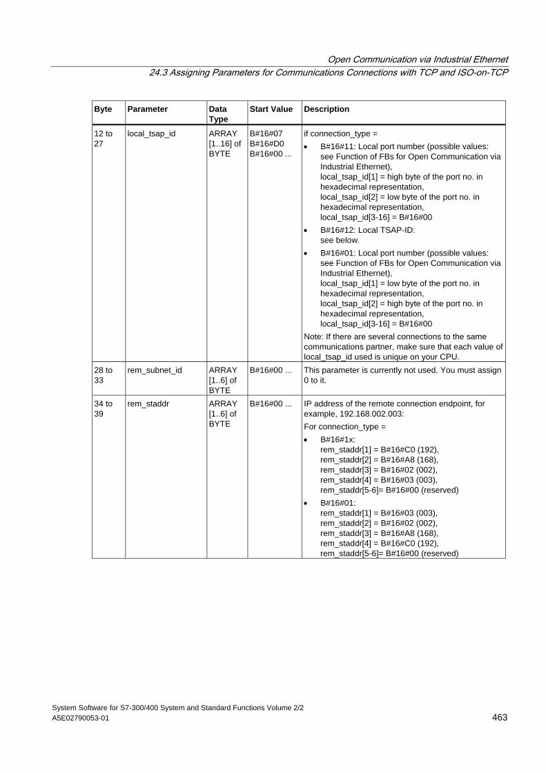
Open Communication via Industrial Ethernet 24.3 Assigning Parameters for Communications Connections with TCP and ISO-on-TCP
System Software for S7-300/400 System and Standard Functions Volume 2/2 A5E02790053-01 463
Byte Parameter Data Type
Start Value Description
12 to 27
local_tsap_id ARRAY [1..16] of BYTE
B#16#07 B#16#D0 B#16#00 ...
if connection_type = • B#16#11: Local port number (possible values:
see Function of FBs for Open Communication via Industrial Ethernet), local_tsap_id[1] = high byte of the port no. in hexadecimal representation, local_tsap_id[2] = low byte of the port no. in hexadecimal representation, local_tsap_id[3-16] = B#16#00
• B#16#12: Local TSAP-ID: see below.
• B#16#01: Local port number (possible values: see Function of FBs for Open Communication via Industrial Ethernet), local_tsap_id[1] = low byte of the port no. in hexadecimal representation, local_tsap_id[2] = high byte of the port no. in hexadecimal representation, local_tsap_id[3-16] = B#16#00
Note: If there are several connections to the same communications partner, make sure that each value of local_tsap_id used is unique on your CPU.
28 to 33
rem_subnet_id ARRAY [1..6] of BYTE
B#16#00 ... This parameter is currently not used. You must assign 0 to it.
34 to 39
rem_staddr ARRAY [1..6] of BYTE
B#16#00 ... IP address of the remote connection endpoint, for example, 192.168.002.003: For connection_type = • B#16#1x:
rem_staddr[1] = B#16#C0 (192), rem_staddr[2] = B#16#A8 (168), rem_staddr[3] = B#16#02 (002), rem_staddr[4] = B#16#03 (003), rem_staddr[5-6]= B#16#00 (reserved)
• B#16#01: rem_staddr[1] = B#16#03 (003), rem_staddr[2] = B#16#02 (002), rem_staddr[3] = B#16#A8 (168), rem_staddr[4] = B#16#C0 (192), rem_staddr[5-6]= B#16#00 (reserved)
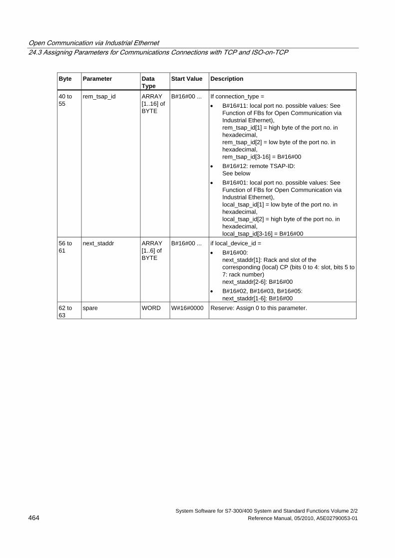
Open Communication via Industrial Ethernet 24.3 Assigning Parameters for Communications Connections with TCP and ISO-on-TCP
System Software for S7-300/400 System and Standard Functions Volume 2/2 464 Reference Manual, 05/2010, A5E02790053-01
Byte Parameter Data Type
Start Value Description
40 to 55
rem_tsap_id ARRAY [1..16] of BYTE
B#16#00 ... If connection_type = • B#16#11: local port no. possible values: See
Function of FBs for Open Communication via Industrial Ethernet), rem_tsap_id[1] = high byte of the port no. in hexadecimal, rem_tsap_id[2] = low byte of the port no. in hexadecimal, rem_tsap_id[3-16] = B#16#00
• B#16#12: remote TSAP-ID: See below
• B#16#01: local port no. possible values: See Function of FBs for Open Communication via Industrial Ethernet), local_tsap_id[1] = low byte of the port no. in hexadecimal, local_tsap_id[2] = high byte of the port no. in hexadecimal, local_tsap_id[3-16] = B#16#00
56 to 61
next_staddr ARRAY [1..6] of BYTE
B#16#00 ... if local_device_id = • B#16#00:
next_staddr[1]: Rack and slot of the corresponding (local) CP (bits 0 to 4: slot, bits 5 to7: rack number) next_staddr[2-6]: B#16#00
• B#16#02, B#16#03, B#16#05: next_staddr[1-6]: B#16#00
62 to 63
spare WORD W#16#0000 Reserve: Assign 0 to this parameter.
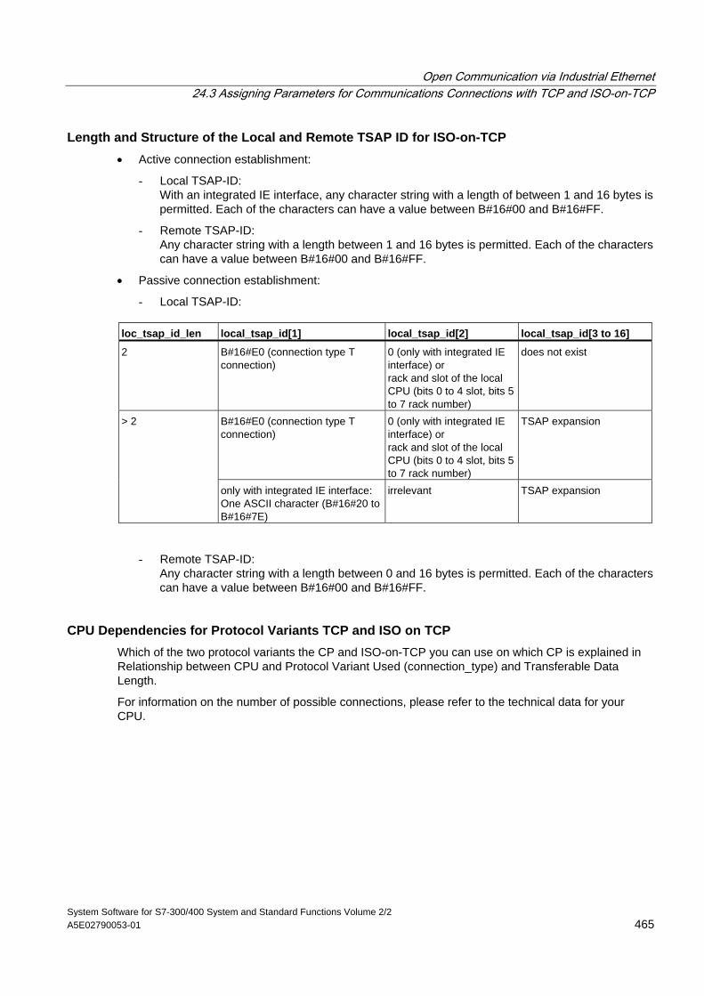
Open Communication via Industrial Ethernet 24.3 Assigning Parameters for Communications Connections with TCP and ISO-on-TCP
System Software for S7-300/400 System and Standard Functions Volume 2/2 A5E02790053-01 465
Length and Structure of the Local and Remote TSAP ID for ISO-on-TCP • Active connection establishment:
- Local TSAP-ID: With an integrated IE interface, any character string with a length of between 1 and 16 bytes is permitted. Each of the characters can have a value between B#16#00 and B#16#FF.
- Remote TSAP-ID: Any character string with a length between 1 and 16 bytes is permitted. Each of the characters can have a value between B#16#00 and B#16#FF.
• Passive connection establishment:
- Local TSAP-ID:
loc_tsap_id_len local_tsap_id[1] local_tsap_id[2] local_tsap_id[3 to 16]
2 B#16#E0 (connection type T connection)
0 (only with integrated IE interface) or rack and slot of the local CPU (bits 0 to 4 slot, bits 5 to 7 rack number)
does not exist
B#16#E0 (connection type T connection)
0 (only with integrated IE interface) or rack and slot of the local CPU (bits 0 to 4 slot, bits 5 to 7 rack number)
TSAP expansion > 2
only with integrated IE interface: One ASCII character (B#16#20 to B#16#7E)
irrelevant TSAP expansion
- Remote TSAP-ID: Any character string with a length between 0 and 16 bytes is permitted. Each of the characters can have a value between B#16#00 and B#16#FF.
CPU Dependencies for Protocol Variants TCP and ISO on TCP Which of the two protocol variants the CP and ISO-on-TCP you can use on which CP is explained in Relationship between CPU and Protocol Variant Used (connection_type) and Transferable Data Length.
For information on the number of possible connections, please refer to the technical data for your CPU.
Open Communication via Industrial Ethernet 24.3 Assigning Parameters for Communications Connections with TCP and ISO-on-TCP
System Software for S7-300/400 System and Standard Functions Volume 2/2 466 Reference Manual, 05/2010, A5E02790053-01
Establishing a Connection The establishment of an active connection must be initiated by a communications partner A. The establishment of a passive connection must be initiated by a communications partner B. If both communications partners have initiated the establishment of a connection, the operating system can completely establish a connection.
In the parameters for the connection, you specify which communications partner activates the establishment of a connection and which establishes a connection passively upon request of the communications partner
In UDP, both partners must initiate passive connection establishment.
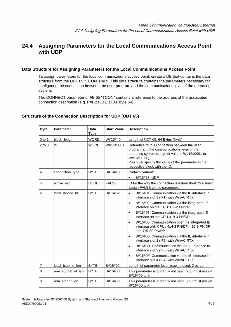
Open Communication via Industrial Ethernet 24.4 Assigning Parameters for the Local Communications Access Point with UDP
System Software for S7-300/400 System and Standard Functions Volume 2/2 A5E02790053-01 467
24.4 Assigning Parameters for the Local Communications Access Point with UDP
Data Structure for Assigning Parameters for the Local Communications Access Point To assign parameters for the local communications access point, create a DB that contains the data structure from the UDT 65 "TCON_PAR". This data structure contains the parameters necessary for configuring the connection between the user program and the communications level of the operating system.
The CONNECT parameter of FB 65 "TCON" contains a reference to the address of the associated connection description (e.g. P#DB100.DBX0.0 byte 64).
Structure of the Connection Description for UDP (UDT 65) Byte Parameter Data
Type Start Value Description
0 to 1 block_length WORD W#16#40 Length of UDT 65: 64 Bytes (fixed) 2 to 3 id WORD W#16#0001 Reference to this connection between the user
program and the communications level of the operating system (range of values: W#16#0001 to W#16#0FFF) You must specify the value of the parameter in the respective block with the ID.
4 connection_type BYTE B#16#13 Protocol variant: • B#16#13: UDP
5 active_est BOOL FALSE ID for the way the connection is established: You must assign FALSE to this parameter.
6 local_device_id BYTE B#16#02 • B#16#01: Communication via the IE interface in interface slot 1 (IF1) with WinAC RTX
• B#16#02: Communication via the integrated IE interface on the CPU 317-2 PN/DP
• B#16#03: Communication via the integrated IE interface on the CPU 319-3 PN/DP
• B#16#05: Communication over the integrated IE interface with CPUs 414-3 PN/DP, 416-3 PN/DP and 416-3F PN/DP
• B#16#06: Communication via the IE interface in interface slot 2 (IF2) with WinAC RTX
• B#16#0B. Communication via the IE interface in interface slot 3 (IF3) with WinAC RTX
• B#16#0F: Communication via the IE interface in interface slot 4 (IF4) with WinAC RTX
7 local_tsap_id_len BYTE B#16#02 Length of parameter local_tsap_id used; 2 bytes 8 rem_subnet_id_len BYTE B#16#00 This parameter is currently not used. You must assign
B#16#00 to it. 9 rem_staddr_len BYTE B#16#00 This parameter is currently not used. You must assign
B#16#00 to it.
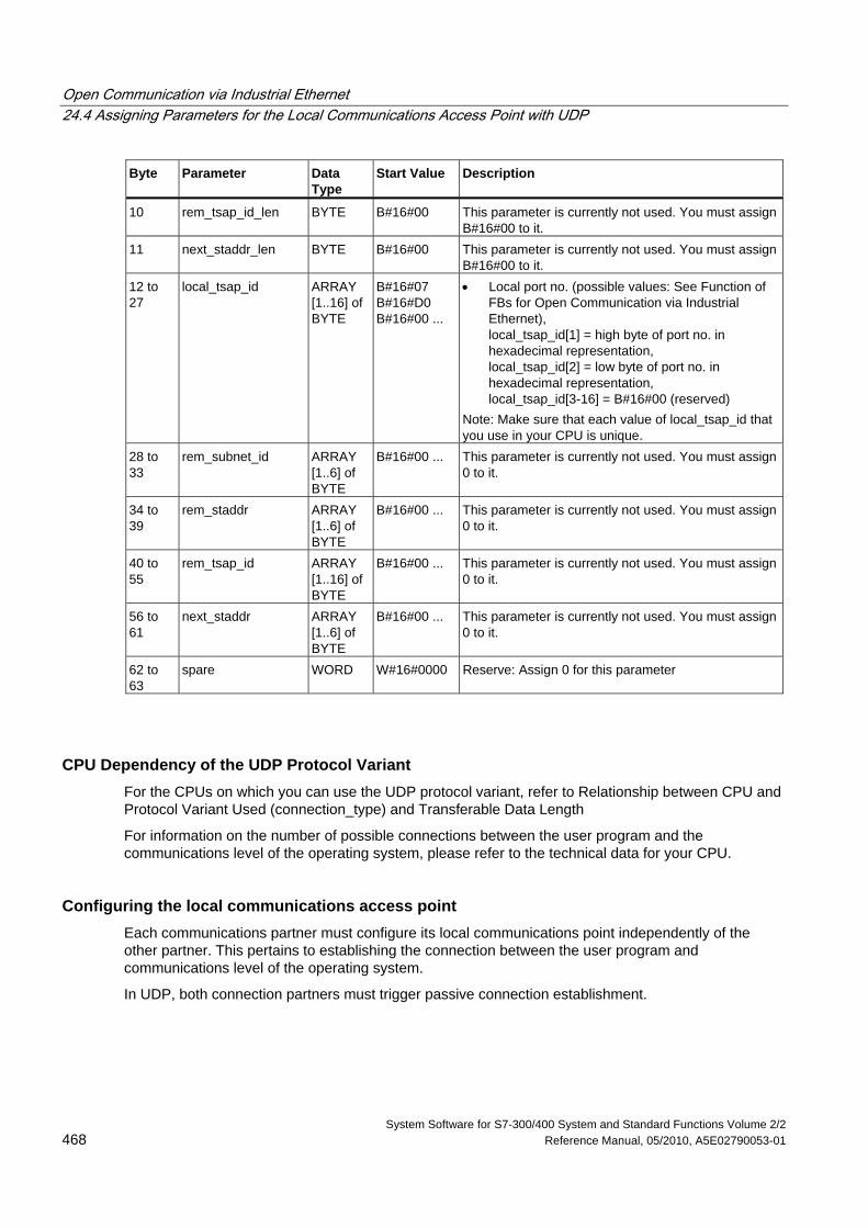
Open Communication via Industrial Ethernet 24.4 Assigning Parameters for the Local Communications Access Point with UDP
System Software for S7-300/400 System and Standard Functions Volume 2/2 468 Reference Manual, 05/2010, A5E02790053-01
Byte Parameter Data Type
Start Value Description
10 rem_tsap_id_len BYTE B#16#00 This parameter is currently not used. You must assign B#16#00 to it.
11 next_staddr_len BYTE B#16#00 This parameter is currently not used. You must assign B#16#00 to it.
12 to 27
local_tsap_id ARRAY [1..16] of BYTE
B#16#07 B#16#D0 B#16#00 ...
• Local port no. (possible values: See Function of FBs for Open Communication via Industrial Ethernet), local_tsap_id[1] = high byte of port no. in hexadecimal representation, local_tsap_id[2] = low byte of port no. in hexadecimal representation, local_tsap_id[3-16] = B#16#00 (reserved)
Note: Make sure that each value of local_tsap_id that you use in your CPU is unique.
28 to 33
rem_subnet_id ARRAY [1..6] of BYTE
B#16#00 ... This parameter is currently not used. You must assign 0 to it.
34 to 39
rem_staddr ARRAY [1..6] of BYTE
B#16#00 ... This parameter is currently not used. You must assign 0 to it.
40 to 55
rem_tsap_id ARRAY [1..16] of BYTE
B#16#00 ... This parameter is currently not used. You must assign 0 to it.
56 to 61
next_staddr ARRAY [1..6] of BYTE
B#16#00 ... This parameter is currently not used. You must assign 0 to it.
62 to 63
spare WORD W#16#0000 Reserve: Assign 0 for this parameter
CPU Dependency of the UDP Protocol Variant For the CPUs on which you can use the UDP protocol variant, refer to Relationship between CPU and Protocol Variant Used (connection_type) and Transferable Data Length
For information on the number of possible connections between the user program and the communications level of the operating system, please refer to the technical data for your CPU.
Configuring the local communications access point Each communications partner must configure its local communications point independently of the other partner. This pertains to establishing the connection between the user program and communications level of the operating system.
In UDP, both connection partners must trigger passive connection establishment.
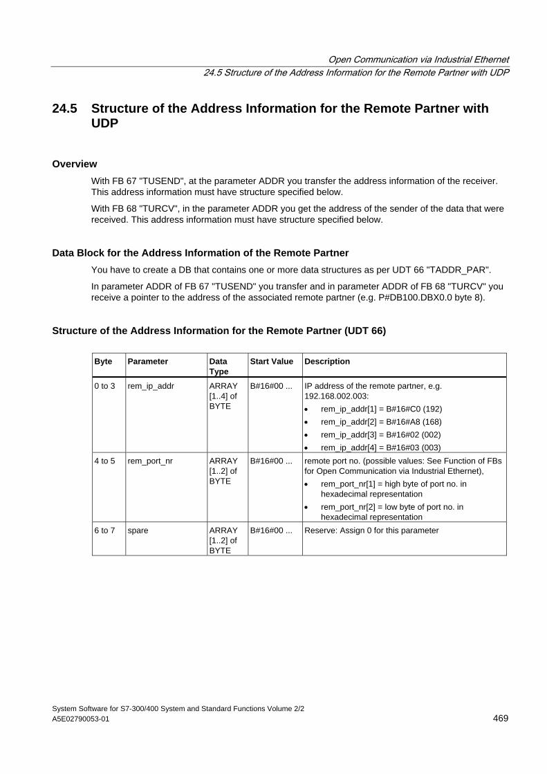
Open Communication via Industrial Ethernet 24.5 Structure of the Address Information for the Remote Partner with UDP
System Software for S7-300/400 System and Standard Functions Volume 2/2 A5E02790053-01 469
24.5 Structure of the Address Information for the Remote Partner with UDP
Overview With FB 67 "TUSEND", at the parameter ADDR you transfer the address information of the receiver. This address information must have structure specified below.
With FB 68 "TURCV", in the parameter ADDR you get the address of the sender of the data that were received. This address information must have structure specified below.
Data Block for the Address Information of the Remote Partner You have to create a DB that contains one or more data structures as per UDT 66 "TADDR_PAR".
In parameter ADDR of FB 67 "TUSEND" you transfer and in parameter ADDR of FB 68 "TURCV" you receive a pointer to the address of the associated remote partner (e.g. P#DB100.DBX0.0 byte 8).
Structure of the Address Information for the Remote Partner (UDT 66) Byte Parameter Data
Type Start Value Description
0 to 3 rem_ip_addr ARRAY [1..4] of BYTE
B#16#00 ... IP address of the remote partner, e.g. 192.168.002.003: • rem_ip_addr[1] = B#16#C0 (192) • rem_ip_addr[2] = B#16#A8 (168) • rem_ip_addr[3] = B#16#02 (002) • rem_ip_addr[4] = B#16#03 (003)
4 to 5 rem_port_nr ARRAY [1..2] of BYTE
B#16#00 ... remote port no. (possible values: See Function of FBs for Open Communication via Industrial Ethernet), • rem_port_nr[1] = high byte of port no. in
hexadecimal representation • rem_port_nr[2] = low byte of port no. in
hexadecimal representation 6 to 7 spare ARRAY
[1..2] of BYTE
B#16#00 ... Reserve: Assign 0 for this parameter
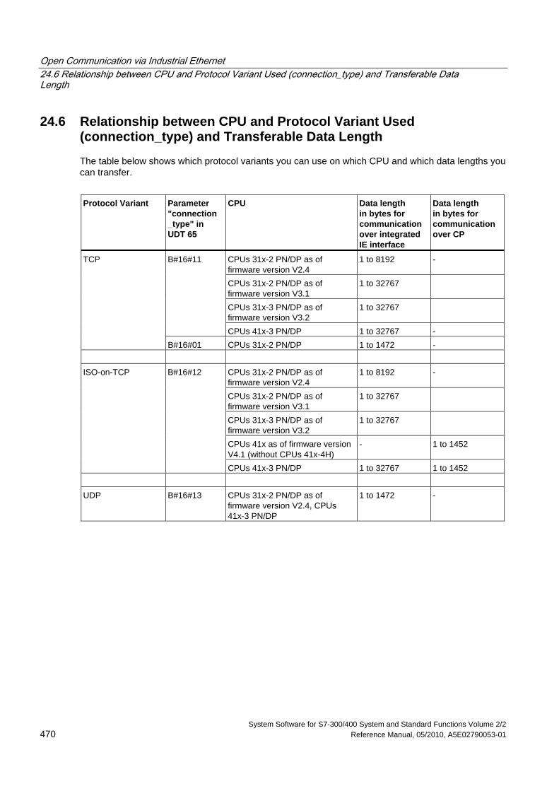
Open Communication via Industrial Ethernet 24.6 Relationship between CPU and Protocol Variant Used (connection_type) and Transferable Data Length
System Software for S7-300/400 System and Standard Functions Volume 2/2 470 Reference Manual, 05/2010, A5E02790053-01
24.6 Relationship between CPU and Protocol Variant Used (connection_type) and Transferable Data Length
The table below shows which protocol variants you can use on which CPU and which data lengths you can transfer.
Protocol Variant Parameter
"connection _type" in UDT 65
CPU Data length in bytes for communication over integrated IE interface
Data length in bytes for communication over CP
CPUs 31x-2 PN/DP as of firmware version V2.4
1 to 8192 -
CPUs 31x-2 PN/DP as of firmware version V3.1
1 to 32767
CPUs 31x-3 PN/DP as of firmware version V3.2
1 to 32767
B#16#11
CPUs 41x-3 PN/DP 1 to 32767 -
TCP
B#16#01 CPUs 31x-2 PN/DP 1 to 1472 -
CPUs 31x-2 PN/DP as of firmware version V2.4
1 to 8192 -
CPUs 31x-2 PN/DP as of firmware version V3.1
1 to 32767
CPUs 31x-3 PN/DP as of firmware version V3.2
1 to 32767
CPUs 41x as of firmware version V4.1 (without CPUs 41x-4H)
- 1 to 1452
ISO-on-TCP B#16#12
CPUs 41x-3 PN/DP 1 to 32767 1 to 1452 UDP B#16#13 CPUs 31x-2 PN/DP as of
firmware version V2.4, CPUs 41x-3 PN/DP
1 to 1472 -
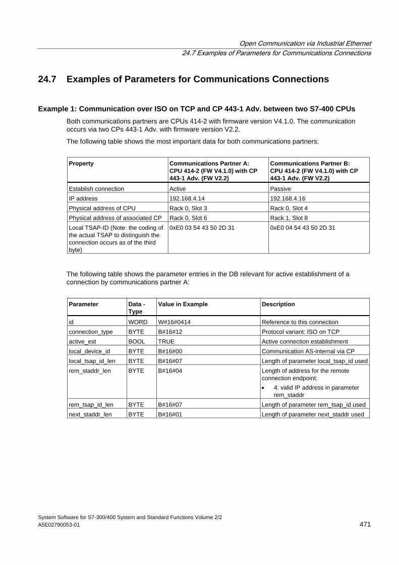
Open Communication via Industrial Ethernet 24.7 Examples of Parameters for Communications Connections
System Software for S7-300/400 System and Standard Functions Volume 2/2 A5E02790053-01 471
24.7 Examples of Parameters for Communications Connections
Example 1: Communication over ISO on TCP and CP 443-1 Adv. between two S7-400 CPUs Both communications partners are CPUs 414-2 with firmware version V4.1.0. The communication occurs via two CPs 443-1 Adv. with firmware version V2.2.
The following table shows the most important data for both communications partners:
Property Communications Partner A:
CPU 414-2 (FW V4.1.0) with CP 443-1 Adv. (FW V2.2)
Communications Partner B: CPU 414-2 (FW V4.1.0) with CP 443-1 Adv. (FW V2.2)
Establish connection Active Passive IP address 192.168.4.14 192.168.4.16 Physical address of CPU Rack 0, Slot 3 Rack 0, Slot 4 Physical address of associated CP Rack 0, Slot 6 Rack 1, Slot 8 Local TSAP-ID (Note: the coding of the actual TSAP to distinguish the connection occurs as of the third byte)
0xE0 03 54 43 50 2D 31 0xE0 04 54 43 50 2D 31
The following table shows the parameter entries in the DB relevant for active establishment of a connection by communications partner A:
Parameter Data -
Type Value in Example Description
id WORD W#16#0414 Reference to this connection connection_type BYTE B#16#12 Protocol variant: ISO on TCP active_est BOOL TRUE Active connection establishment local_device_id BYTE B#16#00 Communication AS-internal via CP local_tsap_id_len BYTE B#16#07 Length of parameter local_tsap_id usedrem_staddr_len BYTE B#16#04 Length of address for the remote
connection endpoint: • 4: valid IP address in parameter
rem_staddr rem_tsap_id_len BYTE B#16#07 Length of parameter rem_tsap_id used next_staddr_len BYTE B#16#01 Length of parameter next_staddr used
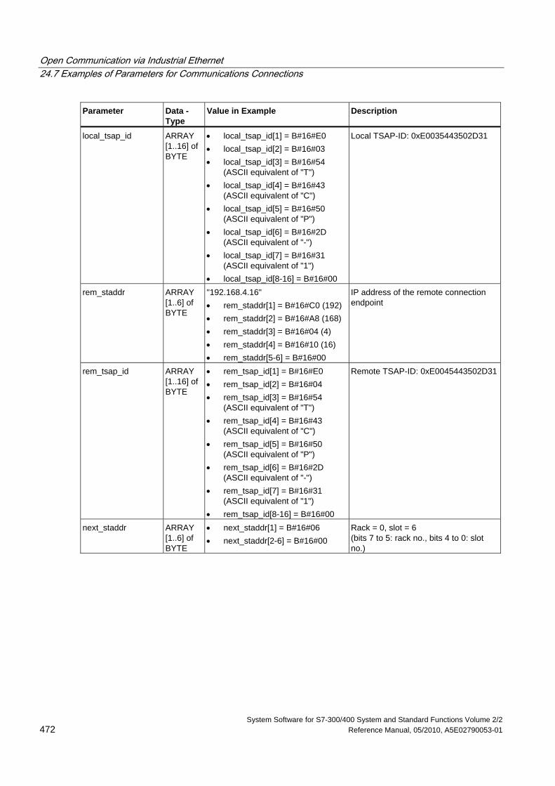
Open Communication via Industrial Ethernet 24.7 Examples of Parameters for Communications Connections
System Software for S7-300/400 System and Standard Functions Volume 2/2 472 Reference Manual, 05/2010, A5E02790053-01
Parameter Data - Type
Value in Example Description
local_tsap_id ARRAY [1..16] of BYTE
• local_tsap_id[1] = B#16#E0 • local_tsap_id[2] = B#16#03 • local_tsap_id[3] = B#16#54
(ASCII equivalent of "T") • local_tsap_id[4] = B#16#43
(ASCII equivalent of "C") • local_tsap_id[5] = B#16#50
(ASCII equivalent of "P") • local_tsap_id[6] = B#16#2D
(ASCII equivalent of "-") • local_tsap_id[7] = B#16#31
(ASCII equivalent of "1") • local_tsap_id[8-16] = B#16#00
Local TSAP-ID: 0xE0035443502D31
rem_staddr ARRAY [1..6] of BYTE
"192.168.4.16" • rem_staddr[1] = B#16#C0 (192) • rem_staddr[2] = B#16#A8 (168) • rem_staddr[3] = B#16#04 (4) • rem_staddr[4] = B#16#10 (16) • rem_staddr[5-6] = B#16#00
IP address of the remote connection endpoint
rem_tsap_id ARRAY [1..16] of BYTE
• rem_tsap_id[1] = B#16#E0 • rem_tsap_id[2] = B#16#04 • rem_tsap_id[3] = B#16#54
(ASCII equivalent of "T") • rem_tsap_id[4] = B#16#43
(ASCII equivalent of "C") • rem_tsap_id[5] = B#16#50
(ASCII equivalent of "P") • rem_tsap_id[6] = B#16#2D
(ASCII equivalent of "-") • rem_tsap_id[7] = B#16#31
(ASCII equivalent of "1") • rem_tsap_id[8-16] = B#16#00
Remote TSAP-ID: 0xE0045443502D31
next_staddr ARRAY [1..6] of BYTE
• next_staddr[1] = B#16#06 • next_staddr[2-6] = B#16#00
Rack = 0, slot = 6 (bits 7 to 5: rack no., bits 4 to 0: slot no.)
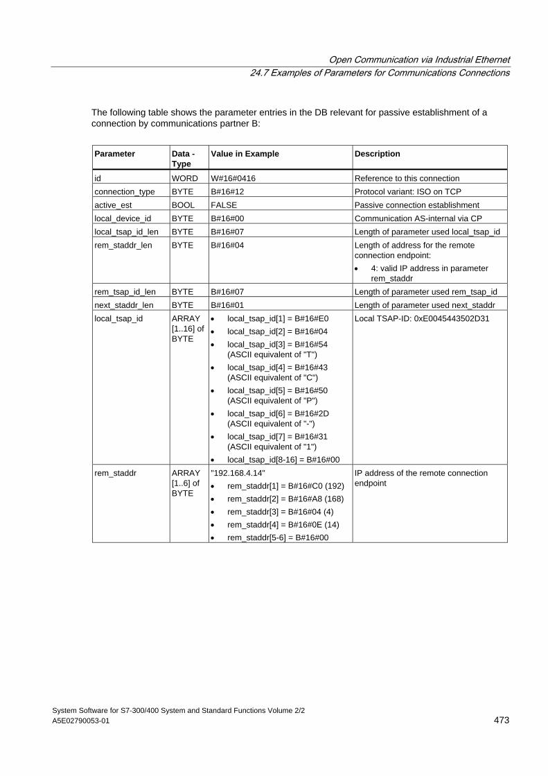
Open Communication via Industrial Ethernet 24.7 Examples of Parameters for Communications Connections
System Software for S7-300/400 System and Standard Functions Volume 2/2 A5E02790053-01 473
The following table shows the parameter entries in the DB relevant for passive establishment of a connection by communications partner B:
Parameter Data -
Type Value in Example Description
id WORD W#16#0416 Reference to this connection connection_type BYTE B#16#12 Protocol variant: ISO on TCP active_est BOOL FALSE Passive connection establishment local_device_id BYTE B#16#00 Communication AS-internal via CP local_tsap_id_len BYTE B#16#07 Length of parameter used local_tsap_id rem_staddr_len BYTE B#16#04 Length of address for the remote
connection endpoint: • 4: valid IP address in parameter
rem_staddr rem_tsap_id_len BYTE B#16#07 Length of parameter used rem_tsap_id next_staddr_len BYTE B#16#01 Length of parameter used next_staddr local_tsap_id ARRAY
[1..16] of BYTE
• local_tsap_id[1] = B#16#E0 • local_tsap_id[2] = B#16#04 • local_tsap_id[3] = B#16#54
(ASCII equivalent of "T") • local_tsap_id[4] = B#16#43
(ASCII equivalent of "C") • local_tsap_id[5] = B#16#50
(ASCII equivalent of "P") • local_tsap_id[6] = B#16#2D
(ASCII equivalent of "-") • local_tsap_id[7] = B#16#31
(ASCII equivalent of "1") • local_tsap_id[8-16] = B#16#00
Local TSAP-ID: 0xE0045443502D31
rem_staddr ARRAY [1..6] of BYTE
"192.168.4.14" • rem_staddr[1] = B#16#C0 (192) • rem_staddr[2] = B#16#A8 (168) • rem_staddr[3] = B#16#04 (4) • rem_staddr[4] = B#16#0E (14) • rem_staddr[5-6] = B#16#00
IP address of the remote connection endpoint
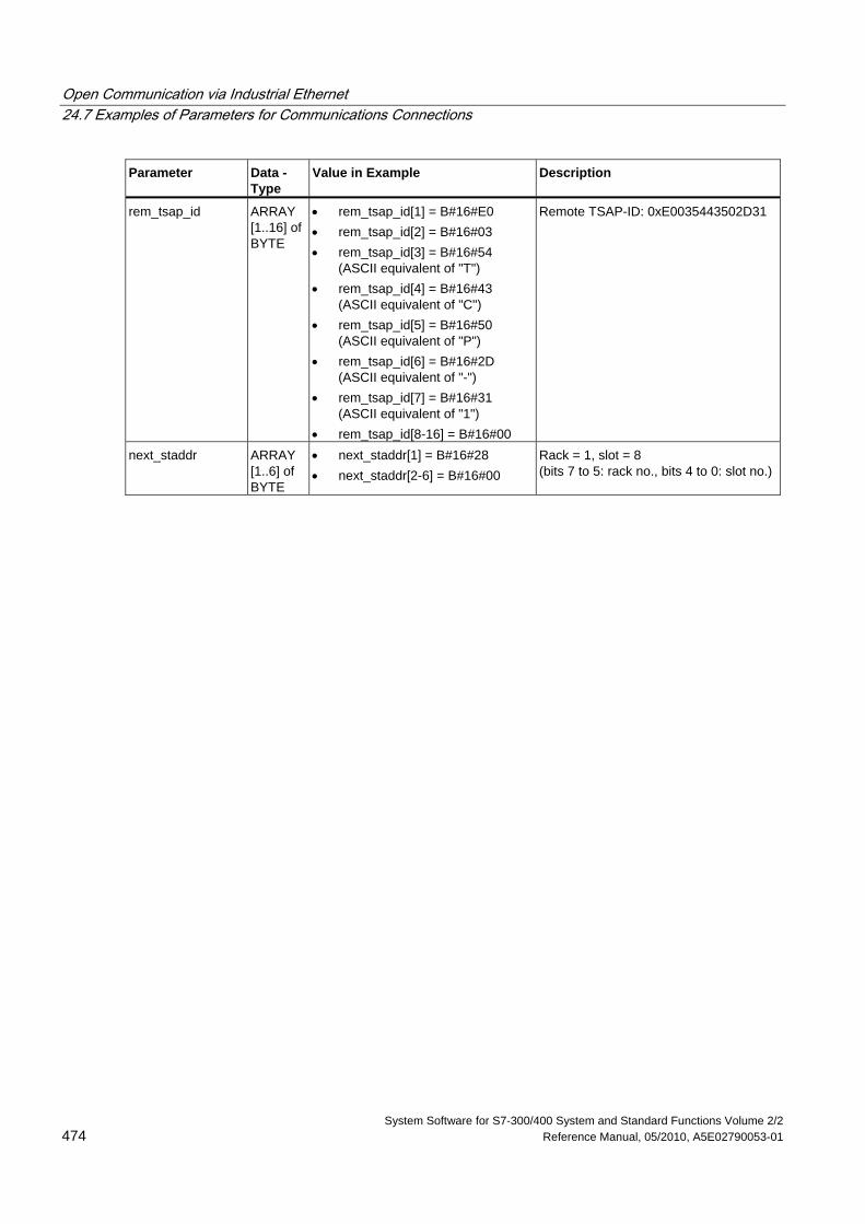
Open Communication via Industrial Ethernet 24.7 Examples of Parameters for Communications Connections
System Software for S7-300/400 System and Standard Functions Volume 2/2 474 Reference Manual, 05/2010, A5E02790053-01
Parameter Data - Type
Value in Example Description
rem_tsap_id ARRAY [1..16] of BYTE
• rem_tsap_id[1] = B#16#E0 • rem_tsap_id[2] = B#16#03 • rem_tsap_id[3] = B#16#54
(ASCII equivalent of "T") • rem_tsap_id[4] = B#16#43
(ASCII equivalent of "C") • rem_tsap_id[5] = B#16#50
(ASCII equivalent of "P") • rem_tsap_id[6] = B#16#2D
(ASCII equivalent of "-") • rem_tsap_id[7] = B#16#31
(ASCII equivalent of "1") • rem_tsap_id[8-16] = B#16#00
Remote TSAP-ID: 0xE0035443502D31
next_staddr ARRAY [1..6] of BYTE
• next_staddr[1] = B#16#28 • next_staddr[2-6] = B#16#00
Rack = 1, slot = 8 (bits 7 to 5: rack no., bits 4 to 0: slot no.)
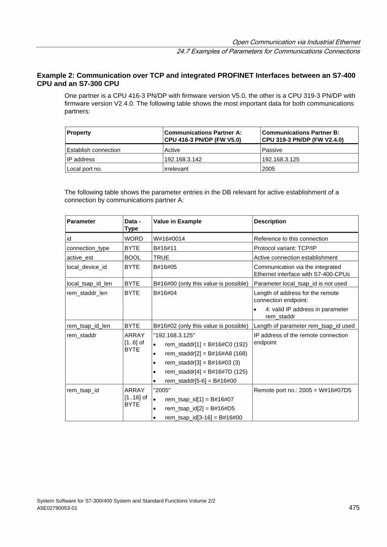
Open Communication via Industrial Ethernet 24.7 Examples of Parameters for Communications Connections
System Software for S7-300/400 System and Standard Functions Volume 2/2 A5E02790053-01 475
Example 2: Communication over TCP and integrated PROFINET Interfaces between an S7-400 CPU and an S7-300 CPU
One partner is a CPU 416-3 PN/DP with firmware version V5.0, the other is a CPU 319-3 PN/DP with firmware version V2.4.0. The following table shows the most important data for both communications partners:
Property Communications Partner A:
CPU 416-3 PN/DP (FW V5.0) Communications Partner B: CPU 319-3 PN/DP (FW V2.4.0)
Establish connection Active Passive IP address 192.168.3.142 192.168.3.125 Local port no. irrelevant 2005
The following table shows the parameter entries in the DB relevant for active establishment of a connection by communications partner A:
Parameter Data -
Type Value in Example Description
id WORD W#16#0014 Reference to this connection connection_type BYTE B#16#11 Protocol variant: TCP/IP active_est BOOL TRUE Active connection establishment local_device_id BYTE B#16#05 Communication via the integrated
Ethernet interface with S7-400-CPUs local_tsap_id_len BYTE B#16#00 (only this value is possible) Parameter local_tsap_id is not used rem_staddr_len BYTE B#16#04 Length of address for the remote
connection endpoint: • 4: valid IP address in parameter
rem_staddr rem_tsap_id_len BYTE B#16#02 (only this value is possible) Length of parameter rem_tsap_id used rem_staddr ARRAY
[1..6] of BYTE
"192.168.3.125" • rem_staddr[1] = B#16#C0 (192) • rem_staddr[2] = B#16#A8 (168) • rem_staddr[3] = B#16#03 (3) • rem_staddr[4] = B#16#7D (125) • rem_staddr[5-6] = B#16#00
IP address of the remote connection endpoint
rem_tsap_id ARRAY [1..16] of BYTE
"2005" • rem_tsap_id[1] = B#16#07 • rem_tsap_id[2] = B#16#D5 • rem_tsap_id[3-16] = B#16#00
Remote port no.: 2005 = W#16#07D5
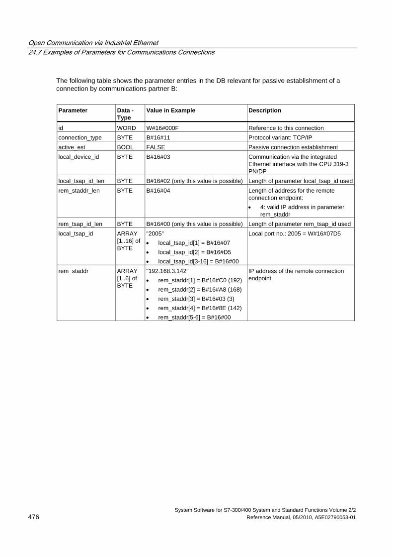
Open Communication via Industrial Ethernet 24.7 Examples of Parameters for Communications Connections
System Software for S7-300/400 System and Standard Functions Volume 2/2 476 Reference Manual, 05/2010, A5E02790053-01
The following table shows the parameter entries in the DB relevant for passive establishment of a connection by communications partner B:
Parameter Data -
Type Value in Example Description
id WORD W#16#000F Reference to this connection connection_type BYTE B#16#11 Protocol variant: TCP/IP active_est BOOL FALSE Passive connection establishment local_device_id BYTE B#16#03 Communication via the integrated
Ethernet interface with the CPU 319-3 PN/DP
local_tsap_id_len BYTE B#16#02 (only this value is possible) Length of parameter local_tsap_id usedrem_staddr_len BYTE B#16#04 Length of address for the remote
connection endpoint: • 4: valid IP address in parameter
rem_staddr rem_tsap_id_len BYTE B#16#00 (only this value is possible) Length of parameter rem_tsap_id used local_tsap_id ARRAY
[1..16] of BYTE
"2005" • local_tsap_id[1] = B#16#07 • local_tsap_id[2] = B#16#D5 • local_tsap_id[3-16] = B#16#00
Local port no.: 2005 = W#16#07D5
rem_staddr ARRAY [1..6] of BYTE
"192.168.3.142" • rem_staddr[1] = B#16#C0 (192) • rem_staddr[2] = B#16#A8 (168) • rem_staddr[3] = B#16#03 (3) • rem_staddr[4] = B#16#8E (142) • rem_staddr[5-6] = B#16#00
IP address of the remote connection endpoint
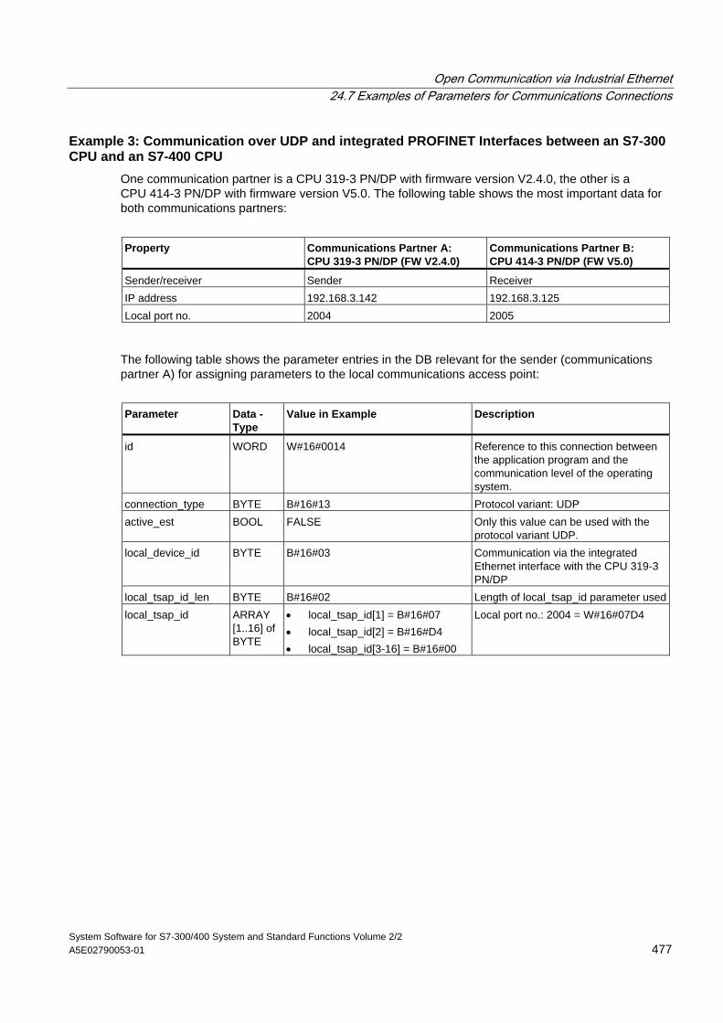
Open Communication via Industrial Ethernet 24.7 Examples of Parameters for Communications Connections
System Software for S7-300/400 System and Standard Functions Volume 2/2 A5E02790053-01 477
Example 3: Communication over UDP and integrated PROFINET Interfaces between an S7-300 CPU and an S7-400 CPU
One communication partner is a CPU 319-3 PN/DP with firmware version V2.4.0, the other is a CPU 414-3 PN/DP with firmware version V5.0. The following table shows the most important data for both communications partners:
Property Communications Partner A:
CPU 319-3 PN/DP (FW V2.4.0) Communications Partner B: CPU 414-3 PN/DP (FW V5.0)
Sender/receiver Sender Receiver IP address 192.168.3.142 192.168.3.125 Local port no. 2004 2005
The following table shows the parameter entries in the DB relevant for the sender (communications partner A) for assigning parameters to the local communications access point:
Parameter Data -
Type Value in Example Description
id WORD W#16#0014 Reference to this connection between the application program and the communication level of the operating system.
connection_type BYTE B#16#13 Protocol variant: UDP active_est BOOL FALSE Only this value can be used with the
protocol variant UDP. local_device_id BYTE B#16#03 Communication via the integrated
Ethernet interface with the CPU 319-3 PN/DP
local_tsap_id_len BYTE B#16#02 Length of local_tsap_id parameter usedlocal_tsap_id ARRAY
[1..16] of BYTE
• local_tsap_id[1] = B#16#07 • local_tsap_id[2] = B#16#D4 • local_tsap_id[3-16] = B#16#00
Local port no.: 2004 = W#16#07D4
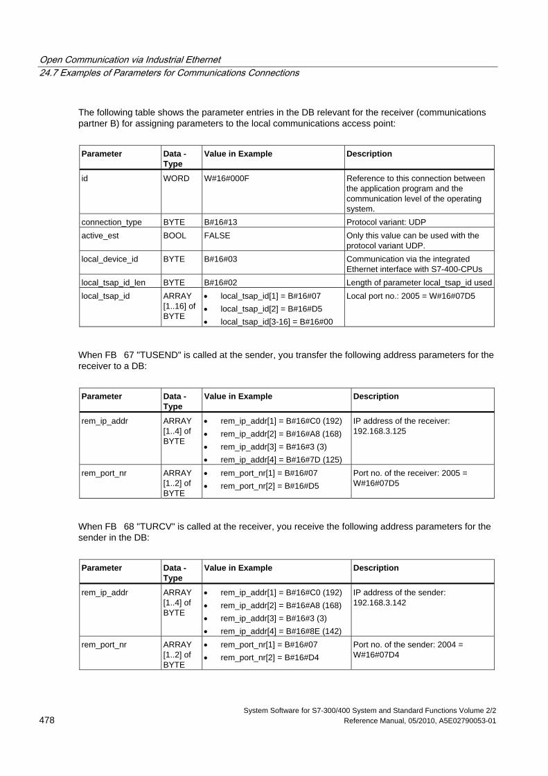
Open Communication via Industrial Ethernet 24.7 Examples of Parameters for Communications Connections
System Software for S7-300/400 System and Standard Functions Volume 2/2 478 Reference Manual, 05/2010, A5E02790053-01
The following table shows the parameter entries in the DB relevant for the receiver (communications partner B) for assigning parameters to the local communications access point:
Parameter Data -
Type Value in Example Description
id WORD W#16#000F Reference to this connection between the application program and the communication level of the operating system.
connection_type BYTE B#16#13 Protocol variant: UDP active_est BOOL FALSE Only this value can be used with the
protocol variant UDP. local_device_id BYTE B#16#03 Communication via the integrated
Ethernet interface with S7-400-CPUs local_tsap_id_len BYTE B#16#02 Length of parameter local_tsap_id usedlocal_tsap_id ARRAY
[1..16] of BYTE
• local_tsap_id[1] = B#16#07 • local_tsap_id[2] = B#16#D5 • local_tsap_id[3-16] = B#16#00
Local port no.: 2005 = W#16#07D5
When FB 67 "TUSEND" is called at the sender, you transfer the following address parameters for the receiver to a DB:
Parameter Data -
Type Value in Example Description
rem_ip_addr ARRAY [1..4] of BYTE
• rem_ip_addr[1] = B#16#C0 (192) • rem_ip_addr[2] = B#16#A8 (168) • rem_ip_addr[3] = B#16#3 (3) • rem_ip_addr[4] = B#16#7D (125)
IP address of the receiver: 192.168.3.125
rem_port_nr ARRAY [1..2] of BYTE
• rem_port_nr[1] = B#16#07 • rem_port_nr[2] = B#16#D5
Port no. of the receiver: 2005 = W#16#07D5
When FB 68 "TURCV" is called at the receiver, you receive the following address parameters for the sender in the DB:
Parameter Data -
Type Value in Example Description
rem_ip_addr ARRAY [1..4] of BYTE
• rem_ip_addr[1] = B#16#C0 (192) • rem_ip_addr[2] = B#16#A8 (168) • rem_ip_addr[3] = B#16#3 (3) • rem_ip_addr[4] = B#16#8E (142)
IP address of the sender: 192.168.3.142
rem_port_nr ARRAY [1..2] of BYTE
• rem_port_nr[1] = B#16#07 • rem_port_nr[2] = B#16#D4
Port no. of the sender: 2004 = W#16#07D4
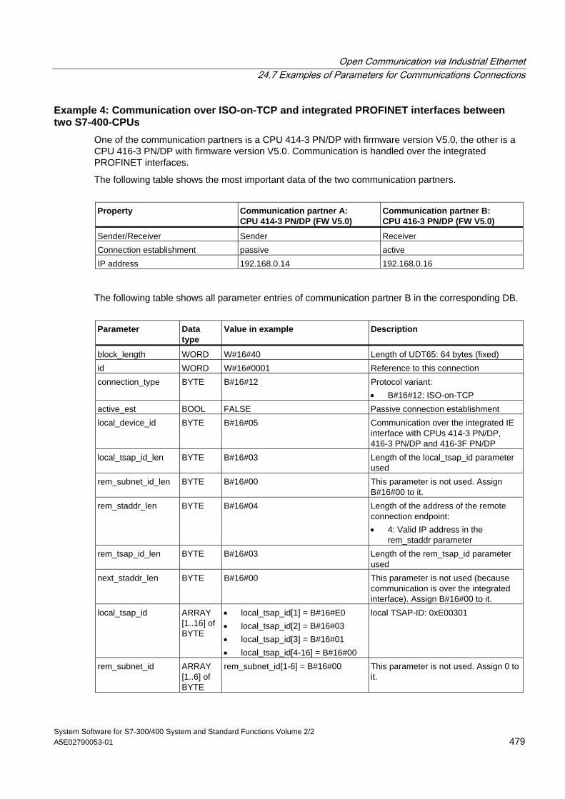
Open Communication via Industrial Ethernet 24.7 Examples of Parameters for Communications Connections
System Software for S7-300/400 System and Standard Functions Volume 2/2 A5E02790053-01 479
Example 4: Communication over ISO-on-TCP and integrated PROFINET interfaces between two S7-400-CPUs
One of the communication partners is a CPU 414-3 PN/DP with firmware version V5.0, the other is a CPU 416-3 PN/DP with firmware version V5.0. Communication is handled over the integrated PROFINET interfaces.
The following table shows the most important data of the two communication partners.
Property Communication partner A:
CPU 414-3 PN/DP (FW V5.0) Communication partner B: CPU 416-3 PN/DP (FW V5.0)
Sender/Receiver Sender Receiver Connection establishment passive active IP address 192.168.0.14 192.168.0.16
The following table shows all parameter entries of communication partner B in the corresponding DB.
Parameter Data
type Value in example Description
block_length WORD W#16#40 Length of UDT65: 64 bytes (fixed) id WORD W#16#0001 Reference to this connection connection_type BYTE B#16#12 Protocol variant:
• B#16#12: ISO-on-TCP active_est BOOL FALSE Passive connection establishment local_device_id BYTE B#16#05 Communication over the integrated IE
interface with CPUs 414-3 PN/DP, 416-3 PN/DP and 416-3F PN/DP
local_tsap_id_len BYTE B#16#03 Length of the local_tsap_id parameter used
rem_subnet_id_len BYTE B#16#00 This parameter is not used. Assign B#16#00 to it.
rem_staddr_len BYTE B#16#04 Length of the address of the remote connection endpoint: • 4: Valid IP address in the
rem_staddr parameter rem_tsap_id_len BYTE B#16#03 Length of the rem_tsap_id parameter
used next_staddr_len BYTE B#16#00 This parameter is not used (because
communication is over the integrated interface). Assign B#16#00 to it.
local_tsap_id ARRAY [1..16] of BYTE
• local_tsap_id[1] = B#16#E0 • local_tsap_id[2] = B#16#03 • local_tsap_id[3] = B#16#01 • local_tsap_id[4-16] = B#16#00
local TSAP-ID: 0xE00301
rem_subnet_id ARRAY [1..6] of BYTE
rem_subnet_id[1-6] = B#16#00 This parameter is not used. Assign 0 to it.
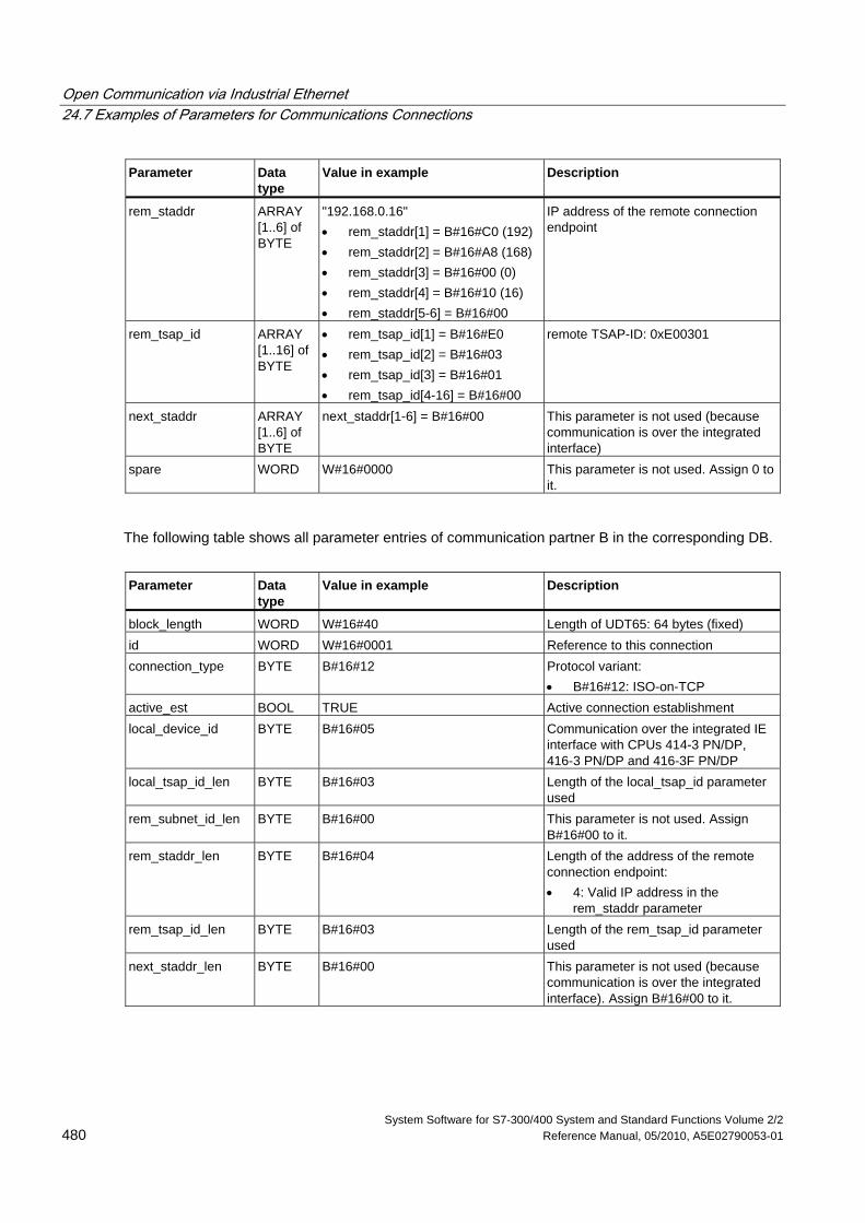
Open Communication via Industrial Ethernet 24.7 Examples of Parameters for Communications Connections
System Software for S7-300/400 System and Standard Functions Volume 2/2 480 Reference Manual, 05/2010, A5E02790053-01
Parameter Data type
Value in example Description
rem_staddr ARRAY [1..6] of BYTE
"192.168.0.16" • rem_staddr[1] = B#16#C0 (192) • rem_staddr[2] = B#16#A8 (168) • rem_staddr[3] = B#16#00 (0) • rem_staddr[4] = B#16#10 (16) • rem_staddr[5-6] = B#16#00
IP address of the remote connection endpoint
rem_tsap_id ARRAY [1..16] of BYTE
• rem_tsap_id[1] = B#16#E0 • rem_tsap_id[2] = B#16#03 • rem_tsap_id[3] = B#16#01 • rem_tsap_id[4-16] = B#16#00
remote TSAP-ID: 0xE00301
next_staddr ARRAY [1..6] of BYTE
next_staddr[1-6] = B#16#00 This parameter is not used (because communication is over the integrated interface)
spare WORD W#16#0000 This parameter is not used. Assign 0 to it.
The following table shows all parameter entries of communication partner B in the corresponding DB.
Parameter Data
type Value in example Description
block_length WORD W#16#40 Length of UDT65: 64 bytes (fixed) id WORD W#16#0001 Reference to this connection connection_type BYTE B#16#12 Protocol variant:
• B#16#12: ISO-on-TCP active_est BOOL TRUE Active connection establishment local_device_id BYTE B#16#05 Communication over the integrated IE
interface with CPUs 414-3 PN/DP, 416-3 PN/DP and 416-3F PN/DP
local_tsap_id_len BYTE B#16#03 Length of the local_tsap_id parameter used
rem_subnet_id_len BYTE B#16#00 This parameter is not used. Assign B#16#00 to it.
rem_staddr_len BYTE B#16#04 Length of the address of the remote connection endpoint: • 4: Valid IP address in the
rem_staddr parameter rem_tsap_id_len BYTE B#16#03 Length of the rem_tsap_id parameter
used next_staddr_len BYTE B#16#00 This parameter is not used (because
communication is over the integrated interface). Assign B#16#00 to it.
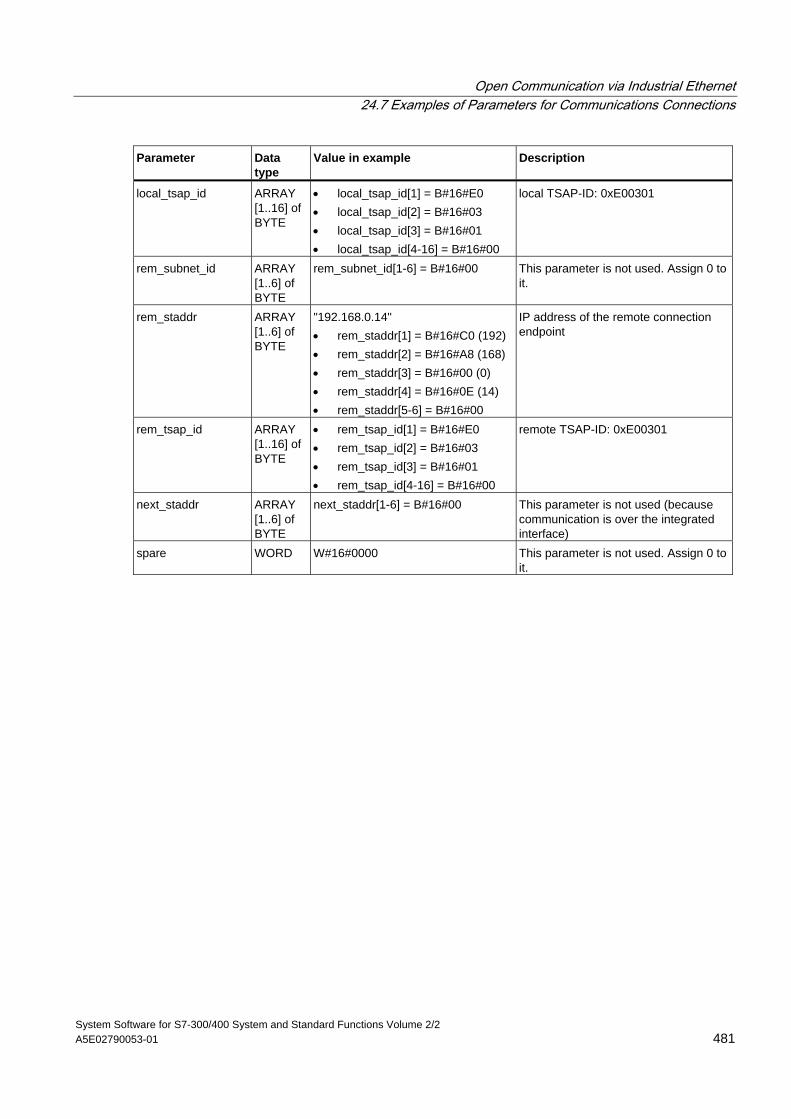
Open Communication via Industrial Ethernet 24.7 Examples of Parameters for Communications Connections
System Software for S7-300/400 System and Standard Functions Volume 2/2 A5E02790053-01 481
Parameter Data type
Value in example Description
local_tsap_id ARRAY [1..16] of BYTE
• local_tsap_id[1] = B#16#E0 • local_tsap_id[2] = B#16#03 • local_tsap_id[3] = B#16#01 • local_tsap_id[4-16] = B#16#00
local TSAP-ID: 0xE00301
rem_subnet_id ARRAY [1..6] of BYTE
rem_subnet_id[1-6] = B#16#00 This parameter is not used. Assign 0 to it.
rem_staddr ARRAY [1..6] of BYTE
"192.168.0.14" • rem_staddr[1] = B#16#C0 (192) • rem_staddr[2] = B#16#A8 (168) • rem_staddr[3] = B#16#00 (0) • rem_staddr[4] = B#16#0E (14) • rem_staddr[5-6] = B#16#00
IP address of the remote connection endpoint
rem_tsap_id ARRAY [1..16] of BYTE
• rem_tsap_id[1] = B#16#E0 • rem_tsap_id[2] = B#16#03 • rem_tsap_id[3] = B#16#01 • rem_tsap_id[4-16] = B#16#00
remote TSAP-ID: 0xE00301
next_staddr ARRAY [1..6] of BYTE
next_staddr[1-6] = B#16#00 This parameter is not used (because communication is over the integrated interface)
spare WORD W#16#0000 This parameter is not used. Assign 0 to it.
Open Communication via Industrial Ethernet 24.8 Establishing a Connection with FB 65 "TCON"
System Software for S7-300/400 System and Standard Functions Volume 2/2 482 Reference Manual, 05/2010, A5E02790053-01
24.8 Establishing a Connection with FB 65 "TCON"
For information on the number of possible connections, please refer to the technical data for your CPU.
Use with TCP and ISO on TCP Both communications partners call FB 65 "TCON" to set up and establish the communications connection. In the parameters you specify which partner is the active communications transmission point and which is the passive one.
After the connection is set up and established, it is automatically maintained and monitored by the CPU.
If the connection is interrupted, such as due a line break or due to the remote communications partner, the active partner attempts to reestablish the configured connection. In this case, you do not have to call FB 65 "TCON" again.
An existing connection is terminated and the configured connection is removed when FB 66 "TDISCON" is called or when the CPU has gone into STOP mode. To set up again and reestablish the connection, you will have to call FB 65 "TCON" again.
Use with UDP Both communications partner call FB 65 "TCON" in order to configure their local communications access point (local port). A connection is configured between the user program and the communications level of the operating system. No connection is established to the remote partner.
The local access point is used to send and receive UDP message frames.
When assigning parameters for the local access point (UDT65) or assigning parameters to the remote partner (UDT66), the following parameters must be the same.
• For UDP: reference to the connection and local port number
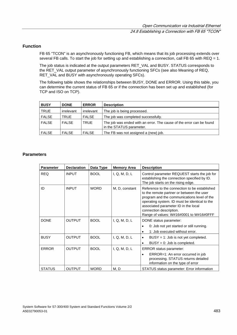
Open Communication via Industrial Ethernet 24.8 Establishing a Connection with FB 65 "TCON"
System Software for S7-300/400 System and Standard Functions Volume 2/2 A5E02790053-01 483
Function FB 65 "TCON" is an asynchronously functioning FB, which means that its job processing extends over several FB calls. To start the job for setting up and establishing a connection, call FB 65 with REQ = 1.
The job status is indicated at the output parameters RET_VAL and BUSY. STATUS corresponds to the RET_VAL output parameter of asynchronously functioning SFCs (see also Meaning of REQ, RET_VAL and BUSY with asynchronously operating SFCs).
The following table shows the relationships between BUSY, DONE and ERROR. Using this table, you can determine the current status of FB 65 or if the connection has been set up and established (for TCP and ISO on TCP).
BUSY DONE ERROR Description
TRUE irrelevant irrelevant The job is being processed. FALSE TRUE FALSE The job was completed successfully. FALSE FALSE TRUE The job was ended with an error. The cause of the error can be found
in the STATUS parameter. FALSE FALSE FALSE The FB was not assigned a (new) job.
Parameters Parameter Declaration Data Type Memory Area Description
REQ INPUT BOOL I, Q, M, D, L Control parameter REQUEST starts the job for establishing the connection specified by ID. The job starts on the rising edge.
ID INPUT WORD M, D, constant Reference to the connection to be established to the remote partner or between the user program and the communications level of the operating system. ID must be identical to the associated parameter ID in the local connection description. Range of values: W#16#0001 to W#16#0FFF
DONE OUTPUT BOOL I, Q, M, D, L DONE status parameter: • 0: Job not yet started or still running. • 1: Job executed without error.
BUSY OUTPUT BOOL I, Q, M, D, L • BUSY = 1: Job is not yet completed. • BUSY = 0: Job is completed.
ERROR OUTPUT BOOL I, Q, M, D, L ERROR status parameter: • ERROR=1: An error occurred in job
processing. STATUS returns detailed information on the type of error
STATUS OUTPUT WORD M, D STATUS status parameter: Error information
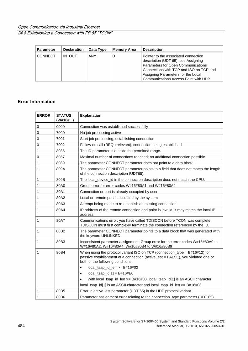
Open Communication via Industrial Ethernet 24.8 Establishing a Connection with FB 65 "TCON"
System Software for S7-300/400 System and Standard Functions Volume 2/2 484 Reference Manual, 05/2010, A5E02790053-01
Parameter Declaration Data Type Memory Area Description
CONNECT IN_OUT ANY D Pointer to the associated connection description (UDT 65), see Assigning Parameters for Open Communications Connections with TCP and ISO on TCP and Assigning Parameters for the Local Communications Access Point with UDP
Error Information ERROR STATUS
(W#16#...) Explanation
0 0000 Connection was established successfully 0 7000 No job processing active 0 7001 Start job processing, establishing connection 0 7002 Follow-on call (REQ irrelevant), connection being established 1 8086 The ID parameter is outside the permitted range. 0 8087 Maximal number of connections reached; no additional connection possible 1 8089 The parameter CONNECT parameter does not point to a data block. 1 809A The parameter CONNECT parameter points to a field that does not match the length
of the connection description (UDT65). 1 809B The local_device_id in the connection description does not match the CPU. 1 80A0 Group error for error codes W#16#80A1 and W#16#80A2 1 80A1 Connection or port is already occupied by user 1 80A2 Local or remote port is occupied by the system 1 80A3 Attempt being made to re-establish an existing connection 1 80A4 IP address of the remote connection end point is invalid, it may match the local IP
address 1 80A7 Communications error: you have called TDISCON before TCON was complete.
TDISCON must first complexly terminate the connection referenced by the ID. 1 80B2 The parameter CONNECT parameter points to a data block that was generated with
the keyword UNLINKED. 1 80B3 Inconsistent parameter assignment: Group error for the error codes W#16#80A0 to
W#16#80A2, W#16#80A4, W#16#80B4 to W#16#80B9 1 80B4 When using the protocol variant ISO on TCP (connection_type = B#16#12) for
passive establishment of a connection (active_est = FALSE), you violated one or both of the following conditions: • local_tsap_id_len >= B#16#02 • local_tsap_id[1] = B#16#E0 • With local_tsap_id_len >= B#16#03, local_tsap_id[1] is an ASCII character local_tsap_id[1] is an ASCII character and local_tsap_id_len >= B#16#03
1 80B5 Error in active_est parameter (UDT 65) in the UDP protocol variant 1 80B6 Parameter assignment error relating to the connection_type parameter (UDT 65)
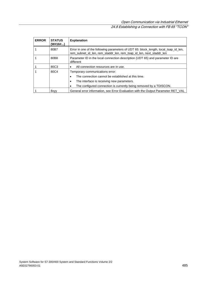
Open Communication via Industrial Ethernet 24.8 Establishing a Connection with FB 65 "TCON"
System Software for S7-300/400 System and Standard Functions Volume 2/2 A5E02790053-01 485
ERROR STATUS (W#16#...)
Explanation
1 80B7 Error in one of the following parameters of UDT 65: block_length, local_tsap_id_len, rem_subnet_id_len, rem_staddr_len, rem_tsap_id_len, next_staddr_len
1 80B8 Parameter ID in the local connection description (UDT 65) and parameter ID are different
1 80C3 • All connection resources are in use. 1 80C4 Temporary communications error:
• The connection cannot be established at this time. • The interface is receiving new parameters. • The configured connection is currently being removed by a TDISCON.
1 8xyy General error information, see Error Evaluation with the Output Parameter RET_VAL
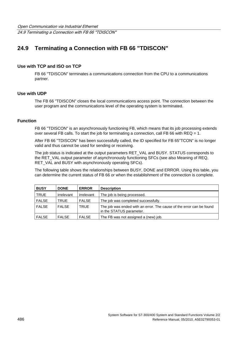
Open Communication via Industrial Ethernet 24.9 Terminating a Connection with FB 66 "TDISCON"
System Software for S7-300/400 System and Standard Functions Volume 2/2 486 Reference Manual, 05/2010, A5E02790053-01
24.9 Terminating a Connection with FB 66 "TDISCON"
Use with TCP and ISO on TCP FB 66 "TDISCON" terminates a communications connection from the CPU to a communications partner.
Use with UDP The FB 66 "TDISCON" closes the local communications access point. The connection between the user program and the communications level of the operating system is terminated.
Function FB 66 "TDISCON" is an asynchronously functioning FB, which means that its job processing extends over several FB calls. To start the job for terminating a connection, call FB 66 with REQ = 1.
After FB 66 "TDISCON" has been successfully called, the ID specified for FB 65"TCON" is no longer valid and thus cannot be used for sending or receiving.
The job status is indicated at the output parameters RET_VAL and BUSY. STATUS corresponds to the RET_VAL output parameter of asynchronously functioning SFCs (see also Meaning of REQ, RET_VAL and BUSY with asynchronously operating SFCs).
The following table shows the relationships between BUSY, DONE and ERROR. Using this table, you can determine the current status of FB 66 or when the establishment of the connection is complete.
BUSY DONE ERROR Description
TRUE irrelevant irrelevant The job is being processed. FALSE TRUE FALSE The job was completed successfully. FALSE FALSE TRUE The job was ended with an error. The cause of the error can be found
in the STATUS parameter. FALSE FALSE FALSE The FB was not assigned a (new) job.
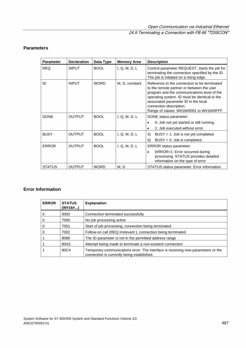
Open Communication via Industrial Ethernet 24.9 Terminating a Connection with FB 66 "TDISCON"
System Software for S7-300/400 System and Standard Functions Volume 2/2 A5E02790053-01 487
Parameters Parameter Declaration Data Type Memory Area Description
REQ INPUT BOOL I, Q, M, D, L Control parameter REQUEST, starts the job for terminating the connection specified by the ID. The job is initiated on a rising edge.
ID INPUT WORD M, D, constant Reference to the connection to be terminated to the remote partner or between the user program and the communications level of the operating system. ID must be identical to the associated parameter ID in the local connection description. Range of values: W#16#0001 to W#16#0FFF
DONE OUTPUT BOOL I, Q, M, D, L DONE status parameter: • 0: Job not yet started or still running. • 1: Job executed without error.
BUSY OUTPUT BOOL I, Q, M, D, L 5) BUSY = 1: Job is not yet completed. 6) BUSY = 0: Job is completed.
ERROR OUTPUT BOOL I, Q, M, D, L ERROR status parameter: • ERROR=1: Error occurred during
processing. STATUS provides detailed information on the type of error
STATUS OUTPUT WORD M, D STATUS status parameter: Error information
Error Information ERROR STATUS
(W#16#...) Explanation
0 0000 Connection terminated successfully 0 7000 No job processing active 0 7001 Start of job processing, connection being terminated 0 7002 Follow-on call (REQ irrelevant ), connection being terminated 1 8086 The ID parameter is not in the permitted address range 1 80A3 Attempt being made to terminate a non-existent connection 1 80C4 Temporary communications error: The interface is receiving new parameters or the
connection is currently being established.
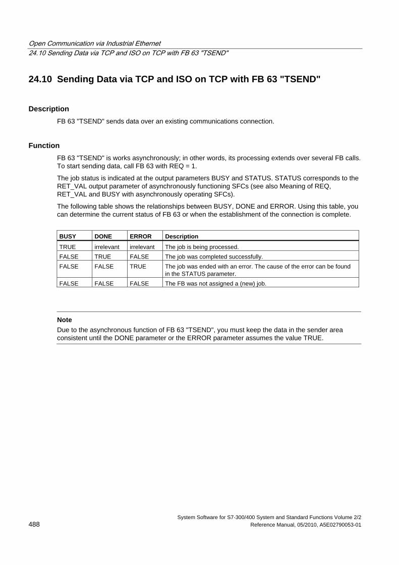
Open Communication via Industrial Ethernet 24.10 Sending Data via TCP and ISO on TCP with FB 63 "TSEND"
System Software for S7-300/400 System and Standard Functions Volume 2/2 488 Reference Manual, 05/2010, A5E02790053-01
24.10 Sending Data via TCP and ISO on TCP with FB 63 "TSEND"
Description FB 63 "TSEND" sends data over an existing communications connection.
Function FB 63 "TSEND" is works asynchronously; in other words, its processing extends over several FB calls. To start sending data, call FB 63 with REQ = 1.
The job status is indicated at the output parameters BUSY and STATUS. STATUS corresponds to the RET_VAL output parameter of asynchronously functioning SFCs (see also Meaning of REQ, RET_VAL and BUSY with asynchronously operating SFCs).
The following table shows the relationships between BUSY, DONE and ERROR. Using this table, you can determine the current status of FB 63 or when the establishment of the connection is complete.
BUSY DONE ERROR Description
TRUE irrelevant irrelevant The job is being processed. FALSE TRUE FALSE The job was completed successfully. FALSE FALSE TRUE The job was ended with an error. The cause of the error can be found
in the STATUS parameter. FALSE FALSE FALSE The FB was not assigned a (new) job.
Note
Due to the asynchronous function of FB 63 "TSEND", you must keep the data in the sender area consistent until the DONE parameter or the ERROR parameter assumes the value TRUE.
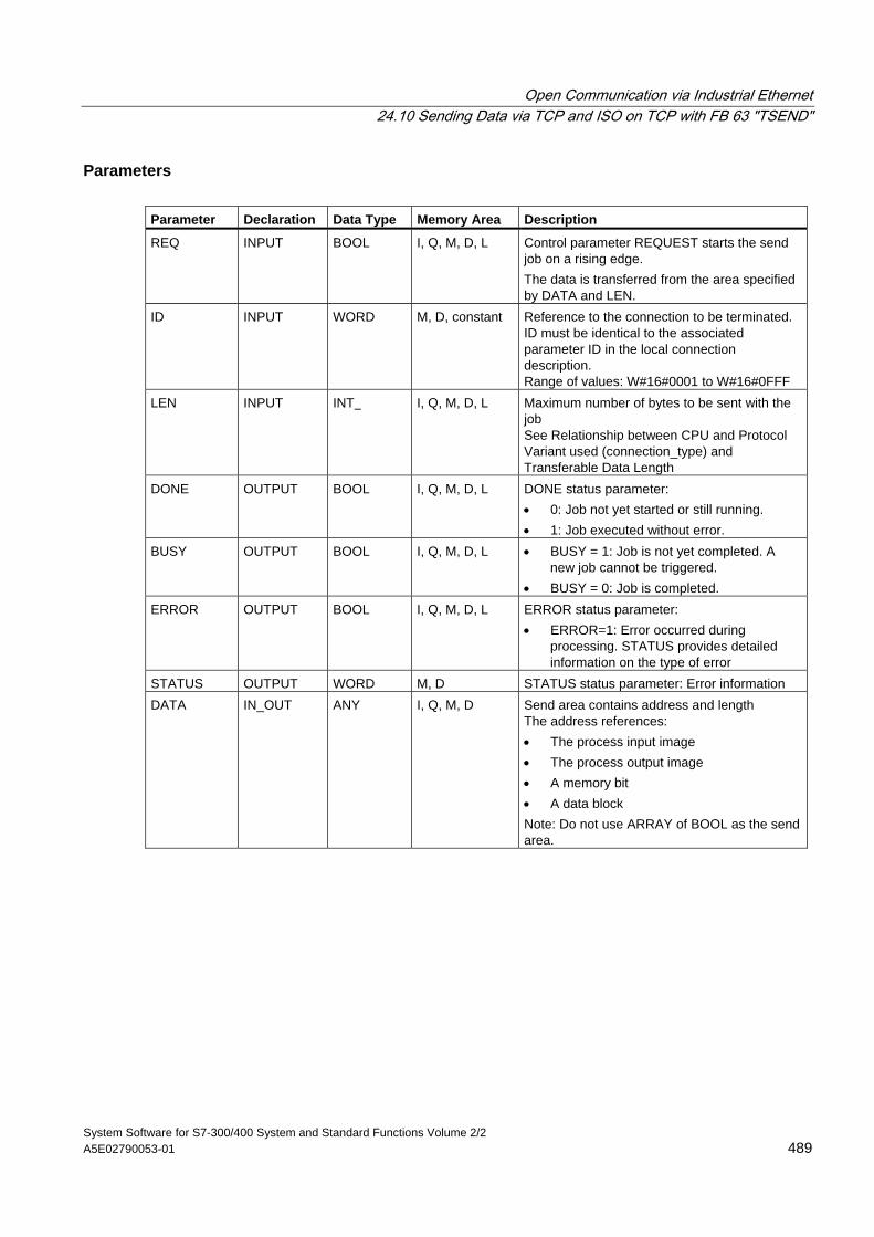
Open Communication via Industrial Ethernet 24.10 Sending Data via TCP and ISO on TCP with FB 63 "TSEND"
System Software for S7-300/400 System and Standard Functions Volume 2/2 A5E02790053-01 489
Parameters Parameter Declaration Data Type Memory Area Description
REQ INPUT BOOL I, Q, M, D, L Control parameter REQUEST starts the send job on a rising edge. The data is transferred from the area specified by DATA and LEN.
ID INPUT WORD M, D, constant Reference to the connection to be terminated. ID must be identical to the associated parameter ID in the local connection description. Range of values: W#16#0001 to W#16#0FFF
LEN INPUT INT I, Q, M, D, L Maximum number of bytes to be sent with the job See Relationship between CPU and Protocol Variant used (connection_type) and Transferable Data Length
DONE OUTPUT BOOL I, Q, M, D, L DONE status parameter: • 0: Job not yet started or still running. • 1: Job executed without error.
BUSY OUTPUT BOOL I, Q, M, D, L • BUSY = 1: Job is not yet completed. A new job cannot be triggered.
• BUSY = 0: Job is completed. ERROR OUTPUT BOOL I, Q, M, D, L ERROR status parameter:
• ERROR=1: Error occurred during processing. STATUS provides detailed information on the type of error
STATUS OUTPUT WORD M, D STATUS status parameter: Error information DATA IN_OUT ANY I, Q, M, D Send area contains address and length
The address references: • The process input image • The process output image • A memory bit • A data block Note: Do not use ARRAY of BOOL as the send area.
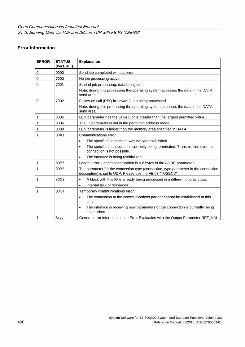
Open Communication via Industrial Ethernet 24.10 Sending Data via TCP and ISO on TCP with FB 63 "TSEND"
System Software for S7-300/400 System and Standard Functions Volume 2/2 490 Reference Manual, 05/2010, A5E02790053-01
Error Information ERROR STATUS
(W#16#...) Explanation
0 0000 Send job completed without error 0 7000 No job processing active 0 7001 Start of job processing, data being sent
Note: during this processing the operating system accesses the data in the DATA send area.
0 7002 Follow-on call (REQ irrelevant ), job being processed Note: during this processing the operating system accesses the data in the DATA send area.
1 8085 LEN parameter has the value 0 or is greater than the largest permitted value 1 8086 The ID parameter is not in the permitted address range 1 8088 LEN parameter is larger than the memory area specified in DATA 1 80A1 Communications error:
• The specified connection was not yet established • The specified connection is currently being terminated. Transmission over this
connection is not possible. • The interface is being reinitialized.
1 80B7 Length error: Length specification is < 8 bytes in the ADDR parameter. 1 80B3 The parameter for the connection type (connection_type parameter in the connection
description) is set to UDP. Please use the FB 67 "TUSEND". 1 80C3 • A block with this ID is already being processed in a different priority class.
• Internal lack of resources 1 80C4 Temporary communications error:
• The connection to the communications partner cannot be established at this time.
• The interface is receiving new parameters or the connection is currently being established
1 8xyy General error information, see Error Evaluation with the Output Parameter RET_VAL
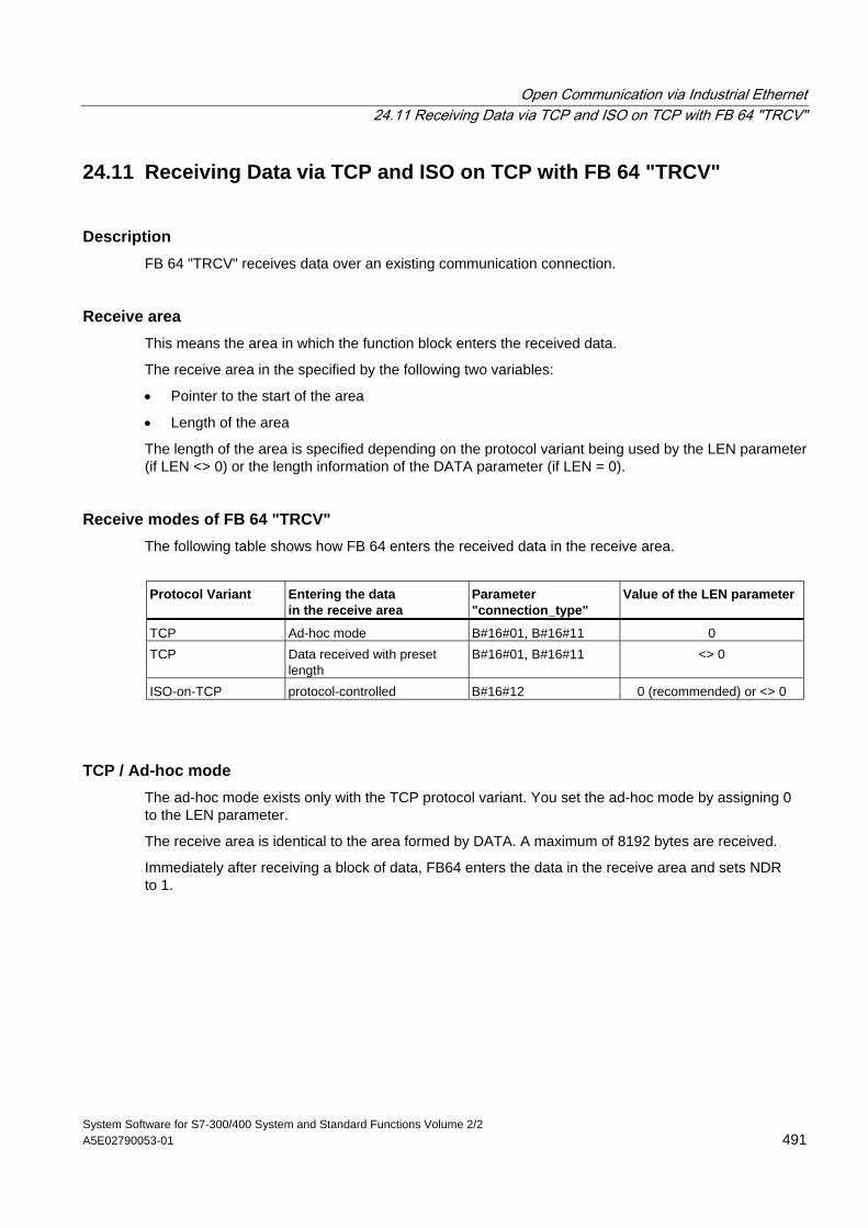
Open Communication via Industrial Ethernet 24.11 Receiving Data via TCP and ISO on TCP with FB 64 "TRCV"
System Software for S7-300/400 System and Standard Functions Volume 2/2 A5E02790053-01 491
24.11 Receiving Data via TCP and ISO on TCP with FB 64 "TRCV"
Description FB 64 "TRCV" receives data over an existing communication connection.
Receive area This means the area in which the function block enters the received data.
The receive area in the specified by the following two variables:
• Pointer to the start of the area
• Length of the area
The length of the area is specified depending on the protocol variant being used by the LEN parameter (if LEN <> 0) or the length information of the DATA parameter (if LEN = 0).
Receive modes of FB 64 "TRCV" The following table shows how FB 64 enters the received data in the receive area.
Protocol Variant Entering the data
in the receive area Parameter "connection_type"
Value of the LEN parameter
TCP Ad-hoc mode B#16#01, B#16#11 0 TCP Data received with preset
length B#16#01, B#16#11 <> 0
ISO-on-TCP protocol-controlled B#16#12 0 (recommended) or <> 0
TCP / Ad-hoc mode The ad-hoc mode exists only with the TCP protocol variant. You set the ad-hoc mode by assigning 0 to the LEN parameter.
The receive area is identical to the area formed by DATA. A maximum of 8192 bytes are received.
Immediately after receiving a block of data, FB64 enters the data in the receive area and sets NDR to 1.
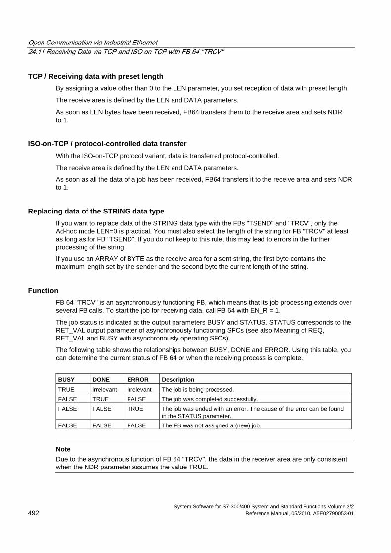
Open Communication via Industrial Ethernet 24.11 Receiving Data via TCP and ISO on TCP with FB 64 "TRCV"
System Software for S7-300/400 System and Standard Functions Volume 2/2 492 Reference Manual, 05/2010, A5E02790053-01
TCP / Receiving data with preset length By assigning a value other than 0 to the LEN parameter, you set reception of data with preset length.
The receive area is defined by the LEN and DATA parameters.
As soon as LEN bytes have been received, FB64 transfers them to the receive area and sets NDR to 1.
ISO-on-TCP / protocol-controlled data transfer With the ISO-on-TCP protocol variant, data is transferred protocol-controlled.
The receive area is defined by the LEN and DATA parameters.
As soon as all the data of a job has been received, FB64 transfers it to the receive area and sets NDR to 1.
Replacing data of the STRING data type If you want to replace data of the STRING data type with the FBs "TSEND" and "TRCV", only the Ad-hoc mode LEN=0 is practical. You must also select the length of the string for FB "TRCV" at least as long as for FB "TSEND". If you do not keep to this rule, this may lead to errors in the further processing of the string.
If you use an ARRAY of BYTE as the receive area for a sent string, the first byte contains the maximum length set by the sender and the second byte the current length of the string.
Function FB 64 "TRCV" is an asynchronously functioning FB, which means that its job processing extends over several FB calls. To start the job for receiving data, call FB 64 with EN_R = 1.
The job status is indicated at the output parameters BUSY and STATUS. STATUS corresponds to the RET_VAL output parameter of asynchronously functioning SFCs (see also Meaning of REQ, RET_VAL and BUSY with asynchronously operating SFCs).
The following table shows the relationships between BUSY, DONE and ERROR. Using this table, you can determine the current status of FB 64 or when the receiving process is complete.
BUSY DONE ERROR Description
TRUE irrelevant irrelevant The job is being processed. FALSE TRUE FALSE The job was completed successfully. FALSE FALSE TRUE The job was ended with an error. The cause of the error can be found
in the STATUS parameter. FALSE FALSE FALSE The FB was not assigned a (new) job.
Note
Due to the asynchronous function of FB 64 "TRCV", the data in the receiver area are only consistent when the NDR parameter assumes the value TRUE.
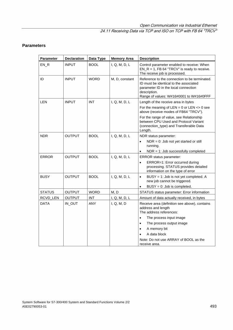
Open Communication via Industrial Ethernet 24.11 Receiving Data via TCP and ISO on TCP with FB 64 "TRCV"
System Software for S7-300/400 System and Standard Functions Volume 2/2 A5E02790053-01 493
Parameters Parameter Declaration Data Type Memory Area Description
EN_R INPUT BOOL I, Q, M, D, L Control parameter enabled to receive: When EN_R = 1, FB 64 "TRCV" is ready to receive. The receive job is processed.
ID INPUT WORD M, D, constant Reference to the connection to be terminated. ID must be identical to the associated parameter ID in the local connection description. Range of values: W#16#0001 to W#16#0FFF
LEN INPUT INT I, Q, M, D, L Length of the receive area in bytes For the meaning of LEN = 0 or LEN <> 0 see above (receive modes of FB64 "TRCV"). For the range of value, see Relationship between CPU Used and Protocol Variant (connection_type) and Transferable Data Length.
NDR OUTPUT BOOL I, Q, M, D, L NDR status parameter: • NDR = 0: Job not yet started or still
running. • NDR = 1: Job successfully completed
ERROR OUTPUT BOOL I, Q, M, D, L ERROR status parameter: • ERROR=1: Error occurred during
processing. STATUS provides detailed information on the type of error
BUSY OUTPUT BOOL I, Q, M, D, L • BUSY = 1: Job is not yet completed. A new job cannot be triggered.
• BUSY = 0: Job is completed. STATUS OUTPUT WORD M, D STATUS status parameter: Error information RCVD_LEN OUTPUT INT I, Q, M, D, L Amount of data actually received, in bytes DATA IN_OUT ANY I, Q, M, D Receive area (definition see above), contains
address and length The address references: • The process input image • The process output image • A memory bit • A data block Note: Do not use ARRAY of BOOL as the receive area.

Open Communication via Industrial Ethernet 24.11 Receiving Data via TCP and ISO on TCP with FB 64 "TRCV"
System Software for S7-300/400 System and Standard Functions Volume 2/2 494 Reference Manual, 05/2010, A5E02790053-01
Error Information ERROR STATUS
(W#16#...) Explanation
0 0000 New data were accepted. The current length of the received data is shown in RCVD_LEN.
0 7000 Block not ready to receive 0 7001 Block is ready to receive, receive job was activated. 0 7002 Follow-on call, receive job being processed
Note: during this processing the FB writes data to the receive area. For this reason, an error could result in inconsistent data in the receive area.
1 8085 LEN parameter is greater than the largest permitted value, or you changed the LEN or DATA parameter since the first call
1 8086 The ID parameter is not in the permitted address range 0 8088 • Receive area is too small
• Value in LEN is higher than the receive area specified by DATA 1 80A1 Communications error:
• The specified connection has not yet been established • The specified connection is currently being terminated. A receive job over this
connection is not possible. • The interface is receiving new parameters.
1 80B3 The parameter for the protocol variant (connection_type parameter in the connection description) is set to UDP. Please use the FB 68 "TRCV".
1 80C3 • A block with this ID is already being processed in a different priority class. • Internal lack of resources.
1 80C4 Temporary communications error: • The connection to the partner cannot be established at the moment. • The interface is receiving new parameter settings or the connection is currently
being established. 1 8xyy General error information, see Error Evaluation with the Output Parameter RET_VAL
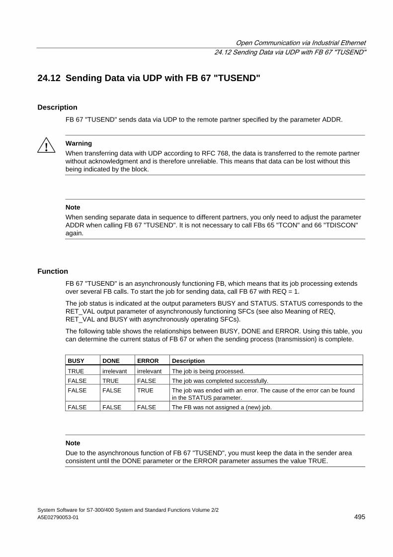
Open Communication via Industrial Ethernet 24.12 Sending Data via UDP with FB 67 "TUSEND"
System Software for S7-300/400 System and Standard Functions Volume 2/2 A5E02790053-01 495
24.12 Sending Data via UDP with FB 67 "TUSEND"
Description FB 67 "TUSEND" sends data via UDP to the remote partner specified by the parameter ADDR.
! Warning When transferring data with UDP according to RFC 768, the data is transferred to the remote partner without acknowledgment and is therefore unreliable. This means that data can be lost without this being indicated by the block.
Note
When sending separate data in sequence to different partners, you only need to adjust the parameter ADDR when calling FB 67 "TUSEND". It is not necessary to call FBs 65 "TCON" and 66 "TDISCON" again.
Function FB 67 "TUSEND" is an asynchronously functioning FB, which means that its job processing extends over several FB calls. To start the job for sending data, call FB 67 with REQ = 1.
The job status is indicated at the output parameters BUSY and STATUS. STATUS corresponds to the RET_VAL output parameter of asynchronously functioning SFCs (see also Meaning of REQ, RET_VAL and BUSY with asynchronously operating SFCs).
The following table shows the relationships between BUSY, DONE and ERROR. Using this table, you can determine the current status of FB 67 or when the sending process (transmission) is complete.
BUSY DONE ERROR Description
TRUE irrelevant irrelevant The job is being processed. FALSE TRUE FALSE The job was completed successfully. FALSE FALSE TRUE The job was ended with an error. The cause of the error can be found
in the STATUS parameter. FALSE FALSE FALSE The FB was not assigned a (new) job.
Note
Due to the asynchronous function of FB 67 "TUSEND", you must keep the data in the sender area consistent until the DONE parameter or the ERROR parameter assumes the value TRUE.
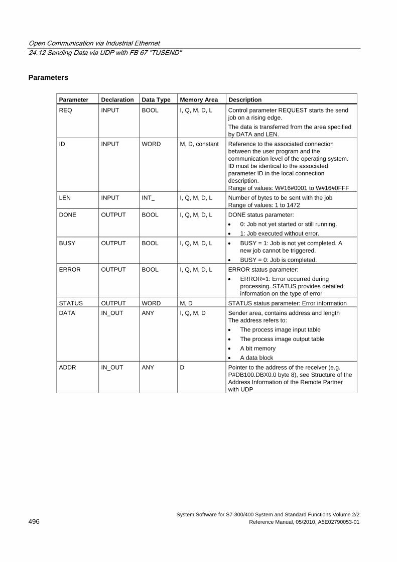
Open Communication via Industrial Ethernet 24.12 Sending Data via UDP with FB 67 "TUSEND"
System Software for S7-300/400 System and Standard Functions Volume 2/2 496 Reference Manual, 05/2010, A5E02790053-01
Parameters Parameter Declaration Data Type Memory Area Description
REQ INPUT BOOL I, Q, M, D, L Control parameter REQUEST starts the send job on a rising edge. The data is transferred from the area specified by DATA and LEN.
ID INPUT WORD M, D, constant Reference to the associated connection between the user program and the communication level of the operating system. ID must be identical to the associated parameter ID in the local connection description. Range of values: W#16#0001 to W#16#0FFF
LEN INPUT INT I, Q, M, D, L Number of bytes to be sent with the job Range of values: 1 to 1472
DONE OUTPUT BOOL I, Q, M, D, L DONE status parameter: • 0: Job not yet started or still running. • 1: Job executed without error.
BUSY OUTPUT BOOL I, Q, M, D, L • BUSY = 1: Job is not yet completed. A new job cannot be triggered.
• BUSY = 0: Job is completed. ERROR OUTPUT BOOL I, Q, M, D, L ERROR status parameter:
• ERROR=1: Error occurred during processing. STATUS provides detailed information on the type of error
STATUS OUTPUT WORD M, D STATUS status parameter: Error information DATA IN_OUT ANY I, Q, M, D Sender area, contains address and length
The address refers to: • The process image input table • The process image output table • A bit memory • A data block
ADDR IN_OUT ANY D Pointer to the address of the receiver (e.g. P#DB100.DBX0.0 byte 8), see Structure of the Address Information of the Remote Partner with UDP
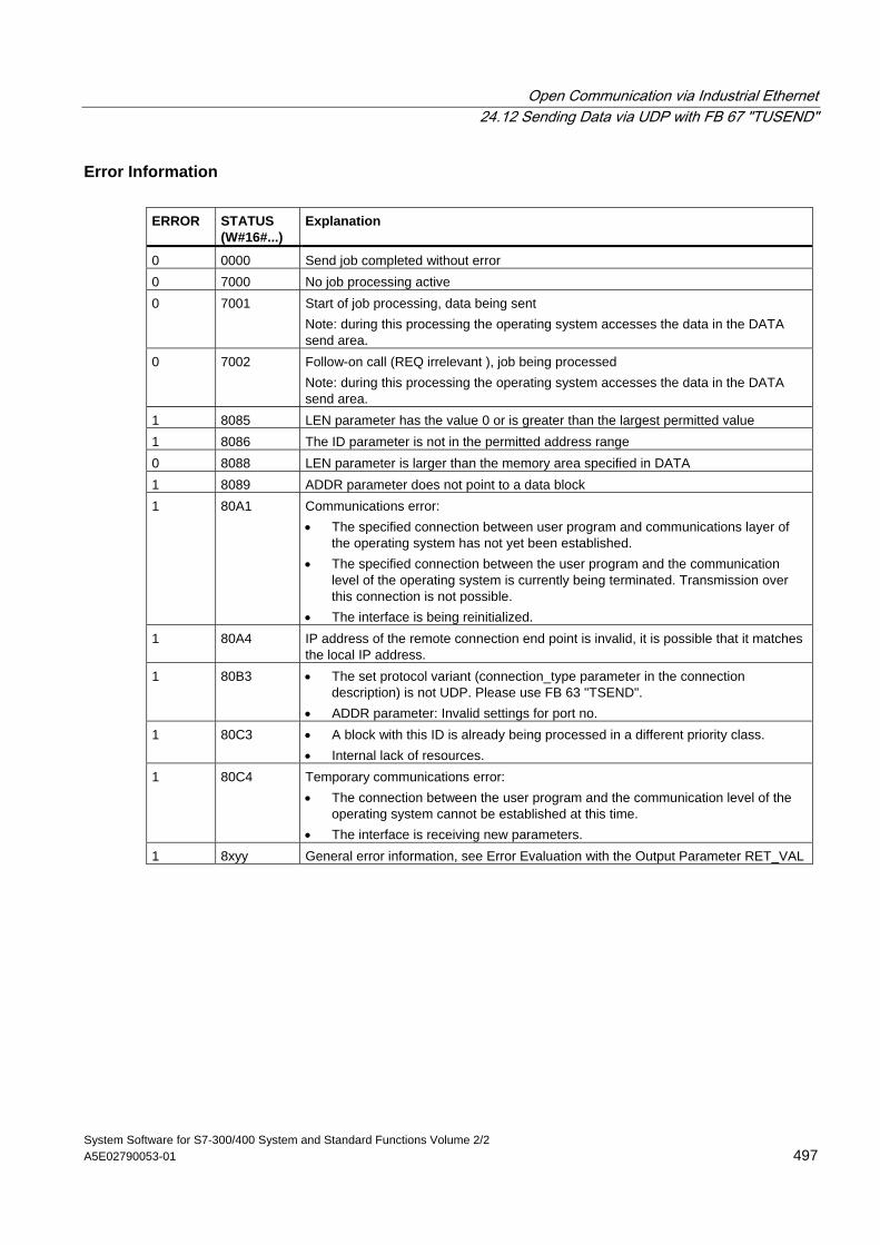
Open Communication via Industrial Ethernet 24.12 Sending Data via UDP with FB 67 "TUSEND"
System Software for S7-300/400 System and Standard Functions Volume 2/2 A5E02790053-01 497
Error Information ERROR STATUS
(W#16#...) Explanation
0 0000 Send job completed without error 0 7000 No job processing active 0 7001 Start of job processing, data being sent
Note: during this processing the operating system accesses the data in the DATA send area.
0 7002 Follow-on call (REQ irrelevant ), job being processed Note: during this processing the operating system accesses the data in the DATA send area.
1 8085 LEN parameter has the value 0 or is greater than the largest permitted value 1 8086 The ID parameter is not in the permitted address range 0 8088 LEN parameter is larger than the memory area specified in DATA 1 8089 ADDR parameter does not point to a data block 1 80A1 Communications error:
• The specified connection between user program and communications layer of the operating system has not yet been established.
• The specified connection between the user program and the communication level of the operating system is currently being terminated. Transmission over this connection is not possible.
• The interface is being reinitialized. 1 80A4 IP address of the remote connection end point is invalid, it is possible that it matches
the local IP address. 1 80B3 • The set protocol variant (connection_type parameter in the connection
description) is not UDP. Please use FB 63 "TSEND". • ADDR parameter: Invalid settings for port no.
1 80C3 • A block with this ID is already being processed in a different priority class. • Internal lack of resources.
1 80C4 Temporary communications error: • The connection between the user program and the communication level of the
operating system cannot be established at this time. • The interface is receiving new parameters.
1 8xyy General error information, see Error Evaluation with the Output Parameter RET_VAL
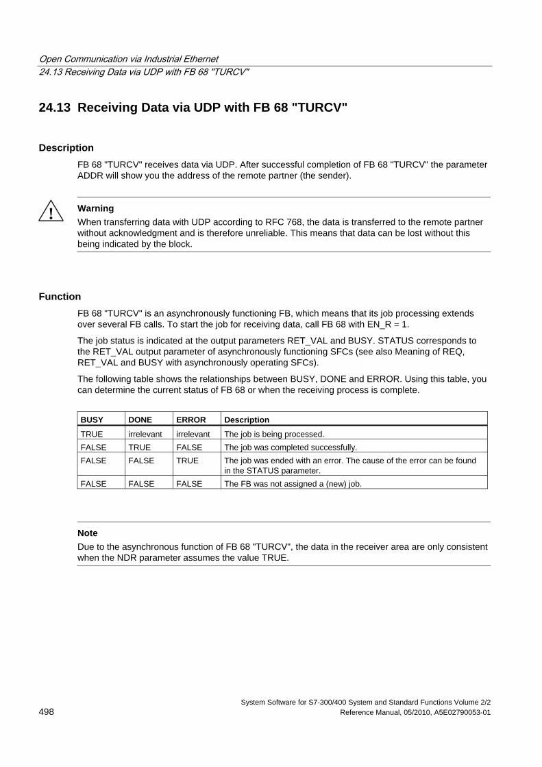
Open Communication via Industrial Ethernet 24.13 Receiving Data via UDP with FB 68 "TURCV"
System Software for S7-300/400 System and Standard Functions Volume 2/2 498 Reference Manual, 05/2010, A5E02790053-01
24.13 Receiving Data via UDP with FB 68 "TURCV"
Description FB 68 "TURCV" receives data via UDP. After successful completion of FB 68 "TURCV" the parameter ADDR will show you the address of the remote partner (the sender).
! Warning When transferring data with UDP according to RFC 768, the data is transferred to the remote partner without acknowledgment and is therefore unreliable. This means that data can be lost without this being indicated by the block.
Function FB 68 "TURCV" is an asynchronously functioning FB, which means that its job processing extends over several FB calls. To start the job for receiving data, call FB 68 with EN_R = 1.
The job status is indicated at the output parameters RET_VAL and BUSY. STATUS corresponds to the RET_VAL output parameter of asynchronously functioning SFCs (see also Meaning of REQ, RET_VAL and BUSY with asynchronously operating SFCs).
The following table shows the relationships between BUSY, DONE and ERROR. Using this table, you can determine the current status of FB 68 or when the receiving process is complete.
BUSY DONE ERROR Description
TRUE irrelevant irrelevant The job is being processed. FALSE TRUE FALSE The job was completed successfully. FALSE FALSE TRUE The job was ended with an error. The cause of the error can be found
in the STATUS parameter. FALSE FALSE FALSE The FB was not assigned a (new) job.
Note
Due to the asynchronous function of FB 68 "TURCV", the data in the receiver area are only consistent when the NDR parameter assumes the value TRUE.
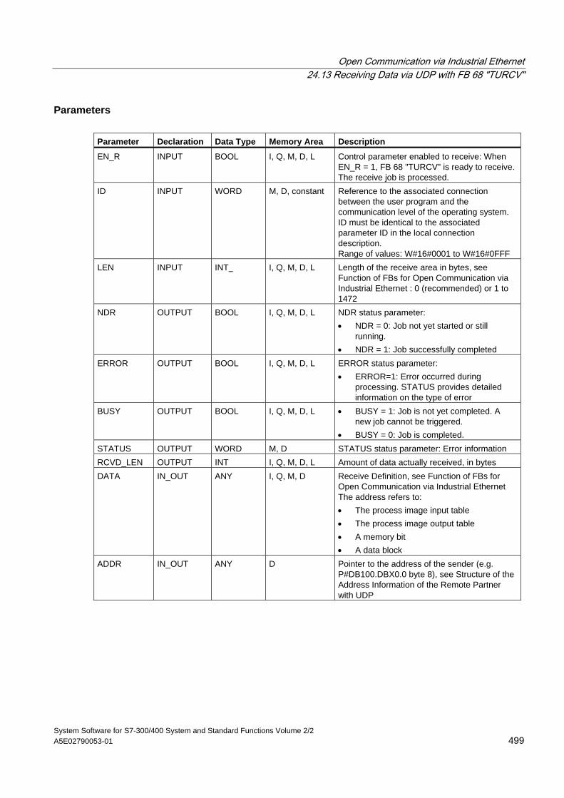
Open Communication via Industrial Ethernet 24.13 Receiving Data via UDP with FB 68 "TURCV"
System Software for S7-300/400 System and Standard Functions Volume 2/2 A5E02790053-01 499
Parameters Parameter Declaration Data Type Memory Area Description
EN_R INPUT BOOL I, Q, M, D, L Control parameter enabled to receive: When EN_R = 1, FB 68 "TURCV" is ready to receive. The receive job is processed.
ID INPUT WORD M, D, constant Reference to the associated connection between the user program and the communication level of the operating system. ID must be identical to the associated parameter ID in the local connection description. Range of values: W#16#0001 to W#16#0FFF
LEN INPUT INT I, Q, M, D, L Length of the receive area in bytes, see Function of FBs for Open Communication via Industrial Ethernet : 0 (recommended) or 1 to 1472
NDR OUTPUT BOOL I, Q, M, D, L NDR status parameter: • NDR = 0: Job not yet started or still
running. • NDR = 1: Job successfully completed
ERROR OUTPUT BOOL I, Q, M, D, L ERROR status parameter: • ERROR=1: Error occurred during
processing. STATUS provides detailed information on the type of error
BUSY OUTPUT BOOL I, Q, M, D, L • BUSY = 1: Job is not yet completed. A new job cannot be triggered.
• BUSY = 0: Job is completed. STATUS OUTPUT WORD M, D STATUS status parameter: Error information RCVD_LEN OUTPUT INT I, Q, M, D, L Amount of data actually received, in bytes DATA IN_OUT ANY I, Q, M, D Receive Definition, see Function of FBs for
Open Communication via Industrial Ethernet The address refers to: • The process image input table • The process image output table • A memory bit • A data block
ADDR IN_OUT ANY D Pointer to the address of the sender (e.g. P#DB100.DBX0.0 byte 8), see Structure of the Address Information of the Remote Partner with UDP
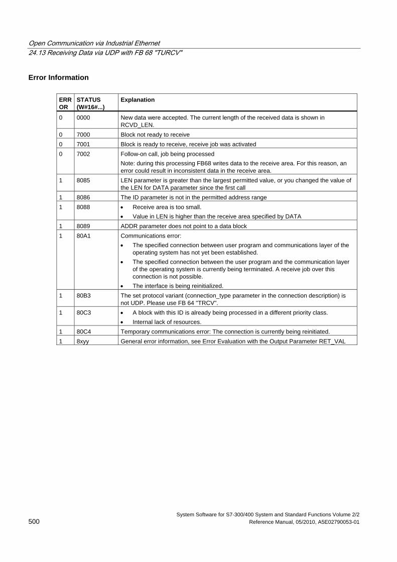
Open Communication via Industrial Ethernet 24.13 Receiving Data via UDP with FB 68 "TURCV"
System Software for S7-300/400 System and Standard Functions Volume 2/2 500 Reference Manual, 05/2010, A5E02790053-01
Error Information ERROR
STATUS (W#16#...)
Explanation
0 0000 New data were accepted. The current length of the received data is shown in RCVD_LEN.
0 7000 Block not ready to receive 0 7001 Block is ready to receive, receive job was activated 0 7002 Follow-on call, job being processed
Note: during this processing FB68 writes data to the receive area. For this reason, an error could result in inconsistent data in the receive area.
1 8085 LEN parameter is greater than the largest permitted value, or you changed the value of the LEN for DATA parameter since the first call
1 8086 The ID parameter is not in the permitted address range 1 8088 • Receive area is too small.
• Value in LEN is higher than the receive area specified by DATA 1 8089 ADDR parameter does not point to a data block 1 80A1 Communications error:
• The specified connection between user program and communications layer of the operating system has not yet been established.
• The specified connection between the user program and the communication layer of the operating system is currently being terminated. A receive job over this connection is not possible.
• The interface is being reinitialized. 1 80B3 The set protocol variant (connection_type parameter in the connection description) is
not UDP. Please use FB 64 "TRCV". 1 80C3 • A block with this ID is already being processed in a different priority class.
• Internal lack of resources. 1 80C4 Temporary communications error: The connection is currently being reinitiated. 1 8xyy General error information, see Error Evaluation with the Output Parameter RET_VAL
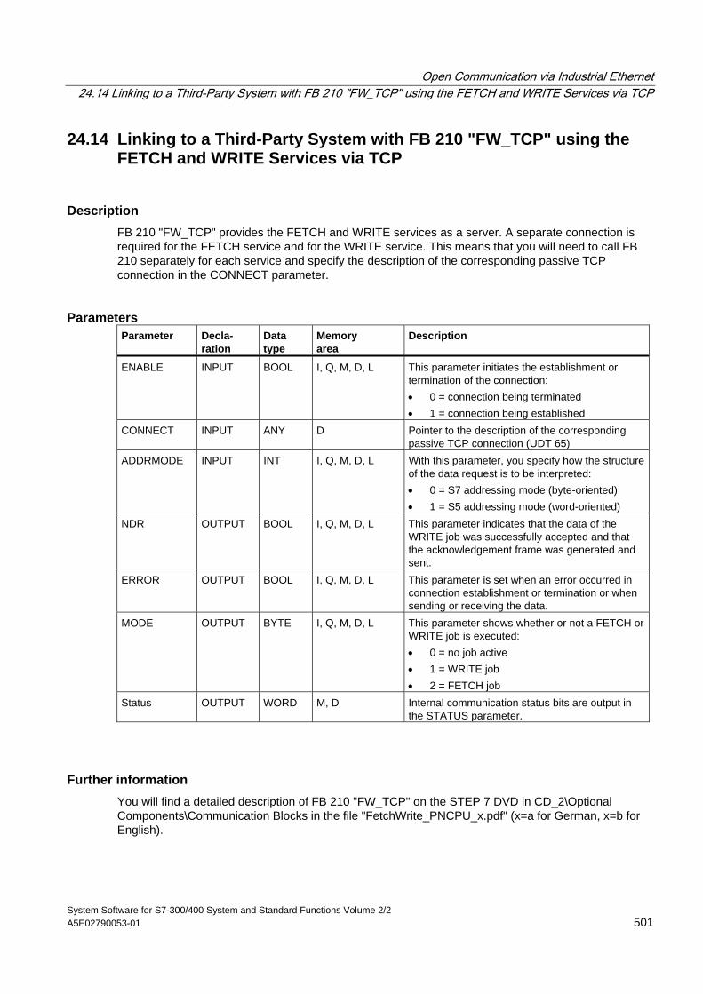
Open Communication via Industrial Ethernet 24.14 Linking to a Third-Party System with FB 210 "FW_TCP" using the FETCH and WRITE Services via TCP
System Software for S7-300/400 System and Standard Functions Volume 2/2 A5E02790053-01 501
24.14 Linking to a Third-Party System with FB 210 "FW_TCP" using the FETCH and WRITE Services via TCP
Description FB 210 "FW_TCP" provides the FETCH and WRITE services as a server. A separate connection is required for the FETCH service and for the WRITE service. This means that you will need to call FB 210 separately for each service and specify the description of the corresponding passive TCP connection in the CONNECT parameter.
Parameters Parameter Decla-
ration Data type
Memory area
Description
ENABLE INPUT BOOL I, Q, M, D, L This parameter initiates the establishment or termination of the connection: • 0 = connection being terminated • 1 = connection being established
CONNECT INPUT ANY D Pointer to the description of the corresponding passive TCP connection (UDT 65)
ADDRMODE INPUT INT I, Q, M, D, L With this parameter, you specify how the structure of the data request is to be interpreted: • 0 = S7 addressing mode (byte-oriented) • 1 = S5 addressing mode (word-oriented)
NDR OUTPUT BOOL I, Q, M, D, L This parameter indicates that the data of the WRITE job was successfully accepted and that the acknowledgement frame was generated and sent.
ERROR OUTPUT BOOL I, Q, M, D, L This parameter is set when an error occurred in connection establishment or termination or when sending or receiving the data.
MODE OUTPUT BYTE I, Q, M, D, L This parameter shows whether or not a FETCH or WRITE job is executed: • 0 = no job active • 1 = WRITE job • 2 = FETCH job
Status OUTPUT WORD M, D Internal communication status bits are output in the STATUS parameter.
Further information You will find a detailed description of FB 210 "FW_TCP" on the STEP 7 DVD in CD_2\Optional Components\Communication Blocks in the file "FetchWrite_PNCPU_x.pdf" (x=a for German, x=b for English).
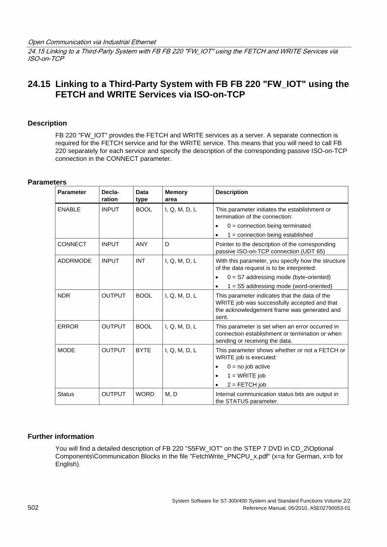
Open Communication via Industrial Ethernet 24.15 Linking to a Third-Party System with FB FB 220 "FW_IOT" using the FETCH and WRITE Services via ISO-on-TCP
System Software for S7-300/400 System and Standard Functions Volume 2/2 502 Reference Manual, 05/2010, A5E02790053-01
24.15 Linking to a Third-Party System with FB FB 220 "FW_IOT" using the FETCH and WRITE Services via ISO-on-TCP
Description FB 220 "FW_IOT" provides the FETCH and WRITE services as a server. A separate connection is required for the FETCH service and for the WRITE service. This means that you will need to call FB 220 separately for each service and specify the description of the corresponding passive ISO-on-TCP connection in the CONNECT parameter.
Parameters Parameter Decla-
ration Data type
Memory area
Description
ENABLE INPUT BOOL I, Q, M, D, L This parameter initiates the establishment or termination of the connection: • 0 = connection being terminated • 1 = connection being established
CONNECT INPUT ANY D Pointer to the description of the corresponding passive ISO-on-TCP connection (UDT 65)
ADDRMODE INPUT INT I, Q, M, D, L With this parameter, you specify how the structure of the data request is to be interpreted: • 0 = S7 addressing mode (byte-oriented) • 1 = S5 addressing mode (word-oriented)
NDR OUTPUT BOOL I, Q, M, D, L This parameter indicates that the data of the WRITE job was successfully accepted and that the acknowledgement frame was generated and sent.
ERROR OUTPUT BOOL I, Q, M, D, L This parameter is set when an error occurred in connection establishment or termination or when sending or receiving the data.
MODE OUTPUT BYTE I, Q, M, D, L This parameter shows whether or not a FETCH or WRITE job is executed: • 0 = no job active • 1 = WRITE job • 2 = FETCH job
Status OUTPUT WORD M, D Internal communication status bits are output in the STATUS parameter.
Further information You will find a detailed description of FB 220 "S5FW_IOT" on the STEP 7 DVD in CD_2\Optional Components\Communication Blocks in the file "FetchWrite_PNCPU_x.pdf" (x=a for German, x=b for English).
System Software for S7-300/400 System and Standard Functions Volume 2/2 Reference Manual, 05/2010, A5E02790053-01 503
25 Generating Block-Related Messages
25.1 Introduction to Generating Block-Related Messages with SFBs
SFBs for Generating Block-Related Messages You can generate a block-related message by calling one of the following SFBs in your program:
• SFB 36 "NOTIFY"
• SFB 31 "NOTIFY_8P"
• SFB 33 "ALARM"
• SFB 34 "ALARM_8"
• SFB 35 "ALARM_8P"
These SFBs have the following properties:
• Save with SFBs 36 "NOTIFY" and 31 "NOTIFY_8P", all detected 0 -> 1 or 1 -> 0 signal transitions when a block is called will result in a message transfer.
• When the default reporting procedure is set (acknowledgement triggered reporting disabled), the SFBs 33 "ALARM", 34 "ALARM_8" and 35 "ALARM_8P" will also generate a message when any signal transitions are detected when a block is called. If, on the other hand, you have enabled acknowledgement triggered reporting, not all signal transitions will trigger a message transfer (see below for details).
• Following execution of the block, the associated values (inputs SD_i) are read completely and assigned to the message (see "Send and Receive Parameters" in Common Parameters of SFBs/FBs and of the SFC/FC of S7 Communication.) In terms of consistency compared with high-priority classes, the following associated values are consistent:
Every associated value SD_i is inherently consistent.
With the status parameters DONE, ERROR and STATUS, you monitor the processing status of the block (see "Status Parameters" in Common Parameters of SFBs/FBs and of the SFC/FC of S7 Communication.)
Note
The parameters ID and EV_ID are only evaluated at the initial call of the block (the actual parameters or the defined values of the instance).
Generating Block-Related Messages 25.1 Introduction to Generating Block-Related Messages with SFBs
System Software for S7-300/400 System and Standard Functions Volume 2/2 504 Reference Manual, 05/2010, A5E02790053-01
Logging On Display Devices Before SFBs for generating block-related messages can send a message when a signal transition is detected, at least one display device (e.g. WinCC) must be logged on for block-related messages. Parameter STATUS = 1 if no login exists.
Signal transition detection One message memory with two memory blocks is available for each instance of a message block. This message memory is initially cleared. A signal transition at input SIG or at one of the inputs SIG_1, ... SIG_8 is entered in the first memory block. This memory block remains occupied until the corresponding message has been transferred. The next signal transition detected at input SIG or at one of the inputs SIG_1, ... SIG_8 is then entered in the second memory block. This second memory block will always be overwritten if the first block is still occupied. Output parameters ERROR and STATUS will indicate this loss of a message. This information is also passed to the online displaying devices with the next message that can be transferred. After the first memory block is cleared, the data of the second memory block are transferred to the first block. Thus, the second memory block is cleared again.
Acknowledgement triggered reporting You can reduce message traffic on your system by operating the SFBs 33 "ALARM", 34 "ALARM_8" And 35 "ALARM_8P" with acknowledgement triggered reporting.
That is, after an incoming message has been generated (Signal transition 0 > 1) initially for a signal, subsequent messages will not be generated until you have acknowledged the first message on a displaying device. The next message displayed on the display unit after your acknowledgement ids the outgoing message (Signal transition 1 to 0). The message cycle then restarts with an incoming message (Signal transition 0 to 1) which must be acknowledged. by this method you can use the display unit to control signal transition messages (save for the outgoing message).
Set the reporting method (enable or disable acknowledgement triggered reporting) for the SFBs 33 to 35 globally for the CPU in your STEP 7 configuration. Acknowledgement triggered reporting is disabled by default.
To ensure consistent message evaluation within your system, you should verify that all displaying devices can handle acknowledgement triggered reporting.
Note on operating displaying devices that can not handle acknowledgement triggered
reporting A CPU with enabled acknowledgement triggered reporting will distribute the messages only to displaying devices capable of handling this reporting method. The CPU will not send any messages if none of the displaying devices can handle acknowledgement triggered reporting. This situation is indicated once with ERROR=1 and STATUS=1.
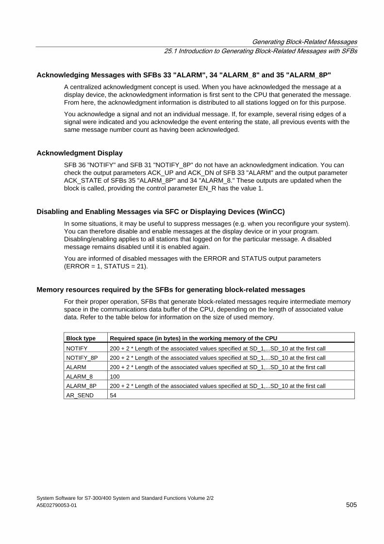
Generating Block-Related Messages 25.1 Introduction to Generating Block-Related Messages with SFBs
System Software for S7-300/400 System and Standard Functions Volume 2/2 A5E02790053-01 505
Acknowledging Messages with SFBs 33 "ALARM", 34 "ALARM_8" and 35 "ALARM_8P" A centralized acknowledgment concept is used. When you have acknowledged the message at a display device, the acknowledgment information is first sent to the CPU that generated the message. From here, the acknowledgment information is distributed to all stations logged on for this purpose.
You acknowledge a signal and not an individual message. If, for example, several rising edges of a signal were indicated and you acknowledge the event entering the state, all previous events with the same message number count as having been acknowledged.
Acknowledgment Display SFB 36 "NOTIFY" and SFB 31 "NOTIFY_8P" do not have an acknowledgment indication. You can check the output parameters ACK_UP and ACK_DN of SFB 33 "ALARM" and the output parameter ACK_STATE of SFBs 35 "ALARM_8P" and 34 "ALARM_8." These outputs are updated when the block is called, providing the control parameter EN_R has the value 1.
Disabling and Enabling Messages via SFC or Displaying Devices (WinCC) In some situations, it may be useful to suppress messages (e.g. when you reconfigure your system). You can therefore disable and enable messages at the display device or in your program. Disabling/enabling applies to all stations that logged on for the particular message. A disabled message remains disabled until it is enabled again.
You are informed of disabled messages with the ERROR and STATUS output parameters (ERROR = 1, STATUS = 21).
Memory resources required by the SFBs for generating block-related messages For their proper operation, SFBs that generate block-related messages require intermediate memory space in the communications data buffer of the CPU, depending on the length of associated value data. Refer to the table below for information on the size of used memory.
Block type Required space (in bytes) in the working memory of the CPU
NOTIFY 200 + 2 * Length of the associated values specified at SD_1,...SD_10 at the first call NOTIFY_8P 200 + 2 * Length of the associated values specified at SD_1,...SD_10 at the first call ALARM 200 + 2 * Length of the associated values specified at SD_1,...SD_10 at the first call ALARM_8 100 ALARM_8P 200 + 2 * Length of the associated values specified at SD_1,...SD_10 at the first call AR_SEND 54
Generating Block-Related Messages 25.1 Introduction to Generating Block-Related Messages with SFBs
System Software for S7-300/400 System and Standard Functions Volume 2/2 506 Reference Manual, 05/2010, A5E02790053-01
Amount of Transferable Data The data transferred with the associated values SD_i of the NOTIFY, NOTIFY_8P, ALARM and ALARM_8P SFBs must not exceed a maximum length. The maximum data length is calculated as follows:
maxleng = min (pdu_local, pdu_remote) - diff - 4 * number of SD_i parameters used
Where:
• min (pdu_lokal, pdu_remote) is the lowest value of the data fields pdu_lokal und pdu_remote
• pdu_local is the maximum length of the data fields of the local CPU (see the technical data of your CPU)
• pdu_remote is the maximum length of data fields of the display devices
• diff = 48, if acknowledgement triggered reporting is enabled, while diff = 44 if disabled.
Example:
A CPU 414-2 is sending messages across Industrial Ethernet to WinCC. Acknowledgement triggered reporting is disabled.
The associated values SD_1, SD_2 and SD_3 are used.
pdu_local = 480 bytes, pdu_remote = 480 bytes
Number of SD_i parameters used: 3
So that:
maxleng = min (480, 480) - 44 - 4 * 3 = 480 - 44 - 12 = 424
The maximum length of data that can be transferred per SFB is 424 bytes.
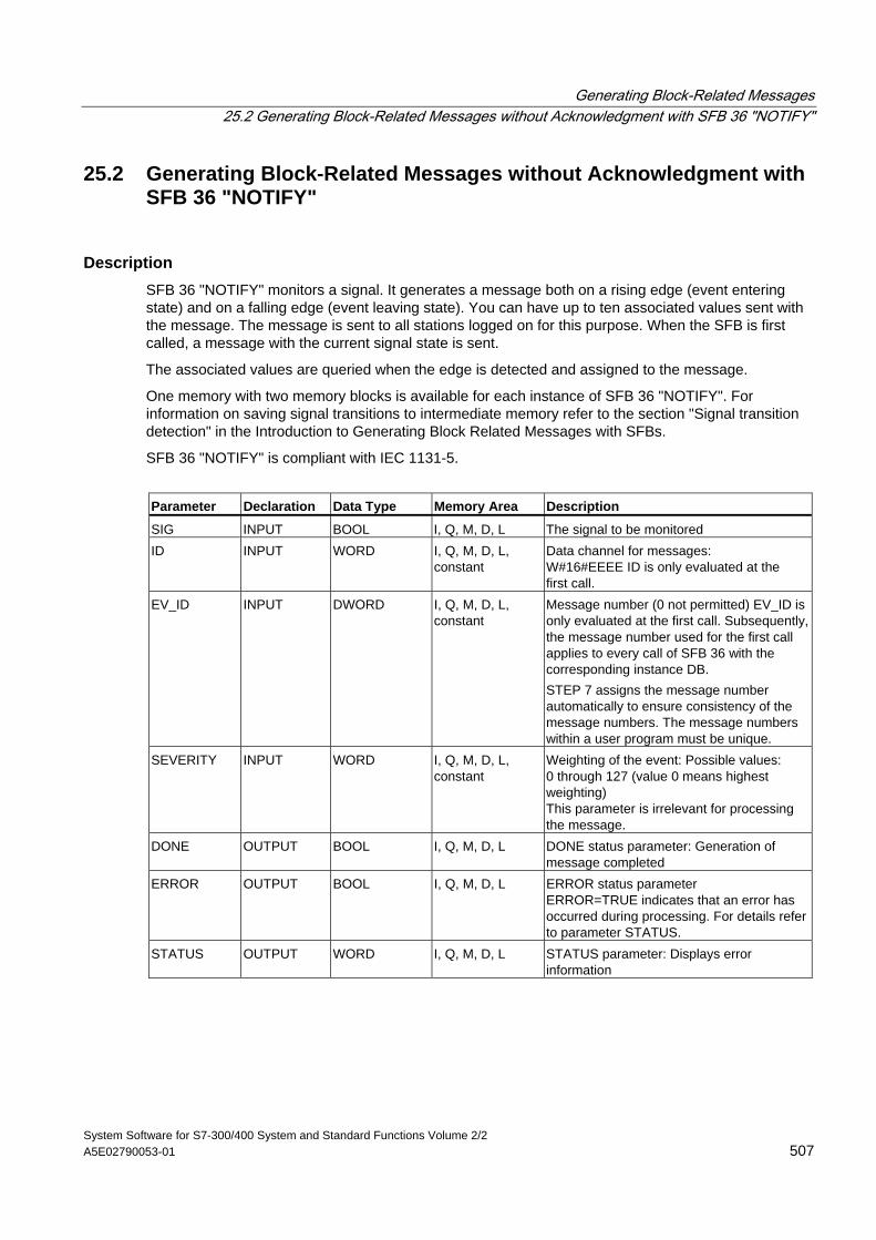
Generating Block-Related Messages 25.2 Generating Block-Related Messages without Acknowledgment with SFB 36 "NOTIFY"
System Software for S7-300/400 System and Standard Functions Volume 2/2 A5E02790053-01 507
25.2 Generating Block-Related Messages without Acknowledgment with SFB 36 "NOTIFY"
Description SFB 36 "NOTIFY" monitors a signal. It generates a message both on a rising edge (event entering state) and on a falling edge (event leaving state). You can have up to ten associated values sent with the message. The message is sent to all stations logged on for this purpose. When the SFB is first called, a message with the current signal state is sent.
The associated values are queried when the edge is detected and assigned to the message.
One memory with two memory blocks is available for each instance of SFB 36 "NOTIFY". For information on saving signal transitions to intermediate memory refer to the section "Signal transition detection" in the Introduction to Generating Block Related Messages with SFBs.
SFB 36 "NOTIFY" is compliant with IEC 1131-5.
Parameter Declaration Data Type Memory Area Description
SIG INPUT BOOL I, Q, M, D, L The signal to be monitored ID INPUT WORD I, Q, M, D, L,
constant Data channel for messages: W#16#EEEE ID is only evaluated at the first call.
EV_ID INPUT DWORD I, Q, M, D, L, constant
Message number (0 not permitted) EV_ID is only evaluated at the first call. Subsequently, the message number used for the first call applies to every call of SFB 36 with the corresponding instance DB. STEP 7 assigns the message number automatically to ensure consistency of the message numbers. The message numbers within a user program must be unique.
SEVERITY INPUT WORD I, Q, M, D, L, constant
Weighting of the event: Possible values: 0 through 127 (value 0 means highest weighting) This parameter is irrelevant for processing the message.
DONE OUTPUT BOOL I, Q, M, D, L DONE status parameter: Generation of message completed
ERROR OUTPUT BOOL I, Q, M, D, L ERROR status parameter ERROR=TRUE indicates that an error has occurred during processing. For details refer to parameter STATUS.
STATUS OUTPUT WORD I, Q, M, D, L STATUS parameter: Displays error information
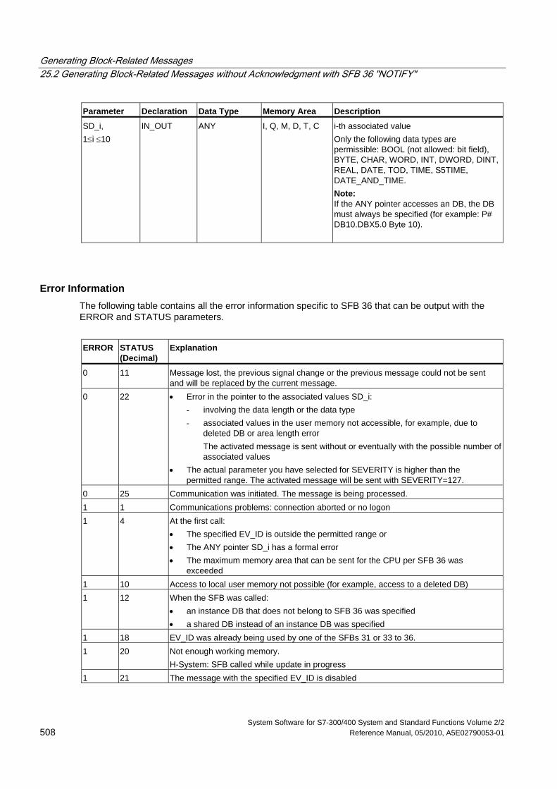
Generating Block-Related Messages 25.2 Generating Block-Related Messages without Acknowledgment with SFB 36 "NOTIFY"
System Software for S7-300/400 System and Standard Functions Volume 2/2 508 Reference Manual, 05/2010, A5E02790053-01
Parameter Declaration Data Type Memory Area Description
SD_i, 1≤i ≤10
IN_OUT ANY I, Q, M, D, T, C i-th associated value Only the following data types are permissible: BOOL (not allowed: bit field), BYTE, CHAR, WORD, INT, DWORD, DINT, REAL, DATE, TOD, TIME, S5TIME, DATE_AND_TIME. Note: If the ANY pointer accesses an DB, the DB must always be specified (for example: P# DB10.DBX5.0 Byte 10).
Error Information The following table contains all the error information specific to SFB 36 that can be output with the ERROR and STATUS parameters.
ERROR
STATUS (Decimal)
Explanation
0 11 Message lost, the previous signal change or the previous message could not be sent and will be replaced by the current message.
0 22 • Error in the pointer to the associated values SD_i: - involving the data length or the data type - associated values in the user memory not accessible, for example, due to
deleted DB or area length error The activated message is sent without or eventually with the possible number of
associated values • The actual parameter you have selected for SEVERITY is higher than the
permitted range. The activated message will be sent with SEVERITY=127. 0 25 Communication was initiated. The message is being processed. 1 1 Communications problems: connection aborted or no logon 1 4 At the first call:
• The specified EV_ID is outside the permitted range or • The ANY pointer SD_i has a formal error • The maximum memory area that can be sent for the CPU per SFB 36 was
exceeded 1 10 Access to local user memory not possible (for example, access to a deleted DB) 1 12 When the SFB was called:
• an instance DB that does not belong to SFB 36 was specified • a shared DB instead of an instance DB was specified
1 18 EV_ID was already being used by one of the SFBs 31 or 33 to 36. 1 20 Not enough working memory.
H-System: SFB called while update in progress 1 21 The message with the specified EV_ID is disabled
Generating Block-Related Messages 25.3 Generating Block Related Messages without Acknowledgement Display with SFB 31 "NOTIFY_8P"
System Software for S7-300/400 System and Standard Functions Volume 2/2 A5E02790053-01 509
25.3 Generating Block Related Messages without Acknowledgement Display with SFB 31 "NOTIFY_8P"
Description SFB 31 "NOTIFY_8P" represents an extension of SFB 36 "NOTIFY" to eight signals.
A message is generated if at least one signal transition has been detected. A message is always generated at the initial call of SFB 31. All eight signal are allocated a common message number that is split into eight sub-messages on the displaying device.
One memory with two memory blocks is available for each instance of SFB 31 "NOTIFY_8P". For information on saving signal transitions to intermediate memory refer to the section "Signal transition detection" in the Introduction to Generating Block Related Messages with SFBs.
Note
The displaying device shows the last two signal transitions, irrespective of message loss.
! Warning Before you call SFB 31 "NOTIFY_8P" in a CPU, you must insure that all connected displaying devices know this block. This is the case if at least one of the following release versions are conditional for the PLC: STEP 7 as V5.1 Service Pack 3, WinCC as of V5.1 Hot Fix 1, PCS7 as of V5.2 Service Pack 2, SIMATIC Device Driver as of V5.6. Otherwise, communication between the PLC and the connected displaying devices will be shut down. In this case you can no longer access your system with its connected displaying devices.
Generating Block-Related Messages 25.3 Generating Block Related Messages without Acknowledgement Display with SFB 31 "NOTIFY_8P"
System Software for S7-300/400 System and Standard Functions Volume 2/2 510 Reference Manual, 05/2010, A5E02790053-01
Parameter Declaration Data type Memory area Description
SIG_i, 1 ≤ i ≤ 8
INPUT BOOL I, Q, M, D, L. i-th signal to be monitored
ID INPUT WORD constant (I, Q, M, D, L) Data channel for messages: W#16#EEEE ID is evaluated only at the initial call.
EV_ID INPUT DWORD constant (I, Q, M, D, L) Message number (not permitted: 0) EV_ID is only evaluated at the first call. Subsequently, the message number used for the first call applies to every call of SFB 31 with the corresponding instance DB. STEP 7 assigns the message number automatically to ensure consistency of the message numbers. The message numbers within a user program must be unique.
SEVERITY INPUT WORD constant (I, Q, M, D, L) Weighting of the event Possible: 0 to 127 (value 0 = highest weighting); Default value: 64 This parameter is irrelevant for processing the message.
DONE OUTPUT BOOL I, Q, M, D, L Status parameter DONE: Message generation completed.
ERROR OUTPUT BOOL I, Q, M, D, L Status parameter ERROR ERROR=TRUE indicates that an error has occurred during processing. For details refer to parameter STATUS.
STATUS OUTPUT WORD I, Q, M, D, L Status parameter STATUS: Display of an error information
SD_i, 1 ≤ i ≤ 10
IN_OUT ANY I, Q, M, D, T, Z i-th associated value Permitted are only data of the type BOOL (not permitted: bit field), BYTE, CHAR, WORD, INT, DWORD, DINT, REAL, DATE, TOD, TIME, S5TIME, DATE_AND_TIME. Note: When the ANY pointer accesses a DB, the DB always must be specified. (e.g.: P# DB10.DBX5.0 Byte 10)
Generating Block-Related Messages 25.3 Generating Block Related Messages without Acknowledgement Display with SFB 31 "NOTIFY_8P"
System Software for S7-300/400 System and Standard Functions Volume 2/2 A5E02790053-01 511
Error information The table below contains all error information specific to SFB 31 and that can be output via the parameters ERROR and STATUS. ERROR STATUS (decimal) Explanation
0 11 Message lost: the previous signal change or the previous message could not be sent and will be replaced by the current message.
0 22 • Error in the pointer to the associated values SD_i: - Relating to data length / type - No access to associated values in user memory, e.g. because of a
deleted DB or area length error The activated message is transferred without or, is required, with
the maximum possible number of associated values. • Your selected actual parameter of SEVERITY is out of high limits. The
activated message will be sent with SEVERITY=127. 0 25 Communication was initiated. The message is being processed. 1 1 Communication errors: communication shut-down or no login 1 4 At the initial call
• the specified EV_ID was out of the permitted range • formal error in the ANY pointers SD_i • the maximum memory area length the CPU can transfer per SFB 31
has been exceeded 1 10 No access to local user memory (e.g. attempt to access a deleted DB) 1 12 At the call of the SFB
• an instance DB was specified that does not belong to SFB 31 • a global DB was specified instead of an instance DB
1 18 EV_ID was already in use by one of the SFBs 31 or 33 to 36. 1 20 Out of working memory.
H-System: Call of the SFB during an update 1 21 The message with the specified EV_ID is locked.
Generating Block-Related Messages 25.4 Generating Block-Related Messages with Acknowledgment with SFB 33 "ALARM"
System Software for S7-300/400 System and Standard Functions Volume 2/2 512 Reference Manual, 05/2010, A5E02790053-01
25.4 Generating Block-Related Messages with Acknowledgment with SFB 33 "ALARM"
Description SFB 33 "ALARM" monitors a signal.
Default mode (that is, acknowledgement triggered reporting is disabled): The block generates a message both on a positive edge (event entering state) and on a negative edge (event leaving state). You can have up to ten associated values sent with the message.
Acknowledgement triggered reporting is enabled: After an incoming message is generated for the signal, the block will no longer generate messages until you have acknowledged this incoming message on a displaying device.
(see also the introduction on Generating Block-Related Messages with SFBs.
The message is sent to all stations logged on for this purpose.
When the SFB is first called, a message with the current signal state is sent.
The ACK_UP output is reset at the rising edge. It is set when your acknowledgment of the event entering the state has arrived from a logged on display device.
The situation for the ACK_DN output is analogous: this is reset at the negative edge. It is set when your acknowledgment of the event leaving the state is received from a logged on display device. Once your acknowledgment has been received from a logged on display device, the acknowledgment information is passed on to all other stations logged on for this purpose.
One message memory with 2 memory blocks is available for each instance of SFB33 "ALARM". For information on saving signal transitions to intermediate memory refer to the section "Signal transition detection" in the Introduction to Generating Block-Related Messages with SFBs.
SFB 33 "ALARM" complies with the IEC 1131-5 standard.
Parameter Declaration Data Type Memory Area Description
EN_R INPUT BOOL I, Q, M, D, L, constant
Control parameter enabled to receive that decides whether the outputs ACK_UP and ACK_DN are updated at the first block call (EN_R=1) or not (EN_R=0). If EN_R=0 the output parameters ACK_UP and ACK_DN remain unchanged.
SIG INPUT BOOL I, Q, M, D, L The signal to be monitored ID INPUT WORD I, Q, M, D, L,
constant Data channel for messages: W#16#EEEE ID is only evaluated at the first call.
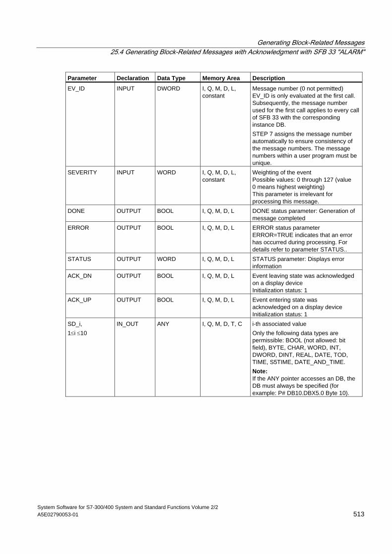
Generating Block-Related Messages 25.4 Generating Block-Related Messages with Acknowledgment with SFB 33 "ALARM"
System Software for S7-300/400 System and Standard Functions Volume 2/2 A5E02790053-01 513
Parameter Declaration Data Type Memory Area Description
EV_ID INPUT DWORD I, Q, M, D, L, constant
Message number (0 not permitted) EV_ID is only evaluated at the first call. Subsequently, the message number used for the first call applies to every call of SFB 33 with the corresponding instance DB. STEP 7 assigns the message number automatically to ensure consistency of the message numbers. The message numbers within a user program must be unique.
SEVERITY INPUT WORD I, Q, M, D, L, constant
Weighting of the event Possible values: 0 through 127 (value 0 means highest weighting) This parameter is irrelevant for processing this message.
DONE OUTPUT BOOL I, Q, M, D, L DONE status parameter: Generation of message completed
ERROR OUTPUT BOOL I, Q, M, D, L ERROR status parameter ERROR=TRUE indicates that an error has occurred during processing. For details refer to parameter STATUS..
STATUS OUTPUT WORD I, Q, M, D, L STATUS parameter: Displays error information
ACK_DN OUTPUT BOOL I, Q, M, D, L Event leaving state was acknowledged on a display device Initialization status: 1
ACK_UP OUTPUT BOOL I, Q, M, D, L Event entering state was acknowledged on a display device Initialization status: 1
SD_i, 1≤i ≤10
IN_OUT ANY I, Q, M, D, T, C i-th associated value Only the following data types are permissible: BOOL (not allowed: bit field), BYTE, CHAR, WORD, INT, DWORD, DINT, REAL, DATE, TOD, TIME, S5TIME, DATE_AND_TIME. Note: If the ANY pointer accesses an DB, the DB must always be specified (for example: P# DB10.DBX5.0 Byte 10).
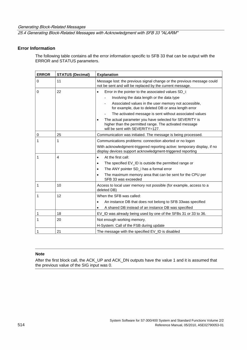
Generating Block-Related Messages 25.4 Generating Block-Related Messages with Acknowledgment with SFB 33 "ALARM"
System Software for S7-300/400 System and Standard Functions Volume 2/2 514 Reference Manual, 05/2010, A5E02790053-01
Error Information The following table contains all the error information specific to SFB 33 that can be output with the ERROR and STATUS parameters.
ERROR STATUS (Decimal) Explanation
0 11 Message lost: the previous signal change or the previous message could not be sent and will be replaced by the current message.
0 22 • Error in the pointer to the associated values SD_i: - Involving the data length or the data type - Associated values in the user memory not accessible,
for example, due to deleted DB or area length error - The activated message is sent without associated values
• The actual parameter you have selected for SEVERITY is higher than the permitted range. The activated message will be sent with SEVERITY=127.
0 25 Communication was initiated. The message is being processed. 1 1 Communications problems: connection aborted or no logon
With acknowledgment-triggered reporting active: temporary display, if no display devices support acknowledgment-triggered reporting
1 4 • At the first call: • The specified EV_ID is outside the permitted range or • The ANY pointer SD_i has a formal error • The maximum memory area that can be sent for the CPU per
SFB 33 was exceeded 1 10 Access to local user memory not possible (for example, access to a
deleted DB) 1 12 When the SFB was called:
• An instance DB that does not belong to SFB 33was specified • A shared DB instead of an instance DB was specified
1 18 EV_ID was already being used by one of the SFBs 31 or 33 to 36. 1 20 Not enough working memory.
H-System: Call of the FSB during update 1 21 The message with the specified EV_ID is disabled
Note
After the first block call, the ACK_UP and ACK_DN outputs have the value 1 and it is assumed that the previous value of the SIG input was 0.
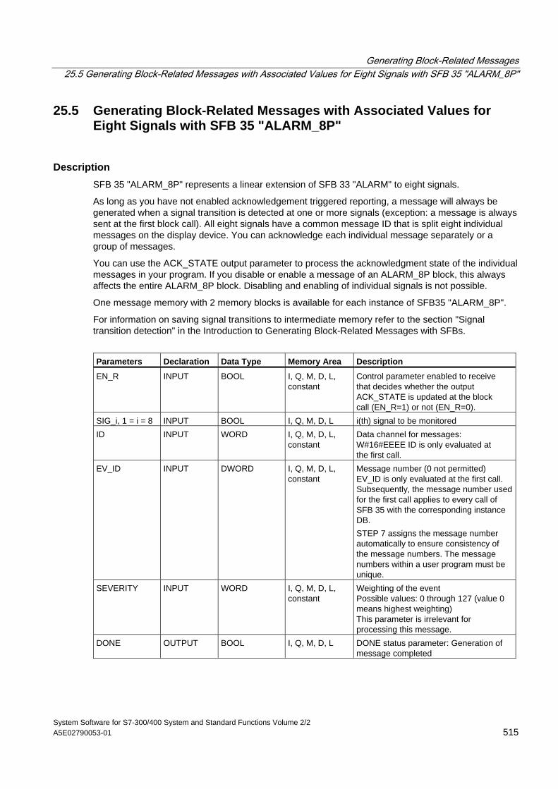
Generating Block-Related Messages 25.5 Generating Block-Related Messages with Associated Values for Eight Signals with SFB 35 "ALARM_8P"
System Software for S7-300/400 System and Standard Functions Volume 2/2 A5E02790053-01 515
25.5 Generating Block-Related Messages with Associated Values for Eight Signals with SFB 35 "ALARM_8P"
Description SFB 35 "ALARM_8P" represents a linear extension of SFB 33 "ALARM" to eight signals.
As long as you have not enabled acknowledgement triggered reporting, a message will always be generated when a signal transition is detected at one or more signals (exception: a message is always sent at the first block call). All eight signals have a common message ID that is split eight individual messages on the display device. You can acknowledge each individual message separately or a group of messages.
You can use the ACK_STATE output parameter to process the acknowledgment state of the individual messages in your program. If you disable or enable a message of an ALARM_8P block, this always affects the entire ALARM_8P block. Disabling and enabling of individual signals is not possible.
One message memory with 2 memory blocks is available for each instance of SFB35 "ALARM_8P".
For information on saving signal transitions to intermediate memory refer to the section "Signal transition detection" in the Introduction to Generating Block-Related Messages with SFBs.
Parameters Declaration Data Type Memory Area Description
EN_R INPUT BOOL I, Q, M, D, L, constant
Control parameter enabled to receive that decides whether the output ACK_STATE is updated at the block call (EN_R=1) or not (EN_R=0).
SIG_i, 1 = i = 8 INPUT BOOL I, Q, M, D, L i(th) signal to be monitored ID INPUT WORD I, Q, M, D, L,
constant Data channel for messages: W#16#EEEE ID is only evaluated at the first call.
EV_ID INPUT DWORD I, Q, M, D, L, constant
Message number (0 not permitted) EV_ID is only evaluated at the first call. Subsequently, the message number used for the first call applies to every call of SFB 35 with the corresponding instance DB. STEP 7 assigns the message number automatically to ensure consistency of the message numbers. The message numbers within a user program must be unique.
SEVERITY INPUT WORD I, Q, M, D, L, constant
Weighting of the event Possible values: 0 through 127 (value 0 means highest weighting) This parameter is irrelevant for processing this message.
DONE OUTPUT BOOL I, Q, M, D, L DONE status parameter: Generation of message completed
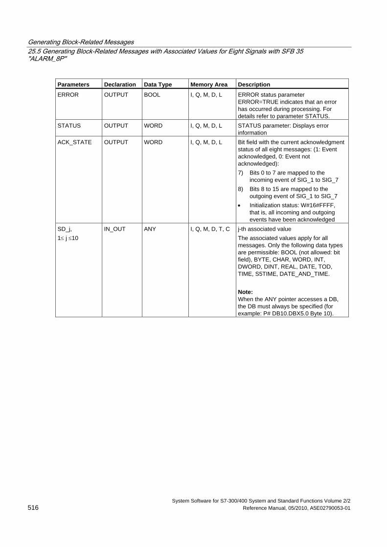
Generating Block-Related Messages 25.5 Generating Block-Related Messages with Associated Values for Eight Signals with SFB 35 "ALARM_8P"
System Software for S7-300/400 System and Standard Functions Volume 2/2 516 Reference Manual, 05/2010, A5E02790053-01
Parameters Declaration Data Type Memory Area Description
ERROR OUTPUT BOOL I, Q, M, D, L ERROR status parameter ERROR=TRUE indicates that an error has occurred during processing. For details refer to parameter STATUS.
STATUS OUTPUT WORD I, Q, M, D, L STATUS parameter: Displays error information
ACK_STATE OUTPUT WORD I, Q, M, D, L Bit field with the current acknowledgment status of all eight messages: (1: Event acknowledged, 0: Event not acknowledged): 7) Bits 0 to 7 are mapped to the
incoming event of SIG_1 to SIG_7 8) Bits 8 to 15 are mapped to the
outgoing event of SIG_1 to SIG_7 • Initialization status: W#16#FFFF,
that is, all incoming and outgoing events have been acknowledged
SD_j, 1≤ j ≤10
IN_OUT ANY I, Q, M, D, T, C j-th associated value The associated values apply for all messages. Only the following data types are permissible: BOOL (not allowed: bit field), BYTE, CHAR, WORD, INT, DWORD, DINT, REAL, DATE, TOD, TIME, S5TIME, DATE_AND_TIME. Note: When the ANY pointer accesses a DB, the DB must always be specified (for example: P# DB10.DBX5.0 Byte 10).
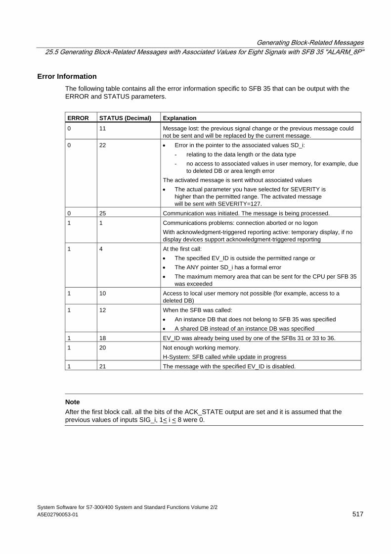
Generating Block-Related Messages 25.5 Generating Block-Related Messages with Associated Values for Eight Signals with SFB 35 "ALARM_8P"
System Software for S7-300/400 System and Standard Functions Volume 2/2 A5E02790053-01 517
Error Information The following table contains all the error information specific to SFB 35 that can be output with the ERROR and STATUS parameters.
ERROR STATUS (Decimal) Explanation
0 11 Message lost: the previous signal change or the previous message could not be sent and will be replaced by the current message.
0 22 • Error in the pointer to the associated values SD_i: - relating to the data length or the data type - no access to associated values in user memory, for example, due
to deleted DB or area length error The activated message is sent without associated values • The actual parameter you have selected for SEVERITY is
higher than the permitted range. The activated message will be sent with SEVERITY=127.
0 25 Communication was initiated. The message is being processed. 1 1 Communications problems: connection aborted or no logon
With acknowledgment-triggered reporting active: temporary display, if no display devices support acknowledgment-triggered reporting
1 4 At the first call: • The specified EV_ID is outside the permitted range or • The ANY pointer SD_i has a formal error • The maximum memory area that can be sent for the CPU per SFB 35
was exceeded 1 10 Access to local user memory not possible (for example, access to a
deleted DB) 1 12 When the SFB was called:
• An instance DB that does not belong to SFB 35 was specified • A shared DB instead of an instance DB was specified
1 18 EV_ID was already being used by one of the SFBs 31 or 33 to 36. 1 20 Not enough working memory.
H-System: SFB called while update in progress 1 21 The message with the specified EV_ID is disabled.
Note
After the first block call. all the bits of the ACK_STATE output are set and it is assumed that the previous values of inputs SIG_i, 1< i < 8 were 0.
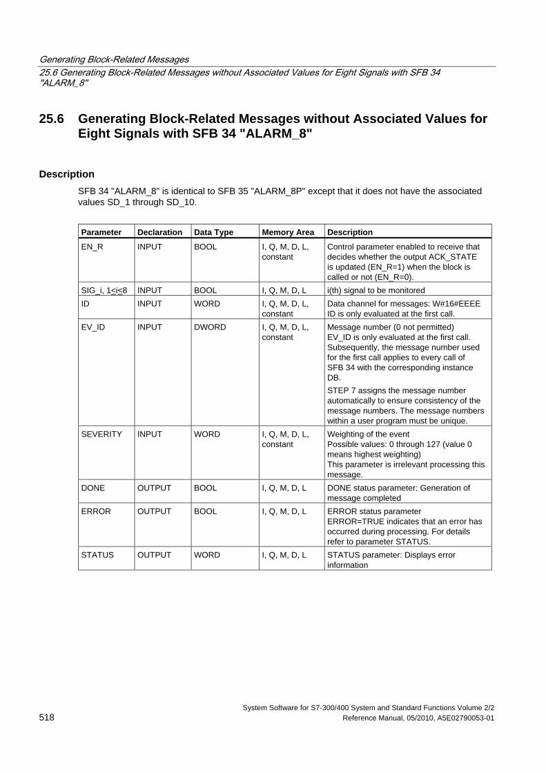
Generating Block-Related Messages 25.6 Generating Block-Related Messages without Associated Values for Eight Signals with SFB 34 "ALARM_8"
System Software for S7-300/400 System and Standard Functions Volume 2/2 518 Reference Manual, 05/2010, A5E02790053-01
25.6 Generating Block-Related Messages without Associated Values for Eight Signals with SFB 34 "ALARM_8"
Description SFB 34 "ALARM_8" is identical to SFB 35 "ALARM_8P" except that it does not have the associated values SD_1 through SD_10.
Parameter Declaration Data Type Memory Area Description
EN_R INPUT BOOL I, Q, M, D, L, constant
Control parameter enabled to receive that decides whether the output ACK_STATE is updated (EN_R=1) when the block is called or not (EN_R=0).
SIG_i, 1<i<8 INPUT BOOL I, Q, M, D, L i(th) signal to be monitored ID INPUT WORD I, Q, M, D, L,
constant Data channel for messages: W#16#EEEE ID is only evaluated at the first call.
EV_ID INPUT DWORD I, Q, M, D, L, constant
Message number (0 not permitted) EV_ID is only evaluated at the first call. Subsequently, the message number used for the first call applies to every call of SFB 34 with the corresponding instance DB. STEP 7 assigns the message number automatically to ensure consistency of the message numbers. The message numbers within a user program must be unique.
SEVERITY INPUT WORD I, Q, M, D, L, constant
Weighting of the event Possible values: 0 through 127 (value 0 means highest weighting) This parameter is irrelevant processing this message.
DONE OUTPUT BOOL I, Q, M, D, L DONE status parameter: Generation of message completed
ERROR OUTPUT BOOL I, Q, M, D, L ERROR status parameter ERROR=TRUE indicates that an error has occurred during processing. For details refer to parameter STATUS.
STATUS OUTPUT WORD I, Q, M, D, L STATUS parameter: Displays error information
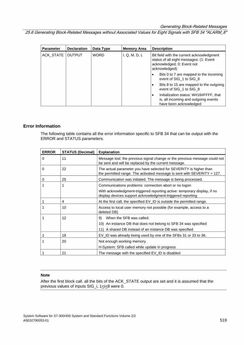
Generating Block-Related Messages 25.6 Generating Block-Related Messages without Associated Values for Eight Signals with SFB 34 "ALARM_8"
System Software for S7-300/400 System and Standard Functions Volume 2/2 A5E02790053-01 519
Parameter Declaration Data Type Memory Area Description
ACK_STATE OUTPUT WORD I, Q, M, D, L Bit field with the current acknowledgment status of all eight messages: (1: Event acknowledged, 0: Event not acknowledged): • Bits 0 to 7 are mapped to the incoming
event of SIG_1 to SIG_8 • Bits 8 to 15 are mapped to the outgoing
event of SIG_1 to SIG_8 • Initialization status: W#16#FFFF, that
is, all incoming and outgoing events have been acknowledged
Error Information The following table contains all the error information specific to SFB 34 that can be output with the ERROR and STATUS parameters.
ERROR STATUS (Decimal) Explanation
0 11 Message lost: the previous signal change or the previous message could not be sent and will be replaced by the current message.
0 22 The actual parameter you have selected for SEVERITY is higher than the permitted range. The activated message is sent with SEVERITY = 127.
0 25 Communication was initiated. The message is being processed. 1 1 Communications problems: connection abort or no logon
With acknowledgment-triggered reporting active: temporary display, if no display devices support acknowledgment-triggered reporting
1 4 At the first call, the specified EV_ID is outside the permitted range. 1 10 Access to local user memory not possible (for example, access to a
deleted DB) 1 12 9) When the SFB was called:
10) An instance DB that does not belong to SFB 34 was specified 11) A shared DB instead of an instance DB was specified
1 18 EV_ID was already being used by one of the SFBs 31 or 33 to 36. 1 20 Not enough working memory.
H-System: SFB called while update in progress 1 21 The message with the specified EV_ID is disabled
Note
After the first block call. all the bits of the ACK_STATE output are set and it is assumed that the previous values of inputs SIG_i, 1<i<8 were 0.
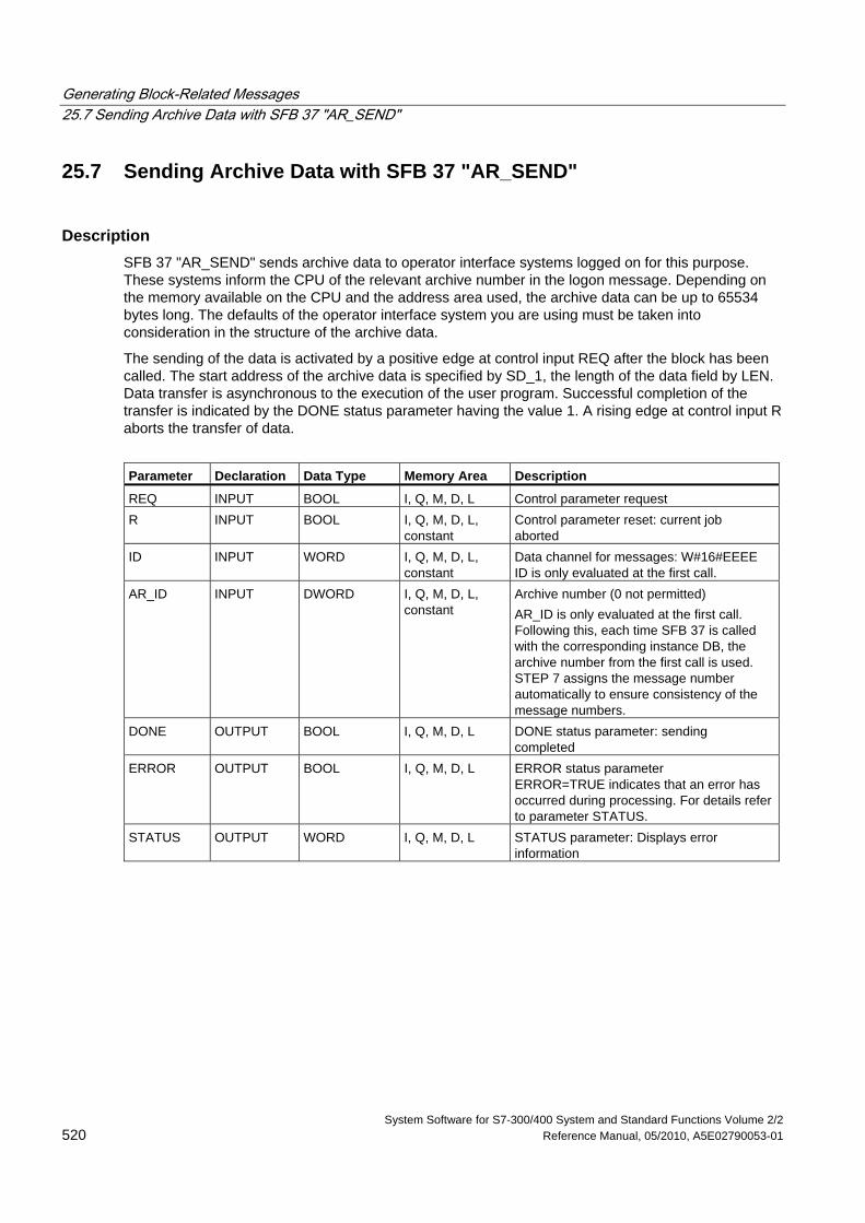
Generating Block-Related Messages 25.7 Sending Archive Data with SFB 37 "AR_SEND"
System Software for S7-300/400 System and Standard Functions Volume 2/2 520 Reference Manual, 05/2010, A5E02790053-01
25.7 Sending Archive Data with SFB 37 "AR_SEND"
Description SFB 37 "AR_SEND" sends archive data to operator interface systems logged on for this purpose. These systems inform the CPU of the relevant archive number in the logon message. Depending on the memory available on the CPU and the address area used, the archive data can be up to 65534 bytes long. The defaults of the operator interface system you are using must be taken into consideration in the structure of the archive data.
The sending of the data is activated by a positive edge at control input REQ after the block has been called. The start address of the archive data is specified by SD_1, the length of the data field by LEN. Data transfer is asynchronous to the execution of the user program. Successful completion of the transfer is indicated by the DONE status parameter having the value 1. A rising edge at control input R aborts the transfer of data.
Parameter Declaration Data Type Memory Area Description
REQ INPUT BOOL I, Q, M, D, L Control parameter request R INPUT BOOL I, Q, M, D, L,
constant Control parameter reset: current job aborted
ID INPUT WORD I, Q, M, D, L, constant
Data channel for messages: W#16#EEEE ID is only evaluated at the first call.
AR_ID INPUT DWORD I, Q, M, D, L, constant
Archive number (0 not permitted) AR_ID is only evaluated at the first call. Following this, each time SFB 37 is called with the corresponding instance DB, the archive number from the first call is used. STEP 7 assigns the message number automatically to ensure consistency of the message numbers.
DONE OUTPUT BOOL I, Q, M, D, L DONE status parameter: sending completed
ERROR OUTPUT BOOL I, Q, M, D, L ERROR status parameter ERROR=TRUE indicates that an error has occurred during processing. For details refer to parameter STATUS.
STATUS OUTPUT WORD I, Q, M, D, L STATUS parameter: Displays error information
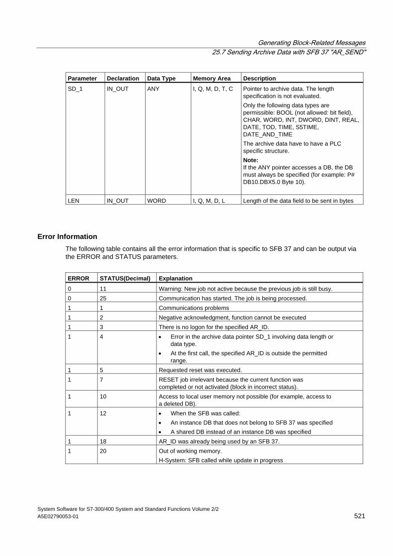
Generating Block-Related Messages 25.7 Sending Archive Data with SFB 37 "AR_SEND"
System Software for S7-300/400 System and Standard Functions Volume 2/2 A5E02790053-01 521
Parameter Declaration Data Type Memory Area Description
SD_1 IN_OUT ANY I, Q, M, D, T, C Pointer to archive data. The length specification is not evaluated. Only the following data types are permissible: BOOL (not allowed: bit field), CHAR, WORD, INT, DWORD, DINT, REAL, DATE, TOD, TIME, S5TIME, DATE_AND_TIME The archive data have to have a PLC specific structure. Note: If the ANY pointer accesses a DB, the DB must always be specified (for example: P# DB10.DBX5.0 Byte 10).
LEN IN_OUT WORD I, Q, M, D, L Length of the data field to be sent in bytes
Error Information The following table contains all the error information that is specific to SFB 37 and can be output via the ERROR and STATUS parameters.
ERROR STATUS(Decimal) Explanation
0 11 Warning: New job not active because the previous job is still busy. 0 25 Communication has started. The job is being processed. 1 1 Communications problems 1 2 Negative acknowledgment, function cannot be executed 1 3 There is no logon for the specified AR_ID. 1 4 • Error in the archive data pointer SD_1 involving data length or
data type. • At the first call, the specified AR_ID is outside the permitted
range. 1 5 Requested reset was executed. 1 7 RESET job irrelevant because the current function was
completed or not activated (block in incorrect status). 1 10 Access to local user memory not possible (for example, access to
a deleted DB). 1 12 • When the SFB was called:
• An instance DB that does not belong to SFB 37 was specified • A shared DB instead of an instance DB was specified
1 18 AR_ID was already being used by an SFB 37. 1 20 Out of working memory.
H-System: SFB called while update in progress
Generating Block-Related Messages 25.7 Sending Archive Data with SFB 37 "AR_SEND"
System Software for S7-300/400 System and Standard Functions Volume 2/2 522 Reference Manual, 05/2010, A5E02790053-01
Data Consistency To ensure data consistency, you may only write to the part of the currently used sending area only after the current sending process is completed. This is the case when the status parameters DONE assumes the value 1.
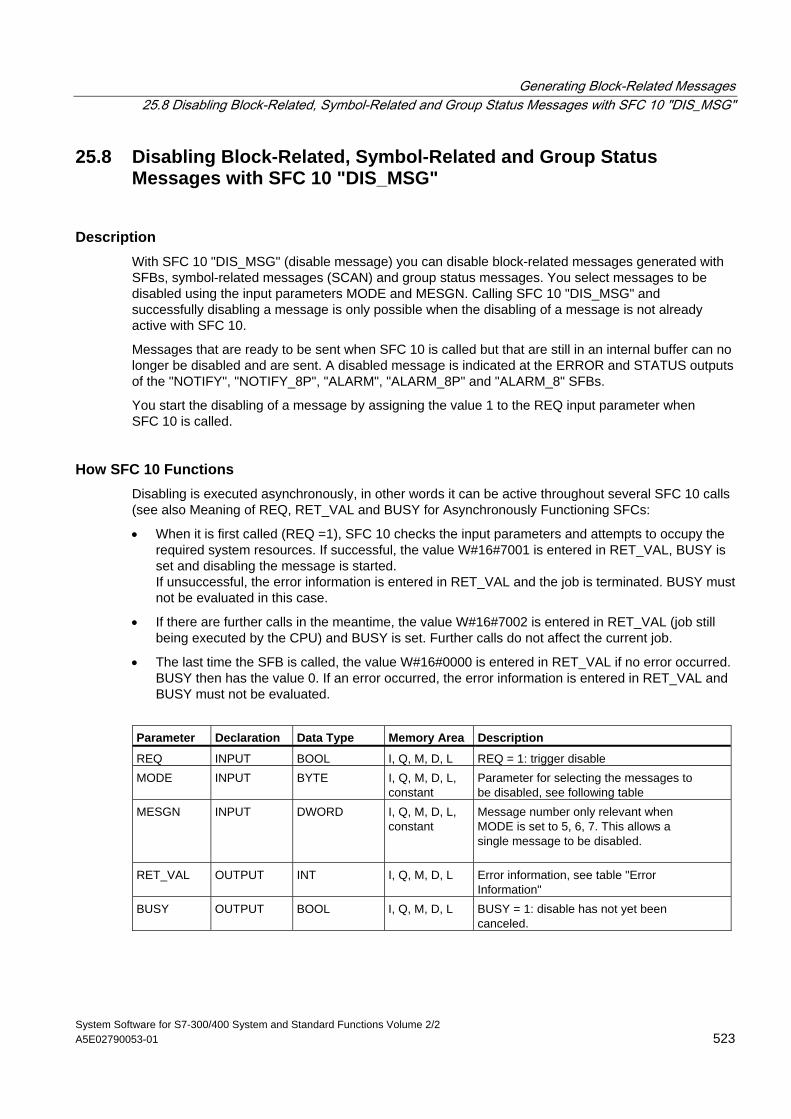
Generating Block-Related Messages 25.8 Disabling Block-Related, Symbol-Related and Group Status Messages with SFC 10 "DIS_MSG"
System Software for S7-300/400 System and Standard Functions Volume 2/2 A5E02790053-01 523
25.8 Disabling Block-Related, Symbol-Related and Group Status Messages with SFC 10 "DIS_MSG"
Description With SFC 10 "DIS_MSG" (disable message) you can disable block-related messages generated with SFBs, symbol-related messages (SCAN) and group status messages. You select messages to be disabled using the input parameters MODE and MESGN. Calling SFC 10 "DIS_MSG" and successfully disabling a message is only possible when the disabling of a message is not already active with SFC 10.
Messages that are ready to be sent when SFC 10 is called but that are still in an internal buffer can no longer be disabled and are sent. A disabled message is indicated at the ERROR and STATUS outputs of the "NOTIFY", "NOTIFY_8P", "ALARM", "ALARM_8P" and "ALARM_8" SFBs.
You start the disabling of a message by assigning the value 1 to the REQ input parameter when SFC 10 is called.
How SFC 10 Functions Disabling is executed asynchronously, in other words it can be active throughout several SFC 10 calls (see also Meaning of REQ, RET_VAL and BUSY for Asynchronously Functioning SFCs:
• When it is first called (REQ =1), SFC 10 checks the input parameters and attempts to occupy the required system resources. If successful, the value W#16#7001 is entered in RET_VAL, BUSY is set and disabling the message is started. If unsuccessful, the error information is entered in RET_VAL and the job is terminated. BUSY must not be evaluated in this case.
• If there are further calls in the meantime, the value W#16#7002 is entered in RET_VAL (job still being executed by the CPU) and BUSY is set. Further calls do not affect the current job.
• The last time the SFB is called, the value W#16#0000 is entered in RET_VAL if no error occurred. BUSY then has the value 0. If an error occurred, the error information is entered in RET_VAL and BUSY must not be evaluated.
Parameter Declaration Data Type Memory Area Description
REQ INPUT BOOL I, Q, M, D, L REQ = 1: trigger disable MODE INPUT BYTE I, Q, M, D, L,
constant Parameter for selecting the messages to be disabled, see following table
MESGN INPUT DWORD I, Q, M, D, L, constant
Message number only relevant when MODE is set to 5, 6, 7. This allows a single message to be disabled.
RET_VAL OUTPUT INT I, Q, M, D, L Error information, see table "Error Information"
BUSY OUTPUT BOOL I, Q, M, D, L BUSY = 1: disable has not yet been canceled.
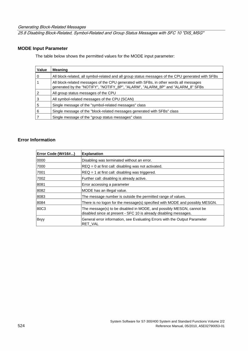
Generating Block-Related Messages 25.8 Disabling Block-Related, Symbol-Related and Group Status Messages with SFC 10 "DIS_MSG"
System Software for S7-300/400 System and Standard Functions Volume 2/2 524 Reference Manual, 05/2010, A5E02790053-01
MODE Input Parameter The table below shows the permitted values for the MODE input parameter:
Value Meaning
0 All block-related, all symbol-related and all group status messages of the CPU generated with SFBs 1 All block-related messages of the CPU generated with SFBs, in other words all messages
generated by the "NOTIFY", "NOTIFY_8P", "ALARM", "ALARM_8P" and "ALARM_8" SFBs 2 All group status messages of the CPU 3 All symbol-related messages of the CPU (SCAN) 5 Single message of the "symbol-related messages" class 6 Single message of the "block-related messages generated with SFBs" class 7 Single message of the "group status messages" class
Error Information Error Code (W#16#...) Explanation
0000 Disabling was terminated without an error. 7000 REQ = 0 at first call: disabling was not activated. 7001 REQ = 1 at first call: disabling was triggered. 7002 Further call: disabling is already active. 8081 Error accessing a parameter 8082 MODE has an illegal value. 8083 The message number is outside the permitted range of values. 8084 There is no logon for the message(s) specified with MODE and possibly MESGN. 80C3 The message(s) to be disabled in MODE, and possibly MESGN, cannot be
disabled since at present - SFC 10 is already disabling messages. 8xyy General error information, see Evaluating Errors with the Output Parameter
RET_VAL
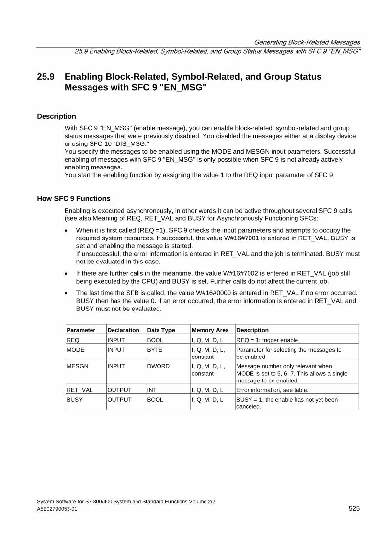
Generating Block-Related Messages 25.9 Enabling Block-Related, Symbol-Related, and Group Status Messages with SFC 9 "EN_MSG"
System Software for S7-300/400 System and Standard Functions Volume 2/2 A5E02790053-01 525
25.9 Enabling Block-Related, Symbol-Related, and Group Status Messages with SFC 9 "EN_MSG"
Description With SFC 9 "EN_MSG" (enable message), you can enable block-related, symbol-related and group status messages that were previously disabled. You disabled the messages either at a display device or using SFC 10 "DIS_MSG." You specify the messages to be enabled using the MODE and MESGN input parameters. Successful enabling of messages with SFC 9 "EN_MSG" is only possible when SFC 9 is not already actively enabling messages. You start the enabling function by assigning the value 1 to the REQ input parameter of SFC 9.
How SFC 9 Functions Enabling is executed asynchronously, in other words it can be active throughout several SFC 9 calls (see also Meaning of REQ, RET_VAL and BUSY for Asynchronously Functioning SFCs:
• When it is first called (REQ =1), SFC 9 checks the input parameters and attempts to occupy the required system resources. If successful, the value W#16#7001 is entered in RET_VAL, BUSY is set and enabling the message is started. If unsuccessful, the error information is entered in RET_VAL and the job is terminated. BUSY must not be evaluated in this case.
• If there are further calls in the meantime, the value W#16#7002 is entered in RET_VAL (job still being executed by the CPU) and BUSY is set. Further calls do not affect the current job.
• The last time the SFB is called, the value W#16#0000 is entered in RET_VAL if no error occurred. BUSY then has the value 0. If an error occurred, the error information is entered in RET_VAL and BUSY must not be evaluated.
Parameter Declaration Data Type Memory Area Description
REQ INPUT BOOL I, Q, M, D, L REQ = 1: trigger enable MODE INPUT BYTE I, Q, M, D, L,
constant Parameter for selecting the messages to be enabled
MESGN INPUT DWORD I, Q, M, D, L, constant
Message number only relevant when MODE is set to 5, 6, 7. This allows a single message to be enabled.
RET_VAL OUTPUT INT I, Q, M, D, L Error information, see table. BUSY OUTPUT BOOL I, Q, M, D, L BUSY = 1: the enable has not yet been
canceled.
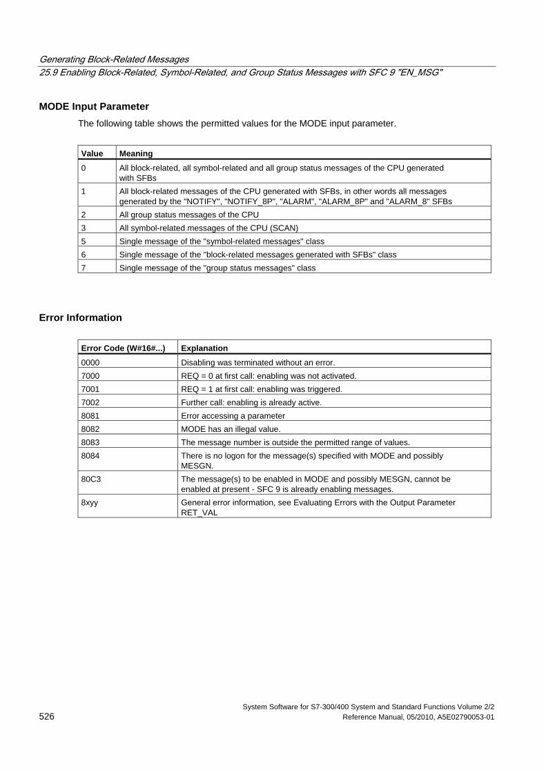
Generating Block-Related Messages 25.9 Enabling Block-Related, Symbol-Related, and Group Status Messages with SFC 9 "EN_MSG"
System Software for S7-300/400 System and Standard Functions Volume 2/2 526 Reference Manual, 05/2010, A5E02790053-01
MODE Input Parameter The following table shows the permitted values for the MODE input parameter.
Value Meaning
0 All block-related, all symbol-related and all group status messages of the CPU generated with SFBs
1 All block-related messages of the CPU generated with SFBs, in other words all messages generated by the "NOTIFY", "NOTIFY_8P", "ALARM", "ALARM_8P" and "ALARM_8" SFBs
2 All group status messages of the CPU 3 All symbol-related messages of the CPU (SCAN) 5 Single message of the "symbol-related messages" class 6 Single message of the "block-related messages generated with SFBs" class 7 Single message of the "group status messages" class
Error Information Error Code (W#16#...) Explanation
0000 Disabling was terminated without an error. 7000 REQ = 0 at first call: enabling was not activated. 7001 REQ = 1 at first call: enabling was triggered. 7002 Further call: enabling is already active. 8081 Error accessing a parameter 8082 MODE has an illegal value. 8083 The message number is outside the permitted range of values. 8084 There is no logon for the message(s) specified with MODE and possibly
MESGN. 80C3 The message(s) to be enabled in MODE and possibly MESGN, cannot be
enabled at present - SFC 9 is already enabling messages. 8xyy General error information, see Evaluating Errors with the Output Parameter
RET_VAL
Generating Block-Related Messages 25.10 Startup Behavior of the SFBs for Generating Block-Related Messages
System Software for S7-300/400 System and Standard Functions Volume 2/2 A5E02790053-01 527
25.10 Startup Behavior of the SFBs for Generating Block-Related Messages
Restart (Warm Restart) During a warm restart, the instance DBs of the SFBs for generating block-related messages are set to the not initialized NO_INIT status. The actual parameters stored in the instance DBs are unchanged. The parameter ID and EV_ID will be evaluated at the next block call.
Complete Restart During a complete restart the contents of the instance DBs of the SFBs for generating block-related messages are reset to their initial values.
Hot Restart During a hot restart, the SFBs for generating block-related messages behave like user function blocks that are capable of resuming execution. They continue from the point of interruption.
Memory Reset A memory reset always causes the termination of all connections so that no station is logged on for messages. The user program is deleted. If you have inserted a FLASH card, the program sections relevant to execution are loaded on the CPU again from the card and the CPU executes a warm or cold restart (implicitly this is always a cold restart, since all user data are initialized after clearing memory).
Generating Block-Related Messages 25.11 How the SFBs for Generating Block-Related Messages React to Problems
System Software for S7-300/400 System and Standard Functions Volume 2/2 528 Reference Manual, 05/2010, A5E02790053-01
25.11 How the SFBs for Generating Block-Related Messages React to Problems
Connection Breakdown The connections assigned to the SFB instances are monitored for breakdown. If a connection breaks down, the stations involved are removed from the internal CPU list of stations logged on for block-related messages. Any messages pending for these stations are deleted.
If other stations are still logged on following a connection breakdown, they continue to receive messages. The SFBs only stop sending messages when there are no more connections to any logged on stations. The ERROR and STATUS output parameters indicate this situation (ERROR = 1, STATUS = 1).
Error Interface to the User Program If an error occurs during the execution of an SFB for generating block-related messages, the ERROR output parameter is set to 1 and the STATUS output parameter has the corresponding error identifier. You can evaluate this error information in your program.
Examples of possible errors:
• Sending not possible due to lack of resources
• Error accessing one of the signals to be monitored.
Generating Block-Related Messages 25.12 Introduction to Generating Block-Related Messages with SFCs
System Software for S7-300/400 System and Standard Functions Volume 2/2 A5E02790053-01 529
25.12 Introduction to Generating Block-Related Messages with SFCs
SFCs for Generating Block-Related Messages You can generate a block-related message with the following SFCs:
• SFC 17 "ALARM_SQ"
• SFC 18 "ALARM_S"
• SFC 107 "ALARM_DQ"
• SFC 108 "ALARM_D"
These SFCs have the following properties:
• The messages sent by SFC 17 "ALARM_SQ" and SFC 107 "ALARM_DQ" when the signal state is 1 can be acknowledged at a logged on display device. The messages of SFC 18 "ALARM_S" and SFC 108 "ALARM_D" are always implicitly acknowledged. It is not a detected edge change that generates a message but rather each SFC call. For more detailed information refer to Generating Acknowledgeable Block-Related Messages with SFC 17 "ALARM_SQ" and Permanently Acknowledged Block-Related Messages with SFC 18 "ALARM_S
• "ALARM_S" and the section Generating Acknowledgeable Block-Related Messages with the SFCs 17 "ALARM_DQ" and 108 "ALARM_D".
• Following execution of the block, the associated value SD_1 is read completely and assigned to the message. In terms of consistency compared with high-priority classes, the following associated values are consistent:
- the simple data types (bit, byte, word, and double word)
- an array of the data type byte up to a maximum length specific to the particular CPU (see /71/, /101/).
SFC 19 "ALARM_SC" Using SFC 19 "ALARM_SC" you can query the following:
• The acknowledgment status of the last "entering state message" and the signal state at the last SFC 17/SFC 107 call, or
• The signal state at the last SFC 18/SFC 108 call.
Logging On Display Devices The SFCs for generating block-related messages only send a message when they are called if at least one display device has logged on for block-related messages.
Message Storage To avoid messages being lost when there is a lot of traffic on the communications system, the SFCs 17, 18, 107 and 108 can both buffer two messages. If, however, messages are lost, you are informed in RET_VAL. The logged on display devices are informed of this the next time a message can be sent.
Generating Block-Related Messages 25.12 Introduction to Generating Block-Related Messages with SFCs
System Software for S7-300/400 System and Standard Functions Volume 2/2 530 Reference Manual, 05/2010, A5E02790053-01
Message Acknowledgment with the SFCs 17 "ALARM_SQ" and 107 "ALARM_DQ" If you have acknowledged an "entering event message" at a display device, this acknowledgment information is first sent to the CPU where the message originated. This then distributes the acknowledgment information to all stations logged on for this purpose.
Disabling and Enabling Messages Block-related messages generated with SFC 17 "ALARM_SQ", SFC 18 "ALARM_S", SFC 107 "ALARM_DQ" or SFC 108 "ALARM_D" cannot be disabled and then enabled again.
Changes in Your Program that contains the SFC 17/SFC 18 calls
Note When you download a block that is already on the CPU using SFC 17/SFC 18 calls, it is possible that the previous block has sent an entering state message but that the new block does not send a corresponding leaving state message. This means that the message remains in the internal message memory of the CPU. This situation can also occur when you delete blocks with SFC 17/SFC 18. You can remove such messages from the internal message memory of the CPU by changing the CPU to STOP and then going through a warm or cold restart.
Changes in Your Program that contains the SFC 17/SFC 18 calls Even though your program might contain SFC 107 and/or SFC 108 calls, the described program modifications may cause the messages to become resident in the internal message memory and thus permanently occupy system resources.
Contrary to system resources which were occupied by SFC 17/SFC 18 calls, you can release system resources occupied by SFC 107/SFC 108 calls without having to switch your CPU to STOP mode. This is carried out by using SFC 106 "DEL_SI", see Releasing Dynamically Occupied System Resources with SFC 106 "DEL_SI" . Before you release dynamically occupied system resources by calling SFC 106 "DEL_SI", it may be appropriate to fetch information on currently dynamically occupied system resources of your CPU, with the help of SFC 105 "READ_SI", see Reading Dynamically Occupied System Resources with SFC 105 "READ_SI".
Generating Block-Related Messages 25.12 Introduction to Generating Block-Related Messages with SFCs
System Software for S7-300/400 System and Standard Functions Volume 2/2 A5E02790053-01 531
Amount of transferable data The amount of data transferable using the accompanying value SD for SFCs ALARM_S, ALARM_SQ, ALARM_D and ALARM_DQ cannot exceed a maximum length. This data length is calculated as follows:
maxleng = min (pdu_local, pdu_remote) - 48
Definitions:
• pdu_local: the maximum length for CPU data blocks (SZL_ID W#16#0131, INDEX 1, Variable pdu)
• pdu_remote: the maximum length for display device data blocks
Example:
A CPU 414-1 sends a message to a programming device PG 760 (via MPI).
pdu_local = 480 Byte, pdu_remote = 480 bytes,
Result:
maxleng = min (480, 480) - 48 = 480 - 48 = 432
The maximum transferable data length per SFC is thus 432 bytes.
Generating Block-Related Messages 25.13 Generating Acknowledgeable Block-Related Messages with SFC 17 "ALARM_SQ" and Permanently Acknowledged Block-Related Messages with SFC 18 "ALARM_S"
System Software for S7-300/400 System and Standard Functions Volume 2/2 532 Reference Manual, 05/2010, A5E02790053-01
25.13 Generating Acknowledgeable Block-Related Messages with SFC 17 "ALARM_SQ" and Permanently Acknowledged Block-Related Messages with SFC 18 "ALARM_S"
Note
Newly created programs should only use SFCs 107 and 108 (if your CPU supports SFCs 107 and 108) since they provide improved options for managing system resources.
Description Each time they are called, SFC 17 "ALARM_SQ" and SFC 18 "ALARM_S" generate a message to which you can add associated values. The message is sent to all stations that have logged on for the message. SFC 17 and SFC 18 provide you with a simple mechanism for sending messages. You must make sure that you only call SFC 17 or SFC 18 when the value of the triggering signal SIG is inverted compared with the last call. If this is not the case, this is indicated in RET_VAL and no message is sent. The very first time that SFC 17 or SFC 18 is called, you must make sure that the SIG input has the value 1. Otherwise, RET_VAL contains error information and no message will be sent.
Note
Call SFC 17 and SFC 18 in an FB to which you have previously assigned suitable system attributes! For more detailed information about assigning system attributes to blocks, refer to /234/.
Use of system resources When generating messages with the SFCs 17 "ALARM_SQ" and 18 "ALARM_S", the operating system uses one system resource for the duration of the signal cycle.
For SFC 18 "ALARM_S", the signal cycle lasts from the SFC call SIG=1 until another call with SIG=0. For SFC 17 "ALARM_SQ", this time period also includes the time until the incoming signal is acknowledged by one of the reported display devices, if necessary.
If, during the signal cycle, the message-generating block is overloaded or deleted, the associated system resource remains occupied until the next restart (warm restart).
Acknowledging Messages You can acknowledge messages sent by SFC 17 "ALARM_SQ" when the state of the monitored signal is 1. You can query the acknowledgment status of the last "entering event message" and the signal state at the last SFC call using SFC 19 "ALARM_SC." Messages you have sent with SFC 18 "ALARM_S" are always implicitly acknowledged. You can query the signal state at the last SFC 18 call using SFC 19 "ALARM_SC."
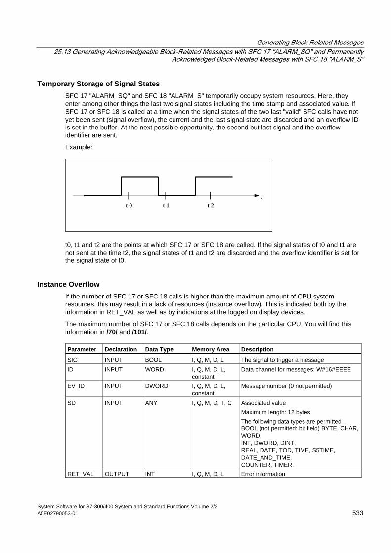
Generating Block-Related Messages 25.13 Generating Acknowledgeable Block-Related Messages with SFC 17 "ALARM_SQ" and Permanently
Acknowledged Block-Related Messages with SFC 18 "ALARM_S"
System Software for S7-300/400 System and Standard Functions Volume 2/2 A5E02790053-01 533
Temporary Storage of Signal States SFC 17 "ALARM_SQ" and SFC 18 "ALARM_S" temporarily occupy system resources. Here, they enter among other things the last two signal states including the time stamp and associated value. If SFC 17 or SFC 18 is called at a time when the signal states of the two last "valid" SFC calls have not yet been sent (signal overflow), the current and the last signal state are discarded and an overflow ID is set in the buffer. At the next possible opportunity, the second but last signal and the overflow identifier are sent.
Example:
tt 1 t 2t 0
t0, t1 and t2 are the points at which SFC 17 or SFC 18 are called. If the signal states of t0 and t1 are not sent at the time t2, the signal states of t1 and t2 are discarded and the overflow identifier is set for the signal state of t0.
Instance Overflow If the number of SFC 17 or SFC 18 calls is higher than the maximum amount of CPU system resources, this may result in a lack of resources (instance overflow). This is indicated both by the information in RET_VAL as well as by indications at the logged on display devices.
The maximum number of SFC 17 or SFC 18 calls depends on the particular CPU. You will find this information in /70/ and /101/. Parameter Declaration Data Type Memory Area Description
SIG INPUT BOOL I, Q, M, D, L The signal to trigger a message ID INPUT WORD I, Q, M, D, L,
constant Data channel for messages: W#16#EEEE
EV_ID INPUT DWORD I, Q, M, D, L, constant
Message number (0 not permitted)
SD INPUT ANY I, Q, M, D, T, C Associated value Maximum length: 12 bytes The following data types are permitted BOOL (not permitted: bit field) BYTE, CHAR, WORD, INT, DWORD, DINT, REAL, DATE, TOD, TIME, S5TIME, DATE_AND_TIME, COUNTER, TIMER.
RET_VAL OUTPUT INT I, Q, M, D, L Error information
Generating Block-Related Messages 25.13 Generating Acknowledgeable Block-Related Messages with SFC 17 "ALARM_SQ" and Permanently Acknowledged Block-Related Messages with SFC 18 "ALARM_S"
System Software for S7-300/400 System and Standard Functions Volume 2/2 534 Reference Manual, 05/2010, A5E02790053-01
Error Information Error Code (W#16#...) Explanation
0000 No error occurred. 0001 • The associated value is longer than the maximum permitted length or
• Access to the user memory is not possible (for example, access to a deleted DB). The message is sent.
• The associated value points to a value in the local data area. The message is sent. (S7-400 only)
0002 Warning: the last free message acknowledgment memory has been used. (S7-400 only)
8081 The specified EV_ID is outside the permitted range. 8082 Loss of messages since your CPU has no more resources for generating block-
related messages by SFCs. 8083 Message loss since the same signal change already exists but could not yet be
sent (signal overflow). 8084 The signal that triggered the message (SIG) had the same value at the current
SFC 17 or SFC 18 call as at the last call. 8085 No logon for the specified EV_ID 8086 An SFC call for the specified EV_ID is already being executed in a lower priority
class. 8087 When SFC 17 or SFC 18 were first called, the message trigger signal had the
value 0. 8088 The specified EV_ID is already being used by another system resource (to SFC 17,
18, 107, 108). 8xyy General error information, see Evaluating Errors with the Output Parameter
RET_VAL
Generating Block-Related Messages 25.14 Querying the Acknowledgment Status of the Last ALARM_SQ/ALARM_DQ Entering Event Message with
SFC 19 "ALARM_SC"
System Software for S7-300/400 System and Standard Functions Volume 2/2 A5E02790053-01 535
25.14 Querying the Acknowledgment Status of the Last ALARM_SQ/ALARM_DQ Entering Event Message with SFC 19 "ALARM_SC"
Description With SFC 19 "ALARM_SC" you can query the following:
• The acknowledgment status of the last ALARM_SQ/ALARM_DQ entering state message and the status of the signal that triggered the message the last time that SFC 17 "ALARM_SQ"/SFC 107 "ALARM_DQ" was called, or
• The status of the signal that triggered the message the last time SFC 18 "ALARM_S"/SFC 108 "ALARM_D" was called.
Assuming that you assigned the message numbers during message configuration, the message or signal is referenced with a unique message number SFC 19 "ALARM_SC" accesses the temporarily occupied memory of SFC 17 or SFC 18/SFC 107/SFC 108.
Parameter Declaration Data Type Memory Area Description
EV_ID INPUT DWORD I, Q, M, D, L, constant
Message number for the signal state at the last SFC call or the acknowledgment status of the last entering state message (only with SFC 17 and SFC 107!) that you want to query.
RET_VAL OUTPUT INT I, Q, M, D, L Error information STATE OUTPUT BOOL I, Q, M, D, L State of the signal that triggered the
message at the last SFC call Q_STATE OUTPUT BOOL I, Q, M, D, L If the specified EV_ID parameter belongs
to an SFC 18/SFC 108 call: 1 If the specified EV_ID parameter belongs
to an SFC 17/SFC 107 call: acknowledgment status of the last entering state message: 0: Not acknowledged 1: Acknowledged
Generating Block-Related Messages 25.14 Querying the Acknowledgment Status of the Last ALARM_SQ/ALARM_DQ Entering Event Message with SFC 19 "ALARM_SC"
System Software for S7-300/400 System and Standard Functions Volume 2/2 536 Reference Manual, 05/2010, A5E02790053-01
Error Information Error Code (W#16#...) Explanation
0000 No error occurred. 8081 The specified EV_ID is outside the permitted range. 8082 No memory is currently occupied for this EV_ID (possible cause: the
corresponding signal state was not yet 1, or the signal state has already returned to 0).
8xyy General error information, see Evaluating Errors with the Output Parameter RET_VAL
Generating Block-Related Messages 25.15 Generating Acknowledgeable and Permanently Acknowledged Block Related Messages with SFCs 107
"ALARM_DQ" and 108 "ALARM_D"
System Software for S7-300/400 System and Standard Functions Volume 2/2 A5E02790053-01 537
25.15 Generating Acknowledgeable and Permanently Acknowledged Block Related Messages with SFCs 107 "ALARM_DQ" and 108 "ALARM_D"
Description With every call the SFCs 107 "ALARM_DQ" and 108 "ALARM_D" generate a message to which you can append an associated value. Thus, you correspond with SFCs 17 "ALARM_SQ" and 18 "ALARM_S".
When generating messages with SFCs 107 "ALARM_DQ" and 108 "ALARM_D", the operating system temporarily occupies a system resource for the duration of the signal cycle.
The signal cycle time for SFC 108 "ALARM_D" starts at the SFC call with SIG=1 and ends at a new call with SIG=0. This interval for SFC 107 "ALARM_DQ" may be extended by the time expiring until the incoming signal is acknowledged at a logged in displaying device.
For SFC 108 "ALARM_D", the signal cycle lasts from the SFC call SIG=1 until another call with SIG=0. For SFC 107 "ALARM_DQ", this time period also includes the time until the incoming signal is acknowledged by one of the reported display devices, if necessary.
If, during the signal cycle, the message-generating block is overloaded or deleted, the associated system resource remains occupied until the next restart (warm restart).
The additional functionality of SFCs 107 "ALARM_DQ" and 108 "ALARM_D" compared to SFCs 17 and 18 is now that you can manage these occupied system resources:
• With the help of SFC 105 "READ_SI" you can fetch information related to occupied system resources.
• With SFC 106 "DEL_SI" you can release occupied system resources again. This is of special significance for permanently occupied system resources. A currently occupied system resource, for example, stays occupied until the next restart (warm restart) if you, in the course of a program change, delete an FB call that contains SFC107 or SFC108 calls . When you change the program, and reload an FB with SFC 107 or SFC 108 calls, it may happen that the SFCs 107 and 108 do not generate anymore messages.
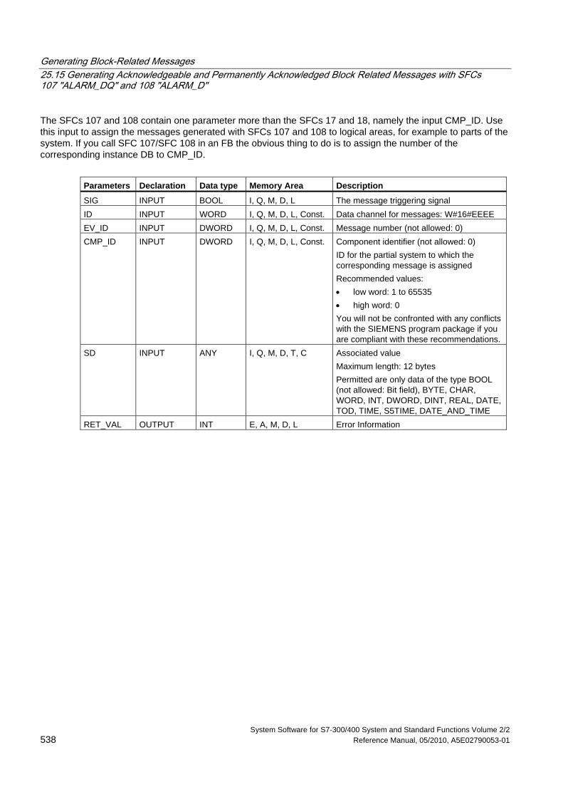
Generating Block-Related Messages 25.15 Generating Acknowledgeable and Permanently Acknowledged Block Related Messages with SFCs 107 "ALARM_DQ" and 108 "ALARM_D"
System Software for S7-300/400 System and Standard Functions Volume 2/2 538 Reference Manual, 05/2010, A5E02790053-01
The SFCs 107 and 108 contain one parameter more than the SFCs 17 and 18, namely the input CMP_ID. Use this input to assign the messages generated with SFCs 107 and 108 to logical areas, for example to parts of the system. If you call SFC 107/SFC 108 in an FB the obvious thing to do is to assign the number of the corresponding instance DB to CMP_ID.
Parameters Declaration Data type Memory Area Description
SIG INPUT BOOL I, Q, M, D, L The message triggering signal ID INPUT WORD I, Q, M, D, L, Const. Data channel for messages: W#16#EEEE EV_ID INPUT DWORD I, Q, M, D, L, Const. Message number (not allowed: 0) CMP_ID INPUT DWORD I, Q, M, D, L, Const. Component identifier (not allowed: 0)
ID for the partial system to which the corresponding message is assigned Recommended values: • low word: 1 to 65535 • high word: 0 You will not be confronted with any conflicts with the SIEMENS program package if you are compliant with these recommendations.
SD INPUT ANY I, Q, M, D, T, C Associated value Maximum length: 12 bytes Permitted are only data of the type BOOL (not allowed: Bit field), BYTE, CHAR, WORD, INT, DWORD, DINT, REAL, DATE, TOD, TIME, S5TIME, DATE_AND_TIME
RET_VAL OUTPUT INT E, A, M, D, L Error Information

Generating Block-Related Messages 25.15 Generating Acknowledgeable and Permanently Acknowledged Block Related Messages with SFCs 107
"ALARM_DQ" and 108 "ALARM_D"
System Software for S7-300/400 System and Standard Functions Volume 2/2 A5E02790053-01 539
Error Information Error code (W#16#...):
Explanation
0000 No error occurred. 0001 • The length of the associated value exceeds the maximum permissible
length, or • Access to user memory not possible (for example, access to deleted DB)
The activated message is sent. • The associated value points to a value in the local data area. The message
is sent. (S7-400 only) 0002 Warning: The last free message acknowledge memory was occupied.
(S7-400 only) 8081 The specified EV_ID lies outside the valid range. 8082 Message loss because your CPU has no more resource for generating block
related messages with SFCs. 8083 Message loss, the same signal transition is already present but could not be
sent yet (signal overflow). 8084 With the current and the previous SFC 107-/SFC-108 call the message
triggering signal SIG has the same value. 8085 There is no logon for the specified EV_ID. 8086 An SFC call for the specified EV_ID is already being processed in a lower
priority class. 8087 At the initial call of SFC 107/SFC 108 the message triggering signal had the
value 0. 8088 The specified EV_ID is already in use by another system resource (to SFC 17,
18, 107, 108). 8089 You have assigned the value 0 to CMP_ID. 8xyy General error information, see Evaluating Errors with the Output Parameter
RET_VAL
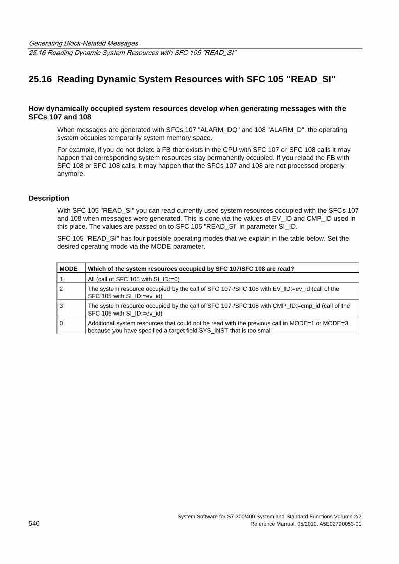
Generating Block-Related Messages 25.16 Reading Dynamic System Resources with SFC 105 "READ_SI"
System Software for S7-300/400 System and Standard Functions Volume 2/2 540 Reference Manual, 05/2010, A5E02790053-01
25.16 Reading Dynamic System Resources with SFC 105 "READ_SI"
How dynamically occupied system resources develop when generating messages with the SFCs 107 and 108
When messages are generated with SFCs 107 "ALARM_DQ" and 108 "ALARM_D", the operating system occupies temporarily system memory space.
For example, if you do not delete a FB that exists in the CPU with SFC 107 or SFC 108 calls it may happen that corresponding system resources stay permanently occupied. If you reload the FB with SFC 108 or SFC 108 calls, it may happen that the SFCs 107 and 108 are not processed properly anymore.
Description With SFC 105 "READ_SI" you can read currently used system resources occupied with the SFCs 107 and 108 when messages were generated. This is done via the values of EV_ID and CMP_ID used in this place. The values are passed on to SFC 105 "READ_SI" in parameter SI_ID.
SFC 105 "READ_SI" has four possible operating modes that we explain in the table below. Set the desired operating mode via the MODE parameter.
MODE Which of the system resources occupied by SFC 107/SFC 108 are read?
1 All (call of SFC 105 with SI_ID:=0) 2 The system resource occupied by the call of SFC 107-/SFC 108 with EV_ID:=ev_id (call of the
SFC 105 with SI_ID:=ev_id) 3 The system resource occupied by the call of SFC 107-/SFC 108 with CMP_ID:=cmp_id (call of the
SFC 105 with SI_ID:=ev_id) 0 Additional system resources that could not be read with the previous call in MODE=1 or MODE=3
because you have specified a target field SYS_INST that is too small
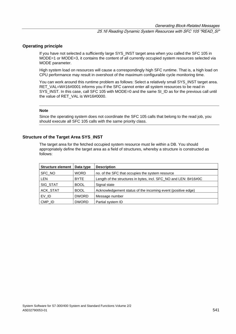
Generating Block-Related Messages 25.16 Reading Dynamic System Resources with SFC 105 "READ_SI"
System Software for S7-300/400 System and Standard Functions Volume 2/2 A5E02790053-01 541
Operating principle If you have not selected a sufficiently large SYS_INST target area when you called the SFC 105 in MODE=1 or MODE=3, it contains the content of all currently occupied system resources selected via MODE parameter.
High system load on resources will cause a correspondingly high SFC runtime. That is, a high load on CPU performance may result in overshoot of the maximum configurable cycle monitoring time.
You can work around this runtime problem as follows: Select a relatively small SYS_INST target area. RET_VAL=W#16#0001 informs you if the SFC cannot enter all system resources to be read in SYS_INST. In this case, call SFC 105 with MODE=0 and the same SI_ID as for the previous call until the value of RET_VAL is W#16#0000.
Note
Since the operating system does not coordinate the SFC 105 calls that belong to the read job, you should execute all SFC 105 calls with the same priority class.
Structure of the Target Area SYS_INST The target area for the fetched occupied system resource must lie within a DB. You should appropriately define the target area as a field of structures, whereby a structure is constructed as follows:
Structure element Data type Description
SFC_NO WORD no. of the SFC that occupies the system resource LEN BYTE Length of the structures in bytes, incl. SFC_NO and LEN: B#16#0C SIG_STAT BOOL Signal state ACK_STAT BOOL Acknowledgement status of the incoming event (positive edge) EV_ID DWORD Message number CMP_ID DWORD Partial system ID
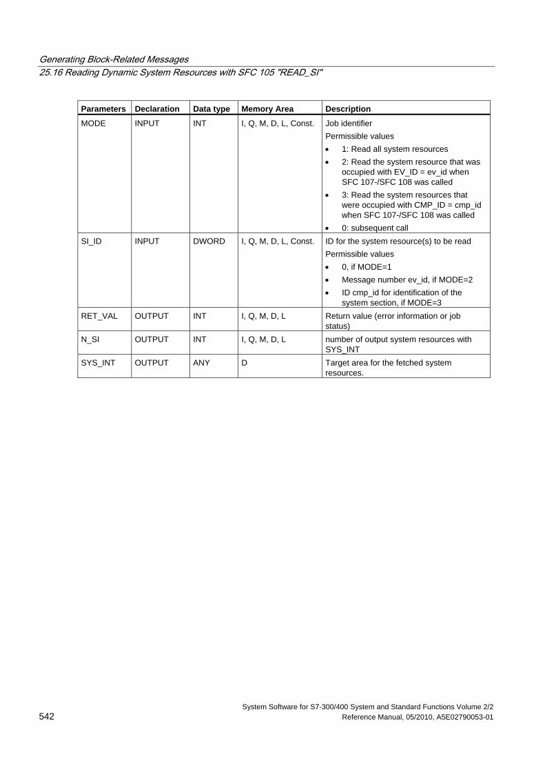
Generating Block-Related Messages 25.16 Reading Dynamic System Resources with SFC 105 "READ_SI"
System Software for S7-300/400 System and Standard Functions Volume 2/2 542 Reference Manual, 05/2010, A5E02790053-01
Parameters Declaration Data type Memory Area Description
MODE INPUT INT I, Q, M, D, L, Const. Job identifier Permissible values • 1: Read all system resources • 2: Read the system resource that was
occupied with EV_ID = ev_id when SFC 107-/SFC 108 was called
• 3: Read the system resources that were occupied with CMP_ID = cmp_id when SFC 107-/SFC 108 was called
• 0: subsequent call SI_ID INPUT DWORD I, Q, M, D, L, Const. ID for the system resource(s) to be read
Permissible values • 0, if MODE=1 • Message number ev_id, if MODE=2 • ID cmp_id for identification of the
system section, if MODE=3 RET_VAL OUTPUT INT I, Q, M, D, L Return value (error information or job
status) N_SI OUTPUT INT I, Q, M, D, L number of output system resources with
SYS_INT SYS_INT OUTPUT ANY D Target area for the fetched system
resources.
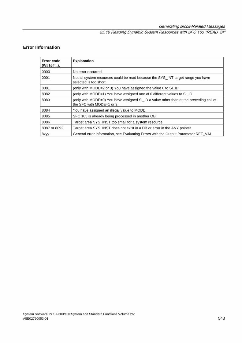
Generating Block-Related Messages 25.16 Reading Dynamic System Resources with SFC 105 "READ_SI"
System Software for S7-300/400 System and Standard Functions Volume 2/2 A5E02790053-01 543
Error Information Error code (W#16#...):
Explanation
0000 No error occurred. 0001 Not all system resources could be read because the SYS_INT target range you have
selected is too short. 8081 (only with MODE=2 or 3) You have assigned the value 0 to SI_ID. 8082 (only with MODE=1) You have assigned one of 0 different values to SI_ID. 8083 (only with MODE=0) You have assigned SI_ID a value other than at the preceding call of
the SFC with MODE=1 or 3. 8084 You have assigned an illegal value to MODE. 8085 SFC 105 is already being processed in another OB. 8086 Target area SYS_INST too small for a system resource. 8087 or 8092 Target area SYS_INST does not exist in a DB or error in the ANY pointer. 8xyy General error information, see Evaluating Errors with the Output Parameter RET_VAL
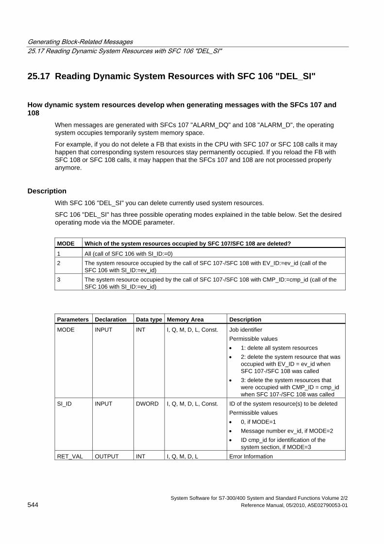
Generating Block-Related Messages 25.17 Reading Dynamic System Resources with SFC 106 "DEL_SI"
System Software for S7-300/400 System and Standard Functions Volume 2/2 544 Reference Manual, 05/2010, A5E02790053-01
25.17 Reading Dynamic System Resources with SFC 106 "DEL_SI"
How dynamic system resources develop when generating messages with the SFCs 107 and 108
When messages are generated with SFCs 107 "ALARM_DQ" and 108 "ALARM_D", the operating system occupies temporarily system memory space.
For example, if you do not delete a FB that exists in the CPU with SFC 107 or SFC 108 calls it may happen that corresponding system resources stay permanently occupied. If you reload the FB with SFC 108 or SFC 108 calls, it may happen that the SFCs 107 and 108 are not processed properly anymore.
Description With SFC 106 "DEL_SI" you can delete currently used system resources.
SFC 106 "DEL_SI" has three possible operating modes explained in the table below. Set the desired operating mode via the MODE parameter.
MODE Which of the system resources occupied by SFC 107/SFC 108 are deleted?
1 All (call of SFC 106 with SI_ID:=0) 2 The system resource occupied by the call of SFC 107-/SFC 108 with EV_ID:=ev_id (call of the
SFC 106 with SI_ID:=ev_id) 3 The system resource occupied by the call of SFC 107-/SFC 108 with CMP_ID:=cmp_id (call of the
SFC 106 with SI_ID:=ev_id)
Parameters Declaration Data type Memory Area Description
MODE INPUT INT I, Q, M, D, L, Const. Job identifier Permissible values • 1: delete all system resources • 2: delete the system resource that was
occupied with EV_ID = ev_id when SFC 107-/SFC 108 was called
• 3: delete the system resources that were occupied with CMP_ID = cmp_id when SFC 107-/SFC 108 was called
SI_ID INPUT DWORD I, Q, M, D, L, Const. ID of the system resource(s) to be deleted Permissible values • 0, if MODE=1 • Message number ev_id, if MODE=2 • ID cmp_id for identification of the
system section, if MODE=3 RET_VAL OUTPUT INT I, Q, M, D, L Error Information
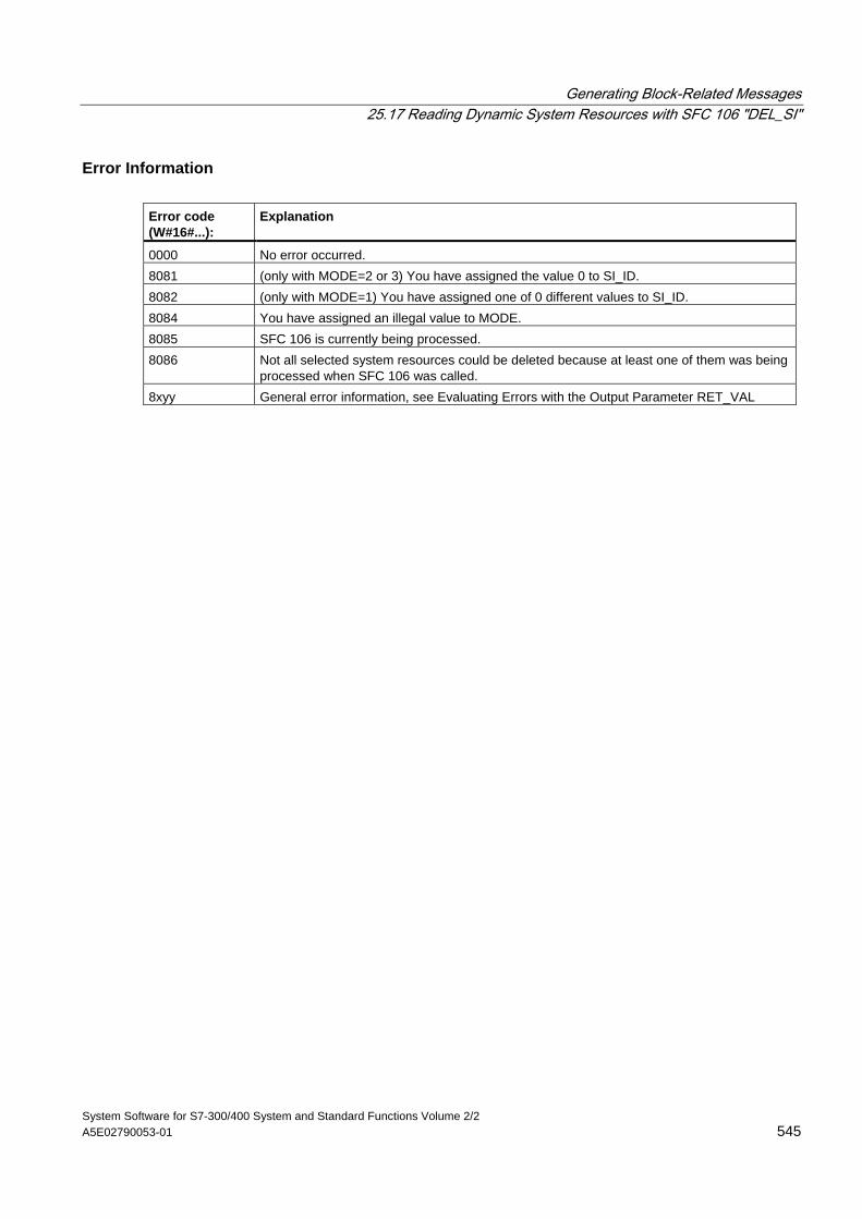
Generating Block-Related Messages 25.17 Reading Dynamic System Resources with SFC 106 "DEL_SI"
System Software for S7-300/400 System and Standard Functions Volume 2/2 A5E02790053-01 545
Error Information Error code (W#16#...):
Explanation
0000 No error occurred. 8081 (only with MODE=2 or 3) You have assigned the value 0 to SI_ID. 8082 (only with MODE=1) You have assigned one of 0 different values to SI_ID. 8084 You have assigned an illegal value to MODE. 8085 SFC 106 is currently being processed. 8086 Not all selected system resources could be deleted because at least one of them was being
processed when SFC 106 was called. 8xyy General error information, see Evaluating Errors with the Output Parameter RET_VAL

System Software for S7-300/400 System and Standard Functions Volume 2/2 Reference Manual, 05/2010, A5E02790053-01 547
26 IEC Timers and IEC Counters
26.1 Generating a Pulse with SFB 3 "TP"
Description SFB 3 "TP" generates a pulse with the length PT. The timer runs only in the STARTUP and RUN modes.
A rising signal edge at input IN starts the pulse. Output Q remains set for the time PT regardless of changes in the input signal (in other words even when the IN input changes back from 0 to 1 before the time PT has expired).The ET output provides the time for which output Q has already been set. The maximum value of the ET output is the value of the PT input. Output ET is reset when input IN changes to 0, however, not before the time PT has expired.
SFB 3 "TP" complies with the IEC 1131-3 standard.
The operating system resets the instances of SFB 3 "TP" during a cold restart. If you want instances of this SFB to be initialized following a warm restart, you must call SFB 3 with PT = 0 ms in OB100. If instances of this SFB are located within another block, you can reset these instances, for example, by initializing the higher-level block.
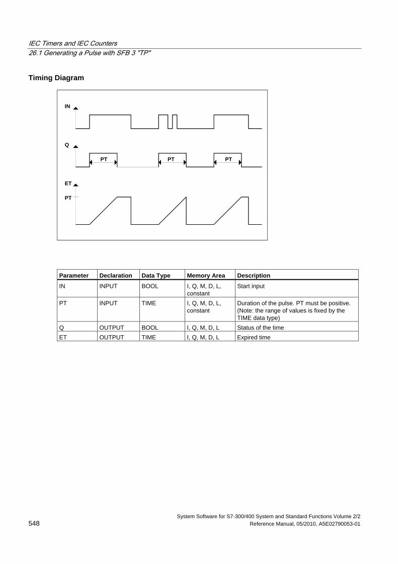
IEC Timers and IEC Counters 26.1 Generating a Pulse with SFB 3 "TP"
System Software for S7-300/400 System and Standard Functions Volume 2/2 548 Reference Manual, 05/2010, A5E02790053-01
Timing Diagram
PT
ET
Q
IN
PT
PTPT
Parameter Declaration Data Type Memory Area Description
IN INPUT BOOL I, Q, M, D, L, constant
Start input
PT INPUT TIME I, Q, M, D, L, constant
Duration of the pulse. PT must be positive. (Note: the range of values is fixed by the TIME data type)
Q OUTPUT BOOL I, Q, M, D, L Status of the time ET OUTPUT TIME I, Q, M, D, L Expired time
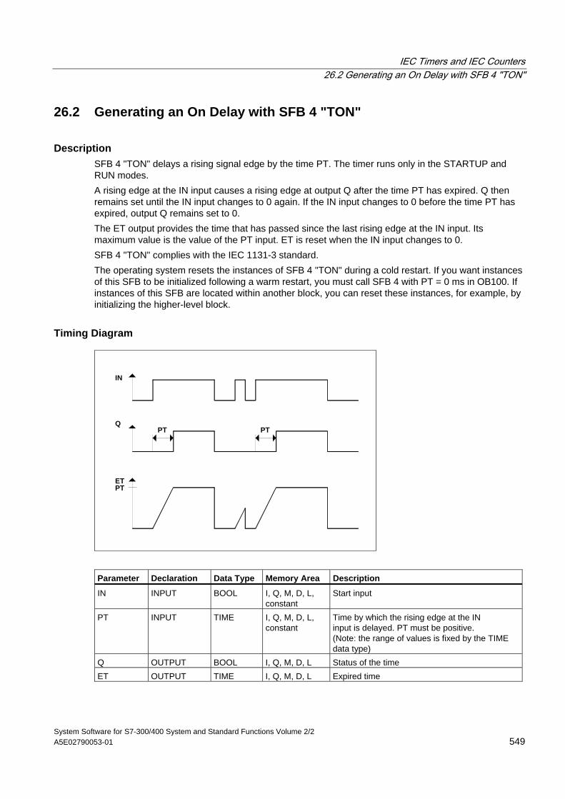
IEC Timers and IEC Counters 26.2 Generating an On Delay with SFB 4 "TON"
System Software for S7-300/400 System and Standard Functions Volume 2/2 A5E02790053-01 549
26.2 Generating an On Delay with SFB 4 "TON"
Description SFB 4 "TON" delays a rising signal edge by the time PT. The timer runs only in the STARTUP and RUN modes. A rising edge at the IN input causes a rising edge at output Q after the time PT has expired. Q then remains set until the IN input changes to 0 again. If the IN input changes to 0 before the time PT has expired, output Q remains set to 0. The ET output provides the time that has passed since the last rising edge at the IN input. Its maximum value is the value of the PT input. ET is reset when the IN input changes to 0. SFB 4 "TON" complies with the IEC 1131-3 standard. The operating system resets the instances of SFB 4 "TON" during a cold restart. If you want instances of this SFB to be initialized following a warm restart, you must call SFB 4 with PT = 0 ms in OB100. If instances of this SFB are located within another block, you can reset these instances, for example, by initializing the higher-level block.
Timing Diagram
ET
Q
IN
PT
PT PT
Parameter Declaration Data Type Memory Area Description
IN INPUT BOOL I, Q, M, D, L, constant
Start input
PT INPUT TIME I, Q, M, D, L, constant
Time by which the rising edge at the IN input is delayed. PT must be positive. (Note: the range of values is fixed by the TIME data type)
Q OUTPUT BOOL I, Q, M, D, L Status of the time ET OUTPUT TIME I, Q, M, D, L Expired time
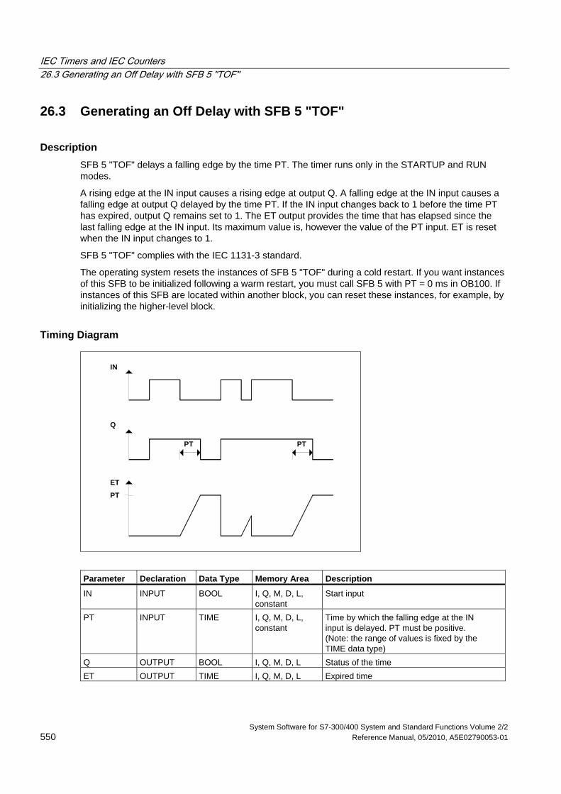
IEC Timers and IEC Counters 26.3 Generating an Off Delay with SFB 5 "TOF"
System Software for S7-300/400 System and Standard Functions Volume 2/2 550 Reference Manual, 05/2010, A5E02790053-01
26.3 Generating an Off Delay with SFB 5 "TOF"
Description SFB 5 "TOF" delays a falling edge by the time PT. The timer runs only in the STARTUP and RUN modes.
A rising edge at the IN input causes a rising edge at output Q. A falling edge at the IN input causes a falling edge at output Q delayed by the time PT. If the IN input changes back to 1 before the time PT has expired, output Q remains set to 1. The ET output provides the time that has elapsed since the last falling edge at the IN input. Its maximum value is, however the value of the PT input. ET is reset when the IN input changes to 1.
SFB 5 "TOF" complies with the IEC 1131-3 standard.
The operating system resets the instances of SFB 5 "TOF" during a cold restart. If you want instances of this SFB to be initialized following a warm restart, you must call SFB 5 with PT = 0 ms in OB100. If instances of this SFB are located within another block, you can reset these instances, for example, by initializing the higher-level block.
Timing Diagram
PT PT
ET
Q
IN
PT
Parameter Declaration Data Type Memory Area Description
IN INPUT BOOL I, Q, M, D, L, constant
Start input
PT INPUT TIME I, Q, M, D, L, constant
Time by which the falling edge at the IN input is delayed. PT must be positive. (Note: the range of values is fixed by the TIME data type)
Q OUTPUT BOOL I, Q, M, D, L Status of the time ET OUTPUT TIME I, Q, M, D, L Expired time
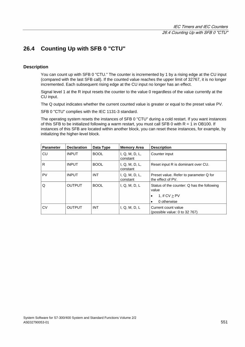
IEC Timers and IEC Counters 26.4 Counting Up with SFB 0 "CTU"
System Software for S7-300/400 System and Standard Functions Volume 2/2 A5E02790053-01 551
26.4 Counting Up with SFB 0 "CTU"
Description You can count up with SFB 0 "CTU." The counter is incremented by 1 by a rising edge at the CU input (compared with the last SFB call). If the counted value reaches the upper limit of 32767, it is no longer incremented. Each subsequent rising edge at the CU input no longer has an effect.
Signal level 1 at the R input resets the counter to the value 0 regardless of the value currently at the CU input.
The Q output indicates whether the current counted value is greater or equal to the preset value PV.
SFB 0 "CTU" complies with the IEC 1131-3 standard.
The operating system resets the instances of SFB 0 "CTU" during a cold restart. If you want instances of this SFB to be initialized following a warm restart, you must call SFB 0 with R = 1 in OB100. If instances of this SFB are located within another block, you can reset these instances, for example, by initializing the higher-level block.
Parameter Declaration Data Type Memory Area Description
CU INPUT BOOL I, Q, M, D, L, constant
Counter input
R INPUT BOOL I, Q, M, D, L, constant
Reset input R is dominant over CU.
PV INPUT INT I, Q, M, D, L, constant
Preset value. Refer to parameter Q for the effect of PV.
Q OUTPUT BOOL I, Q, M, D, L Status of the counter: Q has the following value • 1, if CV > PV • 0 otherwise
CV OUTPUT INT I, Q, M, D, L Current count value (possible value: 0 to 32 767)
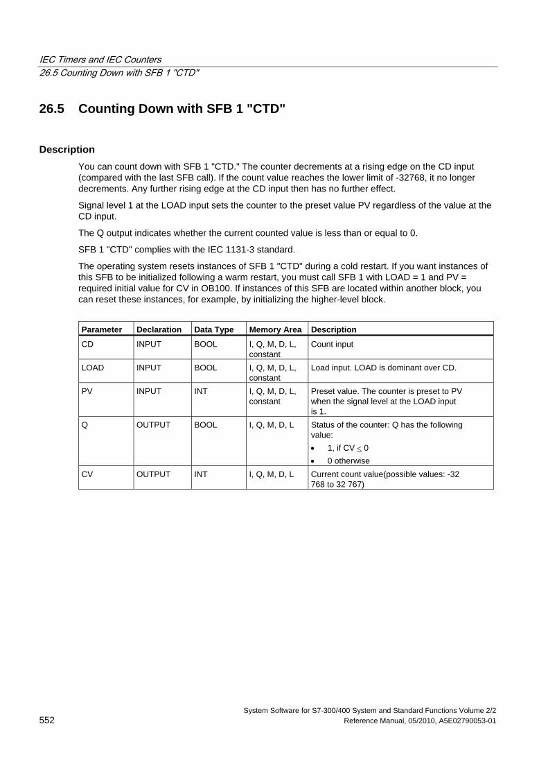
IEC Timers and IEC Counters 26.5 Counting Down with SFB 1 "CTD"
System Software for S7-300/400 System and Standard Functions Volume 2/2 552 Reference Manual, 05/2010, A5E02790053-01
26.5 Counting Down with SFB 1 "CTD"
Description You can count down with SFB 1 "CTD." The counter decrements at a rising edge on the CD input (compared with the last SFB call). If the count value reaches the lower limit of -32768, it no longer decrements. Any further rising edge at the CD input then has no further effect.
Signal level 1 at the LOAD input sets the counter to the preset value PV regardless of the value at the CD input.
The Q output indicates whether the current counted value is less than or equal to 0.
SFB 1 "CTD" complies with the IEC 1131-3 standard.
The operating system resets instances of SFB 1 "CTD" during a cold restart. If you want instances of this SFB to be initialized following a warm restart, you must call SFB 1 with LOAD = 1 and PV = required initial value for CV in OB100. If instances of this SFB are located within another block, you can reset these instances, for example, by initializing the higher-level block.
Parameter Declaration Data Type Memory Area Description
CD INPUT BOOL I, Q, M, D, L, constant
Count input
LOAD INPUT BOOL I, Q, M, D, L, constant
Load input. LOAD is dominant over CD.
PV INPUT INT I, Q, M, D, L, constant
Preset value. The counter is preset to PV when the signal level at the LOAD input is 1.
Q OUTPUT BOOL I, Q, M, D, L Status of the counter: Q has the following value: • 1, if CV < 0 • 0 otherwise
CV OUTPUT INT I, Q, M, D, L Current count value(possible values: -32 768 to 32 767)
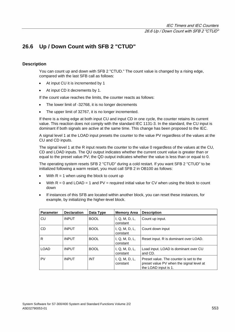
IEC Timers and IEC Counters 26.6 Up / Down Count with SFB 2 "CTUD"
System Software for S7-300/400 System and Standard Functions Volume 2/2 A5E02790053-01 553
26.6 Up / Down Count with SFB 2 "CTUD"
Description You can count up and down with SFB 2 "CTUD." The count value is changed by a rising edge, compared with the last SFB call as follows:
• At input CU it is incremented by 1
• At input CD it decrements by 1.
If the count value reaches the limits, the counter reacts as follows:
• The lower limit of -32768, it is no longer decrements
• The upper limit of 32767, it is no longer incremented.
If there is a rising edge at both input CU and input CD in one cycle, the counter retains its current value. This reaction does not comply with the standard IEC 1131-3. In the standard, the CU input is dominant if both signals are active at the same time. This change has been proposed to the IEC.
A signal level 1 at the LOAD input presets the counter to the value PV regardless of the values at the CU and CD inputs.
The signal level 1 at the R input resets the counter to the value 0 regardless of the values at the CU, CD and LOAD inputs. The QU output indicates whether the current count value is greater than or equal to the preset value PV; the QD output indicates whether the value is less than or equal to 0.
The operating system resets SFB 2 "CTUD" during a cold restart. If you want SFB 2 "CTUD" to be initialized following a warm restart, you must call SFB 2 in OB100 as follows:
• With R = 1 when using the block to count up
• With R = 0 and LOAD = 1 and PV = required initial value for CV when using the block to count down
• If instances of this SFB are located within another block, you can reset these instances, for example, by initializing the higher-level block.
Parameter Declaration Data Type Memory Area Description
CU INPUT BOOL I, Q, M, D, L, constant
Count up input.
CD INPUT BOOL I, Q, M, D, L, constant
Count down input
R INPUT BOOL I, Q, M, D, L, constant
Reset input. R is dominant over LOAD.
LOAD INPUT BOOL I, Q, M, D, L, constant
Load input. LOAD is dominant over CU and CD.
PV INPUT INT I, Q, M, D, L, constant
Preset value. The counter is set to the preset value PV when the signal level at the LOAD input is 1.
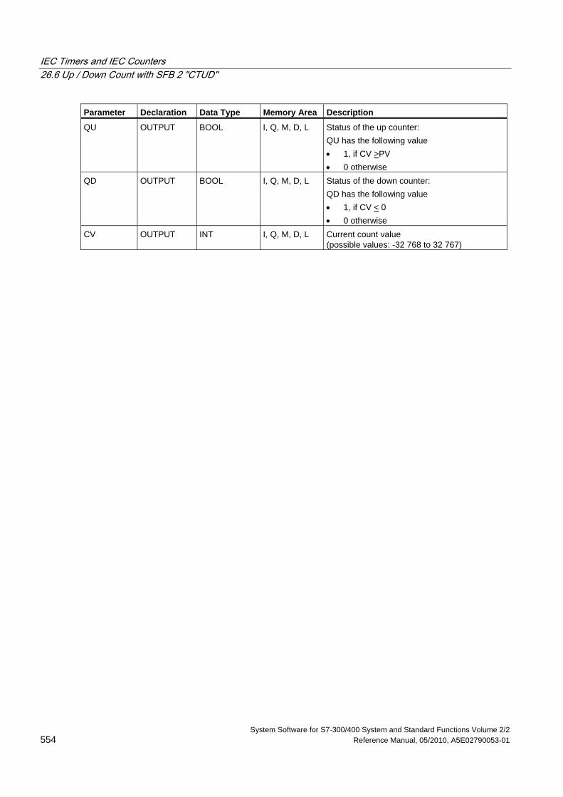
IEC Timers and IEC Counters 26.6 Up / Down Count with SFB 2 "CTUD"
System Software for S7-300/400 System and Standard Functions Volume 2/2 554 Reference Manual, 05/2010, A5E02790053-01
Parameter Declaration Data Type Memory Area Description
QU OUTPUT BOOL I, Q, M, D, L Status of the up counter: QU has the following value • 1, if CV >PV • 0 otherwise
QD OUTPUT BOOL I, Q, M, D, L Status of the down counter: QD has the following value • 1, if CV < 0 • 0 otherwise
CV OUTPUT INT I, Q, M, D, L Current count value (possible values: -32 768 to 32 767)
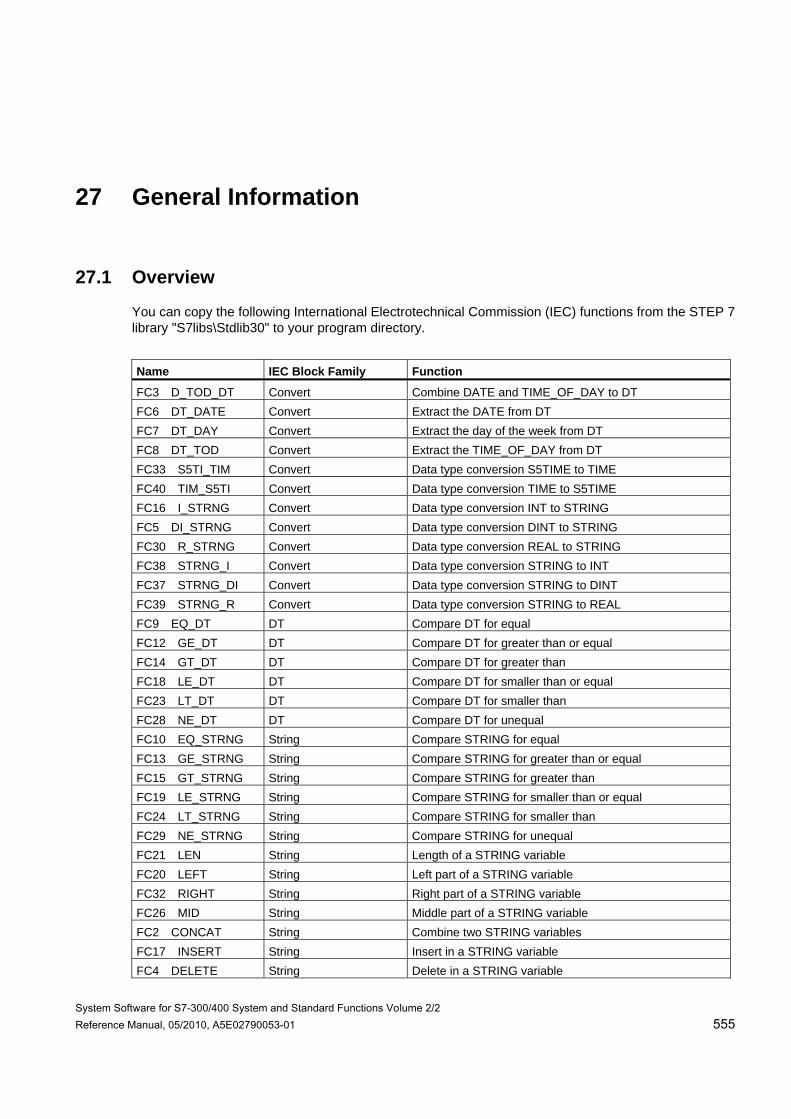
System Software for S7-300/400 System and Standard Functions Volume 2/2 Reference Manual, 05/2010, A5E02790053-01 555
27 General Information
27.1 Overview
You can copy the following International Electrotechnical Commission (IEC) functions from the STEP 7 library "S7libs\Stdlib30" to your program directory.
Name IEC Block Family Function
FC3 D_TOD_DT Convert Combine DATE and TIME_OF_DAY to DT FC6 DT_DATE Convert Extract the DATE from DT FC7 DT_DAY Convert Extract the day of the week from DT FC8 DT_TOD Convert Extract the TIME_OF_DAY from DT FC33 S5TI_TIM Convert Data type conversion S5TIME to TIME FC40 TIM_S5TI Convert Data type conversion TIME to S5TIME FC16 I_STRNG Convert Data type conversion INT to STRING FC5 DI_STRNG Convert Data type conversion DINT to STRING FC30 R_STRNG Convert Data type conversion REAL to STRING FC38 STRNG_I Convert Data type conversion STRING to INT FC37 STRNG_DI Convert Data type conversion STRING to DINT FC39 STRNG_R Convert Data type conversion STRING to REAL FC9 EQ_DT DT Compare DT for equal FC12 GE_DT DT Compare DT for greater than or equal FC14 GT_DT DT Compare DT for greater than FC18 LE_DT DT Compare DT for smaller than or equal FC23 LT_DT DT Compare DT for smaller than FC28 NE_DT DT Compare DT for unequal FC10 EQ_STRNG String Compare STRING for equal FC13 GE_STRNG String Compare STRING for greater than or equal FC15 GT_STRNG String Compare STRING for greater than FC19 LE_STRNG String Compare STRING for smaller than or equal FC24 LT_STRNG String Compare STRING for smaller than FC29 NE_STRNG String Compare STRING for unequal FC21 LEN String Length of a STRING variable FC20 LEFT String Left part of a STRING variable FC32 RIGHT String Right part of a STRING variable FC26 MID String Middle part of a STRING variable FC2 CONCAT String Combine two STRING variables FC17 INSERT String Insert in a STRING variable FC4 DELETE String Delete in a STRING variable
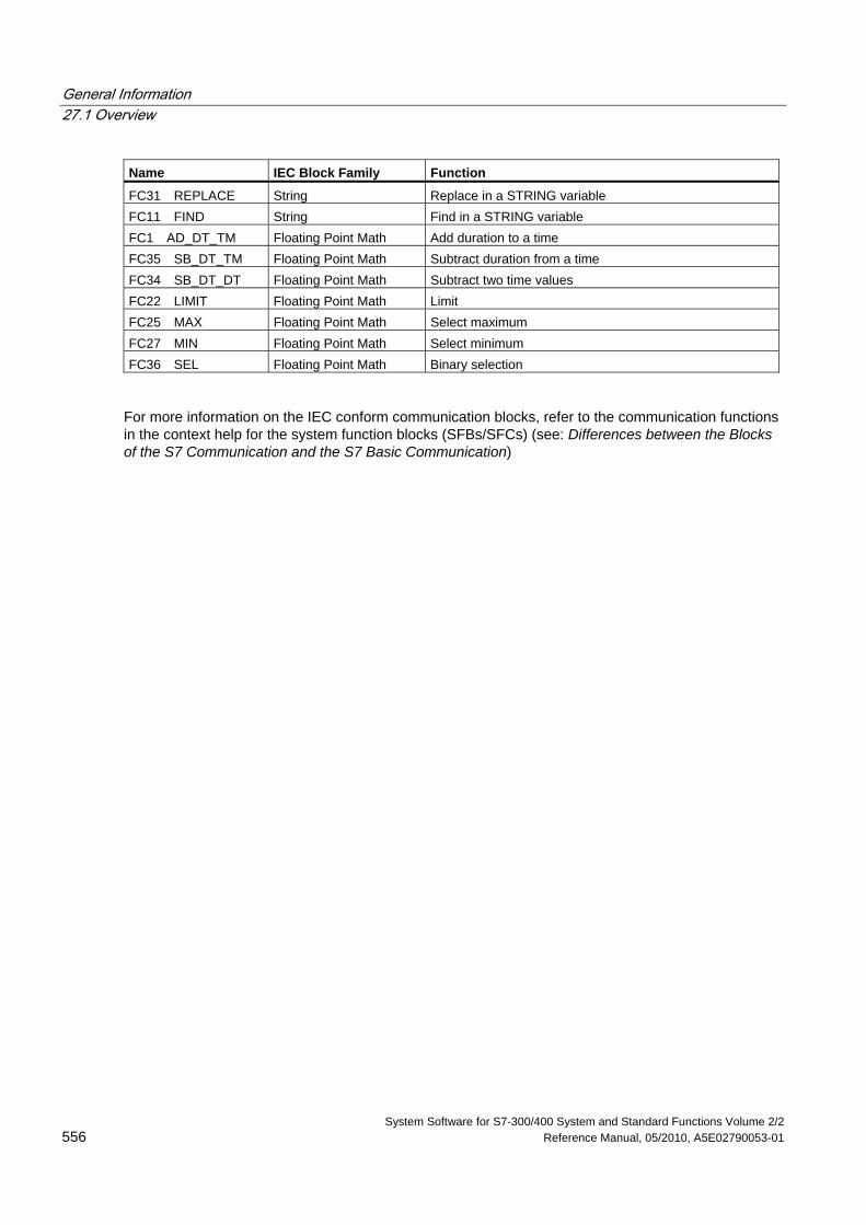
General Information 27.1 Overview
System Software for S7-300/400 System and Standard Functions Volume 2/2 556 Reference Manual, 05/2010, A5E02790053-01
Name IEC Block Family Function
FC31 REPLACE String Replace in a STRING variable FC11 FIND String Find in a STRING variable FC1 AD_DT_TM Floating Point Math Add duration to a time FC35 SB_DT_TM Floating Point Math Subtract duration from a time FC34 SB_DT_DT Floating Point Math Subtract two time values FC22 LIMIT Floating Point Math Limit FC25 MAX Floating Point Math Select maximum FC27 MIN Floating Point Math Select minimum FC36 SEL Floating Point Math Binary selection
For more information on the IEC conform communication blocks, refer to the communication functions in the context help for the system function blocks (SFBs/SFCs) (see: Differences between the Blocks of the S7 Communication and the S7 Basic Communication)
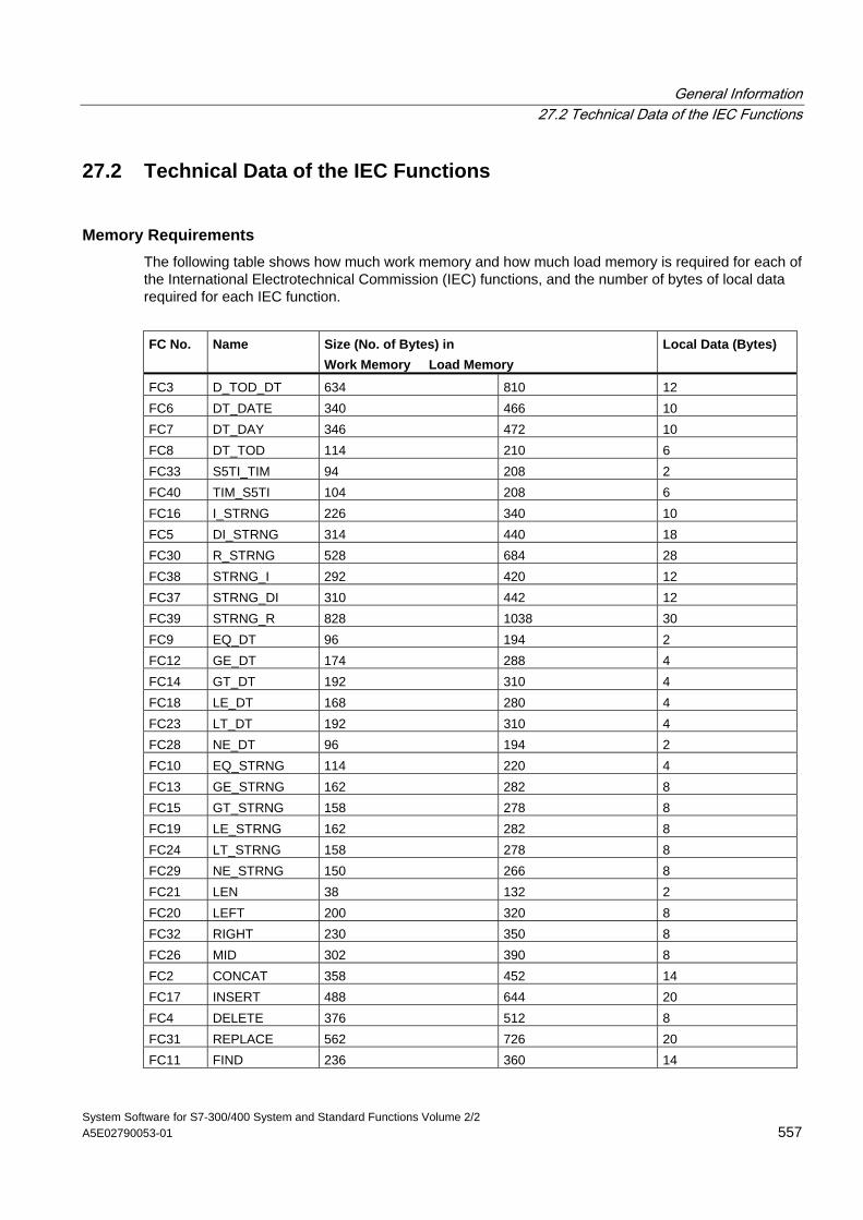
General Information 27.2 Technical Data of the IEC Functions
System Software for S7-300/400 System and Standard Functions Volume 2/2 A5E02790053-01 557
27.2 Technical Data of the IEC Functions
Memory Requirements The following table shows how much work memory and how much load memory is required for each of the International Electrotechnical Commission (IEC) functions, and the number of bytes of local data required for each IEC function.
FC No. Name Size (No. of Bytes) in
Work Memory Load Memory Local Data (Bytes)
FC3 D_TOD_DT 634 810 12 FC6 DT_DATE 340 466 10 FC7 DT_DAY 346 472 10 FC8 DT_TOD 114 210 6 FC33 S5TI_TIM 94 208 2 FC40 TIM_S5TI 104 208 6 FC16 I_STRNG 226 340 10 FC5 DI_STRNG 314 440 18 FC30 R_STRNG 528 684 28 FC38 STRNG_I 292 420 12 FC37 STRNG_DI 310 442 12 FC39 STRNG_R 828 1038 30 FC9 EQ_DT 96 194 2 FC12 GE_DT 174 288 4 FC14 GT_DT 192 310 4 FC18 LE_DT 168 280 4 FC23 LT_DT 192 310 4 FC28 NE_DT 96 194 2 FC10 EQ_STRNG 114 220 4 FC13 GE_STRNG 162 282 8 FC15 GT_STRNG 158 278 8 FC19 LE_STRNG 162 282 8 FC24 LT_STRNG 158 278 8 FC29 NE_STRNG 150 266 8 FC21 LEN 38 132 2 FC20 LEFT 200 320 8 FC32 RIGHT 230 350 8 FC26 MID 302 390 8 FC2 CONCAT 358 452 14 FC17 INSERT 488 644 20 FC4 DELETE 376 512 8 FC31 REPLACE 562 726 20 FC11 FIND 236 360 14
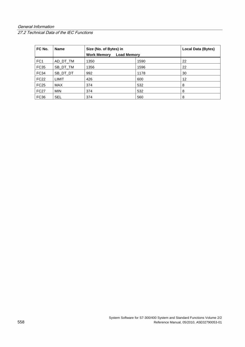
General Information 27.2 Technical Data of the IEC Functions
System Software for S7-300/400 System and Standard Functions Volume 2/2 558 Reference Manual, 05/2010, A5E02790053-01
FC No. Name Size (No. of Bytes) in Work Memory Load Memory
Local Data (Bytes)
FC1 AD_DT_TM 1350 1590 22 FC35 SB_DT_TM 1356 1596 22 FC34 SB_DT_DT 992 1178 30 FC22 LIMIT 426 600 12 FC25 MAX 374 532 8 FC27 MIN 374 532 8 FC36 SEL 374 560 8
General Information 27.3 Date and Time as Complex Data Types
System Software for S7-300/400 System and Standard Functions Volume 2/2 A5E02790053-01 559
27.3 Date and Time as Complex Data Types
Actual Parameters for DATE_AND_TIME The DATE_AND_TIME data type falls into the category of complex data types, along with ARRAY, STRING, and STRUCT. The permissible memory areas for complex data types are the data block (D) and local data (L) areas.
Because DATE_AND_TIME is a complex data type, when you use DATE_AND_TIME as a formal parameter in a statement, you can provide the actual parameter only in one of the following forms:
• A block-specific symbol from the variable declaration table for a specific block
• A symbolic name for a data block, such as "DB_sys_info.System_Time", made up of the following parts:
- A name defined in the symbol table for the number of the data block (for example, "DB_sys_info" for DB5)
- A name defined within the data block for the DATE_AND_TIME element (for example, "System_Time" for a variable of data type DATE_AND_TIME contained in DB5)
You cannot pass constants as actual parameters to formal parameters of the complex data types, including DATE_AND_TIME. Also, you cannot pass absolute addresses as actual parameters to DATE_AND_TIME.
General Information 27.4 Time-of-Day Functions
System Software for S7-300/400 System and Standard Functions Volume 2/2 560 Reference Manual, 05/2010, A5E02790053-01
27.4 Time-of-Day Functions
Description FC1 AD_DT_TM The function FC1 adds a duration (format TIME) to a time (format DT) and provides a new time (format DT) as the result. The time (parameter T) must be in the range from DT#1990-01-01-00:00:00.000 to DT#2089-12-31-23:59:59.999. The function does not run an input check. If the result of the addition is not within the valid range, the result is limited to the corresponding value and the binary result (BR) bit of the status word is set to ”0".
Parameter Declaration Data Type Memory Area Description
T INPUT DATE_AND_TIME D, L Time in format DT D INPUT TIME I, Q, M, D, L, Const. Duration in format TIME RET_VAL OUTPUT DATE_AND_TIME D, L Sum in format DT
You can assign only a symbolically defined variable for the input parameter T and the output parameter.
Description FC3 D_TOD_DT The function FC3 combines the data formats DATE and TIME_OF_DAY (TOD) together and converts these formats to the data type format DATE_AND_TIME (DT). The input value IN1 must be between the limits DATE#1990-01-01 and DATE#2089-12-31. (This value is not checked.) The function does not report any errors.
Parameter Declaration Data Type Memory Area Description
IN1 INPUT DATE I, Q, M, D, L, Const. Input variable in format DATEIN2 INPUT TIME_OF_DAY I, Q, M, D, L, Const. Input variable in format TOD RET_VAL OUTPUT DATE_AND_TIME D, L Return value in format DT
You can assign only a symbolically defined variable for the return value.
General Information 27.4 Time-of-Day Functions
System Software for S7-300/400 System and Standard Functions Volume 2/2 A5E02790053-01 561
Description FC6 DT_DATE The function FC6 extracts the data type format DATE from the format DATE_AND_TIME. The DATE value must be between the limits DATE#1990-1-1 and DATE#2089-12-31. The function does not report any errors.
Parameter Declaration Data Type Memory Area Description
IN INPUT DATE_AND_TIME D, L Input variable in format DT RET_VAL OUTPUT DATE I, Q, M, D, L Return value in format DATE
You can assign only a symbolically defined variable for this input.
Description FC7 DT_DAY The function FC7 extracts the day of the week from the format DATE_AND_TIME. The day of the week is available in the data type format INTEGER:
• 1 = Sunday
• 2 = Monday
• 3 = Tuesday
• 4 = Wednesday
• 5 = Thursday
• 6 = Friday
• 7 = Saturday
The function does not report any errors.
Parameter Declaration Data Type Memory Area Description
IN INPUT DATE_AND_TIME D, L Input variable in format DT RET_VAL OUTPUT INT I, Q, M, D, L Return value in format INT
You can assign only a symbolically defined variable for this input.
General Information 27.4 Time-of-Day Functions
System Software for S7-300/400 System and Standard Functions Volume 2/2 562 Reference Manual, 05/2010, A5E02790053-01
Description FC8 DT_TOD The function FC8 extracts the data type format TIME_OF_DAY from the format DATE_AND_TIME. The function does not report any errors.
Parameter Declaration Data Type Memory Area Description
IN INPUT DATE_AND_TIME D, L Input variable in format DT RET_VAL OUTPUT TIME_OF_DAY I, Q, M, D, L Return value in format TOD
You can assign only a symbolically defined variable for this input.
Description FC33 S5TI_TIM The function FC33 converts the data type format S5TIME to the format TIME. If the result of the conversion is outside the TIME range, the result is limited to the corresponding value and the binary result (BR) bit of the status word is set to "0".
Parameter Declaration Data Type Memory Area Description
IN INPUT S5TIME I, Q, M, D, L, Const. Input variable in format S5TIME RET_VAL OUTPUT TIME I, Q, M, D, L Return value in format TIME
Description FC34 SB_DT_DT The function FC34 subtracts two time values (format DT) and provides a duration (format TIME) as the result. The times must be in the range from DT#1990-01-01-00:00:00.000 to DT#2089-12-31-23:59:59.999. The function does not run an input check. If the first time (parameter T1) is greater (more recent) than the second (parameter DT2), the result is positive; if the first time is smaller (less recent) than the second, the result is negative. If the result of the subtraction is outside the TIME range, the result is limited to the corresponding value and the binary result (BR) bit of the status word is set to ”0".
Parameter Declaration Data Type Memory Area Description
DT1 INPUT DATE_AND_TIME D, L First time in format DT DT2 INPUT DATE_AND_TIME D, L Second time in format DT RET_VAL OUTPUT TIME I, Q, M, D, L Difference in format TIME
You can assign only a symbolically defined variable for the input parameters.
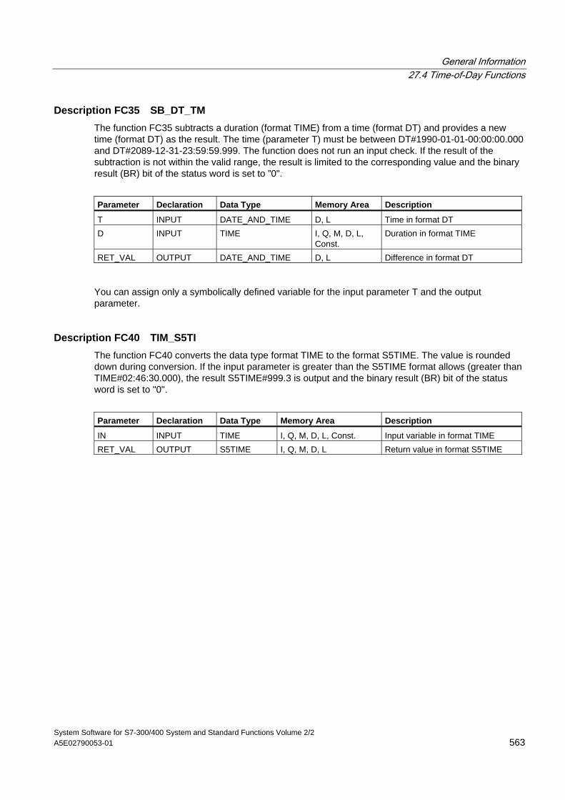
General Information 27.4 Time-of-Day Functions
System Software for S7-300/400 System and Standard Functions Volume 2/2 A5E02790053-01 563
Description FC35 SB_DT_TM The function FC35 subtracts a duration (format TIME) from a time (format DT) and provides a new time (format DT) as the result. The time (parameter T) must be between DT#1990-01-01-00:00:00.000 and DT#2089-12-31-23:59:59.999. The function does not run an input check. If the result of the subtraction is not within the valid range, the result is limited to the corresponding value and the binary result (BR) bit of the status word is set to ”0".
Parameter Declaration Data Type Memory Area Description
T INPUT DATE_AND_TIME D, L Time in format DT D INPUT TIME I, Q, M, D, L,
Const. Duration in format TIME
RET_VAL OUTPUT DATE_AND_TIME D, L Difference in format DT
You can assign only a symbolically defined variable for the input parameter T and the output parameter.
Description FC40 TIM_S5TI The function FC40 converts the data type format TIME to the format S5TIME. The value is rounded down during conversion. If the input parameter is greater than the S5TIME format allows (greater than TIME#02:46:30.000), the result S5TIME#999.3 is output and the binary result (BR) bit of the status word is set to "0".
Parameter Declaration Data Type Memory Area Description
IN INPUT TIME I, Q, M, D, L, Const. Input variable in format TIME RET_VAL OUTPUT S5TIME I, Q, M, D, L Return value in format S5TIME
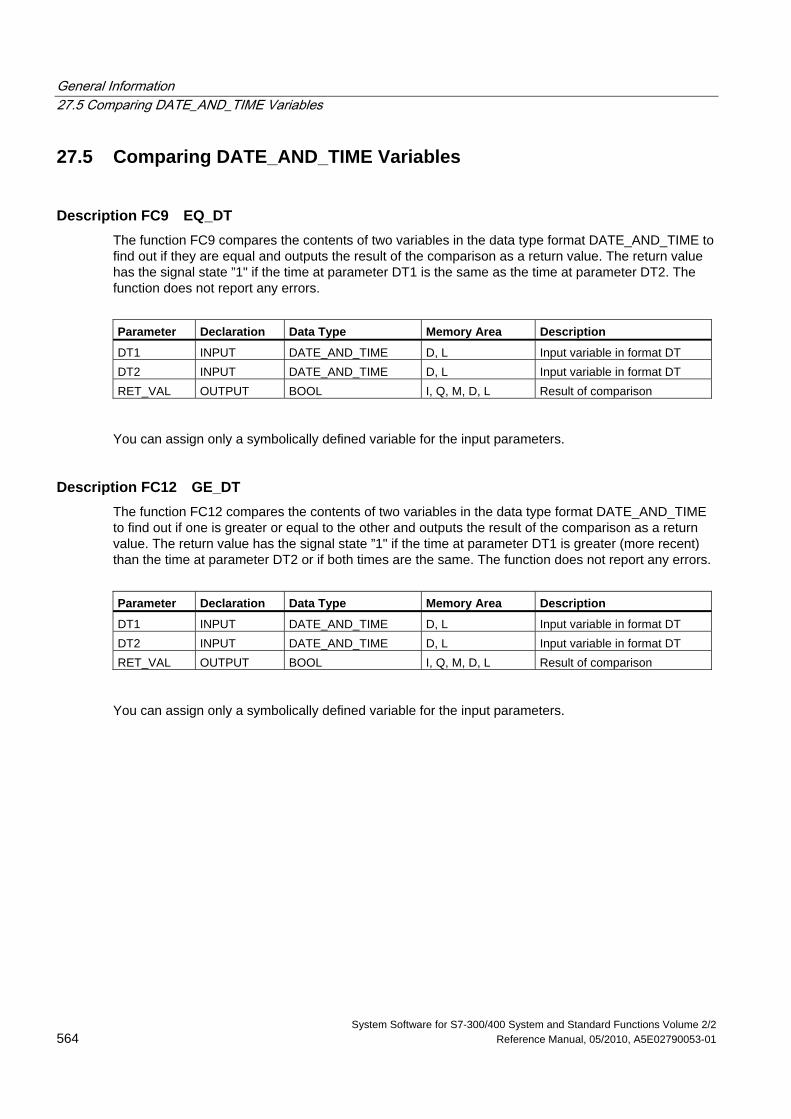
General Information 27.5 Comparing DATE_AND_TIME Variables
System Software for S7-300/400 System and Standard Functions Volume 2/2 564 Reference Manual, 05/2010, A5E02790053-01
27.5 Comparing DATE_AND_TIME Variables
Description FC9 EQ_DT The function FC9 compares the contents of two variables in the data type format DATE_AND_TIME to find out if they are equal and outputs the result of the comparison as a return value. The return value has the signal state ”1" if the time at parameter DT1 is the same as the time at parameter DT2. The function does not report any errors.
Parameter Declaration Data Type Memory Area Description
DT1 INPUT DATE_AND_TIME D, L Input variable in format DT DT2 INPUT DATE_AND_TIME D, L Input variable in format DT RET_VAL OUTPUT BOOL I, Q, M, D, L Result of comparison
You can assign only a symbolically defined variable for the input parameters.
Description FC12 GE_DT The function FC12 compares the contents of two variables in the data type format DATE_AND_TIME to find out if one is greater or equal to the other and outputs the result of the comparison as a return value. The return value has the signal state ”1" if the time at parameter DT1 is greater (more recent) than the time at parameter DT2 or if both times are the same. The function does not report any errors.
Parameter Declaration Data Type Memory Area Description
DT1 INPUT DATE_AND_TIME D, L Input variable in format DT DT2 INPUT DATE_AND_TIME D, L Input variable in format DT RET_VAL OUTPUT BOOL I, Q, M, D, L Result of comparison
You can assign only a symbolically defined variable for the input parameters.
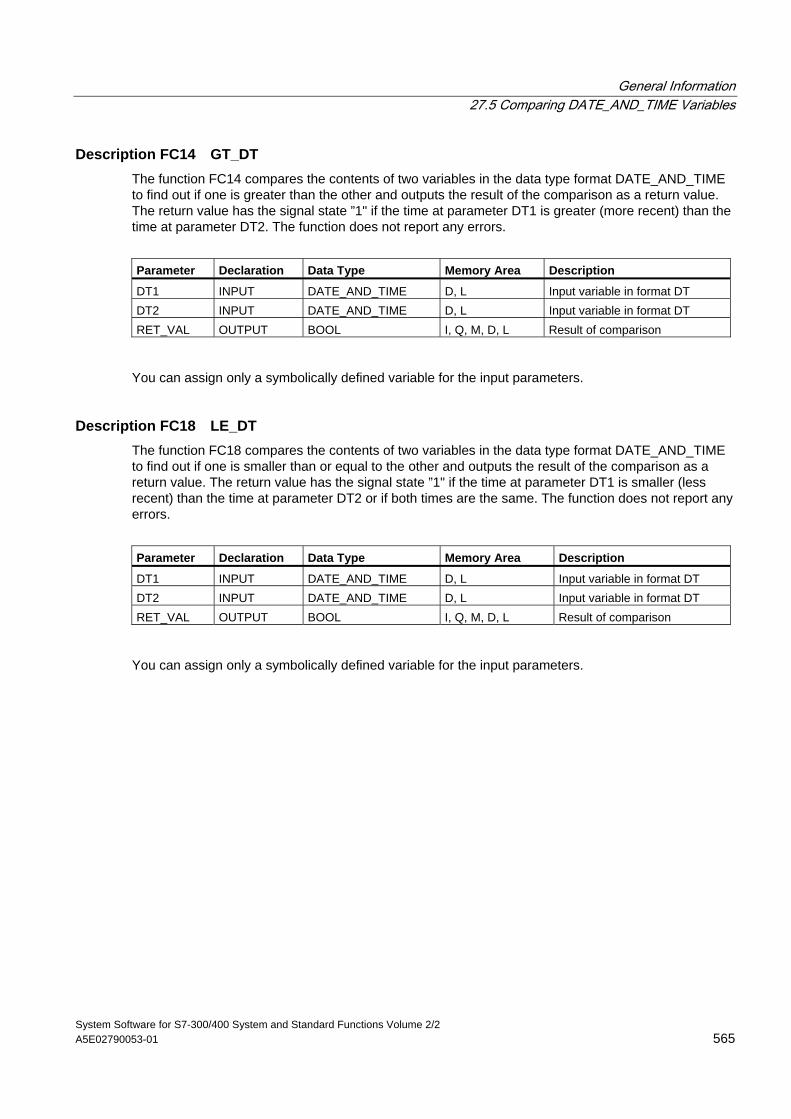
General Information 27.5 Comparing DATE_AND_TIME Variables
System Software for S7-300/400 System and Standard Functions Volume 2/2 A5E02790053-01 565
Description FC14 GT_DT The function FC14 compares the contents of two variables in the data type format DATE_AND_TIME to find out if one is greater than the other and outputs the result of the comparison as a return value. The return value has the signal state ”1" if the time at parameter DT1 is greater (more recent) than the time at parameter DT2. The function does not report any errors.
Parameter Declaration Data Type Memory Area Description
DT1 INPUT DATE_AND_TIME D, L Input variable in format DT DT2 INPUT DATE_AND_TIME D, L Input variable in format DT RET_VAL OUTPUT BOOL I, Q, M, D, L Result of comparison
You can assign only a symbolically defined variable for the input parameters.
Description FC18 LE_DT The function FC18 compares the contents of two variables in the data type format DATE_AND_TIME to find out if one is smaller than or equal to the other and outputs the result of the comparison as a return value. The return value has the signal state ”1" if the time at parameter DT1 is smaller (less recent) than the time at parameter DT2 or if both times are the same. The function does not report any errors.
Parameter Declaration Data Type Memory Area Description
DT1 INPUT DATE_AND_TIME D, L Input variable in format DT DT2 INPUT DATE_AND_TIME D, L Input variable in format DT RET_VAL OUTPUT BOOL I, Q, M, D, L Result of comparison
You can assign only a symbolically defined variable for the input parameters.
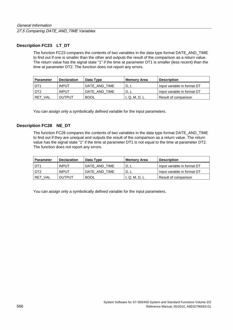
General Information 27.5 Comparing DATE_AND_TIME Variables
System Software for S7-300/400 System and Standard Functions Volume 2/2 566 Reference Manual, 05/2010, A5E02790053-01
Description FC23 LT_DT The function FC23 compares the contents of two variables in the data type format DATE_AND_TIME to find out if one is smaller than the other and outputs the result of the comparison as a return value. The return value has the signal state ”1" if the time at parameter DT1 is smaller (less recent) than the time at parameter DT2. The function does not report any errors.
Parameter Declaration Data Type Memory Area Description
DT1 INPUT DATE_AND_TIME D, L Input variable in format DT DT2 INPUT DATE_AND_TIME D, L Input variable in format DT RET_VAL OUTPUT BOOL I, Q, M, D, L Result of comparison
You can assign only a symbolically defined variable for the input parameters.
Description FC28 NE_DT The function FC28 compares the contents of two variables in the data type format DATE_AND_TIME to find out if they are unequal and outputs the result of the comparison as a return value. The return value has the signal state ”1" if the time at parameter DT1 is not equal to the time at parameter DT2. The function does not report any errors.
Parameter Declaration Data Type Memory Area Description
DT1 INPUT DATE_AND_TIME D, L Input variable in format DT DT2 INPUT DATE_AND_TIME D, L Input variable in format DT RET_VAL OUTPUT BOOL I, Q, M, D, L Result of comparison
You can assign only a symbolically defined variable for the input parameters.
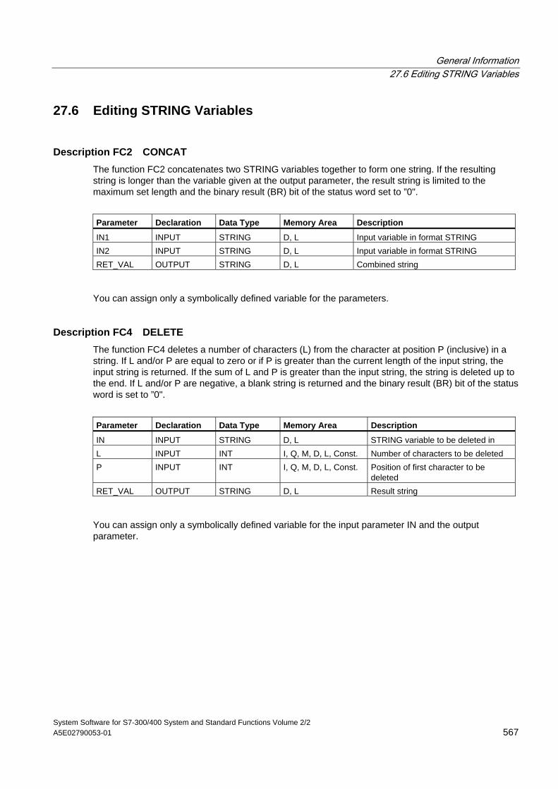
General Information 27.6 Editing STRING Variables
System Software for S7-300/400 System and Standard Functions Volume 2/2 A5E02790053-01 567
27.6 Editing STRING Variables
Description FC2 CONCAT The function FC2 concatenates two STRING variables together to form one string. If the resulting string is longer than the variable given at the output parameter, the result string is limited to the maximum set length and the binary result (BR) bit of the status word set to ”0".
Parameter Declaration Data Type Memory Area Description
IN1 INPUT STRING D, L Input variable in format STRING IN2 INPUT STRING D, L Input variable in format STRING RET_VAL OUTPUT STRING D, L Combined string
You can assign only a symbolically defined variable for the parameters.
Description FC4 DELETE The function FC4 deletes a number of characters (L) from the character at position P (inclusive) in a string. If L and/or P are equal to zero or if P is greater than the current length of the input string, the input string is returned. If the sum of L and P is greater than the input string, the string is deleted up to the end. If L and/or P are negative, a blank string is returned and the binary result (BR) bit of the status word is set to ”0".
Parameter Declaration Data Type Memory Area Description
IN INPUT STRING D, L STRING variable to be deleted in L INPUT INT I, Q, M, D, L, Const. Number of characters to be deleted P INPUT INT I, Q, M, D, L, Const. Position of first character to be
deleted RET_VAL OUTPUT STRING D, L Result string
You can assign only a symbolically defined variable for the input parameter IN and the output parameter.
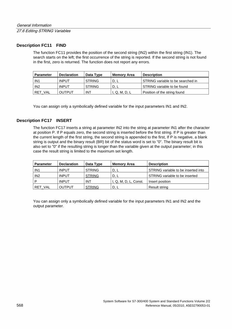
General Information 27.6 Editing STRING Variables
System Software for S7-300/400 System and Standard Functions Volume 2/2 568 Reference Manual, 05/2010, A5E02790053-01
Description FC11 FIND The function FC11 provides the position of the second string (IN2) within the first string (IN1). The search starts on the left; the first occurrence of the string is reported. If the second string is not found in the first, zero is returned. The function does not report any errors.
Parameter Declaration Data Type Memory Area Description
IN1 INPUT STRING D, L STRING variable to be searched in IN2 INPUT STRING D, L STRING variable to be found RET_VAL OUTPUT INT I, Q, M, D, L Position of the string found
You can assign only a symbolically defined variable for the input parameters IN1 and IN2.
Description FC17 INSERT The function FC17 inserts a string at parameter IN2 into the string at parameter IN1 after the character at position P. If P equals zero, the second string is inserted before the first string. If P is greater than the current length of the first string, the second string is appended to the first, If P is negative, a blank string is output and the binary result (BR) bit of the status word is set to ”0". The binary result bit is also set to ”0" if the resulting string is longer than the variable given at the output parameter; in this case the result string is limited to the maximum set length.
Parameter Declaration Data Type Memory Area Description
IN1 INPUT STRING D, L STRING variable to be inserted into IN2 INPUT STRING D, L STRING variable to be inserted P INPUT INT I, Q, M, D, L, Const. Insert position RET_VAL OUTPUT STRING D, L Result string
You can assign only a symbolically defined variable for the input parameters IN1 and IN2 and the output parameter.
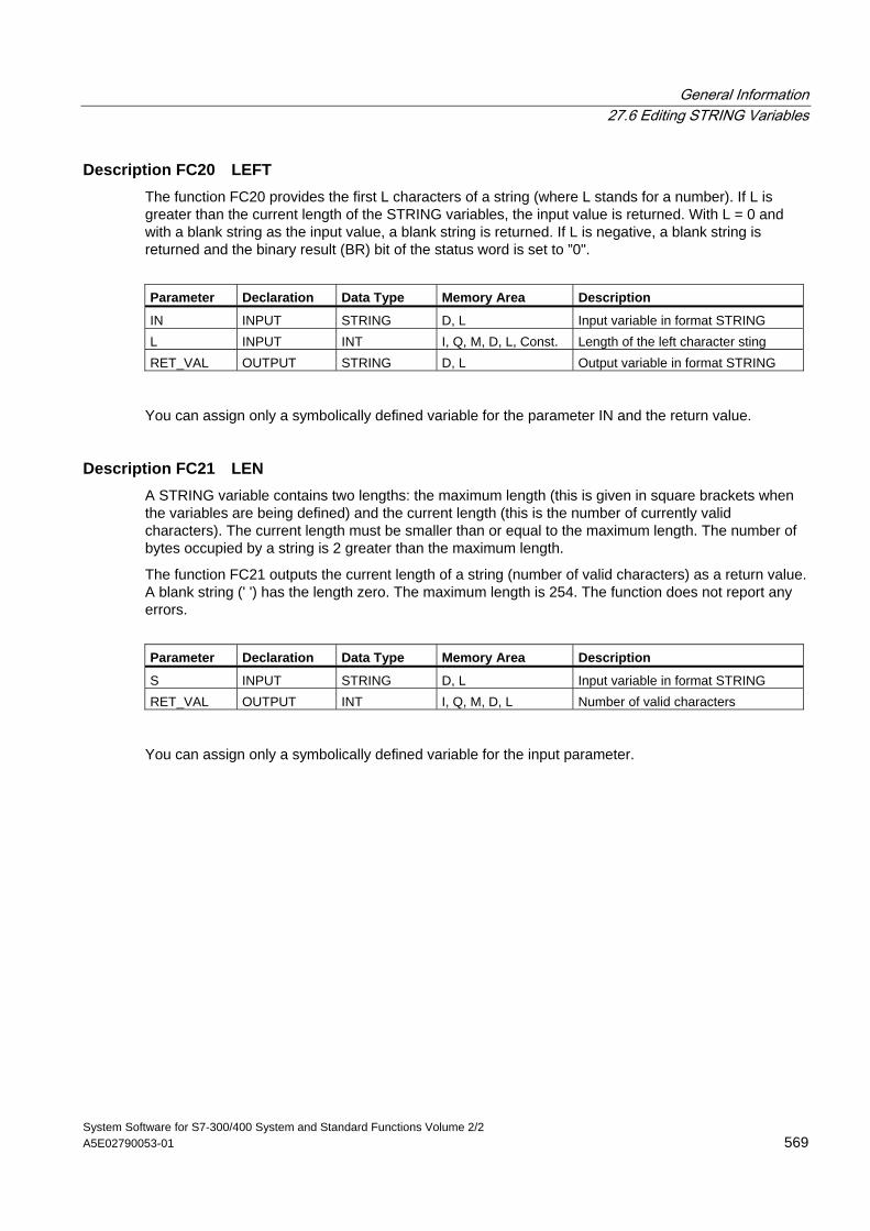
General Information 27.6 Editing STRING Variables
System Software for S7-300/400 System and Standard Functions Volume 2/2 A5E02790053-01 569
Description FC20 LEFT The function FC20 provides the first L characters of a string (where L stands for a number). If L is greater than the current length of the STRING variables, the input value is returned. With L = 0 and with a blank string as the input value, a blank string is returned. If L is negative, a blank string is returned and the binary result (BR) bit of the status word is set to ”0".
Parameter Declaration Data Type Memory Area Description
IN INPUT STRING D, L Input variable in format STRING L INPUT INT I, Q, M, D, L, Const. Length of the left character sting RET_VAL OUTPUT STRING D, L Output variable in format STRING
You can assign only a symbolically defined variable for the parameter IN and the return value.
Description FC21 LEN A STRING variable contains two lengths: the maximum length (this is given in square brackets when the variables are being defined) and the current length (this is the number of currently valid characters). The current length must be smaller than or equal to the maximum length. The number of bytes occupied by a string is 2 greater than the maximum length.
The function FC21 outputs the current length of a string (number of valid characters) as a return value. A blank string (' ') has the length zero. The maximum length is 254. The function does not report any errors.
Parameter Declaration Data Type Memory Area Description
S INPUT STRING D, L Input variable in format STRING RET_VAL OUTPUT INT I, Q, M, D, L Number of valid characters
You can assign only a symbolically defined variable for the input parameter.
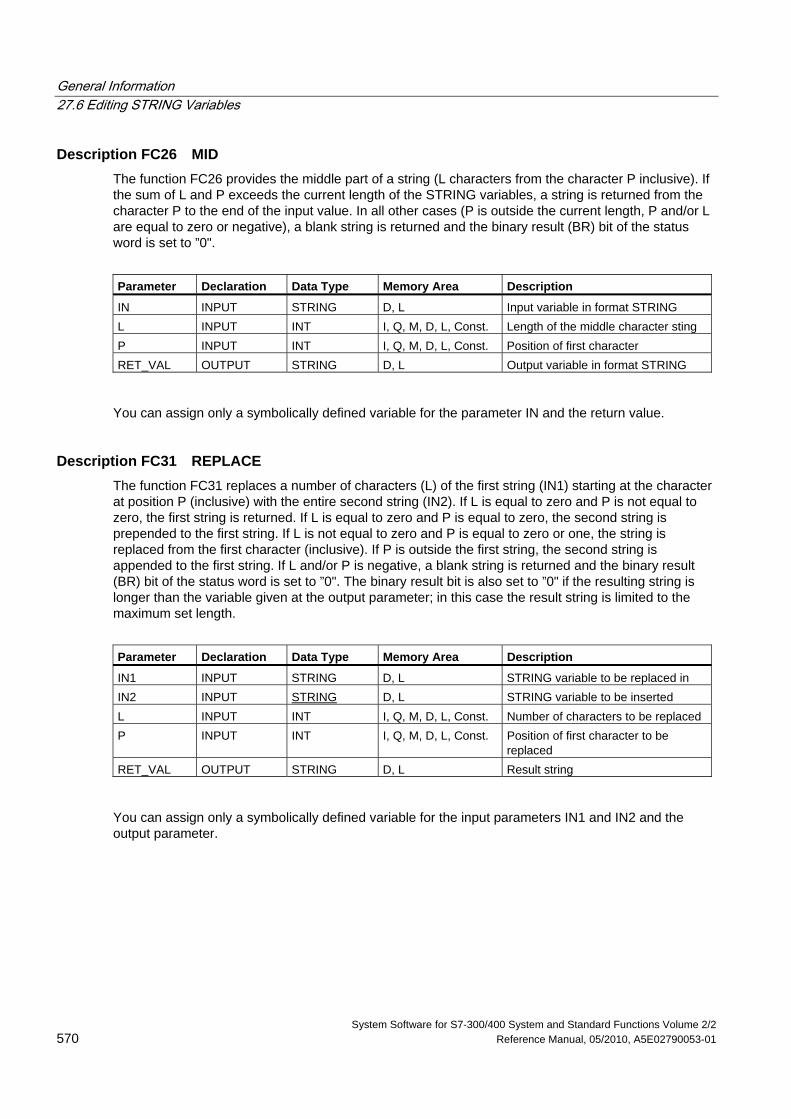
General Information 27.6 Editing STRING Variables
System Software for S7-300/400 System and Standard Functions Volume 2/2 570 Reference Manual, 05/2010, A5E02790053-01
Description FC26 MID The function FC26 provides the middle part of a string (L characters from the character P inclusive). If the sum of L and P exceeds the current length of the STRING variables, a string is returned from the character P to the end of the input value. In all other cases (P is outside the current length, P and/or L are equal to zero or negative), a blank string is returned and the binary result (BR) bit of the status word is set to ”0".
Parameter Declaration Data Type Memory Area Description
IN INPUT STRING D, L Input variable in format STRING L INPUT INT I, Q, M, D, L, Const. Length of the middle character sting P INPUT INT I, Q, M, D, L, Const. Position of first character RET_VAL OUTPUT STRING D, L Output variable in format STRING
You can assign only a symbolically defined variable for the parameter IN and the return value.
Description FC31 REPLACE The function FC31 replaces a number of characters (L) of the first string (IN1) starting at the character at position P (inclusive) with the entire second string (IN2). If L is equal to zero and P is not equal to zero, the first string is returned. If L is equal to zero and P is equal to zero, the second string is prepended to the first string. If L is not equal to zero and P is equal to zero or one, the string is replaced from the first character (inclusive). If P is outside the first string, the second string is appended to the first string. If L and/or P is negative, a blank string is returned and the binary result (BR) bit of the status word is set to ”0". The binary result bit is also set to ”0" if the resulting string is longer than the variable given at the output parameter; in this case the result string is limited to the maximum set length.
Parameter Declaration Data Type Memory Area Description
IN1 INPUT STRING D, L STRING variable to be replaced in IN2 INPUT STRING D, L STRING variable to be inserted L INPUT INT I, Q, M, D, L, Const. Number of characters to be replaced P INPUT INT I, Q, M, D, L, Const. Position of first character to be
replaced RET_VAL OUTPUT STRING D, L Result string
You can assign only a symbolically defined variable for the input parameters IN1 and IN2 and the output parameter.
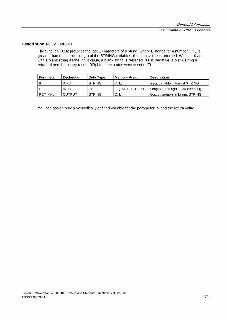
General Information 27.6 Editing STRING Variables
System Software for S7-300/400 System and Standard Functions Volume 2/2 A5E02790053-01 571
Description FC32 RIGHT The function FC32 provides the last L characters of a string (where L stands for a number). If L is greater than the current length of the STRING variables, the input value is returned. With L = 0 and with a blank string as the input value, a blank string is returned. If L is negative, a blank string is returned and the binary result (BR) bit of the status word is set to ”0".
Parameter Declaration Data Type Memory Area Description
IN INPUT STRING D, L, Input variable in format STRING L INPUT INT I, Q, M, D, L, Const. Length of the right character sting RET_VAL OUTPUT STRING D, L Output variable in format STRING
You can assign only a symbolically defined variable for the parameter IN and the return value.
General Information 27.7 Comparing STRING Variables
System Software for S7-300/400 System and Standard Functions Volume 2/2 572 Reference Manual, 05/2010, A5E02790053-01
27.7 Comparing STRING Variables
Description FC10 EQ_STRNG The function FC10 compares the contents of two variables in the data type format STRING to find out if they are equal and outputs the result of the comparison as a return value. The return value has the signal state ”1" if the string at parameter S1 is the same as the string at parameter S2.
The function does not report any errors.
Parameter Declaration Data Type Memory Area Description
S1 INPUT STRING D, L Input variable in format STRING S2 INPUT STRING D, L Input variable in format STRING RET_VAL OUTPUT BOOL I, Q, M, D, L Result of comparison
You can assign only a symbolically defined variable for the input parameters.
Description FC13 GE_STRNG The function FC13 compares the contents of two variables in the data type format STRING to find out if the first is greater than or equal to the other and outputs the result of the comparison as a return value. The return value has the signal state ”1" if the string at parameter S1 is greater than or equal to the string at parameter S2.
The characters are compared by their ASCII code (for example, 'a' is greater than 'A'), starting from the left. The first character to be different decides the result of the comparison. If the first characters are the same, the longer string is greater.
The function does not report any errors.
Parameter Declaration Data Type Memory Area Description
S1 INPUT STRING D, L Input variable in format STRING S2 INPUT STRING D, L Input variable in format STRING RET_VAL OUTPUT BOOL I, Q, M, D, L Result of comparison
You can assign only a symbolically defined variable for the input parameters.
General Information 27.7 Comparing STRING Variables
System Software for S7-300/400 System and Standard Functions Volume 2/2 A5E02790053-01 573
Description FC15 GT_STRNG The function FC15 compares the contents of two variables in the data type format STRING to find out if the first is greater than the other and outputs the result of the comparison as a return value. The return value has the signal state ”1" if the string at parameter S1 is greater than the string at parameter S2.
The characters are compared by their ASCII code (for example, 'a' is greater than 'A'), starting from the left. The first character to be different decides the result of the comparison. If the first characters are the same, the longer string is greater.
The function does not report any errors.
Parameter Declaration Data Type Memory Area Description
S1 INPUT STRING D, L Input variable in format STRING S2 INPUT STRING D, L Input variable in format STRING RET_VAL OUTPUT BOOL I, Q, M, D, L Result of comparison
You can assign only a symbolically defined variable for the input parameters.
FC19 LE_STRNG The function FC19 compares the contents of two variables in the data type format STRING to find out if the first is smaller than or equal to the other and outputs the result of the comparison as a return value. The return value has the signal state ”1" if the string at parameter S1 is smaller than or equal to the string at parameter S2.
The characters are compared by their ASCII code (for example, 'a' is smaller than 'A'), starting from the left. The first character to be different decides the result of the comparison. If the first characters are the same, the shorter string is smaller.
The function does not report any errors.
Parameter Declaration Data Type Memory Area Description
S1 INPUT STRING D, L Input variable in format STRING S2 INPUT STRING D, L Input variable in format STRING RET_VAL OUTPUT BOOL I, Q, M, D, L Result of comparison
You can assign only a symbolically defined variable for the input parameters.
General Information 27.7 Comparing STRING Variables
System Software for S7-300/400 System and Standard Functions Volume 2/2 574 Reference Manual, 05/2010, A5E02790053-01
Description FC24 LT_STRNG The function FC24 compares the contents of two variables in the data type format STRING to find out if the first is smaller than the other and outputs the result of the comparison as a return value. The return value has the signal state ”1" if the string at parameter S1 is smaller than the string at parameter S2.
The characters are compared by their ASCII code (for example, 'a' is smaller than 'A'), starting from the left. The first character to be different decides the result of the comparison. If the left part of the longer character string and the shorter character string are the same, the shorter string is smaller.
The function does not report any errors.
Parameter Declaration Data Type Memory Area Description
S1 INPUT STRING D, L Input variable in format STRING S2 INPUT STRING D, L Input variable in format STRING RET_VAL OUTPUT BOOL I, Q, M, D, L Result of comparison
You can assign only a symbolically defined variable for the input parameters.
Description FC29 NE_STRNG The function FC29 compares the contents of two variables in the data type format STRING and checks to see that they are not the same and outputs the result of the comparison as a return value. The return value has the signal state ”1" if the string at arameter S1 is not the same as the string at parameter S2.
The function does not report any errors.
Parameter Declaration Data Type Memory Area Description
S1 INPUT STRING D, L Input variable in format STRING S2 INPUT STRING D, L Input variable in format STRING RET_VAL OUTPUT BOOL I, Q, M, D, L Result of comparison
You can assign only a symbolically defined variable for the input parameters.
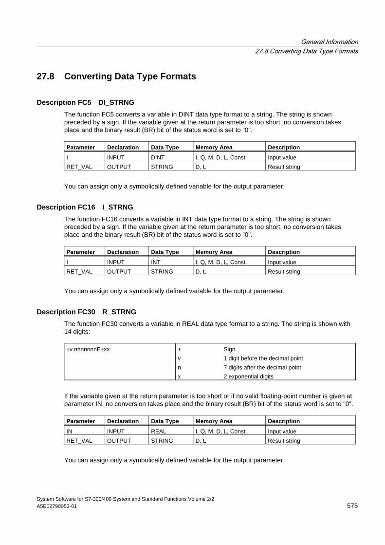
General Information 27.8 Converting Data Type Formats
System Software for S7-300/400 System and Standard Functions Volume 2/2 A5E02790053-01 575
27.8 Converting Data Type Formats
Description FC5 DI_STRNG The function FC5 converts a variable in DINT data type format to a string. The string is shown preceded by a sign. If the variable given at the return parameter is too short, no conversion takes place and the binary result (BR) bit of the status word is set to ”0". Parameter Declaration Data Type Memory Area Description
I INPUT DINT I, Q, M, D, L, Const. Input value RET_VAL OUTPUT STRING D, L Result string
You can assign only a symbolically defined variable for the output parameter.
Description FC16 I_STRNG The function FC16 converts a variable in INT data type format to a string. The string is shown preceded by a sign. If the variable given at the return parameter is too short, no conversion takes place and the binary result (BR) bit of the status word is set to ”0". Parameter Declaration Data Type Memory Area Description
I INPUT INT I, Q, M, D, L, Const. Input value RET_VAL OUTPUT STRING D, L Result string
You can assign only a symbolically defined variable for the output parameter.
Description FC30 R_STRNG The function FC30 converts a variable in REAL data type format to a string. The string is shown with 14 digits: ±v.nnnnnnnE±xx ± Sign
v 1 digit before the decimal point n 7 digits after the decimal point x 2 exponential digits
If the variable given at the return parameter is too short or if no valid floating-point number is given at parameter IN, no conversion takes place and the binary result (BR) bit of the status word is set to ”0". Parameter Declaration Data Type Memory Area Description
IN INPUT REAL I, Q, M, D, L, Const. Input value RET_VAL OUTPUT STRING D, L Result string
You can assign only a symbolically defined variable for the output parameter.
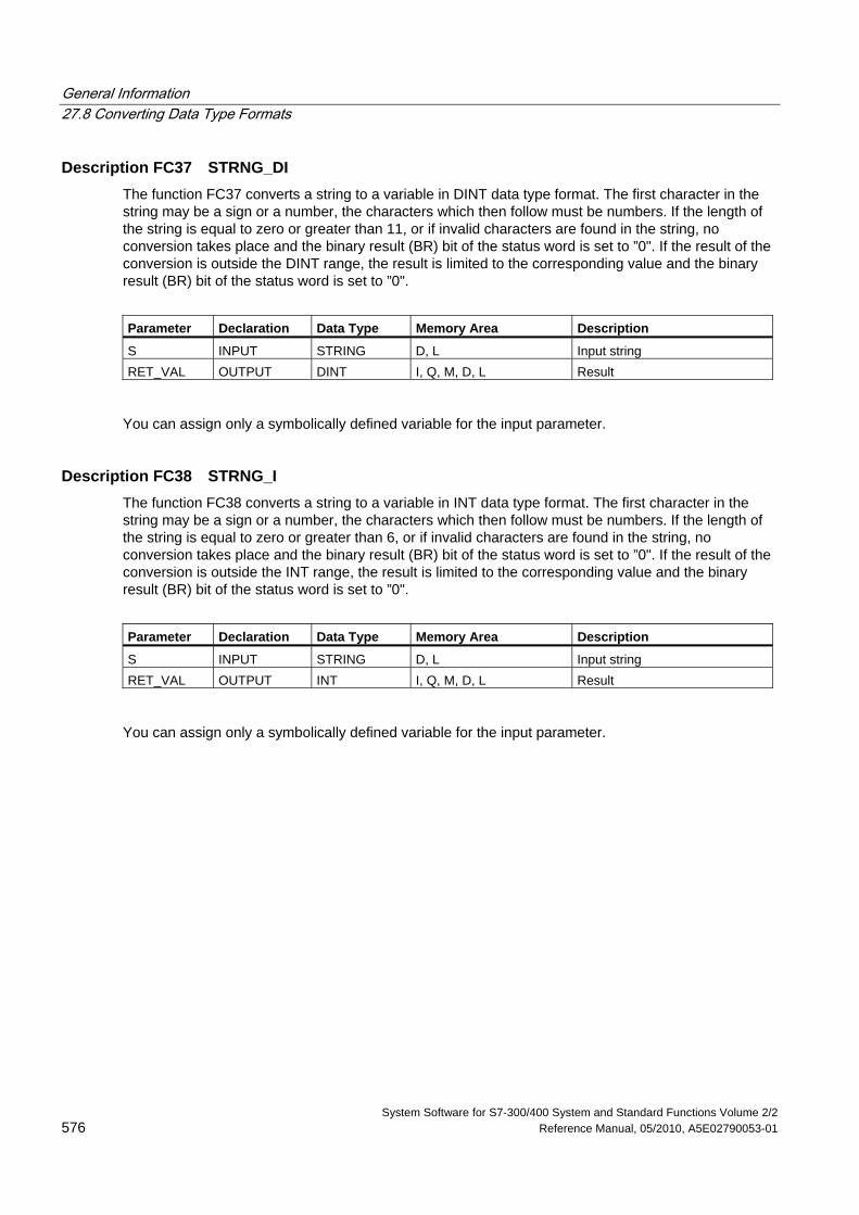
General Information 27.8 Converting Data Type Formats
System Software for S7-300/400 System and Standard Functions Volume 2/2 576 Reference Manual, 05/2010, A5E02790053-01
Description FC37 STRNG_DI The function FC37 converts a string to a variable in DINT data type format. The first character in the string may be a sign or a number, the characters which then follow must be numbers. If the length of the string is equal to zero or greater than 11, or if invalid characters are found in the string, no conversion takes place and the binary result (BR) bit of the status word is set to ”0". If the result of the conversion is outside the DINT range, the result is limited to the corresponding value and the binary result (BR) bit of the status word is set to ”0".
Parameter Declaration Data Type Memory Area Description
S INPUT STRING D, L Input string RET_VAL OUTPUT DINT I, Q, M, D, L Result
You can assign only a symbolically defined variable for the input parameter.
Description FC38 STRNG_I The function FC38 converts a string to a variable in INT data type format. The first character in the string may be a sign or a number, the characters which then follow must be numbers. If the length of the string is equal to zero or greater than 6, or if invalid characters are found in the string, no conversion takes place and the binary result (BR) bit of the status word is set to ”0". If the result of the conversion is outside the INT range, the result is limited to the corresponding value and the binary result (BR) bit of the status word is set to ”0".
Parameter Declaration Data Type Memory Area Description
S INPUT STRING D, L Input string RET_VAL OUTPUT INT I, Q, M, D, L Result
You can assign only a symbolically defined variable for the input parameter.
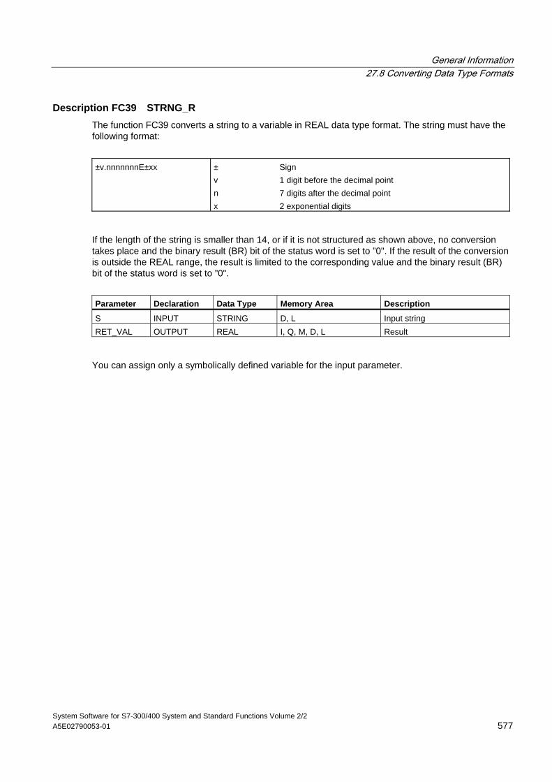
General Information 27.8 Converting Data Type Formats
System Software for S7-300/400 System and Standard Functions Volume 2/2 A5E02790053-01 577
Description FC39 STRNG_R The function FC39 converts a string to a variable in REAL data type format. The string must have the following format:
±v.nnnnnnnE±xx ± Sign
v 1 digit before the decimal point n 7 digits after the decimal point x 2 exponential digits
If the length of the string is smaller than 14, or if it is not structured as shown above, no conversion takes place and the binary result (BR) bit of the status word is set to ”0". If the result of the conversion is outside the REAL range, the result is limited to the corresponding value and the binary result (BR) bit of the status word is set to ”0".
Parameter Declaration Data Type Memory Area Description
S INPUT STRING D, L Input string RET_VAL OUTPUT REAL I, Q, M, D, L Result
You can assign only a symbolically defined variable for the input parameter.
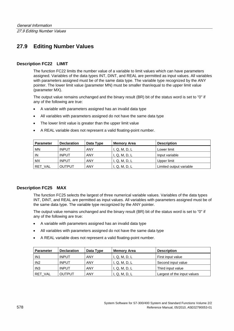
General Information 27.9 Editing Number Values
System Software for S7-300/400 System and Standard Functions Volume 2/2 578 Reference Manual, 05/2010, A5E02790053-01
27.9 Editing Number Values
Description FC22 LIMIT The function FC22 limits the number value of a variable to limit values which can have parameters assigned. Variables of the data types INT, DINT, and REAL are permitted as input values. All variables with parameters assigned must be of the same data type. The variable type recognized by the ANY pointer. The lower limit value (parameter MN) must be smaller than/equal to the upper limit value (parameter MX).
The output value remains unchanged and the binary result (BR) bit of the status word is set to ”0" if any of the following are true:
• A variable with parameters assigned has an invalid data type
• All variables with parameters assigned do not have the same data type
• The lower limit value is greater than the upper limit value
• A REAL variable does not represent a valid floating-point number.
Parameter Declaration Data Type Memory Area Description
MN INPUT ANY I, Q, M, D, L Lower limit IN INPUT ANY I, Q, M, D, L Input variable MX INPUT ANY I, Q, M, D, L Upper limit RET_VAL OUTPUT ANY I, Q, M, D, L Limited output variable
Description FC25 MAX The function FC25 selects the largest of three numerical variable values. Variables of the data types INT, DINT, and REAL are permitted as input values. All variables with parameters assigned must be of the same data type. The variable type recognized by the ANY pointer.
The output value remains unchanged and the binary result (BR) bit of the status word is set to ”0" if any of the following are true:
• A variable with parameters assigned has an invalid data type
• All variables with parameters assigned do not have the same data type
• A REAL variable does not represent a valid floating-point number.
Parameter Declaration Data Type Memory Area Description
IN1 INPUT ANY I, Q, M, D, L First input value IN2 INPUT ANY I, Q, M, D, L Second input value IN3 INPUT ANY I, Q, M, D, L Third input value RET_VAL OUTPUT ANY I, Q, M, D, L Largest of the input values
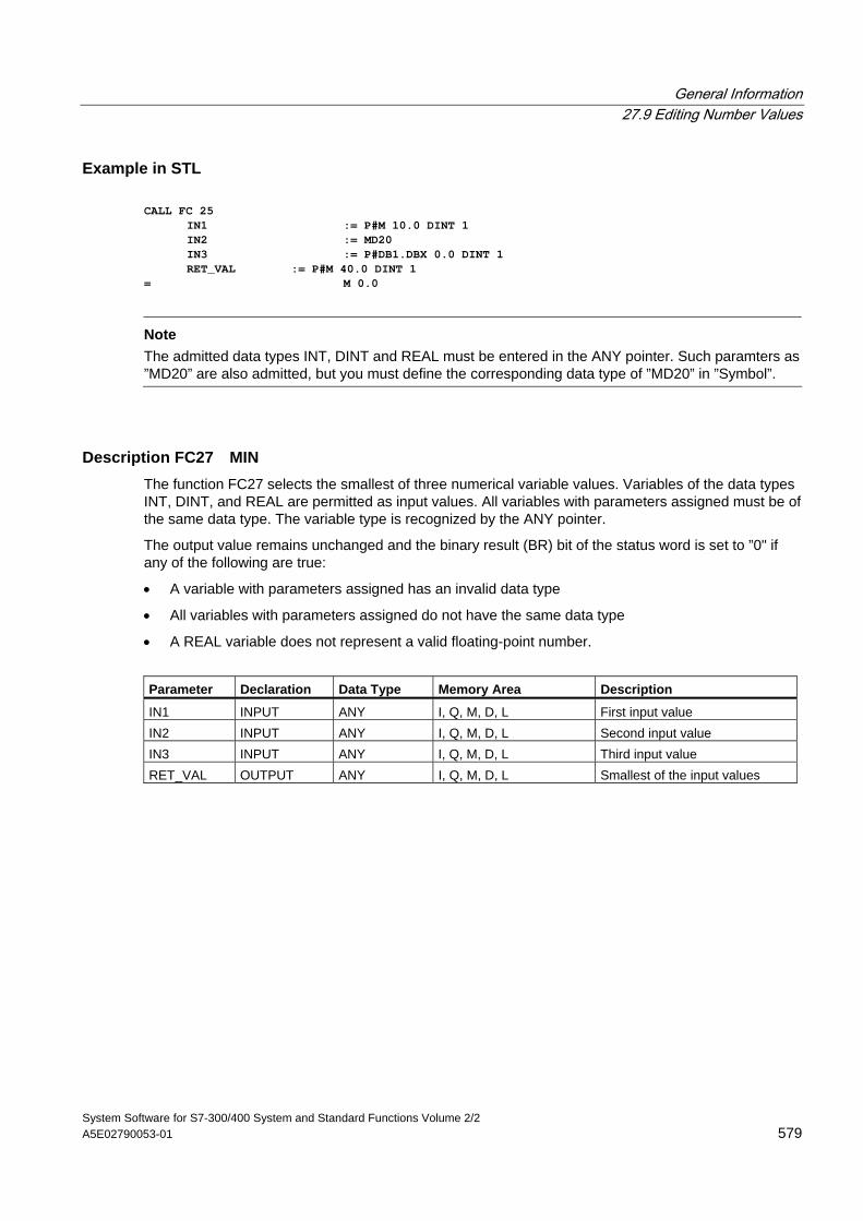
General Information 27.9 Editing Number Values
System Software for S7-300/400 System and Standard Functions Volume 2/2 A5E02790053-01 579
Example in STL CALL FC 25 IN1 := P#M 10.0 DINT 1 IN2 := MD20 IN3 := P#DB1.DBX 0.0 DINT 1 RET_VAL := P#M 40.0 DINT 1 = M 0.0
Note
The admitted data types INT, DINT and REAL must be entered in the ANY pointer. Such paramters as ”MD20” are also admitted, but you must define the corresponding data type of ”MD20” in ”Symbol”.
Description FC27 MIN The function FC27 selects the smallest of three numerical variable values. Variables of the data types INT, DINT, and REAL are permitted as input values. All variables with parameters assigned must be of the same data type. The variable type is recognized by the ANY pointer.
The output value remains unchanged and the binary result (BR) bit of the status word is set to ”0" if any of the following are true:
• A variable with parameters assigned has an invalid data type
• All variables with parameters assigned do not have the same data type
• A REAL variable does not represent a valid floating-point number.
Parameter Declaration Data Type Memory Area Description
IN1 INPUT ANY I, Q, M, D, L First input value IN2 INPUT ANY I, Q, M, D, L Second input value IN3 INPUT ANY I, Q, M, D, L Third input value RET_VAL OUTPUT ANY I, Q, M, D, L Smallest of the input values
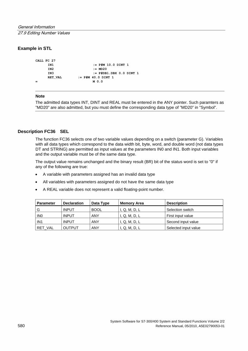
General Information 27.9 Editing Number Values
System Software for S7-300/400 System and Standard Functions Volume 2/2 580 Reference Manual, 05/2010, A5E02790053-01
Example in STL CALL FC 27 IN1 := P#M 10.0 DINT 1 IN2 := MD20 IN3 := P#DB1.DBX 0.0 DINT 1 RET_VAL := P#M 40.0 DINT 1 = M 0.0
Note
The admitted data types INT, DINT and REAL must be entered in the ANY pointer. Such paramters as ”MD20” are also admitted, but you must define the corresponding data type of ”MD20” in ”Symbol”.
Description FC36 SEL The function FC36 selects one of two variable values depending on a switch (parameter G). Variables with all data types which correspond to the data width bit, byte, word, and double word (not data types DT and STRING) are permitted as input values at the parameters IN0 and IN1. Both input variables and the output variable must be of the same data type.
The output value remains unchanged and the binary result (BR) bit of the status word is set to ”0" if any of the following are true:
• A variable with parameters assigned has an invalid data type
• All variables with parameters assigned do not have the same data type
• A REAL variable does not represent a valid floating-point number.
Parameter Declaration Data Type Memory Area Description
G INPUT BOOL I, Q, M, D, L Selection switch IN0 INPUT ANY I, Q, M, D, L First input value IN1 INPUT ANY I, Q, M, D, L Second input value RET_VAL OUTPUT ANY I, Q, M, D, L Selected input value
System Software for S7-300/400 System and Standard Functions Volume 2/2 Reference Manual, 05/2010, A5E02790053-01 581
28 SFBs for Integrated Control
28.1 Continuous Control with SFB 41/FB 41 "CONT_C"
Introduction SFB/FB "CONT_C" (continuous controller) is used on SIMATIC S7 programmable logic controllers to control technical processes with continuous input and output variables. During parameter assignment, you can activate or deactivate sub-functions of the PID controller to adapt the controller to the process. You can assign this easily by using the parameter assignment tool (Menu path: Start > Simatic > Step7 > Assign PID Control parameters). The online electronic manual is found under Start > Simatic > Step7 > Assign PID Control English.
Application You can use the controller as a PID fixed setpoint controller or in multi-loop controls as a cascade, blending or ratio controller. The functions of the controller are based on the PID control algorithm of the sampling controller with an analog signal, if necessary extended by including a pulse generator stage to generate pulse duration modulated output signals for two or three step controllers with proportional actuators.
Note
The calculation of the values in the control blocks is only correct if the block is called at regular intervals. For this reason, you should call the control blocks in a cyclic interrupt OB (OB30 to OB38). Enter the sampling time in the CYCLE parameter.
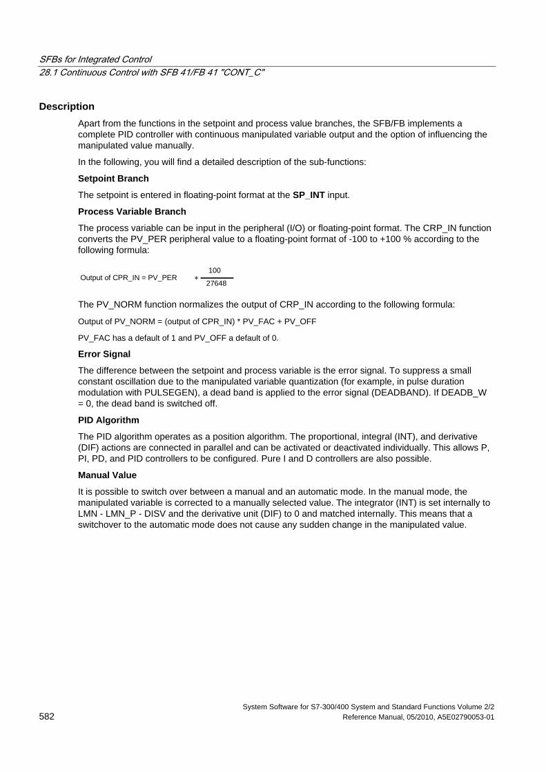
SFBs for Integrated Control 28.1 Continuous Control with SFB 41/FB 41 "CONT_C"
System Software for S7-300/400 System and Standard Functions Volume 2/2 582 Reference Manual, 05/2010, A5E02790053-01
Description Apart from the functions in the setpoint and process value branches, the SFB/FB implements a complete PID controller with continuous manipulated variable output and the option of influencing the manipulated value manually.
In the following, you will find a detailed description of the sub-functions:
Setpoint Branch
The setpoint is entered in floating-point format at the SP_INT input.
Process Variable Branch
The process variable can be input in the peripheral (I/O) or floating-point format. The CRP_IN function converts the PV_PER peripheral value to a floating-point format of -100 to +100 % according to the following formula:
Output of CPR_IN = PV_PER ∗100
27648
The PV_NORM function normalizes the output of CRP_IN according to the following formula:
Output of PV_NORM = (output of CPR_IN) * PV_FAC + PV_OFF
PV_FAC has a default of 1 and PV_OFF a default of 0.
Error Signal
The difference between the setpoint and process variable is the error signal. To suppress a small constant oscillation due to the manipulated variable quantization (for example, in pulse duration modulation with PULSEGEN), a dead band is applied to the error signal (DEADBAND). If DEADB_W = 0, the dead band is switched off.
PID Algorithm
The PID algorithm operates as a position algorithm. The proportional, integral (INT), and derivative (DIF) actions are connected in parallel and can be activated or deactivated individually. This allows P, PI, PD, and PID controllers to be configured. Pure I and D controllers are also possible.
Manual Value
It is possible to switch over between a manual and an automatic mode. In the manual mode, the manipulated variable is corrected to a manually selected value. The integrator (INT) is set internally to LMN - LMN_P - DISV and the derivative unit (DIF) to 0 and matched internally. This means that a switchover to the automatic mode does not cause any sudden change in the manipulated value.
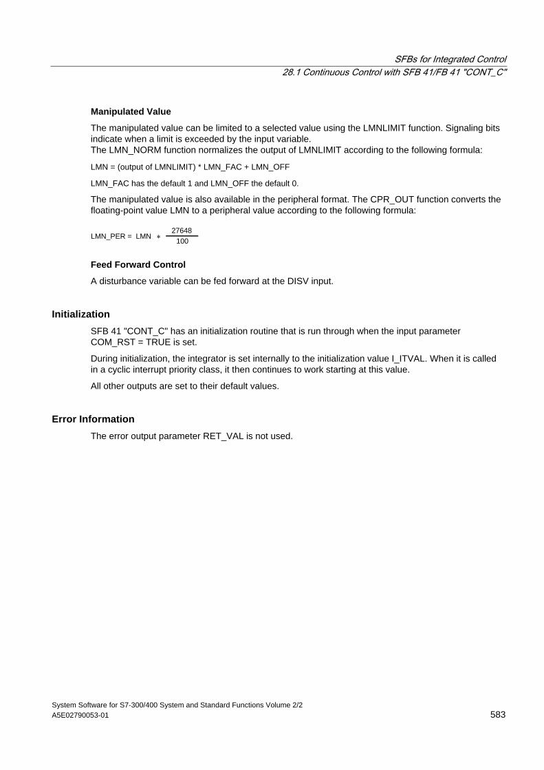
SFBs for Integrated Control 28.1 Continuous Control with SFB 41/FB 41 "CONT_C"
System Software for S7-300/400 System and Standard Functions Volume 2/2 A5E02790053-01 583
Manipulated Value
The manipulated value can be limited to a selected value using the LMNLIMIT function. Signaling bits indicate when a limit is exceeded by the input variable. The LMN_NORM function normalizes the output of LMNLIMIT according to the following formula:
LMN = (output of LMNLIMIT) * LMN_FAC + LMN_OFF
LMN_FAC has the default 1 and LMN_OFF the default 0.
The manipulated value is also available in the peripheral format. The CPR_OUT function converts the floating-point value LMN to a peripheral value according to the following formula:
LMN_PER = LMN ∗ 10027648
Feed Forward Control
A disturbance variable can be fed forward at the DISV input.
Initialization SFB 41 "CONT_C" has an initialization routine that is run through when the input parameter COM_RST = TRUE is set.
During initialization, the integrator is set internally to the initialization value I_ITVAL. When it is called in a cyclic interrupt priority class, it then continues to work starting at this value.
All other outputs are set to their default values.
Error Information The error output parameter RET_VAL is not used.
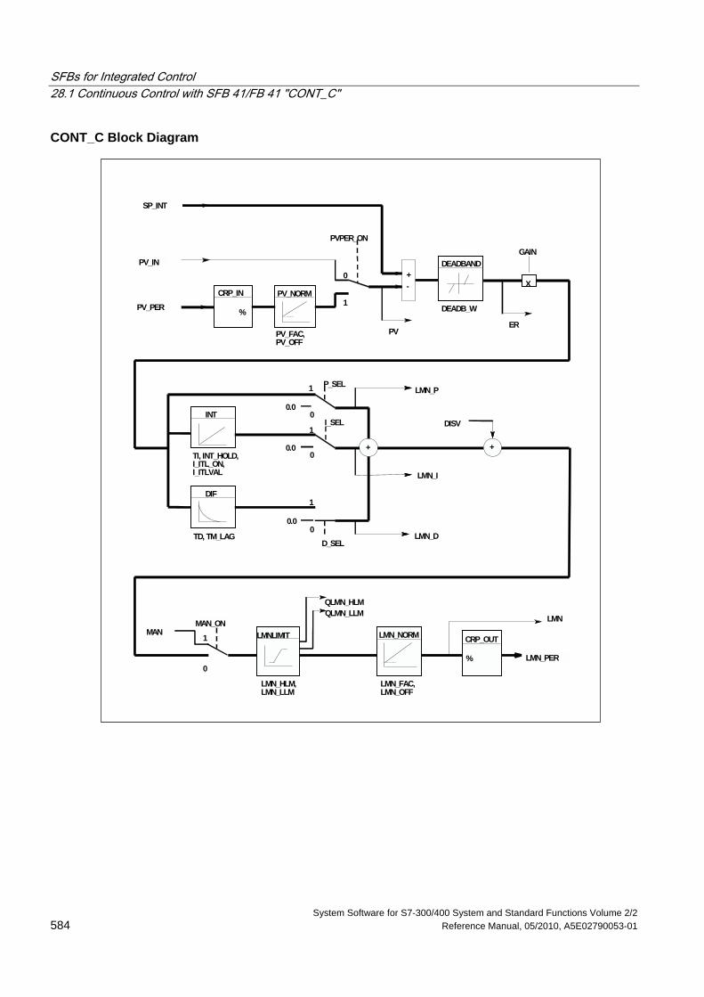
SFBs for Integrated Control 28.1 Continuous Control with SFB 41/FB 41 "CONT_C"
System Software for S7-300/400 System and Standard Functions Volume 2/2 584 Reference Manual, 05/2010, A5E02790053-01
CONT_C Block Diagram
PV_PER
SP_INT
CRP_IN
%
PV_NORM
DEADBANDPV_IN
PV_FAC,PV_OFF
PVPER_ON
-+
PV
DEADB_W
X
GAIN
ER
0
1
INT
DIF
+ +TI, INT_HOLD,I_ITL_ON,I_ITLVAL
TD, TM_LAG
P_SELLMN_P
I_SEL DISV
LMN_I
LMN_DD_SEL
0
1
0
1
0
1
0
1 LMNLIMIT
QLMN_HLMQLMN_LLM LMN
LMN_PER
CRP_OUT
%
LMN_NORMMANMAN_ON
LMN_HLM,LMN_LLM
LMN_FAC,LMN_OFF
0.0
0.0
0.0
SFBs for Integrated Control 28.1 Continuous Control with SFB 41/FB 41 "CONT_C"
System Software for S7-300/400 System and Standard Functions Volume 2/2 A5E02790053-01 585
Input Parameters The following table contains the description of the input parameters for SFB 41/FB 41 "CONT_C."
Parameter Data Type Range of Values Default Description
COM_RST BOOL FALSE COMPLETE RESTART The block has an initialization routine that is processed when the input COM_RST is set.
MAN_ON BOOL TRUE MANUAL VALUE ON If the input "manual value on" is set, the control loop is interrupted. A manual value is set as the manipulated value.
PVPER_ON BOOL FALSE PROCESS VARIABLE PERIPHERAL ON If the process variable is read from the I/Os, the input PV_PER must be connected to the I/Os and the input "process variable peripheral on" must be set.
P_SEL BOOL TRUE PROPORTIONAL ACTION ON The PID actions can be activated or deactivated individually in the PID algorithm. The P action is on when the input "proportional action on" is set.
I_SEL BOOL TRUE INTEGRAL ACTION ON The PID actions can be activated or deactivated individually in the PID algorithm. The I action is on when the input "integral action on" is set.
INT_HOLD BOOL FALSE INTEGRAL ACTION HOLD The output of the integrator can be "frozen" by setting the input "integral action hold."
I_ITL_ON BOOL FALSE INITIALIZATION OF THE INTEGRAL ACTION ON The output of the integrator can be connected to the input I_ITL_VAL by setting the input "initialization of the integral action on."
D_SEL BOOL FALSE DERIVATIVE ACTION ON The PID actions can be activated or deactivated individually in the PID algorithm. The D action is on when the input "derivative action on" is set.
CYCLE TIME >= 1 ms T#1s SAMPLING TIME The time between the block calls must be constant. The "sampling time" input specifies the time between block calls.
SP_INT REAL -100.0 to +100.0 (%) or phys. value 1)
0.0 INTERNAL SETPOINT The "internal setpoint" input is used to specify a setpoint.
PV_IN REAL -100.0 to +100.0 (%) or phys. Value 1)
0.0 PROCESS VARIABLE IN An initialization value can be set at the "process variable in" input or an external process variable in floating point format can be connected.
SFBs for Integrated Control 28.1 Continuous Control with SFB 41/FB 41 "CONT_C"
System Software for S7-300/400 System and Standard Functions Volume 2/2 586 Reference Manual, 05/2010, A5E02790053-01
Parameter Data Type Range of Values Default Description
PV_PER WORD W#16#0000
PROCESS VARIABLE PERIPHERAL The process variable in the I/O format is connected to the controller at the "process variable peripheral" input.
MAN REAL -100.0 to +100.0 (%) or phys. Value 2)
0.0 MANUAL VALUE The "manual value" input is used to set a manual value using the operator interface functions.
GAIN REAL 2.0 PROPORTIONAL GAIN The "proportional value" input specifies the controller gain.
TI TIME >= CYCLE T#20s RESET TIME The "reset time" input determines the time response of the integrator.
TD TIME >= CYCLE T#10s DERIVATIVE TIME The "derivative time" input determines the time response of the derivative unit.
TM_LAG TIME >= CYCLE/2 T#2s TIME LAG OF THE DERIVATIVE ACTION The algorithm of the D action includes a time lag that can be assigned at the "time lag of the derivative action" input.
DEADB_W REAL >= 0.0 (%) or phys. Value 1)
0.0 DEAD BAND WIDTH A dead band is applied to the error. The "dead band width" input determines the size of the dead band.
LMN_HLM REAL LMN_LLM ...100.0 (%)or phys. Value 2)
100.0 MANIPULATED VALUE HIGH LIMIT The manipulated value is always limited by an upper and lower limit. The "manipulated value high limit" input specifies the upper limit.
LMN_LLM REAL -100.0... LMN_HLM (%)or phys. Value 2)
0.0 MANIPULATED VALUE LOW LIMIT The manipulated value is always limited by an upper and lower limit. The "manipulated value low limit" input specifies the lower limit.
PV_FAC REAL 1.0 PROCESS VARIABLE FACTOR The "process variable factor" input is multiplied by the process variable. The input is used to adapt the process variable range.
PV_OFF REAL 0.0 PROCESS VARIABLE OFFSET The "process variable offset" input is added to the process variable. The input is used to adapt the process variable range.
LMN_FAC REAL 1.0 MANIPULATED VALUE FACTOR The "manipulated value factor" input is multiplied by the manipulated value. The input is used to adapt the manipulated value range.
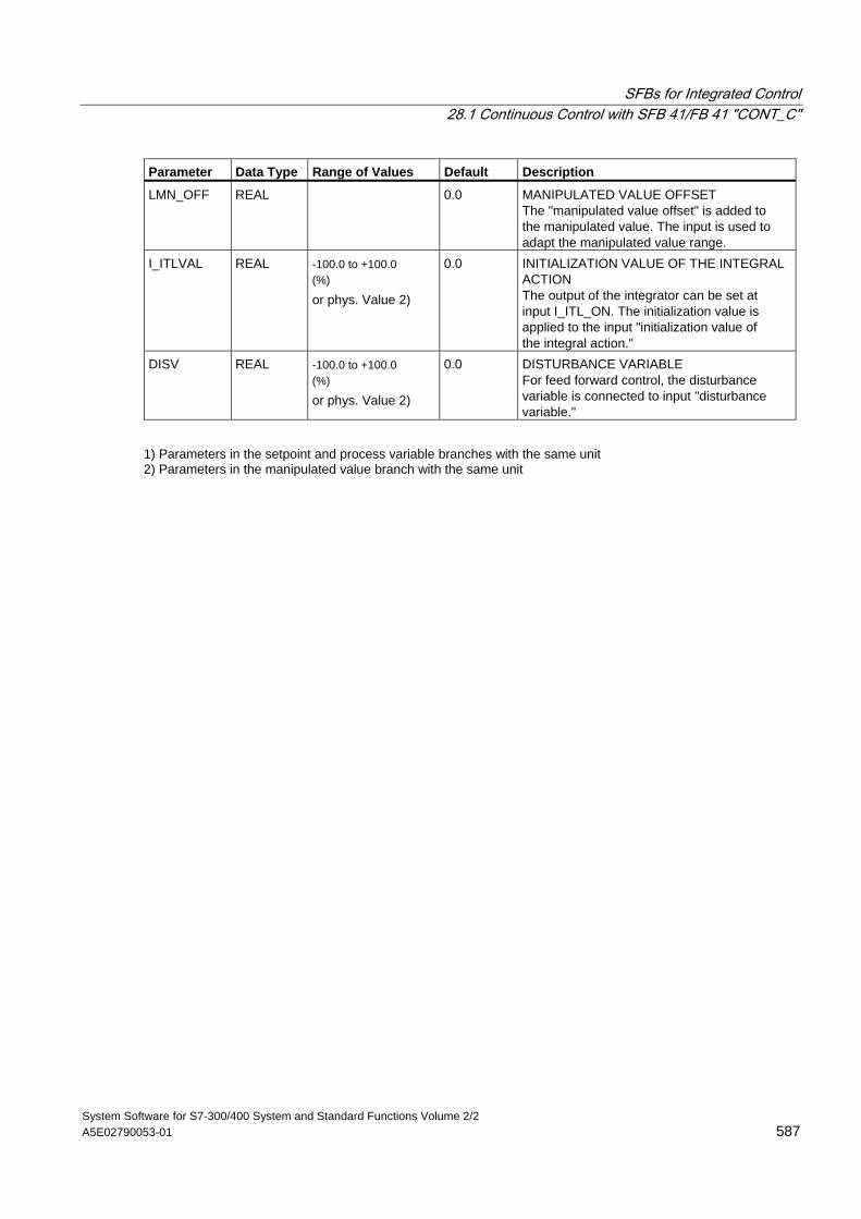
SFBs for Integrated Control 28.1 Continuous Control with SFB 41/FB 41 "CONT_C"
System Software for S7-300/400 System and Standard Functions Volume 2/2 A5E02790053-01 587
Parameter Data Type Range of Values Default Description
LMN_OFF REAL 0.0 MANIPULATED VALUE OFFSET The "manipulated value offset" is added to the manipulated value. The input is used to adapt the manipulated value range.
I_ITLVAL REAL -100.0 to +100.0 (%) or phys. Value 2)
0.0 INITIALIZATION VALUE OF THE INTEGRAL ACTION The output of the integrator can be set at input I_ITL_ON. The initialization value is applied to the input "initialization value of the integral action."
DISV REAL -100.0 to +100.0 (%) or phys. Value 2)
0.0 DISTURBANCE VARIABLE For feed forward control, the disturbance variable is connected to input "disturbance variable."
1) Parameters in the setpoint and process variable branches with the same unit 2) Parameters in the manipulated value branch with the same unit
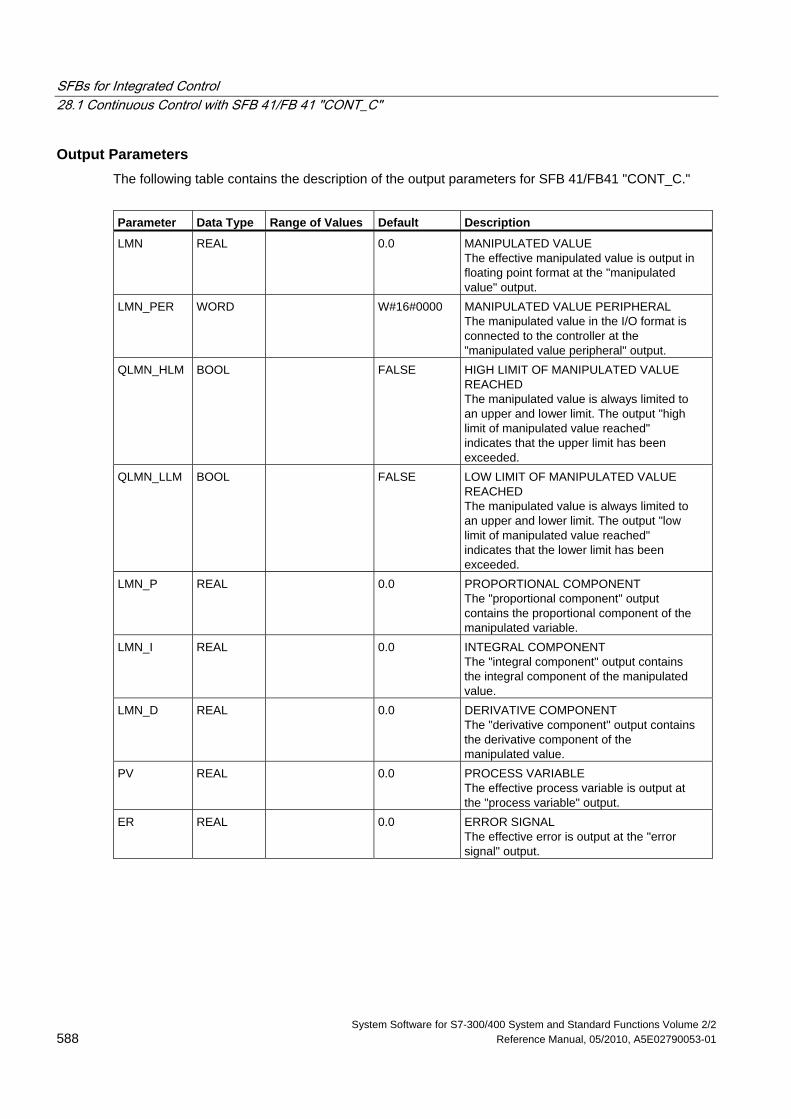
SFBs for Integrated Control 28.1 Continuous Control with SFB 41/FB 41 "CONT_C"
System Software for S7-300/400 System and Standard Functions Volume 2/2 588 Reference Manual, 05/2010, A5E02790053-01
Output Parameters The following table contains the description of the output parameters for SFB 41/FB41 "CONT_C."
Parameter Data Type Range of Values Default Description
LMN REAL 0.0 MANIPULATED VALUE The effective manipulated value is output in floating point format at the "manipulated value" output.
LMN_PER WORD W#16#0000 MANIPULATED VALUE PERIPHERAL The manipulated value in the I/O format is connected to the controller at the "manipulated value peripheral" output.
QLMN_HLM BOOL FALSE HIGH LIMIT OF MANIPULATED VALUE REACHED The manipulated value is always limited to an upper and lower limit. The output "high limit of manipulated value reached" indicates that the upper limit has been exceeded.
QLMN_LLM BOOL FALSE LOW LIMIT OF MANIPULATED VALUE REACHED The manipulated value is always limited to an upper and lower limit. The output "low limit of manipulated value reached" indicates that the lower limit has been exceeded.
LMN_P REAL 0.0 PROPORTIONAL COMPONENT The "proportional component" output contains the proportional component of the manipulated variable.
LMN_I REAL 0.0 INTEGRAL COMPONENT The "integral component" output contains the integral component of the manipulated value.
LMN_D REAL 0.0 DERIVATIVE COMPONENT The "derivative component" output contains the derivative component of the manipulated value.
PV REAL 0.0 PROCESS VARIABLE The effective process variable is output at the "process variable" output.
ER REAL 0.0 ERROR SIGNAL The effective error is output at the "error signal" output.
SFBs for Integrated Control 28.2 Step Control with SFB 42/FB 42 "CONT_S"
System Software for S7-300/400 System and Standard Functions Volume 2/2 A5E02790053-01 589
28.2 Step Control with SFB 42/FB 42 "CONT_S"
Introduction SFB/FB "CONT_S" (step controller) is used on SIMATIC S7 programmable logic controllers to control technical processes with digital manipulated value output signals for integrating actuators. During parameter assignment, you can activate or deactivate sub-functions of the PI step controller to adapt the controller to the process. You can easily do this by using the parameter assignment tool (Menu path: Start > Simatic > Step7 > Assign PID Control parameters). The online electronic manual is found under Start > Simatic > Step7 > Assign PID Control English.
Application You can use the controller as a PI fixed setpoint controller or in secondary control loops in cascade, blending or ratio controllers, however not as the primary controller. The functions of the controller are based on the PI control algorithm of the sampling controller supplemented by the functions for generating the binary output signal from the analog actuating signal.
The following applies starting with FB V1.5 or V1.1.0 of CPU 314 IFM:
With TI = T#0ms, the integral component of the controller can be disabled, thus allowing the block to be used as a proportional controller.
Since the controller works without any position feedback signal, the internally calculated manipulated variable will not exactly match the signal control element position. An adjustment is made if the manipulated variable (ER * GAIN) is negative. The controller then sets the output QLMNDN (manipulated value signal low) until LMNR_LS (lower limit of the position feedback signal) is set.
The controller can also be used as a secondary actuator in a controller cascade. The setpoint input SP_INT is used to assign the control element position. In this case the actual value input and the parameter TI (integration time) must be set to zero. An application example is temperature regulation by means of heat output control using pulse-pause control and cooling capacity control by means of a valve. In this case, to close the valve completely, the manipulated variable (ER * GAIN) should have a negative setting.
Note
The calculation of the values in the control blocks is only correct if the block is called at regular intervals. For this reason, you should call the control blocks in a cyclic interrupt OB (OB30 to OB38). Enter the sampling time in the CYCLE parameter.
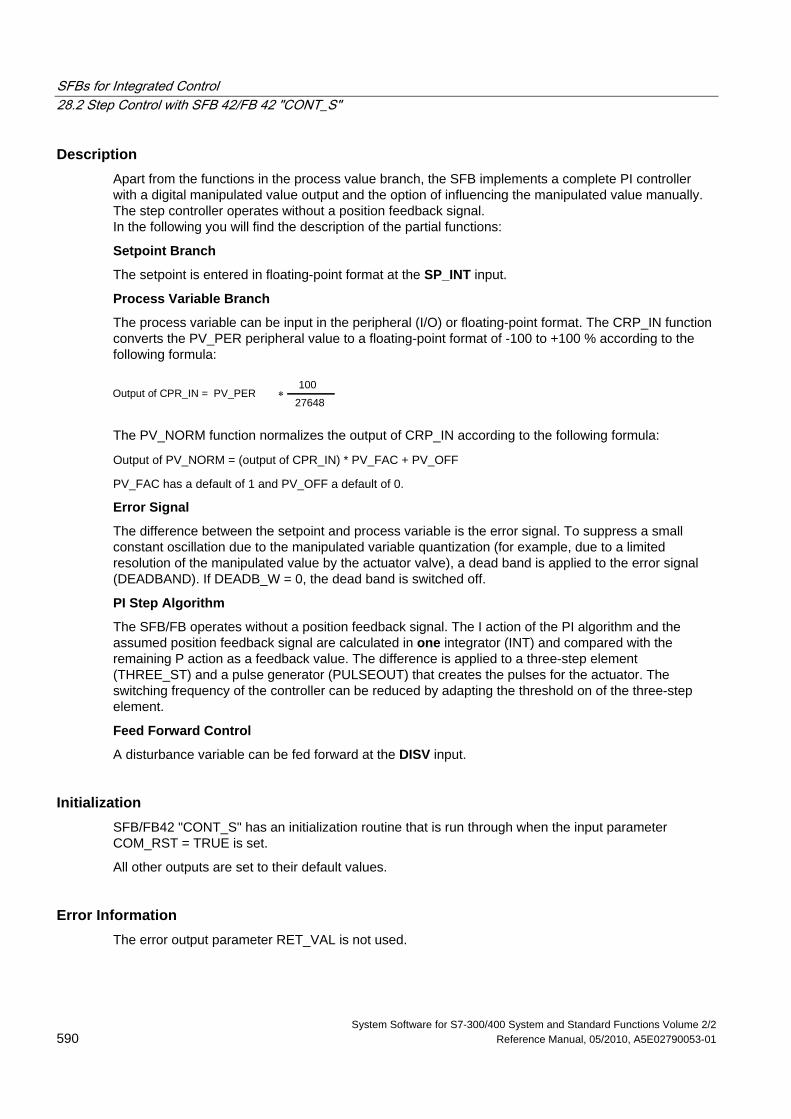
SFBs for Integrated Control 28.2 Step Control with SFB 42/FB 42 "CONT_S"
System Software for S7-300/400 System and Standard Functions Volume 2/2 590 Reference Manual, 05/2010, A5E02790053-01
Description Apart from the functions in the process value branch, the SFB implements a complete PI controller with a digital manipulated value output and the option of influencing the manipulated value manually. The step controller operates without a position feedback signal. In the following you will find the description of the partial functions:
Setpoint Branch
The setpoint is entered in floating-point format at the SP_INT input.
Process Variable Branch
The process variable can be input in the peripheral (I/O) or floating-point format. The CRP_IN function converts the PV_PER peripheral value to a floating-point format of -100 to +100 % according to the following formula:
Output of CPR_IN = PV_PER ∗100
27648
The PV_NORM function normalizes the output of CRP_IN according to the following formula:
Output of PV_NORM = (output of CPR_IN) * PV_FAC + PV_OFF
PV_FAC has a default of 1 and PV_OFF a default of 0.
Error Signal
The difference between the setpoint and process variable is the error signal. To suppress a small constant oscillation due to the manipulated variable quantization (for example, due to a limited resolution of the manipulated value by the actuator valve), a dead band is applied to the error signal (DEADBAND). If DEADB_W = 0, the dead band is switched off.
PI Step Algorithm
The SFB/FB operates without a position feedback signal. The I action of the PI algorithm and the assumed position feedback signal are calculated in one integrator (INT) and compared with the remaining P action as a feedback value. The difference is applied to a three-step element (THREE_ST) and a pulse generator (PULSEOUT) that creates the pulses for the actuator. The switching frequency of the controller can be reduced by adapting the threshold on of the three-step element.
Feed Forward Control
A disturbance variable can be fed forward at the DISV input.
Initialization SFB/FB42 "CONT_S" has an initialization routine that is run through when the input parameter COM_RST = TRUE is set.
All other outputs are set to their default values.
Error Information The error output parameter RET_VAL is not used.
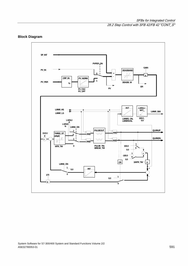
SFBs for Integrated Control 28.2 Step Control with SFB 42/FB 42 "CONT_S"
System Software for S7-300/400 System and Standard Functions Volume 2/2 A5E02790053-01 591
Block Diagram
+
PV_PER
SP_INT
CRP_IN
%
PV_NORM
DEADBANDPV_IN
PV_FACPV_OFF
PVPER_ON
-+
PV
DEADB_W
X
GAIN
ER
0
1
THREE_ST
INTLMNR_SIM
LMNS_ON
LMNUP
LMNDN
PULSEOUT
AND
AND
AND
AND
LMNR_HSLMNR_LS
QLMNDN
QLMNUP
100.00.0
-100.0
0.01/MTR_TM X
INT
LMNLIMIT
OR
10.0
+
-
0.0
LMNS_ON
0
1
0
1
0
01
1
0X
1/TI
1
0
+
DISV
-
adapti
LMNRS_ON,LMNRSVAL
100.0 , 0.0
MTR_TM PULSE_TM,BREAK_TM
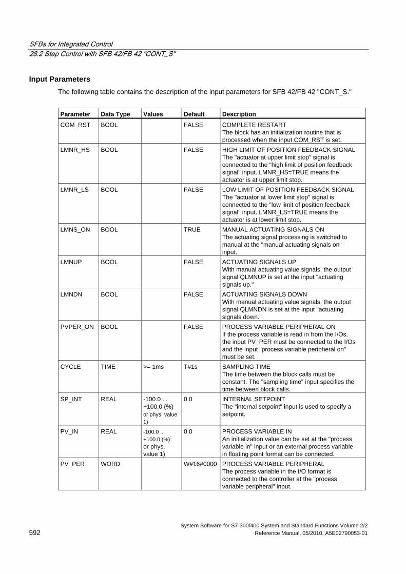
SFBs for Integrated Control 28.2 Step Control with SFB 42/FB 42 "CONT_S"
System Software for S7-300/400 System and Standard Functions Volume 2/2 592 Reference Manual, 05/2010, A5E02790053-01
Input Parameters The following table contains the description of the input parameters for SFB 42/FB 42 "CONT_S."
Parameter Data Type Values Default Description
COM_RST BOOL FALSE COMPLETE RESTART The block has an initialization routine that is processed when the input COM_RST is set.
LMNR_HS BOOL FALSE HIGH LIMIT OF POSITION FEEDBACK SIGNAL The "actuator at upper limit stop" signal is connected to the "high limit of position feedback signal" input. LMNR_HS=TRUE means the actuator is at upper limit stop.
LMNR_LS BOOL FALSE LOW LIMIT OF POSITION FEEDBACK SIGNAL The "actuator at lower limit stop" signal is connected to the "low limit of position feedback signal" input. LMNR_LS=TRUE means the actuator is at lower limit stop.
LMNS_ON BOOL TRUE MANUAL ACTUATING SIGNALS ON The actuating signal processing is switched to manual at the "manual actuating signals on" input.
LMNUP BOOL FALSE ACTUATING SIGNALS UP With manual actuating value signals, the output signal QLMNUP is set at the input "actuating signals up."
LMNDN BOOL FALSE ACTUATING SIGNALS DOWN With manual actuating value signals, the output signal QLMNDN is set at the input "actuating signals down."
PVPER_ON BOOL FALSE PROCESS VARIABLE PERIPHERAL ON If the process variable is read in from the I/Os, the input PV_PER must be connected to the I/Os and the input "process variable peripheral on" must be set.
CYCLE TIME >= 1ms T#1s SAMPLING TIME The time between the block calls must be constant. The "sampling time" input specifies the time between block calls.
SP_INT REAL -100.0 ... +100.0 (%) or phys. value 1)
0.0 INTERNAL SETPOINT The "internal setpoint" input is used to specify a setpoint.
PV_IN REAL -100.0 ... +100.0 (%) or phys. value 1)
0.0 PROCESS VARIABLE IN An initialization value can be set at the "process variable in" input or an external process variable in floating point format can be connected.
PV_PER WORD W#16#0000 PROCESS VARIABLE PERIPHERAL The process variable in the I/O format is connected to the controller at the "process variable peripheral" input.
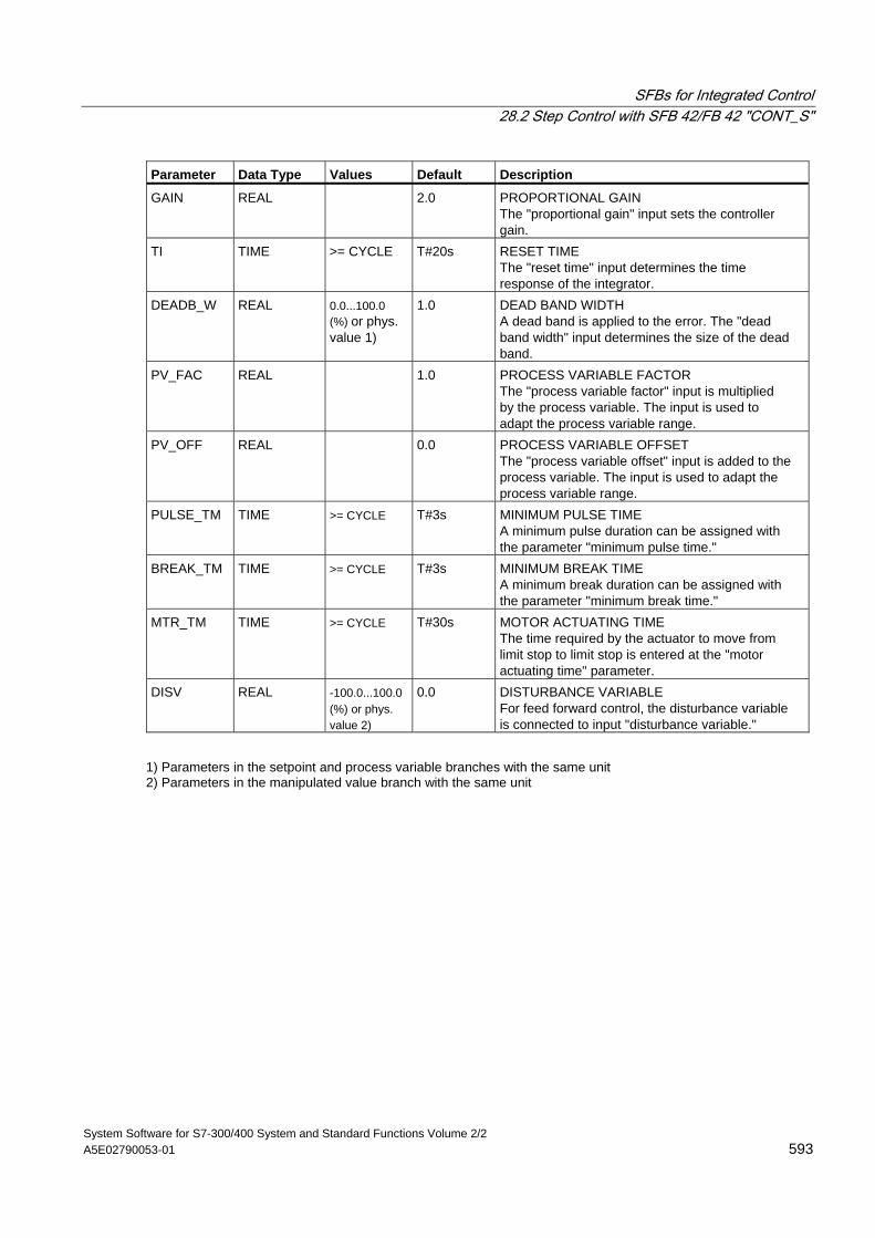
SFBs for Integrated Control 28.2 Step Control with SFB 42/FB 42 "CONT_S"
System Software for S7-300/400 System and Standard Functions Volume 2/2 A5E02790053-01 593
Parameter Data Type Values Default Description
GAIN REAL 2.0 PROPORTIONAL GAIN The "proportional gain" input sets the controller gain.
TI TIME >= CYCLE T#20s RESET TIME The "reset time" input determines the time response of the integrator.
DEADB_W REAL 0.0...100.0 (%) or phys. value 1)
1.0 DEAD BAND WIDTH A dead band is applied to the error. The "dead band width" input determines the size of the dead band.
PV_FAC REAL 1.0 PROCESS VARIABLE FACTOR The "process variable factor" input is multiplied by the process variable. The input is used to adapt the process variable range.
PV_OFF REAL 0.0 PROCESS VARIABLE OFFSET The "process variable offset" input is added to the process variable. The input is used to adapt the process variable range.
PULSE_TM TIME >= CYCLE T#3s MINIMUM PULSE TIME A minimum pulse duration can be assigned with the parameter "minimum pulse time."
BREAK_TM TIME >= CYCLE T#3s MINIMUM BREAK TIME A minimum break duration can be assigned with the parameter "minimum break time."
MTR_TM TIME >= CYCLE T#30s MOTOR ACTUATING TIME The time required by the actuator to move from limit stop to limit stop is entered at the "motor actuating time" parameter.
DISV REAL -100.0...100.0 (%) or phys. value 2)
0.0 DISTURBANCE VARIABLE For feed forward control, the disturbance variable is connected to input "disturbance variable."
1) Parameters in the setpoint and process variable branches with the same unit 2) Parameters in the manipulated value branch with the same unit
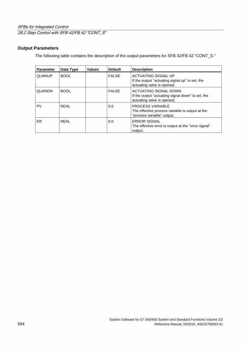
SFBs for Integrated Control 28.2 Step Control with SFB 42/FB 42 "CONT_S"
System Software for S7-300/400 System and Standard Functions Volume 2/2 594 Reference Manual, 05/2010, A5E02790053-01
Output Parameters The following table contains the description of the output parameters for SFB 42/FB 42 "CONT_S."
Parameter Data Type Values Default Description
QLMNUP BOOL FALSE ACTUATING SIGNAL UP If the output "actuating signal up" is set, the actuating valve is opened.
QLMNDN BOOL FALSE ACTUATING SIGNAL DOWN If the output "actuating signal down" is set, the actuating valve is opened.
PV REAL 0.0 PROCESS VARIABLE The effective process variable is output at the "process variable" output.
ER REAL 0.0 ERROR SIGNAL The effective error is output at the "error signal" output.
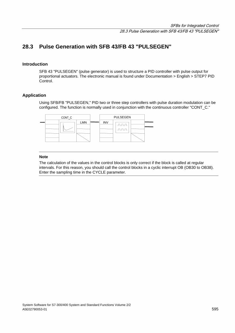
SFBs for Integrated Control 28.3 Pulse Generation with SFB 43/FB 43 "PULSEGEN"
System Software for S7-300/400 System and Standard Functions Volume 2/2 A5E02790053-01 595
28.3 Pulse Generation with SFB 43/FB 43 "PULSEGEN"
Introduction SFB 43 "PULSEGEN" (pulse generator) is used to structure a PID controller with pulse output for proportional actuators. The electronic manual is found under Documentation > English > STEP7 PID Control.
Application Using SFB/FB "PULSEGEN," PID two or three step controllers with pulse duration modulation can be configured. The function is normally used in conjunction with the continuous controller "CONT_C."
LMN
PULSEGEN
INVCONT_C
Note
The calculation of the values in the control blocks is only correct if the block is called at regular intervals. For this reason, you should call the control blocks in a cyclic interrupt OB (OB30 to OB38). Enter the sampling time in the CYCLE parameter.
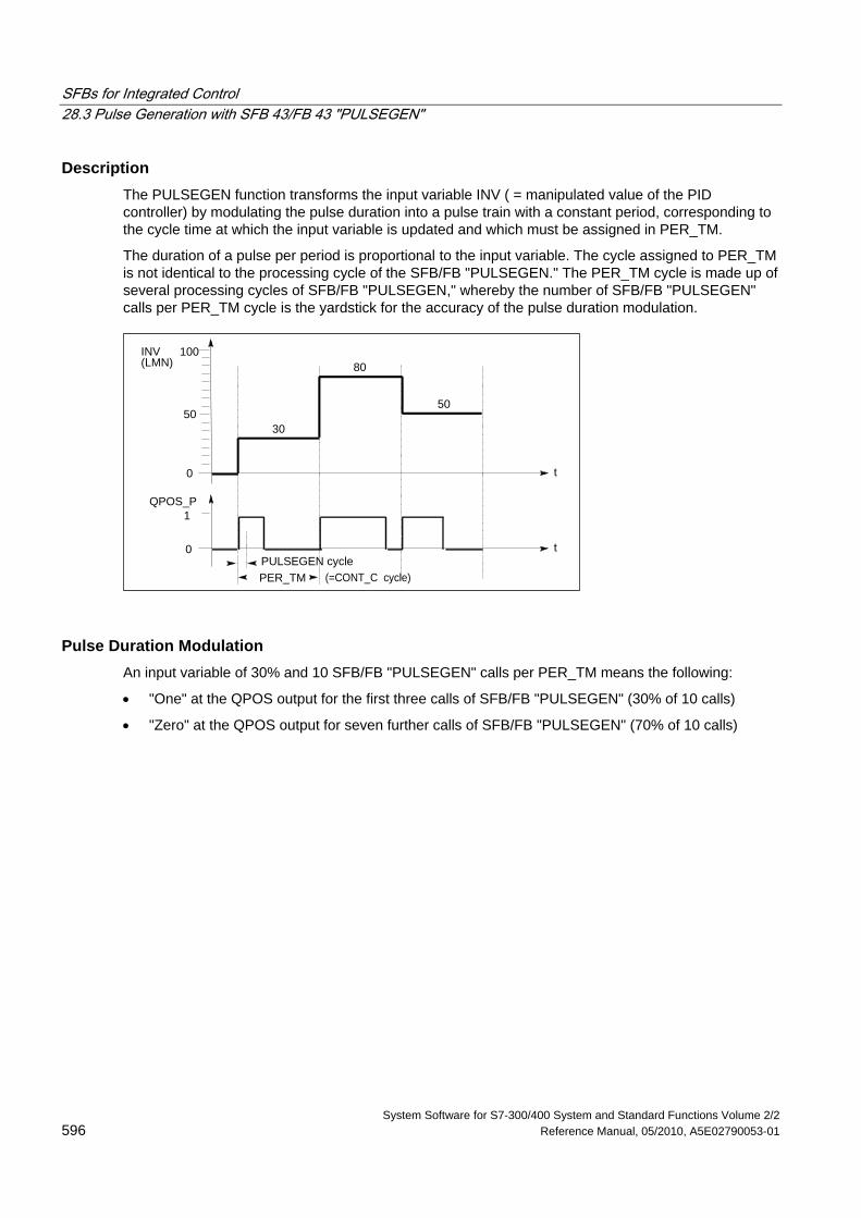
SFBs for Integrated Control 28.3 Pulse Generation with SFB 43/FB 43 "PULSEGEN"
System Software for S7-300/400 System and Standard Functions Volume 2/2 596 Reference Manual, 05/2010, A5E02790053-01
Description The PULSEGEN function transforms the input variable INV ( = manipulated value of the PID controller) by modulating the pulse duration into a pulse train with a constant period, corresponding to the cycle time at which the input variable is updated and which must be assigned in PER_TM.
The duration of a pulse per period is proportional to the input variable. The cycle assigned to PER_TM is not identical to the processing cycle of the SFB/FB "PULSEGEN." The PER_TM cycle is made up of several processing cycles of SFB/FB "PULSEGEN," whereby the number of SFB/FB "PULSEGEN" calls per PER_TM cycle is the yardstick for the accuracy of the pulse duration modulation.
t
INV
QPOS_P
(LMN)
0
50
100
1
0 t
PER_TMPULSEGEN cycle
30
50
80
(=CONT_C cycle)
Pulse Duration Modulation An input variable of 30% and 10 SFB/FB "PULSEGEN" calls per PER_TM means the following:
• "One" at the QPOS output for the first three calls of SFB/FB "PULSEGEN" (30% of 10 calls)
• "Zero" at the QPOS output for seven further calls of SFB/FB "PULSEGEN" (70% of 10 calls)
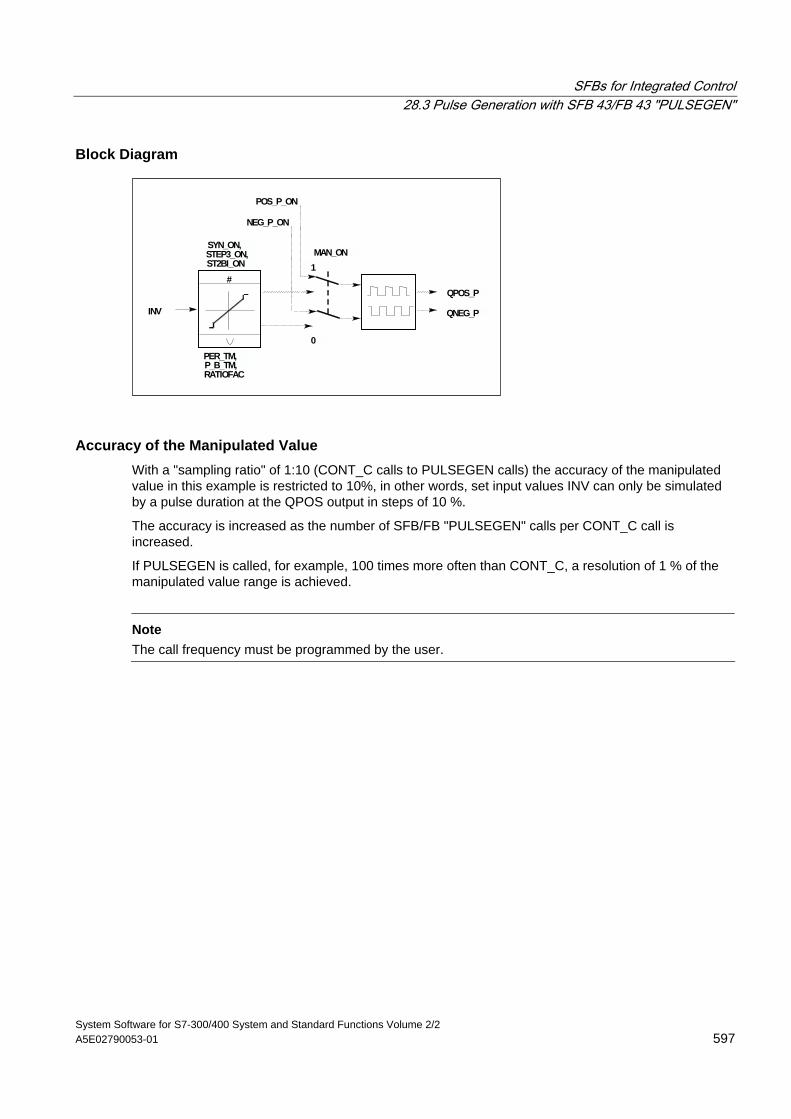
SFBs for Integrated Control 28.3 Pulse Generation with SFB 43/FB 43 "PULSEGEN"
System Software for S7-300/400 System and Standard Functions Volume 2/2 A5E02790053-01 597
Block Diagram
#QPOS_P
QNEG_P
MAN_ON
NEG_P_ON
POS_P_ON
INV
SYN_ON,STEP3_ON,ST2BI_ON
PER_TM,P_B_TM,RATIOFAC
0
1
Accuracy of the Manipulated Value With a "sampling ratio" of 1:10 (CONT_C calls to PULSEGEN calls) the accuracy of the manipulated value in this example is restricted to 10%, in other words, set input values INV can only be simulated by a pulse duration at the QPOS output in steps of 10 %.
The accuracy is increased as the number of SFB/FB "PULSEGEN" calls per CONT_C call is increased.
If PULSEGEN is called, for example, 100 times more often than CONT_C, a resolution of 1 % of the manipulated value range is achieved.
Note
The call frequency must be programmed by the user.
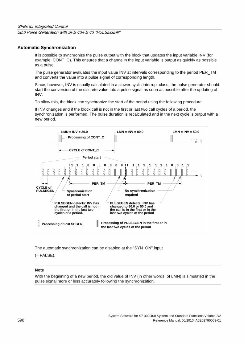
SFBs for Integrated Control 28.3 Pulse Generation with SFB 43/FB 43 "PULSEGEN"
System Software for S7-300/400 System and Standard Functions Volume 2/2 598 Reference Manual, 05/2010, A5E02790053-01
Automatic Synchronization It is possible to synchronize the pulse output with the block that updates the input variable INV (for example, CONT_C). This ensures that a change in the input variable is output as quickly as possible as a pulse.
The pulse generator evaluates the input value INV at intervals corresponding to the period PER_TM and converts the value into a pulse signal of corresponding length.
Since, however, INV is usually calculated in a slower cyclic interrupt class, the pulse generator should start the conversion of the discrete value into a pulse signal as soon as possible after the updating of INV.
To allow this, the block can synchronize the start of the period using the following procedure:
If INV changes and if the block call is not in the first or last two call cycles of a period, the synchronization is performed. The pulse duration is recalculated and in the next cycle is output with a new period.
CYCLE ofPULSEGEN
t
0
t
LMN = INV = 30.0 LMN = INV = 80.0 LMN = INV = 50.0
CYCLE of CONT_C
PER_TM PER_TM
00 0 01 1 0 0 11 1 11 1 1 11 0 0 11
. . . .
. . . .
Period start
Synchronizationof period start
PULSEGEN detects: INV haschanged and the call is not inthe first or in the last twocycles of a period.
PULSEGEN detects: INV haschanged to 80.0 or 50.0 andthe call is in the first or in thelast two cycles of the period
Processing of PULSEGEN Processing of PULSEGEN in the first or in
Processing of CONT_C
No synchronizationrequired
the last two cycles of the period
The automatic synchronization can be disabled at the "SYN_ON" input
(= FALSE).
Note
With the beginning of a new period, the old value of INV (in other words, of LMN) is simulated in the pulse signal more or less accurately following the synchronization.
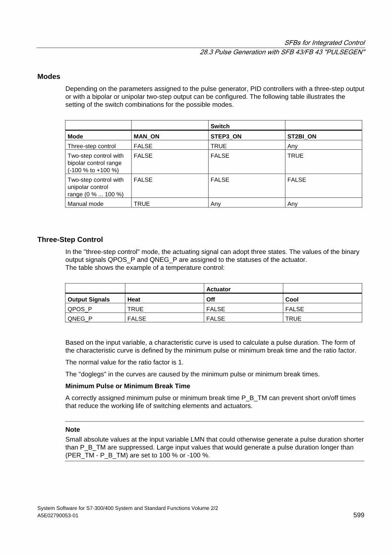
SFBs for Integrated Control 28.3 Pulse Generation with SFB 43/FB 43 "PULSEGEN"
System Software for S7-300/400 System and Standard Functions Volume 2/2 A5E02790053-01 599
Modes Depending on the parameters assigned to the pulse generator, PID controllers with a three-step output or with a bipolar or unipolar two-step output can be configured. The following table illustrates the setting of the switch combinations for the possible modes.
Switch Mode MAN_ON STEP3_ON ST2BI_ON Three-step control FALSE TRUE Any Two-step control with bipolar control range (-100 % to +100 %)
FALSE FALSE TRUE
Two-step control with unipolar control range (0 % ... 100 %)
FALSE FALSE FALSE
Manual mode TRUE Any Any
Three-Step Control In the "three-step control" mode, the actuating signal can adopt three states. The values of the binary output signals QPOS_P and QNEG_P are assigned to the statuses of the actuator. The table shows the example of a temperature control:
Actuator Output Signals Heat Off Cool QPOS_P TRUE FALSE FALSE QNEG_P FALSE FALSE TRUE
Based on the input variable, a characteristic curve is used to calculate a pulse duration. The form of the characteristic curve is defined by the minimum pulse or minimum break time and the ratio factor.
The normal value for the ratio factor is 1.
The "doglegs" in the curves are caused by the minimum pulse or minimum break times.
Minimum Pulse or Minimum Break Time
A correctly assigned minimum pulse or minimum break time P_B_TM can prevent short on/off times that reduce the working life of switching elements and actuators.
Note
Small absolute values at the input variable LMN that could otherwise generate a pulse duration shorter than P_B_TM are suppressed. Large input values that would generate a pulse duration longer than (PER_TM - P_B_TM) are set to 100 % or -100 %.
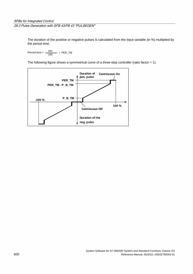
SFBs for Integrated Control 28.3 Pulse Generation with SFB 43/FB 43 "PULSEGEN"
System Software for S7-300/400 System and Standard Functions Volume 2/2 600 Reference Manual, 05/2010, A5E02790053-01
The duration of the positive or negative pulses is calculated from the input variable (in %) multiplied by the period time.
IPeriod time =100INV
∗ PER_TM
The following figure shows a symmetrical curve of a three-step controller (ratio factor = 1).
Duration ofthpos. pulse
-100 %
100 %
PER_TMPER_TM - P_B_TM
P_B_TM
Continuous Off
Continuous On
Duration of theneg. pulse
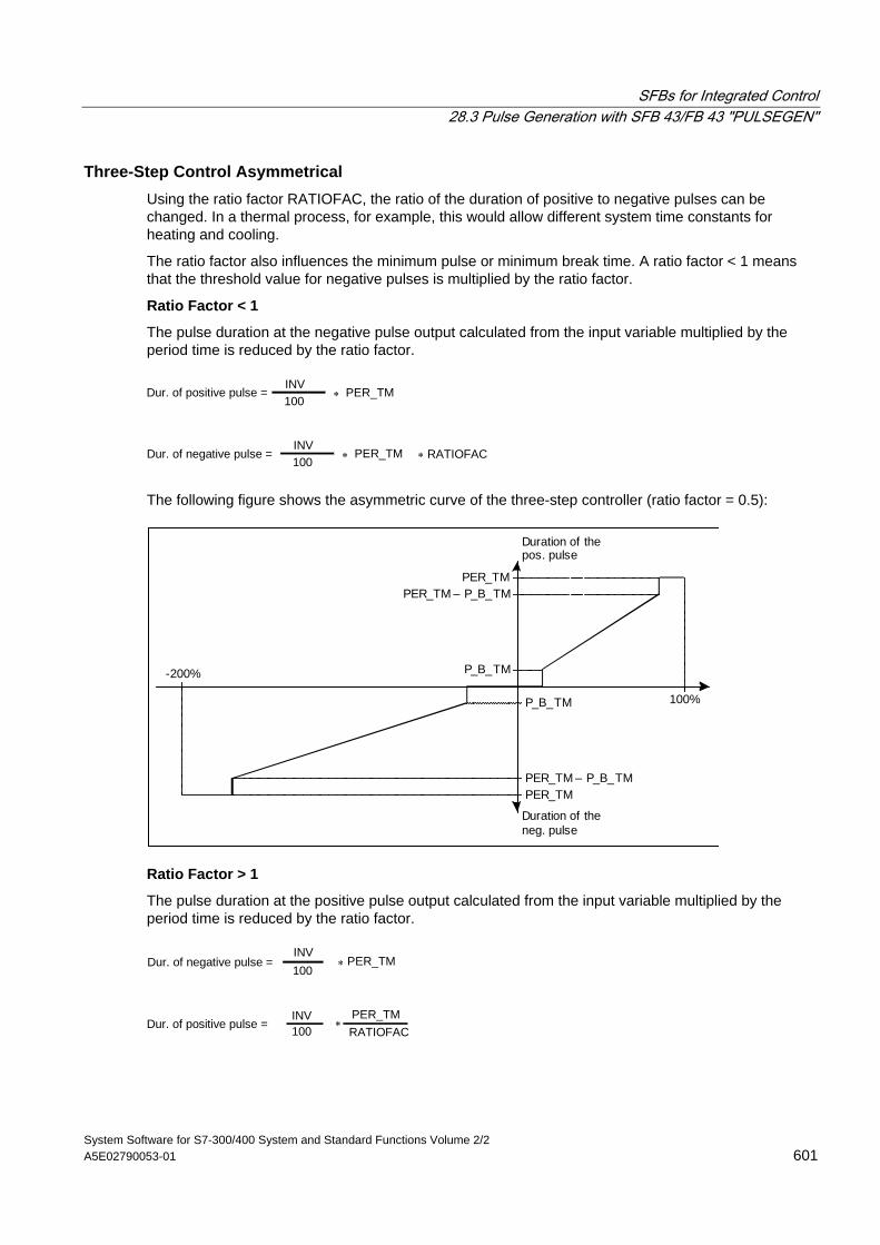
SFBs for Integrated Control 28.3 Pulse Generation with SFB 43/FB 43 "PULSEGEN"
System Software for S7-300/400 System and Standard Functions Volume 2/2 A5E02790053-01 601
Three-Step Control Asymmetrical Using the ratio factor RATIOFAC, the ratio of the duration of positive to negative pulses can be changed. In a thermal process, for example, this would allow different system time constants for heating and cooling.
The ratio factor also influences the minimum pulse or minimum break time. A ratio factor < 1 means that the threshold value for negative pulses is multiplied by the ratio factor.
Ratio Factor < 1
The pulse duration at the negative pulse output calculated from the input variable multiplied by the period time is reduced by the ratio factor.
Dur. of positive pulse =100INV
∗ PER_TM
Dur. of negative pulse =100INV
∗ PER_TM ∗ RATIOFAC
The following figure shows the asymmetric curve of the three-step controller (ratio factor = 0.5):
100%
-200%
PER_TMPER_TM – P_B_TM
P_B_TM
PER_TMPER_TM – P_B_TM
P_B_TM
Duration of thepos. pulse
Duration of theneg. pulse
Ratio Factor > 1
The pulse duration at the positive pulse output calculated from the input variable multiplied by the period time is reduced by the ratio factor.
Dur. of negative pulse =100INV
∗ PER_TM
INV PER_TMRATIOFAC
Dur. of positive pulse = 100 ∗
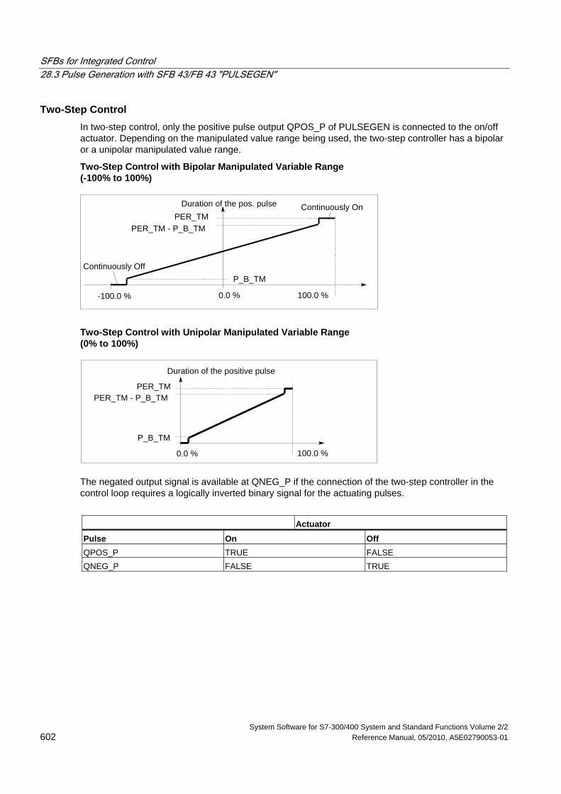
SFBs for Integrated Control 28.3 Pulse Generation with SFB 43/FB 43 "PULSEGEN"
System Software for S7-300/400 System and Standard Functions Volume 2/2 602 Reference Manual, 05/2010, A5E02790053-01
Two-Step Control In two-step control, only the positive pulse output QPOS_P of PULSEGEN is connected to the on/off actuator. Depending on the manipulated value range being used, the two-step controller has a bipolar or a unipolar manipulated value range.
Two-Step Control with Bipolar Manipulated Variable Range (-100% to 100%)
Duration of the pos. pulse
-100.0 % 100.0 %
PER_TMPER_TM - P_B_TM
P_B_TMContinuously Off
Continuously On
0.0 %
Two-Step Control with Unipolar Manipulated Variable Range (0% to 100%)
Duration of the positive pulse
100.0 %
PER_TMPER_TM - P_B_TM
P_B_TM
0.0 %
The negated output signal is available at QNEG_P if the connection of the two-step controller in the control loop requires a logically inverted binary signal for the actuating pulses.
Actuator Pulse On Off QPOS_P TRUE FALSE QNEG_P FALSE TRUE
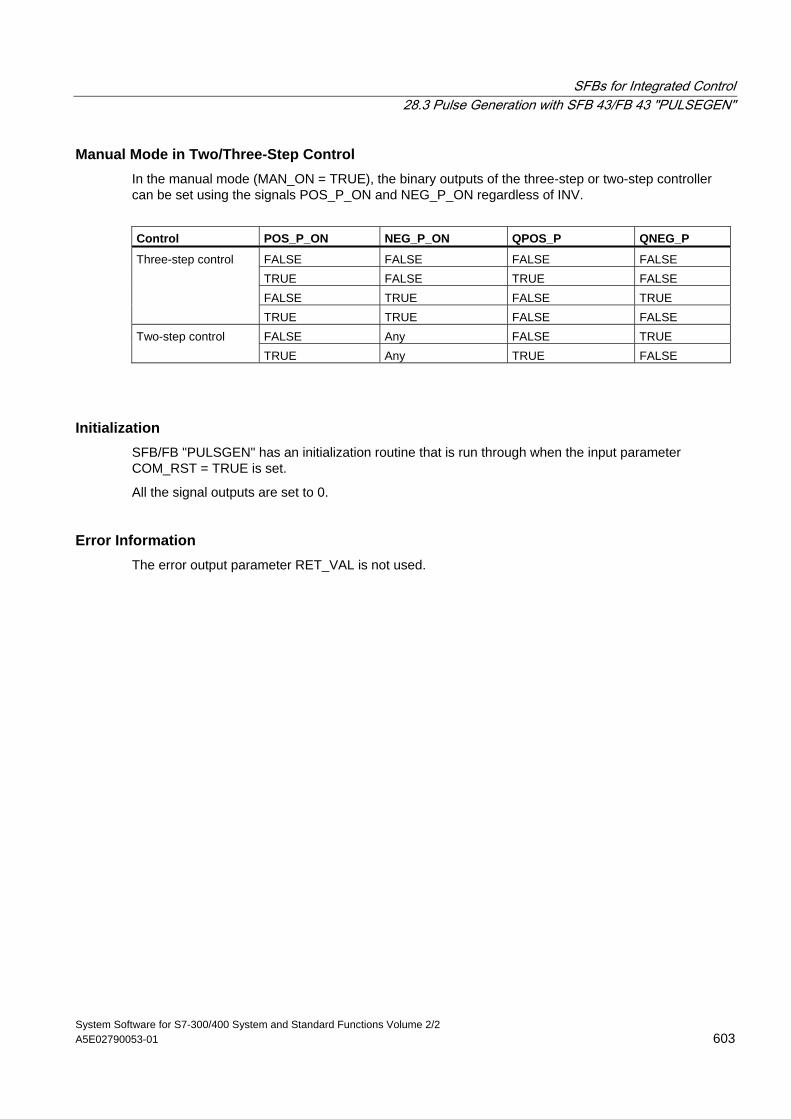
SFBs for Integrated Control 28.3 Pulse Generation with SFB 43/FB 43 "PULSEGEN"
System Software for S7-300/400 System and Standard Functions Volume 2/2 A5E02790053-01 603
Manual Mode in Two/Three-Step Control In the manual mode (MAN_ON = TRUE), the binary outputs of the three-step or two-step controller can be set using the signals POS_P_ON and NEG_P_ON regardless of INV.
Control POS_P_ON NEG_P_ON QPOS_P QNEG_P
FALSE FALSE FALSE FALSE TRUE FALSE TRUE FALSE FALSE TRUE FALSE TRUE
Three-step control
TRUE TRUE FALSE FALSE FALSE Any FALSE TRUE Two-step control TRUE Any TRUE FALSE
Initialization SFB/FB "PULSGEN" has an initialization routine that is run through when the input parameter COM_RST = TRUE is set.
All the signal outputs are set to 0.
Error Information The error output parameter RET_VAL is not used.
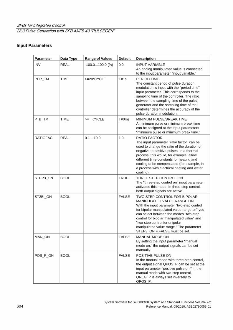
SFBs for Integrated Control 28.3 Pulse Generation with SFB 43/FB 43 "PULSEGEN"
System Software for S7-300/400 System and Standard Functions Volume 2/2 604 Reference Manual, 05/2010, A5E02790053-01
Input Parameters Parameter Data Type Range of Values Default Description
INV REAL -100.0...100.0 (%) 0.0 INPUT VARIABLE An analog manipulated value is connected to the input parameter "input variable."
PER_TM TIME >=20*CYCLE T#1s PERIOD TIME The constant period of pulse duration modulation is input with the "period time" input parameter. This corresponds to the sampling time of the controller. The ratio between the sampling time of the pulse generator and the sampling time of the controller determines the accuracy of the pulse duration modulation.
P_B_TM TIME >= CYCLE T#0ms MINIMUM PULSE/BREAK TIME A minimum pulse or minimum break time can be assigned at the input parameters "minimum pulse or minimum break time."
RATIOFAC REAL 0.1 ...10.0 1.0 RATIO FACTOR The input parameter "ratio factor" can be used to change the ratio of the duration of negative to positive pulses. In a thermal process, this would, for example, allow different time constants for heating and cooling to be compensated (for example, in a process with electrical heating and water cooling).
STEP3_ON BOOL TRUE THREE STEP CONTROL ON The "three-step control on" input parameter activates this mode. In three-step control, both output signals are active.
ST2BI_ON BOOL FALSE TWO STEP CONTROL FOR BIPOLAR MANIPULATED VALUE RANGE ON With the input parameter "two-step control for bipolar manipulated value range on" you can select between the modes "two-step control for bipolar manipulated value" and "two-step control for unipolar manipulated value range." The parameter STEP3_ON = FALSE must be set.
MAN_ON BOOL FALSE MANUAL MODE ON By setting the input parameter "manual mode on," the output signals can be set manually.
POS_P_ON BOOL FALSE POSITIVE PULSE ON In the manual mode with three-step control, the output signal QPOS_P can be set at the input parameter "positive pulse on." In the manual mode with two-step control, QNEG_P is always set inversely to QPOS_P.
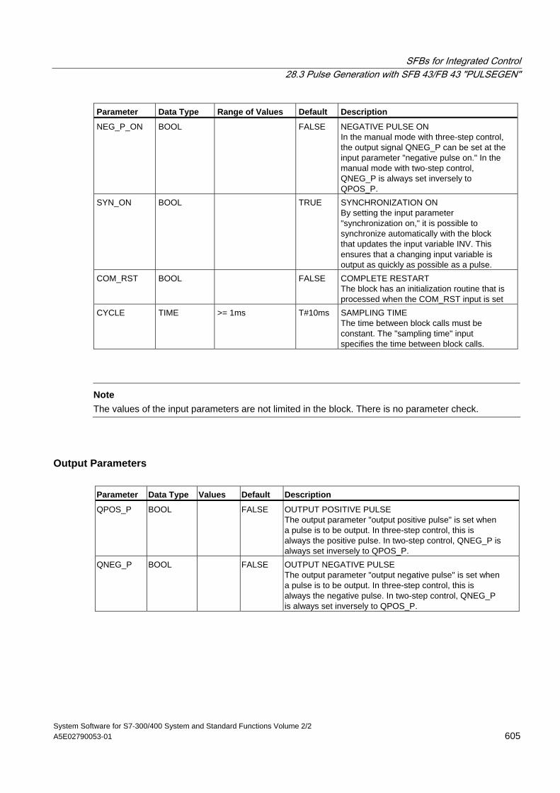
SFBs for Integrated Control 28.3 Pulse Generation with SFB 43/FB 43 "PULSEGEN"
System Software for S7-300/400 System and Standard Functions Volume 2/2 A5E02790053-01 605
Parameter Data Type Range of Values Default Description
NEG_P_ON BOOL FALSE NEGATIVE PULSE ON In the manual mode with three-step control, the output signal QNEG_P can be set at the input parameter "negative pulse on." In the manual mode with two-step control, QNEG_P is always set inversely to QPOS_P.
SYN_ON BOOL TRUE SYNCHRONIZATION ON By setting the input parameter "synchronization on," it is possible to synchronize automatically with the block that updates the input variable INV. This ensures that a changing input variable is output as quickly as possible as a pulse.
COM_RST BOOL FALSE COMPLETE RESTART The block has an initialization routine that is processed when the COM_RST input is set
CYCLE TIME >= 1ms T#10ms SAMPLING TIME The time between block calls must be constant. The "sampling time" input specifies the time between block calls.
Note
The values of the input parameters are not limited in the block. There is no parameter check.
Output Parameters Parameter Data Type Values Default Description
QPOS_P BOOL FALSE OUTPUT POSITIVE PULSE The output parameter "output positive pulse" is set when a pulse is to be output. In three-step control, this is always the positive pulse. In two-step control, QNEG_P is always set inversely to QPOS_P.
QNEG_P BOOL FALSE OUTPUT NEGATIVE PULSE The output parameter "output negative pulse" is set when a pulse is to be output. In three-step control, this is always the negative pulse. In two-step control, QNEG_P is always set inversely to QPOS_P.
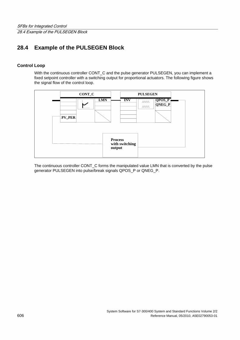
SFBs for Integrated Control 28.4 Example of the PULSEGEN Block
System Software for S7-300/400 System and Standard Functions Volume 2/2 606 Reference Manual, 05/2010, A5E02790053-01
28.4 Example of the PULSEGEN Block
Control Loop With the continuous controller CONT_C and the pulse generator PULSEGEN, you can implement a fixed setpoint controller with a switching output for proportional actuators. The following figure shows the signal flow of the control loop.
Processwith switchingoutput
PULSEGENCONT_CLMN
PV_PER
INV QPOS_PQNEG_P
The continuous controller CONT_C forms the manipulated value LMN that is converted by the pulse generator PULSEGEN into pulse/break signals QPOS_P or QNEG_P.
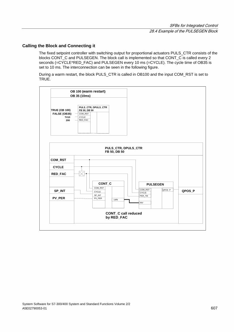
SFBs for Integrated Control 28.4 Example of the PULSEGEN Block
System Software for S7-300/400 System and Standard Functions Volume 2/2 A5E02790053-01 607
Calling the Block and Connecting it The fixed setpoint controller with switching output for proportional actuators PULS_CTR consists of the blocks CONT_C and PULSEGEN. The block call is implemented so that CONT_C is called every 2 seconds (=CYCLE*RED_FAC) and PULSEGEN every 10 ms (=CYCLE). The cycle time of OB35 is set to 10 ms. The interconnection can be seen in the following figure.
During a warm restart, the block PULS_CTR is called in OB100 and the input COM_RST is set to TRUE.
OB 100 (warm restart)OB 35 (10ms)
TRUE (OB 100)FALSE (OB35)
T#10200
PULS_CTR, DPULS_CTRFB 50, DB 50
PULS_CTR, DPULS_CTRFB 50, DB 50
COM_RST
CYCLERED_FAC
COM_RST
CYCLE
RED_FAC
SP_INT
PV_PER
COM_RSTCYCLE
COM_RST
CYCLE
PER_TM
INV
QPOS_P
SP_INTPV_PER LMN
QPOS_P
PULSEGENCONT_C
CONT_C call reducedby RED_FAC
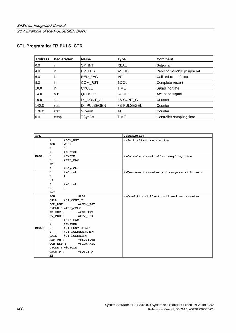
SFBs for Integrated Control 28.4 Example of the PULSEGEN Block
System Software for S7-300/400 System and Standard Functions Volume 2/2 608 Reference Manual, 05/2010, A5E02790053-01
STL Program for FB PULS_CTR Address Declaration Name Type Comment
0.0 in SP_INT REAL Setpoint 4.0 in PV_PER WORD Process variable peripheral 6.0 in RED_FAC INT Call reduction factor 8.0 in COM_RST BOOL Complete restart 10.0 in CYCLE TIME Sampling time 14.0 out QPOS_P BOOL Actuating signal 16.0 stat DI_CONT_C FB-CONT_C Counter 142.0 stat DI_PULSEGEN FB-PULSEGEN Counter 176.0 stat SCount INT Counter 0.0 temp TCycCtr TIME Controller sampling time
STL Description A #COM_RST JCN M001 L 0 T #sCount
//Initialization routine
M001: L #CYCLE L #RED_FAC *D T #tCycCtr
//Calculate controller sampling time
L #sCount L 1 -I T #sCount L 0 <=I
//Decrement counter and compare with zero
JCN M002 CALL #DI_CONT_C COM_RST : =#COM_RST CYCLE : =#tCycCtr SP_INT : =#SP_INT PV_PER : =#PV_PER L #RED_FAC T #sCount M002: L #DI_CONT_C.LMN T #DI_PULSEGEN.INV CALL #DI_PULSEGEN PER_TM : =#tCycCtr COM_RST : =#COM_RST CYCLE : =#CYCLE QPOS_P : =#QPOS_P BE
//Conditional block call and set counter
System Software for S7-300/400 System and Standard Functions Volume 2/2 Reference Manual, 05/2010, A5E02790053-01 609
29 SFBs for Compact CPUs
29.1 Positioning With Analog Output Using SFB 44 "Analog"
Description To control the positioning functions via the user program, use SFB ANALOG (SFB 44).
A fixed assigned analog output controls the power stage with a voltage (voltage signal) of ±10 V or with a current (current signal) of ±20 mA.
• After the acceleration phase (RAM_UP) the drive approaches the target with the speed (VSetpoint).
• At the braking point, that is calculated by the CPU, the deceleration (RAMP_DN) up to the change-over point is initialized.
• Once the change-over point is reached, run is continued with creep speed (VCreep).
• The drive is switched off at the cut-off point.
• The change-over point and the cut-off point are determined for every Step Approach in the parameter values change-over difference and cut-off difference you have specified. The change-over difference and cut-off difference can be determined differently for the forward motion (in plus direction) and for the reverse motion (in minus direction).
• The run is completed (WORKING = FALSE) when the cut-off point is reached. A new run can then be started.
• The specified target is reached (POS_RCD = TRUE) when the current position value has reached the target range. If the current position value drifts off without a new run having been started the "Position reached" signal is not reset again.
When the change-over difference is smaller than the cut-off difference, the drive is slowed down as of the braking point to the speed setpoint 0.
Basic Parameters: Here we describe the SFB parameters which apply to all operating modes. The parameters specific to the operating mode are described with the individual operating modes.
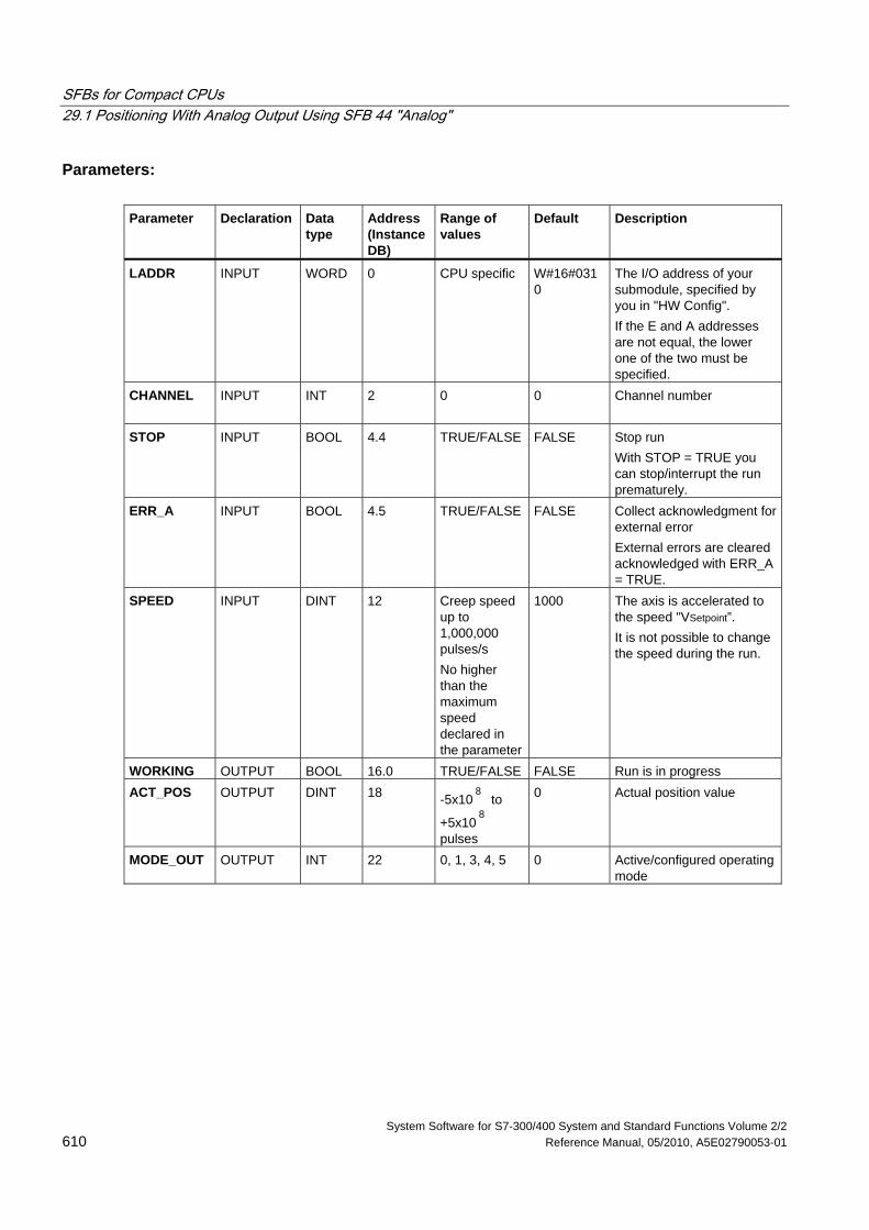
SFBs for Compact CPUs 29.1 Positioning With Analog Output Using SFB 44 "Analog"
System Software for S7-300/400 System and Standard Functions Volume 2/2 610 Reference Manual, 05/2010, A5E02790053-01
Parameters: Parameter Declaration Data
type Address (Instance DB)
Range of values
Default Description
LADDR INPUT WORD 0 CPU specific W#16#0310
The I/O address of your submodule, specified by you in "HW Config". If the E and A addresses are not equal, the lower one of the two must be specified.
CHANNEL INPUT INT 2
0 0 Channel number
STOP INPUT BOOL 4.4 TRUE/FALSE FALSE Stop run With STOP = TRUE you can stop/interrupt the run prematurely.
ERR_A INPUT BOOL 4.5 TRUE/FALSE FALSE Collect acknowledgment for external error External errors are cleared acknowledged with ERR_A = TRUE.
SPEED INPUT DINT 12 Creep speed up to 1,000,000 pulses/s No higher than the maximum speed declared in the parameter
1000 The axis is accelerated to the speed "VSetpoint”. It is not possible to change the speed during the run.
WORKING OUTPUT BOOL 16.0 TRUE/FALSE FALSE Run is in progress ACT_POS OUTPUT DINT 18 -5x10
8 to
+5x10⁸
pulses
0 Actual position value
MODE_OUT OUTPUT INT 22 0, 1, 3, 4, 5 0 Active/configured operating mode
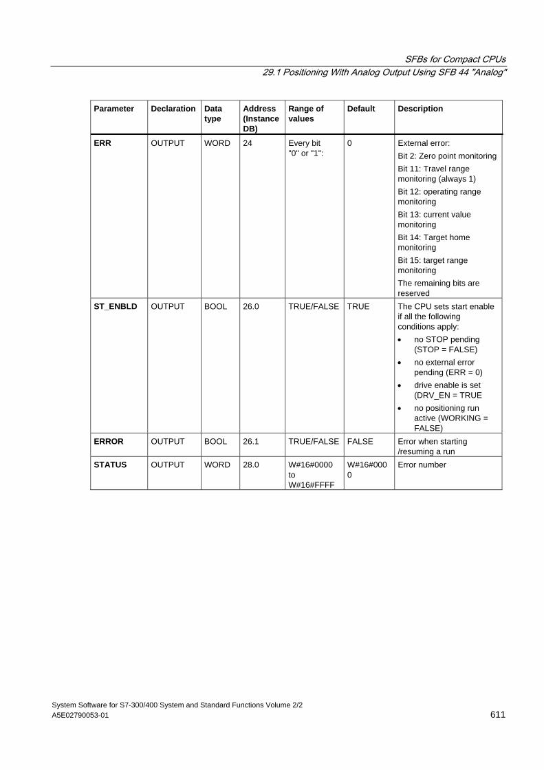
SFBs for Compact CPUs 29.1 Positioning With Analog Output Using SFB 44 "Analog"
System Software for S7-300/400 System and Standard Functions Volume 2/2 A5E02790053-01 611
Parameter Declaration Data type
Address (Instance DB)
Range of values
Default Description
ERR OUTPUT WORD 24 Every bit "0" or "1":
0 External error: Bit 2: Zero point monitoring Bit 11: Travel range monitoring (always 1) Bit 12: operating range monitoring Bit 13: current value monitoring Bit 14: Target home monitoring Bit 15: target range monitoring The remaining bits are reserved
ST_ENBLD OUTPUT BOOL 26.0 TRUE/FALSE TRUE The CPU sets start enable if all the following conditions apply: • no STOP pending
(STOP = FALSE) • no external error
pending (ERR = 0) • drive enable is set
(DRV_EN = TRUE • no positioning run
active (WORKING = FALSE)
ERROR OUTPUT BOOL 26.1 TRUE/FALSE FALSE Error when starting /resuming a run
STATUS OUTPUT WORD 28.0 W#16#0000 to W#16#FFFF
W#16#0000
Error number
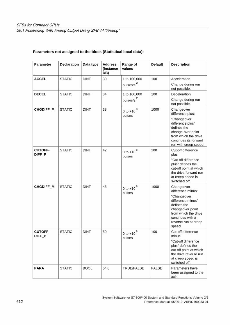
SFBs for Compact CPUs 29.1 Positioning With Analog Output Using SFB 44 "Analog"
System Software for S7-300/400 System and Standard Functions Volume 2/2 612 Reference Manual, 05/2010, A5E02790053-01
Parameters not assigned to the block (Statistical local data):
Parameter Declaration Data type Address
(Instance DB)
Range of values
Default Description
ACCEL STATIC DINT 30 1 to 100,000
pulses/s2
100 Acceleration Change during run not possible.
DECEL STATIC DINT 34 1 to 100,000
pulses/s2
100 Deceleration Change during run not possible.
CHGDIFF_P STATIC DINT 38 0 to +108
pulses
1000 Changeover difference plus: "Changeover difference plus" defines the change-over point from which the drive continues its forward run with creep speed.
CUTOFF- DIFF_P
STATIC DINT 42 0 to +108
pulses
100 Cut-off difference plus: "Cut-off difference plus" defines the cut-off point at which the drive forward run at creep speed is switched off.
CHGDIFF_M STATIC DINT 46 0 to +108
pulses
1000 Changeover difference minus: "Changeover difference minus" defines the changeover point from which the drive continues with a reverse run at creep speed.
CUTOFF- DIFF_P
STATIC DINT 50 0 to +108
pulses
100 Cut-off difference minus: "Cut-off difference plus" defines the cut-off point at which the drive reverse run at creep speed is switched off.
PARA STATIC BOOL 54.0 TRUE/FALSE FALSE Parameters have been assigned to the axis
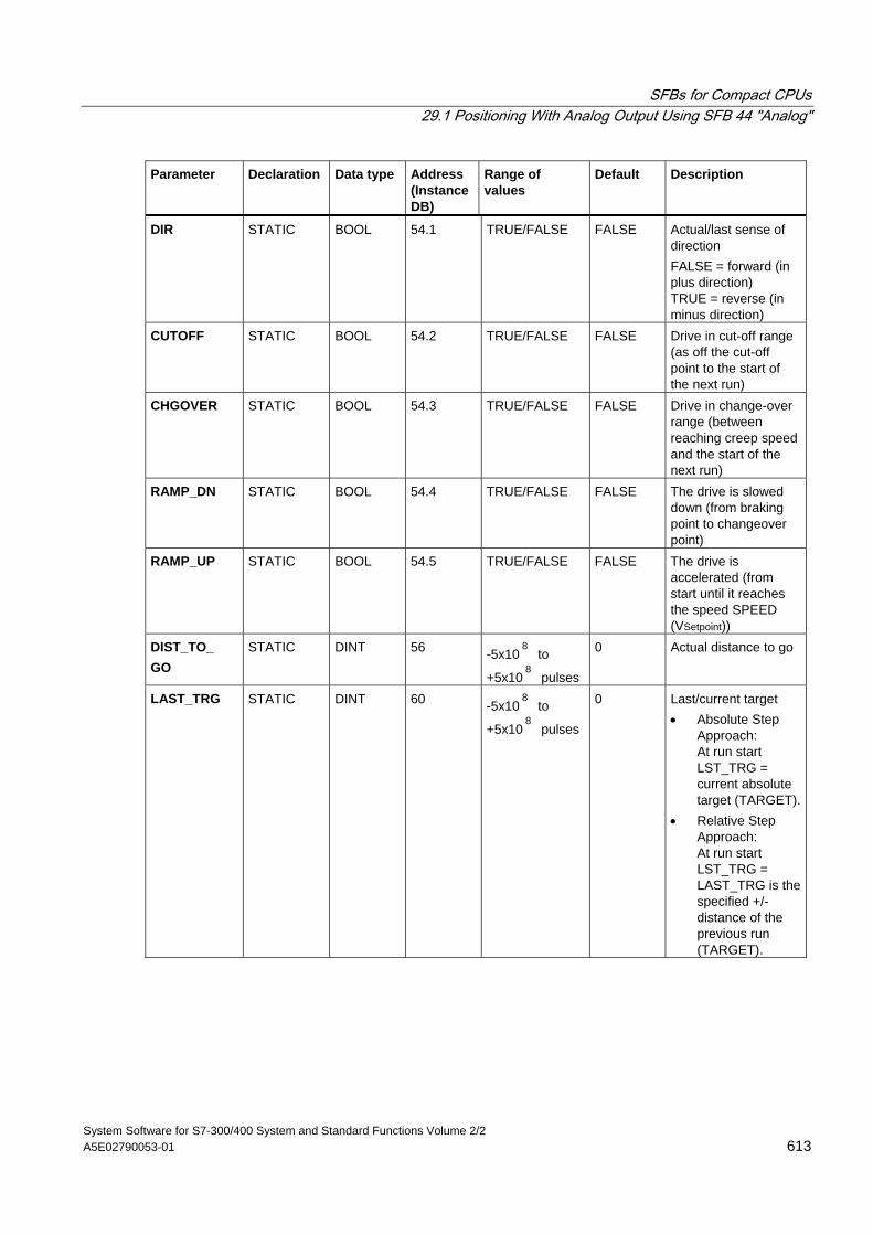
SFBs for Compact CPUs 29.1 Positioning With Analog Output Using SFB 44 "Analog"
System Software for S7-300/400 System and Standard Functions Volume 2/2 A5E02790053-01 613
Parameter Declaration Data type Address (Instance DB)
Range of values
Default Description
DIR STATIC BOOL 54.1 TRUE/FALSE FALSE Actual/last sense of direction FALSE = forward (in plus direction) TRUE = reverse (in minus direction)
CUTOFF STATIC BOOL 54.2 TRUE/FALSE FALSE Drive in cut-off range (as off the cut-off point to the start of the next run)
CHGOVER STATIC BOOL 54.3 TRUE/FALSE FALSE Drive in change-over range (between reaching creep speed and the start of the next run)
RAMP_DN STATIC BOOL 54.4 TRUE/FALSE FALSE The drive is slowed down (from braking point to changeover point)
RAMP_UP STATIC BOOL 54.5 TRUE/FALSE FALSE The drive is accelerated (from start until it reaches the speed SPEED (VSetpoint))
DIST_TO_ GO
STATIC DINT 56 -5x10⁸
to
+5x10⁸
pulses
0 Actual distance to go
LAST_TRG STATIC DINT 60 -5x10⁸
to
+5x10⁸
pulses
0 Last/current target • Absolute Step
Approach: At run start LST_TRG = current absolute target (TARGET).
• Relative Step Approach: At run start LST_TRG = LAST_TRG is the specified +/- distance of the previous run (TARGET).
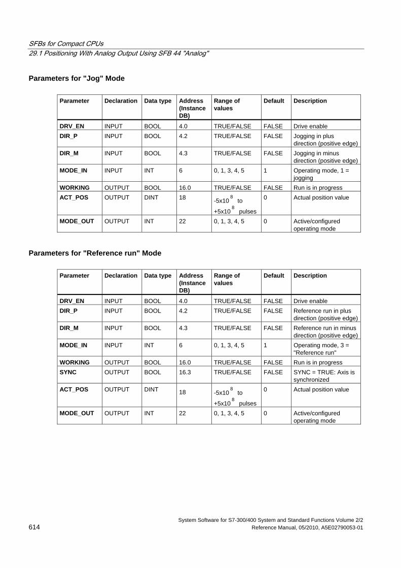
SFBs for Compact CPUs 29.1 Positioning With Analog Output Using SFB 44 "Analog"
System Software for S7-300/400 System and Standard Functions Volume 2/2 614 Reference Manual, 05/2010, A5E02790053-01
Parameters for "Jog" Mode Parameter Declaration Data type Address
(Instance DB)
Range of values
Default Description
DRV_EN INPUT BOOL 4.0 TRUE/FALSE FALSE Drive enable DIR_P INPUT BOOL 4.2 TRUE/FALSE FALSE Jogging in plus
direction (positive edge)DIR_M INPUT BOOL 4.3 TRUE/FALSE FALSE Jogging in minus
direction (positive edge)MODE_IN INPUT INT 6 0, 1, 3, 4, 5 1 Operating mode, 1 =
jogging WORKING OUTPUT BOOL 16.0 TRUE/FALSE FALSE Run is in progress ACT_POS OUTPUT DINT 18 -5x10
8 to
+5x10⁸
pulses
0 Actual position value
MODE_OUT OUTPUT INT 22 0, 1, 3, 4, 5 0 Active/configured operating mode
Parameters for "Reference run" Mode Parameter Declaration Data type Address
(Instance DB)
Range of values
Default Description
DRV_EN INPUT BOOL 4.0 TRUE/FALSE FALSE Drive enable DIR_P INPUT BOOL 4.2 TRUE/FALSE FALSE Reference run in plus
direction (positive edge)DIR_M INPUT BOOL 4.3 TRUE/FALSE FALSE Reference run in minus
direction (positive edge)MODE_IN INPUT INT 6 0, 1, 3, 4, 5 1 Operating mode, 3 =
"Reference run" WORKING OUTPUT BOOL 16.0 TRUE/FALSE FALSE Run is in progress SYNC OUTPUT BOOL 16.3 TRUE/FALSE FALSE SYNC = TRUE: Axis is
synchronized ACT_POS OUTPUT DINT 18 -5x10
8 to
+5x10⁸
pulses
0 Actual position value
MODE_OUT OUTPUT INT 22 0, 1, 3, 4, 5 0 Active/configured operating mode
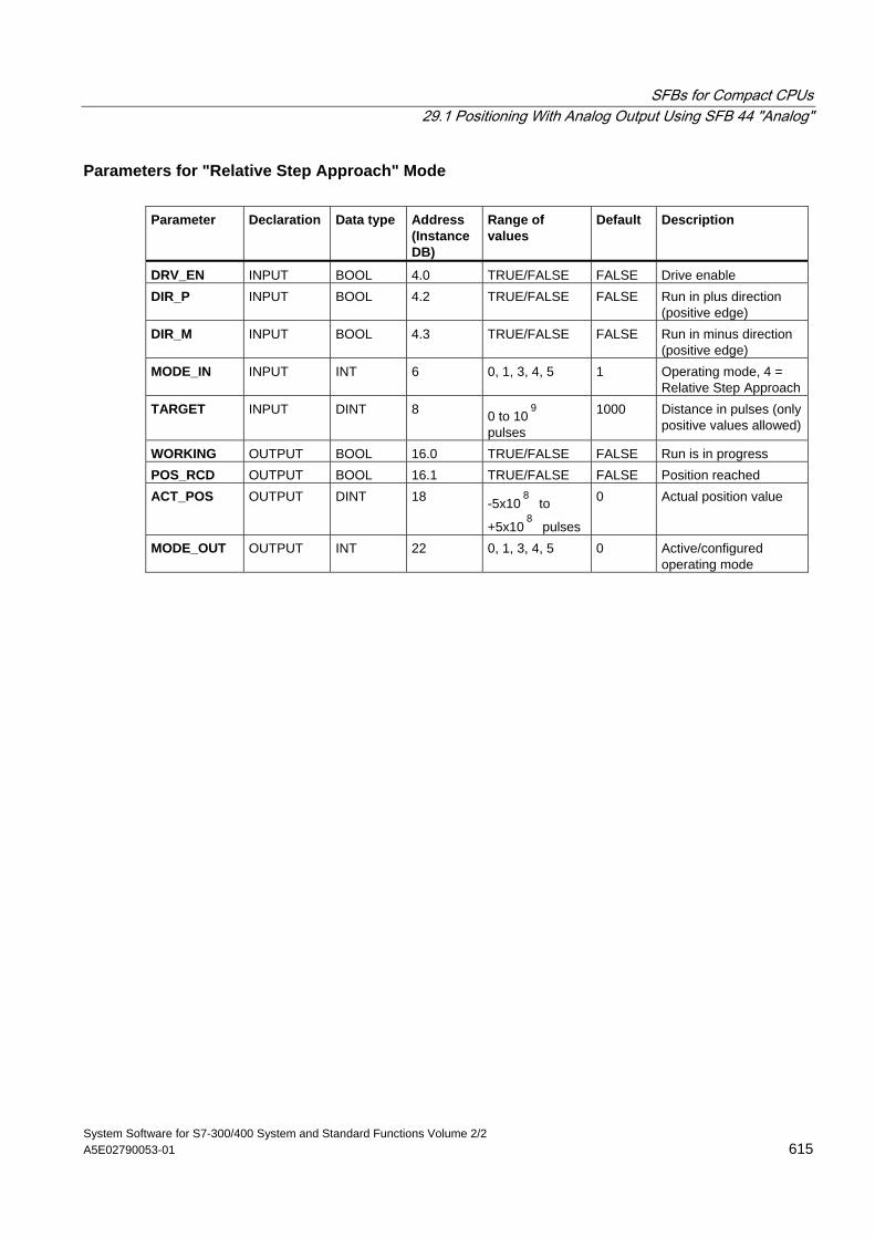
SFBs for Compact CPUs 29.1 Positioning With Analog Output Using SFB 44 "Analog"
System Software for S7-300/400 System and Standard Functions Volume 2/2 A5E02790053-01 615
Parameters for "Relative Step Approach" Mode Parameter Declaration Data type Address
(Instance DB)
Range of values
Default Description
DRV_EN INPUT BOOL 4.0 TRUE/FALSE FALSE Drive enable DIR_P INPUT BOOL 4.2 TRUE/FALSE FALSE Run in plus direction
(positive edge) DIR_M INPUT BOOL 4.3 TRUE/FALSE FALSE Run in minus direction
(positive edge) MODE_IN INPUT INT 6 0, 1, 3, 4, 5 1 Operating mode, 4 =
Relative Step ApproachTARGET INPUT DINT 8 0 to 10
9
pulses
1000 Distance in pulses (only positive values allowed)
WORKING OUTPUT BOOL 16.0 TRUE/FALSE FALSE Run is in progress POS_RCD OUTPUT BOOL 16.1 TRUE/FALSE FALSE Position reached ACT_POS OUTPUT DINT 18 -5x10
8 to
+5x10⁸
pulses
0 Actual position value
MODE_OUT OUTPUT INT 22 0, 1, 3, 4, 5 0 Active/configured operating mode
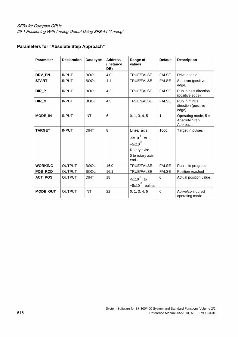
SFBs for Compact CPUs 29.1 Positioning With Analog Output Using SFB 44 "Analog"
System Software for S7-300/400 System and Standard Functions Volume 2/2 616 Reference Manual, 05/2010, A5E02790053-01
Parameters for "Absolute Step Approach" Parameter Declaration Data type Address
(Instance DB)
Range of values
Default Description
DRV_EN INPUT BOOL 4.0 TRUE/FALSE FALSE Drive enable START INPUT BOOL 4.1 TRUE/FALSE FALSE Start run (positive
edge) DIR_P INPUT BOOL 4.2 TRUE/FALSE FALSE Run in plus direction
(positive edge) DIR_M INPUT BOOL 4.3 TRUE/FALSE FALSE Run in minus
direction (positive edge)
MODE_IN INPUT INT 6 0, 1, 3, 4, 5 1 Operating mode, 5 = Absolute Step Approach
TARGET INPUT DINT 8 Linear axis
-5x10⁸
to
+5x10⁸
Rotary axis: 0 to rotary axis end -1
1000 Target in pulses
WORKING OUTPUT BOOL 16.0 TRUE/FALSE FALSE Run is in progress POS_RCD OUTPUT BOOL 16.1 TRUE/FALSE FALSE Position reached ACT_POS OUTPUT DINT 18 -5x10
8 to
+5x10⁸
pulses
0 Actual position value
MODE_OUT OUTPUT INT 22 0, 1, 3, 4, 5 0 Active/configured operating mode
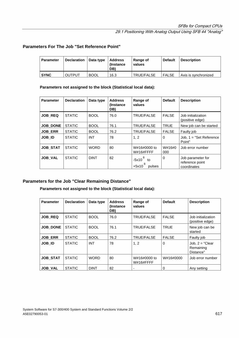
SFBs for Compact CPUs 29.1 Positioning With Analog Output Using SFB 44 "Analog"
System Software for S7-300/400 System and Standard Functions Volume 2/2 A5E02790053-01 617
Parameters For The Job "Set Reference Point" Parameter Declaration Data type Address
(Instance DB)
Range of values
Default Description
SYNC OUTPUT BOOL 16.3 TRUE/FALSE FALSE Axis is synchronized
Parameters not assigned to the block (Statistical local data):
Parameter Declaration Data type Address
(Instance DB)
Range of values
Default Description
JOB_REQ STATIC BOOL 76.0 TRUE/FALSE FALSE Job initialization (positive edge)
JOB_DONE STATIC BOOL 76.1 TRUE/FALSE TRUE New job can be started JOB_ERR STATIC BOOL 76.2 TRUE/FALSE FALSE Faulty job JOB_ID STATIC INT 78 1, 2 0 Job, 1 = "Set Reference
Point" JOB_STAT STATIC WORD 80 W#16#0000 to
W#16#FFFF W#16#0000
Job error number
JOB_VAL STATIC DINT 82 -5x10⁸
to
+5x10⁸
pulses
0 Job parameter for reference point coordinates
Parameters for the Job "Clear Remaining Distance" Parameters not assigned to the block (Statistical local data):
Parameter Declaration Data type Address
(Instance DB)
Range of values
Default Description
JOB_REQ STATIC BOOL 76.0 TRUE/FALSE FALSE Job initialization (positive edge)
JOB_DONE STATIC BOOL 76.1 TRUE/FALSE TRUE New job can be started
JOB_ERR STATIC BOOL 76.2 TRUE/FALSE FALSE Faulty job JOB_ID STATIC INT 78 1, 2 0 Job, 2 = "Clear
Remaining Distance"
JOB_STAT STATIC WORD 80 W#16#0000 to W#16#FFFF
W#16#0000 Job error number
JOB_VAL STATIC DINT 82 - 0 Any setting
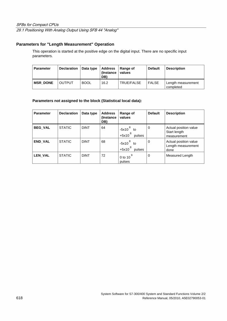
SFBs for Compact CPUs 29.1 Positioning With Analog Output Using SFB 44 "Analog"
System Software for S7-300/400 System and Standard Functions Volume 2/2 618 Reference Manual, 05/2010, A5E02790053-01
Parameters for "Length Measurement" Operation This operation is started at the positive edge on the digital input. There are no specific input parameters.
Parameter Declaration Data type Address
(Instance DB)
Range of values
Default Description
MSR_DONE OUTPUT BOOL 16.2 TRUE/FALSE FALSE Length measurement completed
Parameters not assigned to the block (Statistical local data):
Parameter Declaration Data type Address
(Instance DB)
Range of values
Default Description
BEG_VAL STATIC DINT 64 -5x10⁸
to
+5x10⁸
pulses
0 Actual position value Start length measurement
END_VAL STATIC
DINT 68 -5x10⁸
to
+5x10⁸
pulses
0 Actual position value Length measurement done
LEN_VAL STATIC DINT 72 0 to 109
pulses
0 Measured Length
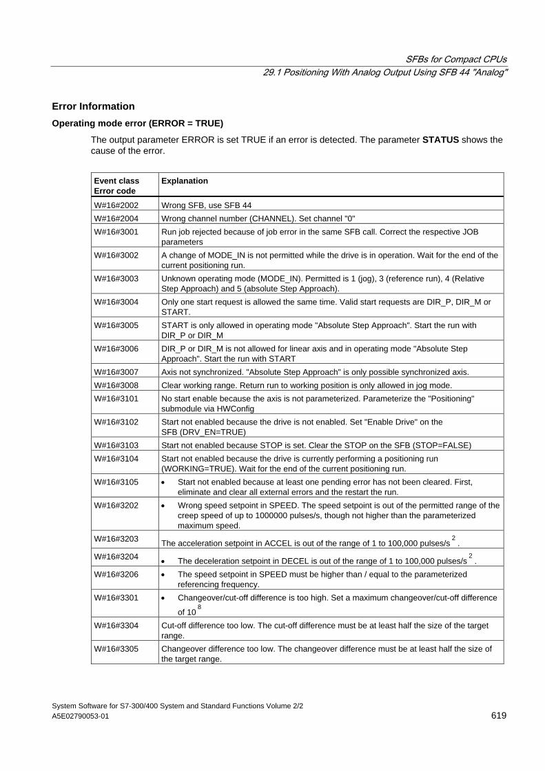
SFBs for Compact CPUs 29.1 Positioning With Analog Output Using SFB 44 "Analog"
System Software for S7-300/400 System and Standard Functions Volume 2/2 A5E02790053-01 619
Error Information Operating mode error (ERROR = TRUE)
The output parameter ERROR is set TRUE if an error is detected. The parameter STATUS shows the cause of the error.
Event class Error code
Explanation
W#16#2002 Wrong SFB, use SFB 44 W#16#2004 Wrong channel number (CHANNEL). Set channel "0" W#16#3001 Run job rejected because of job error in the same SFB call. Correct the respective JOB
parameters W#16#3002 A change of MODE_IN is not permitted while the drive is in operation. Wait for the end of the
current positioning run. W#16#3003 Unknown operating mode (MODE_IN). Permitted is 1 (jog), 3 (reference run), 4 (Relative
Step Approach) and 5 (absolute Step Approach). W#16#3004 Only one start request is allowed the same time. Valid start requests are DIR_P, DIR_M or
START. W#16#3005 START is only allowed in operating mode "Absolute Step Approach". Start the run with
DIR_P or DIR_M W#16#3006 DIR_P or DIR_M is not allowed for linear axis and in operating mode "Absolute Step
Approach". Start the run with START W#16#3007 Axis not synchronized. "Absolute Step Approach" is only possible synchronized axis. W#16#3008 Clear working range. Return run to working position is only allowed in jog mode. W#16#3101 No start enable because the axis is not parameterized. Parameterize the "Positioning"
submodule via HWConfig W#16#3102 Start not enabled because the drive is not enabled. Set "Enable Drive" on the
SFB (DRV_EN=TRUE) W#16#3103 Start not enabled because STOP is set. Clear the STOP on the SFB (STOP=FALSE) W#16#3104 Start not enabled because the drive is currently performing a positioning run
(WORKING=TRUE). Wait for the end of the current positioning run. W#16#3105 • Start not enabled because at least one pending error has not been cleared. First,
eliminate and clear all external errors and the restart the run. W#16#3202 • Wrong speed setpoint in SPEED. The speed setpoint is out of the permitted range of the
creep speed of up to 1000000 pulses/s, though not higher than the parameterized maximum speed.
W#16#3203 The acceleration setpoint in ACCEL is out of the range of 1 to 100,000 pulses/s2
. W#16#3204 • The deceleration setpoint in DECEL is out of the range of 1 to 100,000 pulses/s
2.
W#16#3206 • The speed setpoint in SPEED must be higher than / equal to the parameterized referencing frequency.
W#16#3301 • Changeover/cut-off difference is too high. Set a maximum changeover/cut-off difference
of 108
W#16#3304 Cut-off difference too low. The cut-off difference must be at least half the size of the target
range. W#16#3305 Changeover difference too low. The changeover difference must be at least half the size of
the target range.
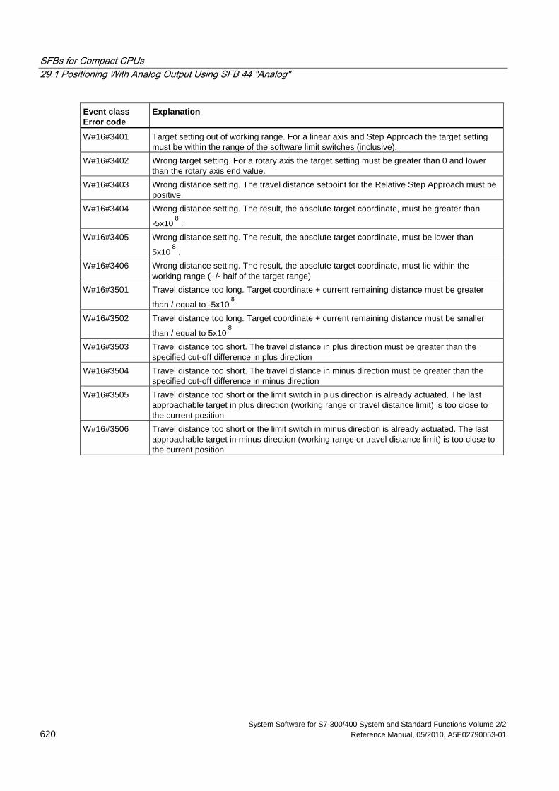
SFBs for Compact CPUs 29.1 Positioning With Analog Output Using SFB 44 "Analog"
System Software for S7-300/400 System and Standard Functions Volume 2/2 620 Reference Manual, 05/2010, A5E02790053-01
Event class Error code
Explanation
W#16#3401 Target setting out of working range. For a linear axis and Step Approach the target setting must be within the range of the software limit switches (inclusive).
W#16#3402 Wrong target setting. For a rotary axis the target setting must be greater than 0 and lower than the rotary axis end value.
W#16#3403 Wrong distance setting. The travel distance setpoint for the Relative Step Approach must be positive.
W#16#3404 Wrong distance setting. The result, the absolute target coordinate, must be greater than
-5x10⁸
. W#16#3405 Wrong distance setting. The result, the absolute target coordinate, must be lower than
5x10⁸
. W#16#3406 Wrong distance setting. The result, the absolute target coordinate, must lie within the
working range (+/- half of the target range) W#16#3501 Travel distance too long. Target coordinate + current remaining distance must be greater
than / equal to -5x10⁸
W#16#3502 Travel distance too long. Target coordinate + current remaining distance must be smaller
than / equal to 5x10⁸
W#16#3503 Travel distance too short. The travel distance in plus direction must be greater than the specified cut-off difference in plus direction
W#16#3504 Travel distance too short. The travel distance in minus direction must be greater than the specified cut-off difference in minus direction
W#16#3505 Travel distance too short or the limit switch in plus direction is already actuated. The last approachable target in plus direction (working range or travel distance limit) is too close to the current position
W#16#3506 Travel distance too short or the limit switch in minus direction is already actuated. The last approachable target in minus direction (working range or travel distance limit) is too close to the current position
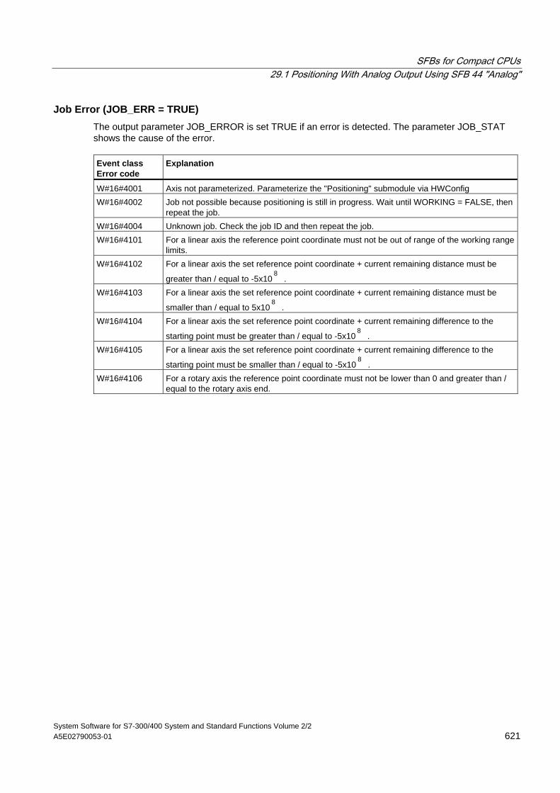
SFBs for Compact CPUs 29.1 Positioning With Analog Output Using SFB 44 "Analog"
System Software for S7-300/400 System and Standard Functions Volume 2/2 A5E02790053-01 621
Job Error (JOB_ERR = TRUE) The output parameter JOB_ERROR is set TRUE if an error is detected. The parameter JOB_STAT shows the cause of the error. Event class Error code
Explanation
W#16#4001 Axis not parameterized. Parameterize the "Positioning" submodule via HWConfig W#16#4002 Job not possible because positioning is still in progress. Wait until WORKING = FALSE, then
repeat the job. W#16#4004 Unknown job. Check the job ID and then repeat the job. W#16#4101 For a linear axis the reference point coordinate must not be out of range of the working range
limits. W#16#4102 For a linear axis the set reference point coordinate + current remaining distance must be
greater than / equal to -5x10⁸
. W#16#4103 For a linear axis the set reference point coordinate + current remaining distance must be
smaller than / equal to 5x10⁸
. W#16#4104 For a linear axis the set reference point coordinate + current remaining difference to the
starting point must be greater than / equal to -5x10⁸
. W#16#4105 For a linear axis the set reference point coordinate + current remaining difference to the
starting point must be smaller than / equal to -5x10⁸
. W#16#4106 For a rotary axis the reference point coordinate must not be lower than 0 and greater than /
equal to the rotary axis end.
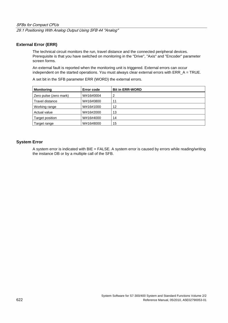
SFBs for Compact CPUs 29.1 Positioning With Analog Output Using SFB 44 "Analog"
System Software for S7-300/400 System and Standard Functions Volume 2/2 622 Reference Manual, 05/2010, A5E02790053-01
External Error (ERR) The technical circuit monitors the run, travel distance and the connected peripheral devices. Prerequisite is that you have switched on monitoring in the "Drive", "Axis" and "Encoder" parameter screen forms.
An external fault is reported when the monitoring unit is triggered. External errors can occur independent on the started operations. You must always clear external errors with ERR_A = TRUE.
A set bit in the SFB parameter ERR (WORD) the external errors. Monitoring Error code Bit in ERR-WORD
Zero pulse (zero mark) W#16#0004 2 Travel distance W#16#0800 11 Working range W#16#1000 12 Actual value W#16#2000 13 Target position W#16#4000 14 Target range W#16#8000 15
System Error A system error is indicated with BIE = FALSE. A system error is caused by errors while reading/writing the instance DB or by a multiple call of the SFB.
SFBs for Compact CPUs 29.2 Positioning with Digital Output Using SFB 46 "DIGITAL"
System Software for S7-300/400 System and Standard Functions Volume 2/2 A5E02790053-01 623
29.2 Positioning with Digital Output Using SFB 46 "DIGITAL"
Description Use SFB DIGITAL (SFB 46) to control the positioning functions via user program.
The four 24-V digital outputs are assigned fixed to drive. They control the power stage. Dependent on the control mode configuration, the digital outputs control the direction and speed stages (rapid/creep speed).
The distance is measured via an asymmetrical 24-V incremental transducer with two phases offset at 90 degrees.
• First, the target is approached with the speed (VRapid).
• At the changeover point the speed is toggled to creep speed (VCreep).
• The drive is switched off at the switch-off point.
• The switch-over point and the switch-off point are determined for every Step Approach by the parameter values you have declared for changeover difference and cut-off difference. The changeover difference and cut-off difference can be determined differently for the forward motion (in plus direction) and for the reverse motion (in minus direction).
• The run is completed (WORKING = FALSE) when the cut-off point is reached. A new run can then be started.
• The specified target is reached (POS_RCD = TRUE) when the current position value has reached the home target. If the current position value drifts off without a new run having been started the signal "Position reached" is not reset again.
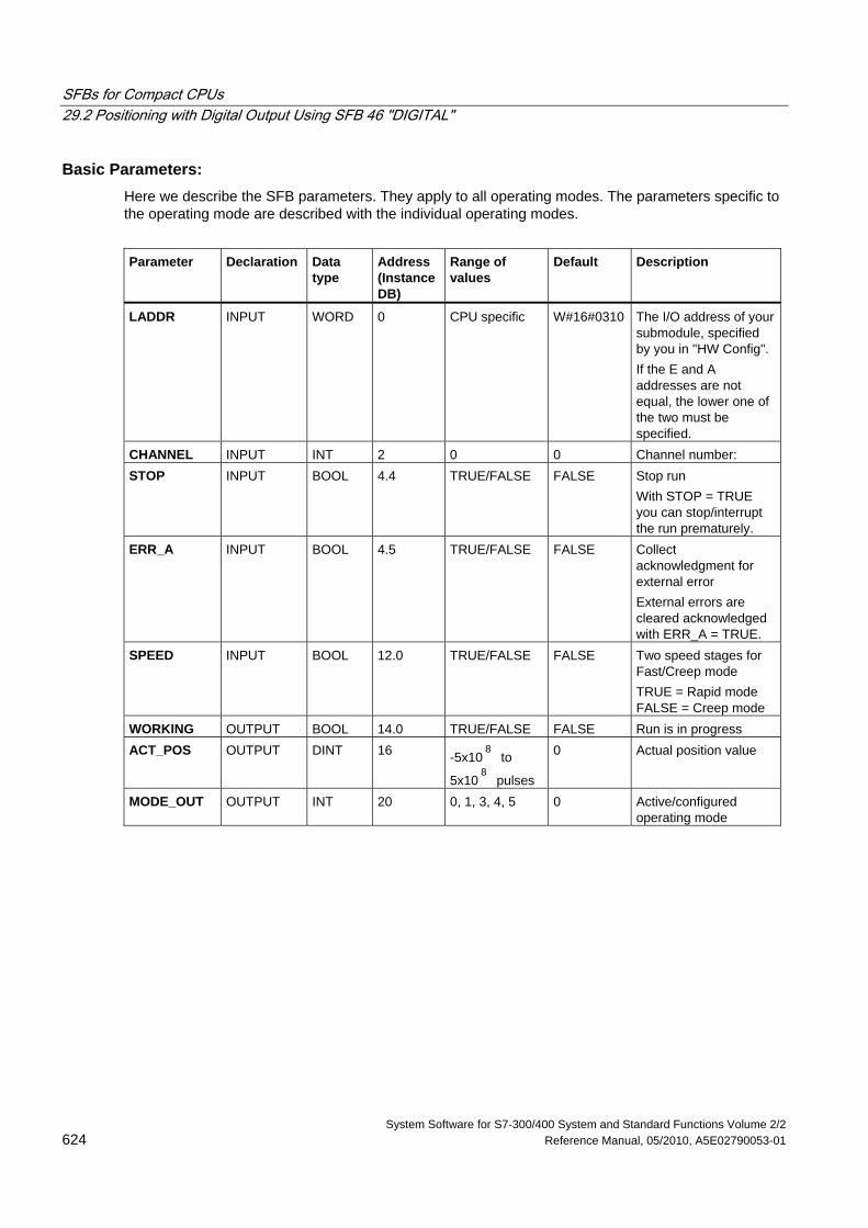
SFBs for Compact CPUs 29.2 Positioning with Digital Output Using SFB 46 "DIGITAL"
System Software for S7-300/400 System and Standard Functions Volume 2/2 624 Reference Manual, 05/2010, A5E02790053-01
Basic Parameters: Here we describe the SFB parameters. They apply to all operating modes. The parameters specific to the operating mode are described with the individual operating modes.
Parameter Declaration Data
type Address (Instance DB)
Range of values
Default Description
LADDR INPUT WORD 0 CPU specific W#16#0310 The I/O address of your submodule, specified by you in "HW Config". If the E and A addresses are not equal, the lower one of the two must be specified.
CHANNEL INPUT INT 2 0 0 Channel number: STOP INPUT BOOL 4.4 TRUE/FALSE FALSE Stop run
With STOP = TRUE you can stop/interrupt the run prematurely.
ERR_A INPUT BOOL 4.5 TRUE/FALSE FALSE Collect acknowledgment for external error External errors are cleared acknowledged with ERR_A = TRUE.
SPEED INPUT BOOL 12.0 TRUE/FALSE FALSE Two speed stages for Fast/Creep mode TRUE = Rapid mode FALSE = Creep mode
WORKING OUTPUT BOOL 14.0 TRUE/FALSE FALSE Run is in progress ACT_POS OUTPUT DINT 16 -5x10
8 to
5x10⁸
pulses
0 Actual position value
MODE_OUT OUTPUT INT 20 0, 1, 3, 4, 5 0 Active/configured operating mode
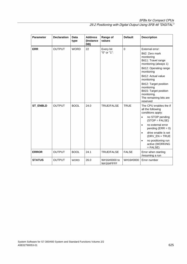
SFBs for Compact CPUs 29.2 Positioning with Digital Output Using SFB 46 "DIGITAL"
System Software for S7-300/400 System and Standard Functions Volume 2/2 A5E02790053-01 625
Parameter Declaration Data type
Address (Instance DB)
Range of values
Default Description
ERR OUTPUT WORD 22 Every bit "0" or "1":
0 External error: Bit2: Zero mark monitoring Bit11: Travel range monitoring (always 1) Bit12: Operating range monitoring Bit12: Actual value monitoring Bit12: Target position monitoring Bit15: Target position monitoring. The remaining bits are reserved
ST_ENBLD OUTPUT BOOL 24.0 TRUE/FALSE TRUE The CPU enables the if all the following conditions apply: • no STOP pending
(STOP = FALSE) • no external error
pending (ERR = 0) • drive enable is set
(DRV_EN = TRUE • no positioning run
active (WORKING = FALSE)
ERROR OUTPUT BOOL 24.1 TRUE/FALSE FALSE Error when starting /resuming a run
STATUS OUTPUT WORD 26.0 W#16#0000 to W#16#FFFF
W#16#0000 Error number
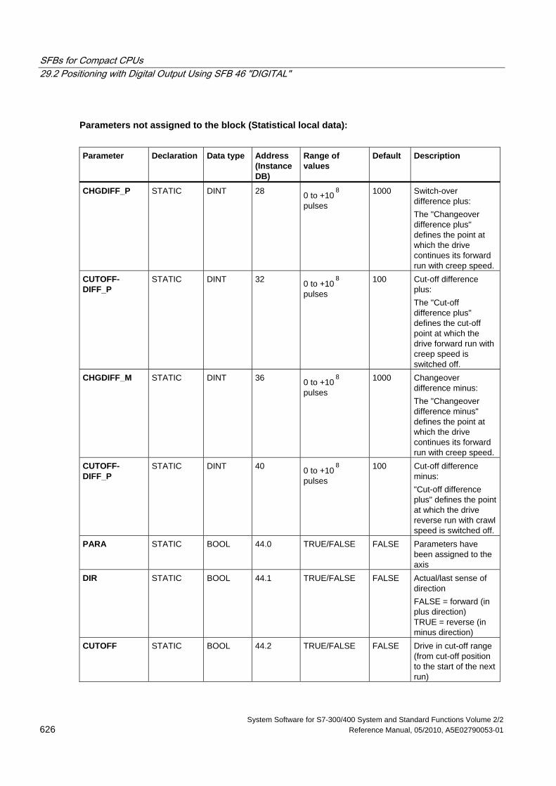
SFBs for Compact CPUs 29.2 Positioning with Digital Output Using SFB 46 "DIGITAL"
System Software for S7-300/400 System and Standard Functions Volume 2/2 626 Reference Manual, 05/2010, A5E02790053-01
Parameters not assigned to the block (Statistical local data):
Parameter Declaration Data type Address
(Instance DB)
Range of values
Default Description
CHGDIFF_P STATIC DINT 28 0 to +108
pulses
1000 Switch-over difference plus: The "Changeover difference plus" defines the point at which the drive continues its forward run with creep speed.
CUTOFF- DIFF_P
STATIC DINT 32 0 to +108
pulses
100 Cut-off difference plus: The "Cut-off difference plus" defines the cut-off point at which the drive forward run with creep speed is switched off.
CHGDIFF_M STATIC DINT 36 0 to +108
pulses
1000 Changeover difference minus: The "Changeover difference minus" defines the point at which the drive continues its forward run with creep speed.
CUTOFF- DIFF_P
STATIC DINT 40 0 to +108
pulses
100 Cut-off difference minus: "Cut-off difference plus" defines the point at which the drive reverse run with crawl speed is switched off.
PARA STATIC BOOL 44.0 TRUE/FALSE FALSE Parameters have been assigned to the axis
DIR STATIC BOOL 44.1 TRUE/FALSE FALSE Actual/last sense of direction FALSE = forward (in plus direction) TRUE = reverse (in minus direction)
CUTOFF STATIC BOOL 44.2 TRUE/FALSE FALSE Drive in cut-off range (from cut-off position to the start of the next run)
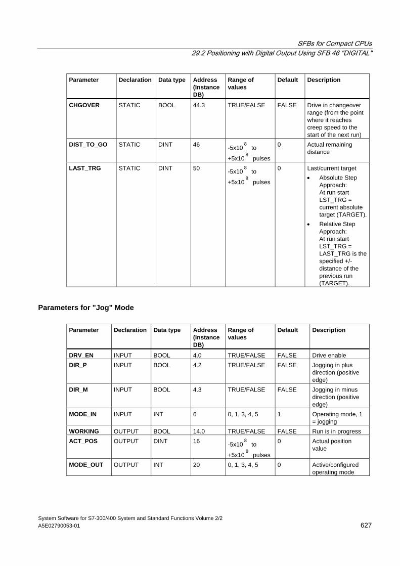
SFBs for Compact CPUs 29.2 Positioning with Digital Output Using SFB 46 "DIGITAL"
System Software for S7-300/400 System and Standard Functions Volume 2/2 A5E02790053-01 627
Parameter Declaration Data type Address (Instance DB)
Range of values
Default Description
CHGOVER STATIC BOOL 44.3 TRUE/FALSE FALSE Drive in changeover range (from the point where it reaches creep speed to the start of the next run)
DIST_TO_GO STATIC DINT 46 -5x10⁸
to
+5x10⁸
pulses
0 Actual remaining distance
LAST_TRG STATIC DINT 50 -5x10⁸
to
+5x10⁸
pulses
0 Last/current target • Absolute Step
Approach: At run start LST_TRG = current absolute target (TARGET).
• Relative Step Approach: At run start LST_TRG = LAST_TRG is the specified +/- distance of the previous run (TARGET).
Parameters for "Jog" Mode Parameter Declaration Data type Address
(Instance DB)
Range of values
Default Description
DRV_EN INPUT BOOL 4.0 TRUE/FALSE FALSE Drive enable DIR_P INPUT BOOL 4.2 TRUE/FALSE FALSE Jogging in plus
direction (positive edge)
DIR_M INPUT BOOL 4.3 TRUE/FALSE FALSE Jogging in minus direction (positive edge)
MODE_IN INPUT INT 6 0, 1, 3, 4, 5 1 Operating mode, 1 = jogging
WORKING OUTPUT BOOL 14.0 TRUE/FALSE FALSE Run is in progress ACT_POS OUTPUT DINT 16 -5x10
8 to
+5x10⁸
pulses
0 Actual position value
MODE_OUT OUTPUT INT 20 0, 1, 3, 4, 5 0 Active/configured operating mode
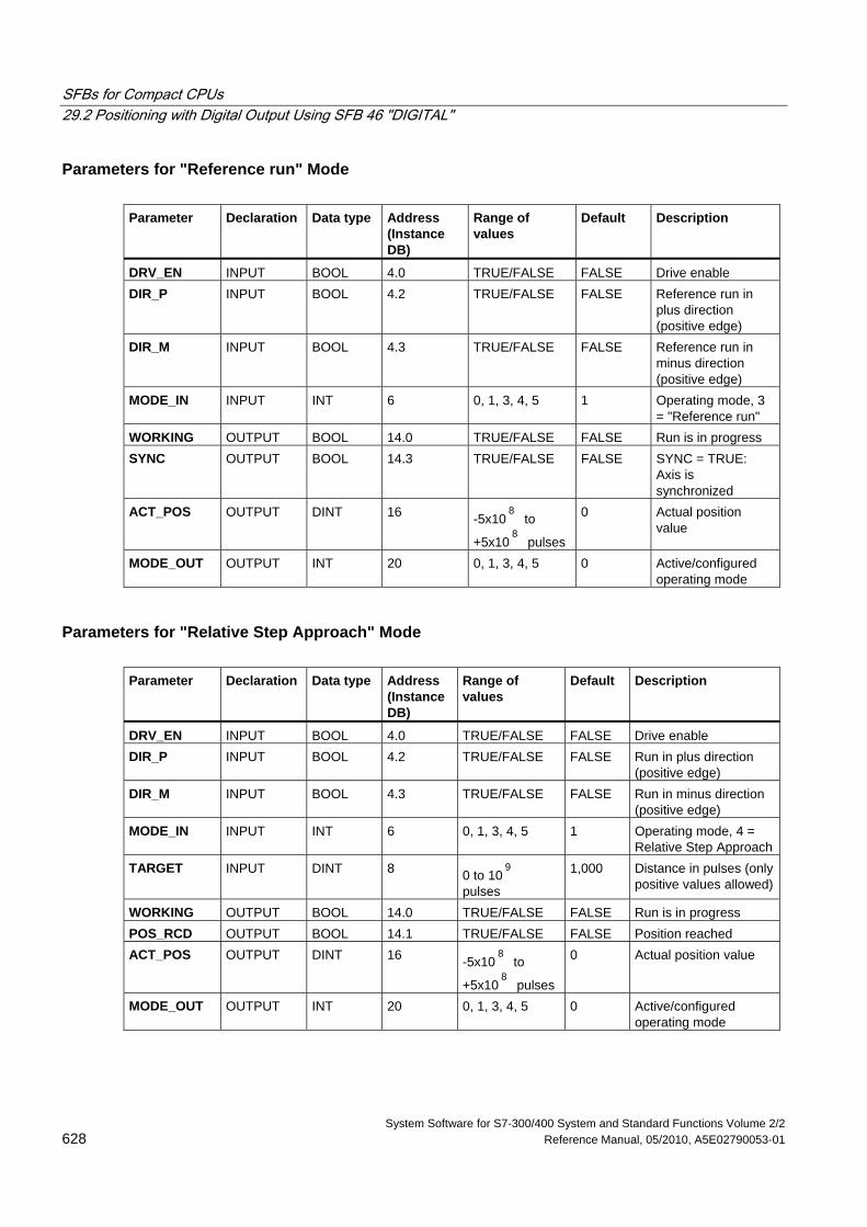
SFBs for Compact CPUs 29.2 Positioning with Digital Output Using SFB 46 "DIGITAL"
System Software for S7-300/400 System and Standard Functions Volume 2/2 628 Reference Manual, 05/2010, A5E02790053-01
Parameters for "Reference run" Mode Parameter Declaration Data type Address
(Instance DB)
Range of values
Default Description
DRV_EN INPUT BOOL 4.0 TRUE/FALSE FALSE Drive enable DIR_P INPUT BOOL 4.2 TRUE/FALSE FALSE Reference run in
plus direction (positive edge)
DIR_M INPUT BOOL 4.3 TRUE/FALSE FALSE Reference run in minus direction (positive edge)
MODE_IN INPUT INT 6 0, 1, 3, 4, 5 1 Operating mode, 3 = "Reference run"
WORKING OUTPUT BOOL 14.0 TRUE/FALSE FALSE Run is in progress SYNC OUTPUT BOOL 14.3 TRUE/FALSE FALSE SYNC = TRUE:
Axis is synchronized
ACT_POS OUTPUT DINT 16 -5x10⁸
to
+5x10⁸
pulses
0 Actual position value
MODE_OUT OUTPUT INT 20 0, 1, 3, 4, 5 0 Active/configured operating mode
Parameters for "Relative Step Approach" Mode Parameter Declaration Data type Address
(Instance DB)
Range of values
Default Description
DRV_EN INPUT BOOL 4.0 TRUE/FALSE FALSE Drive enable DIR_P INPUT BOOL 4.2 TRUE/FALSE FALSE Run in plus direction
(positive edge) DIR_M INPUT BOOL 4.3 TRUE/FALSE FALSE Run in minus direction
(positive edge) MODE_IN INPUT INT 6 0, 1, 3, 4, 5 1 Operating mode, 4 =
Relative Step ApproachTARGET INPUT DINT 8 0 to 10
9
pulses
1,000 Distance in pulses (only positive values allowed)
WORKING OUTPUT BOOL 14.0 TRUE/FALSE FALSE Run is in progress POS_RCD OUTPUT BOOL 14.1 TRUE/FALSE FALSE Position reached ACT_POS OUTPUT DINT 16 -5x10
8 to
+5x10⁸
pulses
0 Actual position value
MODE_OUT OUTPUT INT 20 0, 1, 3, 4, 5 0 Active/configured operating mode
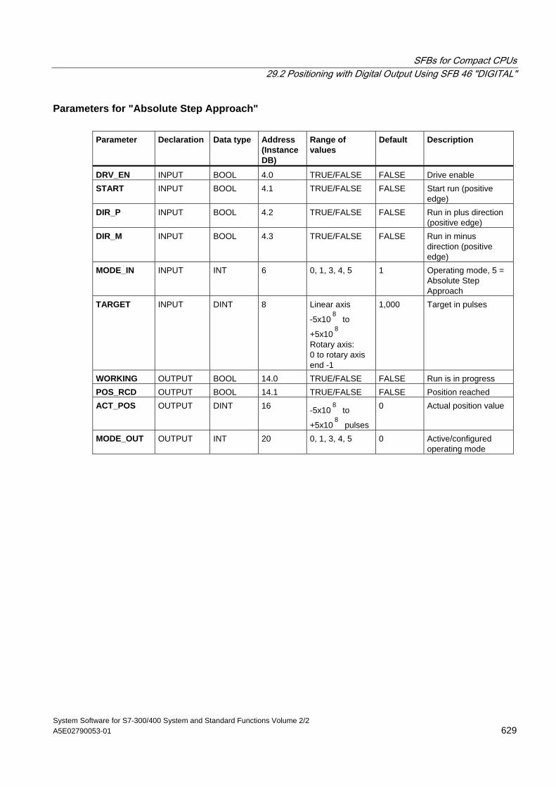
SFBs for Compact CPUs 29.2 Positioning with Digital Output Using SFB 46 "DIGITAL"
System Software for S7-300/400 System and Standard Functions Volume 2/2 A5E02790053-01 629
Parameters for "Absolute Step Approach" Parameter Declaration Data type Address
(Instance DB)
Range of values
Default Description
DRV_EN INPUT BOOL 4.0 TRUE/FALSE FALSE Drive enable START INPUT BOOL 4.1 TRUE/FALSE FALSE Start run (positive
edge) DIR_P INPUT BOOL 4.2 TRUE/FALSE FALSE Run in plus direction
(positive edge) DIR_M INPUT BOOL 4.3 TRUE/FALSE FALSE Run in minus
direction (positive edge)
MODE_IN INPUT INT 6 0, 1, 3, 4, 5 1 Operating mode, 5 = Absolute Step Approach
TARGET INPUT DINT 8 Linear axis
-5x10⁸
to
+5x10⁸
Rotary axis: 0 to rotary axis end -1
1,000 Target in pulses
WORKING OUTPUT BOOL 14.0 TRUE/FALSE FALSE Run is in progress POS_RCD OUTPUT BOOL 14.1 TRUE/FALSE FALSE Position reached ACT_POS OUTPUT DINT 16 -5x10
8 to
+5x10⁸
pulses
0 Actual position value
MODE_OUT OUTPUT INT 20 0, 1, 3, 4, 5 0 Active/configured operating mode
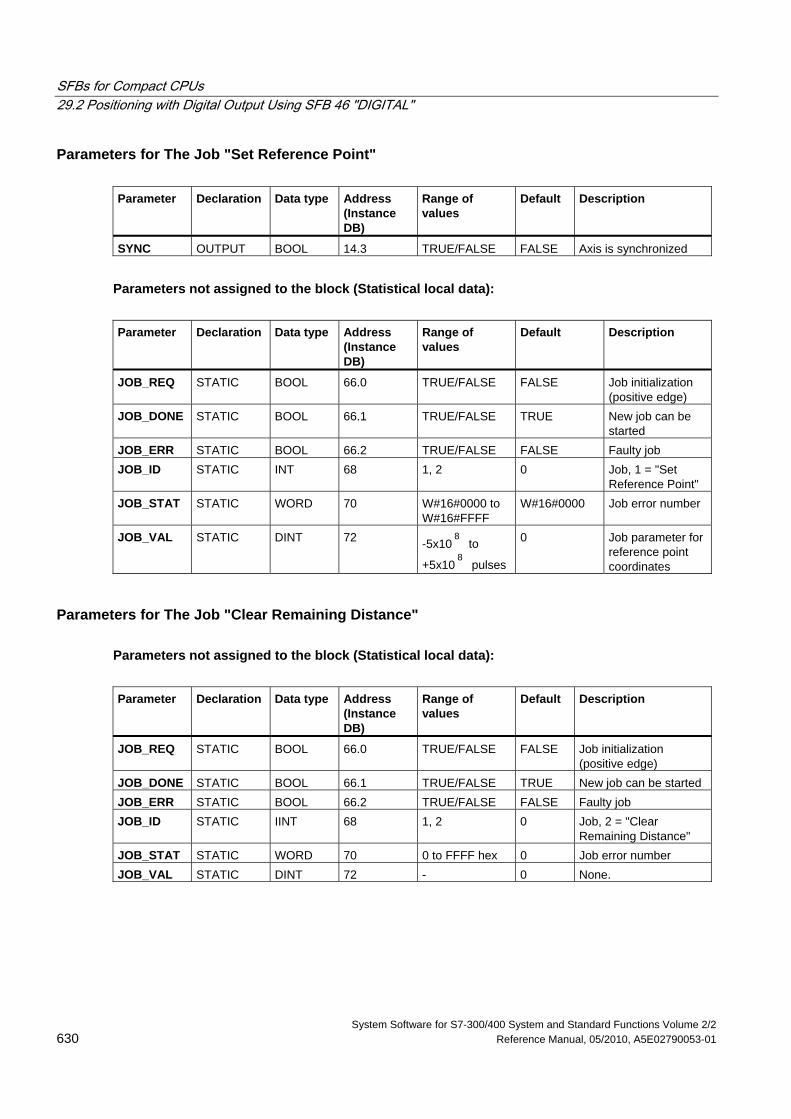
SFBs for Compact CPUs 29.2 Positioning with Digital Output Using SFB 46 "DIGITAL"
System Software for S7-300/400 System and Standard Functions Volume 2/2 630 Reference Manual, 05/2010, A5E02790053-01
Parameters for The Job "Set Reference Point" Parameter Declaration Data type Address
(Instance DB)
Range of values
Default Description
SYNC OUTPUT BOOL 14.3 TRUE/FALSE FALSE Axis is synchronized
Parameters not assigned to the block (Statistical local data):
Parameter Declaration Data type Address
(Instance DB)
Range of values
Default Description
JOB_REQ STATIC BOOL 66.0 TRUE/FALSE FALSE Job initialization (positive edge)
JOB_DONE STATIC BOOL 66.1 TRUE/FALSE TRUE New job can be started
JOB_ERR STATIC BOOL 66.2 TRUE/FALSE FALSE Faulty job JOB_ID STATIC INT 68 1, 2 0 Job, 1 = "Set
Reference Point" JOB_STAT STATIC WORD 70 W#16#0000 to
W#16#FFFF W#16#0000 Job error number
JOB_VAL STATIC DINT 72 -5x10⁸
to
+5x10⁸
pulses
0 Job parameter for reference point coordinates
Parameters for The Job "Clear Remaining Distance" Parameters not assigned to the block (Statistical local data):
Parameter Declaration Data type Address
(Instance DB)
Range of values
Default Description
JOB_REQ STATIC BOOL 66.0 TRUE/FALSE FALSE Job initialization (positive edge)
JOB_DONE STATIC BOOL 66.1 TRUE/FALSE TRUE New job can be started JOB_ERR STATIC BOOL 66.2 TRUE/FALSE FALSE Faulty job JOB_ID STATIC IINT 68 1, 2 0 Job, 2 = "Clear
Remaining Distance" JOB_STAT STATIC WORD 70 0 to FFFF hex 0 Job error number JOB_VAL STATIC DINT 72 - 0 None.
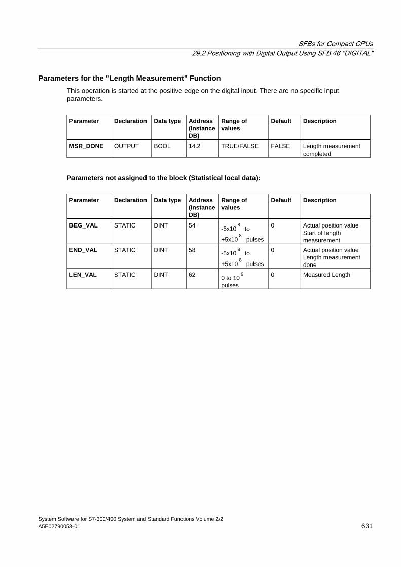
SFBs for Compact CPUs 29.2 Positioning with Digital Output Using SFB 46 "DIGITAL"
System Software for S7-300/400 System and Standard Functions Volume 2/2 A5E02790053-01 631
Parameters for the "Length Measurement" Function This operation is started at the positive edge on the digital input. There are no specific input parameters.
Parameter Declaration Data type Address
(Instance DB)
Range of values
Default Description
MSR_DONE OUTPUT BOOL 14.2 TRUE/FALSE FALSE Length measurement completed
Parameters not assigned to the block (Statistical local data):
Parameter Declaration Data type Address
(Instance DB)
Range of values
Default Description
BEG_VAL STATIC DINT 54 -5x10⁸
to
+5x10⁸
pulses
0 Actual position value Start of length measurement
END_VAL STATIC DINT 58 -5x10⁸
to
+5x10⁸
pulses
0 Actual position value Length measurement done
LEN_VAL STATIC DINT 62 0 to 109
pulses
0 Measured Length
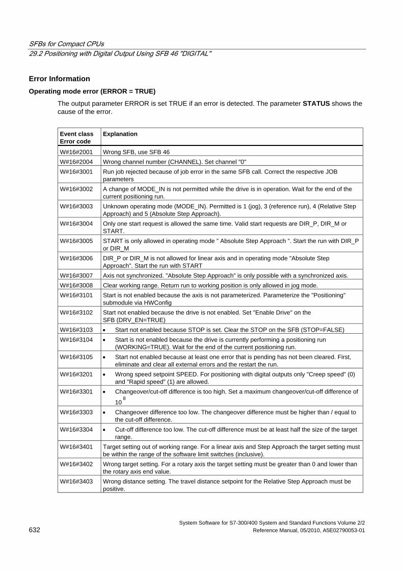
SFBs for Compact CPUs 29.2 Positioning with Digital Output Using SFB 46 "DIGITAL"
System Software for S7-300/400 System and Standard Functions Volume 2/2 632 Reference Manual, 05/2010, A5E02790053-01
Error Information Operating mode error (ERROR = TRUE)
The output parameter ERROR is set TRUE if an error is detected. The parameter STATUS shows the cause of the error.
Event class Error code
Explanation
W#16#2001 Wrong SFB, use SFB 46 W#16#2004 Wrong channel number (CHANNEL). Set channel "0" W#16#3001 Run job rejected because of job error in the same SFB call. Correct the respective JOB
parameters W#16#3002 A change of MODE_IN is not permitted while the drive is in operation. Wait for the end of the
current positioning run. W#16#3003 Unknown operating mode (MODE_IN). Permitted is 1 (jog), 3 (reference run), 4 (Relative Step
Approach) and 5 (Absolute Step Approach). W#16#3004 Only one start request is allowed the same time. Valid start requests are DIR_P, DIR_M or
START. W#16#3005 START is only allowed in operating mode ” Absolute Step Approach ”. Start the run with DIR_P
or DIR_M W#16#3006 DIR_P or DIR_M is not allowed for linear axis and in operating mode "Absolute Step
Approach". Start the run with START W#16#3007 Axis not synchronized. "Absolute Step Approach" is only possible with a synchronized axis. W#16#3008 Clear working range. Return run to working position is only allowed in jog mode. W#16#3101 Start is not enabled because the axis is not parameterized. Parameterize the "Positioning"
submodule via HWConfig W#16#3102 Start not enabled because the drive is not enabled. Set "Enable Drive" on the
SFB (DRV_EN=TRUE) W#16#3103 • Start not enabled because STOP is set. Clear the STOP on the SFB (STOP=FALSE) W#16#3104 • Start is not enabled because the drive is currently performing a positioning run
(WORKING=TRUE). Wait for the end of the current positioning run. W#16#3105 • Start not enabled because at least one error that is pending has not been cleared. First,
eliminate and clear all external errors and the restart the run. W#16#3201 • Wrong speed setpoint SPEED. For positioning with digital outputs only "Creep speed" (0)
and "Rapid speed" (1) are allowed. W#16#3301 • Changeover/cut-off difference is too high. Set a maximum changeover/cut-off difference of
108
W#16#3303 • Changeover difference too low. The changeover difference must be higher than / equal to
the cut-off difference. W#16#3304 • Cut-off difference too low. The cut-off difference must be at least half the size of the target
range. W#16#3401 Target setting out of working range. For a linear axis and Step Approach the target setting must
be within the range of the software limit switches (inclusive). W#16#3402 Wrong target setting. For a rotary axis the target setting must be greater than 0 and lower than
the rotary axis end value. W#16#3403 Wrong distance setting. The travel distance setpoint for the Relative Step Approach must be
positive.
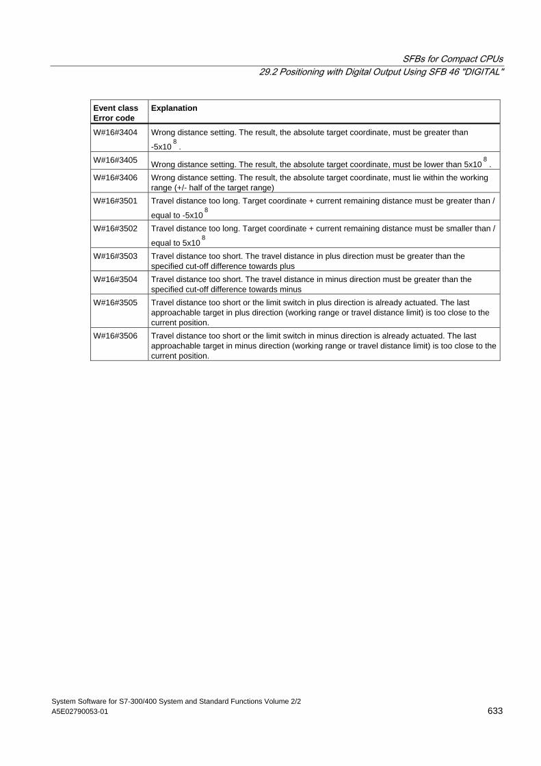
SFBs for Compact CPUs 29.2 Positioning with Digital Output Using SFB 46 "DIGITAL"
System Software for S7-300/400 System and Standard Functions Volume 2/2 A5E02790053-01 633
Event class Error code
Explanation
W#16#3404 Wrong distance setting. The result, the absolute target coordinate, must be greater than
-5x10⁸
. W#16#3405 Wrong distance setting. The result, the absolute target coordinate, must be lower than 5x10
8.
W#16#3406 Wrong distance setting. The result, the absolute target coordinate, must lie within the working range (+/- half of the target range)
W#16#3501 Travel distance too long. Target coordinate + current remaining distance must be greater than /
equal to -5x10⁸
W#16#3502 Travel distance too long. Target coordinate + current remaining distance must be smaller than /
equal to 5x10⁸
W#16#3503 Travel distance too short. The travel distance in plus direction must be greater than the specified cut-off difference towards plus
W#16#3504 Travel distance too short. The travel distance in minus direction must be greater than the specified cut-off difference towards minus
W#16#3505 Travel distance too short or the limit switch in plus direction is already actuated. The last approachable target in plus direction (working range or travel distance limit) is too close to the current position.
W#16#3506 Travel distance too short or the limit switch in minus direction is already actuated. The last approachable target in minus direction (working range or travel distance limit) is too close to the current position.
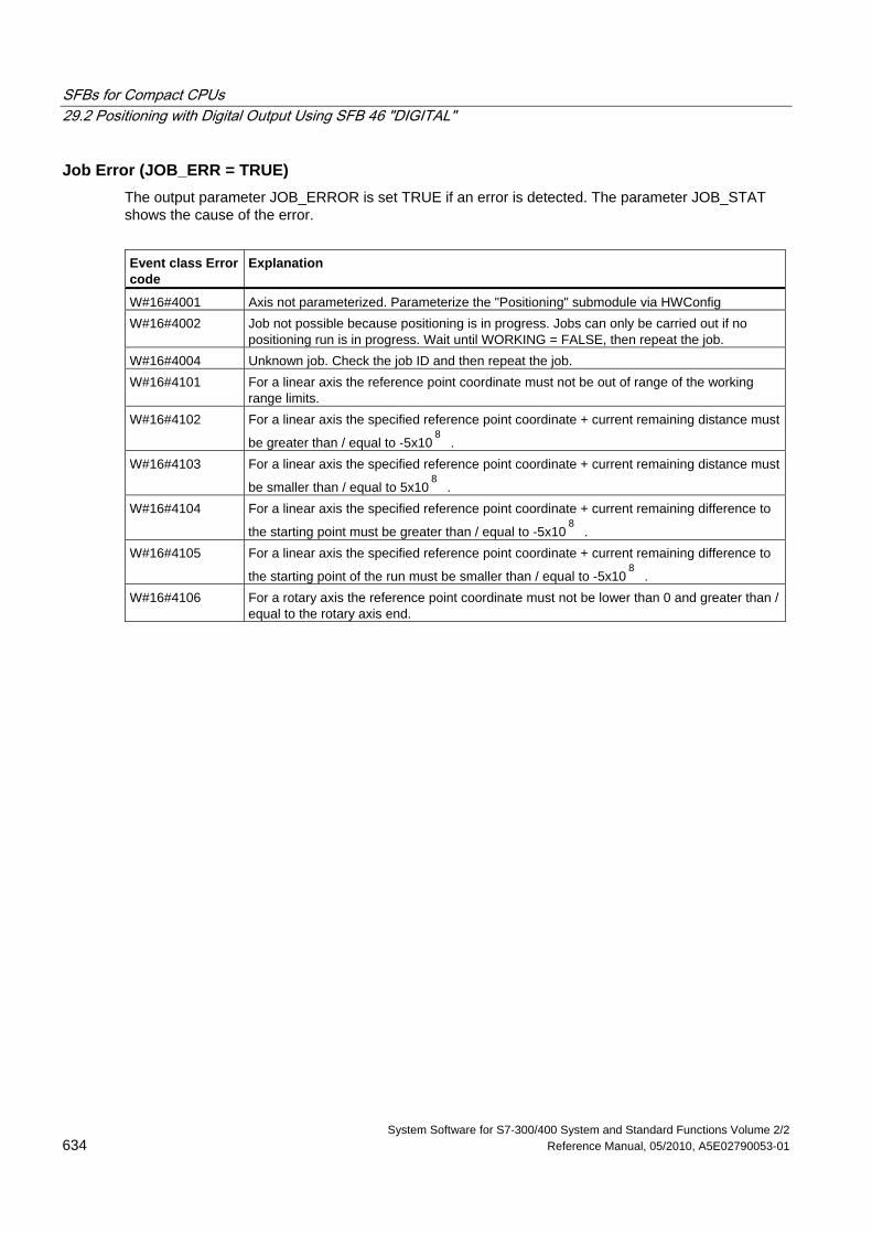
SFBs for Compact CPUs 29.2 Positioning with Digital Output Using SFB 46 "DIGITAL"
System Software for S7-300/400 System and Standard Functions Volume 2/2 634 Reference Manual, 05/2010, A5E02790053-01
Job Error (JOB_ERR = TRUE) The output parameter JOB_ERROR is set TRUE if an error is detected. The parameter JOB_STAT shows the cause of the error.
Event class Error code
Explanation
W#16#4001 Axis not parameterized. Parameterize the "Positioning" submodule via HWConfig W#16#4002 Job not possible because positioning is in progress. Jobs can only be carried out if no
positioning run is in progress. Wait until WORKING = FALSE, then repeat the job. W#16#4004 Unknown job. Check the job ID and then repeat the job. W#16#4101 For a linear axis the reference point coordinate must not be out of range of the working
range limits. W#16#4102 For a linear axis the specified reference point coordinate + current remaining distance must
be greater than / equal to -5x10⁸
. W#16#4103 For a linear axis the specified reference point coordinate + current remaining distance must
be smaller than / equal to 5x10⁸
. W#16#4104 For a linear axis the specified reference point coordinate + current remaining difference to
the starting point must be greater than / equal to -5x10⁸
. W#16#4105 For a linear axis the specified reference point coordinate + current remaining difference to
the starting point of the run must be smaller than / equal to -5x10⁸
. W#16#4106 For a rotary axis the reference point coordinate must not be lower than 0 and greater than /
equal to the rotary axis end.
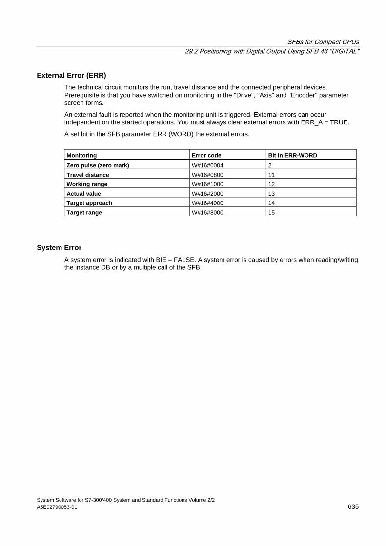
SFBs for Compact CPUs 29.2 Positioning with Digital Output Using SFB 46 "DIGITAL"
System Software for S7-300/400 System and Standard Functions Volume 2/2 A5E02790053-01 635
External Error (ERR) The technical circuit monitors the run, travel distance and the connected peripheral devices. Prerequisite is that you have switched on monitoring in the "Drive", "Axis" and "Encoder" parameter screen forms.
An external fault is reported when the monitoring unit is triggered. External errors can occur independent on the started operations. You must always clear external errors with ERR_A = TRUE.
A set bit in the SFB parameter ERR (WORD) the external errors.
Monitoring Error code Bit in ERR-WORD
Zero pulse (zero mark) W#16#0004 2 Travel distance W#16#0800 11 Working range W#16#1000 12 Actual value W#16#2000 13 Target approach W#16#4000 14 Target range W#16#8000 15
System Error A system error is indicated with BIE = FALSE. A system error is caused by errors when reading/writing the instance DB or by a multiple call of the SFB.
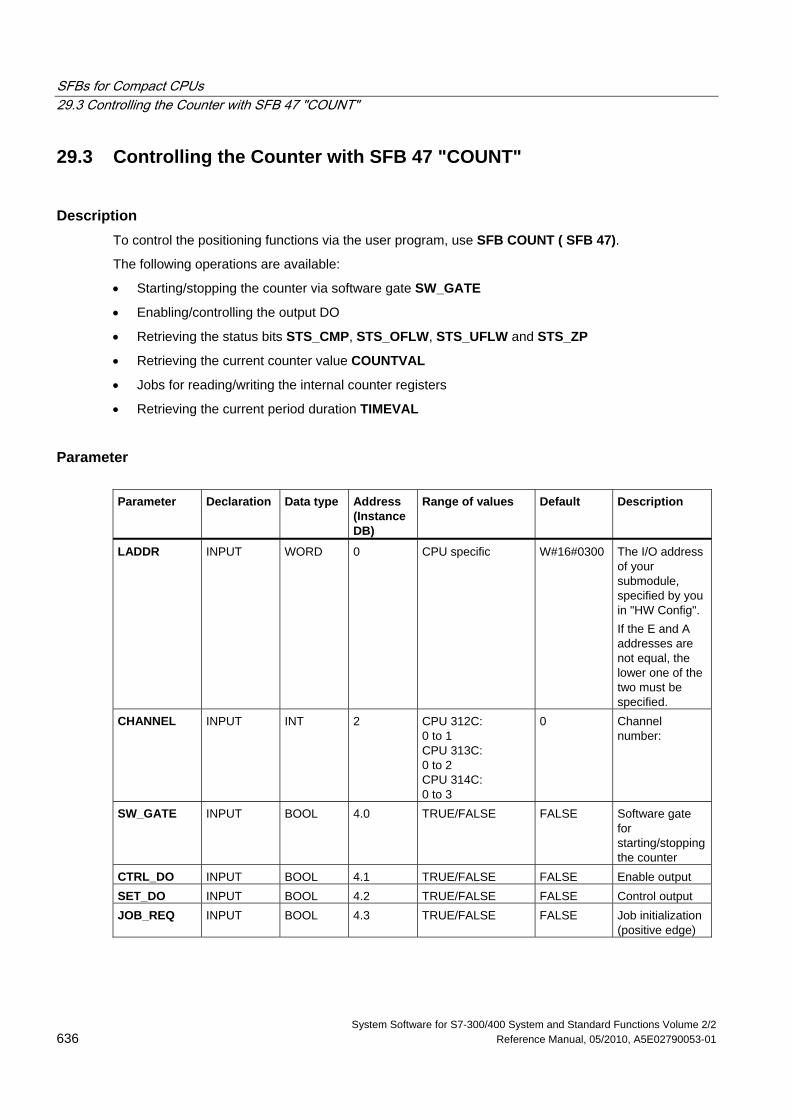
SFBs for Compact CPUs 29.3 Controlling the Counter with SFB 47 "COUNT"
System Software for S7-300/400 System and Standard Functions Volume 2/2 636 Reference Manual, 05/2010, A5E02790053-01
29.3 Controlling the Counter with SFB 47 "COUNT"
Description To control the positioning functions via the user program, use SFB COUNT ( SFB 47).
The following operations are available:
• Starting/stopping the counter via software gate SW_GATE
• Enabling/controlling the output DO
• Retrieving the status bits STS_CMP, STS_OFLW, STS_UFLW and STS_ZP
• Retrieving the current counter value COUNTVAL
• Jobs for reading/writing the internal counter registers
• Retrieving the current period duration TIMEVAL
Parameter Parameter Declaration Data type Address
(Instance DB)
Range of values Default Description
LADDR INPUT WORD 0 CPU specific W#16#0300 The I/O address of your submodule, specified by you in "HW Config". If the E and A addresses are not equal, the lower one of the two must be specified.
CHANNEL INPUT INT 2
CPU 312C: 0 to 1 CPU 313C: 0 to 2 CPU 314C: 0 to 3
0 Channel number:
SW_GATE INPUT BOOL 4.0 TRUE/FALSE FALSE Software gate for starting/stopping the counter
CTRL_DO INPUT BOOL 4.1 TRUE/FALSE FALSE Enable output SET_DO INPUT BOOL 4.2 TRUE/FALSE FALSE Control output JOB_REQ INPUT BOOL 4.3 TRUE/FALSE FALSE Job initialization
(positive edge)
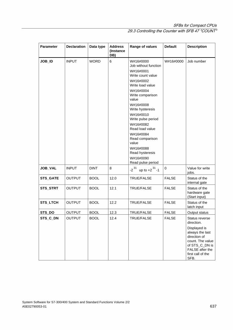
SFBs for Compact CPUs 29.3 Controlling the Counter with SFB 47 "COUNT"
System Software for S7-300/400 System and Standard Functions Volume 2/2 A5E02790053-01 637
Parameter Declaration Data type Address (Instance DB)
Range of values Default Description
JOB_ID INPUT WORD 6 W#16#0000 Job without function W#16#0001 Write count value W#16#0002 Write load value W#16#0004 Write comparison value W#16#0008 Write hysteresis W#16#0010 Write pulse period W#16#0082 Read load value W#16#0084 Read comparison value W#16#0088 Read hysteresis W#16#0090 Read pulse period
W#16#0000 Job number
JOB_VAL INPUT DINT 8 -231
up to +231
-1 0 Value for write jobs.
STS_GATE OUTPUT BOOL 12.0 TRUE/FALSE FALSE Status of the internal gate
STS_STRT OUTPUT BOOL 12.1 TRUE/FALSE FALSE Status of the hardware gate (Start input)
STS_LTCH OUTPUT BOOL 12.2 TRUE/FALSE FALSE Status of the latch input
STS_DO OUTPUT BOOL 12.3 TRUE/FALSE FALSE Output status STS_C_DN OUTPUT BOOL 12.4 TRUE/FALSE FALSE Status reverse
direction. Displayed is always the last direction of count. The value of STS_C_DN is FALSE after the first call of the SFB.
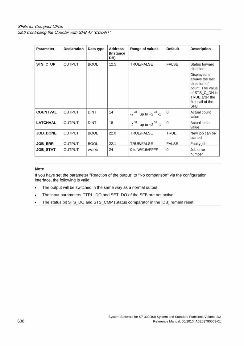
SFBs for Compact CPUs 29.3 Controlling the Counter with SFB 47 "COUNT"
System Software for S7-300/400 System and Standard Functions Volume 2/2 638 Reference Manual, 05/2010, A5E02790053-01
Parameter Declaration Data type Address (Instance DB)
Range of values Default Description
STS_C_UP OUTPUT BOOL 12.5 TRUE/FALSE FALSE Status forward direction Displayed is always the last direction of count. The value of STS_C_DN is TRUE after the first call of the SFB.
COUNTVAL OUTPUT DINT 14 -231
up to +231
-1 0 Actual count value
LATCHVAL OUTPUT DINT 18 -231
up to +231
-1 0 Actual latch value
JOB_DONE OUTPUT BOOL 22.0 TRUE/FALSE TRUE New job can be started
JOB_ERR OUTPUT BOOL 22.1 TRUE/FALSE FALSE Faulty job JOB_STAT OUTPUT WORD 24 0 to W#16#FFFF 0 Job error
number
Note
If you have set the parameter "Reaction of the output" to "No comparison" via the configuration interface, the following is valid:
• The output will be switched in the same way as a normal output.
• The input parameters CTRL_DO and SET_DO of the SFB are not active.
• The status bit STS_DO and STS_CMP (Status comparator in the IDB) remain reset.
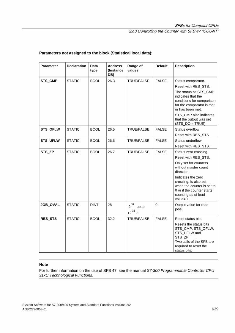
SFBs for Compact CPUs 29.3 Controlling the Counter with SFB 47 "COUNT"
System Software for S7-300/400 System and Standard Functions Volume 2/2 A5E02790053-01 639
Parameters not assigned to the block (Statistical local data):
Parameter Declaration Data
type Address (Instance DB)
Range of values
Default Description
STS_CMP STATIC BOOL 26.3 TRUE/FALSE FALSE Status comparator. Reset with RES_STS. The status bit STS_CMP indicates that the conditions for comparison for the comparator is met or has been met. STS_CMP also indicates that the output was set (STS_DO = TRUE)
STS_OFLW STATIC BOOL 26.5 TRUE/FALSE FALSE Status overflow Reset with RES_STS.
STS_UFLW STATIC BOOL 26.6 TRUE/FALSE FALSE Status underflow Reset with RES_STS.
STS_ZP STATIC BOOL 26.7 TRUE/FALSE FALSE Status zero crossing Reset with RES_STS. Only set for counters without master count direction. Indicates the zero crossing. Is also set when the counter is set to 0 or if the counter starts counting as of load value=0.
JOB_OVAL STATIC DINT 28 -231
up to
+231
-1
0 Output value for read jobs.
RES_STS STATIC BOOL 32.2 TRUE/FALSE FALSE Reset status bits. Resets the status bits STS_CMP, STS_OFLW, STS_UFLW and STS_ZP. Two calls of the SFB are required to reset the status bits.
Note
For further information on the use of SFB 47, see the manual S7-300 Programmable Controller CPU 31xC Technological Functions.

SFBs for Compact CPUs 29.3 Controlling the Counter with SFB 47 "COUNT"
System Software for S7-300/400 System and Standard Functions Volume 2/2 640 Reference Manual, 05/2010, A5E02790053-01
Error Information
Job Error JOB_ERR = TRUE is set if a job error occurs. The precise error cause is displayed in JOB_STAT.
Event class Error code
Explanation
W#16#0121 Compare value too low. W#16#0122 Compare value too high. W#16#0131 Hysteresis too small. W#16#0132 Hysteresis too wide. W#16#0141 Pulse period too low. W#16#0142 Pulse period too high. W#16#0151 Load value too low. W#16#0152 Load value too high. W#16#0161 Counter value too low. W#16#0162 Counter value too high. W#16#01FF Illegal job number.
System Error BIE = False is set after a system error occurs.
Event class Error code
Explanation
W#16#8001 Wrong operating mode or faulty parameters. Set the correct operating mode in "Configure Hardware" or use an SFB that matches the set operating mode
W#16#8009 Illegal channel number. Set a channel number ≤ 3 (CPU specific value).
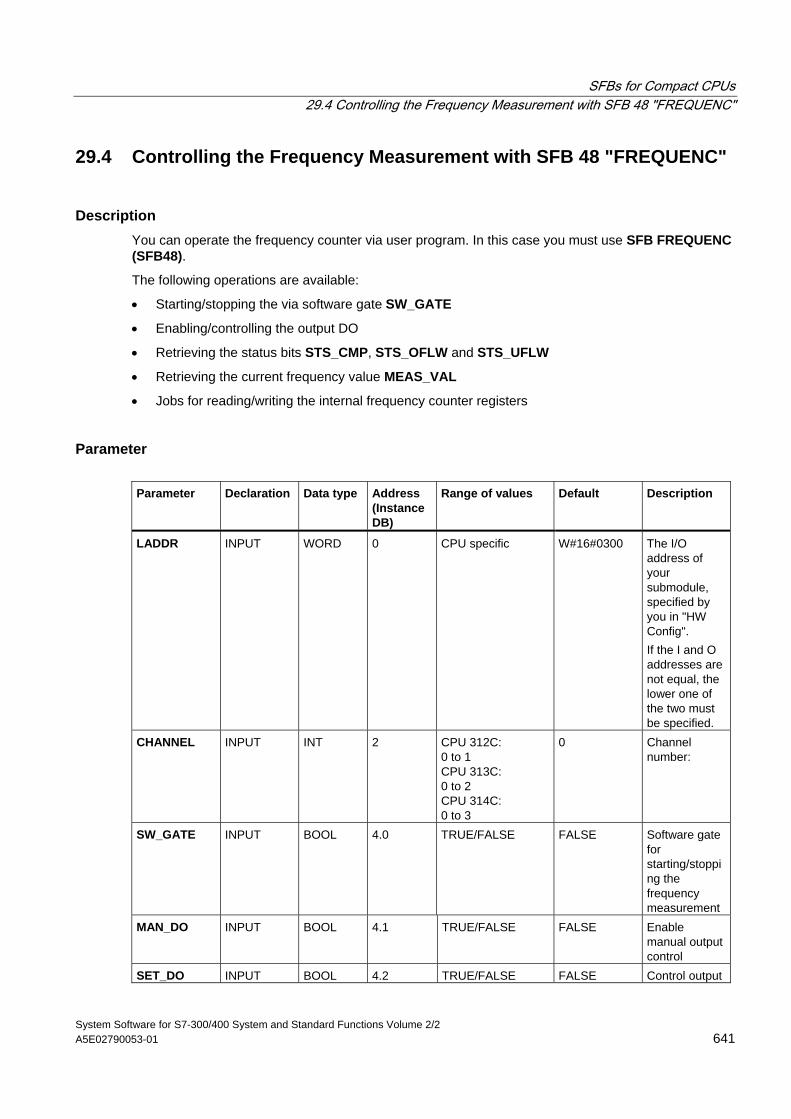
SFBs for Compact CPUs 29.4 Controlling the Frequency Measurement with SFB 48 "FREQUENC"
System Software for S7-300/400 System and Standard Functions Volume 2/2 A5E02790053-01 641
29.4 Controlling the Frequency Measurement with SFB 48 "FREQUENC"
Description You can operate the frequency counter via user program. In this case you must use SFB FREQUENC (SFB48).
The following operations are available:
• Starting/stopping the via software gate SW_GATE
• Enabling/controlling the output DO
• Retrieving the status bits STS_CMP, STS_OFLW and STS_UFLW
• Retrieving the current frequency value MEAS_VAL
• Jobs for reading/writing the internal frequency counter registers
Parameter Parameter Declaration Data type Address
(Instance DB)
Range of values Default Description
LADDR INPUT WORD 0 CPU specific W#16#0300 The I/O address of your submodule, specified by you in "HW Config". If the I and O addresses are not equal, the lower one of the two must be specified.
CHANNEL INPUT INT 2
CPU 312C: 0 to 1 CPU 313C: 0 to 2 CPU 314C: 0 to 3
0 Channel number:
SW_GATE INPUT BOOL 4.0 TRUE/FALSE FALSE Software gate for starting/stopping the frequency measurement
MAN_DO INPUT BOOL 4.1 TRUE/FALSE FALSE Enable manual output control
SET_DO INPUT BOOL 4.2 TRUE/FALSE FALSE Control output
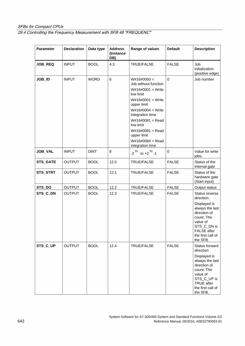
SFBs for Compact CPUs 29.4 Controlling the Frequency Measurement with SFB 48 "FREQUENC"
System Software for S7-300/400 System and Standard Functions Volume 2/2 642 Reference Manual, 05/2010, A5E02790053-01
Parameter Declaration Data type Address (Instance DB)
Range of values Default Description
JOB_REQ INPUT BOOL 4.3 TRUE/FALSE FALSE Job initialization (positive edge)
JOB_ID INPUT WORD 6 W#16#0000 = Job without function W#16#0001 = Write low limit W#16#0001 = Write upper limit W#16#0004 = Write integration time W#16#0081 = Read low limit W#16#0081 = Read upper limit W#16#0084 = Read integration time
0 Job number
JOB_VAL INPUT DINT 8 -231
to +231
-1 0 Value for write jobs.
STS_GATE OUTPUT BOOL 12.0 TRUE/FALSE FALSE Status of the internal gate
STS_STRT OUTPUT BOOL 12.1 TRUE/FALSE FALSE Status of the hardware gate (Start input)
STS_DO OUTPUT BOOL 12.2 TRUE/FALSE FALSE Output status STS_C_DN OUTPUT BOOL 12.3 TRUE/FALSE FALSE Status reverse
direction. Displayed is always the last direction of count. The value of STS_C_DN is FALSE after the first call of the SFB.
STS_C_UP OUTPUT BOOL 12.4 TRUE/FALSE FALSE Status forward direction Displayed is always the last direction of count. The value of STS_C_UP is TRUE after the first call of the SFB.
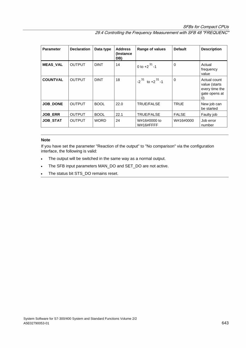
SFBs for Compact CPUs 29.4 Controlling the Frequency Measurement with SFB 48 "FREQUENC"
System Software for S7-300/400 System and Standard Functions Volume 2/2 A5E02790053-01 643
Parameter Declaration Data type Address (Instance DB)
Range of values Default Description
MEAS_VAL OUTPUT DINT 14 0 to +231
-1 0 Actual frequency value
COUNTVAL OUTPUT DINT 18 -231
to +231
-1 0 Actual count value (starts every time the gate opens at 0)
JOB_DONE OUTPUT BOOL 22.0 TRUE/FALSE TRUE New job can be started
JOB_ERR OUTPUT BOOL 22.1 TRUE/FALSE FALSE Faulty job JOB_STAT OUTPUT WORD 24 W#16#0000 to
W#16#FFFF W#16#0000 Job error
number
Note If you have set the parameter "Reaction of the output" to "No comparison" via the configuration interface, the following is valid:
• The output will be switched in the same way as a normal output.
• The SFB input parameters MAN_DO and SET_DO are not active.
• The status bit STS_DO remains reset.
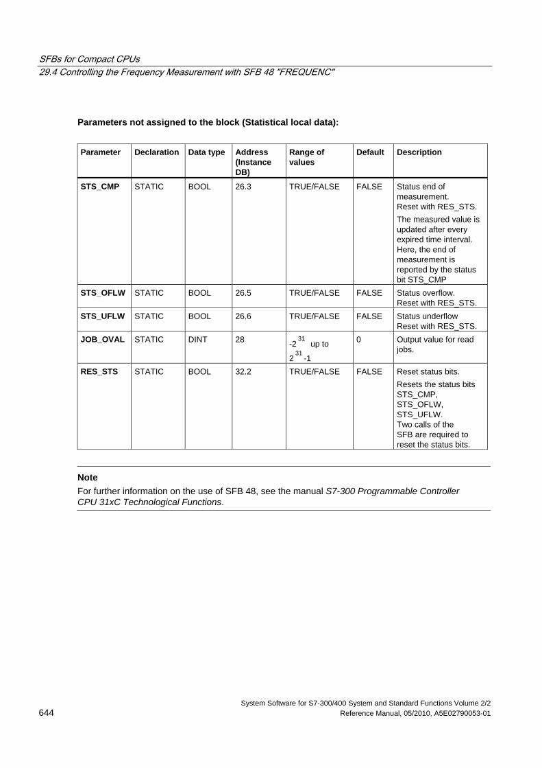
SFBs for Compact CPUs 29.4 Controlling the Frequency Measurement with SFB 48 "FREQUENC"
System Software for S7-300/400 System and Standard Functions Volume 2/2 644 Reference Manual, 05/2010, A5E02790053-01
Parameters not assigned to the block (Statistical local data):
Parameter Declaration Data type Address
(Instance DB)
Range of values
Default Description
STS_CMP STATIC BOOL 26.3 TRUE/FALSE FALSE Status end of measurement. Reset with RES_STS. The measured value is updated after every expired time interval. Here, the end of measurement is reported by the status bit STS_CMP
STS_OFLW STATIC BOOL 26.5 TRUE/FALSE FALSE Status overflow. Reset with RES_STS.
STS_UFLW STATIC BOOL 26.6 TRUE/FALSE FALSE Status underflow Reset with RES_STS.
JOB_OVAL STATIC DINT 28 -231
up to
231
-1
0 Output value for read jobs.
RES_STS STATIC BOOL 32.2 TRUE/FALSE FALSE Reset status bits. Resets the status bits STS_CMP, STS_OFLW, STS_UFLW. Two calls of the SFB are required to reset the status bits.
Note
For further information on the use of SFB 48, see the manual S7-300 Programmable Controller CPU 31xC Technological Functions.
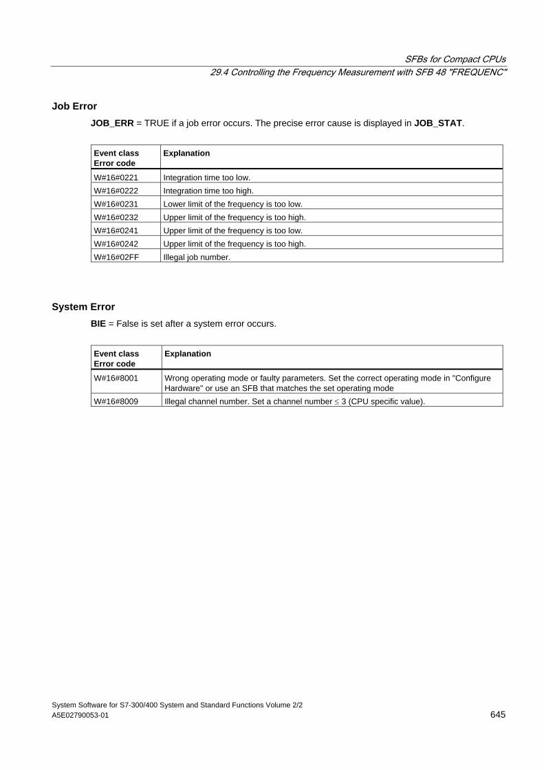
SFBs for Compact CPUs 29.4 Controlling the Frequency Measurement with SFB 48 "FREQUENC"
System Software for S7-300/400 System and Standard Functions Volume 2/2 A5E02790053-01 645
Job Error JOB_ERR = TRUE if a job error occurs. The precise error cause is displayed in JOB_STAT.
Event class Error code
Explanation
W#16#0221 Integration time too low. W#16#0222 Integration time too high. W#16#0231 Lower limit of the frequency is too low. W#16#0232 Upper limit of the frequency is too high. W#16#0241 Upper limit of the frequency is too low. W#16#0242 Upper limit of the frequency is too high. W#16#02FF Illegal job number.
System Error BIE = False is set after a system error occurs.
Event class Error code
Explanation
W#16#8001 Wrong operating mode or faulty parameters. Set the correct operating mode in "Configure Hardware" or use an SFB that matches the set operating mode
W#16#8009 Illegal channel number. Set a channel number ≤ 3 (CPU specific value).
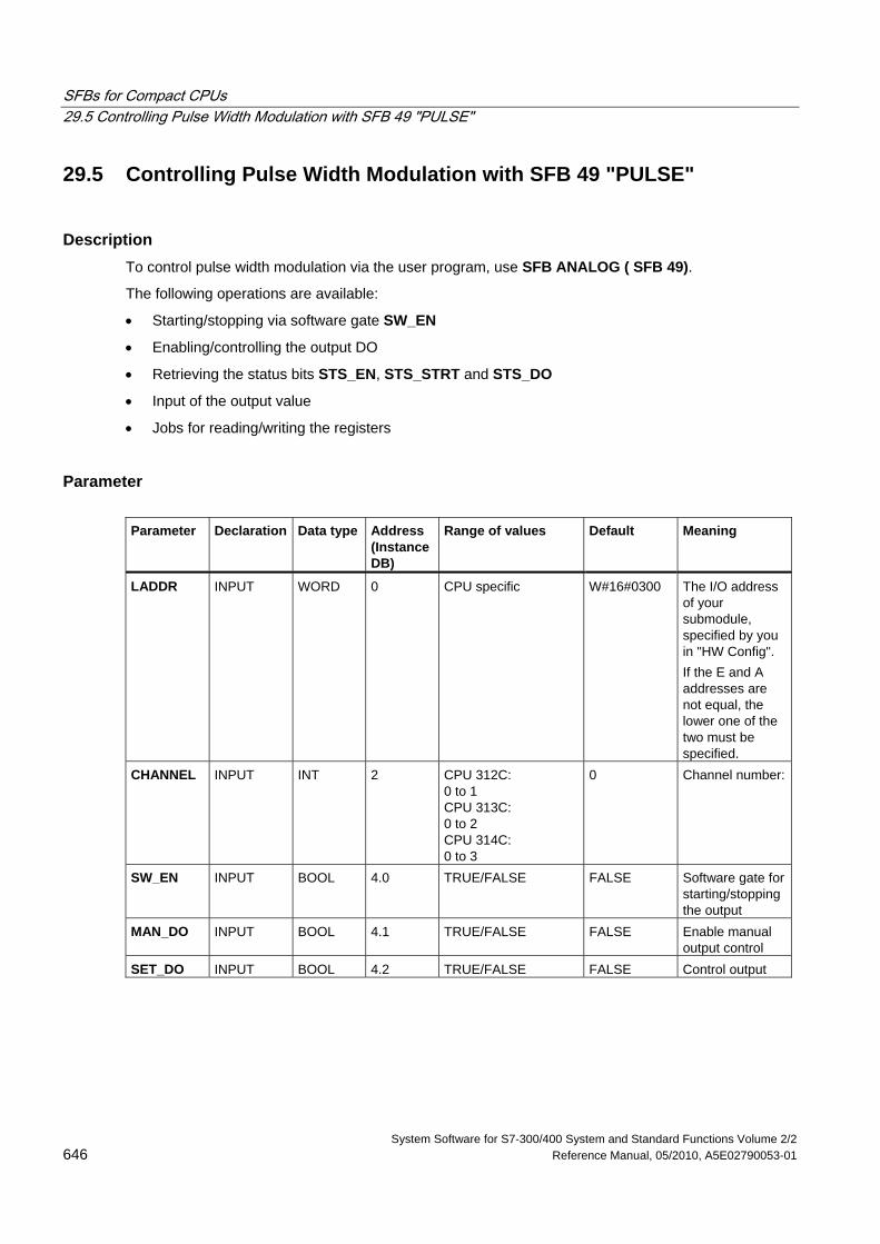
SFBs for Compact CPUs 29.5 Controlling Pulse Width Modulation with SFB 49 "PULSE"
System Software for S7-300/400 System and Standard Functions Volume 2/2 646 Reference Manual, 05/2010, A5E02790053-01
29.5 Controlling Pulse Width Modulation with SFB 49 "PULSE"
Description To control pulse width modulation via the user program, use SFB ANALOG ( SFB 49).
The following operations are available:
• Starting/stopping via software gate SW_EN
• Enabling/controlling the output DO
• Retrieving the status bits STS_EN, STS_STRT and STS_DO
• Input of the output value
• Jobs for reading/writing the registers
Parameter Parameter Declaration Data type Address
(Instance DB)
Range of values Default Meaning
LADDR INPUT WORD 0 CPU specific W#16#0300 The I/O address of your submodule, specified by you in "HW Config". If the E and A addresses are not equal, the lower one of the two must be specified.
CHANNEL INPUT INT 2
CPU 312C: 0 to 1 CPU 313C: 0 to 2 CPU 314C: 0 to 3
0 Channel number:
SW_EN INPUT BOOL 4.0 TRUE/FALSE FALSE Software gate for starting/stopping the output
MAN_DO INPUT BOOL 4.1 TRUE/FALSE FALSE Enable manual output control
SET_DO INPUT BOOL 4.2 TRUE/FALSE FALSE Control output
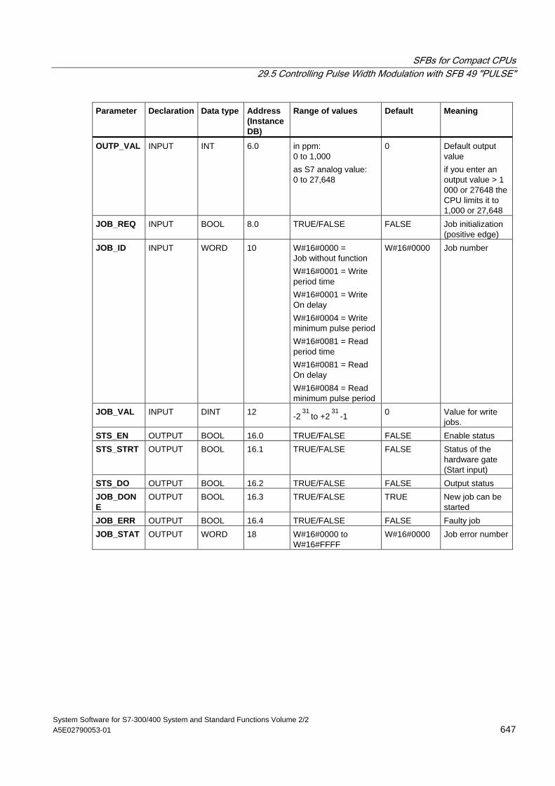
SFBs for Compact CPUs 29.5 Controlling Pulse Width Modulation with SFB 49 "PULSE"
System Software for S7-300/400 System and Standard Functions Volume 2/2 A5E02790053-01 647
Parameter Declaration Data type Address (Instance DB)
Range of values Default Meaning
OUTP_VAL INPUT INT 6.0 in ppm: 0 to 1,000 as S7 analog value: 0 to 27,648
0 Default output value if you enter an output value > 1 000 or 27648 the CPU limits it to 1,000 or 27,648
JOB_REQ INPUT BOOL 8.0 TRUE/FALSE FALSE Job initialization (positive edge)
JOB_ID INPUT WORD 10 W#16#0000 = Job without function W#16#0001 = Write period time W#16#0001 = Write On delay W#16#0004 = Write minimum pulse period W#16#0081 = Read period time W#16#0081 = Read On delay W#16#0084 = Read minimum pulse period
W#16#0000 Job number
JOB_VAL INPUT DINT 12 -231
to +231
-1 0 Value for write jobs.
STS_EN OUTPUT BOOL 16.0 TRUE/FALSE FALSE Enable status STS_STRT OUTPUT BOOL 16.1 TRUE/FALSE FALSE Status of the
hardware gate (Start input)
STS_DO OUTPUT BOOL 16.2 TRUE/FALSE FALSE Output status JOB_DONE
OUTPUT BOOL 16.3 TRUE/FALSE TRUE New job can be started
JOB_ERR OUTPUT BOOL 16.4 TRUE/FALSE FALSE Faulty job JOB_STAT OUTPUT WORD 18 W#16#0000 to
W#16#FFFF W#16#0000 Job error number
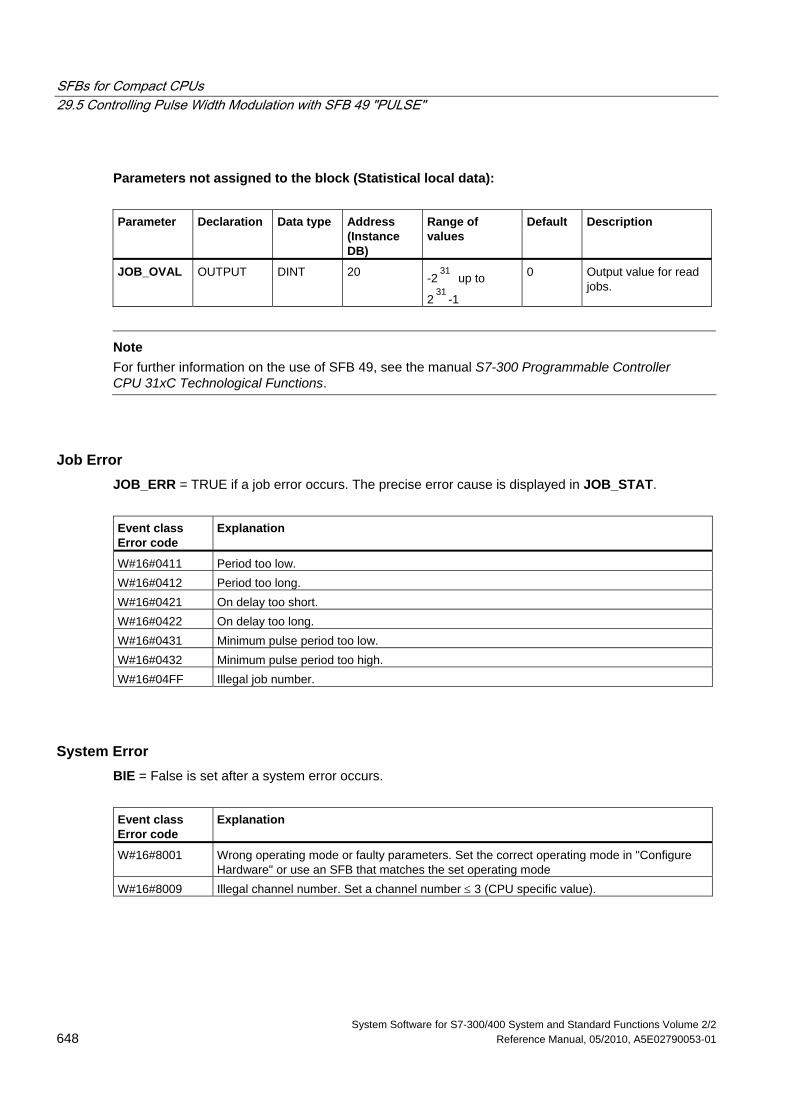
SFBs for Compact CPUs 29.5 Controlling Pulse Width Modulation with SFB 49 "PULSE"
System Software for S7-300/400 System and Standard Functions Volume 2/2 648 Reference Manual, 05/2010, A5E02790053-01
Parameters not assigned to the block (Statistical local data):
Parameter Declaration Data type Address
(Instance DB)
Range of values
Default Description
JOB_OVAL OUTPUT DINT 20 -231
up to
231
-1
0 Output value for read jobs.
Note
For further information on the use of SFB 49, see the manual S7-300 Programmable Controller CPU 31xC Technological Functions.
Job Error JOB_ERR = TRUE if a job error occurs. The precise error cause is displayed in JOB_STAT.
Event class Error code
Explanation
W#16#0411 Period too low. W#16#0412 Period too long. W#16#0421 On delay too short. W#16#0422 On delay too long. W#16#0431 Minimum pulse period too low. W#16#0432 Minimum pulse period too high. W#16#04FF Illegal job number.
System Error BIE = False is set after a system error occurs.
Event class Error code
Explanation
W#16#8001 Wrong operating mode or faulty parameters. Set the correct operating mode in "Configure Hardware" or use an SFB that matches the set operating mode
W#16#8009 Illegal channel number. Set a channel number ≤ 3 (CPU specific value).
SFBs for Compact CPUs 29.6 Sending Data (ASCII, 3964(R)) with SFB 60 "SEND_PTP"
System Software for S7-300/400 System and Standard Functions Volume 2/2 A5E02790053-01 649
29.6 Sending Data (ASCII, 3964(R)) with SFB 60 "SEND_PTP"
Description You can transmit a data block from a DB via SFB SEND_PTP (SFB 60).
The send operation is executed after the block is called and a positive edge on control input REQ.
The range of data to be transmitted is determined in SD_1 (DB number and start address). The length of the data block is determined in LEN.
To enable the SFB to process the job, you must call it with R(Reset)=FALSE. At the positive edge on control input R the current transmission is aborted and the SFB is reset to basic state. An aborted job is terminated with an error message (STATUS output).
For your submodule, you declare the I/O address, which you specified in "HW Config", in LADDR.
DONE is set TRUE if the job was terminated without error, or ERROR is set TRUE if the job was terminated with an error.
If the job was processed with DONE=TRUE this means that:
• When using the ASCII driver: The data where transmitted to the communication partner. It is not ensured that all data has been received by the communication partner.
• When using the procedure 3964(R): The data have been transmitted to the communication partner and they where acknowledged positively by the partner. It is not ensured that the data were passed on the partner CPU.
In STATUS the CPU indicates an error or, as a result of a warning, the respective event ID.
DONE or ERROR/STATUS are also output when the SFB is RESET (R=TRUE).
The binary result BIE is reset if an error has occurred. The status of the binary result is TRUE if the block was terminated without error.
Note
A parameter check is not included in the SFB. The CPU might go into STOP mode if the parameterization is faulty.
Instance DB The SFB SEND_PTP operates in combination with an instance DB. The DB number is passed on with the call. Accessing data in the instance DB is not permitted.
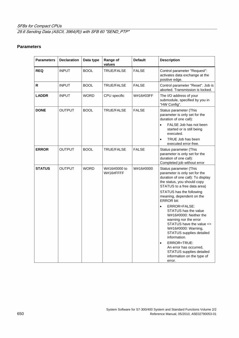
SFBs for Compact CPUs 29.6 Sending Data (ASCII, 3964(R)) with SFB 60 "SEND_PTP"
System Software for S7-300/400 System and Standard Functions Volume 2/2 650 Reference Manual, 05/2010, A5E02790053-01
Parameters Parameters Declaration Data type Range of
values Default Description
REQ INPUT BOOL TRUE/FALSE FALSE Control parameter "Request": activates data exchange at the positive edge.
R INPUT BOOL TRUE/FALSE FALSE Control parameter "Reset". Job is aborted. Transmission is locked.
LADDR INPUT WORD CPU specific W#16#03FF The I/O address of your submodule, specified by you in "HW Config".
DONE OUTPUT BOOL TRUE/FALSE FALSE Status parameter (This parameter is only set for the duration of one call): • FALSE Job has not been
started or is still being executed.
• TRUE Job has been executed error-free.
ERROR OUTPUT BOOL TRUE/FALSE FALSE Status parameter (This parameter is only set for the duration of one call): Completed job without error
STATUS OUTPUT WORD W#16#0000 to W#16#FFFF
W#16#0000 Status parameter (This parameter is only set for the duration of one call): To display the status, you should copy STATUS to a free data area) STATUS has the following meaning, dependent on the ERROR bit: • ERROR=FALSE:
STATUS has the value W#16#0000: Neither the warning nor the error STATUS have the value <> W#16#0000: Warning, STATUS supplies detailed information.
• ERROR=TRUE: An error has occurred, STATUS supplies detailed information on the type of error.
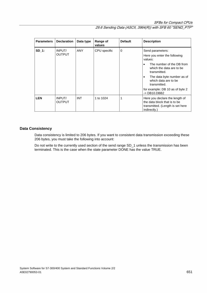
SFBs for Compact CPUs 29.6 Sending Data (ASCII, 3964(R)) with SFB 60 "SEND_PTP"
System Software for S7-300/400 System and Standard Functions Volume 2/2 A5E02790053-01 651
Parameters Declaration Data type Range of values
Default Description
SD_1: INPUT/ OUTPUT
ANY CPU specific
0 Send parameters: Here you enter the following values: • The number of the DB from
which the data are to be transmitted.
• The data byte number as of which data are to be transmitted.
for example: DB 10 as of byte 2 -> DB10.DBB2
LEN INPUT/ OUTPUT
INT 1 to 1024 1 Here you declare the length of the data block that is to be transmitted. (Length is set here indirectly.)
Data Consistency Data consistency is limited to 206 bytes. If you want to consistent data transmission exceeding these 206 bytes, you must take the following into account:
Do not write to the currently used section of the send range SD_1 unless the transmission has been terminated. This is the case when the state parameter DONE has the value TRUE.
SFBs for Compact CPUs 29.7 Receiving Data (ASCII, 3964(R)) with SFB 61 "RCV_PTP"
System Software for S7-300/400 System and Standard Functions Volume 2/2 652 Reference Manual, 05/2010, A5E02790053-01
29.7 Receiving Data (ASCII, 3964(R)) with SFB 61 "RCV_PTP"
Description With the SFB RCV_PTP (SFB 61) you receive data and then file them in a data block.
The block is ready to receive data after it is called and when the control input EN_R is TRUE. You can cancel the current transmission by setting the signal status of parameter EN_R to FALSE. A cancelled job is terminated with an error message (STATUS output). The input is switched off as long as the signal status of parameter EN_R is set to FALSE.
The receiving area declared in RD_1 (DB number and start address). The length of the data block is declared in LEN.
To enable the SFB to process the job, you must call it with R(Reset)=FALSE. At the positive edge on control input R the current transmission is aborted and the SFB is reset to basic state. A cancelled job is terminated with an error message (STATUS output).
For your submodule, you declare the I/O address, which you specified by in "HW Config", in LADDR.
NDR is set TRUE if the job was terminated without error, or ERROR is set TRUE if the job was terminated with an error.
In STATUS, the CPU indicates an error or, as a result of a warning, the respective event ID.
NDR or ERROR/STATUS are also output (parameter LEN = 16#00) when the SFB is RESET (R=TRUE).
The binary result BIE is reset if an error has occurred. The status of the binary result is TRUE if the block was terminated without error.
Note
A parameter check is not included in the SFB. The CPU might jump to STOP mode if the configuration is faulty.
Instance DB The SFB RCV_PTP operates in combination with an instance DB. The DB number is passed on with the call. Access to the data in the instance DB is not allowed.
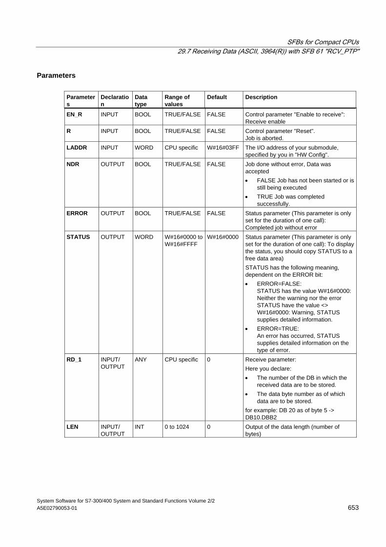
SFBs for Compact CPUs 29.7 Receiving Data (ASCII, 3964(R)) with SFB 61 "RCV_PTP"
System Software for S7-300/400 System and Standard Functions Volume 2/2 A5E02790053-01 653
Parameters Parameters
Declaration
Data type
Range of values
Default Description
EN_R INPUT BOOL TRUE/FALSE FALSE Control parameter "Enable to receive": Receive enable
R INPUT BOOL TRUE/FALSE FALSE Control parameter "Reset". Job is aborted.
LADDR INPUT WORD CPU specific W#16#03FF The I/O address of your submodule, specified by you in "HW Config".
NDR OUTPUT BOOL TRUE/FALSE FALSE Job done without error, Data was accepted • FALSE Job has not been started or is
still being executed • TRUE Job was completed
successfully. ERROR OUTPUT BOOL TRUE/FALSE FALSE Status parameter (This parameter is only
set for the duration of one call): Completed job without error
STATUS OUTPUT WORD W#16#0000 to W#16#FFFF
W#16#0000 Status parameter (This parameter is only set for the duration of one call): To display the status, you should copy STATUS to a free data area) STATUS has the following meaning, dependent on the ERROR bit: • ERROR=FALSE:
STATUS has the value W#16#0000: Neither the warning nor the error STATUS have the value <> W#16#0000: Warning, STATUS supplies detailed information.
• ERROR=TRUE: An error has occurred, STATUS supplies detailed information on the type of error.
RD_1 INPUT/ OUTPUT
ANY CPU specific 0 Receive parameter: Here you declare: • The number of the DB in which the
received data are to be stored. • The data byte number as of which
data are to be stored. for example: DB 20 as of byte 5 -> DB10.DBB2
LEN INPUT/ OUTPUT
INT 0 to 1024 0 Output of the data length (number of bytes)
SFBs for Compact CPUs 29.7 Receiving Data (ASCII, 3964(R)) with SFB 61 "RCV_PTP"
System Software for S7-300/400 System and Standard Functions Volume 2/2 654 Reference Manual, 05/2010, A5E02790053-01
Data Consistency Data consistency is limited to 206 bytes. If you want consistent data transmission to exceed these 206 bytes, you must take the following points into account:
Do not access the receive DB until the data have been completely received (NDR = TRUE). Then, lock the receiving DB (EN_R = FALSE) until you have processed the data.
SFBs for Compact CPUs 29.8 Deleting the Receive Buffer (ASCII, 3964(R)) with SFB 62 "RES_RCVB"
System Software for S7-300/400 System and Standard Functions Volume 2/2 A5E02790053-01 655
29.8 Deleting the Receive Buffer (ASCII, 3964(R)) with SFB 62 "RES_RCVB"
Description You can clear the entire input buffer of the module, using the SFB RES_RECV (SFB 62). All stored telegrams are discarded. An incoming message frame is stored when the SFB RES_RCVB is being called.
The job is activated after the block is called and at the positive edge on control input REQ. The job can run across multiple calls (program cycles).
To enable the SFB to process the job, you must call it with R(Reset)=FALSE. At the positive edge on control input R the delete process is cancelled and the SFB is reset to basic state. A cancelled job is terminated with an error message (STATUS output).
For your submodule, you declare the I/O address, which was specified by you in "HW Config", in LADDR.
DONE is TRUE is the job was terminated without error, or ERROR is TRUE if the job was terminated with an error.
In STATUS, the CPU indicates an error or, as a result of a warning, the respective event ID.
DONE or ERROR/STATUS are also output when the SFB is RESET (R=TRUE).
The binary result BIE is reset if an error has occurred. The status of the binary result is TRUE if the block was terminated without error.
Note
A parameter check is not included in the SFB. The CPU might jump to STOP mode if the parameterization is faulty.
Instance DB The SFB RES_RCVB operates in combination with an instance DB. The DB number is passed on with the call. Access to the data in the instance DB is not allowed.
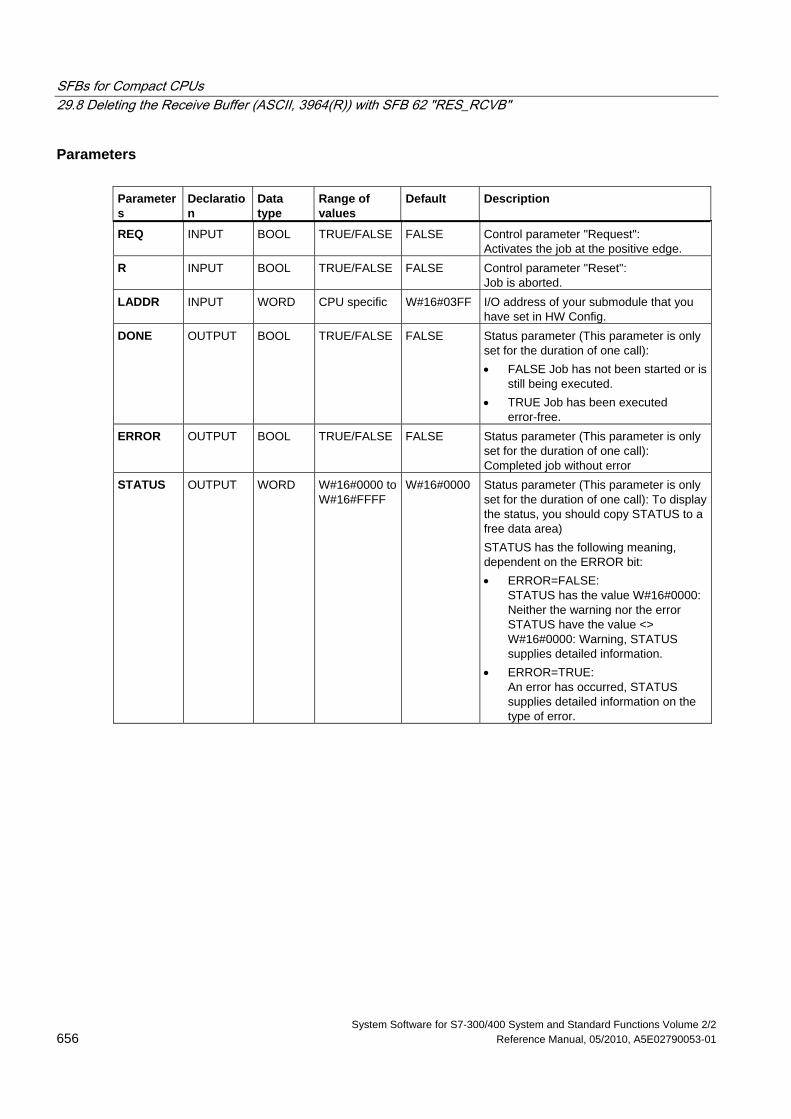
SFBs for Compact CPUs 29.8 Deleting the Receive Buffer (ASCII, 3964(R)) with SFB 62 "RES_RCVB"
System Software for S7-300/400 System and Standard Functions Volume 2/2 656 Reference Manual, 05/2010, A5E02790053-01
Parameters Parameters
Declaration
Data type
Range of values
Default Description
REQ INPUT BOOL TRUE/FALSE FALSE Control parameter "Request": Activates the job at the positive edge.
R INPUT BOOL TRUE/FALSE FALSE Control parameter "Reset": Job is aborted.
LADDR INPUT WORD CPU specific W#16#03FF I/O address of your submodule that you have set in HW Config.
DONE OUTPUT BOOL TRUE/FALSE FALSE Status parameter (This parameter is only set for the duration of one call): • FALSE Job has not been started or is
still being executed. • TRUE Job has been executed
error-free. ERROR OUTPUT BOOL TRUE/FALSE FALSE Status parameter (This parameter is only
set for the duration of one call): Completed job without error
STATUS OUTPUT WORD W#16#0000 to W#16#FFFF
W#16#0000 Status parameter (This parameter is only set for the duration of one call): To display the status, you should copy STATUS to a free data area) STATUS has the following meaning, dependent on the ERROR bit: • ERROR=FALSE:
STATUS has the value W#16#0000: Neither the warning nor the error STATUS have the value <> W#16#0000: Warning, STATUS supplies detailed information.
• ERROR=TRUE: An error has occurred, STATUS supplies detailed information on the type of error.
SFBs for Compact CPUs 29.9 Sending Data (512(R)) with SFB 63 "SEND_RK"
System Software for S7-300/400 System and Standard Functions Volume 2/2 A5E02790053-01 657
29.9 Sending Data (512(R)) with SFB 63 "SEND_RK"
Description You can send a data from a data block via SFB SEND_PTP (SFB 63).
The send operation is executed after the block is called and a positive edge on control input REQ.
The range of data to be transmitted is determined in SD_1 (DB number and start address). The length of the data block is determined in LEN.
In the SFB you also declare the receive range of the partner station. The CPU enters this information in the message frame header (refer also to appendix F) and transfers it to the partner.
The target is specified by the CPU number R_CPU (only relevant for multiprocessor communication), the data type in R_TYPE (data blocks (DB) and expanded data blocks (DX)), the data block number in R_DBNO and the offset in R_OFFSET to where the first byte is to be written.
In R_CF_BYT and R_CF_BIT, declare the connection memory byte and bit on the partner CPU.
In parameter SYNC_DB, declare the DB in which the data that you used in all SFBs for the initialization during startup and synchronization is to be stored. The DB numbers must be identical for all SFBs in your user program.
To enable the SFB to process the job, you must call it with R(Reset)=FALSE. At the positive edge on control input R the current send operation is cancelled and the SFB is reset to basic state. A cancelled job is terminated with an error message (STATUS output).
For your submodule, you declare the I/O address, which you specified in "HW Config", in LADDR.
DONE is set TRUE if the job was terminated without error, or ERROR is set TRUE if the job was terminated with an error.
Once the job was processed with DONE = TRUE, the data are sent to the communication partner that confirms them positively and passes them on to the partner CPU.
In STATUS, the CPU indicates an error or, as a result of a warning, the respective event ID.
DONE or ERROR/STATUS are also output when the SFB is RESET (R=TRUE).
The binary result BIE is reset if an error has occurred. The status of the binary result is TRUE if the block was terminated without error.
Note
A parameter check is not included in the SFB. If the CPU is assigned the wrong parameters it might jump to STOP mode.
Instance DB The SFB SEND_RK operates in combination with an instance DB. The DB number is passed on with the call. Access to the data in the instance DB is not allowed.
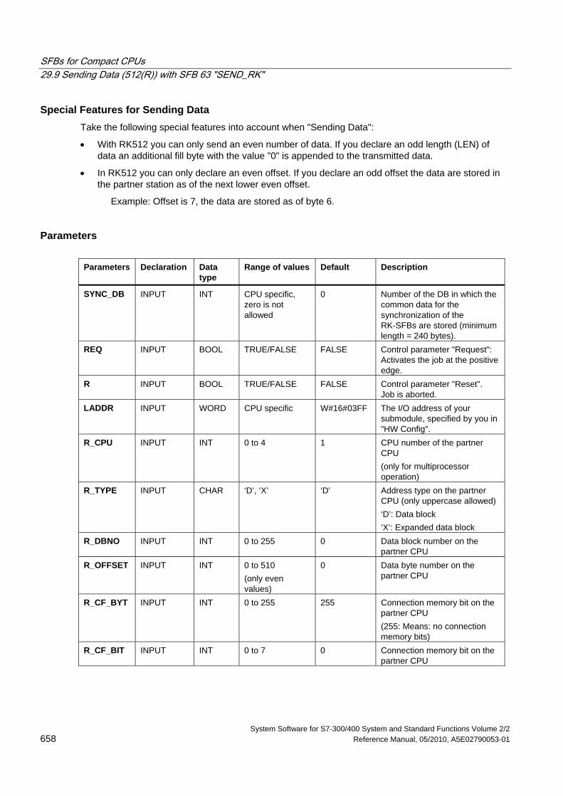
SFBs for Compact CPUs 29.9 Sending Data (512(R)) with SFB 63 "SEND_RK"
System Software for S7-300/400 System and Standard Functions Volume 2/2 658 Reference Manual, 05/2010, A5E02790053-01
Special Features for Sending Data Take the following special features into account when "Sending Data":
• With RK512 you can only send an even number of data. If you declare an odd length (LEN) of data an additional fill byte with the value "0" is appended to the transmitted data.
• In RK512 you can only declare an even offset. If you declare an odd offset the data are stored in the partner station as of the next lower even offset.
Example: Offset is 7, the data are stored as of byte 6.
Parameters Parameters Declaration Data
type Range of values Default Description
SYNC_DB INPUT INT CPU specific, zero is not allowed
0 Number of the DB in which the common data for the synchronization of the RK-SFBs are stored (minimum length = 240 bytes).
REQ INPUT BOOL TRUE/FALSE FALSE Control parameter "Request": Activates the job at the positive edge.
R INPUT BOOL TRUE/FALSE FALSE Control parameter "Reset". Job is aborted.
LADDR INPUT WORD CPU specific W#16#03FF The I/O address of your submodule, specified by you in "HW Config".
R_CPU INPUT INT 0 to 4 1 CPU number of the partner CPU (only for multiprocessor operation)
R_TYPE INPUT CHAR ‘D’, ‘X’ ‘D’ Address type on the partner CPU (only uppercase allowed) ‘D’: Data block ‘X’: Expanded data block
R_DBNO INPUT INT 0 to 255 0 Data block number on the partner CPU
R_OFFSET INPUT INT 0 to 510 (only even values)
0 Data byte number on the partner CPU
R_CF_BYT INPUT INT 0 to 255 255 Connection memory bit on the partner CPU (255: Means: no connection memory bits)
R_CF_BIT INPUT INT 0 to 7 0 Connection memory bit on the partner CPU
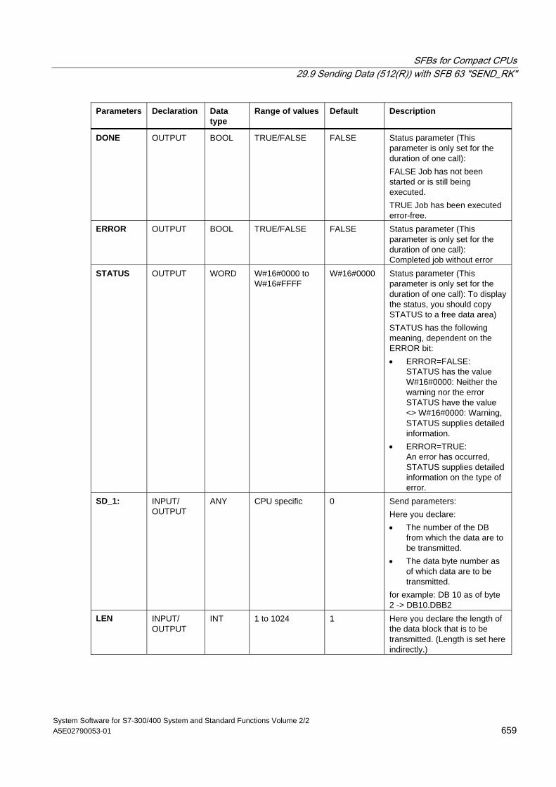
SFBs for Compact CPUs 29.9 Sending Data (512(R)) with SFB 63 "SEND_RK"
System Software for S7-300/400 System and Standard Functions Volume 2/2 A5E02790053-01 659
Parameters Declaration Data type
Range of values Default Description
DONE OUTPUT BOOL TRUE/FALSE FALSE Status parameter (This parameter is only set for the duration of one call): FALSE Job has not been started or is still being executed. TRUE Job has been executed error-free.
ERROR OUTPUT BOOL TRUE/FALSE FALSE Status parameter (This parameter is only set for the duration of one call): Completed job without error
STATUS OUTPUT WORD W#16#0000 to W#16#FFFF
W#16#0000 Status parameter (This parameter is only set for the duration of one call): To display the status, you should copy STATUS to a free data area) STATUS has the following meaning, dependent on the ERROR bit: • ERROR=FALSE:
STATUS has the value W#16#0000: Neither the warning nor the error STATUS have the value <> W#16#0000: Warning, STATUS supplies detailed information.
• ERROR=TRUE: An error has occurred, STATUS supplies detailed information on the type of error.
SD_1: INPUT/ OUTPUT
ANY CPU specific 0 Send parameters: Here you declare: • The number of the DB
from which the data are to be transmitted.
• The data byte number as of which data are to be transmitted.
for example: DB 10 as of byte 2 -> DB10.DBB2
LEN INPUT/ OUTPUT
INT 1 to 1024 1 Here you declare the length of the data block that is to be transmitted. (Length is set here indirectly.)
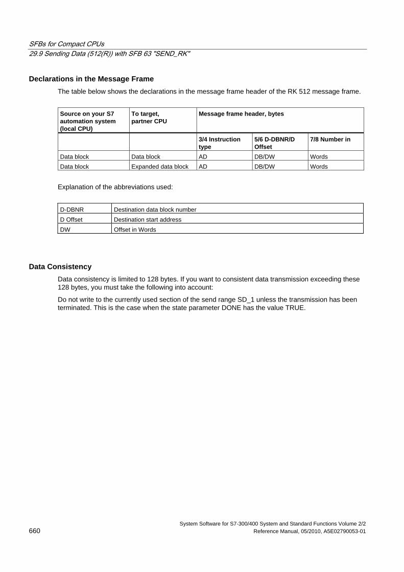
SFBs for Compact CPUs 29.9 Sending Data (512(R)) with SFB 63 "SEND_RK"
System Software for S7-300/400 System and Standard Functions Volume 2/2 660 Reference Manual, 05/2010, A5E02790053-01
Declarations in the Message Frame The table below shows the declarations in the message frame header of the RK 512 message frame.
Source on your S7 automation system (local CPU)
To target, partner CPU
Message frame header, bytes
3/4 Instruction type
5/6 D-DBNR/D Offset
7/8 Number in
Data block Data block AD DB/DW Words Data block Expanded data block AD DB/DW Words
Explanation of the abbreviations used:
D-DBNR Destination data block number D Offset Destination start address DW Offset in Words
Data Consistency Data consistency is limited to 128 bytes. If you want to consistent data transmission exceeding these 128 bytes, you must take the following into account:
Do not write to the currently used section of the send range SD_1 unless the transmission has been terminated. This is the case when the state parameter DONE has the value TRUE.
SFBs for Compact CPUs 29.10 Fetching Data (RK 512) with SFB 64 "FETCH RK"
System Software for S7-300/400 System and Standard Functions Volume 2/2 A5E02790053-01 661
29.10 Fetching Data (RK 512) with SFB 64 "FETCH RK"
Description SFB FETCH_RK (SFB 64) is used to fetch a data block from a partner and store them in a data block.
The send operation is executed after the block is called and a positive edge on control input REQ.
The area in which the fetched data is stored is declared in RD_1 (DB number and start address). The length of the data block is declared in LEN.
In the SFB you also specify the partner area from which the data are fetched. The CPU enters this information in the RK512 message frame header and transfers it to the partner.
The partner area is determined by the CPU number in R_CPU (only relevant for multiprocessor communication), the data type in R_TYPE (data blocks, expanded data blocks, memory bits, inputs, outputs, counters and times), the data block number in R_DBNO (only relevant for data blocks and expanded data blocks) and the offset in R_OFFSET from where the first byte is to be fetched.
In R_CF_BYT and R_CF_BIT you declare the connection memory byte and the connection memory bit on the partner CPU.
In parameter SYNC_DB you declare the DB in which the data that you used in all SFBs for the initialization during startup and synchronization is to be stored. The DB numbers must be identical for all SFBs in your user program.
To enable the SFB to process the job, you must call it with R(Reset)=FALSE. At the positive edge on control input R the current transmission is cancelled and the SFB is reset to basic state. An cancelled job is closed with an error message (STATUS output).
For your submodule, you declare the I/O address, which you specified in "HW Config", in LADDR.
DONE is set TRUE if the job was terminated without error, or ERROR is set TRUE if the job was terminated with an error.
In STATUS, the CPU indicates an error or, as a result of a warning, the respective event ID.
DONE or ERROR/STATUS are also output when the SFB is RESET (R=TRUE).
The binary result BIE is reset if an error has occurred. The status of the binary result is TRUE if the block was terminated without error.
SFBs for Compact CPUs 29.10 Fetching Data (RK 512) with SFB 64 "FETCH RK"
System Software for S7-300/400 System and Standard Functions Volume 2/2 662 Reference Manual, 05/2010, A5E02790053-01
Note
A parameter check is not included in the SFB. The CPU might go to STOP mode if the configuration is faulty.
Note
When data are fetched from your CPU, you must program the SFB "SERVE_RK" for your CPU.
Instance DB The SFB FETCH_RK operates in combination with an instance DB. The DB number is passed on with the call. Access to the data in the instance DB is not allowed.
Special Features for (Expanded) Data Blocks Note the following special features when "Fetching Data" from a data block or an expanded data block:
• With RK512 you can only send an even number of data. An additional byte is transmitted if you enter an odd length (LEN). In the target DB, however, always the correct number of data is entered.
• In RK512 you can only declare an even offset. If you declare an odd offset the data are stored in the partner station as of the next smaller even offset.
Example: Offset is 7, the data are stored as of byte 6.
Special Features for Timers and Counters When you fetch times or counters from your communication partner, you must take into account that you need to fetch two bytes for every time or counter. For example, if you want to fetch 10 counters you must declare a length of 20.
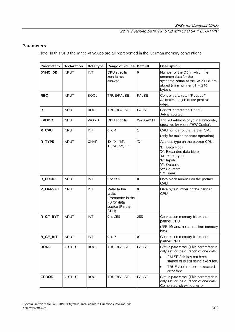
SFBs for Compact CPUs 29.10 Fetching Data (RK 512) with SFB 64 "FETCH RK"
System Software for S7-300/400 System and Standard Functions Volume 2/2 A5E02790053-01 663
Parameters Note: In this SFB the range of values are all represented in the German memory conventions.
Parameters Declaration Data type Range of values Default Description
SYNC_DB INPUT INT CPU specific, zero is not allowed
0 Number of the DB in which the common data for the synchronization of the RK-SFBs are stored (minimum length = 240 bytes).
REQ INPUT BOOL TRUE/FALSE FALSE Control parameter "Request": Activates the job at the positive edge.
R INPUT BOOL TRUE/FALSE FALSE Control parameter "Reset". Job is aborted.
LADDR INPUT WORD CPU specific W#16#03FF The I/O address of your submodule, specified by you in "HW Config".
R_CPU INPUT INT 0 to 4 1 CPU number of the partner CPU (only for multiprocessor operation)
R_TYPE INPUT CHAR ’D’, ’X’, ’M’, ’E’, ’A’, ’Z’, ’T’
‘D’ Address type on the partner CPU ‘D’: Data block ’X’: Expanded data block ’M’: Memory bit ’E’: Inputs ’A’: Outputs ’Z’: Counters ’T’: Times
R_DBNO INPUT INT 0 to 255 0 Data block number on the partner CPU
R_OFFSET INPUT INT Refer to the table: ”Parameter in the FB for data source (Partner CPU)”
0 Data byte number on the partner CPU
R_CF_BYT INPUT INT 0 to 255 255 Connection memory bit on the partner CPU (255: Means: no connection memory bits)
R_CF_BIT INPUT INT 0 to 7 0 Connection memory bit on the partner CPU
DONE OUTPUT BOOL TRUE/FALSE FALSE Status parameter (This parameter is only set for the duration of one call): • FALSE Job has not been
started or is still being executed.• TRUE Job has been executed
error-free. ERROR OUTPUT BOOL TRUE/FALSE FALSE Status parameter (This parameter is
only set for the duration of one call):Completed job without error
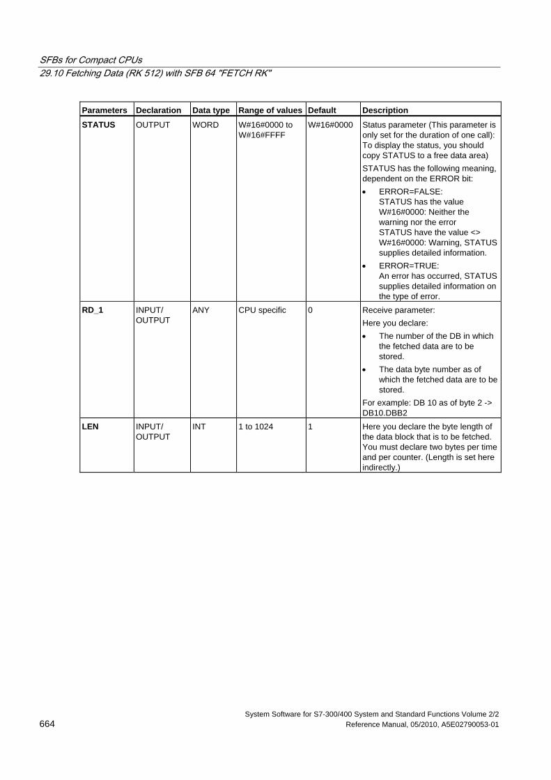
SFBs for Compact CPUs 29.10 Fetching Data (RK 512) with SFB 64 "FETCH RK"
System Software for S7-300/400 System and Standard Functions Volume 2/2 664 Reference Manual, 05/2010, A5E02790053-01
Parameters Declaration Data type Range of values Default Description
STATUS OUTPUT WORD W#16#0000 to W#16#FFFF
W#16#0000 Status parameter (This parameter is only set for the duration of one call): To display the status, you should copy STATUS to a free data area) STATUS has the following meaning, dependent on the ERROR bit: • ERROR=FALSE:
STATUS has the value W#16#0000: Neither the warning nor the error STATUS have the value <> W#16#0000: Warning, STATUS supplies detailed information.
• ERROR=TRUE: An error has occurred, STATUS supplies detailed information on the type of error.
RD_1 INPUT/ OUTPUT
ANY CPU specific 0 Receive parameter: Here you declare: • The number of the DB in which
the fetched data are to be stored.
• The data byte number as of which the fetched data are to be stored.
For example: DB 10 as of byte 2 -> DB10.DBB2
LEN INPUT/ OUTPUT
INT 1 to 1024 1 Here you declare the byte length of the data block that is to be fetched. You must declare two bytes per time and per counter. (Length is set here indirectly.)
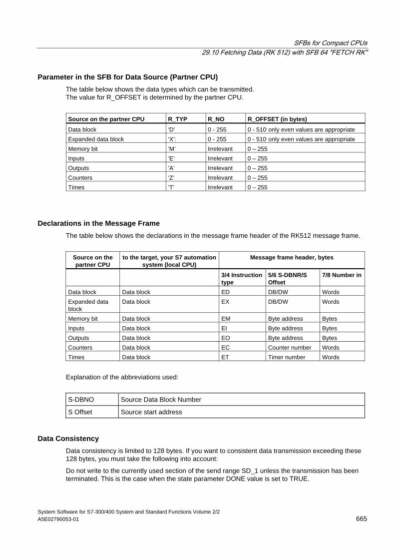
SFBs for Compact CPUs 29.10 Fetching Data (RK 512) with SFB 64 "FETCH RK"
System Software for S7-300/400 System and Standard Functions Volume 2/2 A5E02790053-01 665
Parameter in the SFB for Data Source (Partner CPU) The table below shows the data types which can be transmitted. The value for R_OFFSET is determined by the partner CPU.
Source on the partner CPU R_TYP R_NO R_OFFSET (in bytes)
Data block ‘D’ 0 - 255 0 - 510, only even values are appropriate Expanded data block ‘X’: 0 - 255 0 - 510, only even values are appropriate Memory bit ’M’ Irrelevant 0 – 255 Inputs ’E’ Irrelevant 0 – 255 Outputs ’A’ Irrelevant 0 – 255 Counters ‘Z’ Irrelevant 0 – 255 Times ’T’ Irrelevant 0 – 255
Declarations in the Message Frame The table below shows the declarations in the message frame header of the RK512 message frame.
Source on the partner CPU
to the target, your S7 automation system (local CPU)
Message frame header, bytes
3/4 Instruction type
5/6 S-DBNR/S Offset
7/8 Number in
Data block Data block ED DB/DW Words Expanded data block
Data block EX DB/DW Words
Memory bit Data block EM Byte address Bytes Inputs Data block EI Byte address Bytes Outputs Data block EO Byte address Bytes Counters Data block EC Counter number Words Times Data block ET Timer number Words
Explanation of the abbreviations used:
S-DBNO Source Data Block Number
S Offset Source start address
Data Consistency Data consistency is limited to 128 bytes. If you want to consistent data transmission exceeding these 128 bytes, you must take the following into account:
Do not write to the currently used section of the send range SD_1 unless the transmission has been terminated. This is the case when the state parameter DONE value is set to TRUE.
SFBs for Compact CPUs 29.11 Receiving and Providing Data (RK 512) with SFB 65 "SERVE_RK"
System Software for S7-300/400 System and Standard Functions Volume 2/2 666 Reference Manual, 05/2010, A5E02790053-01
29.11 Receiving and Providing Data (RK 512) with SFB 65 "SERVE_RK"
Description Use the SFB SERVE_RK (SFB 65) to receive and provide data.
• Receiving data: The data are stored in the area that is specified by the partner in the RK512 message frame header. A call of the SFB is required when the communication partner executes a "Send Data" (SEND jobs) job.
• Providing Data: The data are fetched from the area that is specified by the partner in the RK512 message frame header. A call of the SFB is required when the communication partner executes a "Fetch Data" (FETCH jobs) job.
The block is ready to after it is called with the control input EN_R value TRUE. You can cancel the current transmission by setting the signal status of parameter EN_R to FALSE. A cancelled job is terminated with an error message (STATUS output). The input is switched off as long as the signal status of parameter EN_R is set to FALSE.
In parameter SYNC_DB you declare the DB in which the data that is used by you in all SFBs for the initialization during startup and synchronization is to be stored. The DB numbers must be identical for all SFBs in your user program.
To enable the SFB to process the job, you must call it with R(Reset)=FALSE. At the positive edge on control input R the current transmission is cancelled and the SFB is reset to basic state. A cancelled job is terminated with an error message (STATUS output).
For your submodule, you declare the I/O address, which was specified by you in "HW Config", in LADDR.
NDR is set TRUE if the job was terminated without error, or ERROR is set TRUE if the job was terminated with an error.
With NDR=TRUE for an SFB call the CPU indicates in the parameters L_TYPE, L_DBNO and L_OFFSET the area where data were stored or fetched from. Also shown for a call are the parameters L_CF_BYT and L_CF_BIT and the length LEN of the respective job.
In STATUS, the CPU indicates an error or, as a result of a warning, the respective event ID (refer to the appendix).
NDR or ERROR/STATUS are also output (parameter LEN == 16#00) when the SFB is RESET (R=TRUE).
The binary result BIE is reset if an error has occurred. The status of the binary result is TRUE if the block was terminated without error.
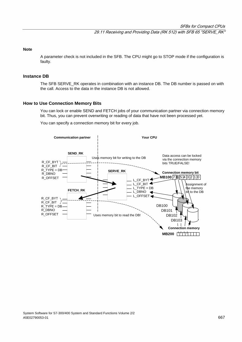
SFBs for Compact CPUs 29.11 Receiving and Providing Data (RK 512) with SFB 65 "SERVE_RK"
System Software for S7-300/400 System and Standard Functions Volume 2/2 A5E02790053-01 667
Note
A parameter check is not included in the SFB. The CPU might go to STOP mode if the configuration is faulty.
Instance DB The SFB SERVE_RK operates in combination with an instance DB. The DB number is passed on with the call. Access to the data in the instance DB is not allowed.
How to Use Connection Memory Bits You can lock or enable SEND and FETCH jobs of your communication partner via connection memory bit. Thus, you can prevent overwriting or reading of data that have not been processed yet.
You can specify a connection memory bit for every job.
Connection memory bit
DB100
MB100 L_CF_BYT L_CF_BIT L_TYPE = DB L_DBNO L_OFFSET
SERVE_RK
Data access can be lockedvia the connection memorybits TRUE/FALSE!
SEND_RK
FETCH_RK
R_CF_BYT R_CF_BIT R_TYPE = DB R_DBNO R_OFFSET
R_CF_BYT R_CF_BITR_TYPE = DB R_DBNO R_OFFSET
Assignment ofthe memorybit to the DB
Uses memory bit for writing to the DB
MB200Connection memory
DB101DB102
DB103Uses memory bit to read the DB!
Communication partner Your CPU
7 6 5 4 3 2 1 0
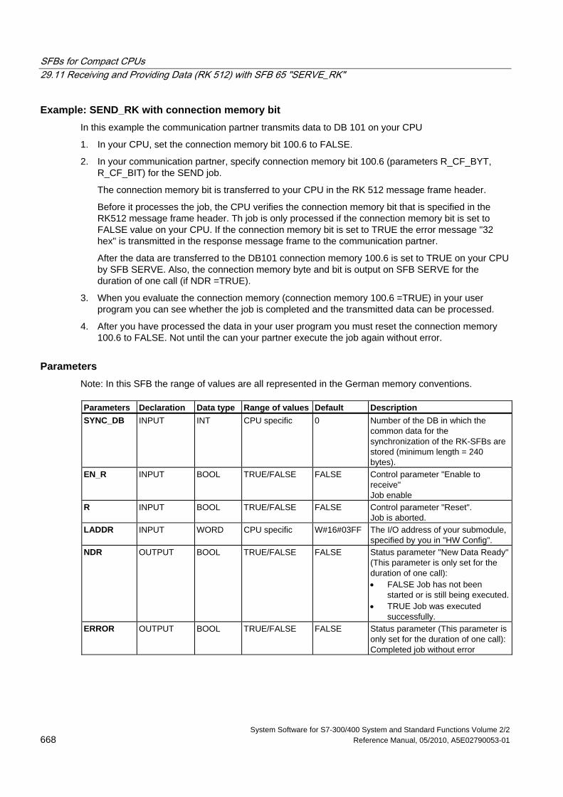
SFBs for Compact CPUs 29.11 Receiving and Providing Data (RK 512) with SFB 65 "SERVE_RK"
System Software for S7-300/400 System and Standard Functions Volume 2/2 668 Reference Manual, 05/2010, A5E02790053-01
Example: SEND_RK with connection memory bit In this example the communication partner transmits data to DB 101 on your CPU
1. In your CPU, set the connection memory bit 100.6 to FALSE.
2. In your communication partner, specify connection memory bit 100.6 (parameters R_CF_BYT, R_CF_BIT) for the SEND job.
The connection memory bit is transferred to your CPU in the RK 512 message frame header.
Before it processes the job, the CPU verifies the connection memory bit that is specified in the RK512 message frame header. Th job is only processed if the connection memory bit is set to FALSE value on your CPU. If the connection memory bit is set to TRUE the error message "32 hex" is transmitted in the response message frame to the communication partner.
After the data are transferred to the DB101 connection memory 100.6 is set to TRUE on your CPU by SFB SERVE. Also, the connection memory byte and bit is output on SFB SERVE for the duration of one call (if NDR =TRUE).
3. When you evaluate the connection memory (connection memory 100.6 =TRUE) in your user program you can see whether the job is completed and the transmitted data can be processed.
4. After you have processed the data in your user program you must reset the connection memory 100.6 to FALSE. Not until the can your partner execute the job again without error.
Parameters Note: In this SFB the range of values are all represented in the German memory conventions. Parameters Declaration Data type Range of values Default Description SYNC_DB INPUT INT CPU specific 0 Number of the DB in which the
common data for the synchronization of the RK-SFBs are stored (minimum length = 240 bytes).
EN_R INPUT BOOL TRUE/FALSE FALSE Control parameter "Enable to receive" Job enable
R INPUT BOOL TRUE/FALSE FALSE Control parameter "Reset". Job is aborted.
LADDR INPUT WORD CPU specific W#16#03FF The I/O address of your submodule, specified by you in "HW Config".
NDR OUTPUT BOOL TRUE/FALSE FALSE Status parameter "New Data Ready" (This parameter is only set for the duration of one call): • FALSE Job has not been
started or is still being executed.• TRUE Job was executed
successfully. ERROR OUTPUT BOOL TRUE/FALSE FALSE Status parameter (This parameter is
only set for the duration of one call):Completed job without error
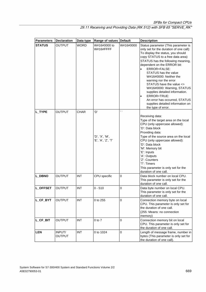
SFBs for Compact CPUs 29.11 Receiving and Providing Data (RK 512) with SFB 65 "SERVE_RK"
System Software for S7-300/400 System and Standard Functions Volume 2/2 A5E02790053-01 669
Parameters Declaration Data type Range of values Default Description STATUS OUTPUT WORD W#16#0000 to
W#16#FFFF W#16#0000 Status parameter (This parameter is
only set for the duration of one call): To display the status, you should copy STATUS to a free data area) STATUS has the following meaning, dependent on the ERROR bit: • ERROR=FALSE:
STATUS has the value W#16#0000: Neither the warning nor the error STATUS have the value <> W#16#0000: Warning, STATUS supplies detailed information.
• ERROR=TRUE: An error has occurred, STATUS supplies detailed information on the type of error.
L_TYPE OUTPUT CHAR ‘D’ ’D’, ’X’, ’M’, ’E’, ’A’, ’Z’, ’T’
’ ’ Receiving data: Type of the target area on the local CPU (only uppercase allowed): ‘D’: Data block Providing data: Type of the source area on the local CPU (only uppercase allowed): ‘D’: Data block ’M’: Memory bit ’E’: Inputs ’A’: Outputs ’Z’: Counters ’T’: Timers This parameter is only set for the duration of one call.
L_DBNO OUTPUT INT CPU specific 0 Data block number on local CPU. This parameter is only set for the duration of one call.
L_OFFSET OUTPUT INT 0 - 510 0 Data byte number on local CPU. This parameter is only set for the duration of one call.
L_CF_BYT OUTPUT INT 0 to 255 0 Connection memory byte on local CPU. This parameter is only set for the duration of one call. (255: Means: no connection memory)
L_CF_BIT OUTPUT INT 0 to 7 0 Connection memory bit on local CPU. This parameter is only set for the duration of one call.
LEN INPUT/ OUTPUT
INT 0 to 1024 0 Length of message frame, number in bytes (This parameter is only set for the duration of one call).
SFBs for Compact CPUs 29.11 Receiving and Providing Data (RK 512) with SFB 65 "SERVE_RK"
System Software for S7-300/400 System and Standard Functions Volume 2/2 670 Reference Manual, 05/2010, A5E02790053-01
Data Consistency Data consistency is limited to 128 bytes. If you want to consistent data transmission exceeding these 128 bytes, you must take the following into account:
Use the connection memory function. Do not access the data until they are completely transmitted (evaluation of the connection memory specified for this job; the connection memory is active for a call on SFB if NDR = TRUE). Do not reset the connection memory to FALSE unless you have processed the data.
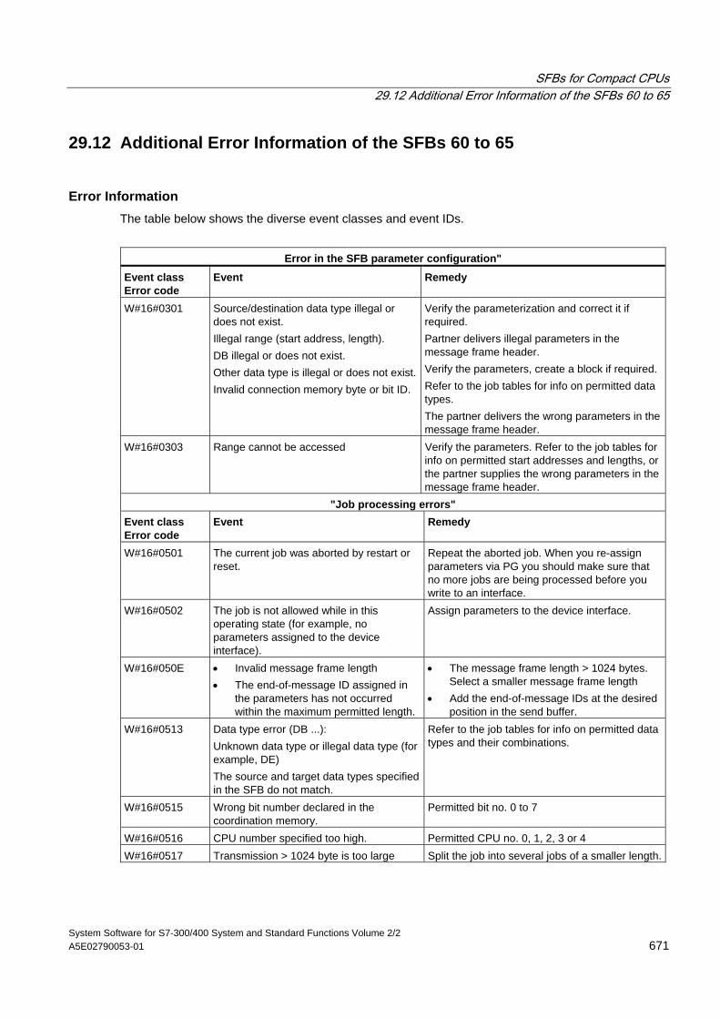
SFBs for Compact CPUs 29.12 Additional Error Information of the SFBs 60 to 65
System Software for S7-300/400 System and Standard Functions Volume 2/2 A5E02790053-01 671
29.12 Additional Error Information of the SFBs 60 to 65
Error Information The table below shows the diverse event classes and event IDs.
Error in the SFB parameter configuration"
Event class Error code
Event Remedy
W#16#0301 Source/destination data type illegal or does not exist. Illegal range (start address, length). DB illegal or does not exist. Other data type is illegal or does not exist.Invalid connection memory byte or bit ID.
Verify the parameterization and correct it if required. Partner delivers illegal parameters in the message frame header. Verify the parameters, create a block if required. Refer to the job tables for info on permitted data types. The partner delivers the wrong parameters in the message frame header.
W#16#0303 Range cannot be accessed Verify the parameters. Refer to the job tables for info on permitted start addresses and lengths, or the partner supplies the wrong parameters in the message frame header.
"Job processing errors" Event class Error code
Event Remedy
W#16#0501 The current job was aborted by restart or reset.
Repeat the aborted job. When you re-assign parameters via PG you should make sure that no more jobs are being processed before you write to an interface.
W#16#0502 The job is not allowed while in this operating state (for example, no parameters assigned to the device interface).
Assign parameters to the device interface.
W#16#050E • Invalid message frame length • The end-of-message ID assigned in
the parameters has not occurred within the maximum permitted length.
• The message frame length > 1024 bytes. Select a smaller message frame length
• Add the end-of-message IDs at the desired position in the send buffer.
W#16#0513 Data type error (DB ...): Unknown data type or illegal data type (for example, DE) The source and target data types specified in the SFB do not match.
Refer to the job tables for info on permitted data types and their combinations.
W#16#0515 Wrong bit number declared in the coordination memory.
Permitted bit no. 0 to 7
W#16#0516 CPU number specified too high. Permitted CPU no. 0, 1, 2, 3 or 4 W#16#0517 Transmission > 1024 byte is too large Split the job into several jobs of a smaller length.
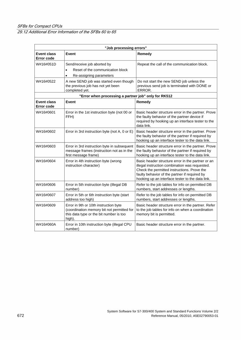
SFBs for Compact CPUs 29.12 Additional Error Information of the SFBs 60 to 65
System Software for S7-300/400 System and Standard Functions Volume 2/2 672 Reference Manual, 05/2010, A5E02790053-01
"Job processing errors" Event class Error code
Event Remedy
W#16#051D Send/receive job aborted by • Reset of the communication block • Re-assigning parameters
Repeat the call of the communication block.
W#16#0522 A new SEND job was started even though the previous job has not yet been completed yet.
Do not start the new SEND job unless the previous send job is terminated with DONE or ERROR.
"Error when processing a partner job" only for RK512 Event class Error code
Event Remedy
W#16#0601 Error in the 1st instruction byte (not 00 or FFH)
Basic header structure error in the partner. Prove the faulty behavior of the partner device if required by hooking up an interface tester to the data link.
W#16#0602 Error in 3rd instruction byte (not A, 0 or E) Basic header structure error in the partner. Prove the faulty behavior of the partner if required by hooking up an interface tester to the data link.
W#16#0603 Error in 3rd instruction byte in subsequent message frames (instruction not as in the first message frame)
Basic header structure error in the partner. Prove the faulty behavior of the partner if required by hooking up an interface tester to the data link.
W#16#0604 Error in 4th instruction byte (wrong instruction character)
Basic header structure error in the partner or an illegal instruction combination was requested. Check the permitted instructions. Prove the faulty behavior of the partner if required by hooking up an interface tester to the data link.
W#16#0606 Error in 5th instruction byte (illegal DB number)
Refer to the job tables for info on permitted DB numbers, start addresses or lengths.
W#16#0607 Error in 5th or 6th instruction byte (start address too high)
Refer to the job tables for info on permitted DB numbers, start addresses or lengths.
W#16#0609 Error in 9th or 10th instruction byte (coordination memory bit not permitted for this data type or the bit number is too high).
Basic header structure error in the partner. Refer to the job tables for info on when a coordination memory bit is permitted.
W#16#060A Error in 10th instruction byte (illegal CPU number)
Basic header structure error in the partner.
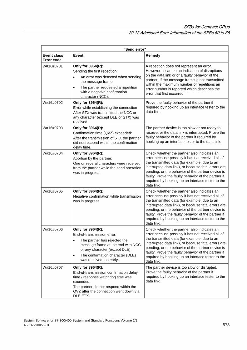
SFBs for Compact CPUs 29.12 Additional Error Information of the SFBs 60 to 65
System Software for S7-300/400 System and Standard Functions Volume 2/2 A5E02790053-01 673
"Send error" Event class Error code
Event Remedy
W#16#0701 Only for 3964(R): Sending the first repetition: • An error was detected when sending
the message frame • The partner requested a repetition
with a negative confirmation character (NCC).
A repetition does not represent an error. However, it can be an indication of disruptions on the data link or of a faulty behavior of the partner. If the message frame is not transmitted within the maximum number of repetitions an error number is reported which describes the error that first occurred.
W#16#0702 Only for 3964(R): Error while establishing the connection After STX was transmitted the NCC or any character (except DLE or STX) was received.
Prove the faulty behavior of the partner if required by hooking up an interface tester to the data link.
W#16#0703 Only for 3964(R): Confirmation time (QVZ) exceeded: After the transmission of STX the partner did not respond within the confirmation delay time.
The partner device is too slow or not ready to receive, or the data link is interrupted. Prove the faulty behavior of the partner if required by hooking up an interface tester to the data link.
W#16#0704 Only for 3964(R): Abortion by the partner: One or several characters were received from the partner while the send operation was in progress.
Check whether the partner also indicates an error because possibly it has not received all of the transmitted data (for example, due to an interrupted data link), or because fatal errors are pending, or the behavior of the partner device is faulty. Prove the faulty behavior of the partner if required by hooking up an interface tester to the data link.
W#16#0705 Only for 3964(R): Negative confirmation while transmission was in progress
Check whether the partner also indicates an error because possibly it has not received all of the transmitted data (for example, due to an interrupted data link), or because fatal errors are pending, or the behavior of the partner device is faulty. Prove the faulty behavior of the partner if required by hooking up an interface tester to the data link.
W#16#0706 Only for 3964(R): End-of-transmission error: • The partner has rejected the
message frame at the end with NCC or any character (except DLE)
• The confirmation character (DLE) was received too early.
Check whether the partner also indicates an error because possibly it has not received all of the transmitted data (for example, due to an interrupted data link), or because fatal errors are pending, or the behavior of the partner device is faulty. Prove the faulty behavior of the partner if required by hooking up an interface tester to the data link.
W#16#0707 Only for 3964(R): End-of-transmission confirmation delay time / response watchdog time was exceeded: The partner did not respond within the QVZ after the connection went down via DLE ETX.
The partner device is too slow or disrupted. Prove the faulty behavior of the partner if required by hooking up an interface tester to the data link.
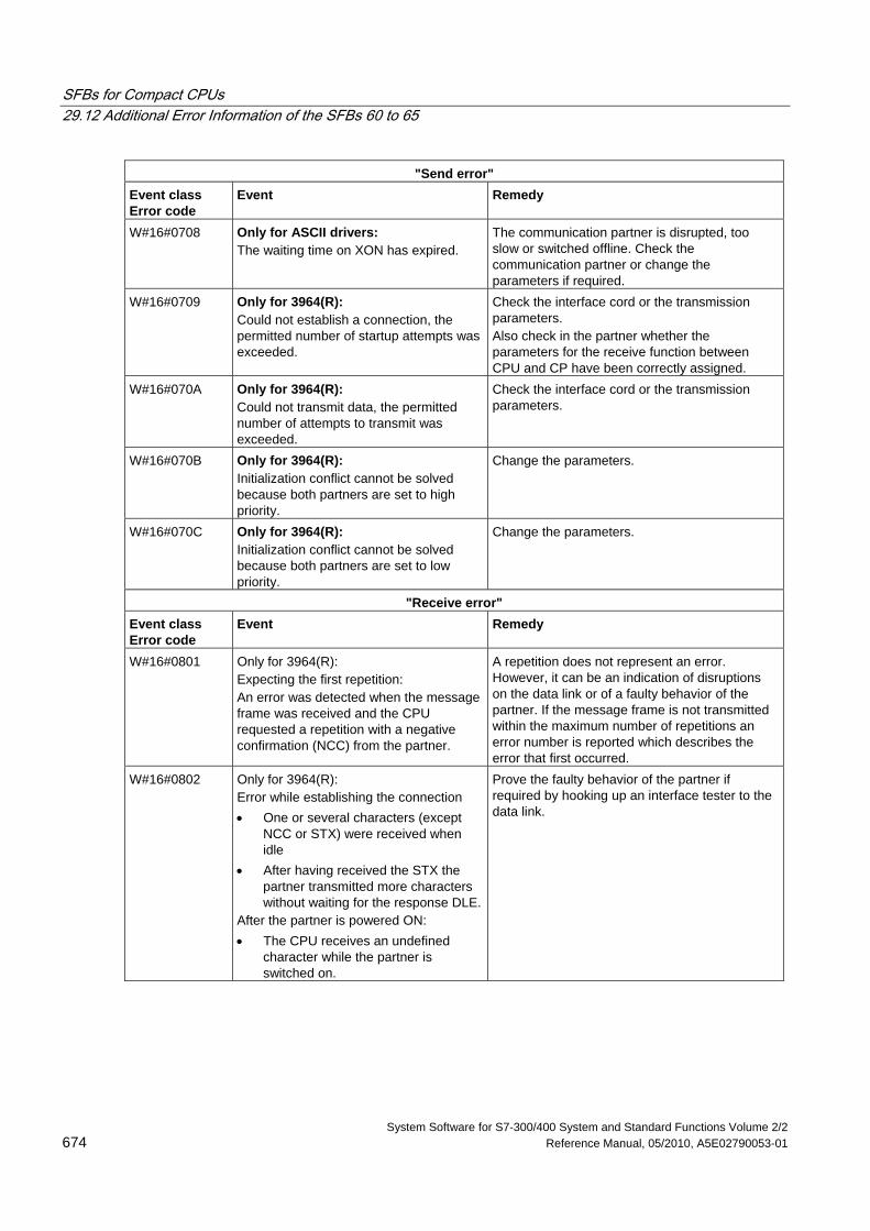
SFBs for Compact CPUs 29.12 Additional Error Information of the SFBs 60 to 65
System Software for S7-300/400 System and Standard Functions Volume 2/2 674 Reference Manual, 05/2010, A5E02790053-01
"Send error" Event class Error code
Event Remedy
W#16#0708 Only for ASCII drivers: The waiting time on XON has expired.
The communication partner is disrupted, too slow or switched offline. Check the communication partner or change the parameters if required.
W#16#0709 Only for 3964(R): Could not establish a connection, the permitted number of startup attempts was exceeded.
Check the interface cord or the transmission parameters. Also check in the partner whether the parameters for the receive function between CPU and CP have been correctly assigned.
W#16#070A Only for 3964(R): Could not transmit data, the permitted number of attempts to transmit was exceeded.
Check the interface cord or the transmission parameters.
W#16#070B Only for 3964(R): Initialization conflict cannot be solved because both partners are set to high priority.
Change the parameters.
W#16#070C Only for 3964(R): Initialization conflict cannot be solved because both partners are set to low priority.
Change the parameters.
"Receive error" Event class Error code
Event Remedy
W#16#0801 Only for 3964(R): Expecting the first repetition: An error was detected when the message frame was received and the CPU requested a repetition with a negative confirmation (NCC) from the partner.
A repetition does not represent an error. However, it can be an indication of disruptions on the data link or of a faulty behavior of the partner. If the message frame is not transmitted within the maximum number of repetitions an error number is reported which describes the error that first occurred.
W#16#0802 Only for 3964(R): Error while establishing the connection • One or several characters (except
NCC or STX) were received when idle
• After having received the STX the partner transmitted more characters without waiting for the response DLE.
After the partner is powered ON: • The CPU receives an undefined
character while the partner is switched on.
Prove the faulty behavior of the partner if required by hooking up an interface tester to the data link.
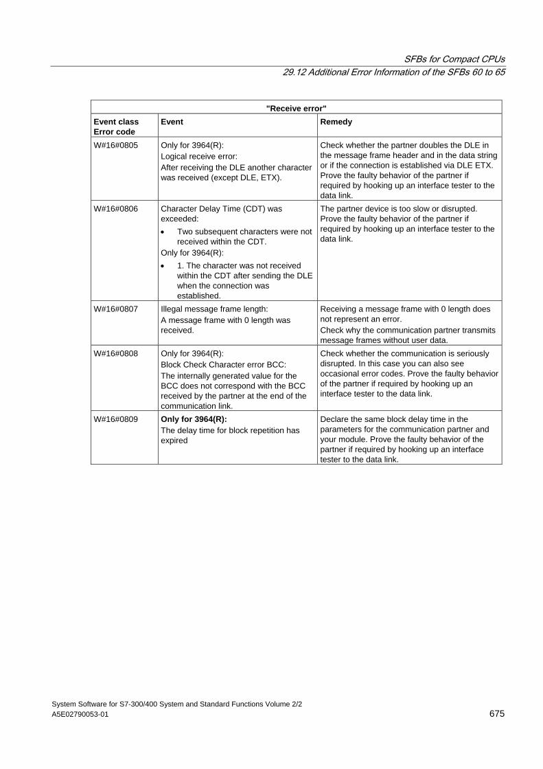
SFBs for Compact CPUs 29.12 Additional Error Information of the SFBs 60 to 65
System Software for S7-300/400 System and Standard Functions Volume 2/2 A5E02790053-01 675
"Receive error" Event class Error code
Event Remedy
W#16#0805 Only for 3964(R): Logical receive error: After receiving the DLE another character was received (except DLE, ETX).
Check whether the partner doubles the DLE in the message frame header and in the data string or if the connection is established via DLE ETX. Prove the faulty behavior of the partner if required by hooking up an interface tester to the data link.
W#16#0806 Character Delay Time (CDT) was exceeded: • Two subsequent characters were not
received within the CDT. Only for 3964(R): • 1. The character was not received
within the CDT after sending the DLE when the connection was established.
The partner device is too slow or disrupted. Prove the faulty behavior of the partner if required by hooking up an interface tester to the data link.
W#16#0807 Illegal message frame length: A message frame with 0 length was received.
Receiving a message frame with 0 length does not represent an error. Check why the communication partner transmits message frames without user data.
W#16#0808 Only for 3964(R): Block Check Character error BCC: The internally generated value for the BCC does not correspond with the BCC received by the partner at the end of the communication link.
Check whether the communication is seriously disrupted. In this case you can also see occasional error codes. Prove the faulty behavior of the partner if required by hooking up an interface tester to the data link.
W#16#0809 Only for 3964(R): The delay time for block repetition has expired
Declare the same block delay time in the parameters for the communication partner and your module. Prove the faulty behavior of the partner if required by hooking up an interface tester to the data link.
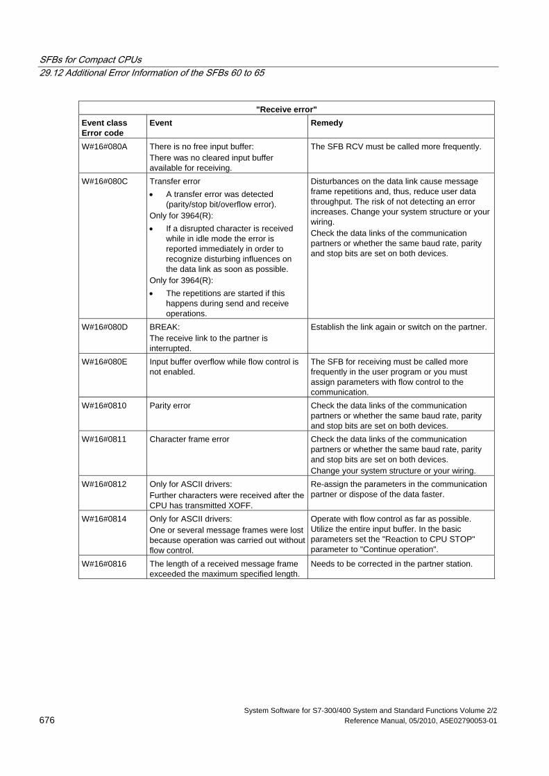
SFBs for Compact CPUs 29.12 Additional Error Information of the SFBs 60 to 65
System Software for S7-300/400 System and Standard Functions Volume 2/2 676 Reference Manual, 05/2010, A5E02790053-01
"Receive error" Event class Error code
Event Remedy
W#16#080A There is no free input buffer: There was no cleared input buffer available for receiving.
The SFB RCV must be called more frequently.
W#16#080C Transfer error • A transfer error was detected
(parity/stop bit/overflow error). Only for 3964(R): • If a disrupted character is received
while in idle mode the error is reported immediately in order to recognize disturbing influences on the data link as soon as possible.
Only for 3964(R): • The repetitions are started if this
happens during send and receive operations.
Disturbances on the data link cause message frame repetitions and, thus, reduce user data throughput. The risk of not detecting an error increases. Change your system structure or your wiring. Check the data links of the communication partners or whether the same baud rate, parity and stop bits are set on both devices.
W#16#080D BREAK: The receive link to the partner is interrupted.
Establish the link again or switch on the partner.
W#16#080E Input buffer overflow while flow control is not enabled.
The SFB for receiving must be called more frequently in the user program or you must assign parameters with flow control to the communication.
W#16#0810 Parity error Check the data links of the communication partners or whether the same baud rate, parity and stop bits are set on both devices.
W#16#0811 Character frame error Check the data links of the communication partners or whether the same baud rate, parity and stop bits are set on both devices. Change your system structure or your wiring.
W#16#0812 Only for ASCII drivers: Further characters were received after the CPU has transmitted XOFF.
Re-assign the parameters in the communication partner or dispose of the data faster.
W#16#0814 Only for ASCII drivers: One or several message frames were lost because operation was carried out without flow control.
Operate with flow control as far as possible. Utilize the entire input buffer. In the basic parameters set the "Reaction to CPU STOP" parameter to "Continue operation".
W#16#0816 The length of a received message frame exceeded the maximum specified length.
Needs to be corrected in the partner station.
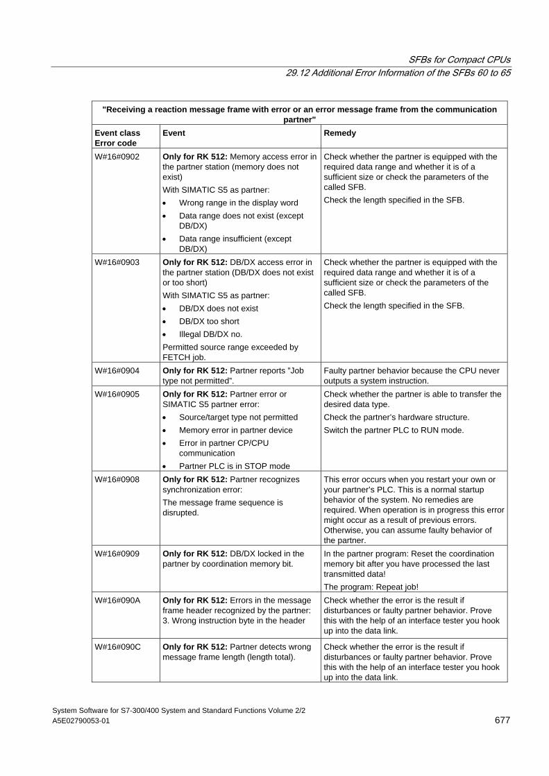
SFBs for Compact CPUs 29.12 Additional Error Information of the SFBs 60 to 65
System Software for S7-300/400 System and Standard Functions Volume 2/2 A5E02790053-01 677
"Receiving a reaction message frame with error or an error message frame from the communication partner"
Event class Error code
Event Remedy
W#16#0902 Only for RK 512: Memory access error in the partner station (memory does not exist) With SIMATIC S5 as partner: • Wrong range in the display word • Data range does not exist (except
DB/DX) • Data range insufficient (except
DB/DX)
Check whether the partner is equipped with the required data range and whether it is of a sufficient size or check the parameters of the called SFB. Check the length specified in the SFB.
W#16#0903 Only for RK 512: DB/DX access error in the partner station (DB/DX does not exist or too short) With SIMATIC S5 as partner: • DB/DX does not exist • DB/DX too short • Illegal DB/DX no. Permitted source range exceeded by FETCH job.
Check whether the partner is equipped with the required data range and whether it is of a sufficient size or check the parameters of the called SFB. Check the length specified in the SFB.
W#16#0904 Only for RK 512: Partner reports ”Job type not permitted”.
Faulty partner behavior because the CPU never outputs a system instruction.
W#16#0905 Only for RK 512: Partner error or SIMATIC S5 partner error: • Source/target type not permitted • Memory error in partner device • Error in partner CP/CPU
communication • Partner PLC is in STOP mode
Check whether the partner is able to transfer the desired data type. Check the partner’s hardware structure. Switch the partner PLC to RUN mode.
W#16#0908 Only for RK 512: Partner recognizes synchronization error: The message frame sequence is disrupted.
This error occurs when you restart your own or your partner’s PLC. This is a normal startup behavior of the system. No remedies are required. When operation is in progress this error might occur as a result of previous errors. Otherwise, you can assume faulty behavior of the partner.
W#16#0909 Only for RK 512: DB/DX locked in the partner by coordination memory bit.
In the partner program: Reset the coordination memory bit after you have processed the last transmitted data! The program: Repeat job!
W#16#090A Only for RK 512: Errors in the message frame header recognized by the partner: 3. Wrong instruction byte in the header
Check whether the error is the result if disturbances or faulty partner behavior. Prove this with the help of an interface tester you hook up into the data link.
W#16#090C Only for RK 512: Partner detects wrong message frame length (length total).
Check whether the error is the result if disturbances or faulty partner behavior. Prove this with the help of an interface tester you hook up into the data link.
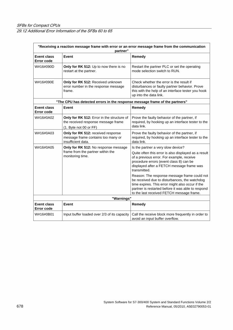
SFBs for Compact CPUs 29.12 Additional Error Information of the SFBs 60 to 65
System Software for S7-300/400 System and Standard Functions Volume 2/2 678 Reference Manual, 05/2010, A5E02790053-01
"Receiving a reaction message frame with error or an error message frame from the communication partner"
Event class Error code
Event Remedy
W#16#090D Only for RK 512: Up to now there is no restart at the partner.
Restart the partner PLC or set the operating mode selection switch to RUN.
W#16#090E Only for RK 512: Received unknown error number in the response message frame.
Check whether the error is the result if disturbances or faulty partner behavior. Prove this with the help of an interface tester you hook up into the data link.
"The CPU has detected errors in the response message frame of the partners" Event class Error code
Event Remedy
W#16#0A02 Only for RK 512: Error in the structure of the received response message frame (1. Byte not 00 or FF)
Prove the faulty behavior of the partner, if required, by hooking up an interface tester to the data link.
W#16#0A03 Only for RK 512: received response message frame contains too many or insufficient data.
Prove the faulty behavior of the partner, if required, by hooking up an interface tester to the data link.
W#16#0A05 Only for RK 512: No response message frame from the partner within the monitoring time.
Is the partner a very slow device? Quite often this error is also displayed as a result of a previous error. For example, receive procedure errors (event class 8) can be displayed after a FETCH message frame was transmitted. Reason: The response message frame could not be received due to disturbances, the watchdog time expires. This error might also occur if the partner is restarted before it was able to respond to the last received FETCH message frame.
"Warnings" Event class Error code
Event Remedy
W#16#0B01 Input buffer loaded over 2/3 of its capacity Call the receive block more frequently in order to avoid an input buffer overflow.
System Software for S7-300/400 System and Standard Functions Volume 2/2 Reference Manual, 05/2010, A5E02790053-01 679
30 SFCs for H CPUs
30.1 Controlling Operation in H Systems with SFC 90 "H_CTRL"
Description With SFC 90 "H_CTRL," you can influence H systems as follows:
• You can prevent the standby link-up in the master CPU. This is then disabled until you cancel the setting with SFC 90 "H_CTRL" or the H system goes into STOP mode.
Any request from the standby CPU to link-up with the master is stored.
• You can disable updating on the master CPU. This is then disabled until you cancel the setting with SFC 90 "H_CTRL" or the H system goes into STOP mode.
Any request from the standby CPU to update is stored.
! Caution If you have disabled update but not connect, the hardware system still can determine the connection status as before. Please note that when the master CPU is connecting, it does not process any remove/insert interrupts, station failure/returned interrupts or rack failure/returned interrupts.
• You can remove a test component from the cyclical self-test, add it again or start immediately. If you have disabled one or more test components of the cyclical self test, the component or components remain disabled until you cancel the setting with SFC 90 "H_CTRL" or the H system goes into STOP mode. Note: If you use a CPU 414-4H or 417-4H in a redundant system, please observe the following: If you disable the component for more than 24 hours, the CPU goes into STOP mode. For redundant systems, the applicable regulation states that certain tests must be completed within 24 hours.
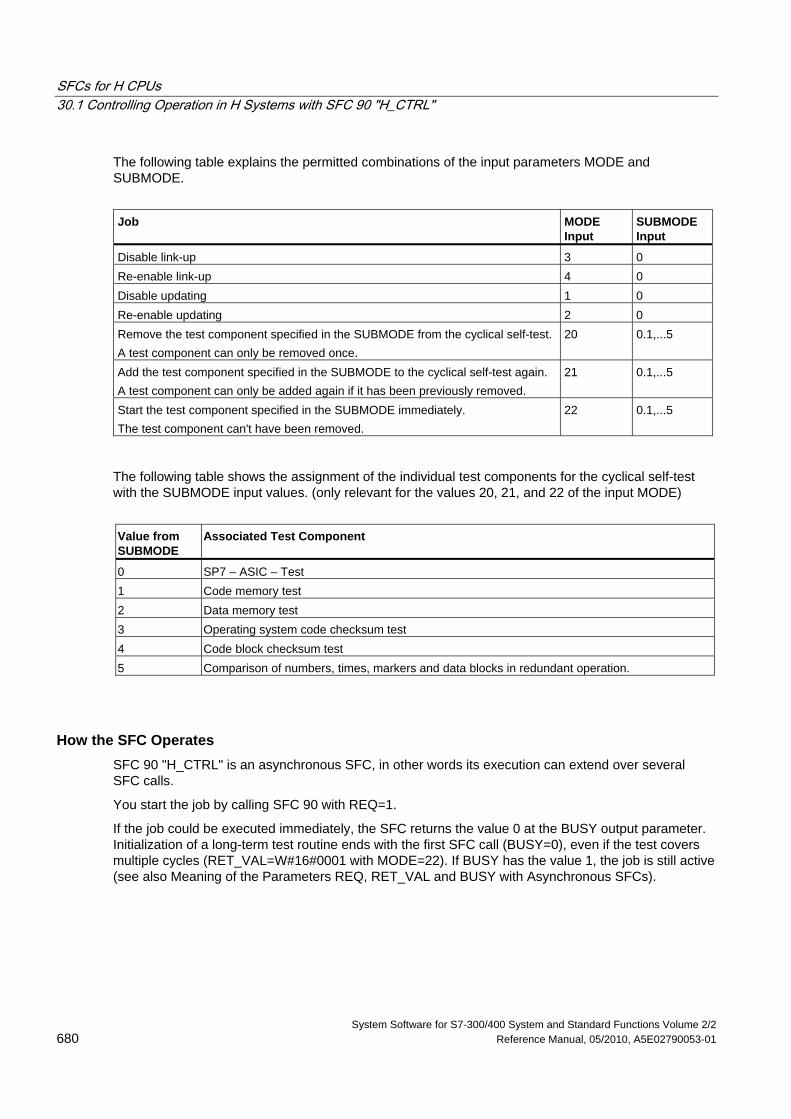
SFCs for H CPUs 30.1 Controlling Operation in H Systems with SFC 90 "H_CTRL"
System Software for S7-300/400 System and Standard Functions Volume 2/2 680 Reference Manual, 05/2010, A5E02790053-01
The following table explains the permitted combinations of the input parameters MODE and SUBMODE.
Job
MODE Input
SUBMODE Input
Disable link-up 3 0 Re-enable link-up 4 0 Disable updating 1 0 Re-enable updating 2 0 Remove the test component specified in the SUBMODE from the cyclical self-test. A test component can only be removed once.
20 0.1,...5
Add the test component specified in the SUBMODE to the cyclical self-test again. A test component can only be added again if it has been previously removed.
21 0.1,...5
Start the test component specified in the SUBMODE immediately. The test component can't have been removed.
22 0.1,...5
The following table shows the assignment of the individual test components for the cyclical self-test with the SUBMODE input values. (only relevant for the values 20, 21, and 22 of the input MODE)
Value from SUBMODE
Associated Test Component
0 SP7 – ASIC – Test 1 Code memory test 2 Data memory test 3 Operating system code checksum test 4 Code block checksum test 5 Comparison of numbers, times, markers and data blocks in redundant operation.
How the SFC Operates SFC 90 "H_CTRL" is an asynchronous SFC, in other words its execution can extend over several SFC calls.
You start the job by calling SFC 90 with REQ=1.
If the job could be executed immediately, the SFC returns the value 0 at the BUSY output parameter. Initialization of a long-term test routine ends with the first SFC call (BUSY=0), even if the test covers multiple cycles (RET_VAL=W#16#0001 with MODE=22). If BUSY has the value 1, the job is still active (see also Meaning of the Parameters REQ, RET_VAL and BUSY with Asynchronous SFCs).
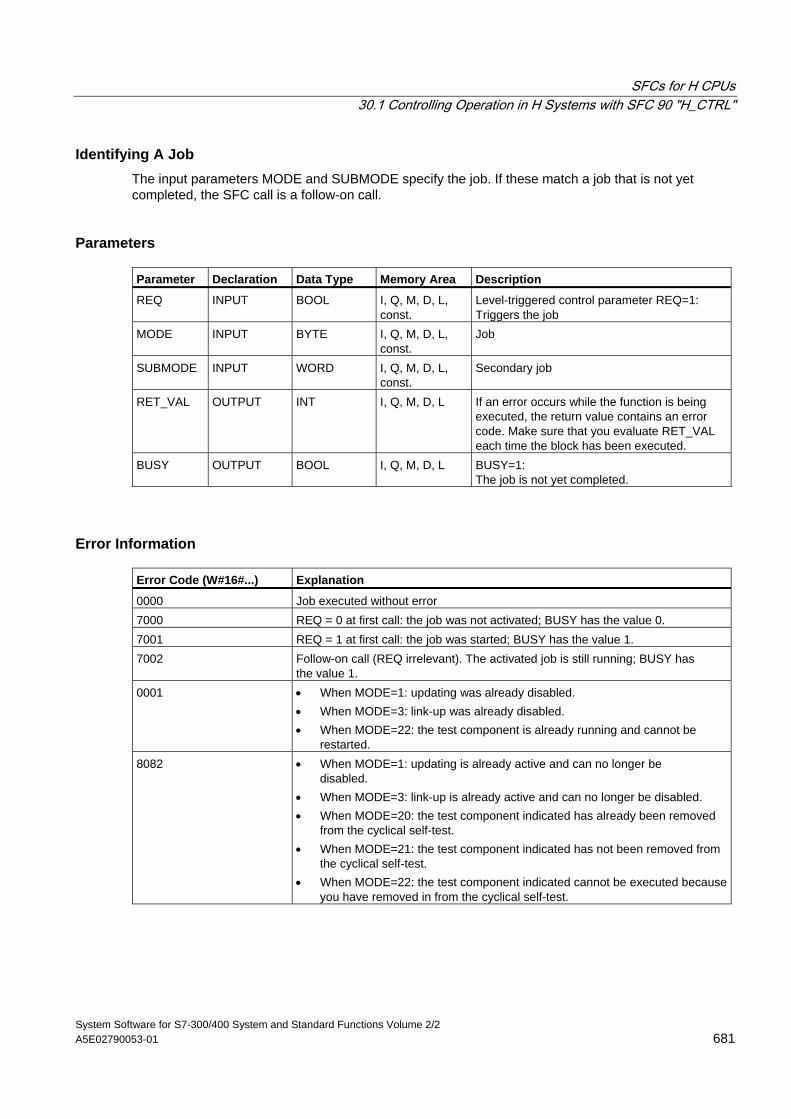
SFCs for H CPUs 30.1 Controlling Operation in H Systems with SFC 90 "H_CTRL"
System Software for S7-300/400 System and Standard Functions Volume 2/2 A5E02790053-01 681
Identifying A Job The input parameters MODE and SUBMODE specify the job. If these match a job that is not yet completed, the SFC call is a follow-on call.
Parameters Parameter Declaration Data Type Memory Area Description
REQ INPUT BOOL I, Q, M, D, L, const.
Level-triggered control parameter REQ=1: Triggers the job
MODE INPUT BYTE I, Q, M, D, L, const.
Job
SUBMODE INPUT WORD I, Q, M, D, L, const.
Secondary job
RET_VAL OUTPUT INT I, Q, M, D, L If an error occurs while the function is being executed, the return value contains an error code. Make sure that you evaluate RET_VAL each time the block has been executed.
BUSY OUTPUT BOOL I, Q, M, D, L BUSY=1: The job is not yet completed.
Error Information Error Code (W#16#...) Explanation
0000 Job executed without error 7000 REQ = 0 at first call: the job was not activated; BUSY has the value 0. 7001 REQ = 1 at first call: the job was started; BUSY has the value 1. 7002 Follow-on call (REQ irrelevant). The activated job is still running; BUSY has
the value 1. 0001 • When MODE=1: updating was already disabled.
• When MODE=3: link-up was already disabled. • When MODE=22: the test component is already running and cannot be
restarted. 8082 • When MODE=1: updating is already active and can no longer be
disabled. • When MODE=3: link-up is already active and can no longer be disabled. • When MODE=20: the test component indicated has already been removed
from the cyclical self-test. • When MODE=21: the test component indicated has not been removed from
the cyclical self-test. • When MODE=22: the test component indicated cannot be executed because
you have removed in from the cyclical self-test.
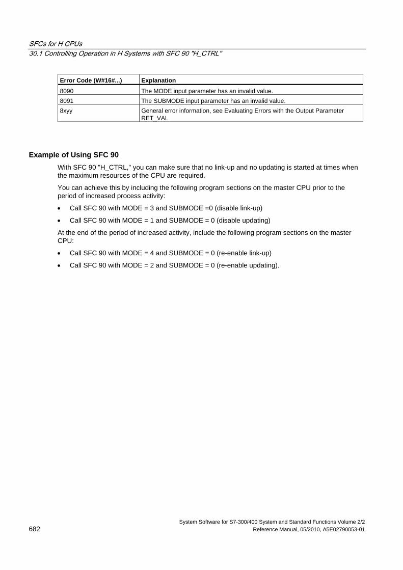
SFCs for H CPUs 30.1 Controlling Operation in H Systems with SFC 90 "H_CTRL"
System Software for S7-300/400 System and Standard Functions Volume 2/2 682 Reference Manual, 05/2010, A5E02790053-01
Error Code (W#16#...) Explanation
8090 The MODE input parameter has an invalid value. 8091 The SUBMODE input parameter has an invalid value. 8xyy General error information, see Evaluating Errors with the Output Parameter
RET_VAL
Example of Using SFC 90 With SFC 90 "H_CTRL," you can make sure that no link-up and no updating is started at times when the maximum resources of the CPU are required.
You can achieve this by including the following program sections on the master CPU prior to the period of increased process activity:
• Call SFC 90 with MODE = 3 and SUBMODE =0 (disable link-up)
• Call SFC 90 with MODE = 1 and SUBMODE = 0 (disable updating)
At the end of the period of increased activity, include the following program sections on the master CPU:
• Call SFC 90 with MODE = 4 and SUBMODE = 0 (re-enable link-up)
• Call SFC 90 with MODE = 2 and SUBMODE = 0 (re-enable updating).
System Software for S7-300/400 System and Standard Functions Volume 2/2 Reference Manual, 05/2010, A5E02790053-01 683
31 Integrated Functions (for CPUs with integrated I/Os)
31.1 SFB 29 (HS_COUNT)
Description With SFB 29 "HS_COUNT" (counter), you can influence the integrated counter function of a CPU with integrated I/Os, as follows:
• Set and enter a start value.
• Select and set comparison values.
• Enable counters.
• Enable digital outputs.
• Read current counted values and current comparison values.
• Query the relationship between the counted value and the comparison value.
Further Information The meaning of the individual parameters of SFB 29 in conjunction with the parameters for the integrated function counter and the hardware inputs and outputs of the CPU is described in detail in S7-300 Programmable Controller, Integrated Functions manual.
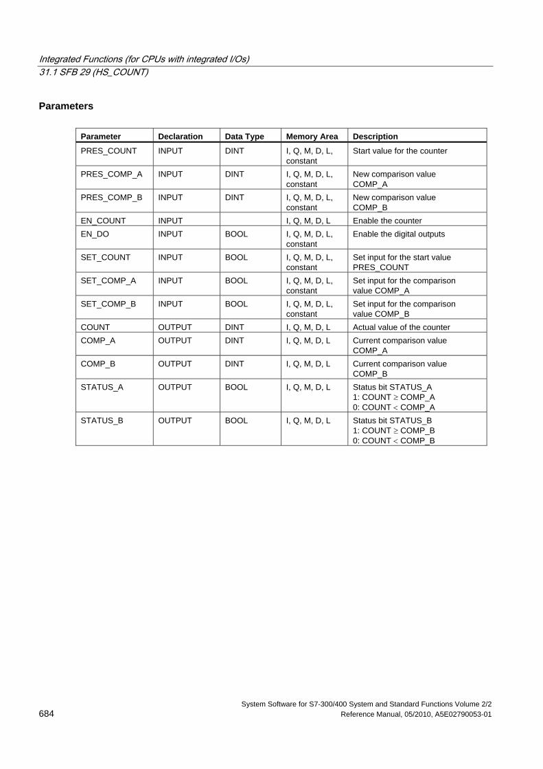
Integrated Functions (for CPUs with integrated I/Os) 31.1 SFB 29 (HS_COUNT)
System Software for S7-300/400 System and Standard Functions Volume 2/2 684 Reference Manual, 05/2010, A5E02790053-01
Parameters Parameter Declaration Data Type Memory Area Description
PRES_COUNT INPUT DINT I, Q, M, D, L, constant
Start value for the counter
PRES_COMP_A INPUT DINT I, Q, M, D, L, constant
New comparison value COMP_A
PRES_COMP_B INPUT DINT I, Q, M, D, L, constant
New comparison value COMP_B
EN_COUNT INPUT I, Q, M, D, L Enable the counter EN_DO INPUT BOOL I, Q, M, D, L,
constant Enable the digital outputs
SET_COUNT INPUT BOOL I, Q, M, D, L, constant
Set input for the start value PRES_COUNT
SET_COMP_A INPUT BOOL I, Q, M, D, L, constant
Set input for the comparison value COMP_A
SET_COMP_B INPUT BOOL I, Q, M, D, L, constant
Set input for the comparison value COMP_B
COUNT OUTPUT DINT I, Q, M, D, L Actual value of the counter COMP_A OUTPUT DINT I, Q, M, D, L Current comparison value
COMP_A COMP_B OUTPUT DINT I, Q, M, D, L Current comparison value
COMP_B STATUS_A OUTPUT BOOL I, Q, M, D, L Status bit STATUS_A
1: COUNT ≥ COMP_A 0: COUNT < COMP_A
STATUS_B OUTPUT BOOL I, Q, M, D, L Status bit STATUS_B 1: COUNT ≥ COMP_B 0: COUNT < COMP_B
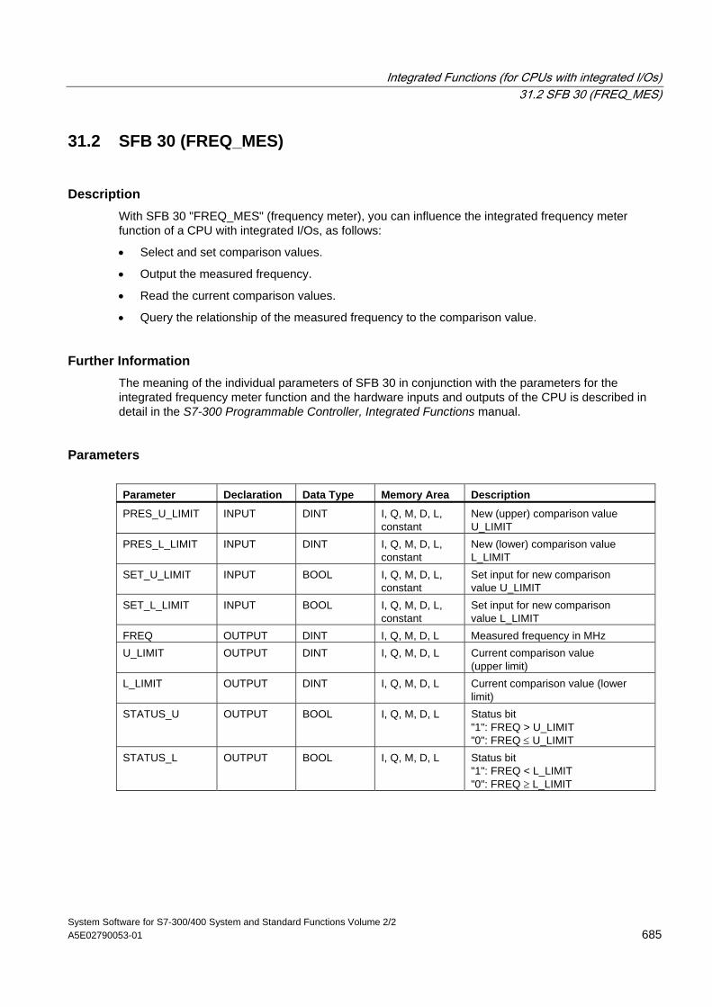
Integrated Functions (for CPUs with integrated I/Os) 31.2 SFB 30 (FREQ_MES)
System Software for S7-300/400 System and Standard Functions Volume 2/2 A5E02790053-01 685
31.2 SFB 30 (FREQ_MES)
Description With SFB 30 "FREQ_MES" (frequency meter), you can influence the integrated frequency meter function of a CPU with integrated I/Os, as follows:
• Select and set comparison values.
• Output the measured frequency.
• Read the current comparison values.
• Query the relationship of the measured frequency to the comparison value.
Further Information The meaning of the individual parameters of SFB 30 in conjunction with the parameters for the integrated frequency meter function and the hardware inputs and outputs of the CPU is described in detail in the S7-300 Programmable Controller, Integrated Functions manual.
Parameters Parameter Declaration Data Type Memory Area Description
PRES_U_LIMIT INPUT DINT I, Q, M, D, L, constant
New (upper) comparison value U_LIMIT
PRES_L_LIMIT INPUT DINT I, Q, M, D, L, constant
New (lower) comparison value L_LIMIT
SET_U_LIMIT INPUT BOOL I, Q, M, D, L, constant
Set input for new comparison value U_LIMIT
SET_L_LIMIT INPUT BOOL I, Q, M, D, L, constant
Set input for new comparison value L_LIMIT
FREQ OUTPUT DINT I, Q, M, D, L Measured frequency in MHz U_LIMIT OUTPUT DINT I, Q, M, D, L Current comparison value
(upper limit) L_LIMIT OUTPUT DINT I, Q, M, D, L Current comparison value (lower
limit) STATUS_U OUTPUT BOOL I, Q, M, D, L Status bit
"1": FREQ > U_LIMIT "0": FREQ ≤ U_LIMIT
STATUS_L OUTPUT BOOL I, Q, M, D, L Status bit "1": FREQ < L_LIMIT "0": FREQ ≥ L_LIMIT
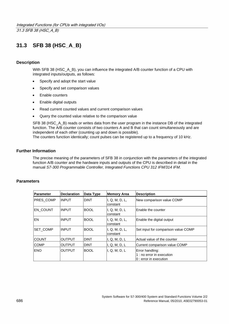
Integrated Functions (for CPUs with integrated I/Os) 31.3 SFB 38 (HSC_A_B)
System Software for S7-300/400 System and Standard Functions Volume 2/2 686 Reference Manual, 05/2010, A5E02790053-01
31.3 SFB 38 (HSC_A_B)
Description With SFB 38 (HSC_A_B), you can influence the integrated A/B counter function of a CPU with integrated inputs/outputs, as follows:
• Specify and adopt the start value
• Specify and set comparison values
• Enable counters
• Enable digital outputs
• Read current counted values and current comparison values
• Query the counted value relative to the comparison value
SFB 38 (HSC_A_B) reads or writes data from the user program in the instance DB of the integrated function. The A/B counter consists of two counters A and B that can count simultaneously and are independent of each other (counting up and down is possible). The counters function identically; count pulses can be registered up to a frequency of 10 kHz.
Further Information The precise meaning of the parameters of SFB 38 in conjunction with the parameters of the integrated function A/B counter and the hardware inputs and outputs of the CPU is described in detail in the manual S7-300 Programmable Controller, Integrated Functions CPU 312 IFM/314 IFM.
Parameters Parameter Declaration Data Type Memory Area Description
PRES_COMP INPUT DINT I, Q, M, D, L, constant
New comparison value COMP
EN_COUNT INPUT BOOL I, Q, M, D, L constant
Enable the counter
EN INPUT BOOL I, Q, M, D, L, constant
Enable the digital output
SET_COMP INPUT BOOL I, Q, M, D, L, constant
Set input for comparison value COMP
COUNT OUTPUT DINT I, Q, M, D, L Actual value of the counter COMP OUTPUT DINT I, Q, M, D, L Current comparison value COMP ENO OUTPUT BOOL I, Q, M, D, L Error handling:
1 : no error in execution 0 : error in execution
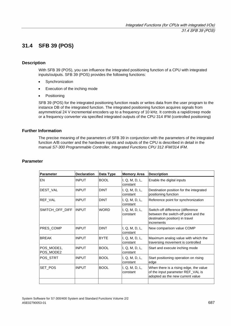
Integrated Functions (for CPUs with integrated I/Os) 31.4 SFB 39 (POS)
System Software for S7-300/400 System and Standard Functions Volume 2/2 A5E02790053-01 687
31.4 SFB 39 (POS)
Description With SFB 39 (POS), you can influence the integrated positioning function of a CPU with integrated inputs/outputs. SFB 39 (POS) provides the following functions:
• Synchronization
• Execution of the inching mode
• Positioning
SFB 39 (POS) for the integrated positioning function reads or writes data from the user program to the instance DB of the integrated function. The integrated positioning function acquires signals from asymmetrical 24 V incremental encoders up to a frequency of 10 kHz. It controls a rapid/creep mode or a frequency converter via specified integrated outputs of the CPU 314 IFM (controlled positioning)
Further Information The precise meaning of the parameters of SFB 39 in conjunction with the parameters of the integrated function A/B counter and the hardware inputs and outputs of the CPU is described in detail in the manual S7-300 Programmable Controller, Integrated Functions CPU 312 IFM/314 IFM.
Parameter Parameter Declaration Data Type Memory Area Description
EN INPUT BOOL I, Q, M, D, L, constant
Enable the digital inputs
DEST_VAL INPUT DINT I, Q, M, D, L, constant
Destination position for the integrated positioning function
REF_VAL INPUT DINT I, Q, M, D, L, constant
Reference point for synchronization
SWITCH_OFF_DIFF INPUT WORD I, Q, M, D, L, constant
Switch-off difference (difference between the switch-off point and the destination position) in travel increments
PRES_COMP INPUT DINT I, Q, M, D, L, constant
New comparison value COMP
BREAK INPUT BYTE I, Q, M, D, L, constant
Maximum analog value with which the traversing movement is controlled
POS_MODE1, POS_MODE2
INPUT BOOL I, Q, M, D, L, constant
Start and execute inching mode
POS_STRT INPUT BOOL I, Q, M, D, L, constant
Start positioning operation on rising edge
SET_POS INPUT BOOL I, Q, M, D, L, constant
When there is a rising edge, the value of the input parameter REF_VAL is adopted as the new current value
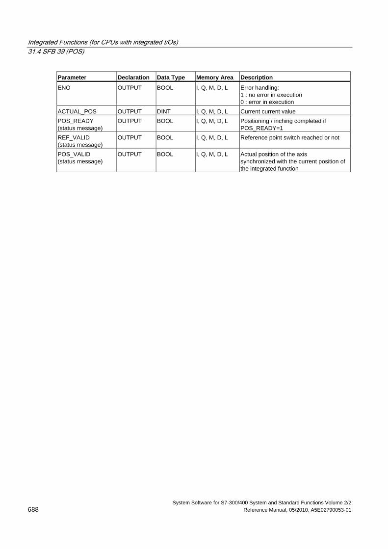
Integrated Functions (for CPUs with integrated I/Os) 31.4 SFB 39 (POS)
System Software for S7-300/400 System and Standard Functions Volume 2/2 688 Reference Manual, 05/2010, A5E02790053-01
Parameter Declaration Data Type Memory Area Description
ENO OUTPUT BOOL I, Q, M, D, L Error handling: 1 : no error in execution 0 : error in execution
ACTUAL_POS OUTPUT DINT I, Q, M, D, L Current current value POS_READY (status message)
OUTPUT BOOL I, Q, M, D, L Positioning / inching completed if POS_READY=1
REF_VALID (status message)
OUTPUT BOOL I, Q, M, D, L Reference point switch reached or not
POS_VALID (status message)
OUTPUT BOOL I, Q, M, D, L Actual position of the axis synchronized with the current position of the integrated function
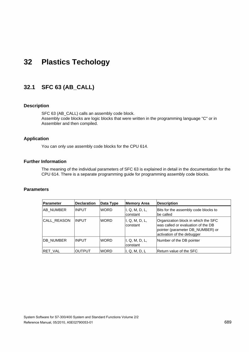
System Software for S7-300/400 System and Standard Functions Volume 2/2 Reference Manual, 05/2010, A5E02790053-01 689
32 Plastics Techology
32.1 SFC 63 (AB_CALL)
Description SFC 63 (AB_CALL) calls an assembly code block. Assembly code blocks are logic blocks that were written in the programming language "C" or in Assembler and then compiled.
Application You can only use assembly code blocks for the CPU 614.
Further Information The meaning of the individual parameters of SFC 63 is explained in detail in the documentation for the CPU 614. There is a separate programming guide for programming assembly code blocks.
Parameters Parameter Declaration Data Type Memory Area Description
AB_NUMBER INPUT WORD I, Q, M, D, L, constant
Bits for the assembly code blocks to be called
CALL_REASON INPUT WORD I, Q, M, D, L, constant
Organization block in which the SFC was called or evaluation of the DB pointer (parameter DB_NUMBER) or activation of the debugger
DB_NUMBER INPUT WORD I, Q, M, D, L, constant
Number of the DB pointer
RET_VAL OUTPUT WORD I, Q, M, D, L Return value of the SFC

Plastics Techology 32.1 SFC 63 (AB_CALL)
System Software for S7-300/400 System and Standard Functions Volume 2/2 690 Reference Manual, 05/2010, A5E02790053-01

System Software for S7-300/400 System and Standard Functions Volume 2/2 Reference Manual, 05/2010, A5E02790053-01 691
33 Diagnostic Data
33.1 Overview of the Structure of Diagnostic Data
Data Record 0 and 1 of the System Data The diagnostic data of a module are located in data records 0 and 1 of the system data area (see Writing and Reading Data Records).
• Data record 0 contains 4 bytes of diagnostic data that describe the current status of a signal module.
• Data record 1 contains
- The 4 bytes of diagnostic data, also located in data record 0 and
- The diagnostic data specific to the module.
Structure and Contents of the Diagnostic Data This section describes the structure and contents of the individual bytes of the diagnostic data.
Whenever an error occurs, the corresponding bit is set to "1."
33.2 Diagnostic Data
Structure and contents of the diagnostic data:
Byte Bit Meaning Remarks Data
Record
0 Module fault 0 and 1 1 Internal error 2 External error 3 Channel error 4 No external auxiliary voltage 5 No front connector 6 No parameter assignment
0
7 Wrong parameters in the module
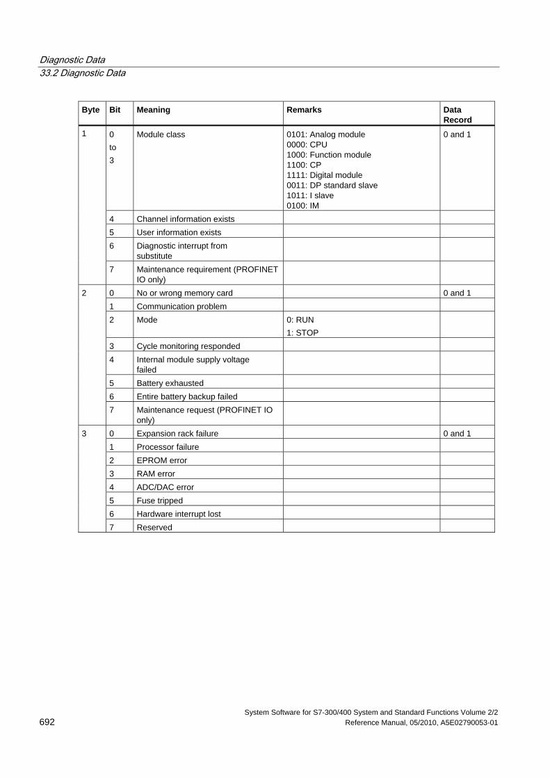
Diagnostic Data 33.2 Diagnostic Data
System Software for S7-300/400 System and Standard Functions Volume 2/2 692 Reference Manual, 05/2010, A5E02790053-01
Byte Bit Meaning Remarks Data Record
0 to 3
Module class 0101: Analog module 0000: CPU 1000: Function module 1100: CP 1111: Digital module 0011: DP standard slave 1011: I slave 0100: IM
0 and 1
4 Channel information exists 5 User information exists 6 Diagnostic interrupt from
substitute
1
7 Maintenance requirement (PROFINET IO only)
0 No or wrong memory card 0 and 1 1 Communication problem 2 Mode 0: RUN
1: STOP
3 Cycle monitoring responded 4 Internal module supply voltage
failed
5 Battery exhausted 6 Entire battery backup failed
2
7 Maintenance request (PROFINET IO only)
0 Expansion rack failure 0 and 1 1 Processor failure 2 EPROM error 3 RAM error 4 ADC/DAC error 5 Fuse tripped 6 Hardware interrupt lost
3
7 Reserved
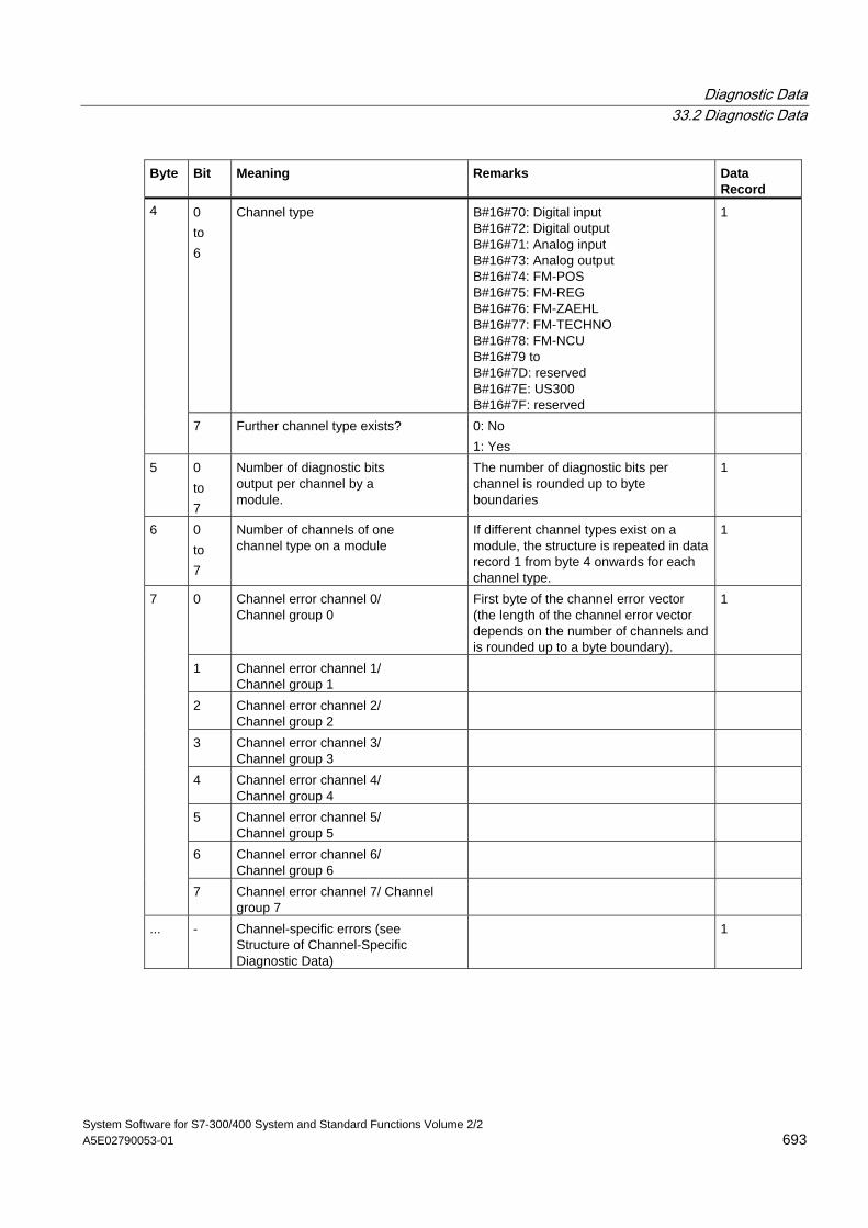
Diagnostic Data 33.2 Diagnostic Data
System Software for S7-300/400 System and Standard Functions Volume 2/2 A5E02790053-01 693
Byte Bit Meaning Remarks Data Record
0 to 6
Channel type B#16#70: Digital input B#16#72: Digital output B#16#71: Analog input B#16#73: Analog output B#16#74: FM-POS B#16#75: FM-REG B#16#76: FM-ZAEHL B#16#77: FM-TECHNO B#16#78: FM-NCU B#16#79 to B#16#7D: reserved B#16#7E: US300 B#16#7F: reserved
1 4
7 Further channel type exists? 0: No 1: Yes
5 0 to 7
Number of diagnostic bits output per channel by a module.
The number of diagnostic bits per channel is rounded up to byte boundaries
1
6 0 to 7
Number of channels of one channel type on a module
If different channel types exist on a module, the structure is repeated in data record 1 from byte 4 onwards for each channel type.
1
0 Channel error channel 0/ Channel group 0
First byte of the channel error vector (the length of the channel error vector depends on the number of channels and is rounded up to a byte boundary).
1
1 Channel error channel 1/ Channel group 1
2 Channel error channel 2/ Channel group 2
3 Channel error channel 3/ Channel group 3
4 Channel error channel 4/ Channel group 4
5 Channel error channel 5/ Channel group 5
6 Channel error channel 6/ Channel group 6
7
7 Channel error channel 7/ Channel group 7
... - Channel-specific errors (see Structure of Channel-Specific Diagnostic Data)
1
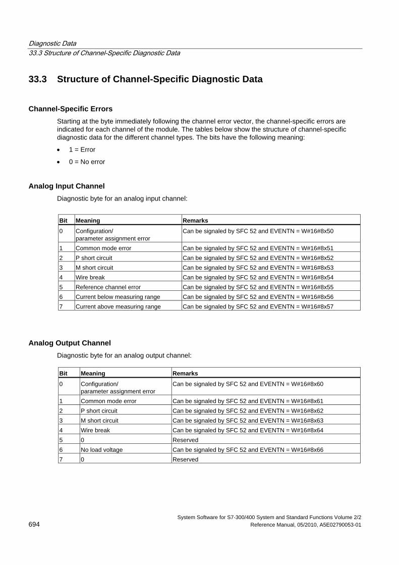
Diagnostic Data 33.3 Structure of Channel-Specific Diagnostic Data
System Software for S7-300/400 System and Standard Functions Volume 2/2 694 Reference Manual, 05/2010, A5E02790053-01
33.3 Structure of Channel-Specific Diagnostic Data
Channel-Specific Errors Starting at the byte immediately following the channel error vector, the channel-specific errors are indicated for each channel of the module. The tables below show the structure of channel-specific diagnostic data for the different channel types. The bits have the following meaning:
• 1 = Error
• 0 = No error
Analog Input Channel Diagnostic byte for an analog input channel:
Bit Meaning Remarks
0 Configuration/ parameter assignment error
Can be signaled by SFC 52 and EVENTN = W#16#8x50
1 Common mode error Can be signaled by SFC 52 and EVENTN = W#16#8x51 2 P short circuit Can be signaled by SFC 52 and EVENTN = W#16#8x52 3 M short circuit Can be signaled by SFC 52 and EVENTN = W#16#8x53 4 Wire break Can be signaled by SFC 52 and EVENTN = W#16#8x54 5 Reference channel error Can be signaled by SFC 52 and EVENTN = W#16#8x55 6 Current below measuring range Can be signaled by SFC 52 and EVENTN = W#16#8x56 7 Current above measuring range Can be signaled by SFC 52 and EVENTN = W#16#8x57
Analog Output Channel Diagnostic byte for an analog output channel: Bit Meaning Remarks
0 Configuration/ parameter assignment error
Can be signaled by SFC 52 and EVENTN = W#16#8x60
1 Common mode error Can be signaled by SFC 52 and EVENTN = W#16#8x61 2 P short circuit Can be signaled by SFC 52 and EVENTN = W#16#8x62 3 M short circuit Can be signaled by SFC 52 and EVENTN = W#16#8x63 4 Wire break Can be signaled by SFC 52 and EVENTN = W#16#8x64 5 0 Reserved 6 No load voltage Can be signaled by SFC 52 and EVENTN = W#16#8x66 7 0 Reserved
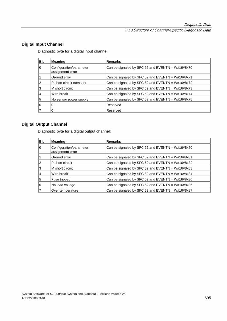
Diagnostic Data 33.3 Structure of Channel-Specific Diagnostic Data
System Software for S7-300/400 System and Standard Functions Volume 2/2 A5E02790053-01 695
Digital Input Channel Diagnostic byte for a digital input channel: Bit Meaning Remarks
0 Configuration/parameter assignment error
Can be signaled by SFC 52 and EVENTN = W#16#8x70
1 Ground error Can be signaled by SFC 52 and EVENTN = W#16#8x71 2 P short circuit (sensor) Can be signaled by SFC 52 and EVENTN = W#16#8x72 3 M short circuit Can be signaled by SFC 52 and EVENTN = W#16#8x73 4 Wire break Can be signaled by SFC 52 and EVENTN = W#16#8x74 5 No sensor power supply Can be signaled by SFC 52 and EVENTN = W#16#8x75 6 0 Reserved 7 0 Reserved
Digital Output Channel Diagnostic byte for a digital output channel: Bit Meaning Remarks
0 Configuration/parameter assignment error
Can be signaled by SFC 52 and EVENTN = W#16#8x80
1 Ground error Can be signaled by SFC 52 and EVENTN = W#16#8x81 2 P short circuit Can be signaled by SFC 52 and EVENTN = W#16#8x82 3 M short circuit Can be signaled by SFC 52 and EVENTN = W#16#8x83 4 Wire break Can be signaled by SFC 52 and EVENTN = W#16#8x84 5 Fuse tripped Can be signaled by SFC 52 and EVENTN = W#16#8x86 6 No load voltage Can be signaled by SFC 52 and EVENTN = W#16#8x86 7 Over temperature Can be signaled by SFC 52 and EVENTN = W#16#8x87
Diagnostic Data 33.3 Structure of Channel-Specific Diagnostic Data
System Software for S7-300/400 System and Standard Functions Volume 2/2 696 Reference Manual, 05/2010, A5E02790053-01
System Software for S7-300/400 System and Standard Functions Volume 2/2 Reference Manual, 05/2010, A5E02790053-01 697
34 System Status Lists (SSL)
34.1 Overview of the System Status Lists (SSL)
This section describes all the partial lists of the system status list that relate to the following:
• CPUs
• Modules whose partial lists are not module-specific (for example, SSL-IDs W#16#00B1, W#16#00B2, W#16#00B3).
Module-specific partial lists, for example, for CPs and FMs are included in the descriptions of the particular modules.
Definition: System Status List The system status list (SSL) describes the current status of a programmable logic controller. The contents of the SSL can only be read using information functions but cannot be modified. The partial lists are virtual lists, in other words, they are only created by the operating system of the CPUs when specifically requested.
You can only read one system status list using SFC 51 "RDSYSST."
Contents The system status lists contain information about the following:
• System data
• Module status data in the CPU
• Diagnostic data on modules
• Diagnostic buffer
System Data System data are fixed or assigned characteristic data of a CPU. They provide information about the following:
• The configuration of the CPU
• The status of the priority classes
• Communication
System Status Lists (SSL) 34.1 Overview of the System Status Lists (SSL)
System Software for S7-300/400 System and Standard Functions Volume 2/2 698 Reference Manual, 05/2010, A5E02790053-01
Module Status Data Module status data describe the current status of the components monitored by system diagnostic functions.
Diagnostic Data on Modules The modules with diagnostic capabilities assigned to a CPU have diagnostic data that are stored directly on the module.
Diagnostic Buffer The diagnostic buffer contains diagnostic entries in the order in which they occur.
System Status Lists (SSL) 34.2 Structure of a Partial SSL List
System Software for S7-300/400 System and Standard Functions Volume 2/2 A5E02790053-01 699
34.2 Structure of a Partial SSL List
Basics You can read partial lists and partial list extracts using SFC 51 "RDSYSST." You specify what you want to read using the parameters SSL_ID and INDEX.
Structure A partial list consists of the following:
• A header and
• The data records.
Header The header of a partial list consists of the following:
• SSL-ID
• Index
• Length of a data record of the partial list in bytes
• Number of data records contained in the partial list.
Index With certain partial lists or partial list extracts an object type ID or an object number must be specified. The index is used for this purpose. If it is not required for the information, its contents are irrelevant.
Data Records A data record in a partial list has a specific length. This depends on the information in the partial list. How the data words in a data record are used also depends on the particular partial list.
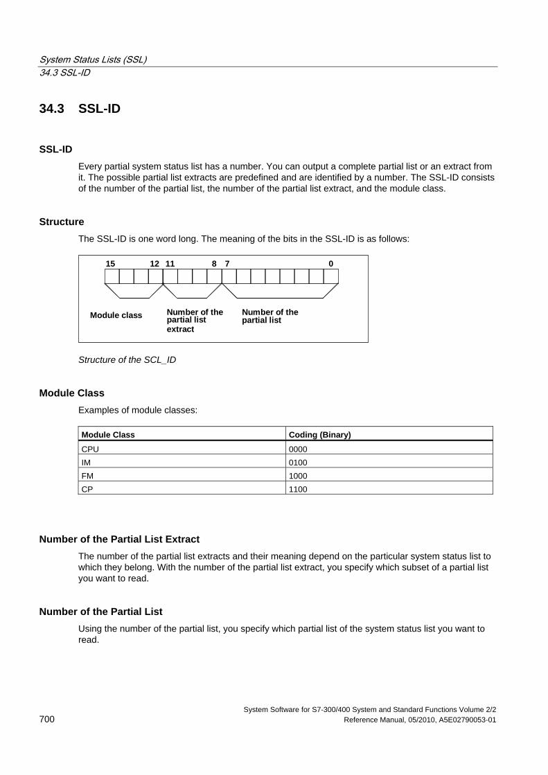
System Status Lists (SSL) 34.3 SSL-ID
System Software for S7-300/400 System and Standard Functions Volume 2/2 700 Reference Manual, 05/2010, A5E02790053-01
34.3 SSL-ID
SSL-ID Every partial system status list has a number. You can output a complete partial list or an extract from it. The possible partial list extracts are predefined and are identified by a number. The SSL-ID consists of the number of the partial list, the number of the partial list extract, and the module class.
Structure The SSL-ID is one word long. The meaning of the bits in the SSL-ID is as follows:
1215 811 7 0
Module class Number of thepartial listextract
Number of thepartial list
Structure of the SCL_ID
Module Class Examples of module classes: Module Class Coding (Binary)
CPU 0000 IM 0100 FM 1000 CP 1100
Number of the Partial List Extract The number of the partial list extracts and their meaning depend on the particular system status list to which they belong. With the number of the partial list extract, you specify which subset of a partial list you want to read.
Number of the Partial List Using the number of the partial list, you specify which partial list of the system status list you want to read.
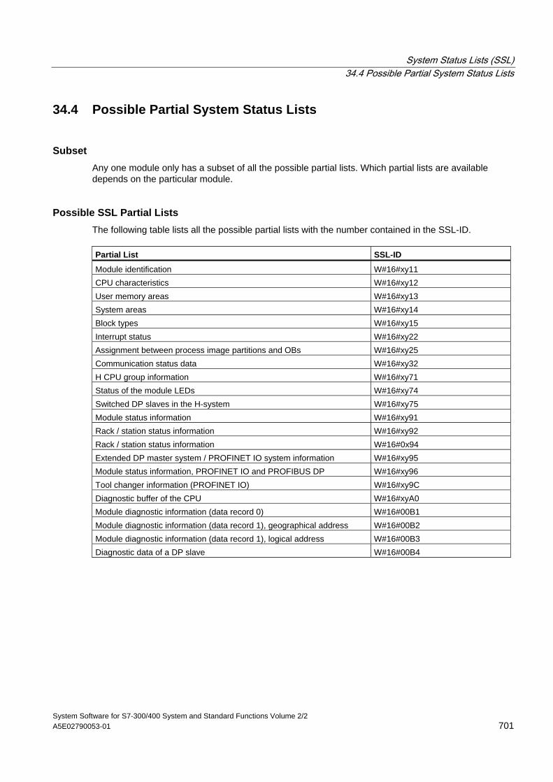
System Status Lists (SSL) 34.4 Possible Partial System Status Lists
System Software for S7-300/400 System and Standard Functions Volume 2/2 A5E02790053-01 701
34.4 Possible Partial System Status Lists
Subset Any one module only has a subset of all the possible partial lists. Which partial lists are available depends on the particular module.
Possible SSL Partial Lists The following table lists all the possible partial lists with the number contained in the SSL-ID. Partial List SSL-ID
Module identification W#16#xy11 CPU characteristics W#16#xy12 User memory areas W#16#xy13 System areas W#16#xy14 Block types W#16#xy15 Interrupt status W#16#xy22 Assignment between process image partitions and OBs W#16#xy25 Communication status data W#16#xy32 H CPU group information W#16#xy71 Status of the module LEDs W#16#xy74 Switched DP slaves in the H-system W#16#xy75 Module status information W#16#xy91 Rack / station status information W#16#xy92 Rack / station status information W#16#0x94 Extended DP master system / PROFINET IO system information W#16#xy95 Module status information, PROFINET IO and PROFIBUS DP W#16#xy96 Tool changer information (PROFINET IO) W#16#xy9C Diagnostic buffer of the CPU W#16#xyA0 Module diagnostic information (data record 0) W#16#00B1 Module diagnostic information (data record 1), geographical address W#16#00B2 Module diagnostic information (data record 1), logical address W#16#00B3 Diagnostic data of a DP slave W#16#00B4
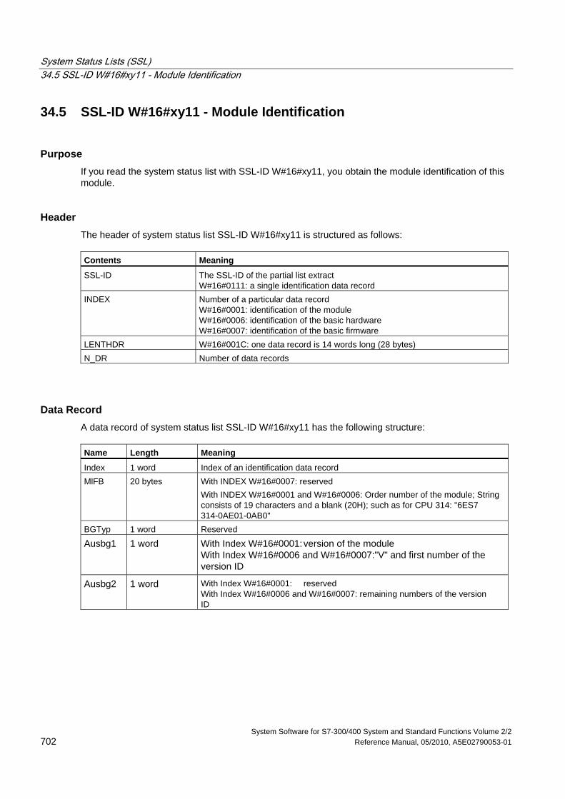
System Status Lists (SSL) 34.5 SSL-ID W#16#xy11 - Module Identification
System Software for S7-300/400 System and Standard Functions Volume 2/2 702 Reference Manual, 05/2010, A5E02790053-01
34.5 SSL-ID W#16#xy11 - Module Identification
Purpose If you read the system status list with SSL-ID W#16#xy11, you obtain the module identification of this module.
Header The header of system status list SSL-ID W#16#xy11 is structured as follows: Contents Meaning
SSL-ID The SSL-ID of the partial list extract W#16#0111: a single identification data record
INDEX Number of a particular data record W#16#0001: identification of the module W#16#0006: identification of the basic hardware W#16#0007: identification of the basic firmware
LENTHDR W#16#001C: one data record is 14 words long (28 bytes) N_DR Number of data records
Data Record A data record of system status list SSL-ID W#16#xy11 has the following structure: Name Length Meaning
Index 1 word Index of an identification data record MlFB 20 bytes With INDEX W#16#0007: reserved
With INDEX W#16#0001 and W#16#0006: Order number of the module; String consists of 19 characters and a blank (20H); such as for CPU 314: "6ES7 314-0AE01-0AB0"
BGTyp 1 word Reserved
Ausbg1 1 word With Index W#16#0001: version of the module With Index W#16#0006 and W#16#0007:"V" and first number of the version ID
Ausbg2 1 word With Index W#16#0001: reserved With Index W#16#0006 and W#16#0007: remaining numbers of the version ID
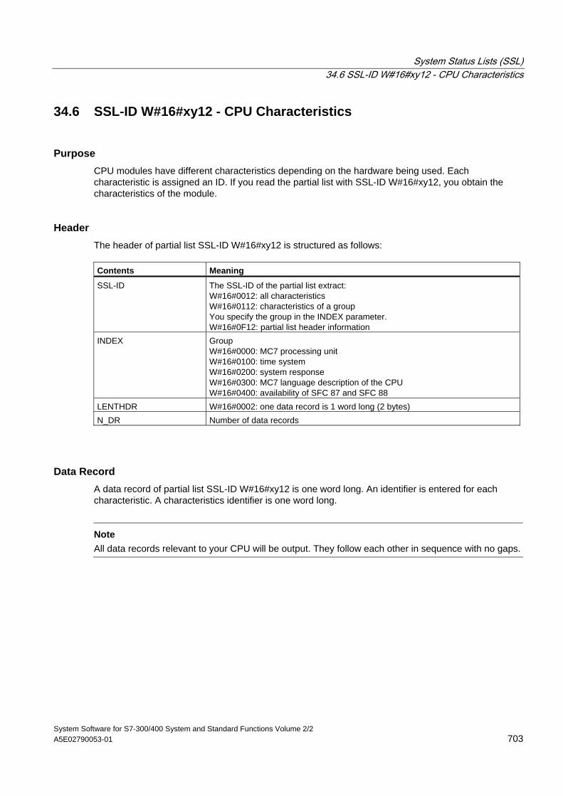
System Status Lists (SSL) 34.6 SSL-ID W#16#xy12 - CPU Characteristics
System Software for S7-300/400 System and Standard Functions Volume 2/2 A5E02790053-01 703
34.6 SSL-ID W#16#xy12 - CPU Characteristics
Purpose CPU modules have different characteristics depending on the hardware being used. Each characteristic is assigned an ID. If you read the partial list with SSL-ID W#16#xy12, you obtain the characteristics of the module.
Header The header of partial list SSL-ID W#16#xy12 is structured as follows: Contents Meaning
SSL-ID The SSL-ID of the partial list extract: W#16#0012: all characteristics W#16#0112: characteristics of a group You specify the group in the INDEX parameter. W#16#0F12: partial list header information
INDEX Group W#16#0000: MC7 processing unit W#16#0100: time system W#16#0200: system response W#16#0300: MC7 language description of the CPU W#16#0400: availability of SFC 87 and SFC 88
LENTHDR W#16#0002: one data record is 1 word long (2 bytes) N_DR Number of data records
Data Record A data record of partial list SSL-ID W#16#xy12 is one word long. An identifier is entered for each characteristic. A characteristics identifier is one word long.
Note
All data records relevant to your CPU will be output. They follow each other in sequence with no gaps.
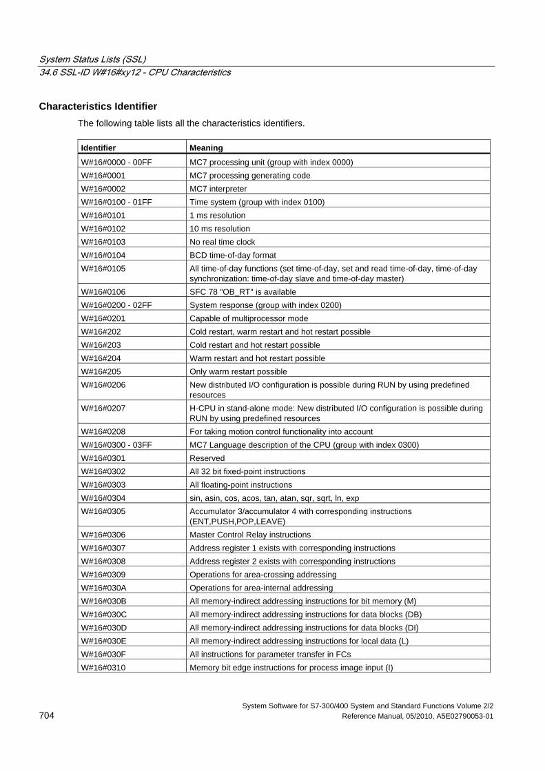
System Status Lists (SSL) 34.6 SSL-ID W#16#xy12 - CPU Characteristics
System Software for S7-300/400 System and Standard Functions Volume 2/2 704 Reference Manual, 05/2010, A5E02790053-01
Characteristics Identifier The following table lists all the characteristics identifiers. Identifier Meaning
W#16#0000 - 00FF MC7 processing unit (group with index 0000) W#16#0001 MC7 processing generating code W#16#0002 MC7 interpreter W#16#0100 - 01FF Time system (group with index 0100) W#16#0101 1 ms resolution W#16#0102 10 ms resolution W#16#0103 No real time clock W#16#0104 BCD time-of-day format W#16#0105 All time-of-day functions (set time-of-day, set and read time-of-day, time-of-day
synchronization: time-of-day slave and time-of-day master) W#16#0106 SFC 78 "OB_RT" is available W#16#0200 - 02FF System response (group with index 0200) W#16#0201 Capable of multiprocessor mode W#16#202 Cold restart, warm restart and hot restart possible W#16#203 Cold restart and hot restart possible W#16#204 Warm restart and hot restart possible W#16#205 Only warm restart possible W#16#0206 New distributed I/O configuration is possible during RUN by using predefined
resources W#16#0207 H-CPU in stand-alone mode: New distributed I/O configuration is possible during
RUN by using predefined resources W#16#0208 For taking motion control functionality into account W#16#0300 - 03FF MC7 Language description of the CPU (group with index 0300) W#16#0301 Reserved W#16#0302 All 32 bit fixed-point instructions W#16#0303 All floating-point instructions W#16#0304 sin, asin, cos, acos, tan, atan, sqr, sqrt, ln, exp W#16#0305 Accumulator 3/accumulator 4 with corresponding instructions
(ENT,PUSH,POP,LEAVE) W#16#0306 Master Control Relay instructions W#16#0307 Address register 1 exists with corresponding instructions W#16#0308 Address register 2 exists with corresponding instructions W#16#0309 Operations for area-crossing addressing W#16#030A Operations for area-internal addressing W#16#030B All memory-indirect addressing instructions for bit memory (M) W#16#030C All memory-indirect addressing instructions for data blocks (DB) W#16#030D All memory-indirect addressing instructions for data blocks (DI) W#16#030E All memory-indirect addressing instructions for local data (L) W#16#030F All instructions for parameter transfer in FCs W#16#0310 Memory bit edge instructions for process image input (I)
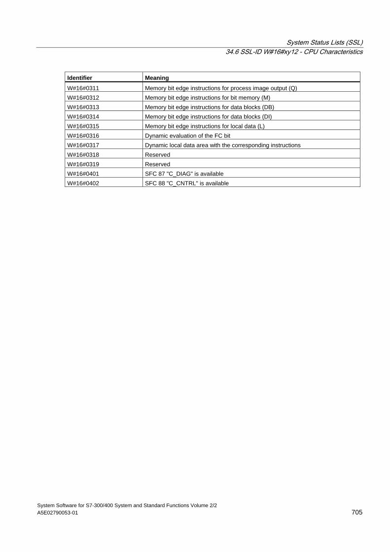
System Status Lists (SSL) 34.6 SSL-ID W#16#xy12 - CPU Characteristics
System Software for S7-300/400 System and Standard Functions Volume 2/2 A5E02790053-01 705
Identifier Meaning
W#16#0311 Memory bit edge instructions for process image output (Q) W#16#0312 Memory bit edge instructions for bit memory (M) W#16#0313 Memory bit edge instructions for data blocks (DB) W#16#0314 Memory bit edge instructions for data blocks (DI) W#16#0315 Memory bit edge instructions for local data (L) W#16#0316 Dynamic evaluation of the FC bit W#16#0317 Dynamic local data area with the corresponding instructions W#16#0318 Reserved W#16#0319 Reserved W#16#0401 SFC 87 "C_DIAG" is available W#16#0402 SFC 88 "C_CNTRL" is available
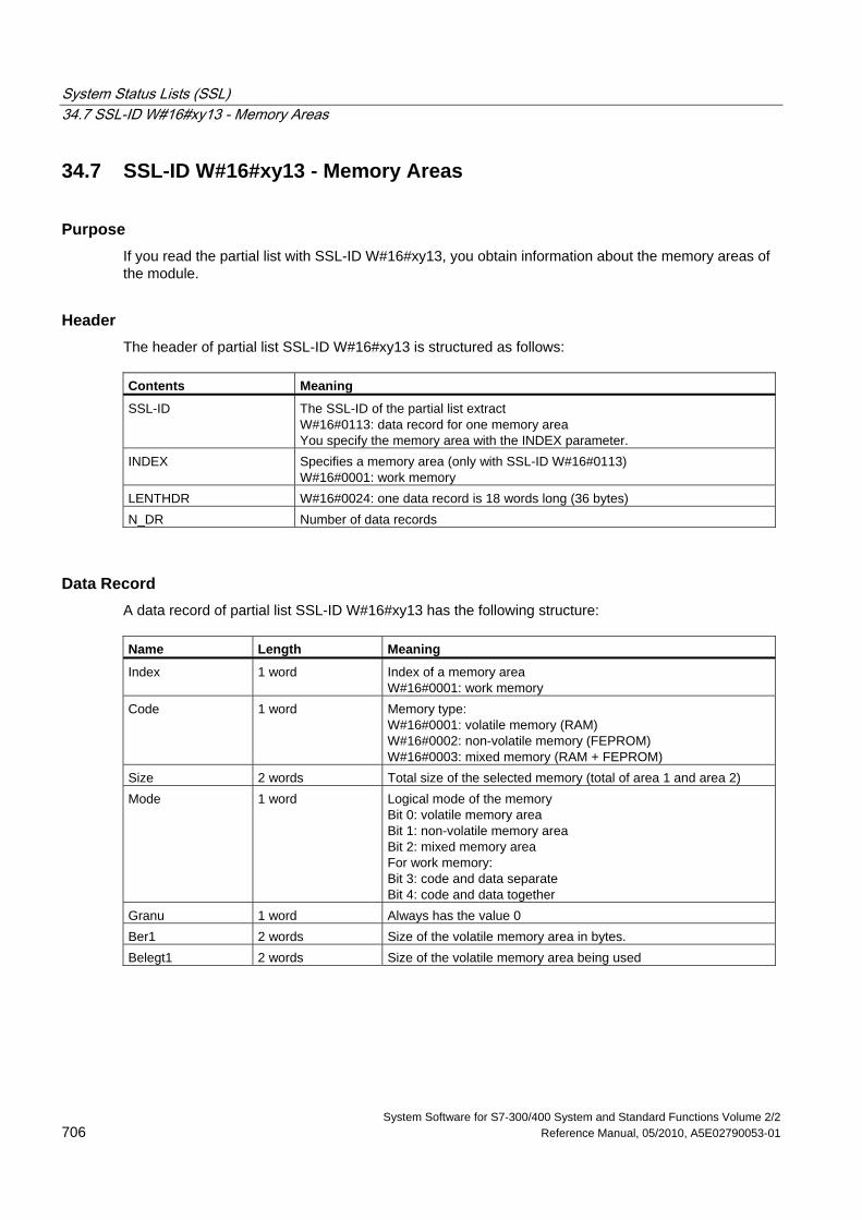
System Status Lists (SSL) 34.7 SSL-ID W#16#xy13 - Memory Areas
System Software for S7-300/400 System and Standard Functions Volume 2/2 706 Reference Manual, 05/2010, A5E02790053-01
34.7 SSL-ID W#16#xy13 - Memory Areas
Purpose If you read the partial list with SSL-ID W#16#xy13, you obtain information about the memory areas of the module.
Header The header of partial list SSL-ID W#16#xy13 is structured as follows: Contents Meaning
SSL-ID The SSL-ID of the partial list extract W#16#0113: data record for one memory area You specify the memory area with the INDEX parameter.
INDEX Specifies a memory area (only with SSL-ID W#16#0113) W#16#0001: work memory
LENTHDR W#16#0024: one data record is 18 words long (36 bytes) N_DR Number of data records
Data Record A data record of partial list SSL-ID W#16#xy13 has the following structure: Name Length Meaning
Index 1 word Index of a memory area W#16#0001: work memory
Code 1 word Memory type: W#16#0001: volatile memory (RAM) W#16#0002: non-volatile memory (FEPROM) W#16#0003: mixed memory (RAM + FEPROM)
Size 2 words Total size of the selected memory (total of area 1 and area 2) Mode 1 word Logical mode of the memory
Bit 0: volatile memory area Bit 1: non-volatile memory area Bit 2: mixed memory area For work memory: Bit 3: code and data separate Bit 4: code and data together
Granu 1 word Always has the value 0 Ber1 2 words Size of the volatile memory area in bytes. Belegt1 2 words Size of the volatile memory area being used
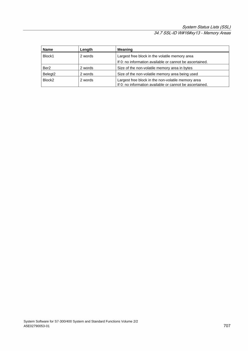
System Status Lists (SSL) 34.7 SSL-ID W#16#xy13 - Memory Areas
System Software for S7-300/400 System and Standard Functions Volume 2/2 A5E02790053-01 707
Name Length Meaning
Block1 2 words Largest free block in the volatile memory area If 0: no information available or cannot be ascertained.
Ber2 2 words Size of the non-volatile memory area in bytes Belegt2 2 words Size of the non-volatile memory area being used Block2 2 words Largest free block in the non-volatile memory area
If 0: no information available or cannot be ascertained.
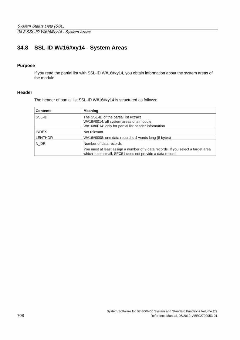
System Status Lists (SSL) 34.8 SSL-ID W#16#xy14 - System Areas
System Software for S7-300/400 System and Standard Functions Volume 2/2 708 Reference Manual, 05/2010, A5E02790053-01
34.8 SSL-ID W#16#xy14 - System Areas
Purpose If you read the partial list with SSL-ID W#16#xy14, you obtain information about the system areas of the module.
Header The header of partial list SSL-ID W#16#xy14 is structured as follows: Contents Meaning
SSL-ID The SSL-ID of the partial list extract W#16#0014: all system areas of a module W#16#0F14: only for partial list header information
INDEX Not relevant LENTHDR W#16#0008: one data record is 4 words long (8 bytes) N_DR Number of data records
You must at least assign a number of 9 data records. If you select a target area which is too small, SFC51 does not provide a data record.
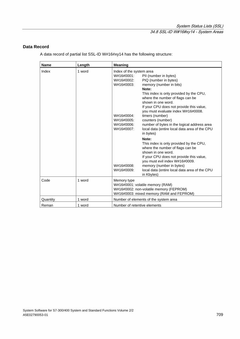
System Status Lists (SSL) 34.8 SSL-ID W#16#xy14 - System Areas
System Software for S7-300/400 System and Standard Functions Volume 2/2 A5E02790053-01 709
Data Record A data record of partial list SSL-ID W#16#xy14 has the following structure: Name Length Meaning
Index 1 word Index of the system area W#16#0001: PII (number in bytes) W#16#0002: PIQ (number in bytes) W#16#0003: memory (number in bits) Note: This index is only provided by the CPU, where the number of flags can be shown in one word. If your CPU does not provide this value, you must evaluate index W#16#0008. W#16#0004: timers (number) W#16#0005: counters (number) W#16#0006: number of bytes in the logical address area W#16#0007: local data (entire local data area of the CPU in bytes) Note: This index is only provided by the CPU, where the number of flags can be shown in one word. If your CPU does not provide this value, you must evil index W#16#0009. W#16#0008: memory (number in bytes) W#16#0009: local data (entire local data area of the CPU in Kbytes)
Code 1 word Memory type W#16#0001: volatile memory (RAM) W#16#0002: non-volatile memory (FEPROM) W#16#0003: mixed memory (RAM and FEPROM)
Quantity 1 word Number of elements of the system area Reman 1 word Number of retentive elements
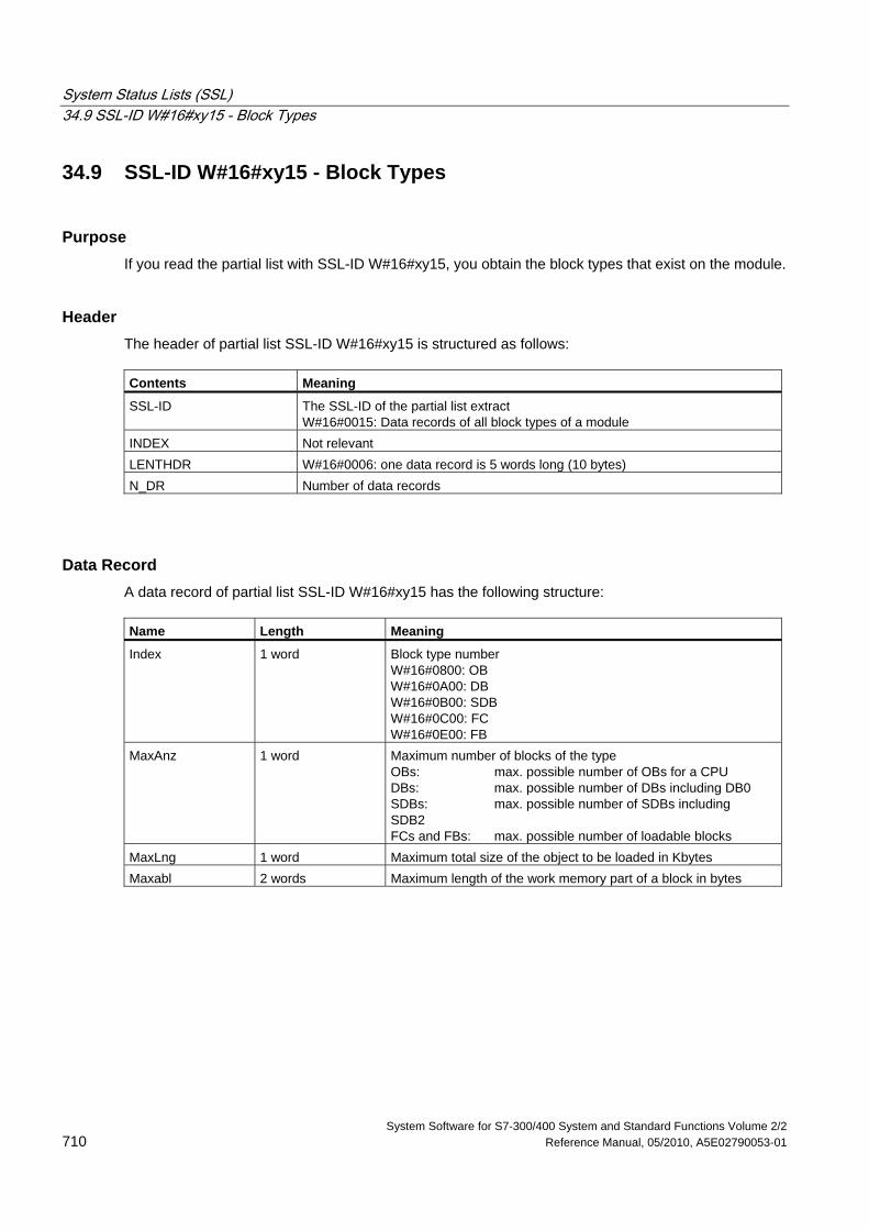
System Status Lists (SSL) 34.9 SSL-ID W#16#xy15 - Block Types
System Software for S7-300/400 System and Standard Functions Volume 2/2 710 Reference Manual, 05/2010, A5E02790053-01
34.9 SSL-ID W#16#xy15 - Block Types
Purpose If you read the partial list with SSL-ID W#16#xy15, you obtain the block types that exist on the module.
Header The header of partial list SSL-ID W#16#xy15 is structured as follows: Contents Meaning
SSL-ID The SSL-ID of the partial list extract W#16#0015: Data records of all block types of a module
INDEX Not relevant LENTHDR W#16#0006: one data record is 5 words long (10 bytes) N_DR Number of data records
Data Record A data record of partial list SSL-ID W#16#xy15 has the following structure: Name Length Meaning
Index 1 word Block type number W#16#0800: OB W#16#0A00: DB W#16#0B00: SDB W#16#0C00: FC W#16#0E00: FB
MaxAnz 1 word Maximum number of blocks of the type OBs: max. possible number of OBs for a CPU DBs: max. possible number of DBs including DB0 SDBs: max. possible number of SDBs including SDB2 FCs and FBs: max. possible number of loadable blocks
MaxLng 1 word Maximum total size of the object to be loaded in Kbytes Maxabl 2 words Maximum length of the work memory part of a block in bytes
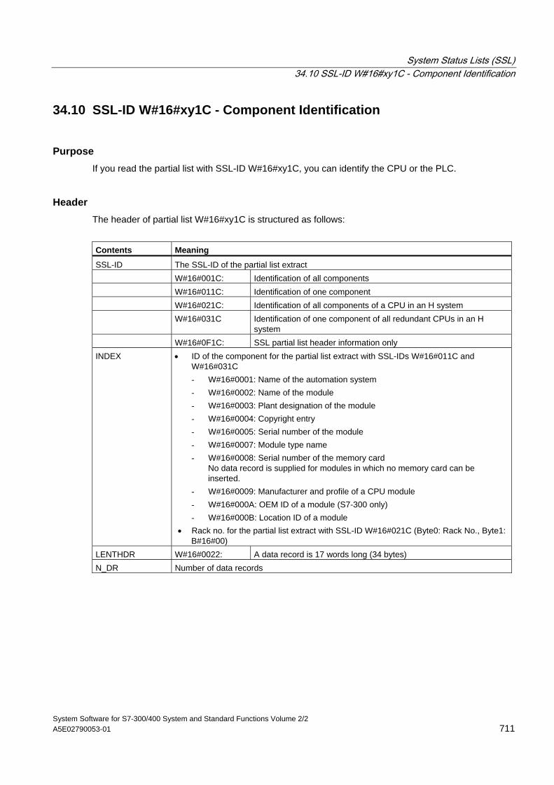
System Status Lists (SSL) 34.10 SSL-ID W#16#xy1C - Component Identification
System Software for S7-300/400 System and Standard Functions Volume 2/2 A5E02790053-01 711
34.10 SSL-ID W#16#xy1C - Component Identification
Purpose If you read the partial list with SSL-ID W#16#xy1C, you can identify the CPU or the PLC.
Header The header of partial list W#16#xy1C is structured as follows:
Contents Meaning
SSL-ID The SSL-ID of the partial list extract W#16#001C: Identification of all components W#16#011C: Identification of one component W#16#021C: Identification of all components of a CPU in an H system W#16#031C Identification of one component of all redundant CPUs in an H
system W#16#0F1C: SSL partial list header information only INDEX • ID of the component for the partial list extract with SSL-IDs W#16#011C and
W#16#031C - W#16#0001: Name of the automation system - W#16#0002: Name of the module - W#16#0003: Plant designation of the module - W#16#0004: Copyright entry - W#16#0005: Serial number of the module - W#16#0007: Module type name - W#16#0008: Serial number of the memory card
No data record is supplied for modules in which no memory card can be inserted.
- W#16#0009: Manufacturer and profile of a CPU module - W#16#000A: OEM ID of a module (S7-300 only) - W#16#000B: Location ID of a module
• Rack no. for the partial list extract with SSL-ID W#16#021C (Byte0: Rack No., Byte1: B#16#00)
LENTHDR W#16#0022: A data record is 17 words long (34 bytes) N_DR Number of data records
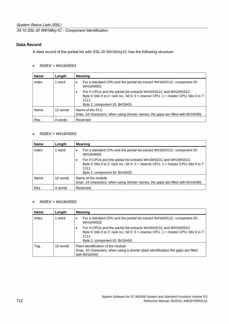
System Status Lists (SSL) 34.10 SSL-ID W#16#xy1C - Component Identification
System Software for S7-300/400 System and Standard Functions Volume 2/2 712 Reference Manual, 05/2010, A5E02790053-01
Data Record A data record of the partial list with SSL-ID W#16#xy1C has the following structure:
• INDEX = W#16#0001
Name Length Meaning
Index 1 word • For a standard CPU and the partial list extract W#16#011C: component ID: W#16#0001
• For H CPUs and the partial list extracts W#16#021C and W#16#031C: Byte 0: bits 0 to 2: rack no.; bit 3: 0 = reserve CPU, 1 = master CPU; bits 4 to 7: 1111 Byte 1: component ID: B#16#01
Name 12 words Name of the PLC (max. 24 characters; when using shorter names, the gaps are filled with B#16#00)
Res 4 words Reserved
• INDEX = W#16#0002
Name Length Meaning
Index 1 word • For a standard CPU and the partial list extract W#16#011C: component ID: W#16#0002
• For H CPUs and the partial list extracts W#16#021C and W#16#031C: Byte 0: bits 0 to 2: rack no.; bit 3: 0 = reserve CPU, 1 = master CPU; bits 4 to 7: 1111 Byte 1: component ID: B#16#02
Name 12 words Name of the module (max. 24 characters; when using shorter names, the gaps are filled with B#16#00)
Res 4 words Reserved
• INDEX = W#16#0003
Name Length Meaning
Index 1 word • For a standard CPU and the partial list extract W#16#011C: component ID: W#16#0003
• For H CPUs and the partial list extracts W#16#021C and W#16#031C: Byte 0: bits 0 to 2: rack no.; bit 3: 0 = reserve CPU, 1 = master CPU; bits 4 to 7: 1111 Byte 1: component ID: B#16#03
Tag 16 words Plant identification of the module (max. 32 characters; when using a shorter plant identification the gaps are filled with B#16#00)
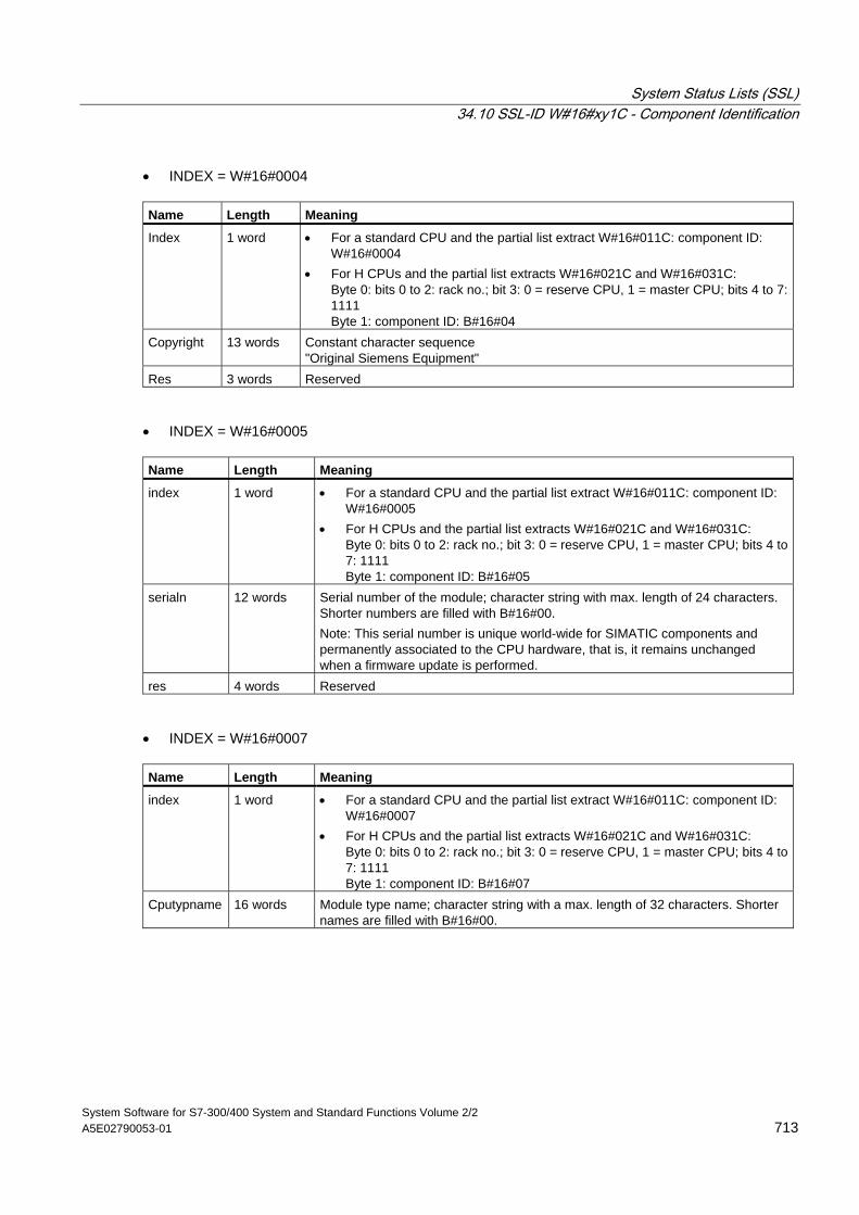
System Status Lists (SSL) 34.10 SSL-ID W#16#xy1C - Component Identification
System Software for S7-300/400 System and Standard Functions Volume 2/2 A5E02790053-01 713
• INDEX = W#16#0004
Name Length Meaning
Index 1 word • For a standard CPU and the partial list extract W#16#011C: component ID: W#16#0004
• For H CPUs and the partial list extracts W#16#021C and W#16#031C: Byte 0: bits 0 to 2: rack no.; bit 3: 0 = reserve CPU, 1 = master CPU; bits 4 to 7: 1111 Byte 1: component ID: B#16#04
Copyright 13 words Constant character sequence "Original Siemens Equipment"
Res 3 words Reserved
• INDEX = W#16#0005
Name Length Meaning
index 1 word • For a standard CPU and the partial list extract W#16#011C: component ID: W#16#0005
• For H CPUs and the partial list extracts W#16#021C and W#16#031C: Byte 0: bits 0 to 2: rack no.; bit 3: 0 = reserve CPU, 1 = master CPU; bits 4 to 7: 1111 Byte 1: component ID: B#16#05
serialn 12 words Serial number of the module; character string with max. length of 24 characters. Shorter numbers are filled with B#16#00. Note: This serial number is unique world-wide for SIMATIC components and permanently associated to the CPU hardware, that is, it remains unchanged when a firmware update is performed.
res 4 words Reserved
• INDEX = W#16#0007
Name Length Meaning
index 1 word • For a standard CPU and the partial list extract W#16#011C: component ID: W#16#0007
• For H CPUs and the partial list extracts W#16#021C and W#16#031C: Byte 0: bits 0 to 2: rack no.; bit 3: 0 = reserve CPU, 1 = master CPU; bits 4 to 7: 1111 Byte 1: component ID: B#16#07
Cputypname 16 words Module type name; character string with a max. length of 32 characters. Shorter names are filled with B#16#00.
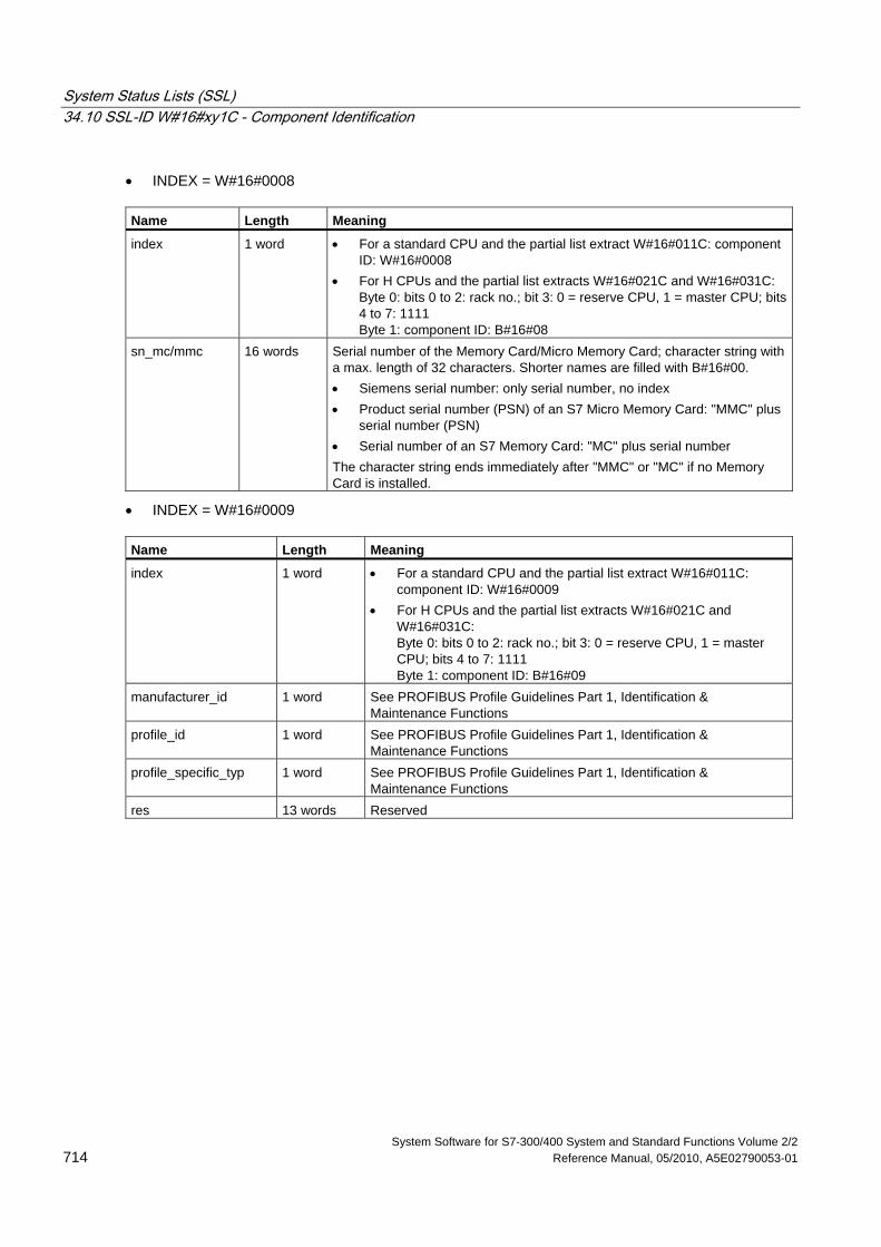
System Status Lists (SSL) 34.10 SSL-ID W#16#xy1C - Component Identification
System Software for S7-300/400 System and Standard Functions Volume 2/2 714 Reference Manual, 05/2010, A5E02790053-01
• INDEX = W#16#0008
Name Length Meaning
index 1 word • For a standard CPU and the partial list extract W#16#011C: component ID: W#16#0008
• For H CPUs and the partial list extracts W#16#021C and W#16#031C: Byte 0: bits 0 to 2: rack no.; bit 3: 0 = reserve CPU, 1 = master CPU; bits 4 to 7: 1111 Byte 1: component ID: B#16#08
sn_mc/mmc 16 words Serial number of the Memory Card/Micro Memory Card; character string with a max. length of 32 characters. Shorter names are filled with B#16#00. • Siemens serial number: only serial number, no index • Product serial number (PSN) of an S7 Micro Memory Card: "MMC" plus
serial number (PSN) • Serial number of an S7 Memory Card: "MC" plus serial number The character string ends immediately after "MMC" or "MC" if no Memory Card is installed.
• INDEX = W#16#0009
Name Length Meaning
index 1 word • For a standard CPU and the partial list extract W#16#011C: component ID: W#16#0009
• For H CPUs and the partial list extracts W#16#021C and W#16#031C: Byte 0: bits 0 to 2: rack no.; bit 3: 0 = reserve CPU, 1 = master CPU; bits 4 to 7: 1111 Byte 1: component ID: B#16#09
manufacturer_id 1 word See PROFIBUS Profile Guidelines Part 1, Identification & Maintenance Functions
profile_id 1 word See PROFIBUS Profile Guidelines Part 1, Identification & Maintenance Functions
profile_specific_typ 1 word See PROFIBUS Profile Guidelines Part 1, Identification & Maintenance Functions
res 13 words Reserved
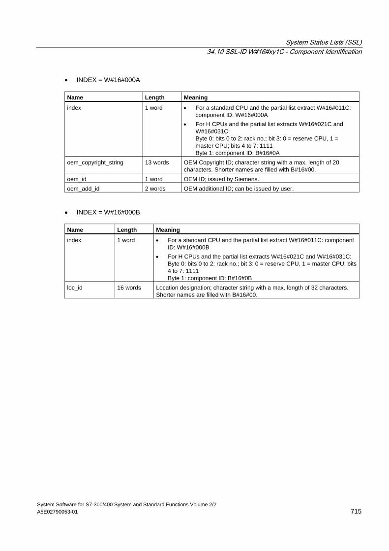
System Status Lists (SSL) 34.10 SSL-ID W#16#xy1C - Component Identification
System Software for S7-300/400 System and Standard Functions Volume 2/2 A5E02790053-01 715
• INDEX = W#16#000A
Name Length Meaning
index 1 word • For a standard CPU and the partial list extract W#16#011C: component ID: W#16#000A
• For H CPUs and the partial list extracts W#16#021C and W#16#031C: Byte 0: bits 0 to 2: rack no.; bit 3: 0 = reserve CPU, 1 = master CPU; bits 4 to 7: 1111 Byte 1: component ID: B#16#0A
oem_copyright_string 13 words OEM Copyright ID; character string with a max. length of 20 characters. Shorter names are filled with B#16#00.
oem_id 1 word OEM ID; issued by Siemens. oem_add_id 2 words OEM additional ID; can be issued by user.
• INDEX = W#16#000B
Name Length Meaning
index 1 word • For a standard CPU and the partial list extract W#16#011C: component ID: W#16#000B
• For H CPUs and the partial list extracts W#16#021C and W#16#031C: Byte 0: bits 0 to 2: rack no.; bit 3: 0 = reserve CPU, 1 = master CPU; bits 4 to 7: 1111 Byte 1: component ID: B#16#0B
loc_id 16 words Location designation; character string with a max. length of 32 characters. Shorter names are filled with B#16#00.
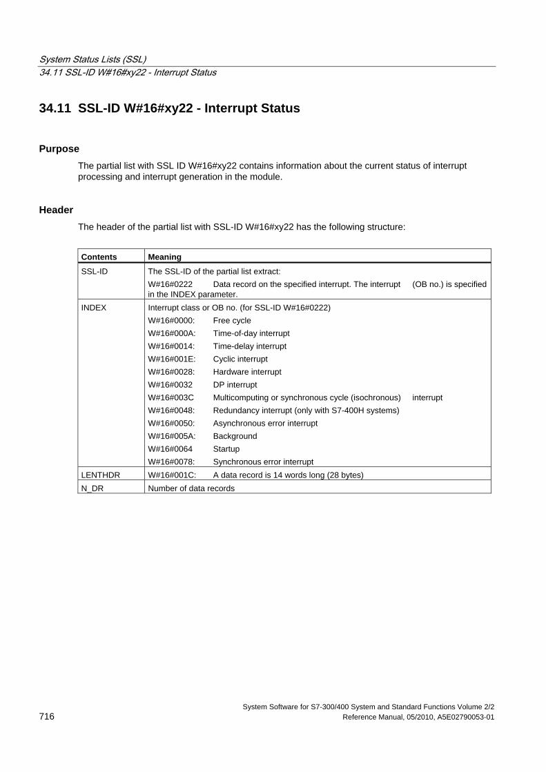
System Status Lists (SSL) 34.11 SSL-ID W#16#xy22 - Interrupt Status
System Software for S7-300/400 System and Standard Functions Volume 2/2 716 Reference Manual, 05/2010, A5E02790053-01
34.11 SSL-ID W#16#xy22 - Interrupt Status
Purpose The partial list with SSL ID W#16#xy22 contains information about the current status of interrupt processing and interrupt generation in the module.
Header The header of the partial list with SSL-ID W#16#xy22 has the following structure:
Contents Meaning
SSL-ID The SSL-ID of the partial list extract: W#16#0222 Data record on the specified interrupt. The interrupt (OB no.) is specified in the INDEX parameter.
INDEX Interrupt class or OB no. (for SSL-ID W#16#0222) W#16#0000: Free cycle W#16#000A: Time-of-day interrupt W#16#0014: Time-delay interrupt W#16#001E: Cyclic interrupt W#16#0028: Hardware interrupt W#16#0032 DP interrupt W#16#003C Multicomputing or synchronous cycle (isochronous) interrupt W#16#0048: Redundancy interrupt (only with S7-400H systems) W#16#0050: Asynchronous error interrupt W#16#005A: Background W#16#0064 Startup W#16#0078: Synchronous error interrupt
LENTHDR W#16#001C: A data record is 14 words long (28 bytes) N_DR Number of data records
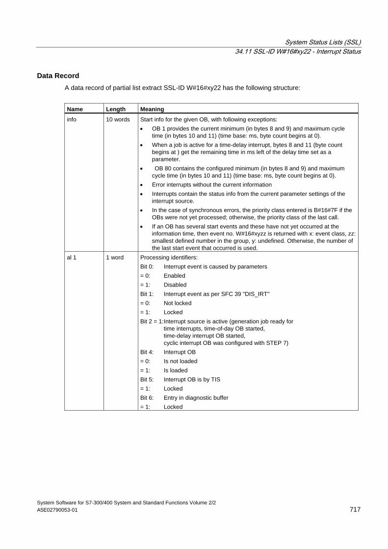
System Status Lists (SSL) 34.11 SSL-ID W#16#xy22 - Interrupt Status
System Software for S7-300/400 System and Standard Functions Volume 2/2 A5E02790053-01 717
Data Record A data record of partial list extract SSL-ID W#16#xy22 has the following structure:
Name Length Meaning
info 10 words Start info for the given OB, with following exceptions: • OB 1 provides the current minimum (in bytes 8 and 9) and maximum cycle
time (in bytes 10 and 11) (time base: ms, byte count begins at 0). • When a job is active for a time-delay interrupt, bytes 8 and 11 (byte count
begins at ) get the remaining time in ms left of the delay time set as a parameter.
• OB 80 contains the configured minimum (in bytes 8 and 9) and maximum cycle time (in bytes 10 and 11) (time base: ms, byte count begins at 0).
• Error interrupts without the current information • Interrupts contain the status info from the current parameter settings of the
interrupt source. • In the case of synchronous errors, the priority class entered is B#16#7F if the
OBs were not yet processed; otherwise, the priority class of the last call. • If an OB has several start events and these have not yet occurred at the
information time, then event no. W#16#xyzz is returned with x: event class, zz: smallest defined number in the group, y: undefined. Otherwise, the number of the last start event that occurred is used.
al 1 1 word Processing identifiers: Bit 0: Interrupt event is caused by parameters = 0: Enabled = 1: Disabled Bit 1: Interrupt event as per SFC 39 "DIS_IRT" = 0: Not locked = 1: Locked Bit 2 = 1: Interrupt source is active (generation job ready for time interrupts, time-of-day OB started, time-delay interrupt OB started, cyclic interrupt OB was configured with STEP 7) Bit 4: Interrupt OB = 0: Is not loaded = 1: Is loaded Bit 5: Interrupt OB is by TIS = 1: Locked Bit 6: Entry in diagnostic buffer = 1: Locked
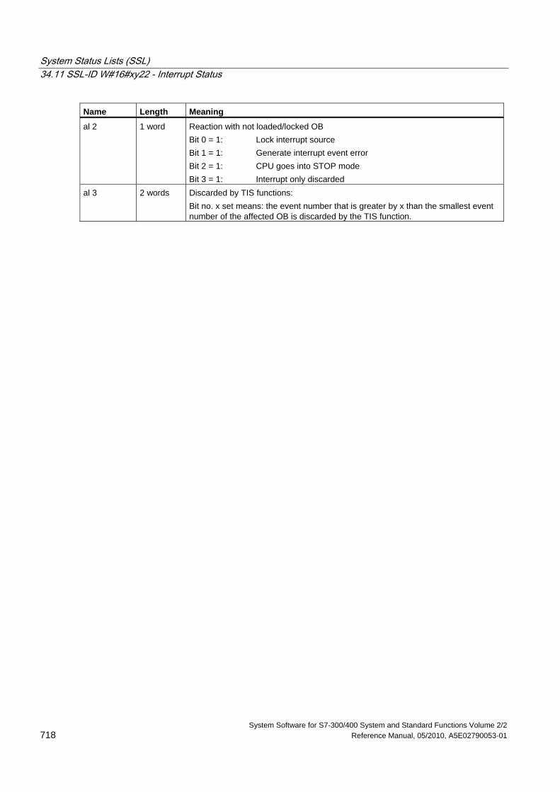
System Status Lists (SSL) 34.11 SSL-ID W#16#xy22 - Interrupt Status
System Software for S7-300/400 System and Standard Functions Volume 2/2 718 Reference Manual, 05/2010, A5E02790053-01
Name Length Meaning
al 2 1 word Reaction with not loaded/locked OB Bit 0 = 1: Lock interrupt source Bit 1 = 1: Generate interrupt event error Bit 2 = 1: CPU goes into STOP mode Bit 3 = 1: Interrupt only discarded
al 3 2 words Discarded by TIS functions: Bit no. x set means: the event number that is greater by x than the smallest event number of the affected OB is discarded by the TIS function.
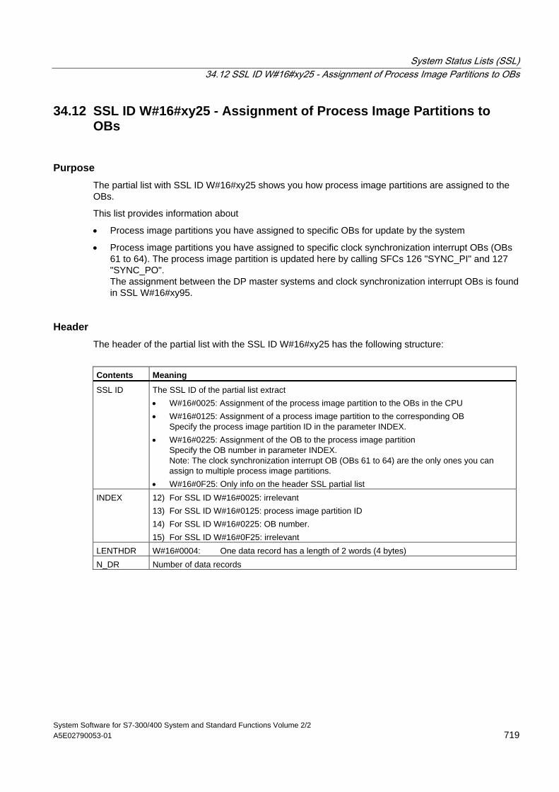
System Status Lists (SSL) 34.12 SSL ID W#16#xy25 - Assignment of Process Image Partitions to OBs
System Software for S7-300/400 System and Standard Functions Volume 2/2 A5E02790053-01 719
34.12 SSL ID W#16#xy25 - Assignment of Process Image Partitions to OBs
Purpose The partial list with SSL ID W#16#xy25 shows you how process image partitions are assigned to the OBs.
This list provides information about
• Process image partitions you have assigned to specific OBs for update by the system
• Process image partitions you have assigned to specific clock synchronization interrupt OBs (OBs 61 to 64). The process image partition is updated here by calling SFCs 126 "SYNC_PI" and 127 "SYNC_PO". The assignment between the DP master systems and clock synchronization interrupt OBs is found in SSL W#16#xy95.
Header The header of the partial list with the SSL ID W#16#xy25 has the following structure:
Contents Meaning
SSL ID The SSL ID of the partial list extract • W#16#0025: Assignment of the process image partition to the OBs in the CPU • W#16#0125: Assignment of a process image partition to the corresponding OB
Specify the process image partition ID in the parameter INDEX. • W#16#0225: Assignment of the OB to the process image partition
Specify the OB number in parameter INDEX. Note: The clock synchronization interrupt OB (OBs 61 to 64) are the only ones you can assign to multiple process image partitions.
• W#16#0F25: Only info on the header SSL partial list INDEX 12) For SSL ID W#16#0025: irrelevant
13) For SSL ID W#16#0125: process image partition ID 14) For SSL ID W#16#0225: OB number. 15) For SSL ID W#16#0F25: irrelevant
LENTHDR W#16#0004: One data record has a length of 2 words (4 bytes) N_DR Number of data records
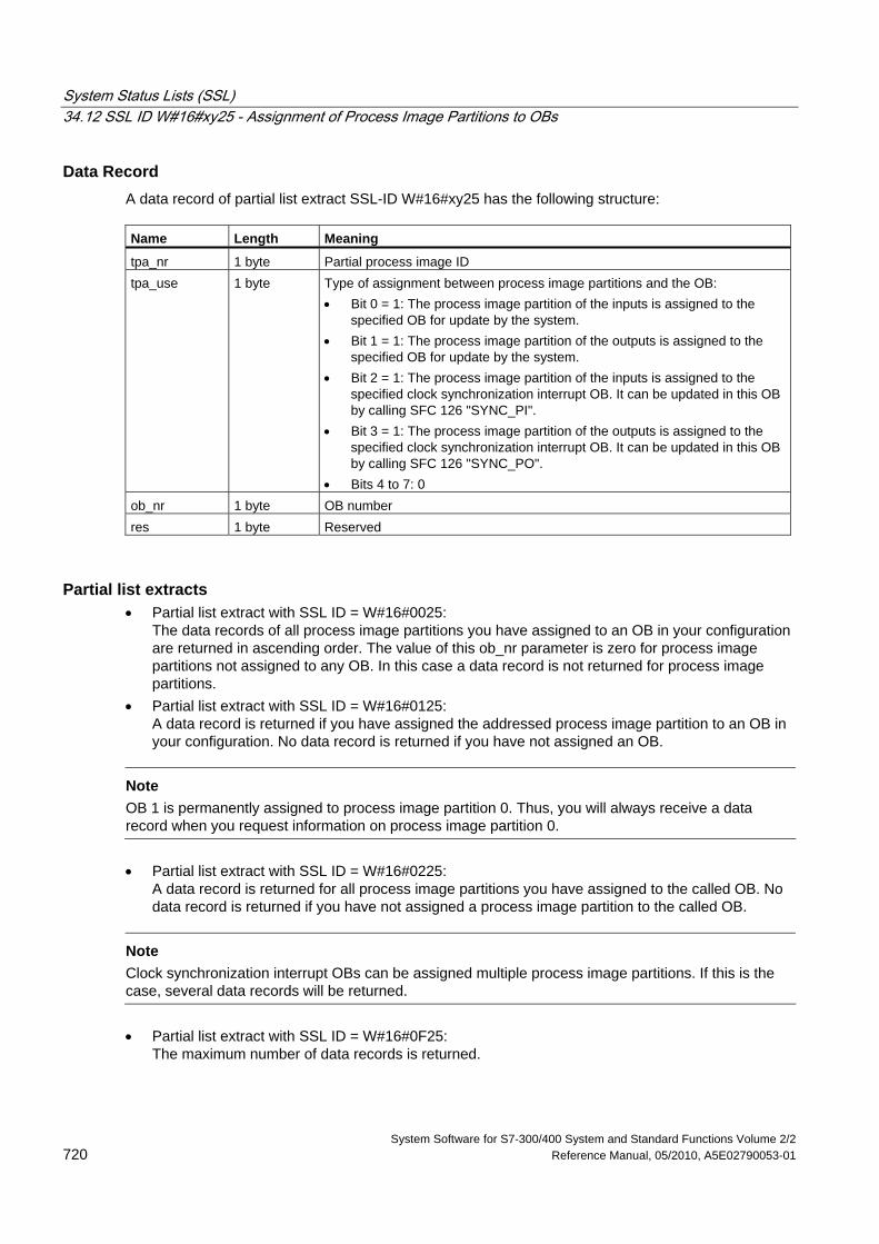
System Status Lists (SSL) 34.12 SSL ID W#16#xy25 - Assignment of Process Image Partitions to OBs
System Software for S7-300/400 System and Standard Functions Volume 2/2 720 Reference Manual, 05/2010, A5E02790053-01
Data Record A data record of partial list extract SSL-ID W#16#xy25 has the following structure: Name Length Meaning
tpa_nr 1 byte Partial process image ID tpa_use 1 byte Type of assignment between process image partitions and the OB:
• Bit 0 = 1: The process image partition of the inputs is assigned to the specified OB for update by the system.
• Bit 1 = 1: The process image partition of the outputs is assigned to the specified OB for update by the system.
• Bit 2 = 1: The process image partition of the inputs is assigned to the specified clock synchronization interrupt OB. It can be updated in this OB by calling SFC 126 "SYNC_PI".
• Bit 3 = 1: The process image partition of the outputs is assigned to the specified clock synchronization interrupt OB. It can be updated in this OB by calling SFC 126 "SYNC_PO".
• Bits 4 to 7: 0 ob_nr 1 byte OB number res 1 byte Reserved
Partial list extracts • Partial list extract with SSL ID = W#16#0025:
The data records of all process image partitions you have assigned to an OB in your configuration are returned in ascending order. The value of this ob_nr parameter is zero for process image partitions not assigned to any OB. In this case a data record is not returned for process image partitions.
• Partial list extract with SSL ID = W#16#0125: A data record is returned if you have assigned the addressed process image partition to an OB in your configuration. No data record is returned if you have not assigned an OB.
Note OB 1 is permanently assigned to process image partition 0. Thus, you will always receive a data record when you request information on process image partition 0. • Partial list extract with SSL ID = W#16#0225:
A data record is returned for all process image partitions you have assigned to the called OB. No data record is returned if you have not assigned a process image partition to the called OB.
Note Clock synchronization interrupt OBs can be assigned multiple process image partitions. If this is the case, several data records will be returned. • Partial list extract with SSL ID = W#16#0F25:
The maximum number of data records is returned.
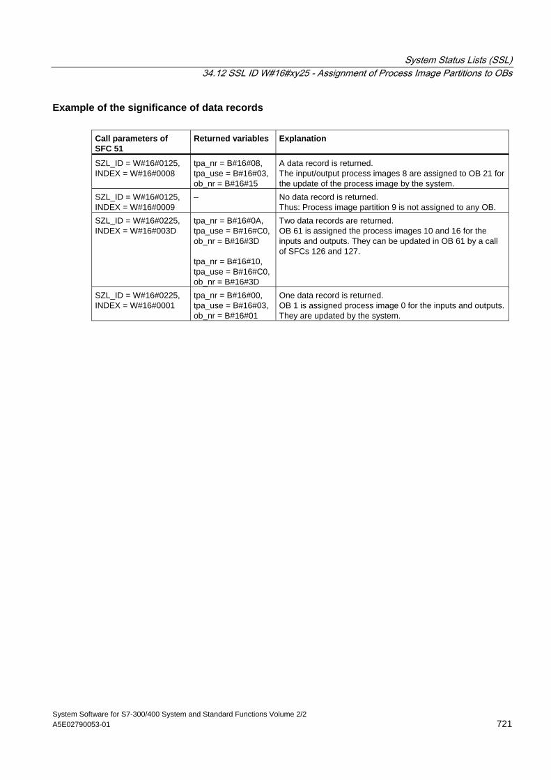
System Status Lists (SSL) 34.12 SSL ID W#16#xy25 - Assignment of Process Image Partitions to OBs
System Software for S7-300/400 System and Standard Functions Volume 2/2 A5E02790053-01 721
Example of the significance of data records Call parameters of SFC 51
Returned variables Explanation
SZL_ID = W#16#0125, INDEX = W#16#0008
tpa_nr = B#16#08, tpa_use = B#16#03, ob_nr = B#16#15
A data record is returned. The input/output process images 8 are assigned to OB 21 for the update of the process image by the system.
SZL_ID = W#16#0125, INDEX = W#16#0009
– No data record is returned. Thus: Process image partition 9 is not assigned to any OB.
SZL_ID = W#16#0225, INDEX = W#16#003D
tpa_nr = B#16#0A, tpa_use = B#16#C0, ob_nr = B#16#3D tpa_nr = B#16#10, tpa_use = B#16#C0, ob_nr = B#16#3D
Two data records are returned. OB 61 is assigned the process images 10 and 16 for the inputs and outputs. They can be updated in OB 61 by a call of SFCs 126 and 127.
SZL_ID = W#16#0225, INDEX = W#16#0001
tpa_nr = B#16#00, tpa_use = B#16#03, ob_nr = B#16#01
One data record is returned. OB 1 is assigned process image 0 for the inputs and outputs. They are updated by the system.
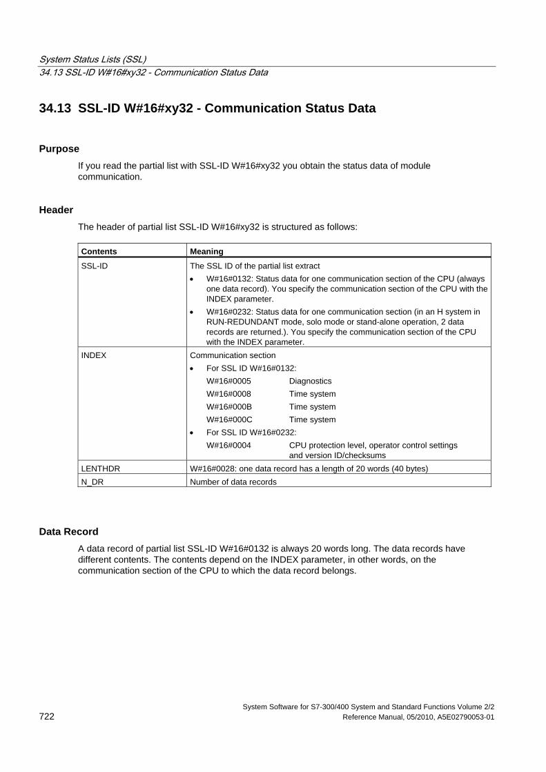
System Status Lists (SSL) 34.13 SSL-ID W#16#xy32 - Communication Status Data
System Software for S7-300/400 System and Standard Functions Volume 2/2 722 Reference Manual, 05/2010, A5E02790053-01
34.13 SSL-ID W#16#xy32 - Communication Status Data
Purpose If you read the partial list with SSL-ID W#16#xy32 you obtain the status data of module communication.
Header The header of partial list SSL-ID W#16#xy32 is structured as follows: Contents Meaning
SSL-ID The SSL ID of the partial list extract • W#16#0132: Status data for one communication section of the CPU (always
one data record). You specify the communication section of the CPU with the INDEX parameter.
• W#16#0232: Status data for one communication section (in an H system in RUN-REDUNDANT mode, solo mode or stand-alone operation, 2 data records are returned.). You specify the communication section of the CPU with the INDEX parameter.
INDEX Communication section • For SSL ID W#16#0132: W#16#0005 Diagnostics W#16#0008 Time system W#16#000B Time system W#16#000C Time system • For SSL ID W#16#0232: W#16#0004 CPU protection level, operator control settings
and version ID/checksums LENTHDR W#16#0028: one data record has a length of 20 words (40 bytes) N_DR Number of data records
Data Record A data record of partial list SSL-ID W#16#0132 is always 20 words long. The data records have different contents. The contents depend on the INDEX parameter, in other words, on the communication section of the CPU to which the data record belongs.
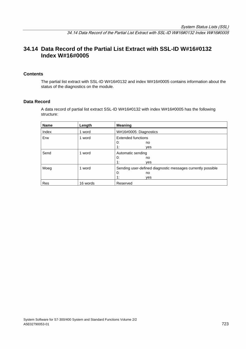
System Status Lists (SSL) 34.14 Data Record of the Partial List Extract with SSL-ID W#16#0132 Index W#16#0005
System Software for S7-300/400 System and Standard Functions Volume 2/2 A5E02790053-01 723
34.14 Data Record of the Partial List Extract with SSL-ID W#16#0132 Index W#16#0005
Contents The partial list extract with SSL-ID W#16#0132 and index W#16#0005 contains information about the status of the diagnostics on the module.
Data Record A data record of partial list extract SSL-ID W#16#0132 with index W#16#0005 has the following structure: Name Length Meaning
Index 1 word W#16#0005: Diagnostics Erw 1 word Extended functions
0: no 1: yes
Send 1 word Automatic sending 0: no 1: yes
Moeg 1 word Sending user-defined diagnostic messages currently possible 0: no 1: yes
Res 16 words Reserved
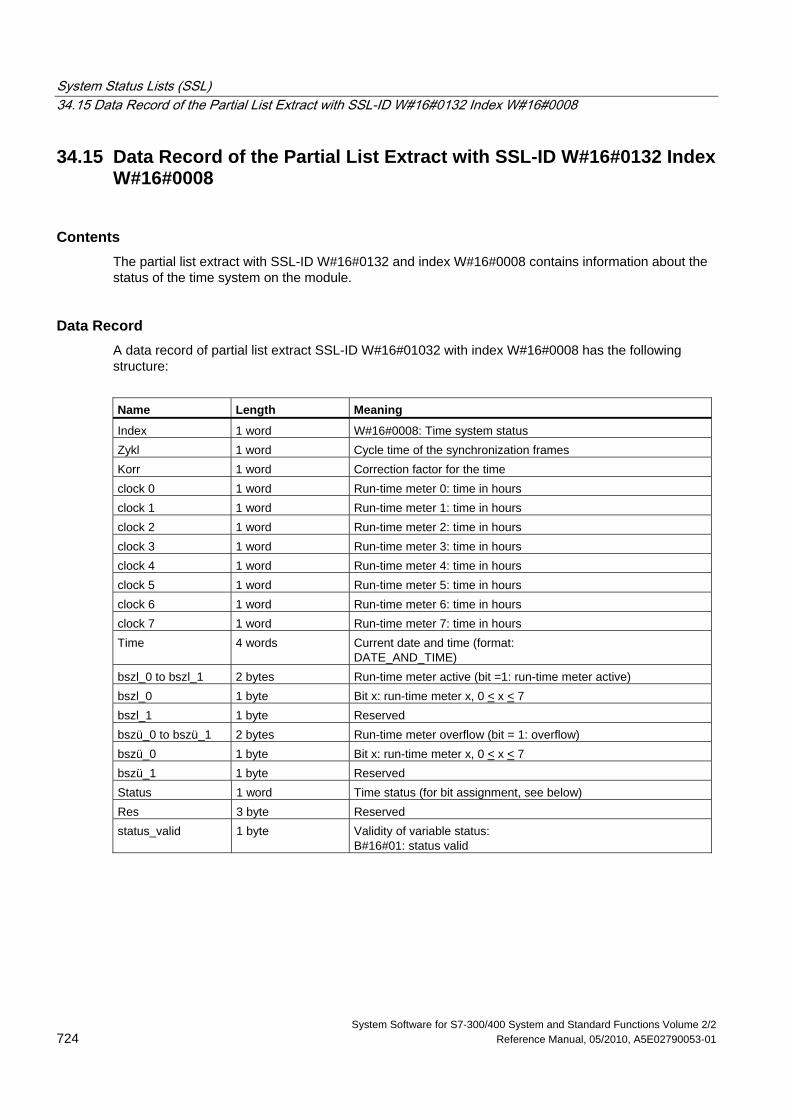
System Status Lists (SSL) 34.15 Data Record of the Partial List Extract with SSL-ID W#16#0132 Index W#16#0008
System Software for S7-300/400 System and Standard Functions Volume 2/2 724 Reference Manual, 05/2010, A5E02790053-01
34.15 Data Record of the Partial List Extract with SSL-ID W#16#0132 Index W#16#0008
Contents The partial list extract with SSL-ID W#16#0132 and index W#16#0008 contains information about the status of the time system on the module.
Data Record A data record of partial list extract SSL-ID W#16#01032 with index W#16#0008 has the following structure:
Name Length Meaning
Index 1 word W#16#0008: Time system status Zykl 1 word Cycle time of the synchronization frames Korr 1 word Correction factor for the time clock 0 1 word Run-time meter 0: time in hours clock 1 1 word Run-time meter 1: time in hours clock 2 1 word Run-time meter 2: time in hours clock 3 1 word Run-time meter 3: time in hours clock 4 1 word Run-time meter 4: time in hours clock 5 1 word Run-time meter 5: time in hours clock 6 1 word Run-time meter 6: time in hours clock 7 1 word Run-time meter 7: time in hours Time 4 words Current date and time (format:
DATE_AND_TIME) bszl_0 to bszl_1 2 bytes Run-time meter active (bit =1: run-time meter active) bszl_0 1 byte Bit x: run-time meter x, 0 < x < 7 bszl_1 1 byte Reserved bszü_0 to bszü_1 2 bytes Run-time meter overflow (bit = 1: overflow) bszü_0 1 byte Bit x: run-time meter x, 0 < x < 7 bszü_1 1 byte Reserved Status 1 word Time status (for bit assignment, see below) Res 3 byte Reserved status_valid 1 byte Validity of variable status:
B#16#01: status valid
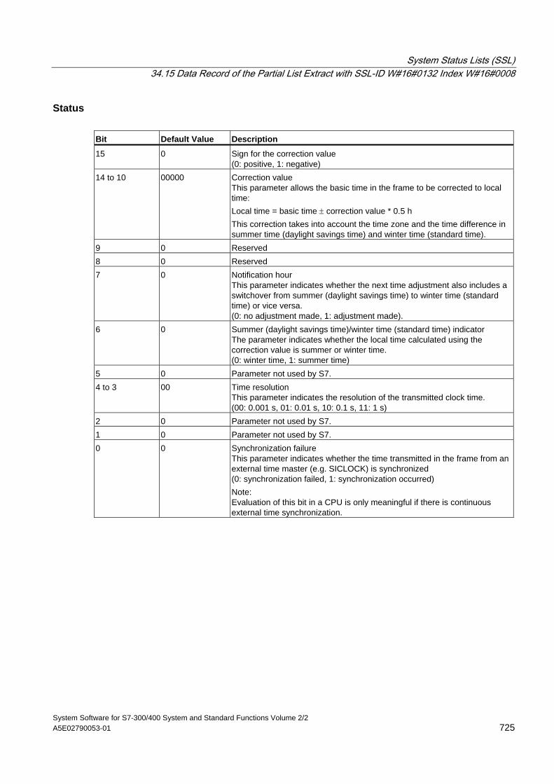
System Status Lists (SSL) 34.15 Data Record of the Partial List Extract with SSL-ID W#16#0132 Index W#16#0008
System Software for S7-300/400 System and Standard Functions Volume 2/2 A5E02790053-01 725
Status Bit Default Value Description
15 0 Sign for the correction value (0: positive, 1: negative)
14 to 10 00000 Correction value This parameter allows the basic time in the frame to be corrected to local time: Local time = basic time ± correction value * 0.5 h This correction takes into account the time zone and the time difference in summer time (daylight savings time) and winter time (standard time).
9 0 Reserved 8 0 Reserved 7 0 Notification hour
This parameter indicates whether the next time adjustment also includes a switchover from summer (daylight savings time) to winter time (standard time) or vice versa. (0: no adjustment made, 1: adjustment made).
6 0 Summer (daylight savings time)/winter time (standard time) indicator The parameter indicates whether the local time calculated using the correction value is summer or winter time. (0: winter time, 1: summer time)
5 0 Parameter not used by S7. 4 to 3 00 Time resolution
This parameter indicates the resolution of the transmitted clock time. (00: 0.001 s, 01: 0.01 s, 10: 0.1 s, 11: 1 s)
2 0 Parameter not used by S7. 1 0 Parameter not used by S7. 0 0 Synchronization failure
This parameter indicates whether the time transmitted in the frame from an external time master (e.g. SICLOCK) is synchronized (0: synchronization failed, 1: synchronization occurred) Note: Evaluation of this bit in a CPU is only meaningful if there is continuous external time synchronization.
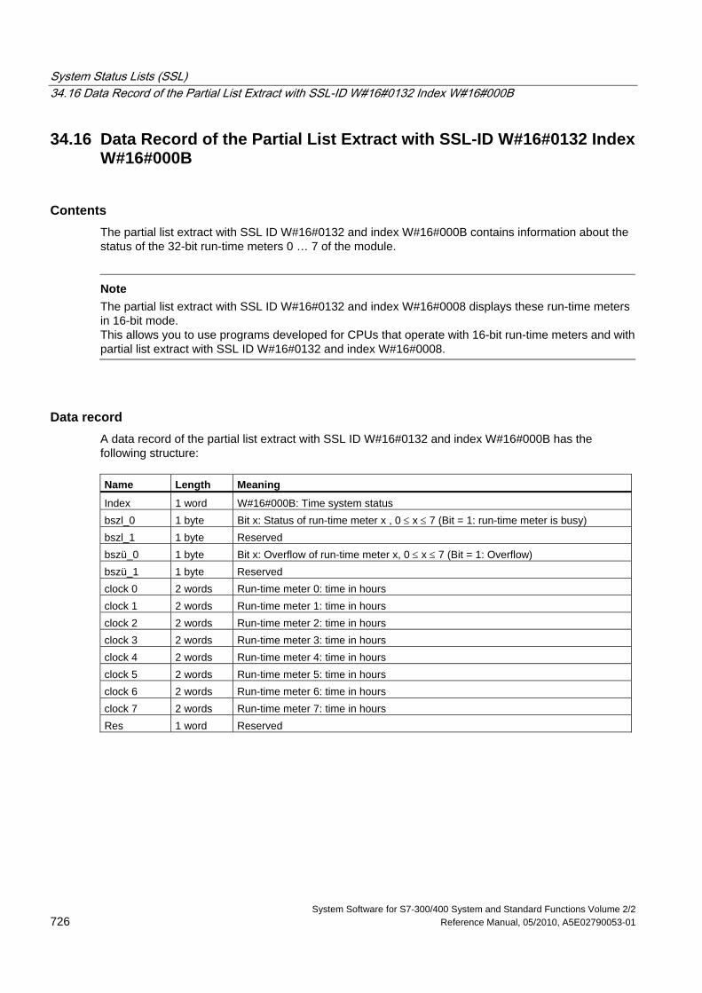
System Status Lists (SSL) 34.16 Data Record of the Partial List Extract with SSL-ID W#16#0132 Index W#16#000B
System Software for S7-300/400 System and Standard Functions Volume 2/2 726 Reference Manual, 05/2010, A5E02790053-01
34.16 Data Record of the Partial List Extract with SSL-ID W#16#0132 Index W#16#000B
Contents The partial list extract with SSL ID W#16#0132 and index W#16#000B contains information about the status of the 32-bit run-time meters 0 … 7 of the module.
Note
The partial list extract with SSL ID W#16#0132 and index W#16#0008 displays these run-time meters in 16-bit mode. This allows you to use programs developed for CPUs that operate with 16-bit run-time meters and with partial list extract with SSL ID W#16#0132 and index W#16#0008.
Data record A data record of the partial list extract with SSL ID W#16#0132 and index W#16#000B has the following structure: Name Length Meaning
Index 1 word W#16#000B: Time system status bszl_0 1 byte Bit x: Status of run-time meter x , 0 ≤ x ≤ 7 (Bit = 1: run-time meter is busy) bszl_1 1 byte Reserved bszü_0 1 byte Bit x: Overflow of run-time meter x, 0 ≤ x ≤ 7 (Bit = 1: Overflow) bszü_1 1 byte Reserved clock 0 2 words Run-time meter 0: time in hours clock 1 2 words Run-time meter 1: time in hours clock 2 2 words Run-time meter 2: time in hours clock 3 2 words Run-time meter 3: time in hours clock 4 2 words Run-time meter 4: time in hours clock 5 2 words Run-time meter 5: time in hours clock 6 2 words Run-time meter 6: time in hours clock 7 2 words Run-time meter 7: time in hours Res 1 word Reserved
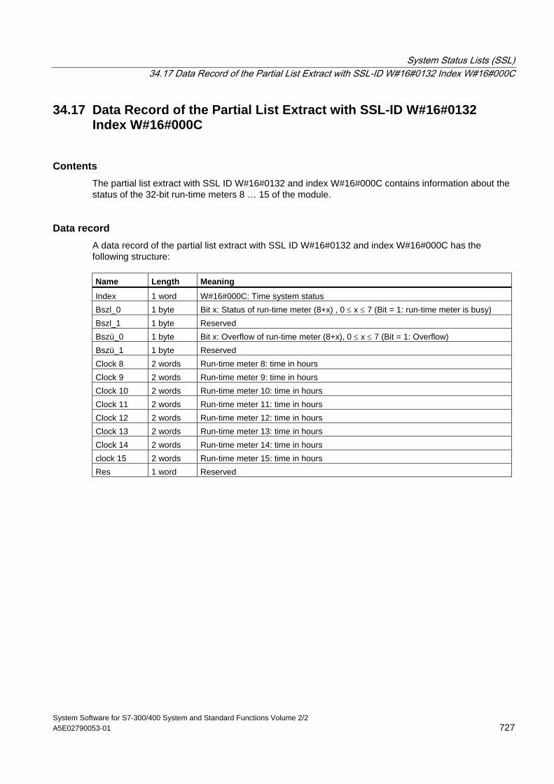
System Status Lists (SSL) 34.17 Data Record of the Partial List Extract with SSL-ID W#16#0132 Index W#16#000C
System Software for S7-300/400 System and Standard Functions Volume 2/2 A5E02790053-01 727
34.17 Data Record of the Partial List Extract with SSL-ID W#16#0132 Index W#16#000C
Contents The partial list extract with SSL ID W#16#0132 and index W#16#000C contains information about the status of the 32-bit run-time meters 8 … 15 of the module.
Data record A data record of the partial list extract with SSL ID W#16#0132 and index W#16#000C has the following structure: Name Length Meaning
Index 1 word W#16#000C: Time system status Bszl_0 1 byte Bit x: Status of run-time meter (8+x) , 0 ≤ x ≤ 7 (Bit = 1: run-time meter is busy) Bszl_1 1 byte Reserved Bszü_0 1 byte Bit x: Overflow of run-time meter (8+x), 0 ≤ x ≤ 7 (Bit = 1: Overflow) Bszü_1 1 byte Reserved Clock 8 2 words Run-time meter 8: time in hours Clock 9 2 words Run-time meter 9: time in hours Clock 10 2 words Run-time meter 10: time in hours Clock 11 2 words Run-time meter 11: time in hours Clock 12 2 words Run-time meter 12: time in hours Clock 13 2 words Run-time meter 13: time in hours Clock 14 2 words Run-time meter 14: time in hours clock 15 2 words Run-time meter 15: time in hours Res 1 word Reserved
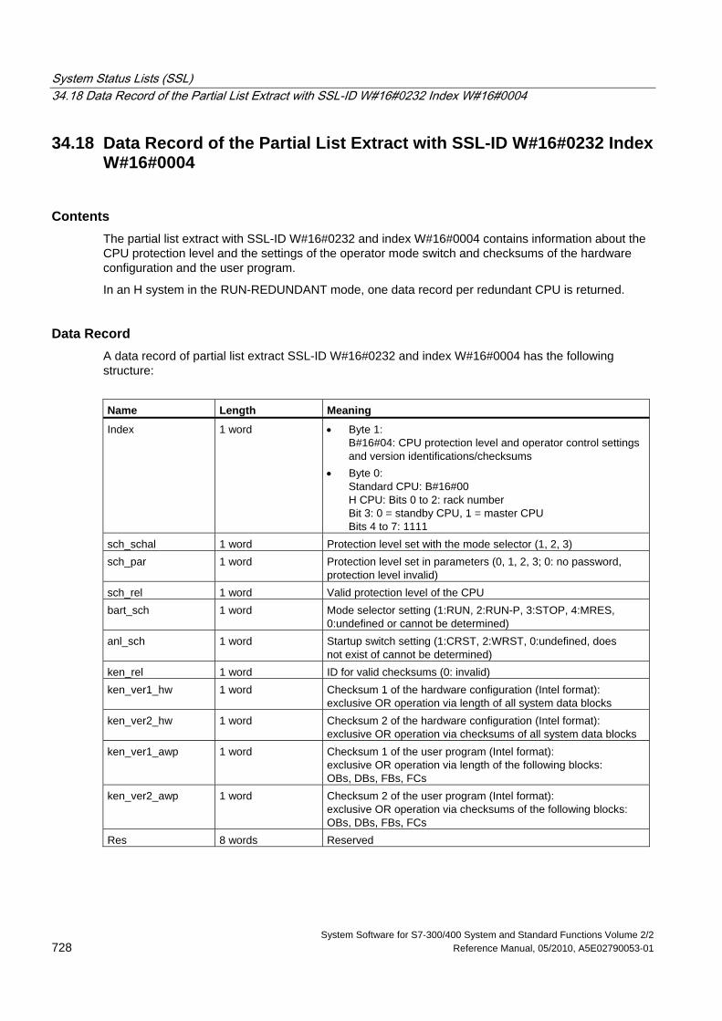
System Status Lists (SSL) 34.18 Data Record of the Partial List Extract with SSL-ID W#16#0232 Index W#16#0004
System Software for S7-300/400 System and Standard Functions Volume 2/2 728 Reference Manual, 05/2010, A5E02790053-01
34.18 Data Record of the Partial List Extract with SSL-ID W#16#0232 Index W#16#0004
Contents The partial list extract with SSL-ID W#16#0232 and index W#16#0004 contains information about the CPU protection level and the settings of the operator mode switch and checksums of the hardware configuration and the user program.
In an H system in the RUN-REDUNDANT mode, one data record per redundant CPU is returned.
Data Record A data record of partial list extract SSL-ID W#16#0232 and index W#16#0004 has the following structure:
Name Length Meaning
Index 1 word • Byte 1: B#16#04: CPU protection level and operator control settings and version identifications/checksums
• Byte 0: Standard CPU: B#16#00 H CPU: Bits 0 to 2: rack number Bit 3: 0 = standby CPU, 1 = master CPU Bits 4 to 7: 1111
sch_schal 1 word Protection level set with the mode selector (1, 2, 3) sch_par 1 word Protection level set in parameters (0, 1, 2, 3; 0: no password,
protection level invalid) sch_rel 1 word Valid protection level of the CPU bart_sch 1 word Mode selector setting (1:RUN, 2:RUN-P, 3:STOP, 4:MRES,
0:undefined or cannot be determined) anl_sch 1 word Startup switch setting (1:CRST, 2:WRST, 0:undefined, does
not exist of cannot be determined) ken_rel 1 word ID for valid checksums (0: invalid) ken_ver1_hw 1 word Checksum 1 of the hardware configuration (Intel format):
exclusive OR operation via length of all system data blocks ken_ver2_hw 1 word Checksum 2 of the hardware configuration (Intel format):
exclusive OR operation via checksums of all system data blocks ken_ver1_awp 1 word Checksum 1 of the user program (Intel format):
exclusive OR operation via length of the following blocks: OBs, DBs, FBs, FCs
ken_ver2_awp 1 word Checksum 2 of the user program (Intel format): exclusive OR operation via checksums of the following blocks: OBs, DBs, FBs, FCs
Res 8 words Reserved
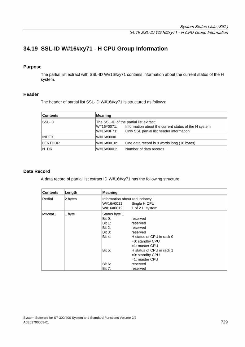
System Status Lists (SSL) 34.19 SSL-ID W#16#xy71 - H CPU Group Information
System Software for S7-300/400 System and Standard Functions Volume 2/2 A5E02790053-01 729
34.19 SSL-ID W#16#xy71 - H CPU Group Information
Purpose The partial list extract with SSL-ID W#16#xy71 contains information about the current status of the H system.
Header The header of partial list SSL-ID W#16#xy71 is structured as follows:
Contents Meaning
SSL-ID The SSL-ID of the partial list extract: W#16#0071: Information about the current status of the H system W#16#0F71: Only SSL partial list header information
INDEX W#16#0000 LENTHDR W#16#0010: One data record is 8 words long (16 bytes) N_DR W#16#0001: Number of data records
Data Record A data record of partial list extract ID W#16#xy71 has the following structure:
Contents Length Meaning
Redinf 2 bytes Information about redundancy W#16#0011: Single H CPU W#16#0012: 1 of 2 H system
Mwstat1 1 byte Status byte 1 Bit 0: reserved Bit 1: reserved Bit 2: reserved Bit 3: reserved Bit 4: H status of CPU in rack 0 =0: standby CPU =1: master CPU Bit 5: H status of CPU in rack 1 =0: standby CPU =1: master CPU Bit 6: reserved Bit 7: reserved
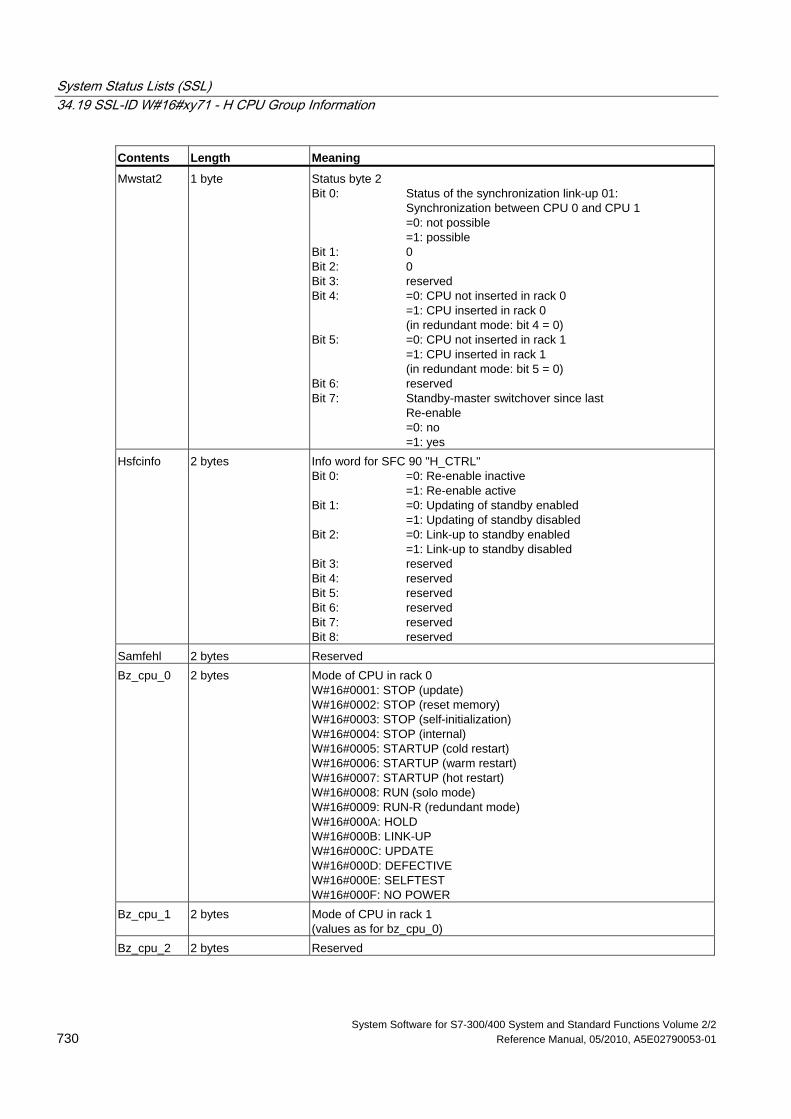
System Status Lists (SSL) 34.19 SSL-ID W#16#xy71 - H CPU Group Information
System Software for S7-300/400 System and Standard Functions Volume 2/2 730 Reference Manual, 05/2010, A5E02790053-01
Contents Length Meaning
Mwstat2 1 byte Status byte 2 Bit 0: Status of the synchronization link-up 01: Synchronization between CPU 0 and CPU 1 =0: not possible =1: possible Bit 1: 0 Bit 2: 0 Bit 3: reserved Bit 4: =0: CPU not inserted in rack 0 =1: CPU inserted in rack 0 (in redundant mode: bit 4 = 0) Bit 5: =0: CPU not inserted in rack 1 =1: CPU inserted in rack 1 (in redundant mode: bit 5 = 0) Bit 6: reserved Bit 7: Standby-master switchover since last Re-enable =0: no =1: yes
Hsfcinfo 2 bytes Info word for SFC 90 "H_CTRL" Bit 0: =0: Re-enable inactive =1: Re-enable active Bit 1: =0: Updating of standby enabled =1: Updating of standby disabled Bit 2: =0: Link-up to standby enabled =1: Link-up to standby disabled Bit 3: reserved Bit 4: reserved Bit 5: reserved Bit 6: reserved Bit 7: reserved Bit 8: reserved
Samfehl 2 bytes Reserved Bz_cpu_0 2 bytes Mode of CPU in rack 0
W#16#0001: STOP (update) W#16#0002: STOP (reset memory) W#16#0003: STOP (self-initialization) W#16#0004: STOP (internal) W#16#0005: STARTUP (cold restart) W#16#0006: STARTUP (warm restart) W#16#0007: STARTUP (hot restart) W#16#0008: RUN (solo mode) W#16#0009: RUN-R (redundant mode) W#16#000A: HOLD W#16#000B: LINK-UP W#16#000C: UPDATE W#16#000D: DEFECTIVE W#16#000E: SELFTEST W#16#000F: NO POWER
Bz_cpu_1 2 bytes Mode of CPU in rack 1 (values as for bz_cpu_0)
Bz_cpu_2 2 bytes Reserved
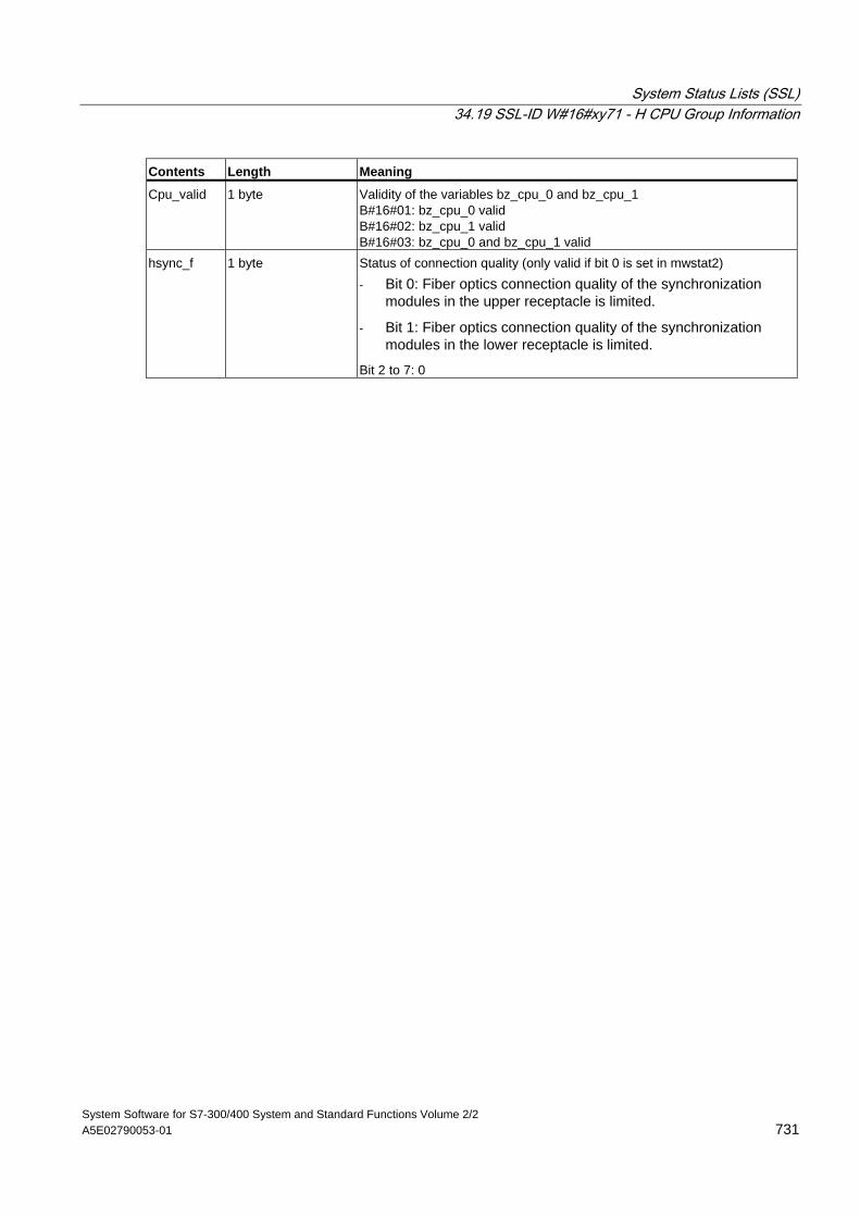
System Status Lists (SSL) 34.19 SSL-ID W#16#xy71 - H CPU Group Information
System Software for S7-300/400 System and Standard Functions Volume 2/2 A5E02790053-01 731
Contents Length Meaning
Cpu_valid 1 byte Validity of the variables bz_cpu_0 and bz_cpu_1 B#16#01: bz_cpu_0 valid B#16#02: bz_cpu_1 valid B#16#03: bz_cpu_0 and bz_cpu_1 valid
hsync_f 1 byte Status of connection quality (only valid if bit 0 is set in mwstat2) - Bit 0: Fiber optics connection quality of the synchronization
modules in the upper receptacle is limited.
- Bit 1: Fiber optics connection quality of the synchronization modules in the lower receptacle is limited.
Bit 2 to 7: 0
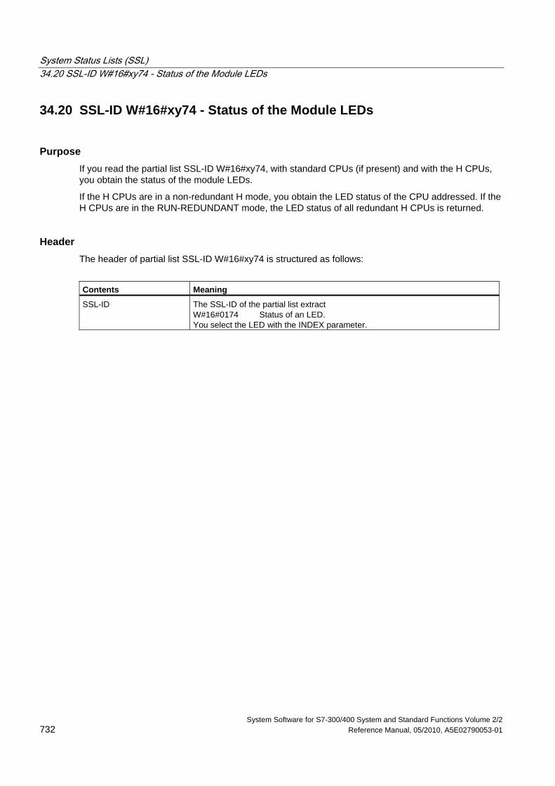
System Status Lists (SSL) 34.20 SSL-ID W#16#xy74 - Status of the Module LEDs
System Software for S7-300/400 System and Standard Functions Volume 2/2 732 Reference Manual, 05/2010, A5E02790053-01
34.20 SSL-ID W#16#xy74 - Status of the Module LEDs
Purpose If you read the partial list SSL-ID W#16#xy74, with standard CPUs (if present) and with the H CPUs, you obtain the status of the module LEDs.
If the H CPUs are in a non-redundant H mode, you obtain the LED status of the CPU addressed. If the H CPUs are in the RUN-REDUNDANT mode, the LED status of all redundant H CPUs is returned.
Header The header of partial list SSL-ID W#16#xy74 is structured as follows:
Contents Meaning
SSL-ID The SSL-ID of the partial list extract W#16#0174 Status of an LED. You select the LED with the INDEX parameter.
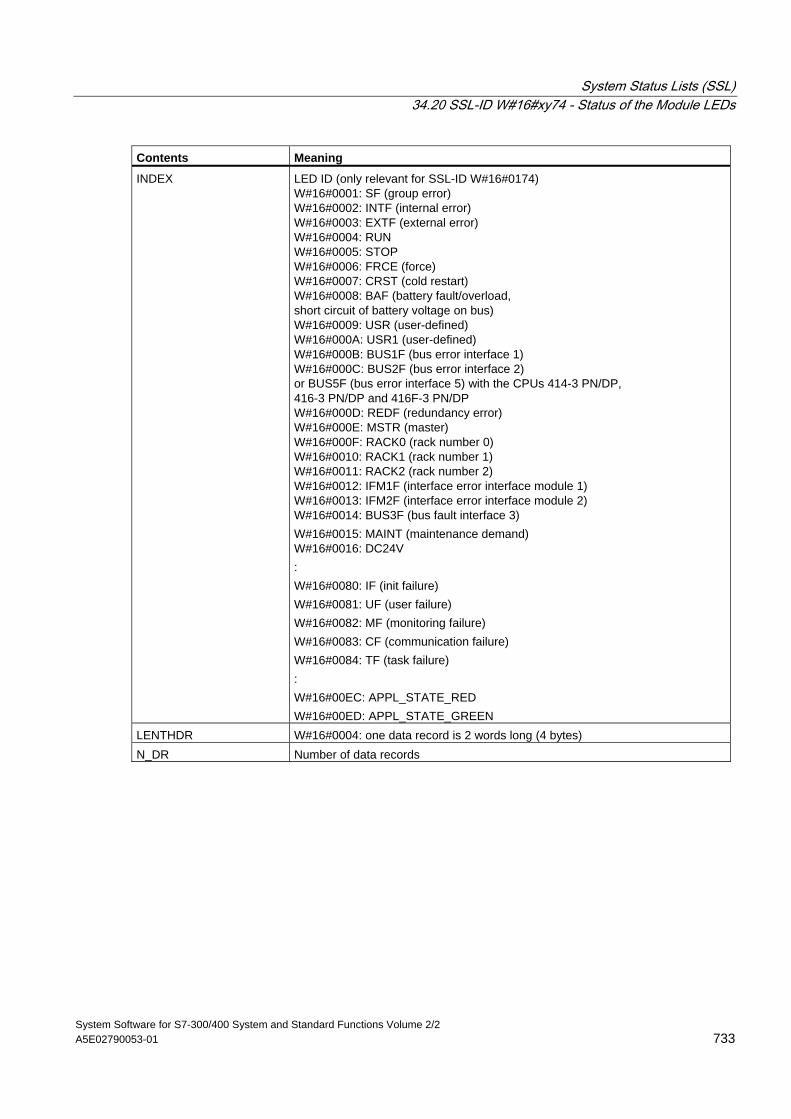
System Status Lists (SSL) 34.20 SSL-ID W#16#xy74 - Status of the Module LEDs
System Software for S7-300/400 System and Standard Functions Volume 2/2 A5E02790053-01 733
Contents Meaning
INDEX LED ID (only relevant for SSL-ID W#16#0174) W#16#0001: SF (group error) W#16#0002: INTF (internal error) W#16#0003: EXTF (external error) W#16#0004: RUN W#16#0005: STOP W#16#0006: FRCE (force) W#16#0007: CRST (cold restart) W#16#0008: BAF (battery fault/overload, short circuit of battery voltage on bus) W#16#0009: USR (user-defined) W#16#000A: USR1 (user-defined) W#16#000B: BUS1F (bus error interface 1) W#16#000C: BUS2F (bus error interface 2) or BUS5F (bus error interface 5) with the CPUs 414-3 PN/DP, 416-3 PN/DP and 416F-3 PN/DP W#16#000D: REDF (redundancy error) W#16#000E: MSTR (master) W#16#000F: RACK0 (rack number 0) W#16#0010: RACK1 (rack number 1) W#16#0011: RACK2 (rack number 2) W#16#0012: IFM1F (interface error interface module 1) W#16#0013: IFM2F (interface error interface module 2) W#16#0014: BUS3F (bus fault interface 3) W#16#0015: MAINT (maintenance demand) W#16#0016: DC24V : W#16#0080: IF (init failure) W#16#0081: UF (user failure) W#16#0082: MF (monitoring failure) W#16#0083: CF (communication failure) W#16#0084: TF (task failure) : W#16#00EC: APPL_STATE_RED W#16#00ED: APPL_STATE_GREEN
LENTHDR W#16#0004: one data record is 2 words long (4 bytes) N_DR Number of data records
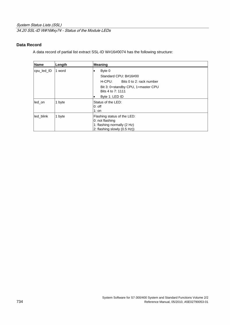
System Status Lists (SSL) 34.20 SSL-ID W#16#xy74 - Status of the Module LEDs
System Software for S7-300/400 System and Standard Functions Volume 2/2 734 Reference Manual, 05/2010, A5E02790053-01
Data Record A data record of partial list extract SSL-ID W#16#0074 has the following structure:
Name Length Meaning
cpu_led_ID 1 word • Byte 0 Standard CPU: B#16#00 H-CPU: Bits 0 to 2: rack number Bit 3: 0=standby CPU, 1=master CPU
Bits 4 to 7: 1111 • Byte 1: LED ID
led_on 1 byte Status of the LED: 0: off 1: on
led_blink 1 byte Flashing status of the LED: 0: not flashing 1: flashing normally (2 Hz) 2: flashing slowly (0.5 Hz))
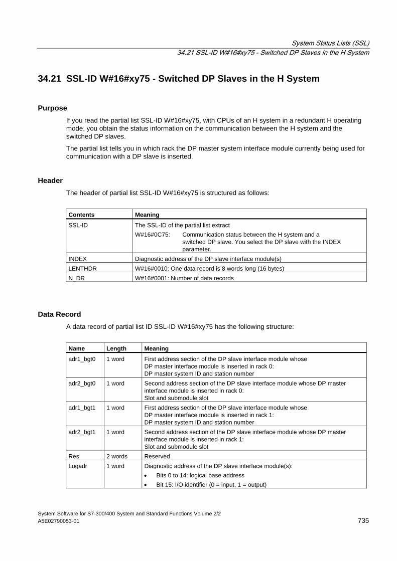
System Status Lists (SSL) 34.21 SSL-ID W#16#xy75 - Switched DP Slaves in the H System
System Software for S7-300/400 System and Standard Functions Volume 2/2 A5E02790053-01 735
34.21 SSL-ID W#16#xy75 - Switched DP Slaves in the H System
Purpose If you read the partial list SSL-ID W#16#xy75, with CPUs of an H system in a redundant H operating mode, you obtain the status information on the communication between the H system and the switched DP slaves.
The partial list tells you in which rack the DP master system interface module currently being used for communication with a DP slave is inserted.
Header The header of partial list SSL-ID W#16#xy75 is structured as follows:
Contents Meaning
SSL-ID The SSL-ID of the partial list extract W#16#0C75: Communication status between the H system and a switched DP slave. You select the DP slave with the INDEX parameter.
INDEX Diagnostic address of the DP slave interface module(s) LENTHDR W#16#0010: One data record is 8 words long (16 bytes) N_DR W#16#0001: Number of data records
Data Record A data record of partial list ID SSL-ID W#16#xy75 has the following structure:
Name Length Meaning
adr1_bgt0 1 word First address section of the DP slave interface module whose DP master interface module is inserted in rack 0: DP master system ID and station number
adr2_bgt0 1 word Second address section of the DP slave interface module whose DP master interface module is inserted in rack 0: Slot and submodule slot
adr1_bgt1 1 word First address section of the DP slave interface module whose DP master interface module is inserted in rack 1: DP master system ID and station number
adr2_bgt1 1 word Second address section of the DP slave interface module whose DP master interface module is inserted in rack 1: Slot and submodule slot
Res 2 words Reserved Logadr 1 word Diagnostic address of the DP slave interface module(s):
• Bits 0 to 14: logical base address • Bit 15: I/O identifier (0 = input, 1 = output)
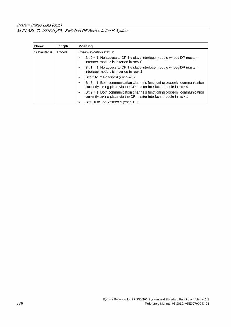
System Status Lists (SSL) 34.21 SSL-ID W#16#xy75 - Switched DP Slaves in the H System
System Software for S7-300/400 System and Standard Functions Volume 2/2 736 Reference Manual, 05/2010, A5E02790053-01
Name Length Meaning
Slavestatus 1 word Communication status: • Bit 0 = 1: No access to DP the slave interface module whose DP master
interface module is inserted in rack 0 • Bit 1 = 1: No access to DP the slave interface module whose DP master
interface module is inserted in rack 1 • Bits 2 to 7: Reserved (each = 0) • Bit 8 = 1: Both communication channels functioning properly; communication
currently taking place via the DP master interface module in rack 0 • Bit 9 = 1: Both communication channels functioning properly; communication
currently taking place via the DP master interface module in rack 1 • Bits 10 to 15: Reserved (each = 0)
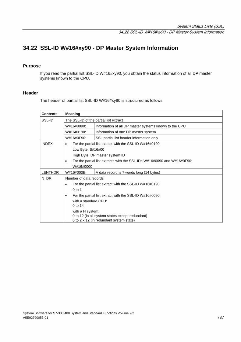
System Status Lists (SSL) 34.22 SSL-ID W#16#xy90 - DP Master System Information
System Software for S7-300/400 System and Standard Functions Volume 2/2 A5E02790053-01 737
34.22 SSL-ID W#16#xy90 - DP Master System Information
Purpose If you read the partial list SSL-ID W#16#xy90, you obtain the status information of all DP master systems known to the CPU.
Header The header of partial list SSL-ID W#16#xy90 is structured as follows:
Contents Meaning
The SSL-ID of the partial list extract W#16#0090: Information of all DP master systems known to the CPU W#16#0190: Information of one DP master system
SSL-ID
W#16#0F90: SSL partial list header information only INDEX • For the partial list extract with the SSL-ID W#16#0190:
Low Byte: B#16#00 High Byte: DP master system ID • For the partial list extracts with the SSL-IDs W#16#0090 and W#16#0F90: W#16#0000
LENTHDR W#16#000E: A data record is 7 words long (14 bytes) N_DR Number of data records
• For the partial list extract with the SSL-ID W#16#0190: 0 to 1 • For the partial list extract with the SSL-ID W#16#0090:
with a standard CPU: 0 to 14 with a H system: 0 to 12 (in all system states except redundant) 0 to 2 x 12 (in redundant system state)
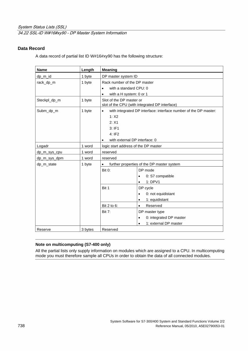
System Status Lists (SSL) 34.22 SSL-ID W#16#xy90 - DP Master System Information
System Software for S7-300/400 System and Standard Functions Volume 2/2 738 Reference Manual, 05/2010, A5E02790053-01
Data Record A data record of partial list ID W#16#xy90 has the following structure:
Name Length Meaning
dp_m_id 1 byte DP master system ID rack_dp_m 1 byte Rack number of the DP master
• with a standard CPU: 0 • with a H system: 0 or 1
Steckpl_dp_m 1 byte Slot of the DP master or slot of the CPU (with integrated DP interface)
Subm_dp_m 1 byte • with integrated DP interface: interface number of the DP master: 1: X2 2: X1 3: IF1 4: IF2 • with external DP interface: 0
Logadr 1 word logic start address of the DP master dp_m_sys_cpu 1 word reserved dp_m_sys_dpm 1 word reserved
• further properties of the DP master system Bit 0: DP mode
• 0: S7 compatible • 1: DPV1
Bit 1 DP cycle • 0: not equidistant • 1: equidistant
Bit 2 to 6: • Reserved
dp_m_state 1 byte
Bit 7: DP master type • 0: integrated DP master • 1: external DP master
Reserve 3 bytes Reserved
Note on multicomputing (S7-400 only)
All the partial lists only supply information on modules which are assigned to a CPU. In multicomputing mode you must therefore sample all CPUs in order to obtain the data of all connected modules.
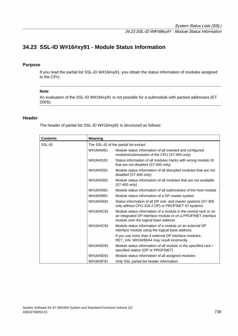
System Status Lists (SSL) 34.23 SSL-ID W#16#xy91 - Module Status Information
System Software for S7-300/400 System and Standard Functions Volume 2/2 A5E02790053-01 739
34.23 SSL-ID W#16#xy91 - Module Status Information
Purpose If you read the partial list SSL-ID W#16#xy91, you obtain the status information of modules assigned to the CPU.
Note
An evaluation of the SSL-ID W#16#xy91 is not possible for a submodule with packed addresses (ET 200S).
Header The header of partial list SSL-ID W#16#xy91 is structured as follows:
Contents Meaning
SSL-ID The SSL-ID of the partial list extract W#16#0091 Module status information of all inserted and configured
modules/submodules of the CPU (S7-400 only) W#16#0191 Status information of all modules /racks with wrong module ID
that are not disabled (S7-400 only) W#16#0291 Module status information of all disrupted modules that are not
disabled (S7-400 only) W#16#0391 Module status information of all modules that are not available
(S7-400 only) W#16#0591 Module status information of all submodules of the host module W#16#0991 Module status information of a DP master system W#16#0A91 Status information of all DP sub- and master systems (S7-300
only without CPU 318-2 DP) or PROFINET IO systems W#16#0C91 Module status information of a module in the central rack or on
an integrated DP interface module or on a PROFINET interface module over the logical base address
W#16#4C91 Module status information of a module on an external DP interface module using the logical base address
If you use more than 4 external DP interface modules, RET_VAL W#16#80A4 may result incorrectly.
W#16#0D91 Module status information of all module in the specified rack / specified station (DP or PROFINET)
W#16#0E91 Module status information of all assigned modules W#16#0F91 Only SSL partial list header information
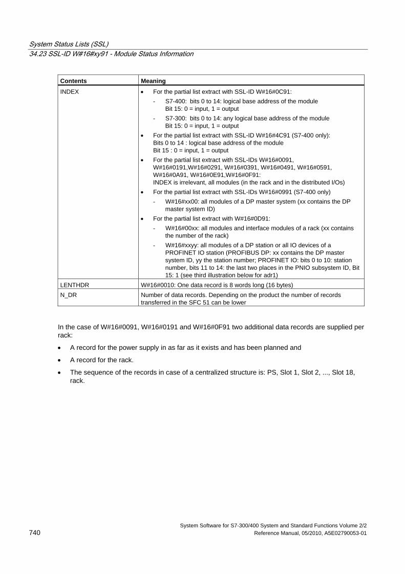
System Status Lists (SSL) 34.23 SSL-ID W#16#xy91 - Module Status Information
System Software for S7-300/400 System and Standard Functions Volume 2/2 740 Reference Manual, 05/2010, A5E02790053-01
Contents Meaning
INDEX • For the partial list extract with SSL-ID W#16#0C91: - S7-400: bits 0 to 14: logical base address of the module
Bit 15: 0 = input, 1 = output - S7-300: bits 0 to 14: any logical base address of the module
Bit 15: 0 = input, 1 = output • For the partial list extract with SSL-ID W#16#4C91 (S7-400 only):
Bits 0 to 14 : logical base address of the module Bit 15 : 0 = input, 1 = output
• For the partial list extract with SSL-IDs W#16#0091, W#16#0191,W#16#0291, W#16#0391, W#16#0491, W#16#0591, W#16#0A91, W#16#0E91,W#16#0F91: INDEX is irrelevant, all modules (in the rack and in the distributed I/Os)
• For the partial list extract with SSL-IDs W#16#0991 (S7-400 only) - W#16#xx00: all modules of a DP master system (xx contains the DP
master system ID) • For the partial list extract with W#16#0D91:
- W#16#00xx: all modules and interface modules of a rack (xx contains the number of the rack)
- W#16#xxyy: all modules of a DP station or all IO devices of a PROFINET IO station (PROFIBUS DP: xx contains the DP master system ID, yy the station number; PROFINET IO: bits 0 to 10: station number, bits 11 to 14: the last two places in the PNIO subsystem ID, Bit 15: 1 (see third illustration below for adr1)
LENTHDR W#16#0010: One data record is 8 words long (16 bytes) N_DR Number of data records. Depending on the product the number of records
transferred in the SFC 51 can be lower
In the case of W#16#0091, W#16#0191 and W#16#0F91 two additional data records are supplied per rack:
• A record for the power supply in as far as it exists and has been planned and
• A record for the rack.
• The sequence of the records in case of a centralized structure is: PS, Slot 1, Slot 2, ..., Slot 18, rack.
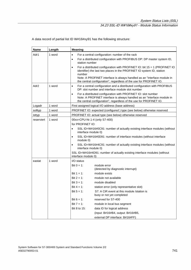
System Status Lists (SSL) 34.23 SSL-ID W#16#xy91 - Module Status Information
System Software for S7-300/400 System and Standard Functions Volume 2/2 A5E02790053-01 741
A data record of partial list ID W#16#xy91 has the following structure:
Name Length Meaning
Adr1 1 word • For a central configuration: number of the rack • For a distributed configuration with PROFIBUS DP: DP master system ID,
station number • For a distributed configuration with PROFINET IO: bit 15 = 1 (PROFINET IO
identifier) the last two places in the PROFINET IO system ID, station number Note: A PROFINET interface is always handled as an "interface module in the central configuration", regardless of the use for PROFINET IO.
Adr2 1 word • For a central configuration and a distributed configuration with PROFIBUS DP: slot number and interface module slot number
• For a distributed configuration with PROFINET IO: slot number Note: A PROFINET interface is always handled as an "interface module in the central configuration", regardless of the use for PROFINET IO.
Logadr 1 word First assigned logical I/O address (base address) solltyp 1 word PROFINET IO: expected (configured ) type (see below) otherwise reserved isttyp 1 word PROFINET IO: actual type (see below) otherwise reserved reserviert 1 word 00xx=CPU-Nr.1-4 (only S7-400)
for PROFINET IO: • SSL ID=W#16#0C91: number of actually existing interface modules (without
interface module 0) • SSL ID=W#16#0D91: number of interface modules (without interface
module 0) • SSL ID=W#16#4C91: number of actually existing interface modules (without
interface module 0) SSL ID=W#16#4D91: number of actually existing interface modules (without interface module 0)
eastat 1 word I/O status Bit 0 = 1: module error (detected by diagnostic interrupt) Bit 1 = 1: module exists Bit 2 = 1: module not available Bit 3 = 1: module disabled Bit 4 = 1: station error (only representative slot) Bit 5 = 1: S7: A CiR event at this module /station is busy or not yet completed Bit 6 = 1: reserved for S7-400 Bit 7 = 1: module in local bus segment Bit 8 to 15: data ID for logical address (input: B#16#B4, output: B#16#B5, external DP interface: B#16#FF)
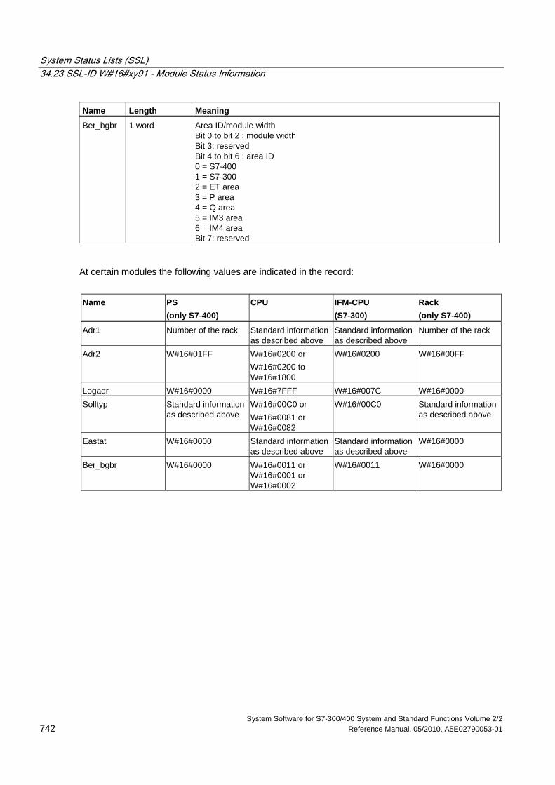
System Status Lists (SSL) 34.23 SSL-ID W#16#xy91 - Module Status Information
System Software for S7-300/400 System and Standard Functions Volume 2/2 742 Reference Manual, 05/2010, A5E02790053-01
Name Length Meaning
Ber_bgbr 1 word Area ID/module width Bit 0 to bit 2 : module width Bit 3: reserved Bit 4 to bit 6 : area ID 0 = S7-400 1 = S7-300 2 = ET area 3 = P area 4 = Q area 5 = IM3 area 6 = IM4 area Bit 7: reserved
At certain modules the following values are indicated in the record:
Name PS
(only S7-400) CPU IFM-CPU
(S7-300) Rack (only S7-400)
Adr1 Number of the rack Standard information as described above
Standard information as described above
Number of the rack
Adr2 W#16#01FF W#16#0200 or W#16#0200 to W#16#1800
W#16#0200 W#16#00FF
Logadr W#16#0000 W#16#7FFF W#16#007C W#16#0000 Solltyp Standard information
as described above W#16#00C0 or W#16#0081 or W#16#0082
W#16#00C0 Standard information as described above
Eastat W#16#0000 Standard information as described above
Standard information as described above
W#16#0000
Ber_bgbr W#16#0000 W#16#0011 or W#16#0001 or W#16#0002
W#16#0011 W#16#0000
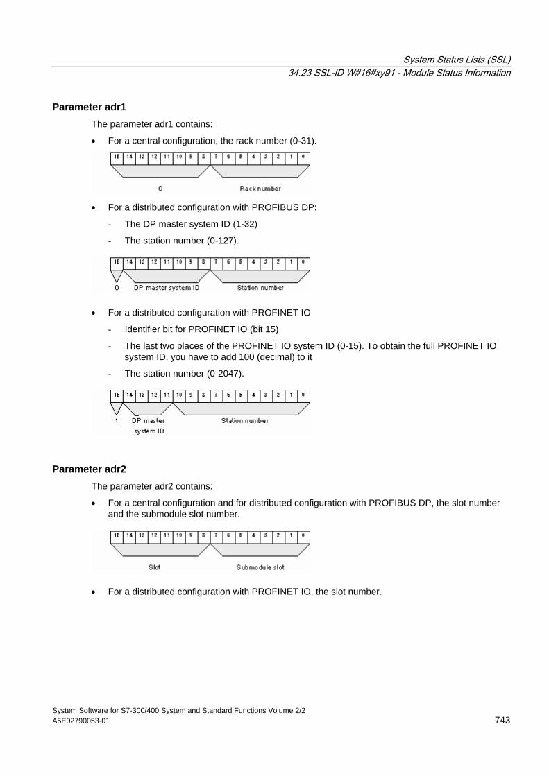
System Status Lists (SSL) 34.23 SSL-ID W#16#xy91 - Module Status Information
System Software for S7-300/400 System and Standard Functions Volume 2/2 A5E02790053-01 743
Parameter adr1 The parameter adr1 contains:
• For a central configuration, the rack number (0-31).
• For a distributed configuration with PROFIBUS DP:
- The DP master system ID (1-32)
- The station number (0-127).
• For a distributed configuration with PROFINET IO
- Identifier bit for PROFINET IO (bit 15)
- The last two places of the PROFINET IO system ID (0-15). To obtain the full PROFINET IO system ID, you have to add 100 (decimal) to it
- The station number (0-2047).
Parameter adr2 The parameter adr2 contains:
• For a central configuration and for distributed configuration with PROFIBUS DP, the slot number and the submodule slot number.
• For a distributed configuration with PROFINET IO, the slot number.
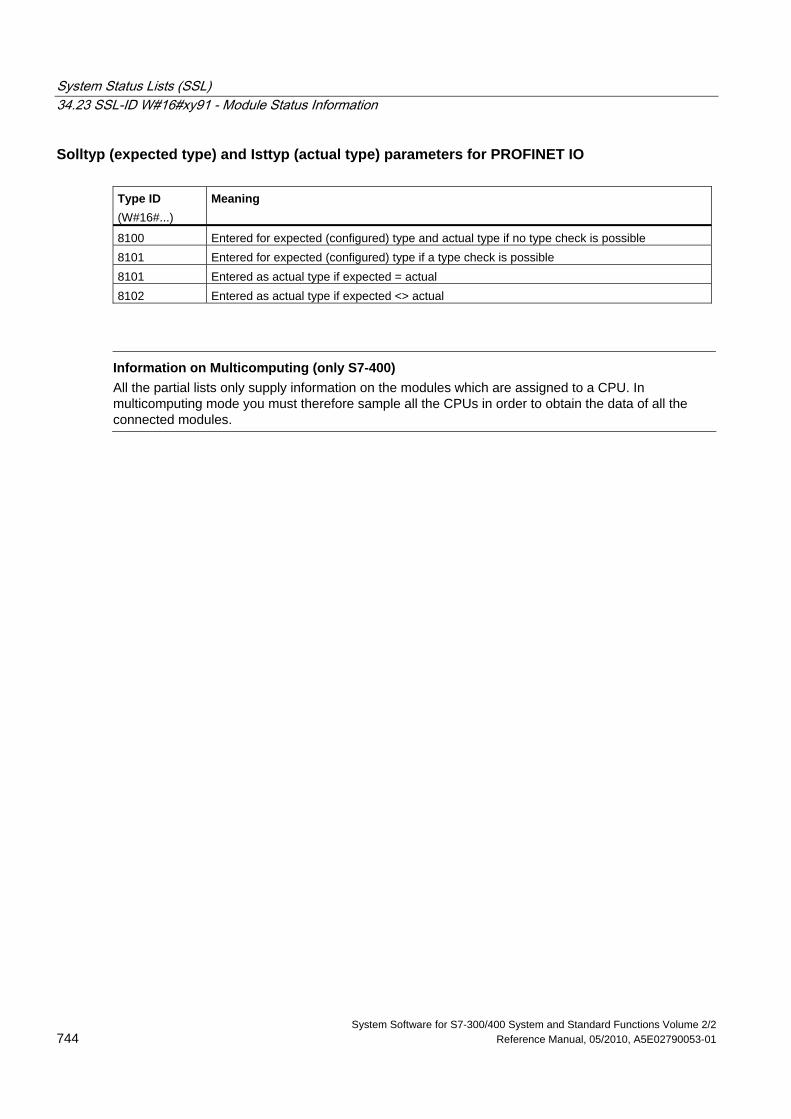
System Status Lists (SSL) 34.23 SSL-ID W#16#xy91 - Module Status Information
System Software for S7-300/400 System and Standard Functions Volume 2/2 744 Reference Manual, 05/2010, A5E02790053-01
Solltyp (expected type) and Isttyp (actual type) parameters for PROFINET IO Type ID (W#16#...)
Meaning
8100 Entered for expected (configured) type and actual type if no type check is possible 8101 Entered for expected (configured) type if a type check is possible 8101 Entered as actual type if expected = actual 8102 Entered as actual type if expected <> actual
Information on Multicomputing (only S7-400)
All the partial lists only supply information on the modules which are assigned to a CPU. In multicomputing mode you must therefore sample all the CPUs in order to obtain the data of all the connected modules.
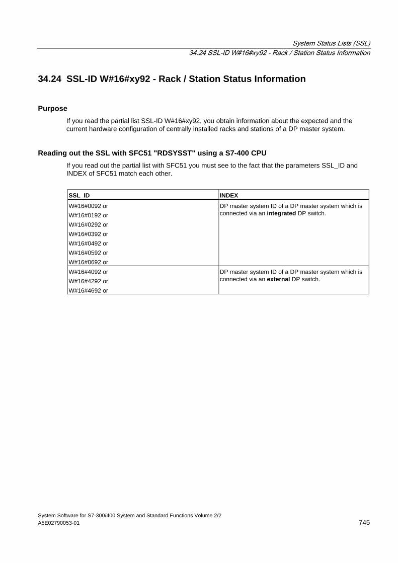
System Status Lists (SSL) 34.24 SSL-ID W#16#xy92 - Rack / Station Status Information
System Software for S7-300/400 System and Standard Functions Volume 2/2 A5E02790053-01 745
34.24 SSL-ID W#16#xy92 - Rack / Station Status Information
Purpose If you read the partial list SSL-ID W#16#xy92, you obtain information about the expected and the current hardware configuration of centrally installed racks and stations of a DP master system.
Reading out the SSL with SFC51 "RDSYSST" using a S7-400 CPU If you read out the partial list with SFC51 you must see to the fact that the parameters SSL_ID and INDEX of SFC51 match each other.
SSL_ID INDEX
W#16#0092 or W#16#0192 or W#16#0292 or W#16#0392 or W#16#0492 or W#16#0592 or W#16#0692 or
DP master system ID of a DP master system which is connected via an integrated DP switch.
W#16#4092 or W#16#4292 or W#16#4692 or
DP master system ID of a DP master system which is connected via an external DP switch.
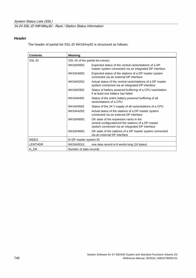
System Status Lists (SSL) 34.24 SSL-ID W#16#xy92 - Rack / Station Status Information
System Software for S7-300/400 System and Standard Functions Volume 2/2 746 Reference Manual, 05/2010, A5E02790053-01
Header The header of partial list SSL-ID W#16#xy92 is structured as follows:
Contents Meaning
SSL-ID SSL-ID of the partial list extract: W#16#0092: Expected status of the central racks/stations of a DP master system connected via an integrated DP interface W#16#4092: Expected status of the stations of a DP master system connected via an external DP interface W#16#0292: Actual status of the central racks/stations of a DP master system connected via an integrated DP interface W#16#0392 Status of battery powered buffering of a CPU rack/station if at least one battery has failed W#16#0492 Status of the entire battery powered buffering of all racks/stations of a CPU W#16#0592 Status of the 24 V supply of all racks/stations of a CPU W#16#4292: Actual status of the stations of a DP master system connected via an external DP interface W#16#0692: OK state of the expansion racks in the central configuration/of the stations of a DP master system connected via an integrated DP interface W#16#4692: OK state of the stations of a DP master system connected via an external DP interface
INDEX 0/ DP master system ID LENTHDR W#16#0010: one data record is 8 words long (16 bytes) N_DR Number of data records
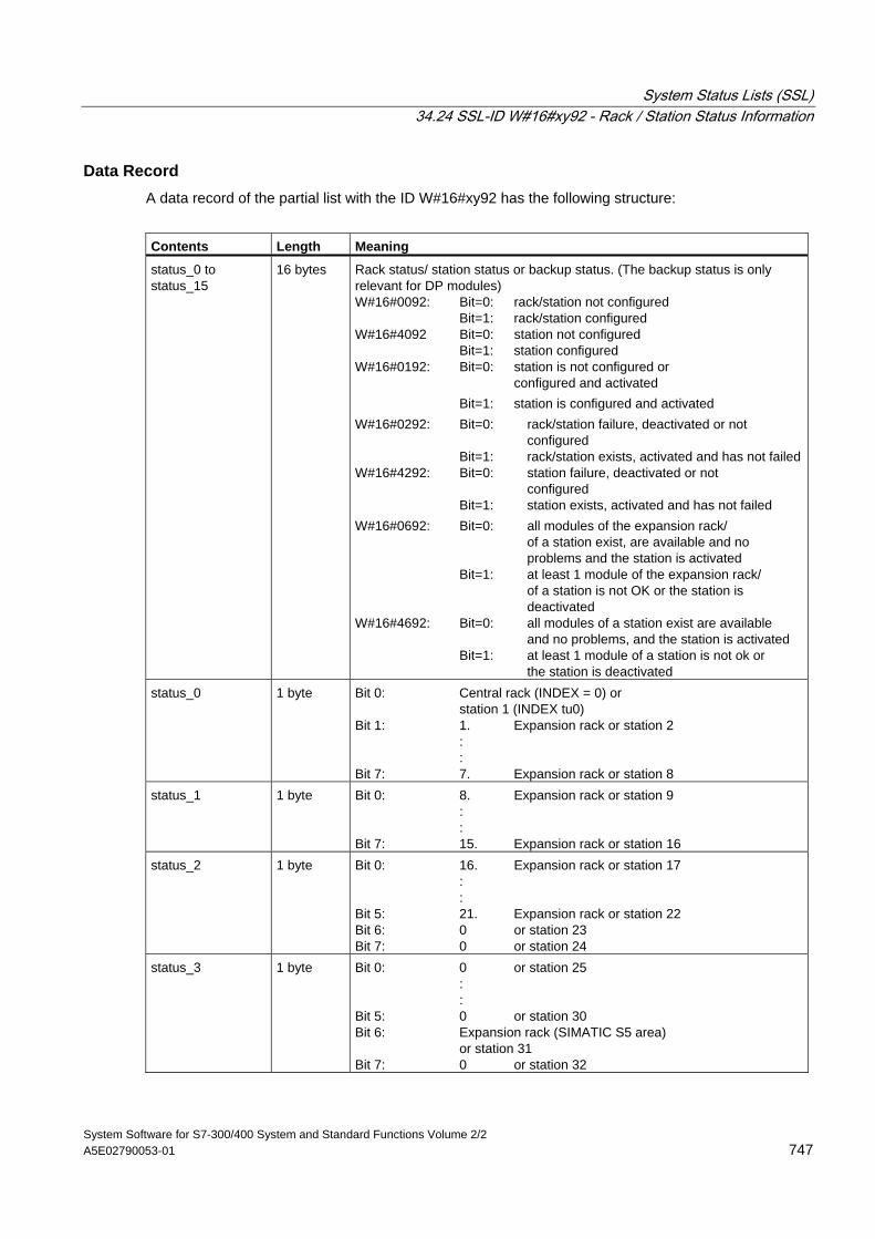
System Status Lists (SSL) 34.24 SSL-ID W#16#xy92 - Rack / Station Status Information
System Software for S7-300/400 System and Standard Functions Volume 2/2 A5E02790053-01 747
Data Record A data record of the partial list with the ID W#16#xy92 has the following structure:
Contents Length Meaning
status_0 to status_15
16 bytes Rack status/ station status or backup status. (The backup status is only relevant for DP modules) W#16#0092: Bit=0: rack/station not configured Bit=1: rack/station configured W#16#4092 Bit=0: station not configured Bit=1: station configured W#16#0192: Bit=0: station is not configured or configured and activated Bit=1: station is configured and activated W#16#0292: Bit=0: rack/station failure, deactivated or not configured Bit=1: rack/station exists, activated and has not failedW#16#4292: Bit=0: station failure, deactivated or not configured Bit=1: station exists, activated and has not failed W#16#0692: Bit=0: all modules of the expansion rack/ of a station exist, are available and no problems and the station is activated Bit=1: at least 1 module of the expansion rack/ of a station is not OK or the station is deactivated W#16#4692: Bit=0: all modules of a station exist are available and no problems, and the station is activated Bit=1: at least 1 module of a station is not ok or the station is deactivated
status_0 1 byte Bit 0: Central rack (INDEX = 0) or station 1 (INDEX tu0) Bit 1: 1. Expansion rack or station 2 : : Bit 7: 7. Expansion rack or station 8
status_1 1 byte Bit 0: 8. Expansion rack or station 9 : : Bit 7: 15. Expansion rack or station 16
status_2 1 byte Bit 0: 16. Expansion rack or station 17 : : Bit 5: 21. Expansion rack or station 22 Bit 6: 0 or station 23 Bit 7: 0 or station 24
status_3 1 byte Bit 0: 0 or station 25 : : Bit 5: 0 or station 30 Bit 6: Expansion rack (SIMATIC S5 area) or station 31 Bit 7: 0 or station 32
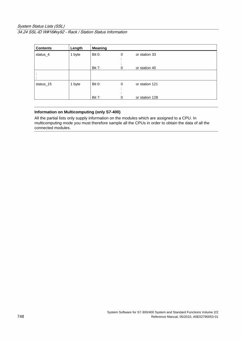
System Status Lists (SSL) 34.24 SSL-ID W#16#xy92 - Rack / Station Status Information
System Software for S7-300/400 System and Standard Functions Volume 2/2 748 Reference Manual, 05/2010, A5E02790053-01
Contents Length Meaning
status_4 1 byte Bit 0: 0 or station 33 : : Bit 7: 0 or station 40
: :
status_15 1 byte Bit 0: 0 or station 121 : : Bit 7: 0 or station 128
Information on Multicomputing (only S7-400)
All the partial lists only supply information on the modules which are assigned to a CPU. In multicomputing mode you must therefore sample all the CPUs in order to obtain the data of all the connected modules.
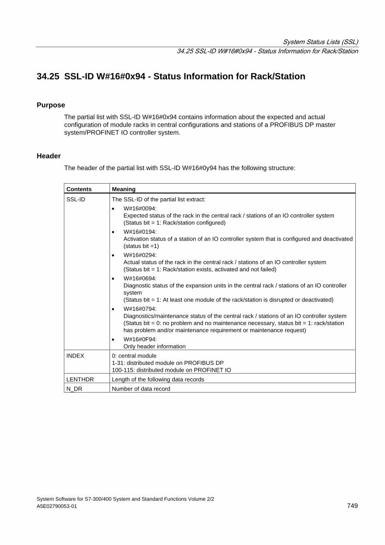
System Status Lists (SSL) 34.25 SSL-ID W#16#0x94 - Status Information for Rack/Station
System Software for S7-300/400 System and Standard Functions Volume 2/2 A5E02790053-01 749
34.25 SSL-ID W#16#0x94 - Status Information for Rack/Station
Purpose The partial list with SSL-ID W#16#0x94 contains information about the expected and actual configuration of module racks in central configurations and stations of a PROFIBUS DP master system/PROFINET IO controller system.
Header The header of the partial list with SSL-ID W#16#0y94 has the following structure:
Contents Meaning
SSL-ID The SSL-ID of the partial list extract: • W#16#0094:
Expected status of the rack in the central rack / stations of an IO controller system (Status bit = 1: Rack/station configured)
• W#16#0194: Activation status of a station of an IO controller system that is configured and deactivated (status bit =1)
• W#16#0294: Actual status of the rack in the central rack / stations of an IO controller system (Status bit = 1: Rack/station exists, activated and not failed)
• W#16#0694: Diagnostic status of the expansion units in the central rack / stations of an IO controller system (Status bit = 1: At least one module of the rack/station is disrupted or deactivated)
• W#16#0794: Diagnostics/maintenance status of the central rack / stations of an IO controller system (Status bit = 0: no problem and no maintenance necessary, status bit = 1: rack/station has problem and/or maintenance requirement or maintenance request)
• W#16#0F94: Only header information
INDEX 0: central module 1-31: distributed module on PROFIBUS DP 100-115: distributed module on PROFINET IO
LENTHDR Length of the following data records N_DR Number of data record
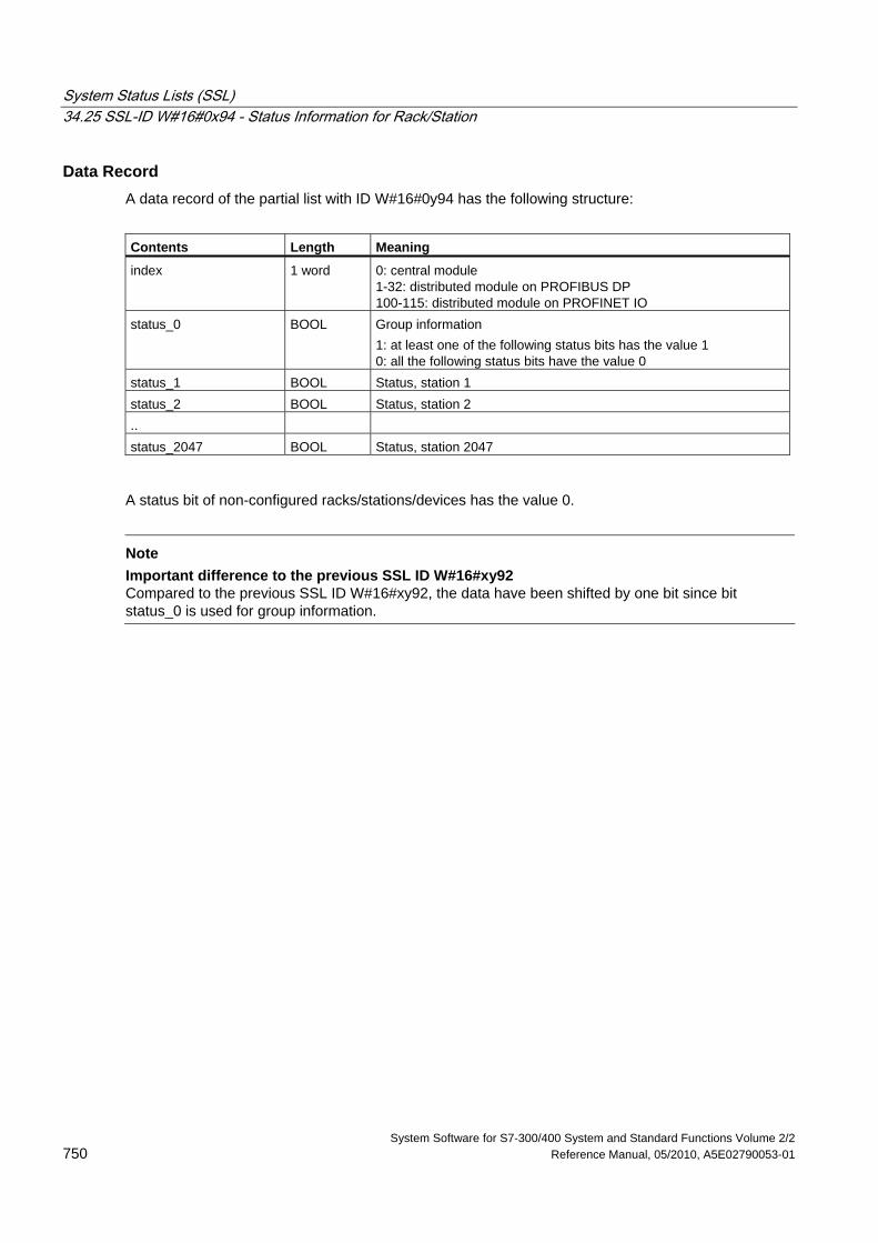
System Status Lists (SSL) 34.25 SSL-ID W#16#0x94 - Status Information for Rack/Station
System Software for S7-300/400 System and Standard Functions Volume 2/2 750 Reference Manual, 05/2010, A5E02790053-01
Data Record A data record of the partial list with ID W#16#0y94 has the following structure:
Contents Length Meaning
index 1 word 0: central module 1-32: distributed module on PROFIBUS DP 100-115: distributed module on PROFINET IO
status_0 BOOL Group information 1: at least one of the following status bits has the value 1 0: all the following status bits have the value 0
status_1 BOOL Status, station 1 status_2 BOOL Status, station 2 .. status_2047 BOOL Status, station 2047
A status bit of non-configured racks/stations/devices has the value 0.
Note
Important difference to the previous SSL ID W#16#xy92 Compared to the previous SSL ID W#16#xy92, the data have been shifted by one bit since bit status_0 is used for group information.
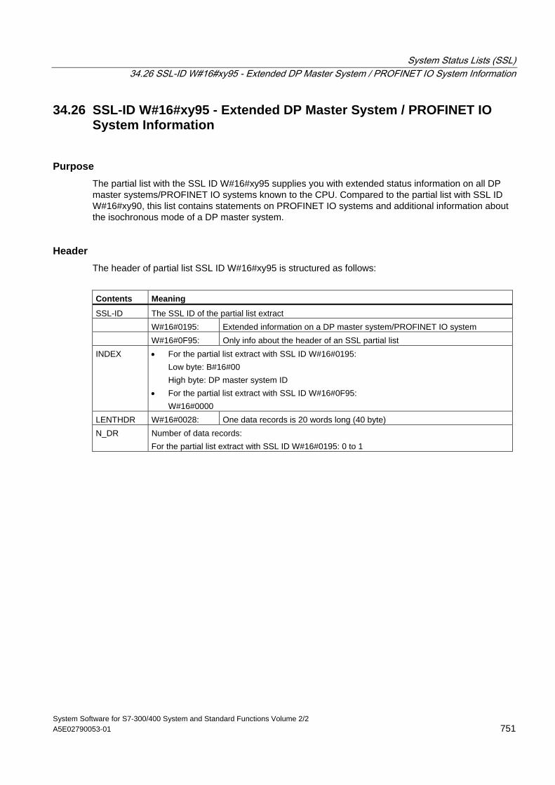
System Status Lists (SSL) 34.26 SSL-ID W#16#xy95 - Extended DP Master System / PROFINET IO System Information
System Software for S7-300/400 System and Standard Functions Volume 2/2 A5E02790053-01 751
34.26 SSL-ID W#16#xy95 - Extended DP Master System / PROFINET IO System Information
Purpose The partial list with the SSL ID W#16#xy95 supplies you with extended status information on all DP master systems/PROFINET IO systems known to the CPU. Compared to the partial list with SSL ID W#16#xy90, this list contains statements on PROFINET IO systems and additional information about the isochronous mode of a DP master system.
Header The header of partial list SSL ID W#16#xy95 is structured as follows:
Contents Meaning
SSL-ID The SSL ID of the partial list extract W#16#0195: Extended information on a DP master system/PROFINET IO system W#16#0F95: Only info about the header of an SSL partial list INDEX • For the partial list extract with SSL ID W#16#0195:
Low byte: B#16#00 High byte: DP master system ID • For the partial list extract with SSL ID W#16#0F95: W#16#0000
LENTHDR W#16#0028: One data records is 20 words long (40 byte) N_DR Number of data records:
For the partial list extract with SSL ID W#16#0195: 0 to 1
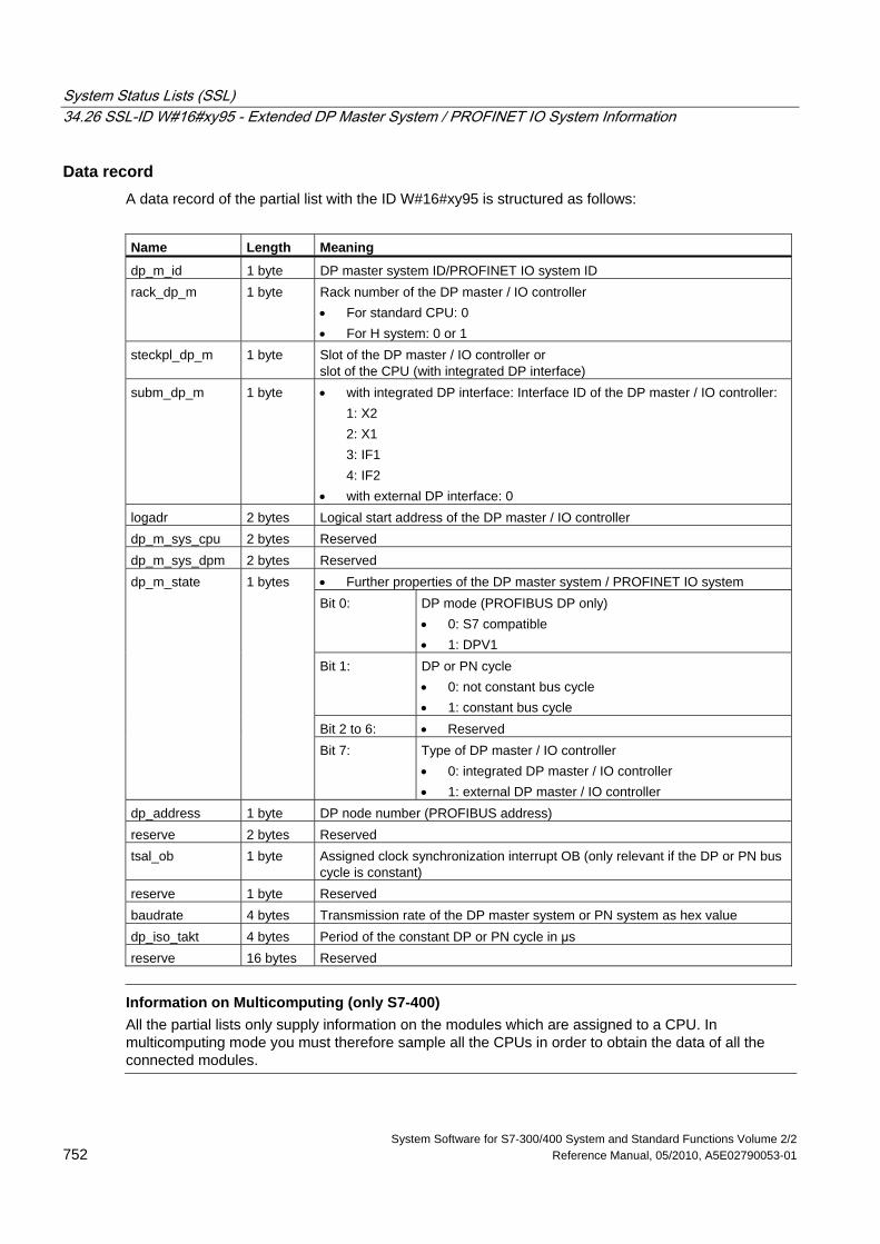
System Status Lists (SSL) 34.26 SSL-ID W#16#xy95 - Extended DP Master System / PROFINET IO System Information
System Software for S7-300/400 System and Standard Functions Volume 2/2 752 Reference Manual, 05/2010, A5E02790053-01
Data record A data record of the partial list with the ID W#16#xy95 is structured as follows:
Name Length Meaning
dp_m_id 1 byte DP master system ID/PROFINET IO system ID rack_dp_m 1 byte Rack number of the DP master / IO controller
• For standard CPU: 0 • For H system: 0 or 1
steckpl_dp_m 1 byte Slot of the DP master / IO controller or slot of the CPU (with integrated DP interface)
subm_dp_m 1 byte • with integrated DP interface: Interface ID of the DP master / IO controller: 1: X2 2: X1 3: IF1 4: IF2
• with external DP interface: 0 logadr 2 bytes Logical start address of the DP master / IO controller dp_m_sys_cpu 2 bytes Reserved dp_m_sys_dpm 2 bytes Reserved
• Further properties of the DP master system / PROFINET IO system Bit 0: DP mode (PROFIBUS DP only)
• 0: S7 compatible • 1: DPV1
Bit 1: DP or PN cycle • 0: not constant bus cycle • 1: constant bus cycle
Bit 2 to 6: • Reserved
dp_m_state 1 bytes
Bit 7: Type of DP master / IO controller • 0: integrated DP master / IO controller • 1: external DP master / IO controller
dp_address 1 byte DP node number (PROFIBUS address) reserve 2 bytes Reserved tsal_ob 1 byte Assigned clock synchronization interrupt OB (only relevant if the DP or PN bus
cycle is constant) reserve 1 byte Reserved baudrate 4 bytes Transmission rate of the DP master system or PN system as hex value dp_iso_takt 4 bytes Period of the constant DP or PN cycle in μs reserve 16 bytes Reserved
Information on Multicomputing (only S7-400)
All the partial lists only supply information on the modules which are assigned to a CPU. In multicomputing mode you must therefore sample all the CPUs in order to obtain the data of all the connected modules.

System Status Lists (SSL) 34.27 SSL-ID W#16#xy96 - PROFINET IO and PROFIBUS DP Module Status Information
System Software for S7-300/400 System and Standard Functions Volume 2/2 A5E02790053-01 753
34.27 SSL-ID W#16#xy96 - PROFINET IO and PROFIBUS DP Module Status Information
Purpose The partial list with SSL-ID W#16#xy96 contains status information on all the modules assigned to the CPU.
The information in the partial list with SSL-ID W#16#xy96 supplements SSL-ID W#16#xy91 and provides additional status data on submodules and interface modules.
It provides information specific to PROFINET IO as well as information on PROFIBUS DP modules and central modules.
Header The header of the partial list with SSL-ID W#16#xy96 has the following structure:
Contents Meaning
SSL-ID The SSL-ID of the partial list extract • W#16#0696
Module status information of all submodules of a specified module (with PROFIBUS DP and central modules, the submodule level does not exist).
• W#16#0C96 Module status information of a module/submodule located centrally or on a PROFIBUS DP/PROFINET interface module over the start address.
INDEX Bits 0 to 14: address of the module Bit 15: 0 = input, 1 = output
LENTHDR Length of the following data record N_DR Number of data records
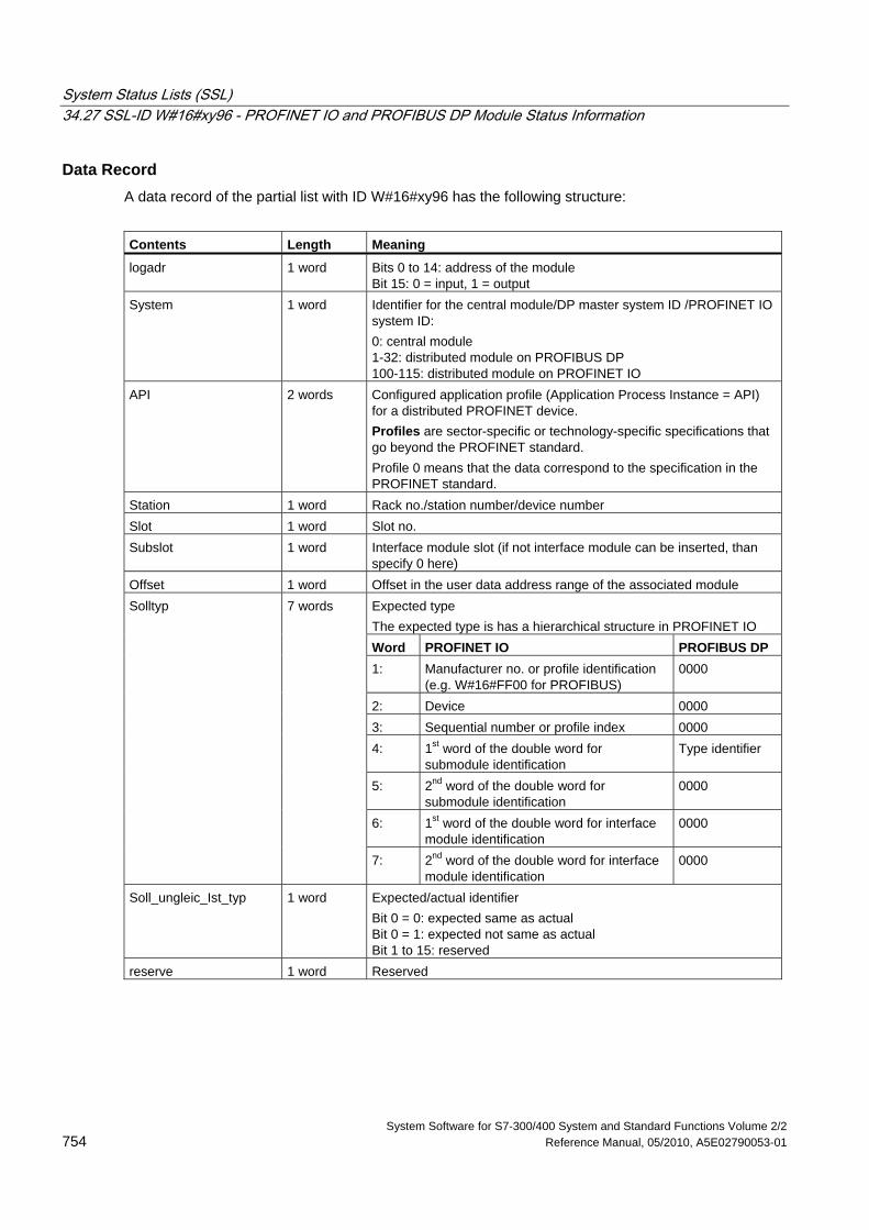
System Status Lists (SSL) 34.27 SSL-ID W#16#xy96 - PROFINET IO and PROFIBUS DP Module Status Information
System Software for S7-300/400 System and Standard Functions Volume 2/2 754 Reference Manual, 05/2010, A5E02790053-01
Data Record A data record of the partial list with ID W#16#xy96 has the following structure:
Contents Length Meaning
logadr 1 word Bits 0 to 14: address of the module Bit 15: 0 = input, 1 = output
System 1 word Identifier for the central module/DP master system ID /PROFINET IO system ID: 0: central module 1-32: distributed module on PROFIBUS DP 100-115: distributed module on PROFINET IO
API 2 words Configured application profile (Application Process Instance = API) for a distributed PROFINET device. Profiles are sector-specific or technology-specific specifications that go beyond the PROFINET standard. Profile 0 means that the data correspond to the specification in the PROFINET standard.
Station 1 word Rack no./station number/device number Slot 1 word Slot no. Subslot 1 word Interface module slot (if not interface module can be inserted, than
specify 0 here) Offset 1 word Offset in the user data address range of the associated module
Expected type The expected type is has a hierarchical structure in PROFINET IO Word PROFINET IO PROFIBUS DP 1: Manufacturer no. or profile identification
(e.g. W#16#FF00 for PROFIBUS) 0000
2: Device 0000 3: Sequential number or profile index 0000 4: 1st word of the double word for
submodule identification Type identifier
5: 2nd word of the double word for submodule identification
0000
6: 1st word of the double word for interface module identification
0000
Solltyp 7 words
7: 2nd word of the double word for interface module identification
0000
Soll_ungleic_Ist_typ 1 word Expected/actual identifier Bit 0 = 0: expected same as actual Bit 0 = 1: expected not same as actual Bit 1 to 15: reserved
reserve 1 word Reserved
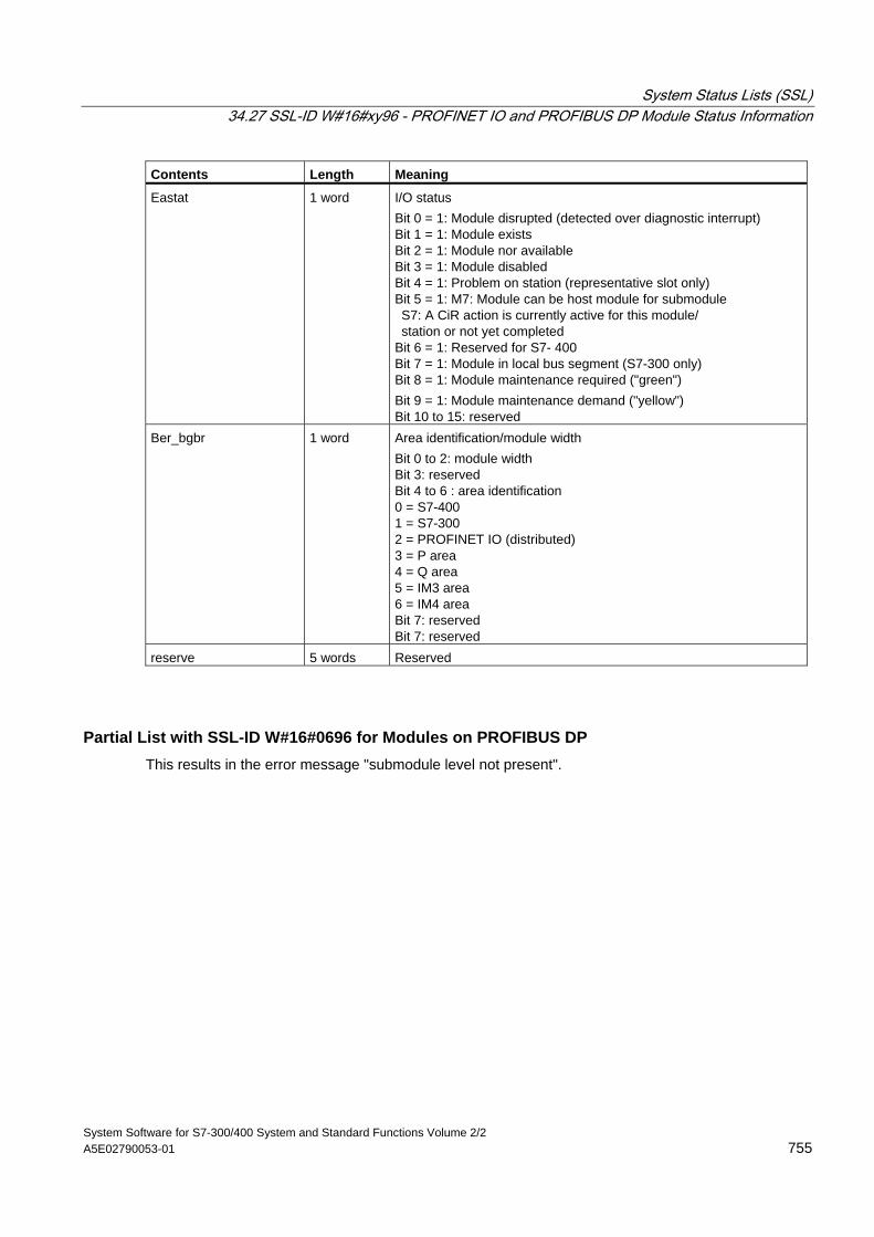
System Status Lists (SSL) 34.27 SSL-ID W#16#xy96 - PROFINET IO and PROFIBUS DP Module Status Information
System Software for S7-300/400 System and Standard Functions Volume 2/2 A5E02790053-01 755
Contents Length Meaning
Eastat 1 word I/O status Bit 0 = 1: Module disrupted (detected over diagnostic interrupt) Bit 1 = 1: Module exists Bit 2 = 1: Module nor available Bit 3 = 1: Module disabled Bit 4 = 1: Problem on station (representative slot only) Bit 5 = 1: M7: Module can be host module for submodule S7: A CiR action is currently active for this module/ station or not yet completed Bit 6 = 1: Reserved for S7- 400 Bit 7 = 1: Module in local bus segment (S7-300 only) Bit 8 = 1: Module maintenance required ("green") Bit 9 = 1: Module maintenance demand ("yellow") Bit 10 to 15: reserved
Ber_bgbr 1 word Area identification/module width Bit 0 to 2: module width Bit 3: reserved Bit 4 to 6 : area identification 0 = S7-400 1 = S7-300 2 = PROFINET IO (distributed) 3 = P area 4 = Q area 5 = IM3 area 6 = IM4 area Bit 7: reserved Bit 7: reserved
reserve 5 words Reserved
Partial List with SSL-ID W#16#0696 for Modules on PROFIBUS DP This results in the error message "submodule level not present".
System Status Lists (SSL) 34.28 SSL-ID W#16#xy9C - Tool Changer Information (PROFINET IO)
System Software for S7-300/400 System and Standard Functions Volume 2/2 756 Reference Manual, 05/2010, A5E02790053-01
34.28 SSL-ID W#16#xy9C - Tool Changer Information (PROFINET IO)
Purpose A partial list with SSL-ID W#16#xy9C provides you with information on the configured tool changer and its tools.
Tool changers are IO devices that manage tools. A tool consists of one or more IO devices. Each tool is uniquely assigned to a port of a tool changer.
When a tool is changed, initially all the IO devices belonging to the currently active tool are disabled and then the IO devices belonging to the new tool are enabled. These devices are enabled and disabled by SFC12.
Header The header of the partial list with SSL-ID W#16#xy9C has the following structure:
Content Meaning
SSL-ID The SSL-ID of the partial list extract • W#16#009C
Information on all tool changers and their tools in a PROFINET IO system • W#16#019C
Information on all tool changers in a PROFINET IO system • W#16#029C
Information on one tool changer and its tools • W#16#039C
Information on one tool and its IO devices • W#16#0F9C
Only SSL partial list header information INDEX For the partial list extract with SSL-ID
• W#16#009C: PROFINET IO system ID • W#16#019C: PROFINET IO system ID • W#16#029C: Logical address of the tool changer • W#16#039C: Logical address of one of the IO devices of the tool • W#16#0F9C: PROFINET IO system ID
LENTHDR W#16#000C (length of the following data record in bytes: 12) N_DR Number of data records
System Status Lists (SSL) 34.28 SSL-ID W#16#xy9C - Tool Changer Information (PROFINET IO)
System Software for S7-300/400 System and Standard Functions Volume 2/2 A5E02790053-01 757
Data record A data record of the partial list with the ID W#16#xy9C has the following structure:
Content Length Meaning
StationW 1 word Station number (of the data record, may be tool changer or station of a tool)
LogAdrW 1 word Bits 0 to 14: Address of the module bit 15: 0 = input, 1 = output
StationWZK 1 word Station number of the tool header (the tool header is the IO device of a tool connected directly to the port of the tool changer.)
Station WZW 1 word Station number of the tool changer SlotWZW 1 word Slot of the tool changer SubslotWZW 1 word Submodule slot of the tool changer
Note
If a tool changer has several ports on which tools are managed, a data record is returned for each port.
Example The use of the individual partial lists is illustrated by the following example.
On the line of a PROFINET IO system, there are two tool changers (IOD 3 and IOD 10), whose tools have the following structure:
• Tool changer IOD 3 with the following three tools on tool changer port 2:
- Tool 1 (IOD 4, IOD 5 and IOD 6)
- Tool 2 (IOD 7)
- Tool 3 (IOD 8 and IOD 9)
• Tool changer IOD 10 with two tool changer ports, each with two tools
- Tool changer port 3: Tool 1 (IOD 11 and IOD 12), tool 2 (IOD 13)
- Tool changer port 4: Tool 1 (IOD 14, IOD 15 and IOD 16), tool 2 (IOD 17 and IOD 18)
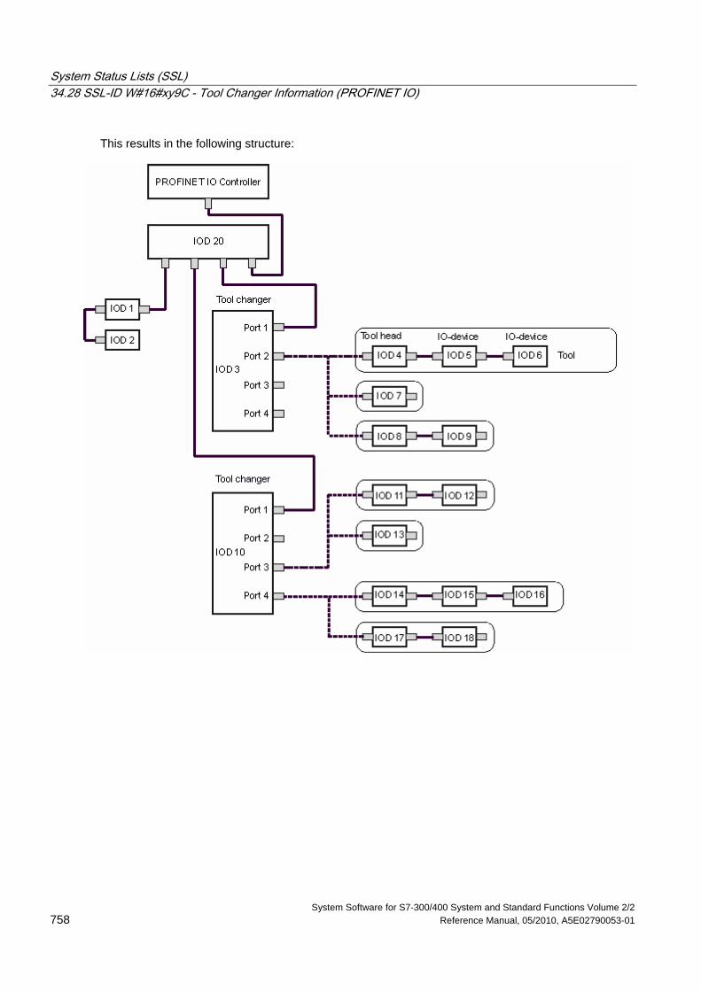
System Status Lists (SSL) 34.28 SSL-ID W#16#xy9C - Tool Changer Information (PROFINET IO)
System Software for S7-300/400 System and Standard Functions Volume 2/2 758 Reference Manual, 05/2010, A5E02790053-01
This results in the following structure:
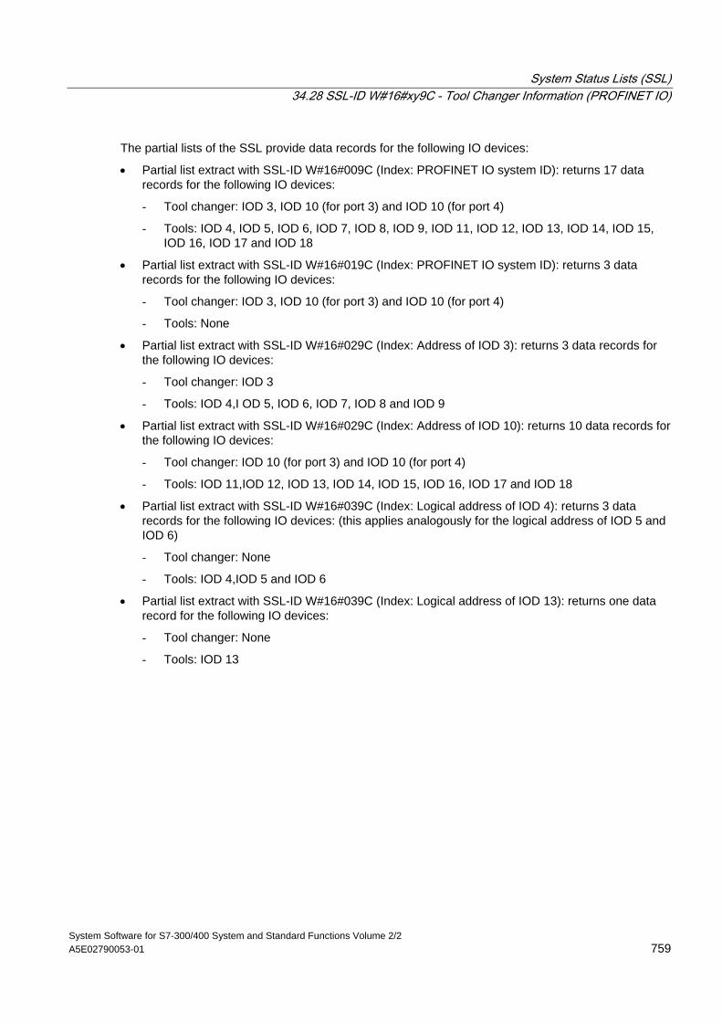
System Status Lists (SSL) 34.28 SSL-ID W#16#xy9C - Tool Changer Information (PROFINET IO)
System Software for S7-300/400 System and Standard Functions Volume 2/2 A5E02790053-01 759
The partial lists of the SSL provide data records for the following IO devices:
• Partial list extract with SSL-ID W#16#009C (Index: PROFINET IO system ID): returns 17 data records for the following IO devices:
- Tool changer: IOD 3, IOD 10 (for port 3) and IOD 10 (for port 4)
- Tools: IOD 4, IOD 5, IOD 6, IOD 7, IOD 8, IOD 9, IOD 11, IOD 12, IOD 13, IOD 14, IOD 15, IOD 16, IOD 17 and IOD 18
• Partial list extract with SSL-ID W#16#019C (Index: PROFINET IO system ID): returns 3 data records for the following IO devices:
- Tool changer: IOD 3, IOD 10 (for port 3) and IOD 10 (for port 4)
- Tools: None
• Partial list extract with SSL-ID W#16#029C (Index: Address of IOD 3): returns 3 data records for the following IO devices:
- Tool changer: IOD 3
- Tools: IOD 4,I OD 5, IOD 6, IOD 7, IOD 8 and IOD 9
• Partial list extract with SSL-ID W#16#029C (Index: Address of IOD 10): returns 10 data records for the following IO devices:
- Tool changer: IOD 10 (for port 3) and IOD 10 (for port 4)
- Tools: IOD 11,IOD 12, IOD 13, IOD 14, IOD 15, IOD 16, IOD 17 and IOD 18
• Partial list extract with SSL-ID W#16#039C (Index: Logical address of IOD 4): returns 3 data records for the following IO devices: (this applies analogously for the logical address of IOD 5 and IOD 6)
- Tool changer: None
- Tools: IOD 4,IOD 5 and IOD 6
• Partial list extract with SSL-ID W#16#039C (Index: Logical address of IOD 13): returns one data record for the following IO devices:
- Tool changer: None
- Tools: IOD 13
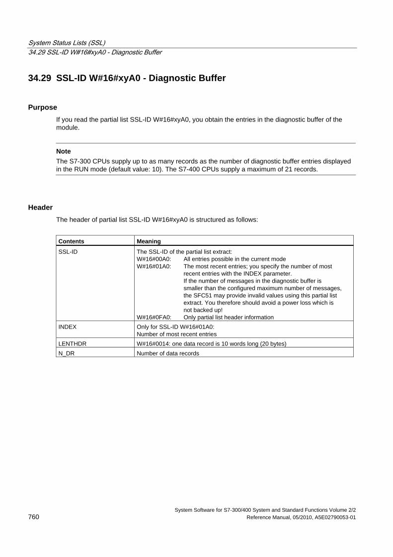
System Status Lists (SSL) 34.29 SSL-ID W#16#xyA0 - Diagnostic Buffer
System Software for S7-300/400 System and Standard Functions Volume 2/2 760 Reference Manual, 05/2010, A5E02790053-01
34.29 SSL-ID W#16#xyA0 - Diagnostic Buffer
Purpose If you read the partial list SSL-ID W#16#xyA0, you obtain the entries in the diagnostic buffer of the module.
Note
The S7-300 CPUs supply up to as many records as the number of diagnostic buffer entries displayed in the RUN mode (default value: 10). The S7-400 CPUs supply a maximum of 21 records.
Header The header of partial list SSL-ID W#16#xyA0 is structured as follows:
Contents Meaning
SSL-ID The SSL-ID of the partial list extract: W#16#00A0: All entries possible in the current mode W#16#01A0: The most recent entries; you specify the number of most recent entries with the INDEX parameter. If the number of messages in the diagnostic buffer is smaller than the configured maximum number of messages, the SFC51 may provide invalid values using this partial list extract. You therefore should avoid a power loss which is not backed up! W#16#0FA0: Only partial list header information
INDEX Only for SSL-ID W#16#01A0: Number of most recent entries
LENTHDR W#16#0014: one data record is 10 words long (20 bytes) N_DR Number of data records
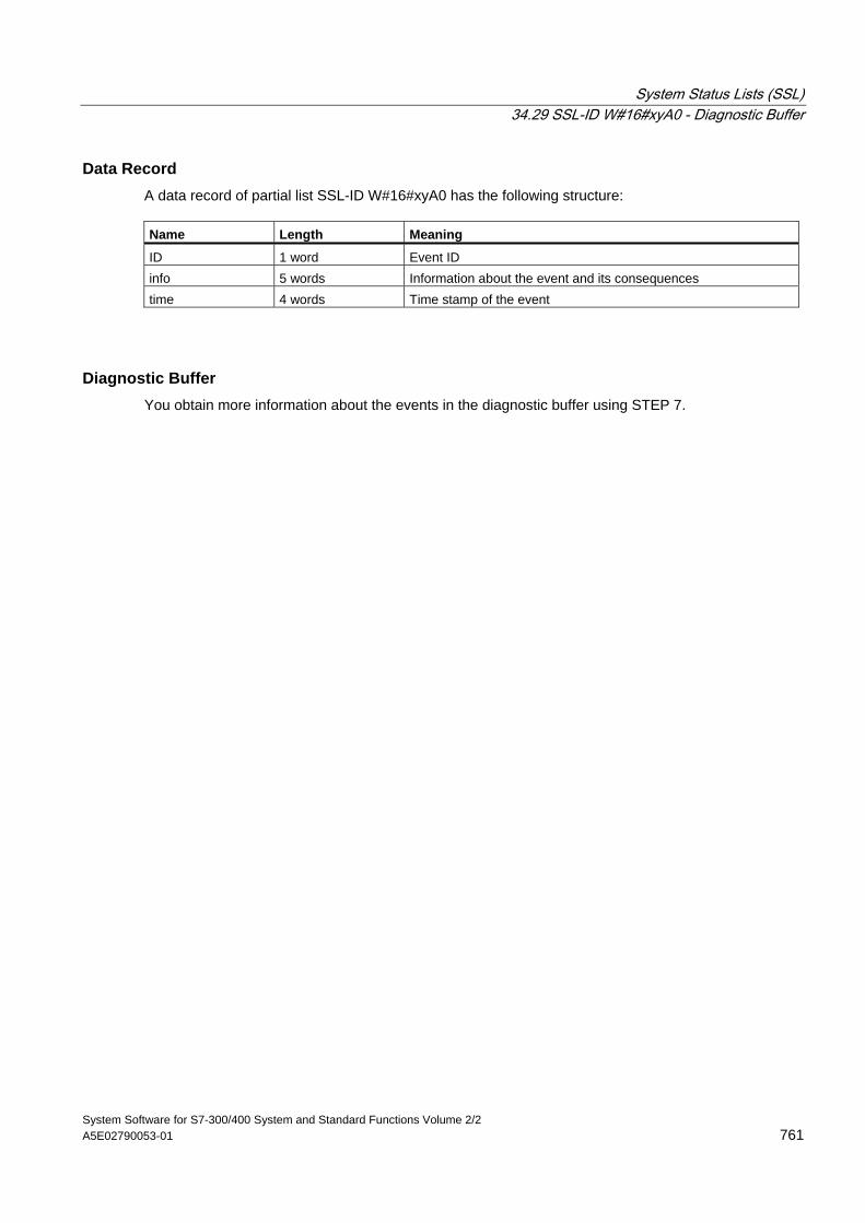
System Status Lists (SSL) 34.29 SSL-ID W#16#xyA0 - Diagnostic Buffer
System Software for S7-300/400 System and Standard Functions Volume 2/2 A5E02790053-01 761
Data Record A data record of partial list SSL-ID W#16#xyA0 has the following structure: Name Length Meaning
ID 1 word Event ID info 5 words Information about the event and its consequences time 4 words Time stamp of the event
Diagnostic Buffer You obtain more information about the events in the diagnostic buffer using STEP 7.
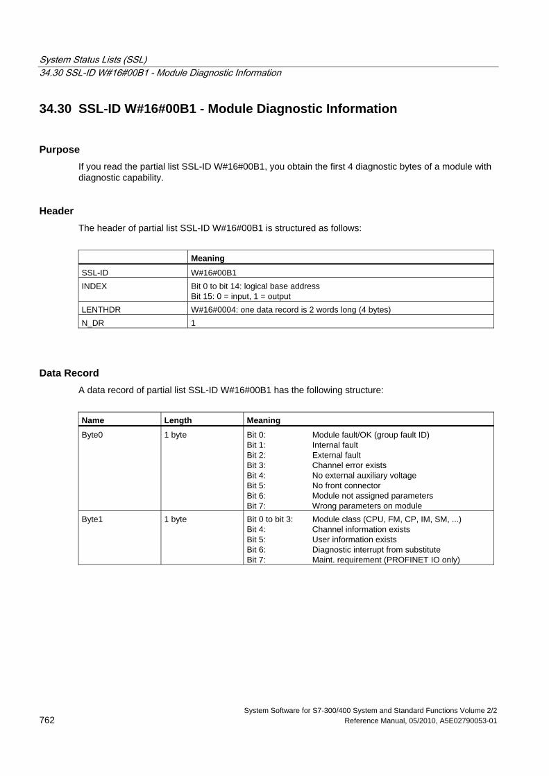
System Status Lists (SSL) 34.30 SSL-ID W#16#00B1 - Module Diagnostic Information
System Software for S7-300/400 System and Standard Functions Volume 2/2 762 Reference Manual, 05/2010, A5E02790053-01
34.30 SSL-ID W#16#00B1 - Module Diagnostic Information
Purpose If you read the partial list SSL-ID W#16#00B1, you obtain the first 4 diagnostic bytes of a module with diagnostic capability.
Header The header of partial list SSL-ID W#16#00B1 is structured as follows:
Meaning
SSL-ID W#16#00B1 INDEX Bit 0 to bit 14: logical base address
Bit 15: 0 = input, 1 = output LENTHDR W#16#0004: one data record is 2 words long (4 bytes) N_DR 1
Data Record A data record of partial list SSL-ID W#16#00B1 has the following structure:
Name Length Meaning
Byte0 1 byte Bit 0: Module fault/OK (group fault ID) Bit 1: Internal fault Bit 2: External fault Bit 3: Channel error exists Bit 4: No external auxiliary voltage Bit 5: No front connector Bit 6: Module not assigned parameters Bit 7: Wrong parameters on module
Byte1 1 byte Bit 0 to bit 3: Module class (CPU, FM, CP, IM, SM, ...) Bit 4: Channel information exists Bit 5: User information exists Bit 6: Diagnostic interrupt from substitute Bit 7: Maint. requirement (PROFINET IO only)
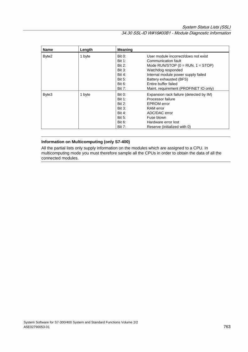
System Status Lists (SSL) 34.30 SSL-ID W#16#00B1 - Module Diagnostic Information
System Software for S7-300/400 System and Standard Functions Volume 2/2 A5E02790053-01 763
Name Length Meaning
Byte2 1 byte Bit 0: User module incorrect/does not exist Bit 1: Communication fault Bit 2: Mode RUN/STOP (0 = RUN, 1 = STOP) Bit 3: Watchdog responded Bit 4: Internal module power supply failed Bit 5: Battery exhausted (BFS) Bit 6: Entire buffer failed Bit 7: Maint. requirement (PROFINET IO only)
Byte3 1 byte Bit 0: Expansion rack failure (detected by IM) Bit 1: Processor failure Bit 2: EPROM error Bit 3: RAM error Bit 4: ADC/DAC error Bit 5: Fuse blown Bit 6: Hardware error lost Bit 7: Reserve (initialized with 0)
Information on Multicomputing (only S7-400)
All the partial lists only supply information on the modules which are assigned to a CPU. In multicomputing mode you must therefore sample all the CPUs in order to obtain the data of all the connected modules.
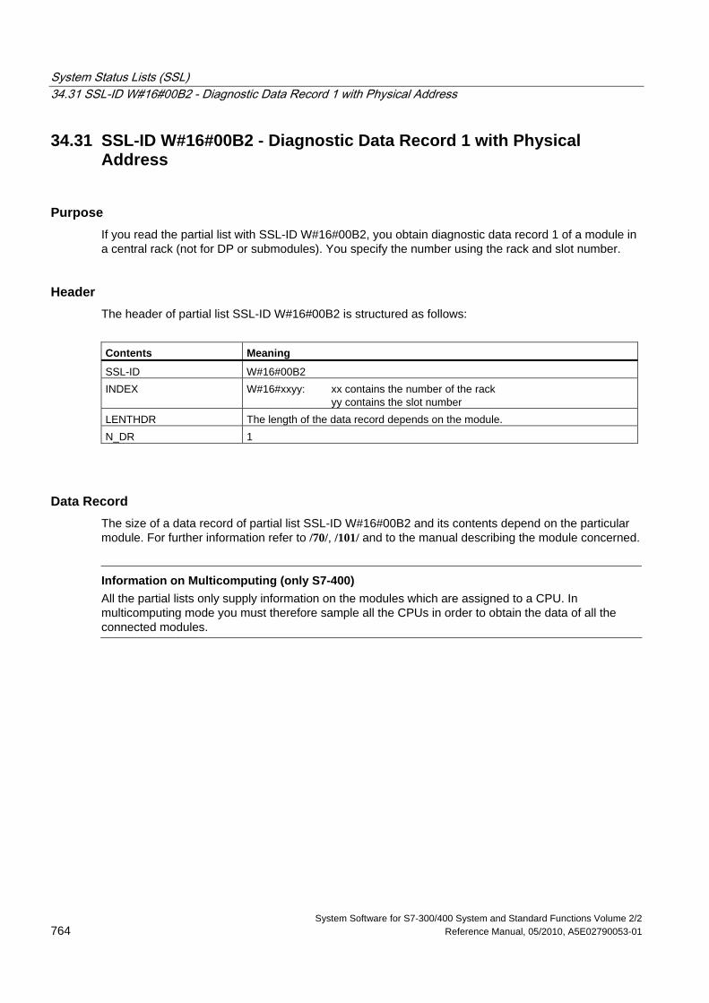
System Status Lists (SSL) 34.31 SSL-ID W#16#00B2 - Diagnostic Data Record 1 with Physical Address
System Software for S7-300/400 System and Standard Functions Volume 2/2 764 Reference Manual, 05/2010, A5E02790053-01
34.31 SSL-ID W#16#00B2 - Diagnostic Data Record 1 with Physical Address
Purpose If you read the partial list with SSL-ID W#16#00B2, you obtain diagnostic data record 1 of a module in a central rack (not for DP or submodules). You specify the number using the rack and slot number.
Header The header of partial list SSL-ID W#16#00B2 is structured as follows:
Contents Meaning
SSL-ID W#16#00B2 INDEX W#16#xxyy: xx contains the number of the rack
yy contains the slot number LENTHDR The length of the data record depends on the module. N_DR 1
Data Record The size of a data record of partial list SSL-ID W#16#00B2 and its contents depend on the particular module. For further information refer to /70/, /101/ and to the manual describing the module concerned.
Information on Multicomputing (only S7-400)
All the partial lists only supply information on the modules which are assigned to a CPU. In multicomputing mode you must therefore sample all the CPUs in order to obtain the data of all the connected modules.
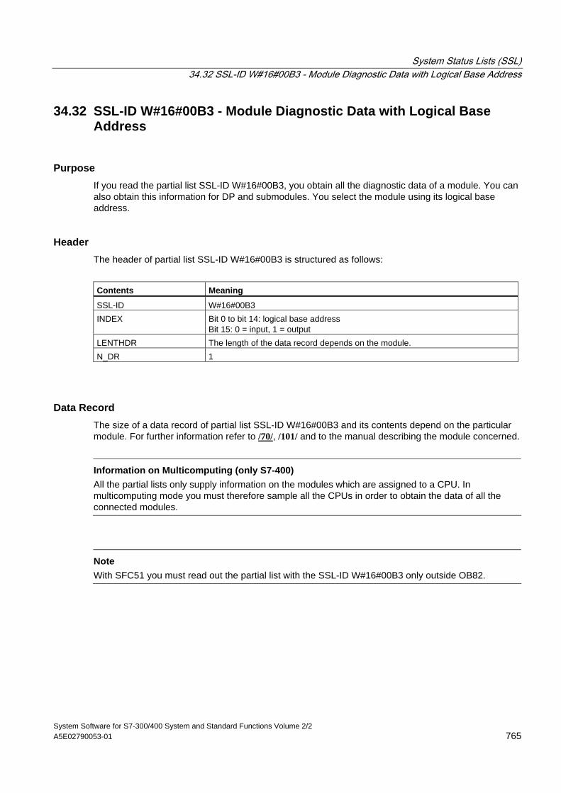
System Status Lists (SSL) 34.32 SSL-ID W#16#00B3 - Module Diagnostic Data with Logical Base Address
System Software for S7-300/400 System and Standard Functions Volume 2/2 A5E02790053-01 765
34.32 SSL-ID W#16#00B3 - Module Diagnostic Data with Logical Base Address
Purpose If you read the partial list SSL-ID W#16#00B3, you obtain all the diagnostic data of a module. You can also obtain this information for DP and submodules. You select the module using its logical base address.
Header The header of partial list SSL-ID W#16#00B3 is structured as follows:
Contents Meaning
SSL-ID W#16#00B3 INDEX Bit 0 to bit 14: logical base address
Bit 15: 0 = input, 1 = output LENTHDR The length of the data record depends on the module. N_DR 1
Data Record The size of a data record of partial list SSL-ID W#16#00B3 and its contents depend on the particular module. For further information refer to /70/, /101/ and to the manual describing the module concerned.
Information on Multicomputing (only S7-400)
All the partial lists only supply information on the modules which are assigned to a CPU. In multicomputing mode you must therefore sample all the CPUs in order to obtain the data of all the connected modules.
Note
With SFC51 you must read out the partial list with the SSL-ID W#16#00B3 only outside OB82.
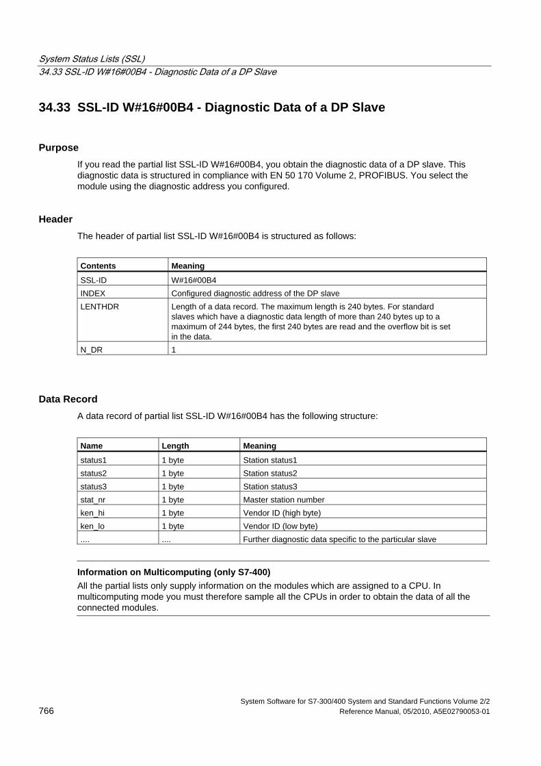
System Status Lists (SSL) 34.33 SSL-ID W#16#00B4 - Diagnostic Data of a DP Slave
System Software for S7-300/400 System and Standard Functions Volume 2/2 766 Reference Manual, 05/2010, A5E02790053-01
34.33 SSL-ID W#16#00B4 - Diagnostic Data of a DP Slave
Purpose If you read the partial list SSL-ID W#16#00B4, you obtain the diagnostic data of a DP slave. This diagnostic data is structured in compliance with EN 50 170 Volume 2, PROFIBUS. You select the module using the diagnostic address you configured.
Header The header of partial list SSL-ID W#16#00B4 is structured as follows:
Contents Meaning
SSL-ID W#16#00B4 INDEX Configured diagnostic address of the DP slave LENTHDR Length of a data record. The maximum length is 240 bytes. For standard
slaves which have a diagnostic data length of more than 240 bytes up to a maximum of 244 bytes, the first 240 bytes are read and the overflow bit is set in the data.
N_DR 1
Data Record A data record of partial list SSL-ID W#16#00B4 has the following structure:
Name Length Meaning
status1 1 byte Station status1 status2 1 byte Station status2 status3 1 byte Station status3 stat_nr 1 byte Master station number ken_hi 1 byte Vendor ID (high byte) ken_lo 1 byte Vendor ID (low byte) .... .... Further diagnostic data specific to the particular slave
Information on Multicomputing (only S7-400)
All the partial lists only supply information on the modules which are assigned to a CPU. In multicomputing mode you must therefore sample all the CPUs in order to obtain the data of all the connected modules.
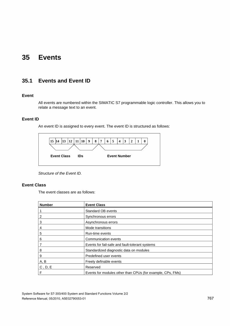
System Software for S7-300/400 System and Standard Functions Volume 2/2 Reference Manual, 05/2010, A5E02790053-01 767
35 Events
35.1 Events and Event ID
Event All events are numbered within the SIMATIC S7 programmable logic controller. This allows you to relate a message text to an event.
Event ID An event ID is assigned to every event. The event ID is structured as follows:
1214 1315 810 911 46 57 02 13
Event Class IDs Event Number
Structure of the Event ID.
Event Class The event classes are as follows:
Number Event Class
1 Standard OB events 2 Synchronous errors 3 Asynchronous errors 4 Mode transitions 5 Run-time events 6 Communication events 7 Events for fail-safe and fault-tolerant systems 8 Standardized diagnostic data on modules 9 Predefined user events A, B Freely definable events C , D, E Reserved F Events for modules other than CPUs (for example, CPs, FMs)
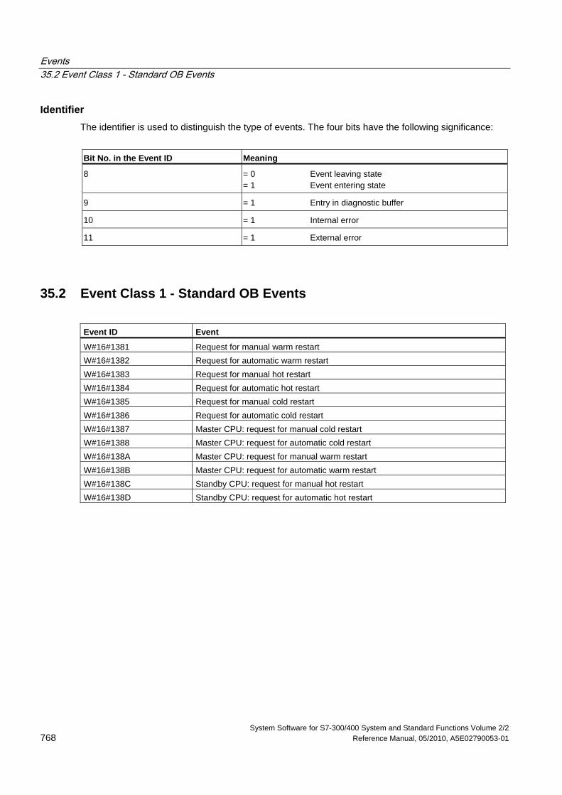
Events 35.2 Event Class 1 - Standard OB Events
System Software for S7-300/400 System and Standard Functions Volume 2/2 768 Reference Manual, 05/2010, A5E02790053-01
Identifier The identifier is used to distinguish the type of events. The four bits have the following significance:
Bit No. in the Event ID Meaning
8 = 0 Event leaving state = 1 Event entering state
9 = 1 Entry in diagnostic buffer
10 = 1 Internal error
11 = 1 External error
35.2 Event Class 1 - Standard OB Events
Event ID Event
W#16#1381 Request for manual warm restart W#16#1382 Request for automatic warm restart W#16#1383 Request for manual hot restart W#16#1384 Request for automatic hot restart W#16#1385 Request for manual cold restart W#16#1386 Request for automatic cold restart W#16#1387 Master CPU: request for manual cold restart W#16#1388 Master CPU: request for automatic cold restart W#16#138A Master CPU: request for manual warm restart W#16#138B Master CPU: request for automatic warm restart W#16#138C Standby CPU: request for manual hot restart W#16#138D Standby CPU: request for automatic hot restart
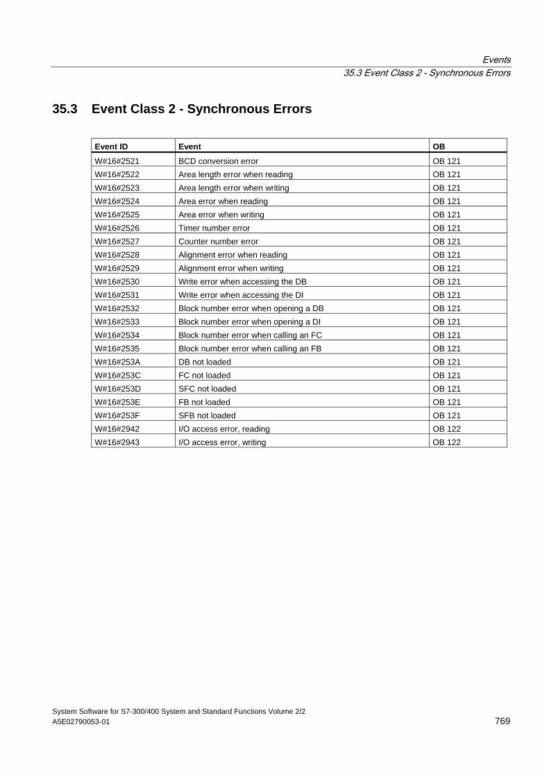
Events 35.3 Event Class 2 - Synchronous Errors
System Software for S7-300/400 System and Standard Functions Volume 2/2 A5E02790053-01 769
35.3 Event Class 2 - Synchronous Errors
Event ID Event OB
W#16#2521 BCD conversion error OB 121 W#16#2522 Area length error when reading OB 121 W#16#2523 Area length error when writing OB 121 W#16#2524 Area error when reading OB 121 W#16#2525 Area error when writing OB 121 W#16#2526 Timer number error OB 121 W#16#2527 Counter number error OB 121 W#16#2528 Alignment error when reading OB 121 W#16#2529 Alignment error when writing OB 121 W#16#2530 Write error when accessing the DB OB 121 W#16#2531 Write error when accessing the DI OB 121 W#16#2532 Block number error when opening a DB OB 121 W#16#2533 Block number error when opening a DI OB 121 W#16#2534 Block number error when calling an FC OB 121 W#16#2535 Block number error when calling an FB OB 121 W#16#253A DB not loaded OB 121 W#16#253C FC not loaded OB 121 W#16#253D SFC not loaded OB 121 W#16#253E FB not loaded OB 121 W#16#253F SFB not loaded OB 121 W#16#2942 I/O access error, reading OB 122 W#16#2943 I/O access error, writing OB 122
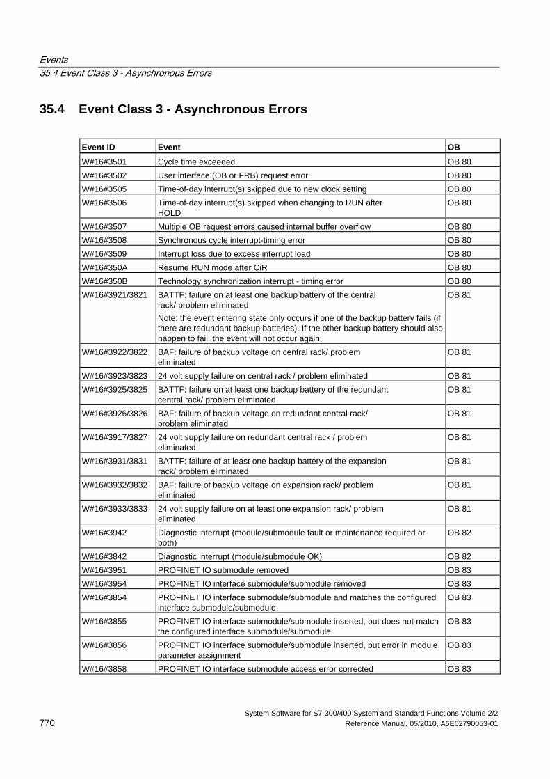
Events 35.4 Event Class 3 - Asynchronous Errors
System Software for S7-300/400 System and Standard Functions Volume 2/2 770 Reference Manual, 05/2010, A5E02790053-01
35.4 Event Class 3 - Asynchronous Errors
Event ID Event OB
W#16#3501 Cycle time exceeded. OB 80 W#16#3502 User interface (OB or FRB) request error OB 80 W#16#3505 Time-of-day interrupt(s) skipped due to new clock setting OB 80 W#16#3506 Time-of-day interrupt(s) skipped when changing to RUN after
HOLD OB 80
W#16#3507 Multiple OB request errors caused internal buffer overflow OB 80 W#16#3508 Synchronous cycle interrupt-timing error OB 80 W#16#3509 Interrupt loss due to excess interrupt load OB 80 W#16#350A Resume RUN mode after CiR OB 80 W#16#350B Technology synchronization interrupt - timing error OB 80 W#16#3921/3821 BATTF: failure on at least one backup battery of the central
rack/ problem eliminated Note: the event entering state only occurs if one of the backup battery fails (if there are redundant backup batteries). If the other backup battery should also happen to fail, the event will not occur again.
OB 81
W#16#3922/3822 BAF: failure of backup voltage on central rack/ problem eliminated
OB 81
W#16#3923/3823 24 volt supply failure on central rack / problem eliminated OB 81 W#16#3925/3825 BATTF: failure on at least one backup battery of the redundant
central rack/ problem eliminated OB 81
W#16#3926/3826 BAF: failure of backup voltage on redundant central rack/ problem eliminated
OB 81
W#16#3917/3827 24 volt supply failure on redundant central rack / problem eliminated
OB 81
W#16#3931/3831 BATTF: failure of at least one backup battery of the expansion rack/ problem eliminated
OB 81
W#16#3932/3832 BAF: failure of backup voltage on expansion rack/ problem eliminated
OB 81
W#16#3933/3833 24 volt supply failure on at least one expansion rack/ problem eliminated
OB 81
W#16#3942 Diagnostic interrupt (module/submodule fault or maintenance required or both)
OB 82
W#16#3842 Diagnostic interrupt (module/submodule OK) OB 82 W#16#3951 PROFINET IO submodule removed OB 83 W#16#3954 PROFINET IO interface submodule/submodule removed OB 83 W#16#3854 PROFINET IO interface submodule/submodule and matches the configured
interface submodule/submodule OB 83
W#16#3855 PROFINET IO interface submodule/submodule inserted, but does not match the configured interface submodule/submodule
OB 83
W#16#3856 PROFINET IO interface submodule/submodule inserted, but error in module parameter assignment
OB 83
W#16#3858 PROFINET IO interface submodule access error corrected OB 83
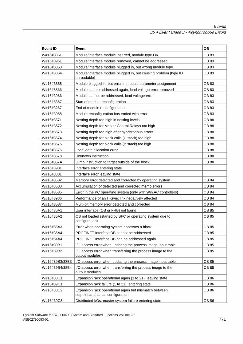
Events 35.4 Event Class 3 - Asynchronous Errors
System Software for S7-300/400 System and Standard Functions Volume 2/2 A5E02790053-01 771
Event ID Event OB
W#16#3861 Module/interface module inserted, module type OK OB 83 W#16#3961 Module/interface module removed, cannot be addressed OB 83 W#16#3863 Module/interface module plugged in, but wrong module type OB 83 W#16#3864 Module/interface module plugged in, but causing problem (type ID
unreadable) OB 83
W#16#3865 Module plugged in, but error in module parameter assignment OB 83 W#16#3866 Module can be addressed again, load voltage error removed OB 83 W#16#3966 Module cannot be addressed, load voltage error OB 83 W#16#3367 Start of module reconfiguration OB 83 W#16#3267 End of module reconfiguration OB 83 W#16#3968 Module reconfiguration has ended with error OB 83 W#16#3571 Nesting depth too high in nesting levels OB 88 W#16#3572 Nesting depth for Master Control Relays too high OB 88 W#16#3573 Nesting depth too high after synchronous errors OB 88 W#16#3574 Nesting depth for block calls (U stack) too high OB 88 W#16#3575 Nesting depth for block calls (B stack) too high OB 88 W#16#3576 Local data allocation error OB 88 W#16#3578 Unknown instruction OB 88 W#16#357A Jump instruction to target outside of the block OB 88 W#16#3981 Interface error entering state W#16#3881 Interface error leaving state W#16#3582 Memory error detected and corrected by operating system OB 84 W#16#3583 Accumulation of detected and corrected memo errors OB 84 W#16#3585 Error in the PC operating system (only with Win AC controllers) OB 84 W#16#3986 Performance of an H-Sync link negatively affected OB 84 W#16#3587 Multi-bit memory error detected and corrected OB 84 W#16#35A1 User interface (OB or FRB) not found OB 85 W#16#35A2 OB not loaded (started by SFC or operating system due to
configuration) OB 85
W#16#35A3 Error when operating system accesses a block OB 85 W#16#35A4 PROFINET Interface DB cannot be addressed OB 85 W#16#34A4 PROFINET Interface DB can be addressed again OB 85 W#16#39B1 I/O access error when updating the process image input table OB 85 W#16#39B2 I/O access error when transferring the process image to the
output modules OB 85
W#16#39B3/38B3 I/O access error when updating the process image input table OB 85 W#16#39B4/38B4 I/O access error when transferring the process image to the
output modules OB 85
W#16#38C1 Expansion rack operational again (1 to 21), leaving state OB 86 W#16#39C1 Expansion rack failure (1 to 21), entering state OB 86 W#16#38C2 Expansion rack operational again but mismatch between
setpoint and actual configuration OB 86
W#16#39C3 Distributed I/Os: master system failure entering state OB 86
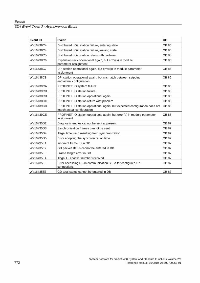
Events 35.4 Event Class 3 - Asynchronous Errors
System Software for S7-300/400 System and Standard Functions Volume 2/2 772 Reference Manual, 05/2010, A5E02790053-01
Event ID Event OB
W#16#39C4 Distributed I/Os: station failure, entering state OB 86 W#16#38C4 Distributed I/Os: station failure, leaving state OB 86 W#16#38C5 Distributed I/Os: station return with problem OB 86 W#16#38C6 Expansion rack operational again, but error(s) in module
parameter assignment OB 86
W#16#38C7 DP: station operational again, but error(s) in module parameter assignment
OB 86
W#16#38C8 DP: station operational again, but mismatch between setpoint and actual configuration
OB 86
W#16#39CA PROFINET IO system failure OB 86 W#16#39CB PROFINET IO station failure OB 86 W#16#38CB PROFINET IO station operational again OB 86 W#16#38CC PROFINET IO station return with problem OB 86 W#16#39CD PROFINET IO station operational again, but expected configuration does not
match actual configuration OB 86
W#16#39CE PROFINET IO station operational again, but error(s) in module parameter assignment
OB 86
W#16#35D2 Diagnostic entries cannot be sent at present OB 87 W#16#35D3 Synchronization frames cannot be sent OB 87 W#16#35D4 Illegal time jump resulting from synchronization OB 87 W#16#35D5 Error adopting the synchronization time OB 87 W#16#35E1 Incorrect frame ID in GD OB 87 W#16#35E2 GD packet status cannot be entered in DB OB 87 W#16#35E3 Frame length error in GD OB 87 W#16#35E4 Illegal GD packet number received OB 87 W#16#35E5 Error accessing DB in communication SFBs for configured S7
connections OB 87
W#16#35E6 GD total status cannot be entered in DB OB 87
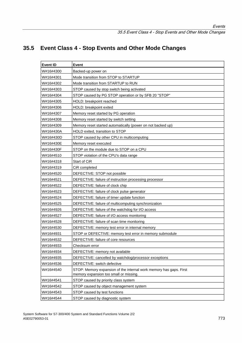
Events 35.5 Event Class 4 - Stop Events and Other Mode Changes
System Software for S7-300/400 System and Standard Functions Volume 2/2 A5E02790053-01 773
35.5 Event Class 4 - Stop Events and Other Mode Changes
Event ID Event
W#16#4300 Backed-up power on W#16#4301 Mode transition from STOP to STARTUP W#16#4302 Mode transition from STARTUP to RUN W#16#4303 STOP caused by stop switch being activated W#16#4304 STOP caused by PG STOP operation or by SFB 20 "STOP" W#16#4305 HOLD: breakpoint reached W#16#4306 HOLD: breakpoint exited W#16#4307 Memory reset started by PG operation W#16#4308 Memory reset started by switch setting W#16#4309 Memory reset started automatically (power on not backed up) W#16#430A HOLD exited, transition to STOP W#16#430D STOP caused by other CPU in multicomputing W#16#430E Memory reset executed W#16#430F STOP on the module due to STOP on a CPU W#16#4510 STOP violation of the CPU's data range W#16#4318 Start of CiR W#16#4319 CiR completed W#16#4520 DEFECTIVE: STOP not possible W#16#4521 DEFECTIVE: failure of instruction processing processor W#16#4522 DEFECTIVE: failure of clock chip W#16#4523 DEFECTIVE: failure of clock pulse generator W#16#4524 DEFECTIVE: failure of timer update function W#16#4525 DEFECTIVE: failure of multicomputing synchronization W#16#4926 DEFECTIVE: failure of the watchdog for I/O access W#16#4527 DEFECTIVE: failure of I/O access monitoring W#16#4528 DEFECTIVE: failure of scan time monitoring W#16#4530 DEFECTIVE: memory test error in internal memory W#16#4931 STOP or DEFECTIVE: memory test error in memory submodule W#16#4532 DEFECTIVE: failure of core resources W#16#4933 Checksum error W#16#4934 DEFECTIVE: memory not available W#16#4935 DEFECTIVE: cancelled by watchdog/processor exceptions W#16#4536 DEFECTIVE: switch defective W#16#4540 STOP: Memory expansion of the internal work memory has gaps. First
memory expansion too small or missing. W#16#4541 STOP caused by priority class system W#16#4542 STOP caused by object management system W#16#4543 STOP caused by test functions W#16#4544 STOP caused by diagnostic system
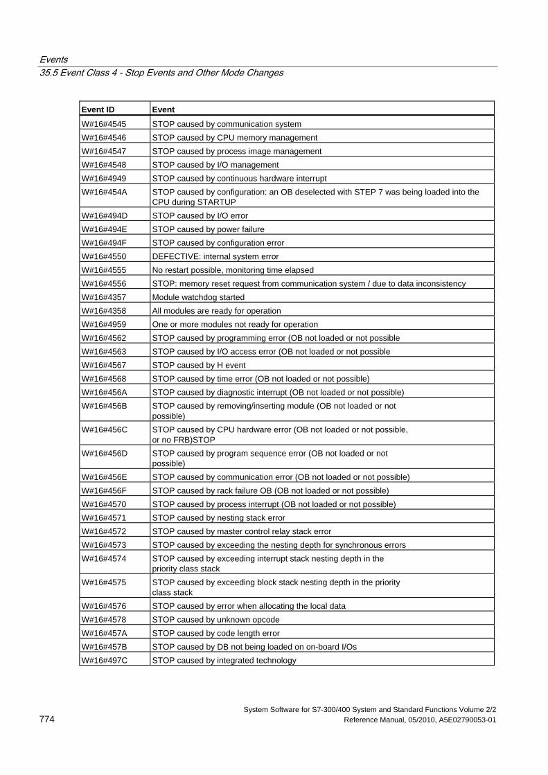
Events 35.5 Event Class 4 - Stop Events and Other Mode Changes
System Software for S7-300/400 System and Standard Functions Volume 2/2 774 Reference Manual, 05/2010, A5E02790053-01
Event ID Event
W#16#4545 STOP caused by communication system W#16#4546 STOP caused by CPU memory management W#16#4547 STOP caused by process image management W#16#4548 STOP caused by I/O management W#16#4949 STOP caused by continuous hardware interrupt W#16#454A STOP caused by configuration: an OB deselected with STEP 7 was being loaded into the
CPU during STARTUP W#16#494D STOP caused by I/O error W#16#494E STOP caused by power failure W#16#494F STOP caused by configuration error W#16#4550 DEFECTIVE: internal system error W#16#4555 No restart possible, monitoring time elapsed W#16#4556 STOP: memory reset request from communication system / due to data inconsistency W#16#4357 Module watchdog started W#16#4358 All modules are ready for operation W#16#4959 One or more modules not ready for operation W#16#4562 STOP caused by programming error (OB not loaded or not possible W#16#4563 STOP caused by I/O access error (OB not loaded or not possible W#16#4567 STOP caused by H event W#16#4568 STOP caused by time error (OB not loaded or not possible) W#16#456A STOP caused by diagnostic interrupt (OB not loaded or not possible) W#16#456B STOP caused by removing/inserting module (OB not loaded or not
possible) W#16#456C STOP caused by CPU hardware error (OB not loaded or not possible,
or no FRB)STOP W#16#456D STOP caused by program sequence error (OB not loaded or not
possible) W#16#456E STOP caused by communication error (OB not loaded or not possible) W#16#456F STOP caused by rack failure OB (OB not loaded or not possible) W#16#4570 STOP caused by process interrupt (OB not loaded or not possible) W#16#4571 STOP caused by nesting stack error W#16#4572 STOP caused by master control relay stack error W#16#4573 STOP caused by exceeding the nesting depth for synchronous errors W#16#4574 STOP caused by exceeding interrupt stack nesting depth in the
priority class stack W#16#4575 STOP caused by exceeding block stack nesting depth in the priority
class stack W#16#4576 STOP caused by error when allocating the local data W#16#4578 STOP caused by unknown opcode W#16#457A STOP caused by code length error W#16#457B STOP caused by DB not being loaded on on-board I/Os W#16#497C STOP caused by integrated technology
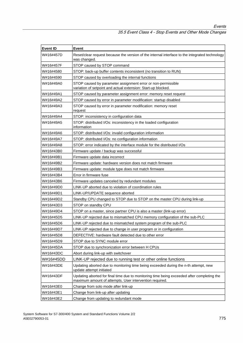
Events 35.5 Event Class 4 - Stop Events and Other Mode Changes
System Software for S7-300/400 System and Standard Functions Volume 2/2 A5E02790053-01 775
Event ID Event
W#16#457D Reset/clear request because the version of the internal interface to the integrated technology was changed.
W#16#457F STOP caused by STOP command W#16#4580 STOP: back-up buffer contents inconsistent (no transition to RUN) W#16#4590 STOP caused by overloading the internal functions W#16#49A0 STOP caused by parameter assignment error or non-permissible
variation of setpoint and actual extension: Start-up blocked. W#16#49A1 STOP caused by parameter assignment error: memory reset request W#16#49A2 STOP caused by error in parameter modification: startup disabled W#16#49A3 STOP caused by error in parameter modification: memory reset
request W#16#49A4 STOP: inconsistency in configuration data W#16#49A5 STOP: distributed I/Os: inconsistency in the loaded configuration
information W#16#49A6 STOP: distributed I/Os: invalid configuration information W#16#49A7 STOP: distributed I/Os: no configuration information W#16#49A8 STOP: error indicated by the interface module for the distributed I/Os W#16#43B0 Firmware update / backup was successful W#16#49B1 Firmware update data incorrect W#16#49B2 Firmware update: hardware version does not match firmware W#16#49B3 Firmware update: module type does not match firmware W#16#43B4 Error in firmware fuse W#16#43B6 Firmware updates canceled by redundant modules W#16#49D0 LINK-UP aborted due to violation of coordination rules W#16#49D1 LINK-UP/UPDATE sequence aborted W#16#49D2 Standby CPU changed to STOP due to STOP on the master CPU during link-up W#16#43D3 STOP on standby CPU W#16#49D4 STOP on a master, since partner CPU is also a master (link-up error) W#16#45D5 LINK-UP rejected due to mismatched CPU memory configuration of the sub-PLC W#16#45D6 LINK-UP rejected due to mismatched system program of the sub-PLC W#16#49D7 LINK-UP rejected due to change in user program or in configuration W#16#45D8 DEFECTIVE: hardware fault detected due to other error W#16#45D9 STOP due to SYNC module error W#16#45DA STOP due to synchronization error between H CPUs W#16#43DC Abort during link-up with switchover
W#16#45DD LINK-UP rejected due to running test or other online functions W#16#43DE Updating aborted due to monitoring time being exceeded during the n-th attempt, new
update attempt initiated W#16#43DF Updating aborted for final time due to monitoring time being exceeded after completing the
maximum amount of attempts. User intervention required. W#16#43E0 Change from solo mode after link-up W#16#43E1 Change from link-up after updating W#16#43E2 Change from updating to redundant mode
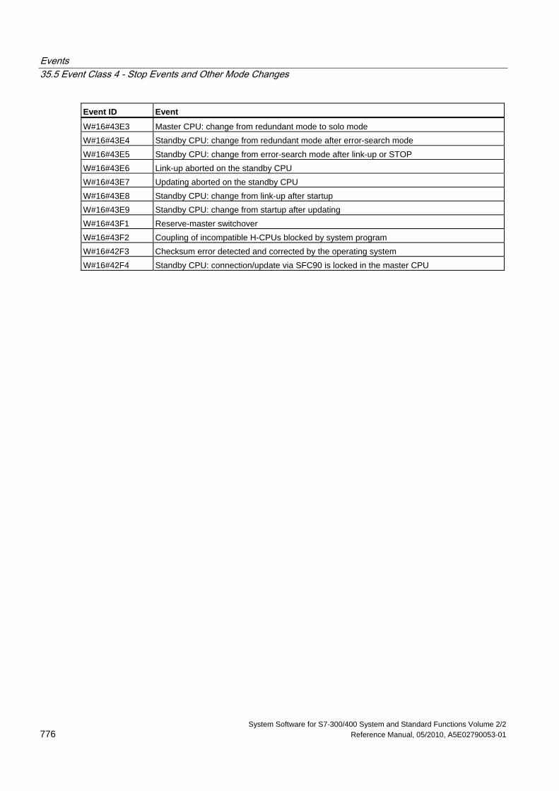
Events 35.5 Event Class 4 - Stop Events and Other Mode Changes
System Software for S7-300/400 System and Standard Functions Volume 2/2 776 Reference Manual, 05/2010, A5E02790053-01
Event ID Event
W#16#43E3 Master CPU: change from redundant mode to solo mode W#16#43E4 Standby CPU: change from redundant mode after error-search mode W#16#43E5 Standby CPU: change from error-search mode after link-up or STOP W#16#43E6 Link-up aborted on the standby CPU W#16#43E7 Updating aborted on the standby CPU W#16#43E8 Standby CPU: change from link-up after startup W#16#43E9 Standby CPU: change from startup after updating W#16#43F1 Reserve-master switchover W#16#43F2 Coupling of incompatible H-CPUs blocked by system program W#16#42F3 Checksum error detected and corrected by the operating system W#16#42F4 Standby CPU: connection/update via SFC90 is locked in the master CPU
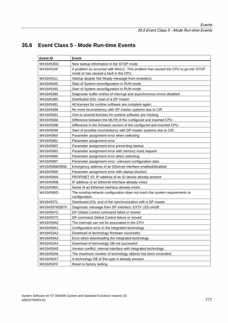
Events 35.6 Event Class 5 - Mode Run-time Events
System Software for S7-300/400 System and Standard Functions Volume 2/2 A5E02790053-01 777
35.6 Event Class 5 - Mode Run-time Events Event ID Event W#16#530D New startup information in the STOP mode W#16#510F A problem as occurred with WinLC. This problem has caused the CPU to go into STOP
mode or has caused a fault in the CPU. W#16#5311 Startup despite Not Ready message from module(s) W#16#5545 Start of System reconfiguration in RUN mode W#16#5445 Start of System reconfiguration in RUN mode W#16#5380 Diagnostic buffer entries of interrupt and asynchronous errors disabled W#16#5395 Distributed I/Os: reset of a DP master W#16#5481 All licenses for runtime software are complete again. W#16#5498 No more inconsistency with DP master systems due to CiR W#16#5581 One or several licenses for runtime software are missing. W#16#558A Difference between the MLFB of the configured and inserted CPU W#16#558B Difference in the firmware version of the configured and inserted CPU W#16#5598 Start of possible inconsistency with DP master systems due to CiR W#16#5960 Parameter assignment error when switching W#16#5961 Parameter assignment error W#16#5962 Parameter assignment error preventing startup W#16#5963 Parameter assignment error with memory reset request W#16#5966 Parameter assignment error when switching W#16#5967 Parameter assignment error: unknown configuration data W#16#5968/5858 Emergency address of an Ethernet interface enabled/disabled W#16#5969 Parameter assignment error with startup blocked W#16#596A PROFINET IO: IP address of an IO device already present W#16#596B IP address of an Ethernet interface already exists W#16#596C Name of an Ethernet interface already exists W#16#596D The existing network configuration does not mach the system requirements or
configuration. W#16#5371 Distributed I/Os: end of the synchronization with a DP master W#16#5979/5879 Diagnostic message from DP interface: EXTF LED on/off W#16#597C DP Global Control command failed or moved W#16#597C DP command Global Control failure or moved W#16#59A0 The interrupt can not be associated in the CPU W#16#59A1 Configuration error in the integrated technology W#16#53A2 Download of technology firmware successful W#16#59A3 Error when downloading the integrated technology W#16#53A4 Download of technology DB not successful W#16#55A5 Version conflict: internal interface with integrated technology W#16#55A6 The maximum number of technology objects has been exceeded. W#16#55A7 A technology DB of this type is already present. W#16#53FF Reset to factory setting
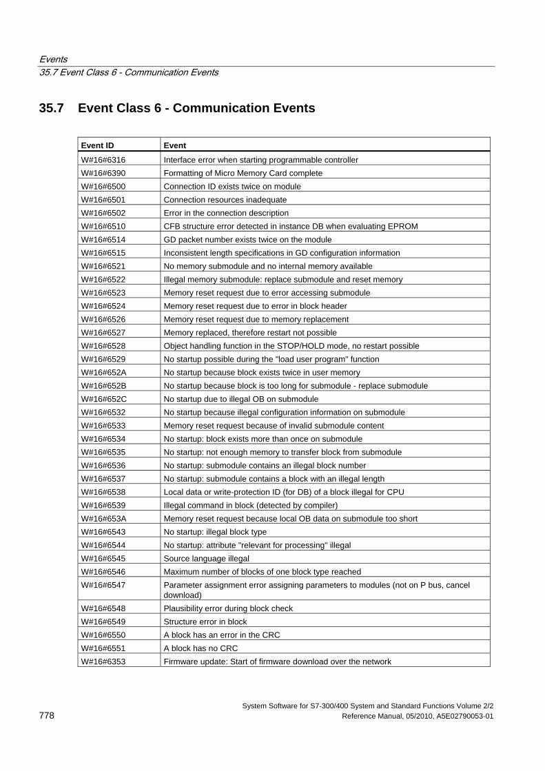
Events 35.7 Event Class 6 - Communication Events
System Software for S7-300/400 System and Standard Functions Volume 2/2 778 Reference Manual, 05/2010, A5E02790053-01
35.7 Event Class 6 - Communication Events
Event ID Event
W#16#6316 Interface error when starting programmable controller W#16#6390 Formatting of Micro Memory Card complete W#16#6500 Connection ID exists twice on module W#16#6501 Connection resources inadequate W#16#6502 Error in the connection description W#16#6510 CFB structure error detected in instance DB when evaluating EPROM W#16#6514 GD packet number exists twice on the module W#16#6515 Inconsistent length specifications in GD configuration information W#16#6521 No memory submodule and no internal memory available W#16#6522 Illegal memory submodule: replace submodule and reset memory W#16#6523 Memory reset request due to error accessing submodule W#16#6524 Memory reset request due to error in block header W#16#6526 Memory reset request due to memory replacement W#16#6527 Memory replaced, therefore restart not possible W#16#6528 Object handling function in the STOP/HOLD mode, no restart possible W#16#6529 No startup possible during the "load user program" function W#16#652A No startup because block exists twice in user memory W#16#652B No startup because block is too long for submodule - replace submodule W#16#652C No startup due to illegal OB on submodule W#16#6532 No startup because illegal configuration information on submodule W#16#6533 Memory reset request because of invalid submodule content W#16#6534 No startup: block exists more than once on submodule W#16#6535 No startup: not enough memory to transfer block from submodule W#16#6536 No startup: submodule contains an illegal block number W#16#6537 No startup: submodule contains a block with an illegal length W#16#6538 Local data or write-protection ID (for DB) of a block illegal for CPU W#16#6539 Illegal command in block (detected by compiler) W#16#653A Memory reset request because local OB data on submodule too short W#16#6543 No startup: illegal block type W#16#6544 No startup: attribute "relevant for processing" illegal W#16#6545 Source language illegal W#16#6546 Maximum number of blocks of one block type reached W#16#6547 Parameter assignment error assigning parameters to modules (not on P bus, cancel
download) W#16#6548 Plausibility error during block check W#16#6549 Structure error in block W#16#6550 A block has an error in the CRC W#16#6551 A block has no CRC W#16#6353 Firmware update: Start of firmware download over the network
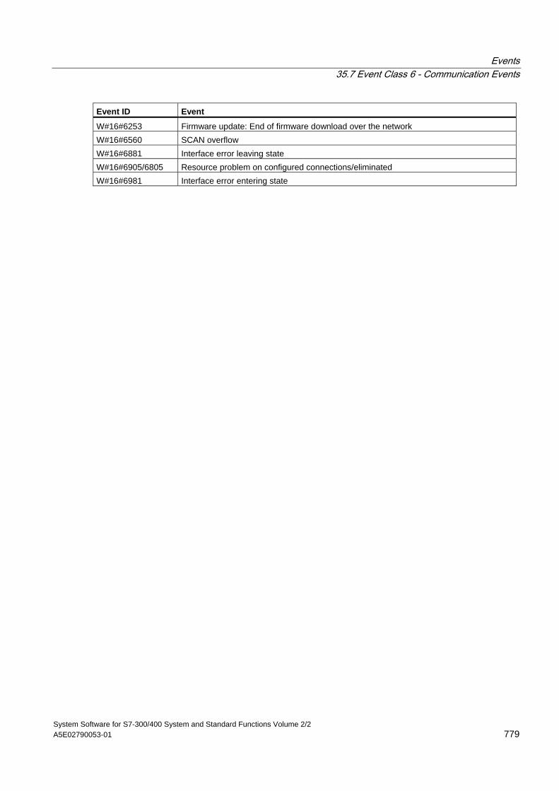
Events 35.7 Event Class 6 - Communication Events
System Software for S7-300/400 System and Standard Functions Volume 2/2 A5E02790053-01 779
Event ID Event
W#16#6253 Firmware update: End of firmware download over the network W#16#6560 SCAN overflow W#16#6881 Interface error leaving state W#16#6905/6805 Resource problem on configured connections/eliminated W#16#6981 Interface error entering state
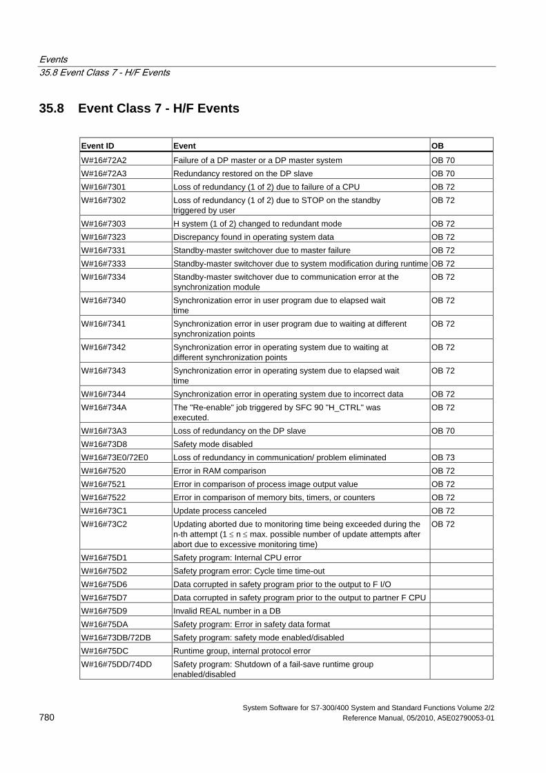
Events 35.8 Event Class 7 - H/F Events
System Software for S7-300/400 System and Standard Functions Volume 2/2 780 Reference Manual, 05/2010, A5E02790053-01
35.8 Event Class 7 - H/F Events
Event ID Event OB
W#16#72A2 Failure of a DP master or a DP master system OB 70 W#16#72A3 Redundancy restored on the DP slave OB 70 W#16#7301 Loss of redundancy (1 of 2) due to failure of a CPU OB 72 W#16#7302 Loss of redundancy (1 of 2) due to STOP on the standby
triggered by user OB 72
W#16#7303 H system (1 of 2) changed to redundant mode OB 72 W#16#7323 Discrepancy found in operating system data OB 72 W#16#7331 Standby-master switchover due to master failure OB 72 W#16#7333 Standby-master switchover due to system modification during runtime OB 72 W#16#7334 Standby-master switchover due to communication error at the
synchronization module OB 72
W#16#7340 Synchronization error in user program due to elapsed wait time
OB 72
W#16#7341 Synchronization error in user program due to waiting at different synchronization points
OB 72
W#16#7342 Synchronization error in operating system due to waiting at different synchronization points
OB 72
W#16#7343 Synchronization error in operating system due to elapsed wait time
OB 72
W#16#7344 Synchronization error in operating system due to incorrect data OB 72 W#16#734A The "Re-enable" job triggered by SFC 90 "H_CTRL" was
executed. OB 72
W#16#73A3 Loss of redundancy on the DP slave OB 70 W#16#73D8 Safety mode disabled W#16#73E0/72E0 Loss of redundancy in communication/ problem eliminated OB 73 W#16#7520 Error in RAM comparison OB 72 W#16#7521 Error in comparison of process image output value OB 72 W#16#7522 Error in comparison of memory bits, timers, or counters OB 72 W#16#73C1 Update process canceled OB 72 W#16#73C2 Updating aborted due to monitoring time being exceeded during the
n-th attempt (1 ≤ n ≤ max. possible number of update attempts after abort due to excessive monitoring time)
OB 72
W#16#75D1 Safety program: Internal CPU error W#16#75D2 Safety program error: Cycle time time-out W#16#75D6 Data corrupted in safety program prior to the output to F I/O W#16#75D7 Data corrupted in safety program prior to the output to partner F CPU W#16#75D9 Invalid REAL number in a DB W#16#75DA Safety program: Error in safety data format W#16#73DB/72DB Safety program: safety mode enabled/disabled W#16#75DC Runtime group, internal protocol error W#16#75DD/74DD Safety program: Shutdown of a fail-save runtime group
enabled/disabled
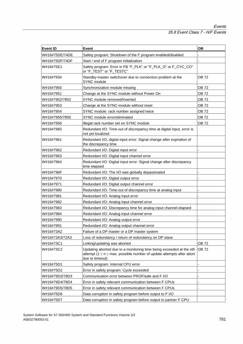
Events 35.8 Event Class 7 - H/F Events
System Software for S7-300/400 System and Standard Functions Volume 2/2 A5E02790053-01 781
Event ID Event OB
W#16#75DE/74DE Safety program: Shutdown of the F program enabled/disabled - W#16#75DF/74DF Start / end of F program initialization - W#16#75E1 Safety program: Error in FB "F_PLK" or "F_PLK_O" or F_CYC_CO"
or "F_TEST" or "F_TESTC"
W#16#7934 Standby-master switchover due to connection problem at the SYNC module
OB 72
W#16#7950 Synchronization module missing OB 72 W#16#7951 Change at the SYNC module without Power On OB 72 W#16#7952/7852 SYNC module removed/inserted OB 72 W#16#7953 Change at the SYNC-module without reset OB 72 W#16#7954 SYNC module: rack number assigned twice OB 72 W#16#7955/7855 SYNC module error/eliminated OB 72 W#16#7956 Illegal rack number set on SYNC module OB 72 W#16#7960 Redundant I/O: Time-out of discrepancy time at digital input, error is
not yet localized
W#16#7961 Redundant I/O, digital input error: Signal change after expiration of the discrepancy time
W#16#7962 Redundant I/O: Digital input error - W#16#7963 Redundant I/O: Digital input channel error W#16#7964 Redundant I/O: Digital input error: Signal change after discrepancy
time elapsed
W#16#796F Redundant I/O: The I/O was globally depassivated - W#16#7970 Redundant I/O: Digital output error - W#16#7971 Redundant I/O: Digital output channel error W#16#7980 Redundant I/O: Time-out of discrepancy time at analog input - W#16#7981 Redundant I/O: Analog input error - W#16#7982 Redundant I/O: Analog input channel error W#16#7983 Redundant I/O: Discrepancy time for analog input channel elapsed W#16#7984 Redundant I/O: Analog input channel error W#16#7990 Redundant I/O: Analog output error - W#16#7991 Redundant I/O: Analog output channel error W#16#73A2 Failure of a DP master or a DP master system W#16#73A3/72A3 Loss of redundancy / return of redundancy on DP slave W#16#73C1 Linking/updating was aborted OB 72 W#16#73C2 Updating aborted due to a monitoring time being exceeded at the nth
attempt (1 ≤ n ≤ max. possible number of update attempts after abort due to timeout)
OB 72
W#16#75D1 Safety program: Internal CPU error - W#16#75D2 Error in safety program: Cycle exceeded - W#16#79D3/78D3 Communication error between PROFIsafe and F I/O - W#16#79D4/78D4 Error in safety relevant communication between F CPUs - W#16#79D5/78D5 Error in safety relevant communication between F CPUs - W#16#75D6 Data corruption in safety program before output to F I/O W#16#75D7 Data corruption in safety program before output to partner F CPU
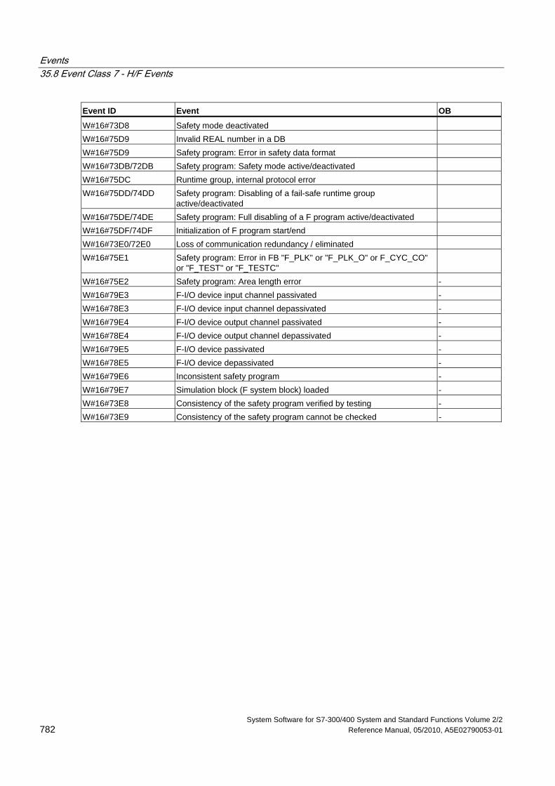
Events 35.8 Event Class 7 - H/F Events
System Software for S7-300/400 System and Standard Functions Volume 2/2 782 Reference Manual, 05/2010, A5E02790053-01
Event ID Event OB
W#16#73D8 Safety mode deactivated W#16#75D9 Invalid REAL number in a DB W#16#75D9 Safety program: Error in safety data format W#16#73DB/72DB Safety program: Safety mode active/deactivated W#16#75DC Runtime group, internal protocol error W#16#75DD/74DD Safety program: Disabling of a fail-safe runtime group
active/deactivated
W#16#75DE/74DE Safety program: Full disabling of a F program active/deactivated W#16#75DF/74DF Initialization of F program start/end W#16#73E0/72E0 Loss of communication redundancy / eliminated W#16#75E1 Safety program: Error in FB "F_PLK" or "F_PLK_O" or F_CYC_CO"
or "F_TEST" or "F_TESTC"
W#16#75E2 Safety program: Area length error - W#16#79E3 F-I/O device input channel passivated - W#16#78E3 F-I/O device input channel depassivated - W#16#79E4 F-I/O device output channel passivated - W#16#78E4 F-I/O device output channel depassivated - W#16#79E5 F-I/O device passivated - W#16#78E5 F-I/O device depassivated - W#16#79E6 Inconsistent safety program - W#16#79E7 Simulation block (F system block) loaded - W#16#73E8 Consistency of the safety program verified by testing - W#16#73E9 Consistency of the safety program cannot be checked -
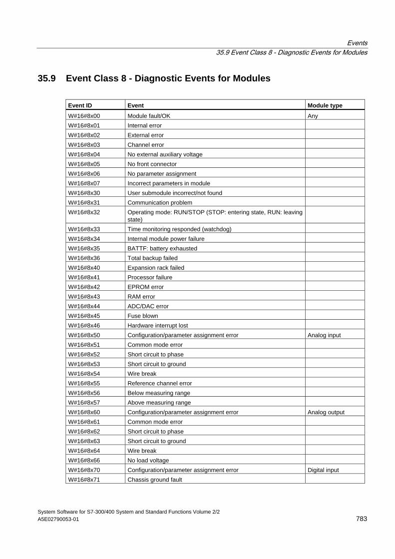
Events 35.9 Event Class 8 - Diagnostic Events for Modules
System Software for S7-300/400 System and Standard Functions Volume 2/2 A5E02790053-01 783
35.9 Event Class 8 - Diagnostic Events for Modules
Event ID Event Module type
W#16#8x00 Module fault/OK Any W#16#8x01 Internal error W#16#8x02 External error W#16#8x03 Channel error W#16#8x04 No external auxiliary voltage W#16#8x05 No front connector W#16#8x06 No parameter assignment W#16#8x07 Incorrect parameters in module W#16#8x30 User submodule incorrect/not found W#16#8x31 Communication problem W#16#8x32 Operating mode: RUN/STOP (STOP: entering state, RUN: leaving
state)
W#16#8x33 Time monitoring responded (watchdog) W#16#8x34 Internal module power failure W#16#8x35 BATTF: battery exhausted W#16#8x36 Total backup failed W#16#8x40 Expansion rack failed W#16#8x41 Processor failure W#16#8x42 EPROM error W#16#8x43 RAM error W#16#8x44 ADC/DAC error W#16#8x45 Fuse blown W#16#8x46 Hardware interrupt lost W#16#8x50 Configuration/parameter assignment error Analog input W#16#8x51 Common mode error W#16#8x52 Short circuit to phase W#16#8x53 Short circuit to ground W#16#8x54 Wire break W#16#8x55 Reference channel error W#16#8x56 Below measuring range W#16#8x57 Above measuring range W#16#8x60 Configuration/parameter assignment error Analog output W#16#8x61 Common mode error W#16#8x62 Short circuit to phase W#16#8x63 Short circuit to ground W#16#8x64 Wire break W#16#8x66 No load voltage W#16#8x70 Configuration/parameter assignment error Digital input W#16#8x71 Chassis ground fault
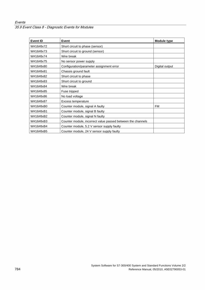
Events 35.9 Event Class 8 - Diagnostic Events for Modules
System Software for S7-300/400 System and Standard Functions Volume 2/2 784 Reference Manual, 05/2010, A5E02790053-01
Event ID Event Module type
W#16#8x72 Short circuit to phase (sensor) W#16#8x73 Short circuit to ground (sensor) W#16#8x74 Wire break W#16#8x75 No sensor power supply W#16#8x80 Configuration/parameter assignment error Digital output W#16#8x81 Chassis ground fault W#16#8x82 Short circuit to phase W#16#8x83 Short circuit to ground W#16#8x84 Wire break W#16#8x85 Fuse tripped W#16#8x86 No load voltage W#16#8x87 Excess temperature W#16#8xB0 Counter module, signal A faulty FM W#16#8xB1 Counter module, signal B faulty W#16#8xB2 Counter module, signal N faulty W#16#8xB3 Counter module, incorrect value passed between the channels W#16#8xB4 Counter module, 5.2 V sensor supply faulty W#16#8xB5 Counter module, 24 V sensor supply faulty
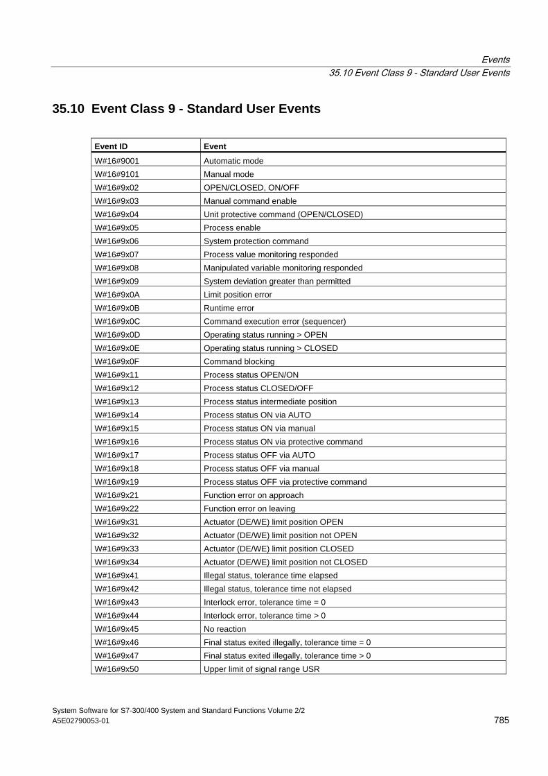
Events 35.10 Event Class 9 - Standard User Events
System Software for S7-300/400 System and Standard Functions Volume 2/2 A5E02790053-01 785
35.10 Event Class 9 - Standard User Events
Event ID Event
W#16#9001 Automatic mode W#16#9101 Manual mode W#16#9x02 OPEN/CLOSED, ON/OFF W#16#9x03 Manual command enable W#16#9x04 Unit protective command (OPEN/CLOSED) W#16#9x05 Process enable W#16#9x06 System protection command W#16#9x07 Process value monitoring responded W#16#9x08 Manipulated variable monitoring responded W#16#9x09 System deviation greater than permitted W#16#9x0A Limit position error W#16#9x0B Runtime error W#16#9x0C Command execution error (sequencer) W#16#9x0D Operating status running > OPEN W#16#9x0E Operating status running > CLOSED W#16#9x0F Command blocking W#16#9x11 Process status OPEN/ON W#16#9x12 Process status CLOSED/OFF W#16#9x13 Process status intermediate position W#16#9x14 Process status ON via AUTO W#16#9x15 Process status ON via manual W#16#9x16 Process status ON via protective command W#16#9x17 Process status OFF via AUTO W#16#9x18 Process status OFF via manual W#16#9x19 Process status OFF via protective command W#16#9x21 Function error on approach W#16#9x22 Function error on leaving W#16#9x31 Actuator (DE/WE) limit position OPEN W#16#9x32 Actuator (DE/WE) limit position not OPEN W#16#9x33 Actuator (DE/WE) limit position CLOSED W#16#9x34 Actuator (DE/WE) limit position not CLOSED W#16#9x41 Illegal status, tolerance time elapsed W#16#9x42 Illegal status, tolerance time not elapsed W#16#9x43 Interlock error, tolerance time = 0 W#16#9x44 Interlock error, tolerance time > 0 W#16#9x45 No reaction W#16#9x46 Final status exited illegally, tolerance time = 0 W#16#9x47 Final status exited illegally, tolerance time > 0 W#16#9x50 Upper limit of signal range USR
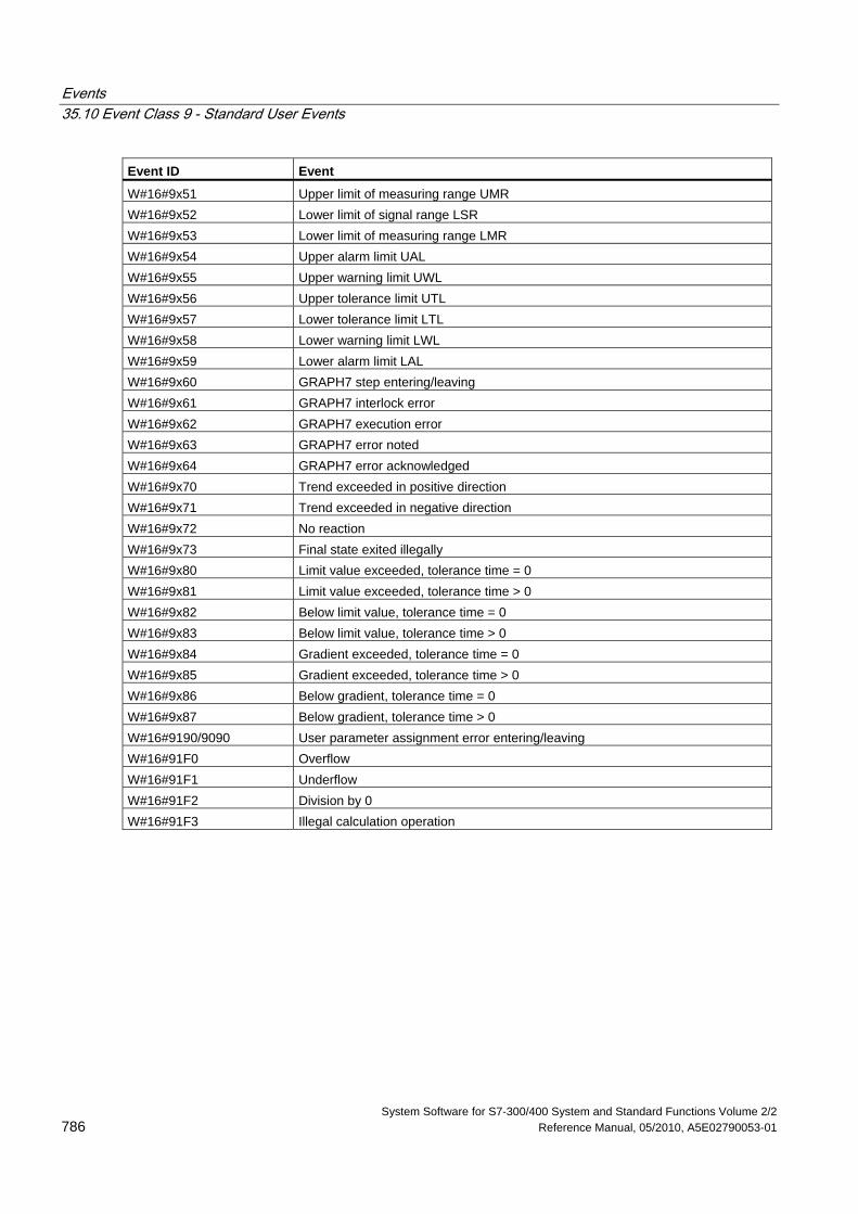
Events 35.10 Event Class 9 - Standard User Events
System Software for S7-300/400 System and Standard Functions Volume 2/2 786 Reference Manual, 05/2010, A5E02790053-01
Event ID Event
W#16#9x51 Upper limit of measuring range UMR W#16#9x52 Lower limit of signal range LSR W#16#9x53 Lower limit of measuring range LMR W#16#9x54 Upper alarm limit UAL W#16#9x55 Upper warning limit UWL W#16#9x56 Upper tolerance limit UTL W#16#9x57 Lower tolerance limit LTL W#16#9x58 Lower warning limit LWL W#16#9x59 Lower alarm limit LAL W#16#9x60 GRAPH7 step entering/leaving W#16#9x61 GRAPH7 interlock error W#16#9x62 GRAPH7 execution error W#16#9x63 GRAPH7 error noted W#16#9x64 GRAPH7 error acknowledged W#16#9x70 Trend exceeded in positive direction W#16#9x71 Trend exceeded in negative direction W#16#9x72 No reaction W#16#9x73 Final state exited illegally W#16#9x80 Limit value exceeded, tolerance time = 0 W#16#9x81 Limit value exceeded, tolerance time > 0 W#16#9x82 Below limit value, tolerance time = 0 W#16#9x83 Below limit value, tolerance time > 0 W#16#9x84 Gradient exceeded, tolerance time = 0 W#16#9x85 Gradient exceeded, tolerance time > 0 W#16#9x86 Below gradient, tolerance time = 0 W#16#9x87 Below gradient, tolerance time > 0 W#16#9190/9090 User parameter assignment error entering/leaving W#16#91F0 Overflow W#16#91F1 Underflow W#16#91F2 Division by 0 W#16#91F3 Illegal calculation operation
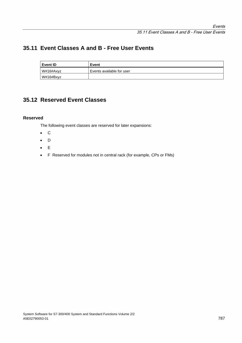
Events 35.11 Event Classes A and B - Free User Events
System Software for S7-300/400 System and Standard Functions Volume 2/2 A5E02790053-01 787
35.11 Event Classes A and B - Free User Events
Event ID Event
W#16#Axyz Events available for user W#16#Bxyz
35.12 Reserved Event Classes
Reserved The following event classes are reserved for later expansions:
• C
• D
• E
• F Reserved for modules not in central rack (for example, CPs or FMs)
Events 35.12 Reserved Event Classes
System Software for S7-300/400 System and Standard Functions Volume 2/2 788 Reference Manual, 05/2010, A5E02790053-01
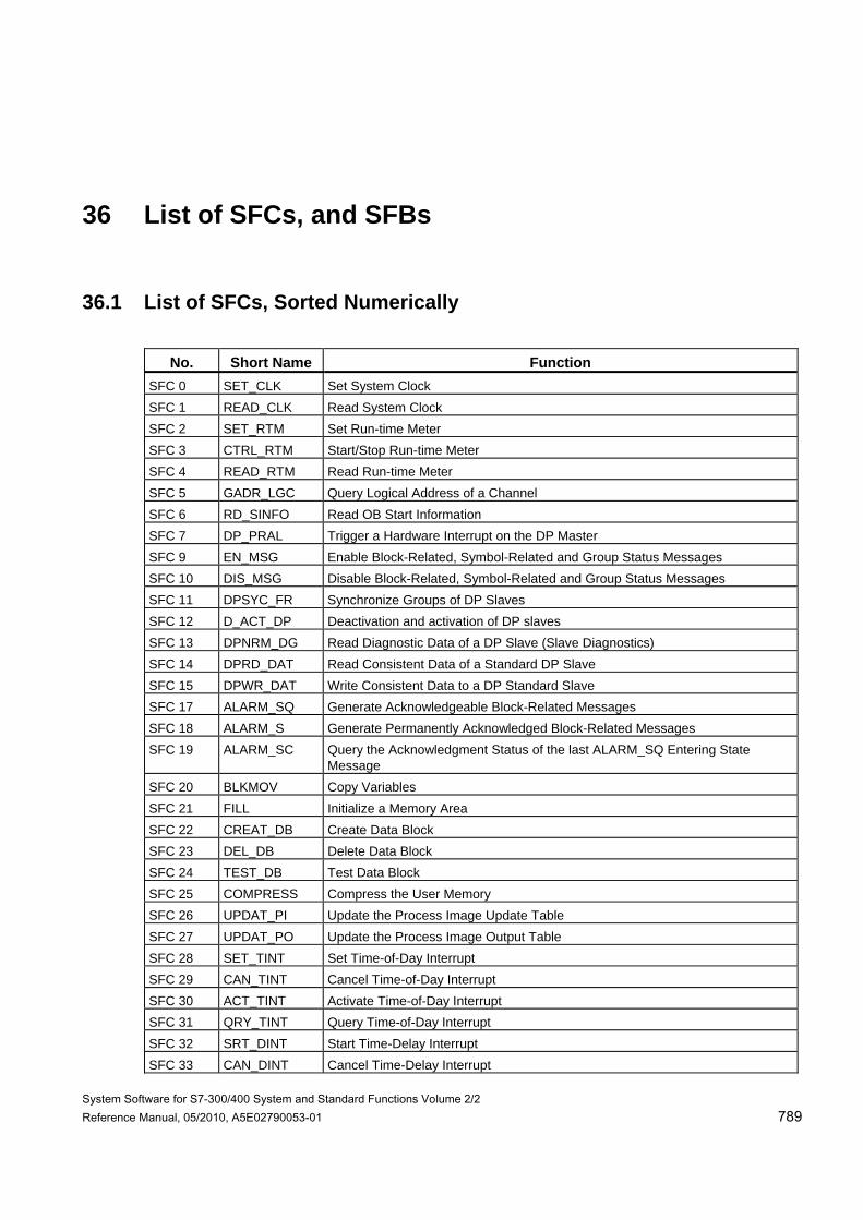
System Software for S7-300/400 System and Standard Functions Volume 2/2 Reference Manual, 05/2010, A5E02790053-01 789
36 List of SFCs, and SFBs
36.1 List of SFCs, Sorted Numerically
No. Short Name Function
SFC 0 SET_CLK Set System Clock SFC 1 READ_CLK Read System Clock SFC 2 SET_RTM Set Run-time Meter SFC 3 CTRL_RTM Start/Stop Run-time Meter SFC 4 READ_RTM Read Run-time Meter SFC 5 GADR_LGC Query Logical Address of a Channel SFC 6 RD_SINFO Read OB Start Information SFC 7 DP_PRAL Trigger a Hardware Interrupt on the DP Master SFC 9 EN_MSG Enable Block-Related, Symbol-Related and Group Status Messages SFC 10 DIS_MSG Disable Block-Related, Symbol-Related and Group Status Messages SFC 11 DPSYC_FR Synchronize Groups of DP Slaves SFC 12 D_ACT_DP Deactivation and activation of DP slaves SFC 13 DPNRM_DG Read Diagnostic Data of a DP Slave (Slave Diagnostics) SFC 14 DPRD_DAT Read Consistent Data of a Standard DP Slave SFC 15 DPWR_DAT Write Consistent Data to a DP Standard Slave SFC 17 ALARM_SQ Generate Acknowledgeable Block-Related Messages SFC 18 ALARM_S Generate Permanently Acknowledged Block-Related Messages SFC 19 ALARM_SC Query the Acknowledgment Status of the last ALARM_SQ Entering State
Message SFC 20 BLKMOV Copy Variables SFC 21 FILL Initialize a Memory Area SFC 22 CREAT_DB Create Data Block SFC 23 DEL_DB Delete Data Block SFC 24 TEST_DB Test Data Block SFC 25 COMPRESS Compress the User Memory SFC 26 UPDAT_PI Update the Process Image Update Table SFC 27 UPDAT_PO Update the Process Image Output Table SFC 28 SET_TINT Set Time-of-Day Interrupt SFC 29 CAN_TINT Cancel Time-of-Day Interrupt SFC 30 ACT_TINT Activate Time-of-Day Interrupt SFC 31 QRY_TINT Query Time-of-Day Interrupt SFC 32 SRT_DINT Start Time-Delay Interrupt SFC 33 CAN_DINT Cancel Time-Delay Interrupt
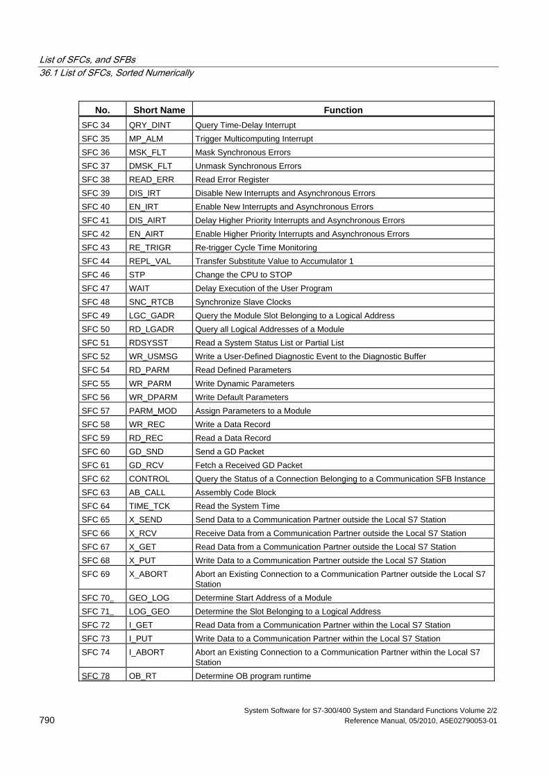
List of SFCs, and SFBs 36.1 List of SFCs, Sorted Numerically
System Software for S7-300/400 System and Standard Functions Volume 2/2 790 Reference Manual, 05/2010, A5E02790053-01
No. Short Name Function SFC 34 QRY_DINT Query Time-Delay Interrupt SFC 35 MP_ALM Trigger Multicomputing Interrupt SFC 36 MSK_FLT Mask Synchronous Errors SFC 37 DMSK_FLT Unmask Synchronous Errors SFC 38 READ_ERR Read Error Register SFC 39 DIS_IRT Disable New Interrupts and Asynchronous Errors SFC 40 EN_IRT Enable New Interrupts and Asynchronous Errors SFC 41 DIS_AIRT Delay Higher Priority Interrupts and Asynchronous Errors SFC 42 EN_AIRT Enable Higher Priority Interrupts and Asynchronous Errors SFC 43 RE_TRIGR Re-trigger Cycle Time Monitoring SFC 44 REPL_VAL Transfer Substitute Value to Accumulator 1 SFC 46 STP Change the CPU to STOP SFC 47 WAIT Delay Execution of the User Program SFC 48 SNC_RTCB Synchronize Slave Clocks SFC 49 LGC_GADR Query the Module Slot Belonging to a Logical Address SFC 50 RD_LGADR Query all Logical Addresses of a Module SFC 51 RDSYSST Read a System Status List or Partial List SFC 52 WR_USMSG Write a User-Defined Diagnostic Event to the Diagnostic Buffer SFC 54 RD_PARM Read Defined Parameters SFC 55 WR_PARM Write Dynamic Parameters SFC 56 WR_DPARM Write Default Parameters SFC 57 PARM_MOD Assign Parameters to a Module SFC 58 WR_REC Write a Data Record SFC 59 RD_REC Read a Data Record SFC 60 GD_SND Send a GD Packet SFC 61 GD_RCV Fetch a Received GD Packet SFC 62 CONTROL Query the Status of a Connection Belonging to a Communication SFB Instance SFC 63 AB_CALL Assembly Code Block SFC 64 TIME_TCK Read the System Time SFC 65 X_SEND Send Data to a Communication Partner outside the Local S7 Station SFC 66 X_RCV Receive Data from a Communication Partner outside the Local S7 Station SFC 67 X_GET Read Data from a Communication Partner outside the Local S7 Station SFC 68 X_PUT Write Data to a Communication Partner outside the Local S7 Station SFC 69 X_ABORT Abort an Existing Connection to a Communication Partner outside the Local S7
Station SFC 70 GEO_LOG Determine Start Address of a Module SFC 71 LOG_GEO Determine the Slot Belonging to a Logical Address SFC 72 I_GET Read Data from a Communication Partner within the Local S7 Station SFC 73 I_PUT Write Data to a Communication Partner within the Local S7 Station SFC 74 I_ABORT Abort an Existing Connection to a Communication Partner within the Local S7
Station SFC 78 OB_RT Determine OB program runtime
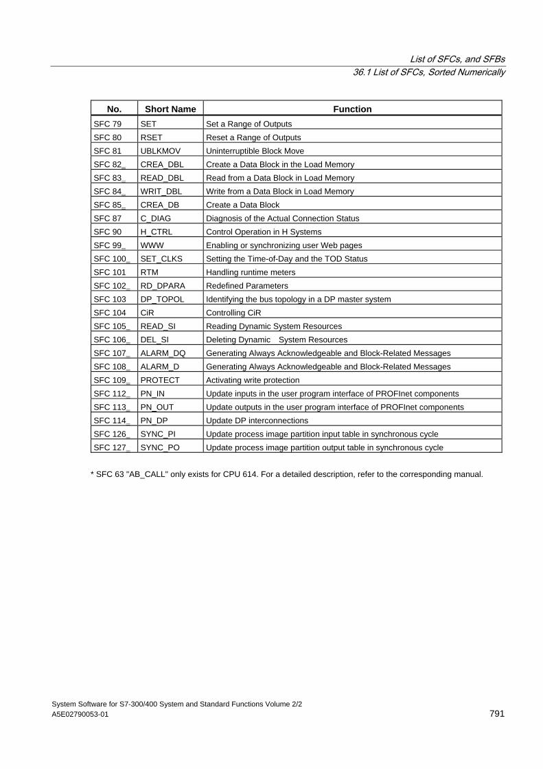
List of SFCs, and SFBs 36.1 List of SFCs, Sorted Numerically
System Software for S7-300/400 System and Standard Functions Volume 2/2 A5E02790053-01 791
No. Short Name Function SFC 79 SET Set a Range of Outputs SFC 80 RSET Reset a Range of Outputs SFC 81 UBLKMOV Uninterruptible Block Move SFC 82 CREA_DBL Create a Data Block in the Load Memory SFC 83 READ_DBL Read from a Data Block in Load Memory SFC 84 WRIT_DBL Write from a Data Block in Load Memory SFC 85 CREA_DB Create a Data Block SFC 87 C_DIAG Diagnosis of the Actual Connection Status SFC 90 H_CTRL Control Operation in H Systems SFC 99 WWW Enabling or synchronizing user Web pages SFC 100 SET_CLKS Setting the Time-of-Day and the TOD Status SFC 101 RTM Handling runtime meters SFC 102 RD_DPARA Redefined Parameters SFC 103 DP_TOPOL Identifying the bus topology in a DP master system SFC 104 CiR Controlling CiR SFC 105 READ_SI Reading Dynamic System Resources SFC 106 DEL_SI Deleting Dynamic System Resources SFC 107 ALARM_DQ Generating Always Acknowledgeable and Block-Related Messages SFC 108 ALARM_D Generating Always Acknowledgeable and Block-Related Messages SFC 109 PROTECT Activating write protection SFC 112 PN_IN Update inputs in the user program interface of PROFInet components SFC 113 PN_OUT Update outputs in the user program interface of PROFInet components SFC 114 PN_DP Update DP interconnections SFC 126 SYNC_PI Update process image partition input table in synchronous cycle SFC 127 SYNC_PO Update process image partition output table in synchronous cycle
* SFC 63 "AB_CALL" only exists for CPU 614. For a detailed description, refer to the corresponding manual.
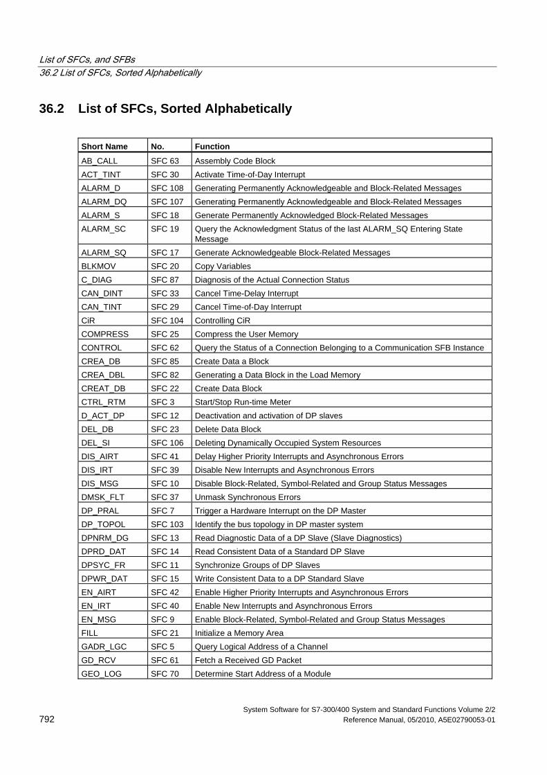
List of SFCs, and SFBs 36.2 List of SFCs, Sorted Alphabetically
System Software for S7-300/400 System and Standard Functions Volume 2/2 792 Reference Manual, 05/2010, A5E02790053-01
36.2 List of SFCs, Sorted Alphabetically
Short Name No. Function
AB_CALL SFC 63 Assembly Code Block ACT_TINT SFC 30 Activate Time-of-Day Interrupt ALARM_D SFC 108 Generating Permanently Acknowledgeable and Block-Related Messages ALARM_DQ SFC 107 Generating Permanently Acknowledgeable and Block-Related Messages ALARM_S SFC 18 Generate Permanently Acknowledged Block-Related Messages ALARM_SC SFC 19 Query the Acknowledgment Status of the last ALARM_SQ Entering State
Message ALARM_SQ SFC 17 Generate Acknowledgeable Block-Related Messages BLKMOV SFC 20 Copy Variables C_DIAG SFC 87 Diagnosis of the Actual Connection Status CAN_DINT SFC 33 Cancel Time-Delay Interrupt CAN_TINT SFC 29 Cancel Time-of-Day Interrupt CiR SFC 104 Controlling CiR COMPRESS SFC 25 Compress the User Memory CONTROL SFC 62 Query the Status of a Connection Belonging to a Communication SFB Instance CREA_DB SFC 85 Create Data a Block CREA_DBL SFC 82 Generating a Data Block in the Load Memory CREAT_DB SFC 22 Create Data Block CTRL_RTM SFC 3 Start/Stop Run-time Meter D_ACT_DP SFC 12 Deactivation and activation of DP slaves DEL_DB SFC 23 Delete Data Block DEL_SI SFC 106 Deleting Dynamically Occupied System Resources DIS_AIRT SFC 41 Delay Higher Priority Interrupts and Asynchronous Errors DIS_IRT SFC 39 Disable New Interrupts and Asynchronous Errors DIS_MSG SFC 10 Disable Block-Related, Symbol-Related and Group Status Messages DMSK_FLT SFC 37 Unmask Synchronous Errors DP_PRAL SFC 7 Trigger a Hardware Interrupt on the DP Master DP_TOPOL SFC 103 Identify the bus topology in DP master system DPNRM_DG SFC 13 Read Diagnostic Data of a DP Slave (Slave Diagnostics) DPRD_DAT SFC 14 Read Consistent Data of a Standard DP Slave DPSYC_FR SFC 11 Synchronize Groups of DP Slaves DPWR_DAT SFC 15 Write Consistent Data to a DP Standard Slave EN_AIRT SFC 42 Enable Higher Priority Interrupts and Asynchronous Errors EN_IRT SFC 40 Enable New Interrupts and Asynchronous Errors EN_MSG SFC 9 Enable Block-Related, Symbol-Related and Group Status Messages FILL SFC 21 Initialize a Memory Area GADR_LGC SFC 5 Query Logical Address of a Channel GD_RCV SFC 61 Fetch a Received GD Packet GEO_LOG SFC 70 Determine Start Address of a Module
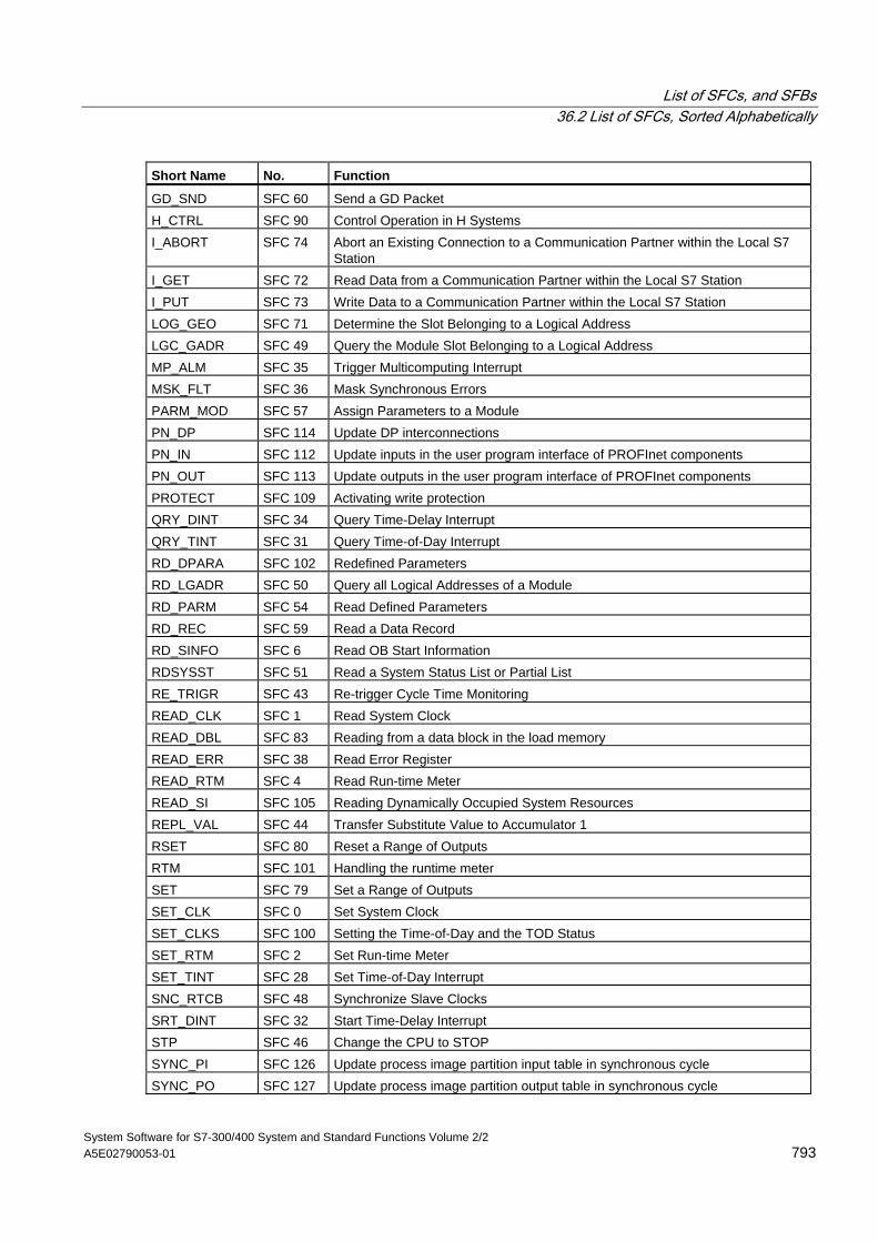
List of SFCs, and SFBs 36.2 List of SFCs, Sorted Alphabetically
System Software for S7-300/400 System and Standard Functions Volume 2/2 A5E02790053-01 793
Short Name No. Function
GD_SND SFC 60 Send a GD Packet H_CTRL SFC 90 Control Operation in H Systems I_ABORT SFC 74 Abort an Existing Connection to a Communication Partner within the Local S7
Station I_GET SFC 72 Read Data from a Communication Partner within the Local S7 Station I_PUT SFC 73 Write Data to a Communication Partner within the Local S7 Station LOG_GEO SFC 71 Determine the Slot Belonging to a Logical Address LGC_GADR SFC 49 Query the Module Slot Belonging to a Logical Address MP_ALM SFC 35 Trigger Multicomputing Interrupt MSK_FLT SFC 36 Mask Synchronous Errors PARM_MOD SFC 57 Assign Parameters to a Module PN_DP SFC 114 Update DP interconnections PN_IN SFC 112 Update inputs in the user program interface of PROFInet components PN_OUT SFC 113 Update outputs in the user program interface of PROFInet components PROTECT SFC 109 Activating write protection QRY_DINT SFC 34 Query Time-Delay Interrupt QRY_TINT SFC 31 Query Time-of-Day Interrupt RD_DPARA SFC 102 Redefined Parameters RD_LGADR SFC 50 Query all Logical Addresses of a Module RD_PARM SFC 54 Read Defined Parameters RD_REC SFC 59 Read a Data Record RD_SINFO SFC 6 Read OB Start Information RDSYSST SFC 51 Read a System Status List or Partial List RE_TRIGR SFC 43 Re-trigger Cycle Time Monitoring READ_CLK SFC 1 Read System Clock READ_DBL SFC 83 Reading from a data block in the load memory READ_ERR SFC 38 Read Error Register READ_RTM SFC 4 Read Run-time Meter READ_SI SFC 105 Reading Dynamically Occupied System Resources REPL_VAL SFC 44 Transfer Substitute Value to Accumulator 1 RSET SFC 80 Reset a Range of Outputs RTM SFC 101 Handling the runtime meter SET SFC 79 Set a Range of Outputs SET_CLK SFC 0 Set System Clock SET_CLKS SFC 100 Setting the Time-of-Day and the TOD Status SET_RTM SFC 2 Set Run-time Meter SET_TINT SFC 28 Set Time-of-Day Interrupt SNC_RTCB SFC 48 Synchronize Slave Clocks SRT_DINT SFC 32 Start Time-Delay Interrupt STP SFC 46 Change the CPU to STOP SYNC_PI SFC 126 Update process image partition input table in synchronous cycle SYNC_PO SFC 127 Update process image partition output table in synchronous cycle
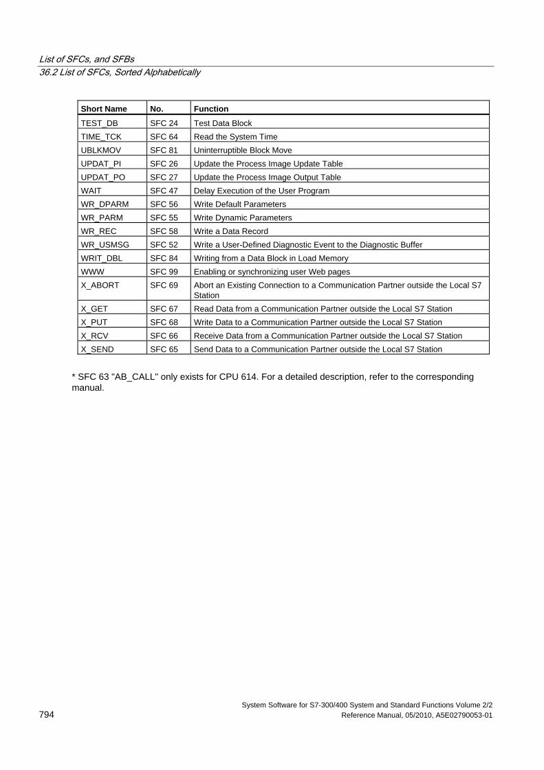
List of SFCs, and SFBs 36.2 List of SFCs, Sorted Alphabetically
System Software for S7-300/400 System and Standard Functions Volume 2/2 794 Reference Manual, 05/2010, A5E02790053-01
Short Name No. Function
TEST_DB SFC 24 Test Data Block TIME_TCK SFC 64 Read the System Time UBLKMOV SFC 81 Uninterruptible Block Move UPDAT_PI SFC 26 Update the Process Image Update Table UPDAT_PO SFC 27 Update the Process Image Output Table WAIT SFC 47 Delay Execution of the User Program WR_DPARM SFC 56 Write Default Parameters WR_PARM SFC 55 Write Dynamic Parameters WR_REC SFC 58 Write a Data Record WR_USMSG SFC 52 Write a User-Defined Diagnostic Event to the Diagnostic Buffer WRIT_DBL SFC 84 Writing from a Data Block in Load Memory WWW SFC 99 Enabling or synchronizing user Web pages X_ABORT SFC 69 Abort an Existing Connection to a Communication Partner outside the Local S7
Station X_GET SFC 67 Read Data from a Communication Partner outside the Local S7 Station X_PUT SFC 68 Write Data to a Communication Partner outside the Local S7 Station X_RCV SFC 66 Receive Data from a Communication Partner outside the Local S7 Station X_SEND SFC 65 Send Data to a Communication Partner outside the Local S7 Station
* SFC 63 "AB_CALL" only exists for CPU 614. For a detailed description, refer to the corresponding manual.
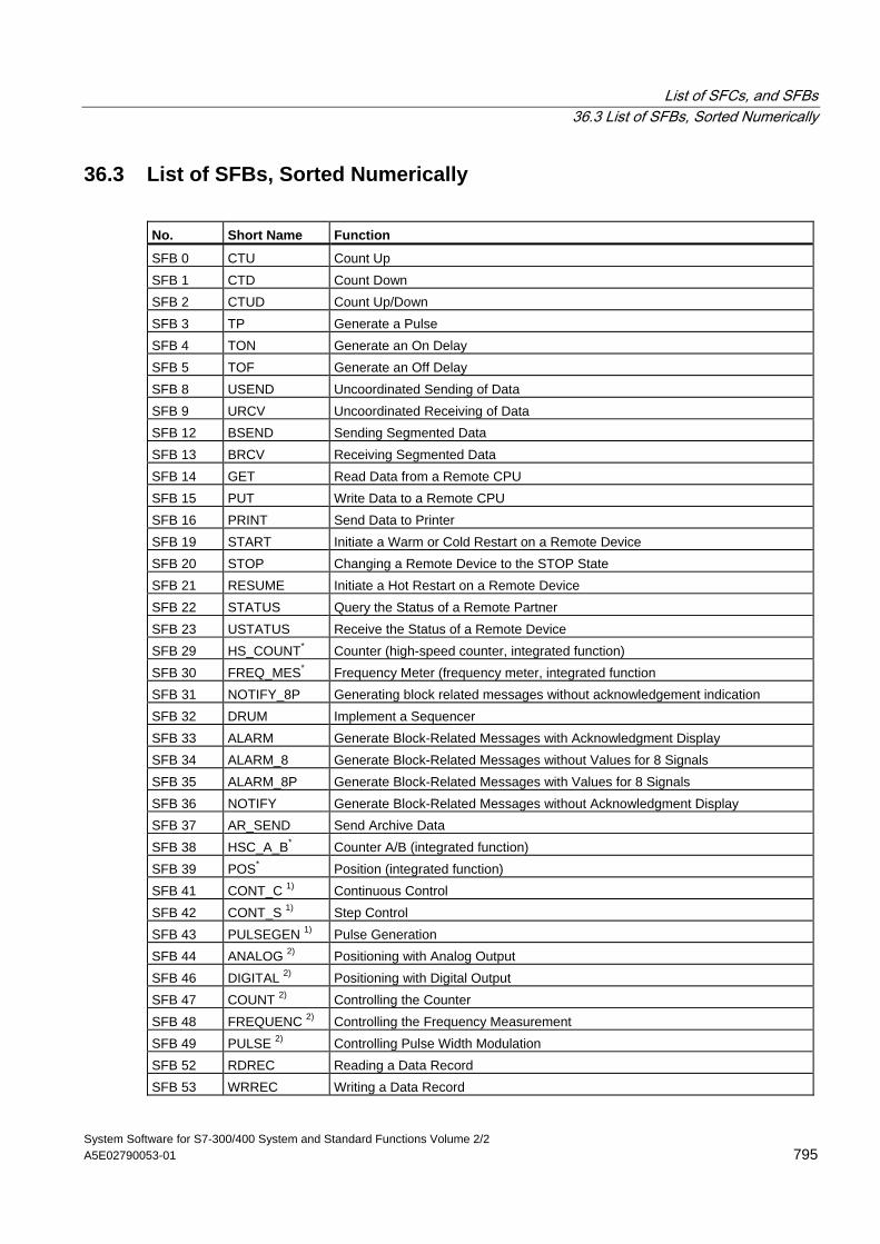
List of SFCs, and SFBs 36.3 List of SFBs, Sorted Numerically
System Software for S7-300/400 System and Standard Functions Volume 2/2 A5E02790053-01 795
36.3 List of SFBs, Sorted Numerically
No. Short Name Function
SFB 0 CTU Count Up SFB 1 CTD Count Down SFB 2 CTUD Count Up/Down SFB 3 TP Generate a Pulse SFB 4 TON Generate an On Delay SFB 5 TOF Generate an Off Delay SFB 8 USEND Uncoordinated Sending of Data SFB 9 URCV Uncoordinated Receiving of Data SFB 12 BSEND Sending Segmented Data SFB 13 BRCV Receiving Segmented Data SFB 14 GET Read Data from a Remote CPU SFB 15 PUT Write Data to a Remote CPU SFB 16 PRINT Send Data to Printer SFB 19 START Initiate a Warm or Cold Restart on a Remote Device SFB 20 STOP Changing a Remote Device to the STOP State SFB 21 RESUME Initiate a Hot Restart on a Remote Device SFB 22 STATUS Query the Status of a Remote Partner SFB 23 USTATUS Receive the Status of a Remote Device SFB 29 HS_COUNT* Counter (high-speed counter, integrated function) SFB 30 FREQ_MES* Frequency Meter (frequency meter, integrated function SFB 31 NOTIFY_8P Generating block related messages without acknowledgement indication SFB 32 DRUM Implement a Sequencer SFB 33 ALARM Generate Block-Related Messages with Acknowledgment Display SFB 34 ALARM_8 Generate Block-Related Messages without Values for 8 Signals SFB 35 ALARM_8P Generate Block-Related Messages with Values for 8 Signals SFB 36 NOTIFY Generate Block-Related Messages without Acknowledgment Display SFB 37 AR_SEND Send Archive Data SFB 38 HSC_A_B* Counter A/B (integrated function) SFB 39 POS* Position (integrated function) SFB 41 CONT_C 1) Continuous Control SFB 42 CONT_S 1) Step Control SFB 43 PULSEGEN 1) Pulse Generation SFB 44 ANALOG 2) Positioning with Analog Output SFB 46 DIGITAL 2) Positioning with Digital Output SFB 47 COUNT 2) Controlling the Counter SFB 48 FREQUENC 2) Controlling the Frequency Measurement SFB 49 PULSE 2) Controlling Pulse Width Modulation SFB 52 RDREC Reading a Data Record SFB 53 WRREC Writing a Data Record
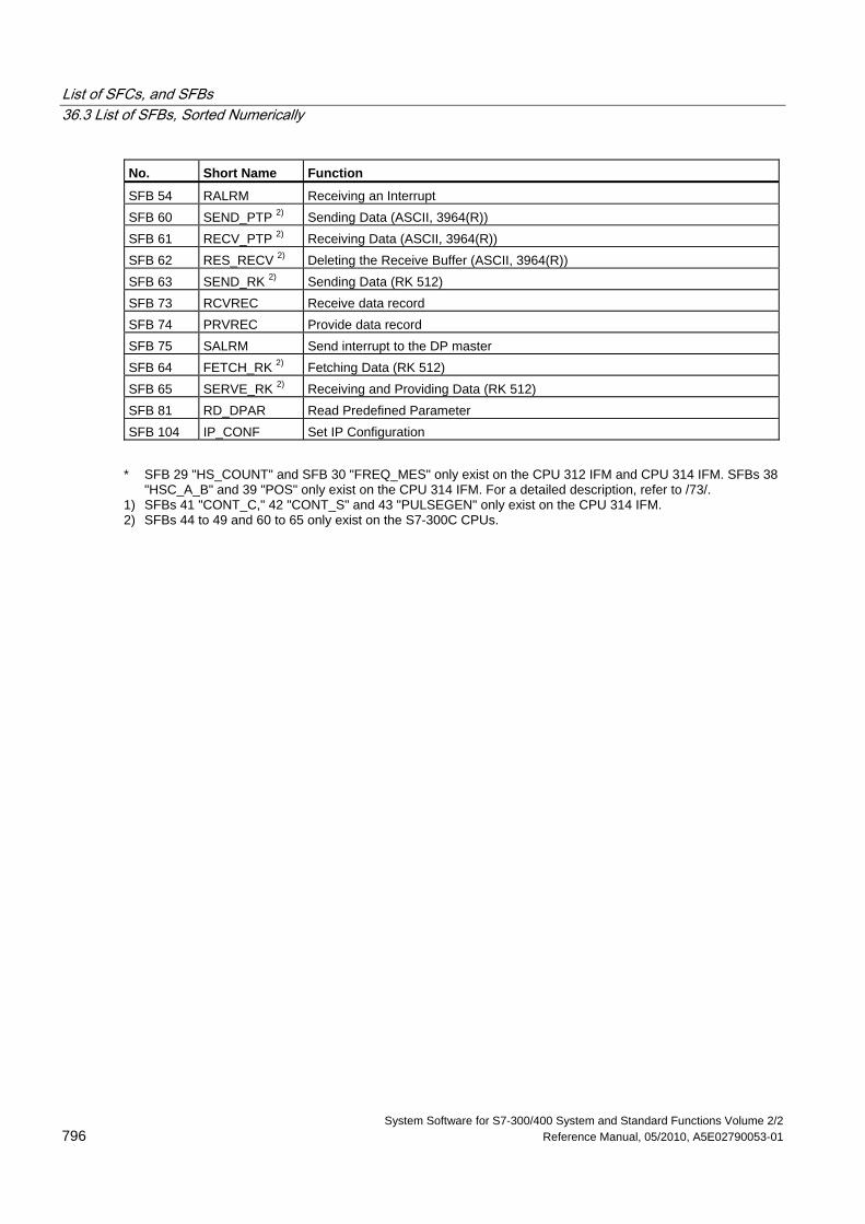
List of SFCs, and SFBs 36.3 List of SFBs, Sorted Numerically
System Software for S7-300/400 System and Standard Functions Volume 2/2 796 Reference Manual, 05/2010, A5E02790053-01
No. Short Name Function
SFB 54 RALRM Receiving an Interrupt SFB 60 SEND_PTP 2) Sending Data (ASCII, 3964(R)) SFB 61 RECV_PTP 2) Receiving Data (ASCII, 3964(R)) SFB 62 RES_RECV 2) Deleting the Receive Buffer (ASCII, 3964(R)) SFB 63 SEND_RK 2) Sending Data (RK 512) SFB 73 RCVREC Receive data record SFB 74 PRVREC Provide data record SFB 75 SALRM Send interrupt to the DP master SFB 64 FETCH_RK 2) Fetching Data (RK 512) SFB 65 SERVE_RK 2) Receiving and Providing Data (RK 512) SFB 81 RD_DPAR Read Predefined Parameter SFB 104 IP_CONF Set IP Configuration
* SFB 29 "HS_COUNT" and SFB 30 "FREQ_MES" only exist on the CPU 312 IFM and CPU 314 IFM. SFBs 38
"HSC_A_B" and 39 "POS" only exist on the CPU 314 IFM. For a detailed description, refer to /73/. 1) SFBs 41 "CONT_C," 42 "CONT_S" and 43 "PULSEGEN" only exist on the CPU 314 IFM. 2) SFBs 44 to 49 and 60 to 65 only exist on the S7-300C CPUs.
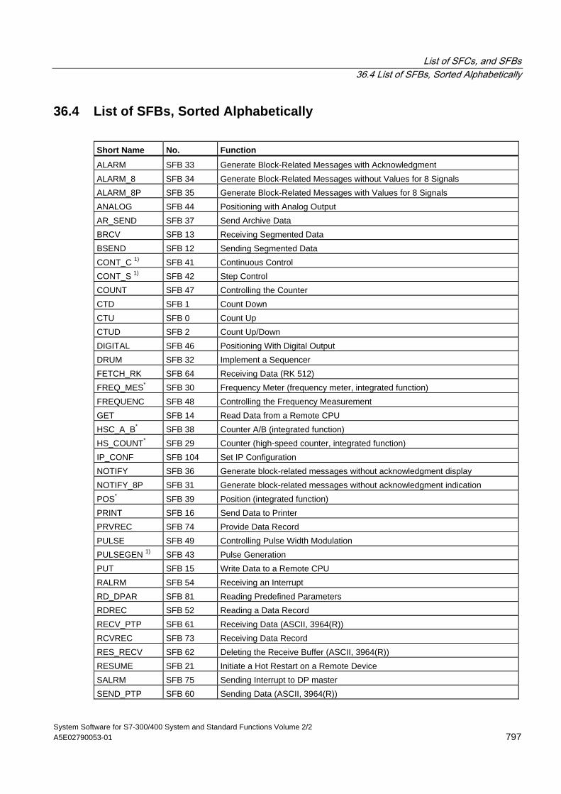
List of SFCs, and SFBs 36.4 List of SFBs, Sorted Alphabetically
System Software for S7-300/400 System and Standard Functions Volume 2/2 A5E02790053-01 797
36.4 List of SFBs, Sorted Alphabetically
Short Name No. Function
ALARM SFB 33 Generate Block-Related Messages with Acknowledgment ALARM_8 SFB 34 Generate Block-Related Messages without Values for 8 Signals ALARM_8P SFB 35 Generate Block-Related Messages with Values for 8 Signals ANALOG SFB 44 Positioning with Analog Output AR_SEND SFB 37 Send Archive Data BRCV SFB 13 Receiving Segmented Data BSEND SFB 12 Sending Segmented Data CONT_C 1) SFB 41 Continuous Control CONT_S 1) SFB 42 Step Control COUNT SFB 47 Controlling the Counter CTD SFB 1 Count Down CTU SFB 0 Count Up CTUD SFB 2 Count Up/Down DIGITAL SFB 46 Positioning With Digital Output DRUM SFB 32 Implement a Sequencer FETCH_RK SFB 64 Receiving Data (RK 512) FREQ_MES* SFB 30 Frequency Meter (frequency meter, integrated function) FREQUENC SFB 48 Controlling the Frequency Measurement GET SFB 14 Read Data from a Remote CPU HSC_A_B* SFB 38 Counter A/B (integrated function) HS_COUNT* SFB 29 Counter (high-speed counter, integrated function) IP_CONF SFB 104 Set IP Configuration NOTIFY SFB 36 Generate block-related messages without acknowledgment display NOTIFY_8P SFB 31 Generate block-related messages without acknowledgment indication POS* SFB 39 Position (integrated function) PRINT SFB 16 Send Data to Printer PRVREC SFB 74 Provide Data Record PULSE SFB 49 Controlling Pulse Width Modulation PULSEGEN 1) SFB 43 Pulse Generation PUT SFB 15 Write Data to a Remote CPU RALRM SFB 54 Receiving an Interrupt RD_DPAR SFB 81 Reading Predefined Parameters RDREC SFB 52 Reading a Data Record RECV_PTP SFB 61 Receiving Data (ASCII, 3964(R)) RCVREC SFB 73 Receiving Data Record RES_RECV SFB 62 Deleting the Receive Buffer (ASCII, 3964(R)) RESUME SFB 21 Initiate a Hot Restart on a Remote Device SALRM SFB 75 Sending Interrupt to DP master SEND_PTP SFB 60 Sending Data (ASCII, 3964(R))
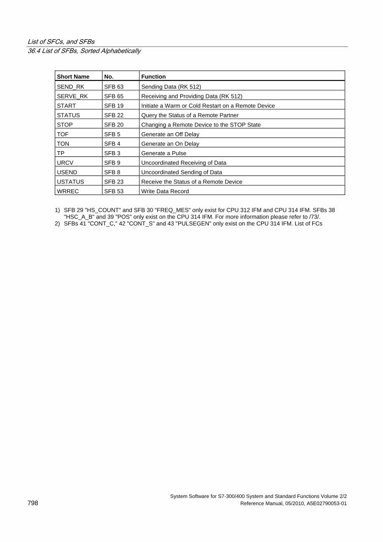
List of SFCs, and SFBs 36.4 List of SFBs, Sorted Alphabetically
System Software for S7-300/400 System and Standard Functions Volume 2/2 798 Reference Manual, 05/2010, A5E02790053-01
Short Name No. Function
SEND_RK SFB 63 Sending Data (RK 512) SERVE_RK SFB 65 Receiving and Providing Data (RK 512) START SFB 19 Initiate a Warm or Cold Restart on a Remote Device STATUS SFB 22 Query the Status of a Remote Partner STOP SFB 20 Changing a Remote Device to the STOP State TOF SFB 5 Generate an Off Delay TON SFB 4 Generate an On Delay TP SFB 3 Generate a Pulse URCV SFB 9 Uncoordinated Receiving of Data USEND SFB 8 Uncoordinated Sending of Data USTATUS SFB 23 Receive the Status of a Remote Device WRREC SFB 53 Write Data Record
1) SFB 29 "HS_COUNT" and SFB 30 "FREQ_MES" only exist for CPU 312 IFM and CPU 314 IFM. SFBs 38
"HSC_A_B" and 39 "POS" only exist on the CPU 314 IFM. For more information please refer to /73/. 2) SFBs 41 "CONT_C," 42 "CONT_S" and 43 "PULSEGEN" only exist on the CPU 314 IFM. List of FCs
System Software for S7-300/400 System and Standard Functions Volume 2/2 Reference Manual, 05/2010, A5E02790053-01 799
Bibliography
/30/ Getting Started: Working with STEP 7
/70/ Manual: PLC S7-300, CPU Specifications CPU 312 IFM to CPU 318-2 DP and S7-300 CPU 31xC and CPU 31x: Technical specifications
/71/ Reference Manual: S7-300 S7-300 Module data
/72/ Instructions List: S7–300 Programmable Controller
/101/ Reference Manual: S7–400, M7–400 Programmable controllers Module Specifications
/102/ Instructions List: S7–400 Programmable Controller
/231/ Manual: Configuring Hardware and Communication Connections, STEP 7
/232/ Reference Manual: Statement List (STL) for S7-300 and S7-400
/233/ Reference Manual: Ladder Logic (LAD) for S7-300 and S7-400
/234/ Manual: Programming with STEP 7
/236/ Reference Manual: Function Block Diagram (FBD) for S7-300 and S7-400
/250/ Manual: Structured Control Language (SCL) for S7-300 and S7-400 Programming
/251/ Manual: S7-GRAPH for S7-300 and S7-400, Programming Sequential Control Systems
/252/ Manual: S7-HiGraph for S7-300 and S7-400, Programming State Graphs
/270/ Manual: S7-PDIAG for S7-300 and S7-400 "Configuring Process Diagnostics for LAD, STL, and FBD"
/350/ User Manual: SIMATIC 7, Standard Controller
Bibliography 36.4 List of SFBs, Sorted Alphabetically
System Software for S7-300/400 System and Standard Functions Volume 2/2 800 Reference Manual, 05/2010, A5E02790053-01
System Software for S7-300/400 System and Standard Functions Volume 2/2 Reference Manual, 05/2010, A5E02790053-01 801
Glossary
Accompanying Value A value that can be output along with a message and provided information about the status of a variable or and address at the time the message was generated.
ACCU (Accumulator) Accumulators are registers in the CPU and serve as buffers for load and transfer operations, as well as for comparison, math, and conversion operations.
Actual Parameter Actual parameters replace formal parameters when a function block (FB) or function (FC) is called, for example, the formal parameter "REQ" is replaced by the actual parameter "I 3.6."
Address The address is the identifier given to a memory location or range of memory locations, for example: input I 12.1; bit memory MW25; data block DB3.
Addressing Assigning an address in the user program. Addresses can be assigned to a memory location or range of memory locations (for example: input I 12.1; bit memory MW25).
Bit Memory This is a 1 bit memory location. Bit memory allows write and read access with STEP 7 basic operations (addressing using bits, bytes, words, and double words). The user can use the bit memory address area to save interim results.
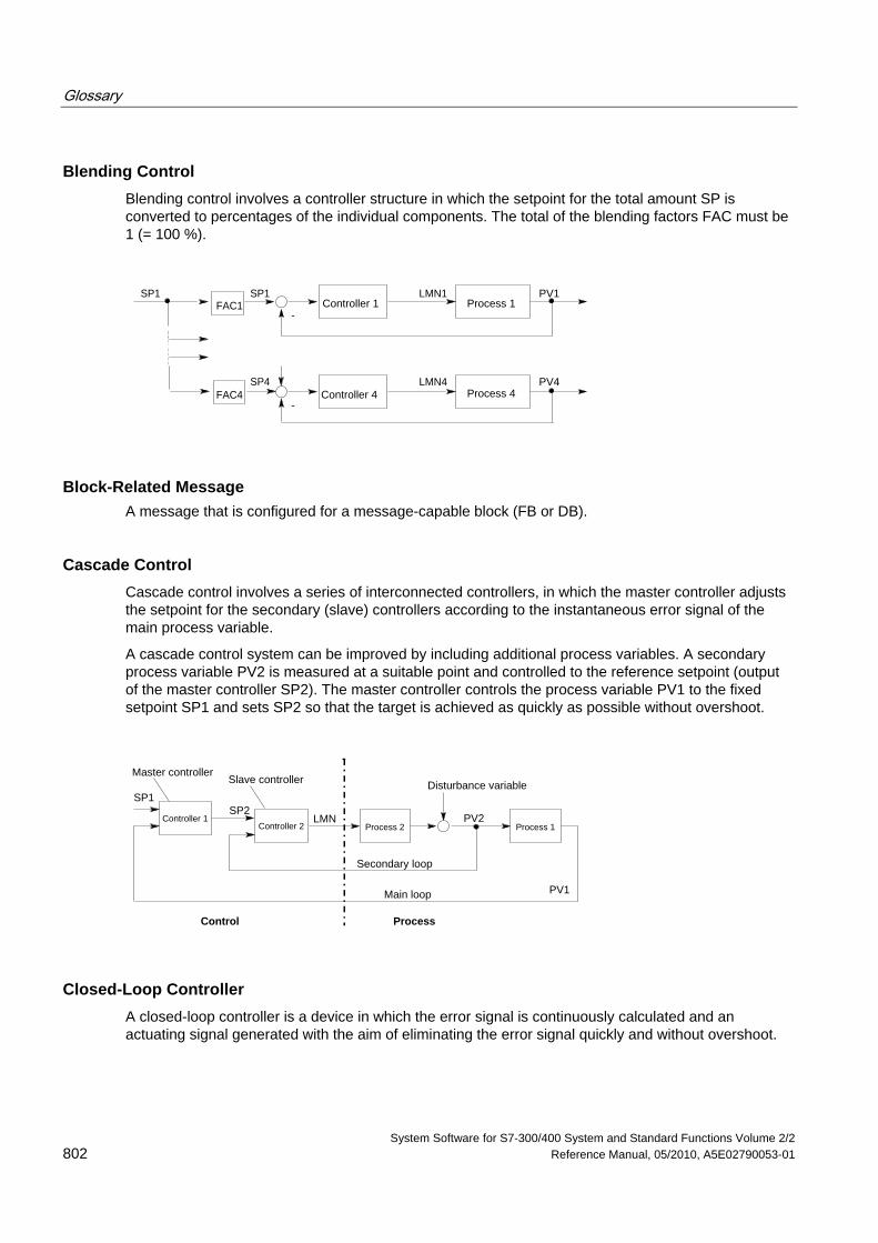
Glossary
System Software for S7-300/400 System and Standard Functions Volume 2/2 802 Reference Manual, 05/2010, A5E02790053-01
Blending Control Blending control involves a controller structure in which the setpoint for the total amount SP is converted to percentages of the individual components. The total of the blending factors FAC must be 1 (= 100 %).
-Controller 1 Process 1
-Process 4Controller 4
FAC1SP1
FAC4SP4
SP1 LMN1 PV1
LMN4 PV4
Block-Related Message A message that is configured for a message-capable block (FB or DB).
Cascade Control Cascade control involves a series of interconnected controllers, in which the master controller adjusts the setpoint for the secondary (slave) controllers according to the instantaneous error signal of the main process variable.
A cascade control system can be improved by including additional process variables. A secondary process variable PV2 is measured at a suitable point and controlled to the reference setpoint (output of the master controller SP2). The master controller controls the process variable PV1 to the fixed setpoint SP1 and sets SP2 so that the target is achieved as quickly as possible without overshoot.
Secondary loop
Main loop
Controller 2 Process 2Controller 1
PV1
SP1SP2
PV2
ProcessControl
Process 1
Disturbance variableMaster controller
Slave controller
LMN
Closed-Loop Controller A closed-loop controller is a device in which the error signal is continuously calculated and an actuating signal generated with the aim of eliminating the error signal quickly and without overshoot.
Glossary
System Software for S7-300/400 System and Standard Functions Volume 2/2 A5E02790053-01 803
Communication, Bilateral When using communication SFBs for data exchange, a distinction is made between unilateral and bilateral communication. Communication is bilateral when there is a SFB on the local and the remote module, for example, the communication SFBs "USEND" and "URCV."
Communication SFBs for Configured Connections Communication SFBs are system function blocks for data exchange and program management.
Examples of data exchange: SEND, RECEIVE, GET.
Examples of program management: setting the CPU of a communication partner to the STOP state, querying the STATUS of the CPU of a communication partner.
Communication SFCs for Non-Configured Connections Communication SFCs are system functions for data exchange and for aborting existing connections established by the communication SFCs.
Communication, Unilateral When using communication SFBs for data exchange, a distinction is made between unilateral and bilateral communication. Communication is unilateral when there is a SFB only on the local module, for example, the SFB "GET."
Complete Restart When a CPU starts up (for example, when the mode selector is moved from STOP to RUN or when power is turned on), before cyclic program processing starts (OB1), either the organization block OB101 (restart; only in the S7-400) or OB100 (complete restart) is processed first. In a complete restart the process-image input table is read in and the STEP 7 user program processed starting with the first statement in OB1.
Constant "Constants" are token values for constant values in logic blocks. Constants are used to improve the legibility of a program. For example, instead of entering a value directly (for example, 10), the token value "Max_iteration_count" is entered in a function block. The value of the constant (for example, 10) is then entered when the block is called.
Continuous Controller A continuous controller is a controller in which every change in the error signal produces a change in the manipulated variable. This can adopt any value within the range of the manipulated variable.
Glossary
System Software for S7-300/400 System and Standard Functions Volume 2/2 804 Reference Manual, 05/2010, A5E02790053-01
Control Device The entire device used to determine the process variable. It consists of a controller, a controlled device (i.e. actuator), and a sensor (measuring device).
Control Loop The control loop is the connection between the process output (process variable) and the controller input and between the controller output (manipulated variable) and the process input, so that the controller and process form a closed loop.
Control System Group Message A group message generated by the CPU operating system when a standard diagnostic event is entered into the diagnostic buffer.
Controller Parameters Controller parameters are characteristic values for the static and dynamic adaptation of the controller response to the given loop or process characteristics.
CPU Operating System The CPU operating system organizes all functions and processes of the CPU that are not linked to a special control task.
Data Block (DB) Data blocks are areas in the user program which contain user data. There are shared data blocks which can be accessed by all logic blocks, and there are instance data blocks which are associated with a particular function block (FB) call.
Diagnostic Buffer The diagnostic buffer is a memory area in the CPU in which all diagnostic events are stored in the order in which they occurred.
Diagnostic Data Diagnostic data is information contained in an error message (diagnostic event, time stamp).
Diagnostic Entry A diagnostic event is described in the diagnostic buffer using a diagnostic entry.
Diagnostic Interrupt Diagnostic modules report recognized system errors using diagnostic interrupts to the CPU.
Glossary
System Software for S7-300/400 System and Standard Functions Volume 2/2 A5E02790053-01 805
Diagnostic Message The diagnostic message consists of a processed diagnostic event and is sent from the CPU to the display unit.
Diagnostics Diagnostic functions incorporate all the system diagnostics and include the recognition, interpretation and reporting of errors within the PLC.
Display Device A device used to display the results of a process.
Error, Asynchronous Asynchronous errors are run time errors which are not assigned to any particular place in the user program (for example, power supply error, scan time overrun). When these errors occur, the operating system calls the corresponding organization blocks in which the user can program a reaction.
Error Handling with OBs If the system program recognizes a particular error (for example, access error in S7), it will call the designated organization block in which the CPU’s response to the error can be set by the user program.
Error OB Error OBs are organization blocks which the user can use to program the reaction to an error. However, a programmed reaction to an error is only possible if the error does not cause the PLC to stop. There is an error OB for each type of error. (For example, error OB for addressing error, error OB for access error in S7.)
Error Reaction Reaction to a run-time error. The operating system can react in the following ways: by changing the PLC to the STOP status, by calling an organization block in which the user can program a reaction, or by displaying the error.
Error, Synchronous Synchronous errors are run-time errors assigned to a particular place in the user program (for example, error accessing an I/O module). When these errors occur, the operating system calls the corresponding organization blocks in which the user can program a reaction.
Glossary
System Software for S7-300/400 System and Standard Functions Volume 2/2 806 Reference Manual, 05/2010, A5E02790053-01
Error, System Error System errors are errors which may occur within a PLC (not in the process). System errors can be, for example program errors in the CPU and faults in modules.
Glossary
System Software for S7-300/400 System and Standard Functions Volume 2/2 A5E02790053-01 807
Formal Parameter A formal parameter is a placeholder for the actual parameter in logic blocks that can be assigned parameters. In FBs and FCs, the formal parameters are declared by the user; in SFBs and SFCs, they already exist. When a block is called, an actual parameter is assigned to the formal parameter so that the called block works with the latest value. The formal parameters belong to the local data of the block and are declared as input, output, and in/out parameters.
Group Error Error message indicated by a LED display on the front panel of modules (only) in S7-300. The LED lights up whenever there is an error in the module concerned (internal errors and external errors).
Hardware Interrupt A hardware interrupt is triggered by modules with interrupt capability as a result of a specific event in the process. The hardware interrupt is reported to the CPU. The assigned organization block is then processed according to the priority of this interrupt.
Input Parameter Input parameters only exist in functions and function blocks. With the help of the input parameters, data are transferred to the called block for processing.
Instruction An instruction (STEP 5 or STEP 7) is the smallest part of a program created in a textual language. It represents a command for the processor.
Integral Component Integral component of the controller.
After a step change in the process variable (or error signal) the output variable changes with a ramp function over time at a rate of change proportional to the integral-action factor KI (= 1/TI). The integral component in a closed control loop has the effect of correcting the controller output variable until the error signal becomes zero.
Integrated Controller An integrated controller is a ready programmed controller block available in the operating system and containing the most important functions of a closed-loop control application. The user can select and deselect functions using software switches.
Glossary
System Software for S7-300/400 System and Standard Functions Volume 2/2 808 Reference Manual, 05/2010, A5E02790053-01
Complete Restart CPU startup mode. The following applies to complete restart mode: Data blocks generated by SFCs will be deleted from work memory, all other data blocks are assigned their default values as in load memory. The process image, times, counters and memory bits will also be reset - irrespective of a remanent memory configuration. During the complete restart, the CPU executes OB 102, reads the process image input table and then continues to process the user program, starting at the first OB 1 instruction.
Interrupt The SIMATIC S7 priority class system recognizes 10 different priority classes, which regulate the processing of the user program. Interrupts belong to these priority classes, for example, hardware interrupts. When an interrupt occurs, the operating system automatically calls an organization block in which the user can program the required reaction (for example, in a function block).
Interrupt, Time-of-Day The time-of-day interrupt belongs to one of the priority classes in SIMATIC S7 program execution. It is generated at a specific date (or day) and time (for example, 9:50 or every hour or every minute). A corresponding organization block is then executed.
Interrupt, Time-Delay The time-delay interrupt belongs to one of the priority classes in SIMATIC S7 program execution. It is generated when a timer has expired in the user program. A corresponding organization block is then executed.
Logic Block In SIMATIC S7, a logic block is a block that contains part of the STEP 7 user program. The other type of block is a data block which contains only data. The following list shows the types of logic blocks:
• Organization block (OB)
• Function block (FB)
• Function (FC)
• System function block (SFB)
• System function (SFC)
Message The report of the occurrence of a event. A message can be output to a suitably configured display device and contains information such as priority, location, and time of the message event as well as information about the state transition (entering the state/leaving the state).
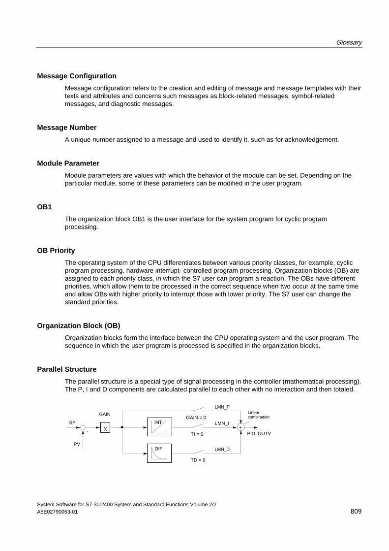
Glossary
System Software for S7-300/400 System and Standard Functions Volume 2/2 A5E02790053-01 809
Message Configuration Message configuration refers to the creation and editing of message and message templates with their texts and attributes and concerns such messages as block-related messages, symbol-related messages, and diagnostic messages.
Message Number A unique number assigned to a message and used to identify it, such as for acknowledgement.
Module Parameter Module parameters are values with which the behavior of the module can be set. Depending on the particular module, some of these parameters can be modified in the user program.
OB1 The organization block OB1 is the user interface for the system program for cyclic program processing.
OB Priority The operating system of the CPU differentiates between various priority classes, for example, cyclic program processing, hardware interrupt- controlled program processing. Organization blocks (OB) are assigned to each priority class, in which the S7 user can program a reaction. The OBs have different priorities, which allow them to be processed in the correct sequence when two occur at the same time and allow OBs with higher priority to interrupt those with lower priority. The S7 user can change the standard priorities.
Organization Block (OB) Organization blocks form the interface between the CPU operating system and the user program. The sequence in which the user program is processed is specified in the organization blocks.
Parallel Structure The parallel structure is a special type of signal processing in the controller (mathematical processing). The P, I and D components are calculated parallel to each other with no interaction and then totaled.
-
Linearcombination
LMN_ISP
PV
+TI = 0
TD = 0
GAIN = 0INT
DIF LMN_D
GAIN
X
LMN_P
PID_OUTV
Glossary
System Software for S7-300/400 System and Standard Functions Volume 2/2 810 Reference Manual, 05/2010, A5E02790053-01
Parameter 1. A parameter is a variable of an S7 logic block
(see block parameter actual parameter formal parameter)
2. A variable for setting the behavior of a module
(one or more per module)
Every configurable module has a basic parameter setting when it is supplied from the factory, but this can be changed using STEP 7.
(one or more per module).
There are two types of parameter:
static and dynamic parameters parameter, static/ parameter, dynamic).
Parameter, Dynamic Dynamic parameters of modules, in contrast to static parameters, can be changed by the user program during operation by calling an SFC, for example, limit values of an analog module.
Parameter, Static Static parameters of modules, in contrast to dynamic parameters, cannot be changed by the user program, but only using STEP 7, for example, the input delay of a digital input module.
P Algorithm Algorithm for calculating an output signal in which there is a proportional relationship between the error signal and manipulated variable change. Characteristics: steady-state error signal, not to be used with processes including dead time.
PI Algorithm Algorithm for calculating an output signal in which the change in the manipulated variable is made up of a component proportional to the error signal and an I component proportional to the error signal and time. Characteristics: no steady-state error signal, faster compensation than with an I algorithm, suitable for all processes.
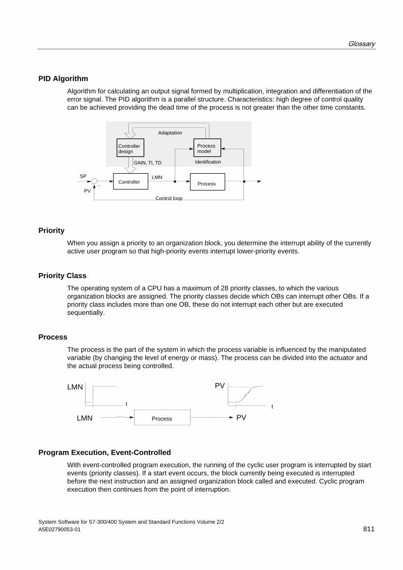
Glossary
System Software for S7-300/400 System and Standard Functions Volume 2/2 A5E02790053-01 811
PID Algorithm Algorithm for calculating an output signal formed by multiplication, integration and differentiation of the error signal. The PID algorithm is a parallel structure. Characteristics: high degree of control quality can be achieved providing the dead time of the process is not greater than the other time constants.
-LMNSP
PV
Controller Process
Control loop
Processmodel
Controller design
GAIN, TI, TD Identification
Adaptation
Priority When you assign a priority to an organization block, you determine the interrupt ability of the currently active user program so that high-priority events interrupt lower-priority events.
Priority Class The operating system of a CPU has a maximum of 28 priority classes, to which the various organization blocks are assigned. The priority classes decide which OBs can interrupt other OBs. If a priority class includes more than one OB, these do not interrupt each other but are executed sequentially.
Process The process is the part of the system in which the process variable is influenced by the manipulated variable (by changing the level of energy or mass). The process can be divided into the actuator and the actual process being controlled.
t
Process
t
LMN
PV
PV
LMN
Program Execution, Event-Controlled With event-controlled program execution, the running of the cyclic user program is interrupted by start events (priority classes). If a start event occurs, the block currently being executed is interrupted before the next instruction and an assigned organization block called and executed. Cyclic program execution then continues from the point of interruption.
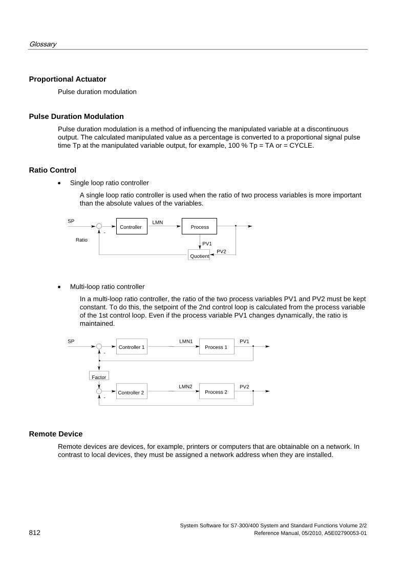
Glossary
System Software for S7-300/400 System and Standard Functions Volume 2/2 812 Reference Manual, 05/2010, A5E02790053-01
Proportional Actuator Pulse duration modulation
Pulse Duration Modulation Pulse duration modulation is a method of influencing the manipulated variable at a discontinuous output. The calculated manipulated value as a percentage is converted to a proportional signal pulse time Tp at the manipulated variable output, for example, 100 % Tp = TA or = CYCLE.
Ratio Control • Single loop ratio controller
A single loop ratio controller is used when the ratio of two process variables is more important than the absolute values of the variables.
SP
-
LMN
Quotient
RatioPV1
PV2
Controller Process
• Multi-loop ratio controller
In a multi-loop ratio controller, the ratio of the two process variables PV1 and PV2 must be kept constant. To do this, the setpoint of the 2nd control loop is calculated from the process variable of the 1st control loop. Even if the process variable PV1 changes dynamically, the ratio is maintained.
SP
-
LMN1Controller 1 Process 1
-
Factor
PV2
PV1
Process 2Controller 2LMN2
Remote Device Remote devices are devices, for example, printers or computers that are obtainable on a network. In contrast to local devices, they must be assigned a network address when they are installed.
Glossary
System Software for S7-300/400 System and Standard Functions Volume 2/2 A5E02790053-01 813
Restart When a CPU starts up (for example, when the mode selector is moved from STOP to RUN or when the power is turned on), before cyclic program processing starts (OB1), either the organization block OB100 (restart) or the organization block OB101 (restart; only in the S7-400) or the organization block OB 102 (complete restart) (complete restart) is processed first. In a restart the process-image input table is read in and the STEP 7 user program processing is restarted at the point where it was interrupted by the last stop (STOP, power off).
Result of Logic Operation (RLO) The result of logic operation (RLO) is the current signal state in the processor which is used for further binary signal processing. The signal state of the last RLO decides whether or not certain operations are executed.
Run-time Error Errors which occur during execution of the user program in the PLC (not in the process).
SCAN An operating system function integrated in the CPU that is used to scan for and detect a signal at set intervals in order to determine if a signal change has occurred.
Standard Function Standard functions are function blocks available from SIEMENS for implementing complex tasks.
Standard Function Block Standard function blocks are function blocks available from SIEMENS for implementing complex tasks.
Start Event Start events are defined events such as errors or interrupts which prompt the operating system to call the appropriate organization block.
Start Event Information The start event information is part of an organization block (OB). Start event information provides the S7 user with detailed information about the event which triggered the call for the OB. The start event information contains the event number (consisting of event classes and event IDs), an event time stamp, and additional information (for example, the address of the interrupt-activating signal module).
Glossary
System Software for S7-300/400 System and Standard Functions Volume 2/2 814 Reference Manual, 05/2010, A5E02790053-01
Start Information When the operating system calls an organization block, the operating system transfers start information which can be interpreted in the user program.
Startup OB Depending on the setting of the startup mode selector (only S7-400), the reason for the startup (return of power after outage, manual switch from STOP to RUN with the mode selector or command from the programming device) either the startup organization block "Complete restart" or "Restart" (only exists on the S7-400) is called by the operating system. In the startup OB, the SIMATIC S7 user can, for example, program how the system will start up again after a power outage.
An instruction (STEP 5 or STEP 7) is the smallest part of a program created in a textual language. It represents a command for the processor.
Statement List The Statement List is the assembly language of STEP 7. When a program is processed in STL, the individual instructions correspond to the sequence with which the CPU processes the program.
STEP 7 Programming software for creating user programs for SIMATIC S7 controllers.
STEP 7 Programming Language Programming language for SIMATIC S7 controllers. The S7 programmer can use STEP 7 in different representation types: a) Statement List, b) Control System Flowchart, c) Ladder Logic.
Step Controller A step controller is a quasi continuous controller with a discontinuous output (and motor-driven actuator with an I action). The actuator has a three-step response, for example, up - stop - down (or open - hold – close).
(Three-step controller).
STL Statement List.
Subnumber The number of the signal to be monitored if a message block can monitor more than one signal.
Glossary
System Software for S7-300/400 System and Standard Functions Volume 2/2 A5E02790053-01 815
Symbol-Related Message A message used in configuring messages for a symbol (input, output, bit memory, data block) in the symbol table. During configuration, the time interval must be set for the SCAN function used to monitor the signal.
Glossary
System Software for S7-300/400 System and Standard Functions Volume 2/2 816 Reference Manual, 05/2010, A5E02790053-01
Symbolic Programming The STEP 7 programming language allows the use of symbolic names instead of STEP 7 addresses. For example, a STEP 7 address "Q 1.1" can be replaced with "Valve 17."
The symbol list in STEP 7 also creates the link between the address and the assigned symbolic name.
System Diagnostics The detection and evaluation of system diagnostic events.
System Diagnostic Event An entry which is made in the diagnostic buffer of the CPU and is used to initialize operating system.
System Function (SFC) A system function (SFC) is a function which is integrated in the CPU operating system and can be called in the STEP 7 user program as required.
System Function Block (SFB) A system function block (SFB) is a function block integrated in the CPU operating system which can be called in the STEP 7 user program when required.
Three-Step Controller A controller that can only adopt three discrete states; for example, "heat - off cool" or "right - stop - left" (step controller).
Time-Delay Interrupt The time-delay interrupt belongs to one of the priority classes used in SIMATIC S7 program processing. This interrupt is generated in the user program after a specified time has elapsed and is processed in the associated organization block.
Tool A software feature used for configuring and programming.
Two-step Controller A two-step controller is a controller that can only set two states for the manipulated variable (for example, on - off).
User-Defined Diagnostics The detection and evaluation of user-defined diagnostic events.
Glossary
System Software for S7-300/400 System and Standard Functions Volume 2/2 A5E02790053-01 817
User-Defined Diagnostic Event A diagnostic event detected by the user which can be placed into the diagnostic buffer (with SFC 52).
User-Defined Diagnostic Message A message reporting the occurrence of a user-defined diagnostic event.
User Program The user program contains all the statements and declarations and the data for signal processing with which a system or process can be controlled. It is assigned to a programmable module (module, programmable) and can be structured in smaller units known as blocks.
User Program Error Errors which may occur during the processing of the user program in a SIMATIC S7 PLC (in contrast to process errors). The operating system handles errors using error OBs (priority class system), the status word and output parameters from system functions.
Variable A variable defines a data with variable contents that can be used in the STEP 7 user program. A variable consists of an address (for example, M 3.1) and a data type (for example, BOOL) and is represented by a symbol (for example, MOTOR_ON).
Variable Declaration The variable declaration incorporates the entry of a symbolic name, a data type and possibly a default value, address and comment.

Glossary
System Software for S7-300/400 System and Standard Functions Volume 2/2 818 Reference Manual, 05/2010, A5E02790053-01
System Software for S7-300/400 System and Standard Functions Volume 2/2 Reference Manual, 05/2010, A5E02790053-01 819
Index
" "DPRD_DAT" 307
A Aborting an Existing Connection to a Communication
Partner outside the Local S7 Station with SFC 69 "X_ABORT" 448
Aborting an Existing Connection to a Communication Partner within the Local S7 Station with SFC 74 "I_ABORT" 453
Access error for CPU 417 and CPU 417H: 215 Access error mask for CPU 417 and CPU 417H: 215 Access error mask: 215 Access error: 215 ACCFLT_ESR 225 ACCFLT_MASKED 223, 224 ACCFLT_QUERY 225 ACCFLT_RESET_MASK 224 ACCFLT_SET_MASK 223 ACT_TINT 206 Activating a Time-of-Day Interrupt with SFC 30
"ACT_TINT" 206 Activating write-protection with SFC 109 "PROTECT"
128 ADC/DAC error 692 Additional Error Information Of The SFBs 60 To 65 671 ALARM: 512 ALARM_8: 518 ALARM_8P: 515 ALARM_D 537 ALARM_DQ 537 ALARM_S: 532 ALARM_SC 535 ALARM_SQ 532 Alignment error when reading: 215 Alignment error when writing: 215 Alignment error: 215 AR_SEND: 520 Area error when reading: 215 Area error when writing: 215 Area error: 215 Assembly Code Block
Calling 689 Assigning Parameters to a Module with SFC 57
"PARM_MOD" 153 Asynchronous error 227, 229, 230, 231, 233, 234
delaying with SFC 41 DIS_AIRT 233 disabling with SFC 39 DIS_IRT 229 enabling with SFC 40 EN_IRT 231 enabling with SFC 42 EN_AIRT 234
Asynchronous error: 772
Asynchronous errors 50 OB80 50
B Background Information on the SFCs 112 to 114 313 Background Organization Block (OB90) 75 Battery backup 692
failed 692 Battery exhausted 692 BCD conversion error: 215 Bibliography 799 Bit field in the I/O area 271
setting with SFC 79 271 BLK 103 BLKMOV 99 Block number error: 215 Block types: 710 BRCV 385 BSEND 380 BVAL 102
C C_CNTRL 428 C_DIAG 254 Calling an Assembly Code Block: 689 CAN_DINT 214 CAN_TINT 205 Canceling a Time-Delay Interrupt with SFC 33
"CAN_DINT" 214 Canceling a Time-of-Day Interrupt with SFC 29
"CAN_TINT" 205 CDT 132 Changing a Remote Device to the STOP State with SFB
20 "STOP" 415 Changing the CPU to STOP with SFC 46 "STP" 123 Channel 691, 692, 693
error 691 information 692
Characteristics of SFCs 28 to 31 202 CiR 126, 127 CiR Operation 57 Classification and Work Memory Requirements of the S7
Communication SFBs 354 Clearing The Input Buffer 655 Clock
Master: 131 Synchronization: 131
Clock: 131 Common mode error 694
analog input module 694 analog output module 694
Common Parameters of the Communication SFCs: 431
Index
System Software for S7-300/400 System and Standard Functions Volume 2/2 820 Reference Manual, 05/2010, A5E02790053-01
Common Parameters of the SFBs/FBs and SFCs/FCs for S7 Communication 361
Communication 228, 722 error: 227 interrupt 227 status data: 722
Communication Error Organization Block (OB87) 71 Communication events: 778 Communication Redundancy Error OB (OB73) 49 Communication SFCs 358, 359, 360 Communication SFCs for non-configured S7 connections
358, 359, 360 classification: 357
Complete restart 77, 412, 414 Component Identification 711 COMPRESS: 110 Compressing the User Memory with SFC 25
"COMPRESS" 110 Configuration 694
error analog input module 694 analog output module 694 digital input module 694
Connection 254, 255, 256, 257, 258, 428 diagnostics with SFC 87 254 Status S-300 (FC62) 428
CONT_C 584 CONT_S 589 Continuous Control with SFB 41/FB 41 "CONT_C" 581 Control 581, 585, 587, 589, 590, 593
continuous control with SFB 41 581 step control with SFB 42 589
CONTROL 425 Controlling CiR with SFC 104 "CiR" 126 Controlling Operation in H Systems with SFC 90
"H_CTRL" 679 Controlling Operation in H Systems with SFC 90: 679 Controlling Positioning With Analog Output Via User
Program 609 Controlling positioning with digital output with the user
program 623 Controlling Pulse Width Modulation Via User Program
646 Controlling the Counter via User Program 636 Controlling The Frequency Measurement Via User
Program 641 Copying variables 97
with SFC 20 BLKMOV 97 Copying Variables with SFC 20 "BLKMOV" 97 COUNT 105 Count down: 552 Count up: 551 Counter (CPU 312) 683 Counter number error: 215 Counting Down with SFB 1 "CTD" 552 Counting Up with SFB 0 "CTU" 551 CPU 123, 227, 228, 703, 704
changing to the STOP mode with SFC 46 STP: 123 characteristics: 703 hardware fault 228
CPU hardware fault OB 61
CPU Hardware Fault Organization Block (OB84) 61 CPU Redundancy Error OB (OB72) 46 CQ 143 CREA_DB 120 CREA_DBL 113 CREATE_DB 105 Creating a Data Block 120 Creating a Data Block with SFC 22 "CREAT_DB" 105 Creating a Data Block with SFC 85 "CREA_DB" 120 CTD 552 CTRL_RTM 142 CTU 551 CTUD 553 Current below measuring range 694
analog input module 694 CV 143 Cycle time monitoring 691 Cyclic interrupt OBs (OB30 to OB38): 24 Cyclic interrupt: 24 Cyclic interrupts 227
D Data 310, 311, 312
Writing Consistent Data to DP Standard Slave/PROFINET IO Device 310
Data block 105, 107, 118, 119 creating with SFC 22 CREAT_DB 105 deleting with SFC 23 107
Data Block 116, 117 Reading from a Data Block in Load Memory with SFC
83 "READ_DBL" 116 Data Consistency with GET and PUT SFCs: 352 Data record 146, 147, 156, 158, 159, 160, 161, 162
reading 145 reading with SFC 59 RD_REC 158 writing 145 writing with SFC 58 WR_REC 156
Data Record 165, 166 Reading with SFB 52 RDREC 165 Writing with SFB 53 WRREC 167
Data record of the Partial List Extract with SSL ID W#16#0132 and Index W#16#000B 726
Data record of the Partial List Extract with SSL ID W#16#0132 and Index W#16#000C 727
Data Record of the Partial List Extract with SSL-ID W#16#0132 Index W#16#0005: 723
Data Record of the Partial List Extract with SSL-ID W#16#0132 Index W#16#0008: 724
Data Record of the Partial List Extract with SSL-ID W#16#0232 Index W#16#0004: 728
Date and Time as Complex Data Types 559 Date: 131 Datensatz 167 DB_NUMBER 105 Deactivating and Activating DP Slaves/PROFINET IO
Devices with SFC 12 "D_ACT_DP" 296 DEL_DB 107 DEL_SI 544 Delay time: 209
Index
System Software for S7-300/400 System and Standard Functions Volume 2/2 A5E02790053-01 821
Delaying and Disabling Interrupts and Asynchronous Errors 227
Delaying Execution of the User Program with SFC 47 "WAIT" 124
Delaying the Processing of Higher Priority Interrupts and Asynchronous Errors with SFC 41 "DIS_AIRT" 233
Delaying the user program 124 with SFC 47 WAIT 124
Deleting a Data Block with SFC 23 "DEL_DB" 107 Determining the OB Program Run Time with SFC 78
"OB_RT" 249 Determining the Slot Belonging to a Logical Address with
SFC 71 "LOG_GEO" 284 Determining the Start Address of a Module with SFC 70
"GEO_LOG" 282 Device Status Change 422
Receiving the Status Change of a Remote Device 422
Diagnosis of the Current Connection Status with SFC 87 "C_DIAG" 254
Diagnostic buffer: 215, 697, 760 Diagnostic data 146, 691, 697, 698
content: 691 of the CPU 697 of the signal modules 697 of the signal modules: 145 structure 691
Diagnostic Data 691 Diagnostic data of a module 691 Diagnostic events: 783 Diagnostic interrupt 228, 692
from substitute 691 Diagnostic Interrupt Organization Block (OB82) 55 Diagnostics with SFC 87 254 Differences between the Blocks of the S7 Communication
and the S7 Basic Communication 349 DIS_AIRT 233 DIS_IRT 229 DIS_MSG: 523 Disabling the Processing of New Interrupts and
Asynchronous Errors with SFC 39 "DIS_IRT" 229 DMSK_FLT 224 DP Master System Information 737 DP_PRAL 287 DP_TOPOL 259 DPNRM_DG: 303 DPRD_DAT 307 DPSYC_FR: 290 DPWR_DAT 310 DRUM 274 DSTBLK 98, 99 DTIME 211
E EN_AIRT 234 EN_IRT 231 EN_MSG: 525 Enabling Block-Related
Symbol-Related and Group Status Messages with SFC 9 "EN_MSG"
525 Enabling or synchronizing user Web pages with SFC99
"WWW" 319 Enabling the Processing of Higher Priority Interrupts and
Asynchronous Errors with SFC 42 "EN_AIRT" 234 Enabling the Processing of New Interrupts and
Asynchronous Errors with SFC 40 "EN_IRT" 231 Error 227, 228, 691, 692, 693
ADC/DAC 692 asynchronous 227 EPROM 692 RAM 692
Error detection 50, 82, 85 types of OB
OB121 82 OB122 85 OB80 50
Error handling: 215 Error information 106, 107, 108, 213, 232, 234
SFC 22 CREAT_DB: 105 SFC 23 DEL_DB: 107 SFC 34 QRY_DINT: 212 SFC 40 EN_IRT: 231 SFC 42 EN_AIRT: 234
Error Information of the Communication SFCs for Non-Configured S7 Connections: 433
Error interrupt 227 asynchronous 227, 228 synchronous 227
Error mask Access error: 215 Programming error: 215
Error mask: 215 Error OB 50, 53, 55, 62
types of OB OB80 50, 51 OB81 53 OB82 55 OB85 62, 63, 64, 65
Error OB: 215 Error register 225
reading with SFC 38 READ_ERR 225 Error register: 215 Establishing a Connection with FB 65 "TCON" 482 Evaluating Errors with the Output Parameter RET_VAL
87 Event 245, 246, 247, 248, 767, 768
class: 767 ID 246, 247, 767, 768
Event Class 1 - Standard OB Events 768 Event Class 2 - Synchronous Errors 769
Index
System Software for S7-300/400 System and Standard Functions Volume 2/2 822 Reference Manual, 05/2010, A5E02790053-01
Event Class 3 - Asynchronous Errors 772 Event Class 4 - Stop Events and Other Mode Changes
776 Event Class 5 - Mode Runtime Events: 777 Event Class 6 - Communication Events 778 Event Class 7 - H/F Events 780 Event Class 8 - Diagnostic Events for Modules 783 Event Class 9 - Standard User Events 785 Event Classes A and B - Free User Events 787 EVENTN 245 Events and Event ID 767 Example of the PULSEGEN Block: 606 Expansion rack failure 692 External error 691
F FB 12 BSEND 378 FB 13 BRCV 382 FB 15 PUT 398 FB 20 GETIO 336 FB 21 SETIO 337 FB 210 "FW_TCP" 501 FB 22 GETIO_PART 338 FB 220 "FW_IOT" 502 FB 23 SETIO_PART 340 FB 28 "USEND_E" 386 FB 34 "GET_E" 392 FB 35 "PUT_E" 395 FB 63 "TSEND" 488 FB 64 "TRCV" 491, 492, 493 FB 65 "TCON" 482, 483 FB 66 "TDISCON" 486 FB 67 "TUSEND" 495 FB 68 "TURCV" 498, 499 FB 8 USEND 370 FB 9 URCV 374 FB29 "URCV_E" 389, 391 FBs for Cyclical Access to User Data
Introduction 335 FC1 560 FC10 572 FC11 568 FC12 564 FC13 572 FC14 565 FC15 573 FC16 575 FC17 568 FC18 565 FC19 573 FC2 567 FC20 569 FC21 569 FC22 578 FC23 566 FC24 574 FC25 578 FC26 570 FC27 579
FC28 566 FC29 574 FC3 560 FC30 575 FC31 570 FC32 571 FC33 562 FC34 562 FC35 563 FC36 580 FC37 576 FC38 576 FC39 577 FC4 567 FC40 563 FC5 575 FC6 561 FC62 428 FC7 561 FC8 562 FC9 564 FILL 102 Free user events: 787 Frequency Meter (CPU 312) 685 Further Error Information for SFCs 55 to 59: 163 Fuse tripped 692 FW_IOT 502 FW_TCP 501
G GADR_LGC: 277 GD packet 343, 344, 345, 346, 347, 348
Programmed Acceptance with SFC 61 346 sending with SFC 60 343
GD_RCV 346 GD_SND: 343 Generating a Data Block 113
with SFC 82 "CREA_DBL 113 Generating a Data Block in the Load Memory with SFC
82 "CREA_DBL" 113 Generating a Pulse with SFB 3 "TP" 547 Generating Acknowledgeable and Permanently
Acknowledged Block Related Messages with SFC 107 "ALARM_DQ" 537
Generating Acknowledgeable and Permanently Acknowledged Block Related Messages with SFC 108 "ALARM_D" 537
Generating Acknowledgeable Block-Related Messages with SFC 17 "ALARM_SQ" and Permanently Acknowledged Block-Related Messages with SFC 18 "ALARM_S" 532
Generating an Off Delay with SFB 5 "TOF" 550 Generating an On Delay with SFB 4 "TON" 549 Generating Block Related Messages without
Acknowledgement Display with SFB 31 "NOTIFY_8P" 509
Generating Block-Related Messages with Accompanying Values for Eight Signals with SFB 35 "ALARM_8P" 515
Index
System Software for S7-300/400 System and Standard Functions Volume 2/2 A5E02790053-01 823
Generating Block-Related Messages with Acknowledgment with SFB 33 "ALARM" 512
Generating Block-Related Messages without Acknowledgment with SFB 36 "NOTIFY" 507
Generating Block-Related Messages without Associated Values for Eight Signals with SFB 34 "ALARM_8" 518
GEO_LOG 282 GET 402 GET_E 392 GETIO 336 GETIO_PART 338 Glossary 801 Ground error 695
digital input module 694 Groups of DP slaves 290
synchronizing 290
H H/F events: 780 H_CTRL 679 Handling Runtime meters with SFC 101 "RTM" 139 Handling Time-Delay Interrupts 209 Handling Time-of-Day Interrupts 201 Hardware interrupt 227, 692
lost: 691 Hardware interrupt OBs 26 Hardware Interrupt Organization Blocks (OB40 to OB47)
26 How SFBs for S7 Communication React to Problems
368 How the SFBs for Generating Block-Related Messages
React to Problems: 528
I I/O Access Error Organization Block (OB122) 85 I/O access error when reading: 215 I/O access error when writing: 215 I/O access error: 215 I/O Redundancy Error OB (OB70) 44 I_ABORT: 453 I_GET: 449 I_PUT: 451 Identifying the Bus Topology of a DP Master System
259 Implementing a Sequencer with SFB 32 "DRUM" 273 INFO1 245 INFO2 247, 248 Initializing a memory area 102
with SFC 21 FILL 102 Initializing a Memory Area with SFC 21 "FILL" 102 Initiating a Hot Restart on a Remote Device with SFB 21
"RESUME" 418 Initiating a Warm or Cold Restart on a Remote Device
with SFB 19 "START" 412 INSERT 568 Insert/Remove OB (OB83) 57 Integrated Counter Function: 683
Integrated Frequency Meter Function: 685 Interface DB 313, 314, 315 Internal error 691 Interrupt 22, 23, 28, 29, 30, 31, 227, 229, 230, 231,
233, 234 classes 227 delaying with SFC 41 DIS_AIRT 233 disabling with SFC 39 DIS_IRT 229 DPV1 Interrupt 28 enabling with SFC 40 EN_IRT 231 enabling with SFC 42 EN_AIRT 234
Interrupt Class 57 Interrupt OBs 55
diagnostic interrupts: 55 time-of-day interrupts 19
Interrupt Status 716 Interrupts 18, 26, 32, 36, 57
cyclic interrupt: 24 DPV1 Interrupt 32 DPV1-Interrupt 36 hardware interrupt OBs 26, 27 Insert/Remove Interrupt 57 Manufacturer specific interrupt 36 Status Interrupt 28, 29, 30 time-delay 22, 23 Update Interrupt 32, 34
Interrupts: 24 Introduction to Generating Block-Related Messages with
SFBs: 503 Introduction to Generating Block-Related Messages with
SFCs: 529 IOID 150, 152, 153, 156, 158 IP_CONF 321
L LADDR 150, 152, 153, 154, 156, 158 LEFT 569 LGC_GADR 279 LIMIT 578 Linking to a Third-Party System with FB 210 "FW_TCP"
using the FETCH and WRITE Services via TCP 501 Linking to a Third-Party System with FB 220 "FW_IOT"
using the FETCH and WRITE Services via ISO-on-TCP 502
List of SFBs Sorted Alphabetically: 797 Sorted Numerically: 795
List of SFCs Sorted Alphabetically: 792 Sorted Numerically: 789
Local data of the OBs: 732 LOG_GEO 284 Logical address 277, 281
of a channel querying 277
of a module querying all addresses 281
LOW_LIMIT 105
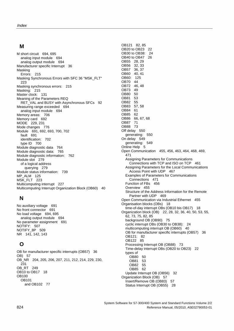
Index
System Software for S7-300/400 System and Standard Functions Volume 2/2 824 Reference Manual, 05/2010, A5E02790053-01
M M short circuit 694, 695
analog input module 694 analog output module 694
Manufacturer specific Interrupt 36 Masking
Errors: 215 Masking Synchronous Errors with SFC 36 "MSK_FLT"
223 Masking synchronous errors: 215 Masking: 215 Master clock: 131 Meaning of the Parameters REQ
RET_VAL and BUSY with Asynchronous SFCs 92 Measuring range exceeded 694
analog input module 694 Memory areas: 706 Memory card 692 MODE 229, 231 Mode changes 776 Module 691, 692, 693, 700, 702
fault 691 identification: 702 type ID 700
Module diagnostic data 764 Module diagnostic data: 765 Module diagnostic information: 762 Module slot 279
of a logical address querying 279
Module status information: 739 MP_ALM 125 MSK_FLT 223 Multicomputing interrupt 227 Multicomputing Interrupt Organization Block (OB60) 40
N No auxiliary voltage 691 No front connector 691 No load voltage 694, 695
analog output module 694 No parameter assignment 691 NOTIFY: 507 NOTIFY_8P 509 NR 141, 142, 143
O OB for manufacturer specific interrupts (OB57) 36 OB) 57 OB_NR 204, 205, 206, 207, 211, 212, 214, 229, 230,
231 OB_RT 249 OB10 to OB17 18 OB100
OB101 and OB102 77
OB121 82, 85 OB20 to OB23 22 OB30 to OB38: 24 OB40 to OB47 26 OB55 28, 29 OB56 32, 33 OB57 36, 37 OB60 40, 41 OB60: 125 OB70 44 OB72 46, 48 OB73 49 OB80 50 OB81 53 OB82 55 OB83 57, 58 OB84 61 OB85 62 OB86 66, 67, 68 OB87 71 OB88 73 Off delay 550
generating: 550 On delay 549
generating: 549 Online Help 5 Open Communication 455, 456, 463, 464, 468, 469,
471 Assigning Parameters for Communications
Connections with TCP and ISO on TCP 461 Assigning Parameters for the Local Communications
Access Point with UDP 467 Examples of Parameters for Communications
Connections 471 Function of FBs 456 Overview 455 Structure of the Address Information for the Remote
Partner with UDP 469 Open Communication via Industrial Ethernet 455 Organisation blocks (OBs) 18
time-of-day interrupt OBs (OB10 bis OB17) 18 Organization block (OB) 22, 28, 32, 36, 40, 50, 53, 55,
62, 73, 75, 82, 85 background OB (OB90) 75 cyclic interrupt OBs (OB30 to OB38): 24 multicomputing interrupt OB (OB60) 40 OB for manufacturer specific interrupts (OB57) 36 OB121: 82 OB122 85 Processing Interrupt OB (OB88) 73 Time-delay interrupt OBs (OB20 to OB23) 22 types of
OB80 50 OB81 53 OB82 55 OB85 62
Update Interrupt OB (OB56) 32 Organization Block (OB) 57
Insert/Remove OB (OB83) 57 Status Interrupt OB (OB55) 28
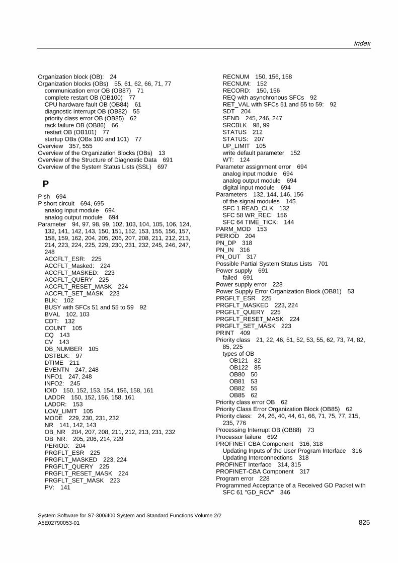
Index
System Software for S7-300/400 System and Standard Functions Volume 2/2 A5E02790053-01 825
Organization block (OB): 24 Organization blocks (OBs) 55, 61, 62, 66, 71, 77
communication error OB (OB87) 71 complete restart OB (OB100) 77 CPU hardware fault OB (OB84) 61 diagnostic interrupt OB (OB82) 55 priority class error OB (OB85) 62 rack failure OB (OB86) 66 restart OB (OB101) 77 startup OBs (OBs 100 and 101) 77
Overview 357, 555 Overview of the Organization Blocks (OBs) 13 Overview of the Structure of Diagnostic Data 691 Overview of the System Status Lists (SSL) 697
P P sh 694 P short circuit 694, 695
analog input module 694 analog output module 694
Parameter 94, 97, 98, 99, 102, 103, 104, 105, 106, 124, 132, 141, 142, 143, 150, 151, 152, 153, 155, 156, 157, 158, 159, 162, 204, 205, 206, 207, 208, 211, 212, 213, 214, 223, 224, 225, 229, 230, 231, 232, 245, 246, 247, 248 ACCFLT_ESR: 225 ACCFLT_Masked: 224 ACCFLT_MASKED: 223 ACCFLT_QUERY 225 ACCFLT_RESET_MASK 224 ACCFLT_SET_MASK 223 BLK: 102 BUSY with SFCs 51 and 55 to 59 92 BVAL 102, 103 CDT: 132 COUNT 105 CQ 143 CV 143 DB_NUMBER 105 DSTBLK: 97 DTIME 211 EVENTN 247, 248 INFO1 247, 248 INFO2: 245 IOID 150, 152, 153, 154, 156, 158, 161 LADDR 150, 152, 156, 158, 161 LADDR: 153 LOW_LIMIT 105 MODE 229, 230, 231, 232 NR 141, 142, 143 OB_NR 204, 207, 208, 211, 212, 213, 231, 232 OB_NR: 205, 206, 214, 229 PERIOD: 204 PRGFLT_ESR 225 PRGFLT_MASKED 223, 224 PRGFLT_QUERY 225 PRGFLT_RESET_MASK 224 PRGFLT_SET_MASK 223 PV: 141
RECNUM 150, 156, 158 RECNUM: 152 RECORD: 150, 156 REQ with asynchronous SFCs 92 RET_VAL with SFCs 51 and 55 to 59: 92 SDT 204 SEND 245, 246, 247 SRCBLK 98, 99 STATUS 212 STATUS: 207 UP_LIMIT 105 write default parameter 152 WT: 124
Parameter assignment error 694 analog input module 694 analog output module 694 digital input module 694
Parameters 132, 144, 146, 156 of the signal modules 145 SFC 1 READ_CLK 132 SFC 58 WR_REC 156 SFC 64 TIME_TICK: 144
PARM_MOD 153 PERIOD 204 PN_DP 318 PN_IN 316 PN_OUT 317 Possible Partial System Status Lists 701 Power supply 691
failed 691 Power supply error 228 Power Supply Error Organization Block (OB81) 53 PRGFLT_ESR 225 PRGFLT_MASKED 223, 224 PRGFLT_QUERY 225 PRGFLT_RESET_MASK 224 PRGFLT_SET_MASK 223 PRINT 409 Priority class 21, 22, 46, 51, 52, 53, 55, 62, 73, 74, 82,
85, 225 types of OB
OB121 82 OB122 85 OB80 50 OB81 53 OB82 55 OB85 62
Priority class error OB 62 Priority Class Error Organization Block (OB85) 62 Priority class: 24, 26, 40, 44, 61, 66, 71, 75, 77, 215,
235, 776 Processing Interrupt OB (OB88) 73 Processor failure 692 PROFINET CBA Component 316, 318
Updating Inputs of the User Program Interface 316 Updating Interconnections 318
PROFINET Interface 314, 315 PROFINET-CBA Component 317 Program error 228 Programmed Acceptance of a Received GD Packet with
SFC 61 "GD_RCV" 346
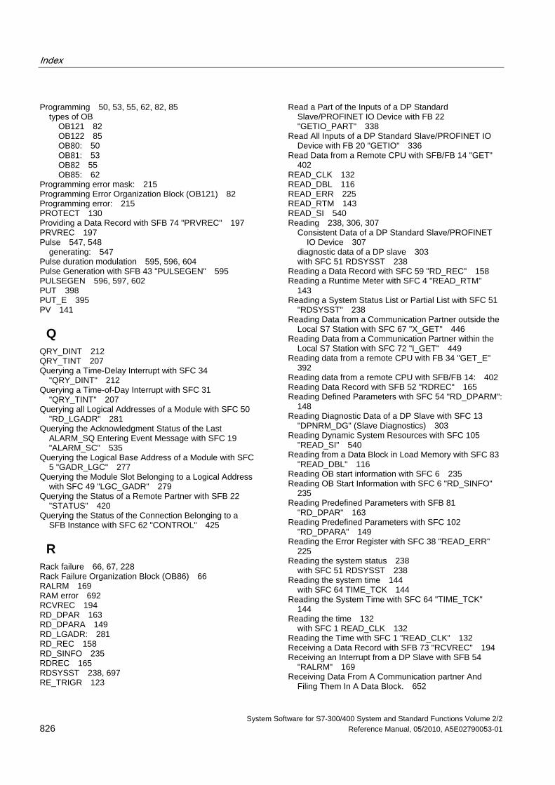
Index
System Software for S7-300/400 System and Standard Functions Volume 2/2 826 Reference Manual, 05/2010, A5E02790053-01
Programming 50, 53, 55, 62, 82, 85 types of OB
OB121 82 OB122 85 OB80: 50 OB81: 53 OB82 55 OB85: 62
Programming error mask: 215 Programming Error Organization Block (OB121) 82 Programming error: 215 PROTECT 130 Providing a Data Record with SFB 74 "PRVREC" 197 PRVREC 197 Pulse 547, 548
generating: 547 Pulse duration modulation 595, 596, 604 Pulse Generation with SFB 43 "PULSEGEN" 595 PULSEGEN 596, 597, 602 PUT 398 PUT_E 395 PV 141
Q QRY_DINT 212 QRY_TINT 207 Querying a Time-Delay Interrupt with SFC 34
"QRY_DINT" 212 Querying a Time-of-Day Interrupt with SFC 31
"QRY_TINT" 207 Querying all Logical Addresses of a Module with SFC 50
"RD_LGADR" 281 Querying the Acknowledgment Status of the Last
ALARM_SQ Entering Event Message with SFC 19 "ALARM_SC" 535
Querying the Logical Base Address of a Module with SFC 5 "GADR_LGC" 277
Querying the Module Slot Belonging to a Logical Address with SFC 49 "LGC_GADR" 279
Querying the Status of a Remote Partner with SFB 22 "STATUS" 420
Querying the Status of the Connection Belonging to a SFB Instance with SFC 62 "CONTROL" 425
R Rack failure 66, 67, 228 Rack Failure Organization Block (OB86) 66 RALRM 169 RAM error 692 RCVREC 194 RD_DPAR 163 RD_DPARA 149 RD_LGADR: 281 RD_REC 158 RD_SINFO 235 RDREC 165 RDSYSST 238, 697 RE_TRIGR 123
Read a Part of the Inputs of a DP Standard Slave/PROFINET IO Device with FB 22 "GETIO_PART" 338
Read All Inputs of a DP Standard Slave/PROFINET IO Device with FB 20 "GETIO" 336
Read Data from a Remote CPU with SFB/FB 14 "GET" 402
READ_CLK 132 READ_DBL 116 READ_ERR 225 READ_RTM 143 READ_SI 540 Reading 238, 306, 307
Consistent Data of a DP Standard Slave/PROFINET IO Device 307
diagnostic data of a DP slave 303 with SFC 51 RDSYSST 238
Reading a Data Record with SFC 59 "RD_REC" 158 Reading a Runtime Meter with SFC 4 "READ_RTM"
143 Reading a System Status List or Partial List with SFC 51
"RDSYSST" 238 Reading Data from a Communication Partner outside the
Local S7 Station with SFC 67 "X_GET" 446 Reading Data from a Communication Partner within the
Local S7 Station with SFC 72 "I_GET" 449 Reading data from a remote CPU with FB 34 "GET_E"
392 Reading data from a remote CPU with SFB/FB 14: 402 Reading Data Record with SFB 52 "RDREC" 165 Reading Defined Parameters with SFC 54 "RD_DPARM":
148 Reading Diagnostic Data of a DP Slave with SFC 13
"DPNRM_DG" (Slave Diagnostics) 303 Reading Dynamic System Resources with SFC 105
"READ_SI" 540 Reading from a Data Block in Load Memory with SFC 83
"READ_DBL" 116 Reading OB start information with SFC 6 235 Reading OB Start Information with SFC 6 "RD_SINFO"
235 Reading Predefined Parameters with SFB 81
"RD_DPAR" 163 Reading Predefined Parameters with SFC 102
"RD_DPARA" 149 Reading the Error Register with SFC 38 "READ_ERR"
225 Reading the system status 238
with SFC 51 RDSYSST 238 Reading the system time 144
with SFC 64 TIME_TCK 144 Reading the System Time with SFC 64 "TIME_TCK"
144 Reading the time 132
with SFC 1 READ_CLK 132 Reading the Time with SFC 1 "READ_CLK" 132 Receiving a Data Record with SFB 73 "RCVREC" 194 Receiving an Interrupt from a DP Slave with SFB 54
"RALRM" 169 Receiving Data From A Communication partner And
Filing Them In A Data Block. 652
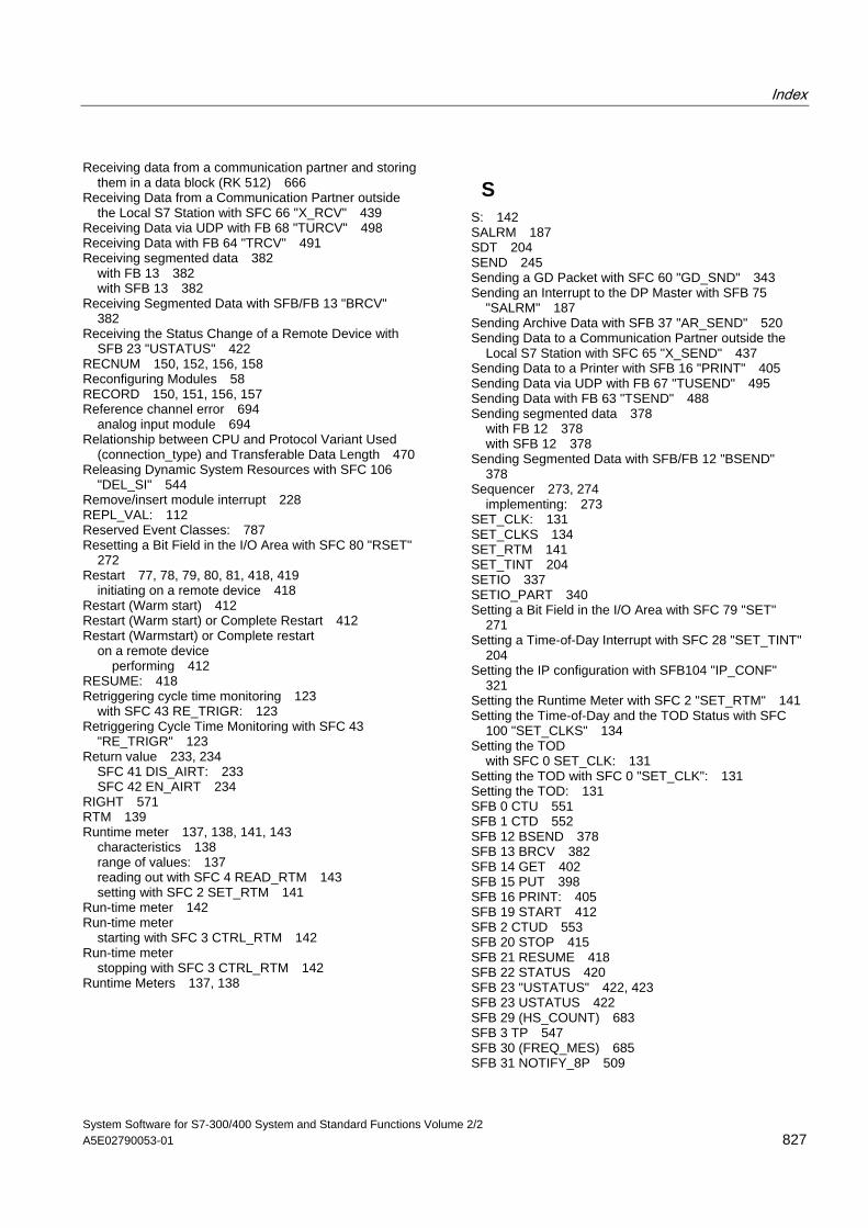
Index
System Software for S7-300/400 System and Standard Functions Volume 2/2 A5E02790053-01 827
Receiving data from a communication partner and storing them in a data block (RK 512) 666
Receiving Data from a Communication Partner outside the Local S7 Station with SFC 66 "X_RCV" 439
Receiving Data via UDP with FB 68 "TURCV" 498 Receiving Data with FB 64 "TRCV" 491 Receiving segmented data 382
with FB 13 382 with SFB 13 382
Receiving Segmented Data with SFB/FB 13 "BRCV" 382
Receiving the Status Change of a Remote Device with SFB 23 "USTATUS" 422
RECNUM 150, 152, 156, 158 Reconfiguring Modules 58 RECORD 150, 151, 156, 157 Reference channel error 694
analog input module 694 Relationship between CPU and Protocol Variant Used
(connection_type) and Transferable Data Length 470 Releasing Dynamic System Resources with SFC 106
"DEL_SI" 544 Remove/insert module interrupt 228 REPL_VAL: 112 Reserved Event Classes: 787 Resetting a Bit Field in the I/O Area with SFC 80 "RSET"
272 Restart 77, 78, 79, 80, 81, 418, 419
initiating on a remote device 418 Restart (Warm start) 412 Restart (Warm start) or Complete Restart 412 Restart (Warmstart) or Complete restart
on a remote device performing 412
RESUME: 418 Retriggering cycle time monitoring 123
with SFC 43 RE_TRIGR: 123 Retriggering Cycle Time Monitoring with SFC 43
"RE_TRIGR" 123 Return value 233, 234
SFC 41 DIS_AIRT: 233 SFC 42 EN_AIRT 234
RIGHT 571 RTM 139 Runtime meter 137, 138, 141, 143
characteristics 138 range of values: 137 reading out with SFC 4 READ_RTM 143 setting with SFC 2 SET_RTM 141
Run-time meter 142 Run-time meter
starting with SFC 3 CTRL_RTM 142 Run-time meter
stopping with SFC 3 CTRL_RTM 142 Runtime Meters 137, 138
S S: 142 SALRM 187 SDT 204 SEND 245 Sending a GD Packet with SFC 60 "GD_SND" 343 Sending an Interrupt to the DP Master with SFB 75
"SALRM" 187 Sending Archive Data with SFB 37 "AR_SEND" 520 Sending Data to a Communication Partner outside the
Local S7 Station with SFC 65 "X_SEND" 437 Sending Data to a Printer with SFB 16 "PRINT" 405 Sending Data via UDP with FB 67 "TUSEND" 495 Sending Data with FB 63 "TSEND" 488 Sending segmented data 378
with FB 12 378 with SFB 12 378
Sending Segmented Data with SFB/FB 12 "BSEND" 378
Sequencer 273, 274 implementing: 273
SET_CLK: 131 SET_CLKS 134 SET_RTM 141 SET_TINT 204 SETIO 337 SETIO_PART 340 Setting a Bit Field in the I/O Area with SFC 79 "SET"
271 Setting a Time-of-Day Interrupt with SFC 28 "SET_TINT"
204 Setting the IP configuration with SFB104 "IP_CONF"
321 Setting the Runtime Meter with SFC 2 "SET_RTM" 141 Setting the Time-of-Day and the TOD Status with SFC
100 "SET_CLKS" 134 Setting the TOD
with SFC 0 SET_CLK: 131 Setting the TOD with SFC 0 "SET_CLK": 131 Setting the TOD: 131 SFB 0 CTU 551 SFB 1 CTD 552 SFB 12 BSEND 378 SFB 13 BRCV 382 SFB 14 GET 402 SFB 15 PUT 398 SFB 16 PRINT: 405 SFB 19 START 412 SFB 2 CTUD 553 SFB 20 STOP 415 SFB 21 RESUME 418 SFB 22 STATUS 420 SFB 23 "USTATUS" 422, 423 SFB 23 USTATUS 422 SFB 29 (HS_COUNT) 683 SFB 3 TP 547 SFB 30 (FREQ_MES) 685 SFB 31 NOTIFY_8P 509
Index
System Software for S7-300/400 System and Standard Functions Volume 2/2 828 Reference Manual, 05/2010, A5E02790053-01
SFB 32 DRUM 273 SFB 33 ALARM 512 SFB 34 ALARM_8 518 SFB 35 ALARM_8P 515 SFB 36 NOTIFY 507 SFB 37 AR_SEND 520 SFB 38 (HSC_A_B): 686 SFB 39 (POS): 687 SFB 4 TON 549 SFB 41 CONT_C 581 SFB 42 CONT_S 589 SFB 43 PULSEGEN 595
automatic synchronization 598 three-step control 599, 601, 603, 604, 605 three-step control asymmetrical 601 two-step control: 595
SFB 44 619 SFB 46 632 SFB 47 639 SFB 48 644 SFB 49 648 SFB 5 TOF 550 SFB 52 RDREC 165 SFB 53 WRREC 167 SFB 54 RALRM 169 SFB 60 649, 671
Additional Error Information 671 SFB 61 652, 671
Additional Error Information 671 SFB 62 655, 671
Additional Error Information 671 SFB 63 657, 671
Additional Error Information 671 SFB 64 661, 671
Additional Error Information 671 SFB 65 666, 671
Additional Error Information 671 SFB 73 RCVREC 194 SFB 74 PRVREC 197 SFB 75 SALRM 187 SFB 8 USEND 370 SFB 81 163 SFB 9 URCV 374 SFB ANALOG 609 SFB COUNT 636 SFB DIGITAL 623 SFB FETCH RK 661 SFB FREQUENC 641 SFB PULSE 646 SFB RCV_PTP 652 SFB RES_RCVB 655 SFB SEND_PTP 649, 657 SFB SERVE_RK 666, 667 SFB104 IP_CONF 321 SFBs 362, 363, 366, 367, 368, 425
parameter classification 361 querying the status of a connection belonging to an
SFB instance 425 reaction to startup 366 reactions to errors and faults 368
SFC 0 SET_CLK: 131
SFC 1 READ_CLK 132 parameters 132
SFC 10 DIS_MSG 523 SFC 100 SET_CLKS 134 SFC 101 RTM 139 SFC 102 RD_DPARA 149 SFC 103 DP_TOPOL 259 SFC 104 CiR 126 SFC 105 READ_SI 540 SFC 106 DEL_SI 544 SFC 107 ALARM_DQ 537 SFC 108 ALARM_D 537 SFC 109 "PROTECT" 128 SFC 11 DPSYC_FR 290 SFC 112 "PN_IN" 313, 316
Background Information 313 SFC 113 "PN_OUT" 313, 317
Background Information 313 SFC 114 "PN_DP" 313, 318
Background Information 313 SFC 12 D_ACT_DP 296 SFC 126 SYNC_PI 267 SFC 127 SYNC_PO 269 SFC 13 DPNRM_DG 303 SFC 14 DPRD_DAT 307 SFC 15 DPWR_DAT 310 SFC 17 ALARM_SQ 532 SFC 18 ALARM_S 532 SFC 19 ALARM_SC: 535 SFC 2 SET_RTM 141 SFC 20 BLKMOV 97 SFC 21 FILL 102 SFC 22 CREAT_DB 105
error information 105 SFC 22 CREATE_DB 105 SFC 23 DEL_DB 107
error information 107 SFC 25 COMPRESS 110 SFC 26 UPDAT_PI 263 SFC 27 UPDAT_PO 265 SFC 28 SET_TINT 204 SFC 29 CAN_TINT 205 SFC 3 CTRL_RTM 142 SFC 30 ACT_TINT 206 SFC 31 QRY_TINT 207 SFC 32 SRT_DINT 211 SFC 33 CAN_DINT 214 SFC 34 QRY_DINT 212
error information 212 SFC 35 MP_ALM 125 SFC 36 MSK_FLT 223 SFC 37 DMSK_FLT 224 SFC 38 READ_ERR 225 SFC 39 DIS_IRT 229 SFC 4 READ_RTM 143 SFC 40 EN_IRT 231
error information 231 SFC 41 DIS_AIRT 233
return value 233
Index
System Software for S7-300/400 System and Standard Functions Volume 2/2 A5E02790053-01 829
SFC 42 EN_AIRT 234 error information 234 return value 234
SFC 43 RE_TRIGR 123 SFC 44 REPL_VAL 112 SFC 46 STP 123 SFC 46 TIME_TCK 144 SFC 47 WAIT 124 SFC 48 SNC_RTCB 133 SFC 49 LGC_GADR 279 SFC 5 GADR_LGC 277 SFC 50 RD_LGADR 281 SFC 51 RDSYSST 238, 697 SFC 52 WR_USRMSG 245 SFC 55 WR_PARM 150 SFC 56 WR_DPARM 152 SFC 57 PARM_MOD 153 SFC 58 WR_REC 156
parameters 156 SFC 59 RD_REC 158 SFC 6 RD_SINFO 235 SFC 60 GD_SND 343 SFC 61 GD_RCV 346 SFC 62 CONTROL 425 SFC 63 (AB_CALL) 689 SFC 64 TIME_TICK 144
parameters 144 SFC 65 X_SEND 437 SFC 66 X_RCV 439 SFC 67 X_GET 446 SFC 68 X_PUT 444 SFC 69 X_ABORT 448 SFC 7 DP_PRAL: 287 SFC 70 282 SFC 71 284 SFC 72 I_GET 449 SFC 73 I_PUT 451 SFC 74 I_ABORT 453 SFC 78 "OB_RT" 249 SFC 79 SET 271 SFC 80 RSET 272 SFC 82 CREA_DBL 113 SFC 83 READ_DBL 116 SFC 84 WRIT_DBL 118 SFC 85 CREA_DB 120 SFC 87 C_DIAG 254 SFC 9 EN_MSG 525 SFC 90 H_CTRL 679 SFC99 319, 320 Shadow Memory 313, 314 SIGN: 211 Slave clocks 133
synchronization of: 133 SNC_RTCB 133 SRCBLK 97 SRT_DINT 211 SSL ID W#16#xy25 - Assignment of Process Image
Partitions to OBs 719 SSL_HEADER: 238 SSL-ID 700
SSL-ID W#16#00B1 - Module Diagnostic Information 762
SSL-ID W#16#00B2 - Diagnostic Data Record 1 with Physical Address 764
SSL-ID W#16#00B3 - Module Diagnostic Data with Logical Base Address 765
SSL-ID W#16#00B4 - Diagnostic Data of a DP Slave: 766
SSL-ID W#16#0x75 - Switched DP Slaves in the H System 735
SSL-ID W#16#0x94 - Status Information for Rack/Station 749
SSL-ID W#16#xy11 - Module Identification 702 SSL-ID W#16#xy12 - CPU Characteristics 703 SSL-ID W#16#xy13 - Memory Areas 706 SSL-ID W#16#xy14 - System Areas 708 SSL-ID W#16#xy15 - Block Types 710 SSL-ID W#16#xy1C - Component Identification 711 SSL-ID W#16#xy22 - Interrupt Status 716 SSL-ID W#16#xy32 - Communication Status Data 722 SSL-ID W#16#xy71 - H CPU Group Information: 729 SSL-ID W#16#xy74 - Status of the Module LEDs 732 SSL-ID W#16#xy90 - DP Master System Information
737 SSL-ID W#16#xy91 - Module Status Information 739 SSL-ID W#16#xy92 - Rack / Station Status Information:
745 SSL-ID W#16#xy95 - Extended DP Master System
Information 751 SSL-ID W#16#xy96 - PROFINET IO and PROFIBUS DP
Module Status Information 753 SSL-ID W#16#xy9C - Tool changer information
(PROFINET IO) 756 SSL-ID W#16#xyA0 - Diagnostic Buffer 760 Standard OB events: 768 Standard user events: 785 START 412, 413 Starting a Time-Delay Interrupt with SFC 32 "SRT_DINT"
211 Starting and Stopping a Runtime Meter with SFC 3
"CTRL_RTM" 142 Startup 77, 78, 79, 80, 81 Startup Behavior of the SFBs for Generating
Block-Related Messages: 527 Startup Organization Blocks (OB100
OB101 and OB102) 77 Startup Routine of SFBs for Configured S7 Connections
366 STATUS 207, 212, 420, 421 Status Interrupt 28 Status Interrupt OB (OB55) 28 Status of a connection S7-300 428 Status of a remote partner 420
querying: 420 STEP 7 50, 53, 55, 62, 63, 82, 85
types of OB OB121 82 OB122 85 OB80 50 OB81 53 OB82 55
Index
System Software for S7-300/400 System and Standard Functions Volume 2/2 830 Reference Manual, 05/2010, A5E02790053-01
OB85 62 Step Control with SFB 42/FB 42 "CONT_S" 589 STOP 415, 417
changing a remote device to: 415 Stop events 776 STP 123 Structure of a Partial SSL List: 699 Structure of Channel-Specific Diagnostic Data 694 Substitute value 112
writing to ACCU 1 with SFC 44 REPL_VAL 112 Switched DP Slaves 735 SYNC_PI 267 SYNC_PO 269 Synchronization
Clock: 131 Synchronization: 131 Synchronizing Groups of DP Slaves with SFC 11
"DPSYC_FR" 290 Synchronizing Slave Clocks with SFC 48 "SNC_RTCB"
133 Synchronous Cycle Interrupt OBs (OB61 to OB64) 42 Synchronous error
Masking: 215 Unmasking: 215
Synchronous error: 215 Synchronous errors 82, 85, 223, 224
masking with SFC 36 MSK_FLT 223 OB121 82 OB122 85 unmasking with SFC 37 DMSK_FLT 224
Synchronous errors: 769 System areas: 708 System data 697 System Diagnostics: 235 System status list 697, 701
partial lists: 701
T TCON 484 TDISCON 486 Technical Data of the IEC Functions 557 Technology Synchronization Interrupt OB (OB65) 43 Temporary variables (TEMP) 85
required for OBs: 85 Terminating a Connection with FB 66 "TDISCON" 486 Testing a Data Block with SFC 24 "TEST_DB": 109 Time error 228 Time Error Organization Block (OB80) 50 TIME_TCK 144 Time-delay interrupt 209, 210, 211, 212, 214, 227
canceling with SFC 33 CAN_DINT 214 conditions for the call 209 querying with SFC 34 QRY_DINT 212 situations affecting 209 starting in the startup OB 209 starting with SFC 32 SRT_DINT 211
Time-delay interrupt OBs (OB20 to OB23) 22 Time-delay interrupts 22
Time-of-day interrupt 201, 202, 203, 204, 205, 206, 207, 227 activating with SFC 30 ACT_TINT 206 canceling with SFC 29 CAN_TINT 205 cold restart 202 conditions for the call: 201 execution and reaction: 202 OB 201 querying with SFC 31 QRY_TINT 207 setting with SFC 28 SET_TINT 204 situations affecting 202 warm restart 202
Time-of-day interrupt OBs (OB10 to OB17) 18 Time-Of-Day: 131 Timer number error: 215 TOF 550 TON 549 TP 547 Transferring a Substitute Value to Accumulator 1 with
SFC 44 "REPL_VAL" 112 Transferring parameters 150, 152
with SFC 55 WR_PARM 150 with SFC 56 WR_DPARM 152
Transmitting the entire range or a section of a data block to a communication partner 649, 657
Transmitting the entire range or a section of a data block to a communication partner (RK 512) 661
TRCV 491 Triggering a Hardware Interrupt on the DP Master with
SFC 7 "DP_PRAL" 287 Triggering a Multicomputing Interrupt with SFC 35
"MP_ALM" 125 TSEND 488 TURCV 498 TUSEND 495 Type ID 700
of a module: 700
U Uncoordinated receiving of data 374
with FB 9 374 with SFB 9 374
Uncoordinated Receiving of Data with SFB/FB 9 "URCV" 374
Uncoordinated Reception of Data with FB29 "URCV_E" 389
Uncoordinated sending of data 370 with FB 8 370 with SFB 8 370
Uncoordinated sending of data with FB28 "USEND_E" 386
Uncoordinated Sending of Data with SFB 8/FB 8 "USEND" 370
Uninterruptible Copying of Variables with SFC 81 "UBLKMOV": 100
Unmasking Errors: 215
Unmasking Synchronous Errors with SFC 37 "DMSK_FLT" 224
Index
System Software for S7-300/400 System and Standard Functions Volume 2/2 A5E02790053-01 831
Unmasking: 215 Up / Down Count with SFB 2 "CTUD" 553 Up / down count: 553 UP_LIMIT 105 UPDAT_PI: 263 UPDAT_PO: 265 Update Interrupt 32 Update Interrupt OB (OB56) 32 Updating DP Interconnections 318 Updating the Outputs of the PROFINET Interface of the
PROFINET CBA Component 317 Updating the process image input table 263 Updating the Process Image Input Table with SFC 26
"UPDAT_PI" 263 Updating the process image output table 265 Updating the Process Image Output Table with SFC 27
"UPDAT_PO" 265 Updating the Process Image Partition Input Table in a
Synchronous Cycle with SFC 126 "SYNC_PI" 267 Updating the Process Image Partition in a Synchronous
Cycle with SFC 127 "SYNC_PO" 269 URCV 374 URCV_E 389 USEND 370 USEND_E 386 User information 692 User memory 110
compressing with SFC 25 110 USTATUS 422
V Variable declaration table 50, 82, 85
for OB121 82 for OB122 85 for OB80 50
W WAIT 124 Wire break 694, 695
analog input module 694 analog output module 694
WR_DPARM 152 WR_PARM 150
WR_REC 156 WR_USRMSG 245 WRIT_DBL 118 Write a Part of the Outputs of a DP Standard
Slave/PROFINET IO Device with FB 23 "SETIO_PART" 340
Write All Outputs of a DP Standard Slave/PROFINET IO Device with FB 21 "SETIO" 337
Write error Data block: 215
Write error instance data block: 215 Write error: 215 Writing a Data Block In Load Memory with SFC 84
"WRIT_DBL" 118 Writing a Data Record with SFB 53 "WRREC" 167 Writing a Data Record with SFC 58 "WR_REC" 156 Writing a User-Defined Diagnostic Event to the
Diagnostic Buffer with SFC 52 "WR_USMSG" 245 Writing and Reading Data Records 145 Writing Consistent Data to a DP Standard
Slave/PROFINET IO Device with SFC 15 "DPWR_DAT" 310
Writing Data to a Communication Partner outside the Local S7 Station with SFC 68 "X_PUT" 444
Writing Data to a Communication Partner within the Local S7 Station with SFC 73 "I_PUT" 451
Writing data to a remote CPU with FB 35 "PUT_E" 395 Writing data to a remote CPU with SFB/FB 15 398 Writing Data to a Remote CPU with SFB/FB 15 "PUT"
398 Writing Default Parameters with SFC 56 "WR_DPARM"
152 Writing Dynamic Parameters with SFC 55 "WR_PARM"
150 WRREC 167 WT 124 WWW 319
X X_ABORT: 448 X_GET: 446 X_PUT: 444 X_RCV: 439 X_SEND: 437

Index
System Software for S7-300/400 System and Standard Functions Volume 2/2 832 Reference Manual, 05/2010, A5E02790053-01