Embed Size (px)
Citation preview
T 3967 EN
SAMSON AKTIENGESELLSCHAFT · Weismüllerstraße 3 · 60314 Frankfurt am Main, Germany Phone: +49 69 4009-0 · Fax: +49 69 4009-1507 · [email protected] · www.samson.de
Type 3967 Solenoid Valve
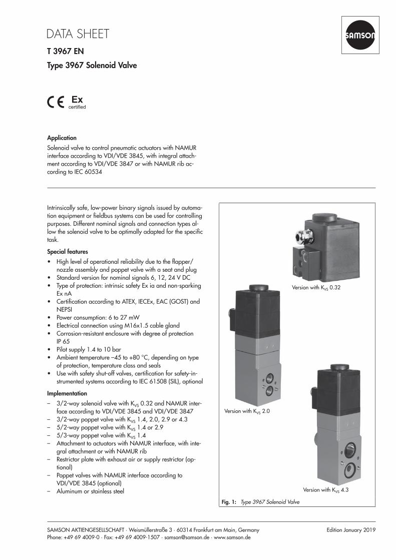
ApplicationSolenoid valve to control pneumatic actuators with NAMUR interface according to VDI/VDE 3845, with integral attach-ment according to VDI/VDE 3847 or with NAMUR rib ac-cording to IEC 60534
Edition January 2019
Version with KVS 0.32
Version with KVS 2.0
Version with KVS 4.3
Fig. 1: Type 3967 Solenoid Valve
Intrinsically safe, low-power binary signals issued by automa-tion equipment or fieldbus systems can be used for controlling purposes. Different nominal signals and connection types al-low the solenoid valve to be optimally adapted for the specific task.
Special features • High level of operational reliability due to the flapper/
nozzle assembly and poppet valve with a seat and plug • Standard version for nominal signals 6, 12, 24 V DC • Type of protection: intrinsic safety Ex ia and non-sparking
Ex nA • Certification according to ATEX, IECEx, EAC (GOST) and
NEPSI • Power consumption: 6 to 27 mW • Electrical connection using M16x1.5 cable gland • Corrosion-resistant enclosure with degree of protection
IP 65 • Pilot supply 1.4 to 10 bar • Ambient temperature –45 to +80 °C, depending on type
of protection, temperature class and seals • Use with safety shut-off valves, certification for safety-in-
strumented systems according to IEC 61508 (SIL), optional
Implementation – 3/2-way solenoid valve with KVS 0.32 and NAMUR inter-
face according to VDI/VDE 3845 and VDI/VDE 3847 – 3/2-way poppet valve with KVS 1.4, 2.0, 2.9 or 4.3 – 5/2-way poppet valve with KVS 1.4 or 2.9 – 5/3-way poppet valve with KVS 1.4 – Attachment to actuators with NAMUR interface, with inte-
gral attachment or with NAMUR rib – Restrictor plate with exhaust air or supply restrictor (op-
tional) – Poppet valves with NAMUR interface according to
VDI/VDE 3845 (optional) – Aluminum or stainless steel
2 T 3967 EN
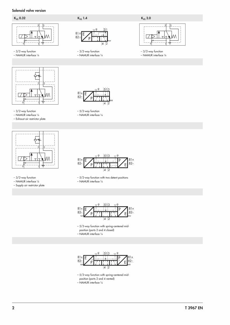
Solenoid valve version
KVS 0.32 KVS 1.4 KVS 2.0
3
1
2
9
EP
39
4
1
2
3
1
2
9
– 3/2-way function – NAMUR interface ¼
– 3/2-way function – NAMUR interface ¼
– 3/2-way function – NAMUR interface ¼
3
1
2
9
81+82–
EP
39 5
4
1
2
– 3/2-way function – NAMUR interface ¼ – Exhaust air restrictor plate
– 5/2-way function – NAMUR interface ¼
3
1
2
9
81+ 81+82– 82–
EP
39 95
4
1
2
PE
– 3/2-way function – NAMUR interface ¼ – Supply air restrictor plate
– 5/2-way function with two detent positions – NAMUR interface ¼
81+ 81+82– 82–
EP
39 95
4
1
2
PE
– 5/3-way function with spring-centered mid-position (ports 2 and 4 closed)
– NAMUR interface ¼
81+ 81+82– 82–
EP
39 95
4
1
2
PE
14 12
– 5/3-way function with spring-centered mid-position (ports 2 and 4 vented)
– NAMUR interface ¼
T 3967 EN 3
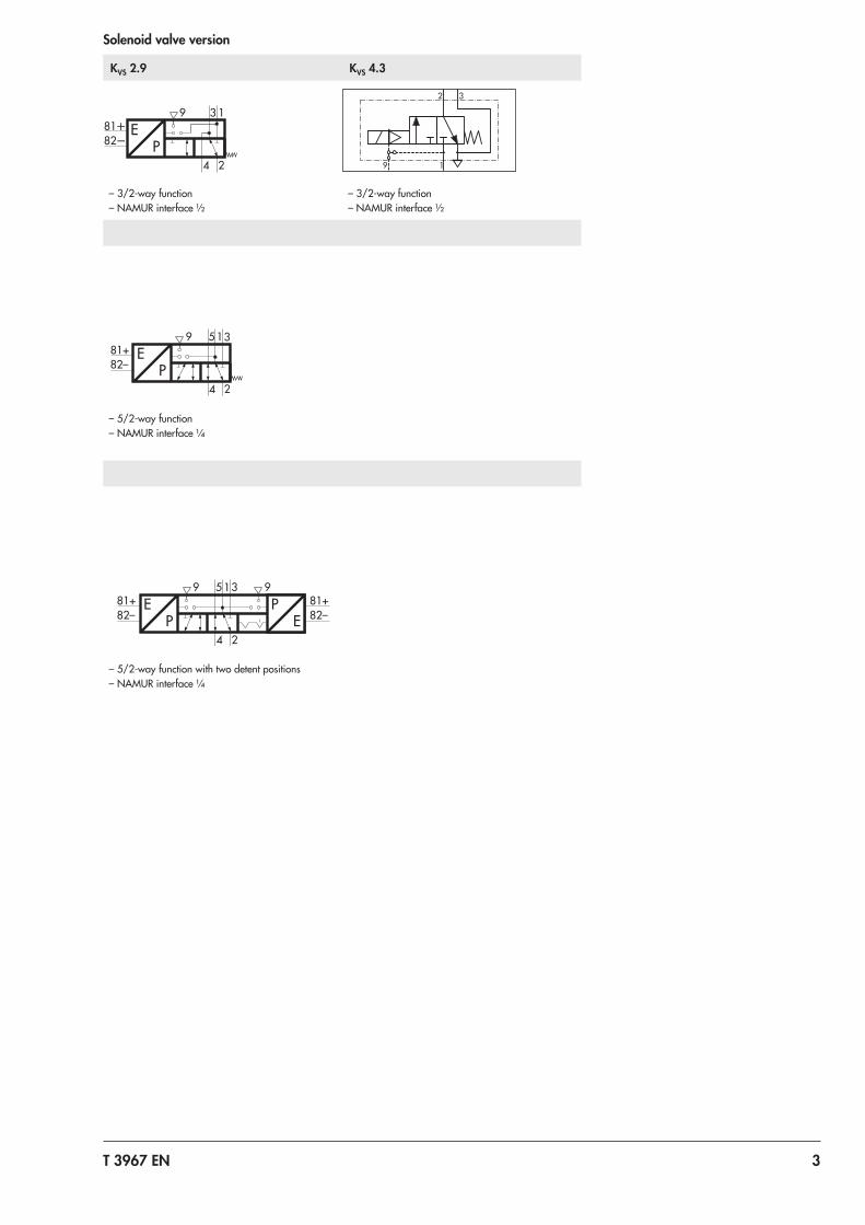
Solenoid valve version
KVS 2.9 KVS 4.3
EP
39
4
1
2
3
1
2
9
– 3/2-way function – NAMUR interface ½
– 3/2-way function – NAMUR interface ½
81+82–
EP
39 5
4
1
2
– 5/2-way function – NAMUR interface ¼
81+ 81+82– 82–
EP
39 95
4
1
2
PE
– 5/2-way function with two detent positions – NAMUR interface ¼
4 T 3967 EN
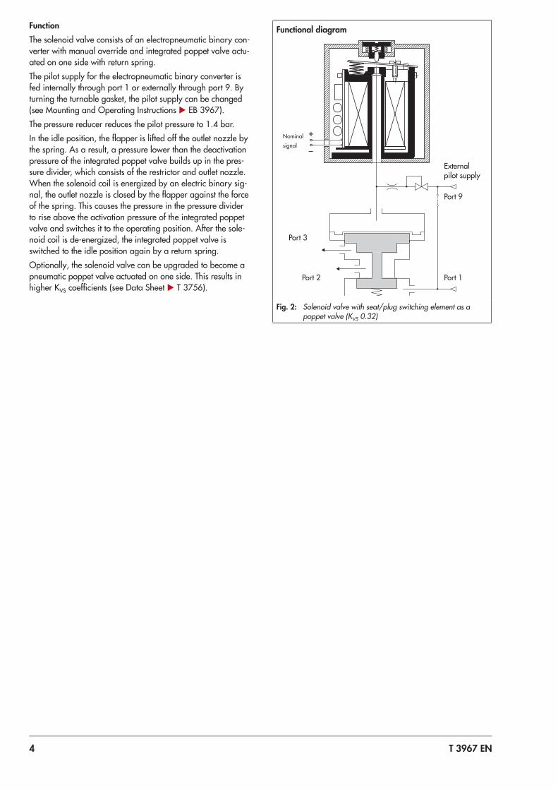
FunctionThe solenoid valve consists of an electropneumatic binary con-verter with manual override and integrated poppet valve actu-ated on one side with return spring.The pilot supply for the electropneumatic binary converter is fed internally through port 1 or externally through port 9. By turning the turnable gasket, the pilot supply can be changed (see Mounting and Operating Instructions u EB 3967).The pressure reducer reduces the pilot pressure to 1.4 bar.In the idle position, the flapper is lifted off the outlet nozzle by the spring. As a result, a pressure lower than the deactivation pressure of the integrated poppet valve builds up in the pres-sure divider, which consists of the restrictor and outlet nozzle. When the solenoid coil is energized by an electric binary sig-nal, the outlet nozzle is closed by the flapper against the force of the spring. This causes the pressure in the pressure divider to rise above the activation pressure of the integrated poppet valve and switches it to the operating position. After the sole-noid coil is de-energized, the integrated poppet valve is switched to the idle position again by a return spring.Optionally, the solenoid valve can be upgraded to become a pneumatic poppet valve actuated on one side. This results in higher KVS coefficients (see Data Sheet u T 3756).
Functional diagram
+
–
Fig. 2: Solenoid valve with seat/plug switching element as a poppet valve (KVS 0.32)
External pilot supply
Nominal signal
Port 9
Port 3
Port 2 Port 1
T 3967 EN 5
Technical data
General data
Design Solenoid with flapper/nozzle assembly and plug/seat valve with return spring
Degree of protection IP 65 with filter check valve
Compliance ˙
Material Enclosure Polyamide PA 6-3-T-GF35, black
Connecting plate
AlMgSiPb, powder coated, black or stainless steel 1.4404
Adapter plate AlMgSiPb, powder coated, gray beige RAL 1019 or stainless steel 1.4404
Screws Stainless steel A2-70
Springs Stainless steel 1.4310
Seals Silicone rubber
Ambient temperature See Electric data
Mounting position Any desired position
Electric data
Nominal signal UN 6 V DC 12 V DC 24 V DC
Umax 27 V 40 V 60 V
Switching point ON U80 °C ≥4.8 V ≥9.6 V ≥18 V
I20 °C ≥1.41 mA ≥1.52 mA ≥1.57 mA
P20 °C ≥5.47 mW ≥13.05 mW ≥26.71 mW
OFF U–25 °C ≤1.0 V ≤2.3 V ≤4.6 V
Input impedance R20 °C 2.6 kΩ 5.3 kΩ 10.5 kΩ
Temperature influence 0.4 %/°C 0.2 %/°C 0.1 %/°C
Type of protection 1) Intrinsic safety: II 2G Ex ia IIC T6 Gb / II 2D Ex ia IIIC T80°C Db
Non-sparking: II 3G Ex nA IIC T6 / II 3D Ex tD A21 IP65 T80°C
Output voltage 2) Ui (V) 32
Output current 2) Ii (mA) 150
Power dissipation 2) Pi (mW) 250 No restrictions
Outer inductance 2) Li Negligibly small
Outer capacitance 2) Ci Negligibly small
Ambient temperature 3) –45 to +60 °C (temperature class T6)
–45 to +70 °C (temperature class T5)
–45 to +80 °C (temperature class T4)
Connection Screw terminal, 2-pole, with cable gland M16x1.5
1) According to EC type examination certificate and statement of conformity2) Permissible maximum values when connected to a certified intrinsically safe circuit.3) The permissible ambient temperature depends on the permissible ambient temperature of the components, type of protection and temperature class.
6 T 3967 EN
Pneumatic data for solenoid valve with KVS 0.32, actuated on one side
Switching function 3/2-way function
KVS 1) 0.32
Safety approval SIL 2)
Compressed air quality according to ISO 8573-1
Max. particle size and density: Class 4 · Oil content: Class 3 · Pressure dew point: Class 3 or at least 10 K below the lowest ambient temperature to be expected
Pilot supply Medium Instrument air, free from corrosive substances and nitrogen
Pressure 3) 1.4 to 10 bar
Operating medium Instrument air, free from corrosive substances and nitrogen
Operating pressure Max. 10 bar
Air consumption ≤80 ln/h at 1.4 bar pilot supply in neutral position
≤25 ln/h at 1.4 bar pilot supply in operating position
Switching time ≤65 ms
Connection G ¼ or ¼ NPT and NAMUR interface ¼ 4)
Weight 0.45 kg
0.80 kg (with adapter plate)
1) The air flow rate when p1 = 2.4 bar and p2 = 1.0 bar is calculated using the following formula: Q = KVS x 36.22 in m³/h.
2) SIL according to IEC 615083) When using the solenoid valve with an operating pressure of 10 bar, a minimum pilot pressure of 1.9 bar is required.4) NAMUR interface according to VDI/VDE 3845 and VDI/VDE 3847
Poppet valve with NAMUR interface, KVS 1.4 or 2.9, actuated on one side
Switching function 3/2-way function with exhaust air feedback 5/2-way function
KVS 1) 1.4 or 2.9
Safety approval – –
Design Spool, metal-to-metal seat, zero overlap, with return spring
Material Enclosure Aluminum, powder coated, gray-beige RAL 1019 1.4404 (see Versions and ordering data for special versions)
Seals Silicone
Filter Polyethylene
Screws 1.4571
Actuation Type 3797 Solenoid Valve
Operating medium Instrument air (free from corrosive substances) or nitrogen, air containing oil or non-corrosive gases
Compressed air quality according to ISO 8573-1
Max. particle size and density: Class 4 · Oil content: Class 3 · Pressure dew point: Class 3 or at least 10 K below the lowest ambient temperature to be expected
Max. operating pressure 10 bar
Ambient temperature 2) –45 to +80 °C
Switching cycles ≥2 x 10⁷
Connection KVS 1.4 G ¼ or ¼ NPT, NAMUR interface 3)
KVS 2.9 G ½ or ½ NPT, NAMUR interface 3)
Approx. weight KVS 1.4 485 g (standard version)
KVS 2.9 1760 g (standard version)
1) The air flow rate when p1 = 2.4 bar and p2 = 1.0 bar is calculated using the following formula: Q = KVS x 36.22 in m³/h.2) The permissible ambient temperature of the solenoid valve depends on the permissible ambient temperature of the components, type of protection and temperature
class.3) NAMUR interface according to VDI/VDE 3845
T 3967 EN 7
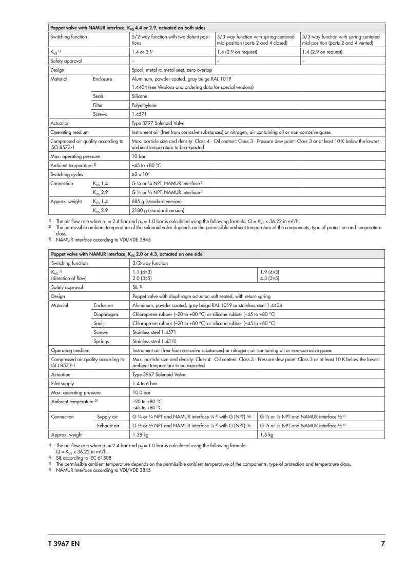
Poppet valve with NAMUR interface, KVS 4.4 or 2.9, actuated on both sides
Switching function 5/2-way function with two detent posi-tions
5/3-way function with spring-centered mid-position (ports 2 and 4 closed)
5/3-way function with spring-centered mid-position (ports 2 and 4 vented)
KVS 1) 1.4 or 2.9 1.4 (2.9 on request) 1.4 (2.9 on request)
Safety approval – – –
Design Spool, metal-to-metal seat, zero overlap
Material Enclosure Aluminum, powder coated, gray beige RAL 10191.4404 (see Versions and ordering data for special versions)
Seals Silicone
Filter Polyethylene
Screws 1.4571
Actuation Type 3797 Solenoid Valve
Operating medium Instrument air (free from corrosive substances) or nitrogen, air containing oil or non-corrosive gases
Compressed air quality according to ISO 8573-1
Max. particle size and density: Class 4 · Oil content: Class 3 · Pressure dew point: Class 3 or at least 10 K below the lowest ambient temperature to be expected
Max. operating pressure 10 bar
Ambient temperature 2) –45 to +80 °C
Switching cycles ≥2 x 10⁷
Connection KVS 1.4 G ¼ or ¼ NPT, NAMUR interface 3)
KVS 2.9 G ½ or ½ NPT, NAMUR interface 3)
Approx. weight KVS 1.4 685 g (standard version)
KVS 2.9 2180 g (standard version)
1) The air flow rate when p1 = 2.4 bar and p2 = 1.0 bar is calculated using the following formula: Q = KVS x 36.22 in m³/h.2) The permissible ambient temperature of the solenoid valve depends on the permissible ambient temperature of the components, type of protection and temperature
class.3) NAMUR interface according to VDI/VDE 3845
Poppet valve with NAMUR interface, KVS 2.0 or 4.3, actuated on one side
Switching function 3/2-way function
KVS 1) (direction of flow)
1.1 (4»3) 2.0 (3»5)
1.9 (4»3) 4.3 (3»5)
Safety approval SIL ²)
Design Poppet valve with diaphragm actuator, soft seated, with return spring
Material Enclosure Aluminum, powder coated, gray beige RAL 1019 or stainless steel 1.4404
Diaphragms Chloroprene rubber (–20 to +80 °C) or silicone rubber (–45 to +80 °C)
Seals Chloroprene rubber (–20 to +80 °C) or silicone rubber (–45 to +80 °C)
Screws Stainless steel 1.4571
Springs Stainless steel 1.4310
Operating medium Instrument air (free from corrosive substances) or nitrogen, air containing oil or non-corrosive gases
Compressed air quality according to ISO 8573-1
Max. particle size and density: Class 4 · Oil content: Class 3 · Pressure dew point: Class 3 or at least 10 K below the lowest ambient temperature to be expected
Actuation Type 3967 Solenoid Valve
Pilot supply 1.4 to 6 bar
Max. operating pressure 10.0 bar
Ambient temperature 3) –20 to +80 °C –45 to +80 °C
Connection Supply air G ¼ or ¼ NPT and NAMUR interface ¼ 4) with G (NPT) 3/8 G ½ or ½ NPT and NAMUR interface ½ 4)
Exhaust air G ½ or ½ NPT and NAMUR interface ¼ 4) with G (NPT) 3/8 G ½ or ½ NPT and NAMUR interface ½ 4)
Approx. weight 1.38 kg 1.5 kg
1) The air flow rate when p1 = 2.4 bar and p2 = 1.0 bar is calculated using the following formula: Q = KVS x 36.22 in m³/h.
2) SIL according to IEC 615083) The permissible ambient temperature depends on the permissible ambient temperature of the components, type of protection and temperature class.4) NAMUR interface according to VDI/VDE 3845
8 T 3967 EN
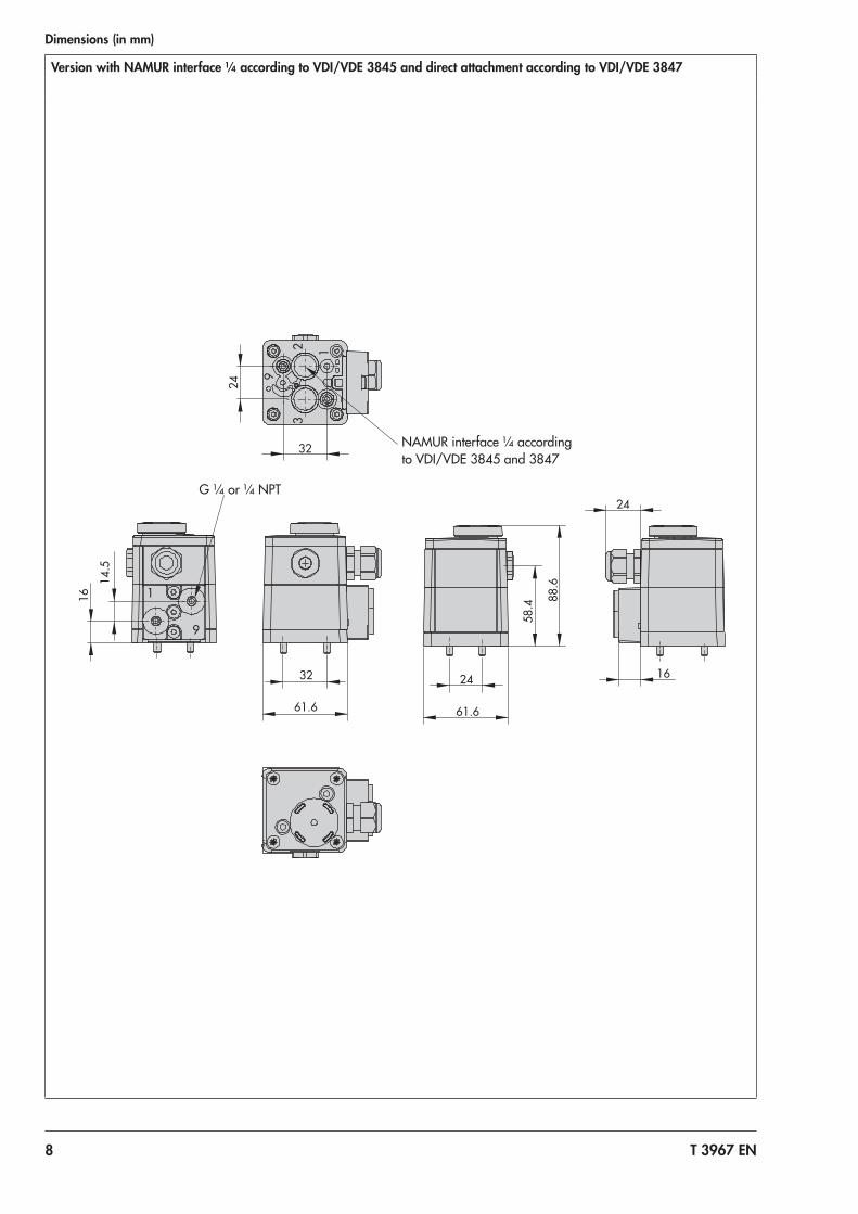
Dimensions (in mm)
Version with NAMUR interface ¼ according to VDI/VDE 3845 and direct attachment according to VDI/VDE 3847
61.6
32
24
16
88.
6
58.
4
32
24
61.6
24
16 1
4.5
9
23
1
1
9
NAMUR interface ¼ according to VDI/VDE 3845 and 3847
G ¼ or ¼ NPT
T 3967 EN 9
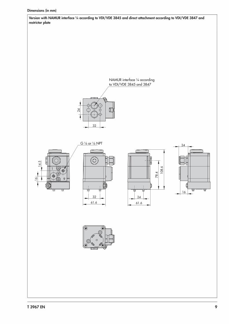
Dimensions (in mm)
Version with NAMUR interface ¼ according to VDI/VDE 3845 and direct attachment according to VDI/VDE 3847 and restrictor plate
G ¼ or ¼ NPT
NAMUR interface ¼ according to VDI/VDE 3845 and 3847
32
61.6
16
14.
5
108
.6
78.
4
24
61.6
16
24
24
32
1
9
10 T 3967 EN
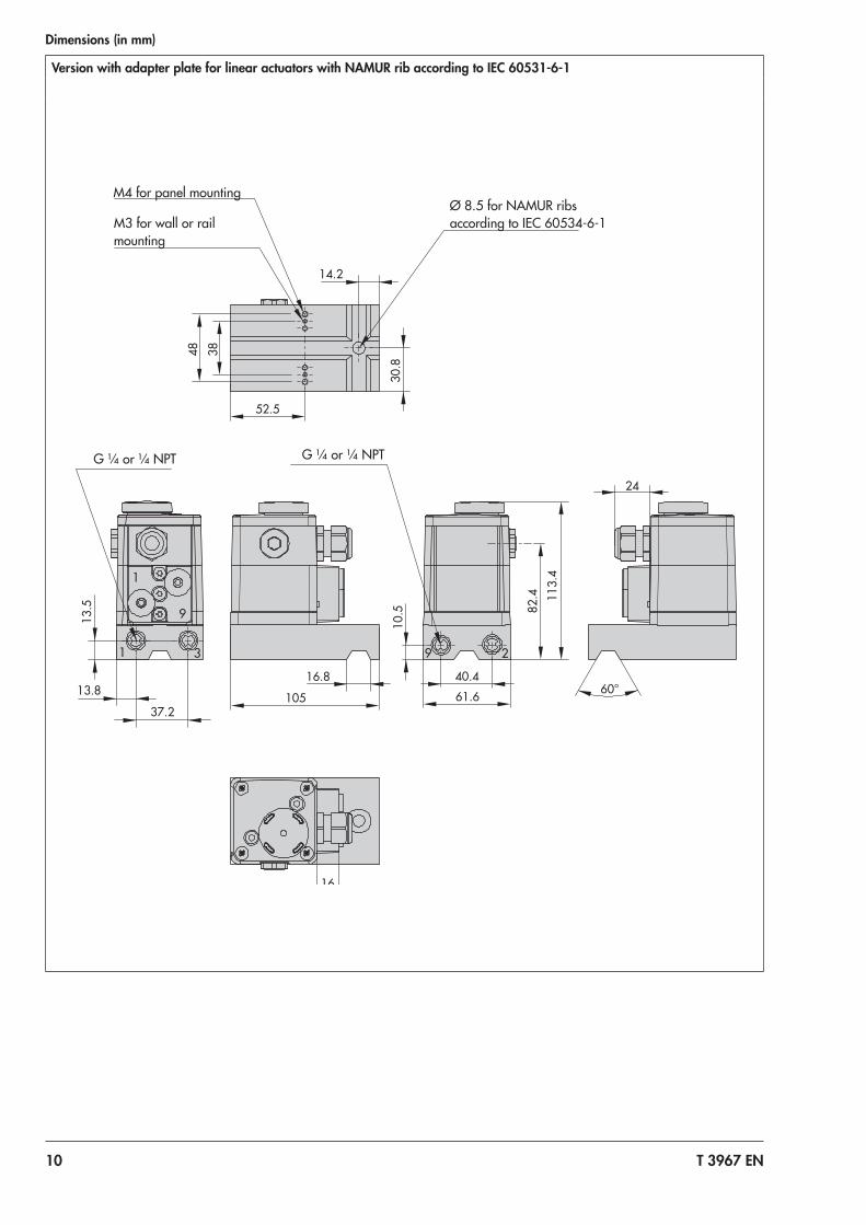
Dimensions (in mm)
Version with adapter plate for linear actuators with NAMUR rib according to IEC 60531-6-1
1
9
31 29
24
16
105
16.8
13.5
37.2
13.8
48
38
30.
8
14.2
82.
4
40.4
10.
5 113
.4
60° 61.6
52.5
G ¼ or ¼ NPT G ¼ or ¼ NPT
M4 for panel mounting
M3 for wall or rail mounting
Ø 8.5 for NAMUR ribs according to IEC 60534-6-1
T 3967 EN 11
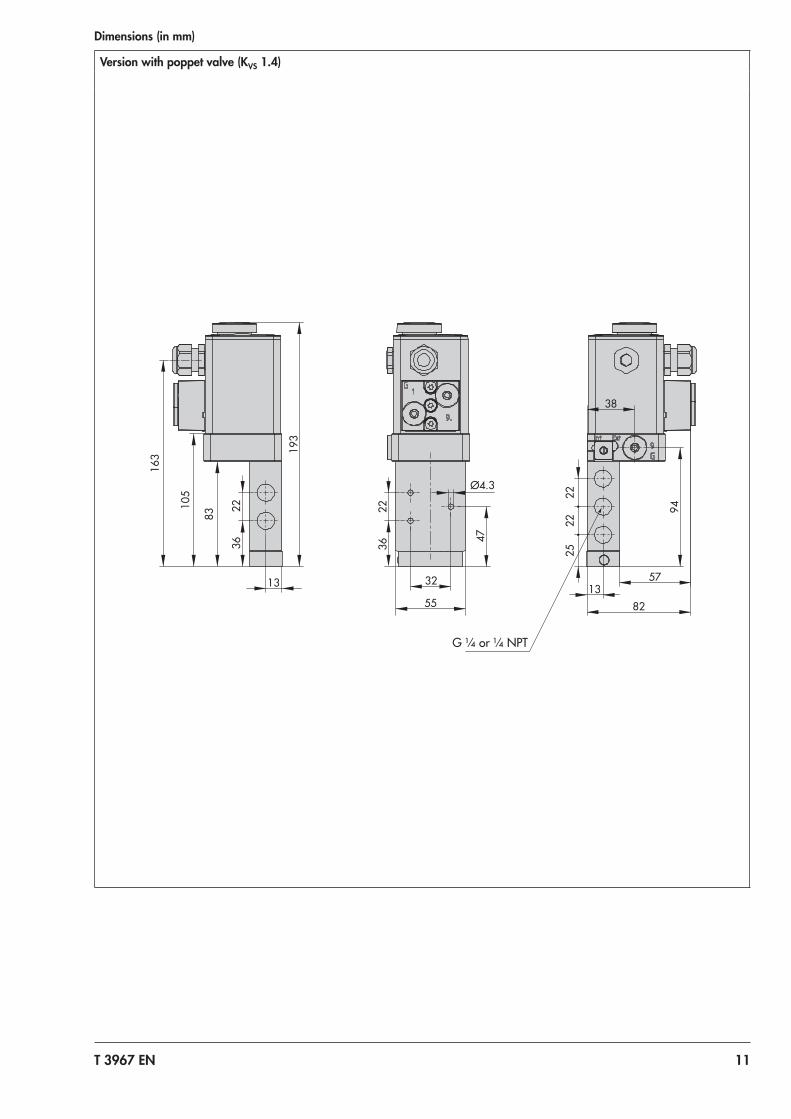
Dimensions (in mm)
Version with poppet valve (KVS 1.4)
32
36
22
47
Ø4.3
55
22
13
163
105
36
83
193
25
22
22
13 82
57
38
94
G ¼ or ¼ NPT
12 T 3967 EN
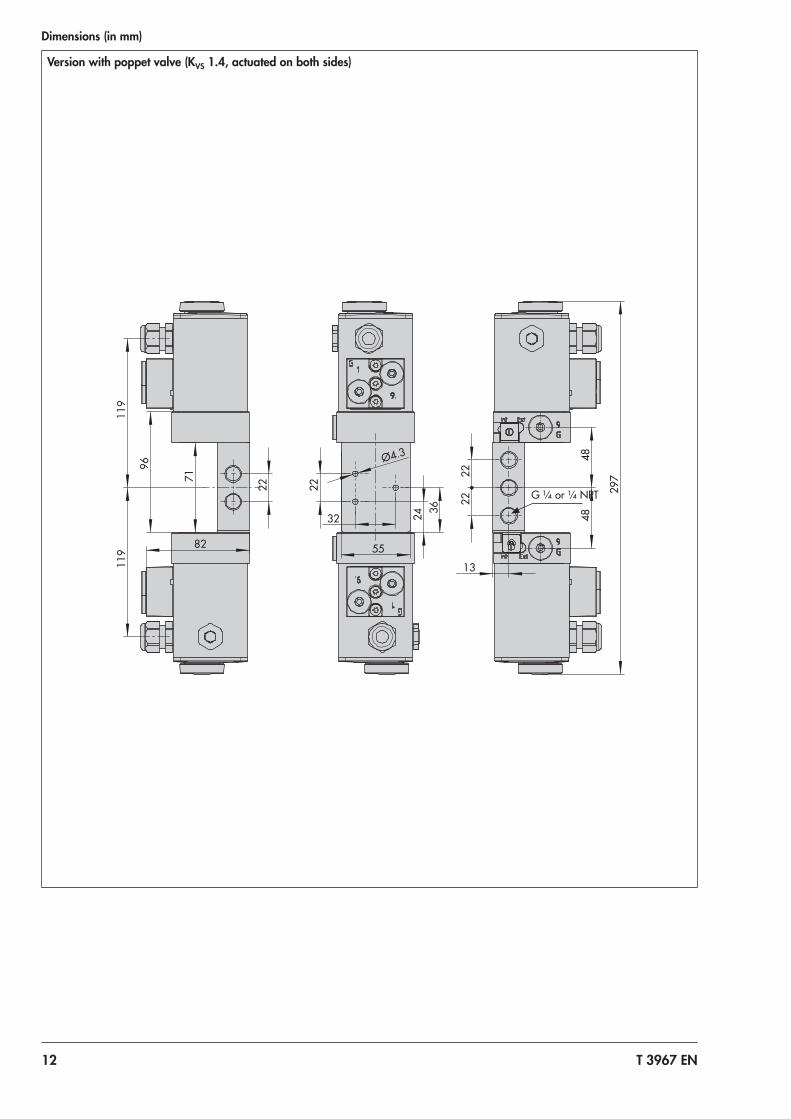
Dimensions (in mm)
Version with poppet valve (KVS 1.4, actuated on both sides)
22
2
2
48
4
8 2
97
13
32
22
24
55
36
Ø4.3
22
119
1
19
71
96
82
G ¼ or ¼ NPT
T 3967 EN 13
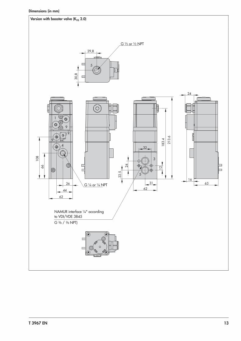
Dimensions (in mm)
Version with booster valve (KVS 2.0)
26
66
108
62
32
24
12
183
.4
213
.6
63
24
29,8
30,
8
22.
5
31
Int.
9
9.
9.
1
5
3
5
4
62
44
16
G ½ or ½ NPT
NAMUR interface ¼" according to VDI/VDE 3845G 3/8 / 3/8 NPT)
G ¼ or ¼ NPT
14 T 3967 EN
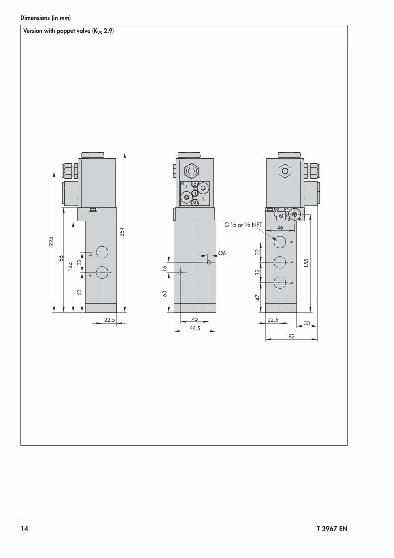
Dimensions (in mm)
Version with poppet valve (KVS 2.9)
45
66.5
63
16
Ø6
224
63
32
22.5
144
166
254
47
32
32
22.5
46
155
82
33
G ½ or ½ NPT
T 3967 EN 15
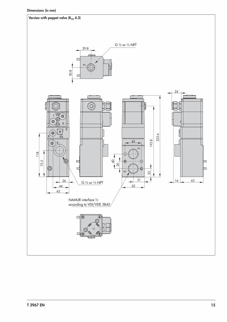
Dimensions (in mm)
Version with poppet valve (KVS 4.3)
5
Int.
9.
9.
9.
1
4
5
3
72.
5 1
18
62
45
40
20
193
.8 223.
6
63 31
23
26
30.
8
29.8
62
24
44
16
G ½ or ½ NPT
G ½ or ½ NPT
NAMUR interface ½ according to VDI/VDE 3845
16 T 3967 EN
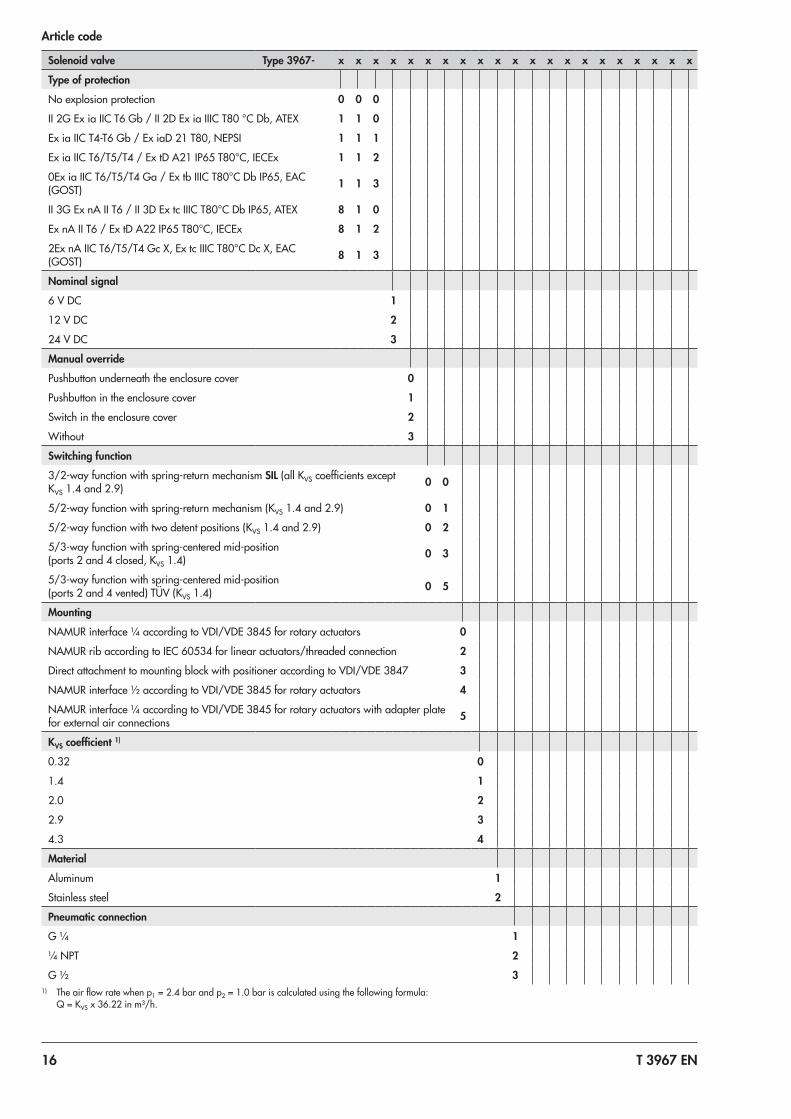
Article code
Solenoid valve Type 3967- x x x x x x x x x x x x x x x x x x x x x
Type of protection
No explosion protection 0 0 0
II 2G Ex ia IIC T6 Gb / II 2D Ex ia IIIC T80 °C Db, ATEX 1 1 0
Ex ia IIC T4-T6 Gb / Ex iaD 21 T80, NEPSI 1 1 1
Ex ia IIC T6/T5/T4 / Ex tD A21 IP65 T80°C, IECEx 1 1 2
0Ex ia IIC T6/T5/T4 Ga / Ex tb IIIC T80°C Db IP65, EAC (GOST) 1 1 3
II 3G Ex nA II T6 / II 3D Ex tc IIIC T80°C Db IP65, ATEX 8 1 0
Ex nA II T6 / Ex tD A22 IP65 T80°C, IECEx 8 1 2
2Ex nA IIC T6/T5/T4 Gc X, Ex tc IIIC T80°C Dc X, EAC (GOST) 8 1 3
Nominal signal
6 V DC 1
12 V DC 2
24 V DC 3
Manual override
Pushbutton underneath the enclosure cover 0
Pushbutton in the enclosure cover 1
Switch in the enclosure cover 2
Without 3
Switching function
3/2-way function with spring-return mechanism SIL (all KVS coefficients except KVS 1.4 and 2.9) 0 0
5/2-way function with spring-return mechanism (KVS 1.4 and 2.9) 0 1
5/2-way function with two detent positions (KVS 1.4 and 2.9) 0 2
5/3-way function with spring-centered mid-position (ports 2 and 4 closed, KVS 1.4) 0 3
5/3-way function with spring-centered mid-position (ports 2 and 4 vented) TÜV (KVS 1.4) 0 5
Mounting
NAMUR interface ¼ according to VDI/VDE 3845 for rotary actuators 0
NAMUR rib according to IEC 60534 for linear actuators/threaded connection 2
Direct attachment to mounting block with positioner according to VDI/VDE 3847 3
NAMUR interface ½ according to VDI/VDE 3845 for rotary actuators 4
NAMUR interface ¼ according to VDI/VDE 3845 for rotary actuators with adapter plate for external air connections 5
KVS coefficient 1)
0.32 0
1.4 1
2.0 2
2.9 3
4.3 4
Material
Aluminum 1
Stainless steel 2
Pneumatic connection
G ¼ 1
¼ NPT 2
G ½ 31) The air flow rate when p1 = 2.4 bar and p2 = 1.0 bar is calculated using the following formula:
Q = KVS x 36.22 in m³/h.
T 3967 EN 17
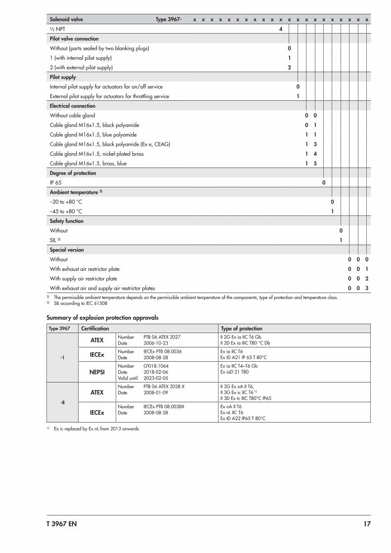
Solenoid valve Type 3967- x x x x x x x x x x x x x x x x x x x x x
½ NPT 4
Pilot valve connection
Without (ports sealed by two blanking plugs) 0
1 (with internal pilot supply) 1
2 (with external pilot supply) 2
Pilot supply
Internal pilot supply for actuators for on/off service 0
External pilot supply for actuators for throttling service 1
Electrical connection
Without cable gland 0 0
Cable gland M16x1.5, black polyamide 0 1
Cable gland M16x1.5, blue polyamide 1 1
Cable gland M16x1.5, black polyamide (Ex e, CEAG) 1 3
Cable gland M16x1.5, nickel-plated brass 1 4
Cable gland M16x1.5, brass, blue 1 5
Degree of protection
IP 65 0
Ambient temperature 2)
–20 to +80 °C 0
–45 to +80 °C 1
Safety function
Without 0
SIL ³) 1
Special version
Without 0 0 0
With exhaust air restrictor plate 0 0 1
With supply air restrictor plate 0 0 2
With exhaust air and supply air restrictor plates 0 0 3
Summary of explosion protection approvalsType 3967 Certification Type of protection
-1
ATEX Number PTB 06 ATEX 2027 II 2G Ex ia IIC T6 GbII 2D Ex ia IIIC T80 °C DbDate 2006-10-23
IECEx Number IECEx PTB 08.0036 Ex ia IIC T6Ex tD A21 IP 65 T 80°CDate 2008-08-28
NEPSINumber GYJ18.1064 Ex ia IIC T4~T6 Gb
Ex iaD 21 T80Date 2018-02-06Valid until 2023-02-05
-8
ATEXNumber PTB 06 ATEX 2028 X II 3G Ex nA II T6,
II 3G Ex ic IIC T6 1)
II 3D Ex tc IIIC T80°C IP65Date 2008-01-09
IECExNumber IECEx PTB 08.0038X Ex nA II T6
Ex nL IIC T6Ex tD A22 IP65 T 80°C
Date 2008-08-28
1) Ex ic replaced by Ex nL from 2013 onwards
2) The permissible ambient temperature depends on the permissible ambient temperature of the components, type of protection and temperature class.3) SIL according to IEC 61508
18 T 3967 EN
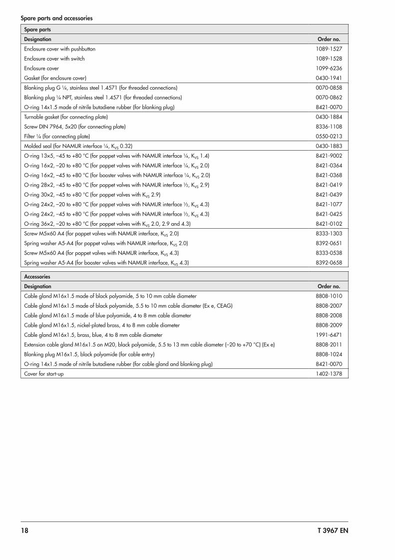
Spare parts and accessories
Spare parts
Designation Order no.
Enclosure cover with pushbutton 1089-1527
Enclosure cover with switch 1089-1528
Enclosure cover 1099-6236
Gasket (for enclosure cover) 0430-1941
Blanking plug G ¼, stainless steel 1.4571 (for threaded connections) 0070-0858
Blanking plug ¼ NPT, stainless steel 1.4571 (for threaded connections) 0070-0862
O-ring 14x1.5 made of nitrile butadiene rubber (for blanking plug) 8421-0070
Turnable gasket (for connecting plate) 0430-1884
Screw DIN 7964, 5x20 (for connecting plate) 8336-1108
Filter ¼ (for connecting plate) 0550-0213
Molded seal (for NAMUR interface ¼, KVS 0.32) 0430-1883
O-ring 13×5, –45 to +80 °C (for poppet valves with NAMUR interface ¼, KVS 1.4) 8421-9002
O-ring 16×2, –20 to +80 °C (for poppet valves with NAMUR interface ¼, KVS 2.0) 8421-0364
O-ring 16×2, –45 to +80 °C (for booster valves with NAMUR interface ¼, KVS 2.0) 8421-0368
O-ring 28×2, –45 to +80 °C (for poppet valves with NAMUR interface ½, KVS 2.9) 8421-0419
O-ring 30×2, –45 to +80 °C (for poppet valves with KVS 2.9) 8421-0439
O-ring 24×2, –20 to +80 °C (for poppet valves with NAMUR interface ½, KVS 4.3) 8421-1077
O-ring 24×2, –45 to +80 °C (for poppet valves with NAMUR interface ½, KVS 4.3) 8421-0425
O-ring 36×2, –20 to +80 °C (for poppet valves with KVS 2.0, 2.9 and 4.3) 8421-0102
Screw M5×60 A4 (for poppet valves with NAMUR interface, KVS 2.0) 8333-1303
Spring washer A5-A4 (for poppet valves with NAMUR interface, KVS 2.0) 8392-0651
Screw M5×60 A4 (for poppet valves with NAMUR interface, KVS 4.3) 8333-0538
Spring washer A5-A4 (for booster valves with NAMUR interface, KVS 4.3) 8392-0658
Accessories
Designation Order no.
Cable gland M16x1.5 made of black polyamide, 5 to 10 mm cable diameter 8808-1010
Cable gland M16x1.5 made of black polyamide, 5.5 to 10 mm cable diameter (Ex e, CEAG) 8808-2007
Cable gland M16x1.5 made of blue polyamide, 4 to 8 mm cable diameter 8808-2008
Cable gland M16x1.5, nickel-plated brass, 4 to 8 mm cable diameter 8808-2009
Cable gland M16x1.5, brass, blue, 4 to 8 mm cable diameter 1991-6471
Extension cable gland M16x1.5 on M20, black polyamide, 5.5 to 13 mm cable diameter (–20 to +70 °C) (Ex e) 8808-2011
Blanking plug M16x1.5, black polyamide (for cable entry) 8808-1024
O-ring 14x1.5 made of nitrile butadiene rubber (for cable gland and blanking plug) 8421-0070
Cover for start-up 1402-1378
T 3967 EN 19
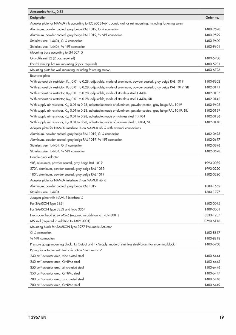
Accessories for KVS 0.32
Designation Order no.
Adapter plate for NAMUR rib according to IEC 60534-6-1, panel, wall or rail mounting, including fastening screw
Aluminum, powder coated, gray beige RAL 1019, G ¼ connection 1400-9598
Aluminum, powder coated, gray beige RAL 1019, ¼ NPT connection 1400-9599
Stainless steel 1.4404, G ¼ connection 1400-9600
Stainless steel 1.4404, ¼ NPT connection 1400-9601
Mounting base according to EN 60715
G-profile rail 32 (2 pcs. required) 1400-5930
For 35 mm top-hat rail mounting (2 pcs. required) 1400-5931
Mounting plate for wall mounting including fastening screws 1400-6726
Restrictor plate
With exhaust air restrictor, KVS 0.01 to 0.28, adjustable; made of aluminum, powder coated, gray beige RAL 1019 1400-9602
With exhaust air restrictor, KVS 0.01 to 0.28, adjustable; made of aluminum, powder coated, gray beige RAL 1019, SIL 1402-0141
With exhaust air restrictor, KVS 0.01 to 0.28, adjustable; made of stainless steel 1.4404 1402-0137
With exhaust air restrictor, KVS 0.01 to 0.28, adjustable; made of stainless steel 1.4404, SIL 1402-0142
With supply air restrictor, KVS 0.01 to 0.28, adjustable; made of aluminum, powder coated, gray beige RAL 1019 1400-9603
With supply air restrictor, KVS 0.01 to 0.28, adjustable; made of aluminum, powder coated, gray beige RAL 1019, SIL 1402-0139
With supply air restrictor, KVS 0.01 to 0.28, adjustable; made of stainless steel 1.4404 1402-0136
With supply air restrictor, KVS 0.01 to 0.28, adjustable; made of stainless steel 1.4404, SIL 1402-0140
Adapter plate for NAMUR interface ¼ on NAMUR rib ¼ with external connections
Aluminum, powder coated, gray beige RAL 1019, G ¼ connection 1402-0695
Aluminum, powder coated, gray beige RAL 1019, ¼ NPT connection 1402-0697
Stainless steel 1.4404, G ¼ connection 1402-0696
Stainless steel 1.4404, ¼ NPT connection 1402-0698
Double-axial adapter
90°, aluminum, powder coated, gray beige RAL 1019 1993-0089
270°, aluminum, powder coated, gray beige RAL 1019 1993-0220
180°, aluminum, powder coated, gray beige RAL 1019 1402-0280
Adapter plate for NAMUR interface ¼ on NAMUR rib ½
Aluminum, powder coated, gray beige RAL 1019 1380-1652
Stainless steel 1.4404 1380-1797
Adapter plate with NAMUR interface ¼
For SAMSON Type 3351 1402-0095
For SAMSON Type 3353 and Type 3354 1409-3001
Hex socket head screw M5x6 (required in addition to 1409-3001) 8333-1237
M5 seal (required in addition to 1409-3001) 0790-6118
Mounting block for SAMSON Type 3277 Pneumatic Actuator
G ¼ connection 1400-8817
¼ NPT connection 1400-8818
Pressure gauge mounting block, 1x Output and 1x Supply, made of stainless steel/brass (for mounting block) 1400-6950
Piping for actuator with fail-safe action "stem retracts"
240 cm² actuator area, zinc-plated steel 1400-6444
240 cm² actuator area, CrNiMo steel 1400-6445
350 cm² actuator area, zinc-plated steel 1400-6446
350 cm² actuator area, CrNiMo steel 1400-6447
700 cm² actuator area, zinc-plated steel 1400-6448
700 cm² actuator area, CrNiMo steel 1400-6449
Specifications subject to change without notice T 3967 EN 2019
-07-
15 ·
Engl
ish
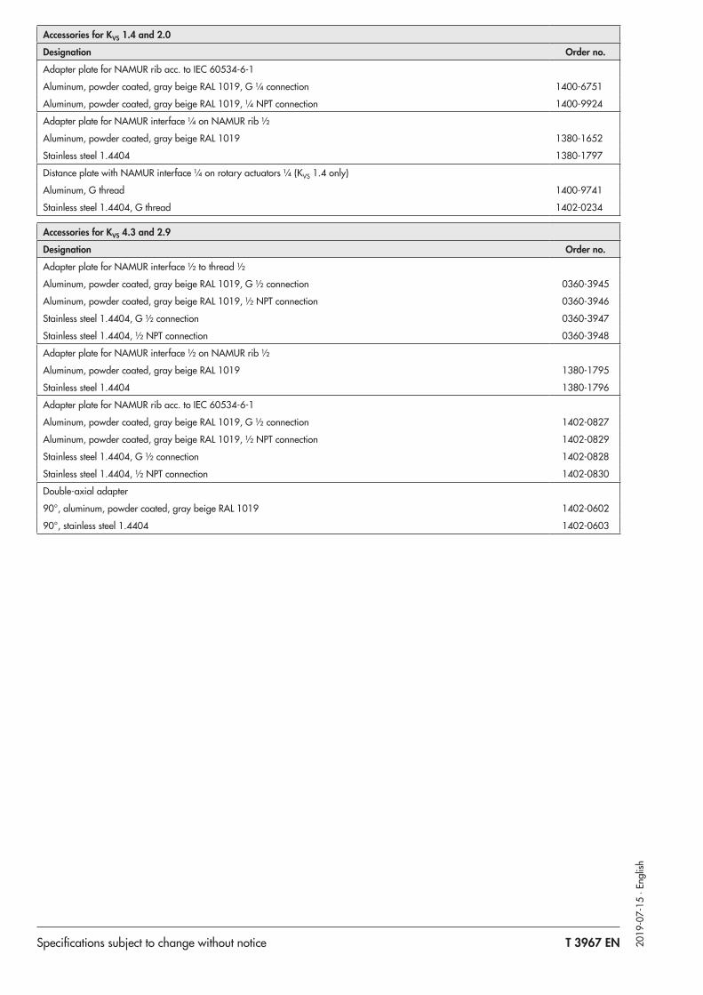
Accessories for KVS 1.4 and 2.0
Designation Order no.
Adapter plate for NAMUR rib acc. to IEC 60534-6-1
Aluminum, powder coated, gray beige RAL 1019, G ¼ connection 1400-6751
Aluminum, powder coated, gray beige RAL 1019, ¼ NPT connection 1400-9924
Adapter plate for NAMUR interface ¼ on NAMUR rib ½
Aluminum, powder coated, gray beige RAL 1019 1380-1652
Stainless steel 1.4404 1380-1797
Distance plate with NAMUR interface ¼ on rotary actuators ¼ (KVS 1.4 only)
Aluminum, G thread 1400-9741
Stainless steel 1.4404, G thread 1402-0234
Accessories for KVS 4.3 and 2.9
Designation Order no.
Adapter plate for NAMUR interface ½ to thread ½
Aluminum, powder coated, gray beige RAL 1019, G ½ connection 0360-3945
Aluminum, powder coated, gray beige RAL 1019, ½ NPT connection 0360-3946
Stainless steel 1.4404, G ½ connection 0360-3947
Stainless steel 1.4404, ½ NPT connection 0360-3948
Adapter plate for NAMUR interface ½ on NAMUR rib ½
Aluminum, powder coated, gray beige RAL 1019 1380-1795
Stainless steel 1.4404 1380-1796
Adapter plate for NAMUR rib acc. to IEC 60534-6-1
Aluminum, powder coated, gray beige RAL 1019, G ½ connection 1402-0827
Aluminum, powder coated, gray beige RAL 1019, ½ NPT connection 1402-0829
Stainless steel 1.4404, G ½ connection 1402-0828
Stainless steel 1.4404, ½ NPT connection 1402-0830
Double-axial adapter
90°, aluminum, powder coated, gray beige RAL 1019 1402-0602
90°, stainless steel 1.4404 1402-0603