Embed Size (px)
Citation preview

*rc
:
379 c OPY .e* * * . * * * R M E58A09
i g’& i 1: 2
4 GPO PRICE $
OTS PRICE(S) $
Hard copy (HC) 1 c”G T.
Microfiche (M F) 3u
. ..-
R E S EARCH
HIGH :
- K Y a 5 3 I il U a 0 U I- (L 0
0 a
3 5
MEMORAN DUM
ACH NUMBER, LOW -COWL-DRAG, EXTERNAL-COMPRESSION
I N L E T WITH SUBSONIC DUMP DIFFUSER
B y James F. C o n n o r s and R i c h a r d J. F l a h e r t y
L e w i s F l igh t Propuls ion L a b o r a t o r y Cleveland, Ohio
JATIONAL ADVISORY COMMITTEE FQR AERONAUTICS
WASHINGTON May 12, 1958
https://ntrs.nasa.gov/search.jsp?R=19650003110 2018-09-16T08:11:38+00:00Z

m a m m m a am m a m m m : * a m e m .
NACA RM E58A09
m m m ma. m m m m m a
a m m a a m m a
ma. m a
NATIONAL ADVISORY COMMITTEE FOR AERONAUTICS
RESWCH MEMORANDUM
HIGH MACH NUMBER, LOW-CGWL-DMG, IUTEN”L-COKF’8ESSLON
WITH SUBSONIC DUMP DIFFUSER
By James F. Connors and Richard J. Flaherty
SUMMARY
INLET
A zero-cowl-drag, all-external-compression inlet with an abrupt area discontinuity or subsonic dump diffuser has been proposed and demon- strated for high Mach number application. ‘Isentropic compression was focussed at the lip of a cylindrical cowl and limited by the requirements for shock attachment. Theoretical calculations of the performance of such an inlet showed that it may be suited for application at Mach num- bers of 4 and above.
In an experimental investigation at Mach 3.85, a 4.75-inch-diameter inlet attained a total-pressure recovery of O.+aZ a corresponding mass- flow ratio of 0.92. Subsonic diffusion over an area ratio of about 3.5 to 1.0 was accomplished in 1.25 inlet diameters. Essentially no differ- ence in performance was obtained in a comparison of the dump and a con- ventional subsonic diffuser. On a range basis, the over-all performance of this inlet was at least comparable with that of the best on-design isentropic external-compression inlet previously reported.
A variable Mach number configuration utilizing a telescop with a subsonic dump diffuser is also included.
INTRODUCTION
In the over-all evaluation of a particular inlet, internal perfor- IiiaiiL‘e l i iust be assessed in the light of its respective costs in drag, weight, and mechanical complexity. This is especially true for inlets at speeds above Mach 3, where the need for maintaining low external drag and for using variable geometry to accommodate variable-Mach-number oper- ation is generally accepted.
All-external-compression inlets in achieving high internal perform- ance (ref. 1) are generally penalized by cowl drags which represent a significant portion of the net engine thrust (e.g., in ref. 2, cowl drags

2
alone accounted for 10 to 20 percent of engine thrust, at Mach 3). all-internal-compression inlet (ref. 3), on the other hand, achieves high pressure recoveries with virtually no cowl drag, but requires rather long gradual compression surfaces which, in the axisyrmnetric case, may require spike-translation distances of 2 to 3 inlet diameters. Also, in contrast to the external-compression type, the internal-compression inlet appears to be limited to supercritical or critical operation because of the severe discontinuity in performance with expelled-shock operation. A combination external-plus-internal-compression inlet (ref. 4) has recently shown a very high over-all performance at Mach 3.0. This inlet, in addition, re- quires only a relatively small amount of spike translation and has a rather short over-all length.
The
In the present study, the external-compression inlet was examined fur- ther f r o m the viewpoint of achieving a short zero-cowl-drag configuration for operation at a Mach number of 3.85. First considerations were based solely on a fixed Mach number design. A cylindrical cowl was used with isentropic all-external compression focussed at the lip and limited by the requirements for shock attachment on the cowl. The over-all confi- guration employed an abrupt area discontinuity, or dump, instead of the conventional subsonic diffuser. This design approach possesses the po- tential advantages of a short over-all length and correspondingly low weight.
*
In order to evaluate such an approach to high Mach number inlet de- sign, an experimental investigation was conducted on a small-scale model at a Mach number of 3.e5. covery and mass-flow ratio) was determined for a limited range of spike tip projections and angles of attack. Surveys of the internal flow were made at several axial stations to determine effective subsonic diffuser lengths.
Internal performance (i.e., total-pressure re- *
Based on the results of this present study, the theoretical perfor- mance of this type of inlet was analyzed for a wide range of Mach numbers to put it in the proper perspective with relation to other supersonic in- let types. geometry-inlet proposal, utilizing the principle of the subsonic dump diffuser at high Mach numbers in combination with a telescoping spike is also included.
To accommodate variable Mach number operation, a variable-
SYMBOLS
The following symbols are used in this report:
inlet capture area, sq ft Ain
diffuser-exit flow areaJ sq ft A3

.
UJ M W dc
M
9 s r: e r,
.
...... . . . . . ..... . . . . ....... NACA RM E58A09
M
m3/mg
P
'3/'0
P
9
v
-
X
U
$ 2
P
. ............... w' . . . . . . . . . . . . . ..... . . . . . . ........ 3
Mach number
inlet mass-flow ratio, p3A3V3/p&inVo
total pressure, lb/sq ft
total-pressure recovery
static pressure, 1b/sq ft
dynamic pressure, lb/sq ft
air velocity , ft/sec distance, in.
angle of attack, deg
cowl-position parameter, angle between axis of symmetry and line from spike tip to cowl lip, deg
density of air, lb/cu ft
Subscripts:
Z lip
0 conditions in free stream
3 conditions at diffuser exit
Superscript:
area-weighted value -
DESIGN CONSIDERATIONS
The L n l e t configuration studied herein utilized a cylindrical cowl with all-external isentropic compression that was focussed at t.he lip and limited by the requirements for shock attachment on the cowl. At Mach 4.0, the theoretical Mach numbers behind the terminal shock are only about 0.5. The corresponding dynamic head is relatively small. In fact, by assuming a complete l o s s of this dynamic head, which might hap- pen in the mixing processes involved in dumping the flow, little effect on kinetic-energy efficiency would result. pressure recovery of 0.54, or a kinetic-energy efficiency of 0.95, might be possible with no turning loss and an ideal subsonic diffuser; whereas
For example, at Mach 4.0 a
r ............... ....... . . . . . . . . . . . . . . . . . . . . . . . . . . . . . . . . . . 4
. 0 . . - - - *.: 0.: : : : .......
NACA RM ~ 5 8 ~ 0 9
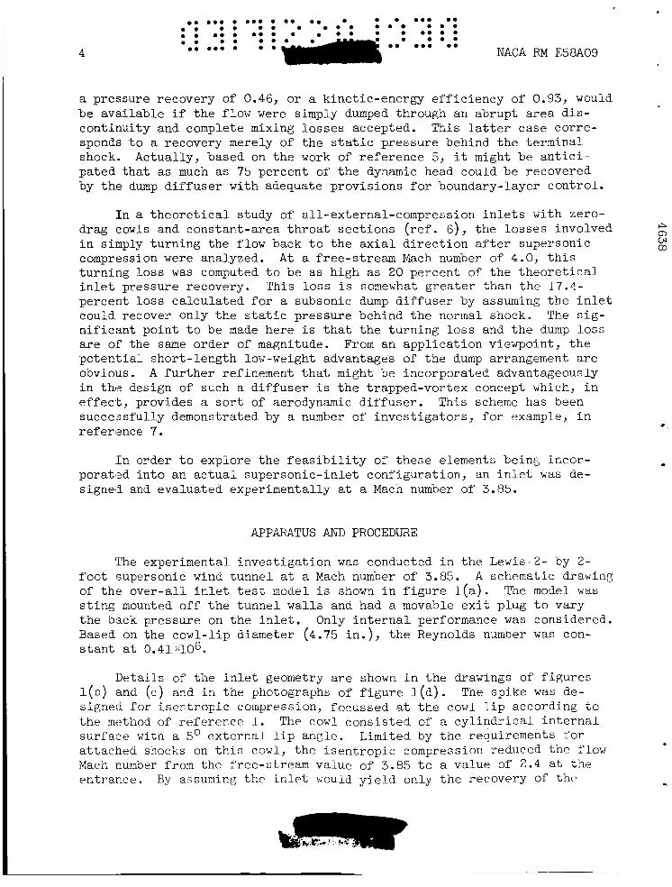
a pressure recovery of 0.46, or a kinetic-energy efficiency of 0.93, would be available if the flow were simply dumped through an abrupt area dis- continuity and complete mixing losses accepted. This latter case corre- sponds to a recovery merely of the static pressure behind the terminal shock. Actually, based on the work of reference 5, it might be antici- pated that as much as 75 percent of the dynamic head could be recovered by the dump diffuser with adequate provisions for boundary-layer control.
In a theoretical study of all-external-compression inlets with zero- I+ cn Lrl 0)
drag cowls and constant-area throat sections in simply turning the flow back to the axial direction after supersonic
(ref. 6), the losses involved
compression were analyzed. At a free-stream Mach number of 4.0, this turning loss was computed to be as high as 20 percent of the theoretical inlet pressure recovery. This loss is somewhat greater than the 17.4- percent l o s s calculated for a subsonic dump diffuser by assuming the inlet could recover only the static pressure behind the normal shock. The sig- nificant point to be made here is that the turning l o s s and the dump loss are of the same order of magnitude. From an application viewpoint, the potential short-length low-weight advantages of the dump arrangement are obvious. A further refinement that might be incorporated advantageously in the design of such a diffuser is the trapped-vortex concept which, in effect, provides a sort of aerodynamic diffuser. This scheme has been succeasfully demonstrated by a number of investigators, for example, in reference 7. *
In order to explore the feasibility of these elements being incor- L
poratzd into an actual supersonic-inlet configuration, an inlet; was de- signed and evaluated experimentally at a Mach number of 3.85.
APPARATUS AND PROCEDURE
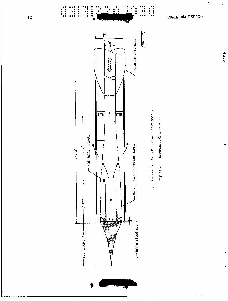
The experimental investigation was conducted in the Lewis 2- by 2- foot supersonic wind tunnel at a Mach number of 3.85. A schematic drawing of the over-all inlet test model is shown in figure l(a>. sting mounted off the tunnel walls and had a movable exit plug to vary the back pressure on the inlet. Only internal performance was considered. Based on the cowl-lip diameter (4.75 in.), the Reynolds number was con- stant at 0.41;:106.
The model was
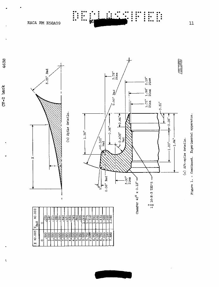
Details of the inlet geometry are shown in the drawings of figures l ( ~ ) and (c) and in the photographs of figure l(d). signed for isentropic compression, focussed at the cowl lip according to the method of reference 1. The cowl consisted of a cylindrical internal surface with a 5' external lip angle. attached snocks on this cowl, the isentropic compression reduced the flow Mach number from the f'ree-stream value of 3.85 to a value of 2.4 at the entrance.
The spike was de-
Limited by the requirements f o r
i3y assuming the inlet would yield only the recovery Of the
. NACA RM E58A09 5
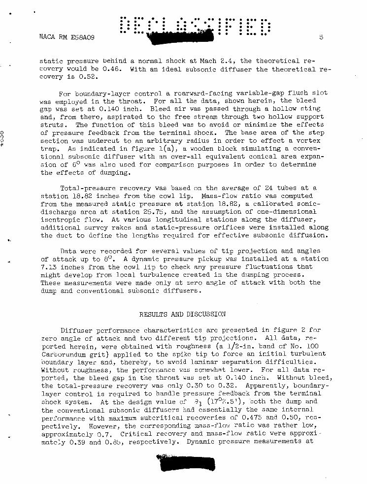
s t a t i c pressure behind a normal shock at Mach 2.4, t h e t h e o r e t i c a l re- covery would be 0.46. With an i d e a l subsonic d i f f u s e r t h e t h e o r e t i c a l r e - covery i s 0.52.
For boundary-layer c o n t r o l a rearward-facing var iable-gap f l u s h s l o t w a s employed l a t h e t h r o a t . For a l l the data, shown he re in , t h e b leed gap w a s set a t 0.140 inch. Bleed a i r was passed through a hollow s t i n g and, from the re , a sp i r a t ed t o the f r e e stream through t w o hollow support s t r u t s . The func t ion of t h i s bleed was t o avoid o r minimize t h e e f f e c t s of pressure feedback from t h e terminal shock. The base a r e a of t h e s t e p s e c t i o n was undercut t o an a r b i t r a r y radius i n order t o e f f e c t a vor tex t r ap . A s i nd ica t ed i n f i g u r e l (a ) , a wooden block s imula t ing a conven- t i o n a l subsonic d i f f u s e r with an over -a l l equivalent con ica l area expan- s ion of 6' w a s a l s o used f o r comparison purposes i n order t o determine t h e e f f e c t s of dumping.
Total-pressure recovery w a s based on t h e average of 24 tubes a t a s t a t i o n 18.82 inches from t h e cowl l i p . Mass-flow r a t i o w a s computed from t h e measured s t a t i c pressure a t s t a t i o n 18.82, a c a l i b r a t e d sonic- discharge area a t s t a t i o n 25.75, and the assumption of one-dimensional i s e n t r o p i c flow. A t var ious longi tudina l s t a t i o n s along t h e d i f f u s e r , a d d i t i o n a l survey rakes and s t a t i c -p res su re o r i f i c e s were i n s t a l l e d along t h e duct t o def ine t h e lengths required f o r e f f e c t i v e subsonic d i f fus ion .
Data were recorded f o r s e v e r a l values of t i p p ro jec t ion and angles of a t t a c k up t o 8O. 7.13 inches from t h e cowl l i p t o check any pressure f l u c t u a t i o n s t h a t might develop from l o c a l turbulence created i n t h e dumping process . These measurements were made only at zero angle of a t t a c k with both the dump and conventional su-bsonic d i f fuse r s .
A dynamic pressure pickup w a s i n s t a l l e d a t a s t a t i o n
RESULTS AND DISCUSSION
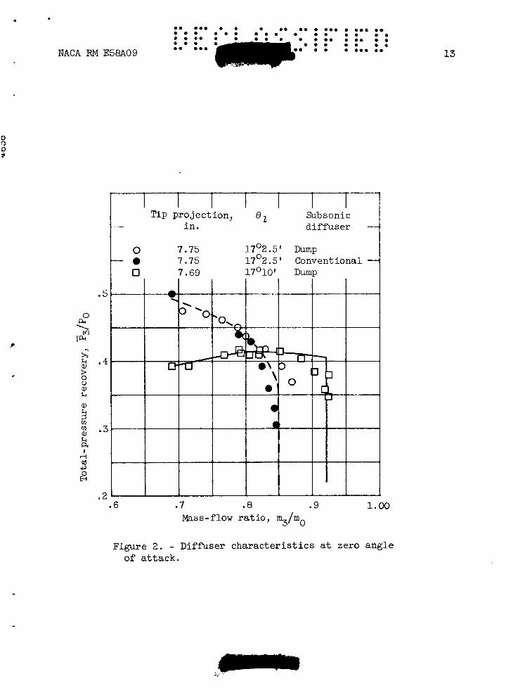
Dif fuser performance c h a r a c t e r i s t i c s a r e presented i n f i g u r e 2 f o r zero angle of a t t a c k and two difPerent t i p p ro jec t ions . A l l da t a , r e - por ted here in , were obtained with roughness (a 1/2-in. band of N o . 100 Carborundum g r i t ) appl ied t o the spike t i p t o fo rce an i c i t i a l tu rbu len t boundary layer and, thereby, t o avoid laminar separa t ion d i f f i c u l t i e s . Without roughness, t he perfortiaiice \:as soxewhat lower. For a l l d a t a r e - ported, the bleed gap i n t h e t h r o a t was s e t a t 0.140 inch. Without bleed, t h e to t a l -p re s su re recovery w a s only 0.30 t o 0.32. Apparently, boundary- l aye r c o n t r o l i s requi red t o handle pressure feedback from t h e te rmina l shock system. t h e conventional subsonic d i f f u s e r s had e s s e n t i a l l y t h e same i n t e r n a l performance with maximum s u b c r i t i c a l recover ies of 0.475 and 0.50, r e s - pec t ive ly . However, the corresponding mass-flow r a t i o w a s r a t h e r low, approximately 0.7. C r i t i c a l recovery and mass-flow r a t i o vere approxi - mately 0.39 and 0.35, respec t ive ly . Dynamic pressure measurements a t
A t t h e design value of 41 (17'%.5'), both the dump and

6
Sta t i c -p res su re d i s t r i b u t i o n s along t h e subsonic duct a t zero angle of a t t ack and a 82 of 17O2.5' a r e presented i n f i g u r e 4 for s e v e r a l values of t o t a l - p r e s s u r e recovery. For t h e most p a r t , t he s t a t i c - p r e s s u r e r i s e i n the dump d i f f u s e r had been accomplished i n approximately 1.25 i n l e t diameters (5.94 i n . from t h e cowl l i p ) . A s i nd ica t ed by t h e s e da ta , t h e normal-shock pressure r ise i s spread out over a considerable d is tance , and the re appears t o be no sharp rise, such as t h e o r e t i c a l l y considered through a s i n g l e f i n i t e te rmina l shock. I n theory, a pressure r i s e (p/Po) t o 0.46 was an t i c ipa t ed . s t a t i o n s a re shown i n f i g u r e 5 f o r t h r e e d i f f e r e n t recovery l eve l s , cor- responding t o s u p e r c r i t i c a l , approximately c r i t i c a l , and s u b c r i t i c a l oper- a t i n g conditions. The da ta a t s t a t i o n 7.13 inches (1.5 i n l e t dim) down- stream of t h e cowl l i p ind ica t ed no sepa ra t ion a t any po in t across t h e e n t i r e duct annulus f o r a l l t h r e e condi t ions. A t c r i t i c a l , t h e d i s t o r t i o n
Tota l -pressure p r o f i l e s a t var ious a x i a l
~
l e v e l i s extremely low at t h i s s t a t i o n . A s t h e i n l e t became s u b c r i t i c a l ,
............... . . 0.. 0 . . . . . . . . . . . . . . . . . . . . . . . . . . . . . . . . . . . 0 . 0 . 0 . ........ NACA RM ~ 5 8 ~ 0 9
s t a t i o n 7.13 inches from t h e cowl l i p ind ica t ed no d i f f e rence i n t h e lev- e l of flow f l u c t u a t i o n with the dump as compared w i t h t h a t using t h e con- vent iona l d i f f u s e r .
By r e t r a c t i n g t h e sp ike 1/16 of an inch t o a 82 s u p e r c r i t i c a l mass-flow r a t i o w a s increased t o 0.92 with a c r i t i c a l re- covery of approximately 0.41. S tab le s u b c r i t i c a l operatior, of t h e i n l e t w a s r ea l i zed down t o a mass-flow r a t i o or' about 0.7 with l i t t l e change i n recovery l e v e l .
of 17'10', t he
To p lace t h i s i n l e t i n i t s proper perspec t ive with r e l a t i o n t o o ther configurat ions, it can be pointed out t h a t i t s i n t e r n a l performance (re- covery, 0.41; mass-flow r a t i o , 0.92) w a s about t h e same as t h a t a t t a i n e d with the convent ional on-design two-cone i n l e t repor ted i n re ference 8. Similar ly , an on-design i s e n t r o p i c i n l e t a t a Mach number of 3.85 gave. a 0.57 recovery, bu t with an a t tendant cowl-pressure drag. Approximate ca l cu la t ions were made t o compare t h e ove r -a l l performance of t hese in - l e t s on a maximum-range bas i s . It w a s assumed t h a t t h e add i t ive drags were the same f o r bo th i n l e t s s ince t h e i r capture mass flows were equal. The experimental coQ1-pressure drag w a s given i n re ference 8 f o r the high-recovery i n l e t . The conf igura t ion of t h i s s tudy with i t s e s s e n t i a l l y zero-cowl-pressure drag and subsonic dump arrangement w a s a t least compar- ab le with t h e on-design i s e n t r o p i c i n l e t of re ference 8.
*\
A sch l i e re8 photograph of t h e s u p e r c r i t i c a l i n l e t a i r f low p a t t e r n f o r a A t zero angle of a t t a c k t h e compression waves appear t o focus somewhat ahead of t h e cowl l i p , t hus ind ica t ing some flow sp i l l age . A t t h e sp ike t i p , t he g r i t or roughness appl ied here as an a r t i f i c i a l . boundary-layer t r i p may be seen. The boun- dary layer along t h e contoured sp ike appears we l l behaved with no ind ica- t i o n s of separa t ion . 8 2 , t h e s p i l l a g e around t h e cow' l i p w a s diminished, bu t l i t t l e change i n flow p a t t e r n w a s noted.
82 of 17 2.5' i s shown i n f i g u r e 3.
A t t h e 17O10' va lue of

. am a a a a m . a a ma a m . am ma. NACA RM E58A09
the re w a s a r e v e r s a l i n t r end i n t h a t the high-energy a i r , i nd ica t ed by t h e peak i n t h e p r o f i l e s , s h i f t e d from near t h e outer s h e l l towards t h e s t i ng . However, t h e p r o f i l e a t s t a t i o n 7.13 w a s s t i l l q u i t e f l a t .
The e f f e c t s of angle of a t t a c k on i n t e r n a l performance a r e ind ica t ed i n f i g u r e 6. A s i s genera l ly t y p i c a l of axisymmetric i n l e t s , t o t a l - pressure recovery and mass-flow r a t i o decreased moderately with angles up t o 8', and t h e recovery w a s approximately 0.30.
1 I > Calculat ions were made t o es t imate t h e pressure-recovery p o t e n t i a l
of i s en t rop ic zero-cowl-drag i n l e t s w i t h subsonic dump d i f f u s e r s over a wide range of supersonic Mach numbers. The r e s u l t s a r e presented i n f i g u r e 7. The cross-hatched band indica tes t h e t h e o r e t i c a l recovery f o r i s en t rop ic a l l - e x t e r n a l compression car r ied t o the l i m i t of shock a t t ach - ment on a c y l i n d r i c a l cowl. The upper boundary shows t h e l e v e l of per- formance poss ib le with an i d e a l (no lo s s ) subsonic d i f f u s e r , while t h e lower boundary represents t h a t f o r f u l l dumping loss or a recovery of only t h e s t a t i c pressure behind t h e terminal shock. A s shown i n f i g u r e ' 7 , t h e r e s u l t s of t h e present exploratory study f a l l c lose t o and somewhat be- low t h e lower boundazy. For comparison purposes, l i n e s corresponding t o normal-shock recovery and t h e t h e o r e t i c a l all-external-compression l i m i t of re ference 1 a r e a l s o included. The i s en t rop ic zero-drag-cowl i n l e t wi th subsonic dump appears q u i t e competitive a t t h e higher Mach numbers (4.0 and above). This, of course, i s because of t h e low subsonic Mach numbers i n t h e t h r o a t . As free-stream Mach number decreases , t h i s sub- sonic t h r o a t Mach nwdlser increases , and t h e f e a s i b i l i t y of dumping and accept ing a high mixing loss diminishes r a t h e r rap id ly . For example, a t Mach 2.0 a complete loss of t h e subsonic dynamic pressure q would re- s u l t i n less than normal-shock recovery.
4
,*6
4
An extension of t h e dump p r in i cp le t o a variable-geometry i n l e t cap- ab le of operat ing over a wide range of Mach numbers i s i l l u s t r a t e d i n f i g u r e 8. To approximate t h e t h e o r e t i c a l v a r i a t i o n i n i s e n t r o p i c sur face contour with free-s t ream Mach number, a te lescoping sp ike ( r e f . 9) w a s assumed. A t t h e higher Mach number conditions, a dumping arrangement as shown i n f i g u r e 8(b) w a s used. or t h r o a t elements of t he te lescoping centerbody a r e successively re- t r a c t e d i n t o t h e subsonic d i f f u s e r , thus increas ing t h e t h r o a t area. I n t h e r e t r a c t e d pos i t i ons , t h e flow goes through, as w e l l as around, t h e r ings . A t t h e same t i m e , the elemer,ts n f t h e spike t r a n s l a t e r e l a t i v e t o each o ther t o form an envelope contour f o r i s en t rop ic focussed compres- s ion corresponding t o each Mach number. The cowl or t h e e n t i r e center- body a l s o t r a n s l a t e s t o keep t h e l i p a t t h e f o c a l po in t . For a l l s e t t i n g s of t h e spike, boundary-layer con t ro l can be maintained a t t h e i n l e t t h r o a t , as w a s done i n t h e present study. f i g u r a t i o n , t h e geometry of a somewhat conventional subsonic d i f f u s e r i s approached.
A s the Mach number decreases , t h e shoulder
For t h e low Mach number con- -.
*

0 . e.. . 0 . 0 . 0 . 0 . . . . e.. 0 . * * 0 . 0 . . 0 . . 0 . . e . .
8
0 . . . 0 . .
0.. 0 .
- . . . .. . 0 . . 0 .
NACA RM E58A09 0 . 0.. . . . The obvious disadvantage to such a scheme might be complexity. How-
ever, it should be possible in an actual full-scale version to design some type of cam or variable-pitch-screw arrangement to program these telescoping elements with the Mach number. The dumping provisions at high speeds, of course, tend towards weight savings. Against such me- chanical problems must be weighed the potential aerodynamic performance of such an inlet.
CONCLUDING R W K S
A zero-cowl-drag, all-external-compression inlet with a subsonic dump diffuser has been investigated at Mach 3.85. isentropic spike with compression focussed at the lip of a cylindrical cowl and limited by the requirements for shock attachment. An abrupt area discontinuity, or dump, was used instead of the conventional subsonic diffuser. of 0.92 were obtained with this dump diffuser. Subsonic diffusion over an area ratio of about 3.5 to 1.0 was accomplished in 1.25 inlet diame- ters. Essentially no difference in performance was obtained in a com- parison of dump and conventional subsonic diffusers.
This inlet had an
At Mach 3.85 a pressure recovery of 0.41 and a mass-flow ratio
rl C t 0
The results of this study substantiate the feasibility of utilizing the dump principle for high Mach number inlet application. The dump .r principle may be best suited for use at Mach numbers of 4 and higher. Further study with larger scale models appears desirable to evaluate any viscous effects upon performance. With this type of inlet it might be expected that the small scale models of the present study would 7;e more sensitive to the adverse effects of shock-boundary-layer interaction and the strong mixing processes inherent in such a flow system.
Lek; s Flight Propulsion Laboratory National Advisory Committee for Aeronautics
Cleveland, Ohio, January 13, 1958
REFERENCES
1. Connors, James F., and Meyer, Rudolph C.: Design Criteria for Axi- symmetric and Two-Dimensional Supersonic Inlets and Exits. NACA TN 3589, 1956.
2. Connors, James F., Wise, George A., and Lovell, J. Calvin: Investiga- tion of Translating-Double-Cone Axisymmetric Inlets with Cowl Pro- jected Areas 40 and 20 Percent of Maximum at Mach Numbers from 3.0 to 2.0. NACA RM E57C06, 1957.
Q) M a d
N
u &
3. Mossman, Emmet A., and Pfyl, Frank A.: A Study of a Symmetrical, Circular, Internal Compression Inlet. NACA RM A55L16, 1956.
4. Obery, Leonard J., and Stitt, Leonard E.: Performance of External- Internal Compression Inlet with Abrupt Internal Turning at Mach Numbers 3.0 to 2.9. NACA RM E57H07a, 1957.
9
5. Henry, John R., and Wilbur, Stafford W.: Preliminary Investigation of the Flow in an Annular-Diffuser - Tailpipe Combination with an Abrupt Area Expansion and Suction, Injection, and Vortex-Generator Flow Controls. NACA RM L53K30, 1954.
6. Meyer, Rudolph C.: Flow-Turning Losses Associated with Zero-Drag External Compression Supersonic Inlets. NACA TN 4096, 1957.
7. Woollett, Richard R.: Preliminary Investigation of Short Two- Dimensional Subsonic Diffusers. NACA RM E56C02, 1956.
8. Connors, James F., and Woollett, Richard R.: Force, Moment, and Pres- sure Characteristics of Several Annular Nose Inlets at Mach 3.85. NACA RM E53J09, 1954.
9. Connors, James F., and Meyer, Rudolph C.: A Variable-Geometry Axi- symmetric Supersonic Inlet with Tzlescoping Centerbody. NACA RM E55F30, 1955.
10
l-
li 8 d c) 0 'c3 0 a a d i3 I
rl F U a
c, d n a,
L
I
NACA RM E58A09
IP m w 03
NACA RM E58A09
i-
11
0 x M
I
10 ?
I
d
m
rl Fr
.

.e 0.. 0 0 0 0 0 0 . O C 0 0 0 0.0 0 . . m a * e . 0 0 . . 0 . 0 0 . 0
12
$ P a a, rl rl
2 b f!
rl
0
d F h a 0 P
c, Fl e, u
8
NACA RM E58A09
Y
k?
c, 5 k 5 a
w k cl
a a, a 3 2 V I
NACA RM E58A09
r q - - - i -I Tip pro jec t ion , e 2 Subsonic i n . d i f f u s e r
0 7.75 17'2.5 I Dump 0 7.75 17O2.5 I Conventional 0 7.69 170101 Dump 1
.5
.4
.3
.2 .6 .7 .a .9 1.00
Mass-flow r a t i o , 3 / m o
Figure 2 . - Diffuser c h a r a c t e r i s t i c s a t zero angle of a t t a c k .
13

Figure 3. - I n l e t a i r f l o w p a t t e r n a t zero angle of attack.

am mme a am ma a m m a ma* m a a m m m a . * a m m a a m a m a m m a r am m e m a a a m m a a m NACA RM E58A09 ma am* a m a a a m a
0 lo d! ?

16
k a I
r i a!
2
NACA RM E58A09
.45
.40
.35
.45
.40 0 .25 .50 .75 1.00 1.25 1.50
Annular dis tance, x, i n .
Figure 5 . - Total-pressure p r o f i l e s a t var ious a x i a l s t a t i o n s . Zero angle of a t t ack ; cowl-position parameter, 1702.5 I .

NACA RM E58A09
0 2 4 6 Angle of a t t ack , a, deg
8
Figure 6. - Effect of angle of a t t a c k on i n t e r n a l performance. Cowl-positim paraneter, 17O2.5'.

18

. m e m e
m e e ma c a m m a
C O ~ mo
- m a m a m a
ma am0 ma NACA RM E58A09 19
6
d a a a 9
5 d F 9
d F
. V
CI 6 v
h
P v
T
NACA - Langley Field, Va.
A

4
0 d:
rl rl
4 2 0
.
N
0 9
0 * d t-
0
r - d * o * c 'Qd
m
M
b 0
c, + Q I 0 0 0
ul
0 4
0
rl
0 4
Lo
m m Lo
m 1 4 It
W
9 a
J
c 0 4 * ri
ji 7
8" .
I - - d v
N v


![Dum-Dum WS1 [Pieles Responsivas]](https://img.pdfslide.net/doc/110x75/568c48ea1a28ab4916921552/dum-dum-ws1-pieles-responsivas.jpg)