Embed Size (px)
Citation preview
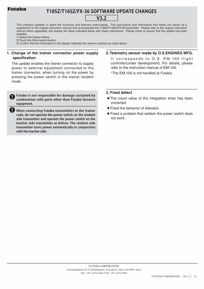
Futaba is not responsible for damage sustained by combination with parts other than Futaba Genuine equipment.
When connecting Futaba transmitters to the trainer code, do not operate the power switch on the student side transmitter and operate the power switch on the teacher side transmitter as before. The student side transmitter turns power automatically in conjunction with the teacher side.
T18SZ/T16SZ/FX-36 SOFTWARE UPDATE CHANGESV3.2
This software updates or alters the functions and features noted below. The instructions and information that follow are meant as a supplement to the original instruction manual that accompanied the T18SZ/T16SZ/FX-36 transmitter. Please refer to the original instruction manual where applicable, but replace the steps indicated below with these instructions. Please check to ensure that the update has been installed.1) Select the System Menu.2) Touch the [Information] button.3) Confirm that the information in the display indicates the version numbers as noted above.
FUTABA CORPORATION oak kandakajicho 8F 3-4 Kandakajicho, Chiyoda-ku, Tokyo 101-0045, Japan
TEL: +81-3-4316-4820, FAX: +81-3-4316-4823 ©FUTABA CORPORATION 2017, 12 (1)
1. Change of the trainer connector power supply specification
The update enables the trainer connector to supply power to external equipment connected to the trainer connector, when turning on the power by pressing the power switch in the trainer student mode.
2. Telemetry sensor made by O.S.ENGINES MFG.
I t c o r r e s p o n d s t o O . S . E M - 1 0 0 f l i g h t controller(under development). For details, please refer to the instruction manual of EM-100.
*The EM-100 is not handled at Futaba.
3. Fixed defect◆ The count value of the integration timer has been
corrected.◆ Fixed the behavior of Ailevator.◆ Fixed a problem that seldom the power switch does
not work.
- 1 -
1M23Z04317T18SZ SOFTWARE UPDATE CHANGES
V3.1This software updates or alters the functions and features noted below. The instructions and information that follow are meant as a supplement to the original instruction manual that accompanied the T18SZ transmitter. Please refer to the original instruction manual where applicable, but replace the steps indicated below with these instructions. Please check to ensure that the update has been installed.1) Select the System Menu.2) Touch the [Information] button.3) Confirm that the information in the display indicates the version numbers as noted above.
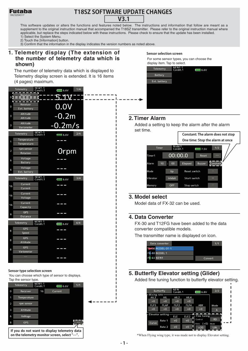
1. Telemetry display (The extension ofthe number of telemetry data which isshown)The number of telemetry data which is displayed toTelemetry display screen is extended. It is 16 items(4 pages) maximum.
2. Timer AlarmAdded a setting to keep the alarm after the alarmset time.
3. Model selectModel data of FX-32 can be used.
4. Data ConverterFX-30 and T12FG have been added to the dataconverter compatible models.
The transmitter name is displayed on icon.
Sensor type selection screen
Sensor selection screen
You can choose which type of sensor to displays. Tap the sensor type.
For some sensor types, you can choose the display item. Tap to select.
5. Butterfly Elevator setting (Glider)Added fine tuning function to butterfly elevator setting.
*When Flying wing type, it was made not to display Elevator setting.
Constant: The alarm does not stopOne time: Stop the alarm at once
If you do not want to display telemetry data on the telemetry monitor screen, select "---".
- 2 -
FUTABA CORPORATIONMakuhari Techno-Garden Bldg. B-6F, 1-3 Nakase, Mihama-ku, Chiba, 261-8555, Japan
Phone: +81-43-296-8259, Facsimile: +81-43-296-8253
©FUTABA CORPORATION 2017, 10 (1)
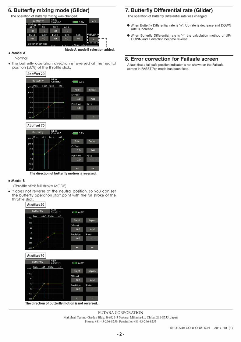
7. Butterfly Differential rate (Glider)The operation of Butterfly Differential rate was changed.
6. Butterfly mixing mode (Glider)The operation of Butterfly mixing was changed.
Mode A, mode B selection added.
◆When Butterfly Differential rate is "-", the calculation method of UP/DOWN and a direction become reverse.
◆When Butterfly Differential rate is "+", Up rate is decrease and DOWNrate is increase.
At offset 20
At offset 20
At offset 70
At offset 70
The direction of butterfly motion is reversed.
The direction of butterfly motion is not reversed.
● Mode A(Normal)
● The butterfly operation direction is reversed at the neutralposition (50%) of the throttle stick.
● Mode B(Throttle stick full stroke MODE)
● It does not reverse at the neutral position, so you can setthe butterfly operation start point with the full stroke of thethrottle stick.
8. Error correction for Failsafe screenA fault that a fail-safe position indicator is not shown on the Failsafe screen in FASST-7ch mode has been fixed.
- 3-
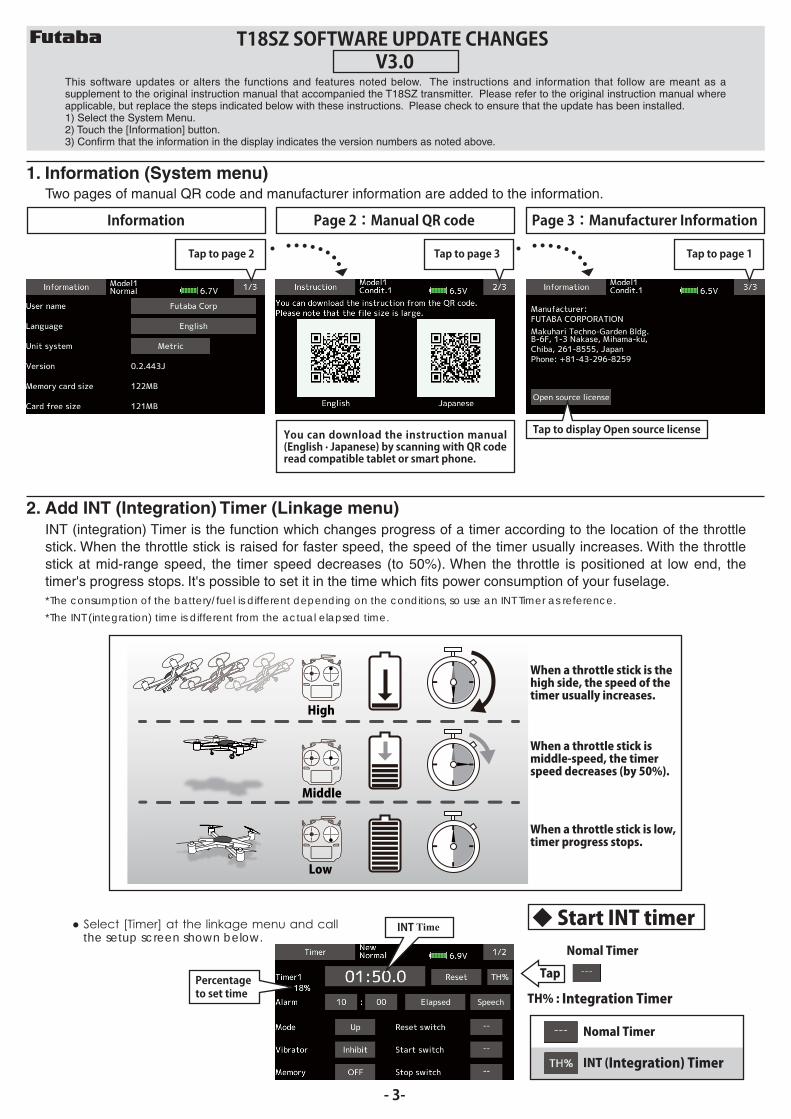
1. Information (System menu)Two pages of manual QR code and manufacturer information are added to the information.
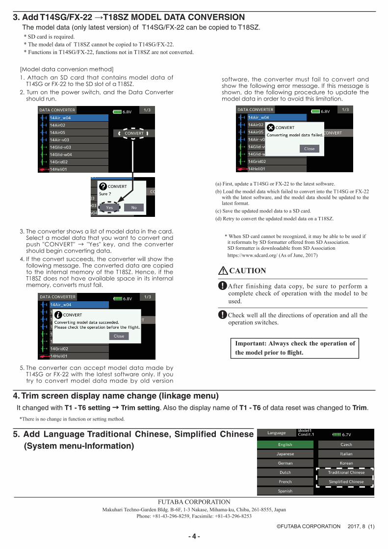
2. Add INT (Integration) Timer (Linkage menu)
T18SZ SOFTWARE UPDATE CHANGESV3.0
This software updates or alters the functions and features noted below. The instructions and information that follow are meant as a supplement to the original instruction manual that accompanied the T18SZ transmitter. Please refer to the original instruction manual where applicable, but replace the steps indicated below with these instructions. Please check to ensure that the update has been installed.1) Select the System Menu.2) Touch the [Information] button.3) Confirm that the information in the display indicates the version numbers as noted above.
Information Page 2:Manual QR code Page 3:Manufacturer Information
Tap to page 2 Tap to page 3 Tap to page 1
You can download the instruction manual(English · Japanese) by scanning with QR code read compatible tablet or smart phone.
INT (integration) Timer is the function which changes progress of a timer according to the location of the throttlestick. When the throttle stick is raised for faster speed, the speed of the timer usually increases. With the throttlestick at mid-range speed, the timer speed decreases (to 50%). When the throttle is positioned at low end, thetimer's progress stops. It's possible to set it in the time which fits power consumption of your fuselage.*The consumption of the battery/fuel is different depending on the conditions, so use an INT Timer as reference.
*The INT (integration) time is different from the actual elapsed time.
High
Middle
Low
When a throttle stick is the high side, the speed of the timer usually increases.
When a throttle stick is middle-speed, the timer speed decreases (by 50%).
When a throttle stick is low, timer progress stops.
Nomal Timer
Nomal Timer
TH% : Integration Timer
INT (Integration) Timer
the setup screen shown below.
TapPercentage to set time
INT Time◆ Start INT timer
Tap to display Open source license
- 4 -
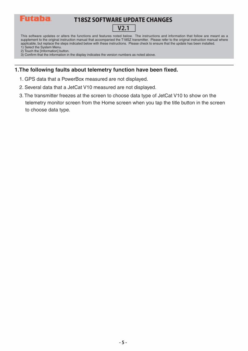
3. Add T14SG/FX-22 →T18SZ MODEL DATA CONVERSIONThe model data (only latest version) of T14SG/FX-22 can be copied to T18SZ.* SD card is required.* The model data of T18SZ cannot be copied to T14SG/FX-22.* Functions in T14SG/FX-22, functions not in T18SZ are not converted.
[Model data conversion method]1. Attach an SD card that contains model data of
T14SG or FX-22 to the SD slot of a T18SZ.2. Turn on the power switch, and the Data Converter
should run.
3. The converter shows a list of model data in the card.Select a model data that you want to convert andpush "CONVERT" → "Yes" key, and the convertershould begin converting data.
4. If the convert succeeds, the converter will show thefollowing message. The converted data are copiedto the internal memory of the T18SZ. Hence, if theT18SZ does not have available space in its internalmemory, converts must fail.
5. The converter can accept model data made byT14SG or FX-22 with the latest software only. If youtry to convert model data made by old version
* When SD card cannot be recognized, it may be able to be used ifit reformats by SD formatter offered from SD Association. SD formatter is downloadable from SD Associationhttps://www.sdcard.org/ (As of June, 2017)
CAUTION
After finishing data copy, be sure to perform a complete check of operation with the model to be used.
Check well all the directions of operation and all the operation switches.
software, the converter must fail to convert and show the following error message. If this message is shown, do the following procedure to update the model data in order to avoid this limitation.
(a) First, update a T14SG or FX-22 to the latest software.(b) Load the model data which failed to convert into the T14SG or FX-22
with the latest software, and the model data should be updated to thelatest format.
(c) Save the updated model data to a SD card.(d) Retry to convert the updated model data on a T18SZ.
FUTABA CORPORATIONMakuhari Techno-Garden Bldg. B-6F, 1-3 Nakase, Mihama-ku, Chiba, 261-8555, Japan
Phone: +81-43-296-8259, Facsimile: +81-43-296-8253
©FUTABA CORPORATION 2017, 8 (1)
Important: Always check the operation of the model prior to flight.
4.Trim screen display name change (linkage menu)It changed with T1 - T6 setting → Trim setting. Also the display name of T1 - T6 of data reset was changed to Trim.
*There is no change in function or setting method.
5. Add Language Traditional Chinese, Simplified Chinese(System menu-Information)
1.The following faults about telemetry function have been fixed.
1. GPS data that a PowerBox measured are not displayed.
2. Several data that a JetCat V10 measured are not displayed.
3. The transmitter freezes at the screen to choose data type of JetCat V10 to show on thetelemetry monitor screen from the Home screen when you tap the title button in the screento choose data type.
T18SZ SOFTWARE UPDATE CHANGESV2.1
This software updates or alters the functions and features noted below. The instructions and information that follow are meant as a supplement to the original instruction manual that accompanied the T18SZ transmitter. Please refer to the original instruction manual where applicable, but replace the steps indicated below with these instructions. Please check to ensure that the update has been installed.1) Select the System Menu.2) Touch the [Information] button.3) Confirm that the information in the display indicates the version numbers as noted above.
- 5 -
1.Vario Melody Setting
Vario Melody Setting is added to the variometer of the Altitude Sensor and GPS sensor.
Tap the [Set] button
Current variometer
This is the changing point of climb and sink. When the variometer is greater than this value, Vario Melody is climb type. When the variometer is less than this value, Vario Melody is sink type.Setting range:Range ↑ setting value ~ Range ↓ setting valueInitial value:0.0m/s
When the variometer is less than this value, Vario melody is notoutput.Setting range:0m/s ~ +50m/sInitial value:0.0m/s
When the variometer is greaterthan this value, Vario melody is notoutput.Setting range:-50m/s ~ 0m/sInitial value:0.0m/s
When the variometer is lessthan this value, Vario melody is not variable.Setting range:-50m/s ~ Offset valueInitial value:-5.0m/s
When the variometer is greaterthan this value, Vario melody is not variable.Setting range:Offset value ~ +50m/sInitial value:5.0m/s
*These settings can beset each sensors.
Dead band(Not sound)
Fixed melody
Fixed melody
Variable melody
Variable melody
Climd sideDiscontinuous sounds
Sink sideContinuoussounds
Range↑
Deadband↑
Deadband↓
Range↓
Offset
Offset
DeadbandRange
T18SZ SOFTWARE UPDATE CHANGESV2.0
This software updates or alters the functions and features noted below. The instructions and information that follow are meant as a supplement to the original instruction manual that accompanied the T18SZ transmitter. Please refer to the original instruction manual where applicable, but replace the steps indicated below with these instructions. Please check to ensure that the update has been installed.1) Select the System Menu.2) Touch the [Information] button.3) Confirm that the information in the display indicates the version numbers as noted above.
Next page
- 6 -
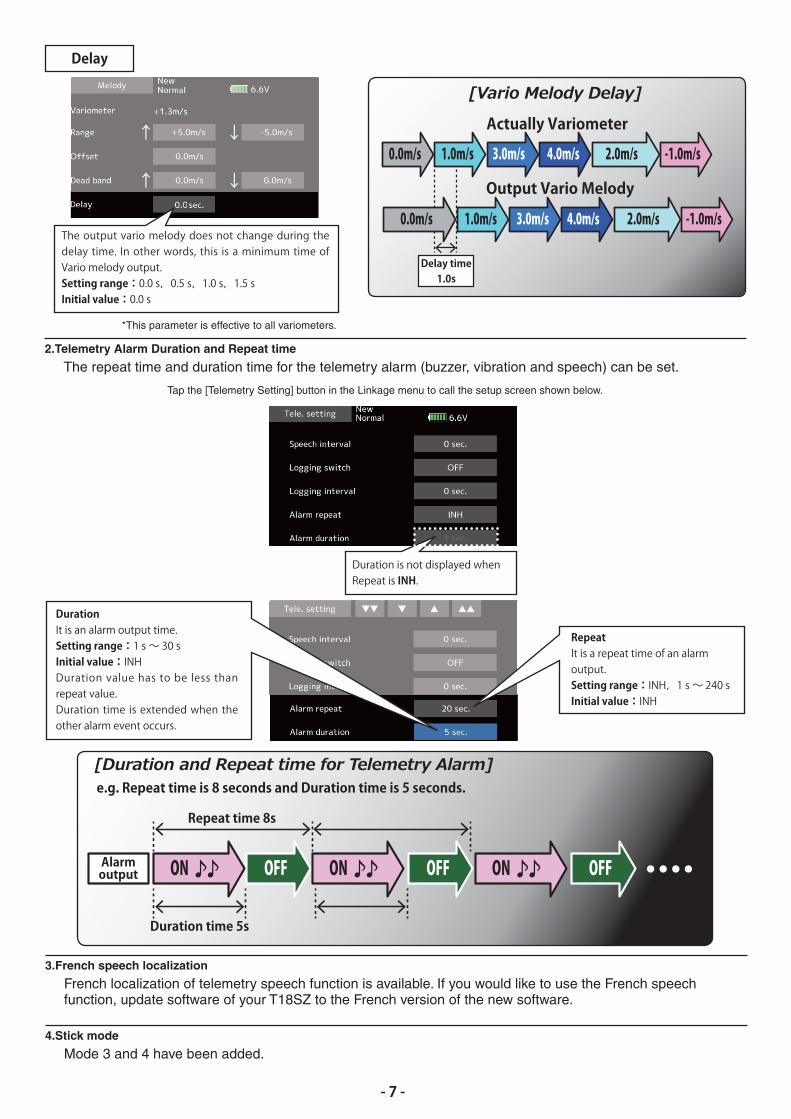
The output vario melody does not change during thedelay time. In other words, this is a minimum time ofVario melody output.Setting range:0.0 s,0.5 s,1.0 s,1.5 sInitial value:0.0 s
*This parameter is effective to all variometers.
2.Telemetry Alarm Duration and Repeat time
The repeat time and duration time for the telemetry alarm (buzzer, vibration and speech) can be set.
3.French speech localization
French localization of telemetry speech function is available. If you would like to use the French speechfunction, update software of your T18SZ to the French version of the new software.
Duration is not displayed whenRepeat is INH.
Delay
Actually Variometer
0.0m/s 1.0m/s 3.0m/s 4.0m/s -1.0m/s2.0m/s
Output Vario Melody
Delay time1.0s
0.0m/s 1.0m/s 3.0m/s 4.0m/s -1.0m/s2.0m/s
Alarmoutput
Duration time 5s
Repeat time 8s
OFF OFF OFFON ON ON
e.g. Repeat time is 8 seconds and Duration time is 5 seconds.
Tap the [Telemetry Setting] button in the Linkage menu to call the setup screen shown below.
DurationIt is an alarm output time.Setting range:1 s ~ 30 sInitial value:INHDuration value has to be less thanrepeat value.Duration time is extended when theother alarm event occurs.
RepeatIt is a repeat time of an alarm output.Setting range:INH,1 s ~ 240 sInitial value:INH
- 7 -
4.Stick mode
Mode 3 and 4 have been added.
T18SZ SOFTWARE UPDATE CHANGESV1.5 - V1.9
This software updates or alters the functions and features noted below. The instructions and information that follow are meant as a supplement to the original instruction manual that accompanied the T18SZ transmitter. Please refer to the original instruction manual where applicable, but replace the steps indicated below with these instructions. Please check to ensure that the update has been installed.1) Select the System Menu.2) Touch the [Information] button.3) Confirm that the information in the display indicates the version numbers as noted above.
- 8 -
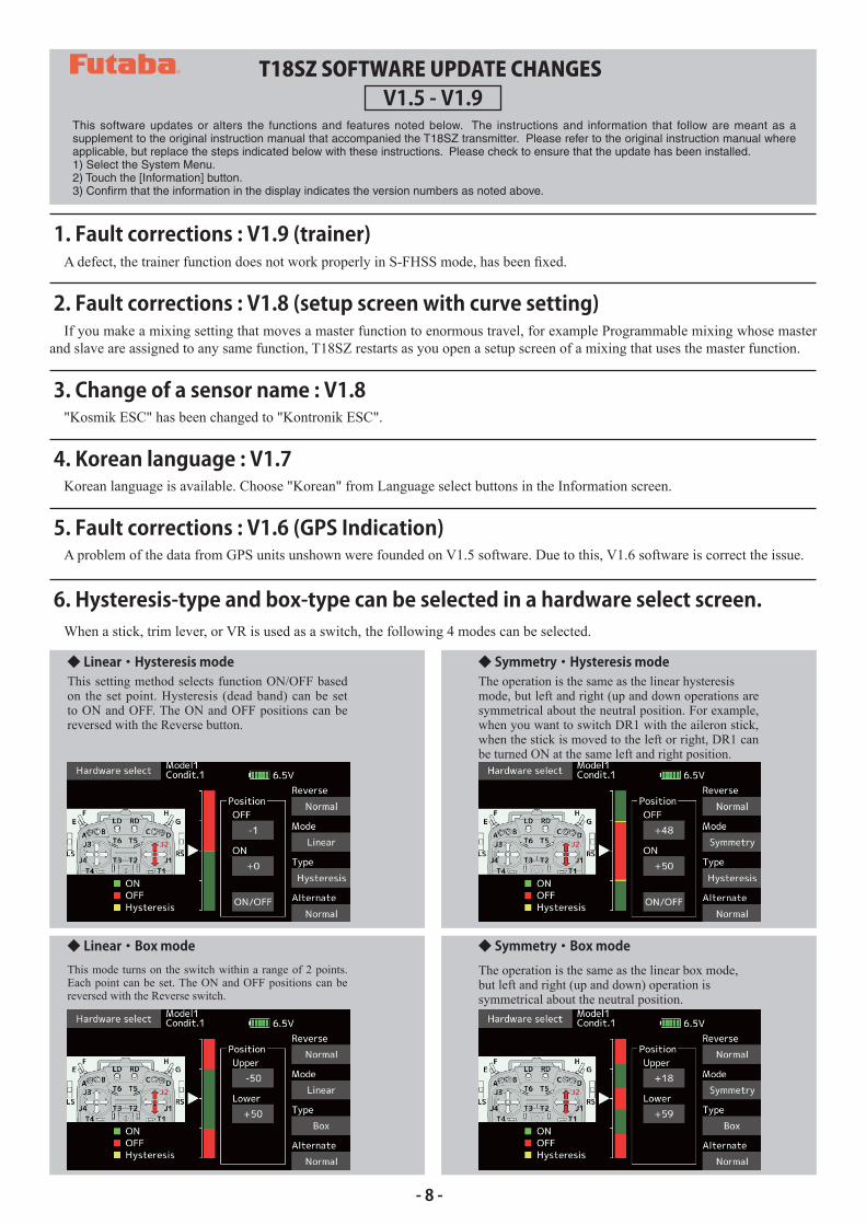
6. Hysteresis-type and box-type can be selected in a hardware select screen.
◆ Linear・Hysteresis mode ◆ Symmetry・Hysteresis mode
◆ Linear・Box mode
When a stick, trim lever, or VR is used as a switch, the following 4 modes can be selected.
This setting method selects function ON/OFF based on the set point. Hysteresis (dead band) can be set to ON and OFF. The ON and OFF positions can be reversed with the Reverse button.
The operation is the same as the linear hysteresismode, but left and right (up and down operations are symmetrical about the neutral position. For example, when you want to switch DR1 with the aileron stick, when the stick is moved to the left or right, DR1 can be turned ON at the same left and right position.
This mode turns on the switch within a range of 2 points. Each point can be set. The ON and OFF positions can be reversed with the Reverse switch.
◆ Symmetry・Box modeThe operation is the same as the linear box mode,but left and right (up and down) operation issymmetrical about the neutral position.
5. Fault corrections : V1.6 (GPS Indication)A problem of the data from GPS units unshown were founded on V1.5 software. Due to this, V1.6 software is correct the issue.
3. Change of a sensor name : V1.8"Kosmik ESC" has been changed to "Kontronik ESC".
2. Fault corrections : V1.8 (setup screen with curve setting)
1. Fault corrections : V1.9 (trainer)
4. Korean language : V1.7Korean language is available. Choose "Korean" from Language select buttons in the Information screen.
If you make a mixing setting that moves a master function to enormous travel, for example Programmable mixing whose master and slave are assigned to any same function, T18SZ restarts as you open a setup screen of a mixing that uses the master function.
- 9 -
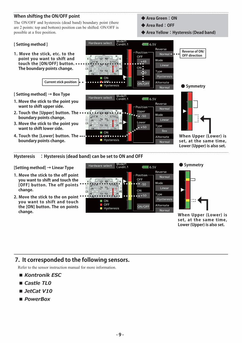
◆ Area Green:ON◆ Area Red:OFF◆ Area Yellow:Hysteresis (Dead band)
[ Setting method ]
[ Setting method] → Box Type
1. Move the stick, etc. to thepoint you want to shift andtouch the [ON/OFF] button.The boundary points change.
1. Move the stick to the point youwant to shift upper side.
3. Move the stick to the point youwant to shift lower side.
Current stick position
Reverse of ON/OFF direction
2. Touch the [Upper] button. Theboundary points change.
4. Touch the [Lower] button. Theboundary points change.
● Symmetry
● Symmetry
When shifting the ON/OFF pointThe ON/OFF and hysteresis (dead band) boundary point (there are 2 points: top and bottom) position can be shifted. ON/OFF is possible at a free position.
When Upper (Lower) isset, at the same time,Lower (Upper) is also set.
When Upper (Lower) isset, at the same time,Lower (Upper) is also set.
Hysteresis :Hysteresis (dead band) can be set to ON and OFF
[Setting method] → Linear Type
1. Move the stick to the off pointyou want to shift and touch the[OFF] button. The off pointschange.
2. Move the stick to the on pointyou want to shift and touchthe [ON] button. The on pointschange.
7. It corresponded to the following sensors.Refer to the sensor instruction manual for more information.
1. Curve setting operation
◆ Point addition method
◆ Point deletion method
Point curves or spline curves of up to 11/17 pointscan be used. (Initial value: 11/9 points)
decreased, and offset.
① Open the screen of a mixing curve with the curvefunction.
② Tap the [Remove] button. (The selected pointbecomes an outlined point□ )
③ Use the move between points button [← ] or[→ ].
*The point is deleted.
② Tap the "Position" button.
③ Tap the " ▼ ▼ " " ▼ " " ▲ " " ▲ ▲ " button andselect the position (mark □ ) you want to add.
① Use the move between points button [ ← ] or [ → ]and select the point. (The red
point ■ is the selected point.)
④ When the "Add" is tapped, the point is added.(□)→(■)*A new point is created.
⑤ Press "Rate" and use the up/down arrows to adjustthe rate points up or down.
The kind of mixing curve
The red point (■)moves (to green point) Move between
point
A red mark (□)moves freely
- 10 -
T18SZ SOFTWARE UPDATE CHANGESV1.4
This software updates or alters the functions and features noted below. The instructions and information that follow are meant as a supplement to the original instruction manual that accompanied the T18SZ transmitter. Please refer to the original instruction manual where applicable, but replace the steps indicated below with these instructions. Please check to ensure that the update has been installed.1) Select the System Menu.2) Touch the [Information] button.3) Confirm that the information in the display indicates the version numbers as noted above.
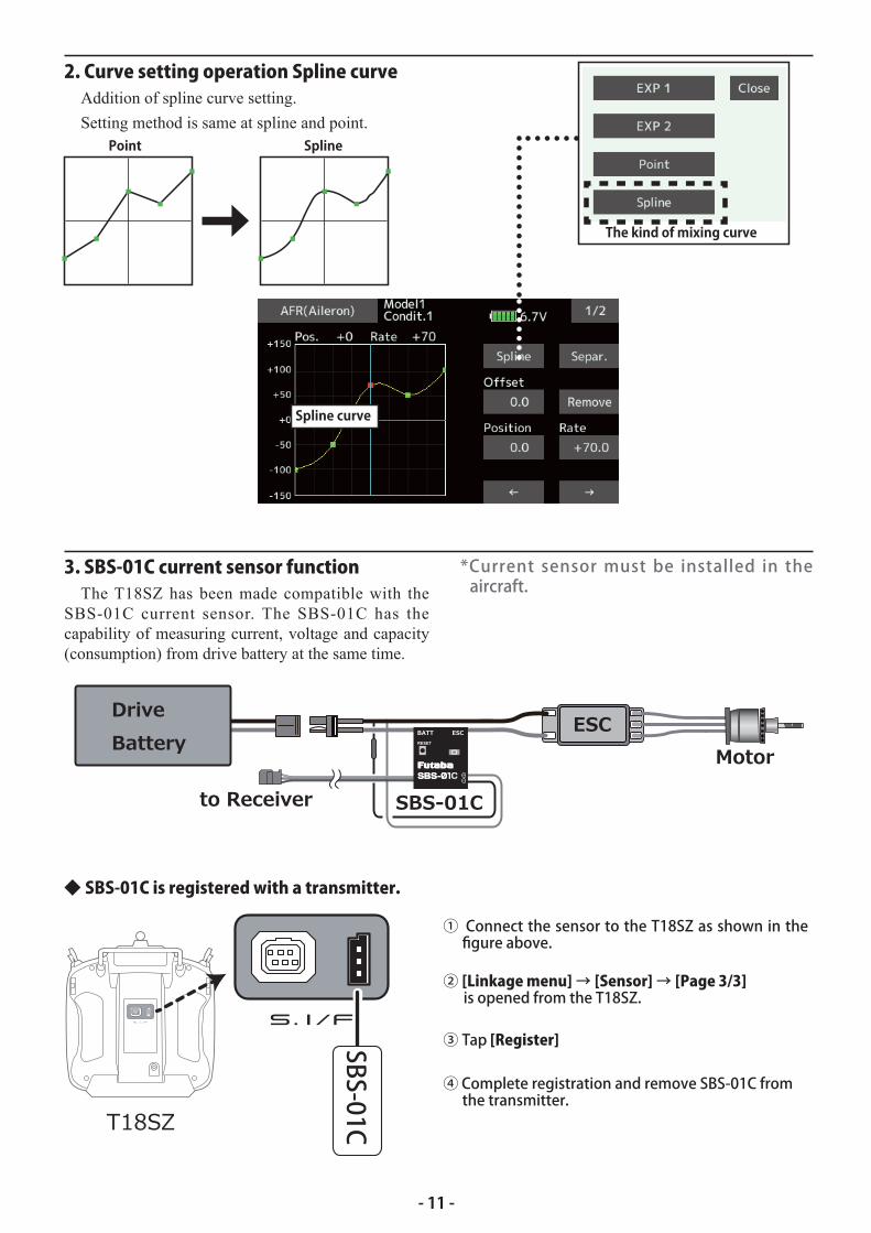
2. Curve setting operation Spline curve
3. SBS-01C current sensor function
Addition of spline curve setting.
Setting method is same at spline and point.
The T18SZ has been made compatible with theSBS-01C current sensor. The SBS-01C has the capability of measuring current, voltage and capacity (consumption) from drive battery at the same time.
Spline curve
◆ SBS-01C is registered with a transmitter.
① Connect the sensor to the T18SZ as shown in thefigure above.
② [Linkage menu]→ [Sensor]→ [Page 3/3]is opened from the T18SZ.
③ Tap [Register]
④ Complete registration and remove SBS-01C fromthe transmitter.
SBS-01C
The kind of mixing curve
Point Spline
*Current sensor must be installed in theaircraft.
- 11 -
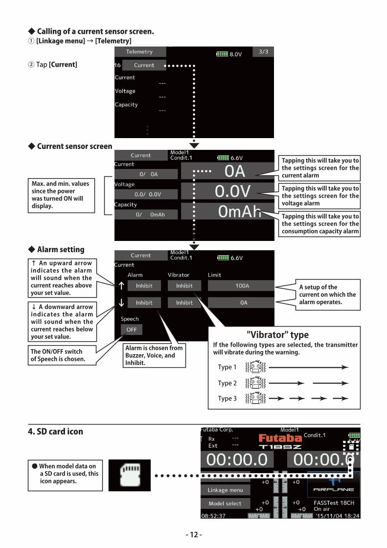
◆ Current sensor screen
◆ Alarm setting
4. SD card icon
◆ Calling of a current sensor screen.① [Linkage menu]→ [Telemetry]
② Tap [Current]
Max. and min. values since the power was turned ON will display.
A setup of the current on which the alarm operates.
Alarm is chosen from Buzzer, Voice, and Inhibit.
The ON/OFF switch of Speech is chosen.
Tapping this will take you to the settings screen for thecurrent alarm
Tapping this will take you to the settings screen for thevoltage alarm
Tapping this will take you to the settings screen for theconsumption capacity alarm
↑ An upward arrowindicates the alarmwill sound when thecurrent reaches above your set value.
↓ A downward arrowindicates the alarmwill sound when thecurrent reaches belowyour set value.
Type 1
Type 2
Type 3
"Vibrator" typeIf the following types are selected, the transmitterwill vibrate during the warning.
● When model data on a SD card is used, this icon appears.
- 12 -
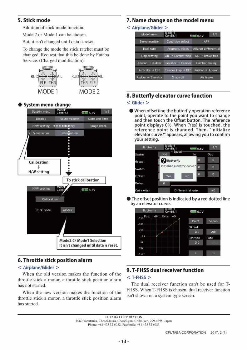
6. Throttle stick position alarm
9. T-FHSS dual receiver function
7. Name change on the model menu
8. Butterfly elevator curve function
< Airplane/Glider >
< T-FHSS >
< Airplane/Glider >
< Glider >
When the old version makes the function of the throttle stick a motor, a throttle stick position alarm has not started.
When the new version makes the function of the throttle stick a motor, a throttle stick position alarm has started.
The dual receiver function can't be used for T- FHSS. When T-FHSS is chosen, dual receiver function isn't shown on a system type screen.
● The offset position is indicated by a red dotted lineby an elevator curve.
5. Stick mode
Calibration↓
H/W setting
Mode2 ⇔ Mode1 SelectionIt isn't changed until data is reset.
◆ System menu change
To stick calibration
Addition of stick mode function.
Mode 2 or Mode 1 can be chosen.
But, it isn't changed until data is reset.
THRELERUD AIL
MODE 1ELETHR
RUD AIL
MODE 2
To change the mode the stick ratchet must bechanged. Request that this be done by Futaba
●When offsetting the butterfly operation referencepoint, operate to the point you want to changeand then touch the Offset button. The referencepoint displays 0%. When [Yes] is touched, thereference point is changed. Then, "Initializeelevator curve?" appears, allowing you to confirmyour setting.
FUTABA CORPORATION1080 Yabutsuka, Chosei-mura, Chosei-gun, Chiba-ken, 299-4395, Japan
Phone: +81 475 32 6982, Facsimile: +81 475 32 6983
- 13 -


![[RakutenTechConf2013][C-4_3] Our Goals and Activities at Rakuten Institute of Technology](https://img.pdfslide.net/doc/110x75/545cf151b1af9f460a8b48d8/rakutentechconf2013c-43-our-goals-and-activities-at-rakuten-institute-of-technology.jpg)