Embed Size (px)
Citation preview
1
Table of Contents
Introduction ..............................................................................2
PLCs ..........................................................................................4
Number Systems .....................................................................8
Terminology ...........................................................................14
Basic Requirements ...............................................................23
S7-200 Micro PLCs.................................................................28
Connecting External Devices ................................................39
Programming A PLC ..............................................................41
Discrete Inputs/Outputs.........................................................52
Analog Inputs and Outputs ...................................................65
Timers .....................................................................................68
Counters .................................................................................75
High-Speed Instructions ........................................................80
Review Answers ....................................................................84
Final Exam ..............................................................................85
2
Introduction
Welcome to another course in the STEP 2000 series,Siemens Technical Education Program, designed to prepareour distributors to sell Siemens Energy & Automationproducts more effectively. This course covers Basics of PLCsand related products.
Upon completion of Basics of PLCs you should be able to:
� Identify the major components of a PLC and describetheir functions
� Convert numbers from decimal to binary, BCD, andhexadecimal
� Identify typical discrete and analog inputs and outputs
� Read a basic ladder logic diagram and statement list
� Identify operational differences between the S7-212and S7-214
� Identify the proper manual to refer to for programmingor installation of an S7-200 PLC
� Connect a simple discrete input and output to anS7-200
� Select the proper expansion module for analog inputsand outputs
� Describe the operation of timers and counters
3
This knowledge will help you better understand customerapplications. In addition, you will be better able to describeproducts to customers and determine important differencesbetween products. You should complete Basics of Electricitybefore attempting Basics of PLCs. An understanding of manyof the concepts covered in Basics of Electricity is requiredfor Basics of PLCs. In addition you may wish to completeBasics of Control Components. Devices covered in Basics ofControl Components are used with programmable logiccontrollers.
If you are an employee of a Siemens Energy & Automationauthorized distributor, fill out the final exam tear-out card andmail in the card. We will mail you a certificate of completion ifyou score a passing grade. Good luck with your efforts.
SIMATIC, STEP 7, STEP 7-Micro, STEP 7-Micro/DOS, STEP 7-Micro/WIN, PG 702, and PG 740 are registered trademarks ofSiemens Energy & Automation, Inc.
MS-DOS and Windows are trademarks of Microsoft, Inc.
4
PLCs
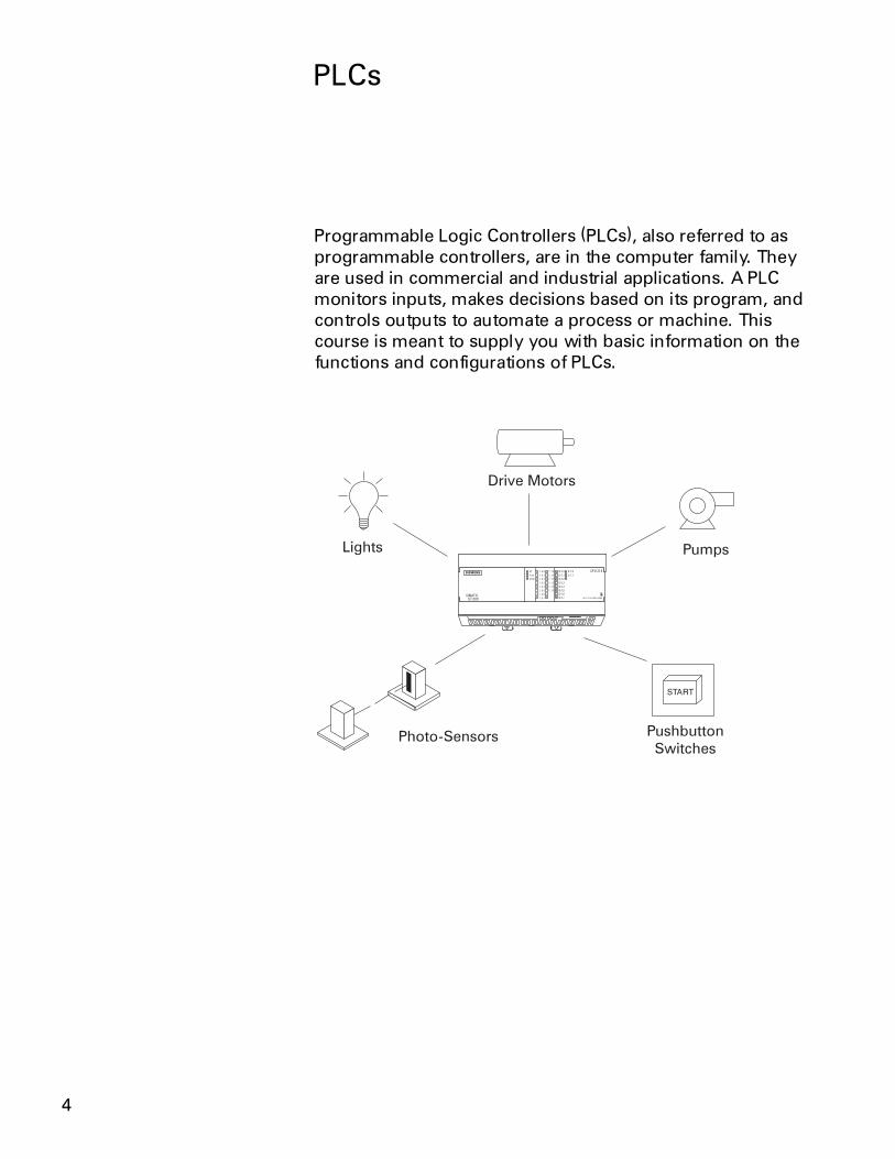
Programmable Logic Controllers (PLCs), also referred to asprogrammable controllers, are in the computer family. Theyare used in commercial and industrial applications. A PLCmonitors inputs, makes decisions based on its program, andcontrols outputs to automate a process or machine. Thiscourse is meant to supply you with basic information on thefunctions and configurations of PLCs.
5
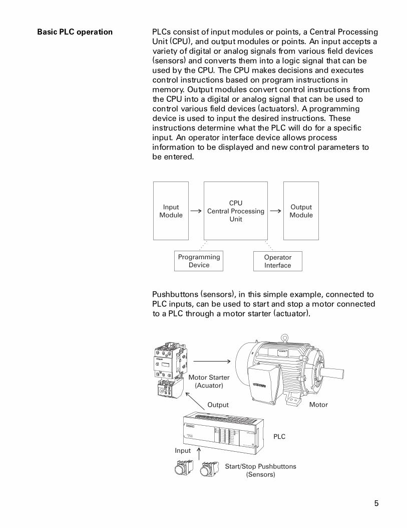
Basic PLC operation PLCs consist of input modules or points, a Central ProcessingUnit (CPU), and output modules or points. An input accepts avariety of digital or analog signals from various field devices(sensors) and converts them into a logic signal that can beused by the CPU. The CPU makes decisions and executescontrol instructions based on program instructions inmemory. Output modules convert control instructions fromthe CPU into a digital or analog signal that can be used tocontrol various field devices (actuators). A programmingdevice is used to input the desired instructions. Theseinstructions determine what the PLC will do for a specificinput. An operator interface device allows processinformation to be displayed and new control parameters tobe entered.
Input
Module
Output
Module
CPU
Central Processing
Unit
Programming
Device
Operator
Interface
Pushbuttons (sensors), in this simple example, connected toPLC inputs, can be used to start and stop a motor connectedto a PLC through a motor starter (actuator).
6
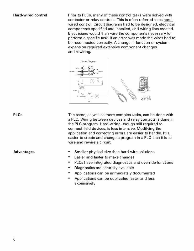
Hard-wired control Prior to PLCs, many of these control tasks were solved withcontactor or relay controls. This is often referred to as hard-wired control. Circuit diagrams had to be designed, electricalcomponents specified and installed, and wiring lists created.Electricians would then wire the components necessary toperform a specific task. If an error was made the wires had tobe reconnected correctly. A change in function or systemexpansion required extensive component changesand rewiring.
OL
M
CR
CR
L1T1
T2
T3
L2
L3
OL
OL
OL
M
M
CR
MMotor
StartStop
460 VAC
24 VAC
1
2
PLCs The same, as well as more complex tasks, can be done witha PLC. Wiring between devices and relay contacts is done inthe PLC program. Hard-wiring, though still required toconnect field devices, is less intensive. Modifying theapplication and correcting errors are easier to handle. It iseasier to create and change a program in a PLC than it is towire and rewire a circuit.
� Smaller physical size than hard-wire solutions� Easier and faster to make changes� PLCs have integrated diagnostics and override functions� Diagnostics are centrally available� Applications can be immediately documented� Applications can be duplicated faster and less
expensively
Advantages
7
Siemens PLCs Siemens makes several PLC product lines in the SIMATIC® S7family. They are: S7-200, S7-300, and S7-400.
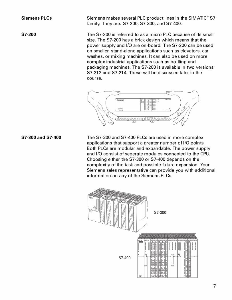
S7-200 The S7-200 is referred to as a micro PLC because of its smallsize. The S7-200 has a brick design which means that thepower supply and I/O are on-board. The S7-200 can be usedon smaller, stand-alone applications such as elevators, carwashes, or mixing machines. It can also be used on morecomplex industrial applications such as bottling andpackaging machines. The S7-200 is available in two versions:S7-212 and S7-214. These will be discussed later in thecourse.
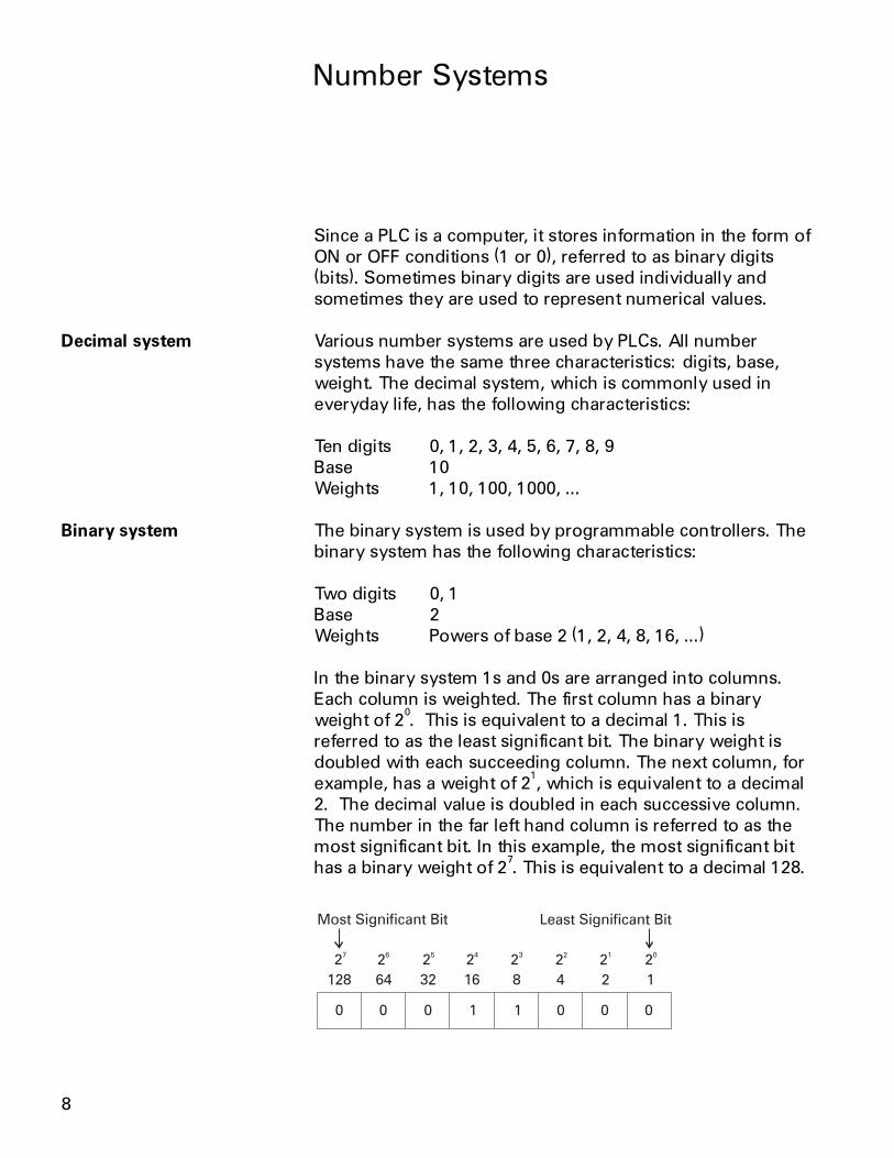
S7-300 and S7-400 The S7-300 and S7-400 PLCs are used in more complexapplications that support a greater number of I/O points.Both PLCs are modular and expandable. The power supplyand I/O consist of seperate modules connected to the CPU.Choosing either the S7-300 or S7-400 depends on thecomplexity of the task and possible future expansion. YourSiemens sales representative can provide you with additionalinformation on any of the Siemens PLCs.
8
Number Systems
Since a PLC is a computer, it stores information in the form ofON or OFF conditions (1 or 0), referred to as binary digits(bits). Sometimes binary digits are used individually andsometimes they are used to represent numerical values.
Decimal system Various number systems are used by PLCs. All numbersystems have the same three characteristics: digits, base,weight. The decimal system, which is commonly used ineveryday life, has the following characteristics:
Ten digits 0, 1, 2, 3, 4, 5, 6, 7, 8, 9Base 10Weights 1, 10, 100, 1000, ...
Binary system The binary system is used by programmable controllers. Thebinary system has the following characteristics:
Two digits 0, 1Base 2Weights Powers of base 2 (1, 2, 4, 8, 16, ...)
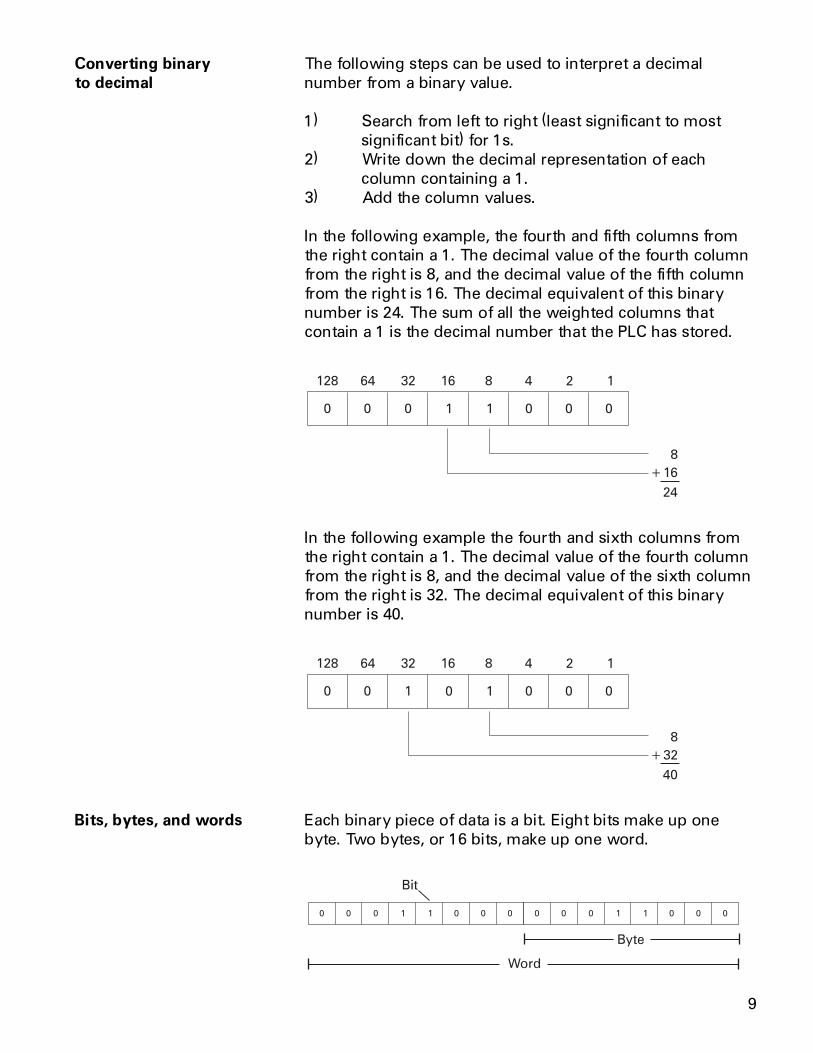
In the binary system 1s and 0s are arranged into columns.Each column is weighted. The first column has a binaryweight of 2
0. This is equivalent to a decimal 1. This is
referred to as the least significant bit. The binary weight isdoubled with each succeeding column. The next column, forexample, has a weight of 2
1, which is equivalent to a decimal
2. The decimal value is doubled in each successive column.The number in the far left hand column is referred to as themost significant bit. In this example, the most significant bithas a binary weight of 2
7. This is equivalent to a decimal 128.
128 64 32 16 8 4 2 1
0 0 0 1 1 0 0 0
Most Significant Bit Least Significant Bit
27
26
25
24
23
22
21
20
9
Converting binary The following steps can be used to interpret a decimalto decimal number from a binary value.
1) Search from left to right (least significant to mostsignificant bit) for 1s.
2) Write down the decimal representation of eachcolumn containing a 1.
3) Add the column values.
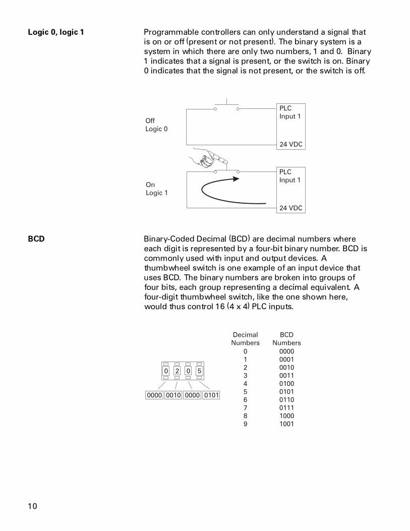
In the following example, the fourth and fifth columns fromthe right contain a 1. The decimal value of the fourth columnfrom the right is 8, and the decimal value of the fifth columnfrom the right is 16. The decimal equivalent of this binarynumber is 24. The sum of all the weighted columns thatcontain a 1 is the decimal number that the PLC has stored.
128 64 32 16 8 4 2 1
0 0 0 1 1 0 0 0
8
16
24
+
In the following example the fourth and sixth columns fromthe right contain a 1. The decimal value of the fourth columnfrom the right is 8, and the decimal value of the sixth columnfrom the right is 32. The decimal equivalent of this binarynumber is 40.
128 64 32 16 8 4 2 1
0 0 1 0 1 0 0 0
8
32
40
+
Bits, bytes, and words Each binary piece of data is a bit. Eight bits make up onebyte. Two bytes, or 16 bits, make up one word.
0 0 0 1 1 0 0 0 0 0 0 1 1 0 0 0
Byte
Word
Bit
10
Logic 0, logic 1 Programmable controllers can only understand a signal thatis on or off (present or not present). The binary system is asystem in which there are only two numbers, 1 and 0. Binary1 indicates that a signal is present, or the switch is on. Binary0 indicates that the signal is not present, or the switch is off.
BCD Binary-Coded Decimal (BCD) are decimal numbers whereeach digit is represented by a four-bit binary number. BCD iscommonly used with input and output devices. Athumbwheel switch is one example of an input device thatuses BCD. The binary numbers are broken into groups offour bits, each group representing a decimal equivalent. Afour-digit thumbwheel switch, like the one shown here,would thus control 16 (4 x 4) PLC inputs.
0 2 0 5
Decimal
Numbers
BCD
Numbers
0
1
2
3
4
5
6
7
8
9
0000
0001
0010
0011
0100
0101
0110
0111
1000
1001
0000 0010 0000 0101
11
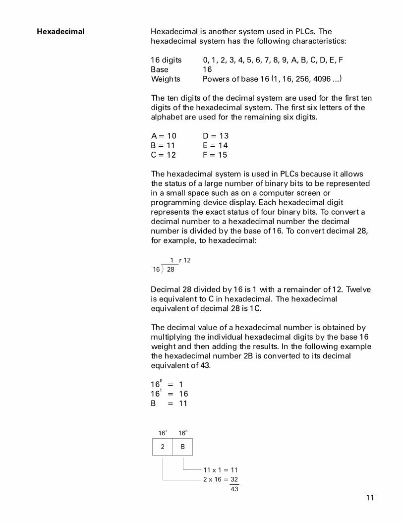
Hexadecimal Hexadecimal is another system used in PLCs. Thehexadecimal system has the following characteristics:
16 digits 0, 1, 2, 3, 4, 5, 6, 7, 8, 9, A, B, C, D, E, FBase 16Weights Powers of base 16 (1, 16, 256, 4096 ...)
The ten digits of the decimal system are used for the first tendigits of the hexadecimal system. The first six letters of thealphabet are used for the remaining six digits.
A = 10 D = 13B = 11 E = 14C = 12 F = 15
The hexadecimal system is used in PLCs because it allowsthe status of a large number of binary bits to be representedin a small space such as on a computer screen orprogramming device display. Each hexadecimal digitrepresents the exact status of four binary bits. To convert adecimal number to a hexadecimal number the decimalnumber is divided by the base of 16. To convert decimal 28,for example, to hexadecimal:
16 28
1 r 12
Decimal 28 divided by 16 is 1 with a remainder of 12. Twelveis equivalent to C in hexadecimal. The hexadecimalequivalent of decimal 28 is 1C.
The decimal value of a hexadecimal number is obtained bymultiplying the individual hexadecimal digits by the base 16weight and then adding the results. In the following examplethe hexadecimal number 2B is converted to its decimalequivalent of 43.
160
= 116
1= 16
B = 11
160
161
2 x 16 = 32
11 x 1 = 11
43
2 B
12
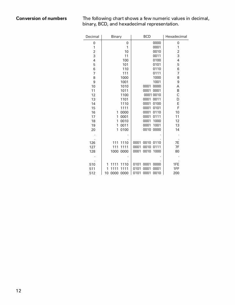
Conversion of numbers The following chart shows a few numeric values in decimal,binary, BCD, and hexadecimal representation.
0
1
2
3
4
5
6
7
8
9
10
11
12
13
14
15
16
17
18
19
20
.
.
126
127
128
.
.
510
511
512
Decimal
0
1
10
11
100
101
110
111
1000
1001
1010
1011
1100
1101
1110
1111
1 0000
1 0001
1 0010
1 0011
1 0100
.
.
111 1110
111 1111
1000 0000
.
.
1 1111 1110
1 1111 1111
10 0000 0000
Binary
0
1
2
3
4
5
6
7
8
9
A
B
C
D
E
F
10
11
12
13
14
.
.
7E
7F
80
.
.
1FE
1FF
200
Hexadecimal
0000
0001
0010
0011
0100
0101
0110
0111
1000
1001
0001 0000
0001 0001
0001 0010
0001 0011
0001 0100
0001 0101
0001 0110
0001 0111
0001 1000
0001 1001
0010 0000
.
.
0001 0010 0110
0001 0010 0111
0001 0010 1000
.
.
0101 0001 0000
0101 0001 0001
0101 0001 0010
BCD
13
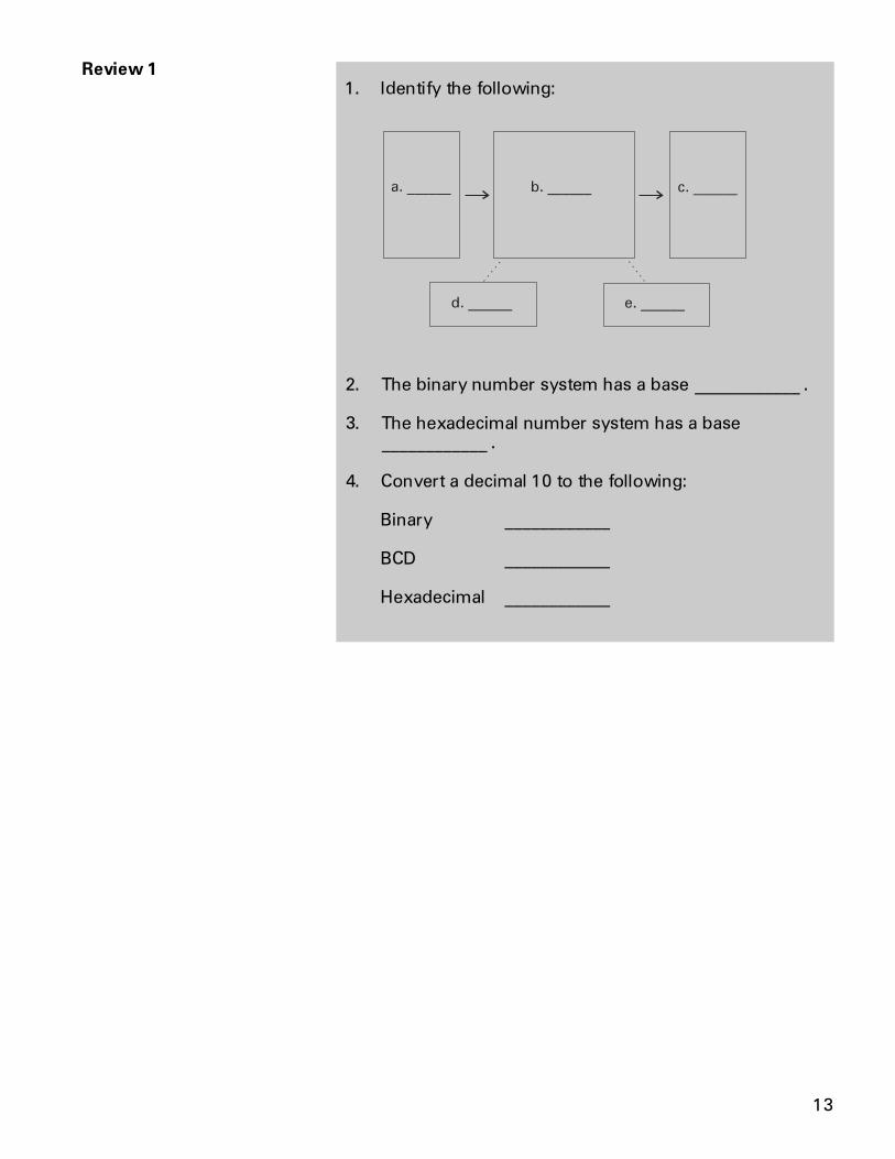
Review 11. Identify the following:
a. ______ b. ______ c. ______
d. ______ e. ______
2. The binary number system has a base ____________ .
3. The hexadecimal number system has a base____________ .
4. Convert a decimal 10 to the following:
Binary ____________
BCD ____________
Hexadecimal ____________
14
Terminology
The language of PLCs consists of a commonly used set ofterms; many of which are unique to PLCs. In order tounderstand the ideas and concepts of PLCs, anunderstanding of these terms is necessary.
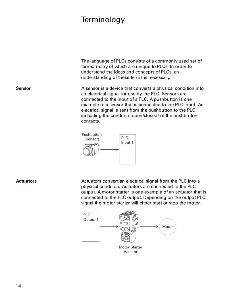
Sensor A sensor is a device that converts a physical condition intoan electrical signal for use by the PLC. Sensors areconnected to the input of a PLC. A pushbutton is oneexample of a sensor that is connected to the PLC input. Anelectrical signal is sent from the pushbutton to the PLCindicating the conditon (open/closed) of the pushbuttoncontacts.
Actuators Actuators convert an electrical signal from the PLC into aphysical condition. Actuators are connected to the PLCoutput. A motor starter is one example of an actuator that isconnected to the PLC output. Depending on the output PLCsignal the motor starter will either start or stop the motor.
15
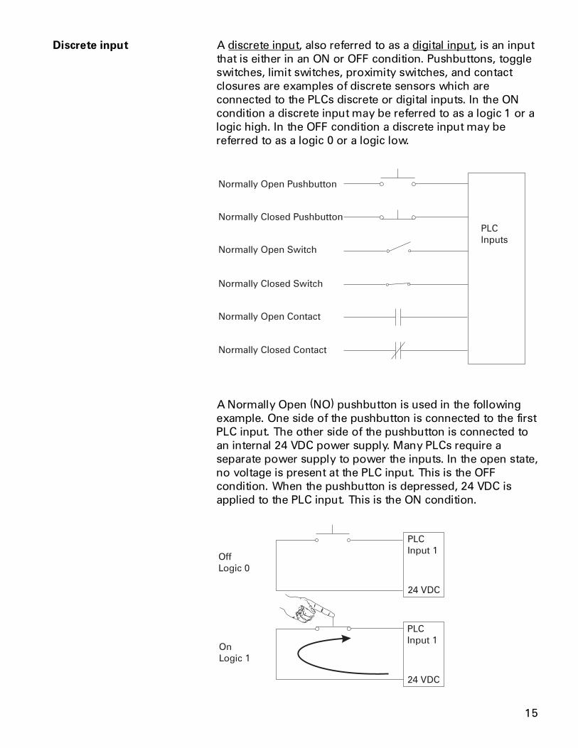
Discrete input A discrete input, also referred to as a digital input, is an inputthat is either in an ON or OFF condition. Pushbuttons, toggleswitches, limit switches, proximity switches, and contactclosures are examples of discrete sensors which areconnected to the PLCs discrete or digital inputs. In the ONcondition a discrete input may be referred to as a logic 1 or alogic high. In the OFF condition a discrete input may bereferred to as a logic 0 or a logic low.
PLC
Inputs
Normally Open Pushbutton
Normally Closed Pushbutton
Normally Closed Switch
Normally Closed Contact
Normally Open Switch
Normally Open Contact
A Normally Open (NO) pushbutton is used in the followingexample. One side of the pushbutton is connected to the firstPLC input. The other side of the pushbutton is connected toan internal 24 VDC power supply. Many PLCs require aseparate power supply to power the inputs. In the open state,no voltage is present at the PLC input. This is the OFFcondition. When the pushbutton is depressed, 24 VDC isapplied to the PLC input. This is the ON condition.
16
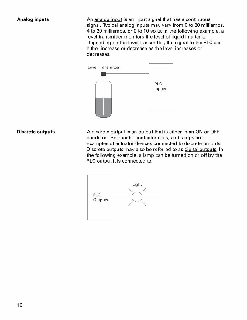
Analog inputs An analog input is an input signal that has a continuoussignal. Typical analog inputs may vary from 0 to 20 milliamps,4 to 20 milliamps, or 0 to 10 volts. In the following example, alevel transmitter monitors the level of liquid in a tank.Depending on the level transmitter, the signal to the PLC caneither increase or decrease as the level increases ordecreases.
PLC
Inputs
Level Transmitter
Discrete outputs A discrete output is an output that is either in an ON or OFFcondition. Solenoids, contactor coils, and lamps areexamples of actuator devices connected to discrete outputs.Discrete outputs may also be referred to as digital outputs. Inthe following example, a lamp can be turned on or off by thePLC output it is connected to.
PLC
Outputs
Light
17
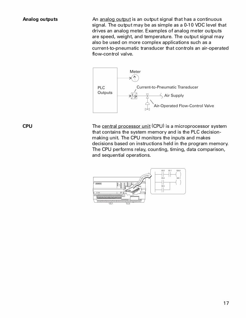
Analog outputs An analog output is an output signal that has a continuoussignal. The output may be as simple as a 0-10 VDC level thatdrives an analog meter. Examples of analog meter outputsare speed, weight, and temperature. The output signal mayalso be used on more complex applications such as acurrent-to-pneumatic transducer that controls an air-operatedflow-control valve.
CPU The central processor unit (CPU) is a microprocessor systemthat contains the system memory and is the PLC decision-making unit. The CPU monitors the inputs and makesdecisions based on instructions held in the program memory.The CPU performs relay, counting, timing, data comparison,and sequential operations.
I0.0 Q0.0
Q0.1
I0.1
I0.4
I0.5
18
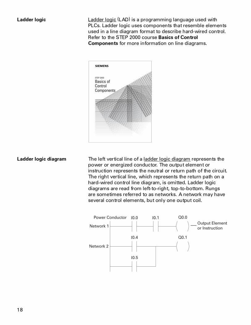
Ladder logic Ladder logic (LAD) is a programming language used withPLCs. Ladder logic uses components that resemble elementsused in a line diagram format to describe hard-wired control.Refer to the STEP 2000 course Basics of ControlComponents for more information on line diagrams.
STEP 2000
Basics ofControlComponents
Ladder logic diagram The left vertical line of a ladder logic diagram represents thepower or energized conductor. The output element orinstruction represents the neutral or return path of the circuit.The right vertical line, which represents the return path on ahard-wired control line diagram, is omitted. Ladder logicdiagrams are read from left-to-right, top-to-bottom. Rungsare sometimes referred to as networks. A network may haveseveral control elements, but only one output coil.
I0.0 I0.1
I0.4
I0.5
Q0.1
Q0.0Power Conductor
Output Element
or InstructionNetwork 1
Network 2
19
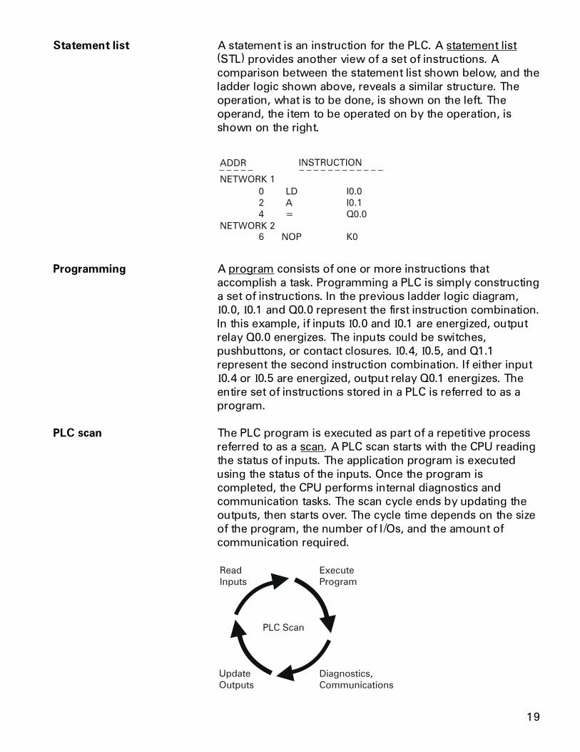
Statement list A statement is an instruction for the PLC. A statement list(STL) provides another view of a set of instructions. Acomparison between the statement list shown below, and theladder logic shown above, reveals a similar structure. Theoperation, what is to be done, is shown on the left. Theoperand, the item to be operated on by the operation, isshown on the right.
Programming A program consists of one or more instructions thataccomplish a task. Programming a PLC is simply constructinga set of instructions. In the previous ladder logic diagram,I0.0, I0.1 and Q0.0 represent the first instruction combination.In this example, if inputs I0.0 and I0.1 are energized, outputrelay Q0.0 energizes. The inputs could be switches,pushbuttons, or contact closures. I0.4, I0.5, and Q1.1represent the second instruction combination. If either inputI0.4 or I0.5 are energized, output relay Q0.1 energizes. Theentire set of instructions stored in a PLC is referred to as aprogram.
PLC scan The PLC program is executed as part of a repetitive processreferred to as a scan. A PLC scan starts with the CPU readingthe status of inputs. The application program is executedusing the status of the inputs. Once the program iscompleted, the CPU performs internal diagnostics andcommunication tasks. The scan cycle ends by updating theoutputs, then starts over. The cycle time depends on the sizeof the program, the number of I/Os, and the amount ofcommunication required.
PLC Scan
Read
Inputs
Update
Outputs
Diagnostics,
Communications
Execute
Program
20
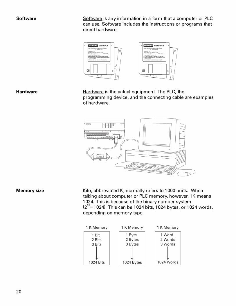
Software Software is any information in a form that a computer or PLCcan use. Software includes the instructions or programs thatdirect hardware.
Hardware Hardware is the actual equipment. The PLC, theprogramming device, and the connecting cable are examplesof hardware.
Memory size Kilo, abbreviated K, normally refers to 1000 units. Whentalking about computer or PLC memory, however, 1K means1024. This is because of the binary number system(2
10=1024). This can be 1024 bits, 1024 bytes, or 1024 words,
depending on memory type.
1 Bit
2 Bits
3 Bits
1 Byte
2 Bytes
3 Bytes
1 Word
2 Words
3 Words
1024 Words1024 Bytes1024 Bits
1 K Memory 1 K Memory 1 K Memory
21
RAM Random Access Memory (RAM) is memory where data canbe directly accessed at any address. Data can be written toand read from RAM. RAM is used as a temporary storagearea. RAM is volatile, meaning that the data stored in RAMwill be lost if power is lost. A battery backup is required toavoid losing data in the event of a power loss.
ROM Read Only Memory (ROM) is a type of memory that data canbe read from but not written to. This type of memory is usedto protect data or programs from accidental erasure. ROMmemory is nonvolatile. This means a user program will notlose data during a loss of electrical power. ROM is normallyused to store the programs that define the capabilities of thePLC.
EPROM Erasable Programmable Read Only Memory (EPROM)provides some level of security against unauthorized orunwanted changes in a program. EPROMs are designed sothat data stored in them can be read, but not easily altered.Changing EPROM data requires a special effort. UVEPROMs(ultraviolet erasable programmable read only memory) canonly be erased with an ultraviolet light. EEPROM(electronically erasable programmable read only memory),can only be erased electronically.
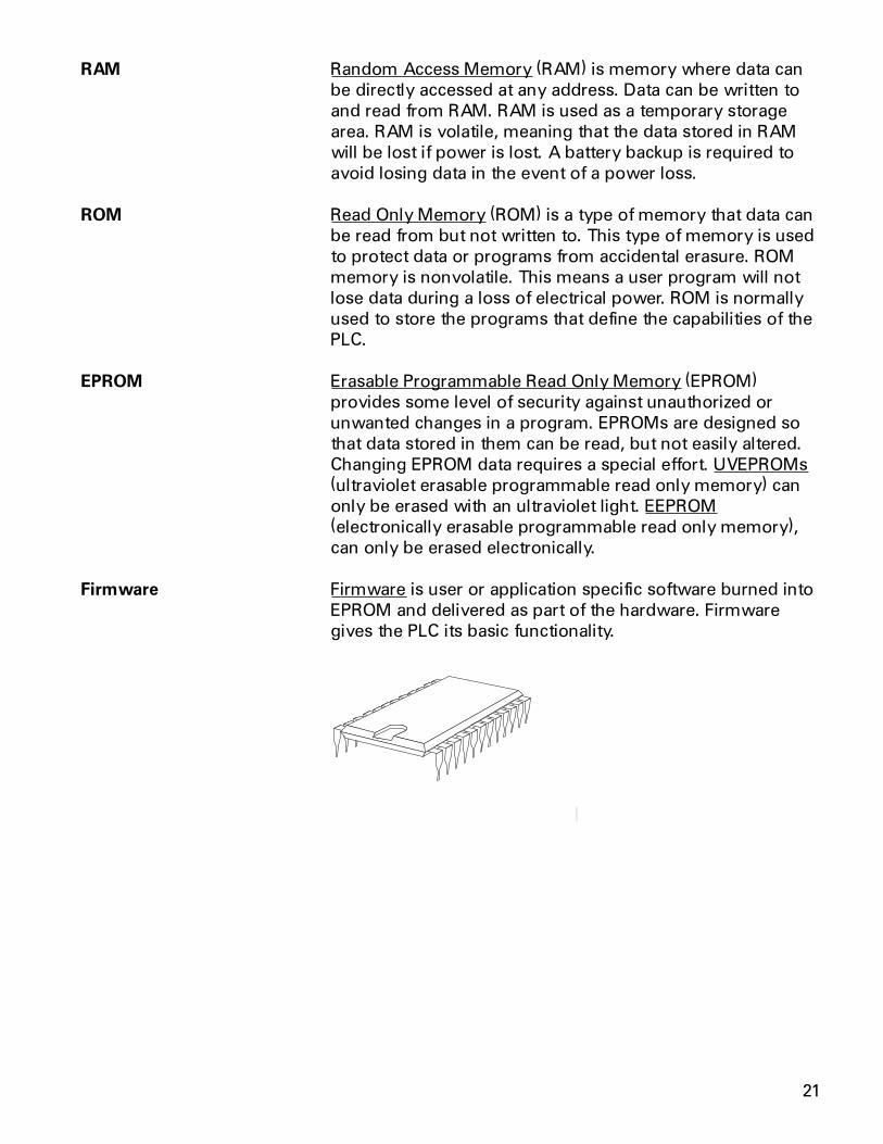
Firmware Firmware is user or application specific software burned intoEPROM and delivered as part of the hardware. Firmwaregives the PLC its basic functionality.
22
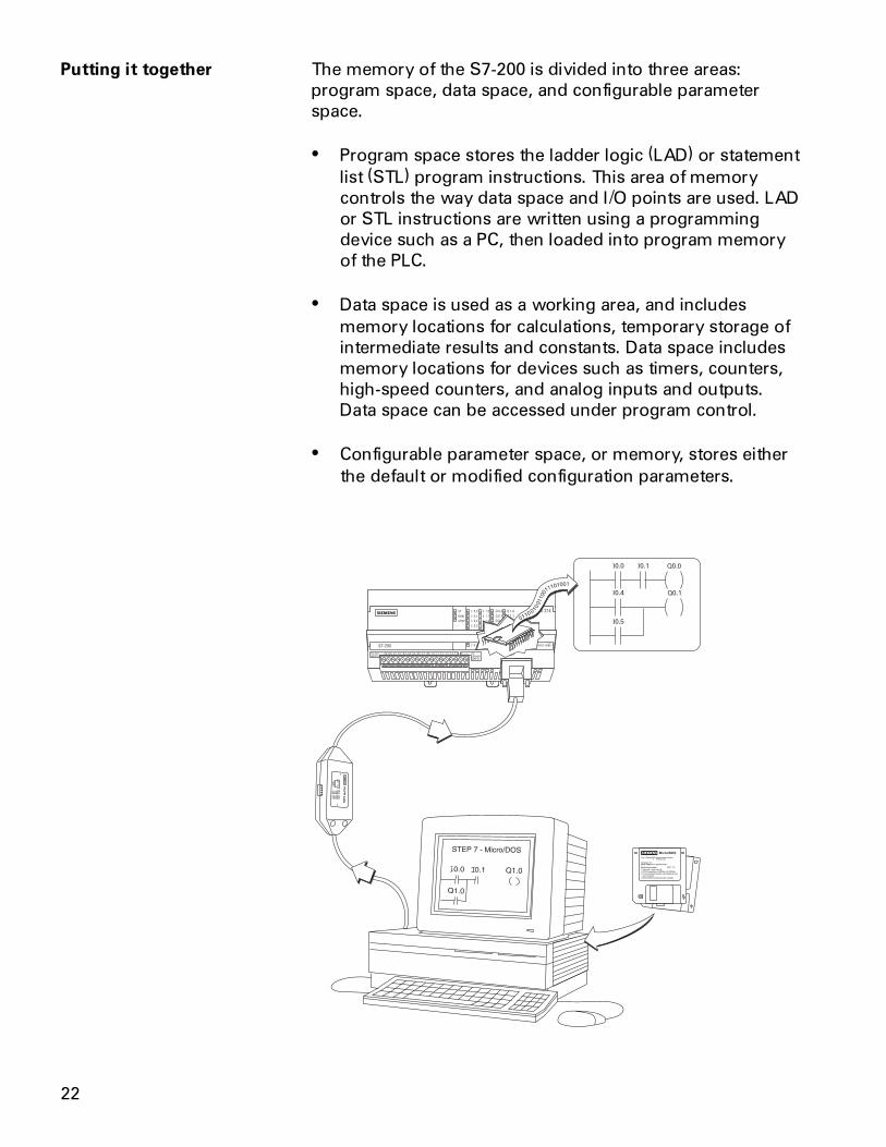
Putting it together The memory of the S7-200 is divided into three areas:program space, data space, and configurable parameterspace.
� Program space stores the ladder logic (LAD) or statementlist (STL) program instructions. This area of memorycontrols the way data space and I/O points are used. LADor STL instructions are written using a programmingdevice such as a PC, then loaded into program memoryof the PLC.
� Data space is used as a working area, and includesmemory locations for calculations, temporary storage ofintermediate results and constants. Data space includesmemory locations for devices such as timers, counters,high-speed counters, and analog inputs and outputs.Data space can be accessed under program control.
� Configurable parameter space, or memory, stores eitherthe default or modified configuration parameters.
23
Basic Requirements
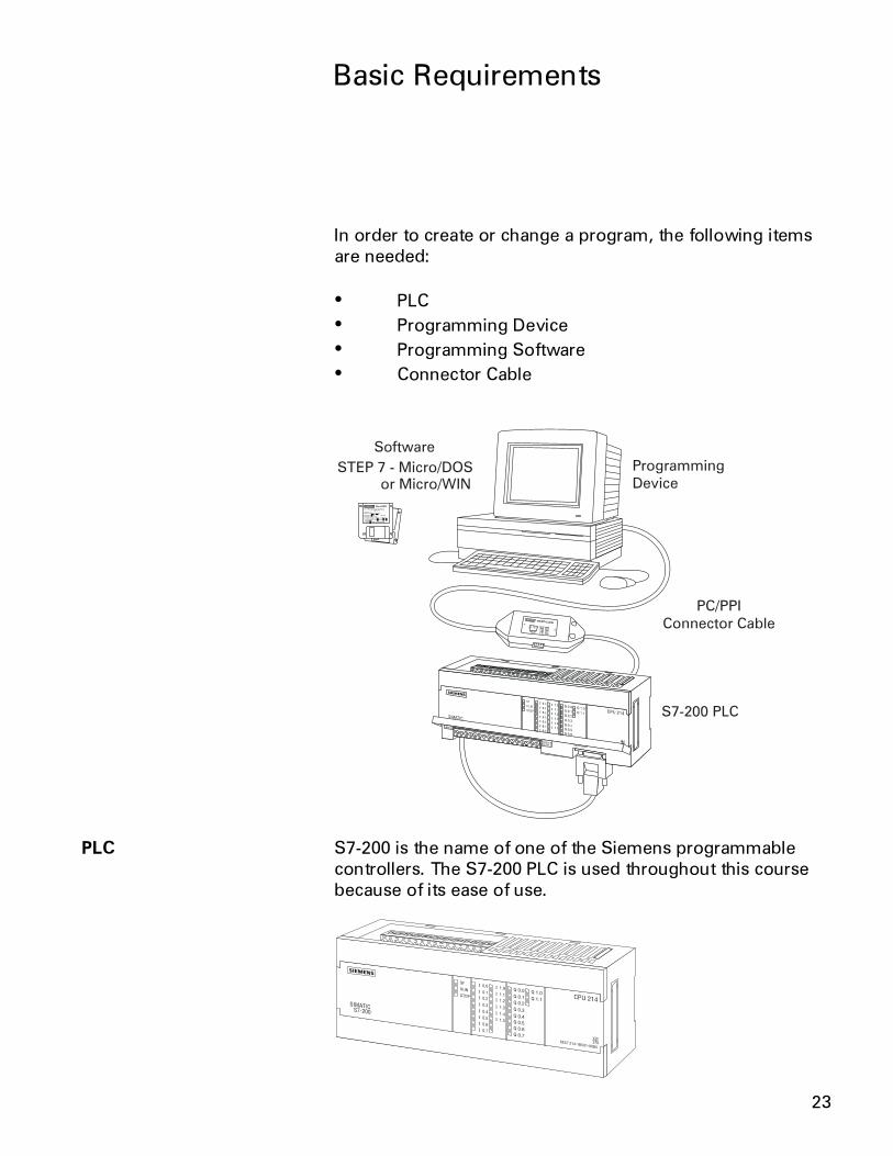
In order to create or change a program, the following itemsare needed:
� PLC� Programming Device� Programming Software� Connector Cable
PLC S7-200 is the name of one of the Siemens programmablecontrollers. The S7-200 PLC is used throughout this coursebecause of its ease of use.
24
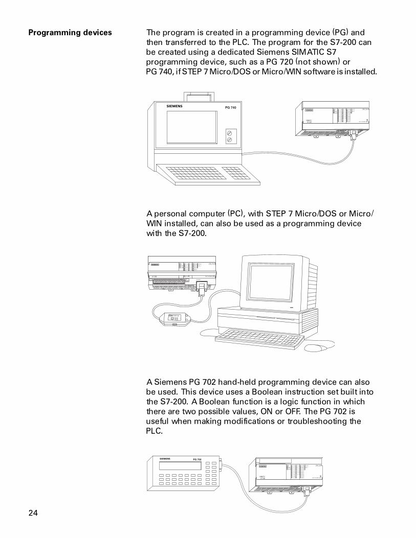
Programming devices The program is created in a programming device (PG) andthen transferred to the PLC. The program for the S7-200 canbe created using a dedicated Siemens SIMATIC S7programming device, such as a PG 720 (not shown) orPG 740, if STEP 7 Micro/DOS or Micro/WIN software is installed.
A personal computer (PC), with STEP 7 Micro/DOS or Micro/WIN installed, can also be used as a programming devicewith the S7-200.
A Siemens PG 702 hand-held programming device can alsobe used. This device uses a Boolean instruction set built intothe S7-200. A Boolean function is a logic function in whichthere are two possible values, ON or OFF. The PG 702 isuseful when making modifications or troubleshooting thePLC.
25
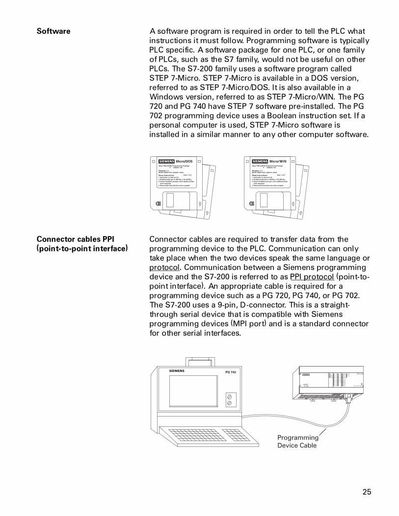
Software A software program is required in order to tell the PLC whatinstructions it must follow. Programming software is typicallyPLC specific. A software package for one PLC, or one familyof PLCs, such as the S7 family, would not be useful on otherPLCs. The S7-200 family uses a software program calledSTEP 7-Micro. STEP 7-Micro is available in a DOS version,referred to as STEP 7-Micro/DOS. It is also available in aWindows version, referred to as STEP 7-Micro/WIN. The PG720 and PG 740 have STEP 7 software pre-installed. The PG702 programming device uses a Boolean instruction set. If apersonal computer is used, STEP 7-Micro software isinstalled in a similar manner to any other computer software.
Connector cables PPI Connector cables are required to transfer data from the(point-to-point interface) programming device to the PLC. Communication can only
take place when the two devices speak the same language orprotocol. Communication between a Siemens programmingdevice and the S7-200 is referred to as PPI protocol (point-to-point interface). An appropriate cable is required for aprogramming device such as a PG 720, PG 740, or PG 702.The S7-200 uses a 9-pin, D-connector. This is a straight-through serial device that is compatible with Siemensprogramming devices (MPI port) and is a standard connectorfor other serial interfaces.
Programming
Device Cable
26
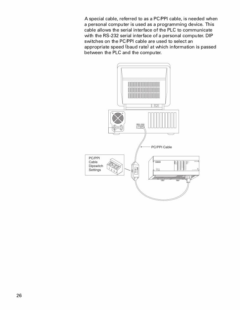
A special cable, referred to as a PC/PPI cable, is needed whena personal computer is used as a programming device. Thiscable allows the serial interface of the PLC to communicatewith the RS-232 serial interface of a personal computer. DIPswitches on the PC/PPI cable are used to select anappropriate speed (baud rate) at which information is passedbetween the PLC and the computer.
27
Review 21. A switch or a pushbutton is a ____________ input.
2. A lamp or a solenoid is an example of a ___________output.
3. The ____________ makes decisions and executescontrol instructions based on the input signals.
4. ____________ ____________ is a PLC programminglanguage that uses components resembling elementsused in a line diagram.
5. A ____________ consists of one or more instructionsthat accomplish a task.
6. Memory consists of an ____________ and____________ .
7. When talking about computer or PLC memory, 1Krefers to ____________ bits, bytes, or words.
8. Software that is placed in hardware is called____________ .
9. Which of the following is not required when creatingor changing a PLC program?
a. PLCb. Programming Devicec. Programming Softwared. Connector Cablee. Printer
10. A special cable, referred to as a ____________ cable, isneeded when a personal computer is used as aprogramming device.
28
S7-200 Micro PLCs
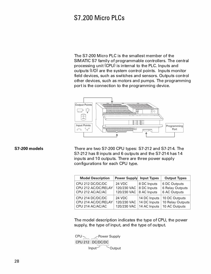
The S7-200 Micro PLC is the smallest member of theSIMATIC S7 family of programmable controllers. The centralprocessing unit (CPU) is internal to the PLC. Inputs andoutputs (I/O) are the system control points. Inputs monitorfield devices, such as switches and sensors. Outputs controlother devices, such as motors and pumps. The programmingport is the connection to the programming device.
Output Points
Input Points Programming
Port
S7-200 models There are two S7-200 CPU types: S7-212 and S7-214. TheS7-212 has 8 inputs and 6 outputs and the S7-214 has 14inputs and 10 outputs. There are three power supplyconfigurations for each CPU type.
The model description indicates the type of CPU, the powersupply, the type of input, and the type of output.
CPU 212 DC/DC/DC
CPU Power Supply
Input Output
29
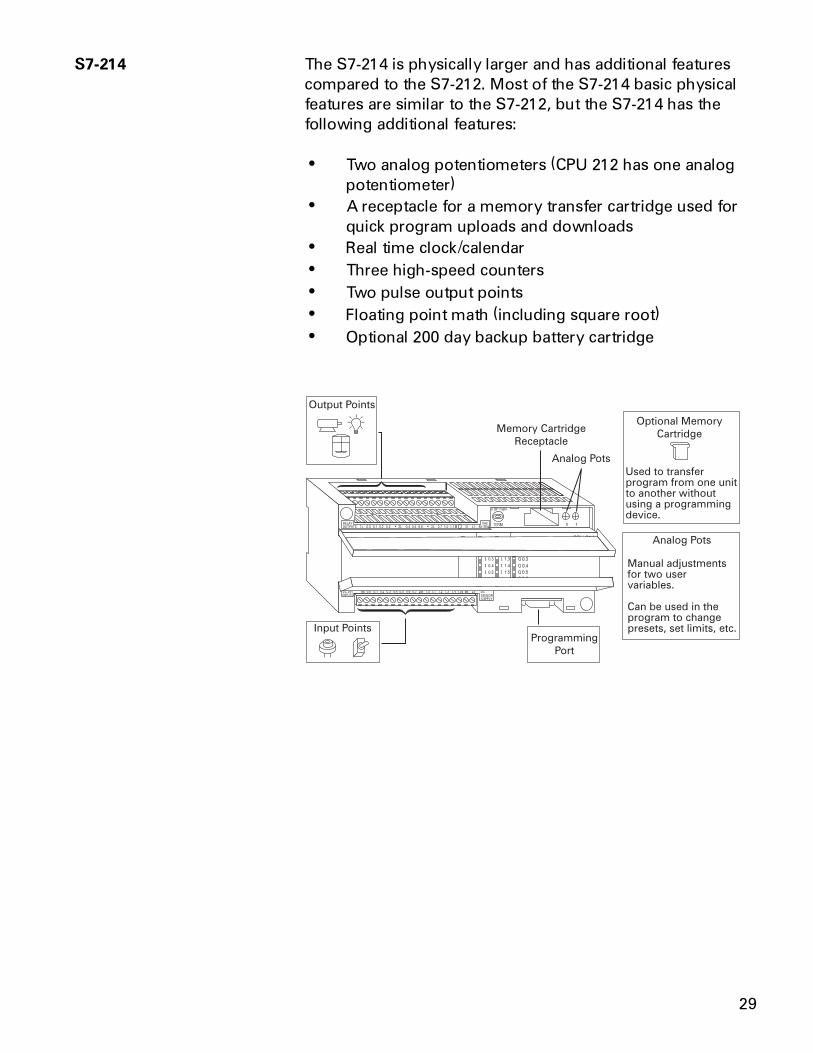
S7-214 The S7-214 is physically larger and has additional featurescompared to the S7-212. Most of the S7-214 basic physicalfeatures are similar to the S7-212, but the S7-214 has thefollowing additional features:
� Two analog potentiometers (CPU 212 has one analogpotentiometer)
� A receptacle for a memory transfer cartridge used forquick program uploads and downloads
� Real time clock/calendar� Three high-speed counters� Two pulse output points� Floating point math (including square root)� Optional 200 day backup battery cartridge
30
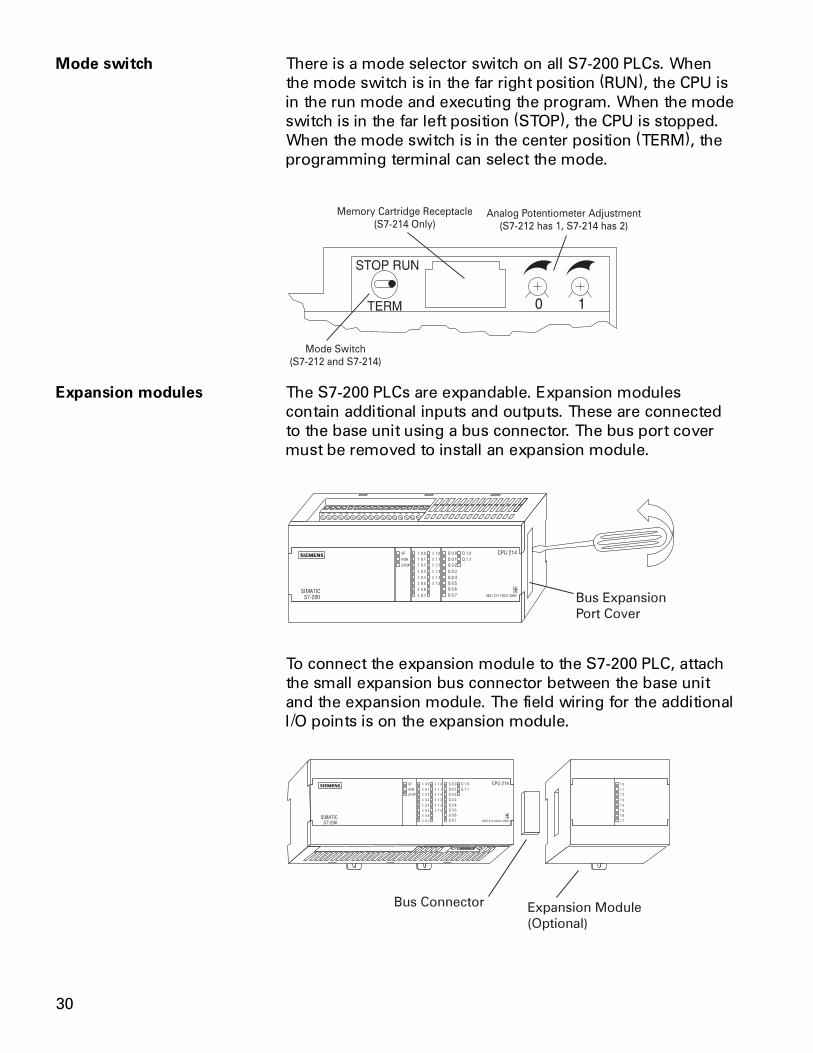
Mode switch There is a mode selector switch on all S7-200 PLCs. Whenthe mode switch is in the far right position (RUN), the CPU isin the run mode and executing the program. When the modeswitch is in the far left position (STOP), the CPU is stopped.When the mode switch is in the center position (TERM), theprogramming terminal can select the mode.
Expansion modules The S7-200 PLCs are expandable. Expansion modulescontain additional inputs and outputs. These are connectedto the base unit using a bus connector. The bus port covermust be removed to install an expansion module.
Bus Expansion
Port Cover
To connect the expansion module to the S7-200 PLC, attachthe small expansion bus connector between the base unitand the expansion module. The field wiring for the additionalI/O points is on the expansion module.
Bus Connector Expansion Module
(Optional)
31
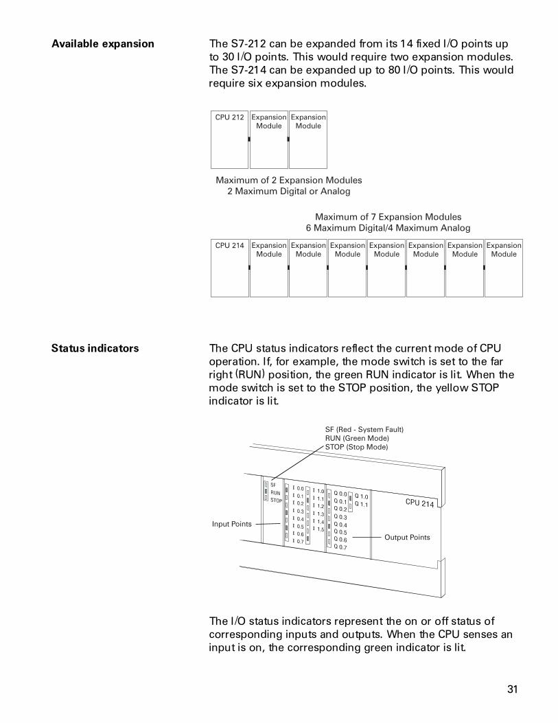
Available expansion The S7-212 can be expanded from its 14 fixed I/O points upto 30 I/O points. This would require two expansion modules.The S7-214 can be expanded up to 80 I/O points. This wouldrequire six expansion modules.
Status indicators The CPU status indicators reflect the current mode of CPUoperation. If, for example, the mode switch is set to the farright (RUN) position, the green RUN indicator is lit. When themode switch is set to the STOP position, the yellow STOPindicator is lit.
The I/O status indicators represent the on or off status ofcorresponding inputs and outputs. When the CPU senses aninput is on, the corresponding green indicator is lit.
32
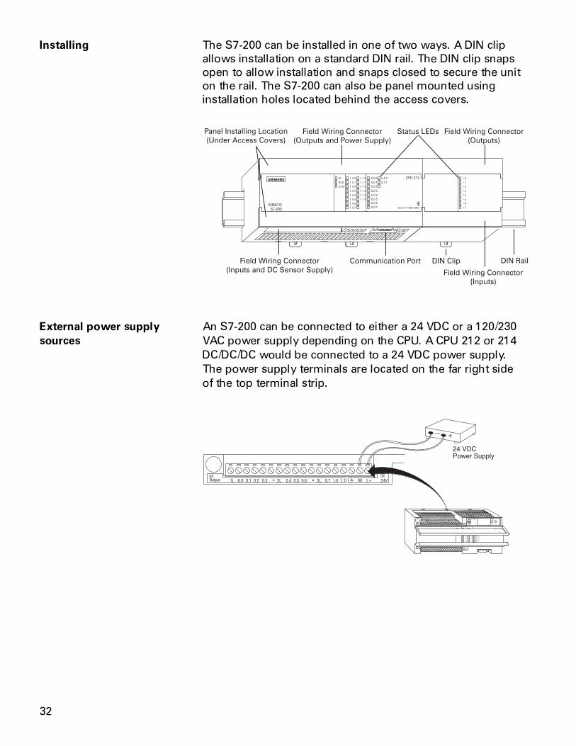
Installing The S7-200 can be installed in one of two ways. A DIN clipallows installation on a standard DIN rail. The DIN clip snapsopen to allow installation and snaps closed to secure the uniton the rail. The S7-200 can also be panel mounted usinginstallation holes located behind the access covers.
External power supply An S7-200 can be connected to either a 24 VDC or a 120/230sources VAC power supply depending on the CPU. A CPU 212 or 214
DC/DC/DC would be connected to a 24 VDC power supply.The power supply terminals are located on the far right sideof the top terminal strip.
MOutput
33
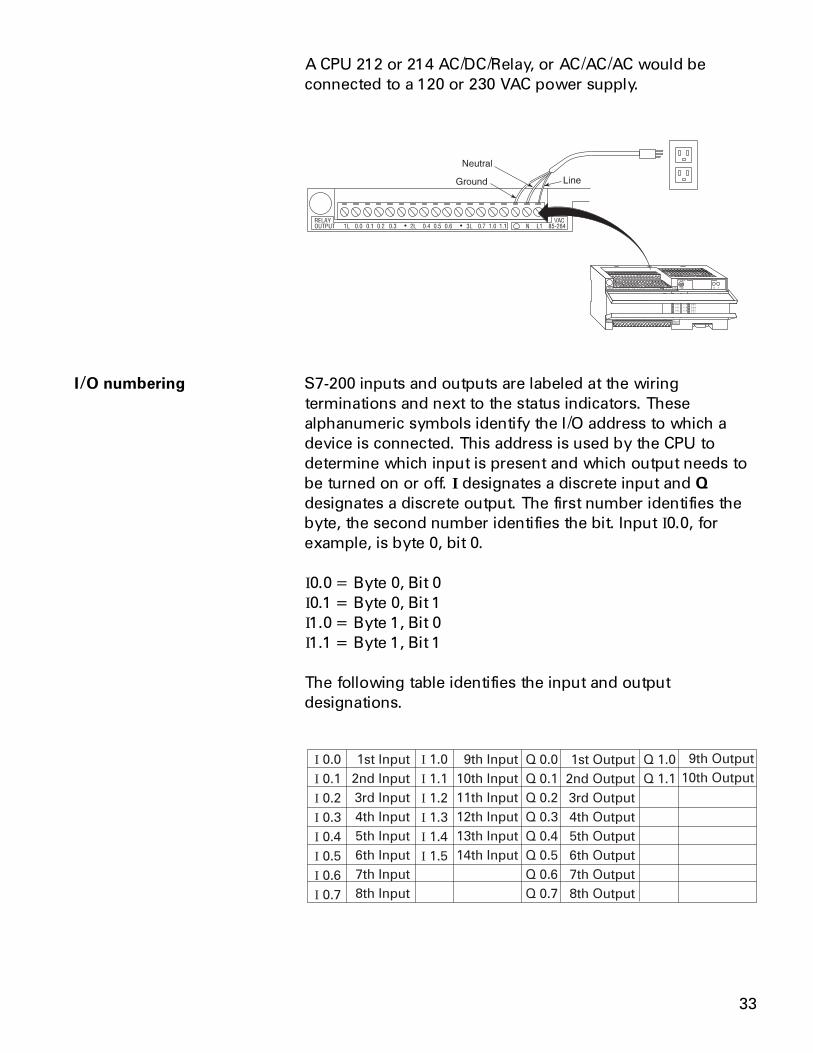
A CPU 212 or 214 AC/DC/Relay, or AC/AC/AC would beconnected to a 120 or 230 VAC power supply.
I/O numbering S7-200 inputs and outputs are labeled at the wiringterminations and next to the status indicators. Thesealphanumeric symbols identify the I/O address to which adevice is connected. This address is used by the CPU todetermine which input is present and which output needs tobe turned on or off. I designates a discrete input and Qdesignates a discrete output. The first number identifies thebyte, the second number identifies the bit. Input I0.0, forexample, is byte 0, bit 0.
I0.0 = Byte 0, Bit 0I0.1 = Byte 0, Bit 1I1.0 = Byte 1, Bit 0I1.1 = Byte 1, Bit 1
The following table identifies the input and outputdesignations.
I
I
I
I
I
I
I
I
0.0
0.1
0.2
0.3
0.4
0.5
0.6
0.7
I
I
I
I
I
I
1.0
1.1
1.2
1.3
1.4
1.5
Q 0.0
Q 0.1
Q 0.2
Q 0.3
Q 0.4
Q 0.5
Q 0.6
Q 0.7
Q 1.0
Q 1.1
1st Input
2nd Input
3rd Input
4th Input
5th Input
6th Input
7th Input
8th Input
1st Output
2nd Output
3rd Output
4th Output
5th Output
6th Output
7th Output
8th Output
9th Input
10th Input
11th Input
12th Input
13th Input
14th Input
9th Output
10th Output
34
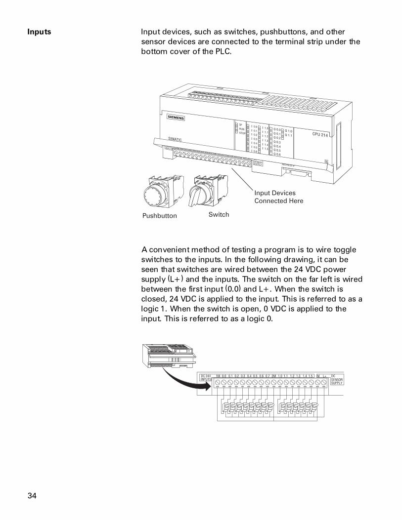
Inputs Input devices, such as switches, pushbuttons, and othersensor devices are connected to the terminal strip under thebottom cover of the PLC.
Input Devices
Connected Here
Pushbutton Switch
A convenient method of testing a program is to wire toggleswitches to the inputs. In the following drawing, it can beseen that switches are wired between the 24 VDC powersupply (L+) and the inputs. The switch on the far left is wiredbetween the first input (0.0) and L+. When the switch isclosed, 24 VDC is applied to the input. This is referred to as alogic 1. When the switch is open, 0 VDC is applied to theinput. This is referred to as a logic 0.
35
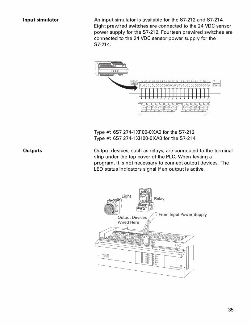
Input simulator An input simulator is available for the S7-212 and S7-214.Eight prewired switches are connected to the 24 VDC sensorpower supply for the S7-212. Fourteen prewired switches areconnected to the 24 VDC sensor power supply for theS7-214.
Type #: 6S7 274-1XF00-0XA0 for the S7-212Type #: 6S7 274-1XH00-0XA0 for the S7-214
Outputs Output devices, such as relays, are connected to the terminalstrip under the top cover of the PLC. When testing aprogram, it is not necessary to connect output devices. TheLED status indicators signal if an output is active.
From Input Power SupplyOutput Devices
Wired Here
RelayLight
36
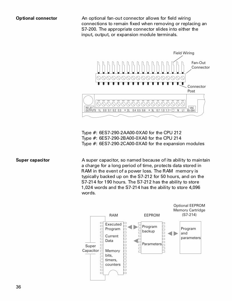
Optional connector An optional fan-out connector allows for field wiringconnections to remain fixed when removing or replacing anS7-200. The appropriate connector slides into either theinput, output, or expansion module terminals.
Field Wiring
Fan-Out
Connector
Connector
Post
Type #: 6ES7-290-2AA00-0XA0 for the CPU 212Type #: 6ES7-290-2BA00-0XA0 for the CPU 214Type #: 6ES7-290-2CA00-0XA0 for the expansion modules
Super capacitor A super capacitor, so named because of its ability to maintaina charge for a long period of time, protects data stored inRAM in the event of a power loss. The RAM memory istypically backed up on the S7-212 for 50 hours, and on theS7-214 for 190 hours. The S7-212 has the ability to store1,024 words and the S7-214 has the ability to store 4,096words.
37
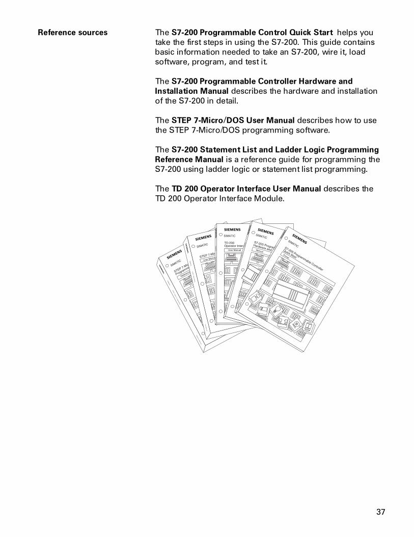
Reference sources The S7-200 Programmable Control Quick Start helps youtake the first steps in using the S7-200. This guide containsbasic information needed to take an S7-200, wire it, loadsoftware, program, and test it.
The S7-200 Programmable Controller Hardware andInstallation Manual describes the hardware and installationof the S7-200 in detail.
The STEP 7-Micro/DOS User Manual describes how to usethe STEP 7-Micro/DOS programming software.
The S7-200 Statement List and Ladder Logic ProgrammingReference Manual is a reference guide for programming theS7-200 using ladder logic or statement list programming.
The TD 200 Operator Interface User Manual describes theTD 200 Operator Interface Module.
38
Review 31. The two models of S7-200 are ____________ and
____________ .
2. Which of the following is not available on an S7-212?
a. Mode Switchb. Memory Cartridge Receptaclec. Programming Portd. Status Indicators
3. An S7-212 can have a maximum of ____________expansion modules and an S7-214 can have a maxi-mum of ____________ expansion modules.
4. A CPU 212 DC/DC/DC has ____________ DC inputsand ____________ DC outputs.
5. A CPU 214 AC/AC/AC has ____________ AC inputsand ____________ AC outputs.
6. The S7-214 has an optional ____________ cartridgethat can quickly transfer a program from one PLC toanother.
7. The fourth output of an S7-200 would be labeled____________ .
8. S7-200 can be panel mounted or installed on a____________ rail.
9. A super capacitor will maintained data stored in RAMfor up ____________ hours on an S7-212 and up to____________ hours on an S7-214.