Embed Size (px)
Citation preview

Operators Manual Multi-parameter patient monitor LifeWindow 6000 Rev 5 Apr 10 1
Table of Contents Section 1 - Introduction A. About this Manual ..................................................................2 B. Manufacture's Responsibility ............................................2 C. Warranty ...........................................................................2 D. General Safety .....................................................................2 E. Unpacking and Accessories .................................................3
Section 2 – Quick Start A. Description ...........................................................................4 B. Turning-On ...........................................................................8 C. Alarm and Pulse Sound.........................................................8 D. Patient Management..............................................................8 E. Date and Time........................................................................9 F. Monitoring Screen...................................................................9 G. Traces Setting........................................................................9 H. Patient Type...........................................................................9 I. ECG Monitoring ....................................................................10 J. Impedance Respiration Monitoring....10 K. SpO2 Monitoring....................................................................10 L. CO2 Monitoring......................................................................10 M. NIBP Monitoring....................................................................11 N. Temperature Monitoring........................................................11 O. Invasive Pressure Monitoring................................................12 P. FIO2 Monitoring..............................................................12 Q. Trends. .........................................................................13 R. Discharge Patient and Save Data..13 S. Battery Operation ...........................13 T. Turning-OFF.............................13
Section 3 – Print, Reports and Networking A.. Printing and Reports....14 B. Networking...........................20
Section 4 - ECG Monitoring A. Introduction...............23 B. Safety Considerations............................................................23 C. Patient Connections...............................................................23 D. ECG Monitoring......................................................................25 E. ECG Menu...................................................................26 F. ECG Scale...................................................................26 G. 5 Lead Mode.......................................................................27 H. 3 Lead Mode....................................................................27 I. ECG Filter..27 J. Heart Rate Limits.28 K. Pace Maker..28 L. ECG Sweep Speed.....28 M. ECG Pulse Test..28 N. ECG Patient Type...28 O. ECG Interpretation.28 P. ECG ST Segment...29 Q. ECG Arrhythmia Detection.......31 R. ECG Alarm Messages32
Section 5 – Bioimpedance Respiration A. Overview..33 B. Patient Connections...33 C. Respiration Menu...34 D. Respiration Size.35 E. Respiration Rate Alarm Limits..35 F. Respiration Apnea Alarm Delay..............................................35 G. Respiration Coincidence..35 H. Respiration ON/OFF..35 I. Respiration Alarm Messages.35
Section 6 – Pulse Oximetry Monitoring A. Patient connections ....................................................36 B. SpO2 monitoring ........................................................37 C. SpO2 Waveform and Bar-graph...................................38 D. SpO2 Alarm Limits ......................................................39 E. SpO2 Alarm Messages ...............................................39
Section 7 - CO2 Mainstream Monitoring A. Overview..........................................39
Section 7.1 - CO2 Mainstream Monitoring A. Principle of Operation .....................40 B. Indications for Use...................................40 C. Patient Connections..................41 D. Monitoring CO2 ....................44
Section 7.2 - CO2 Sidestream Monitoring A. Principle of Operation ................................45 B. Indications for Use ..............................................45 C. Patient Connections ......................46 D. Monitoring CO2...................51
Section 8- NIBP Monitoring A. Cuff Selection and Placement................53 B. NIBP Monitoring.............................................................55 C. NIBP Alarm Messages....56
Section 9- Temperature Monitoring A. Patient Connections........................................................57 B. Temperature Monitoring..................................................57
Section 10- Invasive Pressure Monitoring A. Pressure Transducer......................................................58 B. Transducer Connection....................................................59 C. IP Scale and Label....................................................60 D. Trigger Source...................................................61 E. Pulsatile / Static Mode...........................................61 F. Transducer Zero................................................61 G. IP Alarm Limits..................................................62 H. IP Alarm Messages...........................................62
Section 11 – Fraction of Inspired Oxygen A. Principle of Operation .....................................................62 B. Patients Connections ......................................................63 C. Calibration.........................................................................64 D. FIO2 Monitoring.. .............................................................65
Section 12 - Technical Specification A. Mechanical Description ...................................................67 B. Power Requirements .......................................................67 C. ECG ................................................................................67 D. SpO2 Pulse Oximeter .......................................................67 E. Non-Invasive Blood Pressure............................................67 F. Temperature.................................................68 G. CO2...................................................68 H. Invasive Pressure..........................................69 I. FIO2.....................................................69 J. Bioimpedance Respiration....70 K. Display ..............................70 L. Environment Specifications ................................................70 M. Trends ...............................................................................70 N. Auxiliary Output (Rear Panel) ..............................................70
Section 13- Maintenance A. The Monitor ........................................................................71 B. Probes ................................................................................71 C. Patient Cables .....................................................................72 D. Battery ................................................................................72
Warranty Terms & Conditions ........................................73

Digicare Biomedical Technology
Operators Manual Multi-parameter patient monitor LifeWindow LW6000 Rev 5 Apr 10 2
SECTION 1 – INTRODUCTION
A. ABOUT THIS MANUAL This operator’s manual has been prepared to provide information on the correct use of the
LifeWindow 6000 multi-parameter patient monitor. It contains performance specifications, installation, operation and maintenance information. It is intended for trained health-care professionals.
B. MANUFACTURER’S RESPONSIBILITY
• The manufacturer of this equipment is responsible for the effects on safety, reliability, and performance of the equipment only if: • The equipment is used in accordance with the instructions in this manual. • The electrical installation complies with all applicable regulations. • Assembly operations, extensions, re-adjustments, or repairs are carried out by person’s authorized by the manufacturer.
Incorrect operation or failure of the user to maintain the monitor in accordance with proper maintenance procedures relieves the manufacturer or his agent from all consequent non-compliance, damage or injury.
• It is up to the user to ensure that any applicable regulations respecting the installation and operation of the monitor be observed.
C. WARRANTY
All products manufactured by Digicare Biomedical Technology Inc. are warranted to be free from defects in material and workmanship and to operate within published specifications, under normal use, for a period of one year from date of original shipment. The warranty on accessories is ninety (90) days. If an examination by Digicare, discloses such products or component parts to be defective, then our obligation is limited to repair or replacement (at our option).
D. GENERAL SAFETY
1 - INDICATIONS
The LifeWindow 6000 series is a Class 1 device designed for continuous operation in accordance with the Safety Standard EN60601-1. The Class 1 device MUST BE connected to the external protective conductor to be operated with the external MAINS LINE. It is intended for use by person’s trained in professional health care, in the hospital / clinic environment. The operator must be thoroughly familiar with the instructions in this manual before using the instrument. The unit is configured to measure and monitor the following available parameters:
• ECG Waveform 3 leads, (5 leads optional);
• Heart Rate (HR) from ECG ;
• ECG arrhythmia and ST segment analysis;
• Blood oxygen saturation (SpO2 or pulse oximetry);

Digicare Biomedical Technology
Operators Manual Multi-parameter patient monitor LifeWindow LW6000 Rev 5 Apr 10 3
• SpO2 waveform (Plethysmogram);
• Two Temperature channels;
• Four Invasive Pressure channels;
• Pulse ( from SpO2 ,NIBP, IP1, IP2, IP3 or IP4) rate;
• NIBP Systolic, Diastolic and mean arterial pressure;
• End-tidal CO2 concentration (EtCO2) – Mainstream or Sidestream;
• Inspired CO2 concentration (inCO2) – Mainstream or Sidestream;
• Respiration rate (from EtCO2 waveform);
• Inspired Fraction of O2 ( FIO2 );
• Inspired Anesthetic Agent (isofluran, sevofluran, halothan, desfluran and enfluran);
• End-tidal Anesthetic Agent (isofluran, sevofluran, halothan, desfluran and enfluran);
• Inspired N2O concentration;
• End-tidal N2O concentration;
• Cardiac Output / Right Ventricular Ejection Fraction by thermodilution; Derived hemodynamic parameters; CONFIGURATION CODE Electrocardiogram – 3 Lead ECG........................................................................................ E Electrocardiogram – 3 and 5 Lead ECG.............................................................................5E Pulse Oximeter and Plethysmogram ................................................................................. S FIO2 – Inspired Fraction of Oxygen ................................................................................... F CO2 DualCap – Mainstream and Sidestream Capnography .............................................. D CO2 - Mainstream Capnography ....................................................................................... M CO2 - Sidestream Capnography ........................................................................................ C CO2 – Sidestream with Anaesthetic Agents ...G Non-invasive Blood Pressure - NIBP .................................................................................. N Invasive Pressure ( up to 4 two channels) ......................................................................... #P Temperature (up to 2 channels) ......................................................................................... #T Cardiac Output / REF............................................................................................................O 2 - CAUTIONS The LifeWindow™ 6000 was designed and tested accordingly to the ELECTRO-MAGNETIC COMPATIBILITY Standard IEC601-1-2. However, the operator is responsible to verify if the monitor is been affected or affecting others electrical equipment. Equipments like electrocautery and image scanners can generate interference and cause degradation of the LifeWindow™ 6000 performance. To avoid this situation, it should be installed as far as possible of those equipment. 3- CONTRAINDICATIONS The LifeWindow™ 6000 series is NOT intended to be used during MRI (magnetic resonance imaging). The LifeWindow™ 6000 is NOT suitable for use in the presence of a flammable anaesthetic mixture with air or with oxygen or nitrous oxide.
E. UNPACKING AND ACCESSORIES
Carefully remove the monitor and its accessories form the shipping carton. Save the packing
materials in case the monitor must be shipped or stored. Ensure your LifeWindow 6000 has the items listed in the SHIPPING LIST inside the carton.
Digicare Biomedical Technology
Operators Manual Multi-parameter patient monitor " LifeWindow LW6000 Rev 5 Apr 10 " 4
SECTION 2 – QUICK START
A. DESCRIPTION
1 – FRONT PANEL
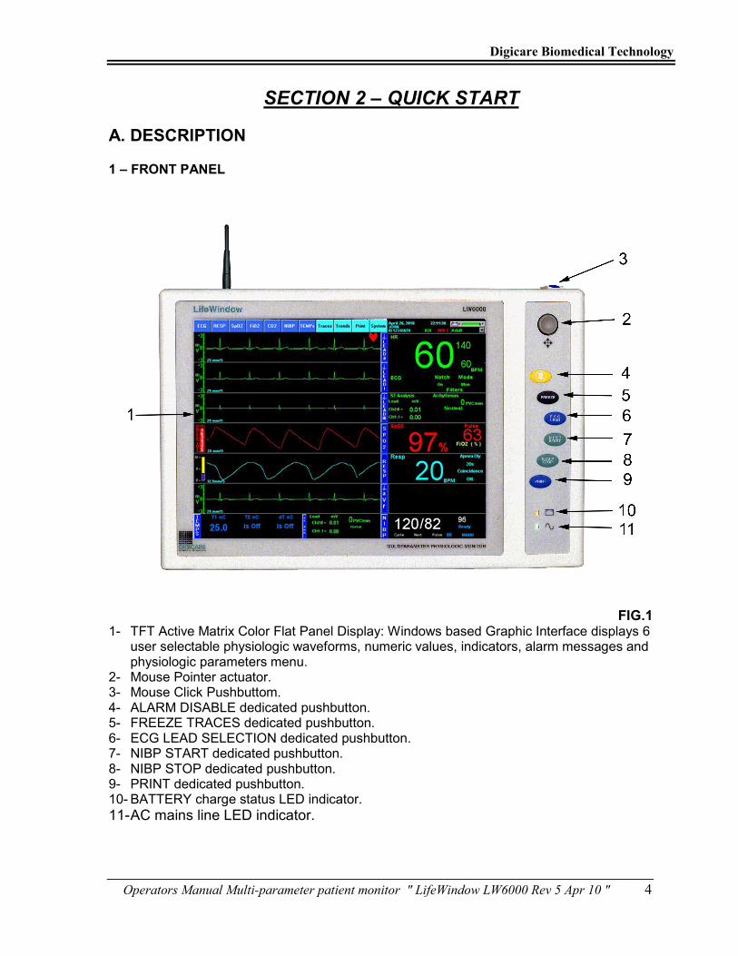
FIG.1 1- TFT Active Matrix Color Flat Panel Display: Windows based Graphic Interface displays 6
user selectable physiologic waveforms, numeric values, indicators, alarm messages and physiologic parameters menu.
2- Mouse Pointer actuator. 3- Mouse Click Pushbuttom. 4- ALARM DISABLE dedicated pushbutton. 5- FREEZE TRACES dedicated pushbutton. 6- ECG LEAD SELECTION dedicated pushbutton. 7- NIBP START dedicated pushbutton. 8- NIBP STOP dedicated pushbutton. 9- PRINT dedicated pushbutton. 10- BATTERY charge status LED indicator.
11- AC mains line LED indicator.

Digicare Biomedical Technology
Operators Manual Multi-parameter patient monitor " LifeWindow LW6000 Rev 5 Apr 10 " 5
2 – PATIENT CONNECTIONS PANEL
FIG. 2
12- NIBP hose receptacle. Accept cuff to Non Invasive Blood Pressure and Pulse determination and monitoring.
13- CO2 connector for external Plug & Play Sidestream or Mainstream CO2 and Respiration Rate determination and monitoring.
14- Cardiac Output Connector. Accepts Cardiac Output bifurcated cable for determination of Cardiac Output and Right Ventricle Ejection Fraction (REF) (Optional).
15- Temperature Channel 1 connector. Accepts temperature cable and sensor for non-invasive Temperature determination and monitoring.
16- Temperature Channel 2 connector. Accepts temperature cable and sensor for non-invasive Temperature determination and monitoring.
17- FIO2 connector. Accept cable and sensor to Inspired Fraction of Oxygen determination and monitoring, using an air way adaptor.
18- SpO2 connector. Accepts pulse oximetry patient sensor cable to non-invasive determination and monitoring of the blood oxygen content.
19- Invasive Pressure Channel 1 connector. Accepts pressure transducer cable to invasive determination and monitoring of blood pressure.
20- Invasive Pressure Channel 2 connector. Accepts pressure transducer cable to invasive determination and monitoring of blood pressure.
21- Invasive Pressure Channel 3 connector. Accepts pressure transducer cable to invasive determination and monitoring of blood pressure.

Digicare Biomedical Technology
Operators Manual Multi-parameter patient monitor " LifeWindow LW6000 Rev 5 Apr 10 " 6
22- Invasive Pressure Channel 4 connector. Accepts pressure transducer cable to invasive determination and monitoring of blood pressure.
23- ECG connector. Accepts ECG cable for electrocardiogram and Heart Rate monitoring.
3 – REAR PANEL
FIG.3 24- Mains Line IEC connector. Accepts power cable from mains line. Have 1 main fuse and 1
spare fuse inside. 25- General Power switch. Interrupt power from internal battery and mains power supply. 26- On / Standby switch. Momentary contact switch to turn-on and off the unit. To turn-on the
unit, double click this switch. 27- USB 1 connector for external printer, keyboard and USB storage devices. 28- Ethernet Connector. Connection to Ethernet network standard. 29- Keyboard Connector. PS2 connection to a standard AT type keyboard used only to service
purposes. 30- Video Connector. Connection to a standard CRT video. 31- Auxiliary Connector. Supply analog output signals, trigger signals and one RS232
communication port. 32- Antenna for wireless networking. 33- Internal CO2 Sidestream Vent port for connection to scavenger systems or keep open.

Digicare Biomedical Technology
Operators Manual Multi-parameter patient monitor " LifeWindow LW6000 Rev 5 Apr 10 " 7
4 – MONITORING SCREEN
FIG.4
29 – First waveform user selected area, showing ECG Lead II waveform in Thin Line Style, scale (-1 to +1mV), sweep speed of 25mm/s and QRS detected INDICATOR (HEART). 30 – Second waveform user selected area, showing ECG Lead I waveform in Thin Line Style, scale (-1 to +1mV) and sweep speed of 25mm/s. 31 – Third waveform user selected area, showing ECG Lead III waveform in Thin Line Style, scale (-1 to +1mV) and sweep speed of 25mm/s. 32 – Forth waveform user selected area, showing SpO2 waveform in Thin Line Style, with Pulse Level strength scale (1 to 8), sweep speed of 25mm/s. 33 – Fifth waveform user selected area, showing Impedance Respiration waveform in Thin Line Style, with Resp Size Scale, sweep speed of 12.5mm/s. 34 – Sixth waveform user selected area, showing ECG Lead aVf waveform in Thin Line Style, scale (-1 to +1mV) and sweep speed of 25mm/s. 35 – ECG menu selection. 36 – RESP menu selection (optional). 37 – SpO2 menu selection. 38 – FIO2 menu selection. 39 – CO2 menu selection. 40 – NIBP menu selection. 41 – Temperature menu selection. 42 – Traces configuration menu selection.
Digicare Biomedical Technology
Operators Manual Multi-parameter patient monitor " LifeWindow LW6000 Rev 5 Apr 10 " 8
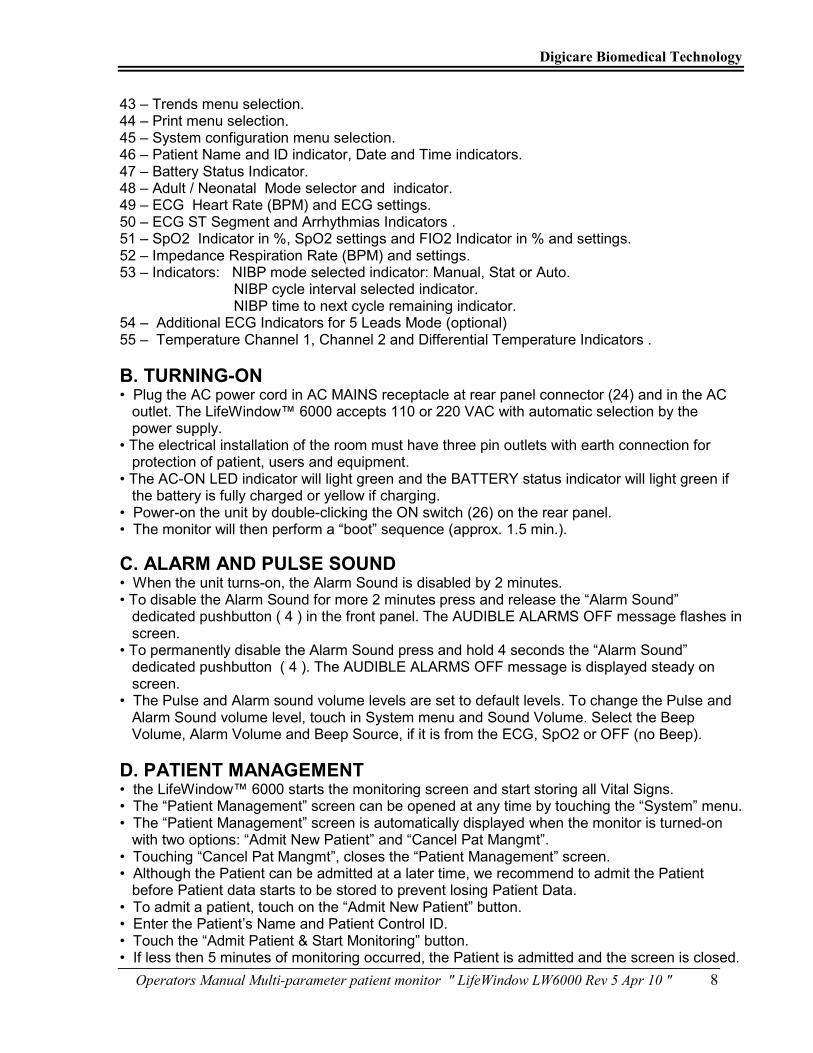
43 – Trends menu selection. 44 – Print menu selection. 45 – System configuration menu selection. 46 – Patient Name and ID indicator, Date and Time indicators. 47 – Battery Status Indicator. 48 – Adult / Neonatal Mode selector and indicator. 49 – ECG Heart Rate (BPM) and ECG settings. 50 – ECG ST Segment and Arrhythmias Indicators . 51 – SpO2 Indicator in %, SpO2 settings and FIO2 Indicator in % and settings. 52 – Impedance Respiration Rate (BPM) and settings. 53 – Indicators: NIBP mode selected indicator: Manual, Stat or Auto. NIBP cycle interval selected indicator. NIBP time to next cycle remaining indicator. 54 – Additional ECG Indicators for 5 Leads Mode (optional) 55 – Temperature Channel 1, Channel 2 and Differential Temperature Indicators .
B. TURNING-ON
• Plug the AC power cord in AC MAINS receptacle at rear panel connector (24) and in the AC outlet. The LifeWindow™ 6000 accepts 110 or 220 VAC with automatic selection by the power supply. • The electrical installation of the room must have three pin outlets with earth connection for protection of patient, users and equipment. • The AC-ON LED indicator will light green and the BATTERY status indicator will light green if the battery is fully charged or yellow if charging. • Power-on the unit by double-clicking the ON switch (26) on the rear panel. • The monitor will then perform a “boot” sequence (approx. 1.5 min.).
C. ALARM AND PULSE SOUND
• When the unit turns-on, the Alarm Sound is disabled by 2 minutes. • To disable the Alarm Sound for more 2 minutes press and release the “Alarm Sound” dedicated pushbutton ( 4 ) in the front panel. The AUDIBLE ALARMS OFF message flashes in screen. • To permanently disable the Alarm Sound press and hold 4 seconds the “Alarm Sound” dedicated pushbutton ( 4 ). The AUDIBLE ALARMS OFF message is displayed steady on screen. • The Pulse and Alarm sound volume levels are set to default levels. To change the Pulse and Alarm Sound volume level, touch in System menu and Sound Volume. Select the Beep Volume, Alarm Volume and Beep Source, if it is from the ECG, SpO2 or OFF (no Beep).
D. PATIENT MANAGEMENT
• the LifeWindow™ 6000 starts the monitoring screen and start storing all Vital Signs. • The “Patient Management” screen can be opened at any time by touching the “System” menu. • The “Patient Management” screen is automatically displayed when the monitor is turned-on with two options: “Admit New Patient” and “Cancel Pat Mangmt”. • Touching “Cancel Pat Mangmt”, closes the “Patient Management” screen. • Although the Patient can be admitted at a later time, we recommend to admit the Patient before Patient data starts to be stored to prevent losing Patient Data. • To admit a patient, touch on the “Admit New Patient” button. • Enter the Patient’s Name and Patient Control ID. • Touch the “Admit Patient & Start Monitoring” button. • If less then 5 minutes of monitoring occurred, the Patient is admitted and the screen is closed.

Digicare Biomedical Technology
Operators Manual Multi-parameter patient monitor " LifeWindow LW6000 Rev 5 Apr 10 " 9
• If more then 5 minutes of data is available, you need to choose what to do with the with the patient’s data in the buffer, with three options: • “Keep for the new patient”. Touch to include data to new patient. • “Save as different patient”. Touch to save data to different patient. • “Discard Data”. Touch to discard.
E. DATE AND TIME
• Check if the current “Date and Time” displayed in the Indicator (47) are correct. • To change the Date and Time, touch the “SYSTEM” menu and touch “Date/Time Settings”. • Set current location “Date and Time”. Touch OK to finish.
F. MONITORING SCREEN • The LifeWindow™ 6000 monitoring screen is pre-configured accordingly to the Vital Signs parameters that are installed and turned-on. The traces are pre-configured to keep “In-line Logic” with the Indicators area in the right of the traces area. • To turn-off any Vital Sign that is not going to be used in patient’s monitoring, touch the Vital Sign menu and touch ECG OFF or SPO2 OFF, etc. The monitoring screen may change some Traces settings and Indicators. • Factory Default Settings are configured to standard applications. As the user changes Alarm Limits and other settings, the LifeWindow™ 6000 will save the changes when turned-off. Next time the unit is turned-on, the last saved settings will remain. • To return the unit to the Factory Defaults, touch in the “System” menu and touch in “Load Factory Default Settings”.
G. TRACES SETTING
• The LifeWindow™ 6000 six traces are configured and cascaded accordingly to the Vital Signs parameters installed and turned-on. • You can select any physiological waveform from one to six of the available traces. You can also cascade the traces up to 3 individual loops. • Move the Pointer to TRACES icon and press the Select pushbutton. • Select TRACE waveform source (ECG, SpO2 Plethysmogram, Capnogram, or No Selection). • Select TRACE sweep speed (6.25mm/s, 12.5mm/s, 25mm/s, 50mm/s or 100mm/s). • Select TRACE color. • Select TRACE style (Thin line or Fill In). • Press the Cascade Traces button if you want to cascade two or more traces. • You can create up to 3 cascade loops: Loop 1, Loop 2 and Loop 3. Select the Loop waveform Source. Select the Sweep Speed, Color and Style for each trace. • Press the Done button to finish. • Note: When the LifeWindow™ 6000 is turned-off and turned back on, the traces will return to the original pre-configuration accordingly to the physiological parameters that are installed and turned-on, to keep “In-line Logic” with the Indicators area in the right of the traces area.
H. PATIENT TYPE
• Patient Type has two modes: Adult and Neonatal. It affects the ECG and NIBP functions only. All other Vital Signs functions are not affected by the Patient Type selected. • Selection of Patient Type shall be based on the Patient’s Heart Rate range for ECG monitoring and Cuff size to be used for NIBP monitoring. Adult Patient Type : ECG Heart Rate Range: 5 to 220 BPM NIBP Cuff Size #: 5, 7, 8, 9, 10 and 11

Digicare Biomedical Technology
Operators Manual Multi-parameter patient monitor " LifeWindow LW6000 Rev 5 Apr 10 " 10
Neonatal Patient Type : ECG Heart Rate Range: 30 to 300 BPM NIBP Cuff Size #: 1, 2, 3, 4 and 6
I. ECG MONITORING • The ECG function is pre-configured with the following default settings. To change the ECG settings touch the ECG menu and change the desired setting. Heart Rate High Limit : 140 BPM Heart Rate Low Limit : 60 BPM Heart Rate Averaging : 8 Beats for Adult, 16 Beats for Neonatal. ECG Scale : - 0.5 mV to +1.0 mV ECG Filter Mains Notch : ON ECG Filter Digital : ON ECG Lead Selection : II • Prepare the electrode sites in the standard configuration for RA (Right Arm), LA (Left Arm) and LL (Left Leg). Application sites should be clean and dry. Shave or clip excess hair if necessary. Use conductive ECG gel if necessary. • Connect the 3 Leadwires to the ECG cable. Connect the ECG cable to the receptacle (13) in the patient panel. Install the 3 electrodes in the patient. More details in Section 4.
• A visual indicator (♥) and a beep Sound indicates R wave detection and the ECG waveform and Heart Rate reading are displayed.
J. IMPEDANCE RESPIRATION MONITORING • The Impedance Respiration function is pre-configured with the following default settings. To change the Resp settings touch the Resp menu and change the desired setting. Resp. Rate RPM High Limit : OFF Resp. Rate RPM Low Limit : 5 RPM Apnea Alarm Delay : 20 seconds Respiration Size : 3 Coincidence Alarm : ON • Make sure to use high quality ECG electrodes with Low Resistance. • The quality of ECG electrodes directly affect the Impedance Respiration detection. • The Respiration Size adjust the Respiration waveform size but do not change the Impedance Respiration sensitivity and Respiration Rate count.
K. SpO2 MONITORING • The SpO2 function is pre-configured with the following default settings. To change the SpO2 settings touch the SpO2 menu and change the desired setting. SpO2 % High Limit : OFF SpO2 % Low Limit : 88% SpO2 Pulse High Limit : 140 BPM SpO2 Pulse Low Limit : 60 BPM • Choose the SpO2 sensor type and prepare the SpO2 sensor and clip. • Connect the sensor assembly to the SpO2 Patient Cable: • Plug the SpO2 Patient Cable into the SpO2 connector (18) on the side panel of the monitor. Push the cable in until you hear an audible “click”. • The yellow SpO2 SENSOR message changes for the green Searching SpO2 message, the Bar-graph shows the SpO2 Pulse Level, the SpO2 waveform, SpO2 % and Pulse Rate values are displayed.
L. CO2 MONITORING
• The LifeWindow LW 6000 automatically starts the CO2 function when CO2 sensor is

Digicare Biomedical Technology
Operators Manual Multi-parameter patient monitor " LifeWindow LW6000 Rev 5 Apr 10 " 11
connected to the unit. • The CO2 function is pre-configured with the following default settings. To change the CO2 settings touch the CO2 menu and change the desired setting. CO2 Waveform Scale : 0 to 50 mmHg EtCO2 High Limit : 45 mmHg EtCO2 Low Limit : 20 mmHg InsCO2 High Limit : 10 mmHg InsCO2 Low Limit : OFF Resp Rate High Limit : 50 BPM Resp Rate Low Limit : 5 BPM
• Select the appropriate airway adapter for mainstream or sample line with adapter for sidestream based on the patient and monitoring situation. • Connect the sample line with adapter to receptacle (10) in the Patient Panel, or; • Connect the sample line with adapter to the External Sidestream module and connect the module to connector (17) in the Patient Panel, or; • Connect the Mainstream sensor assembled in the airway adapter to connector (17). • Wait for the “Sensor Warm Up” message to clear. If the “Zero Required” message is displayed, proceed with a Zero Calibration Procedure as explained in Sections 6.1 and 6.2. • Connect the airway adapter to the patient’s air way assembled circuit.
M. NIBP MONITORING
• The NIBP function is pre-configured with the following default settings. To change the NIBP settings touch the NIBP menu and change the desired setting. NIBP Cycle Mode : Manual NIBP Systolic Upper Limit : 160 mmHg NIBP Systolic Lower Limit : 100 mmHg NIBP Diastolic Upper Limit : 100 mmHg NIBP Diastolic Lower Limit : 60 mmHg NIBP Mean Upper Limit : 120 mmHg NIBP Mean Lower Limit : 80 mmHg NIBP Pulse Upper Limit : 140 BPM NIBP Pulse Lower Limit : 60 BPM • The widest cuff that can be placed on the patient, without extending beyond the joint, should be selected. Cuff width should be 40 – 60% of limb circumference. Wrap for a snug fit. • The monitor comes standard with six different sizes of cuffs. They are marked to aid in proper cuff selection. When a cuff is wrapped around a site, its index edge should be in the range indicated on the cuff. The cuff is too small or too large if the index edge is outside the range. • On the NIBP menu, select the NIBP mode (Manual, Auto or Stat) and the cycle time. Press the NIBP Start button (7) in the front panel or in the NIBP menu to start a determination cycle.
N. TEMPERATURE MONITORING
• The Temperature function is pre-configured with the following default settings. To change the Temperature settings touch the TEMPs menu and change the desired setting. Temperature Channel 1 : On Temperature Channel 2 : OFF Temperature Unit : °F Temperature 1 Upper Limit : 100.4°F (38.0 °C) Temperature 1 Lower Limit : 95.9°F (35.5 °C) • To enable Temperature 2 channel, touch in TEMPs menu, Temperature 2 and select ON. • To enable Differential T1-T2, touch in TEMPs menu, Differential T1-T2 and select ON.

Digicare Biomedical Technology
Operators Manual Multi-parameter patient monitor " LifeWindow LW6000 Rev 5 Apr 10 " 12
• Connect the temperature cable to receptacle (15) Temperature 1 or (16)Temperature 2. • In the Temperature menu select Temperature1, Temperature2 or T1-T2. • The temperature value is displayed when the probe temperature is in the 50 to 122 °F (10 to 50°C), range otherwise the temperature display is blanked.
O. INVASIVE PRESSURE MONITORING
• The Invasive Pressure function is pre-configured with the following default settings. To change the Invasive Pressure settings touch the IBPs menu and change the desired setting. IP # : OFF IP # Scale : 0 to +150 mmHg IP # Mode : Pulsatile IP # Label : IP # IP # Trigger Source : Pulse IP # Systolic Upper Limit : 160 mmHg IP # Systolic Lower Limit : 60 mmHg IP # Diastolic Upper Limit : 160 mmHg IP # Diastolic Lower Limit : 60 mmHg IP # Mean Upper Limit : 120 mmHg IP # Mean Lower Limit : 60 mmHg • The Invasive Pressure Channels 1 and 2 are turned off in the factory default settings. • Turn-on Invasive Pressure Channel 1 or 2 touching in the IBPs menu. • The message “NO TRANSDUCER” is displayed until a Transducer is connected. • Connect the pressure transducer cable to connector IP1 (19), IP2 (20), IP3 (21) or IP4 (22). • Connect the catheter to the pressure transducer. • Install the flow system and maintain the entire system with liquid. • Hold the transducer at the heart level (axial line). Additional information at Section 9. • The message “ZERO TRANSDUCER” is displayed until a zero calibration is executed. • Open the TRANSDUCER input to the air (Local Atmospheric Pressure). Touch in the IBP menu and touch in the Invasive Pressure #. Touch the Zero Xducer button. • If the transducer Zero calibration procedure was successful, the Invasive Pressure waveform shall be displayed at ZERO baseline and the Invasive Pressure readings are displayed. • If the transducer Zero calibration procedure was NOT successful, the “IP# ERROR ZEROING” message is displayed on screen.
P. INSPIRED FRACTION OF OXYGEN MONITORING
• The FIO2 function is pre-configured with the following default settings. To change the FIO2 settings touch the FIO2 menu and change the setting. FIO2 function : OFF FIO2 Upper Limit : OFF FIO2 Lower Limit : 20 % • Turn-on the FIO2 function touching the FIO2 menu and select ON. • Connect one end of the FIO2 patient cable into the jack receptacle on the back end of sensor. • Connect the other end of the cable into the receptacle (17) located on the patient panel. • The LifeWindow™ 6000 should be calibrated before each use and every 8 hours to maintain maximum accuracy. See Section 10 for more information. • It can be used to measure a gas mixture for oxygen in two basic modes: • In the inhalation side of breathing circuit ahead of humidifiers and medicating devices or other instances where gases are flowing to a patient in breathing circuits. When monitoring oxygen in breathing circuits, the flow diverter must be used. • In confined volumes such as tents and hoods. In these applications the flow diverter must be

Digicare Biomedical Technology
Operators Manual Multi-parameter patient monitor " LifeWindow LW6000 Rev 5 Apr 10 " 13
removed from the sensor so that it does not interfere with the rapid exchange of gases to and from the sensing surface of the sensor. • Never install the sensor in a location that will expose the sensor to patients exhaled breath or secretrions unless you intend to dispose of the sensor and flow adapter after use.
Q. TRENDS
• The LifeWindow™ 6000 stores all measured parameters from patient, every minute since the monitoring screen starts until the monitor is turned-off. • The stored values can be visualized in tabular or graphic form, for trend analysis. • Touch the “Trends” menu. • Touch in “Tabular” to visualize all values trends in a tabular form, with indication of values measurement time. • Touch in “Graphical” to select display all stored physiologic values in graphic trends format. • Touch the period of time to display the Trends: 15min, 1H, 4H, 12H, 24H, 48h e 72h. • The Trends for all measured physiologic parameters are displayed simultaneously. • Touch in the windows maximize button to increase the trends screen size. • Use the cursor to move the Trends up, down, right or left.
R. DISCHARGE PATIENT AND SAVE DATA
• At the end of monitoring, touch the “System” menu and “Patient Management” menu. Touch “Discharge Patient” button. Press “Yes” to confirm. Press “Yes” to save the patient data. Make sure the selected directory is the desired place to save the data (default is c:\Patient Data). • To save to a different directory in a network computer, touch the “Select Another Directory” button. Select the desired directory in the “Look” in field and touch the “Done” button. • Touch the “Save Report” button to save the report to the selected directory.
S. BATTERY OPERATION
• The LifeWIndow 6000 internal battery has autonomy to approximately 1 hour of operation when fully charged. • The CHARGE STATUS LED indicator (10) stays yellow when battery is recharging, green when fully charged and Off when the battery is disconnected or in battery operation. • With the monitor ON, the battery status indicator (48) displays the battery charge status of the battery. • In battery operation, the LOW BATTERY alarm message is triggered when there is charge to approximately 10 minutes of operation. After 5 minutes with LOW BATTERY message, the unit shut-down.
T. TURNING-OFF
• To Shut down the unit just press and release the ON / Standby (26) pushbutton on the rear panel or touch the Shutdown option in the system menu. A screen asking to confirm if you want to shutdown the unit is displayed. • If any problem occurs with the shutdown function, the user can shut-off the unit by pressing and hold the ON / Standby (26) pushbutton for 15 seconds. In this option patient data is lost.

Digicare Biomedical Technology
Operators Manual Multi-parameter patient monitor " LifeWindow LW6000 Rev 5 Apr 10 " 14
SECTION 3 – PRINT, REPORTS AND NETWORKING
A. PRINTING AND REPORTS • The LifeWindow 6000 can connect to any external windows based printer, connected to the rear panel of the unit USB connector (27), or to a network printer. • The Epson C88 Plus is installed as default printer. It also prints to a PDF virtual printer creating PDF print reports. • An optional Strip Chart Recorder can be installed in the the unit.
1 – EXTERNAL PRINTER • The Epson C88 Plus printer is pre-configured with the following default settings. To change the printer settings touch the Print” Menu and select “Printer and PDF”. • To install another Local or Network printer, read Section 3 F. ECG Trace Settings Printer DPI : 360 DPI Printers Charting Speed : 25 mm/s Scales : 5 mm/mV Grid : Grid On Tabular Reports Interval Between Measurements (minutes) : 1 Numbers of Pages to Print : 1 (45 measurements / Page) • Set the “Print DPI”. Default is set to 360 DPI (Epson). Other manufacturer uses 300 DPI. Check your printer documentation to verify correct DPI. • Set “Charting Speed”. Options are: 6.25, 12.5, 25, 50, 100 and 200 mm/s. • Set “Scale”. Changing scale will change the amplitude of the ECG in the printout. Options are: 2.5, 5, 10, 20, 40, 80 and 160 mm/mV. As you increase the “Scale” it will increase the size of the ECG in the printout. • Set “Grid” On (default) or Off. • Set “Interval Between Measurements” (minutes), for “Tabular Reports” printout. • Set “Numbers of Pages to Print”. Each page has 45 measurements. • Touch the “Print ECG to Printer” button to start printing in the installed printer. The printout will have the last 10 seconds of ECG followed by current time ECG. • Touch the “Print ECG to PDF” button to create a PDF printout of the ECG. The printout will have the last 10 seconds of ECG followed by current time ECG. • Touch the “Print Report to Printer” to print the “Tabular Report” in the installed printer. • Touch the “Print Report to PDF” to create a “PDF Tabular Report”. 2 – STRIP CHART RECORDER (Optional) • The Strip Chart Recorder is pre-configured with the following default settings. To change the printer settings touch the Print” Menu and select “Strip Chart”. ECG Trace Settings Charting Speed : 25 mm/s Scales : 20 mm/mV Grid : Grid On Triggering Events : OFF Tabular Reports Interval Between Measurements (minutes) : 1 Numbers of Pages to Print : 1 (45 measurements / Page)
Digicare Biomedical Technology
Operators Manual Multi-parameter patient monitor " LifeWindow LW6000 Rev 5 Apr 10 " 15
• The Tabular Reports “# measurements in memory” is displayed in the Strip Chart Setup. • The Tabular Reports “# of pages that can be printed” is displayed in the Strip Chart Setup. • Select the charting speed to the ECG trace :6.25mm/s, 12.5mm/s, 25mm/s or 50mm/s. • Select the “Grid” ON or OFF to be printed with the ECG waveform. • Select the “ECG Scale” :2.5mm/mV, 5mm/mV, 10mm/mV, 20mm/mV, 40mm/mV, 80mm/mV or 60mm/mV. • Activate or disable the “Triggering” events to automatically start printing the ECG in case of an ECG alarm. • Press the “PRINT” (9) button in the Front Panel overlay or the “Start Charting” button in the “Strip Chart Setup” to start printing the ECG waveform on the Strip Chart Recorder. • Press the Print Report button in the “Strip Chart Setup” to print the report in the Strip Chart. • Press the “Stop Recorder” button in the “Strip Chart Setup” to stop printing. 3 – EXCEL REPORTS • The LifeWindow 6000 Excel report contains a Tabular Report and Trends Graphical Report. • The Tabular Report stores the patient’s Vital Signs every minute. The Report can be reconfigured at the moment of printing, changing the time between readings from 1 minute up to 99 minutes. • The Graphical Trends Report has options for 2, 4 and 24 Hours graphic trends report. • To generate a Excel Report the patient shall be admitted in the Patient Management Setup. SAVING PATIENT VITAL SIGNS TO EXCEL REPORT. • As soon the LifeWindow™ 6000 start the monitoring screen, the patient’ data is being stored. • Admitting the patient, transfers these data to the patient’s buffer. The patient can be admitted any time after start monitoring. • To save the patient’s data touch in the “System” menu and touch in the “Save Patient Vital Signs Report”. If the current patient is not admitted at this time, an “Error – No Patient has been admitted” screen is displayed. Touch “OK” and follow the steps to “Admit Patient”. • If the current patient is admitted the “Save Vital Signs Report” screen is displayed. The “Current Selected Directory” to save the patient data is displayed (default is c:\Patient Data), with the “Report File Name”. The “Report File Name” contains the “Patient’s ID” and the date and time of the Report generation. • To save to a different directory in a network computer, touch the “Select Another Directory” button. Select the desired directory in the “Look in” field and touch the “Done” button. • Touch the “Save Report” button to save the report to the selected directory. VIEWING PATIENT’S VITAL SIGNS EXCEL REPORT. • To view the Patient’s Vital Signs Excel Report, touch in the “System“ menu and touch in the “View Reports with MS Excel”. • In the Microsoft Excel™ screen, touch in “File” and “Open”. All saved Excel reports will be listed. Touch in the desired report name to select it and touch in “Open”. • The Excel Report has three “tabs”: Tabular, 2 Hour, 4 Hour and 24 Hour. The Tabular report default time interval is 5 minutes. To print the Tabular Report with the default time interval touch in the “Printer” icon or in “File” and “Print”. In the “Print” screen touch to select the desired printer and touch “OK”. • To change the Excel Report time interval, touch in the “maximize” button in the top right corner to expand the report screen. Using the right arrow button, move the Tabular Excel Report to the left. Using the “Up” and “Down” big arrows, change the “Measurement Interval in Minutes”. Touch in the “Click here to renew the interval of Measurement” button. The Excel

Digicare Biomedical Technology
Operators Manual Multi-parameter patient monitor " LifeWindow LW6000 Rev 5 Apr 10 " 16
Report will change to the selected interval. • To view the Graphical Trends Report, touch in the 2 Hours, 4 Hours or 24 Hours “tab” in the bottom of the Microsoft Excel™ screen. 4- INSTALLING A LOCAL PRINTER The LifeWindow OS is Windows XP embedded. Printers with driver to XPe are supported. Some printers with driver to XP can also be installed. Please contact Digicare about installation of your specific printer in the LifeWindow.
The LifeWindow has the Epson C88 plus inkjet printer installed as default. To install a new printer (Epson C88 was used to illustrate): 1. Copy the entire content of the printer installation CD to one USB flash drive in a folder with the Printer name. 2. Turn on the LifeWindow monitor
• Move the touch screen mouse pointer to the TRACES icon on the top of the monitor screen.
• Hold down the FREEZE and NIBP Start buttons and touch the TRACES icon simultaneously. (This will cause the LW program to stop and start the Windows Desktop.)
1. Connect the USB flash drive to the USB port in the rear panel of the LifeWindow. 2. Copy the Printer folder from the USB flash to the LIFEWINDOW C: 3. Remove the USB flash drive and connect the Printer to the USB port in the LifeWindow and turn-on
the printer. 6. Click Start, Settings and then Printers and Faxes. 7. Click Add a printer in the taskbar on the left. 8. In the Welcome to the Add Printer Wizard, click Next. 9. Select Local Printer attached to this computer. 10. Uncheck Automatically detect and install my Plug and Play printer, click Next.
11. In the Use the following port: select: USB001 (Virtual printer port for USB), click Next.

Digicare Biomedical Technology
Operators Manual Multi-parameter patient monitor " LifeWindow LW6000 Rev 5 Apr 10 " 17
12. Click Have DiskF and click Next. 13. Click BrowseF 14. In the Locate File screen click in the down arrow and click in the LIFEWINDOW (C:). 15. Open the Folder with the new printer driver copied from the USB flash drive and click Open. 16. Make sure the driver is displayed in the Copy manufacturer’s files from: field and click OK.
17. The new printer being installed shall be displayed. Click Next.

Digicare Biomedical Technology
Operators Manual Multi-parameter patient monitor " LifeWindow LW6000 Rev 5 Apr 10 " 18
18. The name of the printer will be displayed. Click Yes to select the new printer to be used as default printer. This selection can be changed after the installation if needed. Click Next.
19. If you’d like to share the printer on the network, click on Share name and enter a friendly name. Click Next.
20. If you’d like to print a test page, click Next. Otherwise, click No then click Next. 21. Click Finish to complete the printer install.

Digicare Biomedical Technology
Operators Manual Multi-parameter patient monitor " LifeWindow LW6000 Rev 5 Apr 10 " 19
5- CONNECT TO A NETWORKED PRINTER 1. Make sure the LifeWindow and the network printer are connected to the network and turned-on. 2. On the LifeWindow monitor
• Move the touch screen mouse pointer to the TRACES icon on the top of the monitor screen. • Hold down the FREEZE and NIBP Start buttons and touch the TRACES icon simultaneously.
(This will cause the LW program to stop and start the Windows Desktop.) 3. Click Start, Settings and then Printers and Faxes 4. Under Printer Tasks, click Add a printer to open the Add Printer Wizard, and then click Next.
5 .Click A network printer, or a printer attached to another computer, and then click Next. 6. Connect to the desired printer using one of the following three methods. Click a method for instructions. Search for it in Active Directory. This method is available if you are logged on to a Windows domain running Active Directory. 1.Click Find a printer in the directory, and then click Next. 2.Click the Browse button to the right of Location, click the printer location, and then click OK. 3.Click Find Now. 4.Click the printer you want to connect to, and then click OK. Type the printer name or browse for it. 1.Click Connect to this printer. 2.Do one of the following: • Type the printer name using the following format: \\printserver_name\share_name • Browse for it on the network. Click Next, click the printer in Shared printers.

Digicare Biomedical Technology
Operators Manual Multi-parameter patient monitor " LifeWindow LW6000 Rev 5 Apr 10 " 20
3.Click Next. Connect to an Internet or intranet printer. Using a printers URL allows you to connect to a printer across the Internet, provided you have permission to use that printer. If you cannot connect to the printer using the general URL format below, please see your printer's documentation or contact your network administrator. 1.Click Connect to a printer on the Internet or on your intranet. 2.Type the URL to the printer using the following format: http://printserver_name/Printers/share_name/.printer 3.Follow the instructions on the screen to finish connecting to the network printer. Note• To open Printers and Faxes, click Start, click Control Panel, click Printers and Other Hardware, and then click Printers and Faxes. • You can also connect to a printer by dragging the printer from the Printers folder on the print server and dropping it into your Printers folder, or by right-clicking the icon and then clicking connect. • Another way to add a printer is to double-click Add Printer. This option is available only if folders are set to the Windows XP classic folder look, and if a printer is not currently selected. • After you have connected to a shared printer on the network, you can use it as if it were attached to your computer. SHARING FILES AND FOLDERS Sharing a folder is even easier than sharing a printer:
1. Open a folder (such as My Documents), click Make A New Folder in the Task Panel and name your new folder.
2. With the new folder highlighted, click Share This Folder. 3. In the Sharing tab of the Properties dialog box, select Share This Folder On The Network. 4. Provide a descriptive name for the folder. This name should make it easy for others on the
network to recognise the folder; it doesn't have to be the same as the folder name you selected in step 1.
5. You can let other people on the network view and edit your files or view them only. If you want to protect your files from tampering, remove the tick from Allow Other Users To Change My Files.
There are a variety of ways to access a shared folder. Here's one way:
1. Click Start -> My Network Places -> View Workgroup Computers. 2. Click the computer whose files you wish to access and then click the shared folder.
You can create shortcuts to shared folders to make them easier to access. Note: Be wary of sharing files and printers if you have an always-on Internet connection. Doing so can make your files vulnerable to outside access. If you do enable sharing, make sure you use password protection, that you don't share the root (C:\) folder of any computer on the network, and that you install and use a strong, commercial firewall.
B. NETWORKING The LifeWindow™ 6000 can be connected to your local network using Ethernet and wireless LAN. The Ethernet connector is standard in all units.

Digicare Biomedical Technology
Operators Manual Multi-parameter patient monitor " LifeWindow LW6000 Rev 5 Apr 10 " 21
Note: Digicare can supply WIFI cards for your Life Window 6000. Contact sales and support for more information on this at 561-689-0408.
1 - LIFEWINDOW SETUP Turn on the LifeWindow monitor
• Move the touch screen mouse pointer to the TRACES icon on the top of the monitor screen.
• Hold down the FREEZE and NIBP Start buttons and touch the TRACES icon simultaneously. (This will cause the LW program to stop and start the Windows Desktop.)
2 - WINDOWS XP SETUP To change the computer name, to join a domain or workgroup, or to add a computer description for a Windows XP-based computer, use the Computer Name tab in the System Properties dialog box.
• Click Start, Settings click Control Panel, double-click System. 3 - CHANGE COMPUTER NAME AND JOIN A DOMAIN OR A WORKGROUP To change a computer name and to join a domain or a workgroup, follow these steps. Warning Before you change a computer's membership from a domain to a workgroup, be sure that you know the user name and the password for an account in the local Administrators group. You cannot log on after you remove the computer from the domain
1. Click the Computer Name tab, and then click Change. 2. Type the new computer name in the Computer name dialog box. 3. Type the new domain or workgroup in either the Domain dialog box or the Workgroup dialog
box. 4. Click More to change the primary Domain Name System (DNS) suffix. 5. Click OK three times, and then restart the computer.
4 - ADD A COMPUTER DESCRIPTION To add a computer description, type a name or a description in the Computer description box on the Computer Name tab, and then click Apply. Network ID Wizard If you do not know how to complete these tasks, you can use the Network Identification (ID) Wizard to help you. To start the Network ID Wizard, follow these steps:
4. In the System Properties dialog box, click Network ID. (Refer to steps 1-5 under Change the Computer Name to find Systems Property) Note This wizard is new to Windows XP. With this wizard, you can add the computer to a workgroup or to a domain.
5. Move backward and forward in the wizard by using the Back and Next buttons. The first set of options in the Network ID Wizard is as follows:
• Option 1 "This computer is part of a business network, and I use it to connect to other computers at work."
• Option 2 "This computer is for home use and is not part of a business network."
If you select option 1, the following options appear:

Digicare Biomedical Technology
Operators Manual Multi-parameter patient monitor " LifeWindow LW6000 Rev 5 Apr 10 " 22
• Option 1a "My company uses a network with a domain."
• Option 1b "My company uses a network without a domain."
If you select option 1a, a dialog box appears that requests the following information: • User name • Password • User account domain • Computer name • Computer domain
If you select option 1b, you can also configure the computer as a "Workgroup Member," and you can type the name of the workgroup. If you select option 2, you are prompted to click Finish to restart the computer. If you follow this step, the computer is configured as a "Workgroup Member." By default, the name of the workgroup is "Workgroup." Then, the next page requires the domain name to which the computer is to be added. Also, the next page requires the username and the password of an account that has the rights to add a computer to the domain. Additionally, the next page enables the user account from the previous page to be added to this computer. Finally, the next page enables the new user to have various rights on the local computer. The user may be added to the following built-in groups on the local computer:
• Administrators • Backup operators • Debugger users • Guests • HelpServicesGroup • Network configuration operators • Power users • Remote desktop users • Replicator • Users
Note If the computer is a member of a domain, the computer also maintains a local domain that has security accounts. If the Domain box does not appear, click the Options button to display the Domain box, and then select the required domain from the menu.

Digicare Biomedical Technology
Operators Manual Multi-parameter patient monitor " LifeWindow LW6000 Rev 5 Apr 10 " 23
SECTION 4 – ECG Monitoring A. INTRODUCTION The LIFEWINDOW continuously monitors the ECG waveform and Heart Rate (HR) through a 3 / 5 Leads system. The screen displays up to six electrocardiogram lead vectors simultaneously, the Mean
Heart Rate, Heart Rate alarm limits, the QRS detected (♥) indicator, Filters status, ST segment readings, PVC counter readings and ECG alarm messages.
B. SAFETY CONSIDERATIONS ECG Patient connections are electrically isolated Type CF . For ECG connections use insulated probes. Don’t let patient connections contact other conductive parts, including ground. See instructions for patient connections in this manual. This monitor is supplied with protected lead wires. Do not use cables and leads with unprotected lead wires having exposed conductors at the cable end. Unprotected lead wires and cables may pose an unreasonable risk of adverse health consequences or death. Leakage current is limited internally by this monitor to less than 10 µA. However, always consider cumulative leakage current that can be caused by other equipment used on the patient at the same time as this monitor. To avoid the potential of electrosurgery burns at ECG monitoring sites, ensure proper connection of the electrosurgery return circuit as described by manufacturer’s instructions. If improperly connected, some electrosurgery units might allow energy to return through the electrodes. CAUTION: Even though the ECG patient circuit is electrically isolated, it has not been designed for direct application on a patient’s heart.
C. PATIENT CONNECTIONS
To ensure conformance with all safety and performance specifications, use only the recommended accessories. These are available from DIGICARE with the following part number:
Use only high quality silver-chloride electrodes or equivalent which have a negligible offset potential.
The ECG patient circuit and connections are electrically isolated type CF. The monitor is protected against damage from defibrillator discharge. Do not let patient connections contact other conductive parts including earth.
Leakage current is limited internally by this monitor to less than 10uA. However, always consider additional leakage current that can be caused by other equipment used on the patient at the same time as this monitor.
Avoid electro-surgery burns at monitoring sites by ensuring proper connection of the electro-surgery return circuit. If improperly connected, some electro-surgery units might allow energy to return through the electrodes.

Digicare Biomedical Technology
Operators Manual Multi-parameter patient monitor " LifeWindow LW6000 Rev 5 Apr 10 " 24
ECG Accessories Description P/N
ECG patient cable (10’ length) – 3 Leads Digicare
EC101
Set of 3 ECG lead-wires with snap-in (40’ length) for Digicare Patient Cable PN EC101
EC104
ECG Patient Cable (10’ Length) – 5 Leads Digicare
EC111
Set of 5 ECG lead-wires with snap-in (40’ length) for Digicare Patient Cable PN EC111
EC113
ECG electrode 141003 (bag of 30) (20 bags of 30)
EC008 EC009
• Prepare the patient’s skin, attach the leads to the electrodes, place the electrodes in the three (or five) correct locations, and plug the ECG cable into the monitor. • Thoroughly clean the patient’s skin at each place where an electrode will be attached. Shave if necessary. Attach lead wires to the electrodes before applying them to the patient. • Apply the electrodes to the patient as shown in the diagrams for 3 wire and 5 wire locations. • Press the adhesive inwards about 1.5 cm towards the center, being careful, NOT to actually apply any direct pressure to the center section of the electrode. Any direct excessive pressure applied to the center of these electrodes while attaching them could cause the conductive gel to be dispensed away from the effective working area. • Support the ECG cable so it does not stress the electrode wires, the ECG cable connectors, or electrodes. Ensure that conductive parts of the electrodes and their connectors do not contact any other conductive parts, including earth. • Verify that the monitor is configured for the number of leads you are using.

Digicare Biomedical Technology
Operators Manual Multi-parameter patient monitor " LifeWindow LW6000 Rev 5 Apr 10 " 25
V-Lead Placement – The brown V-lead connector can be placed at one of six standard locations: V1 –Right Sternal border, fourth intercostal space. V2 – Left sternal border, fourth intercostal space. V3 –Between V2 and V4, midpoint between the two, in a line that joins all three. V4 – Mid-clavicular line, fifth intercostal space. V5 – Anterior axillary line, fifth intercostal space. V6 – Mid-axillary line fifth intercostal space.
3 LEAD WIRE COLOR AND SYMBOLS
LEAD AHA IEC
Right Arm White RA Red R
Left Arm Black LA Yellow L
Left Leg Red LL Green F
5 LEAD WIRE COLOR AND SYMBOLS
LEAD AHA IEC
Right Arm White RA Red R
Left Arm Black LA Yellow L
Left Leg Red LL Green F
Right Leg Green RL Black N
Chest Brown V White C
D. ECG MONITORING You should now see an ECG waveform scrolling across the upper part of the monitor screen. If you do not, check the wires, electrodes and cable.
A sound beep and the indicator (♥) indicates the QRS detection. Check that the monitor is accurately detecting the heartbeat. The heartbeat detection is automatic in the mode selected.

Digicare Biomedical Technology
Operators Manual Multi-parameter patient monitor " LifeWindow LW6000 Rev 5 Apr 10 " 26
The electrode connection to the skin is extremely important to reduce noise detection from mains supply.
E. ECG MENU Touch the ECG menu or the ECG indicator’s area to open the ECG menu screen
F. ECG SCALE The ECG scale default mode is “Auto”. The gain automatically changes to best possible scale based on the ECG amplitude. To change to a fixed scale touch the ECG menu and select the desired scale in the ECG SCALES menu. The ECG scales options are: -0.1 mV to +0.1 mV -0.25 mV to +0.25 mV -0.5 mV to +0.5 mV -1 mV to +1 mV -2 mV to +2 mV -3 mV to +3 mV -4 mV to +4 mV -5 mV to +5 mV -6 mV to +6 mV

Digicare Biomedical Technology
Operators Manual Multi-parameter patient monitor " LifeWindow LW6000 Rev 5 Apr 10 " 27
G. 5 LEAD MODE The LifeWindow™ ECG function default is 5 Lead Mode. It can be changed to 3 Lead Mode in the ECG menu. The 5 Lead Mode has two physical ECG channels and two operation modes: In the 6 channels mode, Lead I, Lead II, Lead III, AVR, AVL and AVF waveforms are displayed simultaneously. In this mode Lead V is not displayed as the two channels are selected to Leads I and II and the other leads are derived from them. In the 2 channels mode, Lead I, Lead II, Lead III, AVR, AVL, AVF and V can be selected in each channel. The two ECG Lead selected waveforms are displayed simultaneously. In 5 Lead Mode, pressing the ECG LEAD dedicated key in the front panel, changes the selected ECG Lead waveform in the first trace, from I, II, III, AVR, AVL and AVF.
H. 3 LEAD MODE To change the ECG function to 3 Lead Mode, touch the ECG menu and select 3 Lead Mode. On the 3 Lead Mode only one ECG channel is available and Lead selection options are Lead I, Lead II and Lead III. Pressing the ECG LEAD dedicated key in the front panel in the 3 Lead Mode, changes the selected Lead in the sequence I, II and III.
I. ECG FILTER The LifeWindow has two filters to decrease mains line and other interference. The Mains Notch filter when ON, reduces the noise interference caused by the AC mains 50 or 60 Hz in the ECG waveform. The Mode Monitoring Filter can be set to: Diagnostic, Monitoring 1, Monitoring 2, Surgery and Strong Filter. Both Filters are applied to both ECG channels simultaneously. Diagnostic is the mode with less filtering. This is useful to improve the ECG waveform quality for diagnostic purposes. In the diagnostic mode, the ECG electrodes good interface is more critical in order to reduce the interference and noise in the signal. Monitoring 1 (default) and Monitoring 2 cuts more the interference and noise, reduce the ECG waveform high frequency components and are used for most of the monitoring applications. Surgery and Strong Filter cuts more the interference and noise and reduce even more the ECG waveform high frequency components. These modes of filtering shall be used in situations where high level of noise and interference are being detected in the ECG waveform, created by electrosurgery and other high frequency and high power equipments. WARNING In the DIAGNOSTIC mode the monitor provides non-processed real time waveforms. In the MONITORING, SURGERY and STRONG filtering mode, the ECG waveforms may have slight distortions and the result of the ST segment analysis and arrhythmia detection may be affected. Hence, the DIAGNOSTIC mode is recommended when monitoring a patient in an environment with slight interference and the use of ST segment analysis and arrhythmia detection is desired.

Digicare Biomedical Technology
Operators Manual Multi-parameter patient monitor " LifeWindow LW6000 Rev 5 Apr 10 " 28
J. HEART RATE LIMITS Heart Rate Limits are set by default to: High Heart Rate Limit: 140 BPM. Low Heart Rate Limit: 60 BPM. Change the Heart Rate Limits in the ECG menu. High Heart Rate Limit Range: 5 to 300 BPM – or OFF - non overlaping. Low Heart Rate Limit Range: 0 to 295 BPM – or OFF - non overlaping. The Alarm Limit values selected are stored by the unit after power-off. To return to the factory default values, go to the SYSTEM menu and select the Load Factory Default Settings.
K. PACE MAKER In the ECG menu, the Pace Maker default is Not Installed. Patients with Pace Maker can generate erroneous ST Segment and arrhythmia alarms. For patients with Pace Maker, set in the ECG menu the Pacer Maker to Installed.
L. ECG SWEEP SPEED There are 5 sweep speeds for the ECG waveform in the display: 6.25, 12.5, 25, 50 and 100mm/sec. To change the sweep speed, touch the TRACE menu and select the sweep speed for the desired trace.
M. ECG PULSE TEST An ECG Test waveform can be generated to test the functioning of the ECG module. To generate the ECG Test, touch the ECG menu and press the Test ON-OFF button. A screen “ECG Calibration Test Waveform” will open with the message: “This command will generate calibration test waveforms for: ECG Channel input > 1mV”. Press “Yes” and the Square Test waveform with 1mV amplitude will be generated in the screen for 30 seconds. No Heart Rate count or BEEP are generated by the Test waveform function.
N. ECG PATIENT TYPE Patient Type has three modes: Adult, Pediatric and Neonatal. • Adult mode sensitivity : 0.2 mV QRS amplitude. • Pediatric mode sensitivity : 0.2 mV QRS amplitude. • Neonatal mode sensitivity : 0.2 mV QRS amplitude. Change the Patient Type direct in the main screen Patient Type Selector Indicator ( 49 ) or in the ECG menu.
O. ECG INTERPRETATION When analyzing the electrocardiogram the following parts of the P-QRS-T sequence are routinely measured: P wave, P-R interval, QRS complex, S-T segment, T wave, and Q-T interval. Values are determined for the duration (width) and amplitude (height) of the P wave, QRS complex, and T wave. Values are determined for the duration (length) of the P-R interval, S-T segment, and Q-T interval.

Digicare Biomedical Technology
Operators Manual Multi-parameter patient monitor " LifeWindow LW6000 Rev 5 Apr 10 " 29
P. ECG ST SEGMENT The Lifewindow continuously measure and monitor the ECG segment ST in both ECG channels. The ST segment is measured in mV (miliVolts) and is displayed in the ECG Indicators area. Note: The ST ANALYSIS shall be used with the LifeWindow Mode Filter in the Diagnostic mode. The Monitoring 1 mode also can be used, however the ST readings might be distorted by excessive filtering. To enter in the ECG ST menu screen, touch the ECG menu and touch the “ST & Arrhyt” button.

Digicare Biomedical Technology
Operators Manual Multi-parameter patient monitor " LifeWindow LW6000 Rev 5 Apr 10 " 30
The ST Analysis and Arrhythmia Detection Setup screen displays the ECG P-QRS-T event for both channels, with indication for the Isoelectric reference point and for the ST measurement point. The ISO point is the base point, used to indicate the baseline point of the ST analysis. The Indicator ISO displays the time in ms (milliseconds) from the selected ISO point to the R wave (default is -53.340 ms). The ST point is the ST measurement point. The Indicator ST displays the time in ms (milliseconds) from the R wave to the ST point where it is being measured (default is 72.009 ms).
The two measurement points shall be checked by the operator and can be changed, specially if the patient's HR or ECG morphology changes significantly. To change the ISO and ST measurement point, use the mouse or touchscreen to click in the reference line (Isoelectric or ST) and drag the line to new desired point in the ECG waveform and click in Set. To return the points to its original location click in Def't (default).
As shown bellow, the peak of the R wave is the reference point for ST measurement. The ST measurement value for a beat complex is equal to the vertical difference between the two measurement points.
Both ECG channels displays the current ST measured value and the High and Low ST alarm limits. The ST alarm limits range is from -2.00 to +2.00 mV in 0.1mV steps. The default High ST alarm limit is +0.2mV The default Low ST alarm limit is -0.2mV To change the ST High and Low alarm limits use the up or down arrow in the ST Analysis and Arrhythmia Detection Setup screen. The ST Segment Analysis Can be turned-OFF and ON in the ST Analysis and Arrhythmia Detection Setup screen. In the LifeWindow equipped with the optional internal strip chart recorder, the ST Segment alarm can be set to automatically trigger the printing of the ECG. This function can be turned ON and OFF in the T Analysis and Arrhythmia Detection Setup.

Digicare Biomedical Technology
Operators Manual Multi-parameter patient monitor " LifeWindow LW6000 Rev 5 Apr 10 " 31
Q. ECG ARRHYTHMIA DETECTION
The LifeWindow has an Arrhythmia Detection software that automatically interpret and detect some arrhythmia. The ECG Filter Mode shall be selected to DIAGNOSTIC mode for better Arrhythmia Detection performance. When the ECG being detected is considered normal, the message NORMAL in green color is displayed in the Arrhythmia Messages Indicator area. The Arrhythmia Detection software “Learn” the ECG waveform every time the monitor is turned on and the ECG waveform starts to be detected. This Learn process determines the Normal ECG waveform pattern. The ECG waveform Normal pattern can be “Relearned” at any moment by pressing the “Relearn” button in the ST Analysis and Arrhythmia Detection Setup. When an Arrhythmia is detected the corresponding Alarm message is displayed in Red and an audible alarm is triggered.

Digicare Biomedical Technology
Operators Manual Multi-parameter patient monitor " LifeWindow LW6000 Rev 5 Apr 10 " 32
Each Arrhythmia has its own counter that accumulates each individual arrhythmia totals. All detected Arrhythmia are counted in the Arrhythmia event counter. To see the Arrhythmia event counter, open the ECG menu and click on the ST & Arrhyt.
Each individual ECG arrhythmia can be set to automatically trigger the ECG printing in the optional internal strip chart recorder. The ECG Arrhythmia Audio Alarm and the ECG Arrhythmia function can be set ON or OFF in the ST Analysis and Arrhythmia Detection Setup in the ECG menu.
R. ECG ALARM MESSAGES
“ECG LEADS OFF” – Yellow message - indicates that any of the five leadwires, LA, RA, LL, RL and Vx are disconnected from the patient. “ECG ASYSTOLE” – Red message - indicates NO detection of R waves from ECG waveform. “ECG LOW HR” – Red Message - indicates that HR value is lower than the selected LOW HR LIMIT. “ECG HIGH HR” – Red Message - indicates that HR value is higher than the selected HIGH HR LIMIT. “ECG CHANNEL 1 HIGH ST” – Red Message - indicates that ECG lead at Channel 1 ST segment value is higher than the selected ECG Channel 1 HIGH ST LIMIT. “ECG CHANNEL 1 LOW ST” – Red Message - indicates that ECG lead at Channel 1 ST segment value is lower than the selected ECG Channel 1 LOW ST LIMIT.
Digicare Biomedical Technology
Operators Manual Multi-parameter patient monitor " LifeWindow LW6000 Rev 5 Apr 10 " 33
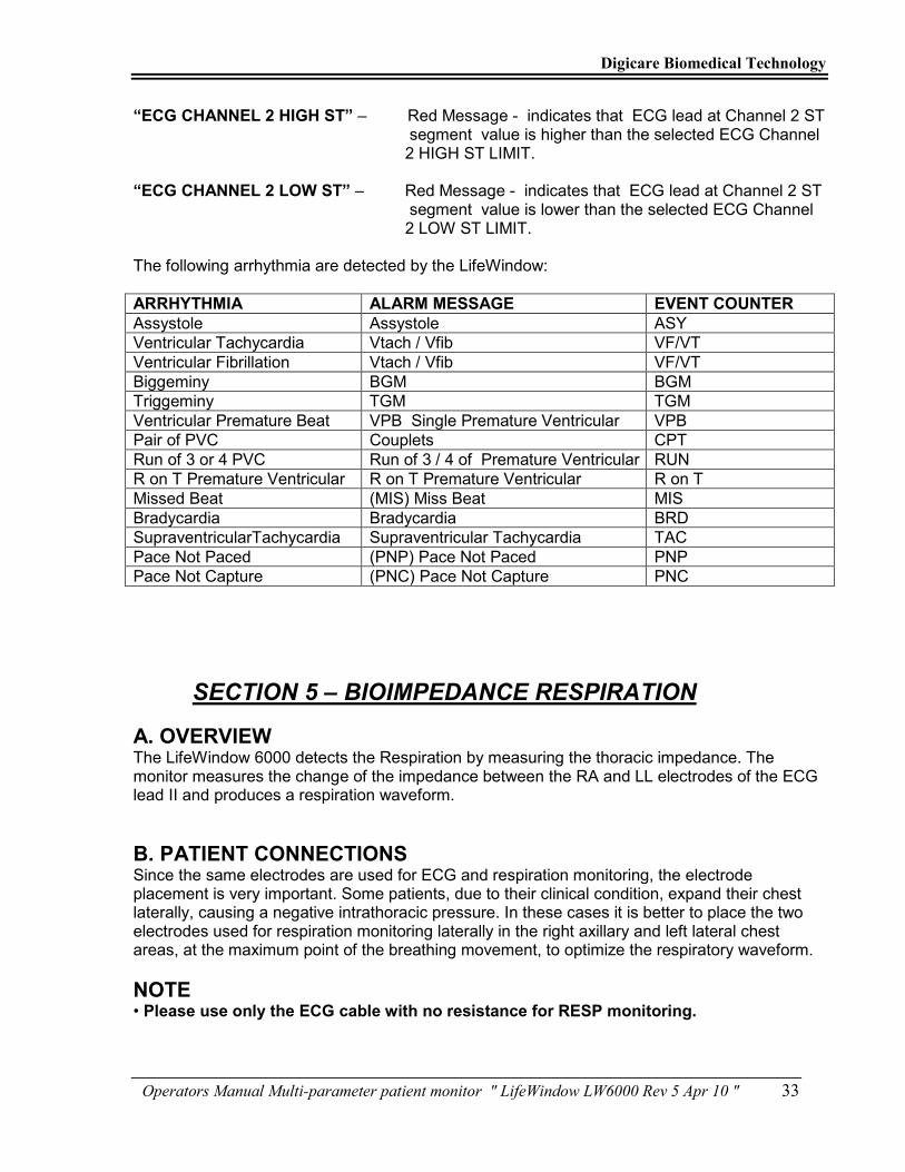
“ECG CHANNEL 2 HIGH ST” – Red Message - indicates that ECG lead at Channel 2 ST segment value is higher than the selected ECG Channel 2 HIGH ST LIMIT. “ECG CHANNEL 2 LOW ST” – Red Message - indicates that ECG lead at Channel 2 ST segment value is lower than the selected ECG Channel 2 LOW ST LIMIT. The following arrhythmia are detected by the LifeWindow:
ARRHYTHMIA ALARM MESSAGE EVENT COUNTER
Assystole Assystole ASY
Ventricular Tachycardia Vtach / Vfib VF/VT
Ventricular Fibrillation Vtach / Vfib VF/VT
Biggeminy BGM BGM
Triggeminy TGM TGM
Ventricular Premature Beat VPB Single Premature Ventricular VPB
Pair of PVC Couplets CPT
Run of 3 or 4 PVC Run of 3 / 4 of Premature Ventricular RUN
R on T Premature Ventricular R on T Premature Ventricular R on T
Missed Beat (MIS) Miss Beat MIS
Bradycardia Bradycardia BRD
SupraventricularTachycardia Supraventricular Tachycardia TAC
Pace Not Paced (PNP) Pace Not Paced PNP
Pace Not Capture (PNC) Pace Not Capture PNC
SECTION 5 – BIOIMPEDANCE RESPIRATION
A. OVERVIEW
The LifeWindow 6000 detects the Respiration by measuring the thoracic impedance. The monitor measures the change of the impedance between the RA and LL electrodes of the ECG lead II and produces a respiration waveform.
B. PATIENT CONNECTIONS
Since the same electrodes are used for ECG and respiration monitoring, the electrode placement is very important. Some patients, due to their clinical condition, expand their chest laterally, causing a negative intrathoracic pressure. In these cases it is better to place the two electrodes used for respiration monitoring laterally in the right axillary and left lateral chest areas, at the maximum point of the breathing movement, to optimize the respiratory waveform.
NOTE • Please use only the ECG cable with no resistance for RESP monitoring.

Digicare Biomedical Technology
Operators Manual Multi-parameter patient monitor " LifeWindow LW6000 Rev 5 Apr 10 " 34
ELETRODE PLACEMENT ECG LEAD II
C. RESPIRATION MENU Touch the RESP menu or the RESP indicator’s area to open the RESP menu screen.
Digicare Biomedical Technology
Operators Manual Multi-parameter patient monitor " LifeWindow LW6000 Rev 5 Apr 10 " 35
D. RESPIRATION SIZE The amplitude of the Respiration waveform in the screen is set in the Respiration Size. This setting do not affect the Respiration Rate detection and count. The Respiration Size Default is 3. To change the Respiration Size, open the Resp menu and set the Respiration Size from 1 to 10.
E. RESPIRATION RATE ALARM LIMITS Respiration Rate Limits are set by default to: High Resp Rate Limit: OFF. Low Resp Rate Limit: 5 RPM. Change the Respiration Rate Limits in the Resp menu. High Resp Rate Limit Range: 5 to 150 RPM – or OFF - non overlaping. Low Resp Rate Limit Range: 0 to 145 RPM – or OFF - non overlaping. The Alarm Limit values selected are stored by the unit after power-off. To return to the factory default values, go to the SYSTEM menu and select the Load Factory Default Settings.
F. RESPIRATION APNEA ALARM DELAY The Respiration Apnea Alarm delay default is 20 seconds. To change the Respiration Apnea Alarm delay or to turn-off, open the Resp menu and set the Respiration Apnea Alarm delay. Respiration Apnea Alarm Delay Options 10, 15, 20, 25, 30, 35, 40 seconds and Apnea Alarm OFF.
G. RESPIRATION COINCIDENCE The Respiration Coincidence Alarm is triggered in case the Respiration Rate Indicator is close to the ECG Heart Rate Indicator. In this situation the Respiration circuits may be detecting artifact from the ECG signal. This is very important in Neonatal patients with very low impedance respiration volume change. The Respiration Coincidence Alarm is set to ON in the default. To turn-off the Respiration Coincidence Alarm open the Resp menu and change the Respiration Coincidence Alarm to OFF.
H. RESPIRATION ON/OFF The Respiration function can be turned-Off and turned back On in the Resp menu.
I. RESPIRATION ALARM MESSAGES “Imp Resp APNEA” – Indicates that No detection of RESP pulses was detected over the selected time to APNEA ALARM. “Imp Resp LOW RR” – Indicates that RESP RATE value is lower than the selected LOW RR LIMIT. “Imp Resp HIGH RR” - Indicates that RESP RATE value is higher than the selected HIGH RR LIMIT. “Imp Resp COINCIDENCE” – Indicates that RESP RATE values are close to the HEART RATE values and Respiration detection is NOT accurate.

Digicare Biomedical Technology
Operators Manual Multi-parameter patient monitor " LifeWindow LW6000 Rev 5 Apr 10 " 36
SECTION 6 – PULSE OXIMETRY MONITORING
The LifeWindow™ LW6000 Pulse Oximetry provide continuous, non-invasive, automatically calibrated measurements of oxygen saturation.
The Pulse Oximeter (SpO2) determines arterial oxyhemoglobin saturation by measuring the absorption of red and infrared light passing through the tissue. Changes in absorption caused by pulsations of blood are used to determine Arterial Saturation (%SpO2) and Pulse Rate (PR).
A. PATIENT CONNECTIONS
To ensure conformance with all safety and performance, use only the recommended accessories. These are available from DIGICARE using the following part number:
SpO2 Finger Sensor with 10’ (3m) cable for Digicare
PO731
Patient Cable for Digicare™ and Nellcor® OxiMax® SpO2 Sensors
PO734
SpO2 Finger Sensor with 3’ (1m) cable for Digicare™
PO732
SpO2 Ear sensor with 3’ (1m) cable for Digicare™ PO725
SpO2 wrap sensor with 3’ (1m) cable for Digicare™ PO723
Nellcor® OxiMax® Finger Sensor with 3’ (1m) cable
PO733

Digicare Biomedical Technology
Operators Manual Multi-parameter patient monitor " LifeWindow LW6000 Rev 5 Apr 10 " 37
Nellcor® OxiMax® SpO2 Wrap Probe with 3’ (1m) cable
PO735
Band for Nellcor® OxiMax® SpO2 Wrap Probe (Box of 50)
PO721
B. SPO2 MONITORING
FINGER PROBE – ADULT
WRAP PROBE - NEONATAL
• Connect the sensor assembly to the Interface Cable and lock the plastic hinged cover to prevent accidental cable disconnection (If using 3” cable sensors). • Connect the sensor patient cable into the LifeWindow LW 6000 SpO2 side panel connector (12). Push the connector in until you hear an audible “click”. • The message SpO2 SENSOR is displayed on screen until the probe is placed in the patient. • A few seconds after the sensor is placed in the patient, the SpO2 SENSOR message changes to Searching SpO2, the Bar-graph shows the SpO2 Pulse Level and SpO2 and Pulse Rate values are displayed.
DIG
ICARE

Digicare Biomedical Technology
Operators Manual Multi-parameter patient monitor " LifeWindow LW6000 Rev 5 Apr 10 " 38
• Verify if the sensor is properly positioned by observing at least ten seconds of a continuous plethysmogram waveform being displayed. • If the Bar-graph Pulse Level is at a low level, “weak pulse” message will be displayed. Reposition the sensor or try a different sensor. • The LifeWindow™ LW 6000 audible “beep” is by default generated by the ECG detection, modulated in tone by the SpO2 value. The source of the “beep” can be changed to SpO2 pulse detection. To change the “beep” source, touch the System menu and touch Sound Volume menu. Select the Beep Source to SpO2. NOTE: Reusable sensors may be used on the same site for a maximum of four (4) hours, provided the site is inspected routinely to ensure skin integrity and correct positioning. Because individual skin condition affects the ability of the skin to tolerate sensor placement, it may be necessary to change the sensor site more frequently with some patients.
Loss of pulse can occur if:
• The sensor is to tight. • There is excessive illumination (e.g., a surgical or bilirubin lamp or direct sunlight). • The sensor is placed on an extremity with a blood pressure cuff, arterial catheter or intravascular line. • The patient experiences shock, hypertension, severe vasoconstriction, severe anemia, hypothermia, arterial occlusion to the sensor, or cardiac arrest.
Inaccurate measurements may be caused by:
• Incorrect application of dysfunctional hemoglobin’s, such as carboxyhemoglobin or methemoglobin. • Significant, levels of indocyanine green, ethylene blue or other intravascular dyes. • Exposure to excessive illumination, such as surgical lamps, especially ones with a xenon light source; bilirubin lamps, fluorescent lights; infrared heating lamps; or direct sunlight. • Excessive patient movement. • Venous pulsation’s. • Electrosurgical interference. • Placement of the sensor on an extremity that has a blood pressure cuff, arterial catheter or intravascular line.
Do not attach a probe to the same limb with a blood pressure cuff. The data received will not be valid when the cuff is inflated. Attach the probe to the limb opposite the site used for the blood pressure cuff.
C. SpO2 WAVEFORM AND BAR GRAPH
• The SpO2 waveform sweep speed can be selected from: 6.25, 12.5, 25, 50 and 100 mm/sec in TRACE menu. • The amplitude of the pulse waveform is automatically adjusted in screen. • The Bar graph indicates the pulse signal height and varies from 1 to 8. Increasing the signal amplitude increases the Bar graph value. Bellow number 2 in bar graph, the message WEAK PULSE is displayed.

Digicare Biomedical Technology
Operators Manual Multi-parameter patient monitor " LifeWindow LW6000 Rev 5 Apr 10 " 39
D. SpO2 ALARM LIMITS
• SpO2 Alarm Limits are set by default to: SpO2 Upper Limit: OFF SpO2 Lower Limit: 88 % • Change the SpO2 Alarm Limits in the SpO2 menu. SpO2 Upper Limit Range: 1 to 100 % – or OFF - non overlapping. SpO2 Lower Limit Range: 0 to 99 % – or OFF - non overlapping. • Pulse Alarm Limits are set by default to: Pulse Upper Limit: 140 PPM Pulse Lower Limit: 60 PPM • Change the Pulse Alarm Limits in the SpO2 menu. Pulse Upper Limit Range: 5 to 450 PPM – or OFF - non overlapping. Pulse Lower Limit Range: 0 to 445 PPM – or OFF - non overlapping. • The values selected are stored by the unit after power-off. • To return to the factory default values, go to the SYSTEM menu and select the Load Factory Default Settings.
E. SpO2 ALARM MESSAGES
SENSOR SpO2 - Indicate that SpO2 probe is disconnected from the patient or the patient cable is disconnected from the monitor or a malfunction in sensor or in patient cable.
SpO2 LOW AND HIGH ALARM LIMITS - Indicate that SpO2 value overlap the LOW or HIGH ALARM LIMIT selected. WEAK PULSE - Indicate the pulse signal amplitude is low causing instability in SpO2
monitoring. Check the probe installation, site perfusion and body temperature.
CHECK SITE - Indicate instability in the SpO2 readings. Verify the probe installation and change probe site.
NO PULSE - Indicate the SpO2 pulse amplitude is smaller then the minimum pulse.
SECTION 7 – CO2 MONITORING
A. OVERVIEW
• The LifeWindow™ LW 6000 Patient Monitor has a plug and play CO2 technology, with Micro- Flow™ sidestream CO2, MainFlow™ mainstream CO2 and Dual Capnography, designed with sophisticated infrared absorption spectroscopy. • The Micro-Flow™ sidestream module can be assembled internally in the unit or it can be one small and lightweight external module. The sample lines used are the same for both internal and external Micro-Flow™ sidestream modules. • The MainFlow™ mainstream sensor is assembled in the air way adapter. The connection of the MainFlow™ mainstream sensor is the same as the external Micro-Flow™ sidestream CO2 module. • The Dual Capnography is enabled by the interchangeability of the Micro-Flow™ sidestream and MainFlow™ mainstream external sensors. The LifeWindow™ LW 6000 automatically recognize what type of CO2 external sensor is connected and configures the CO2 function.

Digicare Biomedical Technology
Operators Manual Multi-parameter patient monitor " LifeWindow LW6000 Rev 5 Apr 10 " 40
• The LifeWindow™ LW 6000 with internal Micro-Flow™ sidestream module does not have the connection for the external Micro-Flow™ sidestream and the MainFlow™ mainstream sensor.
SECTION 7.1 – MAINSTREAM CO2 MONITORING
A. Principle of Operation
• The LifeWindow™ LW 6000 MainFlow™ mainstream CO2 sensor is used for the continuous measurement of CO2 and respiratory rate. The sensor measures CO2 by using the infrared absorption technique. The principle is based on the fact that CO2 molecules absorb infrared (IR) light energy of specific wavelengths, with the amount of energy absorbed being directly related to the CO2 concentration. When an IR beam is passed through a gas sample containing CO2, the electronic signal from the photodetector (which measures the remaining light energy) is measured. This signal is then compared to the energy of the IR source and adjusted to accurately reflect CO2 concentration in the sample. The MainFlow™ mainstream CO2 sensor’s response to a known concentration of CO2 is stored at the factory in the sensor’s memory. A reference channel accounts for optical changes in the sensor, allowing the system to remain in calibration without user intervention. • The LifeWindow™ LW 6000 MainFlow™ mainstream CO2 sensor is designed specifically for measurement of CO2 using sophisticated infrared absorption spectroscopy. With mainstream, measurements are taken at the patient’s airway at a sampling frequency of 100 Hz, so response is faster and there is less chance of erroneous, artifact data. The analyzer portion of the sensor cannot be contaminated with patient secretions, and there are no pumping or pneumatic components to replace. So, maintenance requirements and overall cost-of-ownership are minimized. The family of airway adapters are easy to use and durable enough even for long-term ventilator patients.
B. Indications for Use
• The MainFlow™ mainstream CO2 Sensor is to be used by a physician or licensed health care professional trained in the use of the equipment. • The use of the MainFlow™ mainstream CO2 Sensor is contraindicated in patients where the physician or licensed health care professional deems it invalidated by the nature of the patient, procedure or equipment. WARNINGS • Explosion Hazard: DO NOT use in the presence of flammable anesthetics. Use of the MainFlow™ mainstream CO2 Sensor in such environment may present an explosion hazard. • Electrical Shock Hazard: Always disconnect the MainFlow™ CO2 Sensor before cleaning. Do NOT use if it appears to have been damaged. Refer servicing to qualified service personnel. • Follow precautions for electrostatic discharge (ESD) and electromagnetic interference (EMI) to and from other equipment. • Failure of Operation: If the MainFlow™ mainstream CO2 Sensor fails to respond as described in this user guide; DO NOT use it until approved for use by qualified personnel. • DO NOT position the sensor cables or tubing in any manner that may cause entanglement or strangulation. Support the mainstream CO2 airway adapter to prevent stress on the ET tube. • Reuse, disassembly, cleaning, disinfecting or sterilizing the single patient use CO2 airway adapters may compromise functionality and system performance leading to a user or patient hazard. Performance is not guaranteed if an item labeled as single patient use is reused. • Inspect the CO2 airway adapters for damage prior to use. DO NOT use the CO2 airway adapters if they appear to be damaged or broken. • Replace the CO2 airway adapters if excessive secretions are observed.
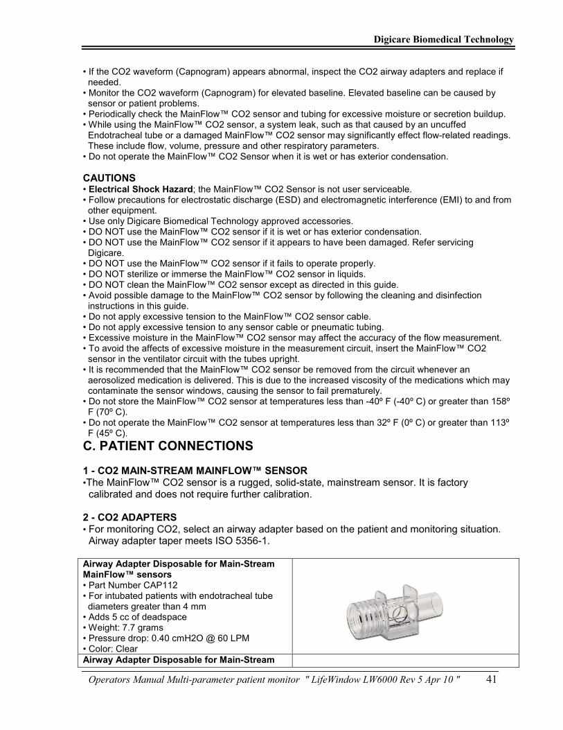
Digicare Biomedical Technology
Operators Manual Multi-parameter patient monitor " LifeWindow LW6000 Rev 5 Apr 10 " 41
• If the CO2 waveform (Capnogram) appears abnormal, inspect the CO2 airway adapters and replace if needed. • Monitor the CO2 waveform (Capnogram) for elevated baseline. Elevated baseline can be caused by sensor or patient problems. • Periodically check the MainFlow™ CO2 sensor and tubing for excessive moisture or secretion buildup. • While using the MainFlow™ CO2 sensor, a system leak, such as that caused by an uncuffed Endotracheal tube or a damaged MainFlow™ CO2 sensor may significantly effect flow-related readings. These include flow, volume, pressure and other respiratory parameters. • Do not operate the MainFlow™ CO2 Sensor when it is wet or has exterior condensation.
CAUTIONS • Electrical Shock Hazard; the MainFlow™ CO2 Sensor is not user serviceable. • Follow precautions for electrostatic discharge (ESD) and electromagnetic interference (EMI) to and from other equipment. • Use only Digicare Biomedical Technology approved accessories. • DO NOT use the MainFlow™ CO2 sensor if it is wet or has exterior condensation. • DO NOT use the MainFlow™ CO2 sensor if it appears to have been damaged. Refer servicing Digicare. • DO NOT use the MainFlow™ CO2 sensor if it fails to operate properly. • DO NOT sterilize or immerse the MainFlow™ CO2 sensor in liquids. • DO NOT clean the MainFlow™ CO2 sensor except as directed in this guide. • Avoid possible damage to the MainFlow™ CO2 sensor by following the cleaning and disinfection instructions in this guide. • Do not apply excessive tension to the MainFlow™ CO2 sensor cable. • Do not apply excessive tension to any sensor cable or pneumatic tubing. • Excessive moisture in the MainFlow™ CO2 sensor may affect the accuracy of the flow measurement. • To avoid the affects of excessive moisture in the measurement circuit, insert the MainFlow™ CO2 sensor in the ventilator circuit with the tubes upright. • It is recommended that the MainFlow™ CO2 sensor be removed from the circuit whenever an aerosolized medication is delivered. This is due to the increased viscosity of the medications which may contaminate the sensor windows, causing the sensor to fail prematurely. • Do not store the MainFlow™ CO2 sensor at temperatures less than -40º F (-40º C) or greater than 158º F (70º C). • Do not operate the MainFlow™ CO2 sensor at temperatures less than 32º F (0º C) or greater than 113º F (45º C).
C. PATIENT CONNECTIONS
1 - CO2 MAIN-STREAM MAINFLOW™ SENSOR •The MainFlow™ CO2 sensor is a rugged, solid-state, mainstream sensor. It is factory calibrated and does not require further calibration. 2 - CO2 ADAPTERS • For monitoring CO2, select an airway adapter based on the patient and monitoring situation. Airway adapter taper meets ISO 5356-1. Airway Adapter Disposable for Main-Stream MainFlow™ sensors • Part Number CAP112 • For intubated patients with endotracheal tube diameters greater than 4 mm • Adds 5 cc of deadspace • Weight: 7.7 grams • Pressure drop: 0.40 cmH2O @ 60 LPM • Color: Clear
Airway Adapter Disposable for Main-Stream

Digicare Biomedical Technology
Operators Manual Multi-parameter patient monitor " LifeWindow LW6000 Rev 5 Apr 10 " 42
MainFlow™ sensors (Low Dead Space for Neonatal) • Part Number CAP113 • For intubated patients with endotracheal tube diameters less than or equal to 4 mm • Adds less than 1 cc of deadspace • Weight: 9.1 grams • Pressure drop: 0.74 cmH2O @ 10 LPM • Color: Purple
Airway Adapter Reusable for Main-Stream MainFlow™ sensors • Part Number CAP110 • For intubated patients with endotracheal tube diameters greater than 4 mm • Adds 5 cc of deadspace • Weight: 12.0 grams • Pressure drop: 0.38 cmH2O @ 60 LPM • Color: Black
Airway Adapter Reusable for Main-Stream MainFlow™ sensors (Low Dead Space for Neonatal) • Catalog No. 7053 • For intubated patients with endotracheal tube diameters less than or equal to 4 mm • Adds less than 1 cc of deadspace • Weight: 14.9 grams • Pressure drop: 0.68 cmH2O @ 10 LPM • Color: Red
Note: All components are Latex free. Note: All dimensions are in millimeters. Note: Color pigment does not alter the specifications of the material. • Attach the MainFlow™ CO2 sensor onto a clean and dry CO2 adapter.
3 – CONNECTION WITH LIFEWINDOW • The LifeWindow™ LW 6000 CO2 function is a Plug and Play technology built in the hardware and software of the unit. Without the MainFlow™ CO2 sensor connected, the message “CO2 is Off” is displayed in the CO2 screen indicator area and no CO2 trace is present. If the CO2

Digicare Biomedical Technology
Operators Manual Multi-parameter patient monitor " LifeWindow LW6000 Rev 5 Apr 10 " 43
menu or CO2 indicator area is touched in this situation, nothing happen as the CO2 function is turned off.
• Insert the MainFlow™ CO2 Sensor connector into the receptacle ( 17 ) of the LifeWindow™ LW 6000 Patient Panel.
• Make sure the arrows on the connector line up the two keys of the connector with the receptacle and insert.
• To remove the connector, grasp the body portion of the connector back and remove. Note: Do not remove by pulling cable. • The CO2 monitoring screen is automatically configured, with the CO2 indicator area, CO2 traces, scales and CO2 alarm messages. • Wait for the Sensor Warm Up message to clear. If a Zero Calibration message is displayed, perform a Zero Calibration process.
4 – ZEROING THE MAINFLOW™ CO2 MAINSTREAM SENSOR • The MainFlow™ CO2 sensor is compatible only with Digicare Biomedical Technology CO2 airway adapters. • Each airway adapter has a unique set of optical characteristics. The adapter zero allows the MainFlow™ CO2 sensor to adjust to the optical characteristics of each of the different adapter types. • An “Adapter Zero” is a quick process that allows the LifeWindow™ LW 6000 to adjust to the special characteristics of a particular MainFlow™ CO2 sensor; it is necessary only when requested. Such a request may occur the first time a particular MainFlow™ CO2 sensor is connected to the LifeWindow™ LW 6000, or if a change is detected in the MainFlow™ CO2 sensor or in the adapter. • Keep the MainFlow™ CO2 sensor attached to the adapter exposed to room air and away from all sources of CO2, including the ventilator, the patient’s breath and your own. • Touch in the CO2 menu and touch in the Calibration “Zero”. A Warning message: “Is input exposed to 0 mmHg concentration” is displayed. Touch in the Yes button to perform a Zero Calibration. The message Zero in Progress is displayed during the zero process, typically 15 to 20 seconds (maximum time of 40 seconds).
5 – PATIENT CIRCUIT • Attach the MainFlow™ CO2 sensor and airway adapter to the patient circuit as close as possible to the patient’s mouse.

Digicare Biomedical Technology
Operators Manual Multi-parameter patient monitor " LifeWindow LW6000 Rev 5 Apr 10 " 44
D. CO2 MONITORING
• The LifeWindow™ LW 6000 start displaying the CO2 waveform in two cascaded traces and function and ETCO2, insCO2 and Respiration Rate measured values, with all alarm limits and settings in the defaults values or the last saved settings. 1 – CO2 WAVEFORM AND SCALE • The CO2 waveform traces are by default selected to traces 5 and 6 cascaded. The traces and cascade options can be changed in the TRACES menu. The traces settings return to the default every time the unit is turned-on. • The CO2 waveform default sweep speed is 6.25 mm/sec. To change the CO2 waveform sweep speed, touch the Traces menu and select the desired sweep speed. The options are: 6.25, 12.5, 25, 50 and 100 mm/sec • The CO2 waveform scale default is 0 to 50 mmHg. To change the CO2 waveform scale touch the CO2 menu and select the desired waveform scale. The options are: 0 to 5 mm Hg, 0 to 10 mmHg, 0 to 50 mmHg and 0 to 100 mmHg. 2 – CO2 ALARM LIMITS • CO2 Alarm Limits are set by default to: ETCO2 Upper Limit: 45 mmHg ETCO2 Lower Limit: 20 mmHg InsCO2 Upper Limit: 10 mmHg InsCO2 Lower Limit: OFF Resp Rate Upper Limit: 50 BPM Resp Rate Lower Limit: 5 BPM • Change the CO2 Alarm Limits in the CO2 menu. ETCO2 Upper Limit Range: 1 to 100 % – or OFF - non overlapping. ETCO2 Lower Limit Range: 0 to 99 % – or OFF - non overlapping. InsCO2 Upper Limit Range: 1 to 100 % – or OFF - non overlapping. InsCO2 Lower Limit Range: 0 to 99 % – or OFF - non overlapping. Resp Rate Upper Limit Range: 1 to 150 BPM – or OFF - non overlapping. Resp Rate Lower Limit Range: 0 to 149 BPM – or OFF - non overlapping. • To return to the factory default values, go to the SYSTEM menu and select the Load Factory Default Settings.

Digicare Biomedical Technology
Operators Manual Multi-parameter patient monitor " LifeWindow LW6000 Rev 5 Apr 10 " 45
3 – CO2 ALARM MESSAGES
High and Low ETCO2 – Are triggered if the ETCO2 value overlaps the High or Low Limits respectively
High and Low InsCO2 – Are triggered if the InsCO2 value overlaps the High or Low Limits respectively.
High and Low Resp – Are triggered if the Resp Rate value overlaps the High or Low Limits respectively.
Sensor Falty - Indicates a hardware error in the sensor or sensor connection. Reinsert or reset the sensor if necessary. If error persists, contact Digicare. Comps not Set - Indicates the Barometric Pressure or gas compensations have not been set since power on. This message normally flashes quickly after power on of the sensor and is automatically cleared as the sensor set all compensations. If the message stays steady reinsert or reset the sensor. If error persists, contact Digicare. Zero in Progress - Indicates the MainFlow™ CO2 sensor Zero is currently in progress. Sensor Warm Up – Indicates the MainFlow™ CO2 mainstream sensor is warming up. It takes about 2 minutes typically for the sensor achieve monitoring temperature.
Zero Required - Indicates a Zero calibration process is required. This is required every time as new airway adapter is in use. Check the airway adapter and clean if necessary. Perform the Zero Adapter calibration process. If you need to perform the Zero more than once, a possible adapter or sensor faulty may exist. CO2 Out of Range - Indicates the value being calculated is out of the CO2 range. Check the airway adapter and perform a Zero calibration process. If error persists, contact Digicare Check Adapter - Usually indicates the airway adapter was removed from the MainFlow™ CO2 sensor or when there is an optical blockage on the windows of the airway adapter. May also be caused by failure to perform MainFlow™ CO2 sensor Zero when adapter type is changed. Clean or change airway adapter if mucus or moisture is seen. If the adapter is clean, perform a Zero calibration process. If problem persists contact Digicare.
Zero Error - Indicates the Zero calibration process was not successful. Clean or change the airway adapter. Disconnect and reconnect the MainFlow™ CO2 sensor in the LifeWindow connector. Perform a Zero calibration process. If problem persists contact Digicare.

Digicare Biomedical Technology
Operators Manual Multi-parameter patient monitor " LifeWindow LW6000 Rev 5 Apr 10 " 46
4 – CO2 SENSOR ACCURACY CHECK • The MainFlow™ CO2 sensor is a rugged, solid-state, mainstream sensor. It is factory calibrated and does not require further calibration. The only calibration required is the Zero Calibration , witch does not require any special setup, as explained before. • In applications where it is mandatory to perform a routine Accuracy check, the MainFlow™ CO2 Mainstream sensor shall be compared against calibration gas every 12 months. Contact Digicare Biomedical Technology for more information.
SECTION 7.2 – SIDESTREAM CO2 MONITORING
A. PRINCIPLE OF OPERATION
The LifeWindow™ LW 6000 MicroFlow™ Sidestream CO2 module is specifically designed for sidestream measurement of CO2 and Respiratory Rate, using sophisticated infrared absorption spectroscopy. MicroFlow™ Sidestream is a sidestream sampling system with a 50 ml/ minute low sampling rate that is used to measure the CO2 of non-intubated and intubated patients. Because of its unique design, response is fast and there is less chance of erroneous, artifact data. The analyzer portion of the sensor cannot be contaminated with patient secretions, therefore maintenance requirements and overall cost-of-ownership are minimized. The exclusive Digicare Biomedical Technology family of sidestream sampling and on-airway adapter kits are easy to use and durable enough even for long-term ventilator patients. Yet, they are inexpensive and disposable. The LifeWindow™ LW 6000 MicroFlow™ Sidestream CO2 module can be installed built-in or used as an external module interchangeable with the MainFlow™ CO2 Mainstream Sensor making it easy for you to configure your patient monitoring systems with state-of-the-art CO2 monitoring technology that is affordable and easy to use.
B. INDICATIONS FOR USE
• The intended use of the MicroFlow™ Sidestream CO2 module is to provide carbon dioxide monitoring to a during anesthesia / recovery, in the intensive care unit (ICU), and in emergency Medicine/Transport or Respiratory care. WARNINGS • Explosion Hazard: DO NOT use in the presence of flammable anesthetics. Use of the MicroFlow™ sidestream CO2 Module in such environment may present an explosion hazard. • Electrical Shock Hazard: Always disconnect the MicroFlow™ CO2 Sidestream Module before cleaning. Do NOT use if it appears to have been damaged. Refer servicing to qualified service personnel. • Follow precautions for electrostatic discharge (ESD) and electromagnetic interference (EMI) to and from other equipment. • Failure of Operation: If the MicroFlow™ sidestream CO2 Module fails to respond as described in this user guide; DO NOT use it until approved for use by qualified personnel. • DO NOT position the sensor cables or tubing in any manner that may cause entanglement or strangulation. Support the sidestream CO2 airway adapter to prevent stress on the ET tube. • Reuse, disassembly, cleaning, disinfecting or sterilizing the single patient use cannula kits and on airway adapters may compromise functionality and system performance leading to a user or patient hazard. Performance is not guaranteed if an item labeled as single patient use is reused. • Inspect the sidestream on airway adapters and sidestream sampling kits for damage prior to use. DO NOT use the sidestream on airway adapters and sidestream sampling kits if they appear to be damaged or broken.

Digicare Biomedical Technology
Operators Manual Multi-parameter patient monitor " LifeWindow LW6000 Rev 5 Apr 10 " 47
• Replace the sidestream on airway adapters and sidestream sampling kits if excessive secretions are observed. • Monitor the CO2 waveform (Capnogram). If you see changes or abnormal appearance check the patient and the sampling line. Replace line if needed. • Do not operate the MicroFlow™ CO2 Sidestream Module when it is wet or has exterior condensation. • Do not apply excessive tension to any cable. • Electrical Shock Hazard; No user serviceable parts inside. • DO NOT use device on patients that can not tolerate the withdrawal of 50 ml/min +/- 10 ml/min from the airway or patients that can not tolerate the added dead space to the airway. • Do not connect the exhaust tube to the ventilator circuit.
CAUTIONS • Electrical Shock Hazard; the MicroFlow™ sidestream CO2 Module is not user serviceable. Refer servicing to qualified personnel. • Follow precautions for electrostatic discharge (ESD) and electromagnetic interference (EMI) to and from other equipment. • Use only Digicare Biomedical Technology approved accessories. • DO NOT use the MicroFlow™ sidestream CO2 Module if it fails to operate properly, appears to have been damaged, is wet or has exterior condensation. • DO NOT sterilize or immerse the MicroFlow™ sidestream CO2 Module in liquids. • DO NOT clean the MicroFlow™ sidestream CO2 Module and accessories except as directed in this guide. • DO NOT apply excessive tension to the MicroFlow™ sidestream CO2 Module cable. • DO NOT store the MicroFlow™ sidestream CO2 Module at temperatures less than -40º F (-40º C) or greater than 158º F (70º C). • DO NOT operate the MicroFlow™ sidestream CO2 Module at temperatures less than 32º F (0º C) or greater than 104º F (40º C). • Remove the LoFlo sampling kit sample cell from the receptacle when not in use. • DO NOT stick appendage into sample receptacle. • Always insert sample cell before inserting the on-airway adapter into the ventilated circuit. • Always remove the on-airway adapter from the ventilated circuit before removing the sample cell.
C. PATIENT CONNECTIONS 1- CO2 MICROFLOW™ SIDESTREAM MODULE • The MicroFlow™ CO2 sidestream Module is a rugged, solid-state, sidestream sensor. It is factory calibrated and does not require further calibration. The Module can be internally installed or external to the LifeWindow™ LW 6000. • When using the external module, connect it to the ( 17 ) connector in the LifeWindow patient connections panel.
2 - SINGLE PATIENT USE SIDESTREAM ON-AIRWAY ADAPTERS • For monitoring CO2, select a sidestream on-airway adapter kit that is appropriate for the patient size and application.
Sidestream Sampling line – Regular for MicroFlow™ Capnography (high humidity) Part Number: CAP120 Weight: 4.5 grams Deadspace – adds approximately 7 cc For use with ET Tube sizes > 4.0 mm

Digicare Biomedical Technology
Operators Manual Multi-parameter patient monitor " LifeWindow LW6000 Rev 5 Apr 10 " 48
Sidestream Sampling line – Regular for MicroFlow™ Capnography (low humidity) Part Number: CAP121 Weight: 4.5 grams Deadspace – adds approximately 7 cc For use with ET Tube sizes > 4.0 mm
Sidestream Sampling line – Low Dead Space for MicroFlow™ Capnography (high humidity) Part Number: CAP122 Weight: 5.8 grams Deadspace – adds approximately 1 cc For use with ET Tube sizes < = 4.0 mm
Sidestream Sampling line – Low Dead Space for MicroFlow™ Capnography (low humidity) Part Number: CAP123 Weight: 5.8 grams Deadspace – adds approximately 1 cc For use with ET Tube sizes < = 4.0 mm
3 – CONNECTION WITH LIFEWINDOW • The LifeWindow™ LW 6000 CO2 function is a Plug and Play technology built in the hardware and software of the unit. • The LifeWindow™ LW 6000 screen, with internal MicroFlow™ CO2 sidestream module installed, displays the CO2 indicators and waveform after turned-on. It displays a Pump is Off message until a Sample Line is connected. • The LifeWindow™ LW 6000 screen, with external MicroFlow™ CO2 sidestream module, displays the message “CO2 is Off” in the CO2 indicator area and no CO2 trace is present until the CO2 module is connected. If the CO2 menu or CO2 indicator area is touched in this situation, nothing happen as the CO2 function is turned off. Insert the MicroFlow™ CO2 sidestream module connector into the receptacle ( 17 ) of the LifeWindow™ LW 6000. It displays a Pump is Off message until a Sample Line is connected. • The LifeWindow™ LW 6000 MicroFlow™ CO2 sidestream Module has one exhaust port located in the rear panel of the unit (28) for internal modules or in the external module itself for attaching scavenging tubing. • Insert the sample cell of the sampling kit into the sample cell receptacle of the MicroFlow™ CO2 sidestream Module or in the ( 10 ) receptacle in the LifeWindow™ LW 6000 as shown. A “click” will be heard when the sample cell is properly inserted.
Figure 1 • Inserting the sample cell into the receptacle automatically starts the sampling pump. Removal of the sample cell turns the sample pump off. • To remove the sampling kit sample cell from the sample cell receptacle, press down on the

Digicare Biomedical Technology
Operators Manual Multi-parameter patient monitor " LifeWindow LW6000 Rev 5 Apr 10 " 49
locking tab and pull the sample cell from the sample cell receptacle.
Sample Cell Figure 2 • Wait for the Sensor Warm Up message to clear. If a Zero Calibration message is displayed, perform a Zero Calibration process. 4 - ZEROING THE MICROFLOW™ CO2 SIDESTREAM MODULE • The MicroFlow™ CO2 sidestream Module is compatible only with Digicare Biomedical sidestream CO2 accessories. The sample cell zero allows the MicroFlow™ CO2 sidestream Module to adjust to the optical characteristics of the sample cell. • A “Sample Cell Zero” is a quick process that allows the LifeWindow™ LW 6000 to adjust to the special characteristics of a particular MicroFlow™ CO2 sidestream Module; it is necessary only when requested. Such a request will occur if a change is detected in the MicroFlow™ CO2 sidestream Module. • Keep the MicroFlow™ airway adapter exposed to room air and away from all sources of CO2, including the ventilator, the patient’s breath and your own. • Touch in the CO2 menu and touch in the Calibration “Zero”. A Warning message: “Is input exposed to 0 mmHg concentration” is displayed. Touch in the Yes button to perform a Zero Calibration. The message Zero in Progress is displayed during the zero process, typically 15 to 20 seconds (maximum time of 40 seconds). 5 – PATIENT CIRCUIT • The regular sidestream on-airway adapter kits should be used when monitoring intubated patients with Endotracheal Tube diameters greater than 4.0 mm. Use the Low Dead Space on-airway adapter kits when monitoring intubated patients with Endotracheal Tube diameters less than or equal to 4.0mm. • CAUTION: The Regular and the Low Dead Space on-airway adapters are intended for single patient use. Do NOT reuse or sterilize the adapter kit as system performance will be compromised. • Verify that the on-airway adapter is clean, dry and undamaged. Replace the on-airway adapter kit if necessary. • Insert the sample cell into the sample cell receptacle as shown in the figure 1. A “click” will be heard when properly inserted. • Perform a sample cell zero if prompted by the LifeWindow™ LW 6000. • Place the on-airway adapter at the proximal end of the airway circuit between the elbow and the ventilator circuit wye. • Check that connections have been made correctly by verifying the presence of a proper capnogram on the Patient Monitor.

Digicare Biomedical Technology
Operators Manual Multi-parameter patient monitor " LifeWindow LW6000 Rev 5 Apr 10 " 50
Figure 3 • CAUTION: Always insert the Sample Cell of the Sample line into the Sample Cell Receptacle on the MicroFlow™ CO2 sidestream module before inserting the on-airway adapter into the ventilator circuit. Failure to follow this, may introduce a leak in the circuit, thereby reducing set minute volume. • CAUTION: Remove the MicroFlow™ sample cell from the receptacle when not in use. • NOTE: Do not place the on-airway adapter between the ET tube and the elbow as this may allow patient secretions to accumulate in the adapter. If pooling does occur, the on-airway adapter may be removed from the circuit, rinsed with water (or sterile water) and reinserted into the circuit. If rinsed, make sure that no water has entered the sampling tubing. If so, blow out water or replace the sample line. To prevent moisture from draining into the on-airway adapter kit tubing, always place the on-airway adapter tubing in an up position (see Figure 3).
6 – CHECK SAMPLE LINE MESSAGE • The sample flow rate of the MicroFlow™ CO2 sidestream module is continually monitored. If the flow rate falls outside the nominal operating range and continues for 15 seconds, the message “Check Sample Line” will be displayed. The pump will shut off after 2 minutes if the condition that caused this change is not corrected.
7 – CONDITIONS THAT CAN CAUSE A CHANGE IN FLOW RATE • Water, mucous or other patient contaminate has entered the sample tubing. • The sample tubing is crimped or pinched so that the sample flow rate has decreased. • The exhaust port of the MicroFlow™ CO2 sidestream module is obstructed. • The sample line is damaged. • The sample line has been cut, or split, causing the flow rate to increase.
8 –CLEARING THE “CHECK SAMPLE LINE” MESSAGE • When the “Check Sample Line” message is displayed, the user should inspect the sample line kit to verify that none of the conditions described above are present. Replace with a new sample kit if needed. • If the user removes the sample cell for inspection and then reinserts the sample cell without correcting the condition, the “Check Sample Line” message will reappear. • The user should verify that the exhaust port is not obstructed or blocked. If tubing is connected to the exhaust port, the user should also inspect the tubing for any crimping or pinching. • The “Check Sample Line” message will clear and the sample pump will not be turned off if the condition that caused the flow rate change is corrected within 2 minutes. • The “Check Sample Line” message will clear if the sample cell is removed or if the LifeWindow™ LW 6000 is reset.

Digicare Biomedical Technology
Operators Manual Multi-parameter patient monitor " LifeWindow LW6000 Rev 5 Apr 10 " 51
D. CO2 MONITORING
• The LifeWindow™ LW 6000 start displaying the CO2 waveform in two cascaded traces and function and ETCO2, insCO2 and Respiration Rate measured values, with all alarm limits and settings in the defaults values or the last saved settings. 1 – CO2 WAVEFORM AND SCALE • The CO2 waveform traces are by default selected to traces 5 and 6 cascaded. The traces and cascade options can be changed in the Traces menu. The traces settings return to the default every time the unit is turned-on. • The CO2 waveform default sweep speed is 6.25 mm/sec. To change the CO2 waveform sweep speed, touch the Traces menu and select the desired sweep speed. The options are: 6.25, 12.5, 25, 50 and 100 mm/sec • The CO2 waveform scale default is 0 to 50 mmHg. To change the CO2 waveform scale touch the CO2 menu and select the desired waveform scale. The options are: 0 to 5 mm Hg, 0 to 10 mmHg, 0 to 50 mmHg and 0 to 100 mmHg. 2 – CO2 ALARM LIMITS • CO2 Alarm Limits are set by default to: ETCO2 Upper Limit: 45 mmHg ETCO2 Lower Limit: 20 mmHg InsCO2 Upper Limit: 10 mmHg InsCO2 Lower Limit: OFF Resp Rate Upper Limit: 50 BPM Resp Rate Lower Limit: 5 BPM • Change the CO2 Alarm Limits in the CO2 menu. ETCO2 Upper Limit Range: 1 to 100 % – or OFF - non overlaping. ETCO2 Lower Limit Range: 0 to 99 % – or OFF - non overlapping. InsCO2 Upper Limit Range: 1 to 100 % – or OFF - non overlapping. InsCO2 Lower Limit Range: 0 to 99 % – or OFF - non overlapping. Resp Rate Upper Limit Range: 1 to 150 BPM – or OFF - non overlapping. Resp Rate Lower Limit Range: 0 to 149 BPM – or OFF - non overlapping. • To return to the factory default values, go to the SYSTEM menu and select the Load Factory Default Settings. 3 – CO2 ALARM MESSAGES
High and Low ETCO2 – Are triggered if the ETCO2 value overlaps the High or Low Limits respectively.
High and Low InsCO2 – Are triggered if the InsCO2 value overlaps the High or Low Limits respectively.
High and Low Resp – Are triggered if the Resp Rate value overlaps the High or Low Limits respectively.
Sensor Faulty - Indicates a hardware error in the module or module connection. Reinsert or reset the module if necessary. Comps not Set - Indicates the Barometric Pressure or gas compensations have not been set since power on. This message normally flashes quickly after power on of the sensor and is automatically cleared as the sensor set all compensations. If the message stays steady

Digicare Biomedical Technology
Operators Manual Multi-parameter patient monitor " LifeWindow LW6000 Rev 5 Apr 10 " 52
reinsert or reset the sensor. Zero in Progress - Indicates the MicroFlow™ CO2 sidestream module Zero is currently in progress.
Sensor Warm Up - Indicates the MicroFlow™ CO2 sidestream module is warming up. It takes about 2 minutes typically for the sensor achieve monitoring temperature.
Zero Required - Indicates a Zero calibration process is required. This is required every time as new sample line and airway adapter is used. Check the sample line and airway adapter and clean if necessary. Perform the Zero Adapter calibration process. If you need to perform the Zero more than once, a possible sample line - adapter or module faulty may exist.
CO2 Out of Range - Indicates the value being calculated is out of the CO2 range. Check the sample line and airway adapter and perform a Zero calibration process. Zero Error - Indicates the Zero calibration process was not successful. Clean or change the airway adapter. Disconnect and reconnect the MicroFlow™ CO2 sidestream module in the LifeWindow connector. Perform a Zero calibration process.
No SS Line - Indicates that no sample line is connected to the MicroFlow™ CO2 sidestream module.
Occlusion - Indicates the pneumatic pressure in the MicroFlow™ CO2 sidestream module is out of expected range. Check if the sample line is occluded or kinked.
Pump is Off - Indicates the MicroFlow™ CO2 sidestream module pump is turned off. The pump is turned off when no sampling line connected to the module.
Check Samp Line - Indicates the pneumatic pressure in the MicroFlow™ CO2 sidestream module is out of expected range. Check if the sample line is occluded or kinked. 4 – CO2 SENSOR ACCURACY CHECK • The MicroFlow™ CO2 sidestream is a rugged, solid-state, sidestream module. It is factory calibrated and does not require further calibration.. The only calibration required is the Zero Calibration , witch does not require any special setup, as explained before. • In applications where it is required to perform a routine Accuracy check, the MicroFlow™ CO2 sidestream module shall be compared against calibration gas every 12 months.

Digicare Biomedical Technology
Operators Manual Multi-parameter patient monitor " LifeWindow LW6000 Rev 5 Apr 10 " 53
SECTION 8 - NIBP MONITORING
A. CUFF SELECTION AND PLACEMENT
The use of properly designed and sized cuffs is essential for the accurate non-invasive measurement of blood pressure. The widest cuff that can be placed around the limb should be used. A cuff that is too small for the limb will not supply sufficient occlusion pressure to the artery. This can cause an erroneously high blood pressure reading. Ideally, cuff width should be 40% of the limb circumference. Substitution of a cuff different from that supplied might result in a measurement error. NOTE: Overlapping the cuff will not affect the measurement results. • For best results, a cuff should be wrapped for a snug fit and be positioned reasonably close to heart level. Measurements made above the level of the heart will give reduced blood pressure readings. Measurements made below the heart level will give increased readings. NOTE: Avoid compression or restriction of the NIBP Inflation Hose. The hose must not be kinked or pinched. WARNING: The cuff should not be applied on a limb being used for an intravenous infusion. Do not place the cuff on any extremity being used for SpO2 monitoring. CUFF SIZE SELECTION • The widest cuff that can be placed on the patient, without extending beyond the joint, should be selected. Appropriate sized cuffs may be selected based on published guidelines that cuff width should be 40 – 60% of limb circumference. The cuff should be wrapped for a snug fit. • Overlapping the cuff will not affect measurement results. Make sure the hook and loop sections of the cuff are fully engaged when it is wrapped around the limb. If not fully engaged, the cuff will detach during bladder inflation. If that happens, select the next size bigger cuff. • The correct selection of cuff size have a significant influence measurement accuracy. A cuff that is too narrow will produce artificially elevated readings, while a cuff that is too wide will produce spuriously low values. • The monitor comes standard with six different sizes of cuffs. They are marked to aid in proper cuff selection. When a cuff is wrapped around a site, its index edge should be in the range indicated on the cuff. The cuff is too small or too large if the index edge is outside the range. Arm Locate the cuff as you would to do an auscultatory blood pressure. Place the cuff around the patient’s upper arm with the bottom edge of the cuff at least one inch above the inner aspect of the arm. As the cuff is wrapped around the arm, be sure it fits snugly and evenly, and the bladder of the cuff is over the brachial artery. Thigh Place the cuff around the patient’s thigh with the bottom edge of the cuff at least one inch above the inner aspect of the knee. Be sure the cuff fits snugly and evenly, and the bladder of the cuff is over the popliteal artery. Calf of Leg
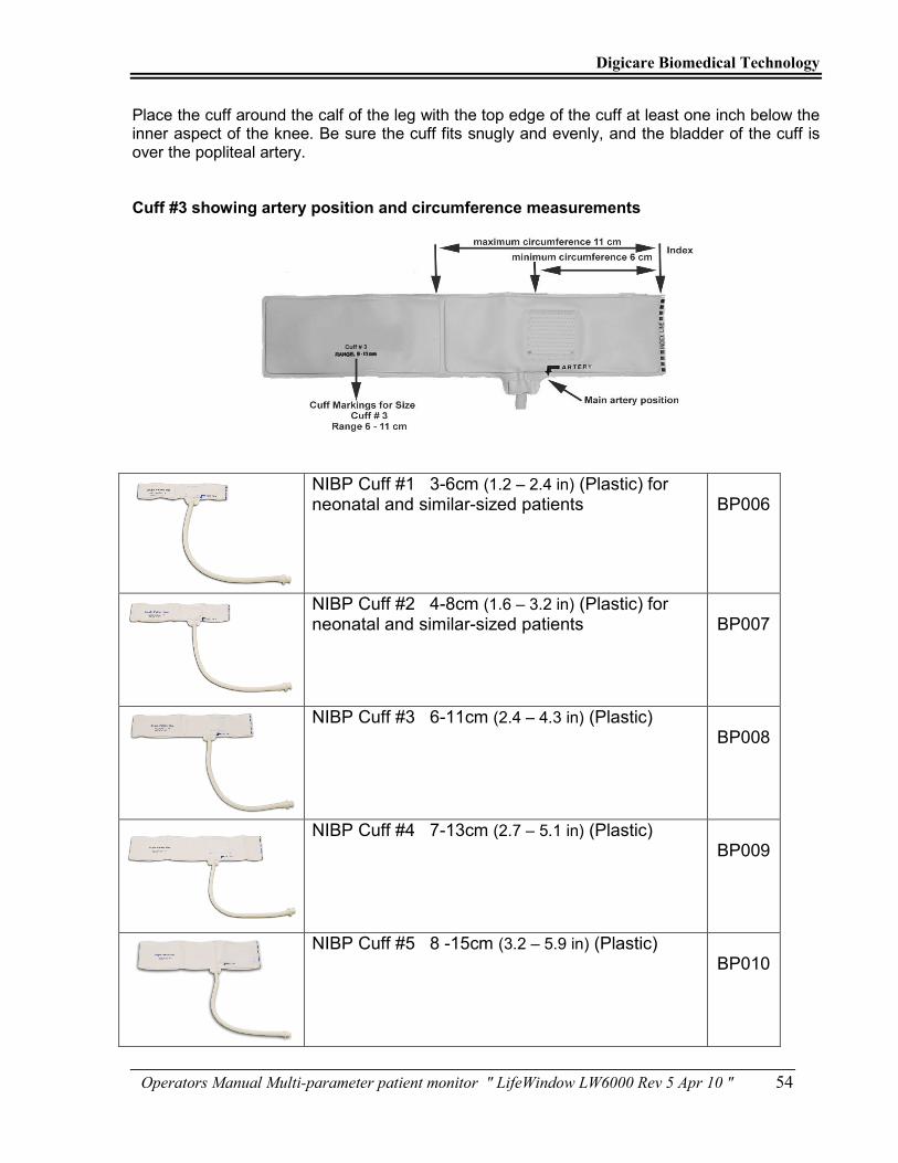
Digicare Biomedical Technology
Operators Manual Multi-parameter patient monitor " LifeWindow LW6000 Rev 5 Apr 10 " 54
Place the cuff around the calf of the leg with the top edge of the cuff at least one inch below the inner aspect of the knee. Be sure the cuff fits snugly and evenly, and the bladder of the cuff is over the popliteal artery. Cuff #3 showing artery position and circumference measurements
NIBP Cuff #1 3-6cm (1.2 – 2.4 in) (Plastic) for neonatal and similar-sized patients
BP006
NIBP Cuff #2 4-8cm (1.6 – 3.2 in) (Plastic) for neonatal and similar-sized patients
BP007
NIBP Cuff #3 6-11cm (2.4 – 4.3 in) (Plastic)
BP008
NIBP Cuff #4 7-13cm (2.7 – 5.1 in) (Plastic) BP009
NIBP Cuff #5 8 -15cm (3.2 – 5.9 in) (Plastic)
BP010

Digicare Biomedical Technology
Operators Manual Multi-parameter patient monitor " LifeWindow LW6000 Rev 5 Apr 10 " 55
NIBP Cuff #6 8 -13cm (3.2 – 5.1 in) (Cloth) BP005
NIBP Cuff #7 12 -19cm (4.7 – 7.5 in) (Cloth) BP003
NIBP Cuff #8 17-25cm (6.7 – 9.8 in) (Cloth) BP004
NIBP Cuff #9 28-40cm (11.0 – 15.7 in) (Cloth) BP002
NIBP Cuff #10 31-40cm (12.2 – 15.7 in) (Cloth) BP001
NIBP Cuff #11 45-65cm (17.7 – 25.6 in) (Cloth) BP000
NIBP Hose 10 Feet BP011
B. NON-INVASIVE BLOOD PRESSURE MONITORING
The NIBP monitor have three modes of operation: MANUAL, AUTOMATIC and STAT mode. At power-on the MANUAL mode is selected. To start a manual cycle press the dedicated NIBP START ( 5 ) pushbutton in the front panel. To stop the cycle and deflate the cuff, press the dedicated NIBP STOP ( 6 ) pushbutton in the front panel.

Digicare Biomedical Technology
Operators Manual Multi-parameter patient monitor " LifeWindow LW6000 Rev 5 Apr 10 " 56
1 - MANUAL MODE The MANUAL mode is a ONE CYCLE function. User can START a MANUAL cycle or STOP any type of cycle using the dedicated pushbuttons ( 5 ) and ( 6 ) in the front panel or in the NIBP menu.
2 - AUTOMATIC MODE • In the Automatic mode a cycle is repeated upon a selected period of time continuously. • In the NIBP menu select the AUTO mode and the cycle interval from 1 to 99 minutes. • Press the START button to start the NIBP determinations.
3 - STAT MODE • In the STAT mode a cycle is repeated many times as possible during a selected period of time (1 to 4min). • In the NIBP menu select the STAT mode and the cycle (1 to 4 min). Press the NIBP START button to start the STAT cycle. At the end of each cycle the SYSTOLIC, DIASTOLIC, MEAN and Pulse values are displayed and the time to STAT total cycle finish is decremented in display. 4 - ADULT / NEONATAL MODE SELECTION • The Mode (adult / neonatal) selection affects the NIBP operation. For Cuff sizes 1, 2, 3, 4 and 6 the NEONATAL mode should be selected. For Cuff sizes 5, 7 and 8, or larger, ADULT mode should be selected. 5 - NIBP DETERMINATION • On the NIBP menu, select the NIBP mode (Manual, Auto or Stat) and the cycle time. Press the Start button to Start a determination cycle. The pump will raise the pressure in the cuff to a default level for the Mode (Adult or Neonatal) selected. The pressure in the cuff deflates in a determined deflation rate Sensing the pressure oscillations in the cuff. If the Systolic pressure is equal or higher than the start pressure, the pump inflates again to increase the cuff pressure until it is higher than the systolic pressure. When the cuff pressure is lower than the diastolic pressure, at the end of the measurement cycle, the pump fully deflates the cuff and displays the Systolic, Diastolic and Mean Arterial Pressure values. The NIBP function is motion tolerant.
C. NIBP ALARM MESSAGES
“NIBP LOW SYS” – Indicates that Systolic value is lower than the selected SYSTOLIC LOWER LIMIT. “NIBP HIGH SYS” – Indicates that Systolic value is higher than the selected SYSTOLIC UPPER LIMIT. “NIBP LOW DIA” – Indicates that Diastolic value is lower than the selected DIASTOLIC LOWER LIMIT. “NIBP HIGH DIA” – Indicates that Diastolic value is higher than the selected DIASTOLIC UPPER LIMIT. “NIBP LOW MAP” – Indicates that MAP value is lower than the selected MAP LOWER LIMIT. “NIBP HIGH MAP” – Indicates that MAP value is higher than the selected MAP UPPER LIMIT.

Digicare Biomedical Technology
Operators Manual Multi-parameter patient monitor " LifeWindow LW6000 Rev 5 Apr 10 " 57
Air Leak – Indicates the pressure in the cuff is not reaching the necessary value. Check if the cuff is properly connected in the hose and in the NIBP receptacle in the Patient Panel. Check for air leaks in the cuff or hose. Excessive Motion – Indicates the motion artifact is affecting the NIBP determination. Time Too Long – Indicates the NIBP cycle is lasting too long for the NIBP determination and was aborted.
SECTION 9 - TEMPERATURE MONITORING
• The LifeWindow™ 6000 has two temperature channels and one Indicator to T1 – T2 temperature difference. The temperature probes are YSI 400 series compatible.
A. PATIENT CONNECTIONS
• To ensure conformance with all safety and performance specifications, use only the recommended accessories. These are available from DIGICARE.
Temperature rectal/esophageal probe – disposable
TP001
Temperature skin probe – disposable TP002
Temperature patient cable for disposable probe TP003
Temperature rectal/esophageal probe – reusable TP004
Temperature skin probe – reusable TP005
B. TEMPERATURE MONITORING
• Connect the temperature patient cable to receptacle (15 ) Temperature 1 or (16) Temperature 2. • In the Temperature menu select Temperature1, Temperature2 or T1-T2.

Digicare Biomedical Technology
Operators Manual Multi-parameter patient monitor " LifeWindow LW6000 Rev 5 Apr 10 " 58
• Select Temperature alarm High and Low limits. • Select Temperature measurement unit: °F or °C. • The temperature value is displayed when the probe temperature is in the 10 to 50°C (50 to 122 °F), range otherwise the temperature display is blanked. 1 - TEMPERATURE ALARM MESSAGES TEMP# SENSOR – Indicates the Temperature sensor is not connected to the unit or a sensor failure. TEMP# LOW – Indicates the Temperature value is lower than the selected Temperature Lower Limit. TEMP# HIGH – Indicates the Temperature value is higher than the selected Temperature Upper Limit.
SECTION 10 – INVASIVE PRESSURE MONITORING
• The LifeWindow™ 6000 can have 1, 2, 3 or 4 Invasive Pressure Channels installed. The following information apply for all channels. • The Invasive Pressure Channels are turned off in the factory default settings, to avoid alarms when not in use. • Turn-on Invasive Pressure Channel by touching in the IBPs menu, then touching Invasive Pressure 1, 2, 3 or 4 and touching IP# On. • The message “NO TRANSDUCER” is displayed until a Transducer is connected to the monitor.
A. PRESSURE TRANSDUCER To assure the performance specifications in this manual, use only the pressure transducer and accessories recommended by the manufacturer of this equipment.
IBP cable for reusable transducer IBP001
IBP reusable transducer Sensitivity: 50µV / V / mmHg
IBP002
IBP disposable dome for reusable transducer IBP003
IBP monitoring kit for reusable transducer (Includes lines, stopcocks and disposable dome)
IBP004

Digicare Biomedical Technology
Operators Manual Multi-parameter patient monitor " LifeWindow LW6000 Rev 5 Apr 10 " 59
IBP IV Pole bracket for reusable transducer IBP008
IBP Dual Transducer bracket for reusable transducer IBP009
IBP cable for disposable transducer IBP005
IBP disposable transducer with line (monitoring kit) Sensitivity: 50µV / V / mmHg
IBP006
IBP disposable transducer without line Sensitivity: 50µV / V / mmHg
IBP007
B. PRESSURE TRANSDUCER CONNECTION • Connect the pressure transducer cable to connector IP1 (19),IP2 (20), IP3 (21) or IP4 (23). • Connect the catheter to pressure transducer. • Install the flow system and maintain the entire system with liquid. • Hold the transducer at the heart level (axial line). • Following is a generic transducer line assembly example.

Digicare Biomedical Technology
Operators Manual Multi-parameter patient monitor " LifeWindow LW6000 Rev 5 Apr 10 " 60
C. IP SCALE AND LABEL • Touch in the IBPs menu or in the IBP channel Indicators area to open the IP menu screen. • The pre-configured default scale for the Invasive Pressure waveform is 0 to +180 mmHg. To change the scale touch in the IP# Scales drop down menu and touch the desired IP scale. The Scale options are: -30 to +30 mmHg 0 to +30 mmHg 0 to +60 mmHg 0 to +90 mmHg 0 to +120 mmHg 0 to +180 mmHg 0 to +240 mmHg 0 to +300 mmHg +30 to +90 mmHg +60 to +120 mmHg +90 to +150 mmHg +120 to +180 mmHg +150 to +210 mmHg +180 to +240 mmHg +210 to +270 mmHg +240 to +300 mmHg • The Label displayed in the right side of the Invasive Pressure waveform can be selected to reflect the site where the Invasive Pressure is being measured. • The pre-configured default Label is IP1, IP2, IP3 and IP4 for Invasive Pressure 1, 2, 3 and 4 respectively. • To change the IBP Label, touch in the IBP# Label drop down menu and select the desired Label. The Labels are color coded. IP1 - Blue - Invasive Pressure Channel 1

Digicare Biomedical Technology
Operators Manual Multi-parameter patient monitor " LifeWindow LW6000 Rev 5 Apr 10 " 61
IP2 - Blue - Invasive Pressure Channel 2 IP3 - Blue - Invasive Pressure Channel 3 IP4 - Blue - Invasive Pressure Channel 4 ART - Red - Arterial Pressure CVP - Cyan - Central Venous Pressure PA - Yellow - Pulmonary Artery LAP - Green - Left Atrium Pressure ICP - Gray - Intracranial Pressure
D. TRIGGER SOURCE • The LifeWindow™ 6000 determine the Systolic (maximum amplitude) and Diastolic (minimum amplitude) values based on a period of time generated by Trigger Pulses. The default trigger pulses are generated by the IP board based on the systole slope of the Invasive Pressure waveform. • For each systole detected, the IP board generates one Trigger Pulse and the Invasive Pressure Pulse Indicator is displayed. • The CVP and other low frequency Invasive Pressure waveforms do not generate Trigger Pulse, so the unit can not determine the Systolic and Diastolic values. • Using the ECG trigger pulses the LifeWindow™ 6000 is capable to determine the Systolic and Diastolic values in these cases. • To use the ECG as the source for triggering the IP function, touch in the IPBs menu and select in the Trigger Source drop down menu to ECG. • The LifeWindow™ 6000 using the ECG as trigger source for Invasive Pressure determination will display the Systolic and Diastolic values of any Invasive Pressure waveform, as long as the ECG is being detected normally and Heart Rate is being displayed. • Note: When using the ECG as trigger source for IP, the Invasive Pressure Pulse Indicator is NOT displayed
E. PULSATILE / STATIC MODE
• The LifeWindow™ 6000 Invasive Pressure function has two main modes of operation, Static Mode and Pulsatile Mode. The Pulsatile mode is pre-configured as default. • In the Pulsatile mode, the Invasive Pressure Indicators and Alarms are set for Systolic, Diastolic and Mean Pressure. In this mode, the IP NO PULSE alarm will be displayed if the Invasive Pressure waveform is not generating Trigger Pulses. Note: If the ECG is being used to trigger the IP determination, the IP NO PULSE alarm will NOT be displayed. • In the Static mode , the Invasive Pressure Indicators and Alarms are set only for Static Pressure. The IP NO PULSE alarm is disabled in this mode. • To change from Pulsatile to Static Mode, touch the IBP menu and select in the drop down menu the Static mode.
F. TRANSDUCER ZERO • The message “ZERO TRANSDUCER” is displayed until a zero calibration procedure is executed. • Open the TRANSDUCER input to the air (Local Atmospheric Pressure). Touch in the IBP menu and touch in the Invasive Pressure #. Touch the Zero Xducer button. • If the transducer Zero calibration procedure was successful, the Invasive Pressure waveform shall be displayed at ZERO baseline and the Invasive Pressure readings are displayed. • If the transducer Zero calibration procedure was NOT successful, the “IP# ERROR ZEROING” message is displayed on screen. • The invasive pressure range to execute the Zero Calibration procedure is from 150 mmHg to + 150 mmHg.

Digicare Biomedical Technology
Operators Manual Multi-parameter patient monitor " LifeWindow LW6000 Rev 5 Apr 10 " 62
G. INVASIVE PRESSURE ALARM LIMITS • The LifeWindow™ 6000 Invasive Pressure alarm limits default and range is: Systolic Upper Limit: 160 mmHg Range: 0 to 300 mmHg Systolic Lower Limit: 60 mmHg Range: 0 to 300 mmHg Diastolic Upper Limit: 100 mmHg Range: 0 to 300 mmHg Diastolic Lower Limit: 60 mmHg Range: 0 to 300 mmHg Mean Upper Limit: 120 mmHg Range: 0 to 300 mmHg Mean Lower Limit: 60 mmHg Range: 0 to 300 mmHg Static Upper Limit: 120 mmHg Range: 0 to 300 mmHg Static Lower Limit: 60 mmHg Range: 0 to 300 mmHg • In the IP# menu, select the Invasive Pressure Systolic, Diastolic and Mean Upper and Lower alarm limits. To return to the factory DEFAULT alarm limits, go to the SYSTEM menu and press the Load Factory Default Settings.
H. INVASIVE PRESSURE ALARM MESSAGES IP# NO TRANSDUCER – Indicates the Invasive Pressure transducer is not connected to the unit or a transducer failure. IP# ZERO TRANSDUCER – Indicates the need to perform a transducer Zero Calibration procedure. IP# ERROR ZEROING – Indicates error in transducer Zero Calibration procedure. IP# LOW SYSTOLIC – Indicates the Systolic value is lower than the selected Systolic Lower Limit. IP# HIGH SYSTOLIC – Indicates that Systolic value is higher than the selected Systolic Upper Limit. IP# LOW DIASTOLIC – Indicates the Diastolic value is lower than the selected Diastolic Lower Limit. IP# HIGH DIASTOLIC – Indicates the Diastolic value is higher than the selected Diastolic Upper Limit. IP# LOW MEAN – Indicates that Mean value is lower than the selected Mean Lower Limit. IP# HIGH MEAN – Indicates that Mean value is higher than the selected Mean Upper Limit. IP# LOW STATIC – Indicates that Mean value is lower than the selected Mean Lower Limit. IP# HIGH STATIC – Indicates that Mean value is higher than the selected Mean Upper Limit.
SECTION 11 – FRACTION OF INSPIRED OXIGEN - FIO2
A. PRINCIPLE OF OPERATION
• The LifeWindow™ 6000 provides fast and accurate oxygen monitoring. It is designed to monitor up to 100% oxygen concentration in medical gas mixtures. It is capable of rapidly measuring the oxygen content of an atmosphere or environment. • The LifeWindow™ 6000 is intended to continuously measure and display the Concentration of oxygen in a gas mixtures used in medical applications such as Anesthesia and Respiratory therapy.

Digicare Biomedical Technology
Operators Manual Multi-parameter patient monitor " LifeWindow LW6000 Rev 5 Apr 10 " 63
B. PATIENT CONNECTIONS
• The LifeWindow™ 6000 uses one polarographyc oxygen sensor. Attached to the sensor is a removable plastic diverter. This diverter is used to facilitate the transport of gas mixtures through the sensor. The diverter, packaged separately when shipped, is necessary when the tee adapter is used to sample gas flowing through a tube. The diverter is not necessary and should not be used when the sensor is placed directly in a chamber, or when the sensor is used in confined volume monitoring, such as incubators and inhalation tents. 1 - SENSOR INSTALLATION OR REPLACEMENT • Remove the new sensor from its protective bag. Inspect the sensor for damage or electrolyte leakage. If the sensor is damaged, obtain a replacement. Do not use the defective sensor as it may damage the unit. • WARNING: The sensor electrolyte is caustic. Do not let it come in contact with skin. If it does, flush affected area with water. Do not attempt to open or repair the sensor.
• WARNING: The sensor also contains lead. Leaking or exhausted sensors should be handled and disposed of in accordance with local regulations.
• Connect one end of the FIO2 patient cable into the jack receptacle on the back end of sensor. • Connect the other end of the cable into the receptacle (17) located on the patient connections panel of the unit. Mounting the Sensor in the Tee Adapter
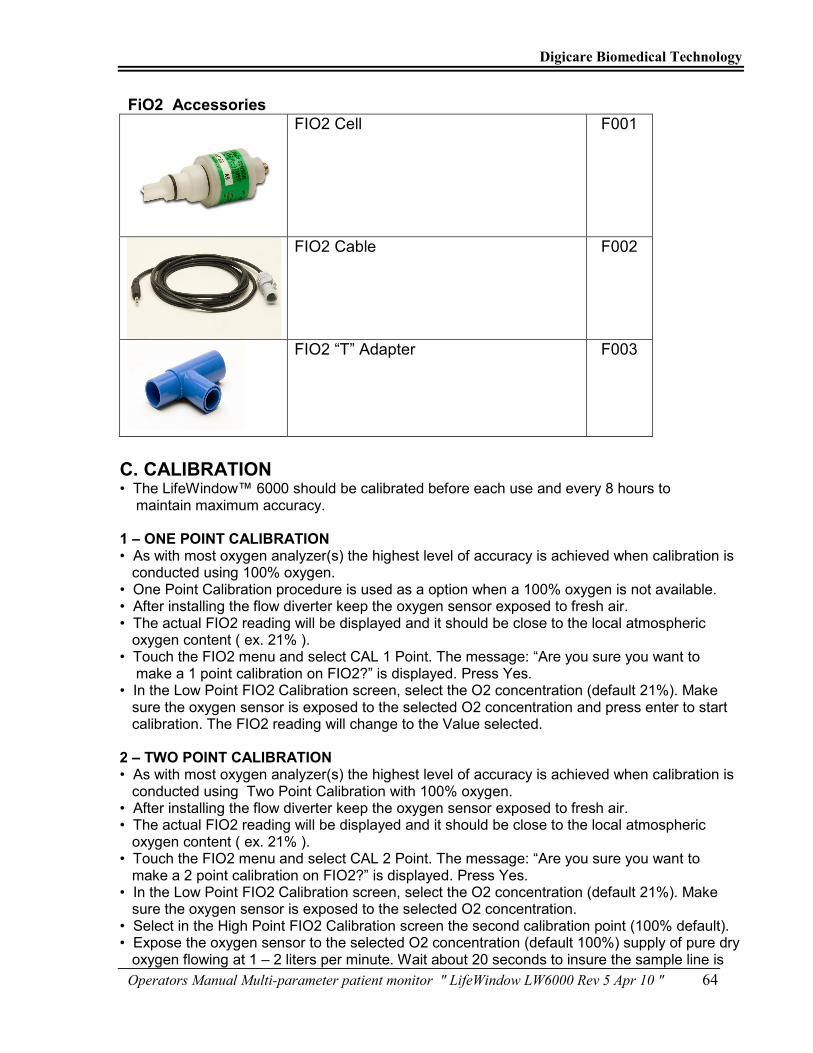
Digicare Biomedical Technology
Operators Manual Multi-parameter patient monitor " LifeWindow LW6000 Rev 5 Apr 10 " 64
FiO2 Accessories
FIO2 Cell F001
FIO2 Cable F002
FIO2 “T” Adapter F003
C. CALIBRATION
• The LifeWindow™ 6000 should be calibrated before each use and every 8 hours to maintain maximum accuracy.
1 – ONE POINT CALIBRATION • As with most oxygen analyzer(s) the highest level of accuracy is achieved when calibration is conducted using 100% oxygen. • One Point Calibration procedure is used as a option when a 100% oxygen is not available. • After installing the flow diverter keep the oxygen sensor exposed to fresh air. • The actual FIO2 reading will be displayed and it should be close to the local atmospheric oxygen content ( ex. 21% ). • Touch the FIO2 menu and select CAL 1 Point. The message: “Are you sure you want to make a 1 point calibration on FIO2?” is displayed. Press Yes. • In the Low Point FIO2 Calibration screen, select the O2 concentration (default 21%). Make sure the oxygen sensor is exposed to the selected O2 concentration and press enter to start calibration. The FIO2 reading will change to the Value selected. 2 – TWO POINT CALIBRATION • As with most oxygen analyzer(s) the highest level of accuracy is achieved when calibration is conducted using Two Point Calibration with 100% oxygen. • After installing the flow diverter keep the oxygen sensor exposed to fresh air. • The actual FIO2 reading will be displayed and it should be close to the local atmospheric oxygen content ( ex. 21% ). • Touch the FIO2 menu and select CAL 2 Point. The message: “Are you sure you want to make a 2 point calibration on FIO2?” is displayed. Press Yes. • In the Low Point FIO2 Calibration screen, select the O2 concentration (default 21%). Make sure the oxygen sensor is exposed to the selected O2 concentration. • Select in the High Point FIO2 Calibration screen the second calibration point (100% default). • Expose the oxygen sensor to the selected O2 concentration (default 100%) supply of pure dry oxygen flowing at 1 – 2 liters per minute. Wait about 20 seconds to insure the sample line is

Digicare Biomedical Technology
Operators Manual Multi-parameter patient monitor " LifeWindow LW6000 Rev 5 Apr 10 " 65
completely purged with the calibration gas and press Enter to calibrate. • Remove the sensor from the oxygen supply and confirm the FIO2 indicator reads less than 22% in room air. • It is important to perform the calibration carefully and thoroughly, using calibration gases that are free from contaminates. Wait for a stable reading before locking in calibration point. 3 – DEFAULT CALIBRATION • The Default Calibration procedure returns the FIO2 function calibration to factory default calibration. • To return the FIO2 function to the factory default calibration touch the FIO2 menu and touch the Cal Default button.
D. FIO2 MONITORING • The LifeWindow™ 6000 can be used to measure a gas mixture for oxygen in two basic modes: • In the inhalation side of breathing circuit ahead of humidifiers and medicating devices or other instances where gases are flowing to a patient in breathing circuits. When monitoring oxygen in breathing circuits, the flow diverter must be used. • In confined volumes such as tents and hoods. In these applications the flow diverter must be removed from the sensor so that it does not interfere with the rapid exchange of gases to and from the sensing surface of the sensor. • CAUTION: Check the breathing circuit for leaks. Be certain that the circuit downstream of the sensor does not produce any backpressure or restriction to flow. Errors in readings will result if this is not followed. • Never install the sensor in a location that will expose the sensor to patients exhaled breath or secretrions unless you intend to dispose of the sensor and flow adapter after use. 1 - GAS SAMPLING 1.1 - HUMIDITY • Humidity does not directly affect the accuracy of the sensor's measurement. However, when a nebulizer or other device is used to increase moisture levels in gas mixtures, the moisture actually dilutes the mixture. This dilution effect decreases the oxygen concentration. The LifeWindow™ 6000 oxygen monitor accurately measures decreases in the oxygen concentration due to the dilution effects of moisture added to gas mixtures. • As with all oxygen sensors, excessive condensation on the sensing surface will block the diffusion of oxygen to the sensor, rendering it inoperative. We recommend installing the sensor on the dry side of the breathing circuit at all times.
1.2 - TEMPERATURE • The oxygen sensor adjusts for ambient temperature changes in the range of 0–40°C (32– 106°F). Since the thermistor that compensates for these changes is located in the rear of the sensor assembly, it is important that gas mixtures, flowing over the front of the sensor, be at room temperature. Reading errors may occur if hot gases from a heated humidifier are directed past a sensor teed into a breathing circuit. 1.3 - PRESSURE • Virtually all gas sensors and monitors measure the partial pressure, not the percentage, of the gas that they sense. The only time that these instruments can accurately read percentages is when the total pressure does not vary over time between calibrations and use. For this reason it is important to calibrate the LifeWindow™ 6000 oxygen sensor at regular intervals. It is recommended that the unit be calibrated prior to each use or every 8 hours.

Digicare Biomedical Technology
Operators Manual Multi-parameter patient monitor " LifeWindow LW6000 Rev 5 Apr 10 " 66
• When the sensor is connected to a ventilator circuit, the alternating “breathing” pressure cycles generated by the ventilator will be sensed as an increase in the oxygen percentage. In reality, the percentage of oxygen is not changing; it is the total pressure that is increasing producing a corresponding increase in the partial pressure of oxygen. A hundred centimeter of water pressure pulse will produce a 0.11 atmosphere, or an 11% increase in the total and therefore partial pressure of oxygen. The reading will rise proportionally less for smaller pressures. 1.4 - ANESTHETIC GASES • When using the LifeWindow™ 6000 oxygen sensor in the presence of anesthetic gases such as Isoflurane, the oxygen reading may fall (see Table below). The magnitude of this error will depend upon the level of oxygen and the duration of exposure. Halothane 4% < 1.5% O2 Enflurane 5% < 1.5% O2 Isoflurane 5% < 1.5% O2 Sevoflurane 5% < 1.5% O2 Desflurane 15% < 1.5% O2 Note: Errors are approximate and may vary based on exposure times and concentrations. These performances meet or exceed the requirements of ISO 7767: 1997 (E). Caution: The LifeWindow™ 6000 should not be used in the presence of flammable anesthetics such as diethyl ether or cyclopropane. 2 - FIO2 ALARM LIMITS • The LifeWindow™ 6000 FIO2 alarm limits default and range is: FIO2 Upper Limit: OFF Range: 5 to 100% FIO2 Lower Limit: 20% Range: 0 to 95% • In the FIO2 menu, select the Upper and Lower alarm limits. To return to the factory DEFAULT alarm limits, go to the SYSTEM menu and press the Load Factory Default Settings.
3 - FIO2 ALARM MESSAGES FIO2 HIGH – Indicates the FIO2 reading is higher than the Upper Limit set. FIO2 LOW – Indicates the FIO2 reading is lower than the Lower Limit set.
Digicare Biomedical Technology
Operators Manual Multi-parameter patient monitor " LifeWindow LW6000 Rev 5 Apr 10 " 67
SECTION 12 – TECHNICAL SPECIFICATIONS
A. MECHANICAL DESCRIPTION Size : 13.6 x 9.0 x 8 inches (280 x 140 x 203 mm) Weight : 18lb (8Kg) Color : White
B. POWER REQUIREMENTS AC voltage Input : 100-240 VAC / 50-60 Hz max 80W Universal Power Input
C. ECG Lead Selection : I, II, III, avR, avL, avF, Vx (Standard 5 lead configuration) Waveforms : Display simultaneously 3 Lead, 6Lead, 12 Lead (I, II, III, aVL, aVR, aVF,V1- V6)
Input Isolation : Isolated from Ground related circuits by ≥ 4KV rms / 5.5 KV peak Frequency Response Diagnostic: 0.05 - 100Hz Monitoring: 0.5 – 35Hz Surgery: 1 – 15Hz
Leakage Current : < 10 µA at 120 to 240 Vac 50 / 60 Hz Defibrillator & ESU Protection : Max. 360J Test Signal : 1 mV square wave Heart Rate Range : 15 to 300 BPM
Accuracy : ± 1% Resolution : 1 BPM Sensibility Large Mode : 0.3 mV peak Small Mode : 0.2 mV peak Pacemaker Rejection Amplitude : 2mV to 700 mV, Duration : 0.1 to 2 ms Sweep Speed : 6.25, 12.5, 25, 50 mm/sec Lead Fault Alarm : Audible and visual Input : 3 / 5 Lead ECG patient cable Gain Selection : Auto and Manual by operator QRS Indicator : Adjustable audible, visual Patient Cable : 6 pin AAMI standard
CMRR : ≥ 90 dB
Input impedance : ≥ 5 MΩ at 10 Hz with patient cable
Electrode Offset potential : ± 0.3 V
D. SpO2 - PULSE OXIMETER SpO2 Range : 0 to 100% adult/pediatric/neonate
SpO2 Accuracy : ± 2% (70 - 100%), ± 3% (50 - 69%) unspecified (0 - 49%) SpO2 Resolution : 1% SpO2 averaging : 8 seconds Pulse Rate Range : 30 to 450 BPM Pulse Rate Accuracy : ± 2% Pulse Rate Resolution : 1 BPM Pulse Rate Averaging : 16 pulses Sensor Types : Finger Probe and Wrap

Digicare Biomedical Technology
Operators Manual Multi-parameter patient monitor " LifeWindow LW6000 Rev 5 Apr 10 " 68
E. NON-INVASIVE BLOOD PRESSURE Method : Automatic Oscillometric Measured Parameters : Systolic, Diastolic, Mean Arterial Pressure, Pulse. Scale : mmHg (Kpascal optional) Operating Modes : Manual, Automatic, Stat Auto Repeat Cycles : 1 - 120 minutes Stat Cycle : 1 - 4 minutes NIBP Range : 10 – 270 mmHg Systolic Range : Adult 40 - 270 mmHg : Neonatal 40 - 270 mmHg Diastolic Range : Adult 10 - 210 mmHg : Neonatal 10 - 210 mmHg Mean Range : Adult 20 - 230 mmHg : Neonatal 20 - 230 mmHg Absolute Maximum Inflation Pressure : Adult 300 mmHg : Neonatal 300 mmHg Inflation Time : Adult 15 sec : Neonatal 4.5 sec Measurement Time : Adult 30 seconds typical 100 seconds maximum : Neonatal 30 seconds typical 80 seconds maximum Pressure Display Accuracy : ± 3 mmHg Pressure Resolution : 1mmHg BP Pulse Rate Accuracy : ± 3 BPM 40 - 200 BPM : ± 5 BPM 200 - 255 BPM
F. TEMPERATURE Range : 30 - 122
0F (-1 to 50
0C)
Probe : YSI - 400 Compatible, Skin or Rectal / esophageal and disposable Scale : Degrees C (Fahrenheit optional)
Accuracy : ± 0.1 °F from 77 to 103 °F (: ± 0.1 0C from 25 – 45
0C)
Resolution : 0.1 °F ( 0.1 0C )
G. CO2 Transducer Type : Mainstream Principle of Operation : Non-dispersive infrared (NDIR) single beam optics, dual wavelength, no moving parts. Initialization Time : Capnogram displayed in less than 15 seconds, CO2 Measurement Range : 0 to 150 mmHg CO2 Rise Time : Less than 60 ms - reusable or single patient use CO2 Resolution : 0.1 mmHg 0 to 69 mmHg : 0.25 mmHg 70 to 150 mmHg CO2 Accuracy : 0 - 40 mmHg ± 2 mmHg :41 - 70 mmHg ± 5% of reading :71 - 100 mmHg ± 8% of reading : 101 - 150 mmHg ± 10% of reading CO2 Short Term Drift : shall not exceed 0.8 mmHg maximum. CO2 Long Term Drift : Accuracy specification will be maintained over a 120 hour period. CO2 Noise RMS : noise of the sensor shall be less than or equal to 0.25 mmHg at 7.5% CO2 Sampling Rate :100 Hz Respiration Rate Range : 0 to 150 breaths per minute (BPM) Respiration Rate Accuracy : ± 1 breath

Digicare Biomedical Technology
Operators Manual Multi-parameter patient monitor " LifeWindow LW6000 Rev 5 Apr 10 " 69
Calibration : No routine user calibration required. An airway adapter zero is required when changing to a different style of airway adapter. Compensations for : Expired O2, balance gas (N2, N2O, He) and anesthetic agents Weight : 25 grams – Sensor only Size : 33 mm high x 43 mm wide x 23 mm deep 3 meter cable standard Temperature and Humidity Operating : 0 to 45°C, 10 to 90% RH, non-condensing Mode of Sampling : Sidestream Principle of Operation : Non-dispersive infrared (NDIR) single beam optics, dual wavelength, no moving parts. Initialization Time : less than 20 seconds CO2 Measurement Range : 0 to 150 mmHg CO2 Response Time : <3 seconds - includes transport time and rise time CO2 Resolution : 0.1 mmHg 0 to 69 mmHg : 0.25 mmHg 70 to 150 mmHg CO2 Accuracy : 0 - 40 mmHg ± 2 mmHg : 41 - 70 mmHg ± 5% of reading :71 - 100 mmHg ± 8% of reading :101 - 150 mmHg ± 10% of reading : Above 80 breath per minute ± 12% of reading CO2 Short Term Drift : shall not exceed 0.8 mmHg maximum. CO2 Long Term Drift : Accuracy specification will be maintained over a 120 hour period. CO2 Noise RMS : less than or equal to 0.25 mmHg Sampling Rate :100 Hz Respiration Rate Range : 2 to 150 breaths per minute (BPM) Respiration Rate Accuracy : ± 1 breath Calibration : No routine user calibration required. Inspired CO2 Measurement Range : 3 to 50 mmHg Compensations for :Expired O2, Balance gas (N2, N2O, He) and Anesthetic Agents Module weight : less than 9.6 oz (272.16 g) Module Size : < 2.6" wide x 1.5" high x 3.5" deep [< 66.0 x 38.1 x 88.9 mm] Cable length :22 inches (55.88 cm) Temperature and Humidity Operating : 0 to 40°C, 10 to 90% RH, non-condensing
H. INVASIVE PRESSURE IBP Range : -40 to 360 mmHg Frequency Response : DC to 12 Hz
Input Impedance : 500 KΩ
Transducer sensitivity : 5µV / V / mmHg Excitation voltage : + 5 VDC
Zero : Auto push-button ± 150 mmHg
Drift : 0.1mmHg/°C
Accuracy : ± 2% F.S.
Isolation : Isolated from ground related circuits by ≥ 4KV RMS, 5.5KV peak
I. FIO2 Range : 0-100% oxygen Accuracy : +2% of full scale (at constant temperature

Digicare Biomedical Technology
Operators Manual Multi-parameter patient monitor " LifeWindow LW6000 Rev 5 Apr 10 " 70
and pressure) Response Time : 90% in less than 8 seconds at 25 °C Sensor Expected Life : 36 months in air. (10 months when continuously exposed to 100% oxygen)
J. BIOIMPEDANCE RESPIRATION Method : Impedance between R-F(RA-LL) Measuring Impedance Range : 0.3~3.0Ω
Base line Impedance Range : 200 – 4.5 KΩ(include the impedance of ECG Lead wire)
Bandwidth : 0.2 ~ 2.5 Hz(-3dB) Resp. Rate
Measuring range : 0 to 200 rpm (breaths per minute) Resolution : 1 rpm
Accuracy :±2 rpm
K. DISPLAY Type : 12.1” TFT – Active Matrix Color Flat Panel Display Effective Display Area : 246.0(H) x 184.5(V) mm.
L. ENVIRONMENT SPECIFICATIONS Temperature : Operating 5°C to 45°C : Transport and Storage 5°C to 55°C Relative Humidity : Operating 30 - 75% (Non-Condensing) : Transport and Storage 30 - 75% (Non-Condensing) Atmospheric Pressure : Operating 700 – 1060hpa : Transport and Storage 700 – 1060hpa
M. TRENDS GRAPHICAL TRENDS: Present all physiologic variables trend waveforms for a passed period of time selected by the operator: 15 min, 1, 4, 12, 24, 48 and 72 hours. TABULAR TRENDS: Present all physiologic variables trend in tabular data format since the patient was admitted until the present time.
N. AUXILIARY OUTPUT Pin 1 - Impedance Respiration waveform. Pin 2 - ECGx1000 analog waveform. Pin 3 - ECG Trigger Pulses: +12V positive pulses to defibrillator synchronism. Pin 4 - Impedance Respiration Trigger Pulses. Pin 5 - Invasive Pressure 1 analog waveform. Pin 6 - Invasive Pressure 2 analog waveform. Pin 7 - Invasive Pressure 3 analog waveform. Pin 8 – Invasive Pressure 4 analog waveform. Pin 9, Pin10, Pin11, Pin12 - GND Pin13 - RS232 – RXD optional depends on the model. Pin14 - RS232 – TXD optional depends on the model. Pin15 - RS232 – GND optional depends on the model. DB15
8 7 6 5 3 2 1
15
4
1 4 1 3 1 2 1 1 1 0 9

Digicare Biomedical Technology
Operators Manual Multi-parameter patient monitor " LifeWindow LW6000 Rev 5 Apr 10 " 71
SECTION 13 – MAINTENANCE
A. THE MONITOR
When necessary, clean the exterior surfaces of the monitor with a cloth or swab dampened with warm and a mild detergent solution. Do not allow fluids to enter the interior of the instrument.
WARNING: Electrical shock and flammability hazard - always turn the monitor off and disconnect it from AC mains power before cleaning.
CAUTION: Do not autoclave or pressure sterilize this monitor. Do not stack or immerse this monitor in any liquid. Do not gas sterilize this monitor.
Do not touch, or rub the display panel with abrasive cleaning compounds, instruments, brushes, rough surfaced materials or make contact with anything that can scratch the panel.
B. PROBES
• The probes are the only surfaces of this monitor that come in contact with the patient. Clean the probes after each patient use. • Clean the monitor’s probes with a commercial cleaning solution before attaching a new patient. Probes should be cleaned until signs of wear or splitting occur. At this time a new probe is required. • If disinfection is required, wipe the surfaces with Isopropyl alcohol or cider and use a water rinse. When sterilization is required, use ethylene oxide and be sure to follow hospital procedures. • Inspect the probe for wear or splitting after every disinfecting/sterilization process is complete. • If wearing or splitting of the probe is found upon visual inspection, a new probe should be used
1 - MAINFLOW™ CO2 MAINSTREAM SENSOR • Use a cloth dampened with isopropyl alcohol 70%, a 10% aqueous solution of sodium hypochlorite (bleach), disinfectant spray cleaner such as Steris Coverage® Spray HB, ammonia, or mild soap. • Wipe down with a clean water-dampened cloth to rinse and dry before use. Make certain that the sensor windows are clean and dry before reuse.
2 - MAINFLOW™ CO2 MAINSTREAM AIRWAY ADAPTERS CLEANING REUSABLE ADAPTERS • Clean by rinsing in a warm soapy solution followed by soaking in a liquid disinfectant such as isopropyl alcohol 70%, a 10% aqueous solution of sodium hypochlorite (bleach), a gluteraldehyde 2.4% solution such as Cidex®, Steris System 1® or ammonia. It should then be rinsed out with sterile water and dried. • May be disinfected using the methods listed below: • Steam Autoclave – Large adapters only • Immerse and soak in Cidex® or equivalent 2.4 glutaraldehyde solution for a 10 hour soak. • Immerse and soak in Perasafe® or equivalent peracetic acid .26% solution for 10 minutes. • Cidex® OPA - follow the manufacturer’s instructions for use. • Before reusing the adapter, ensure the windows are dry and residue free and that the adapter has not been damaged during handling or the cleaning/disinfecting process.

Digicare Biomedical Technology
Operators Manual Multi-parameter patient monitor " LifeWindow LW6000 Rev 5 Apr 10 " 72
DISPOSABLE ADAPTERS • Treat all single patient use airway adapters in accordance with institutional protocol for single patient use items. • DO NOT insert any object, such as a brush, into the MainFlow™ CO2 mainstream Sensor airway adapter. Irreparable damage may occur to the CO2 windows. 3 - MICROFLOW™ CO2 SIDESTREAM MODULE CASE, CABLE AND CONNECTOR • Use a cloth dampened with isopropyl alcohol 70%, a 10% aqueous solution of sodium hypochlorite (bleach), a 2% gluteraldehyde solution, ammonia, mild soap or disinfectant spray cleaner such as Steris Coverage® Spray HB. • Wipe down with a clean water-dampened cloth to rinse and dry before use. Make certain that the sensor windows are clean and dry before reuse.
4 - SIDESTREAM AIRWAY ADAPTERS AND SAMPLE LINE • MicroFlow™ CO2 sidestream on-airway adapters and sidestream sample lines are single patient use. Treat in accordance with hospital protocols for handling single patient use devices.
5 – OXYGEN SENSOR, DIVERTER AND TEE ADAPTER • The external surfaces of the oxygen sensor and cable may be cleaned by wiping with a cloth moistened with a mild detergent solution. • The diverter and tee adapter may be disinfected by washing them with isopropyl alcohol or Cidex. The parts must be thoroughly dry before they are used.
C. PATIENT CABLES
• Do not autoclave the patient cables. • Wipe the cables using soap and water or alcohol. Never submerge the cables in any liquid or allow liquids to enter the electrical connections.
D. BATTERY
• The LifeWindow 6000 series monitor has two batteries 12V / 2.9AH SEALED ACID. To ensure long life and proper operation follow the instructions: • Use the 6000 powered by its internal batteries at least once time a month until the “LO BATTERY” message appears on display. • If the 6000 is stored for long period without use, connect the 6000 to the AC line to recharge the batteries for at least 18 hours once for each month period. • In case you need to replace the batteries refer to the service manual.

Digicare Biomedical Technology
Operators Manual Multi-parameter patient monitor " LifeWindow LW6000 Rev 5 Apr 10 " 73
WARRANTY TERMS & CONDITIONS
DIGICARE BIOMEDICAL TECHNOLOGY, INC. covers all of their monitors with a 1 year warranty: Monitors 1 year parts and labor Accessories: 90 days on accessories only DIGICARE BIOMEDICAL TECHNOLOGY, INC. will provide the necessary parts and labor to maintain the monitor (s) listed on the Warranty Certificate in a usable condition during the covered period. DIGICARE BIOMEDICAL TECHNOLOGY, INC. will, at its option, repair or replace any product which proves to be defective during the warranty period, if returned to the factory with prior authorization, transportation prepaid. Not covered by this agreement are repairs necessitated by any of the following conditions: 1 - Inadequate power or power failure. 2 - Neglect, abuse or misuse of equipment. 3 - Servicing of equipment by person’s other than DIGICARE INC. 4 - Any unit opened or tampered with, without prior authorization. When returning a monitor for extended warranty repair, you must first contact DIGICARE BIOMEDICAL TECHNOLOGY, INC. to receive a Returned Goods Authorization Number (RGA #) that is to be clearly marked on top of the shipping carton. Please make sure that your company name, shipping address, area code and telephone number and person to contact is located in and/or on the box. ANY UNIT THAT IS RETURNED TO THE FACTORY WITHOUT AN RGA# WILL BE REFUSED.
Model # __________________________ Serial # _____________________ Dealer Name: ________________________________________________ Date Equip. Purch.: ________________________ Expiration Date: ___________________
DIGICARE BIOMEDICAL TECHNOLOGY INC. 107 Commerce Road
Boynton Beach, FL 33426
FOR YOUR RECORDS


![CTK-6000/WK-6500/CTK-7000/WK-7500/AT- 3/AT-5 MIDI ... · Send Sent when the DSP parameter setting is configured. Receive Receipt changes the value of DSP Parameter 7 [1 to 8] (7-bit](https://img.pdfslide.net/doc/110x75/5f42127c508f3639046bb38e/ctk-6000wk-6500ctk-7000wk-7500at-3at-5-midi-send-sent-when-the-dsp-parameter.jpg)