Embed Size (px)
Citation preview
TABLE OF CONTENTS Page 1
TABLE OF CONTENTS DIVISION 21 - FIRE SUPPRESSION 21 1300 FIRE SUPPRESSION SPRINKLERS DIVISION 22 - PLUMBING 22 0553 IDENTIFICATION FOR PLUMBING PIPING AND EQUIPMENT 22 0716 PLUMBING EQUIPMENT INSULATION 22 0719 PLUMBING PIPING INSULATION 22 1005 PLUMBING PIPING 22 1006 PLUMBING PIPING SPECIALTIES 22 3000 PLUMBING EQUIPMENT 22 4000 PLUMBING FIXTURES DIVISION 23 - HEATING, VENTILATING, AND AIR-CONDITIONING (HVAC)
23 0513 COMMON MOTOR REQUIREMENTS FOR HVAC EQUIPMENT 23 0553 IDENTIFICATION FOR HVAC PIPING AND EQUIPMENT 23 0713 DUCT INSULATION 23 2300 REFRIGERANT PIPING 23 3100 HVAC DUCTS AND CASINGS 23 3300 AIR DUCT ACCESSORIES 23 3416 CENTRIFUGAL HVAC FANS 23 3700 AIR OUTLETS AND INLETS 23 8127 SMALL SPLIT-SYSTEM HEATING AND COOLING DIVISION 26 - ELECTRICAL 26 0526 GROUNDING AND BONDING FOR ELECTRICAL SYSTEMS 26 0529 HANGERS AND SUPPORTS FOR ELECTRICAL SYSTEMS 26 0534 CONDUIT 26 0536 CABLE TRAYS FOR ELECTRICAL SYSTEMS 26 0537 BOXES 26 0553 IDENTIFICATION FOR ELECTRICAL SYSTEMS 26 2413 SWITCHBOARDS 26 2416 PANELBOARDS 26 2701 ELECTRICAL SERVICE ENTRANCE 26 2716 ELECTRICAL CABINETS AND ENCLOSURES 26 2717 EQUIPMENT WIRING 26 2726 WIRING DEVICES 26 2817 ENCLOSED CIRCUIT BREAKERS 26 2818 ENCLOSED SWITCHES 26 5100 INTERIOR LIGHTING 26 5600 EXTERIOR LIGHTING DIVISION 28 - ELECTRONIC SAFETY AND SECURITY 28 1300 ACCESS CONTROL 28 1600 INTRUSION DETECTION 28 3100 FIRE DETECTION AND ALARM
PHA PROJECT NO. 8708-15 LAKE HIGHLANDS TOWN MARCH 11, 2016CENTER - SUBAREA C
FIRE SUPPRESSION SPRINKLERS 21 1300- 1
SECTION 21 1300FIRE SUPPRESSION SPRINKLERS
PART 1 GENERAL1.01 RELATED REQUIREMENTS
A. Section 28 3100 - Fire Detection and Alarm.B. Section 22 0553 - Identification for Plumbing Piping and Equipment.
1.02 SUBMITTALSA. See Section 01 3000 - Administrative Requirements, for submittal procedures.B. Product Data: Provide data on sprinklers, valves, and specialties, including manufacturers
catalog information. Submit performance ratings, rough-in details, weights, supportrequirements, and piping connections.
C. Shop Drawings:1. Indicate hydraulic calculations, detailed pipe layout, hangers and supports, sprinklers,
components and accessories. Indicate system controls.2. Submit shop drawings to authority having jurisdiction (AHJ) for approval and fire sprinkler
permit prior to submitting to Engineer. Submit proof of AHJ/permit approval at time ofshop drawing submission to Engineer.
D. Operation and Maintenance Data: Include components of system, servicing requirements,record drawings, inspection data, replacement part numbers and availability, and location andnumbers of service depot.
E. Maintenance Materials: Furnish the following for Owner's use in maintenance of project.1. See Section 01 6000 - Product Requirements, for additional provisions.2. Extra Sprinklers: Type and size matching those installed, in quantity required by
referenced NFPA design and installation standard.3. Sprinkler Wrenches: For each sprinkler type.
1.03 QUALITY ASSURANCEA. Maintain one copy of referenced design and installation standard on site.B. Conform to UL requirements.C. Design and Install system under direct supervision of a Professional Engineer or licensed Fire
Sprinkler Contractor experienced in design of this type of work and licensed in the State inwhich the Project is located.
D. Equipment and Components: Provide products that bear UL label or marking.1.04 DELIVERY, STORAGE, AND HANDLING
A. Store products in shipping containers and maintain in place until installation. Provide temporaryinlet and outlet caps. Maintain caps in place until installation.
PART 2 PRODUCTS2.01 MANUFACTURERS
A. Sprinklers, Valves, and Equipment:1. Tyco Fire Suppression & Building Products2. Viking Corporation3. Reliable Sprinkler4. Approved Substitution: See Section 01 6000 - Product Requirements.
2.02 SPRINKLER SYSTEMA. Sprinkler System: Provide coverage for building area(s) as required by code.B. Occupancy: Comply with applicable provision(s) of NFPA 13 and 13R as applicable.C. Interface system with building fire alarm system.
PHA PROJECT NO. 8708-15 LAKE HIGHLANDS TOWN MARCH 11, 2016CENTER - SUBAREA C
FIRE SUPPRESSION SPRINKLERS 21 1300- 2
D. Provide fire department connections as required by code and/or indicated on plans.E. Storage Cabinet for Spare Sprinklers and Tools: Steel, located adjacent to alarm valve.
2.03 SPRINKLERSA. Suspended Ceiling Type: Concealed pendant type with matching push on cover plate.B. Exposed Area Type: Pendant upright type with guard.C. Sidewall Type: Semi-recessed horizontal sidewall type with matching push on escutcheon
plate.D. Residential Sprinklers: Semi-recessed pendant type with matching push on estucheon plate.E. Storage Sprinklers: Concealed upright type with guard.F. Guards: Finish to match sprinkler finish.
2.04 PIPING SPECIALTIESA. Fire Department Connections:
1. Type: Flush mounted wall type with brass finish.2. Outlets: Two way with thread size to suit fire department hardware; threaded dust cap and
chain of matching material and finish.3. Drain: 3/4 inch automatic drip, outside.4. Label: "Sprinkler - Fire Department Connection".
PART 3 EXECUTION3.01 INSTALLATION
A. Install in accordance with referenced NFPA design and installation standard.B. Install equipment in accordance with manufacturer's instructions.C. Locate fire department connection with sufficient clearance from walls, obstructions, or adjacent
siamese connectors to allow full swing of fire department wrench handle.D. Place pipe runs to minimize obstruction to other work.E. Place piping in concealed spaces above finished ceilings.F. Apply masking tape or paper cover to ensure concealed sprinklers, cover plates, and sprinkler
escutcheons do not receive field paint finish. Remove after painting. Replace paintedsprinklers.
G. Flush entire piping system of foreign matter.H. Install guards on sprinklers where required.I. Hydrostatically test entire system.J. Require test be witnessed by Fire Marshal.
3.02 INTERFACE WITH OTHER PRODUCTSA. Ensure required devices are installed and connected as required to fire alarm system.
END OF SECTION
PHA PROJECT NO. 8708-15 LAKE HIGHLANDS TOWN MARCH 11, 2016CENTER - SUBAREA C
IDENTIFICATION FOR PLUMBING PIPING AND EQUIPMENT 22 0553- 1
SECTION 22 0553IDENTIFICATION FOR PLUMBING PIPING AND EQUIPMENT
PART 1 GENERAL1.01 SECTION INCLUDES
A. Nameplates.B. Tags.C. Stencils.D. Pipe Markers.
1.02 REFERENCE STANDARDSA. ASME A13.1 - Scheme for the Identification of Piping Systems; The American Society of
Mechanical Engineers; 2007.B. ASTM D709 - Standard Specification for Laminated Thermosetting Materials; 2001
(Reapproved 2007).1.03 SUBMITTALS
A. See Section 01 3000 - Administrative Requirements, for submittal procedures.B. Product Data: Provide manufacturers catalog literature for each product required.
PART 2 PRODUCTS2.01 IDENTIFICATION APPLICATIONS
A. Piping: Pipe markers.B. Valves: Tags and ceiling tacks where located above lay-in ceiling.
2.02 TAGSA. Plastic Tags: Laminated three-layer plastic with engraved black letters on light contrasting
background color. Tag size minimum 1-1/2 inch diameter.B. Metal Tags: Brass with stamped letters; tag size minimum 1-1/2 inch diameter with smooth
edges.2.03 PIPE MARKERS
A. Comply with ASME A13.1.B. Plastic Pipe Markers: Factory fabricated, flexible, semi- rigid plastic, preformed to fit around
pipe or pipe covering; minimum information indicating flow direction arrow and identification offluid being conveyed.
2.04 CEILING TACKSA. Description: Steel with 3/4 inch diameter color coded head.
PART 3 EXECUTION3.01 PREPARATION
A. Degrease and clean surfaces to receive adhesive for identification materials.3.02 INSTALLATION
A. Install tags with corrosion resistant chain.B. Install plastic pipe markers in accordance with manufacturer's instructions.C. Use tags on piping 3/4 inch diameter and smaller. D. Locate ceiling tacks to locate valves or dampers above lay-in panel ceilings. Locate in corner of
panel closest to equipment.END OF SECTION
PHA PROJECT NO. 8708-15 LAKE HIGHLANDS TOWN MARCH 11, 2016CENTER - SUBAREA C
PLUMBING EQUIPMENT INSULATION 22 0716- 1
SECTION 22 0716PLUMBING EQUIPMENT INSULATION
PART 1 GENERAL1.01 SECTION INCLUDES
A. Equipment insulation.1.02 REFERENCE STANDARDS
A. ASTM C177 - Standard Test Method for Steady-State Heat Flux Measurements and ThermalTransmission Properties by Means of the Guarded-Hot-Plate Apparatus; 2004.
B. ASTM C518 - Standard Test Method for Steady-State Thermal Transmission Properties byMeans of the Heat Flow Meter Apparatus; 2004.
C. ASTM C534/C534M - Standard Specification for Preformed Flexible Elastomeric CellularThermal Insulation in Sheet and Tubular Form; 2008.
D. ASTM C552 - Standard Specification for Cellular Glass Thermal Insulation; 2007.E. ASTM C553 - Specification for Mineral Fiber Blanket Thermal Insulation for Commercial and
Industrial Applications; 2008.F. ASTM C592 - Standard Specification for Mineral Fiber Blanket Insulation and Blanket-Type Pipe
Insulation (Metal-Mesh Covered) (Industrial Type); 2008a.G. ASTM C612 - Standard Specification for Mineral Fiber Block and Board Thermal Insulation;
2009.H. ASTM E84 - Standard Test Method for Surface Burning Characteristics of Building Materials;
2010.I. NFPA 255 - Standard Method of Test of Surface Burning Characteristics of Building Materials;
National Fire Protection Association; 2006.J. UL 723 - Standard for Test for Surface Burning Characteristics of Building Materials;
Underwriters Laboratories Inc.; Current Edition, Including All Revisions.1.03 SUBMITTALS
A. See Section 01 3000 - Administrative Requirements, for submittal procedures.B. Product Data: Provide product description, thermal characteristics, list of materials and
thickness for equipment scheduled.C. Manufacturer's Instructions: Indicate installation procedures that ensure acceptable
workmanship and installation standards will be achieved.1.04 DELIVERY, STORAGE, AND HANDLING
A. Accept materials on site in original factory packaging, labeled with manufacturer's identification,including product density and thickness.
B. Protect insulation from weather and construction traffic, dirt, water, chemical, and mechanicaldamage, by storing in original wrapping.
1.05 FIELD CONDITIONSA. Maintain ambient temperatures and conditions required by manufacturers of adhesives,
mastics, and insulation cements.B. Maintain temperature during and after installation for minimum period of 24 hours.
PART 2 PRODUCTS2.01 REQUIREMENTS FOR ALL PRODUCTS OF THIS SECTION
A. Surface Burning Characteristics: Flame spread/Smoke developed index of 25/50, maximum,when tested in accordance with ASTM E 84, NFPA 255, or UL 723.
PHA PROJECT NO. 8708-15 LAKE HIGHLANDS TOWN MARCH 11, 2016CENTER - SUBAREA C
PLUMBING EQUIPMENT INSULATION 22 0716- 2
2.02 GLASS FIBER, FLEXIBLEA. Manufacturers:
1. Knauf Insulation2. Johns Manville Corporation3. Owens Corning Corp4. CertainTeed Corporation5. Substitutions: See Section 01 6000 - Product Requirements.
B. Insulation: ASTM C553; flexible, noncombustible.1. 'K' Value: 0.36 at 75 degrees F, when tested in accordance with ASTM C177 or ASTM
C518.2. Maximum Service Temperature: 450 degrees F.
C. Vapor Barrier Jacket: Kraft paper reinforced with glass fiber yarn and bonded to aluminizedfilm.1. Secure with self-sealing longitudinal laps and butt strips.
2.03 GLASS FIBER, RIGIDA. Manufacturer:
1. Knauf Insulation: www.knaufusa.com.2. Johns Manville Corporation: www.jm.com.3. Owens Corning Corp: www.owenscorning.com.4. CertainTeed Corporation: www.certainteed.com.5. Substitutions: See Section 01 6000 - Product Requirements.
B. Insulation: ASTM C612 or ASTM C 592; rigid, noncombustible.1. 'K' Value: 0.25 at 75 degrees F, when tested in accordance with ASTM C177 or ASTM
C518.2. Maximum Service Temperature: 850 degrees F.
C. Vapor Barrier Jacket:1. Kraft paper reinforced with glass fiber yarn and bonded to aluminized film.2. Secure with self-sealing longitudinal laps and butt strips.
2.04 CELLULAR GLASSA. Manufacturer:
1. Pittsburgh Corning Corporation: www.pittsburghcorning.com.2. Substitutions: See Section 01 6000 - Product Requirements.
B. Insulation: ASTM C552, Grade 2.1. 'K' Value: 0.41 at 100 degrees F.2. Service Temperature: Up to 900 degrees F.
2.05 FLEXIBLE ELASTOMERIC CELLULAR INSULATIONA. Manufacturer:
1. Armacell International: www.armacell.com.B. Insulation: Preformed flexible elastomeric cellular rubber insulation complying with ASTM C534
Grade 3, in sheet form.1. Minimum Service Temperature: -40 degrees F.2. Maximum Service Temperature: 220 degrees F.3. Connection: Waterproof vapor barrier adhesive.
PART 3 EXECUTION3.01 EXAMINATION
A. Verify that equipment has been tested before applying insulation materials.B. Verify that surfaces are clean and dry, with foreign material removed.
PHA PROJECT NO. 8708-15 LAKE HIGHLANDS TOWN MARCH 11, 2016CENTER - SUBAREA C
PLUMBING EQUIPMENT INSULATION 22 0716- 3
3.02 INSTALLATIONA. Install in accordance with manufacturer's instructions.B. Apply insulation close to equipment by grooving, scoring, and beveling insulation. Fasten
insulation to equipment with studs, pins, clips, adhesive, wires, or bands.C. Fill joints, cracks, seams, and depressions with bedding compound to form smooth surface. On
cold equipment, use vapor barrier cement.D. Fiber glass insulated equipment containing fluids below ambient temperature: Provide vapor
barrier jackets, factory-applied or field-applied. Finish with glass cloth and vapor barrieradhesive.
E. Fiber glass insulated equipment containing fluids above ambient temperature: Provide standardjackets, with or without vapor barrier, factory-applied or field-applied. Finish with glass cloth andadhesive.
F. Finish insulation at supports, protrusions, and interruptions.END OF SECTION
PHA PROJECT NO. 8708-15 LAKE HIGHLANDS TOWN MARCH 11, 2016CENTER - SUBAREA C
PLUMBING PIPING INSULATION 22 0719- 1
SECTION 22 0719PLUMBING PIPING INSULATION
PART 1 GENERAL1.01 SECTION INCLUDES
A. Piping insulation.B. Jackets and accessories.
1.02 RELATED REQUIREMENTSA. Section 07 8400 - Firestopping.B. Section 22 1005 - Plumbing Piping: Placement of hangers and hanger inserts.
1.03 REFERENCE STANDARDSA. ASTM C177 - Standard Test Method for Steady-State Heat Flux Measurements and Thermal
Transmission Properties by Means of the Guarded Hot Plate Apparatus; 2004.B. ASTM C534/C534M - Standard Specification for Preformed Flexible Elastomeric Cellular
Thermal Insulation in Sheet and Tubular Form; 2008.C. ASTM C547 - Standard Specification for Mineral Fiber Pipe Insulation; 2007.D. ASTM C552 - Standard Specification for Cellular Glass Thermal Insulation; 2007.E. ASTM C795 - Standard Specification for Thermal Insulation for Use in Contact with Austenitic
Stainless Steel; 2008.F. ASTM E84 - Standard Test Method for Surface Burning Characteristics of Building Materials;
2010.G. NFPA 255 - Standard Method of Test of Surface Burning Characteristics of Building Materials;
National Fire Protection Association; 2006.H. UL 723 - Standard for Test for Surface Burning Characteristics of Building Materials;
Underwriters Laboratories Inc.; Current Edition, Including All Revisions.1.04 SUBMITTALS
A. See Section 01 3000 - Administrative Requirements, for submittal procedures.B. Product Data: Provide product description, thermal characteristics, list of materials and
thickness for each service, and locations.1.05 DELIVERY, STORAGE, AND HANDLING
A. Accept materials on site, labeled with manufacturer's identification, product density, andthickness.
1.06 FIELD CONDITIONSA. Maintain ambient conditions required by manufacturers of each product.B. Maintain temperature before, during, and after installation for minimum of 24 hours.
PART 2 PRODUCTS2.01 REQUIREMENTS FOR ALL PRODUCTS OF THIS SECTION
A. Surface Burning Characteristics: Flame spread/Smoke developed index of 25/50, maximum,when tested in accordance with ASTM E 84, NFPA 255, or UL 723.
2.02 GLASS FIBERA. Manufacturers:
1. Knauf Insulation: www.knaufusa.com.2. Johns Manville Corporation: www.jm.com.3. Owens Corning Corp: www.owenscorning.com.4. CertainTeed Corporation: www.certainteed.com.5. Substitutions: See Section 01 6000 - Product Requirements.
PHA PROJECT NO. 8708-15 LAKE HIGHLANDS TOWN MARCH 11, 2016CENTER - SUBAREA C
PLUMBING PIPING INSULATION 22 0719- 2
B. Insulation: ASTM C547 and ASTM C 795; rigid molded, noncombustible.1. 'K' value: ASTM C177, 0.24 at 75 degrees F.2. Maximum service temperature: 850 degrees F.3. Maximum moisture absorption: 0.2 percent by volume.
C. Insulation: ASTM C547 and ASTM C 795; semi-rigid, noncombustible, end grain adhered tojacket.1. 'K' value: ASTM C177, 0.24 at 75 degrees F.2. Maximum service temperature: 650 degrees F.3. Maximum moisture absorption: 0.2 percent by volume.
D. Vapor Barrier Jacket: White Kraft paper with glass fiber yarn, bonded to aluminized film;moisture vapor transmission when tested in accordance with ASTM E96/E96M of 0.02perm-inches.
2.03 CELLULAR GLASSA. Manufacturers:
1. Pittsburgh Corning Corporation: www.pittsburghcorning.com.2. Substitutions: See Section 01 6000 - Product Requirements.
B. Insulation: ASTM C552, Grade 1.1. 'K' value: 0.37 at 100 degrees F.2. Service Temperature: Up to 900 degrees F.3. Water Vapor Permeability: 0.005 perm inch.4. Water Absorption: 0.2 percent by volume, maximum.
2.04 FLEXIBLE ELASTOMERIC CELLULAR INSULATIONA. Manufacturer:
1. Armacell International: www.armacell.com.2. Substitutions: See Section 01 6000 - Product Requirements.
B. Insulation: Preformed flexible elastomeric cellular rubber insulation complying with ASTM C534Grade 3; use molded tubular material wherever possible.1. Minimum Service Temperature: -40 degrees F.2. Maximum Service Temperature: 220 degrees F.3. Connection: Waterproof vapor barrier adhesive.
PART 3 EXECUTION3.01 EXAMINATION
A. Verify that piping has been tested before applying insulation materials.B. Verify that surfaces are clean and dry, with foreign material removed.
3.02 INSTALLATIONA. Install in accordance with manufacturer's instructions.B. Exposed Piping: Locate insulation and cover seams in least visible locations.C. Insulated pipes conveying fluids below ambient temperature: Insulate entire system including
fittings, valves, unions, flanges, strainers, flexible connections, pump bodies, and expansionjoints.
D. Glass fiber insulated pipes conveying fluids below ambient temperature:1. Provide vapor barrier jackets, factory-applied or field-applied. Secure with self-sealing
longitudinal laps and butt strips with pressure sensitive adhesive. Secure with outwardclinch expanding staples and vapor barrier mastic.
2. Insulate fittings, joints, and valves with molded insulation of like material and thickness asadjacent pipe. Finish with glass cloth and vapor barrier adhesive or PVC fitting covers.
E. Glass fiber insulated pipes conveying fluids above ambient temperature:
PHA PROJECT NO. 8708-15 LAKE HIGHLANDS TOWN MARCH 11, 2016CENTER - SUBAREA C
PLUMBING PIPING INSULATION 22 0719- 3
1. Provide standard jackets, with or without vapor barrier, factory-applied or field-applied. Secure with self-sealing longitudinal laps and butt strips with pressure sensitive adhesive. Secure with outward clinch expanding staples.
2. Insulate fittings, joints, and valves with insulation of like material and thickness as adjoiningpipe. Finish with glass cloth and adhesive or PVC fitting covers.
3.03 SCHEDULESA. Plumbing Systems:
1. Domestic Hot Water Supply.2. Domestic Cold Water:
END OF SECTION
PHA PROJECT NO. 8708-15 LAKE HIGHLANDS TOWN MARCH 11, 2016CENTER - SUBAREA C
PLUMBING PIPING 22 1005- 1
SECTION 22 1005PLUMBING PIPING
PART 1 GENERAL1.01 SECTION INCLUDES
A. Pipe, pipe fittings, valves, and connections for piping systems.1. Sanitary sewer.2. Domestic water.3. Storm water.4. Gas.
1.02 RELATED REQUIREMENTSA. Section 31 2316 - Excavation.B. Section 31 2323 - Fill.C. Section 31 2316.13 - Trenching.D. Section 33 1300 - Disinfecting of Water Utility Distribution.E. Section 07 8400 - Firestopping.F. Section 08 3100 - Access Doors and Panels.G. Section 09 9000 - Painting and Coating.H. Section 22 0553 - Identification for Plumbing Piping and Equipment.I. Section 22 0719 - Plumbing Piping Insulation.J. Section 26 2717 - Equipment Wiring: Electrical characteristics and wiring connections.
1.03 REFERENCE STANDARDSA. ANSI Z21.22 - American National Standard for Relief Valves and Automatic Gas Shutoff
Devices for Hot Water Supply Systems; 1999, and addenda A&B (R2004).B. ASME B16.3 - Malleable Iron Threaded Fittings; The American Society of Mechanical
Engineers; 1998 (R2006).C. ASME B16.18 - Cast Copper Alloy Solder Joint Pressure Fittings; The American Society of
Mechanical Engineers; 2001 (R2005) (ANSI B16.18).D. ASME B16.22 - Wrought Copper and Copper Alloy Solder Joint Pressure Fittings; The
American Society of Mechanical Engineers; 2001 (R2005).E. ASME B31.1 - Power Piping; The American Society of Mechanical Engineers; 2007
(ANSI/ASME B31.1).F. ASME B31.9 - Building Services Piping; The American Society of Mechanical Engineers; 2008
(ANSI/ASME B31.9).G. ASME (BPV IV) - Boiler and Pressure Vessel Code, Section IV - Rules for Construction of
Heating Boilers; The American Society of Mechanical Engineers; 2007.H. ASME (BPV IX) - Boiler and Pressure Vessel Code, Section IX - Welding and Brazing
Qualifications; The American Society of Mechanical Engineers; 2010.I. ASTM A53/A53M - Standard Specification for Pipe, Steel, Black and Hot-Dipped, Zinc-Coated,
Welded and Seamless; 2007.J. ASTM A74 - Standard Specification for Cast Iron Soil Pipe and Fittings; 2009.K. ASTM A234/A234M - Standard Specification for Piping Fittings of Wrought Carbon Steel and
Alloy Steel for Moderate and High Temperature Service; 2007.L. ASTM B32 - Standard Specification for Solder Metal; 2008.M. ASTM B42 - Standard Specification for Seamless Copper Pipe, Standard Sizes; 2002.N. ASTM B88 - Standard Specification for Seamless Copper Water Tube; 2009.
PHA PROJECT NO. 8708-15 LAKE HIGHLANDS TOWN MARCH 11, 2016CENTER - SUBAREA C
PLUMBING PIPING 22 1005- 2
O. ASTM B88M - Standard Specification for Seamless Copper Water Tube (Metric); 2005.P. ASTM C564 - Standard Specification for Rubber Gaskets for Cast Iron Soil Pipe and Fittings;
2009a.Q. ASTM D2564 - Standard Specification for Solvent Cements for Poly(Vinyl Chloride) (PVC)
Plastic Piping Systems; 2004 (Reapproved 2009).R. ASTM D2665 - Standard Specification for Poly(Vinyl Chloride) (PVC) Plastic Drain, Waste, and
Vent Pipe and Fittings; 2009.S. ASTM D2729 - Standard Specification for Poly(Vinyl Chloride) (PVC) Sewer Pipe and Fittings;
2003.T. ASTM D2846/D2846M - Standard Specification for Chlorinated Poly(Vinyl Chloride) (CPVC)
Plastic Hot- and Cold-Water Distribution Systems; 2009b.U. ASTM D2855 - Standard Practice for Making Solvent-Cemented Joints with Poly(Vinyl Chloride)
(PVC) Pipe and Fittings; 1996 (Reapproved 2002).V. ASTM D3034 - Standard Specification for Type PSM Poly(Vinyl Chloride) (PVC) Sewer Pipe
and Fittings; 2008.W. ASTM F437 - Standard Specification for Threaded Chlorinated Poly(Vinyl Chloride) (CPVC)
Plastic Pipe Fittings, Schedule 80; 2009.X. ASTM F438 - Standard Specification for Socket-Type Chlorinated Poly(Vinyl Chloride) (CPVC)
Plastic Pipe Fittings, Schedule 40; 2009.Y. ASTM F439 - Standard Specification for Chlorinated Poly(Vinyl Chloride) (CPVC) Plastic Pipe
Fittings, Schedule 80; 2009.Z. ASTM F441/F441M - Standard Specification for Chlorinated Poly(Vinyl Chloride) (CPVC) Plastic
Pipe, Schedules 40 and 80; 2009.AA. ASTM F442/F442M - Standard Specification for Chlorinated Poly(Vinyl Chloride) (CPVC) Plastic
Pipe (SDR-PR); 2009.AB. ASTM F493 - Standard Specification for Solvent Cements for Chlorinated Poly (Vinyl Chloride)
(CPVC) Plastic Pipe and Fittings; 2004.AC. ASTM F708 - Standard Practice for Design and Installation of Rigid Pipe Hangers; 1992
(Reapproved 2008).AD. AWWA C105/A21.5 - Polyethylene Encasement for Ductile-Iron Pipe Systems; American Water
Works Association; 2005 (ANSI/AWWA C105/A21.5).AE. AWWA C651 - Disinfecting Water Mains; American Water Works Association; 2005
(ANSI/AWWA C651).AF. CISPI 301 - Standard Specification for Hubless Cast Iron Soil Pipe and Fittings for Sanitary and
Storm Drain, Waste and Vent Piping Applications; Cast Iron Soil Pipe Institute; 2005.AG. CISPI 310 - Specification for Coupling for Use in Connection with Hubless Cast Iron Soil Pipe
and Fittings for Sanitary and Storm Drain, Waste, and Vent Piping Applications; Cast Iron SoilPipe Institute; 2004
AH. ICC-ES AC01 - Acceptance Criteria for Expansion Anchors in Masonry Elements; 2009.AI. ICC-ES AC106 - Acceptance Criteria for Predrilled Fasteners (Screw Anchors) in Masonry
Elements; 2006.AJ. ICC-ES AC193 - Acceptance Criteria for Mechanical Anchors in Concrete Elements; 2010.AK. ICC-ES AC308 - Acceptance Criteria for Post-Installed Adhesive Anchors in Concrete
Elements; 2009.AL. MSS SP-58 - Pipe Hangers and Supports - Materials, Design, Manufacture, Selection,
Application, and Installation; Manufacturers Standardization Society of the Valve and FittingsIndustry, Inc.; 2009.
PHA PROJECT NO. 8708-15 LAKE HIGHLANDS TOWN MARCH 11, 2016CENTER - SUBAREA C
PLUMBING PIPING 22 1005- 3
AM. MSS SP-70 - Cast Iron Gate Valves, Flanged and Threaded Ends; ManufacturersStandardization Society of the Valve and Fittings Industry, Inc.; 2006.
AN. MSS SP-80 - Bronze Gate, Globe, Angle and Check Valves; Manufacturers StandardizationSociety of the Valve and Fittings Industry, Inc.; 2008.
AO. MSS SP-85 - Cast Iron Globe & Angle Valves, Flanged and Threaded Ends; ManufacturersStandardization Society of the Valve and Fittings Industry, Inc.; 2002.
AP. MSS SP-110 - Ball Valves Threaded, Socket-Welding, Solder Joint, Grooved and Flared Ends;Manufacturers Standardization Society of the Valve and Fittings Industry, Inc.; 1996.
AQ. NFPA 54 - National Fuel Gas Code; National Fire Protection Association; 2009.1.04 SUBMITTALS
A. See Section 01 3000 - Administrative Requirements, for submittal procedures.B. Product Data: Provide data on pipe materials, pipe fittings, valves, and accessories. Provide
manufacturers catalog information. Indicate valve data and ratings.1.05 QUALITY ASSURANCE
A. Perform Work in accordance with Municipality of the project's, standards.B. Valves: Manufacturer's name and pressure rating marked on valve body.C. Welding Materials and Procedures: Conform to ASME (BPV IX) and applicable state labor
regulations.D. Welder Qualifications: Certified in accordance with ASME (BPV IX).
1.06 REGULATORY REQUIREMENTSA. Perform Work in accordance with Municipality of the proejct's plumbing code.B. Conform to applicable code for installation of backflow prevention devices.
1.07 DELIVERY, STORAGE, AND HANDLINGA. Accept valves on site in shipping containers with labeling in place. Inspect for damage.B. Provide temporary protective coating on cast iron and steel valves.C. Provide temporary end caps and closures on piping and fittings. Maintain in place until
installation.D. Protect piping systems from entry of foreign materials by temporary covers, completing sections
of the work, and isolating parts of completed system.1.08 FIELD CONDITIONS
A. Do not install underground piping when bedding is wet or frozen.PART 2 PRODUCTS2.01 SANITARY SEWER PIPING, BURIED WITHIN 5 FEET OF BUILDING
A. Cast Iron Pipe: ASTM A74 extra heavy weight.1. Fittings: Cast iron.2. Joints: Hub-and-spigot, CISPI HSN compression type with ASTM C564 neoprene gaskets
or lead and oakum.B. Cast Iron Pipe: CISPI 301, hubless.
1. Fittings: Cast iron.2. Joints: CISPI 310, neoprene gasket and stainless steel clamp and shield assemblies.
C. PVC Solid Core Pipe: ASTM D2665 or ASTM D3034.1. Fittings: PVC.2. Joints: Solvent welded, with ASTM D2564 solvent cement.
2.02 SANITARY SEWER PIPING, ABOVE GRADEA. Cast Iron Pipe: ASTM A74, service weight.
PHA PROJECT NO. 8708-15 LAKE HIGHLANDS TOWN MARCH 11, 2016CENTER - SUBAREA C
PLUMBING PIPING 22 1005- 4
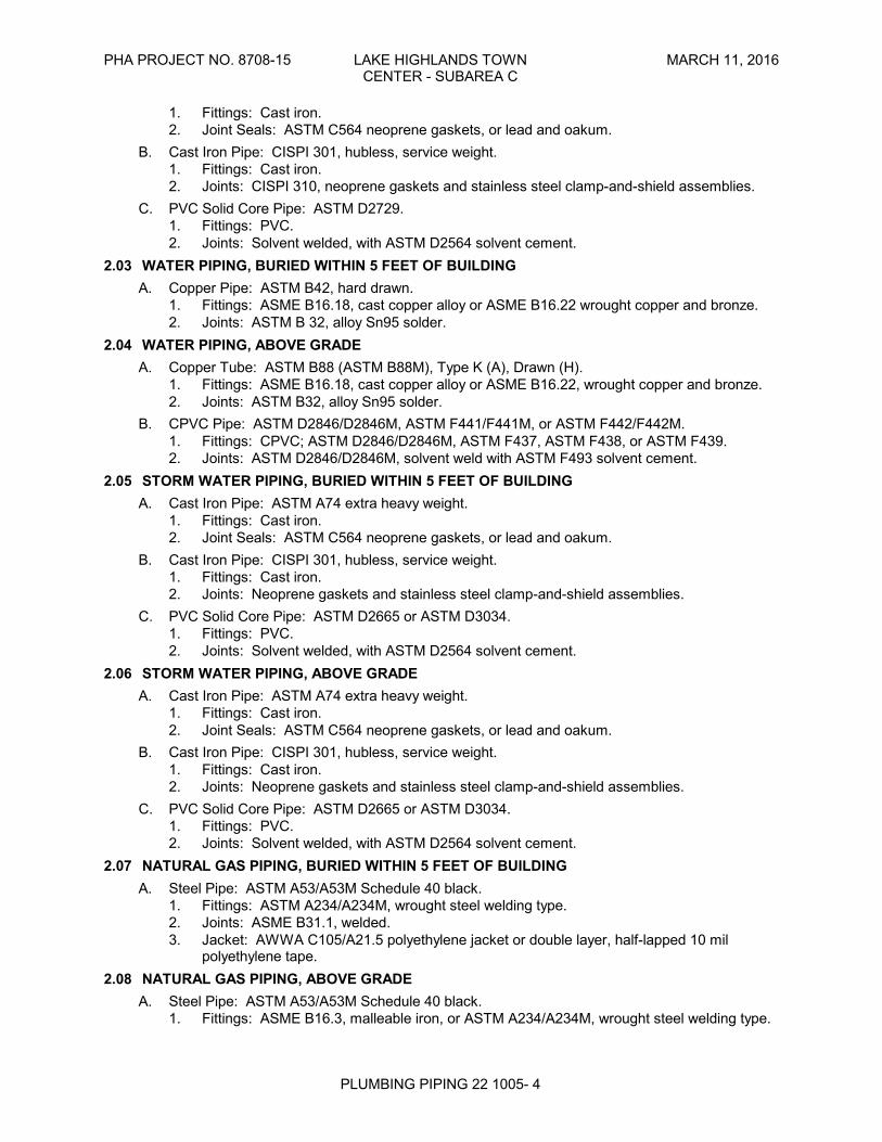
1. Fittings: Cast iron.2. Joint Seals: ASTM C564 neoprene gaskets, or lead and oakum.
B. Cast Iron Pipe: CISPI 301, hubless, service weight.1. Fittings: Cast iron.2. Joints: CISPI 310, neoprene gaskets and stainless steel clamp-and-shield assemblies.
C. PVC Solid Core Pipe: ASTM D2729.1. Fittings: PVC.2. Joints: Solvent welded, with ASTM D2564 solvent cement.
2.03 WATER PIPING, BURIED WITHIN 5 FEET OF BUILDINGA. Copper Pipe: ASTM B42, hard drawn.
1. Fittings: ASME B16.18, cast copper alloy or ASME B16.22 wrought copper and bronze.2. Joints: ASTM B 32, alloy Sn95 solder.
2.04 WATER PIPING, ABOVE GRADEA. Copper Tube: ASTM B88 (ASTM B88M), Type K (A), Drawn (H).
1. Fittings: ASME B16.18, cast copper alloy or ASME B16.22, wrought copper and bronze.2. Joints: ASTM B32, alloy Sn95 solder.
B. CPVC Pipe: ASTM D2846/D2846M, ASTM F441/F441M, or ASTM F442/F442M.1. Fittings: CPVC; ASTM D2846/D2846M, ASTM F437, ASTM F438, or ASTM F439.2. Joints: ASTM D2846/D2846M, solvent weld with ASTM F493 solvent cement.
2.05 STORM WATER PIPING, BURIED WITHIN 5 FEET OF BUILDINGA. Cast Iron Pipe: ASTM A74 extra heavy weight.
1. Fittings: Cast iron.2. Joint Seals: ASTM C564 neoprene gaskets, or lead and oakum.
B. Cast Iron Pipe: CISPI 301, hubless, service weight.1. Fittings: Cast iron.2. Joints: Neoprene gaskets and stainless steel clamp-and-shield assemblies.
C. PVC Solid Core Pipe: ASTM D2665 or ASTM D3034.1. Fittings: PVC.2. Joints: Solvent welded, with ASTM D2564 solvent cement.
2.06 STORM WATER PIPING, ABOVE GRADEA. Cast Iron Pipe: ASTM A74 extra heavy weight.
1. Fittings: Cast iron.2. Joint Seals: ASTM C564 neoprene gaskets, or lead and oakum.
B. Cast Iron Pipe: CISPI 301, hubless, service weight.1. Fittings: Cast iron.2. Joints: Neoprene gaskets and stainless steel clamp-and-shield assemblies.
C. PVC Solid Core Pipe: ASTM D2665 or ASTM D3034.1. Fittings: PVC.2. Joints: Solvent welded, with ASTM D2564 solvent cement.
2.07 NATURAL GAS PIPING, BURIED WITHIN 5 FEET OF BUILDINGA. Steel Pipe: ASTM A53/A53M Schedule 40 black.
1. Fittings: ASTM A234/A234M, wrought steel welding type.2. Joints: ASME B31.1, welded.3. Jacket: AWWA C105/A21.5 polyethylene jacket or double layer, half-lapped 10 mil
polyethylene tape.2.08 NATURAL GAS PIPING, ABOVE GRADE
A. Steel Pipe: ASTM A53/A53M Schedule 40 black.1. Fittings: ASME B16.3, malleable iron, or ASTM A234/A234M, wrought steel welding type.
PHA PROJECT NO. 8708-15 LAKE HIGHLANDS TOWN MARCH 11, 2016CENTER - SUBAREA C
PLUMBING PIPING 22 1005- 5
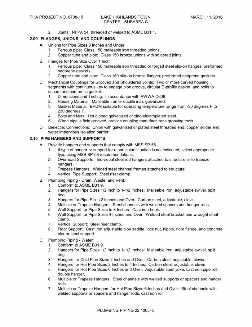
2. Joints: NFPA 54, threaded or welded to ASME B31.1.2.09 FLANGES, UNIONS, AND COUPLINGS
A. Unions for Pipe Sizes 3 Inches and Under:1. Ferrous pipe: Class 150 malleable iron threaded unions.2. Copper tube and pipe: Class 150 bronze unions with soldered joints.
B. Flanges for Pipe Size Over 1 Inch:1. Ferrous pipe: Class 150 malleable iron threaded or forged steel slip-on flanges; preformed
neoprene gaskets.2. Copper tube and pipe: Class 150 slip-on bronze flanges; preformed neoprene gaskets.
C. Mechanical Couplings for Grooved and Shouldered Joints: Two or more curved housingsegments with continuous key to engage pipe groove, circular C-profile gasket, and bolts tosecure and compress gasket.1. Dimensions and Testing: In accordance with AWWA C606.2. Housing Material: Malleable iron or ductile iron, galvanized.3. Gasket Material: EPDM suitable for operating temperature range from -30 degrees F to
230 degrees F.4. Bolts and Nuts: Hot dipped galvanized or zinc-electroplated steel.5. When pipe is field grooved, provide coupling manufacturer's grooving tools.
D. Dielectric Connections: Union with galvanized or plated steel threaded end, copper solder end,water impervious isolation barrier.
2.10 PIPE HANGERS AND SUPPORTSA. Provide hangers and supports that comply with MSS SP-58.
1. If type of hanger or support for a particular situation is not indicated, select appropriatetype using MSS SP-58 recommendations.
2. Overhead Supports: Individual steel rod hangers attached to structure or to trapezehangers.
3. Trapeze Hangers: Welded steel channel frames attached to structure.4. Vertical Pipe Support: Steel riser clamp.
B. Plumbing Piping - Drain, Waste, and Vent:1. Conform to ASME B31.9.2. Hangers for Pipe Sizes 1/2 Inch to 1-1/2 Inches: Malleable iron, adjustable swivel, split
ring.3. Hangers for Pipe Sizes 2 Inches and Over: Carbon steel, adjustable, clevis.4. Multiple or Trapeze Hangers: Steel channels with welded spacers and hanger rods.5. Wall Support for Pipe Sizes to 3 Inches: Cast iron hook.6. Wall Support for Pipe Sizes 4 Inches and Over: Welded steel bracket and wrought steel
clamp.7. Vertical Support: Steel riser clamp.8. Floor Support: Cast iron adjustable pipe saddle, lock nut, nipple, floor flange, and concrete
pier or steel support.C. Plumbing Piping - Water:
1. Conform to ASME B31.9.2. Hangers for Pipe Sizes 1/2 Inch to 1-1/2 Inches: Malleable iron, adjustable swivel, split
ring.3. Hangers for Cold Pipe Sizes 2 Inches and Over: Carbon steel, adjustable, clevis.4. Hangers for Hot Pipe Sizes 2 Inches to 4 Inches: Carbon steel, adjustable, clevis.5. Hangers for Hot Pipe Sizes 6 Inches and Over: Adjustable steel yoke, cast iron pipe roll,
double hanger.6. Multiple or Trapeze Hangers: Steel channels with welded supports or spacers and hanger
rods.7. Multiple or Trapeze Hangers for Hot Pipe Sizes 6 Inches and Over: Steel channels with
welded supports or spacers and hanger rods, cast iron roll.
PHA PROJECT NO. 8708-15 LAKE HIGHLANDS TOWN MARCH 11, 2016CENTER - SUBAREA C
PLUMBING PIPING 22 1005- 6
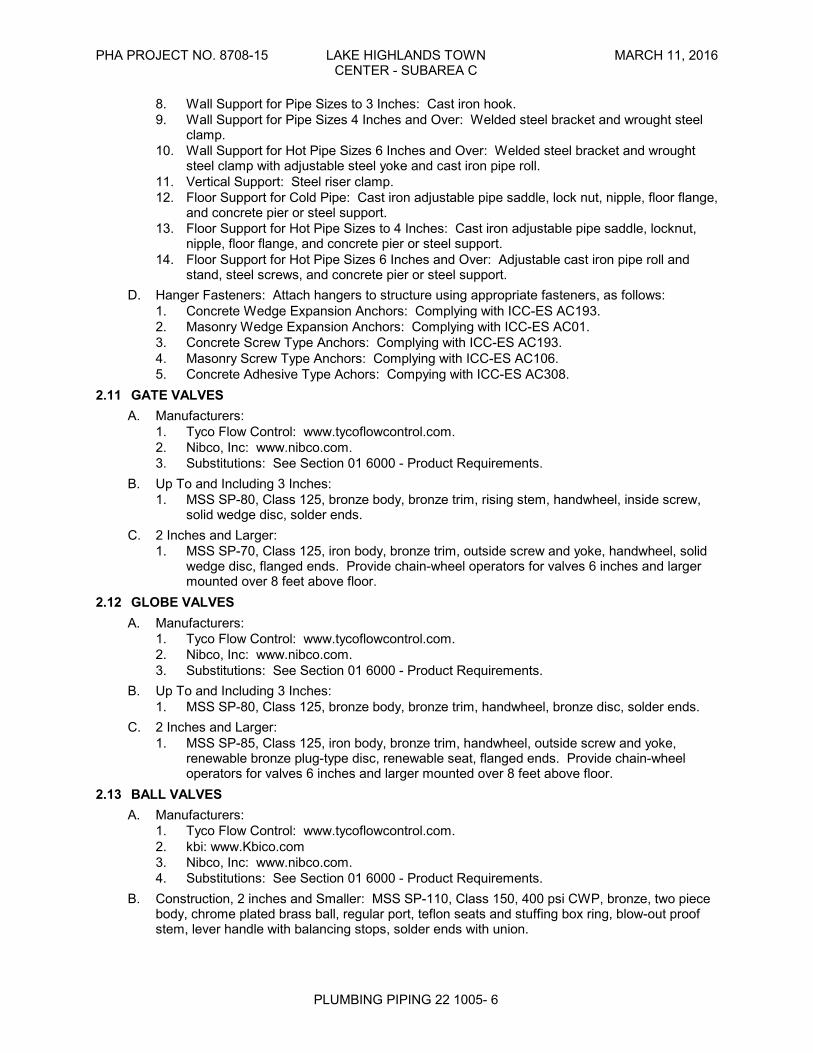
8. Wall Support for Pipe Sizes to 3 Inches: Cast iron hook.9. Wall Support for Pipe Sizes 4 Inches and Over: Welded steel bracket and wrought steel
clamp.10. Wall Support for Hot Pipe Sizes 6 Inches and Over: Welded steel bracket and wrought
steel clamp with adjustable steel yoke and cast iron pipe roll.11. Vertical Support: Steel riser clamp.12. Floor Support for Cold Pipe: Cast iron adjustable pipe saddle, lock nut, nipple, floor flange,
and concrete pier or steel support.13. Floor Support for Hot Pipe Sizes to 4 Inches: Cast iron adjustable pipe saddle, locknut,
nipple, floor flange, and concrete pier or steel support.14. Floor Support for Hot Pipe Sizes 6 Inches and Over: Adjustable cast iron pipe roll and
stand, steel screws, and concrete pier or steel support.D. Hanger Fasteners: Attach hangers to structure using appropriate fasteners, as follows:
1. Concrete Wedge Expansion Anchors: Complying with ICC-ES AC193.2. Masonry Wedge Expansion Anchors: Complying with ICC-ES AC01.3. Concrete Screw Type Anchors: Complying with ICC-ES AC193.4. Masonry Screw Type Anchors: Complying with ICC-ES AC106.5. Concrete Adhesive Type Achors: Compying with ICC-ES AC308.
2.11 GATE VALVESA. Manufacturers:
1. Tyco Flow Control: www.tycoflowcontrol.com.2. Nibco, Inc: www.nibco.com.3. Substitutions: See Section 01 6000 - Product Requirements.
B. Up To and Including 3 Inches:1. MSS SP-80, Class 125, bronze body, bronze trim, rising stem, handwheel, inside screw,
solid wedge disc, solder ends.C. 2 Inches and Larger:
1. MSS SP-70, Class 125, iron body, bronze trim, outside screw and yoke, handwheel, solidwedge disc, flanged ends. Provide chain-wheel operators for valves 6 inches and largermounted over 8 feet above floor.
2.12 GLOBE VALVESA. Manufacturers:
1. Tyco Flow Control: www.tycoflowcontrol.com.2. Nibco, Inc: www.nibco.com.3. Substitutions: See Section 01 6000 - Product Requirements.
B. Up To and Including 3 Inches:1. MSS SP-80, Class 125, bronze body, bronze trim, handwheel, bronze disc, solder ends.
C. 2 Inches and Larger:1. MSS SP-85, Class 125, iron body, bronze trim, handwheel, outside screw and yoke,
renewable bronze plug-type disc, renewable seat, flanged ends. Provide chain-wheeloperators for valves 6 inches and larger mounted over 8 feet above floor.
2.13 BALL VALVESA. Manufacturers:
1. Tyco Flow Control: www.tycoflowcontrol.com.2. kbi: www.Kbico.com3. Nibco, Inc: www.nibco.com.4. Substitutions: See Section 01 6000 - Product Requirements.
B. Construction, 2 inches and Smaller: MSS SP-110, Class 150, 400 psi CWP, bronze, two piecebody, chrome plated brass ball, regular port, teflon seats and stuffing box ring, blow-out proofstem, lever handle with balancing stops, solder ends with union.
PHA PROJECT NO. 8708-15 LAKE HIGHLANDS TOWN MARCH 11, 2016CENTER - SUBAREA C
PLUMBING PIPING 22 1005- 7
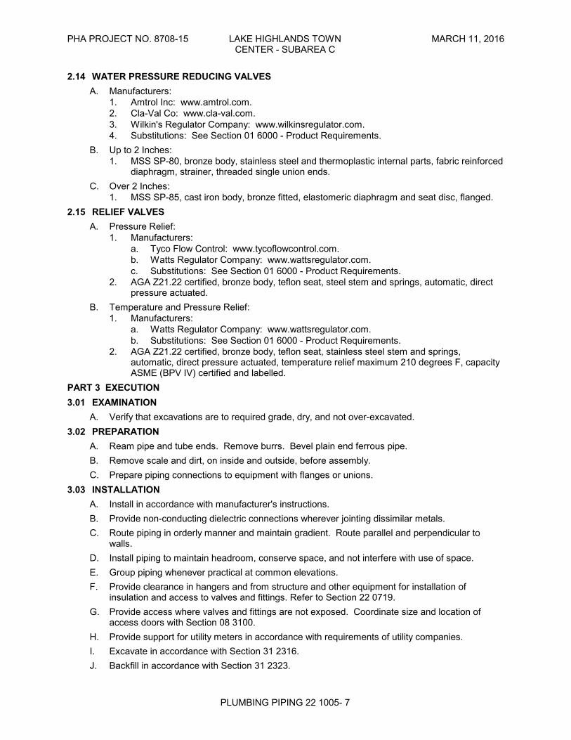
2.14 WATER PRESSURE REDUCING VALVESA. Manufacturers:
1. Amtrol Inc: www.amtrol.com.2. Cla-Val Co: www.cla-val.com.3. Wilkin's Regulator Company: www.wilkinsregulator.com.4. Substitutions: See Section 01 6000 - Product Requirements.
B. Up to 2 Inches:1. MSS SP-80, bronze body, stainless steel and thermoplastic internal parts, fabric reinforced
diaphragm, strainer, threaded single union ends.C. Over 2 Inches:
1. MSS SP-85, cast iron body, bronze fitted, elastomeric diaphragm and seat disc, flanged.2.15 RELIEF VALVES
A. Pressure Relief:1. Manufacturers:
a. Tyco Flow Control: www.tycoflowcontrol.com.b. Watts Regulator Company: www.wattsregulator.com.c. Substitutions: See Section 01 6000 - Product Requirements.
2. AGA Z21.22 certified, bronze body, teflon seat, steel stem and springs, automatic, directpressure actuated.
B. Temperature and Pressure Relief:1. Manufacturers:
a. Watts Regulator Company: www.wattsregulator.com.b. Substitutions: See Section 01 6000 - Product Requirements.
2. AGA Z21.22 certified, bronze body, teflon seat, stainless steel stem and springs,automatic, direct pressure actuated, temperature relief maximum 210 degrees F, capacityASME (BPV IV) certified and labelled.
PART 3 EXECUTION3.01 EXAMINATION
A. Verify that excavations are to required grade, dry, and not over-excavated.3.02 PREPARATION
A. Ream pipe and tube ends. Remove burrs. Bevel plain end ferrous pipe.B. Remove scale and dirt, on inside and outside, before assembly.C. Prepare piping connections to equipment with flanges or unions.
3.03 INSTALLATIONA. Install in accordance with manufacturer's instructions.B. Provide non-conducting dielectric connections wherever jointing dissimilar metals.C. Route piping in orderly manner and maintain gradient. Route parallel and perpendicular to
walls.D. Install piping to maintain headroom, conserve space, and not interfere with use of space.E. Group piping whenever practical at common elevations.F. Provide clearance in hangers and from structure and other equipment for installation of
insulation and access to valves and fittings. Refer to Section 22 0719.G. Provide access where valves and fittings are not exposed. Coordinate size and location of
access doors with Section 08 3100.H. Provide support for utility meters in accordance with requirements of utility companies.I. Excavate in accordance with Section 31 2316.J. Backfill in accordance with Section 31 2323.
PHA PROJECT NO. 8708-15 LAKE HIGHLANDS TOWN MARCH 11, 2016CENTER - SUBAREA C
PLUMBING PIPING 22 1005- 8
K. Install bell and spigot pipe with bell end upstream.L. Install valves with stems upright or horizontal, not inverted.M. Pipe vents from gas pressure reducing valves to outdoors and terminate in weather proof hood.N. Install water piping to ASME B31.9.O. PVC Pipe: Make solvent-welded joints in accordance with ASTM D2855.P. Inserts:
1. Provide inserts for placement in concrete formwork.2. Provide inserts for suspending hangers from reinforced concrete slabs and sides of
reinforced concrete beams.3. Provide hooked rod to concrete reinforcement section for inserts carrying pipe over 4
inches.4. Where concrete slabs form finished ceiling, locate inserts flush with slab surface.5. Where inserts are omitted, drill through concrete slab from below and provide through-bolt
with recessed square steel plate and nut above slab.Q. Pipe Hangers and Supports:
1. Install in accordance with ASME B31.9.2. Support horizontal piping as scheduled.3. Install hangers to provide minimum 1/2 inch space between finished covering and adjacent
work.4. Place hangers within 12 inches of each horizontal elbow.5. Use hangers with 1-1/2 inch minimum vertical adjustment. Design hangers for pipe
movement without disengagement of supported pipe.6. Support vertical piping at every floor. Support riser piping independently of connected
horizontal piping.7. Where several pipes can be installed in parallel and at same elevation, provide multiple or
trapeze hangers.8. Support cast iron drainage piping at every joint.
3.04 APPLICATIONA. Use grooved mechanical couplings and fasteners only in accessible locations.B. Install unions downstream of valves and at equipment or apparatus connections.C. Install brass male adapters each side of valves in copper piped system. Solder adapters to
pipe.D. Install gate valves for shut-off and to isolate equipment, part of systems, or vertical risers.E. Install globe valves for throttling, bypass, or manual flow control services.F. Provide plug valves in natural gas systems for shut-off service.
3.05 TOLERANCESA. Drainage Piping: Establish invert elevations within 1/2 inch vertically of location indicated and
slope to drain at minimum of 1/4 inch per foot slope.B. Water Piping: Slope at minimum of 1/32 inch per foot and arrange to drain at low points.
3.06 DISINFECTION OF DOMESTIC WATER PIPING SYSTEMA. Disinfect water distribution system in accordance with Section 33 1300.B. Prior to starting work, verify system is complete, flushed and clean.C. Ensure Ph of water to be treated is between 7.4 and 7.6 by adding alkali (caustic soda or soda
ash) or acid (hydrochloric).D. Inject disinfectant, free chlorine in liquid, powder, tablet or gas form, throughout system to
obtain 50 to 80 mg/L residual.E. Bleed water from outlets to ensure distribution and test for disinfectant residual at minimum 15
percent of outlets.
PHA PROJECT NO. 8708-15 LAKE HIGHLANDS TOWN MARCH 11, 2016CENTER - SUBAREA C
PLUMBING PIPING 22 1005- 9
F. Maintain disinfectant in system for 24 hours.G. If final disinfectant residual tests less than 25 mg/L, repeat treatment.H. Flush disinfectant from system until residual equal to that of incoming water or 1.0 mg/L.I. Take samples no sooner than 24 hours after flushing, from 10 percent of outlets and from water
entry, and analyze in accordance with AWWA C651.3.07 SERVICE CONNECTIONS
A. Provide new sanitary sewer services. Before commencing work check invert elevationsrequired for sewer connections, confirm inverts and ensure that these can be properlyconnected with slope for drainage and cover to avoid freezing.
B. Provide new water service complete with approved water meter with by-pass valves asrequired.
C. Provide new gas service complete with gas meter and regulators. Gas service distributionpiping to have initial maximum pressure of 11 inch wg. Provide regulators on each line servinggravity type appliances, sized in accordance with equipment.
3.08 SCHEDULESA. Pipe Hanger Spacing:
1. Metal Piping:a. Pipe size: 1/2 inches to 1-1/4 inches:
1) Maximum hanger spacing: 6.5 ft.2) Hanger rod diameter: 3/8 inches.
b. Pipe size: 1-1/2 inches to 2 inches:1) Maximum hanger spacing: 10 ft.2) Hanger rod diameter: 3/8 inch.
c. Pipe size: 2-1/2 inches to 3 inches:1) Maximum hanger spacing: 10 ft.2) Hanger rod diameter: 1/2 inch.
d. Pipe size: 4 inches to 6 inches:1) Maximum hanger spacing: 10 ft.2) Hanger rod diameter: 5/8 inch.
e. Pipe size: 8 inches to 12 inches:1) Maximum hanger spacing: 14 ft.2) Hanger rod diameter: 7/8 inch.
2. Plastic Piping:a. All Sizes:
1) Maximum hanger spacing: 6 ft.2) Hanger rod diameter: 3/8 inch.
END OF SECTION
PHA PROJECT NO. 8708-15 LAKE HIGHLANDS TOWN MARCH 11, 2016CENTER - SUBAREA C
PLUMBING PIPING SPECIALTIES 22 1006- 1
SECTION 22 1006PLUMBING PIPING SPECIALTIES
PART 1 GENERAL1.01 SECTION INCLUDES
A. Roof and floor drains.B. Cleanouts.C. Hose bibbs.D. Hydrants.E. Backflow preventers.F. Water hammer arrestors.G. Interceptors.H. Thermostatic mixing valves.
1.02 RELATED REQUIREMENTSA. Section 22 1005 - Plumbing Piping.B. Section 22 4000 - Plumbing Fixtures.C. Section 22 3000 - Plumbing Equipment.D. Section 26 2717 - Equipment Wiring: Electrical characteristics and wiring connections.
1.03 SUBMITTALSA. See Section 01 3000 - Administrative Requirements, for submittal procedures.B. Product Data: Provide component sizes, rough-in requirements, service sizes, and finishes.
1.04 DELIVERY, STORAGE, AND HANDLINGA. Accept specialties on site in original factory packaging. Inspect for damage.
PART 2 PRODUCTS2.01 DRAINS
A. Manufacturers:1. Josam Company: www.josam.com.2. Jay R. Smith Manufacturing Company: www.jayrsmith.com.3. Zurn Industries, Inc: www.zurn.com.4. Substitutions: See Section 01 6000 - Product Requirements.
B. Roof Drains:1. Assembly: ASME A112.6.4.2. Body: Galvanized cast iron with sump.3. Strainer: Removable polyethylene dome with vandal proof screws.4. Accessories: Coordinate with roofing type, refer to architectural:
a. Membrane flange and membrane clamp with integral gravel stop.b. Adjustable under deck clamp.c. Roof sump receiver.d. Waterproofing flange.e. Controlled flow weir.f. Leveling frame.g. Adjustable extension sleeve for roof insulation.h. Perforated or slotted ballast guard extension for inverted roof.i. Perforated stainless steel ballast guard extension.
C. Roof Overflow Drains:1. Galvanized cast iron body and clamp collar and bottom clamp ring; pipe extended to
daylighted discharge at location indicated on plans.
PHA PROJECT NO. 8708-15 LAKE HIGHLANDS TOWN MARCH 11, 2016CENTER - SUBAREA C
PLUMBING PIPING SPECIALTIES 22 1006- 2
D. Area Drains:1. Assembly: ASME A112.6.4.2. Body: Galvanized cast iron with sump.3. Strainer: Round nickel-bronze.4. Accessories: Membrane flange and membrane clamp with integral gravel stop, with
levelling frame.E. Floor Drain:
2.02 CLEANOUTSA. Manufacturers:
1. Jay R. Smith Manufacturing Company: www.jayrsmith.com.2. Josam Company: www.josam.com.3. Zurn Industries, Inc: www.zurn.com.4. Substitutions: See Section 01 6000 - Product Requirements.
B. Cleanouts at Exterior Surfaced Areas:1. Round cast nickel bronze access frame and non-skid cover.
C. Cleanouts at Exterior Unsurfaced Areas:1. Line type with lacquered cast iron body and round epoxy coated gasketed cover.2. PVC female adapters with PVC finish plug.
D. Cleanouts at Interior Finished Floor Areas:1. Galvanized cast iron body with anchor flange, reversible clamping collar, threaded top
assembly, and round gasketed scored cover in service areas and round gasketeddepressed cover to accept floor finish in finished floor areas.
E. Cleanouts at Interior Finished Wall Areas:1. Line type with lacquered cast iron body and round epoxy coated gasketed cover, and
round stainless steel access cover secured with machine screw.2.03 HOSE BIBBS
A. Manufacturers:1. Jay R. Smith Manufacturing Company: www.jayrsmith.com.2. Watts Regulator Company: www.wattsregulator.com.3. Zurn Industries, Inc: www.zurn.com.4. Arrowhead Brass: www.arrowheadbrass.com5. Substitutions: See Section 01 6000 - Product Requirements.
2.04 HYDRANTSA. Manufacturers:
1. Arrowhead Brass Company: www.arrowheadbrass.com.2. Jay R. Smith Manufacturing Company: www.jayrsmith.com.3. Zurn Industries, Inc: www.zurn.com.4. Arrowhead Brass: www.arrowheadbrass.com5. Substitutions: See Section 01 6000 - Product Requirements.
B. Wall Hydrants:1. ASSE 1019; freeze resistant, self-draining type with chrome plated wall plate hose thread
spout, handwheel, and integral vacuum breaker.2.05 WASHING MACHINE BOXES AND VALVES
A. Box Manufacturers:1. IPS Corporation/Water-Tite: www.ipscorp.com.2. Oatey: www.oatey.com.3. Substitutions: See Section 01 6000 - Product Requirements.
B. Valve Manufacturers:1. IPS Corporation/Water-Tite: www.ipscorp.com.
PHA PROJECT NO. 8708-15 LAKE HIGHLANDS TOWN MARCH 11, 2016CENTER - SUBAREA C
PLUMBING PIPING SPECIALTIES 22 1006- 3
2. Zurn Industries, Inc: www.zurn.com.3. Oatey: www.oatey.com4. Substitutions: See Section 01 6000 - Product Requirements.
C. Description: Plastic preformed rough-in box with brass long shank valves with wheel handles,socket for 2 inch waste, slip in finishing cover.
2.06 REFRIGERATOR VALVE AND RECESSED BOXA. Box Manufacturers:
1. IPS Corporation/Water-Tite: www.ipscorp.com.2. Oatey: www.oatey.com.3. Substitutions: See Section 01 6000 - Product Requirements.
B. Valve Manufacturers:1. IPS Corporation/Water-Tite: www.ipscorp.com.2. Zurn Industries, Inc: www.zurn.com.3. Oatey: www.oatey.com4. Substitutions: See Section 01 6000 - Product Requirements.
C. Description: Plastic preformed rough-in box with brass valves with wheel handle, slip infinishing cover.
2.07 BACKFLOW PREVENTERSA. Manufacturers:
1. Watts Regulator Company: www.wattsregulator.com.2. Zurn Industries, Inc: www.zurn.com.3. Substitutions: See Section 01 6000 - Product Requirements.
B. Reduced Pressure Backflow Preventers:1. ASSE 1013; bronze body with bronze internal parts and stainless steel springs; two
independently operating, spring loaded check valves; diaphragm type differential pressurerelief valve located between check valves; third check valve that opens under backpressure in case of diaphragm failure; non-threaded vent outlet; assembled with two gatevalves, strainer, and four test cocks.
2.08 DOUBLE CHECK VALVE ASSEMBLIESA. Manufacturers:
1. Watts Regulator Company: www.wattsregulator.com.2. Zurn Industries, Inc: www.zurn.com.3. Substitutions: See Section 01 6000 - Product Requirements.
B. Double Check Valve Assemblies:1. ASSE 1012; Bronze body with corrosion resistant internal parts and stainless steel springs;
two independently operating check valves with intermediate atmospheric vent.2.09 WATER HAMMER ARRESTORS
A. Manufacturers:1. Jay R. Smith Manufacturing Company: www.jayrsmith.com.2. Watts Regulator Company: www.wattsregulator.com.3. Zurn Industries, Inc: www.zurn.com.4. Substitutions: See Section 01 6000 - Product Requirements.
B. Water Hammer Arrestors:1. Stainless steel construction, bellows type sized in accordance with PDI-WH 201,
precharged suitable for operation in temperature range -100 to 300 degrees F andmaximum 250 psi working pressure.
2.10 MIXING VALVESA. Thermostatic Mixing Valves:
1. Manufacturers:
PHA PROJECT NO. 8708-15 LAKE HIGHLANDS TOWN MARCH 11, 2016CENTER - SUBAREA C
PLUMBING PIPING SPECIALTIES 22 1006- 4
a. Leonard Valve Company: www.leonardvalve.com.b. Honeywell Water Controls: http://yourhome.honeywell.com.c. Substitutions: See Section 01 6000 - Product Requirements.
2. Valve: Chrome plated cast brass body, stainless steel or copper alloy bellows, integraltemperature adjustment.
B. Pressure Balanced Mixing Valves:1. Manufacturers:
a. Delta Faucet Company: www.deltafaucet.com.b. H.G. Specialties: www.hgspec.com.c. CFG by Moen: www.cfgonline.comd. Substitutions: See Section 01 6000 - Product Requirements.
2. Valve: Chrome plated cast brass body, stainless steel cylinder, integral temperatureadjustment.
PART 3 EXECUTION3.01 INSTALLATION
A. Install in accordance with manufacturer's instructions.B. Extend cleanouts to finished floor or wall surface. Lubricate threaded cleanout plugs with
mixture of graphite and linseed oil. Ensure clearance at cleanout for rodding of drainagesystem.
C. Encase exterior cleanouts in concrete flush with grade.D. Install floor cleanouts at elevation to accommodate finished floor.E. Install approved portable water protection devices on plumbing lines where contamination of
domestic water may occur; on boiler feed water lines, janitor rooms, fire sprinkler systems,premise isolation, irrigation systems, flush valves, interior and exterior hose bibbs.
F. Pipe relief from backflow preventer to nearest drain.G. Install air chambers on hot and cold water supply piping to each fixture or group of fixtures
(each washroom). Fabricate same size as supply pipe or 3/4 inch minimum, and minimum 18inches long.
END OF SECTION
PHA PROJECT NO. 8708-15 LAKE HIGHLANDS TOWN MARCH 11, 2016CENTER - SUBAREA C
PLUMBING EQUIPMENT 22 3000- 1
SECTION 22 3000PLUMBING EQUIPMENT
PART 1 GENERAL1.01 SECTION INCLUDES
A. Water Heaters.1.02 RELATED REQUIREMENTS
A. Section 26 2717 - Equipment Wiring: Electrical characteristics and wiring connections.1.03 REFERENCE STANDARDS
A. UL 174 - Standard for Household Electric Storage Tank Water Heaters; UnderwritersLaboratories Inc.; Current Edition, Including All Revisions.
B. UL 1453 - Standard for Electric Booster and Commercial Storage Tank Water Heaters;Underwriters Laboratories Inc.; Current Edition, Including All Revisions.
1.04 SUBMITTALSA. See Section 01 3000 - Administrative Requirements, for submittals procedures.B. Product Data:
1. Provide dimension drawings of water heaters indicating components and connections toother equipment and piping.
2. Provide electrical characteristics and connection requirements.C. Warranty: Submit manufacturer warranty and ensure forms have been completed in Owner's
name and registered with manufacturer.1.05 CERTIFICATIONS
A. Water Heaters: NSF approved.B. Electric Water Heaters: UL listed and labeled to UL 174 or UL 1453.C. Products Requiring Electrical Connection: Listed and classified by Underwriters Laboratories
Inc., as suitable for the purpose specified and indicated.1.06 DELIVERY, STORAGE, AND HANDLING
A. Provide temporary inlet and outlet caps. Maintain caps in place until installation.1.07 WARRANTY
A. See Section 01 7800 - Closeout Submittals, for additional warranty requirements.B. Provide five year manufacturer warranty for domestic water heaters.
PART 2 PRODUCTS2.01 WATER HEATER MANUFACTURERS
A. A.O. Smith Water Products Co: www.hotwater.com.B. Rheem Manufacturing Company: www.rheem.com.C. Substitutions: See Section 01 6000 - Product Requirements.
2.02 RESIDENTIAL ELECTRIC WATER HEATERSA. Type: Automatic, electric, vertical storage.B. Performance: Refer to schedule on drawings.C. Electrical Characteristics:
1. 240 volts, single phase.D. Tank: Glass lined welded steel, thermally insulated with one inch thick glass fiber; encased in
corrosion-resistant steel jacket; baked-on enamel finish.
PHA PROJECT NO. 8708-15 LAKE HIGHLANDS TOWN MARCH 11, 2016CENTER - SUBAREA C
PLUMBING EQUIPMENT 22 3000- 2
E. Controls: Automatic water thermostat with externally adjustable temperature range from 120 to170 degrees F, flanged or screw-in nichrome elements, enclosed controls and electrical junctionbox . Wire double element units so elements do not operate simultaneously.
F. Accessories: Provide:1. Water Connections: Brass.2. Drain Valve.3. Anode: Magnesium4. Temperature and Pressure Relief Valve: ASME labelled.
PART 3 EXECUTION3.01 INSTALLATION
A. Install plumbing equipment in accordance with manufacturer's instructions, as required by code,and complying with conditions of certification, if any.
B. Coordinate with plumbing piping and related electrical work to achieve operating system.END OF SECTION
PHA PROJECT NO. 8708-15 LAKE HIGHLANDS TOWN MARCH 11, 2016CENTER - SUBAREA C
PLUMBING FIXTURES 22 4000- 1
SECTION 22 4000PLUMBING FIXTURES
PART 1 GENERAL1.01 SECTION INCLUDES
A. Water closets.B. Lavatories.C. Sinks.D. Service sinks.E. Electric water coolers.F. Bathtubs.G. Showers.
1.02 RELATED REQUIREMENTSA. Section 07 9005 - Joint Sealers: Seal fixtures to walls and floors.B. Section 22 1005 - Plumbing Piping.C. Section 22 1006 - Plumbing Piping Specialties.D. Section 22 3000 - Plumbing Equipment.E. Section 26 2717 - Equipment Wiring: Electrical characteristics and wiring connections.
1.03 SUBMITTALSA. See Section 01 3000 - Administrative Requirements, for submittal procedures.B. Product Data: Provide catalog illustrations of fixtures, sizes, rough-in dimensions, utility sizes,
trim, and finishes.C. Warranty: Submit manufacturer warranty and ensure forms have been completed in Owner's
name and registered with manufacturer.1.04 REGULATORY REQUIREMENTS
A. Products Requiring Electrical Connection: Listed and classified by Underwriters LaboratoriesInc., as suitable for the purpose specified and indicated.
1.05 DELIVERY, STORAGE, AND HANDLINGA. Accept fixtures on site in factory packaging. Inspect for damage.B. Protect installed fixtures from damage by securing areas and by leaving factory packaging in
place to protect fixtures and prevent use.1.06 WARRANTY
A. See Section 01 7800 - Closeout Submittals, for additional warranty requirements.B. Provide five year manufacturer warranty for electric water cooler.
PART 2 PRODUCTS2.01 FLUSH VALVE WATER CLOSETS
A. Water Closets: Vitreous china, ASME A112.19.2, floor mounted, siphon jet flush action, chinabolt caps.1. Flush Volume: 1.6 gallon, maximum.2. Flush Valve: Exposed (top spud).3. Flush Operation: Manual, oscillating handle.4. Handle Height: 44 inches or less.5. Manufacturers:
a. American Standard Inc: www.americanstandard.com.b. Kohler Company: www.kohler.com.c. Zurn industries, Inc: www.zurn.com.
PHA PROJECT NO. 8708-15 LAKE HIGHLANDS TOWN MARCH 11, 2016CENTER - SUBAREA C
PLUMBING FIXTURES 22 4000- 2
d. Substitutions: See Section 01 6000 - Product Requirements.B. Flush Valves: ASME A112.18.1, diaphragm type, complete with vacuum breaker stops and
accessories.1. Sensor-Operated Type: Solenoid operator, low voltage hard-wired, infrared sensor and
over-ride push button.2. Exposed Type: Chrome plated, escutcheon, integral screwdriver stop.3. Manufacturers:
a. Sloan Valve Company: www.sloanvalve.com.b. Zurn Industries, Inc: www.zurn.com.c. Moen: www.moen.comd. Substitutions: See Section 01 6000 - Product Requirements.
C. Seats:1. Manufacturers:
a. Bemis Manufacturing Company: www.bemismfg.com.b. Church Seat Company: www.churchseats.com.c. Olsonite: www.olsonite.com.d. Zurn industries, Inc: www.zurn.com.e. Substitutions: See Section 01 6000 - Product Requirements.
2.02 TANK TYPE WATER CLOSETSA. Tank Type Water Closet Manufacturers:
1. American Standard Inc: www.americanstandard.com.2. Kohler Company: www.kohler.com.3. Zurn industries, Inc: www.zurn.com.4. ProFlo: www.proflo.com5. Substitutions: See Section 01 6000 - Product Requirements.
B. Bowl: ASME A112.19.2; floor mounted, vitreous china reverse trap, close-coupled closetcombination with regular rim, insulated vitreous china closet tank with fittings and lever flushingvalve, bolt caps.1. Water Consumption: Maximum 1.6 gallon per flush.
C. Seat Manufacturers:1. Bemis Manufacturing Company: www.bemismfg.com.2. Church Seat Company: www.churchseats.com.3. Olsonite: www.olsonite.com.4. Substitutions: See Section 01 6000 - Product Requirements.
D. Seat: Solid white plastic, open front, extended back, less cover, complete with self-sustaininghinge.
2.03 LAVATORIESA. Lavatory Manufacturers:
1. American Standard Inc: www.americanstandard.com.2. Kohler Company: www.kohler.com.3. Pro-flow: www.proflow.com4. Zurn industries, Inc: www.zurn.com.5. Substitutions: See Section 01 6000 - Product Requirements.
B. Vitreous China Wall Hung Basin: ASME A112.19.2; vitreous china wall hung lavatory, with 4inch high back, rectangular basin with splash lip, front overflow, and soap depression.
C. Steel Counter Top Basin: ASME A112.19.4M; porcelain on steel self-rimming counter toplavatory, drillings on 4 inch centers, front overflow, soap depression, seal of putty, calking, orconcealed vinyl gasket.
D. Vitreous China Counter Top Basin: ASME A112.19.2; vitreous china self-rimming counter toplavatory, drillings on 4 inch centers, front overflow, soap depression, seal of putty, calking, orconcealed vinyl gasket.
PHA PROJECT NO. 8708-15 LAKE HIGHLANDS TOWN MARCH 11, 2016CENTER - SUBAREA C
PLUMBING FIXTURES 22 4000- 3
E. Supply Faucet Manufacturers:1. American Standard Inc: www.americanstandard.com.2. Pro-flow: www.proflow.com3. Kohler Company: www.kohler.com.4. cfg by Moen: www.cfgonline.com5. Zurn industries, Inc: www.zurn.com.6. Substitutions: See Section 01 6000 - Product Requirements.
F. Supply Faucet: ASME A112.18.1; chrome plated combination supply fitting with pop-up waste,water economy aerator with maximum flow of 2.2 gallons per minute, indexed handles.
G. Sensor Operated Faucet: Cast brass, chrome plated, deck mounted with sensor located onneck of spout.1. Spout Style: Standard.2. Power Supply: 24 VAC.
a. Cord and plug.b. For 24V applications, provide transformer.
3. Mixing Valve: Internal, automatic.4. Water Supply: 3/8 inch compression connections.5. Aerator: Vandal resistant, 0.5 GPM, laminar flow device. 6. Finish: Polished chrome.7. Sensor Operated Faucet Manufacturers:
a. American Standard Inc: www.americanstandard.com.b. The Chicago Faucet Company: www.chicagofaucets.com.c. Moen Incorporated: www.moen.com.d. Sloan Valve Company: www.sloanvalve.com.e. Zurn industries, Inc: www.zurn.com.f. Substitutions: See Section 01 6000 - Product Requirements.
H. Accessories:1. Offset waste with perforated open strainer.2. Wheel handle stops.3. Carrier:
a. Manufacturers:1) JOSAM Company: www.josam.com.2) Zurn Industries, Inc: www.zurn.com.3) Substitutions: See Section 01 6000 - Product Requirements.
2.04 SINKSA. Sink Manufacturers:
1. American Standard Inc: www.americanstandard.com.2. Kohler Company: www.kohler.com.3. Substitutions: See Section 01 6000 - Product Requirements.
B. Single Compartment Bowl: ASME A112.19.3; 20 gage thick, Type 302 stainless steel, selfrimming and undercoated, with ledge back drilled for trim.1. Drain: 1-1/2 inch chromed brass drain.
C. Double Compartment Bowl: ASME A112.19.3; 20 gage thick, Type 302 stainless steel, selfrimming and undercoated, with ledge back drilled for trim.1. Drain: 1-1/2 inch chromed brass drain.
D. Enamelled Bowl: ASME A112.19.4M; steel, porcelain enamelled, single compartment,self-rimming and undercoated, with 3-1/2 inch diameter crumb cup and chromed brass tailpiece,ledge back drilled for trim.
2.05 BATHTUBS AND SHOWERSA. Bathtub Manufacturers:
1. American Standard Inc: www.americanstandard.com.
PHA PROJECT NO. 8708-15 LAKE HIGHLANDS TOWN MARCH 11, 2016CENTER - SUBAREA C
PLUMBING FIXTURES 22 4000- 4
2. Kohler Company: www.kohler.com.3. Hamilton: www.hamiltonbathware.com4. Substitutions: See Section 01 6000 - Product Requirements.
B. Bathtub:1. ANSI Z124.1.2; molded glass fiber reinforced polyester, with slip-resistant bottom surface,
contoured shape, color as selected.C. Bath and Shower Trim: ASME A112.18.1; concealed shower and over rim supply with diverter
spout, pressure balanced mixing valve, bent shower arm with adjustable spray ball jointshowerhead with maximum 2.5 gallons per minute flow and escutcheon, lever operated pop-upwaste and overflow.
2.06 SHOWER RECEPTORSA. Solid Surfacing Shower Receptors: Solid plastic resin casting, self-supporting, for installation
over conventional subfloor; complying with ANSI Z124.1.2.1. Material: Complying with ISSFA-2 and NEMA LD 3; acrylic or polyester resin, mineral filler,
and pigments; homogenous, non-porous and capable of being worked and repaired usingstandard woodworking tools; no surface coating; color and pattern consistent throughoutthickness.
2. Surface Burning Characteristics: Flame spread 25, maximum; smoke developed 450,maximum; when tested in accordance with ASTM E84.
3. Finish on Exposed Surfaces: Matte, gloss rating of 5 to 20.4. Color and Pattern: As indicated on drawings.5. Manufacturers:
a. Transolid, Inc: www.transolid.com.b. Sterling, Inc..c. Substitutions: See Section 01 6000 - Product Requirements.
B. Drain Trim: Removable chrome plated strainer, tail piece.2.07 SHOWERS
A. Shower Manufacturers:1. Sterling, Inc.2. Substitutions: See Section 01 6000 - Product Requirements.
B. Cabinet: ANSI Z124.1.2 reinforced glass fiber, 32 by 32 by 75 inches with stone texture,integral receptor, soap dish, integral seat, removable chrome plated strainer, tail piece, color asselected.
C. Trim: ASME A112.18.1; concealed shower supply with pressure balanced mixing valves,integral service stops, bent shower arm with adjustable spray ball joint shower head withmaximum flow, and escutcheon.
D. Shower Head:1. ASME A112.18.1; chrome plated vandal-proof institutional head with integral wall bracket,
built-in 2.5 gpm flow control.2.08 ELECTRIC WATER COOLERS
A. Electric Water Cooler Manufacturers:1. Tri Palm International/Oasis: www.tripalmint.com.2. Elkay Manufacturing Company: www.elkay.com.3. Substitutions: See Section 01 6000 - Product Requirements.
B. Water Cooler: Electric, mechanically refrigerated; surface handicapped mounted; stainlesssteel top, vinyl on steel body, elevated anti-squirt bubbler with stream guard, automatic streamregulator, push button, mounting bracket; integral air cooled condenser and stainless steelgrille.1. Capacity: 8 gallons per minute of 50 degrees F water with inlet at 80 degrees F and room
temperature of 90 degrees F, when tested in accordance with ASHRAE Std 18.
PHA PROJECT NO. 8708-15 LAKE HIGHLANDS TOWN MARCH 11, 2016CENTER - SUBAREA C
PLUMBING FIXTURES 22 4000- 5
2. Electrical: 115 V, 60 Hertz compressor, 6 foot cord and plug for connection to electricwiring system including grounding connector.
2.09 SERVICE SINKSA. Bowl: 36 by 24 by 10 inch high white molded stone, floor mounted, with one inch wide
shoulders, vinyl bumper guard, stainless steel strainer.B. Trim: ASME A112.18.1 exposed wall type supply with cross handles, spout wall brace, vacuum
breaker, hose end spout, strainers, eccentric adjustable inlets, integral screwdriver stops withcovering caps and adjustable threaded wall flanges.
C. Accessories:1. 5 feet of 1/2 inch diameter plain end reinforced plastic hose.2. Hose clamp hanger.3. Mop hanger.
PART 3 EXECUTION3.01 EXAMINATION
A. Verify that walls and floor finishes are prepared and ready for installation of fixtures.B. Verify that electric power is available and of the correct characteristics.C. Confirm that millwork is constructed with adequate provision for the installation of counter top
lavatories and sinks.3.02 PREPARATION
A. Rough-in fixture piping connections in accordance with minimum sizes indicated in fixturerough-in schedule for particular fixtures.
3.03 INSTALLATIONA. Install components level and plumb.B. Seal fixtures to wall and floor surfaces with sealant as specified in Section 07 9005, color to
match fixture.3.04 INTERFACE WITH WORK OF OTHER SECTIONS
A. Review millwork shop drawings. Confirm location and size of fixtures and openings beforerough-in and installation.
3.05 ADJUSTINGA. Adjust stops or valves for intended water flow rate to fixtures without splashing, noise, or
overflow.3.06 CLEANING
A. Clean plumbing fixtures and equipment.3.07 PROTECTION
A. Protect installed products from damage due to subsequent construction operations.B. Repair or replace damaged products before Date of Substantial Completion.
END OF SECTION
PHA PROJECT NO. 8708-15 LAKE HIGHLANDS TOWN MARCH 11, 2016CENTER - SUBAREA C
COMMON MOTOR REQUIREMENTS FOR HVAC EQUIPMENT 23 0513- 1
SECTION 23 0513COMMON MOTOR REQUIREMENTS FOR HVAC EQUIPMENT
PART 1 GENERAL1.01 SECTION INCLUDES
A. Single phase electric motors.1.02 RELATED REQUIREMENTS
A. Section 26 2717 - Equipment Wiring: Electrical characteristics and wiring connections.1.03 REFERENCE STANDARDS
A. NEMA MG 1 - Motors and Generators; National Electrical Manufacturers Association; 2009,Revision 1 - 2010.
B. NFPA 70 - National Electrical Code; National Fire Protection Association; Most Recent EditionAdopted by Authority Having Jurisdiction, Including All Applicable Amendments andSupplements.
1.04 SUBMITTALSA. See Section 01 3000 - Administrative Requirements, for submittal procedures.B. Product Data: Provide wiring diagrams with electrical characteristics and connection
requirements.1.05 QUALITY ASSURANCE
A. Conform to NFPA 70.B. Products Requiring Electrical Connection: Listed and classified by Underwriters Laboratories
Inc. as suitable for the purpose specified and indicated.1.06 DELIVERY, STORAGE, AND HANDLING
A. Protect motors stored on site from weather and moisture by maintaining factory covers andsuitable weather-proof covering. For extended outdoor storage, remove motors from equipmentand store separately.
1.07 WARRANTYA. See Section 01 7800 - Closeout Submittals, for additional warranty requirements.
PART 2 PRODUCTS2.01 GENERAL CONSTRUCTION AND REQUIREMENTS
A. Electrical Service: Refer to Section 26 2717 for required electrical characteristics.B. Construction:
1. Open drip-proof type except where specifically noted otherwise.2. Design for continuous operation in 40 degrees C environment.3. Design for temperature rise in accordance with NEMA MG 1 limits for insulation class,
service factor, and motor enclosure type.C. Visible Nameplate: Indicating motor horsepower, voltage, phase, cycles, RPM, full load amps,
locked rotor amps, frame size, manufacturer's name and model number, service factor, powerfactor, efficiency.
D. Wiring Terminations:1. Provide terminal lugs to match branch circuit conductor quantities, sizes, and materials
indicated. Enclose terminal lugs in terminal box sized to NFPA 70, threaded for conduit.2. For fractional horsepower motors where connection is made directly, provide threaded
conduit connection in end frame.2.02 APPLICATIONS2.03 SINGLE PHASE POWER - SPLIT PHASE MOTORS
A. Starting Torque: Less than 150 percent of full load torque.
PHA PROJECT NO. 8708-15 LAKE HIGHLANDS TOWN MARCH 11, 2016CENTER - SUBAREA C
COMMON MOTOR REQUIREMENTS FOR HVAC EQUIPMENT 23 0513- 2
B. Starting Current: Up to seven times full load current.C. Breakdown Torque: Approximately 200 percent of full load torque.D. Drip-proof Enclosure: Class A (50 degrees C temperature rise) insulation, NEMA Service
Factor, prelubricated sleeve or ball bearings.E. Enclosed Motors: Class A (50 degrees C temperature rise) insulation, 1.0 Service Factor,
prelubricated ball bearings.2.04 SINGLE PHASE POWER - PERMANENT-SPLIT CAPACITOR MOTORS
A. Starting Torque: Exceeding one fourth of full load torque.B. Starting Current: Up to six times full load current.C. Multiple Speed: Through tapped windings.D. Open Drip-proof or Enclosed Air Over Enclosure: Class A (50 degrees C temperature rise)
insulation, minimum 1.0 Service Factor, prelubricated sleeve or ball bearings, automatic resetoverload protector.
2.05 SINGLE PHASE POWER - CAPACITOR START MOTORSA. Starting Torque: Three times full load torque.B. Starting Current: Less than five times full load current.C. Pull-up Torque: Up to 350 percent of full load torque.D. Breakdown Torque: Approximately 250 percent of full load torque.E. Motors: Capacitor in series with starting winding; provide capacitor-start/capacitor-run motors
with two capacitors in parallel with run capacitor remaining in circuit at operating speeds.F. Drip-proof Enclosure: Class A (50 degrees C temperature rise) insulation, NEMA Service
Factor, prelubricated sleeve bearings.G. Enclosed Motors: Class A (50 degrees C temperature rise) insulation, 1.0 Service Factor,
prelubricated ball bearings.PART 3 EXECUTION3.01 INSTALLATION
A. Install in accordance with manufacturer's instructions.B. Install securely on firm foundation. Mount ball bearing motors with shaft in any position.C. Check line voltage and phase and ensure agreement with nameplate.
END OF SECTION
PHA PROJECT NO. 8708-15 LAKE HIGHLANDS TOWN MARCH 11, 2016CENTER - SUBAREA C
IDENTIFICATION FOR HVAC PIPING AND EQUIPMENT 23 0553- 1
SECTION 23 0553IDENTIFICATION FOR HVAC PIPING AND EQUIPMENT
PART 1 GENERAL1.01 SECTION INCLUDES
A. Nameplates.B. Tags.C. Stencils.
1.02 RELATED REQUIREMENTSA. Section 09 9000 - Painting and Coating: Identification painting.
1.03 REFERENCE STANDARDSA. ASTM D709 - Standard Specification for Laminated Thermosetting Materials; 2001
(Reapproved 2007).1.04 SUBMITTALS
A. See Section 01 3000 - Administrative Requirements, for submittal procedures.PART 2 PRODUCTS2.01 IDENTIFICATION APPLICATIONS
A. Air Handling and Condensing Units: Nameplates.B. Thermostats: Nameplates.
2.02 NAMEPLATESA. Manufacturers:
1. Advanced Graphic Engraving: www.advancedgraphicengraving.com.2. Kolbi Pipe Marker Co.: www.kolbipipemarkers.com.3. Seton Identification Products: www.seton.com.4. Substitutions: See Section 01 6000 - Product Requirements.5. Letter Color: White.6. Letter Height: 1/4 inch.7. Background Color: Black.8. Plastic: Conform to ASTM D709.
2.03 TAGSA. Manufacturers:
1. Advanced Graphic Engraving: www.advancedgraphicengraving.com.2. Brady Corporation: www.bradycorp.com.3. Kolbi Pipe Marker Co.: www.kolbipipemarkers.com.4. Substitutions: See Section 01 6000 - Product Requirements.
B. Plastic Tags: Laminated three-layer plastic with engraved black letters on light contrastingbackground color. Tag size minimum 1-1/2 inch diameter.
C. Metal Tags: Brass with stamped letters; tag size minimum 1-1/2 inch diameter with smoothedges.
2.04 STENCILSA. Manufacturers:
1. Brady Corporation: www.bradycorp.com.2. Kolbi Pipe Marker Co.: www.kolbipipemarkers.com.3. Seton Identification Products: www.seton.com.4. Substitutions: See Section 01 6000 - Product Requirements.
B. Stencils: With clean cut symbols and letters of following size:
PHA PROJECT NO. 8708-15 LAKE HIGHLANDS TOWN MARCH 11, 2016CENTER - SUBAREA C
IDENTIFICATION FOR HVAC PIPING AND EQUIPMENT 23 0553- 2
1. 3/4 to 1-1/4 inch Outside Diameter of Insulation or Pipe: 8 inch long color field, 1/2 inchhigh letters.
2. 1-1/2 to 2 inch Outside Diameter of Insulation or Pipe: 8 inch long color field, 3/4 inch highletters.
3. 2-1/2 to 6 inch Outside Diameter of Insulation or Pipe: 12 inch long color field, 1-1/4 inchhigh letters.
PART 3 EXECUTION3.01 PREPARATION
A. Degrease and clean surfaces to receive adhesive for identification materials.B. Prepare surfaces in accordance with Section 09 9000 for stencil painting.
3.02 INSTALLATIONA. Install nameplates with corrosive-resistant mechanical fasteners, or adhesive. Apply with
sufficient adhesive to ensure permanent adhesion and seal with clear lacquer.END OF SECTION
PHA PROJECT NO. 8708-15 LAKE HIGHLANDS TOWN MARCH 11, 2016CENTER - SUBAREA C
DUCT INSULATION 23 0713- 1
SECTION 23 0713DUCT INSULATION
PART 1 GENERAL1.01 SECTION INCLUDES
A. Duct insulation.B. Duct Liner.C. Insulation jackets.
1.02 RELATED REQUIREMENTSA. Section 22 0553 - Identification for Plumbing Piping and Equipment.B. Section 23 0553 - Identification for HVAC Piping and Equipment.
1.03 REFERENCE STANDARDSA. ASTM C518 - Standard Test Method for Steady-State Thermal Transmission Properties by
Means of the Heat Flow Meter Apparatus; 2004.B. ASTM C553 - Specification for Mineral Fiber Blanket Thermal Insulation for Commercial and
Industrial Applications; 2008.C. ASTM C612 - Standard Specification for Mineral Fiber Block and Board Thermal Insulation;
2009.D. ASTM C916 - Standard Specification for Adhesives for Duct Thermal Insulation; 1985
(Reapproved 2007).E. ASTM C1338 - Standard Test Method for Determining Fungi Resistance of Insulation Materials
and Facings; 2008.F. ASTM E84 - Standard Test Method for Surface Burning Characteristics of Building Materials;
2010.G. ASTM G21 - Standard Practice for Determining Resistance of Synthetic Polymeric Materials to
Fungi; 1996 (Reapproved 2002).H. NFPA 255 - Standard Method of Test of Surface Burning Characteristics of Building Materials;
National Fire Protection Association; 2006.I. SMACNA (DCS) - HVAC Duct Construction Standards - Metal and Flexible; Sheet Metal and Air
Conditioning Contractors' National Association; 2005.J. UL 723 - Standard for Test for Surface Burning Characteristics of Building Materials;
Underwriters Laboratories Inc.; Current Edition, Including All Revisions.1.04 SUBMITTALS
A. See Section 01 3000 - Administrative Requirements, for submittal procedures.B. Product Data: Provide product description, thermal characteristics, list of materials and
thickness for each service, and locations.1.05 DELIVERY, STORAGE, AND HANDLING
A. Accept materials on site in original factory packaging, labelled with manufacturer's identification,including product density and thickness.
B. Protect insulation from weather and construction traffic, dirt, water, chemical, and mechanicaldamage, by storing in original wrapping.
1.06 FIELD CONDITIONSA. Maintain ambient temperatures and conditions required by manufacturers of adhesives,
mastics, and insulation cements.B. Maintain temperature during and after installation for minimum period of 24 hours.
PHA PROJECT NO. 8708-15 LAKE HIGHLANDS TOWN MARCH 11, 2016CENTER - SUBAREA C
DUCT INSULATION 23 0713- 2
PART 2 PRODUCTS2.01 REQUIREMENTS FOR ALL PRODUCTS OF THIS SECTION
A. Surface Burning Characteristics: Flame spread/Smoke developed index of 25/50, maximum,when tested in accordance with ASTM E 84, NFPA 255, or UL 723.
2.02 GLASS FIBER, FLEXIBLEA. Manufacturer:
1. Knauf Insulation: www.knaufusa.com.2. Johns Manville Corporation: www.jm.com.3. Owens Corning Corp: www.owenscorning.com.4. CertainTeed Corporation; : www.certainteed.com.5. Substitutions: See Section 01 6000 - Product Requirements.
B. Insulation: ASTM C553; flexible, noncombustible blanket.1. 'K' value: 0.36 at 75 degrees F, when tested in accordance with ASTM C518.
C. Vapor Barrier Jacket:1. Kraft paper with glass fiber yarn and bonded to aluminized film.
2.03 GLASS FIBER, RIGIDA. Manufacturer:
1. Knauf Insulation: www.knaufusa.com.2. Johns Manville Corporation: www.jm.com.3. Owens Corning Corp: www.owenscorning.com.4. CertainTeed Corporation; ______: www.certainteed.com.5. Substitutions: See Section 01 6000 - Product Requirements.
B. Insulation: ASTM C612; rigid, noncombustible blanket.1. 'K' value: 0.24 at 75 degrees F, when tested in accordance with ASTM C518.
C. Vapor Barrier Jacket:1. Kraft paper with glass fiber yarn and bonded to aluminized film.
2.04 JACKETSA. Canvas Jacket: UL listed 6 oz/sq yd plain weave cotton fabric treated with dilute fire retardant
lagging adhesive.B. Mineral Fiber (Outdoor) Jacket: Asphalt impregnated and coated sheet, 50 lb/square.
2.05 DUCT LINERA. Manufacturers:
1. Knauf Insulation: www.knaufusa.com.2. Johns Manville Corporation: www.jm.com.3. Owens Corning Corp: www.owenscorning.com.4. CertainTeed Corporation; : www.certainteed.com.5. Substitutions: See Section 01 6000 - Product Requirements.
B. Insulation: Non-corrosive, incombustible glass fiber complying with ASTM C1071; flexibleblanket, rigid board, and preformed round liner board; impregnated surface and edges coatedwith poly vinyl acetate polymer, acrylic polymer, or black composite.1. Fungi Resistance: ASTM G21.2. Apparent Thermal Conductivity: Maximum of 0.31 at 75 degrees F.
C. Adhesive: Waterproof, fire-retardant type, ASTM C916.PART 3 EXECUTION3.01 EXAMINATION
A. Verify that ducts have been tested before applying insulation materials.B. Verify that surfaces are clean, foreign material removed, and dry.
PHA PROJECT NO. 8708-15 LAKE HIGHLANDS TOWN MARCH 11, 2016CENTER - SUBAREA C
DUCT INSULATION 23 0713- 3
3.02 INSTALLATIONA. Install in accordance with manufacturer's instructions.B. Insulated ducts conveying air below ambient temperature:
1. Provide insulation with vapor barrier jackets.2. Continue insulation through walls, sleeves, hangers, and other duct penetrations.3. Insulate entire system including fittings, joints, flanges, fire dampers, flexible connections,
and expansion joints.C. Insulated ducts conveying air above ambient temperature:
1. Provide with or without standard vapor barrier jacket.2. Insulate fittings and joints. Where service access is required, bevel and seal ends of
insulation.D. Duct and Plenum Liner Application:
1. Adhere insulation with adhesive for 90 percent coverage.2. Secure insulation with mechanical liner fasteners. Refer to SMACNA HVAC Duct
Construction Standards - Metal and Flexible for spacing.3. Seal and smooth joints. Seal and coat transverse joints.4. Seal liner surface penetrations with adhesive.5. Duct dimensions indicated are net inside dimensions required for air flow. Increase duct
size to allow for insulation thickness.3.03 SCHEDULES
A. Exhaust Ducts Within 10 ft of Exterior Openings:B. Exhaust Ducts Exposed to Outdoor Air:C. Outside Air Intake Ducts:D. PlenumsE. Supply Ducts:F. Ducts Exposed to Outdoors:
END OF SECTION
PHA PROJECT NO. 8708-15 LAKE HIGHLANDS TOWN MARCH 11, 2016CENTER - SUBAREA C
REFRIGERANT PIPING 23 2300- 1
SECTION 23 2300REFRIGERANT PIPING
PART 1 GENERAL1.01 SECTION INCLUDES
A. Piping.B. Refrigerant.C. Moisture and liquid indicators.D. Valves.E. Strainers.F. Filter-driers.
1.02 RELATED REQUIREMENTSA. Section 22 0719 - Plumbing Piping Insulation.B. Section 23 6213 - Packaged Air-Cooled Refrigerant Compressor and Condenser Units.
1.03 REFERENCE STANDARDSA. AHRI 495 - Performance Rating of Refrigerant Liquid Receivers; Air-Conditioning, Heating, and
Refrigeration Institute; 2005.B. AHRI 710 - Performance Rating of Liquid-Line Driers; Air-Conditioning, Heating, and
Refrigeration Institute; 2009.C. AHRI 750 - Standard for Thermostatic Refrigerant Expansion Valves; Air-Conditioning, Heating,
and Refrigeration Institute; 2007.D. ASHRAE Std 34 - Designation and Safety Classification of Refrigerants; American Society of
Heating, Refrigerating and Air-Conditioning Engineers, Inc.; 2007.E. ASME (BPV VIII, 1) - Boiler and Pressure Vessel Code, Section VIII, Division 1 - Rules for
Construction of Pressure Vessels; The American Society of Mechanical Engineers; 2007.F. ASME B16.22 - Wrought Copper and Copper Alloy Solder Joint Pressure Fittings; The
American Society of Mechanical Engineers; 2001 (R2005).G. ASME B16.26 - Cast Copper Alloy Fittings For Flared Copper Tubes; The American Society of
Mechanical Engineers; 2006.H. ASME B31.5 - Refrigeration Piping and Heat Transfer Components; The American Society of
Mechanical Engineers; 2006.I. ASTM B88 - Standard Specification for Seamless Copper Water Tube; 2009.J. ASTM B88M - Standard Specification for Seamless Copper Water Tube (Metric); 2005.K. ASTM B280 - Standard Specification for Seamless Copper Tube for Air Conditioning and
Refrigeration Field Service; 2008.L. AWS A5.8/A5.8M - Specification for Filler Metals for Brazing and Braze Welding; American
Welding Society; 2004 and errata.1.04 SYSTEM DESCRIPTION
A. Liquid Indicators:1. Use line size liquid indicators in main liquid line leaving condenser.
B. Valves:1. Use service valves on suction and discharge of compressors.2. Use gage taps at compressor inlet and outlet.
C. Refrigerant Charging (Packed Angle) Valve: Use in liquid line between receiver shut-off valveand expansion valve.
D. Strainers:
PHA PROJECT NO. 8708-15 LAKE HIGHLANDS TOWN MARCH 11, 2016CENTER - SUBAREA C
REFRIGERANT PIPING 23 2300- 2
1. Use line size strainer upstream of each automatic valve.2. Use shut-off valve on each side of strainer.
E. Filter-Driers:1. Use a filter-drier immediately ahead of liquid-line controls, such as thermostatic expansion
valves, solenoid valves, and moisture indicators.F. Receivers:
1. Use on systems with long piping runs.G. Flexible Connectors: Utilize at or near compressors where piping configuration does not absorb
vibration.1.05 SUBMITTALS
A. See Section 01 3000 - Administrative Requirements, for submittal procedures.B. Product Data: Provide general assembly of specialties, including manufacturers catalogue
information. Provide manufacturers catalog data including load capacity.1.06 REGULATORY REQUIREMENTSPART 2 PRODUCTS2.01 PIPING
A. Copper Tube: ASTM B280, H58 hard drawn or O60 soft annealed.1. Fittings: ASME B16.22 wrought copper.2. Joints: Braze, AWS A5.8 BCuP silver/phosphorus/copper alloy.
B. Copper Tube to 7/8 inch OD: ASTM B88 (ASTM B88M), Type K (A), annealed.1. Fittings: ASME B16.26 cast copper.2. Joints: Flared.
C. Pipe Supports and Anchors:1. Conform to ASME B31.5.
2.02 REFRIGERANTA. Refrigerant: Refer to Schedules as defined in ASHRAE Std 34.
2.03 MOISTURE AND LIQUID INDICATORSA. Indicators: Single port type, UL listed, with copper or brass body, flared or solder ends, sight
glass, color coded paper moisture indicator with removable element cartridge and plastic cap;for maximum temperature of 200 degrees F and maximum working pressure of 500 psi.
2.04 VALVESA. Diaphragm Packless Valves:
1. UL listed, globe or angle pattern, forged brass body and bonnet, phosphor bronze andstainless steel diaphragms, rising stem and handwheel, stainless steel spring, nylon seatdisc, solder or flared ends, with positive backseating; for maximum working pressure of500 psi and maximum temperature of 275 degrees F.
B. Packed Angle Valves:1. Forged brass or nickel plated forged steel, forged brass seal caps with copper gasket,
rising stem and seat with backseating, molded stem packing, solder or flared ends; formaximum working pressure of 500 psi and maximum temperature of 275 degrees F.
C. Ball Valves:1. Two piece bolted forged brass body with teflon ball seals and copper tube extensions,
brass bonnet and seal cap, chrome plated ball, stem with neoprene ring stem seals; formaximum working pressure of 500 psi and maximum temperature of 300 degrees F.
D. Service Valves:1. Forged brass body with copper stubs, brass caps, removable valve core, integral ball
check valve, flared or solder ends, for maximum pressure of 500 psi.
PHA PROJECT NO. 8708-15 LAKE HIGHLANDS TOWN MARCH 11, 2016CENTER - SUBAREA C
REFRIGERANT PIPING 23 2300- 3
2.05 STRAINERSA. Straight Line or Angle Line Type:
1. Brass or steel shell, steel cap and flange, and replaceable cartridge, with screen ofstainless steel wire or monel reinforced with brass; for maximum working pressure of 430psi.
2.06 FILTER-DRIERSA. Performance:
1. Flow Capacity - Liquid Line: As indicated in schedule, minimum, rated in accordance withAHRI 710.
2. Pressure Drop: 2 psi, maximum, when operating at full connected evaporator capacity.3. Design Working Pressure: 350 psi, minimum.
B. Cores: Molded or loose-fill molecular sieve desiccant compatible with refrigerant, activatedalumina, activated charcoal, and filtration to 40 microns, with secondary filtration to 20 microns;of construction that will not pass into refrigerant lines.
C. Construction: UL listed.1. Connections: As specified for applicable pipe type.
2.07 EXPANSION VALVESA. Angle or Straight Through Type: AHRI 750; design suitable for refrigerant, brass body, internal
or external equalizer, bleed hole, adjustable superheat setting, replaceable inlet strainer, withnon-replaceable capillary tube and remote sensing bulb and remote bulb well.
B. Selection: Evaluate refrigerant pressure drop through system to determine available pressuredrop across valve. Select valve for maximum load at design operating pressure and minimum10 degrees F superheat. Select to avoid being undersized at full load and excessivelyoversized at part load.
2.08 RECEIVERSA. Internal Diameter 6 inch and Smaller:
1. AHRI 495, UL listed, steel, brazed; 400 psi maximum pressure rating, with tappings forinlet, outlet, and pressure relief valve.
B. Internal Diameter Over 6 inch:1. AHRI 495, welded steel, tested and stamped in accordance with ASME (BPV VIII, 1); 400
psi with tappings for liquid inlet and outlet valves, pressure relief valve, and magnetic liquidlevel indicator.
2.09 FLEXIBLE CONNECTORSA. Corrugated stainless steel hose with single layer of stainless steel exterior braiding, minimum 9
inches long with copper tube ends; for maximum working pressure of 500 psi.PART 3 EXECUTION3.01 PREPARATION
A. Ream pipe and tube ends. Remove burrs. Bevel plain end ferrous pipe.B. Remove scale and dirt on inside and outside before assembly.C. Prepare piping connections to equipment with flanges or unions.
3.02 INSTALLATIONA. Install refrigeration specialties in accordance with manufacturer's instructions.B. Route piping in orderly manner, with plumbing parallel to building structure, and maintain
gradient.C. Install piping to conserve building space and avoid interference with use of space.D. Install piping to allow for expansion and contraction without stressing pipe, joints, or connected
equipment.
PHA PROJECT NO. 8708-15 LAKE HIGHLANDS TOWN MARCH 11, 2016CENTER - SUBAREA C
REFRIGERANT PIPING 23 2300- 4
3.03 FIELD QUALITY CONTROLA. Test refrigeration system in accordance with ASME B31.5.B. Pressure test system with dry nitrogen to 200 psi. Perform final tests at 27 inches vacuum and
200 psi using halide torch. Test to no leakage.END OF SECTION
PHA PROJECT NO. 8708-15 LAKE HIGHLANDS TOWN MARCH 11, 2016CENTER - SUBAREA C
HVAC DUCTS AND CASINGS 23 3100- 1
SECTION 23 3100HVAC DUCTS AND CASINGS
PART 1 GENERAL1.01 SECTION INCLUDES
A. Nonmetal ductwork.B. Casing and plenums.C. Duct cleaning.
1.02 RELATED REQUIREMENTSA. Section 23 0713 - Duct Insulation: External insulation and duct liner.B. Section 23 3300 - Air Duct Accessories.C. Section 23 3700 - Air Outlets and Inlets.D. Section 23 0593 - Testing, Adjusting, and Balancing for HVAC.
1.03 REFERENCE STANDARDSA. SMACNA (DCS) - HVAC Duct Construction Standards; 2005.B. SMACNA (FGD) - Fibrous Glass Duct Construction Standards; Sheet Metal and Air
Conditioning Contractors' National Association; 2003.1.04 SUBMITTALS
A. See Section 01 3000 - Administrative Requirements, for submittal procedures.B. Product Data: Provide data for duct materials.
1.05 FIELD CONDITIONSA. Do not install duct sealants when temperatures are less than those recommended by sealant
manufacturers.B. Maintain temperatures within acceptable range during and after installation of duct sealants.
PART 2 PRODUCTS2.01 DUCTWORK FABRICATION
A. Fabricate and support in accordance with SMACNA HVAC Duct Construction Standards and asindicated.
B. Provide duct material, gages, reinforcing, and sealing for operating pressures indicated.C. Construct T's, bends, and elbows with radius of not less than 1-1/2 times width of duct on
centerline. Where not possible and where rectangular elbows must be used, provide air foilturning vanes of perforated metal with glass fiber insulation.
D. Increase duct sizes gradually, not exceeding 15 degrees divergence wherever possible;maximum 30 degrees divergence upstream of equipment and 45 degrees convergencedownstream.
E. Fabricate continuously welded round and oval duct fittings in accordance with SMACNA HVACDuct Construction Standards.
F. Where ducts are connected to exterior wall louvers and duct outlet is smaller than louver frame,provide blank-out panels sealing louver area around duct. Use same material as duct, paintedblack on exterior side; seal to louver frame and duct.
PART 3 EXECUTION3.01 INSTALLATION
A. Install, support, and seal ducts in accordance with SMACNA HVAC Duct ConstructionStandards.
B. Install in accordance with manufacturer's instructions.
PHA PROJECT NO. 8708-15 LAKE HIGHLANDS TOWN MARCH 11, 2016CENTER - SUBAREA C
HVAC DUCTS AND CASINGS 23 3100- 2
C. During construction provide temporary closures of metal or taped polyethylene on openductwork to prevent construction dust from entering ductwork system.
D. Fibrous Glass Ducts: Install in accordance with SMACNA Fibrous Glass Duct ConstructionStandards. Obtain manufacturer's inspection and acceptance of fabrication and installation atbeginning of installation.
E. Flexible Ducts: Connect to metal ducts with draw bands.F. Duct sizes indicated are inside clear dimensions. For lined ducts, maintain sizes inside lining.G. Locate ducts with sufficient space around equipment to allow normal operating and
maintenance activities.3.02 CLEANING
A. Clean duct systems with high power vacuum machines. Protect equipment that could beharmed by excessive dirt with filters, or bypass during cleaning. Provide adequate access intoductwork for cleaning purposes.
END OF SECTION
PHA PROJECT NO. 8708-15 LAKE HIGHLANDS TOWN MARCH 11, 2016CENTER - SUBAREA C
AIR DUCT ACCESSORIES 23 3300- 1
SECTION 23 3300AIR DUCT ACCESSORIES
PART 1 GENERAL1.01 SECTION INCLUDES
A. Backdraft dampers - metal.B. Backdraft dampers.C. Combination fire and smoke dampers.D. Duct access doors.E. Fire dampers.F. Flexible duct connections.G. Smoke dampers.H. Volume control dampers.
1.02 REFERENCE STANDARDSA. NFPA 90A - Standard for the Installation of Air-Conditioning and Ventilating Systems; National
Fire Protection Association; 2009.B. NFPA 92A - Standard for Smoke-Control Systems Utilizing Barriers and Pressure Differences;
2009.C. SMACNA (DCS) - HVAC Duct Construction Standards - Metal and Flexible; Sheet Metal and Air
Conditioning Contractors' National Association; 2005.D. UL 33 - Heat Responsive Links for Fire-Protection Service; Underwriters Laboratories Inc.;
Current Edition, Including All Revisions.E. UL 555 - Standard for Fire Dampers; Underwriters Laboratories Inc.; Current Edition, Including
All Revisions.F. UL 555S - Standard for Leakage Rated Dampers for Use in Smoke Control Systems;
Underwriters Laboratories Inc.; Current Edition, Including All Revisions.1.03 SUBMITTALS
A. See Section 01 3000 - Administrative Requirements, for submittal procedures.B. Product Data: Provide for shop fabricated assemblies including volume control dampers.
Include electrical characteristics and connection requirements.1.04 DELIVERY, STORAGE, AND HANDLING
A. Protect dampers from damage to operating linkages and blades.PART 2 PRODUCTS2.01 BACKDRAFT DAMPERS - METAL2.02 BACKDRAFT DAMPERS
A. Manufacturers:1. Nailor Industries Inc: www.nailor.com.2. Ruskin Company: www.ruskin.com.3. Substitutions: See Section 01 6000 - Product Requirements.
B. Gravity Backdraft Dampers, Size 18 x 18 inches or Smaller, Furnished with Air MovingEquipment: Air moving equipment manufacturer's standard construction.
2.03 BACKDRAFT DAMPERS - FABRICA. Fabric Backdraft Dampers: Factory-fabricated, 18 gage, galvanized steel frame.
1. Blades: Neoprene coated fabric material.2. Birdscreen: 1/2 inch nominal mesh of galvanized steel or aluminum.3. Maximum Velocity: 1000 fpm (5 m/sec) face velocity.
PHA PROJECT NO. 8708-15 LAKE HIGHLANDS TOWN MARCH 11, 2016CENTER - SUBAREA C
AIR DUCT ACCESSORIES 23 3300- 2
2.04 COMBINATION FIRE AND SMOKE DAMPERSA. Manufacturers:
1. Louvers & Dampers, Inc: www.louvers-dampers.com.2. Nailor Industries Inc: www.nailor.com.3. Ruskin Company: www.ruskin.com.4. Substitutions: See Section 01 6000 - Product Requirements.
B. Fabricate in accordance with NFPA 90A, UL 555, UL 555S, and as indicated.C. Provide factory sleeve and collar for each damper.D. Multiple Blade Dampers: Fabricate with 16 gage galvanized steel frame and blades,
oil-impregnated bronze or stainless steel sleeve bearings and plated steel axles, stainless steeljamb seals, 1/8 x 1/2 inch plated steel concealed linkage, stainless steel closure spring, bladestops, and lock, and 1/2 inch actuator shaft.
E. Operators: UL listed and labelled spring return pneumatic type suitable for operation on 0-20psig instrument air. Provide end switches to indicate damper position. Locate damper operatoron interior of duct and link to damper operating shaft.
F. Normally Closed Smoke Responsive Fire Dampers: Curtain type, opening by gravity uponactuation of electro thermal link, flexible stainless steel blade edge seals to provide constantsealing pressure.
G. Normally Open Smoke Responsive Fire Dampers: Curtain type, closing upon actuation ofelectro thermal link, flexible stainless steel blade edge seals to provide constant sealingpressure, stainless steel springs with locking devices to ensure positive closure for unitsmounted horizontally.
H. Electro Thermal Link: Fusible link melting at 165 degrees F; 120 volts, single phase, 60 Hz; ULlisted and labeled.
2.05 DUCT ACCESS DOORSA. Manufacturers:
1. Elgen Manufacturing: www.elgenmfg.com.2. Nailor Industries Inc: www.nailor.com.3. Ruskin Company: www.ruskin.com.4. SEMCO Incorporated: www.semcoinc.com.5. Substitutions: See Section 01 6000 - Product Requirements.
B. Fabricate in accordance with SMACNA HVAC Duct Construction Standards - Metal andFlexible, and as indicated.
2.06 FIRE DAMPERSA. Manufacturers:
1. Nailor Industries Inc: www.nailor.com.2. Ruskin Company: www.ruskin.com.3. Substitutions: See Section 01 6000 - Product Requirements.
B. Fabricate in accordance with NFPA 90A and UL 555, and as indicated.C. Horizontal Dampers: Galvanized steel, 22 gage frame, stainless steel closure spring, and
lightweight, heat retardant non-asbestos fabric blanket.D. Curtain Type Dampers: Galvanized steel with interlocking blades. Provide stainless steel
closure springs and latches for horizontal installations. Configure with blades out of air streamexcept for 1.0 inch pressure class ducts up to 12 inches in height.
E. Multiple Blade Dampers: 16 gage galvanized steel frame and blades, oil-impregnated bronze orstainless steel sleeve bearings and plated steel axles, 1/8 x 1/2 inch plated steel concealedlinkage, stainless steel closure spring, blade stops, and lock.
F. Fusible Links: UL 33, separate at 160 degrees F with adjustable link straps for combinationfire/balancing dampers.
PHA PROJECT NO. 8708-15 LAKE HIGHLANDS TOWN MARCH 11, 2016CENTER - SUBAREA C
AIR DUCT ACCESSORIES 23 3300- 3
2.07 FLEXIBLE DUCT CONNECTIONSA. Fabricate in accordance with SMACNA HVAC Duct Construction Standards - Metal and
Flexible, and as indicated.B. Flexible Duct Connections: Fabric crimped into metal edging strip.
2.08 SMOKE DAMPERSA. Manufacturers:
1. Nailor Industries Inc: www.nailor.com.2. Ruskin Company: www.ruskin.com.3. Substitutions: See Section 01 6000 - Product Requirements.
B. Fabricate in accordance with NFPA 90A and UL 555S, and as indicated.C. Dampers: UL Class 1 curtain type fire damper, normally open automatically operated by
pneumatic actuator.D. Electro Thermal Link: Fusible link melting at 165 degrees F; 120 volts, single phase, 60 Hz; UL
listed and labeled.2.09 VOLUME CONTROL DAMPERS
A. Manufacturers:1. Nailor Industries Inc: www.nailor.com.2. Ruskin Company: www.ruskin.com.3. Substitutions: See Section 01 6000 - Product Requirements.
B. Fabricate in accordance with SMACNA HVAC Duct Construction Standards - Metal andFlexible, and as indicated.
C. Splitter Dampers:1. Material: Same gage as duct to 24 inches size in either direction, and two gages heavier
for sizes over 24 inches.2. Blade: Fabricate of single thickness sheet metal to streamline shape, secured with
continuous hinge or rod.3. Operator: Minimum 1/4 inch diameter rod in self aligning, universal joint action, flanged
bushing with set screw .D. Single Blade Dampers: Fabricate for duct sizes up to 6 x 30 inch.
1. Fabricate for duct sizes up to 6 x 30 inch.2. Blade: 24 gage, minimum.
E. Multi-Blade Damper: Fabricate of opposed blade pattern with maximum blade sizes 8 x 72inch. Assemble center and edge crimped blades in prime coated or galvanized channel framewith suitable hardware.1. Blade: 18 gage, minimum.
F. Quadrants:1. Provide locking, indicating quadrant regulators on single and multi-blade dampers.2. On insulated ducts mount quadrant regulators on stand-off mounting brackets, bases, or
adapters.3. Where rod lengths exceed 30 inches provide regulator at both ends.
PART 3 EXECUTION3.01 INSTALLATION
A. Install accessories in accordance with manufacturer's instructions, NFPA 90A, and followSMACNA HVAC Duct Construction Standards - Metal and Flexible. Refer to Section 23 3100for duct construction and pressure class.
B. Provide backdraft dampers on exhaust fans or exhaust ducts nearest to outside and whereindicated.
PHA PROJECT NO. 8708-15 LAKE HIGHLANDS TOWN MARCH 11, 2016CENTER - SUBAREA C
AIR DUCT ACCESSORIES 23 3300- 4
C. Provide fire dampers, combination fire and smoke dampers, and smoke dampers at locationsindicated, where ducts and outlets pass through fire rated components, and where required byauthorities having jurisdiction. Install with required perimeter mounting angles, sleeves,breakaway duct connections, corrosion resistant springs, bearings, bushings and hinges.
D. Install smoke dampers and combination smoke and fire dampers in accordance with NFPA92A.
E. Demonstrate re-setting of fire dampers to Owner's representative.F. Use splitter dampers only where indicated.
END OF SECTION
PHA PROJECT NO. 8708-15 LAKE HIGHLANDS TOWN MARCH 11, 2016CENTER - SUBAREA C
CENTRIFUGAL HVAC FANS 23 3416- 1
SECTION 23 3416CENTRIFUGAL HVAC FANS
PART 1 GENERAL1.01 SECTION INCLUDES
A. Backward inclined centrifugal fans.B. Forward curved centrifugal fans.C. Motors and drives.D. Fan accessories.
1.02 RELATED REQUIREMENTSA. Section 23 3300 - Air Duct Accessories: Backdraft dampers.B. Section 26 2717 - Equipment Wiring: Electrical characteristics and wiring connections.
1.03 REFERENCE STANDARDSA. ABMA STD 9 - Load Ratings and Fatigue Life for Ball Bearings; American Bearing
Manufacturers Association, Inc.; 1990 (Reapproved 2008).B. AMCA 99 - Standards Handbook; Air Movement and Control Association International, Inc.;
2010.C. AMCA 210 - Laboratory Methods of Testing Fans for Aerodynamic Performance Rating; Air
Movement and Control Association International, Inc.; 2007 (ANSI/AMCA 210, same asANSI/ASHRAE 51).
D. AMCA (DIR) - [Directory of] Products Licensed Under AMCA International Certified RatingsProgram; Air Movement and Control Association International, Inc.;http://www.amca.org/licenses/search.aspx.
E. SMACNA (DCS) - HVAC Duct Construction Standards - Metal and Flexible; Sheet Metal and AirConditioning Contractors' National Association; 2005.
1.04 PERFORMANCE REQUIREMENTSA. Performance Ratings: Determined in accordance with AMCA 210 and bearing the AMCA
Certified Rating Seal.1.05 SUBMITTALS
A. See Section 01 3000 - Administrative Requirements, for submittal procedures.B. Product Data: Provide data on centrifugal fans and accessories including fan curves with
specified operating point clearly plotted, power, RPM, sound power levels for both fan inlet andoutlet at rated capacity, and electrical characteristics and connection requirements.
1.06 DELIVERY, STORAGE, AND HANDLINGA. Protect motors, shafts, and bearings from weather and construction dust.
1.07 FIELD CONDITIONSA. Permanent fans may not be used for ventilation during construction.
PART 2 PRODUCTS2.01 MANUFACTURERS
A. ACME Engineering and Manufacturing Corporation: www.acmefan.com.B. Loren Cook Company: www.lorencook.com.C. Substitutions: See Section 01 6000 - Product Requirements.
2.02 WHEEL AND INLETA. Backward Inclined: Steel or aluminum construction with smooth curved inlet flange, heavy back
plate, backwardly curved blades welded or riveted to flange and back plate; cast iron or caststeel hub riveted to back plate and keyed to shaft with set screws.
PHA PROJECT NO. 8708-15 LAKE HIGHLANDS TOWN MARCH 11, 2016CENTER - SUBAREA C
CENTRIFUGAL HVAC FANS 23 3416- 2
B. Forward Curved: Black enamelled steel construction with inlet flange, back plate, shallowblades with inlet and tip curved forward in direction of airflow, mechanically secured to flangeand back plate; steel hub swaged to back plate and keyed to shaft with set screw.
2.03 HOUSINGA. Heavy gage steel, spot welded for AMCA 99 Class I and II fans, and continuously welded for
Class III, adequately braced, designed to minimize turbulence with spun inlet bell and shapedcut
2.04 BEARINGS AND DRIVESA. Bearings: Heavy duty pillow block type, selfgreasing ball bearings, with ABMA 9 life at 50,000
hours.B. Shafts: Hot rolled steel, ground and polished, with keyway, protectively coated with lubricating
oil, and shaft guard.C. Drive: Cast iron or steel sheaves, dynamically balanced, keyed. Variable and adjustable pitch
sheaves for motors 15 hp and under, selected so required rpm is obtained with sheaves set atmid Fixed sheave for 20 hp and over, matched belts, and drive rated as recommended bymanufacturer or minimum 1.5 times nameplate rating of the motor.
D. Belt Guard: Fabricate to SMACNA Duct Construction Standards - Metal and Flexible; 0.106inch thick, 3/4 inch diamond mesh wire screen welded to steel angle frame or equivalent, primecoated. Secure to fan or fan supports without short circuiting vibration isolation, with provisionfor adjustment of belt tension, lubrication, and use of tachometer with guard in place.
2.05 ACCESSORIESA. Fixed Inlet Vanes: Steel construction with fixed cantilevered inlet guide vanes welded to inlet
bell.B. Inlet/Outlet Screens: Galvanized steel welded grid.C. Access Doors: Shaped to conform to scroll, with quick opening latches and gaskets.
PART 3 EXECUTION3.01 INSTALLATION
A. Install in accordance with manufacturer's instructions.B. Provide fixed sheaves required for final air balance.C. Provide safety screen where inlet or outlet is exposed.D. Provide backdraft dampers on discharge of exhaust fans and as indicated; refer to Section 23
3300.END OF SECTION
PHA PROJECT NO. 8708-15 LAKE HIGHLANDS TOWN MARCH 11, 2016CENTER - SUBAREA C
AIR OUTLETS AND INLETS 23 3700- 1
SECTION 23 3700AIR OUTLETS AND INLETS
PART 1 GENERAL1.01 SECTION INCLUDES
A. Diffusers. B. Registers/grilles. C. Louvers. D. Roof hoods.
1.02 REFERENCE STANDARDSA. SMACNA (DCS) - HVAC Duct Construction Standards - Metal and Flexible; Sheet Metal and Air
Conditioning Contractors' National Association; 2005.1.03 SUBMITTALS
A. See Section 01 3000 - Administrative Requirements for submittal procedures.B. Product Data: Provide data for equipment required for this project. Review outlets and inlets as
to size, finish, and type of mounting prior to submission. Submit schedule of outlets and inletsshowing type, size, location, application, and noise level.
PART 2 PRODUCTS2.01 MANUFACTURERS
A. Carnes Company HVAC: www.carnes.com.B. Krueger: www.krueger-hvac.com.C. Price Industries: www.price-hvac.com.D. Titus: www.titus-hvac.com.E. Substitutions: See Section 01 6000 - Product Requirements.
2.02 ROUND CEILING DIFFUSERSA. Type: Round, adjustable pattern, stamped or spun, multi-core diffuser to discharge air in 360
degree pattern, with sectorizing baffles where indicated. Diffuser collar shall project not morethan 1 inch above ceiling. In plaster ceilings, provide plaster ring and ceiling plaque.
B. Fabrication: Aluminum with baked enamel finish.C. Color: As selected by Architect from manufacturer's standard range.D. Accessories: Radial opposed blade damper and multi-louvered equalizing grid with damper
adjustable from diffuser face.2.03 RECTANGULAR CEILING DIFFUSERS
A. Type: Square, stamped, multi-core diffuser to discharge air in 360 degree pattern withsectorizing baffles where indicated.
B. Frame: Surface mount type. In plaster ceilings, provide plaster frame and ceiling frame.C. Fabrication: Aluminum with baked enamel finish.D. Color: As selected by Architect from manufacturer's standard range.E. Accessories: Radial opposed blade damper and multi-louvered equalizing grid with damper
adjustable from diffuser face.2.04 CEILING SUPPLY REGISTERS/GRILLES
A. Type: Streamlined and individually adjustable curved blades to discharge air along face ofgrille, two-way deflection.
B. Frame: 1-1/4 inch margin with countersunk screw mounting and gasket.C. Fabrication: Aluminum extrusions with factory enamel finish.
PHA PROJECT NO. 8708-15 LAKE HIGHLANDS TOWN MARCH 11, 2016CENTER - SUBAREA C
AIR OUTLETS AND INLETS 23 3700- 2
D. Color: As selected by Architect from manufacturer's standard range.E. Damper: Integral, gang-operated, opposed blade type with removable key operator, operable
from face.2.05 CEILING EXHAUST AND RETURN REGISTERS/GRILLES
A. Type: Streamlined blades, 3/4 inch minimum depth, 3/4 inch maximum spacing, with blades setat 45 degrees, vertical face.
B. Frame: 1-1/4 inch margin with countersunk screw mounting.C. Fabrication: Steel with 20 gage minimum frames and 22 gage minimum blades, steel and
aluminum with 20 gage minimum frame, or aluminum extrusions, with factory baked enamelfinish.
D. Color: To be selected by Architect from manufacturer's standard range.E. Damper: Integral, gang-operated, opposed blade type with removable key operator, operable
from face where not individually connected to exhaust fans.2.06 WALL SUPPLY REGISTERS/GRILLES
A. Type: Streamlined and individually adjustable blades, 3/4 inch minimum depth, 3/4 inchmaximum spacing with spring or other device to set blades, vertical face, single deflection.
B. Frame: 1-1/4 inch margin with countersunk screw mounting and gasket.C. Fabrication: Steel with 20 gage minimum frames and 22 gage minimum blades, steel and
aluminum with 20 gage minimum frame, or aluminum extrusions, with factory baked enamelfinish.
D. Color: To be selected by Architect from manufacturer's standard range.E. Damper: Integral, gang-operated opposed blade type with removable key operator, operable
from face.2.07 WALL EXHAUST AND RETURN REGISTERS/GRILLES
A. Type: Streamlined blades, 3/4 inch minimum depth, 3/4 inch maximum spacing, with spring orother device to set blades, vertical face.
B. Frame: 1-1/4 inch margin with countersunk screw mounting.C. Fabrication: Steel frames and blades, with factory baked enamel finish.D. Color: To be selected by Architect from manufacturer's standard range.E. Damper: Integral, gang-operated, opposed blade type with removable key operator, operable
from face.2.08 LOUVERS
A. Type: 4 inch deep with blades on 45 degree slope with center baffle and return bend, heavychannel frame, 1/2 inch square mesh screen over exhaust and 1/2 inch square mesh screenover intake.
B. Fabrication: 16 gage thick galvanized steel welded assembly, with factory prime coat finish.C. Color: To be selected by Architect from manufacturer's standard range.D. Mounting: Furnish with interior flat flange for installation.
2.09 ROOF HOODSA. Fabricate air inlet or exhaust hoods in accordance with SMACNA HVAC Duct Construction
Standards - Metal and Flexible.B. Fabricate of galvanized steel, minimum 16 gage base and 20 gage hood, or aluminum,
minimum 16 gage base and 18 gage hood; suitably reinforced; with removable hood; birdscreenwith 1/2 inch square mesh for exhaust and 3/4 inch for intake, and factory prime coat finish.
PHA PROJECT NO. 8708-15 LAKE HIGHLANDS TOWN MARCH 11, 2016CENTER - SUBAREA C
AIR OUTLETS AND INLETS 23 3700- 3
PART 3 EXECUTION3.01 INSTALLATION
A. Install in accordance with manufacturer's instructions.B. Check location of outlets and inlets and make necessary adjustments in position to conform
with architectural features, symmetry, and lighting arrangement.END OF SECTION
PHA PROJECT NO. 8708-15 LAKE HIGHLANDS TOWN MARCH 11, 2016CENTER - SUBAREA C
SMALL SPLIT-SYSTEM HEATING AND COOLING 23 8127- 1
SECTION 23 8127SMALL SPLIT-SYSTEM HEATING AND COOLING
PART 1 GENERAL1.01 SECTION INCLUDES
A. Air cooled condensing units.B. Indoor air handler (fan & coil) units for duct connection.C. Controls.
1.02 RELATED REQUIREMENTSA. Section 23 3100 - HVAC Ducts and Casings.B. Section 26 2717 - Equipment Wiring: Electrical characteristics and wiring connections and
installation and wiring of thermostats and other controls components.1.03 REFERENCE STANDARDS
A. AHRI 210/240 - Standard for Performance Rating of Unitary Air Conditioning and Air-SourceHeat Pump Equipment; Air-Conditioning, Heating, and Refrigeration Institute; 2008.
B. AHRI 520 - Performance Rating of Positive Displacement Condensing Units; Air-Conditioning,Heating, and Refrigeration Institute; 2004.
C. ASHRAE Std 15 - Safety Standard for Refrigeration Systems; American Society of Heating,Refrigerating and Air-Conditioning Engineers, Inc.; 2010 (ANSI/ASHRAE Std 15).
D. ASHRAE Std 23.1 - Methods of Testing for Rating Positive Displacement RefrigerantCompressors and Condensing Units; American Society of Heating, Refrigerating andAir-Conditioning Engineers, Inc.; 2010.
E. NFPA 90A - Standard for the Installation of Air-Conditioning and Ventilating Systems; NationalFire Protection Association; 2012.
F. NFPA 90B - Standard for the Installation of Warm Air Heating and Air Conditioning Systems;National Fire Protection Association; 2012.
1.04 SUBMITTALSA. See Section 01 3000 - Administrative Requirements, for submittal procedures.B. Product Data: Provide rated capacities, weights, accessories, electrical nameplate data, and
wiring diagrams.C. Shop Drawings: Indicate assembly, required clearances, and location and size of field
connections.D. Design Data: Indicate refrigerant pipe sizing.E. Operation and Maintenance Data: Include manufacturer's descriptive literature, operating
instructions, installation instructions, maintenance and repair data, and parts listing.F. Warranty: Submit manufacturers warranty and ensure forms have been filled out in Owner s
name and registered with manufacturer.G. Maintenance Materials: Furnish the following for Owner's use in maintenance of project.
1. See Section 01 6000 - Product Requirements, for additional provisions.2. Extra Filters: One for each unit.
1.05 WARRANTY A. See Section 01 7800 - Closeout Submittals, for additional warranty requirements.
PART 2 PRODUCTS2.01 SYSTEM DESIGN
A. Split-System Heating and Cooling Units: Self-contained, packaged, matchedfactory-engineered and assembled, pre-wired indoor and outdoor units; UL listed. 1. Heating: Electric resistance heating.
PHA PROJECT NO. 8708-15 LAKE HIGHLANDS TOWN MARCH 11, 2016CENTER - SUBAREA C
SMALL SPLIT-SYSTEM HEATING AND COOLING 23 8127- 2
2. Cooling: Outdoor electric condensing unit with evaporator coil in central ducted indoorunit.
3. Provide refrigerant lines internal to units and between indoor and outdoor units, factorycleaned, dried, pressurized and sealed, with insulated suction line.
B. Performance Requirements: See Drawings for additional requirements.2.02 INDOOR UNITS FOR DUCTED SYSTEMS
A. Indoor Units: Self-contained, packaged, factory assembled, pre-wired unit consisting of cabinet,supply fan, heating and cooling element(s), controls, and accessories; wired for single powerconnection with control transformer.1. Air Flow Configuration: Upflow.2. Cabinet: Steel with baked enamel finish, easily removed and secured access doors with
safety interlock switches, glass fiber insulation with reflective liner. B. Supply Fan: Centrifugal type rubber mounted with direct or belt drive with adjustable variable
pitch motor pulley.1. Motor: NEMA MG 1; 1750 rpm single speed, permanently lubricated, hinge mounted.2. Motor Electrical Characteristics:
C. Air Filters: 1 inch thick urethane, washable type arranged for easy replacement.D. Evaporator Coils: Copper tube aluminum fin assembly, galvanized or polymer drain pan sloped
in all directions to drain, drain connection, refrigerant piping connections, restricted distributor orthermostatic expansion valve.1. Construction and Ratings: In accordance with AHRI 210/240 and UL listed.2. Manufacturers: System manufacturer.
2.03 OUTDOOR UNITSA. Outdoor Units: Self-contained, packaged, pre-wired unit consisting of cabinet, with compressor
and condenser.1. Construction and Ratings: In accordance with AHRI 210/240 with testing in accordance
with ASHRAE Std 23 and UL listed.B. Air Cooled Condenser: ARI 520; Aluminum fin and copper tube coil, with direct drive axial
propeller fan resiliently mounted, galvanized fan guard.C. Accessories: Filter drier, high pressure switch (manual reset), low pressure switch (automatic
reset), service valves and gage ports, thermometer well (in liquid line). 1. Provide thermostatic expansion valves.
D. Operating Controls:1. Control by room thermostat to maintain room temperature setting.
2.04 ELECTRIC FURNACE COMPONENTSA. Electric Heater: Helix wound bare nichrome wire heating elements arranged in incremental
stages of 5 kW each, with porcelain insulators.B. Operating Controls:
1. Heater stages energized in sequence with pre-determined delay between heating stages.2. High limit temperature control to de-energize heating elements, with automatic reset.
PART 3 EXECUTION3.01 INSTALLATION
A. Install in accordance with manufacturer's instructions and requirements of local authoritieshaving jurisdiction.
B. Install in accordance with NFPA 90A and NFPA 90B.C. Install refrigeration systems in accordance with ASHRAE Std 15.
END OF SECTION
PHA PROJECT NO. 8708-15 LAKE HIGHLANDS TOWN MARCH 11, 2016CENTER - SUBAREA C
GROUNDING AND BONDING FOR ELECTRICAL SYSTEMS 26 0526- 1
SECTION 26 0526GROUNDING AND BONDING FOR ELECTRICAL SYSTEMS
PART 1 GENERAL1.01 SECTION INCLUDES
A. Grounding and bonding components.B. Provide all components necessary to complete the grounding system(s) consisting of:
1. Metal underground water pipe.2. Metal frame of the building.3. Concrete-encased electrode.
1.02 RELATED REQUIREMENTSA. Section 03 2000 - Concrete Reinforcing.B. Section 03 3000 - Cast-in-Place Concrete.
1.03 REFERENCE STANDARDSA. NETA STD ATS - Acceptance Testing Specifications for Electrical Power Distribution
Equipment and Systems; International Electrical Testing Association; 2009.B. NFPA 70 - National Electrical Code; National Fire Protection Association; Most Recent Edition
Adopted by Authority Having Jurisdiction, Including All Applicable Amendments andSupplements.
1.04 PERFORMANCE REQUIREMENTSA. Grounding System Resistance: 5 ohms.
1.05 SUBMITTALSA. See Section 01 3000 - Administrative Requirements for submittals procedures.B. Product Data: Provide for grounding electrodes and connections.
PART 2 PRODUCTS2.01 ELECTRODES
A. Manufacturers:1. Cooper Power Systems: www.cooperpower.com.2. Lightning Master Corporation: www.lightningmaster.com.3. Substitutions: See Section 01 6000 - Product Requirements.
B. Rod Electrodes: Copper.1. Diameter: 3/4 inch.2. Length: 10 feet.
C. Foundation Electrodes: 2/0 AWG.2.02 CONNECTORS AND ACCESSORIES
A. Mechanical Connectors: Bronze.B. Wire: Stranded copper.C. Grounding Electrode Conductor: Size to meet NFPA 70 requirements.
PART 3 EXECUTION3.01 EXAMINATION
A. Verify existing conditions prior to beginning work.B. Verify that final backfill and compaction has been completed before driving rod electrodes.
3.02 INSTALLATIONA. Install ground electrodes at locations indicated. Install additional rod electrodes as required to
achieve specified resistance to ground.
PHA PROJECT NO. 8708-15 LAKE HIGHLANDS TOWN MARCH 11, 2016CENTER - SUBAREA C
GROUNDING AND BONDING FOR ELECTRICAL SYSTEMS 26 0526- 2
B. Install 4 AWG bare copper wire in foundation footing where indicated.C. Provide grounding electrode conductor and connect to reinforcing steel in foundation footing
where indicated. Bond steel together.D. Provide bonding to meet requirements described in Quality Assurance.
3.03 FIELD QUALITY CONTROLA. Provide field inspection in accordance with Section 01 4000.B. Inspect and test in accordance with NETA STD ATS except Section 4.C. Perform inspections and tests listed in NETA STD ATS, Section 7.13.
END OF SECTION
PHA PROJECT NO. 8708-15 LAKE HIGHLANDS TOWN MARCH 11, 2016CENTER - SUBAREA C
HANGERS AND SUPPORTS FOR ELECTRICAL SYSTEMS 26 0529- 1
SECTION 26 0529HANGERS AND SUPPORTS FOR ELECTRICAL SYSTEMS
PART 1 GENERAL1.01 SECTION INCLUDES
A. Conduit and equipment supports.B. Anchors and fasteners.
1.02 REFERENCE STANDARDSA. ICC-ES AC01 - Acceptance Criteria for Expansion Anchors in Masonry Elements; 2009.B. ICC-ES AC193 - Acceptance Criteria for Mechanical Anchors in Concrete Elements; 2010C. ICC-ES AC308 - Acceptance Criteria for Post-Installed Adhesive Anchors in Concrete
Elements; 2009.D. NECA 1 - Standard for Good Workmanship in Electrical Construction; National Electrical
Contractors Association; 2010.E. NFPA 70 - National Electrical Code; National Fire Protection Association; Most Recent Edition
Adopted by Authority Having Jurisdiction, Including All Applicable Amendments andSupplements.
1.03 SUBMITTALSA. See Section 01 3000 - Administrative Requirements, for submittal procedures.B. Product Data: Provide manufacturer’s catalog data for fastening systems.
1.04 QUALITY ASSURANCEA. Conform to requirements of NFPA 70.B. Products: Listed and classified by Underwriters Laboratories Inc. as suitable for the purpose
specified and indicated.PART 2 PRODUCTS2.01 MANUFACTURERS
A. Thomas & Betts Corporation: www.tnb.com.B. Threaded Rod Company: www.threadedrod.com.C. Substitutions: See Section 01 6000 - Product Requirements.
2.02 MATERIALSA. Hangers, Supports, Anchors, and Fasteners - General: Corrosion-resistant materials of size
and type adequate to carry the loads of equipment and conduit, including weight of wire inconduit.
B. Supports: Fabricated of structural steel or formed steel members; galvanized.C. Anchors and Fasteners:
1. Do not use powder-actuated anchors, spring clips, or beam clamps.2. Concrete Structural Elements: Use precast inserts, expansion anchors, powder-actuated
anchors, or preset inserts.3. Steel Structural Elements: Use beam clamps, steel spring clips, steel ramset fasteners, or
welded fasteners.4. Concrete Surfaces: Use self-drilling anchors or expansion anchors.5. Hollow Masonry, Plaster, and Gypsum Board Partitions: Use toggle bolts or hollow wall
fasteners.6. Solid Masonry Walls: Use expansion anchors or preset inserts.7. Sheet Metal: Use sheet metal screws.8. Wood Elements: Use wood screws.
D. Fastener Types:
PHA PROJECT NO. 8708-15 LAKE HIGHLANDS TOWN MARCH 11, 2016CENTER - SUBAREA C
HANGERS AND SUPPORTS FOR ELECTRICAL SYSTEMS 26 0529- 2
1. Concrete Wedge Expansion Anchors: Complying with ICC-ES AC193.2. Masonry Wedge Expansion Anchors: Complying with ICC-ES AC01.3. Concrete Screw Type Anchors: Complying with ICC-ES AC193.4. Masonry Screw Type Anchors: Complying with ICC-ES AC106.5. Concrete Adhesive Type Anchors: Complying with ICC-ES AC308.6. Other Types: As required.
PART 3 EXECUTION3.01 INSTALLATION
A. Install hangers and supports as required to adequately and securely support electrical systemcomponents, in a neat and workmanlike manner, as specified in NECA 1.1. Do not fasten supports to pipes, ducts, mechanical equipment, or conduit.
B. Rigidly weld support members or use hexagon-head bolts to present neat appearance withadequate strength and rigidity. Use spring lock washers under all nuts.
C. Install surface-mounted cabinets and panelboards with minimum of four anchors.D. In wet and damp locations use steel channel supports to stand cabinets and panelboards 1 inch
off wall.E. Use sheet metal channel to bridge studs above and below cabinets and panelboards recessed
in hollow partitions.END OF SECTION
PHA PROJECT NO. 8708-15 LAKE HIGHLANDS TOWN MARCH 11, 2016CENTER - SUBAREA C
CONDUIT 26 0534- 1
SECTION 26 0534CONDUIT
PART 1 GENERAL1.01 SECTION INCLUDES
A. Conduit, fittings and conduit bodies.1.02 RELATED REQUIREMENTS
A. Section 07 8400 - Firestopping.B. Section 26 0526 - Grounding and Bonding for Electrical Systems.C. Section 26 0529 - Hangers and Supports for Electrical Systems.D. Section 26 0553 - Identification for Electrical Systems.E. Section 26 0537 - Boxes.
1.03 REFERENCE STANDARDSA. ANSI C80.1 - American National Standard for Electrical Rigid Steel Conduit (ERSC); 2005.B. ANSI C80.3 - American National Standard for Steel Electrical Metallic Tubing (EMT); 2005.C. ANSI C80.5 - American National Standard for Electrical Rigid Aluminum Conduit (ERAC); 2005.D. NECA 1 - Standard for Good Workmanship in Electrical Construction; National Electrical
Contractors Association; 2010.E. NECA 101 - Standard for Installing Steel Conduit (Rigid, IMC, EMT); National Electrical
Contractors Association; 2006.F. NEMA FB 1 - Fittings, Cast Metal Boxes, and Conduit Bodies for Conduit, Electrical Metallic
Tubing, and Cable; National Electrical Manufacturers Association; 2007.G. NEMA TC 2 - Electrical Polyvinyl Chloride (PVC) Tubing and Conduit; National Electrical
Manufacturers Association; 2003.H. NEMA TC 3 - PVC Fittings for Use with Rigid PVC Conduit and Tubing; National Electrical
Manufacturers Association; 2004.I. NFPA 70 - National Electrical Code; National Fire Protection Association; Most Recent Edition
Adopted by Authority Having Jurisdiction, Including All Applicable Amendments andSupplements.
1.04 SUBMITTALSA. See Section 01 3000 - Administrative Requirements for submittals procedures.B. Product Data: Provide for metallic conduit, flexible metal conduit, liquidtight flexible metal
conduit, metallic tubing, nonmetallic conduit, flexible nonmetallic conduit, nonmetallic tubing,fittings, and conduit bodies.
1.05 QUALITY ASSURANCEA. Conform to requirements of NFPA 70.
1.06 DELIVERY, STORAGE, AND HANDLINGA. Accept conduit on site. Inspect for damage.B. Protect conduit from corrosion and entrance of debris by storing above grade. Provide
appropriate covering.C. Protect PVC conduit from sunlight.
PART 2 PRODUCTS2.01 CONDUIT REQUIREMENTS
A. Conduit Size: Comply with NFPA 70.1. Minimum Size: 3/4 inch unless otherwise specified.
PHA PROJECT NO. 8708-15 LAKE HIGHLANDS TOWN MARCH 11, 2016CENTER - SUBAREA C
CONDUIT 26 0534- 2
B. Underground Installations:1. More than 5 Feet from Foundation Wall: Use rigid steel conduit, intermediate metal
conduit, or plastic coated conduit.2. Within 5 Feet from Foundation Wall: Use rigid steel conduit, intermediate metal conduit,
plastic coated conduit, or thickwall nonmetallic conduit.3. In or Under Slab on Grade: Use rigid steel conduit, intermediate metal conduit, or plastic
coated conduit.4. Minimum Size: 3/4 inch.
C. Outdoor Locations Above Grade: Use rigid steel conduit, rigid aluminum conduit, intermediatemetal conduit, or electrical metallic tubing.
D. In Slab Above Grade:1. Use rigid steel conduit, intermediate metal conduit, electrical metallic tubing, or thickwall
nonmetallic conduit.2. Maximum Size Conduit in Slab: 3/4 inch; 1/2 inch for conduits crossing each other.
E. Wet and Damp Locations: Use rigid steel conduit, rigid aluminum conduit, intermediate metalconduit, electrical metallic tubing, thickwall nonmetallic conduit, or nonmetallic tubing.
F. Dry Locations:1. Concealed: Use rigid steel conduit, rigid aluminum conduit, intermediate metal conduit,
electrical metallic tubing, thickwall nonmetallic conduit, or nonmetallic tubing.2. Exposed: Use rigid steel conduit, rigid aluminum conduit, intermediate metal conduit,
electrical metallic tubing, or thickwall nonmetallic conduit.2.02 METAL CONDUIT
A. Rigid Steel Conduit: ANSI C80.1.B. Rigid Aluminum Conduit: ANSI C80.5.C. Intermediate Metal Conduit (IMC): Rigid steel.D. Fittings and Conduit Bodies: NEMA FB 1; material to match conduit.
2.03 PVC COATED METAL CONDUITA. Description: NEMA RN 1; rigid steel conduit with external PVC coating.B. Fittings and Conduit Bodies: NEMA FB 1; steel fittings with external PVC coating to match
conduit.2.04 FLEXIBLE METAL CONDUIT
A. Description: Interlocked steel construction.B. Fittings: NEMA FB 1.
2.05 LIQUIDTIGHT FLEXIBLE METAL CONDUITA. Description: Interlocked steel construction with PVC jacket.B. Fittings: NEMA FB 1.
2.06 ELECTRICAL METALLIC TUBING (EMT)A. Description: ANSI C80.3; galvanized tubing.B. Fittings and Conduit Bodies: NEMA FB 1; steel or malleable iron compression type.
2.07 NONMETALLIC CONDUITA. Description: NEMA TC 2; Schedule 40 PVC.B. Fittings and Conduit Bodies: NEMA TC 3.
2.08 NONMETALLIC TUBINGA. Description: NEMA TC 2.B. Fittings and Conduit Bodies: NEMA TC 3.
PHA PROJECT NO. 8708-15 LAKE HIGHLANDS TOWN MARCH 11, 2016CENTER - SUBAREA C
CONDUIT 26 0534- 3
PART 3 EXECUTION3.01 EXAMINATION
A. Verify that field measurements are as shown on drawings.B. Verify routing and termination locations of conduit prior to rough-in.C. Conduit routing is shown on drawings in approximate locations unless dimensioned. Route as
required to complete wiring system.3.02 INSTALLATION
A. Install conduit securely, in a neat and workmanlike manner, as specified in NECA 1.B. Install steel conduit as specified in NECA 101.C. Install nonmetallic conduit in accordance with manufacturer's instructions.D. Arrange supports to prevent misalignment during wiring installation.E. Support conduit using coated steel or malleable iron straps, lay-in adjustable hangers, clevis
hangers, and split hangers.F. Group related conduits; support using conduit rack. Construct rack using steel channel; provide
space on each for 25 percent additional conduits.G. Fasten conduit supports to building structure and surfaces under provisions of Section 26 0529.H. Do not support conduit with wire or perforated pipe straps. Remove wire used for temporary
supports.I. Do not attach conduit to ceiling support wires.J. Arrange conduit to maintain headroom and present neat appearance.K. Route exposed conduit parallel and perpendicular to walls.L. Route conduit installed above accessible ceilings parallel and perpendicular to walls.M. Route conduit in and under slab from point-to-point.N. Maintain adequate clearance between conduit and piping.O. Cut conduit square using saw or pipecutter; de-burr cut ends.P. Bring conduit to shoulder of fittings; fasten securely.Q. Install no more than equivalent of three 90 degree bends between boxes. Use conduit bodies to
make sharp changes in direction, as around beams. Use hydraulic one shot bender to fabricatebends in metal conduit larger than 2 inch size.
R. Avoid moisture traps; provide junction box with drain fitting at low points in conduit system.S. Provide suitable fittings to accommodate expansion and deflection where conduit crosses
seismic.T. Provide suitable pull string in each empty conduit except sleeves and nipples.U. Use suitable caps to protect installed conduit against entrance of dirt and moisture.V. Ground and bond conduit under provisions of Section 26 0526.W. Identify conduit under provisions of Section 26 0553.
3.03 INTERFACE WITH OTHER PRODUCTSA. Install conduit to preserve fire resistance rating of partitions and other elements, using materials
and methods specified in Section 07 8400.END OF SECTION
PHA PROJECT NO. 8708-15 LAKE HIGHLANDS TOWN MARCH 11, 2016CENTER - SUBAREA C
CABLE TRAYS FOR ELECTRICAL SYSTEMS 26 0536- 1
SECTION 26 0536CABLE TRAYS FOR ELECTRICAL SYSTEMS
PART 1 GENERAL1.01 SECTION INCLUDES
A. Cable trays and accessories.1.02 REFERENCES
A. ASTM A123/A123M - Standard Specification for Zinc (Hot-Dip Galvanized) Coatings on Iron andSteel Products; 2009.
B. NEMA FG 1 - Fiberglass Cable Tray Systems; National Electrical Manufacturers Association;1993 (R98).
C. NEMA VE 1 - Metallic Cable Tray Systems; National Electrical Manufacturers Association;2009.
D. NFPA 70 - National Electrical Code; National Fire Protection Association; Most Recent EditionAdopted by Authority Having Jurisdiction, Including All Applicable Amendments andSupplements.
1.03 SUBMITTALSA. See Section 01 3000 - Administrative Requirements, for submittal procedures.B. Product Data: Provide data for fittings and accessories.
1.04 QUALITY ASSURANCEA. Conform to requirements of NFPA 70.
PART 2 PRODUCTS2.01 LADDER-TYPE CABLE TRAY
A. Description: NEMA VE 1, Class 20C ladder type tray.B. Material: Formed sheet steel, hot-dip galvanized after fabrication in accordance with ASTM A
123/A 123M, painted with gray epoxy.C. Straight Section Rung Spacing: 6 inches on center.D. Provide manufacturer's standard clamps, hangers, brackets, splice plates, reducer plates, blind
ends, barrier strips, connectors, and grounding straps.E. Covers: Flanged, solid, flush cover.
2.02 TROUGH-TYPE CABLE TRAYA. Description: NEMA VE 1, Class 20C trough type tray.B. Material: Formed sheet steel, hot-dip galvanized after fabrication in accordance with ASTM A
123/A 123M, painted with gray epoxy.C. Provide manufacturer's standard clamps, hangers, brackets, splice plates, reducer plates, blind
ends, barrier strips, connectors, and grounding straps.D. Covers: Flanged, solid, flush cover.
2.03 SOLID-BOTTOM-TYPE CABLE TRAYA. Description: NEMA VE 1, Class 20C solid bottom cable tray.B. Material: Formed sheet steel, hot-dip galvanized after fabrication in accordance with ASTM A
123/A 123M, painted with gray epoxy.C. Provide manufacturer's standard clamps, hangers, brackets, splice plates, reducer plates, blind
ends, barrier strips, connectors, and grounding straps.D. Covers: Flanged, solid, flush cover.
PHA PROJECT NO. 8708-15 LAKE HIGHLANDS TOWN MARCH 11, 2016CENTER - SUBAREA C
CABLE TRAYS FOR ELECTRICAL SYSTEMS 26 0536- 2
2.04 CHANNEL-TYPE CABLE TRAYA. Description: NEMA VE 1, Class 20C, solid bottom channel type cable tray.B. Material: Formed sheet steel, hot-dip galvanized after fabrication in accordance with ASTM A
123/A 123M, painted with gray epoxy.C. Provide manufacturer's standard clamps, hangers, brackets, splice plates, reducer plates, blind
ends, barrier strips, connectors, and grounding straps.D. Covers: Flanged, solid cover.
2.05 FIBERGLASS LADDER-TYPE CABLE TRAYA. Description: NEMA FG 1, Class 20C ladder type tray.B. Material: Fiberglass.C. Straight Section Rung Spacing: 6 inches on center.D. Provide manufacturer's standard clamps, hangers, brackets, splice plates, reducer plates, blind
ends, barrier strips, and connectors.E. Covers: Flanged, solid, flush cover.
2.06 FIBERGLASS SOLID-BOTTOM-TYPE CABLE TRAYA. Description: NEMA FG 1, Class 20C solid bottom cable tray.B. Material: Fiberglass.C. Provide manufacturer's standard clamps, hangers, brackets, splice plates, reducer plates, blind
ends, barrier strips, and connectors.D. Covers: Flanged, solid, flush cover.
2.07 FIBERGLASS CHANNEL-TYPE CABLE TRAYA. Description: NEMA FG 1, Class 20C, solid bottom channel type cable tray.B. Material: Fiberglass.C. Provide manufacturer's standard clamps, hangers, brackets, splice plates, reducer plates, blind
ends, barrier strips, and connectors.D. Covers: Flanged, solid cover.
2.08 WARNING SIGNSA. Engraved Nameplates: 1/2 inch black letters on yellow laminated plastic nameplate, engraved
with the following wording: "WARNING! DO NOT USE CABLE TRAY AS WALKWAY,LADDER, OR SUPPORT. USE ONLY AS MECHANICAL SUPPORT FOR CABLES ANDTUBING!"
PART 3 EXECUTION3.01 EXAMINATION
A. Verify that field measurements are as indicated.3.02 INSTALLATION
A. Install metallic cable tray in accordance with NEMA VE 1.B. Install fiberglass cable tray in accordance with NEMA FG 1.C. Support trays in accordance with Section 26 0529. Provide supports at each connection point,
at the end of each run, and at other points to maintain spacing between supports of ____ ftmaximum.
D. Use expansion connectors where required.E. Ground and bond cable tray under provisions of Section 26 0526.
1. Provide continuity between tray components.2. Provide 2 AWG bare copper equipment grounding conductor through entire length of tray;
bond to each component.
PHA PROJECT NO. 8708-15 LAKE HIGHLANDS TOWN MARCH 11, 2016CENTER - SUBAREA C
CABLE TRAYS FOR ELECTRICAL SYSTEMS 26 0536- 3
3. Connections to tray may be made using mechanical or exothermic connectors.F. Install warning signs at 50 feet centers along cable tray, located to be visible.
END OF SECTION
PHA PROJECT NO. 8708-15 LAKE HIGHLANDS TOWN MARCH 11, 2016CENTER - SUBAREA C
BOXES 26 0537- 1
SECTION 26 0537BOXES
PART 1 GENERAL1.01 SECTION INCLUDES
A. Wall and ceiling outlet boxes.B. Floor boxes.C. Pull and junction boxes.
1.02 RELATED REQUIREMENTSA. Section 07 8400 - Firestopping.B. Section 26 2716 - Cabinets and Enclosures.C. Section 26 2726 - Wiring Devices: Wall plates in finished areas.
1.03 REFERENCE STANDARDSA. NECA 1 - Standard for Good Workmanship in Electrical Construction; National Electrical
Contractors Association; 2010.B. NEMA FB 1 - Fittings, Cast Metal Boxes, and Conduit Bodies for Conduit, Electrical Metallic
Tubing, and Cable; National Electrical Manufacturers Association; 2007.C. NEMA OS 1 - Sheet Steel Outlet Boxes, Device Boxes, Covers, and Box Supports; National
Electrical Manufacturers Association; 2008.D. NEMA OS 2 - Nonmetallic Outlet Boxes, Device Boxes, Covers and Box Supports; National
Electrical Manufacturers Association; 2008.E. NEMA 250 - Enclosures for Electrical Equipment (1000 Volts Maximum); National Electrical
Manufacturers Association; 2008.F. NFPA 70 - National Electrical Code; National Fire Protection Association; Most Recent Edition
Adopted by Authority Having Jurisdiction, Including All Applicable Amendments andSupplements.
1.04 SUBMITTALSA. See Section 01 3000 - Administrative Requirements, for submittal procedures.B. Project Record Documents: Record actual locations and mounting heights of outlet, pull, and
junction boxes on project record documents.1.05 QUALITY ASSURANCE
A. Conform to requirements of NFPA 70.PART 2 PRODUCTS2.01 OUTLET BOXES
A. Sheet Metal Outlet Boxes: NEMA OS 1, galvanized steel.1. Luminaire and Equipment Supporting Boxes: Rated for weight of equipment supported;
include 1/2 inch male fixture studs where required.2. Concrete Ceiling Boxes: Concrete type.
B. Nonmetallic Outlet Boxes: NEMA OS 2.C. Cast Boxes: NEMA FB 1, Type FD, aluminum. Provide gasketed cover by box manufacturer.
Provide threaded hubs.D. Wall Plates for Finished Areas: As specified in Section 26 2726.
2.02 FLOOR BOXESA. Floor Boxes: NEMA OS 1, fully adjustable, 1-1/2 inches deep.B. Material: Cast metal.C. Shape: Round.
PHA PROJECT NO. 8708-15 LAKE HIGHLANDS TOWN MARCH 11, 2016CENTER - SUBAREA C
BOXES 26 0537- 2
D. Service Fittings: As specified in Section 26 2726.2.03 PULL AND JUNCTION BOXES
A. Sheet Metal Boxes: NEMA OS 1, galvanized steel.B. Hinged Enclosures: As specified in Section 26 2716.C. Surface Mounted Cast Metal Box: NEMA 250, Type 4; flat-flanged, surface mounted junction
box:1. Material: Galvanized cast iron.2. Cover: Furnish with ground flange, neoprene gasket, and stainless steel cover screws.
D. In-Ground Cast Metal Box: NEMA 250, Type 6, outside flanged, recessed cover box for flushmounting:1. Material: Galvanized cast iron.2. Cover: Smooth cover with neoprene gasket and stainless steel cover screws.3. Cover Legend: "ELECTRIC".
E. Fiberglass Handholes: Die molded glass fiber hand holes:1. Cable Entrance: Pre-cut 6 x 6 inch cable entrance at center bottom of each side.2. Cover: Glass fiber weatherproof cover with nonskid finish.
PART 3 EXECUTION3.01 EXAMINATION
A. Verify locations of floor boxes and outlets in offices and work areas prior to rough-in.3.02 INSTALLATION
A. Install boxes securely, in a neat and workmanlike manner, as specified in NECA 1.B. Install in locations as shown on Drawings, and as required for splices, taps, wire pulling,
equipment connections, and as required by NFPA 70.C. Coordinate installation of outlet boxes for equipment connected under Section 26 2717.D. Set wall mounted boxes at elevations to accommodate mounting heights indicated.E. Electrical boxes are shown on Drawings in approximate locations unless dimensioned.F. Orient boxes to accommodate wiring devices oriented as specified in Section 26 2726.G. Maintain headroom and present neat mechanical appearance.H. Inaccessible Ceiling Areas: Install outlet and junction boxes no more than 6 inches from ceiling
access panel or from removable recessed luminaire.I. Install boxes to preserve fire resistance rating of partitions and other elements, using materials
and methods specified in Section 07 8400.J. Coordinate mounting heights and locations of outlets mounted above counters, benches, and
backsplashes.K. Locate outlet boxes to allow luminaires positioned as shown on reflected ceiling plan.L. Align adjacent wall mounted outlet boxes for switches, thermostats, and similar devices.M. Use flush mounting outlet box in finished areas.N. Locate flush mounting box in masonry wall to require cutting of masonry unit corner only.
Coordinate masonry cutting to achieve neat opening.O. Do not install flush mounting box back-to-back in walls; provide minimum 6 inches separation.
Provide minimum 24 inches separation in acoustic rated walls.P. Secure flush mounting box to interior wall and partition studs. Accurately position to allow for
surface finish thickness.Q. Use stamped steel bridges to fasten flush mounting outlet box between studs.R. Install flush mounting box without damaging wall insulation or reducing its effectiveness.
PHA PROJECT NO. 8708-15 LAKE HIGHLANDS TOWN MARCH 11, 2016CENTER - SUBAREA C
BOXES 26 0537- 3
S. Use adjustable steel channel fasteners for hung ceiling outlet box.T. Do not fasten boxes to ceiling support wires.U. Support boxes independently of conduit, except cast box that is connected to two rigid metal
conduits both supported within 12 inches of box.V. Use gang box where more than one device is mounted together. Do not use sectional box.W. Use gang box with plaster ring for single device outlets.X. Use cast outlet box in exterior locations exposed to the weather and wet locations.Y. Use cast floor boxes for installations in slab on grade; formed steel boxes are acceptable for
other installations.Z. Set floor boxes level.AA. Large Pull Boxes: Use hinged enclosure in interior dry locations, surface-mounted cast metal
box in other locations.3.03 ADJUSTING
A. Adjust floor boxes flush with finish flooring material.B. Adjust flush-mounting outlets to make front flush with finished wall material.C. Install knockout closures in unused box openings.
3.04 CLEANINGA. Clean interior of boxes to remove dust, debris, and other material.B. Clean exposed surfaces and restore finish.
END OF SECTION
PHA PROJECT NO. 8708-15 LAKE HIGHLANDS TOWN MARCH 11, 2016CENTER - SUBAREA C
IDENTIFICATION FOR ELECTRICAL SYSTEMS 26 0553- 1
SECTION 26 0553IDENTIFICATION FOR ELECTRICAL SYSTEMS
PART 1 GENERAL1.01 SECTION INCLUDES
A. Electrical identification requirements.B. Identification nameplates and labels.C. Wire and cable markers.D. Voltage markers.E. Underground warning tape.F. Warning signs and labels.
1.02 RELATED REQUIREMENTSA. Section 09 9000 - Painting and Coating.B. Section 26 0519 - Low-Voltage Electrical Power Conductors and Cables: Color coding for
power conductors and cables 600 V and less; vinyl color coding electrical tape.1.03 REFERENCE STANDARDS
A. ANSI Z535.2 - American National Standard for Environmental and Facility Safety Signs; 2007.B. ANSI Z535.4 - American National Standard for Product Safety Signs and Labels; 2007.C. NFPA 70 - National Electrical Code; National Fire Protection Association; Most Recent Edition
Adopted by Authority Having Jurisdiction, Including All Applicable Amendments andSupplements.
D. UL 969 - Marking and Labeling Systems; Current Edition, Including All Revisions.1.04 SUBMITTALS
A. See Section 01 3000 - Administrative Requirements for submittals procedures.B. Product Data: Provide catalog data for nameplates, labels, and markers.
1.05 QUALITY ASSURANCEA. Conform to requirements of NFPA 70.
PART 2 PRODUCTS2.01 IDENTIFICATION REQUIREMENTS
A. Identification for Equipment:1. Use identification nameplate to identify each piece of electrical distribution and control
equipment and associated sections, compartments, and components.B. Identification for Conductors and Cables:
1. Color Coding for Power Conductors 600 V and Less: Comply with Section 26 0519.2. Use identification nameplate or identification label to identify color code for ungrounded
and grounded power conductors inside door or enclosure at each piece of feeder orbranch-circuit distribution equipment when premises has feeders or branch circuits servedby more than one nominal voltage system.
C. Buried Electrical Lines: Underground warning tapes.D. Communication Cabinets: Nameplates.E. Conduit: Conduit markers.F. Electrical Distribution and Control Equipment Enclosures: Nameplates.G. Junction Box Load Connections: Wire markers.H. Outlet Box Load Connections: Wire markers.I. Panel Gutter Load Connections: Wire markers.
PHA PROJECT NO. 8708-15 LAKE HIGHLANDS TOWN MARCH 11, 2016CENTER - SUBAREA C
IDENTIFICATION FOR ELECTRICAL SYSTEMS 26 0553- 2
J. Pull Box Load Connections: Wire markers.2.02 IDENTIFICATION NAMEPLATES AND LABELS
A. Identification Nameplates:1. Materials:2. Mounting Holes for Mechanical Fasteners: Two, centered on sides for sizes up to 1 inch
high; Four, located at corners for larger sizes.B. Identification Labels:
1. Materials: Use self-adhesive laminated plastic labels; UV, chemical, water, heat, andabrasion resistant.
2. Text: Use factory pre-printed or machine-printed text. Do not use handwritten text unlessotherwise indicated.
2.03 WIRE AND CABLE MARKERSA. Markers for Conductors and Cables: Use wrap-around self-adhesive vinyl cloth, wrap-around
self-adhesive vinyl self-laminating, heat-shrink sleeve, plastic sleeve, plastic clip-on, or vinyl splitsleeve type markers suitable for the conductor or cable to be identified.
B. Markers for Conductor and Cable Bundles: Use plastic marker tags secured by nylon cableties.
C. Legend: Power source and circuit number or other designation indicated.D. Text: Use factory pre-printed or machine-printed text, all capitalized unless otherwise indicated.E. Minimum Text Height: 1/8 inch.F. Color: Black text on white background unless otherwise indicated.G. Legend:
1. Power and Lighting Circuits: Branch circuit or feeder number indicated on drawings.2.04 VOLTAGE MARKERS
A. Minimum Size:B. Legend:C. Color: Black text on orange background unless otherwise indicated.D. Description: Cloth type conduit markers.E. Location: Furnish markers for each conduit longer than 6 feet.F. Spacing: 20 feet on center.G. Legend (as applicable):
1. 240 Volt System2. Fire Alarm System3. Telephone System
2.05 UNDERGROUND WARNING TAPEA. Materials: Use non-detectable type polyethylene tape suitable for direct burial, unless otherwise
indicated.B. Non-detectable Type Tape: 6 inches wide, with minimum thickness of 4 mil.C. Legend: Type of service, continuously repeated over full length of tape.D. Color:
2.06 WARNING SIGNS AND LABELSA. Comply with ANSI Z535.2 or ANSI Z535.4 as applicable.B. Warning Signs:
1. Materials:2. Minimum Size: 7 by 10 inches unless otherwise indicated.
C. Warning Labels:
PHA PROJECT NO. 8708-15 LAKE HIGHLANDS TOWN MARCH 11, 2016CENTER - SUBAREA C
IDENTIFICATION FOR ELECTRICAL SYSTEMS 26 0553- 3
1. Materials: Use factory pre-printed or machine-printed self-adhesive polyester orself-adhesive vinyl labels; UV, chemical, water, heat, and abrasion resistant; producedusing materials recognized to UL 969.
2. Machine-Printed Labels: Use thermal transfer process printing machines and accessoriesrecommended by label manufacturer.
3. Minimum Size: 2 by 4 inches unless otherwise indicated.PART 3 EXECUTION3.01 PREPARATION
A. Clean surfaces to receive adhesive products according to manufacturer's instructions.B. Degrease and clean surfaces to receive nameplates and labels.
3.02 INSTALLATIONA. Install products in accordance with manufacturer's instructions.B. Install identification products to be plainly visible for examination, adjustment, servicing, and
maintenance. Unless otherwise indicated, locate products as follows:1. Surface-Mounted Equipment: Enclosure front.2. Flush-Mounted Equipment: Inside of equipment door.3. Free-Standing Equipment: Enclosure front; also enclosure rear for equipment with rear
access.4. Elevated Equipment: Legible from the floor or working platform.5. Interior Components: Legible from the point of access.6. Conductors and Cables: Legible from the point of access.
C. Install identification products centered, level, and parallel with lines of item being identified.D. Secure nameplates to exterior surfaces of enclosures using stainless steel screws and to
interior surfaces using self-adhesive backing or epoxy cement.E. Install self-adhesive labels and markers to achieve maximum adhesion, with no bubbles or
wrinkles and edges properly sealed.F. Install underground warning tape above buried lines with one tape per trench at 3 inches below
finished grade.END OF SECTION
PHA PROJECT NO. 8708-15 LAKE HIGHLANDS TOWN MARCH 11, 2016CENTER - SUBAREA C
SWITCHBOARDS 26 2413- 1
SECTION 26 2413SWITCHBOARDS
PART 1 GENERAL1.01 SECTION INCLUDES
A. Switchboards.1.02 RELATED REQUIREMENTS
A. Section 26 0526 - Grounding and Bonding for Electrical Systems.B. Section 26 0553 - Identification for Electrical Systems: Identification products and
requirements.C. Section 26 2100 - Low-Voltage Electrical Service Entrance.D. Section 26 4300 - Surge Protective Devices.
1.03 REFERENCE STANDARDSA. NECA 400 - Standard for Installing and Maintaining Switchboards (ANSI); National Electrical
Contractors Association; 2007.B. NEMA KS 1 - Enclosed and Miscellaneous Distribution Equipment Switches (600 Volts
Maximum); National Electrical Manufacturers Association; 2001 (R2006).C. NEMA PB 2 - Deadfront Distribution Switchboards; National Electrical Manufacturers
Association; 2011.D. NEMA PB 2.1 - General Instructions for Proper Handling, Installation, Operation, and
Maintenance of Deadfront Distribution Switchboards Rated 600 Volts or Less; NationalElectrical Manufacturers Association; 2007
E. NFPA 70 - National Electrical Code; National Fire Protection Association; Most Recent EditionAdopted by Authority Having Jurisdiction, Including All Applicable Amendments andSupplements.
1.04 SUBMITTALSA. See Section 01 3000 - Administrative Requirements, for submittal procedures.B. Product Data: Provide electrical characteristics including voltage, frame size and trip ratings,
fault current withstand ratings, and time-current curves of all equipment and components.C. Maintenance Data: Include spare parts listing; source and current prices of replacement parts
and supplies; and recommended maintenance procedures and intervals.D. Maintenance Materials: Furnish the following for Owner's use in maintenance of project.
1. See Section 01 6000 - Product Requirements, for additional provisions.2. Enclosure Keys: Two of each different key.
1.05 QUALITY ASSURANCEA. Conform to requirements of NFPA 70.
1.06 DELIVERY, STORAGE, AND HANDLINGA. Store in a clean, dry space. Maintain factory wrapping or provide an additional heavy canvas or
heavy plastic cover to protect units from dirt, water, construction debris, and traffic.B. Handle in accordance with NEMA PB 2.1 and manufacturer's written instructions. Lift only with
lugs provided for the purpose. Handle carefully to avoid damage to switchboard internalcomponents, enclosure, and finish.
PART 2 PRODUCTS2.01 SWITCHBOARDS
A. Description: NEMA PB 2 switchboard with electrical ratings and configurations as indicated andspecified.
B. Main Section Devices: Panel mounted.
PHA PROJECT NO. 8708-15 LAKE HIGHLANDS TOWN MARCH 11, 2016CENTER - SUBAREA C
SWITCHBOARDS 26 2413- 2
C. Distribution Section Devices: Panel mounted.D. Bus Material: Copper, standard size.E. Bus Connections: Bolted, accessible from front for maintenance.F. Fusible Switch Assemblies: NEMA KS 1, load interrupter enclosed knife switch with externally
operable handle. Provide interlock to prevent opening front cover with switch in ON position. Handle lockable in OFF position. Fuse clips: Designed to accommodate Class R fuses, type asspecified.
G. Fusible Switch Assemblies, 800 Amperes and Larger: Bolted pressure contact switches. Fuseclips: Designed to accommodate Class L fuses.
H. Molded Case Circuit Breakers: Integral thermal and instantaneous magnetic trip in each pole.1. Provide circuit breakers UL listed as Type HACR for air conditioning equipment branch
circuits.2. Include shunt trip where indicated.
I. Molded Case Circuit Breakers with Current Limiters: With replaceable current limiting elements;UL listed.1. Integral thermal and instantaneous magnetic trip in each pole.2. Include shunt trip where indicated.
2.02 SURGE PROTECTIVE DEVICESA. See Section 26 4300 for factory-installed, internally mounted surge protective devices. List and
label switchboards containing surge protective devices as a complete assembly including surgeprotective device.
PART 3 EXECUTION3.01 INSTALLATION
A. Install switchboard in locations shown on drawings, according to NEMA PB 2.1.B. Install in a neat and workmanlike manner, as specified in NECA 400.C. Tighten accessible bus connections and mechanical fasteners after placing switchboard.D. Install fuses in each switch.E. Identify switchboards in accordance with Section 26 0553.
3.02 CLEANINGA. Touch up scratched or marred surfaces to match original finish.
END OF SECTION
PHA PROJECT NO. 8708-15 LAKE HIGHLANDS TOWN MARCH 11, 2016CENTER - SUBAREA C
PANELBOARDS 26 2416- 1
SECTION 26 2416PANELBOARDS
PART 1 GENERAL1.01 SECTION INCLUDES
A. Power distribution panelboards.B. Lighting and appliance panelboards.C. Load centers.D. Overcurrent protective devices for panelboards.
1.02 REFERENCE STANDARDSA. FS W-C-375 - Circuit Breakers, Molded Case; Branch Circuit and Service; Federal
Specification; Revision D, 2006.B. NECA 1 - Standard for Good Workmanship in Electrical Construction; National Electrical
Contractors Association; 2010.C. NECA 407 - Standard for Installing and Maintaining Panelboards; National Electrical
Contractors Association; 2009.D. NEMA 250 - Enclosures for Electrical Equipment (1000 Volts Maximum); 2008.E. NEMA PB 1 - Panelboards; National Electrical Manufacturers Association; 2006.F. NEMA PB 1.1 - General Instructions for Proper Installation, Operation and Maintenance of
Panelboards Rated 600 Volts or Less; National Electrical Manufacturers Association; 2007.G. NETA STD ATS - Acceptance Testing Specifications for Electrical Power Distribution
Equipment and Systems; International Electrical Testing Association; 2009.H. NFPA 70 - National Electrical Code; National Fire Protection Association; Most Recent Edition
Adopted by Authority Having Jurisdiction, Including All Applicable Amendments andSupplements.
I. UL 50 - Enclosures for Electrical Equipment, Non-Environmental Considerations; CurrentEdition, Including All Revisions.
J. UL 50E - Enclosures for Electrical Equipment, Environmental Considerations; Current Edition,Including All Revisions.
K. UL 67 - Panelboards; Current Edition, Including All Revisions.L. UL 489 - Molded-Case Circuit Breakers, Molded-Case Switches and Circuit Breaker
Enclosures; Current Edition, Including All Revisions.1.03 SUBMITTALS
A. See Section 01 3000 - Administrative Requirements, for submittal procedures.B. Shop Drawings: Indicate outline and support point dimensions, voltage, main bus ampacity,
overcurrent protective device arrangement and sizes, short circuit current ratings, conduit entrylocations, conductor terminal information, and installed features and accessories.
1.04 QUALITY ASSURANCEA. Conform to requirements of NFPA 70.
PART 2 PRODUCTS2.01 MANUFACTURERS
A. Eaton Corporation; Cutler-Hammer Products: www.eaton.com.B. General Electric Company: www.geindustrial.com.C. Schneider Electric; Square D Products: www.schneider-electric.us.D. Substitutions: See Section 01 6000 - Product Requirements.
PHA PROJECT NO. 8708-15 LAKE HIGHLANDS TOWN MARCH 11, 2016CENTER - SUBAREA C
PANELBOARDS 26 2416- 2
2.02 ALL PANELBOARDSA. Provide products listed and labeled by Underwriters Laboratories Inc. as suitable for the
purpose indicated.B. Unless otherwise indicated, provide products suitable for continuous operation under the
following service conditions:1. Altitude: Less than 6,600 feet.2. Ambient Temperature:
a. Panelboards Containing Circuit Breakers: Between 23 degrees F and 104 degrees F.C. Short Circuit Current Rating:D. Mains: Configure for top or bottom incoming feed as indicated or as required for the installation.E. Branch Overcurrent Protective Devices: Replaceable without disturbing adjacent devices.F. Bussing: Sized in accordance with UL 67 temperature rise requirements.
1. Provide solidly bonded equipment ground bus in each panelboard, with a suitable lug foreach feeder and branch circuit equipment grounding conductor.
G. Conductor Terminations: Suitable for use with the conductors to be installed.H. Enclosures: Comply with NEMA 250, and list and label as complying with UL 50 and UL 50E.
1. Environment Type per NEMA 250: Unless otherwise indicated, as specified for thefollowing installation locations:
2. Boxes: Galvanized steel unless otherwise indicated.a. Provide wiring gutters sized to accommodate the conductors to be installed.
3. Fronts:a. Fronts for Surface-Mounted Enclosures: Same dimensions as boxes.b. Fronts for Flush-Mounted Enclosures: Overlap boxes on all sides to conceal rough
opening.4. Lockable Doors: All locks keyed alike unless otherwise indicated.
I. Future Provisions: Prepare all unused spaces for future installation of devices includingbussing, connectors, mounting hardware and all other required provisions.
2.03 POWER DISTRIBUTION PANELBOARDSA. Description: Panelboards complying with NEMA PB 1, power and feeder distribution type,
circuit breaker type, and listed and labeled as complying with UL 67; ratings, configurations andfeatures as indicated on the drawings.
B. Conductor Terminations:1. Main and Neutral Lug Material: Aluminum, suitable for terminating aluminum or copper
conductors.2. Main and Neutral Lug Type: Mechanical.
C. Bussing:1. Phase and Neutral Bus Material: Aluminum.2. Ground Bus Material: Aluminum.
D. Circuit Breakers:1. Provide bolt-on type or plug-in type secured with locking mechanical restraints.
E. Enclosures:1. Provide surface-mounted enclosures unless otherwise indicated.
F. Description: NEMA PB 1, circuit breaker type.G. Panelboard Bus: Copper, ratings as indicated. Provide copper ground bus in each panelboard.H. Minimum integrated short circuit rating: As indicated.I. Enclosure: NEMA PB 1, Type 1, _____ inches deep, _____ inches wide, cabinet box.J. Cabinet Front: Surface type, fastened with concealed trim clamps, hinged door with flush lock,
metal directory frame, finished in manufacturer's standard gray enamel.
PHA PROJECT NO. 8708-15 LAKE HIGHLANDS TOWN MARCH 11, 2016CENTER - SUBAREA C
PANELBOARDS 26 2416- 3
2.04 LIGHTING AND APPLIANCE PANELBOARDSA. Description: Panelboards complying with NEMA PB 1, lighting and appliance branch circuit
type, circuit breaker type, and listed and labeled as complying with UL 67; ratings,configurations and features as indicated on the drawings.
B. Conductor Terminations:1. Main and Neutral Lug Material: Aluminum, suitable for terminating aluminum or copper
conductors.2. Main and Neutral Lug Type: Mechanical.
C. Bussing:1. Phase Bus Connections: Arranged for sequential phasing of overcurrent protective
devices.2. Phase and Neutral Bus Material: Aluminum.3. Ground Bus Material: Aluminum.
D. Circuit Breakers: Thermal magnetic bolt-on type unless otherwise indicated.E. Enclosures:
1. Provide surface-mounted or flush-mounted enclosures as indicated.2. Provide clear plastic circuit directory holder mounted on inside of door.
F. Description: NEMA PB1, circuit breaker type, lighting and appliance branch circuit panelboard.G. Panelboard Bus: Copper, ratings as indicated. Provide copper ground bus in each panelboard;
provide insulated ground bus where scheduled.H. Minimum Integrated Short Circuit Rating: As indicated.I. Enclosure: NEMA PB 1, Type 1.J. Cabinet Box: 6 inches deep, 20 inches wide for 240 volt and less panelboards, 20 inches wide
for 480 volt panelboards.K. Cabinet Front: Flush cabinet front with concealed trim clamps, concealed hinge, metal directory
frame, and flush lock all keyed alike. Finish in manufacturer's standard gray enamel.2.05 LOAD CENTERS
A. Description: Circuit breaker type load centers listed and labeled as complying with UL 67;ratings, configurations, and features as indicated on the drawings.
B. Bussing:1. Phase Bus Connections: Arranged for sequential phasing of overcurrent protective
devices.2. Bus Material: Aluminum or copper.
C. Circuit Breakers: Thermal magnetic plug-in type.D. Enclosures:
1. Provide flush-mounted enclosures unless otherwise indicated.2. Provide circuit directory label on inside of door or individual circuit labels adjacent to circuit
breakers.2.06 OVERCURRENT PROTECTIVE DEVICES
A. Molded Case Circuit Breakers:1. Description: Quick-make, quick-break, over center toggle, trip-free, trip-indicating circuit
breakers listed and labeled as complying with UL 489, and complying with FS W-C-375where applicable; ratings, configurations, and features as indicated on the drawings.
2. Interrupting Capacity:a. Provide circuit breakers with interrupting capacity as required to provide the short
circuit current rating indicated, but not less than:b. Fully Rated Systems: Provide circuit breakers with interrupting capacity not less than
the short circuit current rating indicated.3. Conductor Terminations:
PHA PROJECT NO. 8708-15 LAKE HIGHLANDS TOWN MARCH 11, 2016CENTER - SUBAREA C
PANELBOARDS 26 2416- 4
a. Lug Material: Aluminum, suitable for terminating aluminum or copper conductors.4. Thermal Magnetic Circuit Breakers: For each pole, furnish thermal inverse time tripping
element for overload protection and magnetic instantaneous tripping element for shortcircuit protection.
5. Multi-Pole Circuit Breakers: Furnish with common trip for all poles.PART 3 EXECUTION3.01 INSTALLATION
A. Install products in accordance with manufacturer's instructions.B. Install panelboards securely, in a neat and workmanlike manner in accordance with NECA 1
(general workmanship), NECA 407 (panelboards), and NEMA PB 1.1.C. Arrange equipment to provide minimum clearances in accordance with manufacturer's
instructions and NFPA 70.D. Provide required supports in accordance with Section 26 0529.E. Install panelboards plumb.F. Install flush-mounted panelboards so that trims fit completely flush to wall with no gaps and
rough opening completely covered.G. Mount panelboards such that the highest position of any operating handle for circuit breakers or
switches does not exceed 79 inches above the floor or working platform.H. Provide minimum of six spare 1 inch trade size conduits out of each flush-mounted panelboard
stubbed into accessible space above ceiling and below floor.I. Provide grounding and bonding in accordance with Section 26 0526.J. Install all field-installed branch devices, components, and accessories.K. Install panelboards in accordance with NEMA PB 1.1 and NECA 1.L. Install panelboards plumb. Install recessed panelboards flush with wall finishes.M. Provide filler plates to cover unused spaces in panelboards.N. Provide typed or neatly handwritten circuit directory for each branch circuit panelboard. Revise
directory to reflect circuiting changes required to balance phase loads.O. Provide engraved plastic nameplates under the provisions of Section 26 0553.P. Provide spare conduits out of each recessed panelboard to an accessible location above
ceiling. Identify each as SPARE.Q. Ground and bond panelboard enclosure according to Section 26 0526.
3.02 FIELD QUALITY CONTROLA. Perform inspection, testing, and adjusting in accordance with Section 01 4000.B. Perform field inspection and testing in accordance with Section 01 4000.C. Inspect and test in accordance with NETA STD ATS, except Section 4.D. Molded Case Circuit Breakers: Perform inspections and tests listed in NETA STD ATS, Section
7.6.1.1 for all main circuit breakers and circuit breakers larger than _____ amperes. Tests listedas optional are not required.
E. Correct deficiencies and replace damaged or defective panelboards or associated components.F. Perform inspections and tests listed in NETA STD ATS, Section 7.5 for switches, Section 7.6 for
circuit breakers.3.03 ADJUSTING
A. Adjust tightness of mechanical and electrical connections to manufacturer's recommendedtorque settings.
B. Adjust alignment of panelboard fronts.
PHA PROJECT NO. 8708-15 LAKE HIGHLANDS TOWN MARCH 11, 2016CENTER - SUBAREA C
PANELBOARDS 26 2416- 5
C. Load Balancing: For each panelboard, rearrange circuits such that the difference between eachmeasured steady state phase load does not exceed 20 percent and adjust circuit directoriesaccordingly. Maintain proper phasing for multi-wire branch circuits.
END OF SECTION
PHA PROJECT NO. 8708-15 LAKE HIGHLANDS TOWN MARCH 11, 2016CENTER - SUBAREA C
ELECTRICAL SERVICE ENTRANCE 26 2701- 1
SECTION 26 2701ELECTRICAL SERVICE ENTRANCE
PART 1 GENERAL1.01 SECTION INCLUDES
A. Metering transformer cabinets.B. Meter bases.
1.02 RELATED REQUIREMENTSA. Section 26 2413 - Switchboards: Metering transformer compartment.
1.03 REFERENCE STANDARDSA. NECA 1 - Standard for Good Workmanship in Electrical Construction; National Electrical
Contractors Association; 2010.B. NFPA 70 - National Electrical Code; National Fire Protection Association; Most Recent Edition
Adopted by Authority Having Jurisdiction, Including All Applicable Amendments andSupplements.
1.04 SYSTEM DESCRIPTIONA. System Characteristics: 120/240 volts, single phase, two-wire, 60 Hertz.
1.05 ADMINISTRATIVE REQUIREMENTSA. Preinstallation Meeting: Convene one week prior to commencing work of this section. Review
service entrance requirements and details with Utility Company representative.1.06 SUBMITTALS
A. See Section 01 3000 - Administrative Requirements, for submittal procedures.B. Product Data: Provide ratings and dimensions of transformer cabinets and meter bases.
1.07 QUALITY ASSURANCEA. Utility Company:Coordinate all aspects of electrical service entrance inclusive of but not limited
to transformer, transformer pad, secondary feeders/conduits; any and all requirements of theutility company related to contractor's scope of work, and include all of the relative costs in initialbid. Failure to comply with this requirement will not constitute grounds for a change order.
B. Perform work in accordance with utility company written requirements and NFPA 70.PART 2 PRODUCTS2.01 COMPONENTS
A. Metering Transformer Cabinets: Sheet metal cabinet with hinged door, conforming to utilitycompany requirements, with provisions for locking and sealing.
B. Meter Base: Furnished by utility company.C. Other Components: As required by utility company.
PART 3 EXECUTION3.01 PREPARATION
A. Arrange with utility company to obtain permanent electric service to the Project.B. Verify that field measurements are as indicated on utility company drawings.
3.02 INSTALLATIONA. Install service rack, weatherhead, transformer pad, metering transformer cabinets, and meter
base as required by utility company.B. Install securely, in a neat and workmanlike manner, as specified in NECA 1.
END OF SECTION
PHA PROJECT NO. 8708-15 LAKE HIGHLANDS TOWN MARCH 11, 2016CENTER - SUBAREA C
ELECTRICAL CABINETS AND ENCLOSURES 26 2716- 1
SECTION 26 2716ELECTRICAL CABINETS AND ENCLOSURES
PART 1 GENERAL1.01 SECTION INCLUDES
A. Hinged cover enclosures.B. Cabinets.C. Terminal blocks.D. Accessories.
1.02 RELATED REQUIREMENTSA. Section 26 0529 - Hangers and Supports for Electrical Systems.
1.03 REFERENCE STANDARDSA. NECA 1 - Standard for Good Workmanship in Electrical Construction; National Electrical
Contractors Association; 2010.B. NEMA 250 - Enclosures for Electrical Equipment (1000 Volts Maximum); National Electrical
Manufacturers Association; 2008.C.D. NFPA 70 - National Electrical Code; National Fire Protection Association; Most Recent Edition
Adopted by Authority Having Jurisdiction, Including All Applicable Amendments andSupplements.
1.04 SUBMITTALSA. See Section 01 3000 - Administrative Requirements, for submittal procedures.B. Product Data: Provide manufacturer's standard data for enclosures and cabinets.C. Cabinet Keys: Deliver to Owner in accordance with Section 01 6000 for maintenance materials.
1.05 QUALITY ASSURANCEA. Conform to requirements of NFPA 70.B. Products: Listed and classified by Underwriters Laboratories Inc. as suitable for the purpose
specified and indicated.PART 2 PRODUCTS2.01 HINGED COVER ENCLOSURES
A. Construction: NEMA 250, Type 1 steel enclosure.B. Covers: Continuous hinge, held closed by flush latch operable by screwdriver.C. Provide interior plywood panel for mounting terminal blocks and electrical components; finish
with white enamel.D. Enclosure Finish: Manufacturer's standard enamel.
2.02 CABINETSA. Boxes: Galvanized steel.B. Backboard: Provide 3/4 inch thick plywood backboard for mounting terminal blocks. Paint
matte white.C. Fronts: Steel, flush type with concealed trim clamps, door with concealed hinge, and flush lock
keyed to match branch circuit panelboard. Finish with gray baked enamel.D. Provide metal barriers to form separate compartments wiring of different systems and voltages.E. Keys: Provide two of each different key.
2.03 TERMINAL BLOCKSA. Terminal Blocks: NEMA ICS 4.
PHA PROJECT NO. 8708-15 LAKE HIGHLANDS TOWN MARCH 11, 2016CENTER - SUBAREA C
ELECTRICAL CABINETS AND ENCLOSURES 26 2716- 2
B. Power Terminals: Unit construction type with closed back and tubular pressure screwconnectors, rated 600 volts.
C. Signal and Control Terminals: Modular construction type, suitable for channel mounting, withtubular pressure screw connectors, rated 300 volts.
D. Provide ground bus terminal block, with each connector bonded to enclosure.2.04 ACCESSORIES
A. Plastic Raceway: Plastic channel with hinged or snap-on cover.B. Substitutions: See Section 01 6000 - Product Requirements.
PART 3 EXECUTION3.01 INSTALLATION
A. Install securely, in a neat and workmanlike manner, as specified in NECA 1.B. Install enclosures and boxes plumb. Anchor securely to wall and structural supports at each
corner under the provisions of Section 26 0529.C. Install cabinet fronts plumb.
3.02 CLEANINGA. Clean electrical parts to remove conductive and harmful materials.B. Remove dirt and debris from enclosure.C. Clean finishes and touch up damage.
END OF SECTION
PHA PROJECT NO. 8708-15 LAKE HIGHLANDS TOWN MARCH 11, 2016CENTER - SUBAREA C
EQUIPMENT WIRING 26 2717- 1
SECTION 26 2717EQUIPMENT WIRING
PART 1 GENERAL1.01 SECTION INCLUDES
A. Electrical connections to equipment.1.02 RELATED REQUIREMENTS
A. Section 26 0534 - Conduit.B. Section 26 0519 - Electrical Power Conductors and Cables.C. Section 26 0537 - Boxes.D. Section 26 2726 - Wiring Devices.
1.03 REFERENCE STANDARDSA. NFPA 70 - National Electrical Code; National Fire Protection Association; Most Recent Edition
Adopted by Authority Having Jurisdiction, Including All Applicable Amendments andSupplements.
1.04 ADMINISTRATIVE REQUIREMENTSA. Coordination:
1. Obtain and review shop drawings, product data, manufacturer's wiring diagrams, andmanufacturer's instructions for equipment furnished under other sections.
2. Determine connection locations and requirements.B. Sequencing:
1. Install rough-in of electrical connections before installation of equipment is required.2. Make electrical connections before required start-up of equipment.
1.05 SUBMITTALSA. See Section 01 3000 - Administrative Requirements, for submittal procedures.B. Product Data: Provide wiring device manufacturer’s catalog information showing dimensions,
configurations, and construction.1.06 QUALITY ASSURANCE
A. Conform to requirements of NFPA 70.B. Products: Listed and classified by Underwriters Laboratories Inc. as suitable for the purpose
specified and indicated.PART 2 PRODUCTS2.01 MATERIALS
A. Disconnect Switches: As specified on the drawings and in individual equipment sections.B. Wiring Devices: As specified in Section 26 2726.C. Flexible Conduit: As specified in Section 26 0534.D. Wire and Cable: As specified in Section 26 0519.E. Boxes: As specified in Section 26 0537.
PART 3 EXECUTION3.01 EXAMINATION
A. Verify that equipment is ready for electrical connection, wiring, and energization.3.02 ELECTRICAL CONNECTIONS
A. Make electrical connections in accordance with equipment manufacturer's instructions.B. Make conduit connections to equipment using flexible conduit. Use liquidtight flexible conduit
with watertight connectors in damp or wet locations.
PHA PROJECT NO. 8708-15 LAKE HIGHLANDS TOWN MARCH 11, 2016CENTER - SUBAREA C
EQUIPMENT WIRING 26 2717- 2
C. Connect heat producing equipment using wire and cable with insulation suitable fortemperatures encountered.
D. Provide receptacle outlet to accommodate connection with attachment plug.E. Provide cord and cap where field-supplied attachment plug is required.F. Install suitable strain-relief clamps and fittings for cord connections at outlet boxes and
equipment connection boxes.G. Install disconnect switches, controllers, control stations, and control devices to complete
equipment wiring requirements.H. Install terminal block jumpers to complete equipment wiring requirements.I. Install interconnecting conduit and wiring between devices and equipment to complete
equipment wiring requirements.END OF SECTION
PHA PROJECT NO. 8708-15 LAKE HIGHLANDS TOWN MARCH 11, 2016CENTER - SUBAREA C
WIRING DEVICES 26 2726- 1
SECTION 26 2726WIRING DEVICES
PART 1 GENERAL1.01 SECTION INCLUDES
A. Wall switches.B. Wall dimmers.C. Receptacles.D. Wall plates.E. Floor box service fittings.
1.02 RELATED REQUIREMENTSA. Section 26 0526 - Grounding and Bonding.B. Section 26 0537 - Boxes.C. Section 26 0553 - Identification for Electrical Systems: Identification products and
requirements.D. Section 26 2717 - Equipment Wiring: Cords and plugs for equipment.
1.03 REFERENCE STANDARDSA. FS W-C-596 - Connector, Electrical, Power, General Specification for; Federal Specification;
Revision G, 2001.B. FS W-S-896 - Switches, Toggle (Toggle and Lock), Flush-mounted (General Specification);
Federal Specification; Revision F, 1999.C. NECA 1 - Standard for Good Workmanship in Electrical Construction; National Electrical
Contractors Association; 2010.D. NEMA WD 1 - General Color Requirements for Wiring Devices; National Electrical
Manufacturers Association; 1999 (R 2005).E. NEMA WD 6 - Wiring Device -- Dimensional Requirements; National Electrical Manufacturers
Association; 2002 (R2008).F. NFPA 70 - National Electrical Code; National Fire Protection Association; Most Recent Edition
Adopted by Authority Having Jurisdiction, Including All Applicable Amendments andSupplements.
G. UL 20 - General-Use Snap Switches; Current Edition, Including All Revisions.H. UL 498 - Attachment Plugs and Receptacles; Current Edition, Including All Revisions.I. UL 514D - Cover Plates for Flush-Mounted Wiring Devices; Current Edition, Including All
Revisions.J. UL 1472 - Solid-State Dimming Controls; Current Edition, Including All Revisions.
1.04 ADMINISTRATIVE REQUIREMENTSA. Coordination:
1. Coordinate the placement of outlet boxes with millwork, furniture, equipment, etc. installedunder other sections or by others.
2. Coordinate wiring device ratings and configurations with the electrical requirements ofactual equipment to be installed.
3. Coordinate the placement of outlet boxes for wall switches with actual installed doorswings.
4. Coordinate the installation and preparation of uneven surfaces, such as split face block, toprovide suitable surface for installation of wiring devices.
5. Coordinate the core drilling of holes for poke-through assemblies with the work coveredunder other sections.
PHA PROJECT NO. 8708-15 LAKE HIGHLANDS TOWN MARCH 11, 2016CENTER - SUBAREA C
WIRING DEVICES 26 2726- 2
6. Notify Architect of any conflicts or deviations from the contract documents to obtaindirection prior to proceeding with work.
1.05 SUBMITTALSA. See Section 01 3000 - Administrative Requirements, for submittal procedures.B. Product Data: Provide manufacturer's catalog information showing dimensions, colors, and
configurations.1.06 QUALITY ASSURANCE
A. Conform to requirements of NFPA 70.PART 2 PRODUCTS2.01 MANUFACTURERS
A. Hubbell Incorporated: www.hubbell-wiring.com.B. Leviton Manufacturing Company, Inc: www.leviton.com.C. Substitutions: See Section 01 6000 - Product Requirements.
2.02 APPLICATIONSA. Provide wiring devices suitable for intended use and with ratings adequate for load served.B. For single receptacles installed on an individual branch circuit, provide receptacle with ampere
rating not less than that of the branch circuit.C. Provide weather resistant GFI receptacles with specified weatherproof covers for all receptacles
installed outdoors or in damp or wet locations.D. Provide tamper resistant receptacles for all receptacles installed in dwelling units.E. Provide GFI protection for all receptacles installed within 6 feet of sinks.F. Provide GFI protection for all receptacles installed in kitchens.G. Provide GFI protection for all receptacles serving electric drinking fountains.H. Unless noted otherwise, do not use combination switch/receptacle devices.I. For flush floor service fittings, use tile rings for installations in tile floors.J. For flush floor service fittings, use carpet flanges for installations in carpeted floors.
2.03 ALL WIRING DEVICESA. Provide products listed and classified by Underwriters Laboratories Inc. as suitable for the
purpose specified and indicated.B. Finishes:
1. All Wiring Devices: White with white nylon wall plate unless otherwise indicated.2. Access Floor Boxes: Gray wiring devices with gray steel cover with insert to match floor
covering.2.04 WALL SWITCHES
A. Manufacturers:1. Hubbell Incorporated: www.hubbell-wiring.com.2. Pass and Seymour: www.passandseymour.com.3. Leviton Manufacturing Company, Inc: www.leviton.com.4. Substitutions: See Section 01 6000 - Product Requirements.
B. All Wall Switches: AC only, quiet operating, general-use snap switches with silver alloycontacts, complying with NEMA WD 1 and NEMA WD 6, and listed as complying with UL 20and where applicable, FS W-S-896; types as indicated on the drawings.1. Wiring Provisions: Terminal screws for side wiring and screw actuated binding clamp for
back wiring with separate ground terminal screw.2.05 WALL DIMMERS
A. Manufacturers:
PHA PROJECT NO. 8708-15 LAKE HIGHLANDS TOWN MARCH 11, 2016CENTER - SUBAREA C
WIRING DEVICES 26 2726- 3
1. Leviton Manufacturing Company, Inc: www.leviton.com.2. Pass and Seymour: www.passandseymour.com3. Lutron Electronics Company, Inc: www.lutron.com.4. Substitutions: See Section 01 6000 - Product Requirements.
B. All Wall Dimmers: Solid-state with continuous full-range even control following square lawdimming curve, integral radio frequency interference filtering, power failure preset memory, airgap switch accessible without removing wall plate, complying with NEMA WD 1 and NEMA WD6, and listed as complying with UL 1472; types and ratings suitable for load controlled asindicated on the drawings.
2.06 RECEPTACLESA. Manufacturers:
1. Hubbell Incorporated: www.hubbell-wiring.com.2. Pass and Seymour: www.passandseymour.com3. Leviton Manufacturing Company, Inc: www.leviton.com.4. Substitutions: See Section 01 6000 - Product Requirements.
B. All Receptacles: Self-grounding, complying with NEMA WD 1 and NEMA WD 6, and listed ascomplying with UL 498, and where applicable, FS W-C-596; types as indicated on the drawings.1. Wiring Provisions: Terminal screws for side wiring or screw actuated binding clamp for
back wiring with separate ground terminal screw.2. NEMA configurations specified are according to NEMA WD 6.
2.07 WALL PLATESA. Manufacturers:
1. Hubbell Incorporated: www.hubbell-wiring.com.2. Pass and Seymour: www.passandseymour.com3. Leviton Manufacturing Company, Inc: www.leviton.com.4. Substitutions: See Section 01 6000 - Product Requirements.
B. All Wall Plates: Comply with UL 514D.1. Configuration: One piece cover as required for quantity and types of corresponding wiring
devices.2. Size: Standard.3. Screws: Metal with slotted heads finished to match wall plate finish.
C. Weatherproof Covers for Wet or Damp Locations: Gasketed, cast aluminum, with hingedlockable cover and corrosion-resistant screws; listed as suitable for use in wet locations while inuse with attachment plugs connected.
2.08 FLOOR BOX SERVICE FITTINGSA. Manufacturers:
1. Hubbell Incorporated: www.hubbell-wiring.com.2. Thomas & Betts Corporation: www.tnb.com.3. Wiremold, a brand of Legrand North America, Inc: www.legrand.us4. Substitutions: See Section 01 6000 - Product Requirements.
B. Description: Service fittings compatible with floor boxes provided under Section 26 0537 with allcomponents, adapters, and trims required for complete installation.
PART 3 EXECUTION3.01 EXAMINATION
A. Verify that field measurements are as shown on the drawings.B. Verify that outlet boxes are installed in proper locations and at proper mounting heights and are
properly sized to accommodate devices and conductors in accordance with NFPA 70.C. Verify that wall openings are neatly cut and will be completely covered by wall plates.D. Verify that final surface finishes are complete, including painting.
PHA PROJECT NO. 8708-15 LAKE HIGHLANDS TOWN MARCH 11, 2016CENTER - SUBAREA C
WIRING DEVICES 26 2726- 4
E. Verify that branch circuit wiring installation is completed, tested, and ready for connection towiring devices.
F. Verify that conditions are satisfactory for installation prior to starting work.3.02 PREPARATION
A. Provide extension rings to bring outlet boxes flush with finished surface.B. Clean dirt, debris, plaster, and other foreign materials from outlet boxes.
3.03 INSTALLATIONA. Perform work in a neat and workmanlike manner in accordance with NECA 1 and, where
applicable, NECA 130, including mounting heights specified in those standards unlessotherwise indicated.
B. Perform work in a neat and workmanlike manner in accordance with NECA 1, includingmounting heights specified in that standard unless otherwise indicated.
C. Coordinate locations of outlet boxes provided under Section 26 0537 as required for installationof wiring devices provided under this section.1. Mounting Heights: As indicated on the drawings.2. Orient outlet boxes for vertical installation of wiring devices unless otherwise indicated.3. Where multiple receptacles, wall switches, or wall dimmers are installed at the same
location and at the same mounting height, gang devices together under a common wallplate.
D. Install wiring devices in accordance with manufacturer's instructions.E. Install permanent barrier between ganged wiring devices when voltage between adjacent
devices exceeds 300 V.F. Where required, connect wiring devices using pigtails not less than 6 inches long. Do not
connect more than one conductor to wiring device terminals.G. Connect wiring devices by wrapping conductor clockwise 3/4 turn around screw terminal and
tightening to proper torque specified by the manufacturer. Where present, do not use push-inpressure terminals that do not rely on screw-actuated binding.
H. Unless otherwise indicated, connect wiring device grounding terminal to branch circuitequipment grounding conductor and to outlet box with bonding jumper.
I. Unless otherwise indicated, GFI receptacles may be connected to provide feed-throughprotection to downstream devices. Label such devices to indicate they are protected byupstream GFI protection.
J. Install wiring devices plumb and level with mounting yoke held rigidly in place.K. Install wall switches with OFF position down.L. Install wall dimmers to achieve full rating specified and indicated after derating for ganging as
instructed by manufacturer.M. Do not share neutral conductor on branch circuits utilizing wall dimmers.N. Install vertically mounted receptacles with grounding pole on top and horizontally mounted
receptacles with grounding pole on left.O. Install wall plates to fit completely flush to wall with no gaps and rough opening completely
covered without strain on wall plate. Repair or reinstall improperly installed outlet boxes orimproperly sized rough openings. Do not use oversized wall plates in lieu of meeting thisrequirement.
P. Install blank wall plates on junction boxes and on outlet boxes with no wiring devices installed ordesignated for future use.
3.04 FIELD QUALITY CONTROLA. Perform field inspection, testing, and adjusting in accordance with Section 01 4000.
PHA PROJECT NO. 8708-15 LAKE HIGHLANDS TOWN MARCH 11, 2016CENTER - SUBAREA C
WIRING DEVICES 26 2726- 5
B. Inspect each wiring device for damage and defects.C. Operate each wall switch, wall dimmer, and fan speed controller with circuit energized to verify
proper operation.D. Test each receptacle to verify operation and proper polarity.E. Test each GFCI receptacle for proper tripping operation according to manufacturer's
instructions.F. Correct wiring deficiencies and replace damaged or defective wiring devices.
3.05 ADJUSTINGA. Adjust devices and wall plates to be flush and level.
3.06 CLEANINGA. Clean exposed surfaces to remove dirt, paint, or other foreign material and restore to match
original factory finish.END OF SECTION
PHA PROJECT NO. 8708-15 LAKE HIGHLANDS TOWN MARCH 11, 2016CENTER - SUBAREA C
ENCLOSED CIRCUIT BREAKERS 26 2817- 1
SECTION 26 2817ENCLOSED CIRCUIT BREAKERS
PART 1 GENERAL1.01 SECTION INCLUDES
A. Enclosed circuit breakers.1.02 RELATED REQUIREMENTS
A. Section 26 0526 - Grounding and Bonding for Electrical Systems.B. Section 26 0529 - Hangers and Supports for Electrical Systems.C. Section 26 0553 - Identification for Electrical Systems: Identification products and
requirements.1.03 REFERENCE STANDARDS
A. FS W-C-375 - Circuit Breakers, Molded Case; Branch Circuit and Service; FederalSpecification; Revision D, 2006.
B. NEMA 250 - Enclosures for Electrical Equipment (1000 Volts Maximum); 2008.C. NETA STD ATS - Acceptance Testing Specifications for Electrical Power Distribution
Equipment and Systems; International Electrical Testing Association; 2009.D. NFPA 70 - National Electrical Code; National Fire Protection Association; Most Recent Edition
Adopted by Authority Having Jurisdiction, Including All Applicable Amendments andSupplements.
E. UL 50 - Enclosures for Electrical Equipment, Non-Environmental Considerations; CurrentEdition, Including All Revisions.
F. UL 50E - Enclosures for Electrical Equipment, Environmental Considerations; Current Edition,Including All Revisions.
G. UL 489 - Molded-Case Circuit Breakers, Molded-Case Switches and Circuit BreakerEnclosures; Current Edition, Including All Revisions.
1.04 QUALITY ASSURANCEA. Conform to requirements of NFPA 70.
PART 2 PRODUCTS2.01 MANUFACTURERS
A. Eaton Corporation; Cutler-Hammer Products: www.eaton.com.B. General Electric Company: www.geindustrial.com.C. Schneider Electric; Square D Products: www.schneider-electric.us.D. Substitutions: See Section 01 6000 - Product Requirements.
2.02 ENCLOSED CIRCUIT BREAKERSA. Description: Units consisting of molded case circuit breakers individually mounted in
enclosures.B. Provide products listed and labeled by Underwriters Laboratories Inc. as suitable for the
purpose indicated.C. Unless otherwise indicated, provide products suitable for continuous operation under the
following service conditions:1. Altitude: Less than 6,600 feet.2. Ambient Temperature: Between 23 degrees F and 104 degrees F.
D. Short Circuit Current Rating:E. Conductor Terminations: Suitable for use with the conductors to be installed.
PHA PROJECT NO. 8708-15 LAKE HIGHLANDS TOWN MARCH 11, 2016CENTER - SUBAREA C
ENCLOSED CIRCUIT BREAKERS 26 2817- 2
F. Provide solidly bonded equipment ground bus in each enclosed circuit breaker, with a suitablelug for terminating each equipment grounding conductor.
G. Enclosures: Comply with NEMA 250, and list and label as complying with UL 50 and UL 50E.1. Environment Type per NEMA 250: Unless otherwise indicated, as specified for the
following installation locations:H. Provide externally operable handle with means for locking in the OFF position.
2.03 MOLDED CASE CIRCUIT BREAKERSA. Description: Quick-make, quick-break, over center toggle, trip-free, trip-indicating circuit
breakers listed and labeled as complying with UL 489, and complying with FS W-C-375 whereapplicable; ratings, configurations, and features as indicated on the drawings.
B. Interrupting Capacity:1. Provide circuit breakers with interrupting capacity as required to provide the short circuit
current rating indicated, but not less than:2. Fully Rated Systems: Provide circuit breakers with interrupting capacity not less than the
short circuit current rating indicated.C. Conductor Terminations:
1. Lug Material: Aluminum, suitable for terminating aluminum or copper conductors.D. Multi-Pole Circuit Breakers: Furnish with common trip for all poles.
2.04 TRIP UNITSA. Solid-State Circuit Breaker: Provide circuit breaker as scheduled with electronic sensing, timing
and tripping circuits for adjustable current settings; ground fault trip with integral ground faultsensing; instantaneous trip.
2.05 ACCESSORIESA. Enclosures:
1. Fabricate enclosures from steel.2. Finish: Manufacturer's standard enamel finish, gray color.
B. Provide accessories as scheduled.PART 3 EXECUTION3.01 INSTALLATION
A. Install enclosed circuit breakers where indicated, in accordance with manufacturer'sinstructions.
B. Install enclosed circuit breakers securely, in a neat and workmanlike manner in accordance withNECA 1.
C. Arrange equipment to provide minimum clearances in accordance with manufacturer'sinstructions and NFPA 70.
D. Provide required supports in accordance with Section 26 0529.E. Install enclosed circuit breakers plumb.F. Except where indicated to be mounted adjacent to the equipment they supply, mount enclosed
circuit breakers such that the highest position of the operating handle does not exceed 79inches above the floor or working platform.
G. Provide grounding and bonding in accordance with Section 26 0526.3.02 FIELD QUALITY CONTROL
A. Perform inspection, testing, and adjusting in accordance with Section 01 4000.B. Inspect and test in accordance with manufacturer's instructions and NETA STD ATS, except
Section 4.
PHA PROJECT NO. 8708-15 LAKE HIGHLANDS TOWN MARCH 11, 2016CENTER - SUBAREA C
ENCLOSED CIRCUIT BREAKERS 26 2817- 3
C. Perform inspections and tests listed in NETA STD ATS, Section 7.6.1.1 for circuit breakersused for service entrance and for circuit breakers larger than _____ amperes. Tests listed asoptional are not required.
D. Correct deficiencies and replace damaged or defective enclosed circuit breakers.E. Perform field inspection and testing in accordance with Section 01 4000.F. Inspect and test each circuit breaker.G. Inspect each circuit breaker visually.H. Perform several mechanical ON-OFF operations on each circuit breaker.I. Verify circuit continuity on each pole in closed position.J. Determine that circuit breaker will trip on overcurrent condition, with tripping time to NEMA AB 1
requirements.K. Include description of testing and results in test report.
3.03 ADJUSTINGA. Adjust tightness of mechanical and electrical connections to manufacturer's recommended
torque settings.END OF SECTION
PHA PROJECT NO. 8708-15 LAKE HIGHLANDS TOWN MARCH 11, 2016CENTER - SUBAREA C
ENCLOSED SWITCHES 26 2818- 1
SECTION 26 2818ENCLOSED SWITCHES
PART 1 GENERAL1.01 SECTION INCLUDES
A. Fusible switches.B. Nonfusible switches.
1.02 RELATED REQUIREMENTSA. Section 26 0526 - Grounding and Bonding for Electrical Systems.B. Section 26 0529 - Hangers and Supports for Electrical Systems.
1.03 REFERENCE STANDARDSA. NEMA FU 1 - Low Voltage Cartridge Fuses; National Electrical Manufacturers Association; 2002
(R2007).B. NEMA KS 1 - Enclosed and Miscellaneous Distribution Equipment Switches (600 Volts
Maximum); National Electrical Manufacturers Association; 2001 (R2006).C. NETA STD ATS - Acceptance Testing Specifications for Electrical Power Distribution
Equipment and Systems; International Electrical Testing Association; 2009.D. NFPA 70 - National Electrical Code; National Fire Protection Association; Most Recent Edition
Adopted by Authority Having Jurisdiction, Including All Applicable Amendments andSupplements.
1.04 SUBMITTALSA. See Section 01 3000 - Administrative Requirements, for submittal procedures.B. Product Data: Provide manufacturer's standard catalog pages and data sheets for enclosed
switches and other installed components and accessories.1.05 QUALITY ASSURANCE
A. Conform to requirements of NFPA 70.PART 2 PRODUCTS2.01 MANUFACTURERS
A. Eaton Corporation; Cutler-Hammer Products: www.eaton.com.B. General Electric Company: www.geindustrial.com.C. Schneider Electric; Square D Products: www.schneider-electric.us.D. Substitutions: See Section 01 6000 - Product Requirements.
2.02 COMPONENTSA. Fusible Switch Assemblies: NEMA KS 1, Type HD enclosed load interrupter knife switch.
1. Externally operable handle interlocked to prevent opening front cover with switch in ONposition.
2. Handle lockable in OFF position.3. Fuse clips: Designed to accommodate NEMA FU1, Class R fuses.
B. Nonfusible Switch Assemblies: NEMA KS 1, Type HD enclosed load interrupter knife switch.1. Externally operable handle interlocked to prevent opening front cover with switch in ON
position.2. Handle lockable in OFF position.
C. Enclosures: NEMA KS 1.1. Interior Dry Locations: Type 1.2. Exterior Locations: Type 3R.
PHA PROJECT NO. 8708-15 LAKE HIGHLANDS TOWN MARCH 11, 2016CENTER - SUBAREA C
ENCLOSED SWITCHES 26 2818- 2
PART 3 EXECUTION3.01 INSTALLATION
A. Install enclosed switches in accordance with manufacturer's instructions.B. Install enclosed switches securely, in a neat and workmanlike manner in accordance with NECA
1.C. Arrange equipment to provide minimum clearances in accordance with manufacturer's
instructions and NFPA 70.D. Provide required supports in accordance with Section 26 0529.E. Install enclosed switches plumb.F. Except where indicated to be mounted adjacent to the equipment they supply, mount enclosed
switches such that the highest position of the operating handle does not exceed 79 inchesabove the floor or working platform.
G. Provide grounding and bonding in accordance with Section 26 0526.H. Install fuses in fusible disconnect switches.I. Apply adhesive tag on inside door of each fused switch indicating NEMA fuse class and size
installed.3.02 FIELD QUALITY CONTROL
A. Perform field inspection in accordance with Section 01 4000.B. Inspect and test in accordance with NETA STD ATS, except Section 4.C. Perform inspections and tests listed in NETA STD ATS, Section 7.5.1.1.D. Correct deficiencies and replace damaged or defective enclosed safety switches or associated
components.END OF SECTION
PHA PROJECT NO. 8708-15 LAKE HIGHLANDS TOWN MARCH 11, 2016CENTER - SUBAREA C
INTERIOR LIGHTING 26 5100- 1
SECTION 26 5100INTERIOR LIGHTING
PART 1 GENERAL1.01 SECTION INCLUDES
A. Interior luminaires.B. Emergency lighting units.C. Exit signs.D. Ballasts.E. Fluorescent dimming ballasts and controls.F. Fluorescent emergency power supply units.G. Lamps.H. Luminaire accessories.
1.02 RELATED REQUIREMENTSA. Section 26 0537 - Boxes.
1.03 REFERENCE STANDARDSA. NECA/IESNA 500 - Standard for Installing Indoor Commercial Lighting Systems; National
Electrical Contractors Association; 2006.B. NECA/IESNA 502 - Standard for Installing Industrial Lighting Systems; National Electrical
Contractors Association; 2006.C. NFPA 70 - National Electrical Code; National Fire Protection Association; Most Recent Edition
Adopted by Authority Having Jurisdiction, Including All Applicable Amendments andSupplements.
D. NFPA 101 - Code for Safety to Life from Fire in Buildings and Structures; National FireProtection Association; 2009.
E. UL 924 - Emergency Lighting and Power Equipment; Current Edition, Including All Revisions.F. UL 1598 - Luminaires; Current Edition, Including All Revisions.
1.04 SUBMITTALSA. See Section 01 3000 - Administrative Requirements, for submittal procedures.B. Shop Drawings: Indicate dimensions and components for each fixture that is not a standard
product of the manufacturer.C. Product Data: Provide manufacturer's standard catalog pages and data sheets including
detailed information on luminaire construction, dimensions, ratings, finishes, mountingrequirements, listings, service conditions, photometric performance, installed accessories, andceiling compatibility; include model number nomenclature clearly marked with all proposedfeatures.
PART 2 PRODUCTS2.01 LUMINAIRES
A. Provide products that comply with requirements of NFPA 70.B. Provide products that are listed and labeled as complying with UL 1598, where applicable.C. Provide products listed and classified by Underwriters Laboratories Inc. as suitable for the
purpose specified and indicated.D. Unless otherwise indicated, provide complete luminaires including lamp(s) and all sockets,
ballasts, reflectors, lenses, housings and other components required to position, energize andprotect the lamp and distribute the light.
PHA PROJECT NO. 8708-15 LAKE HIGHLANDS TOWN MARCH 11, 2016CENTER - SUBAREA C
INTERIOR LIGHTING 26 5100- 2
E. Unless specifically indicated to be excluded, provide all required conduit, boxes, wiring,connectors, hardware, supports, trims, accessories, etc. as necessary for a complete operatingsystem.
F. Provide products suitable to withstand normal handling, installation, and service without anydamage, distortion, corrosion, fading, discoloring, etc.
2.02 EMERGENCY LIGHTING UNITSA. Description: Emergency lighting units complying with NFPA 101 and all applicable state and
local codes, and listed and labeled as complying with UL 924.B. Operation: Upon interruption of normal power source or brownout condition exceeding 20
percent voltage drop from nominal, solid-state control automatically switches connected lampsto integral battery power for minimum of 90 minutes of rated emergency illumination, andautomatically recharges battery upon restoration of normal power source.
C. Battery:1. Size battery to supply all connected lamps, including emergency remote heads where
indicated.D. Diagnostics: Provide power status indicator light and accessible integral test switch to manually
activate emergency operation.E. Provide low-voltage disconnect to prevent battery damage from deep discharge.
2.03 FIXTURE TYPESA. Furnish products as indicated in Schedule included on the Drawings.
2.04 EXIT SIGNSA. All Exit Signs: Internally illuminated with LEDs unless otherwise indicated; complying with NFPA
101 and all applicable state and local codes, and listed and labeled as complying with UL 924.1. Number of Faces: Single or double as indicated or as required for the installed location.2. Directional Arrows: As indicated or as required for the installed location.
B. Exit Signs: Exit sign fixture suitable for use as emergency lighting unit.1. Provide fixtures complying with NFPA 101.2. Lamps: Compact fluorescent.3. Mounting: As indicated.
2.05 BALLASTSA. All Ballasts:
1. Provide ballasts containing no polychlorinated biphenyls (PCBs).2. Minimum Efficiency/Efficacy: Provide ballasts complying with all current applicable federal
and state ballast efficiency/efficacy standards.2.06 FLUORESCENT EMERGENCY POWER SUPPLY UNITS
A. Description: Self-contained fluorescent emergency power supply units suitable for use withindicated luminaires, complying with NFPA 101 and all applicable state and local codes, andlisted and labeled as complying with UL 924.
B. Compatibility:1. Ballasts: Compatible with electronic, standard magnetic, energy saving, and dimming AC
ballasts, including those with end of lamp life shutdown circuits.C. Operation: Upon interruption of normal power source, solid-state control automatically switches
connected lamp(s) to the fluorescent emergency power supply for minimum of 90 minutes ofrated emergency illumination, and automatically recharges battery upon restoration of normalpower source.
D. Diagnostics: Provide accessible and visible multi-chromatic combination test switch/indicatorlight to display charge, test, and diagnostic status and to manually activate emergencyoperation.
PHA PROJECT NO. 8708-15 LAKE HIGHLANDS TOWN MARCH 11, 2016CENTER - SUBAREA C
INTERIOR LIGHTING 26 5100- 3
2.07 LAMPSA. All Lamps:
1. Unless explicitly excluded, provide new, compatible, operable lamps in each luminaire.2. Verify compatibility of specified lamps with luminaires to be installed. Where lamps are not
specified, provide lamps per luminaire manufacturer's recommendations.3. Minimum Efficiency: Provide lamps complying with all current applicable federal and state
lamp efficiency standards.4. Color Temperature Consistency: Unless otherwise indicated, for each type of lamp furnish
products which are consistent in perceived color temperature. Replace lamps that aredetermined by the Architect to be inconsistent in perceived color temperature.
B. Lamp Types: As specified for each fixture.2.08 ACCESSORIESPART 3 EXECUTION3.01 INSTALLATION
A. Coordinate locations of outlet boxes provided under Section 26 0537 as required for installationof luminaires provided under this section.
B. Install products according to manufacturer's instructions.C. Install luminaires securely, in a neat and workmanlike manner, as specified in NECA 1 (general
workmanship), NECA 500 (commercial lighting), and NECA 502 (industrial lighting).D. Install luminaires plumb and square and aligned with building lines and with adjacent luminaires.E. Install fixtures securely, in a neat and workmanlike manner, as specified in NECA 500
(commercial lighting).F. Surface Mounted Fixtures: Install plumb and square and aligned with building lines and with
each other; secure to prevent movement.G. Suspended Ceiling Mounted Fixtures:
1. Install at locations indicated on reflected ceiling plan.2. Support fixtures larger than 2 by 4 feet in size independent of ceiling framing.3. Fixtures Recessed in Ceilings: Install to permit removal from below.4. Lay-In Ceiling Mounted Fixtures:
a. Support fixtures of all sizes independently of the grid, anchored directly to buildingstructure.
b. Install clips to secure fixtures in place.5. Fixtures Recessed in Fire-Rated Ceilings: Install using accessories and firestopping
materials to meet regulatory requirements for fire rating.6. Suspended Fixtures: Install using pendants supported from swivel hangers, with pendant
length as required for indicated height.H. Wall Mounted Fixtures: Install at height as indicated on the drawings.I. Install accessories furnished with each luminaire.J. Make wiring connections to branch circuit using building wire with insulation suitable for
temperature conditions within fixture; use flexible conduit.K. Bond products and metal accessories to branch circuit equipment grounding conductor.L. Emergency Lighting Units:M. Exit Signs:N. Fluorescent Emergency Power Supply Units:O. Install lamps in each luminaire.
3.02 FIELD QUALITY CONTROLA. See Section 01 4000 - Quality Requirements, for additional requirements.
PHA PROJECT NO. 8708-15 LAKE HIGHLANDS TOWN MARCH 11, 2016CENTER - SUBAREA C
INTERIOR LIGHTING 26 5100- 4
B. Inspect each product for damage and defects.C. Perform field inspection in accordance with Section 01 4000.D. Operate each luminaire after installation and connection to verify proper operation.E. Test self-powered exit signs, emergency lighting units, and fluorescent emergency power supply
units to verify proper operation upon loss of normal power supply.F. Correct wiring deficiencies and repair or replace damaged or defective products. Repair or
replace excessively noisy ballasts as determined by Architect.3.03 ADJUSTING
A. Aim and position adjustable luminaires to achieve desired illumination as indicated or asdirected by Architect. Secure locking fittings in place.
B. Aim and position adjustable emergency lighting unit lamps to achieve optimum illumination ofegress path as required or as directed by Architect or authority having jurisdiction.
C. Exit Signs with Field-Selectable Directional Arrows: Set as indicated or as required to properlydesignate egress path as directed by Architect or authority having jurisdiction.
D. Aim and adjust fixtures as indicated.E. Position exit sign directional arrows as indicated.
3.04 CLEANINGA. Clean surfaces according to NECA 500 (commercial lighting), NECA 502 (industrial lighting),
and manufacturer's instructions to remove dirt, fingerprints, paint, or other foreign material andrestore finishes to match original factory finish.
B. Clean electrical parts to remove conductive and deleterious materials.C. Remove dirt and debris from enclosures.D. Clean photometric control surfaces as recommended by manufacturer.E. Clean finishes and touch up damage.
3.05 CLOSEOUT ACTIVITIES3.06 SCHEDULE - SEE DRAWINGS
END OF SECTION
PHA PROJECT NO. 8708-15 LAKE HIGHLANDS TOWN MARCH 11, 2016CENTER - SUBAREA C
EXTERIOR LIGHTING 26 5600- 1
SECTION 26 5600EXTERIOR LIGHTING
PART 1 GENERAL1.01 SECTION INCLUDES
A. Exterior luminaires.B. Ballasts.C. Lamps.D. Poles and accessories.E. Luminaire accessories.
1.02 REFERENCE STANDARDSA. IESNA LM-63 - ANSI Approved Standard File Format for Electronic Transfer of Photometric
Data and Related Information; 2002 (Reaffirmed 2008).B. NECA/IESNA 501 - Recommended Practice for Installing Exterior Lighting Systems; 2006.C. NFPA 70 - National Electrical Code; National Fire Protection Association; Most Recent Edition
Adopted by Authority Having Jurisdiction, Including All Applicable Amendments andSupplements.
D. UL 1598 - Luminaires; Current Edition, Including All Revisions.1.03 ADMINISTRATIVE REQUIREMENTS
A. Coordination:1. Coordinate placement of poles and associated foundations with utilities, curbs, sidewalks,
trees, walls, fences, striping, etc. installed under other sections or by others. Coordinateelevation to obtain specified foundation height.
2. Notify Architect of any conflicts or deviations from the contract documents to obtaindirection prior to proceeding with work.
1.04 SUBMITTALSA. See Section 01 3000 - Administrative Requirements, for submittal procedures.B. Shop Drawings:
1. Provide photometric calculations where luminaires are proposed for substitution.C. Product Data: Provide manufacturer's standard catalog pages and data sheets including
detailed information on luminaire construction, dimensions, ratings, finishes, mountingrequirements, listings, service conditions, photometric performance, weight, effective projectedarea (EPA), and installed accessories; include model number nomenclature clearly marked withall proposed features.1. Provide electronic files of photometric data certified by a National Voluntary Laboratory
Accreditation Program (NVLAP) lab or independent testing agency in IESNA LM-63standard format upon request.
2. Lamps: Include rated life and initial and mean lumen output.3. Poles: Include information on maximum supported effective projected area (EPA) and
weight for the design wind speed.D. Manufacturer's Installation Instructions: Indicate application conditions and limitations of use
stipulated by product testing agency. Include instructions for storage, handling, protection,examination, preparation, installation, and starting of product.
E. Operation and Maintenance Data: Instructions for each product including information onreplacement parts.
F. Maintenance Materials: Furnish the following for Owner's use in maintenance of project.1. See Section 01 6000 - Product Requirements, for additional provisions.2. Extra Lamps: Ten percent of total quantity installed for each type, but not less than two of
each type.
PHA PROJECT NO. 8708-15 LAKE HIGHLANDS TOWN MARCH 11, 2016CENTER - SUBAREA C
EXTERIOR LIGHTING 26 5600- 2
3. Extra Ballasts: Two percent of total quantity installed for each type, but not less than oneof each type.
4. Extra Fuses: Five percent of total quantity installed for each type, but not less than two ofeach type.
5. Touch-Up Paint: 2 gallons, to match color of pole finish.G. Project Record Documents: Record actual connections and locations of pole foundations,
luminaires, and any pull or junction boxes.1.05 QUALITY ASSURANCE
A. Conform to requirements of NFPA 70.1.06 DELIVERY, STORAGE, AND HANDLING
A. Receive, handle, and store products according to NECA/IESNA 501 and manufacturer's writteninstructions.
B. Keep products in original manufacturer's packaging and protect from damage until ready forinstallation.
PART 2 PRODUCTS2.01 LUMINAIRE TYPES
A. Furnish products as indicated in luminaire schedule included on the drawings.2.02 LUMINAIRES
A. Provide products that comply with requirements of NFPA 70.B. Provide products that are listed and labeled as complying with UL 1598, where applicable.C. Provide products listed and classified by Underwriters Laboratories Inc. as suitable for the
purpose specified and indicated.D. Unless otherwise indicated, provide complete luminaires including lamp(s) and all sockets,
ballasts, reflectors, lenses, housings and other components required to position, energize andprotect the lamp and distribute the light.
E. Unless specifically indicated to be excluded, provide all required conduit, boxes, wiring,connectors, hardware, poles, foundations, supports, trims, accessories, etc. as necessary for acomplete operating system.
F. Provide products suitable to withstand normal handling, installation, and service without anydamage, distortion, corrosion, fading, discoloring, etc.
2.03 BALLASTSA. All Ballasts:
1. Provide ballasts containing no polychlorinated biphenyls (PCBs).2. Minimum Efficiency/Efficacy: Provide ballasts complying with all current applicable federal
and state ballast efficiency/efficacy standards.2.04 LAMPS
A. All Lamps:1. Unless explicitly excluded, provide new, compatible, operable lamps in each luminaire.2. Verify compatibility of specified lamps with luminaires to be installed. Where lamps are not
specified, provide lamps per luminaire manufacturer's recommendations.3. Minimum Efficiency: Provide lamps complying with all current applicable federal and state
lamp efficiency standards.4. Color Temperature Consistency: Unless otherwise indicated, for each type of lamp furnish
products which are consistent in perceived color temperature. Replace lamps that aredetermined by the Architect to be inconsistent in perceived color temperature.
2.05 POLESA. All Poles:
PHA PROJECT NO. 8708-15 LAKE HIGHLANDS TOWN MARCH 11, 2016CENTER - SUBAREA C
EXTERIOR LIGHTING 26 5600- 3
1. Provide poles and associated support components suitable for the luminaire(s) andassociated supports and accessories to be installed.
2.06 ACCESSORIESEND OF SECTION
PHA PROJECT NO. 8708-15 LAKE HIGHLANDS TOWN MARCH 11, 2016CENTER - SUBAREA C
ACCESS CONTROL 28 1300- 1
SECTION 28 1300ACCESS CONTROL
PART 1 GENERAL1.01 SECTION INCLUDES
A. Access control devices.B. Access control panel.
1.02 RELATED REQUIREMENTSA. Section 08 7100 - Door Hardware.B. Section 26 0519 - Electrical Power Conductors and Cables.
1.03 REFERENCESA. NFPA 70 - National Electrical Code; National Fire Protection Association; Most Recent Edition
Adopted by Authority Having Jurisdiction, Including All Applicable Amendments andSupplements.
1.04 SYSTEM DESCRIPTIONA. Security Access System: Control access to building using coded key pads:
1. Selected Exterior Doors: Control access into building.1.05 SUBMITTALS
A. See Section 01 3000 - Administrative Requirements, for submittal procedures.B. Shop Drawings: Provide system wiring diagram showing each device and wiring connection
required.C. Product Data: Provide electrical characteristics and connection requirements.
1.06 QUALITY ASSURANCEA. Conform to requirements of NFPA 70.
PART 2 PRODUCTS2.01 ACCESS CONTROL SYSTEM
A. Access Control System: Control access to building using encoded cards:2.02 COMPONENTS
A. Security Access Control PanelB. Key Pad UnitsC. Motion DetectorsD. Manual StationsE. System Cable
PART 3 EXECUTION3.01 INSTALLATION
A. Install in accordance with manufacturer's instructions.B. Use 16 AWG minimum size conductors for detection and signal circuit conductors. Install wiring
in conduit.C. Make conduit and wiring connections to door hardware devices furnished and installed under
Section 08 7100.3.02 FIELD QUALITY CONTROL
A. Perform field inspection and testing in accordance with Section 01 4000.B. Manufacturer Services: Furnish services of technician to supervise installation, adjustments,
final connections, system testing, and to train Owner personnel.
PHA PROJECT NO. 8708-15 LAKE HIGHLANDS TOWN MARCH 11, 2016CENTER - SUBAREA C
ACCESS CONTROL 28 1300- 2
3.03 CLOSEOUT ACTIVITIESA. Demonstrate normal and abnormal modes of operation, and required response to each.
3.04 MAINTENANCEA. See Section 01 7000 - Execution Requirements, for additional requirements relating to
maintenance service.B. Provide a separate maintenance contract for specified maintenance service.C. Furnish service and maintenance of security access system for one year from Date of
Substantial Completion.END OF SECTION
PHA PROJECT NO. 8708-15 LAKE HIGHLANDS TOWN MARCH 11, 2016CENTER - SUBAREA C
INTRUSION DETECTION 28 1600- 1
SECTION 28 1600INTRUSION DETECTION
PART 1 GENERAL1.01 SECTION INCLUDES
A. Intrusion detection devices.B. Alarm control panel.C. Signaling devices.
1.02 RELATED REQUIREMENTSA. Section 08 7100 - Door Hardware.B. Section 26 0519 - Electrical Power Conductors and Cables.C. Section 28 1300 - Access Control
1.03 REFERENCE STANDARDSA. NFPA 70 - National Electrical Code; National Fire Protection Association; Most Recent Edition
Adopted by Authority Having Jurisdiction, Including All Applicable Amendments andSupplements.
B. NFPA 72 - National Fire Alarm Code and Signaling Code; National Fire Protection Association;2010.
1.04 SYSTEM DESCRIPTIONA. Intrusion Detection System: Protect building and selected areas from intrusion during SECURE
hours as follows:1. Exterior Windows .2. Exterior Doors .
1.05 SUBMITTALSA. See Section 01 3000 - Administrative Requirements, for submittal procedures.B. Shop Drawings: Indicate system wiring diagram showing each device and wiring connection
required.C. Product Data: Provide electrical characteristics and connection requirements.
1.06 QUALITY ASSURANCEA. Conform to requirements of NFPA 70.
PART 2 PRODUCTS2.01 ALARM CONTROL PANEL
A. Control Panel: Modular construction with flush wall-mounted enclosure.B. Power supply: Adequate to serve control panel modules, remote detectors, and alarm signaling
devices. Include battery-operated emergency power supply with capacity for operating systemin standby mode for 24 hours.
C. System Supervision: Provide electrically-supervised system, with supervised alarm initiatingand alarm signaling circuits. Component or power supply failure places system in alarm mode.
D. Initiating Circuits: Supervised zone module with alarm and trouble indication.E. Signal Circuits: Supervised zone coded signal module, sufficient for signal devices connected
to system; occurrence of single ground or open condition places circuit in trouble mode anddoes not disable that circuit from transmitting alarm.
F. Remote Station Signal Transmitter: Electrically supervised, capable of transmitting alarm andtrouble signals over telephone lines to central station receiver.
G. Auxiliary Relays: Provide sufficient SPDT auxiliary relay contacts for each detection zone toprovide accessory functions specified.
PHA PROJECT NO. 8708-15 LAKE HIGHLANDS TOWN MARCH 11, 2016CENTER - SUBAREA C
INTRUSION DETECTION 28 1600- 2
H. Occupied/Unoccupied Selector.I. Entry and Exit Time Delays.J. Alarm Sequence of Operation: Actuation of intrusion detecting device places system in alarm
mode, which causes the following operations:1. Sound and display local alarm signaling devices with non-coded signal.2. Transmit non-coded signal to municipal connection.3. Indicate location of actuated device on control panel and on remote annunciator panel.
2.02 INITIATING DEVICESA. Door ContactsB. Motion DetectorsC. Glass Break Detectors
2.03 SIGNAL DEVICESA. Alarm Bells: NFPA 72, electric vibrating, 8 inch bell with operating mechanism behind dome.
Sound Rating: 81 dB at 10 feet.B. Remote Annunciator: Provide supervised remote annunciator including audible and visual
indication of intrusion by zone, and audible and visual indication of system trouble, in flushwall-mounted enclosure.
PART 3 EXECUTION3.01 INSTALLATION
A. Install in accordance with manufacturer's instructions.B. Use 18 AWG minimum size conductors for detection and signal circuit conductors. Install wiring
in conduit.C. Make conduit and wiring connections to door hardware devices furnished and installed under
Section 08 7100.3.02 FIELD QUALITY CONTROL
A. Perform field inspection and testing in accordance with Section 01 4000.B. Test in accordance with NFPA 72.
3.03 MANUFACTURER SERVICESA. Provide the services of the manufacturer's technical representative to prepare and start
systems.1. Include services of technician to supervise installation, adjustments, final connections,
system testing, and Owner training.3.04 CLOSEOUT ACTIVITIES
A. Demonstrate normal and abnormal modes of operation, and required responses to each.3.05 MAINTENANCE
A. See Section 01 7000 - Execution Requirements, for additional requirements relating tomaintenance service.
B. Provide a separate maintenance contract for specified maintenance service.C. Provide service and maintenance of intrusion detection system for one year from Date of
Substantial Completion.END OF SECTION
PHA PROJECT NO. 8708-15 LAKE HIGHLANDS TOWN MARCH 11, 2016CENTER - SUBAREA C
FIRE DETECTION AND ALARM 28 3100- 1
SECTION 28 3100FIRE DETECTION AND ALARM
PART 1 GENERAL1.01 SECTION INCLUDES
A. Fire alarm system design and installation, including all components, wiring, and conduit.B. Transmitters for communication with supervising station. C. Circuits from protected premises to supervising station, including conduit.D. Maintenance of fire alarm system under contract for specified warranty period.
1.02 RELATED REQUIREMENTSA.B. Section 08 7100 - Door Hardware: Electrically operated locks and door holder devices to be
monitored and released by fire alarm system.C. Section 21 1300 - Fire-Suppression Sprinkler Systems: Supervisory, alarm, and actuating
devices installed in sprinkler system.D. Section 23 3300 - Air Duct Accessories: Smoke dampers monitored and controlled by fire
alarm system.1.03 REFERENCE STANDARDS
A. IEEE C62.41.2 - Recommended Practice on Characterization of Surges in Low-Voltage (1000 Vand Less) AC Power Circuits; 2002 (R2008).
B. NFPA 70 - National Electrical Code; Most Recent Edition Adopted by Authority HavingJurisdiction, Including All Applicable Amendments and Supplements.
C. NFPA 72 - National Fire Alarm Code and Signaling Code; 2010.D. NFPA 101 - Code for Safety to Life from Fire in Buildings and Structures; 2009.
1.04 SUBMITTALSA. See Section 01 3000 - Administrative Requirements, for submittal procedures.B. Evidence of designer qualifications.C. Design Documents: Submit all information required for plan review and permitting by authorities
having jurisdiction, including but not limited to floor plans, riser diagrams, and description ofoperation:1. Copy (if any) of list of data required by authority having jurisdiction.2. NFPA 72 "Record of Completion", filled out to the extent known at the time.3. Clear and concise description of operation, with input/output matrix similar to that shown in
NFPA 72 Appendix A-7-5-2.2(9), and complete listing of software required.4. System zone boundaries and interfaces to fire safety systems.5. Location of all components, circuits, and raceways; mark components with identifiers used
in control unit programming.6. Circuit layouts; number, size, and type of raceways and conductors; conduit fill
calculations; spare capacity calculations; notification appliance circuit voltage dropcalculations.
7. List of all devices on each signaling line circuit, with spare capacity indicated.8. Manufacturer's detailed data sheet for each component, including wiring diagrams,
installation instructions, and circuit length limitations.9. Description of power supplies; if secondary power is by battery include calculations
demonstrating adequate battery power.10. Certification by either the manufacturer of the control unit or by the manufacturer of each
other component that the components are compatible with the control unit.11. Certification by the manufacturer of the control unit that the system design complies with
the contract documents.
PHA PROJECT NO. 8708-15 LAKE HIGHLANDS TOWN MARCH 11, 2016CENTER - SUBAREA C
FIRE DETECTION AND ALARM 28 3100- 2
12. Certification by Contractor that the system design complies with the contract documents.D. Evidence of installer qualifications.E. Evidence of instructor qualifications; training lesson plan outline.F. Evidence of maintenance contractor qualifications, if different from installer.G. Inspection and Test Reports:
1. Submit inspection and test plan prior to closeout demonstration.2. Submit documentation of satisfactory inspections and tests.3. Submit NFPA 72 "Inspection and Test Form," filled out.
H. Operating and Maintenance Data: See Section 01 7800 for additional requirements; revise andresubmit until acceptable; have one set available during closeout demonstration:1. Complete set of specified design documents, as approved by authority having jurisdiction.2. Additional printed set of project record documents and closeout documents, bound or filed
in same manuals.3. Contact information for firm that will be providing contract maintenance and trouble
call-back service.4. List of recommended spare parts, tools, and instruments for testing.5. Replacement parts list with current prices, and source of supply.6. Detailed troubleshooting guide and large scale input/output matrix.7. Preventive maintenance, inspection, and testing schedule complying with NFPA 72;
provide printed copy and computer format acceptable to Owner.8. Detailed but easy to read explanation of procedures to be taken by non-technical
administrative personnel in the event of system trouble, when routine testing is beingconducted, for fire drills, and when entering into contracts for remodeling.
I. Project Record Documents: See Section 01 7800 for additional requirements; have one setavailable during closeout demonstration:1. Complete set of floor plans showing actual installed locations of components, conduit, and
zones.2. "As installed" wiring and schematic diagrams, with final terminal identifications.3. "As programmed" operating sequences, including control events by device, updated
input/output chart, and voice messages by event.J. Closeout Documents:
1. Certification by manufacturer that the system has been installed in compliance with hisinstallation requirements, is complete, and is in satisfactory operating condition.
2. NFPA 72 "Record of Completion", filled out completely and signed by installer andauthorized representative of authority having jurisdiction.
3. Maintenance contract.1.05 QUALITY ASSURANCE
A. Designer Qualifications: NICET Level III or IV (3 or 4) certified fire alarm technician orregistered fire protection engineer, employed by fire alarm control panel manufacturer,Contractor, or installer, with experience designing fire alarm systems in the jurisdictional area ofthe authorities having jurisdiction.
B. Installer Qualifications: Firm with minimum 3 years documented experience installing fire alarmsystems of the specified type and providing contract maintenance service as a regular part oftheir business.1. Authorized representative of control unit manufacturer; submit manufacturer's certification
that installer is authorized; include name and title of manufacturer's representative makingcertification.
2. Installer Personnel: At least 2 years of experience installing fire alarm systems.3. Supervisor: NICET level III or IV (3 or 4) certified fire alarm technician; furnish name and
address.C. Maintenance Contractor Qualifications: Same entity as installer or different entity with specified
qualifications.
PHA PROJECT NO. 8708-15 LAKE HIGHLANDS TOWN MARCH 11, 2016CENTER - SUBAREA C
FIRE DETECTION AND ALARM 28 3100- 3
D. Instructor Qualifications: Experienced in technical instruction, understanding fire alarm theory,and able to provide the required training; trained by fire alarm control unit manufacturer.
1.06 WARRANTYA. Provide control panel manufacturer's warranty that system components other than wire and
conduit are free from defects and will remain so for 1 year after date of Substantial Completion.B. Provide installer's warranty that the installation is free from defects and will remain so for 1 year
after date of Substantial Completion.PART 2 PRODUCTS2.01 MANUFACTURERS
A. Fire Alarm Control Units: Provided their products meet or exceed the performance of the basisof design product, products of the following are acceptable:1. Honeywell Security & Fire Solutions/Notifier: www.notifier.com.2. Honeywell Security & Fire Solutions/Silent Knight: www.silentknight.com.3. Siemens Building Technologies, Inc: www.sbt.siemens.com.4. SimplexGrinnell: www.simplexgrinnell.com.5. Provide all control units made by the same manufacturer.
B. Initiating Devices, and Notification Appliances:1. Same manufacturer as control units.2. Provide all initiating devices and notification appliances made by the same manufacturer.
C. Substitutions: See Section 01 6000 - Product Requirements.1. For other acceptable manufacturers of control units specified, submit product data
showing equivalent features and compliance with contract documents.2. For substitution of products by manufacturers not listed, submit product data showing
features and certification by Contractor that the design will comply with contractdocuments.
2.02 FIRE ALARM SYSTEMA. Fire Alarm System: Provide a new automatic fire detection and alarm system:
1. Provide all components necessary, regardless of whether shown in the contractdocuments or not.
2. Protected Premises: Entire building shown on drawings.3. Comply with the following; where requirements conflict, order of precedence of
requirements is as listed:a. The Americans With Disabilities Act (ADA).b. The requirements of the State Fire Marshal.c. The requirements of the local authority having jurisdiction, which is _______.d. Applicable local codes.e. The contract documents (drawings and specifications).f. NFPA 101.g. NFPA 72; where the word "should" is used consider that provision mandatory; where
conflicts between requirements require deviation from NFPA 72, identify deviationsclearly on design documents.
4. Evacuation Alarm: Multiple smoke zones; allow for evacuation notification of any individualzone or combination of zones, in addition to general evacuation of entire premises.
5. Voice Notification: Provide emergency voice/alarm communications with multichannelcapability; digital.
6. General Evacuation Zones: Each smoke zone is considered a general evacuation zoneunless otherwise indicated, with alarm notification in all zones on the same floor, on thefloor above, and the floor below.
7. Program notification zones and voice messages as directed by Owner.8. Hearing Impaired Occupants: Provide visible notification devices in all public areas and in
dwelling units.
PHA PROJECT NO. 8708-15 LAKE HIGHLANDS TOWN MARCH 11, 2016CENTER - SUBAREA C
FIRE DETECTION AND ALARM 28 3100- 4
9. Fire Command Center: Location indicated on drawings.10. Master Control Unit (Panel): New, located at fire command center.11. Combined Systems: Do not combine fire alarm system with other non-fire systems.
B. Supervising Stations and Fire Department Connections:1. Public Fire Department Notification: By on-premises supervising station.2. On-Premises Supervising Station: Existing proprietary station operated by Owner, located
at ______.3. Means of Transmission to On-Premises Supervising Station: Directly connected
noncoded system.C. Circuits:
1. Initiating Device Circuits (IDC): Class B, Style A.2. Signaling Line Circuits (SLC) Within Single Building: Class B, Style 0.5.3. Signaling Line Circuits (SLC) Between Buildings: Class A, Style 2.4. Notification Appliance Circuits (NAC): Class B, Style W.
D. Power Sources:1. Primary: Dedicated branch circuits of the facility power distribution system.2. Secondary: Storage batteries.3. Capacity: Sufficient to operate entire system for period specified by NFPA 72.4. Each Computer System: Provide uninterruptible power supply (UPS).
2.03 FIRE SAFETY SYSTEMS INTERFACESA. Supervision: Provide supervisory signals in accordance with NFPA 72 for the following:
1. Sprinkler water control valves.2. Dry-pipe sprinkler system pressure.3. Dry-pipe sprinkler valve room low temperature.
B. Alarm: Provide alarm initiation in accordance with NFPA 72 for the following:1. Sprinkler water flow.2. Duct smoke detectors.
C. HVAC:1. Duct Smoke Detectors: Close dampers indicated; shut down air handlers indicated.
D. Doors:1. Smoke Barrier Door Magnetic Holders: Release upon activation of smoke detectors in
smoke zone on either side of door, upon alarm from manual pull station on same floor, andupon sprinkler activation on same floor.
2.04 COMPONENTSA. General:
1. Provide flush mounted units where installed in finish areas; in unfinished areas, surfacemounted unit are acceptable.
2. Provide legible, permanent labels for each control device, using identification used inoperation and maintenance data.
B. Fire Alarm Control Units, Initiating Devices, and Notification Appliances: Analog, addressabletype; listed by Underwriters Laboratories as suitable for the purpose intended.
C. Master Control Unit: As specified for Basis of Design above, or equivalent.D. Initiating Devices:
1. Manual Pull Stations2. Smoke Detectors3. Duct Smoke Detectors
E. Notification Appliances:1. Horns/Bells2. Strobes
F. Circuit Conductors: Copper or optical fiber; provide 200 feet extra; color code and label.
PHA PROJECT NO. 8708-15 LAKE HIGHLANDS TOWN MARCH 11, 2016CENTER - SUBAREA C
FIRE DETECTION AND ALARM 28 3100- 5
G. Surge Protection: In accordance with IEEE C62.41.2 category B combination waveform andNFPA 70; except for optical fiber conductors.
H. Locks and Keys: Deliver keys to Owner.I. Instruction Charts: Printed instruction chart for operators, showing steps to be taken when a
signal is received (normal, alarm, supervisory, and trouble); easily readable from normaloperator's station.1. Frame: Stainless steel or aluminum with polycarbonate or glass cover.2. Provide one for each control unit where operations are to be performed.3. Obtain approval of Owner prior to mounting; mount in location acceptable to Owner.4. Provide extra copy with operation and maintenance data submittal.
PART 3 EXECUTION3.01 INSTALLATION
A. Install in accordance with applicable codes, NFPA 72, NFPA 70, and the contract documents.B. Conceal all wiring, conduit, boxes, and supports where installed in finished areas.C. Obtain Owner's approval of locations of devices, before installation.D. Install instruction cards and labels.
3.02 INSPECTION AND TESTING FOR COMPLETIONA. Notify Owner 7 days prior to beginning completion inspections and tests.B. Notify authorities having jurisdiction and comply with their requirements for scheduling
inspections and tests and for observation by their personnel.C. Provide the services of the installer's supervisor or person with equivalent qualifications to
supervise inspection and testing, correction, and adjustments.D. Prepare for testing by ensuring that all work is complete and correct; perform preliminary tests
as required.E. Provide all tools, software, and supplies required to accomplish inspection and testing.F. Perform inspection and testing in accordance with NFPA 72 and requirements of local
authorities; document each inspection and test.G. Correct defective work, adjust for proper operation, and retest until entire system complies with
contract documents.3.03 OWNER PERSONNEL INSTRUCTION
A. Provide the following instruction to designated Owner personnel:1. Hands-On Instruction: On-site, using operational system.2. Classroom Instruction: Owner furnished classroom, on-site or at other local facility.
B. Administrative: One-hour session(s) covering issues necessary for non-technical administrativestaff; classroom:1. Initial Training: 1 session pre-closeout.
C. Basic Operation: One-hour sessions for attendant personnel, security officers, and engineeringstaff; combination of classroom and hands-on:1. Initial Training: 1 session pre-closeout.
D. Furnish the services of instructors and teaching aids; have copies of operation and maintenancedata available during instruction.
3.04 CLOSEOUTA. Closeout Demonstration: Demonstrate proper operation of all functions to Owner.
1. Be prepared to conduct any of the required tests.2. Have at least one copy of operation and maintenance data, preliminary copy of project
record drawings, input/output matrix, and operator instruction chart(s) available duringdemonstration.
PHA PROJECT NO. 8708-15 LAKE HIGHLANDS TOWN MARCH 11, 2016CENTER - SUBAREA C
FIRE DETECTION AND ALARM 28 3100- 6
3. Have authorized technical representative of control unit manufacturer present duringdemonstration.
4. Demonstration may be combined with inspection and testing required by authority havingjurisdiction; notify authority having jurisdiction in time to schedule demonstration.
5. Repeat demonstration until successful.3.05 MAINTENANCE
A. See Section 01 7000 - Execution Requirements, for additional requirements relating tomaintenance service.
B. Provide to Owner, at no extra cost, a written maintenance contract for entire manufacturer'swarranty period, to include the work described below.
C. Perform routine inspection, testing, and preventive maintenance required by NFPA 72,including:1. Maintenance of fire safety interface and supervisory devices connected to fire alarm
system.2. Repairs required, unless due to improper use, accidents, or negligence beyond the control
of the maintenance contractor.3. Record keeping required by NFPA 72 and authorities having jurisdiction.
D. Provide trouble call-back service upon notification by Owner:1. Provide on-site response within 2 hours of notification.2. Include allowance for call-back service during normal working hours at no extra cost to
Owner.3. Owner will pay for call-back service outside of normal working hours on an hourly basis,
based on actual time spent at site and not including travel time; include hourly rate anddefinition of normal working hours in maintenance contract.
E. Provide a complete description of preventive maintenance, systematic examination, adjustment,cleaning, inspection, and testing, with a detailed schedule.
F. Maintain a log at each fire alarm control unit, listing the date and time of each inspection andcall-back visit, the condition of the system, nature of the trouble, correction performed, and partsreplaced. Submit duplicate of each log entry to Owner's representative upon completion of sitevisit.
G. Comply with Owner's requirements for access to facility and security.END OF SECTION