Embed Size (px)
Citation preview


3
TABLE OF CONTENTS Safety Precautions 5 Thank You for your Emotiva Purchase 6 Unpacking ERT / ERM / ERD Loudspeakers 6
Emotiva ERT / ERM / ERD Loudspeakers Proprietary Design 7 Transducers 7 Precision Crossover 7 Cabinetry 8 Custom Sound Tailoring Controls, ERT/ERM Speakers 8 Selectable Bi-pole /Di-pole Selection Controls, ERD-1 speakers 8 Additional Features 8
ERT / ERM Speaker Family, Technical Specifications 9 ERT-8.3 Reference Towers 9 ERM-6.3 LCR Monitor 9 ERM-6.2 LCR Monitor 9 ERM-1 LCR Monitor 9
ERT / ERM Front Views/Size Comparison 10 ERT-8.3/ERM-6.3 Custom Sound Tailoring Controls 11 ERM-6.2/ERM-1 Custom Sound Tailoring Controls 12
ERD-1 Front and Back Views with Expanded Control Panel 13 ERD-1Technical Specifications 13 ERD-1 Bi-pole/Di-pole Controls 14
Locations, Installation and Connections 15 Tips for Choosing Speaker Locations 15 CRT Television Distortion 16 Tweeter Positioning 16 Front Speakers 16 Center Speaker 17 Side-Axis Speakers 17
Surround Speakers 18 Surround Back Speakers 18
Installing the Speakers 19 Positioning 19 ERT-8.3 Tower Installation 19 ERM Bookshelf Installation 19 ERM Stand Mounting 19 ERD-1 Wall Mounting 20
4
TABLE OF CONTENTS, CONTINUED
Connections 21 Connection Tips for Superior Sound 21 ERT/ERM/ERD Standard Connection Diagrams 21 ERT/ERM Bi-Amp Connections 22
Limited Warranty 23 Service Assistance for ERT/ERM /ERD Loudspeakers 23 Emotiva Disclosure 24

5
SAFETY PRECAUTIONS Read this User's Guide thoroughly before attempting to install and configure your Emotiva ERT/ERM/ERD Loudspeakers. All the safety and operation instructions should be read before any operation of the loudspeakers. After successful installation and configuration of Emotiva ERT/ERM/ERD Loudspeakers, be sure to retain this manual in a safe place for any future reference needs.
All warnings on Emotiva ERT/ERM/ERD Loudspeakers in these operating instructions should be followed. Safety is a key component to a long lasting and trouble free installation. The vast majority of the subsequent safety precautions involve simple common sense. If you are not comfortable with the installation of audio/video entertainment equipment it will be to your benefit to seek the services of a qualified installation professional.
• ERT/ERM/ERD Loudspeakers should NEVER be used near water such as a bathtub, washbowl, kitchen sink, laundry tub, in a wet basement, near a swimming pool, etc.
• ERT/ERM/ERD Loudspeakers should be situated so that their location or installation position does not place anyone at risk from the speaker(s) falling on to his/her head or body. Secure mounting is to be used if placed on a wall or speaker stands. If placed on a bookshelf, please place the speaker far enough from an edge to it will not fall in the event of vibration from doors slamming, a subwoofer, etc.
• ERT/ERM/ERD Loudspeakers should be situated away from heat sources such as radiators, or other hot devices.
CLEANING When cleaning ERT/ERM/ERD Loudspeakers, use a soft cloth and a light wax furniture polish (like Pledge™). Spray the soft cloth with the polish and then use the cloth to clean and polish the speakers. This method may be used on the aluminum baffles as well as the cabinet. Do not use window/all-purpose cleaners as they may dull or harm the finish of the cabinets. Do not use paper towels, as they may scratch the cabinets. Never spray liquids directly on to the cones or domes of the individual transducers.
The following situations require that your Emotiva ERT/ERM/ERD Loudspeakers be serviced only by qualified service personnel:
1. Objects that have fallen, or liquid has been spilled into the speakers or the connections; or
2. The Emotiva ERT/ERM/ERD Loudspeakers have been exposed to rain; or
3. The Emotiva ERT/ERM/ERD Loudspeakers do not appear to operate normally or exhibit a marked change in performance; or
4. The Emotiva ERT/ERM/ERD Loudspeakers have been dropped, or its enclosure is damaged.
The user should not attempt to service the Emotiva ERT/ERM/ERD Loudspeakers beyond the means described in this User's Guide. All other servicing should be referred to qualified service personnel.
For questions regarding service, please contact: Emotiva Audio Corporation 131 Southeast Parkway Court Franklin, TN 37064 Tel - (615) 790-6754 | (877) EMO-TECH [email protected] | www.emotiva.com

6
Thank You for your Emotiva Purchase Dear Home Entertainment Enthusiast,
Thank you for purchasing ERT/ERM/ERD Loudspeakers. Like all Emotiva audio products, we sincerely believe that they offer you outstanding performance and value. Emotiva products are engineered and produced with the highest quality materials and incorporate the latest technology. We think you will find the Emotiva ERT/ERM/ERD Loudspeakers meet or exceed your expectations.
Under the guidance of famous loudspeaker designer Vance Dickason, we have put together front and surround loudspeakers that are extremely efficient and dynamic, with a clear, detailed, neutral sound. The custom sound tailoring controls allow you to fine tune each speaker to any room or your personal taste.
We hope you continue to discover your passion for high performance home entertainment with other Emotiva products.
Unpacking ERT/ERM/ERD Loudspeakers Your new Emotiva ERT/ERM/ERD Loudspeakers should reach you in flawless condition. If you notice any shipping damage or other issues upon unpacking the unit, please contact Emotiva immediately. Gently lift out the speakers and remove all the packing material and accessories. It is important to save all the packing materials and the box in case your Emotiva ERT/ERM/ERD Loudspeakers ever need to be moved or shipped back to the factory for service.
NOTE: Carefully remove grills before installing the speakers and mount them only when installation is complete and the speakers are in a secure position. This is to minimize the chance of damage to either the speakers or faceplate of the speakers by putting pressure on the grills.

7
Emotiva ERT/ERM/ERD Loudspeakers Proprietary Design Emotiva ERT-8.3/ERM-6.3/ERM-6.2 Loudspeakers are designed in cooperation with loudspeaker guru Vance Dickason, author of ‘The Loudspeaker Design Cookbook.’ All Emotiva transducers, crossover networks and internal components are custom designed and specifically built for use in Emotiva loudspeakers.
Transducers
• Proprietary tri-fiber composite cone - Made from two strands of a para-aramid synthetic fiber and one strand of fiberglass, this lightweight low resonance material remains extremely rigid for accurate sound reproduction at moderate to loud levels and flexes at the highest levels to allow the NBR surround to absorb possible distortion. Para-aramid fibers are high strength and extremely heat resistant, and used under various trade names for many thermal, electrical, and protective apparel uses (including bulletproof vests).
• NBR surround for enhanced cone edge termination – Composite rubber ring reduces coloration and distortion.
• Proprietary high performance motor structure - Computer optimized motor structure for high sensitivity and extended linear excursion. Unique full venting design allows maximum power handling and reduced dynamic compression.
• Integrated copper and aluminum shorting rings - To reduce distortion and 2nd and 3rd order harmonics.
• Flat progressive rate spider - Progressive rate is compliant at low power (for efficiency), and stiffens at high excursions for control. The harder it is pushed, the tighter it gets.
• Die cast aluminum frame - Provides rigid and precise alignment for all moving components and increases durability. Non-ferrous frame eliminates magnetic interference, and provides enhanced thermal dissipation and power handling.
• 25mm wide surround silk dome diaphragm tweeter - Wide surround silk dome diaphragm for crystal clear highs without metallic harshness. Features a Ferro-fluid cooled voice coil, an integrated heat-sink mounted on the motor structure, and an internally damped low resonance rear chamber.
Precision Crossover
• Asymmetrical 4th order Linkwitz-Riley crossover
• Precision metal film capacitors and Low DCR air core inductors - Chosen for low distortion and high accuracy properties in critical signal paths.
• Impedance compensation - For precise frequency response compensation and contouring.
• Phase compensation - For consistent on-axis and off-axis frequency response characteristics.
(Continued, next page)
8
Cabinetry
• Non-reflective, satin black lacquered, hand finished cabinets - Designed to enhance the home theater experience by ‘disappearing’ in a darkened theater. In a fully lit room, they present an elegant understated appearance.
• Highly braced and critically damped MDF construction - Highest quality MDF with 25mm front and rear baffles for uncolored sound and low resonance.
• 6mm machined aluminum front baffle plates - Designed for reduced diffraction, enhanced acoustical performance, and distinctive appearance.
• Magnetically mounted, acoustically transparent grills – Made of a durable, non-reflective fabric, and held in place by powerful, felt capped magnets.
Custom Sound Tailoring Controls, ERT/ERM speakers
• Switchable tweeter level adjustment (ERT-8.3/ERM-6.3/ERM-6.2/ERM-1) This switch provides a total range of 4dB of adjustment to the tweeter level with positions of 0dB, -2dB, and +2dB. Begin in the 0dB (neutral) position. By switching to the +2db or -2db settings, you can create a brighter or warmer sound to compensate for room acoustics or personal preference.
• ‘Extension’ adjustment (ERM-6.3 & ERT-8.3) In addition to the tweeter level adjustment, ERT-8.3 and ERM-6.3 speakers have an ‘Extension’ control. On the ‘Low’ setting, a standard EQ curve is in effect with frequencies above 18kHz beginning to gently roll-off. On the ‘High’ setting, the frequencies above 18kHz are extended creating a brighter and ‘airy’ sound that may be used to counter room acoustics or personal preference.
• Switchable midrange level adjustment (ERT-8.3/ERM-6.3)
This switch provides a total range of 4dB of midrange adjustment with positions of 0dB, -2dB, and +2dB. Begin in the 0dB position. By switching to the +2db or -2db settings, you increase or decrease the midrange response to the smaller woofers.
• Switchable boundary effect compensation (ERT-8.3/ERM-6.3/ERM-6.2, ERM-1) This is used to reduce the upper bass range of the speaker. If it is mounted close to a wall, inside a cabinet, or near a large piece of furniture or other ‘boundary’, the upper range of the bass (300-500Hz) can become more prominent and create an unpleasant ‘booming’ sound. Flipping the switch to the ‘On’ position compensates for this condition by reducing 400Hz by about 10dB.
Selectable Bi-pole /Di-pole Selection Controls, ERD-1 speakers
Use these switches in combination to select whether the speaker will function as a left channel dipole, right channel dipole, or a bi-pole configuration in or out of polarity with either left or right channel orientation. Detailed description of Bi-pole/Dipole controls: page 11
Additional Features • Dual speaker terminals for bi-amped operation in ERT-8.3 / ERM-6.3 / ERM-6.2 / ERM-1 • Milled terminal recess with integrated milled aluminum 6mm jack plate
9
ERT/ERM Speaker Family, Technical Specifications ERT-8.3 Reference Towers
• Two 8" Woofers, Two 5.25" woofers, One 25mm tweeter
• Sensitivity: 89db (2.83volts @ 1 Meter)
• Recommended amplifier power: 50-500 Watts RMS
• Frequency response: 45hz-20kHz +/-2db
• Adjustable, two-position brushed aluminum outriggers for stability
• 13.25" deep x 10" wide x 43.75" high, including feet (42" high without feet)
• 69.3 lbs (unboxed), 80.7 lbs (boxed)
ERM-6.3 LCR Monitor • Two 6.5" Woofers, Two 4" woofers, One 25mm tweeter
• Sensitivity: 89db (2.83volts @ 1 Meter)
• Recommended amplifier power: 50-350 Watts RMS
• Frequency response: 80hz-20kHz +/-2db
• 9.5" deep x 8.5" wide x 25.5" high
• 35.7 lbs (unboxed), 43.5 lbs (boxed) ERM-6.2 LCR Monitors
• Two 6.5" Woofers, One 25mm tweeter
• Sensitivity: 89db (2.83volts @ 1 Meter)
• Recommended amplifier power: 50-250 Watts RMS
• Frequency response: 80-20kHz +/-2db
• 11" deep x 9.25" wide x 16" high
• 26.7 lbs (unboxed), 32 lbs (boxed)
ERM-1 LCR Monitor
• Two 5.25" Woofers, One 25mm tweeter
• Sensitivity: 89db (2.83volts @ 1 Meter)
• Recommended amplifier power: 50-250 Watts RMS
• Frequency response: 80-20kHz +/-2db
• 9.5" deep x 7.75" wide x 13.5" high
• 17.3 lbs (unboxed), 21 lbs (boxed)
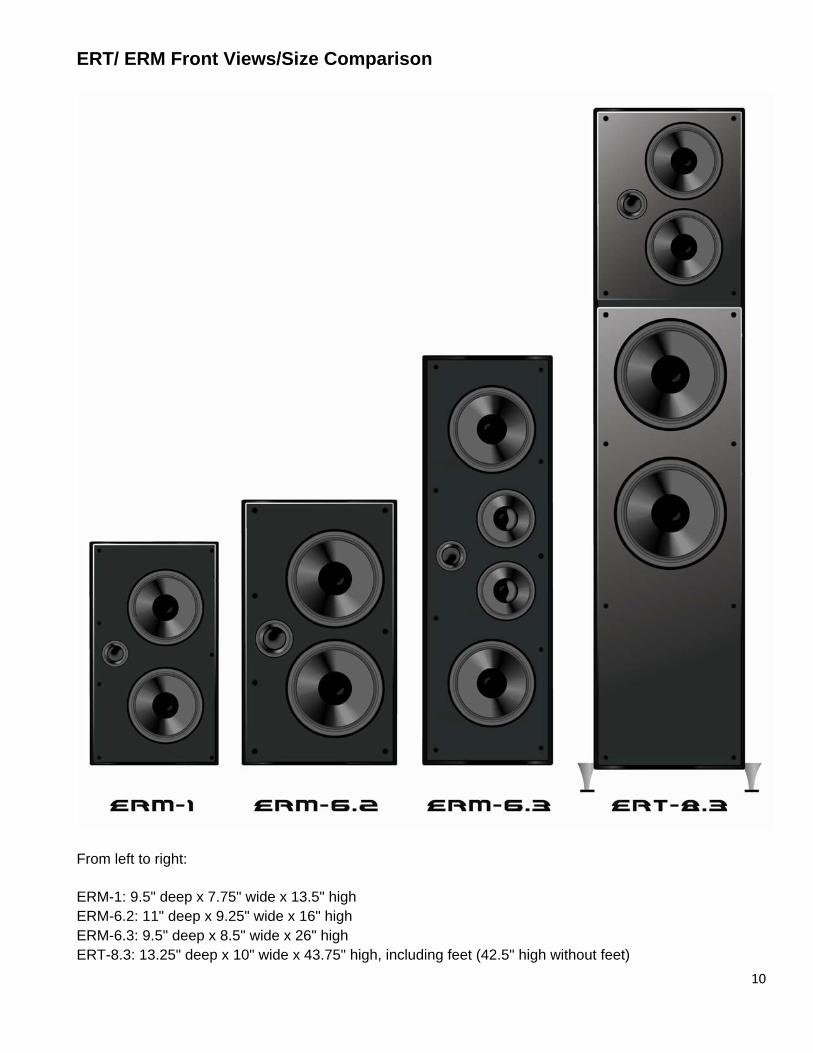
ERT/ ERM Front Views/Size Comparison
From left to right:
ERM-1: 9.5" deep x 7.75" wide x 13.5" high ERM-6.2: 11" deep x 9.25" wide x 16" high ERM-6.3: 9.5" deep x 8.5" wide x 26" high ERT-8.3: 13.25" deep x 10" wide x 43.75" high, including feet (42.5" high without feet)
10
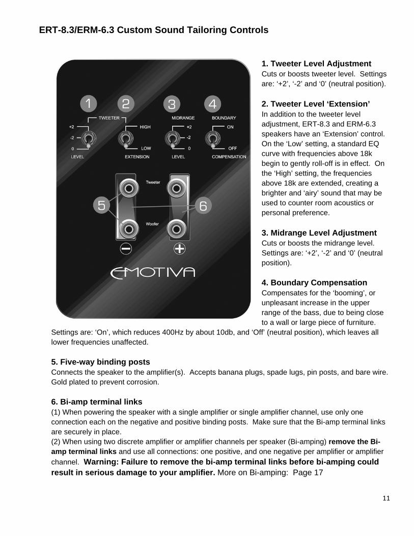
ERT-8.3/ERM-6.3 Custom Sound Tailoring Controls
1. Tweeter Level Adjustment Cuts or boosts tweeter level. Settings are: ‘+2’, ‘-2’ and ‘0’ (neutral position). 2. Tweeter Level ‘Extension’ In addition to the tweeter level adjustment, ERT-8.3 and ERM-6.3 speakers have an ‘Extension’ control. On the ‘Low’ setting, a standard EQ curve with frequencies above 18k begin to gently roll-off is in effect. On the ‘High’ setting, the frequencies above 18k are extended, creating a brighter and ‘airy’ sound that may be used to counter room acoustics or personal preference. 3. Midrange Level Adjustment Cuts or boosts the midrange level. Settings are: ‘+2’, ‘-2’ and ‘0’ (neutral position).
4. Boundary Compensation Compensates for the ‘booming’, or unpleasant increase in the upper range of the bass, due to being close to a wall or large piece of furniture.
Settings are: ‘On’, which reduces 400Hz by about 10db, and ‘Off’ (neutral position), which leaves all lower frequencies unaffected.
5. Five-way binding posts Connects the speaker to the amplifier(s). Accepts banana plugs, spade lugs, pin posts, and bare wire. Gold plated to prevent corrosion.
6. Bi-amp terminal links (1) When powering the speaker with a single amplifier or single amplifier channel, use only one connection each on the negative and positive binding posts. Make sure that the Bi-amp terminal links are securely in place. (2) When using two discrete amplifier or amplifier channels per speaker (Bi-amping) remove the Bi-amp terminal links and use all connections: one positive, and one negative per amplifier or amplifier channel. Warning: Failure to remove the bi-amp terminal links before bi-amping could result in serious damage to your amplifier. More on Bi-amping: Page 17
11
ERM-6.2/ERM-1 Custom Sound Tailoring Controls
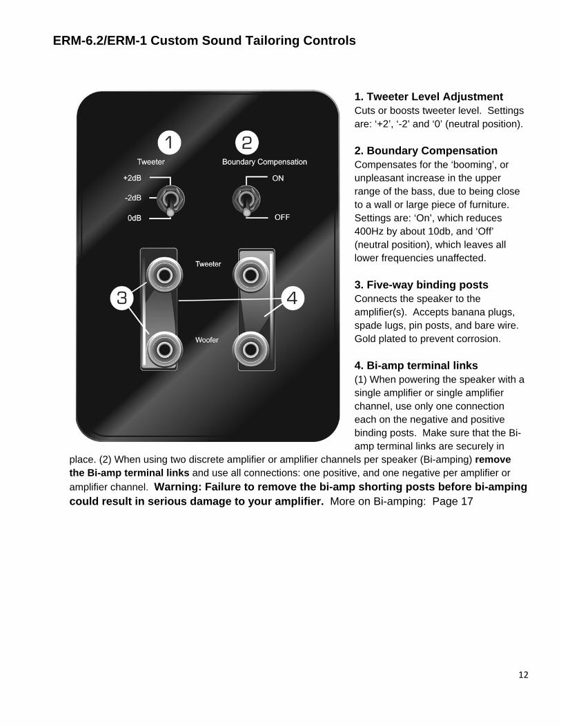
1. Tweeter Level Adjustment Cuts or boosts tweeter level. Settings are: ‘+2’, ‘-2’ and ‘0’ (neutral position).
12
2. Boundary Compensation Compensates for the ‘booming’, or unpleasant increase in the upper range of the bass, due to being close to a wall or large piece of furniture. Settings are: ‘On’, which reduces 400Hz by about 10db, and ‘Off’ (neutral position), which leaves all lower frequencies unaffected.
3. Five-way binding posts Connects the speaker to the amplifier(s). Accepts banana plugs, spade lugs, pin posts, and bare wire. Gold plated to prevent corrosion.
4. Bi-amp terminal links (1) When powering the speaker with a single amplifier or single amplifier channel, use only one connection each on the negative and positive binding posts. Make sure that the Bi-amp terminal links are securely in
place. (2) When using two discrete amplifier or amplifier channels per speaker (Bi-amping) remove the Bi-amp terminal links and use all connections: one positive, and one negative per amplifier or amplifier channel. Warning: Failure to remove the bi-amp shorting posts before bi-amping could result in serious damage to your amplifier. More on Bi-amping: Page 17
ERD-1 Front and Back Views with Expanded Control Panel
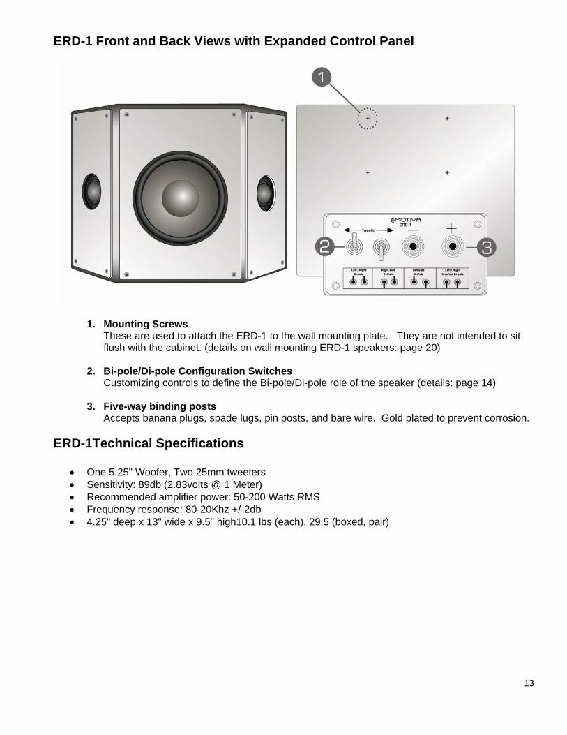
1. Mounting Screws These are used to attach the ERD-1 to the wall mounting plate. They are not intended to sit flush with the cabinet. (details on wall mounting ERD-1 speakers: page 20)
2. Bi-pole/Di-pole Configuration Switches
Customizing controls to define the Bi-pole/Di-pole role of the speaker (details: page 14)
3. Five-way binding posts Accepts banana plugs, spade lugs, pin posts, and bare wire. Gold plated to prevent corrosion.
ERD-1Technical Specifications
• One 5.25" Woofer, Two 25mm tweeters • Sensitivity: 89db (2.83volts @ 1 Meter) • Recommended amplifier power: 50-200 Watts RMS • Frequency response: 80-20Khz +/-2db • 4.25" deep x 13" wide x 9.5" high10.1 lbs (each), 29.5 (boxed, pair)
13
ERD-1 Di-pole/Bi-pole Switch Configurations
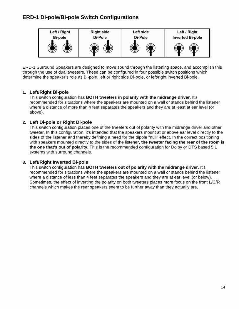
ERD-1 Surround Speakers are designed to move sound through the listening space, and accomplish this through the use of dual tweeters. These can be configured in four possible switch positions which determine the speaker’s role as Bi-pole, left or right side Di-pole, or left/right inverted Bi-pole. 1. Left/Right Bi-pole
This switch configuration has BOTH tweeters in polarity with the midrange driver. It's recommended for situations where the speakers are mounted on a wall or stands behind the listener where a distance of more than 4 feet separates the speakers and they are at least at ear level (or above).
2. Left Di-pole or Right Di-pole This switch configuration places one of the tweeters out of polarity with the midrange driver and other tweeter. In this configuration, it's intended that the speakers mount at or above ear level directly to the sides of the listener and thereby defining a need for the dipole "null" effect. In the correct positioning with speakers mounted directly to the sides of the listener, the tweeter facing the rear of the room is the one that's out of polarity. This is the recommended configuration for Dolby or DTS based 5.1 systems with surround channels.
3. Left/Right Inverted Bi-pole This switch configuration has BOTH tweeters out of polarity with the midrange driver. It's recommended for situations where the speakers are mounted on a wall or stands behind the listener where a distance of less than 4 feet separates the speakers and they are at ear level (or below). Sometimes, the effect of inverting the polarity on both tweeters places more focus on the front L/C/R channels which makes the rear speakers seem to be further away than they actually are.
14
15
Locations, Installation and Connections This section is a preliminary overview of the considerations you should observe in the installation locations and connections of your new Emotiva Loudspeakers. Observe the following precautions when choosing locations for your ERT-8.3/ERM-6.3/ERM-6.2 Speakers.
1) The ERT-8.3 speakers are intended to be the main front speakers (L/R) of your home entertainment system. They are made to be used with the adjustable 2-position silver billet aluminum outriggers for maximum stability.
2) The ERM-6.3 speakers are intended to be the main front speakers (L/C/R) of your home entertainment system.
3) The ERM-6.2 speakers are intended to be the main front speakers (L/C/R) of your home entertainment system.
4) Use appropriate oxygen free speaker cable between your receiver or amplifier and the Emotiva speakers. Observe correct polarity when making the connections at either end. If the speaker cables will be visible at any point, select insulation colors or wire management accessories that compliment the room whenever possible.
5) Carefully remove grills before installing the speakers and mount them only when installation is complete and the speakers are in a secure position. This is to minimize the chance of damage to either the speakers or faceplate of the speakers by putting pressure on the grilles.
The subsequent section on Speaker Placement Tips will also help you determine some of the ideal positioning of your new Emotiva speakers based on the configuration of your room, furniture, and other components.
Tips for Choosing Speaker Locations
Please read this section thoroughly. There are a number of ways in which it may seem aesthetically pleasing to place the speakers in a room that will ultimately result in a sound quality compromise. The placement of speakers is equally as important as the room itself. While there may be very little you can do about the room in which your home theater equipment is installed, you can choose placement of speakers within that room to maximize the sound quality of the system. Ultimately, this will give a much better result when you are enjoying your home theater components and your new Emotiva ERT/ ERM/ERD loudspeakers.
Overall, the best placement for front speakers is where the sound is directed at ear level. This means that the speakers themselves can be in positions lower (i.e. small floor standing speakers) or higher (i.e. in-wall or in-ceiling speakers) as long as the sound is “pointed” toward the listeners and preferably around ear level. This is not necessarily the case with the rear speakers or the side axis speakers. Read each of the sections carefully for the most appropriate positioning. A subwoofer is also a little challenging to install depending on the room. In multiple subwoofer installations the positioning of the woofers to the listener, as well as to each other, is critical because there can be problems with cancellation if optimum placement is not observed.
16
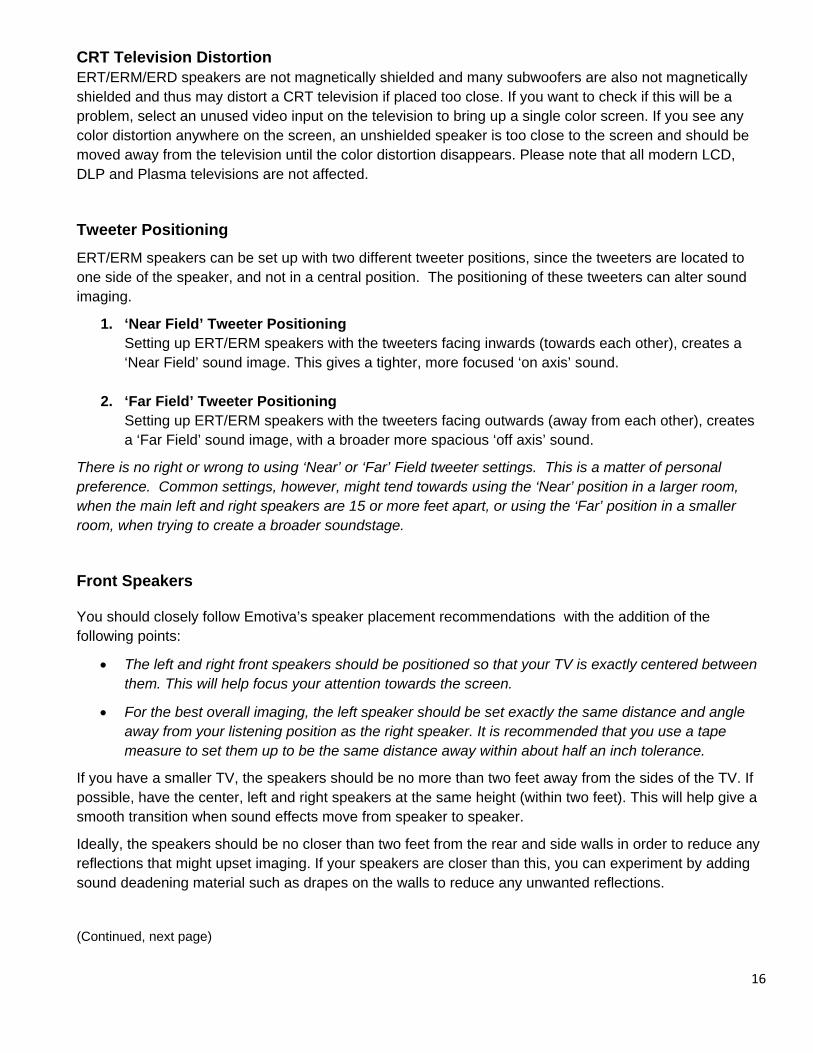
CRT Television Distortion ERT/ERM/ERD speakers are not magnetically shielded and many subwoofers are also not magnetically shielded and thus may distort a CRT television if placed too close. If you want to check if this will be a problem, select an unused video input on the television to bring up a single color screen. If you see any color distortion anywhere on the screen, an unshielded speaker is too close to the screen and should be moved away from the television until the color distortion disappears. Please note that all modern LCD, DLP and Plasma televisions are not affected.
Tweeter Positioning
ERT/ERM speakers can be set up with two different tweeter positions, since the tweeters are located to one side of the speaker, and not in a central position. The positioning of these tweeters can alter sound imaging.
1. ‘Near Field’ Tweeter Positioning Setting up ERT/ERM speakers with the tweeters facing inwards (towards each other), creates a ‘Near Field’ sound image. This gives a tighter, more focused ‘on axis’ sound.
2. ‘Far Field’ Tweeter Positioning Setting up ERT/ERM speakers with the tweeters facing outwards (away from each other), creates a ‘Far Field’ sound image, with a broader more spacious ‘off axis’ sound.
There is no right or wrong to using ‘Near’ or ‘Far’ Field tweeter settings. This is a matter of personal preference. Common settings, however, might tend towards using the ‘Near’ position in a larger room, when the main left and right speakers are 15 or more feet apart, or using the ‘Far’ position in a smaller room, when trying to create a broader soundstage.
Front Speakers
You should closely follow Emotiva’s speaker placement recommendations with the addition of the following points:
• The left and right front speakers should be positioned so that your TV is exactly centered between them. This will help focus your attention towards the screen.
• For the best overall imaging, the left speaker should be set exactly the same distance and angle away from your listening position as the right speaker. It is recommended that you use a tape measure to set them up to be the same distance away within about half an inch tolerance.
If you have a smaller TV, the speakers should be no more than two feet away from the sides of the TV. If possible, have the center, left and right speakers at the same height (within two feet). This will help give a smooth transition when sound effects move from speaker to speaker.
Ideally, the speakers should be no closer than two feet from the rear and side walls in order to reduce any reflections that might upset imaging. If your speakers are closer than this, you can experiment by adding sound deadening material such as drapes on the walls to reduce any unwanted reflections.
(Continued, next page)
17
Center Speaker
Most movie dialogue is a discrete multi-channel format that will come from the center speaker, so careful positioning is an important part of a good home theater system. Your eyes and ears should focus your attention towards the center of the screen.
The center speaker can sit on top or directly underneath the TV, as long as it is located on the center line and not off to one side. Ideally, you would try to maintain a deviation from the center line of the speakers of less than 12”. This means the center speaker will not be lower or higher than 12” to the center measurement of the LEFT and RIGHT MAIN speaker center measurements.
Position the front face of the speaker close to the front edge of the TV cabinet. (The sound waves may otherwise reflect off the top of the TV cabinet and distort the center imaging). Some systems use two center speakers, one on either side of the TV. As they are in mono, the result is a sound image that is positioned exactly at the screen center. This is an acceptable approach where the room is wider and the LEFT/RIGHT speakers are further out.
Tweeter position: To get the most out of your system, Emotiva recommends that you position your center channel speaker with the tweeter facing down (towards the floor) when the speaker is mounted above your TV, and facing up (towards the ceiling) when the speaker is placed beneath the TV.
Note: Speakers are not magnetically shielded and many subwoofers are also not magnetically shielded and thus may distort a CRT television if placed too close. If you want to check if this will be a problem, select an unused video input on the television to bring up a single color screen. If you see any color distortion anywhere on the screen, an unshielded speaker is too close to the screen and should be moved away from the television until the color distortion disappears. Please note that all modern LCD, DLP and Plasma televisions are not affected.
Side-Axis Speakers
Some preamplifier processors feature side-axis channels which are matrixed and derived from the left and right front channels, so they are available in stereo as well as surround modes. If available as a feature, the processor should have a set-up menu to turn the SIDE-AXIS channels ON or OFF. Many Emotiva processors have this feature.
Typical placement of side-axis speakers is depicted by the speakers that appear to be "suspended" where walls are in the room. Wherever you position them, place these speakers along the side walls, close to the fronts. You can also angle them in towards your listening position for better results. Using a specific surround speaker (such as the ERD-1) for side axis speakers is especially beneficial because you can configure the speaker to be a dipole or bi-pole configuration depending on its location. Try a dipole configuration initially to see how you like it.

18
Surround Speakers
In a surround speaker setup that closely follows Dolby and DTS recommendations, the surrounds should be mounted on the wall directly to the right and left sides of the seated position OR on stands that are elevated at least to ear height. Higher than ear height is actually preferred. In that position, if the listener points their arms straight out to the sides, then they would be pointing to where the surrounds should be mounted.
In this configuration (the ERD-1) should be set in a dipole configuration. In dipole configurations, the sound radiates forwards and backwards and has a quiet null zone (the "apex" of the triangular shape) which is directed towards the listener. The overall effect is that you cannot hear the direct sound from the surround speakers because they don't directly radiate into the listener's axis.
Should the surround speaker locations be chosen to be behind the listeners, Emotiva recommends a bi-pole setting to initially evaluate the performance but eliminate the null zone effect. These suggested configurations are the norm, but given personal listening taste, odd room configurations, etc., it is possible to configure the speakers in a variety of ways to suit the listening taste of the individual.
Surround Back Speakers
Many preamplifier processors feature additional outputs for surround back speakers. These create a wonderful sense of realism in surround effects during playback of Dolby Digital EX, Dolby Digital Pro Logic IIx and DTS-ES. Often when the system has surround speakers mounted to the sides of the listeners, the surround back speakers are mounted or positioned behind the listeners.
Ideally, "Surround" and "Surround Back" speakers should be of the same make and model, and fitted at similar heights to produce a smooth continuous sound field. In an ERD-1 surround back application where they are mounted to a wall behind the listeners though, select the Left /Right Bi-pole switch setting initially to get started. This will eliminate the null zone that a dipole configuration would produce in that positioning.
19
Installing the Speakers
Positioning Left and right front speakers should be positioned so that your TV is exactly centered between them. This will help focus your attention towards the screen.
For the best overall imaging, the left speaker should be set exactly the same distance and angle away from your listening position as the right speaker. It is recommended that you use a tape measure to set them up to be the same distance away within about half an inch tolerance.
If you have a smaller TV, the speakers should be no more than two feet away from the sides of the TV. If possible, have the center, left and right speakers at the same height (within two feet). This will help give a smooth transition when sound effects move from speaker to speaker.
Ideally, the speakers should be no closer than two feet from the rear and side walls in order to reduce any reflections that might upset imaging. If your speakers are closer than this, you can experiment by adding sound deadening material such as drapes on the walls to reduce any unwanted reflections.
ERT-8.3 Installation
• Outriggers ERT-8.3 speakers have adjustable brushed aluminum outriggers for maximum stability. During shipping, they are set to the ‘in’ position. To adjust the outriggers to the ‘out’ position, gently place each ERT-8.3 on its back, and remove the screws holding the outriggers in place. Once the screws are removed, slide the outriggers outward, lining up the drilled holes in the outriggers with the threaded inserts in the bottom of the speaker cabinet and carefully replace and tighten the screws. Do not over-tighten.
• Outrigger Cones (feet) Each ERT-8.3 comes with four brushed aluminum cones (or feet) that attach to the outriggers. These are located inside a cutout area in the top or bottom end caps of the ERT-8.3 packaging. Peel away the clear taps covering the cutout area and remove the cones, which are in individual plastic bags. Each cone is capped with a piece of felt on the narrow end, and topped with a screw at the wider end. Install the cones by carefully threading them into the screw inserts on the outer edge of the outriggers. The cones should fit snugly inside the circular recessed area around the screw inserts.
ERM Bookshelf Installations
If you are placing ERM speakers on a bookshelf or within a cabinet, allow room to the sides to eliminate unnecessary reflections and place the speaker close to the edge. In most cases you will select the Boundary Compensation switch to "ON"
When installing in bookshelves or other cavities with near field boundaries, set the Boundary Compensation switch to “ON”.
ERM Stand Mounting
If you are placing your ERM speakers on stands, be sure to place them at equal distances from the listening position with respect to the left and right sides. This will ensure the most accurate stereo or multichannel reproduction. Also, ensure the footprint of the speaker is well supported by the stand. The Boundary Compensation switch position on the ERM speaker will depend on the proximity to other walls or large furniture.
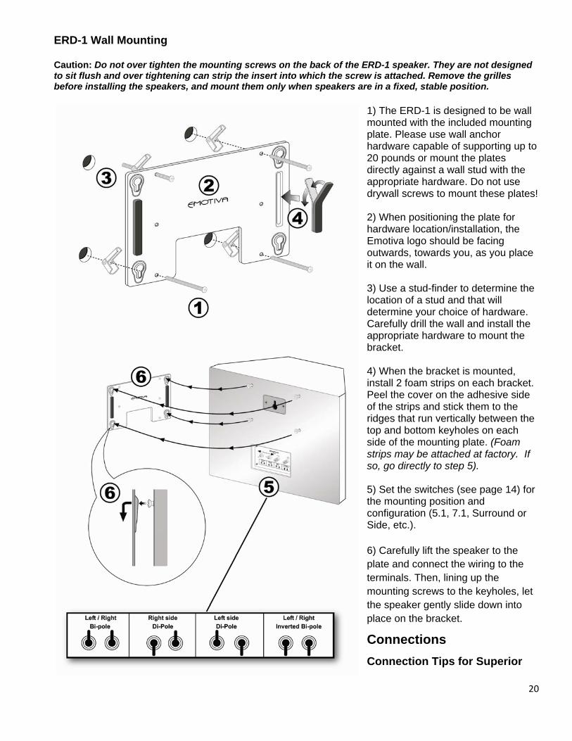
ERD-1 Wall Mounting
Caution: Do not over tighten the mounting screws on the back of the ERD-1 speaker. They are not designed to sit flush and over tightening can strip the insert into which the screw is attached. Remove the grilles before installing the speakers, and mount them only when speakers are in a fixed, stable position.
20
lates!
) When positioning the plate for
lace
) Use a stud-finder to determine the
are.
) When the bracket is mounted, et.
e
f
) Set the switches (see page 14) for
ound or
) Carefully lift the speaker to the
es, let
Connections
1) The ERD-1 is designed to be wall mounted with the included mounting plate. Please use wall anchor hardware capable of supporting up to 20 pounds or mount the plates directly against a wall stud with the appropriate hardware. Do not use drywall screws to mount these p 2hardware location/installation, the Emotiva logo should be facing outwards, towards you, as you pit on the wall. 3location of a stud and that will determine your choice of hardwCarefully drill the wall and install the appropriate hardware to mount the bracket. 4install 2 foam strips on each brackPeel the cover on the adhesive side of the strips and stick them to the ridges that run vertically between thtop and bottom keyholes on each side of the mounting plate. (Foam strips may be attached at factory. Iso, go directly to step 5). 5the mounting position and configuration (5.1, 7.1, SurrSide, etc.). 6plate and connect the wiring to the terminals. Then, lining up the mounting screws to the keyholthe speaker gently slide down into place on the bracket.
Connection Tips for Superior
Sound
Before setting up your home entertainment system, please consider the following:
• Whenever possible, route the power cords away from the signal cables or speaker wires to prevent any hum or interference heard in the speakers.
• Many audiophile signal and speaker cables are intended to be hooked up in one direction. If this is the case, the cables will be marked with arrows the direction of signal flow.
• ALWAYS observe the correct polarity for speaker wiring, both at the amplifier output and at the speaker itself. This is a key point to great sound.
• Should you have any questions about connection or configuration of any Emotiva products, visit the SUPPORT section of the Emotiva website or call us directly at (877) EMO-TECH
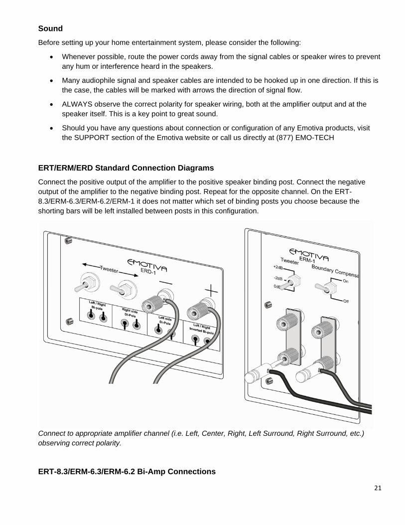
ERT/ERM/ERD Standard Connection Diagrams
Connect the positive output of the amplifier to the positive speaker binding post. Connect the negative output of the amplifier to the negative binding post. Repeat for the opposite channel. On the ERT-8.3/ERM-6.3/ERM-6.2/ERM-1 it does not matter which set of binding posts you choose because the shorting bars will be left installed between posts in this configuration.
Connect to appropriate amplifier channel (i.e. Left, Center, Right, Left Surround, Right Surround, etc.) observing correct polarity.
ERT-8.3/ERM-6.3/ERM-6.2 Bi-Amp Connections
21
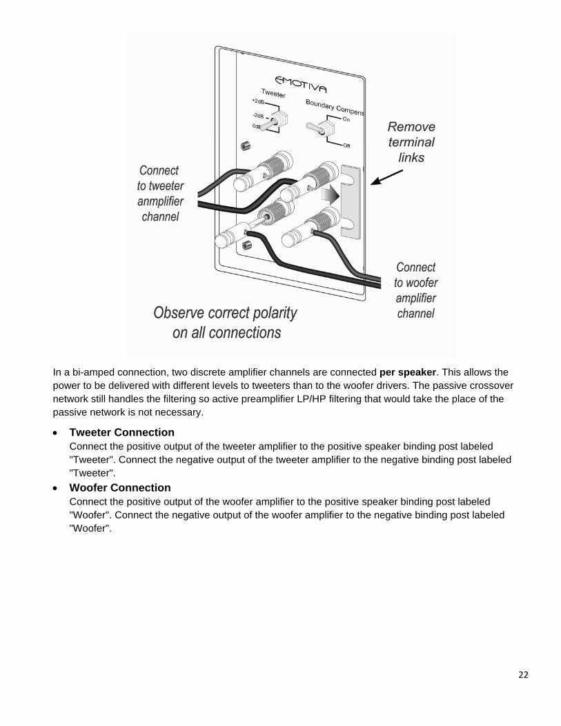
In a bi-amped connection, two discrete amplifier channels are connected per speaker. This allows the power to be delivered with different levels to tweeters than to the woofer drivers. The passive crossover network still handles the filtering so active preamplifier LP/HP filtering that would take the place of the passive network is not necessary.
• Tweeter Connection Connect the positive output of the tweeter amplifier to the positive speaker binding post labeled "Tweeter". Connect the negative output of the tweeter amplifier to the negative binding post labeled "Tweeter".
• Woofer Connection Connect the positive output of the woofer amplifier to the positive speaker binding post labeled "Woofer". Connect the negative output of the woofer amplifier to the negative binding post labeled "Woofer".
22
23
LIMITED WARRANTY Emotiva Audio is proud to design and manufacture quality products for the home audio and home theater enthusiast. Your ERT/ ERM/ ERD Speakers have been crafted to perform flawlessly for many years. As a result of this quality and craftsmanship, Emotiva offers the following warranty to owners of the ERT/ ERM/ ERD Speakers.
Emotiva Audio warrants ERT/ ERM/ ERD Speakers to be free from defects in materials and workmanship for a period of five years from the original date of purchase. The following items are excluded from, or will void this warranty coverage:
1) Damage to ERT/ ERM/ ERD Speakers caused during shipment and handling. (If you receive an item that you believe to have been damaged during shipment, please contact Emotiva immediately. Phone: 877-EMO-Tech (877-366-8324) / Email: [email protected]
2) Damage to ERT/ ERM/ ERD Speakers caused by accident, misuse or abusive operation contrary to the instructions specified within this manual.
3) Damage to ERT/ ERM/ ERD Speakers resulting from a modification of, or attempted repair by any person or company not authorized by Emotiva.
4) Emotiva does not assume liability for loss of use, or damage to, associated or connected equipment.
Service Assistance for ERT/ERM /ERD Loudspeakers Please note that BEFORE sending your ERT/ ERM/ ERD Speakers in for repair you MUST call Emotiva and obtain a return authorization (RMA) number. Before contacting Emotiva to begin the RMA process, please have as detailed a description of the problem(s) you are experiencing and the conditions under which the problem(s) occur. Many instances of perceived failure are simple operational and setup mistakes and Emotiva is happy to assist you however possible. Please call 877-EMO-Tech (877-366-8324) Email: [email protected]
Once you have obtained the RMA number, you must print this clearly on the outside of the box so it will be possible to determine from whom the speaker(s) came once the package arrives. Parcels arriving without an RMA numbers will be refused and returned freight collect.
Please send your repairs with RMA to:
Emotiva Audio Corp. Attn.: Repair Department 131 Southeast Parkway Court Franklin, TN 37064 Reference – (Put your RMA number in this spot.) 877-EMO-Tech (877-366-8324) / Email: [email protected]

24
Emotiva Disclosure Copyright 2009 Emotiva All Rights Reserved. Emotiva reserves the right to make improvements to its products at any time. Therefore, the specifications of the product and the specific details of this manual are subject to change at any time. Emotiva and the Emotiva "E" are registered trademarks of Emotiva Audio Corporation