Embed Size (px)
Citation preview
StandardDivisionBridge
of this standard to other for
mats or for in
correct results or da
mages resultin
g fro
m its use.
kin
d is
made by Tx
DO
T for any purpose
whatsoever. Tx
DO
T assu
mes no responsibilit
y for the conversio
n
The use of this standard is governed by the "T
exas E
ngin
eerin
g Practic
e
Act".
No
warranty of any
DIS
CL
AI
ME
R:
FILE:
DA
TE:
SHEET 1 OF 3
DN: CK: DW: CK:FILE:
JOB
COUNTY
SECT
DIST
REVISIONS
TxDOT TxDOT TxDOT TxDOT
HIGHWAY
SHEET NO.
C TxDOT
CONT
sgebste1.dgn
January 2015
STEEL GIRDERS AND BEAMS
BEARING DETAILS
ELASTOMERIC
SGEB
Pad width
S
Bolts
Anchor
" Dia211
Sole Plate width
"41
Typ
Proj
Min
Em
bed
Min
1'-
3"
Pipe Sleeve
" Std43x 5
" Dia211
template
tack weld to
Heavy Hex Nut,
and Washer
Heavy Hex Nut
L BrgC
CH
at L Brg
C
or stem
Face of Bkwl
L Cap,
Sole Plate length
" Min21
C
or stem
Face of Bkwl
L Cap,
See Span details
for dimension
Pad length
CL Girder
or Corbel
Face of Cap
CL Brg
Sho
win
g E
F Bearin
gS
ho
win
g E
E Bearin
g
1
2
(Expansio
n)
(Fix
ed)
Fla
nge
Width
5Edge of Brg Seat
3
4
5
"41
CL Girder
FRONT ELEVATION SIDE ELEVATIONPLAN
Brg Seat
Top of
EF Brgs
" Dia Holes,832
EE Brgs
" Slots,43" x 4 8
32 Brg Seat
Edge of5
not shown for clarity
Pipe sleeves, washers and nuts
x 4)41(PL
Template
(Typ)
2"
8"
at bearing locations.
See span details for beam grade (slope)
is "S" + 8".
Min Bearing Seat width, normal to girder,
Locate permanent mark here.
Locate "Bearing Type" identification here.
(actual exp length/max exp length).
Min DL can be reduced by the ratio of
Applicable to EE bearings only.
6
Paid for at unit price bid for "Elastomeric Bearing" as per Item 434.
DURO 50
T
"4
1"
41
"8
36 at
Pad length = 9"
match beam grade
Bevel top surface to
Sole Plate length = 11"
H
steel laminates
7 ~ 0.105" thickCL Brg
3
44
2"
Sole P
L
at L Brg
C
layers
Elastomer
Vulcanize Sole Plate to elastomer.
6
BEARING DETAIL
ELASTOMERIC
TYPE EE & EF
END FIXED (EF) AND EXPANSION (EE) BEARINGS7
in
Neoprene Pad
Type
Bearing
kip ft
Sole Plate Flange Width Reactions
Width Length Min MaxMin DL Max DL Total
MaxH S TWidth Length
in in in in in in in in kip kip
TABLE OF END BEARING DESIGNS
2
1
1
Length
Expansion
Max
Steel Template
Permanent
Steel Template
Temporary
template
permanent
nut to lower
of tack welding
be used in lieu
Double nuts may
ANCHOR BOLT SETTING DETAIL
shown to hold template in place.
template) and provide two nuts as
Use upper template (same size as lower
L BrgC
approved by the Engineer.
clamps or other methods
prior to welding using
Sole Plate and Girder
Remove gaps between
GIRDER TO SOLE PLATE WELD DETAIL
BOLT SETTING DETAIL
OPTIONAL ANCHOR
present after bearing seat construction.
ensure minimum anchor bolt projection will be
If not casting bearing seat integral with cap,
Min E
mbed
els
ew
here
detailed
Min Proj
els
ew
here
detailed
Bolt Dia plus 3"
Max Dia is
Size is detailed elsewhere.
Provide fully-threaded rod.
Slope to drain
Top of cap
Form hole
Grout
Brg Seat
Top of
~
8
7
8
Applies to all bearings on this standard.
movement.
restrain temperature-induced lateral
The anchor bolts are not designed to
use with bridges over 100 ft wide.
These bearings are not intended for
material before placement of bearings.
are clean and free of all loose
wood float bearing seat surfaces that
All bearings on this standard require
41.0 3.49 26 36 142 355 443 250 5.5 11 46.5 9 36EE9 or EF9
39.0 3.49 24 34 134 331 414 250 5.5 11 44.5 9 34EE8 or EF8
37.0 3.49 22 32 126 307 384 250 5.5 11 42.5 9 32EE7 or EF7
35.0 3.49 20 30 118 284 355 250 5.5 11 40.5 9 30EE6 or EF6
32.0 3.49 17 27 106 249 312 250 5.5 11 37.5 9 27EE5 or EF5
29.0 3.49 14 24 95 215 269 250 5.5 11 34.5 9 24EE4 or EF4
26.0 3.49 11 21 83 181 226 250 5.5 11 31.5 9 21EE3 or EF3
23.0 3.49 10 18 71 148 185 250 5.5 11 28.5 9 18EE2 or EF2
20.0 3.49 10 15 59 115 144 250 5.5 11 25.5 9 15EE1 or EF1
placement, before initial set.
if necessary, anchor bolt location immediately after concrete
Applies to all bearings on this standard. Verify and correct,
girders and sole plates are anticipated under steel dead load only.
Applies to all end bearings on this standard. Small gaps between
GENERAL NOTES:
MATERIAL NOTES:
using Type VIII epoxy. Clean holes before filling.
strength. Void may also be filled with epoxy grout
DMS-4675 and capable of 4,000 psi compressive
Fill void with a pre-qualified grout conforming to
Do not drill hole.
use PVC or other smooth plastic or steel duct.
corrugated metal post-tensioning duct. Do not
requirements of Item 426.2.2 or galvanized
Form hole with either plastic duct meeting the
Install anchor bolt nuts finger-tight or loosely snug.
total.
"161parallel to the theoretical top surface can not exceed
" +/-, except the variation from a plane161drawings is
structure. Thickness tolerance variation from the shop
centerline of bearing and slope of the girder in the finished
" based on required thickness at161plates to the nearest
Shop drawings for approval are required. Dimension sole
be provided to the Engineer.
with the bearing layout. A copy of the bearing layout is to
bearings. Permanently mark each bearing in accordance
layout which identifies location and orientation of all
The bearing fabricator is required to develop a bearing
See span details for bearing type and location.
uplift.
girders. None of the bearings shown are designed to resist
with continuous and simple span rolled beams and plate
The bearings shown on this standard are intended for use
steel for sole plates must conform to ASTM A 588.
to ASTM A 36 or A 588. For unpainted (weathering) bridges,
For painted bridges, steel for sole plates must conform
sleeves as per Item 445, "Galvanizing".
end plus 6" Min), nuts not embedded in concrete, and pipe
A 500 Grade B. Hot-dip galvanize all anchor bolts (exposed
conform to the requirements of ASTM A 53 Grade B or
Washers must conform to ASTM F 436. Pipe sleeves must
Grade DH, heavy hex or A194 Grade 2H, heavy hex.
ASTM A 193 Grade B7. Nuts must conform to ASTM A 563
Anchor bolts must conform to ASTM F 1554 Grade 105 or
01-16: Max DL for ES bearings.
StandardDivisionBridge
of this standard to other for
mats or for in
correct results or da
mages resultin
g fro
m its use.
kin
d is
made by Tx
DO
T for any purpose
whatsoever. Tx
DO
T assu
mes no responsibilit
y for the conversio
n
The use of this standard is governed by the "T
exas E
ngin
eerin
g Practic
e
Act".
No
warranty of any
DIS
CL
AI
ME
R:
FILE:
DA
TE:
SHEET 2 OF 3
DN: CK: DW: CK:FILE:
JOB
COUNTY
SECT
DIST
REVISIONS
TxDOT TxDOT TxDOT TxDOT
HIGHWAY
SHEET NO.
C TxDOT
CONT
sgebste1.dgn
January 2015
STEEL GIRDERS AND BEAMS
BEARING DETAILS
ELASTOMERIC
SGEB
Type
Bearing
"431 " Dia4
32 1'- 6"
F4 thru F6 "412 " Dia4
13 2'- 0"
F7 thru F9 "212 " Dia8
73 2'- 1"
E1 thru E3 "431 1'- 6"
E4 thru E6 "412 2'- 0"
E7 thru E9 "212 2'- 1"
"219
"21" x 4 4
32
"41" x 6 4
13
" x 7"873
"219
Hole Size
Sole Plate Anchor Bolt
Embed ProjDia
Bolt
Anchor
DURO 50
H
T
"4
1"
41
steel laminates
0.105" thick
Pad width
Typ
"41
CL Girder
Sole Plate width
Min
Em
bed
Anchor B
olt
S
Sole Plate length
Cap
Face of
Pad length
Cap
Face of
L GirderC
F1 thru F3
Sole Plate length
Pad length
"41
Sho
win
g F Bearin
gS
ho
win
g E Bearin
g
(Expansio
n)
(Fix
ed)
Fla
nge
Width
Min Proj
Brg Seat
Top of
FRONT ELEVATIONPLAN
match beam grade
Bevel top surface to
3
4
CL Brg
2"
Sole P
L
at L Brg
C
4
"85" x 6 2
12
"832" x 5
"413" x 7
"832" x 5
"85" x 6 2
12
"413" x 7
2
3
4
5
6
5Brg Seat
Edge of
5Brg Seat
Edge of
CL Brg
hole size
Bolt Dimensions for
See Table of Anchor
slotted hole size
Bolt Dimensions for
See Table of Anchor
CL Cap
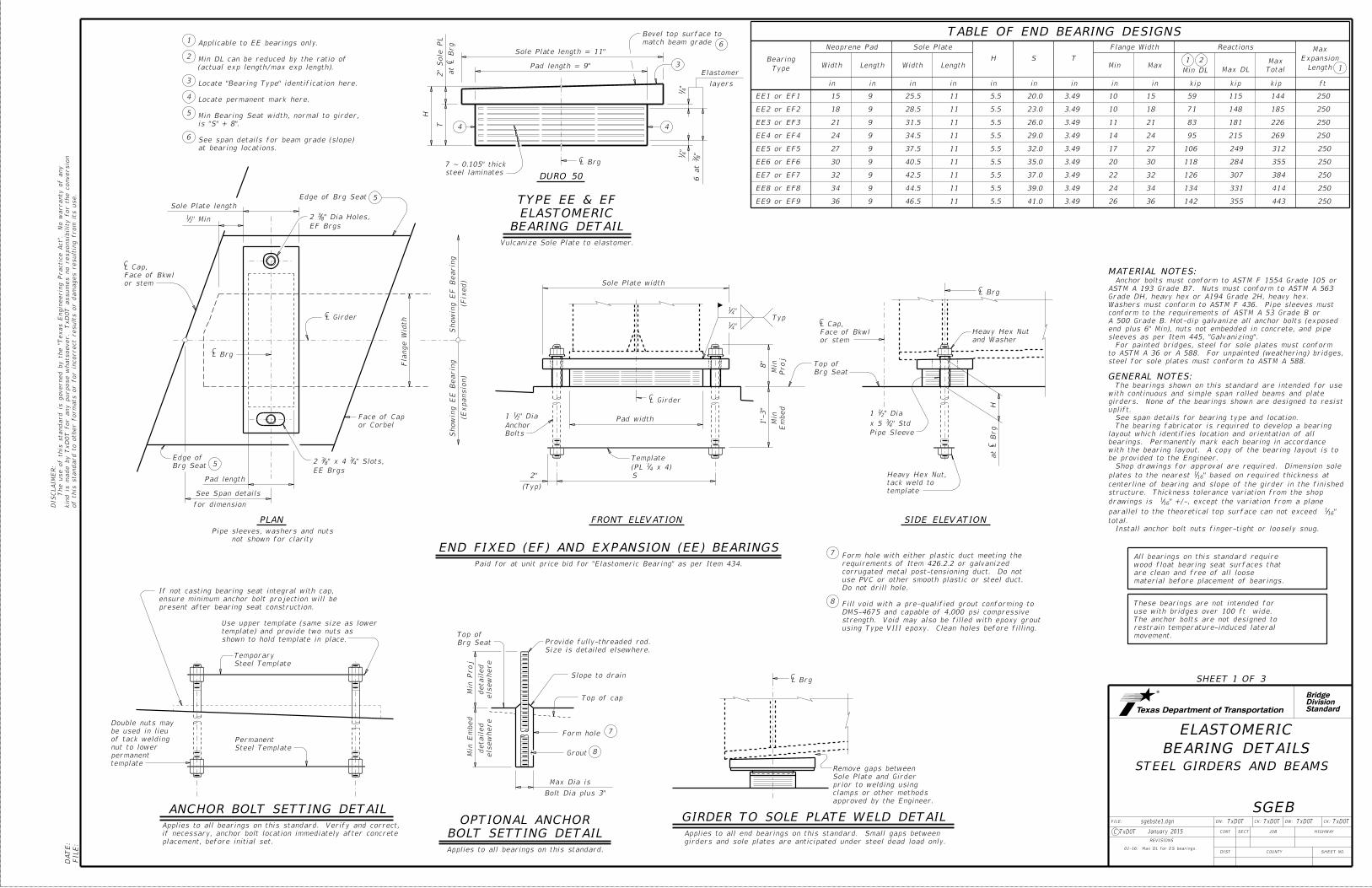
Paid for at unit price bid for "Elastomeric Bearing" as per Item 434.
not shown for clarity
Pipe sleeves, washers and nuts
(Dia x Length)
Size
Pipe Sleeve
Elastomer
layers
TYPE E & F ELASTOMERIC BEARING DETAIL
8"
"2110
8"
"2110
(Typ)
"412
)21 x 4 4
1(PL
Template
FOR TYPE E AND F BEARINGS
TABLE OF ANCHOR BOLT DIMENSIONS
Applicable to E bearings only.
at bearing locations.
See span details for beam grade (slope)
is "S" + 8".
Min Bearing Seat width, normal to girder,
Locate permanent mark here.
Locate "Bearing Type" identification here.
(actual exp length/max exp length).
Min DL can be reduced by the ratio of
9
6
INTERIOR FIXED (F) AND EXPANSION (E) BEARINGS
Vulcanize Sole Plate to elastomer
and washer
Heavy Hex Nut
L BrgC
HC
at L Brg
template
tack weld to
Heavy Hex Nut,
Pipe Sleeve
Standard
SIDE ELEVATION
in
Neoprene Pad
Type
Bearing
kip ft
Sole Plate Flange Width Reactions
Width Length Min MaxMin DL Max DL Total
MaxH S TWidth Length
in in in in in in in in kip kip
29
TABLE OF INTERIOR BEARING DESIGNS
9Length
Expansion
Max
" F1/E
1 thru F3/E
34
17 at
" F4/E
4 thru F6/E
68
38 at
" F7/E
7 thru F9/E
98
39 at
16 52.0 18 6.9 43.0 4.93 23 36 252 691 864 355 36 E9 or F9
16 50.0 18 6.9 41.0 4.93 21 34 238 653 816 355 34 E8 or F8
16 48.0 18 6.9 39.0 4.93 19 32 224 614 768 355 32 E7 or F7
14 44.5 16 6.4 36.5 4.45 18 30 184 504 630 321 30 E6 or F6
14 41.5 16 6.4 33.5 4.45 15 27 165 454 567 321 27 E5 or F5
14 38.5 16 6.4 30.5 4.45 12 24 147 403 504 321 24 E4 or F4
10 33.0 12 5.1 26.5 3.09 11 21 92 252 315 206 21 E3 or F3
10 30.0 12 5.1 23.5 3.09 10 18 79 216 270 206 18 E2 or F2
10 27.0 12 5.1 20.5 3.09 10 15 66 180 225 206 15 E1 or F1
01-16: Max DL for ES bearings.
StandardDivisionBridge
of this standard to other for
mats or for in
correct results or da
mages resultin
g fro
m its use.
kin
d is
made by Tx
DO
T for any purpose
whatsoever. Tx
DO
T assu
mes no responsibilit
y for the conversio
n
The use of this standard is governed by the "T
exas E
ngin
eerin
g Practic
e
Act".
No
warranty of any
DIS
CL
AI
ME
R:
FILE:
DA
TE:
SHEET 3 OF 3
DN: CK: DW: CK:FILE:
JOB
COUNTY
SECT
DIST
REVISIONS
TxDOT TxDOT TxDOT TxDOT
HIGHWAY
SHEET NO.
C TxDOT
CONT
sgebste1.dgn
January 2015
STEEL GIRDERS AND BEAMS
BEARING DETAILS
ELASTOMERIC
SGEB
Typ
"41
Sole Plate width
Bolts
Anchor
" Dia211
Proj
Min
Em
bed
Min
1'-
3"
Pad width
L BrgC
Pipe Sleeve
" Std43x 5
" Dia211
template
tack weld to
Heavy Hex Nut,
HC
at L Brg
(Typ)
Brg Seat
Edge of Pad length
See Span details
for dimension
C
or stem
Face of Bkwl
L Cap,
" Min21
"43 "4
3
Sole Plate length
" Slots21" x 7 8
32 steel
stainless
Edge of
or Corbel
Face of Cap
"4
34
"4
34
S
5
"41
CL Girder
C
or stem
Face of Bkwl
L Cap,
steel
stainle
ss
Edge of
Fla
nge
Width
3
4
5
10
11
Detail "A"
See
Brg Seat
Top of
FRONT ELEVATION SIDE ELEVATIONPLAN
CL Girder
"211'-3
Stainless Steel
CL Brg
1'-5"
not shown for clarity
Pipe sleeves, washers and nuts
8"
x 4)41(PL
Template
(Typ)
2"
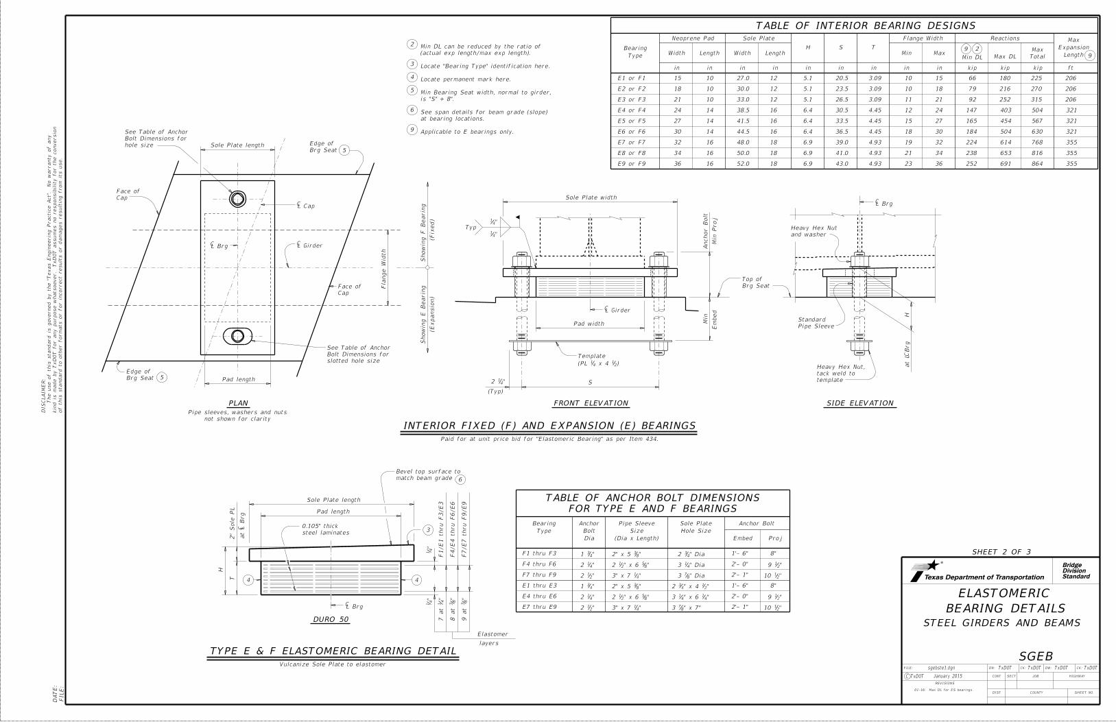
Paid for at unit price bid for "Sliding Elastomeric Bearing" as per Item 434.
6
END SLIDING (ES) EXPANSION BEARINGS
and Washer
Heavy Hex Nut
in
Neoprene Pad
Type
Bearing
ft
Sole Plate Flange Width Reactions
Width Length Min MaxMax DL Total
MaxH S TWidth Length
in in in in in in in in kip kip
TABLE OF END SLIDING BEARING DESIGNS
Length
Expansion
Max
DURO 70
T
"4
1
"8
35 at
Pad length = 9"
" Typ21 " PTFE4
1
"8
1"
81 ~
Edge of PTFE
1"
" PL21steel
" in81recessed
" PTFE sheet,41
"21
Typ
Pad
welded to Sole PL
" stainless steel,163
C
DETAIL "A"
(2" thick at L Brg)
Sole Plate
10
11
H
CL Brg
10
Sole Plate length = 17"
44
3
match beam grade
Bevel top surface to
2"
Sole P
L
at L Brg
C
steel laminates
5 ~ 0.105" thick
"16
3
Steel
Stainle
ss
steel
stainless
Edge of
Elastomer
layers
" bevel, all around81
TYPE ES ELASTOMERIC BEARING DETAIL
vulcanized to pad
" steel PL21
" P
L2
1
11
6
ES9 36 9 46.5 17 5.5 41.0 2.65 26 36 259 486 500
ES8 34 9 44.5 17 5.5 39.0 2.65 24 34 245 459 500
ES7 32 9 42.5 17 5.5 37.0 2.65 22 32 230 432 500
ES6 30 9 40.5 17 5.5 35.0 2.65 20 30 216 405 500
ES5 27 9 37.5 17 5.5 32.0 2.65 17 27 194 365 500
ES4 24 9 34.5 17 5.5 29.0 2.65 14 24 173 324 500
ES3 21 9 31.5 17 5.5 26.0 2.65 11 21 151 284 500
ES2 18 9 28.5 17 5.5 23.0 2.65 10 18 130 243 500
ES1 15 9 25.5 17 5.5 20.0 2.65 10 15 108 203 500
01-16: Max DL for ES bearings.
No paint is permitted in recess or on PTFE.
shop) with System II in accordance with Item 446.
Vulcanize plate to elastomer. Paint plate (in the
" plate must conform to ASTM A 36.21Steel for
" plate with an approved adhesive.21Bond PTFE to
at bearing locations.
See span details for beam grade (slope)
is "S" + 8".
Min Bearing Seat width, normal to girder,
Locate permanent mark here.
Locate "Bearing Type" identification here.