Embed Size (px)
Citation preview

Hydraulic transport considerations for high density thickened copper tailings at Southern Peru Copper Corporation A J C Paterson Paterson & Cooke Consulting Engineers (Pty) Ltd, Cape Town, South Africa J R G Williamson Knight Piésold Consulting, Johannesburg, South Africa U Oliveros Salas Southern Peru Copper Corporation, Toquepala, Peru
ABSTRACT
Many high Andean mines in South America utilise a combination of canals and pipelines to transport tailings and concentrate slurries by gravity. These mining operations are considering implementing thickened or paste tailings technology as a means to reduce water consumption as resources are scarce. As the solids concentration increases many of the tailings exhibit non-Newtonian properties that significantly affect the transport capacity of the canals and pipelines.
The paper presents a summary of the hydraulic transport analyses completed on the influence of rheology and slurry solids concentration for the proposed thickened tailings disposal system for Southern Peru Copper Corporation. The general implications of increasing solids concentration of high capacity canal and pipeline systems are discussed.
1 INTRODUCTION
The extensive mining operations at Toquepala and Cuajone Mines in southern Peru generate approximately 60 000 and 87 000 tonnes of dry tailings per day. The tailings are thickened at the mine sites to 60% by mass and flow from the mines to the tailings facility via a series of concrete canals and dry river valleys under gravity. The elevation difference between the mines and the tailings impoundment is more than 2 000 m and it is not economically viable to pump the water recovered from the tailings impoundment back to the mines. It would seem obvious that to improve water usage the mine tailings should be thickened further at the mine site, however before doing so there are several important factors to consider:
(i) The effect of increased solids concentration on slurry rheology.
(ii) The effect of rheology on the process, including thickening and transporting the high concentration slurry, especially in the existing low gradient lined canals.
(iii) The current tailings deposition site and placement techniques must be re-evaluated and designed to accommodate high solids concentration slurry.

The mine considered alternative tailings deposition techniques and sites and identified an area known as the Pampa Purgatorio as being most suited to the thickened tailings disposal concept pioneered by Robinsky(1). In 2002 a contract was awarded to Knight Piésold Consulting (Peru), in association with Knight Piésold South Africa and Paterson & Cooke Consulting Engineers (Pty) Ltd to investigate the feasibility of using the Pampa Purgatoria for the disposal of thickened tailings from Toquepala and Cuajone mines for their remaining life of mine until 2036.
The feasibility study included extensive site investigations, laboratory and pilot plant test work to evaluate the tailings properties. Extensive process alternatives were considered and a site specific tailings disposal and placement technique was developed to meet the site storage requirements(2). The tailings transport system analysis is presented below.
2 SLURRY TEST WORK
2.1 Slurries evaluated Slurries from the different mine sites gravitate via separate canals and converge into a single mixed tailings stream that flows to the existing tailings facility. The rheology of the different slurries was determined during the early stages of the study using samples collected at the mine site and shipped to the laboratory. Additional rheological data was obtained from freshly thickened samples during comprehensive pilot plant trials.
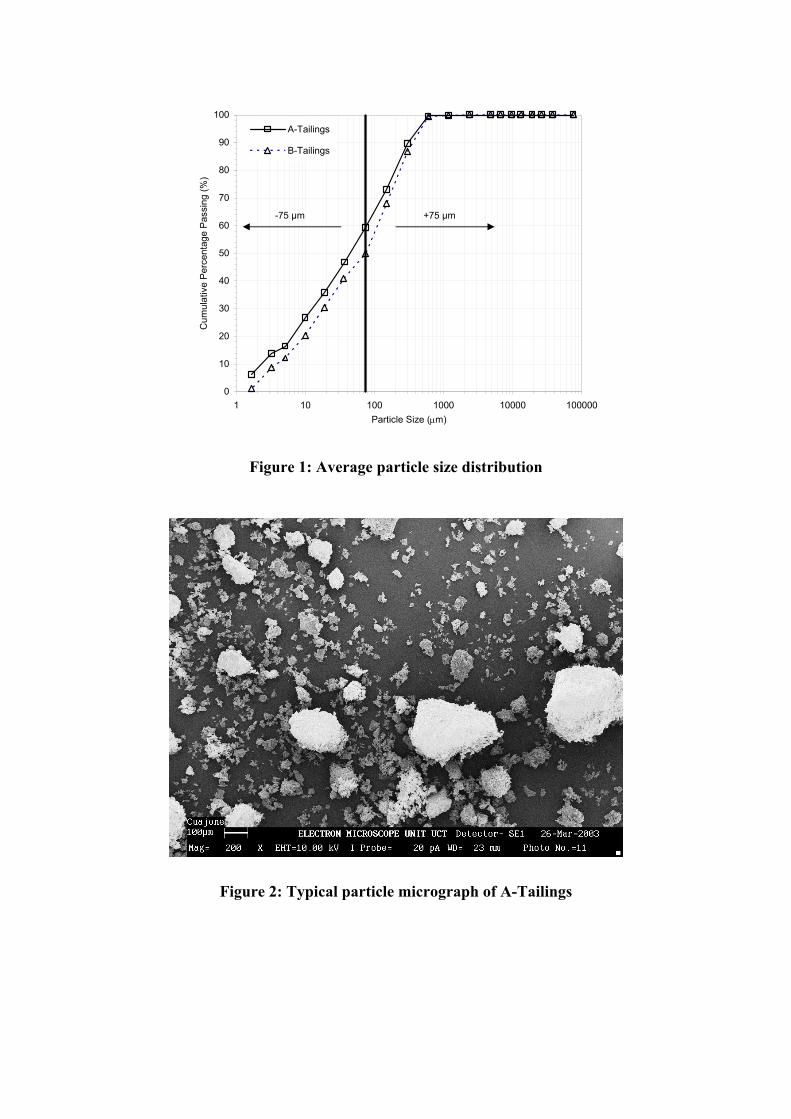
2.1.1 Slurry properties The slurry properties are summarised in Table 1. The particle size distribution is determined by a combination of dry sieving (+75 µm fraction) and hydrometer analysis (-75 µm fraction) according to the method detailed in ASTM D 422-63 “Standard Test Method for Particle Size Analysis of Soils”. Figure 1 shows the particle size distribution of each material. The -75 µm fraction varies from 60% for the A-Tailings to 50% for the B-Tailings.
Electron micrographs show the materials have similar particle shapes. Figure 2 shows a range of fine and coarse particles occurring in A-Tailings material.
Table 1: Measured slurry properties
Parameter A-Tailings B-Tailings d90 particle size (µm) 300 350 d50 particle size (µm) 50 75 d10 particle size (µm) 2.5 4 Solids density, ρs (t/m3) 2.719 2.727 Slurry pH (average of all tests) 8.3 8.2
0
10
20
30
40
50
60
70
80
90
100
1 10 100 1000 10000 100000Particle Size (µm)
Cum
ulat
ive
Per
cent
age
Pas
sing
(%)
A-Tailings
B-Tailings
+75 µm-75 µm
Figure 1: Average particle size distribution
Figure 2: Typical particle micrograph of A-Tailings

2.2 Viscometer Data The rheological properties of the samples were measured in a tube (capillary) viscometer. The tube viscometer comprises a pressure vessel connected to a tube. The sample is loaded into the pressure vessel and discharged through the tube at a controlled flow rate. Pressure loss and flow rate are recorded, allowing the slurry velocity in the tube and wall shear stress to be determined directly. The measured data is presented in a conventional pseudo-shear diagram which is a plot of pseudo-shear rate (Γ) versus wall shear stress (τo), where:
DV8
=Γ (1)
,L4PDand 0
∆=τ (2)
where V = mean mixture velocity (m/s) D = internal tube diameter (m) ∆P = pipeline pressure loss (Pa) L = pipeline length (m). The recorded pseudo shear data are analysed using the generalised Herschel-Bulkley(3) model according to the following equation relating pseudo-shear rate to wall shear stress:
( ) ( ) ( ),
1n1n22
1n3K1n4
DV8 2
yyoy
2yo
n1n
yo
n1
3o
+τ
++τ−τ
τ++τ−τ
τ−τ
τ==Γ
+ (3)
where τy = yield stress (Pa) K = fluid consistency index (Pa.sn) n = flow behaviour index. Equation 3 can be used for a wide variety of time independent fluids, including the power law, yield pseudo-plastic and Bingham fluids. Where a Bingham fluid is used (n = 1), the fluid consistency term is referred to as the plastic viscosity (ηp) and the yield stress is often called the Bingham yield stress (τyB). 2.2.1 Rheological Analysis The rheological parameters for each material are determined using Equation 3. A typical data set for the material is shown in Figure 3. A Bingham approximation is used for the data as it provides a reasonable correlation over the expected range of operating shear rates.
The rheological parameters for each data set are determined and are summarised in Figures 4 and 5 as a function of solids mass concentration. The best fit approximation to the data is shown. The typical exponential increase in viscosity with solids concentration is clear. The Bingham yield stress in Figure 4 for the B-Tailings data increases from 10 Pa to 37 Pa as solids concentration increases from 60%m to 65%m. At 70%m the yield stress is estimated to

be as high as 130 Pa, although this is extrapolating well beyond the measured data set. The A-Tailings have a considerably higher yield stress than the B-Tailings, although it appears that the relationship between plastic viscosity and solids mass concentration is similar for both materials.
0
50
100
150
200
250
300
350
400
450
500
0 50 100 150 200
Pseudo-Shear Rate (s-1)
Wal
l She
ar S
tress
(Pa)
76.8%m
73.2%m
70.0%m
66.9%m
61.5%m
56.3%m
Figure 3: Typical measured data set
0
10
20
30
40
50
60
70
80
90
100
50% 55% 60% 65% 70%Solids mass percentage (%)
Bin
gham
yie
ld s
tress
(Pa)
'
A-Tailings
B-Tailings 1
B-Tailings 2
B-Tailings 3
B-Tailings 4
Figure 4: Yield stress versus solids concentration

0.00
0.05
0.10
0.15
0.20
0.25
50% 55% 60% 65% 70%
Solids mass percentage (%)
Pla
stic
vis
cosi
ty (P
a.s)
A-TailingsB-Tailings 1B-Tailings 2B-Tailings 3B-Tailings 4
Figure 5: Plastic viscosity versus solids concentration
3 SLURRY SYSTEMS
3.1 Design constraints The design rheology conditions for the slurry transport system are governed by:
(i) The requirements at the deposition site,
(ii) The process requirements to produce a suitable high density thickened tailings.
3.1.1 Disposal site constraints The proposed thickened tailings disposal strategy relies on consistent behaviour of the thickened tailings when it is deposited. As the material is deposited it will flow from the deposition points under gravity and will form a long, gradually sloping beach. At low concentrations as the material flows down the slope, gravitational sorting by particle size occurs, the coarser particles settle out nearer to the deposition point and the finer particles are transported further. This results in natural size gradation along the beach with a slightly concave profile. As the solids concentration increases there is less settling of the solid particles and the slopes become planar, even convex, and steeper. The final beach slope at which the tailings deposit is a function of solids concentration and rheology.
The studies showed that the storage capacity of the proposed deposition site at the Pampa Purgatoria relied upon achieving a minimum beach slope of 6%. As the site has a natural fall of 5% it was critical to ensure that the beach slope of the deposited material was greater than the natural fall if there was to be sufficient storage without having to construct excessive earth embankments.
Extensive geotechnical testing and pilot plant test work was done to determine the placement properties of the thickened tailings and it was found that a minimum solids concentration of

67%m was required for the mixed tailings. At lower solids concentrations the beach angle is too low as the slurry viscosity, and in particular the yield stress, is insufficient.
3.1.2 Process constraints The minimum solids concentration of 67%m needed to achieve the necessary 6% slope on the deposition site can be produced using paste thickeners. However, thickener evaluation studies showed that it would be problematic and un-economical to achieve solids concentrations very much greater than 67%m, even though this would be beneficial for the deposition site. The reasons for this are briefly:
(i) Thickeners at the existing mines cannot be upgraded to achieve a combined tailings solids concentration of 67%m due to site and process constraints.
(ii) It would be necessary to thicken the entire process stream. This can only be done downstream of the confluence point of the two mines tailings streams and there would not be significant water recovery at the mine sites at higher elevations.
(iii) The high flocculent cost to thicken the total tailings stream.
3.1.3 Design rheology Based on deposition and process constraints, the design of the slurry transport system is based on the slurry rheology at 67%m, presented in Table 2.
Table 2: Rheology parameters at 67%m solids concentration
Tailings A B Yield stress 101.0 Pa 62.0 Pa Plastic viscosity 0.1077 Pa.s 0.1190 Pa.s
3.2 Canal system The capacity of the existing canals was analysed for the different slurries using the method of Abulnaga(4). On site measurements confirmed that the model provided a good approximation to the flow behaviour of the tailings in the canals.
Analysis of one of the existing canals transporting 6 070 dry tonnes/hour of mixed tailings is summarised in Figure 6 and Figure 7. At a constant slope of 1% it is seen that at low concentrations the canal is deep because of the high volume. As the concentration increases, the flow rate and mean velocity decreases and the canal becomes shallower. The flow remains turbulent. At the transition from turbulent to laminar flow at approximately 65%m solids there is a steep increase in depth and the velocities will decrease to the point where solids will settle out in the canal. To transport the high rheology material requires a steeper slope than the available 1% grade. The analysis shows that the maximum concentration that the canal can safely transport is 65%m. A 1% canal slope is typical and slopes generally are not steeper than 1.5% as the turbulent flow velocities become high and side wall erosion increases significantly.
The requirement to deposit material on the Pampa Purgatoria at 67%m therefore eliminates using the existing canals if the material is thickened upstream of the canals and pipeline transport is required.

0.0%
0.5%
1.0%
1.5%
2.0%
2.5%
3.0%
3.5%
4.0%
4.5%
5.0%
0% 5% 10% 15% 20% 25% 30% 35% 40% 45% 50% 55% 60% 65% 70% 75%
Solids mass concentration (%)
Laun
der g
rade
(%)
Depth: 480 mm
Depth: 705 mm
Depth: 1155 mm
Depth
Width1.530 m
Figure 6: Capacity of canal (6 070 tonnes/hour)
0.00
0.10
0.20
0.30
0.40
0.50
0.60
0.70
0.80
0.90
1.00
1.10
1.20
1.30
1.40
1.50
0% 5% 10% 15% 20% 25% 30% 35% 40% 45% 50% 55% 60% 65% 70% 75%
Solids mass concentration (%)
Can
al d
epth
(m)
0
1
2
3
4
5
6
Mea
n ve
loci
ty (m
/s) .1% grade
2% grade
2% grade
1% grade
Canal depth
Mean velocity
Figure 7: Canal depth and mean velocity versus solids mass concentration (6 070 tonnes/hour)

3.3 Pipeline Options The following factors need to be considered when assessing the feasibility of pipeline transport of high density tailings under gravity:
(i) The pipeline must always be fully pressurised to eliminate slack flow.
(ii) The rheology is sensitive to changes in slurry properties (pH, mineralogy, etc.).
(iii) Pressure gradients in large diameter pipes are low and the flow could be problematic due to laminar flow settling issues.
Best practice design of slurry systems takes into account methods of ensuring fully pressurised flow under varying flow conditions and changes in rheology, however issues relating to laminar flow settling are not always fully accounted for and can be extremely problematic and pose a significant risk(5).
3.3.1 Laminar flow transport When a solid particle settles in laminar flow there is no way to re-suspend the particle. The particles will accumulate on the pipeline invert and effectively reduce the pipeline diameter. It is generally accepted that a pipeline pressure gradient of 1 to 2 kPa/m is needed to force the bed to move along the pipeline if the flow is laminar(5).
High density "paste" tailings in small diameter pipelines have high pressure gradients and can be operated in laminar flow without the risk of blockage. At Southern Peru Copper Corporation the high volumes require large diameter pipelines and the 2 kPa/m pressure gradient cannot be achieved unless pipe diameters are reduced to 370 mm, as shown in Figure 8, where a two pipeline system is considered (each transporting 50% of the flow). This would result in very high velocities of 7 m/s and is clearly not a practical solution.
0.0
0.5
1.0
1.5
2.0
2.5
3.0
0.350 0.400 0.450 0.500 0.550 0.600 0.650 0.700
Internal diameter (m)
Pres
sure
gra
dien
t (kP
a/m
)
Pressure loss at 67%m Pressure loss at 65%m
2 kPa/m limit to slide a settled bed in laminar flow
3035 dry tonnes/pipeline2581 m3/h at 67%m2720 m3/h at 65%m
Figure 8: Pressure gradient versus internal diameter

3.3.2 Design philosophy The thickened tailings tested have a reasonably high yield stress and plastic viscosity. This means that the pipeline system will operate in laminar flow at the required 67%m solids concentration. The pump and pipeline selection must allow for this. As it is not practically possible to achieve the 2 kPa/m pressure gradient necessary to move a settled bed of solids, it is necessary to ensure that the pumps can generate sufficient pressure for turbulent flow to occur above a settled bed. Alternatively flushing water can be added intermittently to increase the flow rate and dilute the slurry until the bed erodes, however this would not be feasible, as it would increase the risk of eroding the deposited tailings.
In this situation a positive displacement pump is better suited to the application than a centrifugal pump as the pump head-discharge curve means that an increase in pressure will not significantly change the flow rate at a constant pump speed. Centrifugal pumps can be used provided there is sufficient capacity in the number of pumps installed and variable speed drives are used. The pipeline flow will need to be monitored and used to control the pump speed.
At a constant flow rate and density, the changing flow in the pipeline is shown in Figure 9 and is as follows:
(i) During normal operation (point A) in laminar flow there will be a gradual accumulation of solids on the pipeline invert.
(ii) The flow area above the bed will reduce as solids continue to deposit on the pipeline invert.
(iii) As the flow area reduces the pump station discharge pressure will rise (point B) as the effective diameter reduces.
(iv) If the pumps have sufficient installed capacity, the flow area will keep reducing until the flow becomes turbulent above the bed (point C).
(v) If the rheology changes and the flow becomes turbulent, the bed will erode and the pressure gradients will decrease until the flow becomes laminar again and solids begin to accumulate.
(vi) During pipeline flushing the solids concentration will decrease and the flow will change from laminar to turbulent as the viscosity decreases.
(vii) If the slurry velocity is greater than the deposition velocity the settled bed will be eroded and flushed from the pipeline.

0.0
0.1
0.2
0.3
0.4
0.5
0.6
0.7
0.8
0.9
1.0
0 1000 2000 3000 4000 5000
Slurry flow rate (m³/h)
Pre
ssur
e gr
adie
nt (k
Pa/
m)
Pressure loss curves all at same %m solids in same diameter pipelineEffective flow area varies as bed height variesPoints A, B and C at constant tonnage and flow rate.
A
B
C
Figure 9: Change in pressure gradient as flow area reduces at a constant flow rate
3.3.3 Pipeline analysis Using the above design approach a typical analysis conducted is shown in Figure 10. The pressure gradient versus velocity relationship at 63%m, 65%m and 67%m is calculated for a 583 mm diameter pipeline. At a constant design tonnage the flow rate changes as the solids concentration changes.
0.0
0.1
0.2
0.3
0.4
0.5
0.6
0.7
0.8
0.9
1.0
0 1000 2000 3000 4000 5000 6000
Slurry flow rate (m³/h)
Pre
ssur
e gr
adie
nt (k
Pa/
m)
63%m
67%m
65%m
A
B
B'
C
C'
3 035 dry tonnes/pipeline2 581 m3/h at 67%m2 720 m3/h at 65%m2 868 m3/h at 63%m
Figure 10: Change in pressure gradient as solids concentration varies

At 63%m the operating point A is in turbulent flow and there should be no settling of solids on the pipeline invert. The required pressure gradient is 0.217 kPa/m.
As the solids concentration increases to 65%m the flow becomes laminar as the viscous stresses increase. At point B the pressure gradient is 0.321 kPa/m. As solids accumulate on the pipe invert under laminar flow conditions, the pressure gradient will rise to 0.393 kPa/m (B') when the flow becomes turbulent.
At 67%m the change in pressure gradient from laminar flow to achieve turbulent flow is more dramatic. The pressure gradient will change from 0.530 kPa/m to 0.811 kPa/m, an increase of 53%, as the effective flow area reduces from C to C′.
The effect of increasing solids concentration on pressure gradient is clear:
• At 63%m the system will operate in turbulent flow and pressure gradients are low. The design of the control system and choke stations is reasonably straightforward as the potential variation in pressure gradients is small.
• At 65%m the system must be designed to accommodate laminar flow settling and there is likely to be a moderate increase in pressure gradient as flow conditions change from laminar to turbulent flow. Centrifugal pumps could be used if the gravity head is insufficient, and provided sufficient head can be generated by the centrifugal pump station.
• At 67%m there is a large variation in pressure gradient as flow conditions change from laminar to turbulent flow and this increases the complexity of the design considerably. To ensure fully pressurised flow the choke station must dissipate a wide range of pressures. If there is insufficient gravity head available, then the pumping pressure requirements are considerable and positive displacement pumps would be required.
4 CONCLUSIONS
The implementation of high density thickened tailings on a large scale at Southern Peru Copper Corporation poses unique challenges. Test work demonstrated that the feasibility of the system is driven largely by the specific site requirements of the disposal facility. In order to achieve the required storage volumes at the disposal facility, it is necessary to prepare and transport slurry with a reasonably high yield stress. Although the analysis of the Southern Peru Copper Corporation system is unique to the material specific rheology, the study highlighted the following important issues: (i) High density slurry flow transport in canals is, like pipeline transport, very susceptible
to slurry rheology and becomes unstable as the viscosity increases. Small variations in water chemistry, pH, host ore mineralogy and the milling process will affect the rheology.

(ii) Canal transport of high density thickened tailings in laminar flow requires steeper gradients than are typically available in existing canal systems in South American mines.
(iii) The pipeline transport of high volumes of thickened tailings in large diameter
pipelines normally results in laminar flow conditions. (iv) Laminar flow settling in large diameter pipelines needs to be controlled by ensuring
the system has the capacity to either flush settled solids from the pipeline, or allowing the flow regime to revert to turbulent flow when the settled bed height reduces the effective pipe diameter significantly.
ACKNOWLEDGEMENTS The authors would like to thank the management of Southern Peru Copper Corporation for permission to publish this paper. The data analysis and test work completed by Eric Paulsen, Fritz van Sittert and Ruben Vargas is gratefully acknowledged. REFERENCES (1) Robinsky, E. I. (1999). "Thickened tailings disposal in the mining industry", E.I.
Robisnky Associates Ltd. Canada. (2) Williamson, J.R.G., Paterson, A.J.C., Oliveros Salas, U. (2004). "Paste tailings
disposal on a major scale at Southern Peru Copper Corporation: A Case Study", Paste 2004, Cape Town, South Africa, 29 March – 1 April 2004.
(3) Govier, G.W., Aziz K. (1972). "The flow of complex mixtures in pipes", Von Nostrand Reinhold Company.
(4) Abulnaga, B. (2002). "Slurry Systems Handbook", McGraw-Hill, New York. (5) Cooke, R. (2002). "Laminar flow settling: The potential for unexpected problems",
Proc. 15th International Conference on Hydrotransport, Banff.


