Embed Size (px)
Citation preview

TAKING CREDIT FOR LOSS CONTROLMEASURES IN THE PLANT WITH THE LIKELYLOSS FIRE AND EXPLOSION INDEX (LL-F&EI)
N. Jensen� and S. B. Jørgensen
CAPEC, Department of Chemical Engineering, Technical University of Denmark, Kgs. Lyngby,
Denmark.
Abstract: This communication proposes a new relationship for estimation of the damage factor(DF) used in the Dow Fire and Explosion Index (F&EI). The proposed new relation more clearlyshows how the damage factor depends on other factors in the F&EI, such as material factor (MF)and Process Unit Hazards Factor, and leads to the definition of a new index which accounts forloss control measures implemented in the plant, and thus gives a measure of risk. Analysisshows that three types of relations exist between DF and Process Unit Hazards Factor depend-ing on the size of the MF—low, medium or high. Further analysis shows, that the procedure in thecurrent F&EI Guide may overestimate the DF for a very low MF and moderate to high ProcessUnit Hazards Factor.The analysis leads to the definition of the Likely Loss Fire & Explosion Index, which provides
an estimate of risk of losses from fires and explosions as well as degrees of risk similar to theestimate of hazards and degrees of hazard associated with the Fire & Explosion Index.
Keywords: risk assessment; Fire & Explosion Index.
INTRODUCTION
The Dow Fire and Explosion Index was devel-oped by the Dow Chemical Company in the1960s as a tool for plant engineers to give rela-tive value to the risk of individual process unitlosses due to fires and explosions and to com-municate these risk to management in termseasily understood, i.e., potential of financiallosses due to lost production and damage toplant facilities. The index is still widely used,and has been upgraded seven times. Thisindex estimates the hazards of a single pro-cess unit based on chemical properties andinventories, and then uses plant constructioncost or replacement cost to estimate the poten-tial risk in dollar terms. The aim of this com-munication is to develop an index, which is ameasure of risk and takes into account riskreduction measures implemented or proposedfor the plant unit, such as process controlsystems, material isolation systems and fireprotection systems. Thus as the F&EI ratesthe hazards, the proposed index rates the risk.
DOW’S FIRE AND EXPLOSION INDEXPROCEDURE
Based on their in house experiences withfires and explosions during the late fifties and
early sixties the Dow Chemical Companydeveloped the Fire and Explosion Index(F&EI) as a tool to rate the hazards from firesor explosions at their world wide facilities ona uniform scale. Over the years the index hasbeen adjusted based on both internal andexternal data as well as qualitative and quanti-tative analysis. The aim of this tool is to com-municate the risk to management in such away, that management may take appropriateactions to reduce the risk. The purpose is notto rate a given facility as safe or unsafe, butto give a relative ranking of hazards and riskswithin an organization. The current version ofthe guide is available from AIChE (1994), andis referred to as the F&EI Guide in the remain-der of this communication.The general procedure for using the F&EIGuide is shown in Figure 1, and involves thefollowing steps:
(1) Amaterial factor (MF)which is ameasure ofthe reactivity and flammability hazardsassociated with a material as defined bythe NFPA reactivity and flammability rat-ings, NR and NF. The flammability rating isfurther related to the materials flash pointtemperature and boiling point temperature.
(2) A general process hazards factor (F1)which is a measure of reaction character-istics, i.e., exothermal or endothermal,
51 Vol 85 (B1) 51–58
�Correspondence to:Mr N. Jensen, CAPEC,Department of ChemicalEngineering, TechnicalUniversity of Denmark,Søltofts Plads 229 Kgs.Lyngby, DK-2800, Denmark.E-mail: [email protected]
DOI: 10.1205/psep06001
0957–5820/07/$30.00þ 0.00
Process Safety andEnvironmental Protection
Trans IChemE,Part B, January 2007
# 2007 Institutionof Chemical Engineers

Figure 1. Procedure for calculating the Dow F&EI and other risk analysis information. The dashed line encloses the procedure for rating thehazards of a process unit, while the dash–dot line encloses the procedure for estimaing the management risk information. This paper proposesa risk index as an alternative to the management risk information estimations.
Trans IChemE, Part B, Process Safety and Environmental Protection, 2007, 85(B1): 51–58
52 JENSEN and JØRGENSEN
and of facility characteristics, i.e., access, drainage, out-door or indoor units, and handling or transfer of chemicals.
(3) A special process hazards factor (F2) which is a measureof material characteristics, i.e., toxicity, corrosion, dust,and of operation characteristics, i.e., extreme pressuresand/or temperatures, temperatures in flammable range,amount of material and special equipment with high fireand explosion potential.
These steps—the hazard rating steps—are shown enclosedby a dashed line in Figure 1.The F&EI is simply the product of these three factors, i.e.,
F&EI ¼ MF � F1 � F2 ¼ MF � F3 (1)
Based on the value of the index, the hazard of a process unitis rated as light, moderate, intermediate, heavy or severe(AIChE, 1994).
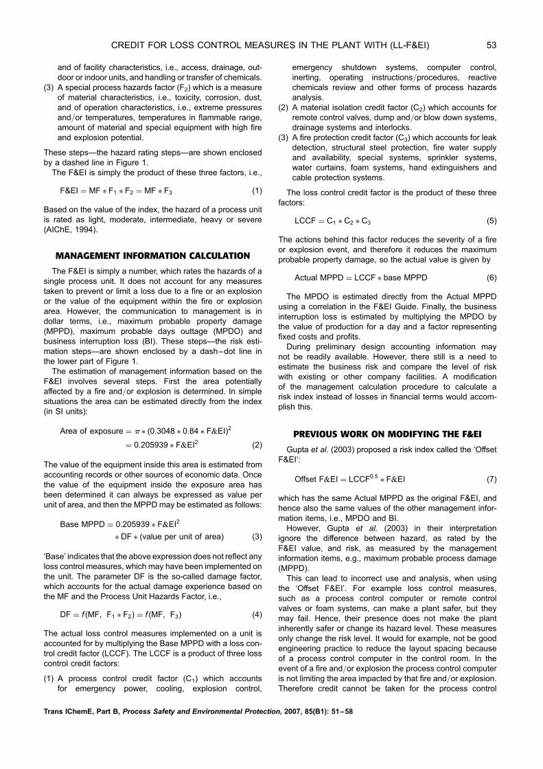
MANAGEMENT INFORMATION CALCULATION
The F&EI is simply a number, which rates the hazards of asingle process unit. It does not account for any measurestaken to prevent or limit a loss due to a fire or an explosionor the value of the equipment within the fire or explosionarea. However, the communication to management is indollar terms, i.e., maximum probable property damage(MPPD), maximum probable days outtage (MPDO) andbusiness interruption loss (BI). These steps—the risk esti-mation steps—are shown enclosed by a dash–dot line inthe lower part of Figure 1.The estimation of management information based on the
F&EI involves several steps. First the area potentiallyaffected by a fire and/or explosion is determined. In simplesituations the area can be estimated directly from the index(in SI units):
Area of exposure ¼ p � (0:3048 � 0:84 � F&EI)2
¼ 0:205939 � F&EI2 (2)
The value of the equipment inside this area is estimated fromaccounting records or other sources of economic data. Oncethe value of the equipment inside the exposure area hasbeen determined it can always be expressed as value perunit of area, and then the MPPD may be estimated as follows:
Base MPPD ¼ 0:205939 � F&EI2
� DF � (value per unit of area) (3)
‘Base’ indicates that the above expression does not reflect anyloss control measures, which may have been implemented onthe unit. The parameter DF is the so-called damage factor,which accounts for the actual damage experience based onthe MF and the Process Unit Hazards Factor, i.e.,
DF ¼ f (MF, F1 � F2) ¼ f (MF, F3) (4)
The actual loss control measures implemented on a unit isaccounted for by multiplying the Base MPPD with a loss con-trol credit factor (LCCF). The LCCF is a product of three losscontrol credit factors:
(1) A process control credit factor (C1) which accountsfor emergency power, cooling, explosion control,
emergency shutdown systems, computer control,inerting, operating instructions/procedures, reactivechemicals review and other forms of process hazardsanalysis.
(2) A material isolation credit factor (C2) which accounts forremote control valves, dump and/or blow down systems,drainage systems and interlocks.
(3) A fire protection credit factor (C3) which accounts for leakdetection, structural steel protection, fire water supplyand availability, special systems, sprinkler systems,water curtains, foam systems, hand extinguishers andcable protection systems.
The loss control credit factor is the product of these threefactors:
LCCF ¼ C1 � C2 � C3 (5)
The actions behind this factor reduces the severity of a fireor explosion event, and therefore it reduces the maximumprobable property damage, so the actual value is given by
Actual MPPD ¼ LCCF � base MPPD (6)
The MPDO is estimated directly from the Actual MPPDusing a correlation in the F&EI Guide. Finally, the businessinterruption loss is estimated by multiplying the MPDO bythe value of production for a day and a factor representingfixed costs and profits.During preliminary design accounting information may
not be readily available. However, there still is a need toestimate the business risk and compare the level of riskwith existing or other company facilities. A modificationof the management calculation procedure to calculate arisk index instead of losses in financial terms would accom-plish this.
PREVIOUS WORK ON MODIFYING THE F&EI
Gupta et al. (2003) proposed a risk index called the ‘OffsetF&EI’:
Offset F&EI ¼ LCCF0:5� F&EI (7)
which has the same Actual MPPD as the original F&EI, andhence also the same values of the other management infor-mation items, i.e., MPDO and BI.However, Gupta et al. (2003) in their interpretation
ignore the difference between hazard, as rated by theF&EI value, and risk, as measured by the managementinformation items, e.g., maximum probable process damage(MPPD).This can lead to incorrect use and analysis, when using
the ‘Offset F&EI’. For example loss control measures,such as a process control computer or remote controlvalves or foam systems, can make a plant safer, but theymay fail. Hence, their presence does not make the plantinherently safer or change its hazard level. These measuresonly change the risk level. It would for example, not be goodengineering practice to reduce the layout spacing becauseof a process control computer in the control room. In theevent of a fire and/or explosion the process control computeris not limiting the area impacted by that fire and/or explosion.Therefore credit cannot be taken for the process control
Trans IChemE, Part B, Process Safety and Environmental Protection, 2007, 85(B1): 51–58
CREDIT FOR LOSS CONTROL MEASURES IN THE PLANT WITH (LL-F&EI) 53

computer or any other loss control measures when usingthe F&EI to calculate equipment spacing in plant layout,as in the equation for radius of exposure, F&EI Guide(AIChE, 1994):
R ¼ 0:256 � F&EI (8)
A plant layout, which minimizes the loss from fires andexplosions will attempt to space equipment, so the exposureareas defined by the above radius does not overlap, andhence a fire or explosion in one process unit does not havea domino effect on a nearby unit. The interpretation of theradius of exposure or area of exposure calculated fromthe Offset F&EI using the same multiplication factor asin the F&EI Guide, i.e., 0.256 (in SI units), is unclear, as isthe replacement value calculated from this area. Unfortu-nately Gupta et al. (2003) concludes, based on ‘OffsetF&EI’, that ‘the equipment can be spread out less to savefrom domino effect’, and that ‘it implies lesser land require-ments’ or ‘shorter pipe lengths’.Gupta et al. (2003) also state ‘the loss control measures
are installed to reduce the hazard potential of a process’.Loss control measures are taken to reduce the risk, as indi-cated by MPPD, MPDO or BI. The hazard may only bereduced by applying the principles of inherently saferdesign. Neither is it correct to state, that the ‘Offset F&EI’makes the system inherently safer. Only system changes,i.e., process design and process route changes will makethe system inherently safer.The proposed ‘Offset F&EI’ does however have the follow-
ing benefit:
. Easier evaluation of cost versus benefit of different losscontrol measures especially during design and applicationfor a permit from authorities.
However, the other advantages claimed by Gupta et al.(2003), such (a) reduction of the area of exposure and thehazard status of the process unit, (b) reduced insurance pre-miums due to use of a different index, (c) a more compactplant layout, (d) reduced cost of piping, (e) more manageableemergency plans, or (f) reduced on-site and off-site conse-quences, appear not to hold.
ANALYSIS OF DAMAGE FACTOR/MATERIALFACTOR RELATIONS
The Process Unit Hazards Factor, F3, is limited to values inthe interval from 1 to 8 according to the F&EI Guide. InFigure 2 the Damage Factor is shown as a function of theMF, which can only assume the discrete values 1, 4, 10,14, 16, 21, 24, 29 and 40. The Process Unit HazardsFactor is an almost continuously variable parameter, whichcan assume most values in the interval from 1.0 to 8.0. Aninstructive visualization is therefore to show the DF as a func-tion of the Process Unit Hazards Factor, F3, with the MF as aparameter, as is done in Figure 3.Figure 3 reveals three clearly different shapes of the
relationship between DF and Process Unit Hazards Factor.One almost linear relationship for small MF, i.e., 1, 4 or 10;an S-shaped relationship for intermediate MF, i.e., 14 or 16,and a damped exponential relationship for high MF, i.e., 21,24, 29 or 40.
The parallel lines in Figure 3 indicate, that the DF is closelyproportional to the material factor. This is confirmed byFigure 4, which shows a plot of the DF/MF versus F3. ForMF.1 all lines of DF/MF versus Process Unit HazardsFactor collapse to a single broad line. This analysis also indi-cates, that for MF ¼ 1 and Process Unit Hazards Factor.2the DF estimation according to the current F&EI Guidedeviates from the general trend. This could mean, that theprocedure in the current F&EI Guide overestimates the DFfor a very low MF and a moderate to high Process UnitHazards Factor.Figure 5 shows an enlargement of a section of Figure 4.
This enlargement also indicates three types of relationshipbetween the ratio of Damage Factor to Material Factor(DF/MF), and Process Unit Hazards Factor. The relationshipfor MF ¼ 1, 4 or 10 appears almost linear. For MF ¼ 14 or 16the relationship appears S-shaped, and for higher MF adamped exponential relationship is evident. This is confirmedby linear regression of the data, which give R 2 values above0.997 for the lower MF values (1, 4 or 10), and less than 0.98for the higher MF values (40, 29 or 24), when fitted to a linearfunction of F3.Regression analysis of DF versus Process Unit Hazards
Factor for MF.1 gives the following equation:
DF ¼ MF � (0:0143þ 0:00284 � F3) (9)
Figure 2. DF, as a function of the MF, with the Process Unit HazardsFactor, F3, as parameter, as found in the F&EI Guide.
Figure 3. DF as function of the Process Unit Hazards Factor with theMF as parameter. The parallel lines indicate, that the DF appears tobe proportional with the MF to a certain extend.
Trans IChemE, Part B, Process Safety and Environmental Protection, 2007, 85(B1): 51–58
54 JENSEN and JØRGENSEN

with R2 statistics of 0.64. This rather low R2 value indi-cates, that this equation does not capture all the information inthe original relationship shown in Figure 3. A commonapproach in risk assessment is to apply a conservativeapproach. In the case of DF, this means selecting largestDF/MF ratio for a given Process Unit Hazards Factor.This conservative approach corresponds to the followingrelationship
DF/MF ¼ 0:0174þ 0:00339 � F3 (10)
However, this approach may overestimate the DF/MF ratioby between 64% and 96% depending on the Process UnitHazards Factor. This overestimation will be carried on tothe MPPD, MPDO and BI information, which is not accep-table in evaluation of existing plants. However, duringprocess design, where the goal is to compare the risk ofalternative designs, the situation may be different, and itmay have merit to use the conservative relationship givenin equation (10).The overestimation may be avoided by using the actual
polynomial relations between DF/MF and F3 given in Appen-dix A or the relations between DF and F3 given in Appendix Bfor the different values of MF.
This analysis shows, that several possibilities exist formodifying the current relationships between DF, MF andProcess Unit Hazards Factor in the current version of theF&EI Guide to obtain a more smooth graphical represen-tation. The analysis further suggest, that a limiting DF/MFratio can be defined for a given Process Unit Hazards Factor.
A Conservative MPPD Estimate
Based on the above analysis and equation (3) a conserva-tive estimate—upper bound—on the Base MPPD may beexpressed by
Base MPPD ¼ 0:205939 � F&EI2 �MF
� (0:0174þ 0:00339 � F3)
� (value/unit area) (11)
or
Base MPPD ¼ 0:205939 � F&EI2
� (0:0174 �MFþ 0:00339 � F&EI)
� (value/unit area) (12)
Finally, if account is taken of loss control measures alreadyimplemented in the plant or unit through a loss controlcredit factor (LCCF), then an upper bound on the ActualMPPD could be
Actual MPPD ¼ LCCF � 0:205939F&EI2
� (0:0174 �MFþ 0:00339 � F&EI)
� (value/unit area)
LIKELY LOSS FIRE AND EXPLOSION INDEX
While in many cases economic data such as constructioncost and equipment value per unit of area may be available,this is not the case during initial phases of process design.During initial process design an index is desired, whichaccounts for the hazards due to the chemicals used andthe inventories needed, as well as the risk reductioninherent in loss control measures, such as e.g., a computerprocess control system. This section proposes such anindex.The maximum probable property damage is seen from the
foregoing analysis to be of the following form
Actual MPPD ¼ g(LCCF, MF, F3, value/unit of area)
(13)
since the F&EI is function of MF and F3. From this functionalrelationship it is evident, that one can define an index,which takes into account the loss control measuresimplemented in the plant or unit under investigation. Onepossibility for such a likely loss fire and explosion index orLL-F&EI is the following
LL-F&EI ¼ 0:205939 � LCCF � DF � (F&EI)2 (14)
where the coefficient derives from the exposure area calcu-lation in the F&EI Guide (AIChE, 1994). However, since the
Figure 4. DF/MF, versus the Process Unit Hazards Factor. ForMF . 1, all DF appears to fall on the same broad line.
Figure 5. Enlargement of section of Figure 4 showing three types ofrelationship between DF/MF and Process Unit Hazards Factor. Therelationship for MF ¼ 1, 4 or 10 appears almost linear. For MF ¼ 14or 16 the relationship appears S-shaped, and for higher MF adamped exponential relationship is evident.
Trans IChemE, Part B, Process Safety and Environmental Protection, 2007, 85(B1): 51–58
CREDIT FOR LOSS CONTROL MEASURES IN THE PLANT WITH (LL-F&EI) 55

likely losses after implementation of loss control measures,will be lower than without these measures, it is desired tocreate a LL-F&EI with the property, that its value is lessthan or equal to the F&EI. Therefore the following definitionis more suitable:
LL-F&EI ¼ 0:453805 � SQRT(LCCF � DF) � F&EI
(15)
The index defined here is based on the same information asthe F&EI, i.e., the material in the plant, MF, and the planthazards level, F3, as well as the loss control measures.This information is generally available during processdesign, and hence the LL-F&EI may be applied duringdesign to arrive at a design which limits risk to an acceptablelevel. Furthermore, if the damage factor is calculated usingthe equations in appendix A, then the MPPD, MPDO andBI information may be obtained using the relations in theF&EI Guide. The procedure for estimation of the LL-F&EI isshown in Figure 6.Also based on already accumulated information in com-
panies like The Dow Chemical Company risk severity cat-egories may be defined similar to the hazard severitycategories associated with the F&EI. Actually for the worstcase of unit loss control credit factor and unit damagefactor the categories in Table 1 could be used.
For details on the calculation of MPDO and BI fromthe Actual MPPD the reader is referred to the F&EI Guide(1994).
USING THE LL-F&EI
Table 2 shows the use of the proposed risk index on anindustrial size aniline reactor, which was placed indoorswith poor access and drainage, and to the heat integrateddistillation pilot plant (HiDPP) at the Department ofChemical Engineering at the Technical University ofDenmark, which is also placed indoors with poor access.In neither case are meaningful economic data available.Both the reactor and the distillation column involve materialswith a moderate material factor. Both are indoor units withpoor drainage and inadequate ventilation. However, thereactor represents an intermediate to heavy hazard due to
Figure 6. Procedure for estimating of the LL-F&EI. Only the elements within the dash–dot line has changed compared with the procedure shownin the F&EI Guide.
Table 1. Suggested LL-F&EI degrees ofrisk categories.
LL-F&EI range Degree of risk
1–27 Light28–43 Moderate44–57 Intermediate58–71 Heavy72–up Severe
Trans IChemE, Part B, Process Safety and Environmental Protection, 2007, 85(B1): 51–58
56 JENSEN and JØRGENSEN
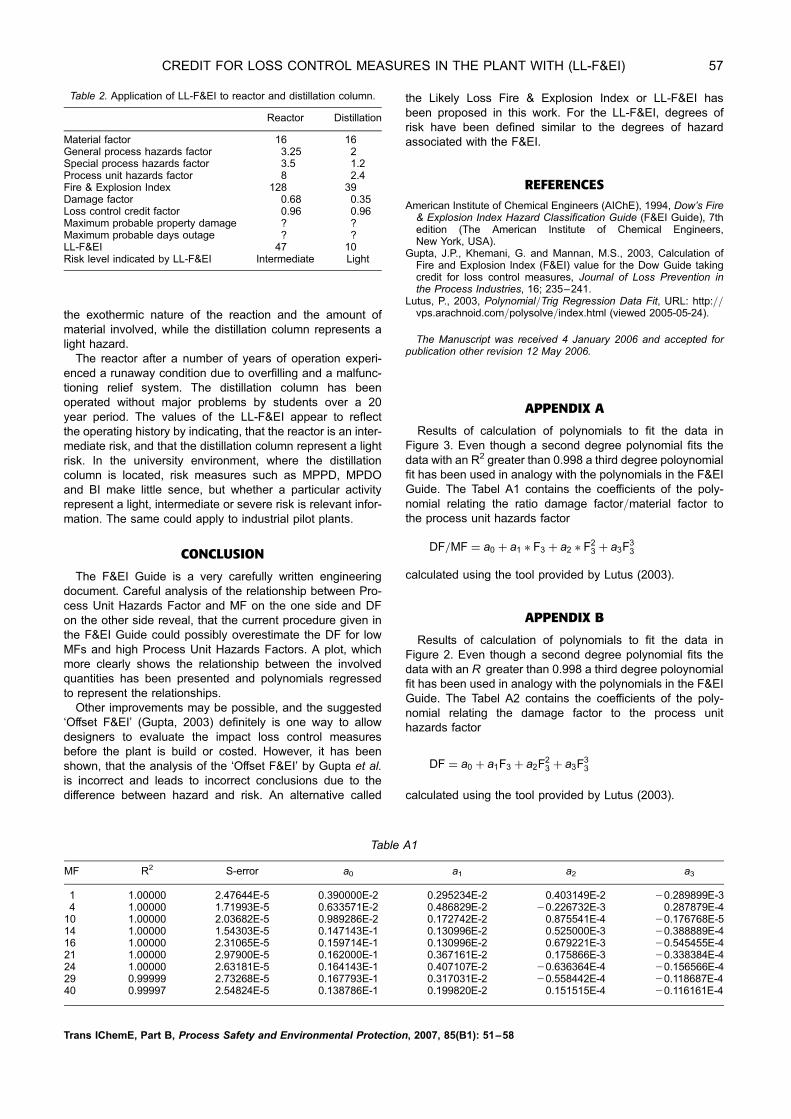
the exothermic nature of the reaction and the amount ofmaterial involved, while the distillation column represents alight hazard.The reactor after a number of years of operation experi-
enced a runaway condition due to overfilling and a malfunc-tioning relief system. The distillation column has beenoperated without major problems by students over a 20year period. The values of the LL-F&EI appear to reflectthe operating history by indicating, that the reactor is an inter-mediate risk, and that the distillation column represent a lightrisk. In the university environment, where the distillationcolumn is located, risk measures such as MPPD, MPDOand BI make little sence, but whether a particular activityrepresent a light, intermediate or severe risk is relevant infor-mation. The same could apply to industrial pilot plants.
CONCLUSION
The F&EI Guide is a very carefully written engineeringdocument. Careful analysis of the relationship between Pro-cess Unit Hazards Factor and MF on the one side and DFon the other side reveal, that the current procedure given inthe F&EI Guide could possibly overestimate the DF for lowMFs and high Process Unit Hazards Factors. A plot, whichmore clearly shows the relationship between the involvedquantities has been presented and polynomials regressedto represent the relationships.Other improvements may be possible, and the suggested
‘Offset F&EI’ (Gupta, 2003) definitely is one way to allowdesigners to evaluate the impact loss control measuresbefore the plant is build or costed. However, it has beenshown, that the analysis of the ‘Offset F&EI’ by Gupta et al.is incorrect and leads to incorrect conclusions due to thedifference between hazard and risk. An alternative called
the Likely Loss Fire & Explosion Index or LL-F&EI hasbeen proposed in this work. For the LL-F&EI, degrees ofrisk have been defined similar to the degrees of hazardassociated with the F&EI.
REFERENCESAmerican Institute of Chemical Engineers (AIChE), 1994, Dow’s Fire
& Explosion Index Hazard Classification Guide (F&EI Guide), 7thedition (The American Institute of Chemical Engineers,New York, USA).
Gupta, J.P., Khemani, G. and Mannan, M.S., 2003, Calculation ofFire and Explosion Index (F&EI) value for the Dow Guide takingcredit for loss control measures, Journal of Loss Prevention inthe Process Industries, 16; 235–241.
Lutus, P., 2003, Polynomial/Trig Regression Data Fit, URL: http://vps.arachnoid.com/polysolve/index.html (viewed 2005-05-24).
The Manuscript was received 4 January 2006 and accepted forpublication other revision 12 May 2006.
APPENDIX A
Results of calculation of polynomials to fit the data inFigure 3. Even though a second degree polynomial fits thedata with an R2 greater than 0.998 a third degree poloynomialfit has been used in analogy with the polynomials in the F&EIGuide. The Tabel A1 contains the coefficients of the poly-nomial relating the ratio damage factor/material factor tothe process unit hazards factor
DF=MF ¼ a0 þ a1 � F3 þ a2 � F23 þ a3F
33
calculated using the tool provided by Lutus (2003).
APPENDIX B
Results of calculation of polynomials to fit the data inFigure 2. Even though a second degree polynomial fits thedata with an R greater than 0.998 a third degree poloynomialfit has been used in analogy with the polynomials in the F&EIGuide. The Tabel A2 contains the coefficients of the poly-nomial relating the damage factor to the process unithazards factor
DF ¼ a0 þ a1F3 þ a2F23 þ a3F
33
calculated using the tool provided by Lutus (2003).
Table A1
MF R2 S-error a0 a1 a2 a3
1 1.00000 2.47644E-5 0.390000E-2 0.295234E-2 0.403149E-2 20.289899E-34 1.00000 1.71993E-5 0.633571E-2 0.486829E-2 20.226732E-3 0.287879E-4
10 1.00000 2.03682E-5 0.989286E-2 0.172742E-2 0.875541E-4 20.176768E-514 1.00000 1.54303E-5 0.147143E-1 0.130996E-2 0.525000E-3 20.388889E-416 1.00000 2.31065E-5 0.159714E-1 0.130996E-2 0.679221E-3 20.545455E-421 1.00000 2.97900E-5 0.162000E-1 0.367161E-2 0.175866E-3 20.338384E-424 1.00000 2.63181E-5 0.164143E-1 0.407107E-2 20.636364E-4 20.156566E-429 0.99999 2.73268E-5 0.167793E-1 0.317031E-2 20.558442E-4 20.118687E-440 0.99997 2.54824E-5 0.138786E-1 0.199820E-2 0.151515E-4 20.116161E-4
Table 2. Application of LL-F&EI to reactor and distillation column.
Reactor Distillation
Material factor 16 16General process hazards factor 3.25 2Special process hazards factor 3.5 1.2Process unit hazards factor 8 2.4Fire & Explosion Index 128 39Damage factor 0.68 0.35Loss control credit factor 0.96 0.96Maximum probable property damage ? ?Maximum probable days outage ? ?LL-F&EI 47 10Risk level indicated by LL-F&EI Intermediate Light
Trans IChemE, Part B, Process Safety and Environmental Protection, 2007, 85(B1): 51–58
CREDIT FOR LOSS CONTROL MEASURES IN THE PLANT WITH (LL-F&EI) 57

Table B1
MF R2 S-error a0 a1 a2 a3
1 0.99999 2.47644E-5 0.390000E-2 0.295234E-2 0.403149E-2 20.289899E-34 0.99999 2.74585E-5 0.258071E-1 0.191012E-1 20.816666E-3 0.1083333E-310 0.99999 2.65908E-5 0.986000E-1 0.175904E-1 0.810606E-3 20.131313E-314 0.99999 3.51250E-5 0.205857 0.189795E-1 0.761742E-2 20.569192E-316 0.99999 2.62494E-5 0.256814 0.198081E-1 0.110723E-1 20.881061E-321 0.99999 2.76548E-5 0.340264 0.765700E-1 0.390260E-2 20.729293E-324 0.99999 2.59731E-5 0.395821 0.964008E-1 20.134167E-2 20.380556E-329 0.99999 1.87064E-5 0.484843 0.942001E-1 20.213561E-3 20.311869E-340 0.99999 9.10893E-6 0.554093 0.808253E-1 0.319481E-3 20.439141E-3
Trans IChemE, Part B, Process Safety and Environmental Protection, 2007, 85(B1): 51–58
58 JENSEN and JØRGENSEN