Embed Size (px)
Citation preview
TSL_TallyBrochure_March_2011_v4.indd 2
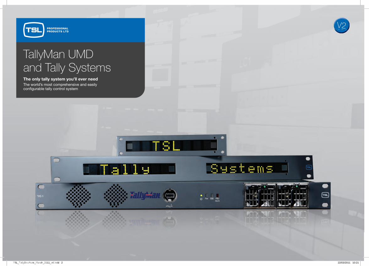
TallyMan UMD and Tally SystemsThe only tally system you’ll ever needThe world’s most comprehensive and easilycon� gurable tally control system
PROFESSIONALPRODUCTS LTD
PROFESSIONALPRODUCTS GROUP
22/03/2011 10:21
V2

TallyMan – Product overview
In addition to the TallyMan range, TSL Professional Products Ltd also specialise in Audio Monitoring, Power Management custom devices – thousands of which are in operation all over the world.
For further information on our product range and expertise, visit www.tsl.co.uk/products or call +44 (0) 1628 676 221
UMD PORTS MAXIMUM RS422 RS232 CONFIGURABLE GPI DEDICATED GPI DEDICATED GPI DEDICATED GPI ETHERNET OVERALL NUMBER OF PLU PORTS PORTS INPUT & OUTPUTS OPTO OUTPUTS RELAY OUTPUTS OPTO INPUTS SIZE POWER SUPPLIES
TM1 8 38 (90W) 2 1 64 1 1RU 1
TM2 16 70 (175W) 5 1 128 1 2RU 1
TM2 Plus 16 70 (175W) 6 1 48 32 1 2RU 1
TMC1 3 (max 32) 1 2 1RU 1
ESP-1R+ 32 64 32 1 1RU 1
CTD-1Si 1 1 64 32 1RU 1
PSU22-1 48 96 (250W) 2RU 1
PSU22-2 48 96 (250W) 2RU 2
ABBREVIATIONS OVERALL SIZE VISIBLE APERTURE CHARACTER POWER ILLUMINATION TALLY INPUT PROTOCOLS (WxHxD) SIZE (WxH) HEIGHT CONSUMPTION COLOUR COLOUR VOLTAGE
UMD-S8C Single 8 character 174 x 38 x 60mm 162 x 19mm 17mm 2.5 watts – Red/Green Red Nominal +24v TSL UMD colour display 1PLU (typically) unregulated
UMD-D8C Single 8 character 174 x 38 x 60mm 162 x 19mm 17mm 2.5 watts – Red/Green/Amber Red/Green/Amber Nominal +24v TSL UMD, colour display 1PLU (typically) unregulated ProBel SWP-04, ProBel SWP-06
UMD-D16 Single 16 character 314 x 36 x 32mm 308 x 19mm 17mm 5.0 watts – Red/Green/Amber Red/Green/Amber Nominal +24v TSL UMD, triple colour display 2PLU (typically) unregulated ProBel SWP-04, ProBel SWP-06
UMD-DD8C Dual 8 character 382 x 36 x 32mm 162 x 19mm 17mm 5.0 watts – Red/Green/Amber Red/Green/Amber Nominal +24v TSL UMD, triple colour display 2PLU (typically) unregulated ProBel SWP-04, ProBel SWP-06
UMD Products
Tallyman Controller and Interface Products
TSL_TallyBrochure_March_2011_v4.indd 3 22/03/2011 10:21
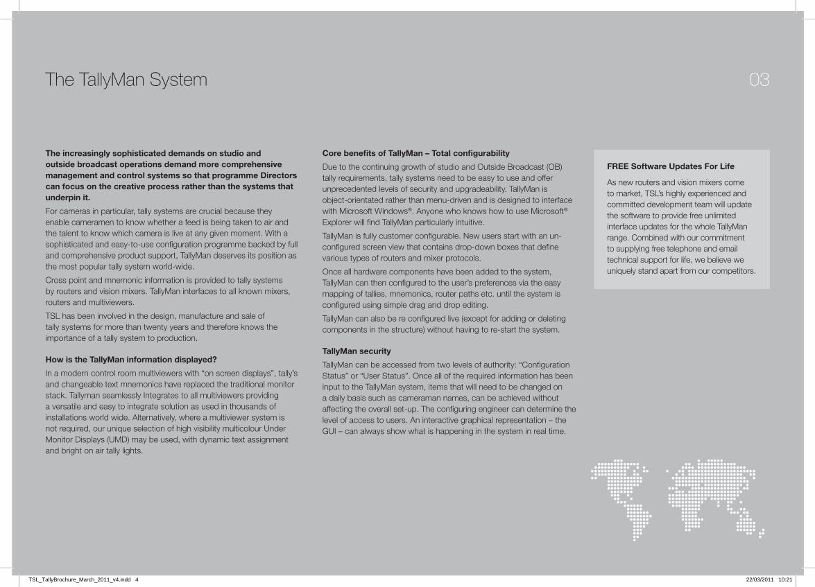
The TallyMan System
The increasingly sophisticated demands on studio and outside broadcast operations demand more comprehensive management and control systems so that programme Directors can focus on the creative process rather than the systems that underpin it.
For cameras in particular, tally systems are crucial because they enable cameramen to know whether a feed is being taken to air and the talent to know which camera is live at any given moment. With a sophisticated and easy-to-use configuration programme backed by full and comprehensive product support, TallyMan deserves its position as the most popular tally system world-wide.
Cross point and mnemonic information is provided to tally systems by routers and vision mixers. TallyMan interfaces to all known mixers, routers and multiviewers.
TSL has been involved in the design, manufacture and sale of tally systems for more than twenty years and therefore knows the importance of a tally system to production.
How is the TallyMan information displayed?
In a modern control room multiviewers with “on screen displays”, tally’s and changeable text mnemonics have replaced the traditional monitor stack. Tallyman seamlessly Integrates to all multiviewers providing a versatile and easy to integrate solution as used in thousands of installations world wide. Alternatively, where a multiviewer system is not required, our unique selection of high visibility multicolour Under Monitor Displays (UMD) may be used, with dynamic text assignment and bright on air tally lights.
Core benefits of TallyMan – Total configurability
Due to the continuing growth of studio and Outside Broadcast (OB) tally requirements, tally systems need to be easy to use and offer unprecedented levels of security and upgradeability. TallyMan is object-orientated rather than menu-driven and is designed to interface with Microsoft Windows®. Anyone who knows how to use Microsoft® Explorer will find TallyMan particularly intuitive.
TallyMan is fully customer configurable. New users start with an un-configured screen view that contains drop-down boxes that define various types of routers and mixer protocols.
Once all hardware components have been added to the system, TallyMan can then configured to the user’s preferences via the easy mapping of tallies, mnemonics, router paths etc. until the system is configured using simple drag and drop editing.
TallyMan can also be re configured live (except for adding or deleting components in the structure) without having to re-start the system.
TallyMan security
TallyMan can be accessed from two levels of authority: “Configuration Status” or “User Status”. Once all of the required information has been input to the TallyMan system, items that will need to be changed on a daily basis such as cameraman names, can be achieved without affecting the overall set-up. The configuring engineer can determine the level of access to users. An interactive graphical representation – the GUI – can always show what is happening in the system in real time.
03
FREE Software Updates For Life
As new routers and vision mixers come to market, TSL’s highly experienced and committed development team will update the software to provide free unlimited interface updates for the whole TallyMan range. Combined with our commitment to supplying free telephone and email technical support for life, we believe we uniquely stand apart from our competitors.
TSL_TallyBrochure_March_2011_v4.indd 4 22/03/2011 10:21

...TallyMan, the only tally system you’ll ever need
Overview of the TSL TallyMan SystemTallyman is at the heart of the broadcast environment, providing a seamless communication path between the equipment. The vision mixer provides tally and router status information to the TallyMan controller. The router provides crosspoint status. Using this data, Tallyman is able to send tallies out to the cameras and provide tally and mnemonic information to the displays.
TallyManController TMx
TallyManController TMx
Ethernet Hub
1 2 3 4 5
Router
Vision Mixer
Vision Mixer
HD Multiviewer
SD Multiviewer
Cameras
Multiviewer
Cameras
Key
RS422/Ethernet
RS422
Ethernet
GPI-Output
Note: The Ethernet connectionswill require a hub or switch.
Outside Broadcast Vehicle Remote News Studio
TallyManController TMxVision Mixer
Multiviewer
Cameras
Pre-routingfor Vision Mixer
EmergencyCut Panel
Basic System
Extended System
TSL_TallyBrochure_March_2011_v4.indd 5 22/03/2011 10:21

From Outside Broadcast Vehicles, Production Studios and Master Control Rooms, TSL has a TallyMan system for every application.
TallyMan UMD and Tally Systems
Tally Control Features
• Sixteen tally channels or “tally families” allow easy and logical tally assignments to UMDs, router destination/sources and output pins for cameras
• Provision has been made for system Tallies consisting of internal “Boolean” tallies, which are defined combinations of other ordinary tallies
• Three colour control of TSL UMDs
• Ability to inhibit left or right tallies on any UMD
• Map tallies to router sources, camera o/p pins, router busses and external tally lights
• Isolated relay contacts for parallel tally outputs via ESP-1R+/TM2 Plus
Mnemonic Control Features
• Easy, variable length mnemonic control of dynamic UMDs
• Drag and drop from mnemonic lists
• Import mnemonics lists (eg from Excel) for router sources and destinations (busses)
• Provides individual display control over tie-line recursion depth where routers are cascaded
• Controls individual UMD mnemonic and tally LED colour and mnemonic justification, either singly or as groups
• Ability to map cascaded routers so the output UMD shows the desired source mnemonic
• Router source to source and source to bus mapping supported
• Multiviewer driver support
• External router control direct from Tallyman
• Snapshot of router status may be taken and saved in a file
• When supported by the router manufacturers, names lists from routers can be downloaded into Tallyman for display on UMDs. UMD mnemonics from Tallyman can be uploaded into the routers names lists and mnemonics from Tallyman can be uploaded into the switchers/mixers panel.
General Features
• Password control is offered allowing the configuring engineer to offer a fine level of control to less experienced users on a day to day basis
• Windows operating system
• done “live” on the system
• Router sources and destinations may be sorted according to type (OS lines, cameras VTR’s etc)
• All current interfaces for various routers, mixers etc will be available and updateable via the TSL website
• All system objects can be named for easy reference
• GUI on the computer monitor gives a representation of the actual monitor stack or wall
• There is the ability to save and open different configurations (tally, mnemonics and router mapping details). All parameters are saved in one file
• Names lists may be entered for tallies, routers, and controllers as aid-memoirs
05
For an example of Tally in action see “No expense spared as QVC Italy sets up shop” www.tsl.co.uk/download/news/QVCItaly.pdf
TSL_TallyBrochure_March_2011_v4.indd 6 22/03/2011 10:21

Interface Capabilities
TallyMan interfaces to all known switchers, routers and multiviewers and is supplied with all the protocols to interface with the following list. This list is not definitive.
User-friendly GUIs
These screen shots indicate the clear and user-friendy character of TallyMan. Tools are available within the TallyMan program to allow rapid assigmnents. The Virtual Pin Matrix or Tally Pin Patch configuration screen is one example.
TallyMan objects – router, mixers etc. are easily added
The green dot gives indication of good communications
New protocols are added to TallyMan as they become available and are posted on the TSL website. User-friendly GUIs are a feature of TallyMan.
Virtual Pin Matrix for easy tally assignments
Display configuration screen
PROTOCOL TYPE IN USE
Nevion VikinX
Grass Valley Kahuna, Native (SMS7000) GVG200, GVG2100, GVG4000, Kalypso, Zodiac
Thomson BTS ASCII 9000 series, DD1020/30, Kayak DD series, Multicast tally contribution, DD35 ACOS
Harris/Leitch X-Y bus
Pesa USP
ProVideo RS1616
Evertz/Quartz Type 1/ Native
Snell & Wilcox/Probel Tally Protocol, Kahuna – Kalypso Protocol, SWP02, SWP08
Sierra Serial Xpt
Sony DVS/MVS Serial Tally, Router, RS422, ROT16, Cart++
Talia ProScan
Kramer 2000
NVision NV9000
Talia EOS
Jupiter ES Switch
Sigma MRX
Telecast Prosan
...TallyMan, the only tally system you’ll ever need
TSL_TallyBrochure_March_2011_v4.indd 7 22/03/2011 10:21

TallyMan Controller Range
The TM1 and TM2 TallyMan Controllers offer a complete tally system in one box.
TM1This unit is ideal for a standard studio with several cameras that may have only a mixer and router as well as TSL UMD displays and/or multiviewers.
The unit is self contained for the power requirements for up to about 38 TSL eight character displays. It will interface to all known mixers, multiviewers and routers.
The camera CCU should be able to accept Open Collector control signals.
Parallel tallies may be set as either in (GPI) or our (GPO) in the confi guring program, in blocks of eight. So it is possible to set, say, 0 in and 64 out.
There is no limit on the number of displays that a multiviewer may have when using TSL V5 protocol.
TM2This unit is ideal for a standard studio with several cameras that may have perhaps two mixers (SD and HD) and two or more routers as well as TSL UMD displays and/or multiviewers.
The unit is self contained for the power requirements for up to about 86 TSL eight character displays. It will interface to all known mixers, multiviewers and routers.
The camera CCU should be able to accept Open Collector control signals. Parallel tallies may be set as either in (GPI) or out (GPO) in the confi guring program, in blocks of eight. So it is possible to set, say, 0 in and 128 out.
There is no limit on the number of displays that a multiviewer may have when using TSL V5 protocol.
A PC is used for confi guration only – it does not need to remain connected unless live tally and UMD status is required. This will then be shown on the GUI.
Features• 1RU unit
• Single internal psu
• One Ethernet port
• One RS232 port
• Two RS422 ports
• Eight RJ45 UMD connectors
• Tally circuits – 64 in total - Tally i/ps: contacts to ground - Tally o/ps: open collector
• Solid state memory
Features• 2RU unit
• Single internal power supply
• One Ethernet port
• One RS232 port
• Five RS422 ports
• Sixteen RJ45 UMD connectors
• Tally circuits – 128 - Tally i/ps: contacts to ground - Tally o/ps: open collector
• Solid state memory
07
TSL_TallyBrochure_March_2011_v4.indd 8 22/03/2011 10:21

The TM2 Plus is a fully-featured unit which offers the user isolated relay out switching. This is essential for some camera tally requirements and adds to the fl exibility of the system.
Con�gured PCrunning TallyMan
TallyManController TM2 Plus
TallyMan ESP-1R+(On tail-board of the truck)
Key
Parallel path
Ethernet path
Serial path
Note: The Ethernet connectionswill require a hub or switch. UMD Wall
Vision Mixer
Ethernet Hub
1 2 3 4 5
The router
TSL Power SupplyUnit (PSU-22)
Multiviewer
Cameras
TM2 PlusThis unit is ideal for the larger standard studio and all OB units with several cameras.
The unit is self contained for the power requirements for up to about 86 TSL eight character displays. It will interface to all known mixers, multiviewers and routers.
The camera CCU should be able to accept Open Collector control signals. Parallel tallies may be set as either in (GPI) or out (GPO) in the confi guring program, in blocks of eight. So it is possible to set, say, 0 in and 128 out. There is no limit on the number of displays that a multiviewer may have when using TSL V5 protocol.
...TallyMan, the only tally system you’ll ever need
Features• 2RU unit
• Single internal power supply
• One Ethernet port
• One RS232 port
• Six RS422 ports
• Sixteen RJ45 UMD connectors
• Tally circuits: - Tally i/ps: 32 contacts to ground - Tally o/ps: 48 isolated relay
• Solid state memory
TSL_TallyBrochure_March_2011_v4.indd 9 22/03/2011 10:21

TallyMan Controller Range
The TMC-1 is intended to be used in large systems, especially where speed, in built redundancy and state of the art processing power is needed.
TMC-1TMC1 has powerful state of the art dual processors with 2GB Ram, 30GB Solid State Drive and fully redundant dual power supplies to bring incredible processing power, reliability and unprecedented speed.
Central to your stations systems management needs, TMC1 can control, monitor and interface to literally hundreds of vision mixers, routers, multi-viewers, cameras, graphics generators and all kinds of other broadcast equipment.
New to TMC1
etarucca emit rof ecafretni revres emit PTN •event management and control
pilc edivorp ot ecafretni revres noenmO •playout timecode and metadata information
• XML parsing for third party control
Features
• 1RU Unit
• Dual redundant internal power supplies
• Two Ethernet ports
• Three USB ports
• Three PCI expansion cards
• One RS232 port
• One RS422 port
• Solid state drives
Typical Options
These options will be available along with parallel cards.
Please contact TSL to discuss your requirements.
OPTION 1 srotcennoc 9D 232SR x 1 dna 224SR x 3 :gnidulcni tinU cisaB
OPTION 2 tols ICP x 1 gnisu drac rellortnoc yaw 8 :sulp tinU cisaB 8 way external breakout 1RU to D9 connectors
OPTION 3 tols ICP x 1 gnisu drac rellortnoc yaw 61 :sulp tinU cisaB 16 way external breakout 1RU to D9 connectors
OTHER OPTIONS AVAILABLE Basic Unit plus: 16 way RS422 breakout Parallel cards – POA
OPTIONS
09
TSL_TallyBrochure_March_2011_v4.indd 10 22/03/2011 10:21
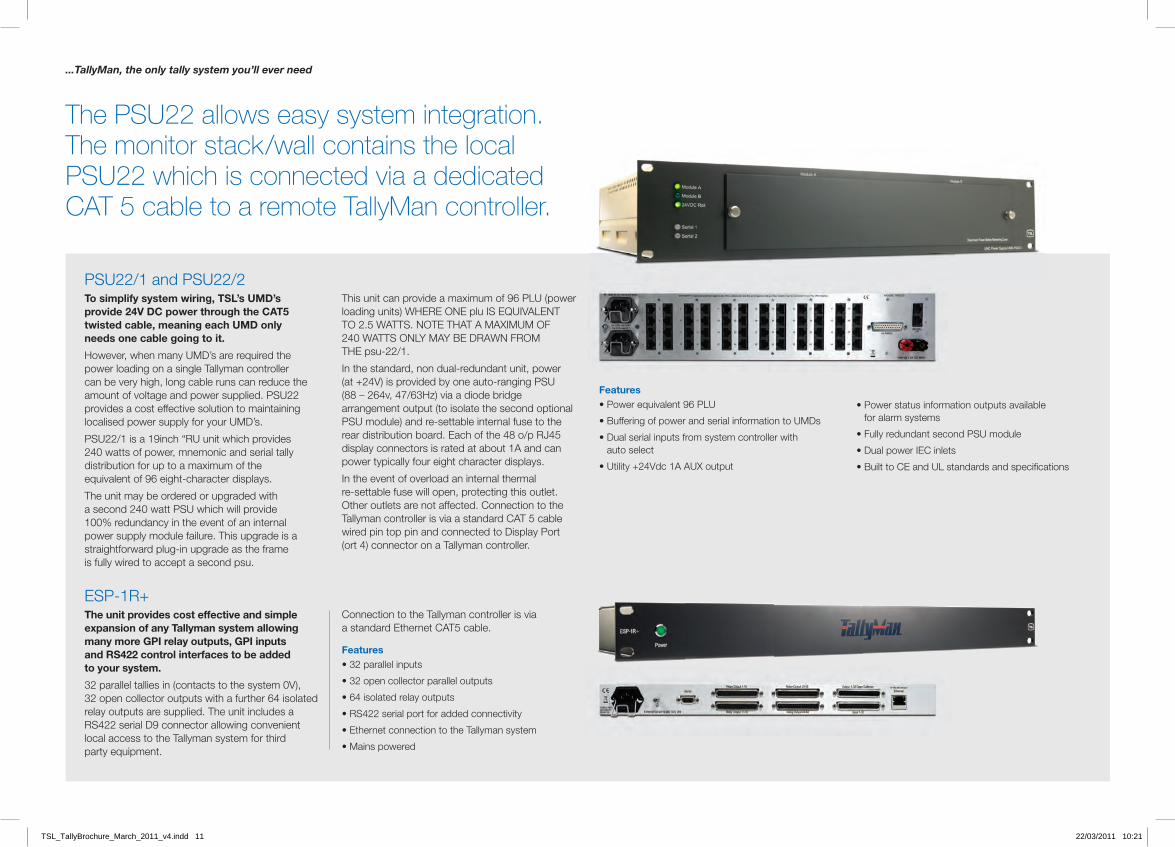
The PSU22 allows easy system integration. The monitor stack/wall contains the local PSU22 which is connected via a dedicated CAT 5 cable to a remote TallyMan controller.
PSU22/1 and PSU22/2To simplify system wiring, TSL’s UMD’s provide 24V DC power through the CAT5 twisted cable, meaning each UMD only needs one cable going to it.
However, when many UMD’s are required the power loading on a single Tallyman controller can be very high, long cable runs can reduce the amount of voltage and power supplied. PSU22 provides a cost effective solution to maintaining localised power supply for your UMD’s.
PSU22/1 is a 19inch “RU unit which provides 240 watts of power, mnemonic and serial tally distribution for up to a maximum of the equivalent of 96 eight-character displays.
The unit may be ordered or upgraded with a second 240 watt PSU which will provide 100% redundancy in the event of an internal power supply module failure. This upgrade is a straightforward plug-in upgrade as the frame is fully wired to accept a second psu.
ESP-1R+The unit provides cost effective and simple expansion of any Tallyman system allowing many more GPI relay outputs, GPI inputs and RS422 control interfaces to be added to your system.
32 parallel tallies in (contacts to the system 0V), 32 open collector outputs with a further 64 isolated relay outputs are supplied. The unit includes a RS422 serial D9 connector allowing convenient local access to the Tallyman system for third party equipment.
This unit can provide a maximum of 96 PLU (power loading units) WHERE ONE plu IS EQUIVALENT TO 2.5 WATTS. NOTE THAT A MAXIMUM OF 240 WATTS ONLY MAY BE DRAWN FROM THE psu-22/1.
In the standard, non dual-redundant unit, power (at +24V) is provided by one auto-ranging PSU (88 – 264v, 47/63Hz) via a diode bridge arrangement output (to isolate the second optional PSU module) and re-settable internal fuse to the rear distribution board. Each of the 48 o/p RJ45 display connectors is rated at about 1A and can power typically four eight character displays.
In the event of overload an internal thermal re-settable fuse will open, protecting this outlet. Other outlets are not affected. Connection to the Tallyman controller is via a standard CAT 5 cable wired pin top pin and connected to Display Port (ort 4) connector on a Tallyman controller.
Connection to the Tallyman controller is via a standard Ethernet CAT5 cable.
Features• 32 parallel inputs
• 32 open collector parallel outputs
• 64 isolated relay outputs
• RS422 serial port for added connectivity
• Ethernet connection to the Tallyman system
• Mains powered
Features• Power equivalent 96 PLU
• Buffering of power and serial information to UMDs
htiw rellortnoc metsys morf stupni laires lauD •auto select
• Utility +24Vdc 1A AUX output
elbaliava stuptuo noitamrofni sutats rewoP •for alarm systems
• Fully redundant second PSU module
• Dual power IEC inlets
...TallyMan, the only tally system you’ll ever need
TSL_TallyBrochure_March_2011_v4.indd 11 22/03/2011 10:21

The TSL range of displays complements the TallyMan controller range. They offer clear, bright (but dimmable) mnemonics with comprehensive tally indications.
TSL offers a range of displays, including a static eight-character display where the characters are printed onto a photographic film (“legend”); an eight-character tri-colour display that uses 17.5mm high; 7x5 dot-matrix display blocks; a sixteen character version; a twin eight character version (dual display); and miniature triple and quad displays.
The Static S8C Display
This module’s eight-character display requires panel mouting. Separately addressable tally LEDS are red only.
The display module consists of red and green LEDs that edge-light a panel behind an eight-character film message. This film message is known as a “legend”, which can be replaced from the front of the unit. If desired, a clear filter can be placed in front of the legend to retain it.
Power is normally provided by a TMx Controller or “stared” out from a PSU-22 Power Supply Unit using CAT 5 cable. Both power and serial data are carried by the CAT 5 cable.
Tally LEDs (red) are provided to the left and right of the message area. If required these tally lamps can be operated independently.
On-board voltage regulation is provided and the units are designed to operate from a nominal +24 volt supply. The usual power source is from a TM1 controller or from the TSL UMD PSU-22/1 power unit.
Dynamic Displays
D8C, DD8C and D16C displays use tri-colour display blocks 17.5mm high. The D8C display needs to be mounted onto a panel whereas the dual eight-character (DD8C) and 16-character displays (D16C) are built into a standard 19” case. The separately addressable tally LEDs either side of the display blocks are also tri-colour.
All displays are designed to operate from an external power source (nominal +24v DC), which is fed to the RJ45 serial connector on the rear panel.
Power is normally provided by a TMx Controller or “stared” out from a PSU-22 Power Supply Unit using CAT 5 cable. Both power and serial data are carried by the CAT 5 cable.
The TD8 and QD8 displays are green only with twin red tally LEDS per display in a 19” case.
Displays
11
TSL_TallyBrochure_March_2011_v4.indd 12 22/03/2011 10:21

A rapid switching feature on the TSL Tallyman allows control to be switched between the different live facilities with a single touch screen command
TSL_TallyBrochure_March_2011_v4.indd 14 22/03/2011 10:21
TallyMan Virtual Panel Universal Equipment Control for Frontline Operators
Designed to simplify controls of multiple routers I/Os, the TallyMan VP touchscreen intuitive user interface is engineered to be more in tune with the needs of creative operators such as Directors, Producers, EVS and Graphics positions. Ideal for: News OperationsSporting EventsRemote head-ends
• Straight-forward addition to existing TallyMan systems.• Removes the need to install multiple hardware panels to provide varied functionality and replacement panels during future upgrades. • Interfaces with ANY third-party router, vision mixer or multiviewer.• Provides universal control for frontline operators who don't need to know information about source paths etc.• Simple touchscreen drag-and-drop editing.• Heightened security for positions with limited functionality.• Remote switch-off available. TallyMan provides a seamless communication path, communicating with vision mixers and routers to provide real time mnemonic and tally automationto cameras and monitor walls. TallyMan can configure all hardware components within a system to the user's preferences via the easy mapping of tallies, mnemonics and router paths for simple drag-and-drop editing.
...TallyMan, the only tally system you'll ever need

Problem: How to quickly and seamlessly switch operational positions from Studio A to Studio B
Case Study
Seamless switching between studio’s provides full redundancy for transmission and allows roving cameras to be assigned to either gallery at the touch of a button. An assignable camera might be located in a remote location within the complex that could be used by either studio, for example one used to broadcast from an outside cooking area.
Traditionally, an engineer would have to individually route the video and audio feeds from the camera to the correct studio, and provide the reverse feed, talkback communications and red light tallies to the camera using a complicated arrangement of router assignments, patch panel plugging and tally configurations.
TSL created a touch screen GUI to interface to Tallyman, which in turn controls the sound and vision mixers, routers and data communications, to easily and virtually instantaneously provide all the routing and control at the touch of a single button. This made a significant improvement to the efficiency and flexibility of the facility.
If a transmission-critical piece of equipment, such as the vision mixer, were to fail, this application can be used to restore service instantly by automatically routing all of the video, audio, tally and communication feeds to the corresponding piece of equipment in the other studio.
For example, if the vision mixer in Studio A fails, the Studio Technical Manager can press one button on the Tallyman Touch Screen control to send a series of pre-programmed commands to the necessary vision mixers, routers and talkback routers to completely by-pass the Studio A vision mixer and instead make Studio B’s vision mixer live into Studio A. The operator would move into Studio B and all of the vision feeds, monitor feeds, tallies and talkback circuits would be available to them, virtually instantaneously, allowing the broadcast to continue and emergency repairs to the vision mixer to be carried out.
Traditionally, this could have taken a team of highly experienced engineers many minutes to provide, and TSL’s cost-effective solution using state of the art Tallyman TMC1 and touch screen technology provides real savings in times of crisis and seamless management of television studios for normal operation.
Future adaptability is straightforward as the Touch Screen software can easily be changed using XML configuration files. Tallyman is constantly being updated to provide the most up-to-date drivers to support the protocols of vision mixers, routers etc.
PC Touch Screen control.
Sound Desk A/V Router
Studio 1 Touch Screen Monitor
Ethernet Router Data Control Router
Studio 2 Touch Screen Monitor
Lighting Desk
TMC1 Tallyman Controller
TSL_TallyBrochure_March_2011_v4.indd 13 22/03/2011 10:21
13

Core Video Router
TX Router
CR1 PGMEmbedder
CR2 PGMEmbedder
AES AudioRouter
RS422Router
Multiple Studios
Live Control Rooms
Tallyman SelectedControl Room
Camera Monitoring
Control Room Mix-MinusFeed to Comms Matrix
TallymanSelected
RCP
ControlRoom
ProgramAudio to
AES Router
TallymanSelected
PGMAudio to
Embedder
Tallyman ControlledPGM Output
PGM Output
PGM + Audio
Tallyman ControlRouter Controller
Tallyman ControlRouter Controller
Tallyman Control
All Cameras Feed to bothControl Room Vision Mixers
TallymanControl
Tallyman ControlledStudio Monitoring
Tallyman ControlRouter Controller
TallymanControl
ControlRoomPGM
Output
CameraVideofrom
Studios
Intercom System
TSL TallymanSystem Controller
Camera CCU’s
Router ControllerControl RoomVision Mixers
Control Room 1Monitors
Control Room 1Camera RCP’s
Control RoomAudio
TSL TallymanUser Interfaces
Control RoomCamera Routers
Video
Key
Audio
Control
TSL Tallyman System
Case Study
Control Room User interfacesTallyman system interacts with the router control system and comms matrix. This permits multiple operator specific Video, Audio and Data routing via a single touch of a use-friendly interface.
Single action on Tallyman touchscreen user interface allows:
Operator Selection:
• Swaps any of the operator positions with identical position in second Control Room
• Routes monitoring to allow for position change
• Routes talkback to allow for position change
• Displays status of Control Room on multiviewer
Camera Selection:
• to non specific CCU
• Shows choice of RCP camera monitoring on Control Room multiviewers
• Links choice of Control Room camera with relevant router sources
Camera Preset:
• Recall or Store a studio camera set-up for individual programs
• Makes all camera monitoring routes and RCP allocations for all selected camera in one action
TSL_TallyBrochure_March_2011_v4.indd 15 22/03/2011 10:21

TSL_TallyBrochure_March_2011_v4.indd 16 22/03/2011 10:21

Global reseller network
TSL Professional Products Ltd has a network of distributors supporting our products all over the world.For further details about our product range and where to buy please visit www.tsl.co.uk/products
TSL Sales: +44 (0)1628 676 221 E-mail: [email protected] Web: www.tsl.co.uk/products
TSL Professional Products Ltd, Units 1&2, First Avenue, Globe Park, Marlow, SL7 1YA, United KingdomTel: +44 (0)1628 676 221 Fax: +44 (0)1628 676 299 E-mail: [email protected]
Speci� cations subject to change without notice. © 2012 TSL Professional Products Ltd. All rights reserved.ALL TSL monitoring products are fully compliant with RoHS and WEEE regulations.
PROFESSIONALPRODUCTS GROUP
PROFESSIONALPRODUCTS LTD
TSL_TallyBrochure_March_2011_v4.indd 1 22/03/2011 10:21