Embed Size (px)
Citation preview
Compurrs & Strucrures Vol. 32, No. 5, pp. 9%962, 1989 Printed in Great Britain.
CO45-7949/89 13.00 + 0.00 0 1989 Maxwell Pcrgamon Macmillan plc
TAP-86: A THREE-DIMENSIONAL FRAME ANALYSIS PROGRAM FOR TALL BUILDINGS
CA0 LI
The Ninth Design and Research Institute, Shanghai, China
(Received 4 May 1988)
Abstract--TAP-86 Program has three unique features: (1) the use of thin-wall element with opening for analyzing the torsion and warping effect of shear walls under lateral loads; (2) the use of three-dimensional analysis method for calculating the deformation and member forces of tall building structures under lateral and vertical loads; (3) the use of three kinds of dynamic analysis of structures, the plane vibration method for symmetric structures, the one direction seismic wave input method and the two direction seismic waves simultaneously input method for unsymmetric structures where the torsion-couple vibration effect should be taken into account. TAP-86 Program can be used to analyze such tall building systems as space frames, shear walls and tubular structures under static and seismic loads, and to calculate the member forces and reinforcements of beams, columns and shear walls. The program is written in FORTRAN 77 and runs on IBM-4341 and IBM-3031 computers.
1. INTRODUCTION
In designing high-rise buildings, if the building struc- ture is asymmetric, if there is eccentric loading or if there exist many non-planar shear walls in the struc- ture, it is necessary to use a three-dimensional struc- ture analysis method in order to get more accurate results. It may be very difficult to use plane structure analysis to solve this sort of problem.
TAP-86 Program is a three-dimensional frame analysis program for tall buildings. There are only two sorts of basic member elements in the program, i.e. a space rectangular beam element and a thin-wall column element. But the program is effective and powerful for structural engineers to use easily in analyzing high-rise building structures under lateral and vertical loads.
On the other hand, there are three kinds of dy- namic analysis of structures in the program, i.e. the plane vibration method for symmetric structures, the one direction seismic wave input method and the two direction seismic waves simultaneously input method for unsymmetric structures where the torsion-couple vibration effect should be taken into account. In this way, structural engineers can choose different dy- namic analysis methods according to the regularity of structures.
TAP-86 Program also calculates the reinforce- ments of beams, columns and shear walls according to the structural responses under static and dynamic loads.
2. STATIC ANALYSIS OF STRUCTURES
2.1. Basic member elements
Every kind of structural component in a high-rise building can be defined as following four kinds of member elements:
(1) Beam element-the horizontal floor member connecting with columns at two ends.
(2) Connecting beam element-the horizontal floor member connecting with shear walls at one or two ends.
(3) Column element-the vertical member in a structure.
(4) Thin-wall column element-the vertical member comprised of several plane shear walls.
The stiffness matrix of space rectangular beams can be used as that of beam elements, column elements and connecting beam elements. The difference be- tween beam and column elements is only the direction of coordinate axes.
Usually, the number of degrees of freedom of a space beam is twelve, including bending, shear and torsion. The vectors of member force {f} and defor- mation {d} of a space beam can be expressed as the following eqns, respectively,
{~}=[Nx,,NY,,Nz,,~x,,~Y,,~~,,Nx~,NY,,
Nz2, Mx,, MY,, JWT
{d) = b,, Ul, WI, ox,, OY,, oz,, u2,02, w2,ox,,
OY2, Oz21T.
The subscripts 1 and 2 represent the left and right ends of a beam element.
The stiffness matrix of a space beam can be ob- tained according to the relationship between {J} and {d}, i.e.
0-j= WIW.
The stiffness matrix [Kb] can be found in many reference texts.
953
954 CA0 LI
A shear wall between two consecutive floors can be represented by a thin-wall column element. For ex- ample, the commonly used E-, H- or U-shaped open section arrangement of the core walls can be treated as thin-wall columns in this way. Usually, the thin- wall column element would warp under twist. The torsion angle’s derivative Oz’ = dOz/dr caused by section warping is called warping angle. After intro- ducing warping angle Oz’ and warping moment B to the vectors of member forces and deformations, a thin-wall column element has fourteen degrees of freedom as shown in the following eqns
{f}=[Nx,,Ny,,Nz,,Mx,,My,,Mz,,B,,Nx,,
Ny2, Nz,, Mx2, My2, Mz,, B21=
(4 = b,, 01, ~1, Ox,, OY,, Oz,,, ~2,029 w2,Ox2,
oy, oz,, Oz,.]?
The stiffness matrix [Kc] of a thin-wall column el- ement is similar to that of a space beam element. The difference between the two sorts of elements is that [Kb] is a 12 x 12 matrix and [Kc] is a 14 x 14 matrix.
2.2. Transformation matrices for elements
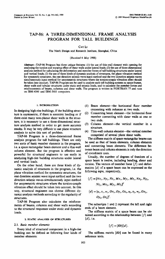
In analyzing high-rise building structures, a global coordinate system should be set up in order to represent the locations of every frame element. The transformation from a local coordinate system to a global coordinate system should be. carried out before the overall stiffness matrix of a structure can be obtained. If the angle between the axes of two coordinate systems is A, as shown in Fig. 1, the coordinate transformation matrix [ZJ is
where
cos A
-sin A [Tll= 0
sinA 0
cosA 0 0
0 1
cos A
0 -sinA
0
sin A 0
cosA 0
0 1
The subscripts 1 and 2 represent the upper and bottom ends of a thin-wall column element. If there are rigid arms at the ends of a member
According to Vlasov’s thin-walled beam theory, element, the transformation of rigid arms should be
the relationship between torque, warping moment carried out. The beam element has the rigid arms as
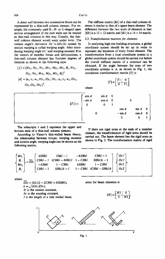
and torsion angle, warping angle can be shown as the shown in Fig. 2. The transformation matrix of rigid
following matrix,
Chkl - 1 - kSHk1 CHkl - 1
ICHkl - SHkl/l 1 - CHkl SHkl/k - 1
I- CHkl kSHkl I- CHkl
SHkllk - I 1 - CHkl ICHkl - SHkljk
where zz = GIz/(2 - 2CHkl+ klSHkl), k = ,/(GIz/Elw), Iz is the torsion constant,
I is the length of a thin walled beam.
arms for beam elements is
Iw is the warping constant,
0 X Fig. 1.
A three-dimensional frame analysis program 955
j/, I_dk,
0 I 2 X Length
Fig. 2.
where
1 1
-dj
1
[H2] =
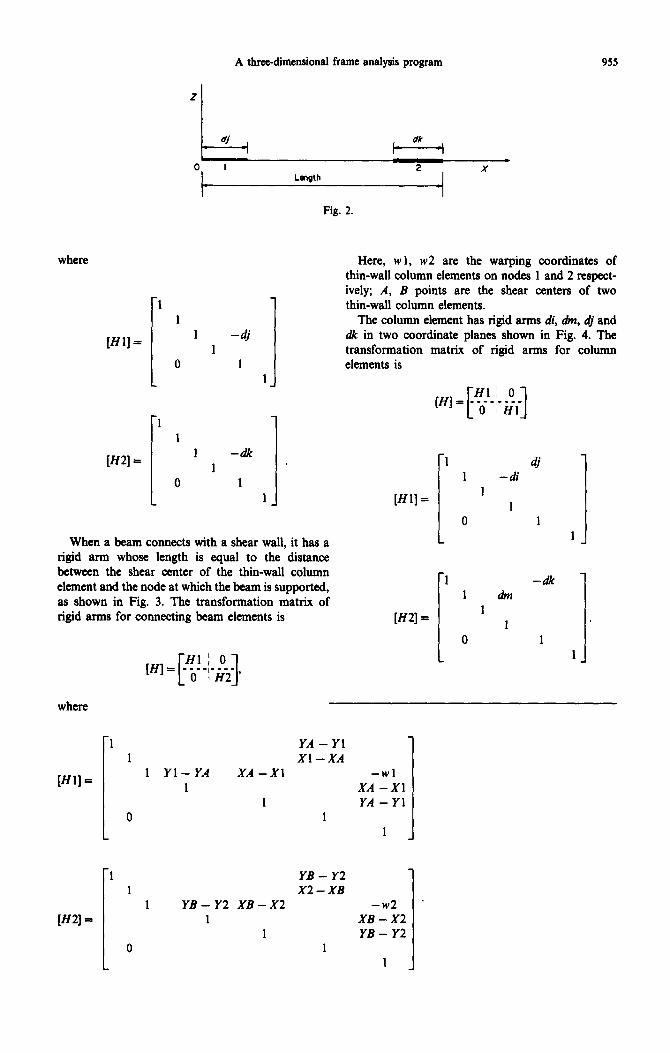
When a beam connects with a shear wall, it has a rigid arm whose length is equal to the distance between the shear center of the thin-wall column element and the node at which the beam is supported, as shown in Fig. 3. The transformation matrix of rigid arms for connecting beam elements is
Here, w 1, w2 are the warping coordinates of thin-wall column elements on nodes 1 and 2 respect- ively; A, B points are the shear centers of two thin-wall column elements.
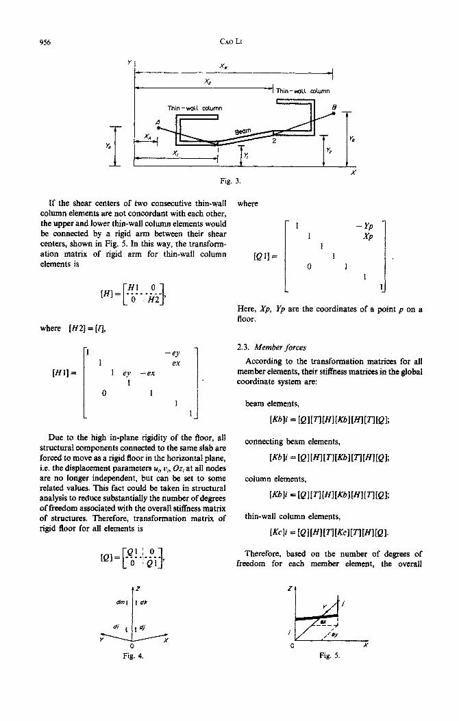
The column element has rigid arms di, ah, t# and dk in two coordinate planes shown in Fig. 4. The transformation matrix of rigid arms for column elements is
WI = Hl; 0
[ 1 _ 0 -I-iii
[Hl] =
[H2] = I 1 0 1 1 drill 1 -& 1 1
where
1 YA - Yl 1 Xl -XA
(Hl] = 1 Yl-YA XA -Xl -wl
1 XA -Xl 1 YA - Yl
0 1 1
[H2] =
1 YB - Y2 1 X2-XB
1 YB-Y2 XB-X2 -w2 * 1 XB-x2
1 YB - Y2 0
1
956 CA0 Ll
x, -I *
W Thin-wall column
If the shear centers of two consecutive thin-wall column elements are not concordant with each other, the upper and lower thin-wall column elements would be connected by a rigid arm between their shear centers, shown in Fig. 5. In this way, the transform- ation matrix of rigid arm for thin-wall column elements is
where [H2] = [I],
X
Fig. 3.
[HI] =
I -9 1 ex
1 ey -en 1
0 1 1
1
Due to the high in-plane rigidity of the tloor, all structural components connected to the same slab are forced to move as a rigid floor in the horizontal plane, i.e. the displacement parameters u,, u, Oz, at all nodes are no longer independent, but can be set to some related values. This fact could be taken in structural analysis to reduce subs~n~ally the number of degrees of freedom associated with the overall stiffness matrix of structures. Therefore, transformation matrix of rigid floor for all elements is
[Q]= !$!_;-&s, [ 1
0
Fig. 4.
where
1 - YP 1 XP
1 [QU= 1
0 1 1
1
Here, Xp, Yp are the coordinates of a point p on a floor.
2.3. Member forces
According to the transformation matrices for all member elements, their stiffness matrices in the global coordinate system are:
beam elements,
Kbli = ~Q1I~~~1~~~1~~1~T3~Ql~
connecting beam elements,
Wli = tQl~~lI~lt~~l~3i7~~l~Ql;
column elements,
Kbli = ~Ql~T3~~I~~~l~~l~TlIQl;
thin-wall column elements,
Nli = ~Ql~~l~~l~~~l~T7~~l~Ql.
Therefore, based on the number of degrees of freedom for each member element, the overall
Fig. 5.
A three-dimensional frame analysis program 951
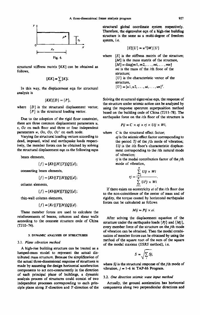
Y
l-l P* T Y=
o- X
t X?
4 Fig. 6.
structural global coordinate system respectively. Therefore, the eigenvalue eqn of a high-rise building structure is the same as a multi-degree of freedom system, i.e.
structural stiffness matrix [KK] can be obtained as follows,
where [S] is the stiffness matrix of the structure; [M] is the mass matrix of the structure, [M]=diag[ml,m2,. . .,mi,. . . ,mn] mi is the mass of the ith floor of the structure;
[KK] = c [K]i. {U} is the characteristic vector of the , structure,
In this way, the displacement eqn for structural analysis is
(U}=[ul,u2 ,..., ui ,..., unlT.
where (D} is the structural displacement vector; {P} is the structural loading vector.
Due to the adoption of the rigid floor constraint, there are three common displacement parameters U, v, Or on each floor and three or four independent parameters w, Ox, Oy, Oz’ on each node.
Varying the structural loading vectors according to dead, imposed, wind and earthquake loads respect- ively, the member forces can be obtained by solving the structural displacement eqn as the following eqns
Solving the structural eigenvalue eqn, the response of the structure under seismic action can be analyzed by using the response spectrum superposition method based on the building code of China (TJl l-78). The earthquake force on the ith floor of the structure is
Pij = C x aj x rj x Vii x Wi,
where
beam elements,
if} = [~~lWlPl~Ql~4;
connecting beam elements,
U-1 = WlP’ll[fJl[QlV~~
column elements,
C is the structural effect factor; uj is the seismic effect factor corresponding to the period Tj of the jth mode of vibration; Uij is the ith floor’s characteristic displace- ment corresponding to the ith natural mode of vibration; rj is the modal contribution factor of the jth mode of vibration,
i Uij x Wi
rj = 'N'
C Ui’j x Wi i-l
thin-wall column elements,
U-1 = ~~clP’ll[~l[Ql~4.
If there exists an eccentricity ei of the ith floor due to the non-coincidence of the center of mass and of rigidity, the torque caused by horizontal earthquake forces can be calculated as follows
These member forces are used to calculate the reinforcements of beams, columns and shear walls according to the concrete structure code of China (TJlO-74).
Mij=Pijxei.
3. DYNAMIC ANALYSIS OF !3TRUCWRES
3.1. Plane vibration method
After solving the displacement equation of the structure under the earthquake loads { Pj} and {Mj}, every member force of the structure on the jth mode of vibration can be obtained. Then the modal combi- nation of member forces can be obtained by using the method of the square root of the sum of the square of the modal maxima (SSRS method), i.e.
A high-rise building structure can be treated as a lumped-mass model to represent the actual dis- tributed mass structure. Because the simplification of the actual three-dimensional response of structures is made by assuming the design horizontal acceleration components to act nonconcurrently in the direction of each principal plane of buildings, a dynamic analysis process of structures could consist of two independent processes corresponding to each prin- ciple plane along X-direction and Y-direction of the
I s= pj, J i
where Sj is the structural response of the jth mode of vibration, j = 16 in TAP-86 Program.
3.2. One direction seismic wwe input method
Actually, the ground acceleration has horizontal components along two perpendicular directions and
958 CA0 LI
a vertical component. Usually, the rotational compo- nents of earthquake ground motion are negligible. Because most building structures are more sensitive to horizontal or lateral distortions, it has been the practice in most instances to consider only the struc- tural response of the horizontal components of ground motion. The effects of the vertical component of ground motion have generally not been considered significant enough to merit special attention.
However, due to the horizontal components of ground motion, torsional effects in structures do occur, as a result of ground compliance and the non-coincidence of the centers of mass and rigidity. Based on the study of dynamic torsional effects in multistorey structures where this effect is more pro- nounced, it is necessary to use a three-dimensional dynamic analysis method to analyze the seismic response of high-rise building structures.
When considering the torsion-coupled vibration of structures, there are three degrees of freedom (two horizontal displacement and one rotation) at each floor, and the total number of degrees of freedom for a structure of N floors is 3N. Therefore, the stiffness matrix of a structure could be obtained as follows,
The element Sij in [S] (i = 1,2,. . . ,3N, j=l,2,..., 3N) represents the amount of horizontal action or torque on the jth floor to produce the unit displacement on the ith floor of a structure.
If the acceleration iig of one direction seismic wave and input angle B have been decided in advance (Fig. 7), the dynamic equation of the structure is
WI{ U} + PI{ 01 = -Pfl WI&,
where
{V} =[Xl,X2,. . . ,xn, Yl, Y2,. . .) Yn,
0 1,02, . . . ) On]‘;
[M]=diag[ml,m2 ,..., mn, ml,m2 ,..., mn,
Jl, J2,. . . , Jn].
mi, Ji is the mass and moment of inertia of the ith floor of the structure;
[Bb] = {{sin B}n x 1, {cos B}n x 1, {O}}.
yt . iig ki 8
0 X Fig. 7.
The vector matrix [V] of the structure can be obtained by solving the eigenvector equation
where
[VI = [{Vl), {W,. * * 9 {vj), *. . , {Un)l
and
{Vj}=[xjl,xj2,.. ..,xjtl, yjl, yj2 ,**...., yin,
Oj l,Oj2, . . . . , Ojn]‘.
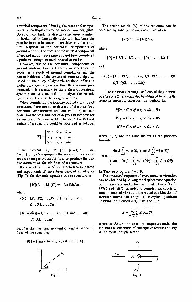
The ith floor’s earthquake forces of thejth mode of vibration (Fig. 8) can also be obtained by using the response spectrum superposition method, i.e.
Pijx = C x aj x rj x Xij x Wi
Pgy = C x aj x rj x Yij x Wi
Mij=CxajxrjxOijxJi,
where C, aj are the same factors as the previous formula,
N N
sinB~mixXij+cosB~mixYij
rj= N i-l i-l
N N
~mixX?j+~mixYi2j+~JixOitj i-1 i-l i-1
In TAP-86 Program, j = l-9. The structural response of every mode of vibration
can be obtained by solving the displacement equation of the structure under the earthquake loads {Pjx}, {Pjy } and {Mj}. In order to consider the effects of torsion-coupled vibration, the modal combination of member forces can adopt the complete quadrate combination method (CQC method), i.e.
S = L-7
c 1 SJ PkJ Sk,
where Sj, Sk are the structural responses under the jth and the kth mode of earthquake forces; and Pkj is the modal couple factor;
Y
P,X
&- - 4, 0
X
F?,x I
Fig. 8.
Pkj = (1
8 x h*(l + r)r3’* safety. In this way, the most disadvantageous input
- r*)* + 4 x !I*(1 + r2)r angle of seismic wave is not needed to be considered when the dynamic response of a structure is being
h = 0.05, r = Tk/Tj, analyzed. This method is more suitable to designing structures whose shapes are very irregular.
Tk, Tj are the periods of the kth and the jth mode of vibration of the structure.
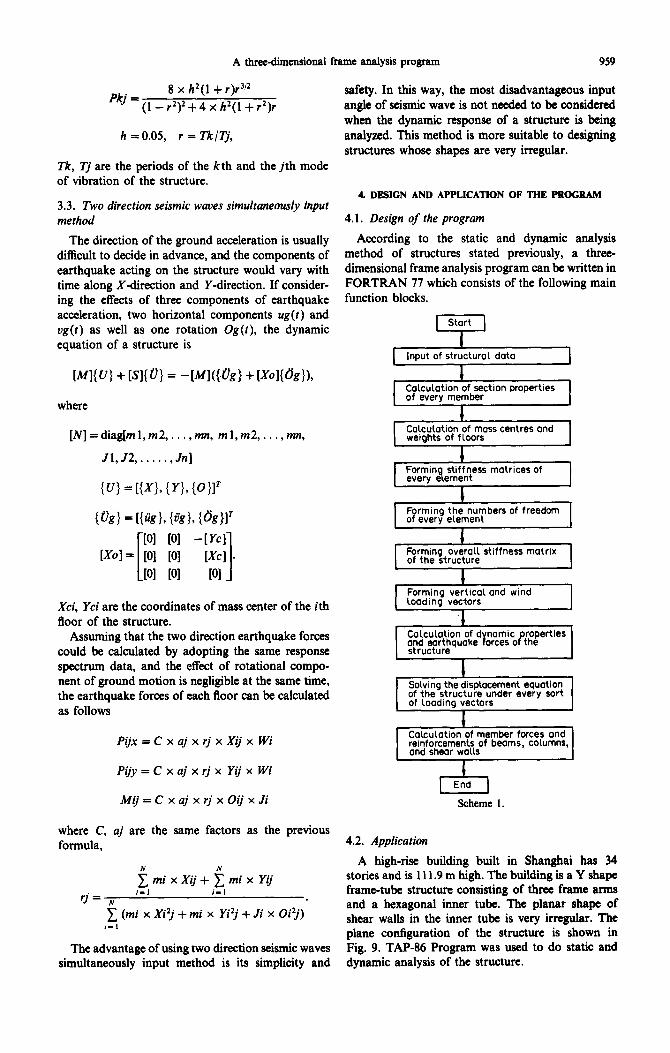
4. DESIGN AND APPLICATION OF THE PROGRAM 3.3. Two direction seismic waves simultaneously input method 4.1. Design of the program
The direction of the ground acceleration is usually According to the static and dynamic analysis
difficult to decide in advance, and the components of method of structures stated previously, a three-
earthquake acting on the structure would vary with dimensional frame analysis program can be written in
time along X-direction and Y-direction. If consider- FORTRAN 77 which consists of the following main
ing the effects of three components of earthquake function blocks.
acceleration, two horizontal components ug(t) and ug(t) as well as one rotation Og(t), the dynamic I equation of a structure is
Input of structural data I I
j”‘““’ Calculation of section properties
where t
[N]=diag[ml,m2 ,..., mn, ml,m2, .,m, Calculation of mass centres and weiahts of floors
J1,32 ,....., Jn]
VW = r{&!}, @g>, ml’ PI 101 -[Ycl
1x01 = 101 [Ol
[ 1 WC1 . PI PI PI
Forming overall stiffness matrix 1-1 Forming vertical and wind
Xci, Yci are the coordinates of mass center of the ith floor of the structure.
Assuming that the two direction earthquake forces could be calculated by adopting the same response spectrum data, and the effect of rotational compo- nent of ground motion is negligible at the same time, the earthquake forces of each floor can be calculated as follows
Pijx = C x aj x rj x Xij x Wi reinforcements of beams, COlumnS,
Pijy = C x aj x rj x Yij x Wi 1 End 1
Mij=CxajxrjxOijxJi Scheme 1.
where C, aj are the same factors as the previous formula, 4.2. Application
N N A high-rise building built in Shanghai has 34
CmixXij+CmixYij stories and is 111.9 m high. The building is a Y shape
rj= y i-l i-1 frame-tube structure consisting of three frame arms
,$ (mi x Xiv + mi x Yifi + Ji x Oi2j) and a hexagonal inner tube. The planar shape of shear walls in the inner tube is very irregular. The plane configuration of the structure is shown in
The advantage of using two direction seismic waves Fig. 9. TAP-86 Program was used to do static and simultaneously input method is its simplicity and dynamic analysis of the structure.
A three-dimensional frame analysis program 959
loading vectors
I Calculation of d namic roperties VP I and earthauake orces o the
structure ’ I I
I Solving the displacement equation of the structure under every sort of loading vectors I
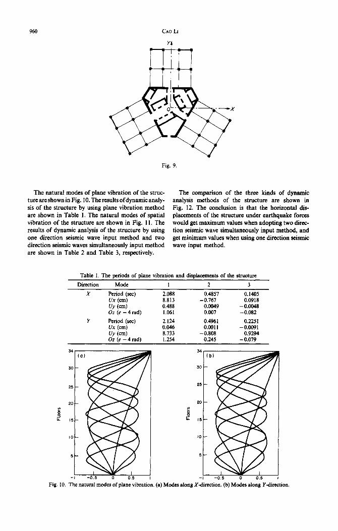
960 CA0 LI
Fig. 9.
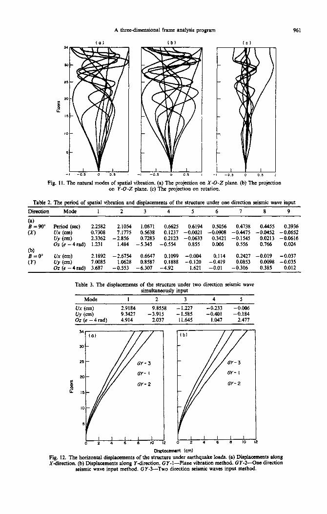
The natural modes of plane vibration of the struc- ture are shown in Fig. 10. The results ofdynamic analy- sis of the structure by using plane vibration method are shown in Table 1. The natural modes of spatial vibration of the structure are shown in Fig. 11. The results of dynamic analysis of the structure by using one direction seismic wave input method and two direction seismic waves simultaneously input method are shown in Table 2 and Table 3, respectively.
The comparison of the three kinds of dynamic analysis methods of the structure are shown in Fig. 12. The conclusion is that the horizontal dis- placements of the structure under earthquake forces would get maximum values when adopting two direc- tion seismic wave simultaneously input method, and get minimum values when using one direction seismic wave input method.
Table 1. The ueriods of plane vibration and displacements of the structure
Direction Mode 1 2 3
x Period (XC) 2.088 0.4857 0.1405 Ux (cm) 8.813 -0.767 0.0918 UY (cm) 0.488 0.0049 -0.0048 Oz (e - 4 rad) 1.061 0.007 -0.082
Y Period (set) 2.124 0.4961 0.2251 Ux (cm) 0.046 0.0011 -0.0091 UY (cm) 8.733 -0.808 0.9294 Oz (e - 4 rad) 1.254 0.245 - 0.079
Fig. 10. The natural modes of plane vibration. (a) Modes along Xdirection. (b) Modes along Y-direction.
A three-dimensional frame analysis program 961
(of T
(
/
\
-1
fbf
L
-,
Fig. 11. The natural modes of spatial vibration. (a) The projection on X-O-Z plane. (b) The projection on Y-O-Z plane. (c) The projection on rotation.
Table 2. The period of spatial vibration and displacements of the structure under one direction seismic wave input
Direction Mode 1 2 3 4 5 6 I 8 9
(4 B-90" Period (SW) 2.2582 2*1054 1.0671 0.6625 0.6194 0.5056 0.4738 0.4455 0.3936 (XI f.Jx (Qn) 0.7308 7.1775 0.5638 0.1237 -0.0021 -0.0908 -0.4475 -0.0452 -0.0652
0 (cm) 2.3362 -2.856 0.7283 0.2123 -0.0633 0.3421 -0.1545 0.0213 -0.0616 Oz (e -4rad) 1.231 1.484 - 5.345 -0.554 0.855 0.006 0.556 0.766 0.024
(b) B=O ux WI 2.1892 - 2.6754 0.6641 0.1099 -0.004 0.114 0.2427 -0.019 -0.037 (Y) UY (cm) 7.0085 1.0628 0.8587 0.1888 -0.120 -0.419 0.0853 0.0098 -0.035
Or (e - 4 radl 3.687 -0.553 -6.307 -4.92 1.621 -0.01 -0.306 0.385 0.012
Table 3. The displacements of the structure under two direction seismic wave simultaneously input
Mode 1 2 3 4 S
tJx (cm) 2.9184 9.8558 - 1.227 -0.233 -0.006 WV (cmf 9.3427 -3.915 - 1.585 -0.401 -0.184 Or (e - 4 rad) 4.914 2.037 11.645 1.047 2.477
Di#acament (cm) Pig. 12. The horizontal displacements of the structure under earthquake loads. (a) Displacements along X-direction. (b) Displacements along Y-direction. GY-l-Plane vibration method. GY-2-One direction
seismic wave input method. GY-~-TWO direction seismic waves input method.
962 CA0 LI
5. CONCLUSION using TAP-86 Program. TAP-86 Program has been used in more than ten design projects in China since
TAP-86 Program is a three-dimensional frame 1986 analysis program especially suitable to high-rise ’ building structures, and easier to use in this subject than general structural analysis programs. The Acknowledgements-The research project of developing
periods of vibration, displacements and the distri- TAP-86 Program began in 1985 and ended in 1987. My
bution of shear forces of a structure under static colleague, Mr Xu Rong, did a great deal of work on the project. We also got a lot of help from the Mathematics
and dynamic loads can be obtained accurately by Department of East-China Normal University.