Embed Size (px)
Citation preview

8/18/2019 taskalfa_220
http://slidepdf.com/reader/full/taskalfa220 1/300
SERVICEMANUAL
Published in October 2009
842KL113
2KLSM063
Rev.3
TASKalfa 180
TASKalfa 220
loaded from www.Manualslib.com manuals search engine
8/18/2019 taskalfa_220
http://slidepdf.com/reader/full/taskalfa220 2/300
CAUTION
RISK OF EXPLOSION IF BATTERY IS REPLACED BY AN INCORRECT TYPE. DISPOSE OFUSED BATTERIES ACCORDING TO THE INSTRUCTIONS.
It may be illegal to dispose of this battery into the municipal waste stream. Check with your local
solid waste officials for details in your area for proper disposal.
ATTENTION
IL Y A UN RISQUE D’EXPLOSION SI LA BATTERIE EST REMPLACEE PAR UN MODELE DE
TYPE INCORRECT. METTRE AU REBUT LES BATTERIES UTILISEES SELON LES INSTRUC-
TIONS DONNEES.
Il peut être illégal de jeter les batteries dans des eaux d’égout municipales. Vérifiez avec les fonc-
tionnaires municipaux de votre région pour les détails concernant des déchets solides et une mise
au rebut appropriée.
loaded from www.Manualslib.com manuals search engine

8/18/2019 taskalfa_220
http://slidepdf.com/reader/full/taskalfa220 3/300
Revision history
Revision Date Replaced pages Remarks
1 August 31, 2009 1-2-10, 1-2-11, 1-2-13, 1-3-2, 1-3-3, 1-3-17, 1-3-47,
1-5-2, 1-5-13
-
2 September 26, 2009 Contents, 1-6-3 -
3 October 22, 2009 2-4-1 to 2-4-4 -
loaded from www.Manualslib.com manuals search engine

8/18/2019 taskalfa_220
http://slidepdf.com/reader/full/taskalfa220 4/300
This page is intentionally left blank.
loaded from www.Manualslib.com manuals search engine

8/18/2019 taskalfa_220
http://slidepdf.com/reader/full/taskalfa220 5/300
Safety precautions
This booklet provides safety warnings and precautions for our service personnel to ensure the safety of their customers, their machines as well as themselves during maintenance activities. Service personnel
are advised to read this booklet carefully to familiarize themselves with the warnings and precautions
described here before engaging in maintenance activities.
loaded from www.Manualslib.com manuals search engine
8/18/2019 taskalfa_220
http://slidepdf.com/reader/full/taskalfa220 6/300
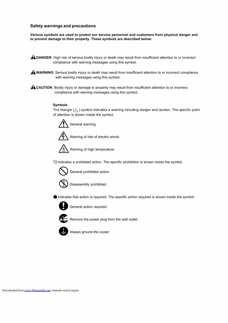
Safety warnings and precautions
Various symbols are used to protect our service personnel and customers from physical danger and
to prevent damage to their property. These symbols are described below:
DANGER: High risk of serious bodily injury or death may result from insufficient attention to or incorrect
compliance with warning messages using this symbol.
WARNING: Serious bodily injury or death may result from insufficient attention to or incorrect compliance
with warning messages using this symbol.
CAUTION: Bodily injury or damage to property may result from insufficient attention to or incorrect
compliance with warning messages using this symbol.
Symbols
The triangle ( ) symbol indicates a warning including danger and caution. The specific point
of attention is shown inside the symbol.
General warning.
Warning of risk of electric shock.
Warning of high temperature.
indicates a prohibited action. The specific prohibition is shown inside the symbol.
General prohibited action.
Disassembly prohibited.
indicates that action is required. The specific action required is shown inside the symbol.
General action required.
Remove the power plug from the wall outlet.
Always ground the copier.
loaded from www.Manualslib.com manuals search engine
8/18/2019 taskalfa_220
http://slidepdf.com/reader/full/taskalfa220 7/300
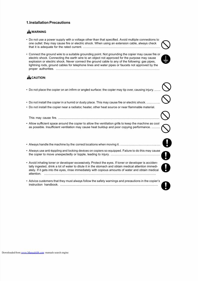
1.Installation Precautions
WARNING
• Do not use a power supply with a voltage other than that specified. Avoid multiple connections to
one outlet: they may cause fire or electric shock. When using an extension cable, always check
that it is adequate for the rated current. .............................................................................................
• Connect the ground wire to a suitable grounding point. Not grounding the copier may cause fire or
electric shock. Connecting the earth wire to an object not approved for the purpose may cause
explosion or electric shock. Never connect the ground cable to any of the following: gas pipes,
lightning rods, ground cables for telephone lines and water pipes or faucets not approved by the
proper authorities. ............................................................................................................................
CAUTION:
• Do not place the copier on an infirm or angled surface: the copier may tip over, causing injury. .......
• Do not install the copier in a humid or dusty place. This may cause fire or electric shock. ................
• Do not install the copier near a radiator, heater, other heat source or near flammable material.
This may cause fire. .........................................................................................................................
• Allow sufficient space around the copier to allow the ventilation grills to keep the machine as cool
as possible. Insufficient ventilation may cause heat buildup and poor copying performance. ...........
• Always handle the machine by the correct locations when moving it. ...............................................
• Always use anti-toppling and locking devices on copiers so equipped. Failure to do this may cause
the copier to move unexpectedly or topple, leading to injury. ...........................................................
• Avoid inhaling toner or developer excessively. Protect the eyes. If toner or developer is acciden-
tally ingested, drink a lot of water to dilute it in the stomach and obtain medical attention immedi-
ately. If it gets into the eyes, rinse immediately with copious amounts of water and obtain medical
attention. ......................................................................................................................................
• Advice customers that they must always follow the safety warnings and precautions in the copier’s
instruction handbook. .....................................................................................................................
loaded from www.Manualslib.com manuals search engine
8/18/2019 taskalfa_220
http://slidepdf.com/reader/full/taskalfa220 8/300
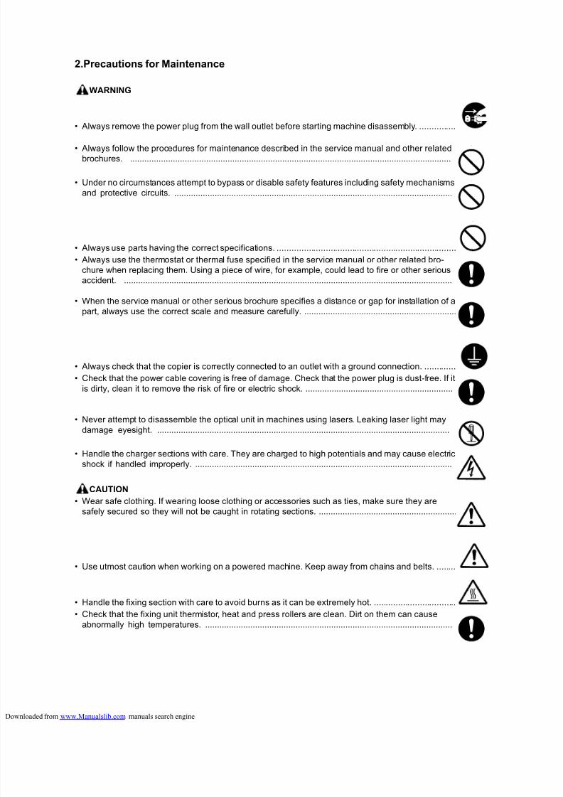
2.Precautions for Maintenance
WARNING
• Always remove the power plug from the wall outlet before starting machine disassembly. ...............
• Always follow the procedures for maintenance described in the service manual and other related
brochures. .......................................................................................................................................
• Under no circumstances attempt to bypass or disable safety features including safety mechanisms
and protective circuits. .....................................................................................................................
• Always use parts having the correct specifications. ..........................................................................
• Always use the thermostat or thermal fuse specified in the service manual or other related bro-
chure when replacing them. Using a piece of wire, for example, could lead to fire or other serious
accident. ..........................................................................................................................................
• When the service manual or other serious brochure specifies a distance or gap for installation of a
part, always use the correct scale and measure carefully. ................................................................
• Always check that the copier is correctly connected to an outlet with a ground connection. .............
• Check that the power cable covering is free of damage. Check that the power plug is dust-free. If it
is dirty, clean it to remove the risk of fire or electric shock. ..............................................................
• Never attempt to disassemble the optical unit in machines using lasers. Leaking laser light maydamage eyesight. ...........................................................................................................................
• Handle the charger sections with care. They are charged to high potentials and may cause electric
shock if handled improperly. ............................................................................................................
CAUTION
• Wear safe clothing. If wearing loose clothing or accessories such as ties, make sure they are
safely secured so they will not be caught in rotating sections. ..........................................................
• Use utmost caution when working on a powered machine. Keep away from chains and belts. ........
• Handle the fixing section with care to avoid burns as it can be extremely hot. ..................................
• Check that the fixing unit thermistor, heat and press rollers are clean. Dirt on them can cause
abnormally high temperatures. ........................................................................................................
loaded from www.Manualslib.com manuals search engine
8/18/2019 taskalfa_220
http://slidepdf.com/reader/full/taskalfa220 9/300
• Do not remove the ozone filter, if any, from the copier except for routine replacement. ....................
• Do not pull on the AC power cord or connector wires on high-voltage components when removing
them; always hold the plug itself. .....................................................................................................
• Do not route the power cable where it may be stood on or trapped. If necessary, protect it with a
cable cover or other appropriate item. .............................................................................................
• Treat the ends of the wire carefully when installing a new charger wire to avoid electric leaks. ........
• Remove toner completely from electronic components. ...................................................................
• Run wire harnesses carefully so that wires will not be trapped or damaged. ....................................
• After maintenance, always check that all the parts, screws, connectors and wires that were
removed, have been refitted correctly. Special attention should be paid to any forgotten connector,
trapped wire and missing screws. ...................................................................................................
• Check that all the caution labels that should be present on the machine according to the instruction
handbook are clean and not peeling. Replace with new ones if necessary. ......................................
• Handle greases and solvents with care by following the instructions below: .....................................· Use only a small amount of solvent at a time, being careful not to spill. Wipe spills off completely.
· Ventilate the room well while using grease or solvents.
· Allow applied solvents to evaporate completely before refitting the covers or turning the power
switch on.
· Always wash hands afterwards.
• Never dispose of toner or toner bottles in fire. Toner may cause sparks when exposed directly to
fire in a furnace, etc. .......................................................................................................................
• Should smoke be seen coming from the copier, remove the power plug from the wall outlet imme-
diately. ............................................................................................................................................
3.Miscellaneous
WARNING
• Never attempt to heat the drum or expose it to any organic solvents such as alcohol, other than the
specified refiner; it may generate toxic gas. .....................................................................................
loaded from www.Manualslib.com manuals search engine

8/18/2019 taskalfa_220
http://slidepdf.com/reader/full/taskalfa220 10/300
This page is intentionally left blank.
loaded from www.Manualslib.com manuals search engine
8/18/2019 taskalfa_220
http://slidepdf.com/reader/full/taskalfa220 11/300
2KL/2KK
CONTENTS
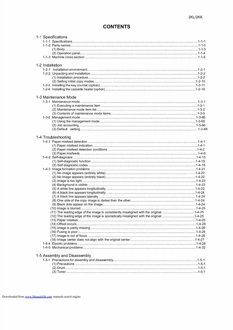
1-1 Specifications1-1-1 Specifications..........................................................................................................................................1-1-1
1-1-2 Parts names............................................................................................................................................1-1-3
(1) Body..................................................................................................................................................1-1-3
(2) Operation panel....... .................. .................. ................. ................... ................. ...................... ...........1-1-4
1-1-3 Machine cross section ............................................................................................................................1-1-5
1-2 Installation1-2-1 Installation environment.........................................................................................................................1-2-1
1-2-2 Unpacking and installation......................................................................................................................1-2-2
(1) Installation procedure................. ................... ................. .................. .................. .......................... .....1-2-2
(2) Setting initial copy modes..................... .................... ................. ................. ................. ....................1-2-10
1-2-3 Installing the key counter (option) .........................................................................................................1-2-11
1-2-4 Installing the cassette heater (option) ...................................................................................................1-2-16
1-3 Maintenance Mode1-3-1 Maintenance mode .................................................................................................................................1-3-1
(1) Executing a maintenance item ................ ................. ................. ................. ................. .................... ..1-3-1
(2) Maintenance mode item list................ .................. .................. ................. ................. ................... ......1-3-2
(3) Contents of maintenance mode items...... ...................... ................. ................. ................. ................1-3-5
1-3-2 Management mode...............................................................................................................................1-3-65
(1) Using the management mode ................ .................. .................. .................. ................. ..................1-3-65
(2) Job accounting ................ .................. .................. ................. .................. .................. .......................1-3-66
(3) Default setting .................................................................................................................................1-3-66
1-4 Troubleshooting1-4-1 Paper misfeed detection .........................................................................................................................1-4-1
(1) Paper misfeed indication............... ................... ................. .................. .................. ....................... .....1-4-1
(2) Paper misfeed detection conditions .................... ................. ................. ................. ................. ..........1-4-2
(3) Paper misfeeds .................................................................................................................................1-4-8
1-4-2 Self-diagnosis .......................................................................................................................................1-4-15
(1) Self-diagnostic function .................. ................. ................... ................. ................. ................... ........1-4-15
(2) Self diagnostic codes ......................................................................................................................1-4-16
1-4-3 Image formation problems ....................................................................................................................1-4-21
(1) No image appears (entirely white)............... ................... ................... .................. ................... .........1-4-22(2) No image appears (entirely black)................. .................. ................... .................. .................. .........1-4-22
(3) Image is too light. .................. .................. .................. ................. .................. ........................ ...........1-4-23
(4) Background is visible............... ................... ................. ................... ................ ................... ..............1-4-23
(5) A white line appears longitudinally. .................. ................. ................. ................... ................. .........1-4-23
(6) A black line appears longitudinally. .................. ................. ................. ................... ................. .........1-4-24
(7) A black line appears laterally................... .................. ................. .................. ................. ..................1-4-24
(8) One side of the copy image is darker than the other.................. ................... ................... ...............1-4-24
(9) Black dots appear on the image....... ................... ................... .................. ................... ....................1-4-24
(10) Image is blurred.................... ................. ................... ................. ................... ..................... ..............1-4-25
(11) The leading edge of the image is consistently misaligned with the original. .................. .................1-4-25
(12) The leading edge of the image is sporadically misaligned with the original................... .................1-4-25
(13) Paper creases. ................. .................. ................. .................. .................. ................. .......................1-4-25
(14) Offset occurs. ..................................................................................................................................1-4-26
(15) Image is partly missing...... ................. ................... .................. ................... .................. ...................1-4-26
(16) Fusing is poor........ .................. ................. ................. ................. ................... ....................... ...........1-4-26(17) Image is out of focus. ................. ................... ................. ................... .................. ........................ ....1-4-26
(18) Image center does not align with the original center. ................ ................. ................. ................. ...1-4-27
1-4-4 Electric problems ..................................................................................................................................1-4-28
1-4-5 Mechanical problems............................................................................................................................1-4-32
1-5 Assembly and Disassembly1-5-1 Precautions for assembly and disassembly............................................................................................1-5-1
(1) Precautions .......................................................................................................................................1-5-1
(2) Drum................ .................. ................. ................. ................. ................. ................. ...................... .....1-5-1
(3) Toner................. ................. ................. ................... ................. .................. .................. ................. .....1-5-1
loaded from www.Manualslib.com manuals search engine
8/18/2019 taskalfa_220
http://slidepdf.com/reader/full/taskalfa220 12/300
2KL/2KK-2
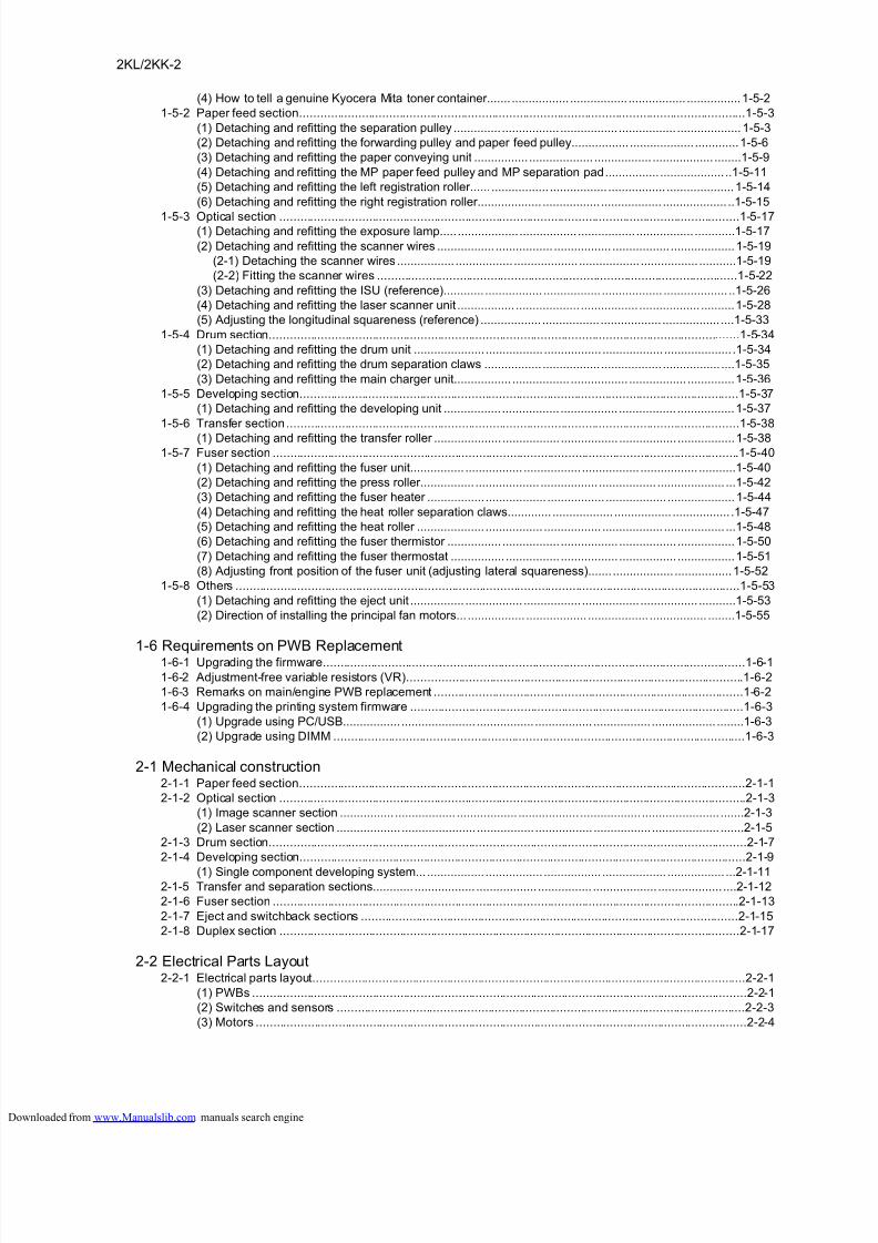
(4) How to tell a genuine Kyocera Mita toner container....... ................. ................. ................. ................1-5-2
1-5-2 Paper feed section..................................................................................................................................1-5-3
(1) Detaching and refitting the separation pulley .............. ................. ................. ................. ...................1-5-3
(2) Detaching and refitting the forwarding pulley and paper feed pulley................. ................... .............1-5-6
(3) Detaching and refitting the paper conveying unit ................ ................... ................. .................. ........1-5-9
(4) Detaching and refitting the MP paper feed pulley and MP separation pad................ ................... ..1-5-11
(5) Detaching and refitting the left registration roller...... ................. ................. ................. ....................1-5-14
(6) Detaching and refitting the right registration roller................... ................. .................. ................... ..1-5-15
1-5-3 Optical section ......................................................................................................................................1-5-17(1) Detaching and refitting the exposure lamp..... .................. ................. ................. ................. ............1-5-17
(2) Detaching and refitting the scanner wires ................. ................. ................. ................. ...................1-5-19
(2-1) Detaching the scanner wires ................. ................. ................... .................. ................. ...........1-5-19
(2-2) Fitting the scanner wires .........................................................................................................1-5-22
(3) Detaching and refitting the ISU (reference)............ ................. ................. .................. ................... ..1-5-26
(4) Detaching and refitting the laser scanner unit ................. ................... ................. .................. ..........1-5-28
(5) Adjusting the longitudinal squareness (reference) .................. ................. .................. ................. ....1-5-33
1-5-4 Drum section.........................................................................................................................................1-5-34
(1) Detaching and refitting the drum unit ..................... ................. ................. .................. .................... .1-5-34
(2) Detaching and refitting the drum separation claws ................. ................. .................. ................. ....1-5-35
(3) Detaching and refitting the main charger unit................. ................. ................. ................. ..............1-5-36
1-5-5 Developing section................................................................................................................................1-5-37
(1) Detaching and refitting the developing unit ................. ................. ................. ................. .................1-5-37
1-5-6 Transfer section....................................................................................................................................1-5-38
(1) Detaching and refitting the transfer roller .................... ................. ................. ................. .................1-5-381-5-7 Fuser section ........................................................................................................................................1-5-40
(1) Detaching and refitting the fuser unit................ ................. ................. ................. ................. ...........1-5-40
(2) Detaching and refitting the press roller................ ................... ................. ................. .................... ...1-5-42
(3) Detaching and refitting the fuser heater ................. .................. ................. .................. ....................1-5-44
(4) Detaching and refitting the heat roller separation claws............. .................. ................. ................. .1-5-47
(5) Detaching and refitting the heat roller .................... ................. ................. .................. .................. ...1-5-48
(6) Detaching and refitting the fuser thermistor ................ ................. ................. ................. .................1-5-50
(7) Detaching and refitting the fuser thermostat ................ ................ ................. ................. .................1-5-51
(8) Adjusting front position of the fuser unit (adjusting lateral squareness)....... .................. .................1-5-52
1-5-8 Others ...................................................................................................................................................1-5-53
(1) Detaching and refitting the eject unit ................ ................. ................. ................. ................. ...........1-5-53
(2) Direction of installing the principal fan motors... ................. .................. .................. ................. ........1-5-55
1-6 Requirements on PWB Replacement1-6-1 Upgrading the firmware...........................................................................................................................1-6-1
1-6-2 Adjustment-free variable resistors (VR)..................................................................................................1-6-2
1-6-3 Remarks on main/engine PWB replacement ..........................................................................................1-6-2
1-6-4 Upgrading the printing system firmware .................................................................................................1-6-3
(1) Upgrade using PC/USB................. ...................... ................. ................. ................. ................... ........1-6-3
(2) Upgrade using DIMM ........................................................................................................................1-6-3
2-1 Mechanical construction2-1-1 Paper feed section..................................................................................................................................2-1-1
2-1-2 Optical section ........................................................................................................................................2-1-3
(1) Image scanner section ................ .................. .................. .................. .................. ....................... .......2-1-3
(2) Laser scanner section ................... ...................... ................. ................. ................. .................... .......2-1-5
2-1-3 Drum section...........................................................................................................................................2-1-7
2-1-4 Developing section..................................................................................................................................2-1-9
(1) Single component developing system.................... ................. ................. ................... ................. ...2-1-112-1-5 Transfer and separation sections............ .................. .................. ................ ................... ................... ....2-1-12
2-1-6 Fuser section ........................................................................................................................................2-1-13
2-1-7 Eject and switchback sections ..............................................................................................................2-1-15
2-1-8 Duplex section ......................................................................................................................................2-1-17
2-2 Electrical Parts Layout2-2-1 Electrical parts layout..............................................................................................................................2-2-1
(1) PWBs ................................................................................................................................................2-2-1
(2) Switches and sensors .......................................................................................................................2-2-3
(3) Motors ...............................................................................................................................................2-2-4
loaded from www.Manualslib.com manuals search engine
8/18/2019 taskalfa_220
http://slidepdf.com/reader/full/taskalfa220 13/300
2KL/2KK-2
(4) Others................ ................. .................. ................. ................. ................. ....................... ................. ..2-2-5
2-3 Operation of the PWBs2-3-1 Power source PWB.................................................................................................................................2-3-1
2-3-2 Main/engine PWB ...................................................................................................................................2-3-3
2-3-3 Cassette PWB.......................................................................................................................................2-3-11
2-3-4 Operation PWB.....................................................................................................................................2-3-14
2-4 AppendixesMaintenance parts list ................ ................... .................. ................. ................... ........................ ............2-4-1
Periodic maintenance procedures .................. ................... ................... ................... .................. .............2-4-2
Chart of image adjustment procedures...................................................................................................2-4-5
Wiring diagram........................................................................................................................................2-4-7
INSTALLATION GUIDEDOCUMENT PROCESSOR
PAPER FEEDER
DUPLEX UNIT
Printing System (Z)
loaded from www.Manualslib.com manuals search engine

8/18/2019 taskalfa_220
http://slidepdf.com/reader/full/taskalfa220 14/300
2KL/2KK
This page is intentionally left blank.
loaded from www.Manualslib.com manuals search engine
8/18/2019 taskalfa_220
http://slidepdf.com/reader/full/taskalfa220 15/300
2KL/2KK
1-1-1
1-1 Specifications
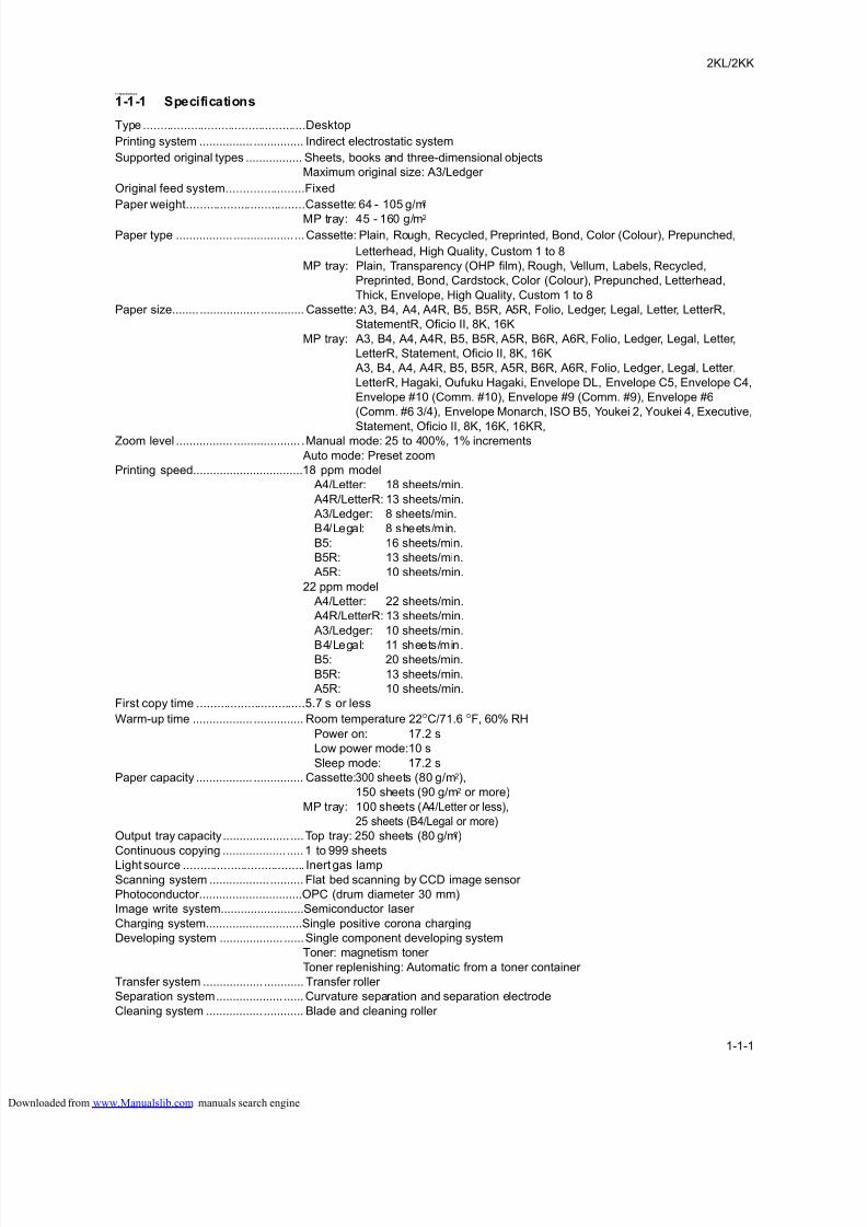
1-1-1 Specifications
Type ................................................Desktop
Printing system ................ ............... Indirect electrostatic system
Supported original types ................. Sheets, books and three-dimensional objects
Maximum original size: A3/Ledger
Original feed system.......................Fixed
Paper weight...................................Cassette: 64 - 105 g/m2
MP tray: 45 - 160 g/m2
Paper type ................. .................. ...Cassette: Plain, Rough, Recycled, Preprinted, Bond, Color (Colour), Prepunched,
Letterhead, High Quality, Custom 1 to 8
MP tray: Plain, Transparency (OHP film), Rough, Vellum, Labels, Recycled,
Preprinted, Bond, Cardstock, Color (Colour), Prepunched, Letterhead,
Thick, Envelope, High Quality, Custom 1 to 8
Paper size........ .................. ............. Cassette: A3, B4, A4, A4R, B5, B5R, A5R, Folio, Ledger, Legal, Letter, LetterR,
StatementR, Oficio II, 8K, 16K
MP tray: A3, B4, A4, A4R, B5, B5R, A5R, B6R, A6R, Folio, Ledger, Legal, Letter,
LetterR, Statement, Oficio II, 8K, 16K
A3, B4, A4, A4R, B5, B5R, A5R, B6R, A6R, Folio, Ledger, Legal, Letter,
LetterR, Hagaki, Oufuku Hagaki, Envelope DL, Envelope C5, Envelope C4,
Envelope #10 (Comm. #10), Envelope #9 (Comm. #9), Envelope #6
(Comm. #6 3/4), Envelope Monarch, ISO B5, Youkei 2, Youkei 4, Executive,
Statement, Oficio II, 8K, 16K, 16KR,Zoom level ................. .................... .Manual mode: 25 to 400%, 1% increments
Auto mode: Preset zoom
Printing speed.................................18 ppm model
A4/Letter: 18 sheets/min.
A4R/LetterR: 13 sheets/min.
A3/Ledger: 8 sheets/min.
B4/Legal: 8 sheets/min.
B5: 16 sheets/min.
B5R: 13 sheets/min.
A5R: 10 sheets/min.
22 ppm model
A4/Letter: 22 sheets/min.
A4R/LetterR: 13 sheets/min.
A3/Ledger: 10 sheets/min.
B4/Legal: 11 sheets/min.B5: 20 sheets/min.
B5R: 13 sheets/min.
A5R: 10 sheets/min.
First copy time ................................5.7 s or less
Warm-up time .................. ............... Room temperature 22 °C/71.6 °F, 60% RH
Power on: 17.2 s
Low power mode:10 s
Sleep mode: 17.2 s
Paper capacity ................. ............... Cassette: 300 sheets (80 g/m2),
150 sheets (90 g/m2 or more)
MP tray: 100 sheets (A4/Letter or less),
25 sheets (B4/Legal or more)
Output tray capacity.................... ....Top tray: 250 sheets (80 g/m2)
Continuous copying ................... .....1 to 999 sheets
Light source .................................... Inert gas lamp
Scanning system .................. .......... Flat bed scanning by CCD image sensor
Photoconductor...............................OPC (drum diameter 30 mm)
Image write system.........................Semiconductor laser
Charging system.............................Single positive corona charging
Developing system ................... ......Single component developing system
Toner: magnetism toner
Toner replenishing: Automatic from a toner container
Transfer system .................. ............ Transfer roller
Separation system.................... ......Curvature separation and separation electrode
Cleaning system ................. ............ Blade and cleaning roller
loaded from www.Manualslib.com manuals search engine
8/18/2019 taskalfa_220
http://slidepdf.com/reader/full/taskalfa220 16/300
2KL/2KK
1-1-2
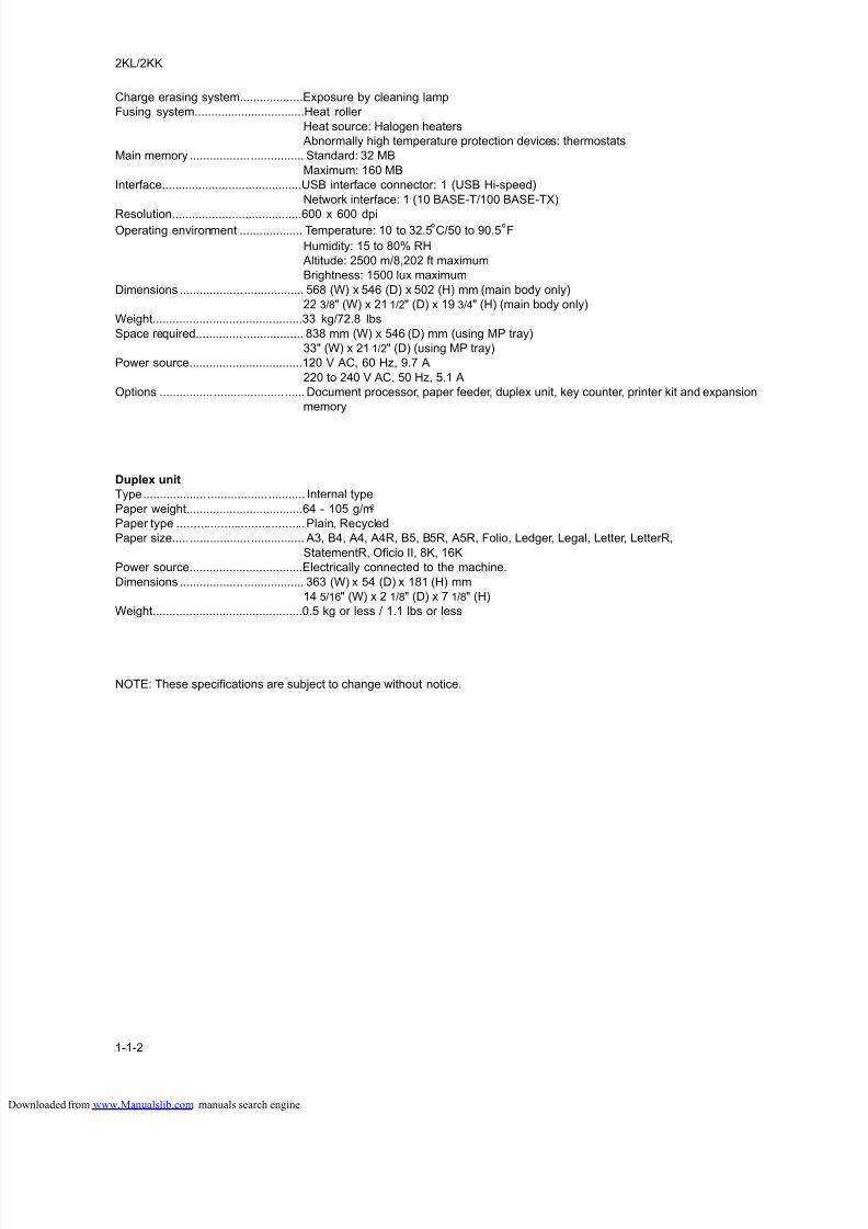
Charge erasing system...................Exposure by cleaning lamp
Fusing system.................................Heat roller
Heat source: Halogen heaters
Abnormally high temperature protection devices: thermostats
Main memory .................. ................ Standard: 32 MB
Maximum: 160 MB
Interface..........................................USB interface connector: 1 (USB Hi-speed)
Network interface: 1 (10 BASE-T/100 BASE-TX)
Resolution.......................................600 x 600 dpiOperating environment ................... Temperature: 10 to 32.5°C/50 to 90.5°F
Humidity: 15 to 80% RH
Altitude: 2500 m/8,202 ft maximum
Brightness: 1500 lux maximum
Dimensions ................... .................. 568 (W) x 546 (D) x 502 (H) mm (main body only)
22 3/8" (W) x 21 1/2" (D) x 19 3/4" (H) (main body only)
Weight.............................................33 kg/72.8 lbs
Space required.............. .................. 838 mm (W) x 546 (D) mm (using MP tray)
33" (W) x 21 1/2" (D) (using MP tray)
Power source..................................120 V AC, 60 Hz, 9.7 A
220 to 240 V AC, 50 Hz, 5.1 A
Options ................ ..................... ......Document processor, paper feeder, duplex unit, key counter, printer kit and expansion
memory
Duplex unit
Type................... .................. ........... Internal type
Paper weight...................................64 - 105 g/m2
Paper type ......................................Plain, Recycled
Paper size..... .................. ................ A3, B4, A4, A4R, B5, B5R, A5R, Folio, Ledger, Legal, Letter, LetterR,
StatementR, Oficio II, 8K, 16K
Power source..................................Electrically connected to the machine.
Dimensions ................... .................. 363 (W) x 54 (D) x 181 (H) mm
14 5/16" (W) x 2 1/8" (D) x 7 1/8" (H)
Weight.............................................0.5 kg or less / 1.1 lbs or less
NOTE: These specifications are subject to change without notice.
loaded from www.Manualslib.com manuals search engine
8/18/2019 taskalfa_220
http://slidepdf.com/reader/full/taskalfa220 17/300
2KL/2KK
1-1-3
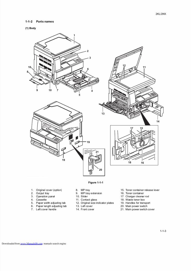
1-1-2 Parts names
(1) Body
Figure 1-1-1
1
1112
10
8
7 4
5
6
2
3
10
19
19
20
21
18
14
13
1517
16
9
1. Original cover (option)2. Output tray
3. Operation panel
4. Cassette
5. Paper width adjusting tab
6. Paper length adjusting tab
7. Left cover handle
8. MP tray9. MP tray extension
10. Slider
11. Contact glass
12. Original size indicator plates
13. Left cover
14. Front cover
15. Toner container release lever 16. Toner container
17. Charger cleaner rod
18. Waste toner box
19. Handles for transport
20. Main power switch
21. Main power switch cover
loaded from www.Manualslib.com manuals search engine
8/18/2019 taskalfa_220
http://slidepdf.com/reader/full/taskalfa220 18/300
2KL/2KK
1-1-4
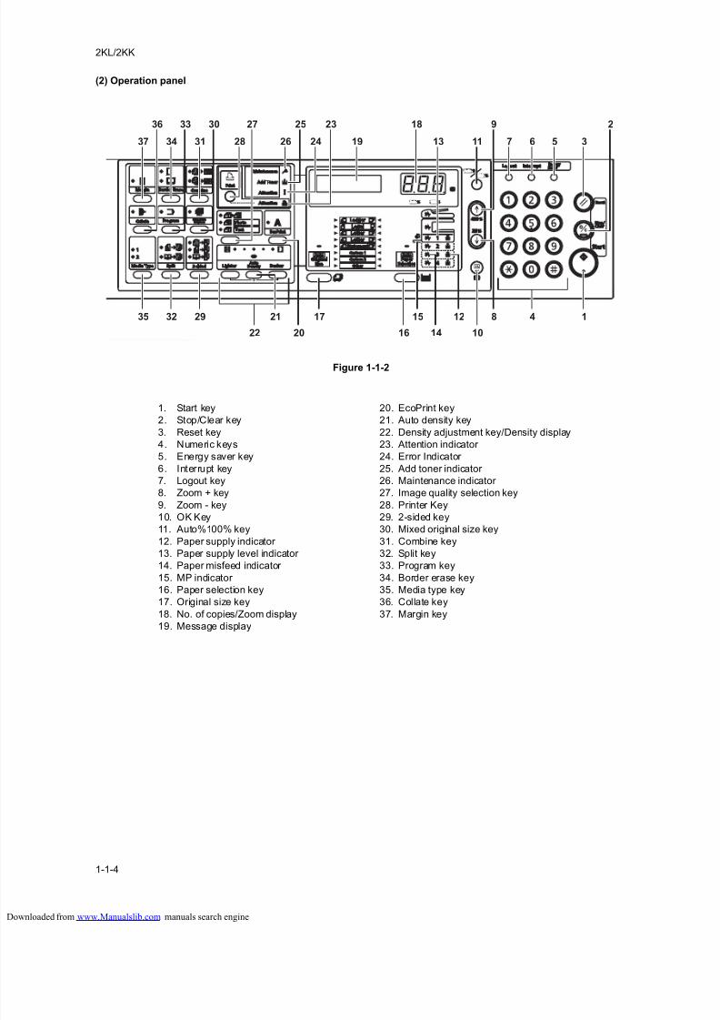
(2) Operation panel
Figure 1-1-2
37 34 31
35 32 29 21
22 16 1014
17 4 115 12
26 19 13 11 7 6 5 324
36 33 30 25 23
28
27 18 9 2
8
20
1. Start key
2. Stop/Clear key
3. Reset key
4. Numeric keys
5. Energy saver key
6. Interrupt key
7. Logout key
8. Zoom + key
9. Zoom - key
10. OK Key
11. Auto%100% key
12. Paper supply indicator
13. Paper supply level indicator
14. Paper misfeed indicator
15. MP indicator
16. Paper selection key
17. Original size key
18. No. of copies/Zoom display
19. Message display
20. EcoPrint key
21. Auto density key
22. Density adjustment key/Density display
23. Attention indicator
24. Error Indicator
25. Add toner indicator
26. Maintenance indicator
27. Image quality selection key
28. Printer Key
29. 2-sided key
30. Mixed original size key
31. Combine key
32. Split key
33. Program key
34. Border erase key
35. Media type key
36. Collate key
37. Margin key
loaded from www.Manualslib.com manuals search engine
8/18/2019 taskalfa_220
http://slidepdf.com/reader/full/taskalfa220 19/300
2KL/2KK
1-1-5
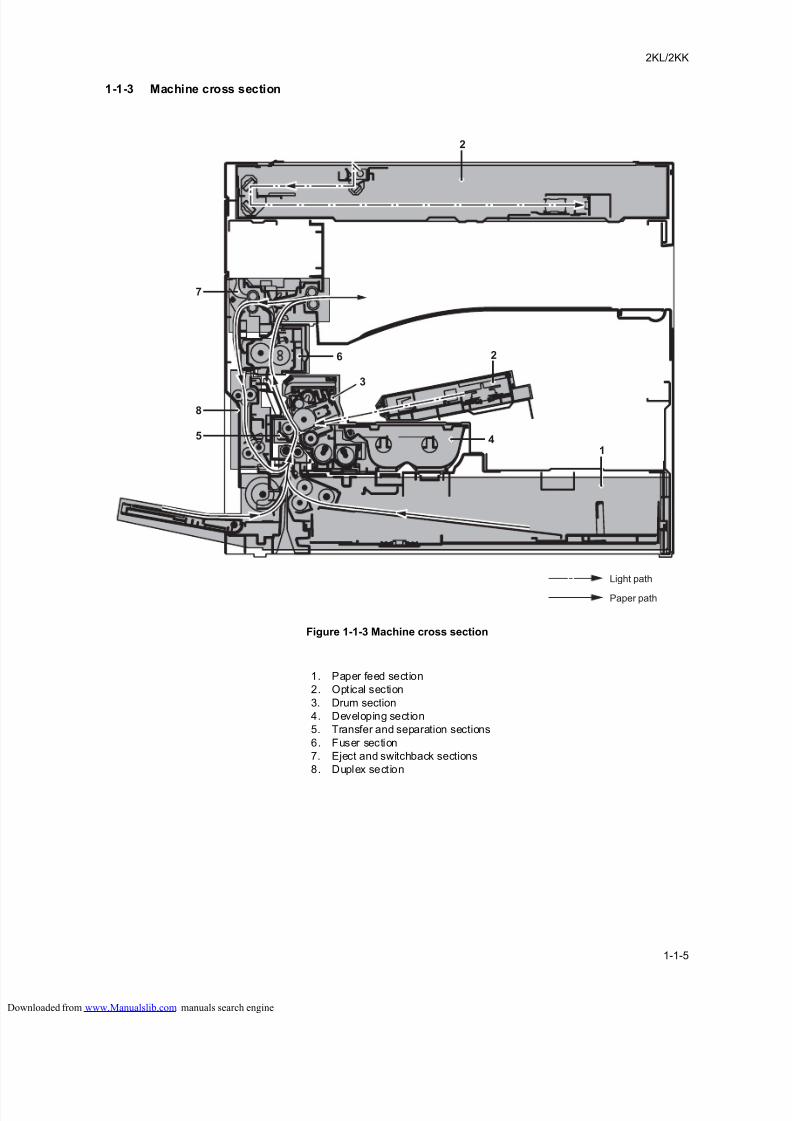
1-1-3 Machine cross section
Figure 1-1-3 Machine cross section
2
2
1
7
6
3
4
8
5
Paper path
Light path
1. Paper feed section
2. Optical section
3. Drum section
4. Developing section
5. Transfer and separation sections
6. Fuser section
7. Eject and switchback sections
8. Duplex section
loaded from www.Manualslib.com manuals search engine

8/18/2019 taskalfa_220
http://slidepdf.com/reader/full/taskalfa220 20/300
2KL/2KK
1-1-6
This page is intentionally left blank.
loaded from www.Manualslib.com manuals search engine
8/18/2019 taskalfa_220
http://slidepdf.com/reader/full/taskalfa220 21/300
2KL/2KK
1-2-1
1-2 Installation
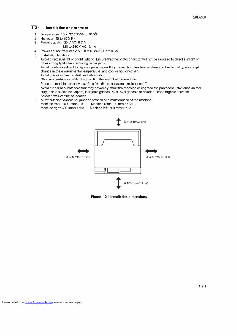
1-2-1 Installation environment
1. Temperature: 10 to 32.5°C/50 to 90.5°F
2. Humidity: 15 to 80% RH
3. Power supply: 120 V AC, 9.7 A
220 to 240 V AC, 5.1 A
4. Power source frequency: 50 Hz ± 0.3%/60 Hz ± 0.3%
5. Installation location
Avoid direct sunlight or bright lighting. Ensure that the photoconductor will not be exposed to direct sunlight orother strong light when removing paper jams.
Avoid locations subject to high temperature and high humidity or low temperature and low humidity; an abrupt
change in the environmental temperature; and cool or hot, direct air.
Avoid places subject to dust and vibrations.
Choose a surface capable of supporting the weight of the machine.
Place the machine on a level surface (maximum allowance inclination: 1°).
Avoid air-borne substances that may adversely affect the machine or degrade the photoconductor, such as mer-
cury, acidic of alkaline vapors, inorganic gasses, NOx, SOx gases and chlorine-based organic solvents.
Select a well-ventilated location.
6. Allow sufficient access for proper operation and maintenance of the machine.
Machine front: 1000 mm/39 3/8" Machine rear: 100 mm/3 15/16"
Machine right: 300 mm/11 13/16" Machine left: 300 mm/1113/16
Figure 1-2-1 Installation dimensions
300 mm/11 13/16"300 mm/11 13/16"
1000 mm/39 3/8"
100 mm/3 15/16"
loaded from www.Manualslib.com manuals search engine
8/18/2019 taskalfa_220
http://slidepdf.com/reader/full/taskalfa220 22/300
2KL/2KK
1-2-2
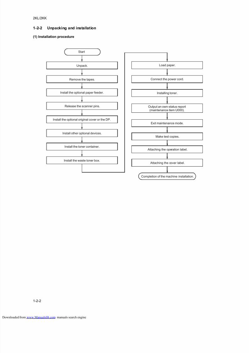
1-2-2 Unpacking and installation
(1) Installation procedure
Unpack.
Remove the tapes.
Install the optional paper feeder.
Release the scanner pins.
Install the toner container.
Connect the power cord.
Load paper.
Installing toner.
Make test copies.
Attaching the operation label.
Attaching the cover label.
Output an own-status report(maintenance item U000).
Exit maintenance mode.
Start
Install other optional devices.
Install the waste toner box.
Install the optional original cover or the DP.
Completion of the machine installation.
loaded from www.Manualslib.com manuals search engine
8/18/2019 taskalfa_220
http://slidepdf.com/reader/full/taskalfa220 23/300
2KL/2KK
1-2-3
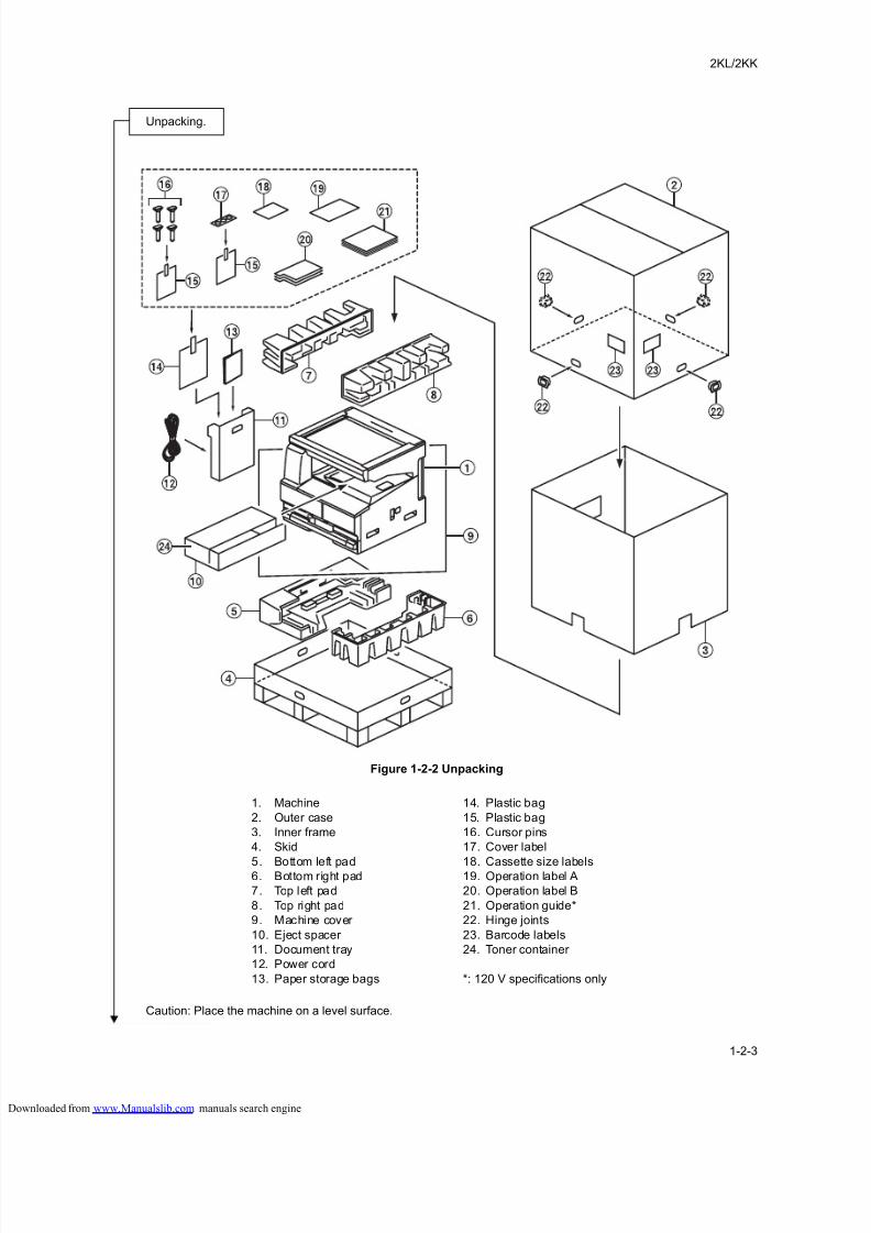
Figure 1-2-2 Unpacking
Caution: Place the machine on a level surface.
Unpacking.
1. Machine
2. Outer case
3. Inner frame
4. Skid
5. Bottom left pad6. Bottom right pad
7. Top left pad
8. Top right pad
9. Machine cover
10. Eject spacer
11. Document tray
12. Power cord
13. Paper storage bags
14. Plastic bag
15. Plastic bag
16. Cursor pins
17. Cover label
18. Cassette size labels19. Operation label A
20. Operation label B
21. Operation guide*
22. Hinge joints
23. Barcode labels
24. Toner container
*: 120 V specifications only
loaded from www.Manualslib.com manuals search engine
8/18/2019 taskalfa_220
http://slidepdf.com/reader/full/taskalfa220 24/300
2KL/2KK
1-2-4
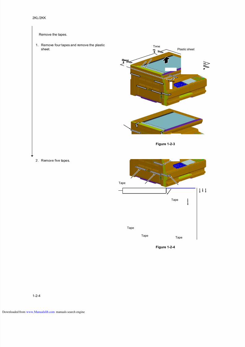
1. Remove four tapes and remove the plastic
sheet.
Figure 1-2-3
2. Remove five tapes.
Figure 1-2-4
Remove the tapes.
Tape
Tape
Tape
Plastic sheet
Tape
Tape
Tape
Tape
Tape
Tape
loaded from www.Manualslib.com manuals search engine
8/18/2019 taskalfa_220
http://slidepdf.com/reader/full/taskalfa220 25/300
2KL/2KK
1-2-5
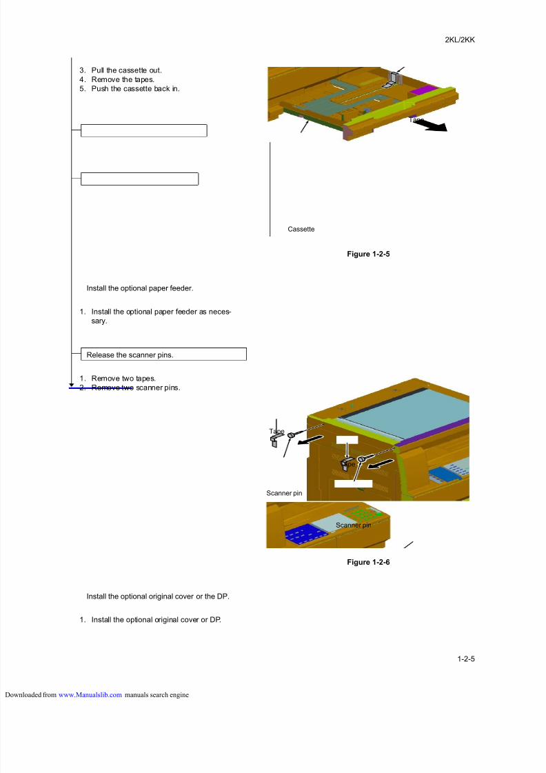
3. Pull the cassette out.
4. Remove the tapes.
5. Push the cassette back in.
Figure 1-2-5
1. Install the optional paper feeder as neces-
sary.
1. Remove two tapes.
2. Remove two scanner pins.
Figure 1-2-6
1. Install the optional original cover or DP.
Tape
Cassette
Install the optional paper feeder.
Release the scanner pins.
Tape
Scanner pin
Scanner pin
Tape
Install the optional original cover or the DP.
loaded from www.Manualslib.com manuals search engine
8/18/2019 taskalfa_220
http://slidepdf.com/reader/full/taskalfa220 26/300
2KL/2KK
1-2-6
1. Install the optional devices (duplex unit and/
or printer kit etc.) as necessary.
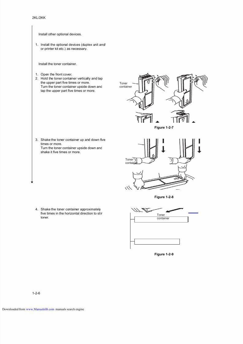
1. Open the front cover.
2. Hold the toner container vertically and tap
the upper part five times or more.
Turn the toner container upside down and
tap the upper part five times or more.
Figure 1-2-7
3. Shake the toner container up and down five
times or more.
Turn the toner container upside down and
shake it five times or more.
Figure 1-2-8
4. Shake the toner container approximately
five times in the horizontal direction to st ir
toner.
Figure 1-2-9
Install other optional devices.
Install the toner container.
Tonercontainer
Toner container
Toner container
loaded from www.Manualslib.com manuals search engine
8/18/2019 taskalfa_220
http://slidepdf.com/reader/full/taskalfa220 27/300
2KL/2KK
1-2-7
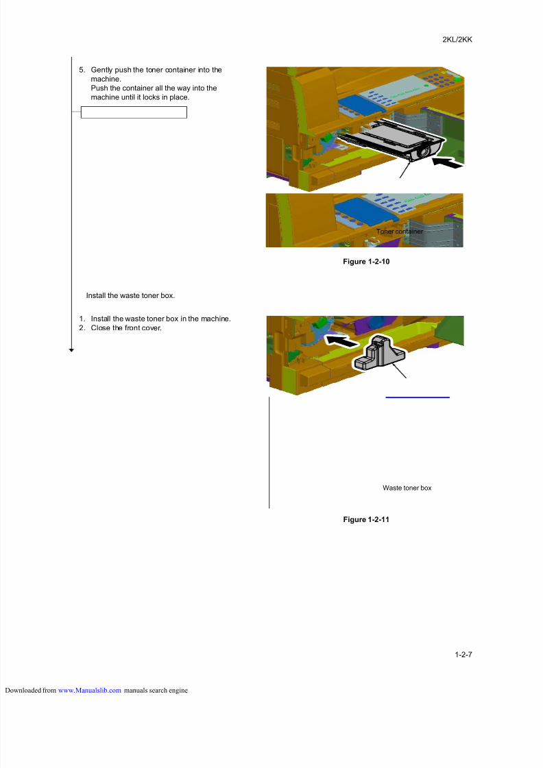
5. Gently push the toner container into the
machine.
Push the container all the way into the
machine until it locks in place.
Figure 1-2-10
1. Install the waste toner box in the machine.
2. Close the front cover.
Figure 1-2-11
Toner container
Install the waste toner box.
Waste toner box
loaded from www.Manualslib.com manuals search engine
8/18/2019 taskalfa_220
http://slidepdf.com/reader/full/taskalfa220 28/300
2KL/2KK
1-2-8
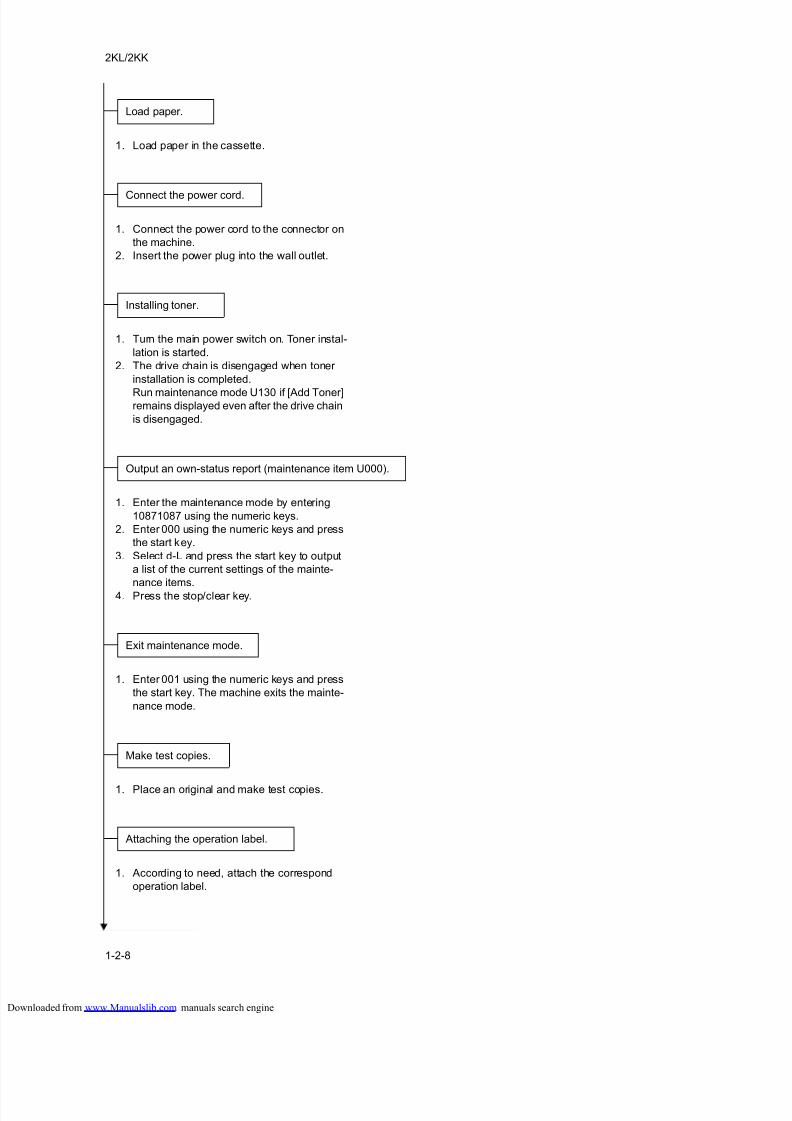
1. Load paper in the cassette.
1. Connect the power cord to the connector on
the machine.
2. Insert the power plug into the wall outlet.
1. Turn the main power switch on. Toner instal-
lation is started.
2. The drive chain is disengaged when toner
installation is completed.
Run maintenance mode U130 if [Add Toner]remains displayed even after the drive chain
is disengaged.
1. Enter the maintenance mode by entering
10871087 using the numeric keys.
2. Enter 000 using the numeric keys and press
the start key.
3. Select d-L and press the start key to output
a list of the current settings of the mainte-
nance items.
4. Press the stop/clear key.
1. Enter 001 using the numeric keys and press
the start key. The machine exits the mainte-
nance mode.
1. Place an original and make test copies.
1. According to need, attach the correspond
operation label.
Load paper.
Connect the power cord.
Installing toner.
Output an own-status report (maintenance item U000).
Exit maintenance mode.
Make test copies.
Attaching the operation label.
loaded from www.Manualslib.com manuals search engine
8/18/2019 taskalfa_220
http://slidepdf.com/reader/full/taskalfa220 29/300
2KL/2KK
1-2-9
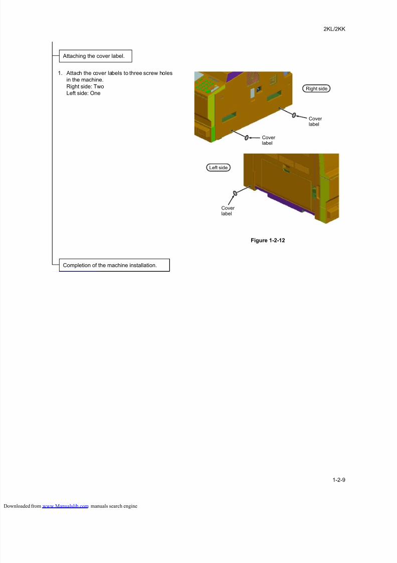
1. Attach the cover labels to three screw holes
in the machine.
Right side: Two
Left side: One
Figure 1-2-12
Attaching the cover label.
Right side
Left side
Coverlabel
Coverlabel
Coverlabel
Completion of the machine installation.
loaded from www.Manualslib.com manuals search engine
8/18/2019 taskalfa_220
http://slidepdf.com/reader/full/taskalfa220 30/300
2KL/2KK-1
1-2-10
(2) Setting initial copy modes
Factory settings are as follows:
Maintenance
item No.Contents Factory setting
U253 Switching between double and single counts DOUBLE COUNT(A3/LEDGER)
U254 Turning auto start function on/off ON
U260 Selecting the timing for copy counting After ejection
U277 Setting auto application change time 30 s
U285 Setting service status page ON
U342 Setting the ejection restriction ON
U343 Switching between duplex/simplex copy mode OFF
U344 Setting the low-power mode ENERGY STAR (inch specifications)
GEEA (metric specifications)
loaded from www.Manualslib.com manuals search engine
8/18/2019 taskalfa_220
http://slidepdf.com/reader/full/taskalfa220 31/300
2KL/2KK-1
1-2-11
1-2-3 Installing the key counter (option)
Installing the key counter requires the following component:
Key counter (P/N 3025418011)
Key counter set (P/N 302A369708)
Key counter wire set (P/N 302KK94590)
Key counter mounting plate (P/N 2C960100)
Supplied parts of key counter set:
Key counter socket assembly (P/N 3029236241)
Key counter cover (P/N 3066060011)
Key counter mount (P/N 3066060041)
Key counter retainer (P/N 302GR03020)
Key counter cover retainer (P/N 302GR03010)
Two (2) Edgings (P/N 7YZM210006++H01)
One (1) Band (P/N M21AH010)
One (1) M3 × 8 tap-tight P screw (P/N 5MBTPB3008PW++R)
Two (2) M4 × 10 tap-tight P screws (P/N 5MBTPB4010PW++R)
Two (2) M4 × 10 tap-tight S screws (P/N 5MBTPB4010TW++R)
Two (2) M3 × 6 bronze flat-head screws (P/N 7BB003306H)
One (1) M4 × 20 tap-tight S screw (P/N 7BB100420H)
One (1) M3 bronze nut (P/N 7BC1003055++H01)
One (1) M3 × 8 bronze binding screw (P/N B1B03080)
One (1) M4 × 30 tap-tight S screw (P/N B1B54300)Five (5) M4 × 6 chrome TP screws (P/N B4A04060)
Two (2) M4 × 10 chrome TP screws (P/N B4A04100)
Supplied parts of key counter wire set:
Key counter wire (P/N 302KK46300)
One (1) Wire saddle RLWC-1SV (P/N 7YZM610001++H01)
One (1) Wire saddle RLWT-0.5V (P/N 7YZM610009++H01)
One (1) Edging (P/N 7YZM210003++H01)
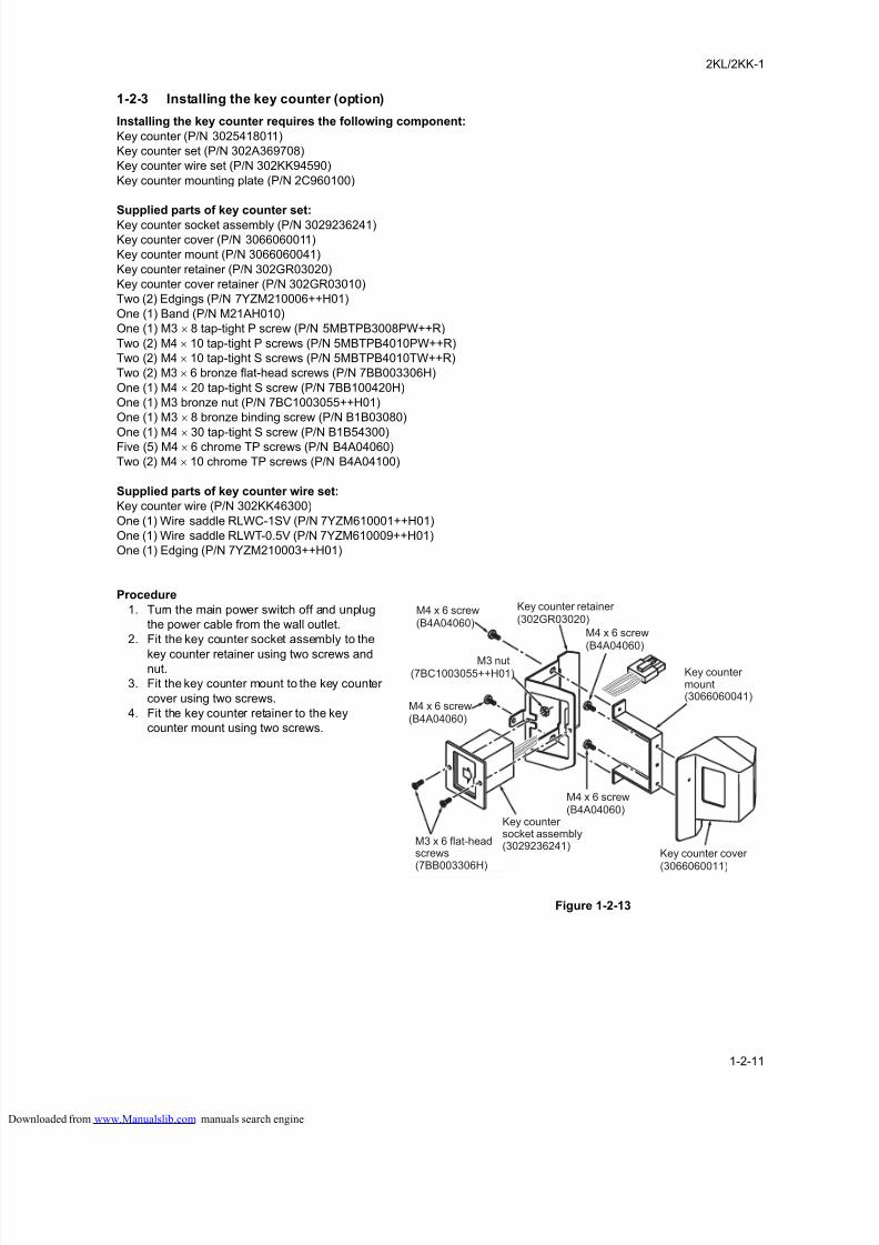
Procedure
1. Turn the main power switch off and unplug
the power cable from the wall outlet.
2. Fit the key counter socket assembly to the
key counter retainer using two screws andnut.
3. Fit the key counter mount to the key counter
cover using two screws.
4. Fit the key counter retainer to the key
counter mount using two screws.
Figure 1-2-13
M3 x 6 flat-headscrews(7BB003306H)
Key countermount(3066060041)
Key counter cover (3066060011)
M4 x 6 screw(B4A04060)
M4 x 6 screw(B4A04060)
Key countersocket assembly(3029236241)
M4 x 6 screw(B4A04060)
M3 nut(7BC1003055++H01)
Key counter retainer (302GR03020)
M4 x 6 screw(B4A04060)
loaded from www.Manualslib.com manuals search engine
8/18/2019 taskalfa_220
http://slidepdf.com/reader/full/taskalfa220 32/300
2KL/2KK
1-2-12
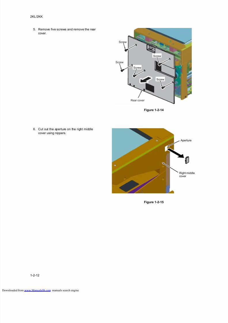
5. Remove five screws and remove the rear
cover.
Figure 1-2-14
6. Cut out the aperture on the right middle
cover using nippers.
Figure 1-2-15
Screw
Screw
Screw
Screw
Screw
Rear cover
Aperture
Right middlecover
loaded from www.Manualslib.com manuals search engine
8/18/2019 taskalfa_220
http://slidepdf.com/reader/full/taskalfa220 33/300
2KL/2KK-1
1-2-13
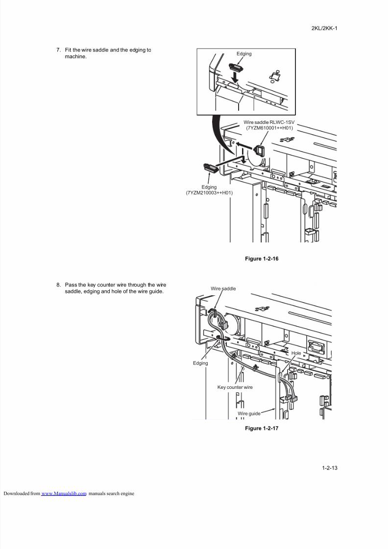
7. Fit the wire saddle and the edging to
machine.
Figure 1-2-16
8. Pass the key counter wire through the wire
saddle, edging and hole of the wire guide.
Figure 1-2-17
Edging
Wire saddle RLWC-1SV(7YZM610001++H01)
Edging
(7YZM210003++H01)
Hole
Wire guide
Wire saddle
Key counter wire
Edging
loaded from www.Manualslib.com manuals search engine
8/18/2019 taskalfa_220
http://slidepdf.com/reader/full/taskalfa220 34/300
2KL/2KK
1-2-14
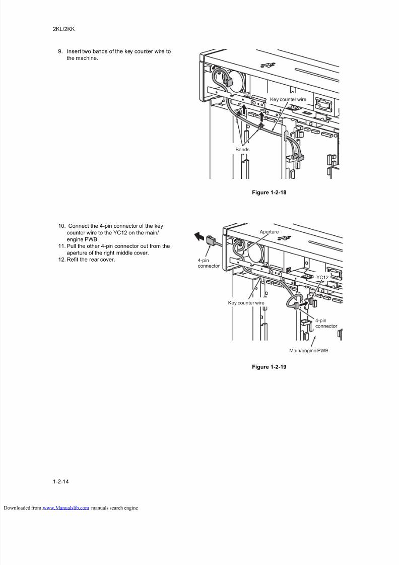
9. Insert two bands of the key counter wire to
the machine.
Figure 1-2-18
10. Connect the 4-pin connector of the key
counter wire to the YC12 on the main/
engine PWB.
11. Pull the other 4-pin connector out from the
aperture of the right middle cover.
12. Refit the rear cover.
Figure 1-2-19
Bands
Key counter wire
YC12
Aperture
4-pinconnector
4-pinconnector
Key counter wire
Main/engine PWB
loaded from www.Manualslib.com manuals search engine
8/18/2019 taskalfa_220
http://slidepdf.com/reader/full/taskalfa220 35/300
2KL/2KK
1-2-15
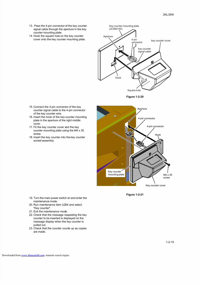
13. Pass the 4-pin connector of the key counter
signal cable through the aperture in the key
counter mounting plate.
14. Hook the square hole on the key counter
cover onto the key counter mounting plate.
Figure 1-2-20
15. Connect the 4-pin connector of the key
counter signal cable to the 4-pin connector
of the key counter wire.
16. Insert the hook of the key counter mounting
plate in the aperture of the right middle
cover.
17. Fit the key counter cover and the key
counter mounting plate using the M4 x 30
screw.
18. Insert the key counter into the key counter
socket assembly.
Figure 1-2-21
19. Turn the main power switch on and enter themaintenance mode.
20. Run maintenance item U204 and select
"Key counter".
21. Exit the maintenance mode.
22. Check that the message requesting the key
counter to be inserted is displayed on the
message display when the key counter is
pulled out.
23. Check that the counter counts up as copies
are made.
Square hole
Key counter mounting plate(2C960100)
4-pinconnector
Aperture
key counter cover
key countersignal cable
Hook
Key counter cover
Key countermounting plate M4 x 30
screw
4-pin connector
4-pin connector
Hook
Aperture
loaded from www.Manualslib.com manuals search engine
8/18/2019 taskalfa_220
http://slidepdf.com/reader/full/taskalfa220 36/300
2KL/2KK
1-2-16
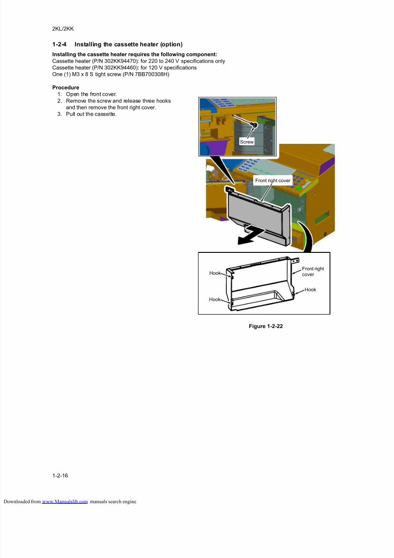
1-2-4 Installing the cassette heater (option)
Installing the cassette heater requires the following component:
Cassette heater (P/N 302KK94470): for 220 to 240 V specifications only
Cassette heater (P/N 302KK94460): for 120 V specifications
One (1) M3 x 8 S tight screw (P/N 7BB700308H)
Procedure
1. Open the front cover.
2. Remove the screw and release three hooks
and then remove the front right cover.
3. Pull out the cassette.
Figure 1-2-22
Front right cover
Screw
Front rightcover Hook
Hook
Hook
loaded from www.Manualslib.com manuals search engine
8/18/2019 taskalfa_220
http://slidepdf.com/reader/full/taskalfa220 37/300
2KL/2KK
1-2-17
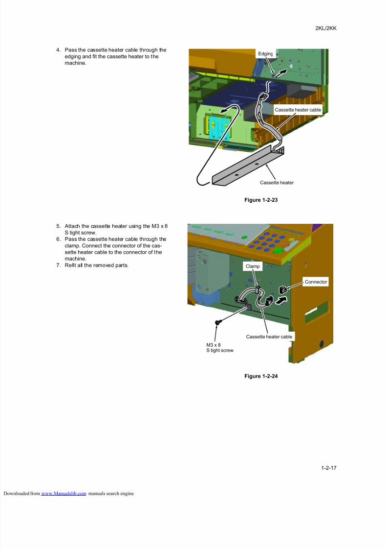
4. Pass the cassette heater cable through the
edging and fit the cassette heater to the
machine.
Figure 1-2-23
5. Attach the cassette heater using the M3 x 8
S tight screw.
6. Pass the cassette heater cable through the
clamp. Connect the connector of the cas-
sette heater cable to the connector of the
machine.
7. Refit all the removed parts.
Figure 1-2-24
Cassette heater cable
Edging
Cassette heater
Cassette heater cable
M3 x 8S tight screw
Connector
Clamp
loaded from www.Manualslib.com manuals search engine

8/18/2019 taskalfa_220
http://slidepdf.com/reader/full/taskalfa220 38/300
2KL/2KK
1-2-18
This page is intentionally left blank.
loaded from www.Manualslib.com manuals search engine
8/18/2019 taskalfa_220
http://slidepdf.com/reader/full/taskalfa220 39/300
2KL/2KK
1-3-1
1-3 Maintenance Mode
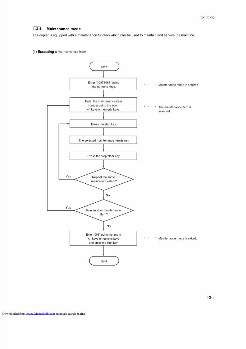
1-3-1 Maintenance mode
The copier is equipped with a maintenance function which can be used to maintain and service the machine.
(1) Executing a maintenance item
Enter “10871087” using
the numeric keys.
Enter “001” using the zoom
+/- keys or numeric keys
and press the start key.
Enter the maintenance item
number using the zoom
+/- keys or numeric keys.
The selected maintenance item is run.
Press the stop/clear key.
Press the start key.
Start
End
Maintenance mode is entered.
The maintenance item is
selected.
Maintenance mode is exited.
Repeat the same
maintenance item?
Run another maintenance
item?
No
No
Yes
Yes
loaded from www.Manualslib.com manuals search engine
8/18/2019 taskalfa_220
http://slidepdf.com/reader/full/taskalfa220 40/300
2KL/2KK-1
1-3-2
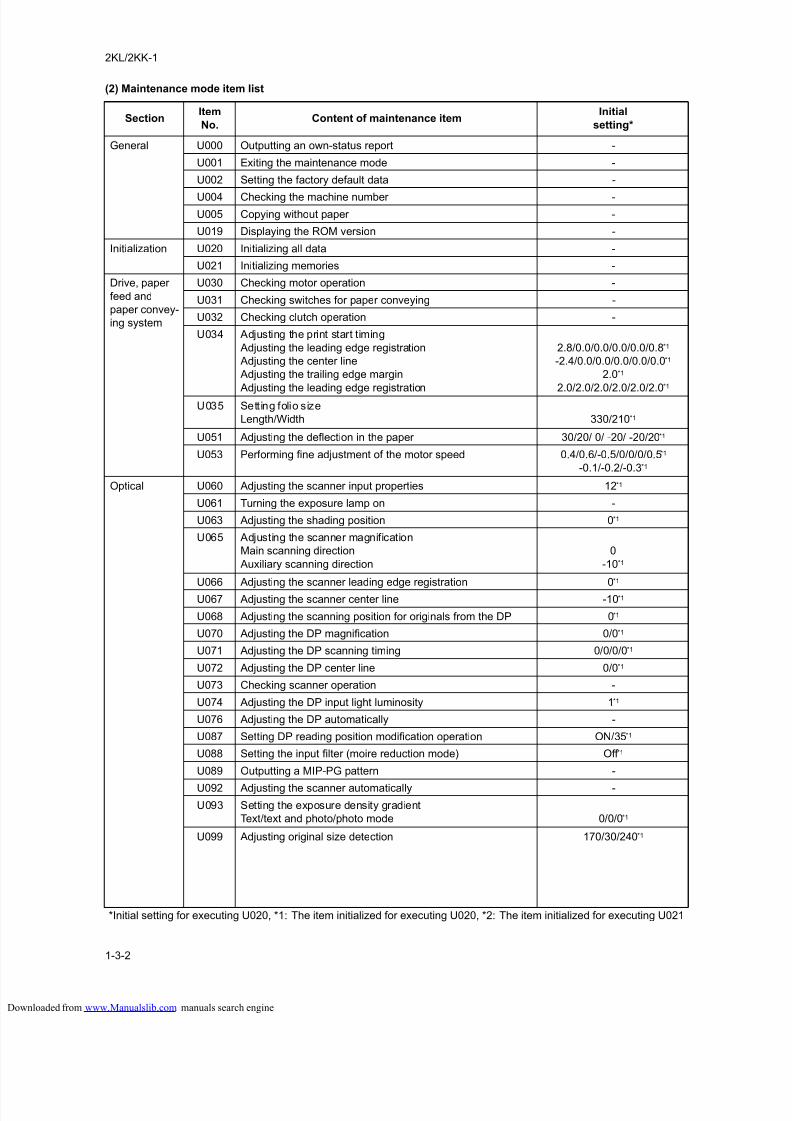
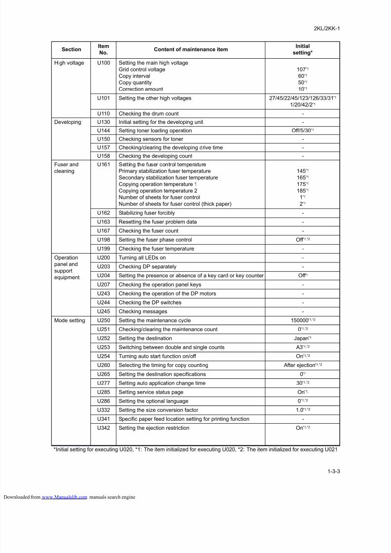
(2) Maintenance mode item list
SectionItem
No.Content of maintenance item
Initial
setting*
General U000 Outputting an own-status report -
U001 Exiting the maintenance mode -
U002 Setting the factory default data -
U004 Checking the machine number -
U005 Copying without paper -
U019 Displaying the ROM version -
Initialization U020 Initializing all data -
U021 Initializing memories -
Drive, paper
feed and
paper convey-
ing system
U030 Checking motor operation -
U031 Checking switches for paper conveying -
U032 Checking clutch operation -
U034 Adjusting the print start timing
Adjusting the leading edge registration
Adjusting the center line
Adjusting the trailing edge margin
Adjusting the leading edge registration
2.8/0.0/0.0/0.0/0.0/0.8*1
-2.4/0.0/0.0/0.0/0.0/0.0*1
2.0*1
2.0/2.0/2.0/2.0/2.0/2.0*1
U035 Setting folio size
Length/Width 330/210*1
U051 Adjusting the deflection in the paper 30/20/ 0/ -20/ -20/20*1
U053 Performing fine adjustment of the motor speed 0.4/0.6/-0.5/0/0/0/0.5*1
-0.1/-0.2/-0.3*1
Optical U060 Adjusting the scanner input properties 12*1
U061 Turning the exposure lamp on -
U063 Adjusting the shading position 0*1
U065 Adjusting the scanner magnification
Main scanning direction
Auxiliary scanning direction
0
-10*1
U066 Adjusting the scanner leading edge registration 0*1
U067 Adjusting the scanner center line -10*1
U068 Adjusting the scanning position for originals from the DP 0*1
U070 Adjusting the DP magnification 0/0*1
U071 Adjusting the DP scanning timing 0/0/0/0*1
U072 Adjusting the DP center line 0/0*1
U073 Checking scanner operation -
U074 Adjusting the DP input light luminosity 1*1
U076 Adjusting the DP automatically -
U087 Setting DP reading position modification operation ON/35*1
U088 Setting the input filter (moire reduction mode) Off *1
U089 Outputting a MIP-PG pattern -
U092 Adjusting the scanner automatically -
U093 Setting the exposure density gradient
Text/text and photo/photo mode 0/0/0*1
U099 Adjusting original size detection 170/30/240*1
*Initial setting for executing U020, *1: The item initialized for executing U020, *2: The item initialized for executing U021
loaded from www.Manualslib.com manuals search engine
8/18/2019 taskalfa_220
http://slidepdf.com/reader/full/taskalfa220 41/300
2KL/2KK-1
1-3-3
High voltage U100 Setting the main high voltage
Grid control voltage
Copy interval
Copy quantity
Correction amount
107*1
60*1
50*1
10*1
U101 Setting the other high voltages 27/45/22/45/123/126/33/31*1
1/20/42/2*1
U110 Checking the drum count -
Developing U130 Initial setting for the developing unit -
U144 Setting toner loading operation Off/5/30*1
U150 Checking sensors for toner -
U157 Checking/clearing the developing drive time -
U158 Checking the developing count -
Fuser and
cleaning
U161 Setting the fuser control temperature
Primary stabilization fuser temperature
Secondary stabilization fuser temperature
Copying operation temperature 1
Copying operation temperature 2
Number of sheets for fuser control
Number of sheets for fuser control (thick paper)
145*1
165*1
175*1
185*1
1*1
2*1
U162 Stabilizing fuser forcibly -
U163 Resetting the fuser problem data -
U167 Checking the fuser count -
U198 Setting the fuser phase control Off *1,*2
U199 Checking the fuser temperature -
Operation
panel and
support
equipment
U200 Turning all LEDs on -
U203 Checking DP separately -
U204 Setting the presence or absence of a key card or key counter Off *1
U207 Checking the operation panel keys -
U243 Checking the operation of the DP motors -
U244 Checking the DP switches -
U245 Checking messages -
Mode setting U250 Setting the maintenance cycle 150000*1,*2
U251 Checking/clearing the maintenance count 0*1,*2
U252 Setting the destination Japan*1
U253 Switching between double and single counts A3*1,*2
U254 Turning auto start function on/off On*1,*2
U260 Selecting the timing for copy counting After ejection*1,*2
U265 Setting the destination specifications 0*1
U277 Setting auto application change time 30*1,*2
U285 Setting service status page On*1,
U286 Setting the optional language 0*1,*2
U332 Setting the size conversion factor 1.0*1,*2
U341 Specific paper feed location setting for printing function -
U342 Setting the ejection restriction On*1,*2
SectionItem
No.Content of maintenance item
Initial
setting*
*Initial setting for executing U020, *1: The item initialized for executing U020, *2: The item initialized for executing U021
loaded from www.Manualslib.com manuals search engine
8/18/2019 taskalfa_220
http://slidepdf.com/reader/full/taskalfa220 42/300
2KL/2KK
1-3-4
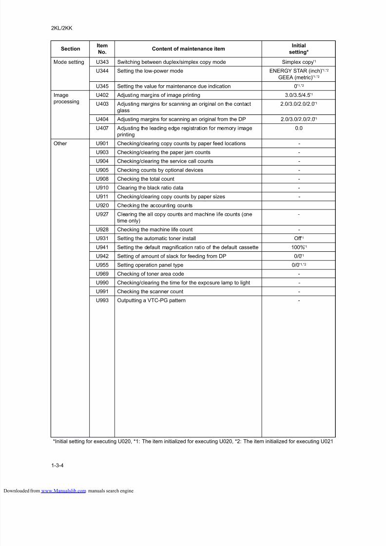
Mode setting U343 Switching between duplex/simplex copy mode Simplex copy*1
U344 Setting the low-power mode ENERGY STAR (inch)*1,*2
GEEA (metric)*1,*2
U345 Setting the value for maintenance due indication 0*1,*2
Imageprocessing
U402 Adjusting margins of image printing 3.0/3.5/4.5*1
U403 Adjusting margins for scanning an original on the contact
glass
2.0/3.0/2.0/2.0*1
U404 Adjusting margins for scanning an original from the DP 2.0/3.0/2.0/2.0*1
U407 Adjusting the leading edge registration for memory image
printing
0.0
Other U901 Checking/clearing copy counts by paper feed locations -
U903 Checking/clearing the paper jam counts -
U904 Checking/clearing the service call counts -
U905 Checking counts by optional devices -
U908 Checking the total count -
U910 Clearing the black ratio data -
U911 Checking/clearing copy counts by paper sizes -
U920 Checking the accounting counts
U927 Clearing the all copy counts and machine life counts (one
time only)
-
U928 Checking the machine life count -
U931 Setting the automatic toner install Off *1
U941 Setting the default magnification ratio of the default cassette 100%*1
U942 Setting of amount of slack for feeding from DP 0/0*1
U955 Setting operation panel type 0/0*1,*2
U969 Checking of toner area code -
U990 Checking/clearing the time for the exposure lamp to light -
U991 Checking the scanner count -
U993 Outputting a VTC-PG pattern -
SectionItem
No.Content of maintenance item
Initial
setting*
*Initial setting for executing U020, *1: The item initialized for executing U020, *2: The item initialized for executing U021
loaded from www.Manualslib.com manuals search engine
8/18/2019 taskalfa_220
http://slidepdf.com/reader/full/taskalfa220 43/300
2KL/2KK
1-3-5
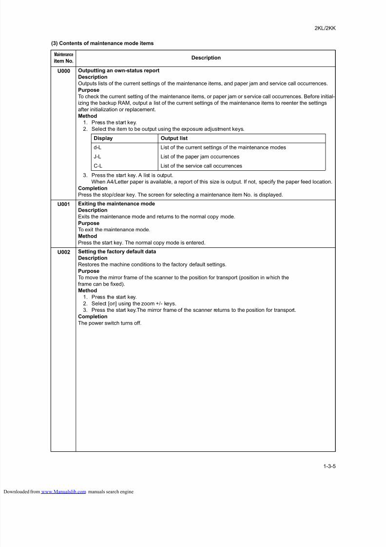
(3) Contents of maintenance mode items
Maintenance
item No.Description
U000 Outputting an own-status report
Description
Outputs lists of the current settings of the maintenance items, and paper jam and service call occurrences.
Purpose
To check the current setting of the maintenance items, or paper jam or service call occurrences. Before initial-izing the backup RAM, output a list of the current settings of the maintenance items to reenter the settings
after initialization or replacement.
Method
1. Press the start key.
2. Select the item to be output using the exposure adjustment keys.
3. Press the start key. A list is output.
When A4/Letter paper is available, a report of this size is output. If not, specify the paper feed location.
Completion
Press the stop/clear key. The screen for selecting a maintenance item No. is displayed.
U001 Exiting the maintenance mode
Description
Exits the maintenance mode and returns to the normal copy mode.
Purpose
To exit the maintenance mode.
Method
Press the start key. The normal copy mode is entered.
U002 Setting the factory default data
Description
Restores the machine conditions to the factory default settings.
Purpose
To move the mirror frame of the scanner to the position for transport (position in which the
frame can be fixed).
Method
1. Press the start key.
2. Select [on] using the zoom +/- keys.
3. Press the start key.The mirror frame of the scanner returns to the position for transport.
Completion
The power switch turns off.
Display Output list
d-L List of the current settings of the maintenance modes
J-L List of the paper jam occurrences
C-L List of the service call occurrences
loaded from www.Manualslib.com manuals search engine

8/18/2019 taskalfa_220
http://slidepdf.com/reader/full/taskalfa220 44/300
2KL/2KK
1-3-6
U004 Checking the machine number
Description
Displays the machine number.
Purpose
To check the machine number.
Method1. Press the start key.
2. Change the indication of the copy quantity display using the exposure adjustment keys.
Code Corresponding Table
Completion
Press the stop/clear key. The screen for selecting a maintenance item No. is displayed.
Maintenance
item No.Description
Exposure indicator Copy quantity display
Exp. 1 (lit) 1st digit of machine number
Exp. 2 (lit) 2nd digit of machine number
Exp. 3 (lit) 3rd digit of machine number
Exp. 4 (lit) 4th digit of machine number
Exp. 5 (lit) 5th digit of machine number
Exp. 1 (flashing) 6th digit of machine number
Exp. 2 (flashing) 7th digit of machine number
Exp. 3 (flashing) 8th digit of machine number Exp. 4 (flashing) 9th digit of machine number
Exp. 5 (flashing) 10th digit of machine number
0: 30 A: 41 K: 4B U: 55
1: 31 B: 42 L: 4C V: 56
2: 32 C: 43 M: 4D W: 57
3: 33 D: 44 N: 4E X: 58
4: 34 E: 45 O: 4F Y: 59
5: 35 F: 46 P: 50 Z: 5A
6: 36 G: 47 Q: 51
7: 37 H: 48 R: 52
8: 38 I: 49 S: 53
9: 39 J: 4A T: 54
loaded from www.Manualslib.com manuals search engine
8/18/2019 taskalfa_220
http://slidepdf.com/reader/full/taskalfa220 45/300
2KL/2KK
1-3-7
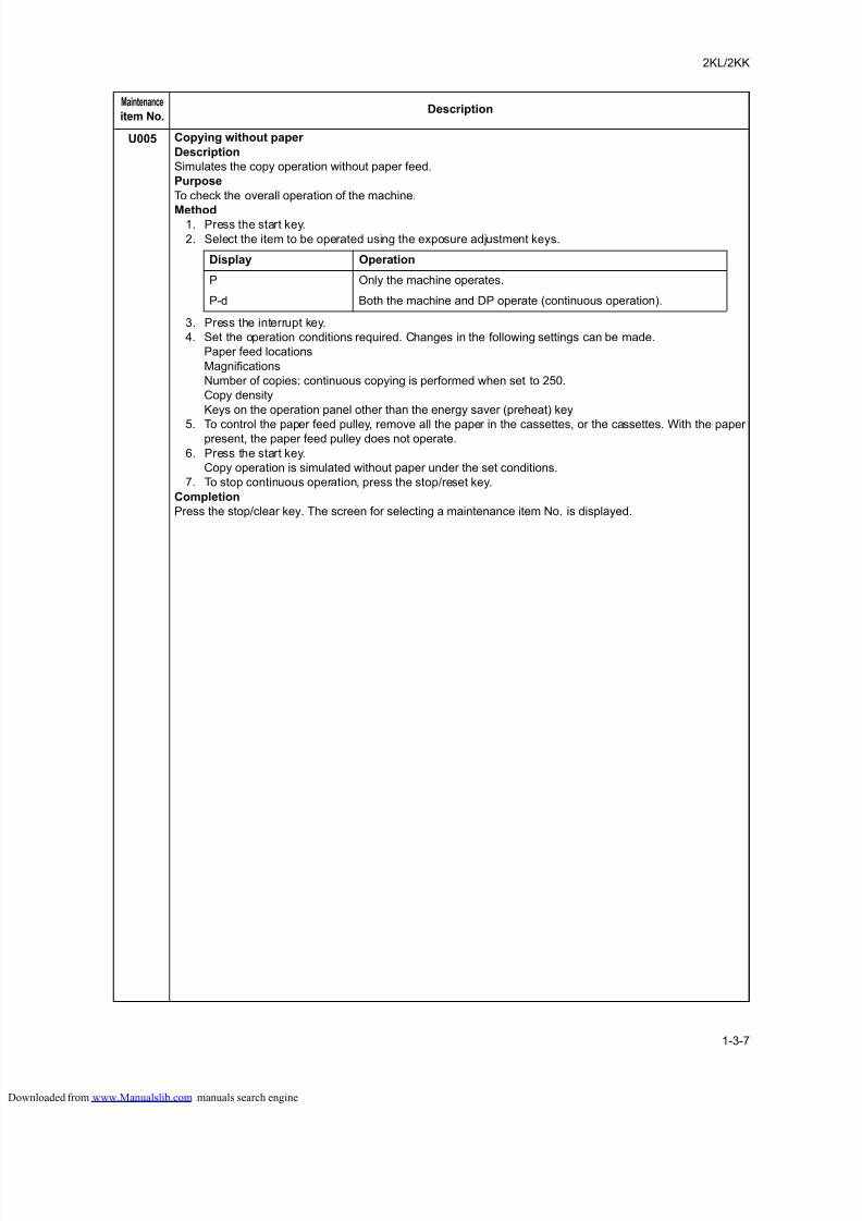
U005 Copying without paper
Description
Simulates the copy operation without paper feed.
Purpose
To check the overall operation of the machine.
Method1. Press the start key.
2. Select the item to be operated using the exposure adjustment keys.
3. Press the interrupt key.
4. Set the operation conditions required. Changes in the following settings can be made.
Paper feed locations
Magnifications
Number of copies: continuous copying is performed when set to 250.
Copy density
Keys on the operation panel other than the energy saver (preheat) key
5. To control the paper feed pulley, remove all the paper in the cassettes, or the cassettes. With the paperpresent, the paper feed pulley does not operate.
6. Press the start key.
Copy operation is simulated without paper under the set conditions.
7. To stop continuous operation, press the stop/reset key.
Completion
Press the stop/clear key. The screen for selecting a maintenance item No. is displayed.
Maintenance
item No.Description
Display Operation
P Only the machine operates.
P-d Both the machine and DP operate (continuous operation).
loaded from www.Manualslib.com manuals search engine
8/18/2019 taskalfa_220
http://slidepdf.com/reader/full/taskalfa220 46/300
2KL/2KK
1-3-8
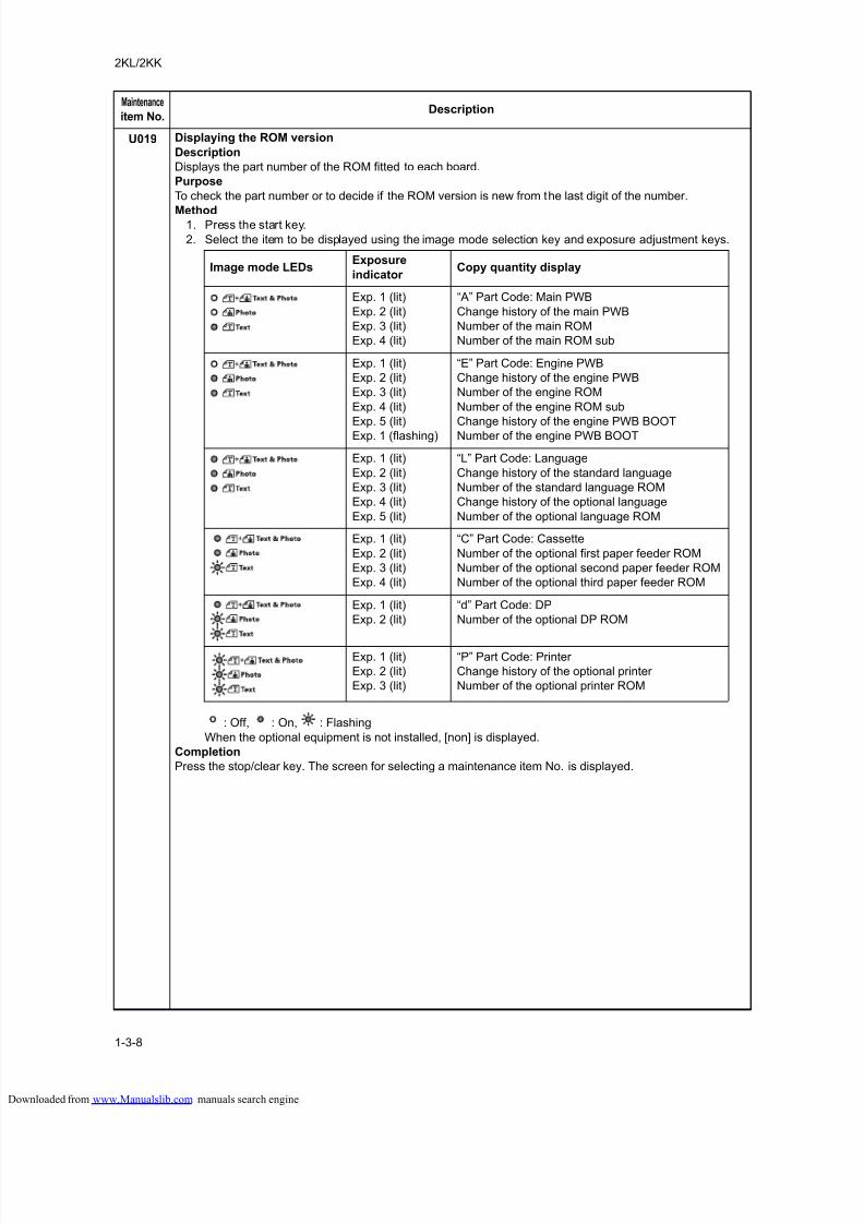
U019 Displaying the ROM version
Description
Displays the part number of the ROM fitted to each board.
Purpose
To check the part number or to decide if the ROM version is new from the last digit of the number.
Method1. Press the start key.
2. Select the item to be displayed using the image mode selection key and exposure adjustment keys.
: Off, : On, : Flashing
When the optional equipment is not installed, [non] is displayed.
Completion
Press the stop/clear key. The screen for selecting a maintenance item No. is displayed.
Maintenance
item No.Description
Image mode LEDsExposure
indicator Copy quantity display
Exp. 1 (lit)
Exp. 2 (lit)
Exp. 3 (lit)
Exp. 4 (lit)
“A” Part Code: Main PWB
Change history of the main PWB
Number of the main ROM
Number of the main ROM sub
Exp. 1 (lit)
Exp. 2 (lit)
Exp. 3 (lit)
Exp. 4 (lit)
Exp. 5 (lit)
Exp. 1 (flashing)
“E” Part Code: Engine PWB
Change history of the engine PWB
Number of the engine ROM
Number of the engine ROM sub
Change history of the engine PWB BOOT
Number of the engine PWB BOOT
Exp. 1 (lit)
Exp. 2 (lit)
Exp. 3 (lit)
Exp. 4 (lit)
Exp. 5 (lit)
“L” Part Code: Language
Change history of the standard language
Number of the standard language ROM
Change history of the optional language
Number of the optional language ROM
Exp. 1 (lit)
Exp. 2 (lit)
Exp. 3 (lit)
Exp. 4 (lit)
“C” Part Code: Cassette
Number of the optional first paper feeder ROM
Number of the optional second paper feeder ROM
Number of the optional third paper feeder ROM
Exp. 1 (lit)
Exp. 2 (lit)
“d” Part Code: DP
Number of the optional DP ROM
Exp. 1 (lit)
Exp. 2 (lit)
Exp. 3 (lit)
“P” Part Code: Printer
Change history of the optional printer
Number of the optional printer ROM
loaded from www.Manualslib.com manuals search engine
8/18/2019 taskalfa_220
http://slidepdf.com/reader/full/taskalfa220 47/300
2KL/2KK
1-3-9
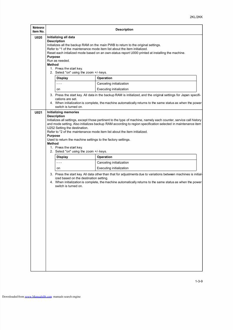
U020 Initializing all data
Description
Initializes all the backup RAM on the main PWB to return to the original settings.
Refer to *1 of the maintenance mode item list about the item initialized.
Reset each intialized mode based on an own-status report U000 printed at installing the machine.
PurposeRun as needed.
Method
1. Press the start key.
2. Select "on" using the zoom +/- keys.
3. Press the start key. All data in the backup RAM is initialized, and the original settings for Japan specifi-
cations are set.
4. When initialization is complete, the machine automatically returns to the same status as when the power
switch is turned on.
U021 Initializing memories
DescriptionInitializes all settings, except those pertinent to the type of machine, namely each counter, service call history
and mode setting. Also initializes backup RAM according to region specification selected in maintenance item
U252 Setting the destination.
Refer to *2 of the maintenance mode item list about the item initialized.
Purpose
Used to return the machine settings to the factory settings.
Method
1. Press the start key.
2. Select "on" using the zoom +/- keys.
3. Press the start key. All data other than that for adjustments due to variations between machines is initial-ized based on the destination setting.
4. When initialization is complete, the machine automatically returns to the same status as when the power
switch is turned on.
Maintenance
item No.Description
Display Operation
- - - Canceling initialization
on Executing initialization
Display Operation
- - - Canceling initialization
on Executing initialization
loaded from www.Manualslib.com manuals search engine
8/18/2019 taskalfa_220
http://slidepdf.com/reader/full/taskalfa220 48/300
2KL/2KK
1-3-10
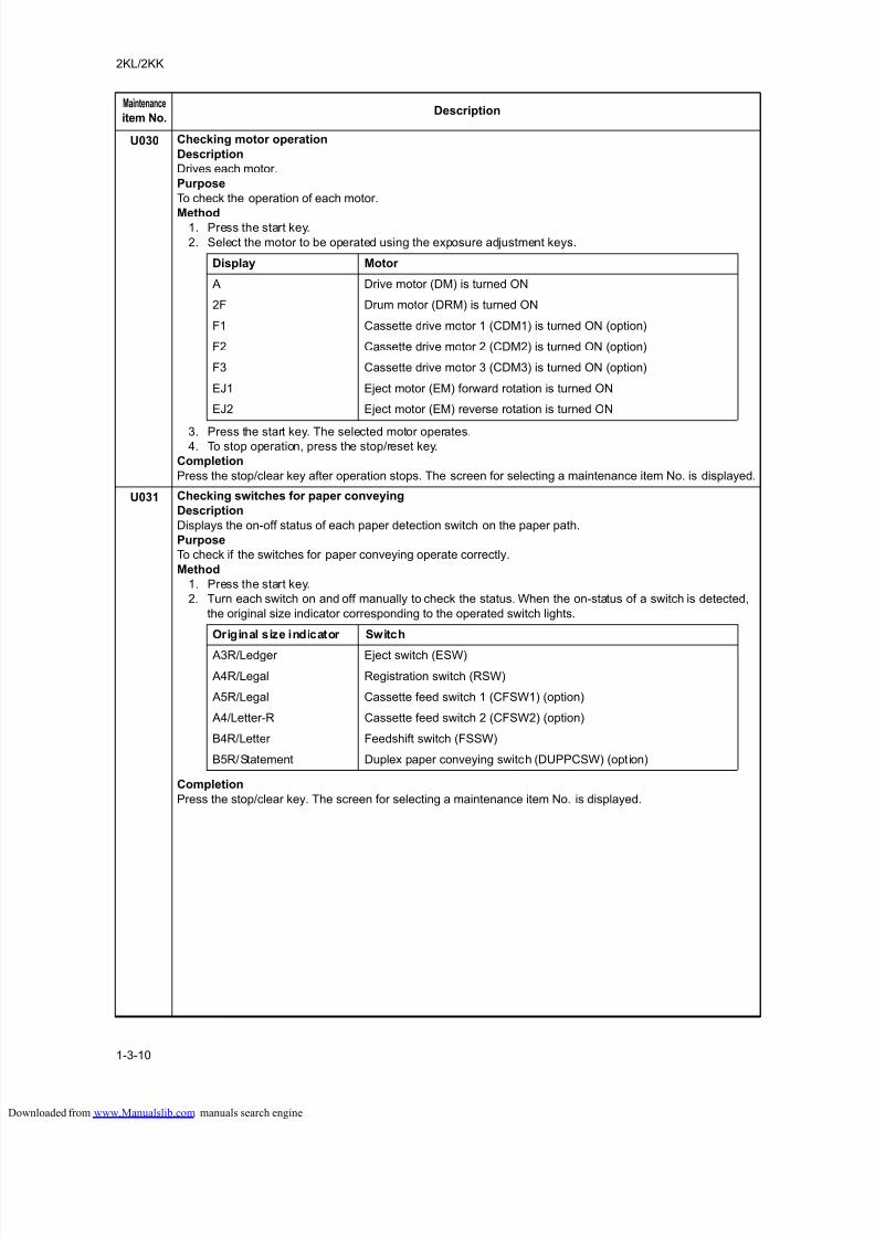
U030 Checking motor operation
Description
Drives each motor.
Purpose
To check the operation of each motor.
Method1. Press the start key.
2. Select the motor to be operated using the exposure adjustment keys.
3. Press the start key. The selected motor operates.4. To stop operation, press the stop/reset key.
Completion
Press the stop/clear key after operation stops. The screen for selecting a maintenance item No. is displayed.
U031 Checking switches for paper conveying
Description
Displays the on-off status of each paper detection switch on the paper path.
Purpose
To check if the switches for paper conveying operate correctly.
Method
1. Press the start key.
2. Turn each switch on and off manually to check the status. When the on-status of a switch is detected,
the original size indicator corresponding to the operated switch lights.
Completion
Press the stop/clear key. The screen for selecting a maintenance item No. is displayed.
Maintenance
item No.Description
Display Motor
A Drive motor (DM) is turned ON
2F Drum motor (DRM) is turned ON
F1 Cassette drive motor 1 (CDM1) is turned ON (option)
F2 Cassette drive motor 2 (CDM2) is turned ON (option)
F3 Cassette drive motor 3 (CDM3) is turned ON (option)
EJ1 Eject motor (EM) forward rotation is turned ON
EJ2 Eject motor (EM) reverse rotation is turned ON
Original size indicator Switch
A3R/Ledger Eject switch (ESW)
A4R/Legal Registration switch (RSW)
A5R/Legal Cassette feed switch 1 (CFSW1) (option)
A4/Letter-R Cassette feed switch 2 (CFSW2) (option)
B4R/Letter Feedshift switch (FSSW)
B5R/Statement Duplex paper conveying switch (DUPPCSW) (option)
loaded from www.Manualslib.com manuals search engine
8/18/2019 taskalfa_220
http://slidepdf.com/reader/full/taskalfa220 49/300
2KL/2KK
1-3-11
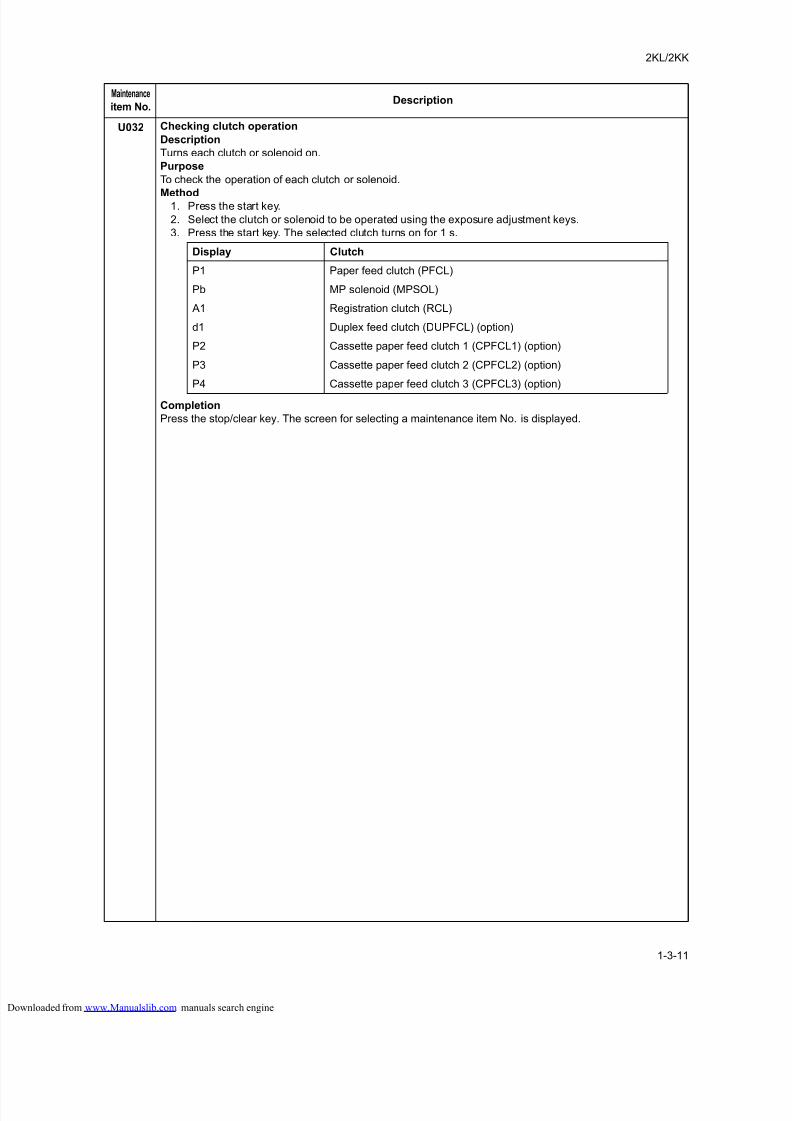
U032 Checking clutch operation
Description
Turns each clutch or solenoid on.
Purpose
To check the operation of each clutch or solenoid.
Method1. Press the start key.
2. Select the clutch or solenoid to be operated using the exposure adjustment keys.
3. Press the start key. The selected clutch turns on for 1 s.
Completion
Press the stop/clear key. The screen for selecting a maintenance item No. is displayed.
Maintenance
item No.Description
Display Clutch
P1 Paper feed clutch (PFCL)
Pb MP solenoid (MPSOL)
A1 Registration clutch (RCL)
d1 Duplex feed clutch (DUPFCL) (option)
P2 Cassette paper feed clutch 1 (CPFCL1) (option)
P3 Cassette paper feed clutch 2 (CPFCL2) (option)
P4 Cassette paper feed clutch 3 (CPFCL3) (option)
loaded from www.Manualslib.com manuals search engine
8/18/2019 taskalfa_220
http://slidepdf.com/reader/full/taskalfa220 50/300
2KL/2KK
1-3-12
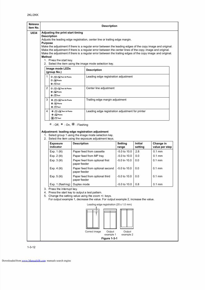
U034 Adjusting the print start timing
Description
Adjusts the leading edge registration, center line or trailing edge margin.
Purpose
Make the adjustment if there is a regular error between the leading edges of the copy image and original.
Make the adjustment if there is a regular error between the center lines of the copy image and original.Make the adjustment if there is a regular error between the trailing edges of the copy image and original.
Method
1. Press the start key.
2. Select the item using the image mode selection key.
: Off, : On, : Flashing
Adjustment: leading edge registration adjustment
1. Select group 1 using the image mode selection key.
2. Select the item using the exposure adjustment keys.
3. Press the interrupt key.
4. Press the start key to output a test pattern.
5. Change the setting value using the zoom +/- keys.
For output example 1, decrease the value. For output example 2, increase the value.
Figure 1-3-1
Maintenance
item No.Description
Image mode LEDs
(group No.)Description
1 Leading edge registration adjustment
2 Center line adjustment
3 Trailing edge margin adjustment
4 Leading edge registration adjustment for printer
Exposure
indicator
Description Setting
range
Initial
setting
Change in
value per step
Exp. 1 (lit) Paper feed from cassette -5.0 to 10.0 2.8 0.1 mmExp. 2 (lit) Paper feed from MP tray -5.0 to 10.0 0.0 0.1 mm
Exp. 3 (lit) Paper feed from optional first
paper feeder
-5.0 to 10.0 0.0 0.1 mm
Exp. 4 (lit) Paper feed from optional second
paper feeder
-5.0 to 10.0 0.0 0.1 mm
Exp. 5 (lit) Paper feed from optional third
paper feeder
-5.0 to 10.0 0.0 0.1 mm
Exp. 1 (flashing) Duplex mode -5.0 to 10.0 0.8 0.1 mm
Correct image Outputexample 1
Outputexample 2
Leading edge registration (20 ± 1.0 mm)
loaded from www.Manualslib.com manuals search engine
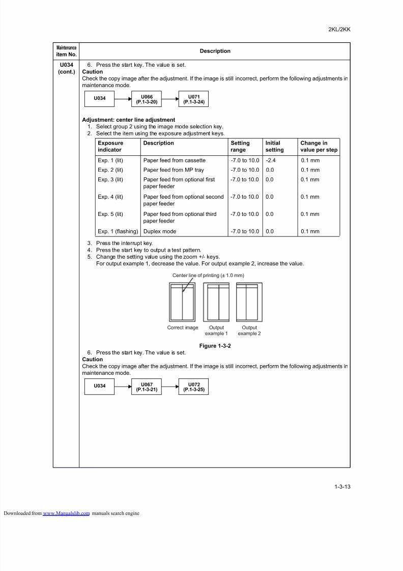
8/18/2019 taskalfa_220
http://slidepdf.com/reader/full/taskalfa220 51/300
2KL/2KK
1-3-13
U034
(cont.)
6. Press the start key. The value is set.
Caution
Check the copy image after the adjustment. If the image is still incorrect, perform the following adjustments in
maintenance mode.
Adjustment: center line adjustment
1. Select group 2 using the image mode selection key.
2. Select the item using the exposure adjustment keys.
3. Press the interrupt key.
4. Press the start key to output a test pattern.
5. Change the setting value using the zoom +/- keys.
For output example 1, decrease the value. For output example 2, increase the value.
Figure 1-3-2
6. Press the start key. The value is set.
Caution
Check the copy image after the adjustment. If the image is still incorrect, perform the following adjustments in
maintenance mode.
Maintenance
item No.Description
U034U066
(P.1-3-20)U071
(P.1-3-24)
Exposure
indicator
Description Setting
range
Initial
setting
Change in
value per step
Exp. 1 (lit) Paper feed from cassette -7.0 to 10.0 -2.4 0.1 mm
Exp. 2 (lit) Paper feed from MP tray -7.0 to 10.0 0.0 0.1 mm
Exp. 3 (lit) Paper feed from optional first
paper feeder
-7.0 to 10.0 0.0 0.1 mm
Exp. 4 (lit) Paper feed from optional second
paper feeder
-7.0 to 10.0 0.0 0.1 mm
Exp. 5 (lit) Paper feed from optional third
paper feeder
-7.0 to 10.0 0.0 0.1 mm
Exp. 1 (flashing) Duplex mode -7.0 to 10.0 0.0 0.1 mm
Center line of printing (± 1.0 mm)
Correct image Outputexample 1
Outputexample 2
U034 U067(P.1-3-21)
U072(P.1-3-25)
loaded from www.Manualslib.com manuals search engine
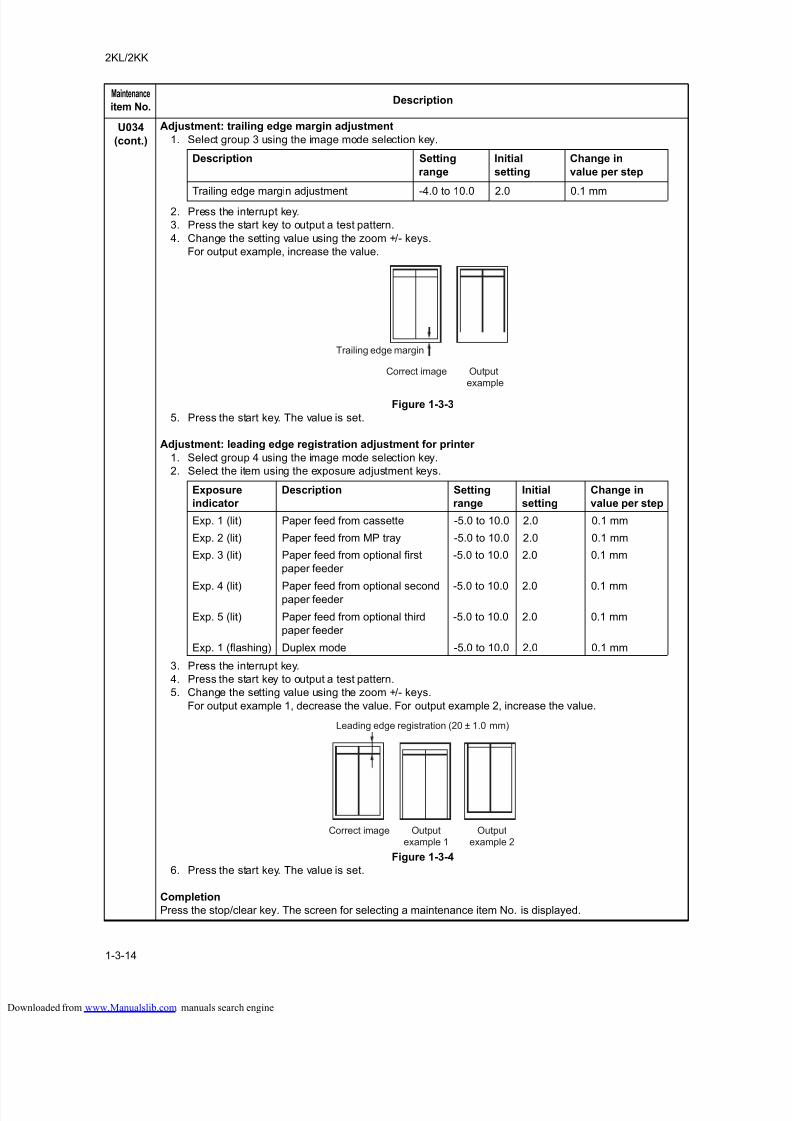
8/18/2019 taskalfa_220
http://slidepdf.com/reader/full/taskalfa220 52/300
2KL/2KK
1-3-14
U034
(cont.)
Adjustment: trailing edge margin adjustment
1. Select group 3 using the image mode selection key.
2. Press the interrupt key.
3. Press the start key to output a test pattern.
4. Change the setting value using the zoom +/- keys.
For output example, increase the value.
Figure 1-3-3
5. Press the start key. The value is set.
Adjustment: leading edge registration adjustment for printer
1. Select group 4 using the image mode selection key.
2. Select the item using the exposure adjustment keys.
3. Press the interrupt key.
4. Press the start key to output a test pattern.
5. Change the setting value using the zoom +/- keys.
For output example 1, decrease the value. For output example 2, increase the value.
Figure 1-3-4
6. Press the start key. The value is set.
Completion
Press the stop/clear key. The screen for selecting a maintenance item No. is displayed.
Maintenance
item No.Description
Description Setting
range
Initial
setting
Change in
value per step
Trailing edge margin adjustment -4.0 to 10.0 2.0 0.1 mm
Correct image Outputexample
Trailing edge margin
Exposure
indicator
Description Setting
range
Initial
setting
Change in
value per step
Exp. 1 (lit) Paper feed from cassette -5.0 to 10.0 2.0 0.1 mm
Exp. 2 (lit) Paper feed from MP tray -5.0 to 10.0 2.0 0.1 mm
Exp. 3 (lit) Paper feed from optional first
paper feeder
-5.0 to 10.0 2.0 0.1 mm
Exp. 4 (lit) Paper feed from optional secondpaper feeder
-5.0 to 10.0 2.0 0.1 mm
Exp. 5 (lit) Paper feed from optional third
paper feeder
-5.0 to 10.0 2.0 0.1 mm
Exp. 1 (flashing) Duplex mode -5.0 to 10.0 2.0 0.1 mm
Correct image Outputexample 1
Outputexample 2
Leading edge registration (20 ± 1.0 mm)
loaded from www.Manualslib.com manuals search engine
8/18/2019 taskalfa_220
http://slidepdf.com/reader/full/taskalfa220 53/300
2KL/2KK
1-3-15
U035 Setting folio size
Description
Changes the image area for copying onto folio size paper.
Purpose
To prevent the image at the trailing edge, or right or left side of the paper from not being copied by setting the
actual size of the folio paper used.Method
Press the start key.
Setting
1. Select the item to be set using the exposure adjustment keys.
2. Change the setting using the zoom +/- keys.
3. Press the start key. The value is set.
Completion
Press the stop/clear key. The screen for selecting a maintenance item No. is displayed.
Maintenance
item No.Description
Exposure indicator Setting Setting range Initial setting
Exp. 1 Length 330 to 356 mm 330
Exp. 2 Width 200 to 220 mm 210
loaded from www.Manualslib.com manuals search engine
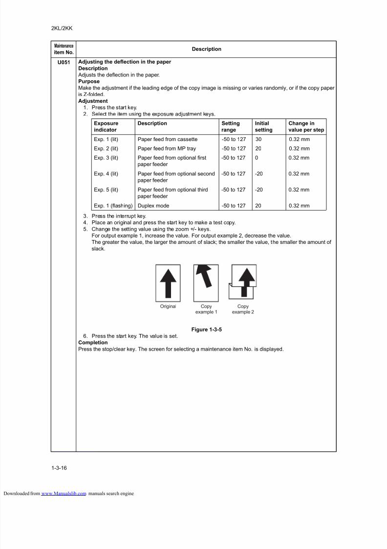
8/18/2019 taskalfa_220
http://slidepdf.com/reader/full/taskalfa220 54/300
2KL/2KK
1-3-16
U051 Adjusting the deflection in the paper
Description
Adjusts the deflection in the paper.
Purpose
Make the adjustment if the leading edge of the copy image is missing or varies randomly, or if the copy paper
is Z-folded.Adjustment
1. Press the start key.
2. Select the item using the exposure adjustment keys.
3. Press the interrupt key.
4. Place an original and press the start key to make a test copy.
5. Change the setting value using the zoom +/- keys.
For output example 1, increase the value. For output example 2, decrease the value.
The greater the value, the larger the amount of slack; the smaller the value, the smaller the amount of
slack.
Figure 1-3-5
6. Press the start key. The value is set.
Completion
Press the stop/clear key. The screen for selecting a maintenance item No. is displayed.
Maintenance
item No.Description
Exposure
indicator
Description Setting
range
Initial
setting
Change in
value per step
Exp. 1 (lit) Paper feed from cassette -50 to 127 30 0.32 mm
Exp. 2 (lit) Paper feed from MP tray -50 to 127 20 0.32 mm
Exp. 3 (lit) Paper feed from optional first
paper feeder
-50 to 127 0 0.32 mm
Exp. 4 (lit) Paper feed from optional second
paper feeder
-50 to 127 -20 0.32 mm
Exp. 5 (lit) Paper feed from optional thirdpaper feeder -50 to 127 -20 0.32 mm
Exp. 1 (flashing) Duplex mode -50 to 127 20 0.32 mm
Original Copyexample 1
Copyexample 2
loaded from www.Manualslib.com manuals search engine
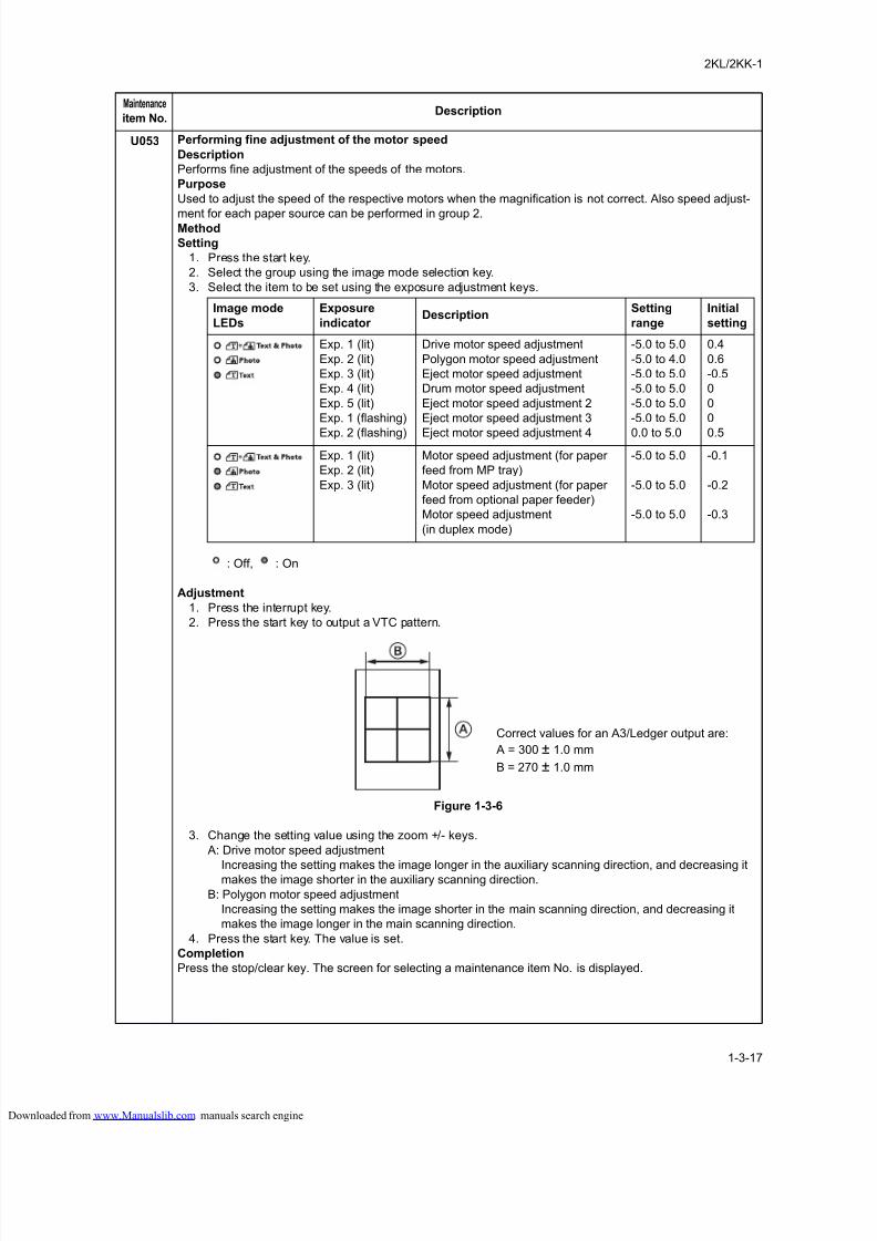
8/18/2019 taskalfa_220
http://slidepdf.com/reader/full/taskalfa220 55/300
2KL/2KK-1
1-3-17
U053 Performing fine adjustment of the motor speed
Description
Performs fine adjustment of the speeds of the motors.
Purpose
Used to adjust the speed of the respective motors when the magnification is not correct. Also speed adjust-
ment for each paper source can be performed in group 2.Method
Setting
1. Press the start key.
2. Select the group using the image mode selection key.
3. Select the item to be set using the exposure adjustment keys.
: Off, : On
Adjustment
1. Press the interrupt key.
2. Press the start key to output a VTC pattern.
Figure 1-3-6
3. Change the setting value using the zoom +/- keys.
A: Drive motor speed adjustment
Increasing the setting makes the image longer in the auxiliary scanning direction, and decreasing itmakes the image shorter in the auxiliary scanning direction.
B: Polygon motor speed adjustment
Increasing the setting makes the image shorter in the main scanning direction, and decreasing it
makes the image longer in the main scanning direction.
4. Press the start key. The value is set.
Completion
Press the stop/clear key. The screen for selecting a maintenance item No. is displayed.
Maintenance
item No.Description
Image mode
LEDs
Exposure
indicator Description
Setting
range
Initial
setting
Exp. 1 (lit)
Exp. 2 (lit)
Exp. 3 (lit)
Exp. 4 (lit)
Exp. 5 (lit)
Exp. 1 (flashing)
Exp. 2 (flashing)
Drive motor speed adjustment
Polygon motor speed adjustment
Eject motor speed adjustment
Drum motor speed adjustment
Eject motor speed adjustment 2
Eject motor speed adjustment 3
Eject motor speed adjustment 4
-5.0 to 5.0
-5.0 to 4.0
-5.0 to 5.0
-5.0 to 5.0
-5.0 to 5.0
-5.0 to 5.0
0.0 to 5.0
0.4
0.6
-0.5
0
0
0
0.5
Exp. 1 (lit)
Exp. 2 (lit)
Exp. 3 (lit)
Motor speed adjustment (for paper
feed from MP tray)
Motor speed adjustment (for paper
feed from optional paper feeder)
Motor speed adjustment
(in duplex mode)
-5.0 to 5.0
-5.0 to 5.0
-5.0 to 5.0
-0.1
-0.2
-0.3
Correct values for an A3/Ledger output are:
A = 300 ± 1.0 mm
B = 270 ± 1.0 mm
loaded from www.Manualslib.com manuals search engine
8/18/2019 taskalfa_220
http://slidepdf.com/reader/full/taskalfa220 56/300
2KL/2KK
1-3-18
U060 Adjusting the scanner input properties
Description
Adjusts the image scanning density.
Purpose
Used when the entire image appears too dark or light.
MethodPress the start key.
Setting
1. Press the start key.
2. Change the setting using the zoom +/- keys.
Increasing the setting makes the density lower, and decreasing it makes the density higher.
3. Press the start key. The value is set.
Supplement
While this maintenance item is being executed, copying from an original is available in interrupt copying mode
(which is activated by pressing the interrupt key).
Completion
Press the stop/clear key. The screen for selecting a maintenance item No. is displayed.
Caution
The following settings are also reset to the initial values by performing this maintenance item:
Exposure density gradient set in maintenance mode (U093)
Exposure set in the copy default item of the copier management mode
U061 Turning the exposure lamp on
Description
Turns the exposure lamp on.
Purpose
To check the exposure lamp.
Method
1. Press the start key. "on" appears.
2. Press the start key. The exposure lamp lights.
3. To turn the exposure lamp off, press the stop/clear key.
Completion
Press the stop/clear key. The screen for selecting a maintenance item No. is displayed.
U063 Adjusting the shading position
Description
Changes the shading position.
Purpose
Used when white lines continue to appear longitudinally on the image after the shading plate is cleaned. This
is due to flaws or stains inside the shading plate. To prevent this problem, the shading position should be
changed so that shading is possible without being affected by the flaws or stains.
Setting
1. Press the start key.
2. Change the setting using the zoom +/- keys.
Increasing the setting moves the shading position toward the machine left, and decreasing it moves theposition toward the machine right.
3. Press the start key. The value is set.
Supplement
While this maintenance item is being executed, copying from an original is available in interrupt copying mode
(which is activated by pressing the interrupt key).
Completion
Press the stop/clear key. The screen for selecting a maintenance item No. is displayed.
Maintenance
item No.Description
Description Setting range Initial setting
Image scanning density 0 to 23 12
Description Setting range Initial setting Change in value per step
Shading position -5 to 5 0 0.17 mm
loaded from www.Manualslib.com manuals search engine
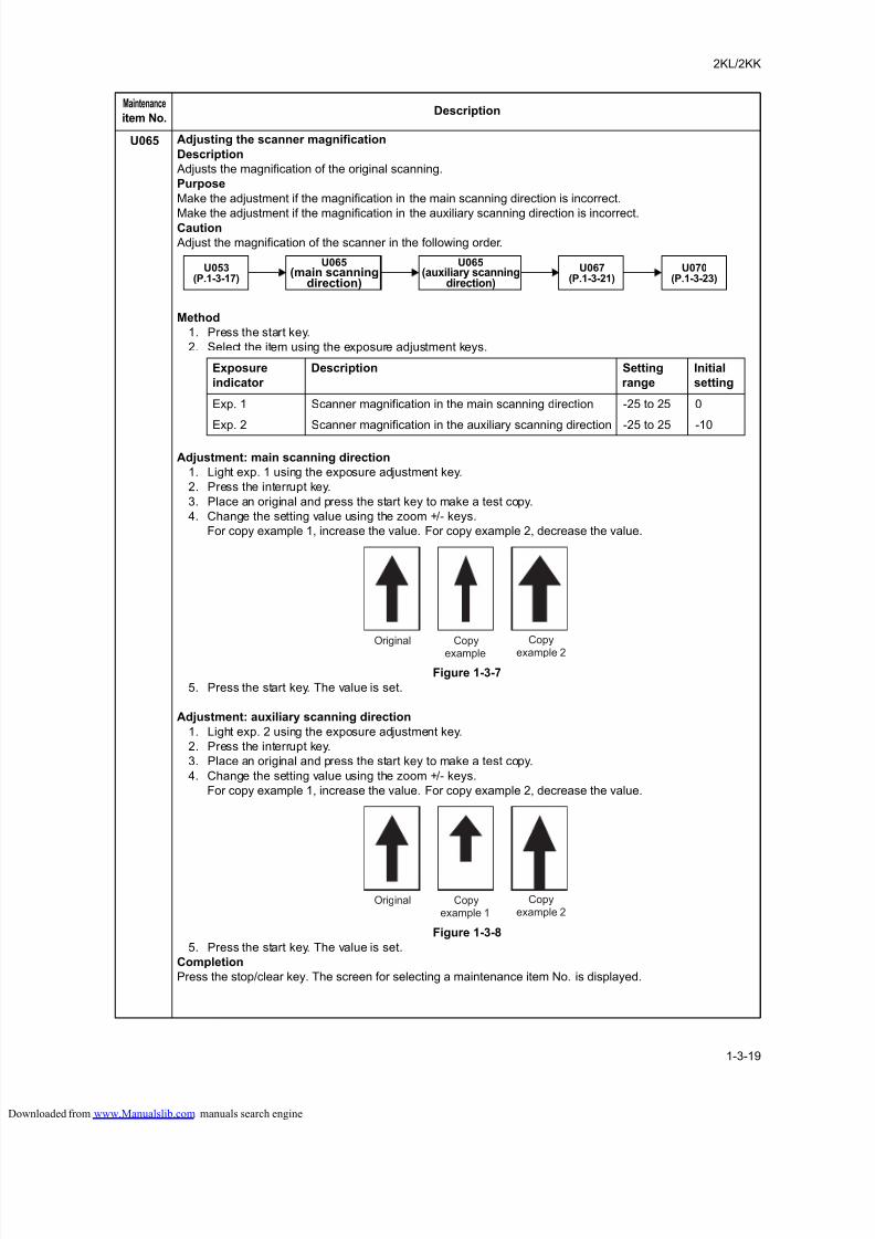
8/18/2019 taskalfa_220
http://slidepdf.com/reader/full/taskalfa220 57/300
2KL/2KK
1-3-19
U065 Adjusting the scanner magnification
Description
Adjusts the magnification of the original scanning.
Purpose
Make the adjustment if the magnification in the main scanning direction is incorrect.
Make the adjustment if the magnification in the auxiliary scanning direction is incorrect.Caution
Adjust the magnification of the scanner in the following order.
Method
1. Press the start key.
2. Select the item using the exposure adjustment keys.
Adjustment: main scanning direction
1. Light exp. 1 using the exposure adjustment key.
2. Press the interrupt key.
3. Place an original and press the start key to make a test copy.
4. Change the setting value using the zoom +/- keys.
For copy example 1, increase the value. For copy example 2, decrease the value.
Figure 1-3-7
5. Press the start key. The value is set.
Adjustment: auxiliary scanning direction
1. Light exp. 2 using the exposure adjustment key.
2. Press the interrupt key.
3. Place an original and press the start key to make a test copy.
4. Change the setting value using the zoom +/- keys.
For copy example 1, increase the value. For copy example 2, decrease the value.
Figure 1-3-8
5. Press the start key. The value is set.
Completion
Press the stop/clear key. The screen for selecting a maintenance item No. is displayed.
Maintenance
item No.Description
U065(main scanning
direction)
U053(P.1-3-17)
U067(P.1-3-21)
U065(auxiliary scanning
direction)
U070(P.1-3-23)
Exposure
indicator
Description Setting
range
Initial
setting
Exp. 1 Scanner magnification in the main scanning direction -25 to 25 0
Exp. 2 Scanner magnification in the auxiliary scanning direction -25 to 25 -10
Original Copy
example
Copy
example 2
Original Copyexample 1
Copyexample 2
loaded from www.Manualslib.com manuals search engine
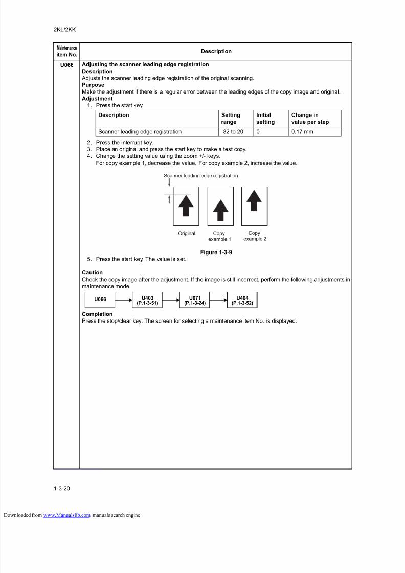
8/18/2019 taskalfa_220
http://slidepdf.com/reader/full/taskalfa220 58/300
2KL/2KK
1-3-20
U066 Adjusting the scanner leading edge registration
Description
Adjusts the scanner leading edge registration of the original scanning.
Purpose
Make the adjustment if there is a regular error between the leading edges of the copy image and original.
Adjustment1. Press the start key.
2. Press the interrupt key.
3. Place an original and press the start key to make a test copy.
4. Change the setting value using the zoom +/- keys.
For copy example 1, decrease the value. For copy example 2, increase the value.
Figure 1-3-9
5. Press the start key. The value is set.
Caution
Check the copy image after the adjustment. If the image is still incorrect, perform the following adjustments in
maintenance mode.
Completion
Press the stop/clear key. The screen for selecting a maintenance item No. is displayed.
Maintenance
item No.Description
Description Setting
range
Initial
setting
Change in
value per step
Scanner leading edge registration -32 to 20 0 0.17 mm
Original Copyexample 1
Copyexample 2
Scanner leading edge registration
U066U403
(P.1-3-51)U071
(P.1-3-24)U404
(P.1-3-52)
loaded from www.Manualslib.com manuals search engine
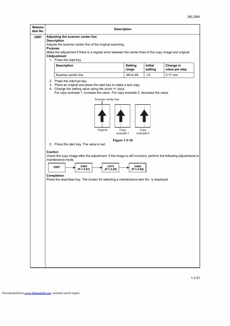
8/18/2019 taskalfa_220
http://slidepdf.com/reader/full/taskalfa220 59/300
2KL/2KK
1-3-21
U067 Adjusting the scanner center line
Description
Adjusts the scanner center line of the original scanning.
Purpose
Make the adjustment if there is a regular error between the center lines of the copy image and original.
CAdjustment1. Press the start key.
2. Press the interrupt key.
3. Place an original and press the start key to make a test copy.
4. Change the setting value using the zoom +/- keys.
For copy example 1, increase the value. For copy example 2, decrease the value.
Figure 1-3-10
5. Press the start key. The value is set.
Caution
Check the copy image after the adjustment. If the image is still incorrect, perform the following adjustments in
maintenance mode.
Completion
Press the stop/clear key. The screen for selecting a maintenance item No. is displayed.
Maintenance
item No.Description
Description Setting
range
Initial
setting
Change in
value per step
Scanner center line -66 to 66 -10 0.17 mm
Original Copyexample 1
Copyexample 2
Scanner center line
U067 U403(P.1-3-51)
U072(P.1-3-25)
U404(P.1-3-52)
loaded from www.Manualslib.com manuals search engine
8/18/2019 taskalfa_220
http://slidepdf.com/reader/full/taskalfa220 60/300
2KL/2KK
1-3-22
U068 Adjusting the scanning position for originals from the DP
Description
Adjusts the position for scanning originals from the DP.
Purpose
Used when the image fogging occurs because the scanning position is not proper when the DP is used. Run
U071 to adjust the timing of DP leading edge when the scanning position is changed.Setting
1. Press the start key.
2. Change the setting using the zoom +/- keys.
Increasing the value moves the image backward, and decreasing it moves the image forward.
Supplement
While this maintenance item is being executed, copying from an original is available in interrupt copying mode
(which is activated by pressing the interrupt key).
Completion
Press the stop/clear key. The screen for selecting a maintenance item No. is displayed.
Maintenance
item No.Description
Description Setting range Initial setting Change in value per step
Scanning position -17 to 17 0 0.17 mm
loaded from www.Manualslib.com manuals search engine
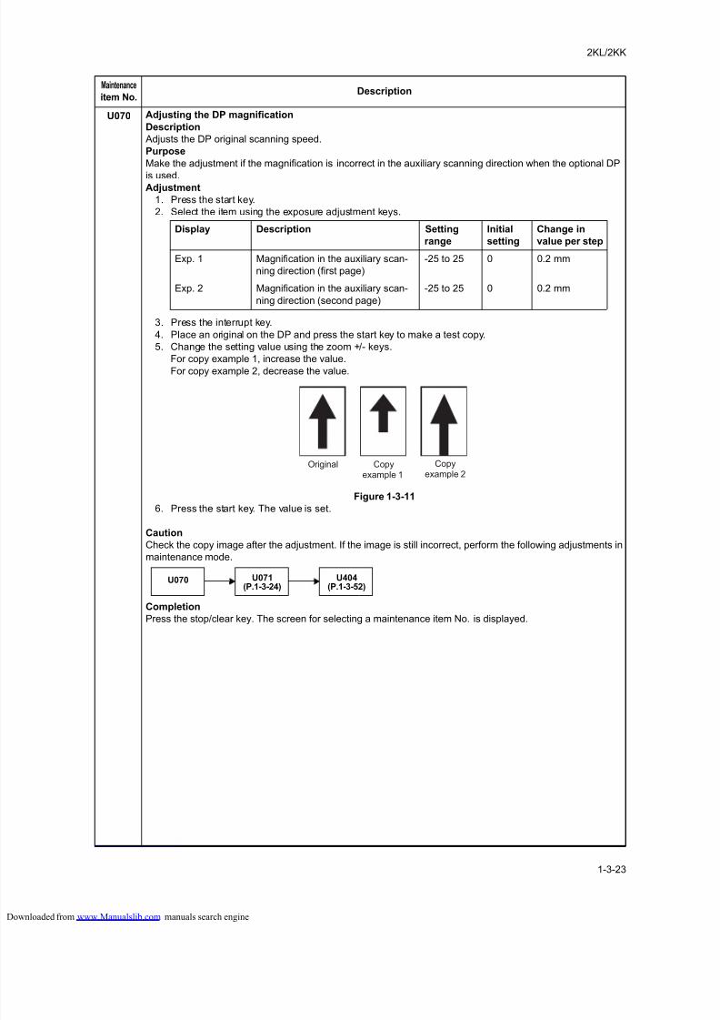
8/18/2019 taskalfa_220
http://slidepdf.com/reader/full/taskalfa220 61/300
2KL/2KK
1-3-23
U070 Adjusting the DP magnification
Description
Adjusts the DP original scanning speed.
Purpose
Make the adjustment if the magnification is incorrect in the auxiliary scanning direction when the optional DP
is used.Adjustment
1. Press the start key.
2. Select the item using the exposure adjustment keys.
3. Press the interrupt key.
4. Place an original on the DP and press the start key to make a test copy.
5. Change the setting value using the zoom +/- keys.
For copy example 1, increase the value.For copy example 2, decrease the value.
Figure 1-3-11
6. Press the start key. The value is set.
CautionCheck the copy image after the adjustment. If the image is still incorrect, perform the following adjustments in
maintenance mode.
Completion
Press the stop/clear key. The screen for selecting a maintenance item No. is displayed.
Maintenance
item No.Description
Display Description Setting
range
Initial
setting
Change in
value per step
Exp. 1 Magnification in the auxiliary scan-
ning direction (first page)
-25 to 25 0 0.2 mm
Exp. 2 Magnification in the auxiliary scan-
ning direction (second page)
-25 to 25 0 0.2 mm
Original Copyexample 1
Copyexample 2
U070 U071(P.1-3-24)
U404(P.1-3-52)
loaded from www.Manualslib.com manuals search engine
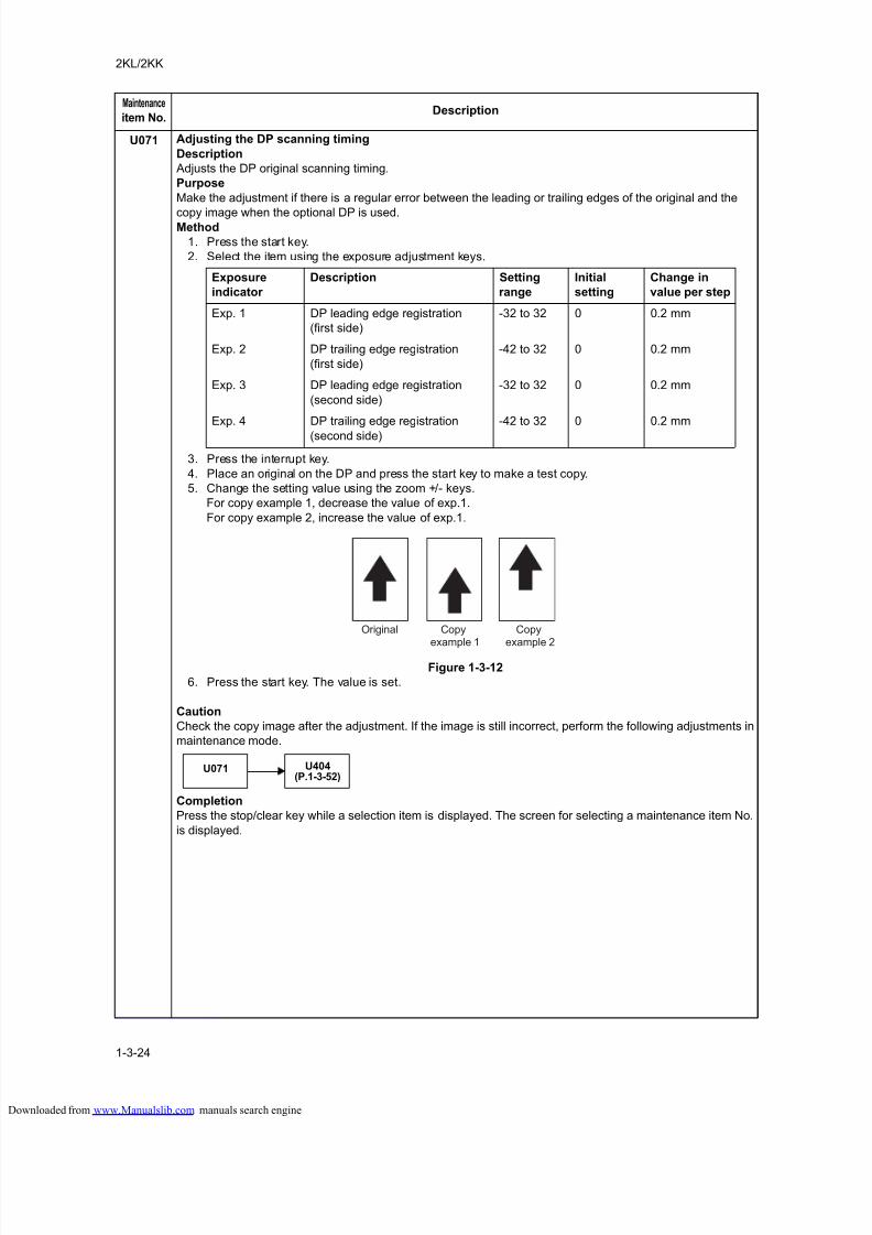
8/18/2019 taskalfa_220
http://slidepdf.com/reader/full/taskalfa220 62/300
2KL/2KK
1-3-24
U071 Adjusting the DP scanning timing
Description
Adjusts the DP original scanning timing.
Purpose
Make the adjustment if there is a regular error between the leading or trailing edges of the original and the
copy image when the optional DP is used.Method
1. Press the start key.
2. Select the item using the exposure adjustment keys.
3. Press the interrupt key.
4. Place an original on the DP and press the start key to make a test copy.
5. Change the setting value using the zoom +/- keys.
For copy example 1, decrease the value of exp.1.
For copy example 2, increase the value of exp.1.
Figure 1-3-12
6. Press the start key. The value is set.
Caution
Check the copy image after the adjustment. If the image is still incorrect, perform the following adjustments in
maintenance mode.
Completion
Press the stop/clear key while a selection item is displayed. The screen for selecting a maintenance item No.
is displayed.
Maintenance
item No.Description
Exposure
indicator
Description Setting
range
Initial
setting
Change in
value per step
Exp. 1 DP leading edge registration
(first side)
-32 to 32 0 0.2 mm
Exp. 2 DP trailing edge registration
(first side)
-42 to 32 0 0.2 mm
Exp. 3 DP leading edge registration
(second side)
-32 to 32 0 0.2 mm
Exp. 4 DP trailing edge registration
(second side)
-42 to 32 0 0.2 mm
Original Copyexample 1
Copyexample 2
U071 U404(P.1-3-52)
loaded from www.Manualslib.com manuals search engine
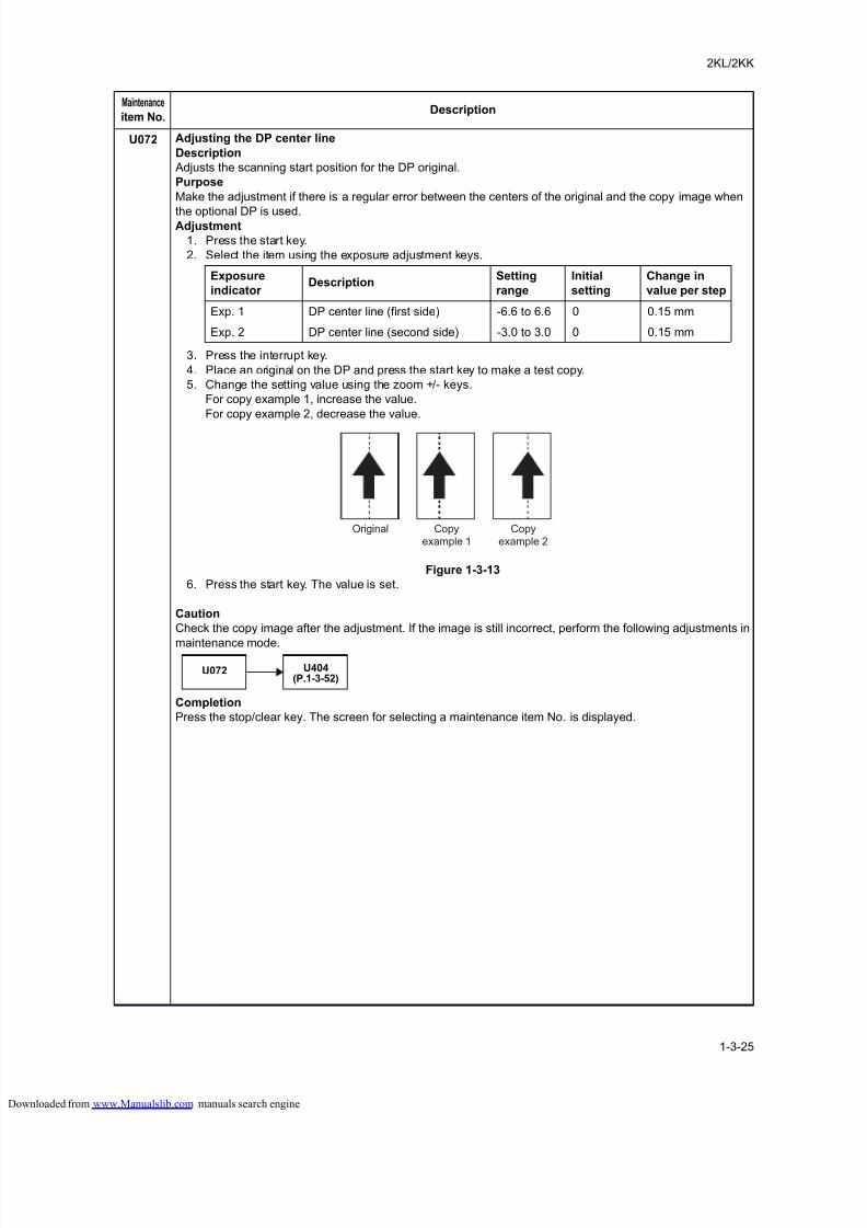
8/18/2019 taskalfa_220
http://slidepdf.com/reader/full/taskalfa220 63/300
2KL/2KK
1-3-25
U072 Adjusting the DP center line
Description
Adjusts the scanning start position for the DP original.
Purpose
Make the adjustment if there is a regular error between the centers of the original and the copy image when
the optional DP is used.Adjustment
1. Press the start key.
2. Select the item using the exposure adjustment keys.
3. Press the interrupt key.
4. Place an original on the DP and press the start key to make a test copy.
5. Change the setting value using the zoom +/- keys.
For copy example 1, increase the value.
For copy example 2, decrease the value.
Figure 1-3-13
6. Press the start key. The value is set.
Caution
Check the copy image after the adjustment. If the image is still incorrect, perform the following adjustments in
maintenance mode.
Completion
Press the stop/clear key. The screen for selecting a maintenance item No. is displayed.
Maintenance
item No.Description
Exposure
indicator Description
Setting
range
Initial
setting
Change in
value per step
Exp. 1 DP center line (first side) -6.6 to 6.6 0 0.15 mm
Exp. 2 DP center line (second side) -3.0 to 3.0 0 0.15 mm
Original Copyexample 1
Copyexample 2
U072 U404(P.1-3-52)
loaded from www.Manualslib.com manuals search engine
8/18/2019 taskalfa_220
http://slidepdf.com/reader/full/taskalfa220 64/300
2KL/2KK
1-3-26
U073 Checking scanner operation
Description
Simulates the scanner operation under arbitrary conditions.
Purpose
To check scanner operation.
Method1. Press the start key.
2. Select the item to be changed using the exposure adjustment keys.
3. Change the setting using the zoom +/- keys.
Paper size for each setting
4. Press the start key. The setting is set.
5. Press the interrupt key.
6. Press the start key. Scanning starts under the selected conditions.
7. To stop operation, press the stop/clear key.
Completion
Press the stop/clear key when scanning stops. The screen for selecting a maintenance item No. is displayed.
U074 Adjusting the DP input light luminosityDescription
Adjusts the luminosity of the exposure lamp for scanning originals from the DP.
Purpose
Used if the exposure amount differs significantly between when scanning an original on the platen and when
scanning an original from the DP.
Setting
1. Press the start key.
2. Change the setting using the zoom +/- keys.
Increasing the setting makes the luminosity higher, and decreasing it makes the luminosity lower.
3. Press the start key. The value is set.
Supplement
While this maintenance item is being executed, copying from an original is available in interrupt copying mode
(which is activated by pressing the interrupt key).
Completion
Press the stop/clear key. The screen for selecting a maintenance item No. is displayed.
Maintenance
item No.Description
Exposure indicator Operating conditions Setting range
Exp. 1 Magnification 25 to 400%
Exp. 2 Paper size See below.
Exp. 3 On and off of the exposure lamp on or off
Setting Paper size Setting Paper size
8 A4 42 A5R
9 B5 47 Folio24 11" x 8 1/2" 52 11" x 17"
36 A3 53 11" x 15"
39 B4 55 8 1/2" x 14"
40 A4R 56 8 1/2" x 11"
41 B5R 58 5 1/2" x 8 1/2"
Description Setting range Initial setting
DP input light luminosity 0 to 8 1
loaded from www.Manualslib.com manuals search engine
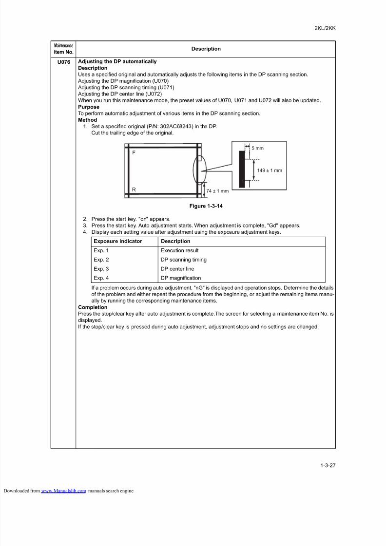
8/18/2019 taskalfa_220
http://slidepdf.com/reader/full/taskalfa220 65/300
2KL/2KK
1-3-27
U076 Adjusting the DP automatically
Description
Uses a specified original and automatically adjusts the following items in the DP scanning section.
Adjusting the DP magnification (U070)
Adjusting the DP scanning timing (U071)
Adjusting the DP center line (U072)When you run this maintenance mode, the preset values of U070, U071 and U072 will also be updated.
Purpose
To perform automatic adjustment of various items in the DP scanning section.
Method
1. Set a specified original (P/N: 302AC68243) in the DP.
Cut the trailing edge of the original.
Figure 1-3-14
2. Press the start key. "on" appears.
3. Press the start key. Auto adjustment starts. When adjustment is complete, "Gd" appears.
4. Display each setting value after adjustment using the exposure adjustment keys.
If a problem occurs during auto adjustment, "nG" is displayed and operation stops. Determine the detailsof the problem and either repeat the procedure from the beginning, or adjust the remaining items manu-
ally by running the corresponding maintenance items.
Completion
Press the stop/clear key after auto adjustment is complete.The screen for selecting a maintenance item No. is
displayed.
If the stop/clear key is pressed during auto adjustment, adjustment stops and no settings are changed.
Maintenance
item No.Description
F
R
5 mm
149 ± 1 mm
74 ± 1 mm
Exposure indicator Description
Exp. 1 Execution result
Exp. 2 DP scanning timing
Exp. 3 DP center line
Exp. 4 DP magnification
loaded from www.Manualslib.com manuals search engine
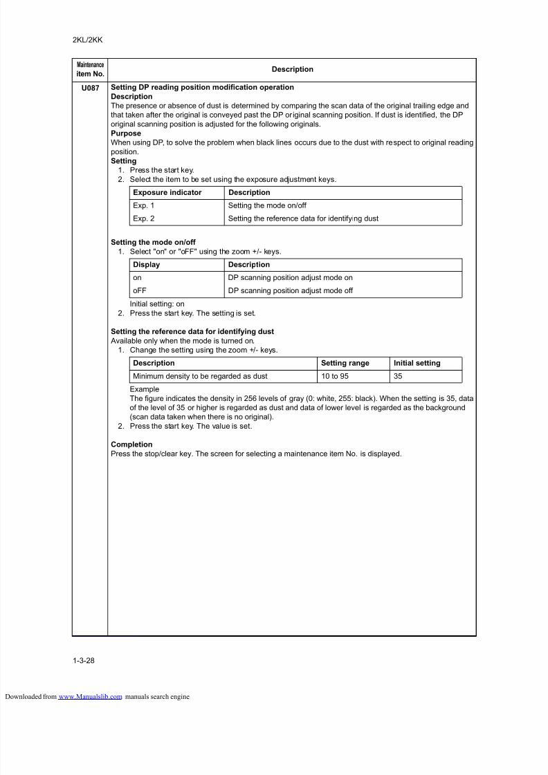
8/18/2019 taskalfa_220
http://slidepdf.com/reader/full/taskalfa220 66/300
2KL/2KK
1-3-28
U087 Setting DP reading position modification operation
Description
The presence or absence of dust is determined by comparing the scan data of the original trailing edge and
that taken after the original is conveyed past the DP or iginal scanning position. If dust is identified, the DP
original scanning position is adjusted for the following originals.
PurposeWhen using DP, to solve the problem when black lines occurs due to the dust with respect to original reading
position.
Setting
1. Press the start key.
2. Select the item to be set using the exposure adjustment keys.
Setting the mode on/off
1. Select "on" or "oFF" using the zoom +/- keys.
Initial setting: on
2. Press the start key. The setting is set.
Setting the reference data for identifying dust
Available only when the mode is turned on.
1. Change the setting using the zoom +/- keys.
Example
The figure indicates the density in 256 levels of gray (0: white, 255: black). When the setting is 35, data
of the level of 35 or higher is regarded as dust and data of lower level is regarded as the background(scan data taken when there is no original).
2. Press the start key. The value is set.
Completion
Press the stop/clear key. The screen for selecting a maintenance item No. is displayed.
Maintenance
item No.Description
Exposure indicator Description
Exp. 1 Setting the mode on/off
Exp. 2 Setting the reference data for identifying dust
Display Description
on DP scanning position adjust mode on
oFF DP scanning position adjust mode off
Description Setting range Initial setting
Minimum density to be regarded as dust 10 to 95 35
loaded from www.Manualslib.com manuals search engine
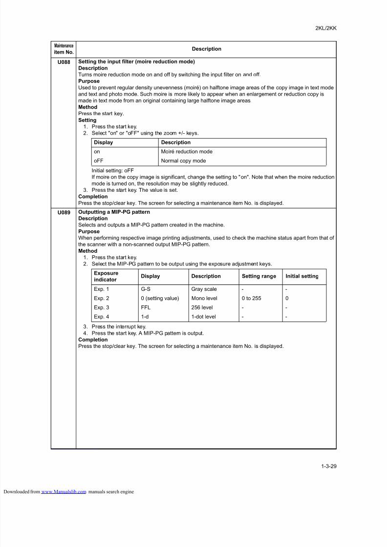
8/18/2019 taskalfa_220
http://slidepdf.com/reader/full/taskalfa220 67/300
2KL/2KK
1-3-29
U088 Setting the input filter (moire reduction mode)
Description
Turns moire reduction mode on and off by switching the input filter on and off.
Purpose
Used to prevent regular density unevenness (moiré) on halftone image areas of the copy image in text mode
and text and photo mode. Such moire is more likely to appear when an enlargement or reduction copy ismade in text mode from an original containing large halftone image areas.
Method
Press the start key.
Setting
1. Press the start key.
2. Select "on" or "oFF" using the zoom +/- keys.
Initial setting: oFF
If moire on the copy image is significant, change the setting to "on". Note that when the moire reduction
mode is turned on, the resolution may be slightly reduced.
3. Press the start key. The value is set.Completion
Press the stop/clear key. The screen for selecting a maintenance item No. is displayed.
U089 Outputting a MIP-PG pattern
Description
Selects and outputs a MIP-PG pattern created in the machine.
Purpose
When performing respective image printing adjustments, used to check the machine status apart from that of
the scanner with a non-scanned output MIP-PG pattern.
Method
1. Press the start key.
2. Select the MIP-PG pattern to be output using the exposure adjustment keys.
3. Press the interrupt key.
4. Press the start key. A MIP-PG pattern is output.
Completion
Press the stop/clear key. The screen for selecting a maintenance item No. is displayed.
Maintenance
item No.Description
Display Description
on Moiré reduction mode
oFF Normal copy mode
Exposure
indicator Display Description Setting range Initial setting
Exp. 1 G-S Gray scale - -
Exp. 2 0 (setting value) Mono level 0 to 255 0
Exp. 3 FFL 256 level - -
Exp. 4 1-d 1-dot level - -
loaded from www.Manualslib.com manuals search engine
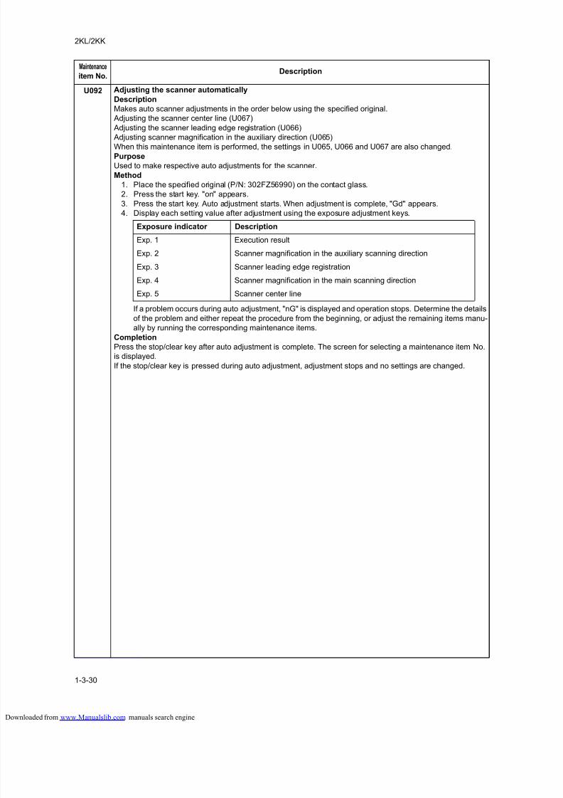
8/18/2019 taskalfa_220
http://slidepdf.com/reader/full/taskalfa220 68/300
2KL/2KK
1-3-30
U092 Adjusting the scanner automatically
Description
Makes auto scanner adjustments in the order below using the specified original.
Adjusting the scanner center line (U067)
Adjusting the scanner leading edge registration (U066)
Adjusting scanner magnification in the auxiliary direction (U065)When this maintenance item is performed, the settings in U065, U066 and U067 are also changed.
Purpose
Used to make respective auto adjustments for the scanner.
Method
1. Place the specified original (P/N: 302FZ56990) on the contact glass.
2. Press the start key. "on" appears.
3. Press the start key. Auto adjustment starts. When adjustment is complete, "Gd" appears.
4. Display each setting value after adjustment using the exposure adjustment keys.
If a problem occurs during auto adjustment, "nG" is displayed and operation stops. Determine the details
of the problem and either repeat the procedure from the beginning, or adjust the remaining items manu-
ally by running the corresponding maintenance items.
Completion
Press the stop/clear key after auto adjustment is complete. The screen for selecting a maintenance item No.
is displayed.
If the stop/clear key is pressed during auto adjustment, adjustment stops and no settings are changed.
Maintenance
item No.Description
Exposure indicator Description
Exp. 1 Execution result
Exp. 2 Scanner magnification in the auxiliary scanning direction
Exp. 3 Scanner leading edge registration
Exp. 4 Scanner magnification in the main scanning direction
Exp. 5 Scanner center line
loaded from www.Manualslib.com manuals search engine
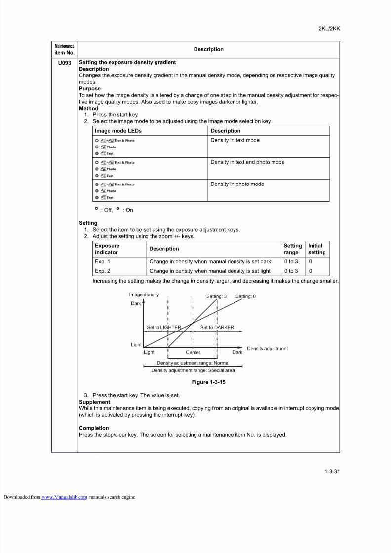
8/18/2019 taskalfa_220
http://slidepdf.com/reader/full/taskalfa220 69/300
2KL/2KK
1-3-31
U093 Setting the exposure density gradient
Description
Changes the exposure density gradient in the manual density mode, depending on respective image quality
modes.
Purpose
To set how the image density is altered by a change of one step in the manual density adjustment for respec-tive image quality modes. Also used to make copy images darker or lighter.
Method
1. Press the start key.
2. Select the image mode to be adjusted using the image mode selection key.
: Off, : On
Setting
1. Select the item to be set using the exposure adjustment keys.
2. Adjust the setting using the zoom +/- keys.
Increasing the setting makes the change in density larger, and decreasing it makes the change smaller.
Figure 1-3-15
3. Press the start key. The value is set.
Supplement
While this maintenance item is being executed, copying from an original is available in interrupt copying mode
(which is activated by pressing the interrupt key).
Completion
Press the stop/clear key. The screen for selecting a maintenance item No. is displayed.
Maintenance
item No.Description
Image mode LEDs Description
Density in text mode
Density in text and photo mode
Density in photo mode
Exposure
indicator Description
Setting
range
Initial
setting
Exp. 1 Change in density when manual density is set dark 0 to 3 0
Exp. 2 Change in density when manual density is set light 0 to 3 0
Image density
Density adjustment
Dark
Light
Light Center Dark
Density adjustment range: Special area
Setting: 0Setting: 3
Density adjustment range: Normal
Set to DARKERSet to LIGHTER
loaded from www.Manualslib.com manuals search engine
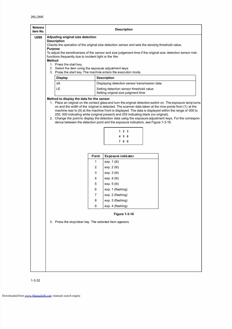
8/18/2019 taskalfa_220
http://slidepdf.com/reader/full/taskalfa220 70/300
2KL/2KK
1-3-32
U099 Adjusting original size detection
Description
Checks the operation of the original size detection sensor and sets the sensing threshold value.
Purpose
To adjust the sensitiveness of the sensor and size judgement time if the original size detection sensor mal-
functions frequently due to incident light or the like.Method
1. Press the start key.
2. Select the item using the exposure adjustment keys
3. Press the start key. The machine enters the execution mode.
Method to display the data for the sensor
1. Place an original on the contact glass and turn the original detection switch on. The exposure lamp turns
on and the width of the original is detected. The scanner data taken at the nine points from (1) at the
machine rear to (9) at the machine front is displayed. The data is displayed within the range of 000 to
255, 000 indicating white (original present) and 255 indicating black (no original).2. Change the point to display the detection data using the exposure adjustment keys. For the correspon-
dence between the detection point and the exposure indicators, see Figure 1-3-16.
Figure 1-3-16
3. Press the stop/clear key. The selected item appears.
Maintenance
item No.Description
Display Description
dA Displaying detection sensor transmission data
LE Setting detection sensor threshold value
Setting original size judgment time
1 2 3
4 5 6
7 8 9
Point Exposure indicator
1 exp. 1 (lit)
2 exp. 2 (lit)
3 exp. 3 (lit)
4 exp. 4 (lit)
5 exp. 5 (lit)
6 exp. 1 (flashing)
7 exp. 2 (flashing)
8 exp. 3 (flashing)
9 exp. 4 (flashing)
loaded from www.Manualslib.com manuals search engine
8/18/2019 taskalfa_220
http://slidepdf.com/reader/full/taskalfa220 71/300
2KL/2KK
1-3-33
U099
(cont.)
Method to set or check the original size detection threshold
1. Place an original on the contact glass and turn the original detection switch on. The original size detec-
tion starts and detection data is displayed.
2. Change the detection item using the exposure adjustment keys.
3. To change the original size detection threshold, light exp. 1, 2 or 3 and change the setting using the
zoom +/- keys.
4. Press the start key. The value is set.
5. Press the stop/clear key. The selected item appears.
Completion
Press the stop/clear key. The screen for selecting a maintenance item No. is displayed.
Maintenance
item No.Description
Exposure
indicator Description
Setting
range
Initial
setting
Exp. 1 Detection sensor threshold value 0 to 255 170
Exp. 2 Original size judgment time 0 to 100 ms 30
Exp. 3 Threshold value in the main scan direction for
A4R detection
220/240 mm 240
Exp. 4 Original size detection position display (mm) 0 to 350 mm -
Exp. 5 Detected original size display 0 to 63* -
loaded from www.Manualslib.com manuals search engine
8/18/2019 taskalfa_220
http://slidepdf.com/reader/full/taskalfa220 72/300
2KL/2KK
1-3-34
U100 Setting the main high voltage
Description
Changes the surface potential by changing the grid control voltage. Also performs main charging. Also
changes the setting of main charging copy quantity correction.
Purpose
To set the surface potential or check main charging. Also used when reentering data after initializing the setdata.
Start
1. Press the start key.
2. Select the item using the exposure adjustment keys.
Method for main charger output
1. Press the start key. The selected operation starts.
2. To stop operation, press the stop/clear key.
Setting the grid control voltage
1. Change the setting using the zoom +/- keys.
Increasing the setting makes the surface potential higher, and decreasing it makes the potential lower.
2. Press the start key. The value is set.
Setting the main charging copy quantity correction
1. Change the setting using the zoom +/- keys.
Copy interval: Sets the time interval from the previous copying. If the time from the previous copying
exceeds this preset value, the copy quantity counter will be reset.
Copy quantity: Sets the copy quantity from which copy quantity correction starts. When the copy quan-
tity counter reaches this preset value, correction will start.
Correction amount: Sets the correction amount for copy quantity correction.
Set the values in the range from 5 to 120 minutes for copy interval, from 10 to 2,000 sheets for copy
quantity, and from 5 to 50 bits for correction amount.
2. Press the start key. The value is set.
Supplement
While this maintenance item is being executed, copying from an original is available in interrupt copying mode
(which is activated by pressing the interrupt key).
Completion
Press the stop/clear key when main charger output stops while a selection item is displayed. The screen for
selecting a maintenance item No. is displayed.
Maintenance
item No.Description
Exposure indicator Description
Exp. 1 (lit) Changing the grid control voltage
Exp. 2 (lit) Turning the main charger on
Exp. 3 (lit) Turning the main charger on and the laser scanner unit on and off
Exp. 4 (lit) Main charging copy quantity correction, copy interval
Exp. 5 (lit) Main charging copy quantity correction, copy quantity
Exp. 1 (flashing) Main charging copy quantity correction, correction amount
Description Setting range Initial setting
Grid control voltage 0 to 255 107
Display Setting Setting range Initial setting
Exp. 4 (lit) Copy interval 1 to 255 (minute) 60
Exp. 5 (lit) Copy quantity 1 to 255 (10 sheets) 50
Exp. 1 (flashing) Correction amount 0 to 50 (bit) 10
loaded from www.Manualslib.com manuals search engine
8/18/2019 taskalfa_220
http://slidepdf.com/reader/full/taskalfa220 73/300
2KL/2KK
1-3-35
U101 Setting the other high voltages
Description
Changes the developing bias clock, the transfer and separation charging output timing.
Purpose
To check the developing bias clock, the transfer and separation charging output timing. Do not change the
preset value.Method
Press the start key.
Setting
1. Select the group to be set or checked using the image mode selection key.
2. Select the item to be set using the exposure adjustment keys.
: Off, : On
3. Change the setting using the zoom +/- keys.
4. Press the start key. The value is set.
SupplementWhile this maintenance item is being executed, copying from an original is available in interrupt copying mode
(which is activated by pressing the interrupt key).
Completion
Press the stop/clear key. The screen for selecting a maintenance item No. is displayed.
Maintenance
item No.Description
Image mode
LEDs
Exposure
indicator Description
Setting
range
Initial
setting
Exp. 1 (lit) Developing bias clock frequency (copier) 2 to 255 27
Exp. 2 (lit) Developing bias clock duty (copier) 1 to 99 45
Exp. 3 (lit) Developing bias clock frequency (printer) 2 to 255 22
Exp. 4 (lit) Developing bias clock duty (printer) 1 to 99 45
Exp. 5 (lit) Transfer control voltage (large size) 0 to 255 123
Exp. 1 (f lashing) Transfer control voltage (small size) 0 to 255 126
Exp. 2 (flashing) Transfer charging output OFF timing 0 to 255 33
Exp. 3 (flashing) Transfer charging output ON timing 0 to 255 31
Exp. 1 (lit) Separation control voltage 0 to 255 1
Exp. 2 (lit) Separation charging output ON timing 0 to 255 20
Exp. 3 (lit) Separation charging output OFF timing 0 to 255 42
Exp. 4 (lit) Separation control mode 0 to 3 2
loaded from www.Manualslib.com manuals search engine
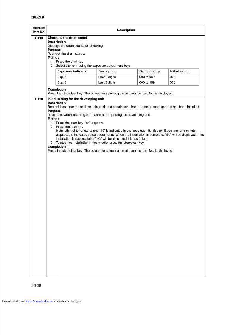
8/18/2019 taskalfa_220
http://slidepdf.com/reader/full/taskalfa220 74/300
2KL/2KK
1-3-36
U110 Checking the drum count
Description
Displays the drum counts for checking.
Purpose
To check the drum status.
Method1. Press the start key.
2. Select the item using the exposure adjustment keys.
Completion
Press the stop/clear key. The screen for selecting a maintenance item No. is displayed.
U130 Initial setting for the developing unit
Description
Replenishes toner to the developing unit to a certain level from the toner container that has been installed.
Purpose
To operate when installing the machine or replacing the developing unit.
Method
1. Press the start key. "on" appears.
2. Press the start key.
Installation of toner starts and "10" is indicated in the copy quantity display. Each time one minute
elapses, the indicated value decrements. When the installation is complete, "Gd" will be displayed if the
installation is successful or "nG" will be displayed if it has failed.
3. To stop the installation in the middle, press the stop/clear key.
Completion
Press the stop/clear key. The screen for selecting a maintenance item No. is displayed.
Maintenance
item No.Description
Exposure indicator Description Setting range Initial setting
Exp. 1 First 3 digits 000 to 999 000
Exp. 2 Last 3 digits 000 to 999 000
loaded from www.Manualslib.com manuals search engine
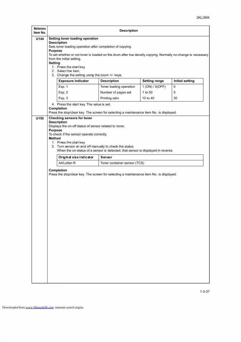
8/18/2019 taskalfa_220
http://slidepdf.com/reader/full/taskalfa220 75/300
2KL/2KK
1-3-37
U144 Setting toner loading operation
Description
Sets toner loading operation after completion of copying.
Purpose
To set whether or not toner is loaded on the drum after low density copying. Normally no change is necessary
from the initial setting.Setting
1. Press the start key.
2. Select the item.
3. Change the setting using the zoom +/- keys.
4. Press the start key. The value is set.
Completion
Press the stop/clear key. The screen for selecting a maintenance item No. is displayed.
U150Checking sensors for toner
Description
Displays the on-off status of sensor related to toner.
Purpose
To check if the sensor operate correctly.
Method
1. Press the start key.
2. Turn sensor on and off manually to check the status.
When the on-status of a sensor is detected, that sensor is displayed in reverse.
Completion
Press the stop/clear key. The screen for selecting a maintenance item No. is displayed.
Maintenance
item No.Description
Exposure indicator Description Setting range Initial setting
Exp. 1 Toner loading operation 1 (ON) / 0(OFF) 0
Exp. 2 Number of pages set 1 to 50 5
Exp. 3 Printing ratio 10 to 40 30
Original size indicator Sensor
A4/Letter-R Toner container sensor (TCS)
loaded from www.Manualslib.com manuals search engine
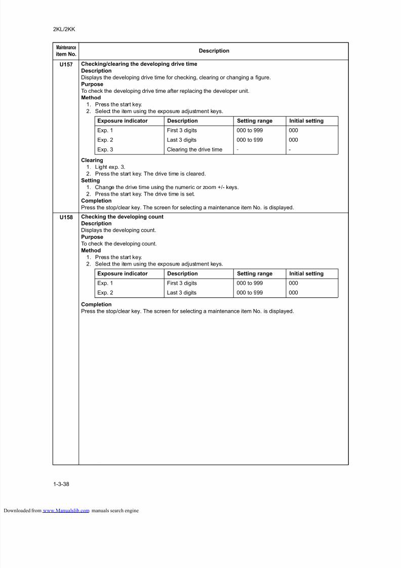
8/18/2019 taskalfa_220
http://slidepdf.com/reader/full/taskalfa220 76/300
2KL/2KK
1-3-38
U157 Checking/clearing the developing drive time
Description
Displays the developing drive time for checking, clearing or changing a figure.
Purpose
To check the developing drive time after replacing the developer unit.
Method1. Press the start key.
2. Select the item using the exposure adjustment keys.
Clearing
1. Light exp. 3.
2. Press the start key. The drive time is cleared.
Setting
1. Change the drive time using the numeric or zoom +/- keys.
2. Press the start key. The drive time is set.
CompletionPress the stop/clear key. The screen for selecting a maintenance item No. is displayed.
U158 Checking the developing count
Description
Displays the developing count.
Purpose
To check the developing count.
Method
1. Press the start key.
2. Select the item using the exposure adjustment keys.
Completion
Press the stop/clear key. The screen for selecting a maintenance item No. is displayed.
Maintenance
item No.Description
Exposure indicator Description Setting range Initial setting
Exp. 1 First 3 digits 000 to 999 000
Exp. 2 Last 3 digits 000 to 999 000
Exp. 3 Clearing the drive time - -
Exposure indicator Description Setting range Initial setting
Exp. 1 First 3 digits 000 to 999 000
Exp. 2 Last 3 digits 000 to 999 000
loaded from www.Manualslib.com manuals search engine
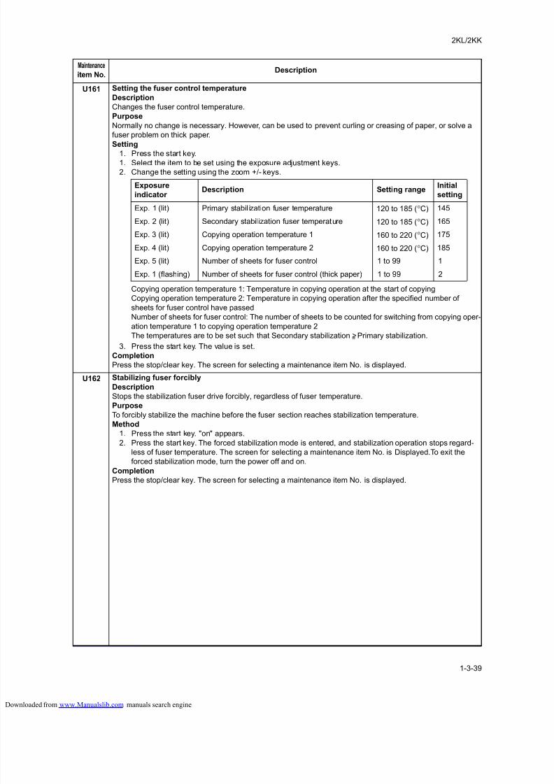
8/18/2019 taskalfa_220
http://slidepdf.com/reader/full/taskalfa220 77/300
2KL/2KK
1-3-39
U161 Setting the fuser control temperature
Description
Changes the fuser control temperature.
Purpose
Normally no change is necessary. However, can be used to prevent curling or creasing of paper, or solve a
fuser problem on thick paper.Setting
1. Press the start key.
1. Select the item to be set using the exposure adjustment keys.
2. Change the setting using the zoom +/- keys.
Copying operation temperature 1: Temperature in copying operation at the start of copying
Copying operation temperature 2: Temperature in copying operation after the specified number of
sheets for fuser control have passed
Number of sheets for fuser control: The number of sheets to be counted for switching from copying oper-
ation temperature 1 to copying operation temperature 2
The temperatures are to be set such that Secondary stabilization >= Primary stabilization.
3. Press the start key. The value is set.
Completion
Press the stop/clear key. The screen for selecting a maintenance item No. is displayed.
U162 Stabilizing fuser forcibly
Description
Stops the stabilization fuser drive forcibly, regardless of fuser temperature.
Purpose
To forcibly stabilize the machine before the fuser section reaches stabilization temperature.
Method
1. Press the start key. "on" appears.
2. Press the start key. The forced stabilization mode is entered, and stabilization operation stops regard-
less of fuser temperature. The screen for selecting a maintenance item No. is Displayed.To exit the
forced stabilization mode, turn the power off and on.
Completion
Press the stop/clear key. The screen for selecting a maintenance item No. is displayed.
Maintenance
item No.Description
Exposure
indicator Description Setting range
Initial
setting
Exp. 1 (lit) Primary stabil ization fuser temperature 120 to 185 (°C) 145
Exp. 2 (lit) Secondary stabilization fuser temperature 120 to 185 (°C) 165
Exp. 3 (lit) Copying operation temperature 1 160 to 220 (°C) 175
Exp. 4 (lit) Copying operation temperature 2 160 to 220 (°C) 185
Exp. 5 (lit) Number of sheets for fuser control 1 to 99 1
Exp. 1 (flashing) Number of sheets for fuser control (thick paper) 1 to 99 2
loaded from www.Manualslib.com manuals search engine
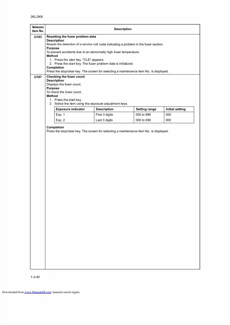
8/18/2019 taskalfa_220
http://slidepdf.com/reader/full/taskalfa220 78/300
2KL/2KK
1-3-40
U163 Resetting the fuser problem data
Description
Resets the detection of a service call code indicating a problem in the fuser section.
Purpose
To prevent accidents due to an abnormally high fuser temperature.
Method1. Press the start key. "CLE" appears.
2. Press the start key. The fuser problem data is initialized.
Completion
Press the stop/clear key. The screen for selecting a maintenance item No. is displayed.
U167 Checking the fuser count
Description
Displays the fuser count.
Purpose
To check the fuser count.
Method
1. Press the start key.
2. Select the item using the exposure adjustment keys.
Completion
Press the stop/clear key. The screen for selecting a maintenance item No. is displayed.
Maintenance
item No.Description
Exposure indicator Description Setting range Initial setting
Exp. 1 First 3 digits 000 to 999 000
Exp. 2 Last 3 digits 000 to 999 000
loaded from www.Manualslib.com manuals search engine
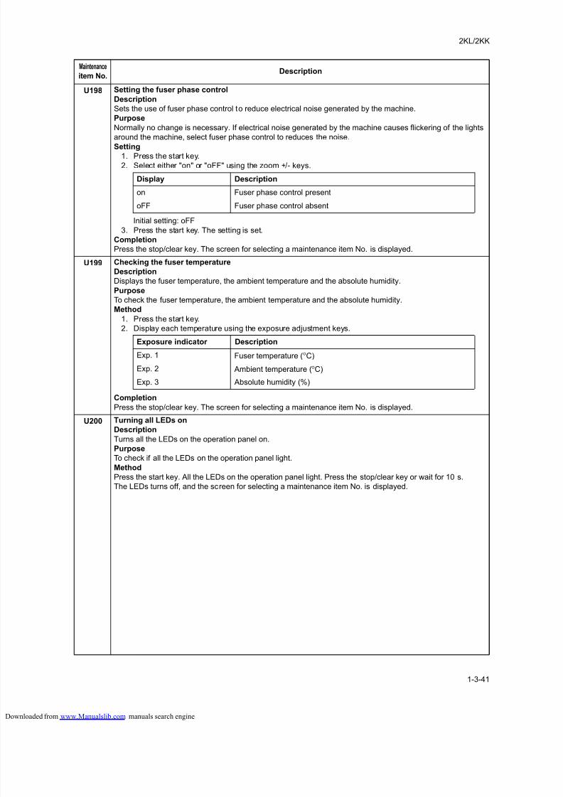
8/18/2019 taskalfa_220
http://slidepdf.com/reader/full/taskalfa220 79/300
2KL/2KK
1-3-41
U198 Setting the fuser phase control
Description
Sets the use of fuser phase control to reduce electrical noise generated by the machine.
Purpose
Normally no change is necessary. If electrical noise generated by the machine causes flickering of the lights
around the machine, select fuser phase control to reduces the noise.Setting
1. Press the start key.
2. Select either "on" or "oFF" using the zoom +/- keys.
Initial setting: oFF
3. Press the start key. The setting is set.
Completion
Press the stop/clear key. The screen for selecting a maintenance item No. is displayed.
U199 Checking the fuser temperature
Description
Displays the fuser temperature, the ambient temperature and the absolute humidity.Purpose
To check the fuser temperature, the ambient temperature and the absolute humidity.
Method
1. Press the start key.
2. Display each temperature using the exposure adjustment keys.
Completion
Press the stop/clear key. The screen for selecting a maintenance item No. is displayed.
U200 Turning all LEDs onDescription
Turns all the LEDs on the operation panel on.
Purpose
To check if all the LEDs on the operation panel light.
Method
Press the start key. All the LEDs on the operation panel light. Press the stop/clear key or wait for 10 s.
The LEDs turns off, and the screen for selecting a maintenance item No. is displayed.
Maintenance
item No.Description
Display Description
on Fuser phase control present
oFF Fuser phase control absent
Exposure indicator Description
Exp. 1 Fuser temperature (°C)
Exp. 2 Ambient temperature (°C)
Exp. 3 Absolute humidity (%)
loaded from www.Manualslib.com manuals search engine
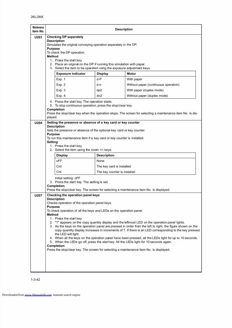
8/18/2019 taskalfa_220
http://slidepdf.com/reader/full/taskalfa220 80/300
2KL/2KK
1-3-42
U203 Checking DP separately
Description
Simulates the original conveying operation separately in the DP.
Purpose
To check the DP operation.
Method1. Press the start key.
2. Place an original on the DP if running this simulation with paper.
3. Select the item to be operated using the exposure adjustment keys.
4. Press the start key. The operation starts.
5. To stop continuous operation, press the stop/clear key.
Completion
Press the stop/clear key when the operation stops. The screen for selecting a maintenance item No. is dis-played.
U204 Setting the presence or absence of a key card or key counter
Description
Sets the presence or absence of the optional key card or key counter.
Purpose
To run this maintenance item if a key card or key counter is installed.
Setting
1. Press the start key.
2. Select the item using the zoom +/- keys.
Initial setting: oFF
3. Press the start key. The setting is set.
Completion
Press the stop/clear key. The screen for selecting a maintenance item No. is displayed.
U207 Checking the operation panel keys
Description
Checks operation of the operation panel keys.
Purpose
To check operation of all the keys and LEDs on the operation panel.
Method
1. Press the start key.
2. "1" appears on the copy quantity display and the leftmost LED on the operation panel lights.
3. As the keys on the operation panel are pressed in order from the left to right, the figure shown on the
copy quantity display increases in increments of 1. If there is an LED corresponding to the key pressed,the LED will light.
4. When all the keys on the operation panel have been pressed, all the LEDs light for up to 10 seconds.
5. When the LEDs go off, press the start key. All the LEDs light for 10 seconds again.
Completion
Press the stop/clear key. The screen for selecting a maintenance item No. is displayed.
Maintenance
item No.Description
Exposure indicator Display Motor
Exp. 1 d-P With paper
Exp. 2 d-n Without paper (continuous operation)
Exp. 3 dp2 With paper (duplex mode)
Exp. 4 dn2 Without paper (duplex mode)
Display Description
oFF None
Crd The key card is installed
Cnt The key counter is installed
loaded from www.Manualslib.com manuals search engine
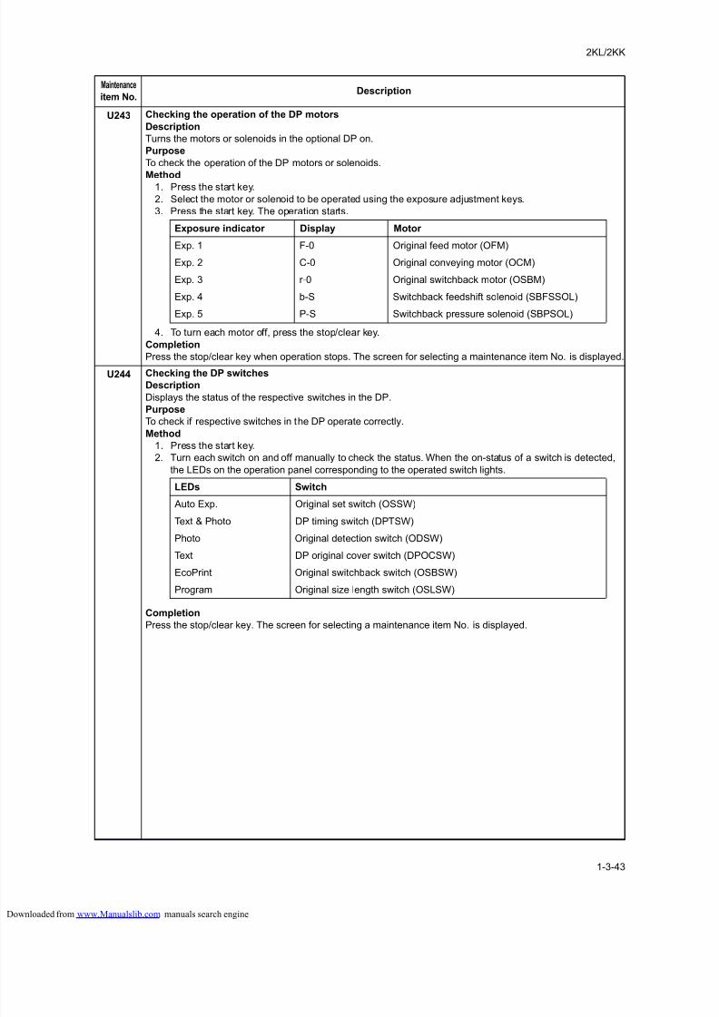
8/18/2019 taskalfa_220
http://slidepdf.com/reader/full/taskalfa220 81/300
2KL/2KK
1-3-43
U243 Checking the operation of the DP motors
Description
Turns the motors or solenoids in the optional DP on.
Purpose
To check the operation of the DP motors or solenoids.
Method1. Press the start key.
2. Select the motor or solenoid to be operated using the exposure adjustment keys.
3. Press the start key. The operation starts.
4. To turn each motor off, press the stop/clear key.
Completion
Press the stop/clear key when operation stops. The screen for selecting a maintenance item No. is displayed.
U244 Checking the DP switches
Description
Displays the status of the respective switches in the DP.
Purpose
To check if respective switches in the DP operate correctly.
Method
1. Press the start key.
2. Turn each switch on and off manually to check the status. When the on-status of a switch is detected,
the LEDs on the operation panel corresponding to the operated switch lights.
Completion
Press the stop/clear key. The screen for selecting a maintenance item No. is displayed.
Maintenance
item No.Description
Exposure indicator Display Motor
Exp. 1 F-0 Original feed motor (OFM)
Exp. 2 C-0 Original conveying motor (OCM)
Exp. 3 r-0 Original switchback motor (OSBM)
Exp. 4 b-S Switchback feedshift solenoid (SBFSSOL)
Exp. 5 P-S Switchback pressure solenoid (SBPSOL)
LEDs Switch
Auto Exp. Original set switch (OSSW)
Text & Photo DP timing switch (DPTSW)
Photo Original detection switch (ODSW)
Text DP original cover switch (DPOCSW)
EcoPrint Original switchback switch (OSBSW)
Program Original size length switch (OSLSW)
loaded from www.Manualslib.com manuals search engine
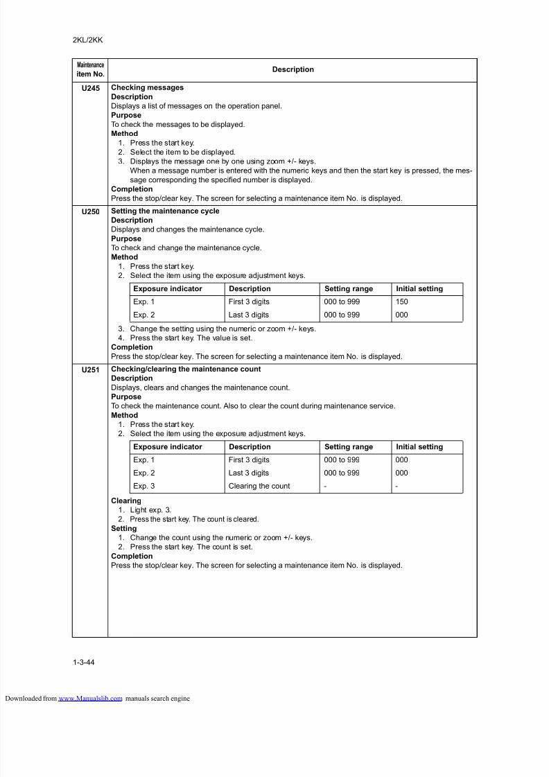
8/18/2019 taskalfa_220
http://slidepdf.com/reader/full/taskalfa220 82/300
2KL/2KK
1-3-44
U245 Checking messages
Description
Displays a list of messages on the operation panel.
Purpose
To check the messages to be displayed.
Method1. Press the start key.
2. Select the item to be displayed.
3. Displays the message one by one using zoom +/- keys.
When a message number is entered with the numeric keys and then the start key is pressed, the mes-
sage corresponding the specified number is displayed.
Completion
Press the stop/clear key. The screen for selecting a maintenance item No. is displayed.
U250 Setting the maintenance cycle
Description
Displays and changes the maintenance cycle.
Purpose
To check and change the maintenance cycle.
Method
1. Press the start key.
2. Select the item using the exposure adjustment keys.
3. Change the setting using the numeric or zoom +/- keys.
4. Press the start key. The value is set.
Completion
Press the stop/clear key. The screen for selecting a maintenance item No. is displayed.
U251 Checking/clearing the maintenance count
Description
Displays, clears and changes the maintenance count.
Purpose
To check the maintenance count. Also to clear the count during maintenance service.Method
1. Press the start key.
2. Select the item using the exposure adjustment keys.
Clearing
1. Light exp. 3.
2. Press the start key. The count is cleared.
Setting
1. Change the count using the numeric or zoom +/- keys.
2. Press the start key. The count is set.Completion
Press the stop/clear key. The screen for selecting a maintenance item No. is displayed.
Maintenance
item No.Description
Exposure indicator Description Setting range Initial setting
Exp. 1 First 3 digits 000 to 999 150
Exp. 2 Last 3 digits 000 to 999 000
Exposure indicator Description Setting range Initial setting
Exp. 1 First 3 digits 000 to 999 000
Exp. 2 Last 3 digits 000 to 999 000
Exp. 3 Clearing the count - -
loaded from www.Manualslib.com manuals search engine
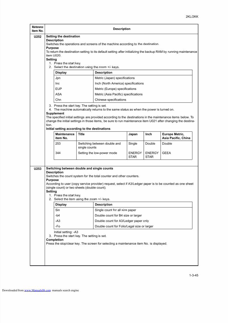
8/18/2019 taskalfa_220
http://slidepdf.com/reader/full/taskalfa220 83/300
2KL/2KK
1-3-45
U252 Setting the destination
Description
Switches the operations and screens of the machine according to the destination.
Purpose
To return the destination setting to its default setting after initializing the backup RAM by running maintenance
item U020.Setting
1. Press the start key.
2. Select the destination using the zoom +/- keys.
3. Press the start key. The setting is set.
4. The machine automatically returns to the same status as when the power is turned on.
SupplementThe specified initial settings are provided according to the destinations in the maintenance items below. To
change the initial settings in those items, be sure to run maintenance item U021 after changing the destina-
tion.
Initial setting according to the destinations
U253 Switching between double and single countsDescription
Switches the count system for the total counter and other counters.
Purpose
According to user (copy service provider) request, select if A3/Ledger paper is to be counted as one sheet
(single count) or two sheets (double count).
Setting
1. Press the start key.
2. Select the item using the zoom +/- keys.
Initial setting: -A3
3. Press the start key. The setting is set.
Completion
Press the stop/clear key. The screen for selecting a maintenance item No. is displayed.
Maintenance
item No.Description
Display Description
Jpn Metric (Japan) specifications
Inc Inch (North America) specifications
EUP Metric (Europe) specifications
ASA Metric (Asia Pacific) specifications
Chn Chinese specifications
Maintenance
item No.
Title Japan Inch Europe Metric,
Asia Pacific, China
253 Switching between double and
single counts
Single Double Double
344 Setting the low-power mode ENERGY
STAR
ENERGY
STAR
GEEA
Display Description
Sin Single count for all size paper
-b4 Double count for B4 size or larger
-A3 Double count for A3/Ledger paper only
-Fo Double count for Folio/Legal size or larger
loaded from www.Manualslib.com manuals search engine
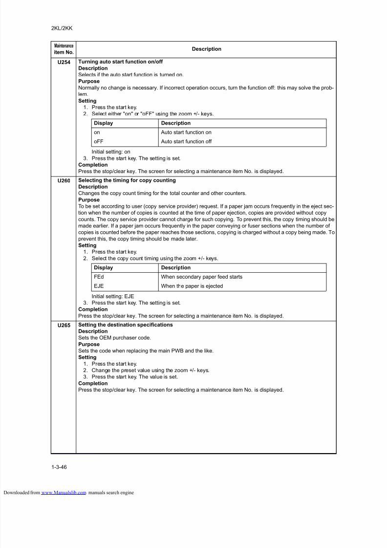
8/18/2019 taskalfa_220
http://slidepdf.com/reader/full/taskalfa220 84/300
2KL/2KK
1-3-46
U254 Turning auto start function on/off
Description
Selects if the auto start function is turned on.
Purpose
Normally no change is necessary. If incorrect operation occurs, turn the function off: this may solve the prob-
lem.Setting
1. Press the start key.
2. Select either "on" or "oFF" using the zoom +/- keys.
Initial setting: on
3. Press the start key. The setting is set.
Completion
Press the stop/clear key. The screen for selecting a maintenance item No. is displayed.
U260 Selecting the timing for copy counting
Description
Changes the copy count timing for the total counter and other counters.Purpose
To be set according to user (copy service provider) request. If a paper jam occurs frequently in the eject sec-
tion when the number of copies is counted at the time of paper ejection, copies are provided without copy
counts. The copy service provider cannot charge for such copying. To prevent this, the copy timing should be
made earlier. If a paper jam occurs frequently in the paper conveying or fuser sections when the number of
copies is counted before the paper reaches those sections, copying is charged without a copy being made. To
prevent this, the copy timing should be made later.
Setting
1. Press the start key.
2. Select the copy count timing using the zoom +/- keys.
Initial setting: EJE
3. Press the start key. The setting is set.
Completion
Press the stop/clear key. The screen for selecting a maintenance item No. is displayed.
U265 Setting the destination specifications
Description
Sets the OEM purchaser code.
Purpose
Sets the code when replacing the main PWB and the like.
Setting
1. Press the start key.
2. Change the preset value using the zoom +/- keys.
3. Press the start key. The value is set.
CompletionPress the stop/clear key. The screen for selecting a maintenance item No. is displayed.
Maintenance
item No.Description
Display Description
on Auto start function on
oFF Auto start function off
Display Description
FEd When secondary paper feed starts
EJE When the paper is ejected
loaded from www.Manualslib.com manuals search engine
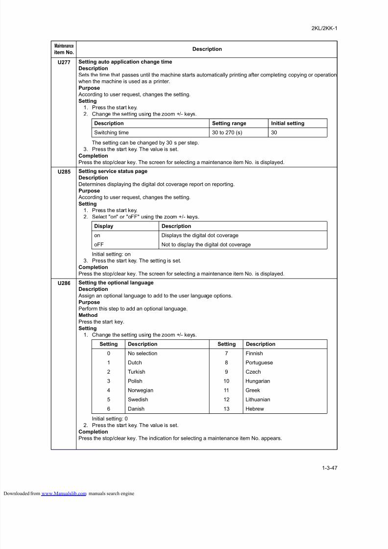
8/18/2019 taskalfa_220
http://slidepdf.com/reader/full/taskalfa220 85/300
2KL/2KK-1
1-3-47
U277 Setting auto application change time
Description
Sets the time that passes until the machine starts automatically printing after completing copying or operation
when the machine is used as a printer.
Purpose
According to user request, changes the setting.Setting
1. Press the start key.
2. Change the setting using the zoom +/- keys.
The setting can be changed by 30 s per step.
3. Press the start key. The value is set.
Completion
Press the stop/clear key. The screen for selecting a maintenance item No. is displayed.
U285 Setting service status page
Description
Determines displaying the digital dot coverage report on reporting.
Purpose According to user request, changes the setting.
Setting
1. Press the start key.
2. Select "on" or "oFF" using the zoom +/- keys.
Initial setting: on
3. Press the start key. The setting is set.
Completion
Press the stop/clear key. The screen for selecting a maintenance item No. is displayed.
U286 Setting the optional language
Description Assign an optional language to add to the user language options.
Purpose
Perform this step to add an optional language.
Method
Press the start key.
Setting
1. Change the setting using the zoom +/- keys.
Initial setting: 0
2. Press the start key. The value is set.
Completion
Press the stop/clear key. The indication for selecting a maintenance item No. appears.
Maintenance
item No.Description
Description Setting range Initial setting
Switching time 30 to 270 (s) 30
Display Description
on Displays the digital dot coverage
oFF Not to display the digital dot coverage
Setting Description Setting Description
0 No selection 7 Finnish
1 Dutch 8 Portuguese
2 Turkish 9 Czech
3 Polish 10 Hungarian
4 Norwegian 11 Greek
5 Swedish 12 Lithuanian
6 Danish 13 Hebrew
loaded from www.Manualslib.com manuals search engine
8/18/2019 taskalfa_220
http://slidepdf.com/reader/full/taskalfa220 86/300
2KL/2KK
1-3-48
U332 Setting the size conversion factor
Description
Sets the coefficient of nonstandard sizes in relation to the A4/Letter size. The coefficient set here is used to
convert the black ratio in relation to the A4/Letter size and to display the result in user simulation.
Purpose
To set the coefficient for converting the black ratio for nonstandard sizes in relation to the A4/Letter size forcopying and printing respectively.
Setting
1. Press the start key.
2. Change the setting using the zoom +/- keys.
3. Press the start key. The value is set.
Completion
Press the stop/clear key. The screen for selecting a maintenance item No. is displayed.
U341 Specific paper feed location setting for printing function
Description
Sets a paper feed location specified for printer output.
PurposeTo use a paper feed location only for printer output. A paper feed location specified for printer output cannot
be used for copy output.
Setting
1. Press the start key.
2. Select the paper feed location for the printer using the exposure adjustment keys.
3. Select "on" or "oFF" using the zoom +/- keys.
4. Press the start key. The setting is set.Completion
Press the stop/clear key. The screen for selecting a maintenance item No. is displayed.
U342 Setting the ejection restriction
Description
Sets or cancels the restriction on the number of sheets to be ejected continuously. When the restriction is set,
the number of sheets that can be ejected continuously will be limited to 250.
Purpose
According to user request, sets or cancels restriction on the number of sheets.
Setting
1. Press the start key.
2. Select "on" or "oFF" using the zoom +/- keys.
Initial setting: on
3. Press the start key. The setting is set.
Completion
Press the stop/clear key. The screen for selecting a maintenance item No. is displayed.
Maintenance
item No.Description
Description Setting range Initial setting
Size conversion factor 0.0 to 3.0 1.0
Display Description
Exp. 1 Cassette
Exp. 2 Optional first paper feeder
Exp. 3 Optional second paper feeder
Exp. 4 Optional third paper feeder
Display Description
on The number of sheets restricted.
oFF The number of sheets not restricted.
loaded from www.Manualslib.com manuals search engine
8/18/2019 taskalfa_220
http://slidepdf.com/reader/full/taskalfa220 87/300
2KL/2KK
1-3-49
U343 Switching between duplex/simplex copy mode
Description
Switches the Initial setting between duplex and simplex copy.
Purpose
To be set, according to frequency of use, to the more frequently used mode.
Setting1. Press the start key.
2. Select "on"or "oFF"using the zoom +/- keys.
Initial setting: Simplex copy
3. Press the start key. The setting is set.
Completion
Press the stop/clear key. The screen for selecting a maintenance item No. is displayed.
U344 Setting the low-power mode
DescriptionChanges the control for low-power mode.
Purpose According to user request, selects which has priority, the recovery time from low-power or energy saver.
Setting
1. Press the start key.
2. Change the setting using the zoom +/- keys.
Initial setting: ENERGY STAR
If GEEA is set, the Auto off mode setting is fixed to ON and cannot be changed. The maximum time for
entering the low power mode and the off mode becomes 120 minutes.
3. Press the start key. The setting is set.
Completion
Press the stop/clear key. The screen for selecting a maintenance item No. is displayed.
U345 Setting the value for maintenance due indication
DescriptionSets when to display a message notifying that the time for maintenance is about to be reached, by setting thenumber of copies that can be made before the current maintenance cycle ends.When the difference between the number of copies of the maintenance cycle and that of the maintenancecount reaches the set value, the message is displayed.Purpose
To change the time for maintenance due indication.
Setting
1. Press the start key.
2. Select the item using the exposure adjustment keys.
3. Change the setting using the zoom +/- keys.
4. Press the start key. The value is set.
Completion
Press the stop/clear key. The screen for selecting a maintenance item No. is displayed.
Maintenance
item No.Description
Display Description
on Duplex copy
oFF Simplex copy
Display Description
0 ENERGY STAR
1 GEEA
Exposure indicator Description Setting range Initial setting
Exp. 1 First 3 digits 000 to 999 000
Exp. 2 Last 3 digits 000 to 999 000
loaded from www.Manualslib.com manuals search engine
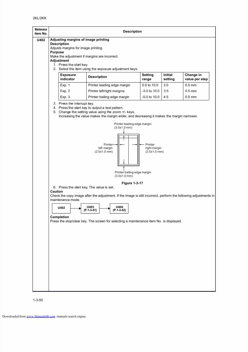
8/18/2019 taskalfa_220
http://slidepdf.com/reader/full/taskalfa220 88/300
2KL/2KK
1-3-50
U402 Adjusting margins of image printing
Description
Adjusts margins for image printing.
Purpose
Make the adjustment if margins are incorrect.
Adjustment1. Press the start key.
2. Select the item using the exposure adjustment keys.
3. Press the interrupt key.
4. Press the start key to output a test pattern.
5. Change the setting value using the zoom +/- keys.
Increasing the value makes the margin wider, and decreasing it makes the margin narrower.
Figure 1-3-17
6. Press the start key. The value is set.
Caution
Check the copy image after the adjustment. If the image is still incorrect, perform the following adjustments in
maintenance mode.
Completion
Press the stop/clear key. The screen for selecting a maintenance item No. is displayed.
Maintenance
item No.Description
Exposure
indicator Description
Setting
range
Initial
setting
Change in
value per step
Exp. 1 Printer leading edge margin 0.0 to 10.0 3.0 0.5 mm
Exp. 2 Printer left/right margins -3.0 to 10.0 3.5 0.5 mm
Exp. 3 Printer trailing edge margin -5.0 to 10.0 4.5 0.5 mm
Printer leading edge margin(3.0±1.0 mm)
Printer left margin
Printer right margin
Printer trailing edge margin(3.0±1.0 mm)
(2.5±1.0 mm) (2.5±1.0 mm)
U402 U403(P.1-3-51)
U404(P.1-3-52)
loaded from www.Manualslib.com manuals search engine
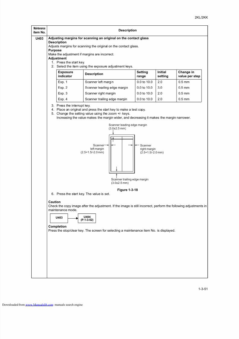
8/18/2019 taskalfa_220
http://slidepdf.com/reader/full/taskalfa220 89/300
2KL/2KK
1-3-51
U403 Adjusting margins for scanning an original on the contact glass
Description
Adjusts margins for scanning the original on the contact glass.
Purpose
Make the adjustment if margins are incorrect.
Adjustment1. Press the start key.
2. Select the item using the exposure adjustment keys.
3. Press the interrupt key.
4. Place an original and press the start key to make a test copy.
5. Change the setting value using the zoom +/- keys.
Increasing the value makes the margin wider, and decreasing it makes the margin narrower.
Figure 1-3-18
6. Press the start key. The value is set.
Caution
Check the copy image after the adjustment. If the image is still incorrect, perform the following adjustments in
maintenance mode.
Completion
Press the stop/clear key. The screen for selecting a maintenance item No. is displayed.
Maintenance
item No.Description
Exposure
indicator Description
Setting
range
Initial
setting
Change in
value per step
Exp. 1 Scanner left margin 0.0 to 10.0 2.0 0.5 mm
Exp. 2 Scanner leading edge margin 0.0 to 10.0 3.0 0.5 mm
Exp. 3 Scanner right margin 0.0 to 10.0 2.0 0.5 mm
Exp. 4 Scanner trailing edge margin 0.0 to 10.0 2.0 0.5 mm
Scanner leading edge margin(3.0±2.5 mm)
Scanner left margin
(2.5+1.5/-2.0 mm)
Scanner right margin(2.5+1.5/-2.0 mm)
Scanner trailing edge margin(3.0±2.5 mm)
U403 U404(P.1-3-52)
loaded from www.Manualslib.com manuals search engine
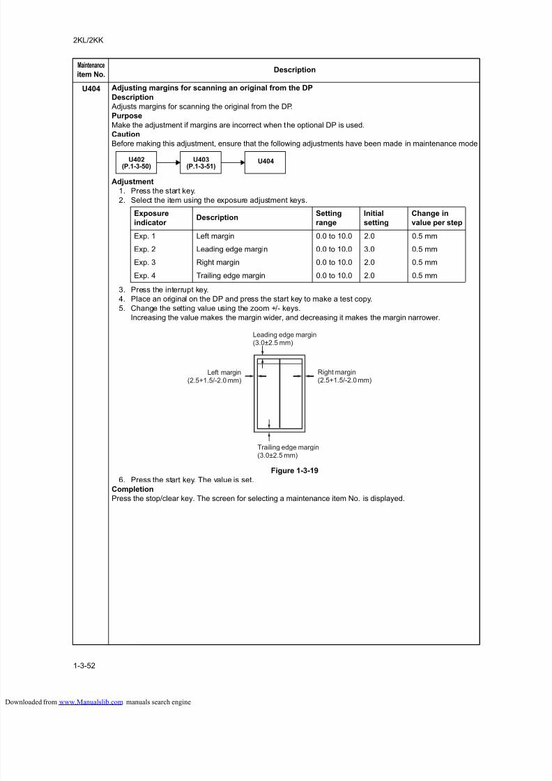
8/18/2019 taskalfa_220
http://slidepdf.com/reader/full/taskalfa220 90/300
2KL/2KK
1-3-52
U404 Adjusting margins for scanning an original from the DP
Description
Adjusts margins for scanning the original from the DP.
Purpose
Make the adjustment if margins are incorrect when the optional DP is used.
CautionBefore making this adjustment, ensure that the following adjustments have been made in maintenance mode
Adjustment
1. Press the start key.
2. Select the item using the exposure adjustment keys.
3. Press the interrupt key.
4. Place an original on the DP and press the start key to make a test copy.
5. Change the setting value using the zoom +/- keys.
Increasing the value makes the margin wider, and decreasing it makes the margin narrower.
Figure 1-3-19
6. Press the start key. The value is set.
Completion
Press the stop/clear key. The screen for selecting a maintenance item No. is displayed.
Maintenance
item No.Description
U403(P.1-3-51)
U402(P.1-3-50)
U404
Exposure
indicator Description
Setting
range
Initial
setting
Change in
value per step
Exp. 1 Left margin 0.0 to 10.0 2.0 0.5 mm
Exp. 2 Leading edge margin 0.0 to 10.0 3.0 0.5 mm
Exp. 3 Right margin 0.0 to 10.0 2.0 0.5 mm
Exp. 4 Trailing edge margin 0.0 to 10.0 2.0 0.5 mm
Leading edge margin(3.0±2.5 mm)
Trailing edge margin(3.0±2.5 mm)
Left margin(2.5+1.5/-2.0 mm)
Right margin(2.5+1.5/-2.0 mm)
loaded from www.Manualslib.com manuals search engine
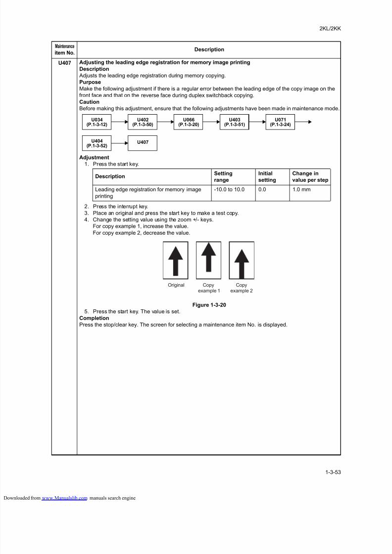
8/18/2019 taskalfa_220
http://slidepdf.com/reader/full/taskalfa220 91/300
2KL/2KK
1-3-53
U407 Adjusting the leading edge registration for memory image printing
Description
Adjusts the leading edge registration during memory copying.
Purpose
Make the following adjustment if there is a regular error between the leading edge of the copy image on the
front face and that on the reverse face during duplex switchback copying.Caution
Before making this adjustment, ensure that the following adjustments have been made in maintenance mode.
Adjustment
1. Press the start key.
2. Press the interrupt key.
3. Place an original and press the start key to make a test copy.
4. Change the setting value using the zoom +/- keys.
For copy example 1, increase the value.
For copy example 2, decrease the value.
Figure 1-3-20
5. Press the start key. The value is set.
Completion
Press the stop/clear key. The screen for selecting a maintenance item No. is displayed.
Maintenance
item No.Description
U402(P.1-3-50)
U034(P.1-3-12)
U066(P.1-3-20)
U403(P.1-3-51)
U071(P.1-3-24)
U407U404(P.1-3-52)
DescriptionSetting
range
Initial
setting
Change in
value per step
Leading edge registration for memory image
printing
-10.0 to 10.0 0.0 1.0 mm
Original Copy
example 1
Copy
example 2
loaded from www.Manualslib.com manuals search engine
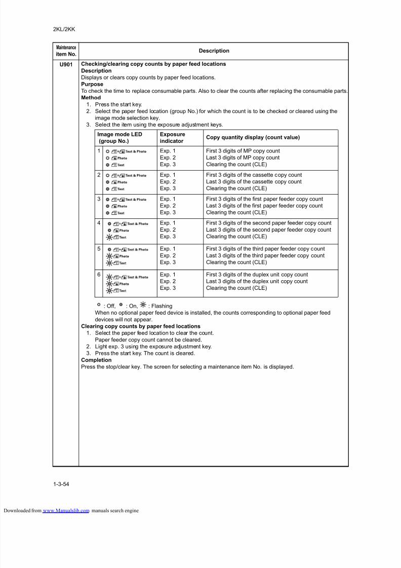
8/18/2019 taskalfa_220
http://slidepdf.com/reader/full/taskalfa220 92/300
2KL/2KK
1-3-54
U901 Checking/clearing copy counts by paper feed locations
Description
Displays or clears copy counts by paper feed locations.
Purpose
To check the time to replace consumable parts. Also to clear the counts after replacing the consumable parts.
Method1. Press the start key.
2. Select the paper feed location (group No.) for which the count is to be checked or cleared using the
image mode selection key.
3. Select the item using the exposure adjustment keys.
: Off, : On, : Flashing
When no optional paper feed device is installed, the counts corresponding to optional paper feed
devices will not appear.
Clearing copy counts by paper feed locations
1. Select the paper feed location to clear the count.
Paper feeder copy count cannot be cleared.
2. Light exp. 3 using the exposure adjustment key.
3. Press the start key. The count is cleared.
Completion
Press the stop/clear key. The screen for selecting a maintenance item No. is displayed.
Maintenance
item No.Description
Image mode LED
(group No.)
Exposure
indicator Copy quantity display (count value)
1 Exp. 1
Exp. 2
Exp. 3
First 3 digits of MP copy count
Last 3 digits of MP copy count
Clearing the count (CLE)
2 Exp. 1
Exp. 2
Exp. 3
First 3 digits of the cassette copy count
Last 3 digits of the cassette copy count
Clearing the count (CLE)
3 Exp. 1Exp. 2
Exp. 3
First 3 digits of the first paper feeder copy countLast 3 digits of the first paper feeder copy count
Clearing the count (CLE)
4 Exp. 1
Exp. 2
Exp. 3
First 3 digits of the second paper feeder copy count
Last 3 digits of the second paper feeder copy count
Clearing the count (CLE)
5 Exp. 1
Exp. 2
Exp. 3
First 3 digits of the third paper feeder copy count
Last 3 digits of the third paper feeder copy count
Clearing the count (CLE)
6 Exp. 1
Exp. 2
Exp. 3
First 3 digits of the duplex unit copy count
Last 3 digits of the duplex unit copy count
Clearing the count (CLE)
loaded from www.Manualslib.com manuals search engine
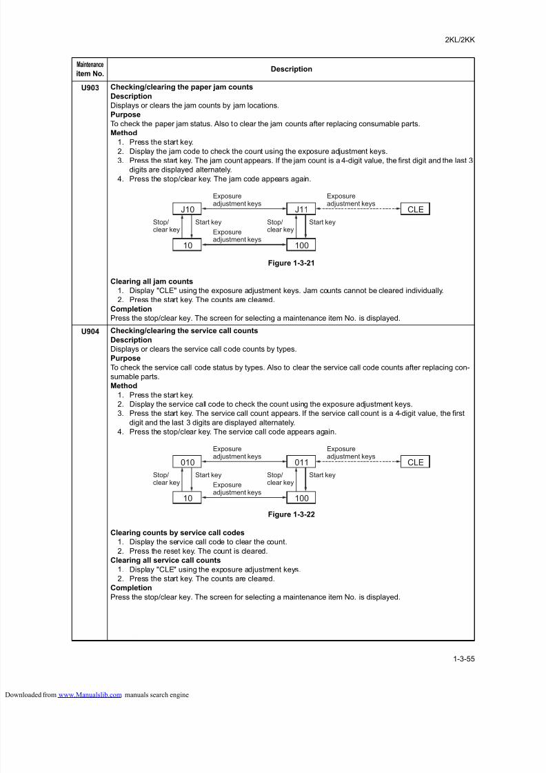
8/18/2019 taskalfa_220
http://slidepdf.com/reader/full/taskalfa220 93/300
2KL/2KK
1-3-55
U903 Checking/clearing the paper jam counts
Description
Displays or clears the jam counts by jam locations.
Purpose
To check the paper jam status. Also to clear the jam counts after replacing consumable parts.
Method1. Press the start key.
2. Display the jam code to check the count using the exposure adjustment keys.
3. Press the start key. The jam count appears. If the jam count is a 4-digit value, the first digit and the last 3
digits are displayed alternately.
4. Press the stop/clear key. The jam code appears again.
Figure 1-3-21
Clearing all jam counts
1. Display "CLE" using the exposure adjustment keys. Jam counts cannot be cleared individually.
2. Press the start key. The counts are cleared.
Completion
Press the stop/clear key. The screen for selecting a maintenance item No. is displayed.
U904 Checking/clearing the service call counts
Description
Displays or clears the service call code counts by types.
Purpose
To check the service call code status by types. Also to clear the service call code counts after replacing con-
sumable parts.
Method
1. Press the start key.
2. Display the service call code to check the count using the exposure adjustment keys.3. Press the start key. The service call count appears. If the service call count is a 4-digit value, the first
digit and the last 3 digits are displayed alternately.
4. Press the stop/clear key. The service call code appears again.
Figure 1-3-22
Clearing counts by service call codes
1. Display the service call code to clear the count.2. Press the reset key. The count is cleared.
Clearing all service call counts
1. Display "CLE" using the exposure adjustment keys.
2. Press the start key. The counts are cleared.
Completion
Press the stop/clear key. The screen for selecting a maintenance item No. is displayed.
Maintenance
item No.Description
Exposureadjustment keys
J10
10
Stop/clear key
Start key
J11
Exposureadjustment keys
CLE
100
Stop/clear key
Start key
Exposureadjustment keys
Exposureadjustment keys
010
10
Stop/clear key
Start key
011
Exposureadjustment keys
CLE
100
Stop/clear key
Start key
Exposureadjustment keys
loaded from www.Manualslib.com manuals search engine
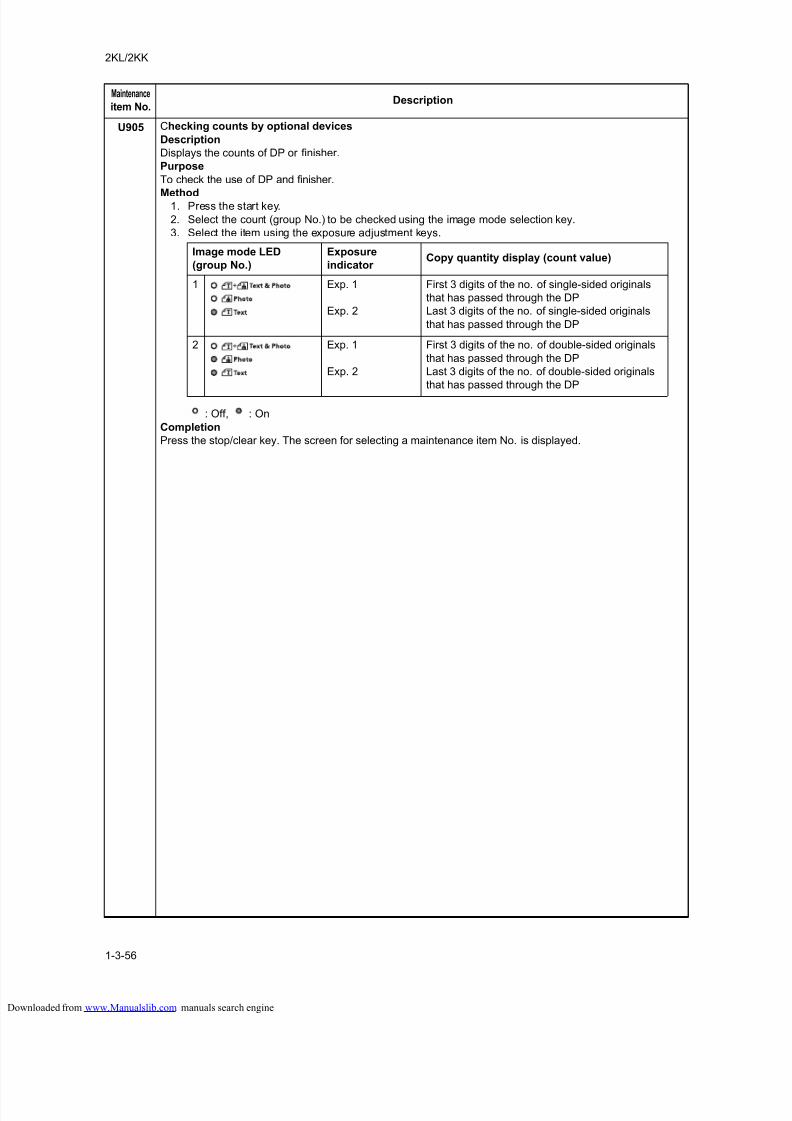
8/18/2019 taskalfa_220
http://slidepdf.com/reader/full/taskalfa220 94/300
2KL/2KK
1-3-56
U905 Checking counts by optional devices
Description
Displays the counts of DP or finisher.
Purpose
To check the use of DP and finisher.
Method1. Press the start key.
2. Select the count (group No.) to be checked using the image mode selection key.
3. Select the item using the exposure adjustment keys.
: Off, : On
Completion
Press the stop/clear key. The screen for selecting a maintenance item No. is displayed.
Maintenance
item No.Description
Image mode LED
(group No.)
Exposure
indicator Copy quantity display (count value)
1 Exp. 1
Exp. 2
First 3 digits of the no. of single-sided originals
that has passed through the DP
Last 3 digits of the no. of single-sided originals
that has passed through the DP
2 Exp. 1
Exp. 2
First 3 digits of the no. of double-sided originals
that has passed through the DP
Last 3 digits of the no. of double-sided originals
that has passed through the DP
loaded from www.Manualslib.com manuals search engine
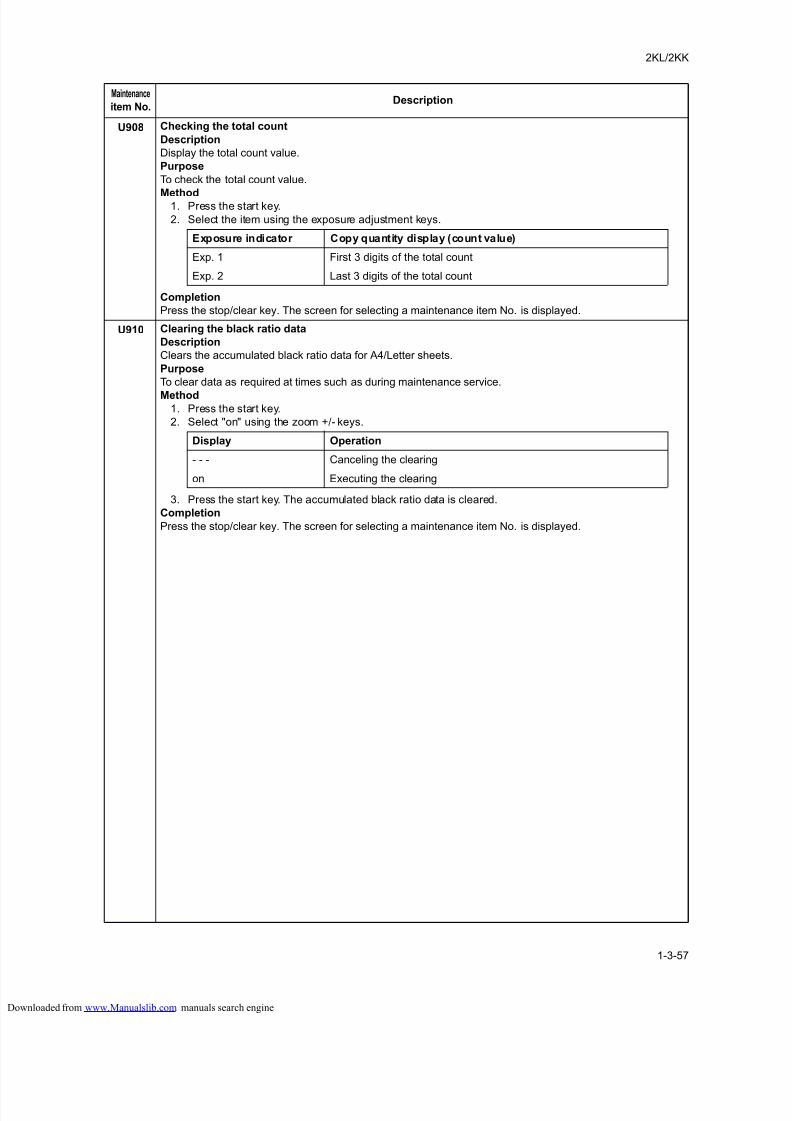
8/18/2019 taskalfa_220
http://slidepdf.com/reader/full/taskalfa220 95/300
2KL/2KK
1-3-57
U908 Checking the total count
Description
Display the total count value.
Purpose
To check the total count value.
Method1. Press the start key.
2. Select the item using the exposure adjustment keys.
Completion
Press the stop/clear key. The screen for selecting a maintenance item No. is displayed.
U910 Clearing the black ratio data
Description
Clears the accumulated black ratio data for A4/Letter sheets.
Purpose
To clear data as required at times such as during maintenance service.
Method1. Press the start key.
2. Select "on" using the zoom +/- keys.
3. Press the start key. The accumulated black ratio data is cleared.
Completion
Press the stop/clear key. The screen for selecting a maintenance item No. is displayed.
Maintenance
item No.Description
Exposure indicator Copy quantity display (count value)
Exp. 1 First 3 digits of the total count
Exp. 2 Last 3 digits of the total count
Display Operation
- - - Canceling the clearing
on Executing the clearing
loaded from www.Manualslib.com manuals search engine
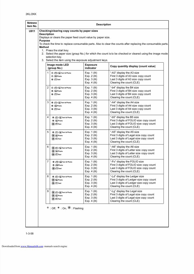
8/18/2019 taskalfa_220
http://slidepdf.com/reader/full/taskalfa220 96/300
2KL/2KK
1-3-58
U911 Checking/clearing copy counts by paper sizes
Description
Displays or clears the paper feed count value by paper size.
Purpose
To check the time to replace consumable parts. Also to clear the counts after replacing the consumable parts.
Method1. Press the start key.
2. Select the paper size (group No.) for which the count is to be checked or cleared using the image mode
selection key.
3. Select the item using the exposure adjustment keys.
: Off, : On, : Flashing
Maintenance
item No.Description
Image mode LED
(group No.)
Exposure
indicator Copy quantity display (count value)
1 Exp. 1 (lit)
Exp. 2 (lit)
Exp. 3 (lit)
Exp. 4 (lit)
“-A3” display the A3 size
First 3 digits of A3 size copy count
Last 3 digits of A3 size copy count
Clearing the count (CLE)
2 Exp. 1 (lit)
Exp. 2 (lit)
Exp. 3 (lit)
Exp. 4 (lit)
“-b4” display the B4 size
First 3 digits of B4 size copy count
Last 3 digits of B4 size copy count
Clearing the count (CLE)
3 Exp. 1 (lit)
Exp. 2 (lit)
Exp. 3 (lit)
Exp. 4 (lit)
“-A4” display the A4 size
First 3 digits of A4 size copy count
Last 3 digits of A4 size copy count
Clearing the count (CLE)
4 Exp. 1 (lit)
Exp. 2 (lit)
Exp. 3 (lit)
Exp. 4 (lit)
“-b5” display the B5 size
First 3 digits of FOLIO size copy count
Last 3 digits of FOLIO size copy count
Clearing the count (CLE)
5 Exp. 1 (lit)
Exp. 2 (lit)
Exp. 3 (lit)
Exp. 4 (lit)
“-A5” display the A5 size
First 3 digits of Legal size copy count
Last 3 digits of Legal size copy count
Clearing the count (CLE)
6 Exp. 1 (lit)
Exp. 2 (lit)
Exp. 3 (lit)
Exp. 4 (lit)
“-A6” display the A6 size
First 3 digits of Letter size copy count
Last 3 digits of Letter size copy count
Clearing the count (CLE)
7 Exp. 1 (lit)
Exp. 2 (lit)
Exp. 3 (lit)
Exp. 4 (lit)
“-Fo” display the FOLIO size
First 3 digits of FOLIO size copy count
Last 3 digits of FOLIO size copy count
Clearing the count (CLE)
8 Exp. 1 (lit)
Exp. 2 (lit)
Exp. 3 (lit)
Exp. 4 (lit)
“-Ld” display the Ledger size
First 3 digits of Ledger size copy count
Last 3 digits of Ledger size copy count
Clearing the count (CLE)
9 Exp. 1 (lit)Exp. 2 (lit)
Exp. 3 (lit)
Exp. 4 (lit)
“-Lg” display the Legal sizeFirst 3 digits of Legal size copy count
Last 3 digits of Legal size copy count
Clearing the count (CLE)
loaded from www.Manualslib.com manuals search engine
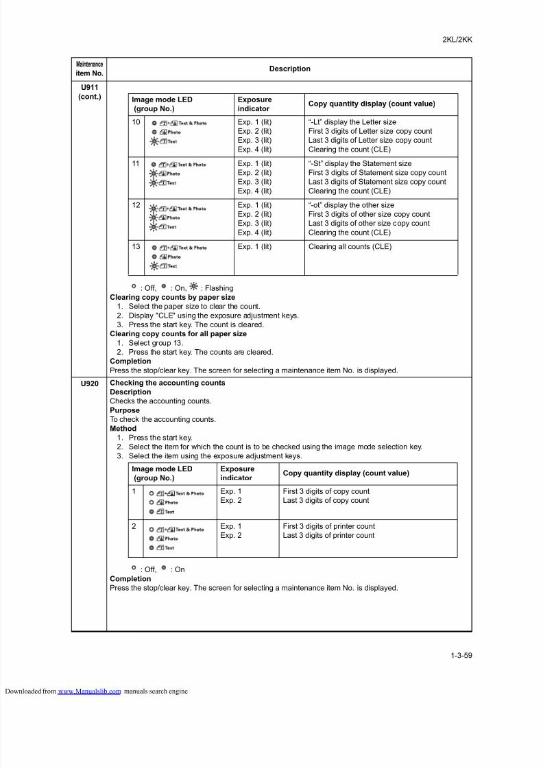
8/18/2019 taskalfa_220
http://slidepdf.com/reader/full/taskalfa220 97/300
2KL/2KK
1-3-59
U911
(cont.)
: Off, : On, : Flashing
Clearing copy counts by paper size
1. Select the paper size to clear the count.
2. Display "CLE" using the exposure adjustment keys.
3. Press the start key. The count is cleared.
Clearing copy counts for all paper size
1. Select group 13.
2. Press the start key. The counts are cleared.
Completion
Press the stop/clear key. The screen for selecting a maintenance item No. is displayed.
U920 Checking the accounting counts
Description
Checks the accounting counts.Purpose
To check the accounting counts.
Method
1. Press the start key.
2. Select the item for which the count is to be checked using the image mode selection key.
3. Select the item using the exposure adjustment keys.
: Off, : On
Completion
Press the stop/clear key. The screen for selecting a maintenance item No. is displayed.
Maintenance
item No.Description
Image mode LED
(group No.)
Exposure
indicator Copy quantity display (count value)
10 Exp. 1 (lit)
Exp. 2 (lit)Exp. 3 (lit)
Exp. 4 (lit)
“-Lt” display the Letter size
First 3 digits of Letter size copy countLast 3 digits of Letter size copy count
Clearing the count (CLE)
11 Exp. 1 (lit)
Exp. 2 (lit)
Exp. 3 (lit)
Exp. 4 (lit)
“-St” display the Statement size
First 3 digits of Statement size copy count
Last 3 digits of Statement size copy count
Clearing the count (CLE)
12 Exp. 1 (lit)
Exp. 2 (lit)
Exp. 3 (lit)
Exp. 4 (lit)
“-ot” display the other size
First 3 digits of other size copy count
Last 3 digits of other size copy count
Clearing the count (CLE)
13 Exp. 1 (lit) Clearing all counts (CLE)
Image mode LED
(group No.)
Exposure
indicator Copy quantity display (count value)
1 Exp. 1
Exp. 2
First 3 digits of copy count
Last 3 digits of copy count
2 Exp. 1
Exp. 2
First 3 digits of printer count
Last 3 digits of printer count
loaded from www.Manualslib.com manuals search engine
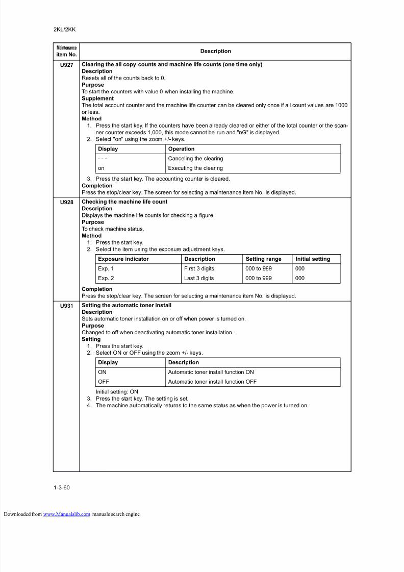
8/18/2019 taskalfa_220
http://slidepdf.com/reader/full/taskalfa220 98/300
2KL/2KK
1-3-60
U927 Clearing the all copy counts and machine life counts (one time only)
Description
Resets all of the counts back to 0.
Purpose
To start the counters with value 0 when installing the machine.
SupplementThe total account counter and the machine life counter can be cleared only once if all count values are 1000
or less.
Method
1. Press the start key. If the counters have been already cleared or either of the total counter or the scan-
ner counter exceeds 1,000, this mode cannot be run and "nG" is displayed.
2. Select "on" using the zoom +/- keys.
3. Press the start key. The accounting counter is cleared.
Completion
Press the stop/clear key. The screen for selecting a maintenance item No. is displayed.
U928 Checking the machine life countDescription
Displays the machine life counts for checking a figure.
Purpose
To check machine status.
Method
1. Press the start key.
2. Select the item using the exposure adjustment keys.
Completion
Press the stop/clear key. The screen for selecting a maintenance item No. is displayed.
U931 Setting the automatic toner install
Description
Sets automatic toner installation on or off when power is turned on.
Purpose
Changed to off when deactivating automatic toner installation.
Setting
1. Press the start key.
2. Select ON or OFF using the zoom +/- keys.
Initial setting: ON
3. Press the start key. The setting is set.4. The machine automatically returns to the same status as when the power is turned on.
Maintenance
item No.Description
Display Operation
- - - Canceling the clearing
on Executing the clearing
Exposure indicator Description Setting range Initial setting
Exp. 1 First 3 digits 000 to 999 000
Exp. 2 Last 3 digits 000 to 999 000
Display Description
ON Automatic toner install function ON
OFF Automatic toner install function OFF
loaded from www.Manualslib.com manuals search engine
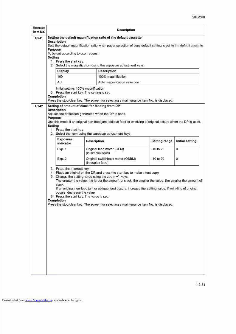
8/18/2019 taskalfa_220
http://slidepdf.com/reader/full/taskalfa220 99/300
2KL/2KK
1-3-61
U941 Setting the default magnification ratio of the default cassette
Description
Sets the default magnification ratio when paper selection of copy default setting is set to the default cassette.
Purpose
To be set according to user request.
Setting1. Press the start key.
2. Select the magnification using the exposure adjustment keys.
Initial setting: 100% magnification
3. Press the start key. The setting is set.
Completion
Press the stop/clear key. The screen for selecting a maintenance item No. is displayed.
U942 Setting of amount of slack for feeding from DP
Description
Adjusts the deflection generated when the DP is used.
PurposeUse this mode if an original non-feed jam, oblique feed or wrinkling of original occurs when the DP is used.
Setting
1. Press the start key.
2. Select the item using the exposure adjustment keys.
3. Press the interrupt key.
4. Place an original on the DP and press the start key to make a test copy.
5. Change the setting value using the zoom +/- keys.The greater the value, the larger the amount of slack; the smaller the value, the smaller the amount of
slack.
If an original non-feed jam or oblique feed occurs, increase the setting value. If wrinkling of original
occurs, decrease the value.
6. Press the start key. The value is set.
Completion
Press the stop/clear key. The screen for selecting a maintenance item No. is displayed.
Maintenance
item No.Description
Display Description
100 100% magnification
Aut Auto magnification selection
Exposure
indicator Description Setting range Initial setting
Exp. 1 Original feed motor (OFM)
(in simplex feed)
-10 to 20 0
Exp. 2 Original switchback motor (OSBM)
(in duplex feed)
-10 to 20 0
loaded from www.Manualslib.com manuals search engine
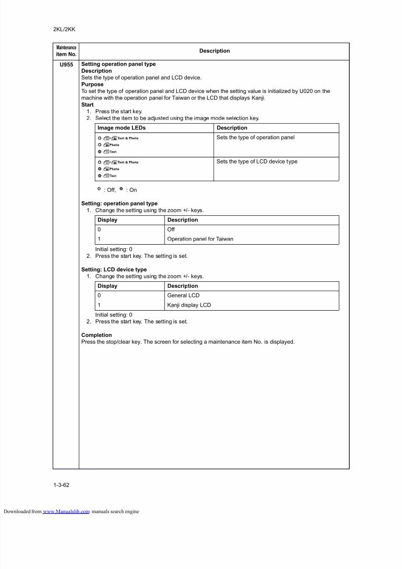
8/18/2019 taskalfa_220
http://slidepdf.com/reader/full/taskalfa220 100/300
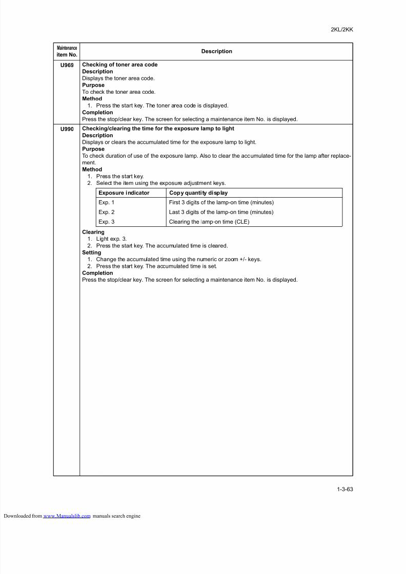
8/18/2019 taskalfa_220
http://slidepdf.com/reader/full/taskalfa220 101/300
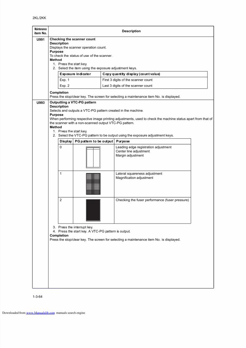
8/18/2019 taskalfa_220
http://slidepdf.com/reader/full/taskalfa220 102/300
2KL/2KK
1-3-64
U991 Checking the scanner count
Description
Displays the scanner operation count.
Purpose
To check the status of use of the scanner.
Method1. Press the start key.
2. Select the item using the exposure adjustment keys.
Completion
Press the stop/clear key. The screen for selecting a maintenance item No. is displayed.
U993 Outputting a VTC-PG pattern
Description
Selects and outputs a VTC-PG pattern created in the machine.
Purpose
When performing respective image printing adjustments, used to check the machine status apart from that of
the scanner with a non-scanned output VTC-PG pattern.Method
1. Press the start key.
2. Select the VTC-PG pattern to be output using the exposure adjustment keys.
3. Press the interrupt key.
4. Press the start key. A VTC-PG pattern is output.
Completion
Press the stop/clear key. The screen for selecting a maintenance item No. is displayed.
Maintenance
item No.Description
Exposure indicator Copy quantity display (count value)
Exp. 1 First 3 digits of the scanner count
Exp. 2 Last 3 digits of the scanner count
Display PG pattern to be output Purpose
0 Leading edge registration adjustment
Center line adjustment
Margin adjustment
1 Lateral squareness adjustment
Magnification adjustment
2 Checking the fuser performance (fuser pressure)
loaded from www.Manualslib.com manuals search engine
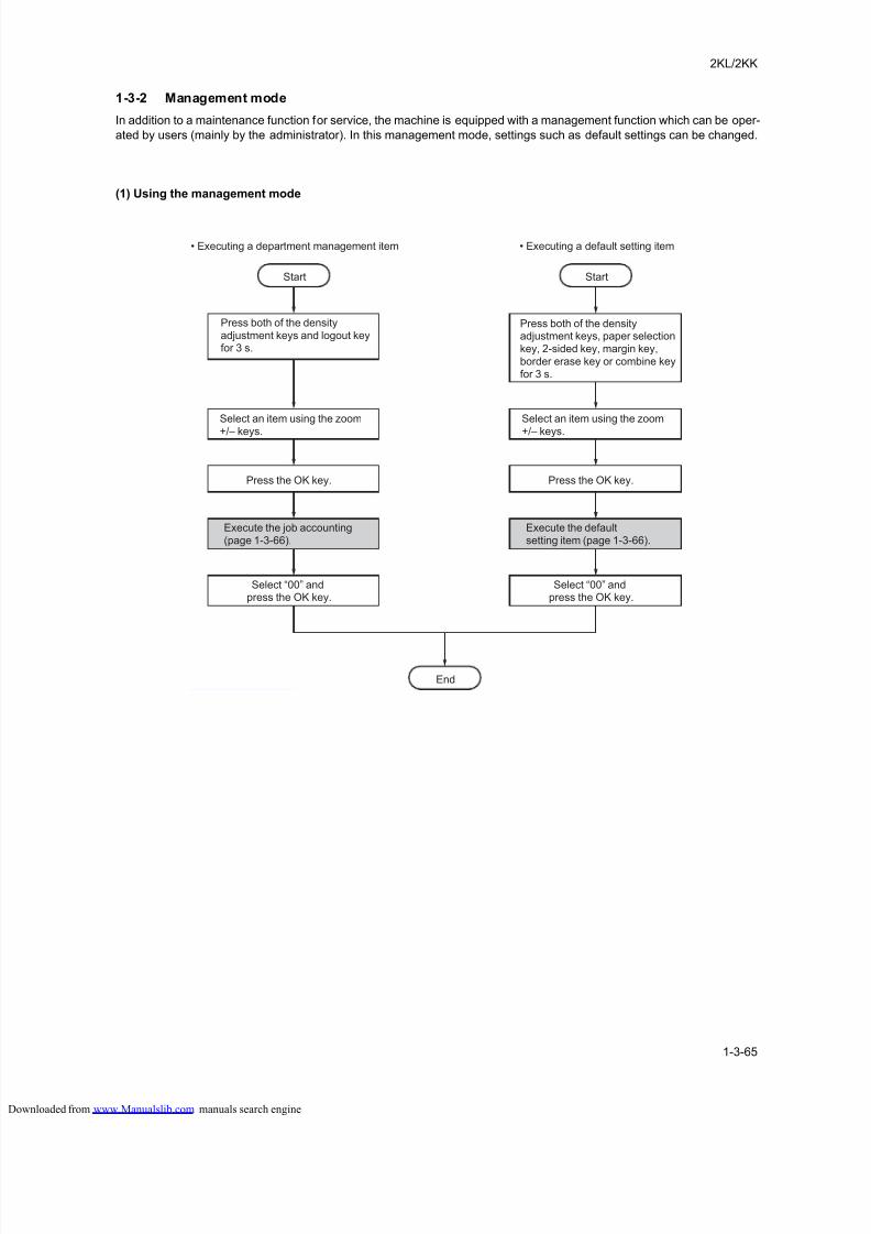
8/18/2019 taskalfa_220
http://slidepdf.com/reader/full/taskalfa220 103/300
8/18/2019 taskalfa_220
http://slidepdf.com/reader/full/taskalfa220 104/300
8/18/2019 taskalfa_220
http://slidepdf.com/reader/full/taskalfa220 105/300
2KL/2KK
1-3-67
Text + photo mode density adjustment
Adjusts the density to be used when text and photo
original is selected for the image mode.
1. Press both of the density adjustment keys for 3 s.
2. Select [08.Text+Ph Dens.] and press the OK key.
3. Select the setting and press the OK key.
Setting range: 1 (lightest) to 7 (darkest)
Photo density adjustment
Adjusts the density to be used when photo original is
selected for the image mode.
1. Press both of the density adjustment keys for 3 s.
2. Select [09.Photo Density] and press the OK key.
3. Select the setting and press the OK key.
Setting range: 1 (lightest) to 7 (darkest)
Text density adjustment
Adjusts the density to be used when text original is
selected for the image mode.
1. Press both of the density adjustment keys for 3 s.
2. Select [10.Text Density] and press the OK key.
3. Select the setting and press the OK key.Setting range: 1 (lightest) to 7 (darkest)
Processing to reduce black lines
Reduces black lines that may be caused when the DP
is used.
1. Press both of the density adjustment keys for 3 s.
2. Select [11.ReduceStreaks] and press the OK key.
3. Select [OFF], [Weak] or [Strong] and press the OK
key.
Photo processing
Select the image processing method for photo origi-
nals.
1. Press both of the density adjustment keys for 3 s.
2. Select [12.OptimezePhoto] and press the OK key.
3. Select [ErrorDiffusion] or [Dither Matrix] and press
the OK key.
Back ground adjustment
The ground color adjusting after copying.
1. Press both of the density adjustment keys for 3 s.
2. Select [13.OptimezBackgr] and press the OK key.
3. Select the setting and press the OK key.
Setting range: 1 (lightest) to 5 (darkest)
Cassette selection
Select the auto paper select function based on the orig-
inal size or priority cassette selection.
1. Press both of the density adjustment keys for 3 s.
2. Select [14.Initial Paper] and press the OK key.
3. Select [Auto] or [DefaultCassette] and press the OK
key.
Selecting paper types for automatic paper selection
Selects the cassette that is to be automatically be
given priority for use.
1. Press both of the density adjustment keys for 3 s.
2. Select [15.AutoSel Paper] and press the OK key.
3. Select the paper type and press the OK key.
Selected cassetteSelects the cassette that is to be automatically be
given priority for use.
1. Press both of the density adjustment keys for 3 s.
2. Select [16.DefaultCasset] and press the OK key.
3. Select [Cassette1], [Cassette2], [Cassette3] or
[Cassette4] and press the OK key.
Auto cassette switching
Sets whether the auto cassette switching function is
available.
1. Press both of the density adjustment keys for 3 s.
2. Select [17.AutoCassetSel] and press the OK key.
3. Select [Disting. paper] or [Not disting] and press the
OK key.This will be displayed when the optional paper
feeder is installed.
Auto sizing
Selects whether auto magnification selection or 100%
magnification is to be given priority when the sizes of
the original and copy paper are different.
1. Press both of the density adjustment keys for 3 s.
2. Select [18.PriorAutoZoom] and press the OK key.
3. Select [On] or [Off] and press the OK key.
Cassette paper size (cassette 1)
Sets the paper size for the cassette so that it will be
automatically selected.
1. Press paper selection keys for 3 s.
2. Select [19.Cassette1Size] and press the OK key.
3. Select the paper size and press the OK key.
Cassette paper size (cassette 2)
Sets the paper size for the first paper feeder so that it
will be automatically selected.
1. Press paper selection keys for 3 s.
2. Select [20.Cassette2Size] and press the OK key.
3. Select the paper size and press the OK key.
This will be displayed when the optional paper
feeder is installed.
Cassette paper size (cassette 3)
Sets the paper size for the second paper feeder so that
it will be automatically selected.
1. Press paper selection keys for 3 s.
2. Select [21.Cassette3Size] and press the OK key.
3. Select the paper size and press the OK key.
This will be displayed when the optional paper
feeder is installed.
loaded from www.Manualslib.com manuals search engine
8/18/2019 taskalfa_220
http://slidepdf.com/reader/full/taskalfa220 106/300
2KL/2KK
1-3-68
Cassette paper size (cassette 4)
Sets the paper size for the third paper feeder so that it
will be automatically selected.
1. Press paper selection keys for 3 s.
2. Select [22.Cassette4Size] and press the OK key.
3. Select the paper size and press the OK key.
This will be displayed when the optional paper
feeder is installed.
MP tray paper size
Sets the paper size for the MP tray so that it will be
automatically selected.
1. Press paper selection keys for 3 s.
2. Select [23.MPTray Config] and press the OK key.
3. Select the paper size and press the OK key.
Custom 1 size
Sets the size of the paper to be set to the custom 1
size.
1. Press both of the density adjustment keys for 3 s.
2. Select [24.Custom Size 1] and press the OK key.
3. Select the paper size and press the OK key.
Custom 2 size
Sets the size of the paper to be set to the custom 2
size.
1. Press both of the density adjustment keys for 3 s.
2. Select [25.Custom Size 2] and press the OK key.
3. Select the paper size and press the OK key.
Selecting media type (cassette 1)
Sets the paper type to the cassette.
1. Press both of the density adjustment keys for 3 s.
2. Select [26.Casst1MedType] and press the OK key.
3. Select the paper type and press the OK key.
Selecting media type (cassette 2)
Sets the paper type to the first paper feeder.
1. Press both of the density adjustment keys for 3 s.
2. Select [27.Casst2MedType] and press the OK key.
3. Select the paper type and press the OK key.
This will be displayed when the optional paper
feeder is installed.
Selecting media type (cassette 3)
Sets the paper type to the second paper feeder.
1. Press both of the density adjustment keys for 3 s.2. Select [28.Casst3MedType] and press the OK key.
3. Select the paper type and press the OK key.
This will be displayed when the optional paper
feeder is installed.
Selecting media type (cassette 4)
Sets the paper type to the third paper feeder.
1. Press both of the density adjustment keys for 3 s.
2. Select [29.Casst4MedType] and press the OK key.
3. Select the paper type and press the OK key.
This will be displayed when the optional paper
feeder is installed.
Specifying the paper weight and 2-sided copying to
custom paper
Sets the paper weights and 2-sided copying to the cus-
tom 1 to 8.
1. Press both of the density adjustment keys for 3 s.
2. Select [30.CustmMedType1] to
[37.CustmMedType8] and press the OK key.
3. Select the paper weight and press the OK key.
4. Select [On] or [Off] and press the OK key.
Auto detect originals
Predetermines what paper size is selected for printing
when copying an original document of non-standard
sizes.1. Press both of the density adjustment keys for 3 s.
2. Select [38.Hagaki/A6RDet] and press the OK key.
3. Select [Hagaki] or [A6 R] and press the OK key.
Auto detect originals
Predetermines what paper size is selected for printing
when copying an original document of non-standard
sizes.
1. Press both of the density adjustment keys for 3 s.
2. Select [39.B4R/Folio Det] and press the OK key.
3. Select [B4 R] or [Folio R] and press the OK key.
Auto detect originals
When the size of original document is 11" x15", the
original document is automatically zoomed.
1. Press both of the density adjustment keys for 3 s.
2. Select [40.11x15" Detect] and press the OK key.
3. Select [On] or [Off] and press the OK key.
Copy limit
Sets the number of copies limit for multiple copying.
1. Press both of the density adjustment keys for 3 s.
2. Select [41.Copy Limit] and press the OK key.
3. Enter the setting and press the OK key.
Setting range: 1 to 999
2-sided copy reverse-side rotation setting
Select whether or not the image on the reverse side is
rotated 180 degrees in the 2-sided copy mode.
1. Press 2-sided key for 3 s.
2. Select [42.Duplex 2nd] and press the OK key.
3. Select [On] or [Off] and press the OK key.
loaded from www.Manualslib.com manuals search engine
8/18/2019 taskalfa_220
http://slidepdf.com/reader/full/taskalfa220 107/300
2KL/2KK
1-3-69
Margin shift
Sets the default setting of the margin width for the mar-
gin copying.
1. Press margin key for 3 s.
2. Select [43.Stitch Width] and press the OK key.
3. Select the setting and press the OK key.
Setting range: 1 to 18 mm/0.13" to 0,75"
Border width
Sets the default setting of the border width for the bor-
der erase mode.
1. Press border erase key for 3 s.
2. Select [44.Border Erase] and press the OK key.
3. Select the setting and press the OK key.
Setting range: 1 to 18 mm/0.13" to 0,75"
4 in 1 layout order
Sets the layout for the order in which the originals will
appear in the 4 in 1 layout mode.
1. Press combine key for 3 s.
2. Select [45.4 in 1 Layout] and press the OK key.
3. Select the setting and press the OK key.Portrait 1/Portrait 2/Landscape 1/Landscape 2
Combine mode borderline
Selects the type of borderline to be used in the layout
mode.
1. Press combine key for 3 s.
2. Select [46.Combine Border] and press the OK key.
3. Select the [Off], [Solid] or [Dotted] and press the OK
key.
Rotate collate setting
Sets whether or not to perform rotate sorting when the
sort mode is selected.
1. Press both of the density adjustment keys for 3 s.
2. Select [47.Rotate/Offset] and press the OK key.
3. Select [On] or [Off] and press the OK key.
Selecting auto rotation
Sets whether the automatic rotation by default.
1. Press both of the density adjustment keys for 3 s.
2. Select [48.Auto Rotation] and press the OK key.
3. Select [On] or [Off] and press the OK key.
Silent mode transition time
Set the silent mode transition time after copying.1. Press both of the density adjustment keys for 3 s.
2. Select [49.Silent mode] and press the OK key.
3. Select the setting and press the OK key.
0 sec/5 sec/10 sec/15 sec/30 sec
Auto clear setting
Sets whether the auto clear function is available.
1. Press both of the density adjustment keys for 3 s.
2. Select [50.Auto Clear] and press the OK key.
3. Select [On] or [Off] and press the OK key.
Auto sleep setting
Sets whether the auto off function is available.1. Press both of the density adjustment keys for 3 s.
2. Select [51.Auto Sleep] and press the OK key.
3. Select [On] or [Off] and press the OK key.
Auto clear time
Sets the auto clear time.
1. Press both of the density adjustment keys for 3 s.
2. Select [52.AutoClearTime] and press the OK key.
3. Select the setting and press the OK key.
Setting range: 10 to 270 sec
Low power mode transition time
Sets the auto preheat time.1. Press both of the density adjustment keys for 3 s.
2. Select [53.LowPower Time] and press the OK key.
3. Select the setting and press the OK key.
1 min/5 min/15 min/30 min/45 min/60 min/90 min/
120 min/180 min/240 min
Sleep mode transition time
Sets the auto shutoff time.
1. Press both of the density adjustment keys for 3 s.
2. Select [54.AutoSleep Time] and press the OK key.
3. Select the setting and press the OK key.
1 min/5 min/15 min/30 min/45 min/60 min/90 min/
120 min/180 min/240 min
Alarm
The alarm can be set to sound when errors occur.
1. Press both of the density adjustment keys for 3 s.
2. Select [55.Alarm] and press the OK key.
3. Select [On] or [Off] and press the OK key.
Digital dot coverage report
Prints out a report that shows the number of copies
made and the blackness ratio for each paper size.
1. Press both of the density adjustment keys for 3 s.
2. Select [56.CoverageRepo] and press the OK key.
Check to make sure that A4/Letter size paper isloaded in the cassette.
3. Select [YES] and press the OK key.
Report is printed out
loaded from www.Manualslib.com manuals search engine

8/18/2019 taskalfa_220
http://slidepdf.com/reader/full/taskalfa220 108/300
2KL/2KK
1-3-70
This page is intentionally left blank.
loaded from www.Manualslib.com manuals search engine
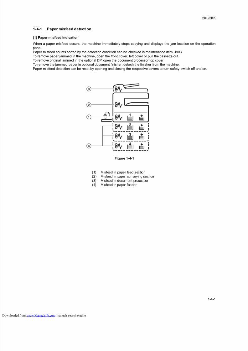
8/18/2019 taskalfa_220
http://slidepdf.com/reader/full/taskalfa220 109/300
2KL/2KK
1-4-1
1-4 Troubleshooting
1-4-1 Paper misfeed detection
(1) Paper misfeed indication
When a paper misfeed occurs, the machine immediately stops copying and displays the jam location on the operation
panel.
Paper misfeed counts sorted by the detection condition can be checked in maintenance item U903.
To remove paper jammed in the machine, open the front cover, left cover or pull the cassette out.
To remove original jammed in the optional DP, open the document processor top cover.To remove the jammed paper in optional document finisher, detach the finisher from the machine.
Paper misfeed detection can be reset by opening and closing the respective covers to turn safety switch off and on.
Figure 1-4-1
(1) Misfeed in paper feed section
(2) Misfeed in paper conveying section
(3) Misfeed in document processor
(4) Misfeed in paper feeder
loaded from www.Manualslib.com manuals search engine
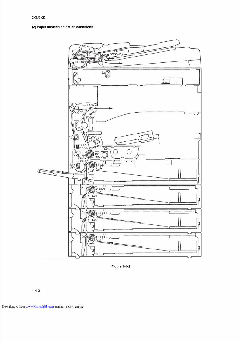
8/18/2019 taskalfa_220
http://slidepdf.com/reader/full/taskalfa220 110/300
2KL/2KK
1-4-2
(2) Paper misfeed detection conditions
Figure 1-4-2
ESW
OSBSW
DPTSW
FSSW
CFSW1
CFSW2
DUPPCSW
RCL
RSWMPSOL
PFCL
CPFCL1
CPFCL2
CPFCL3
loaded from www.Manualslib.com manuals search engine
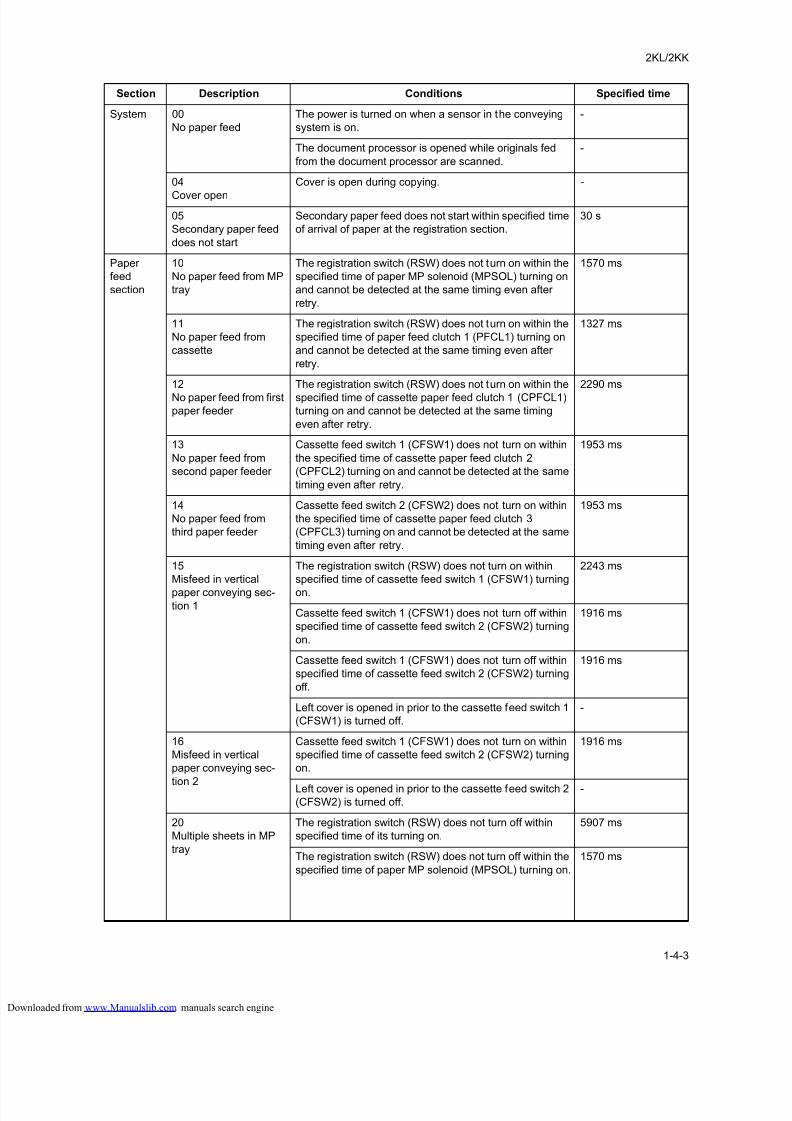
8/18/2019 taskalfa_220
http://slidepdf.com/reader/full/taskalfa220 111/300
2KL/2KK
1-4-3
Section Description Conditions Specified time
System 00
No paper feed
The power is turned on when a sensor in the conveying
system is on.
-
The document processor is opened while originals fed
from the document processor are scanned.
-
04
Cover open
Cover is open during copying. -
05
Secondary paper feed
does not start
Secondary paper feed does not start within specified time
of arrival of paper at the registration section.
30 s
Paper
feed
section
10
No paper feed from MP
tray
The registration switch (RSW) does not turn on within the
specified time of paper MP solenoid (MPSOL) turning on
and cannot be detected at the same timing even after
retry.
1570 ms
11
No paper feed from
cassette
The registration switch (RSW) does not turn on within the
specified time of paper feed clutch 1 (PFCL1) turning on
and cannot be detected at the same timing even after
retry.
1327 ms
12
No paper feed from first
paper feeder
The registration switch (RSW) does not turn on within the
specified time of cassette paper feed clutch 1 (CPFCL1)
turning on and cannot be detected at the same timing
even after retry.
2290 ms
13
No paper feed from
second paper feeder
Cassette feed switch 1 (CFSW1) does not turn on within
the specified time of cassette paper feed clutch 2
(CPFCL2) turning on and cannot be detected at the same
timing even after retry.
1953 ms
14
No paper feed from
third paper feeder
Cassette feed switch 2 (CFSW2) does not turn on within
the specified time of cassette paper feed clutch 3
(CPFCL3) turning on and cannot be detected at the same
timing even after retry.
1953 ms
15
Misfeed in vertical
paper conveying sec-tion 1
The registration switch (RSW) does not turn on within
specified time of cassette feed switch 1 (CFSW1) turning
on.
2243 ms
Cassette feed switch 1 (CFSW1) does not turn off within
specified time of cassette feed switch 2 (CFSW2) turning
on.
1916 ms
Cassette feed switch 1 (CFSW1) does not turn off within
specified time of cassette feed switch 2 (CFSW2) turning
off.
1916 ms
Left cover is opened in prior to the cassette feed switch 1
(CFSW1) is turned off.
-
16
Misfeed in vertical
paper conveying sec-
tion 2
Cassette feed switch 1 (CFSW1) does not turn on within
specified time of cassette feed switch 2 (CFSW2) turning
on.
1916 ms
Left cover is opened in prior to the cassette feed switch 2(CFSW2) is turned off.
-
20
Multiple sheets in MP
tray
The registration switch (RSW) does not turn off within
specified time of its turning on.
5907 ms
The registration switch (RSW) does not turn off within the
specified time of paper MP solenoid (MPSOL) turning on.
1570 ms
loaded from www.Manualslib.com manuals search engine
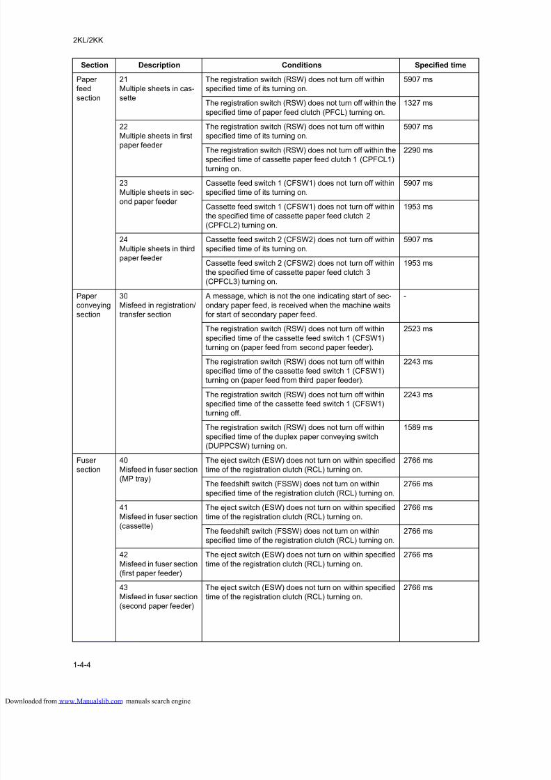
8/18/2019 taskalfa_220
http://slidepdf.com/reader/full/taskalfa220 112/300
2KL/2KK
1-4-4
Paper
feed
section
21
Multiple sheets in cas-
sette
The registration switch (RSW) does not turn off within
specified time of its turning on.
5907 ms
The registration switch (RSW) does not turn off within the
specified time of paper feed clutch (PFCL) turning on.
1327 ms
22
Multiple sheets in firstpaper feeder
The registration switch (RSW) does not turn off within
specified time of its turning on.
5907 ms
The registration switch (RSW) does not turn off within the
specified time of cassette paper feed clutch 1 (CPFCL1)
turning on.
2290 ms
23
Multiple sheets in sec-
ond paper feeder
Cassette feed switch 1 (CFSW1) does not turn off within
specified time of its turning on.
5907 ms
Cassette feed switch 1 (CFSW1) does not turn off within
the specified time of cassette paper feed clutch 2
(CPFCL2) turning on.
1953 ms
24
Multiple sheets in third
paper feeder
Cassette feed switch 2 (CFSW2) does not turn off within
specified time of its turning on.
5907 ms
Cassette feed switch 2 (CFSW2) does not turn off within
the specified time of cassette paper feed clutch 3(CPFCL3) turning on.
1953 ms
Paper
conveying
section
30
Misfeed in registration/
transfer section
A message, which is not the one indicating start of sec-
ondary paper feed, is received when the machine waits
for start of secondary paper feed.
-
The registration switch (RSW) does not turn off within
specified time of the cassette feed switch 1 (CFSW1)
turning on (paper feed from second paper feeder).
2523 ms
The registration switch (RSW) does not turn off within
specified time of the cassette feed switch 1 (CFSW1)
turning on (paper feed from third paper feeder).
2243 ms
The registration switch (RSW) does not turn off within
specified time of the cassette feed switch 1 (CFSW1)
turning off.
2243 ms
The registration switch (RSW) does not turn off within
specified time of the duplex paper conveying switch
(DUPPCSW) turning on.
1589 ms
Fuser
section
40
Misfeed in fuser section
(MP tray)
The eject switch (ESW) does not turn on within specified
time of the registration clutch (RCL) turning on.
2766 ms
The feedshift switch (FSSW) does not turn on within
specified time of the registration clutch (RCL) turning on.
2766 ms
41
Misfeed in fuser section
(cassette)
The eject switch (ESW) does not turn on within specified
time of the registration clutch (RCL) turning on.
2766 ms
The feedshift switch (FSSW) does not turn on within
specified time of the registration clutch (RCL) turning on.
2766 ms
42
Misfeed in fuser section
(first paper feeder)
The eject switch (ESW) does not turn on within specified
time of the registration clutch (RCL) turning on.
2766 ms
43
Misfeed in fuser section
(second paper feeder)
The eject switch (ESW) does not turn on within specified
time of the registration clutch (RCL) turning on.
2766 ms
Section Description Conditions Specified time
loaded from www.Manualslib.com manuals search engine
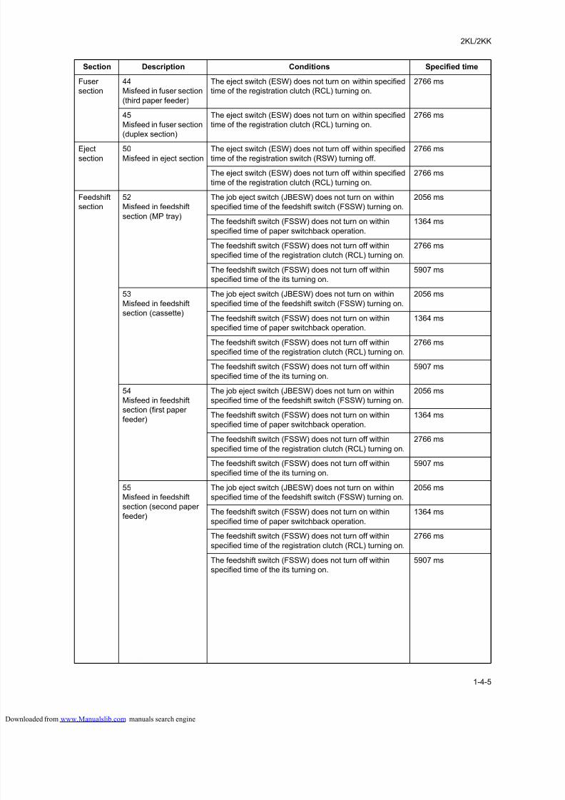
8/18/2019 taskalfa_220
http://slidepdf.com/reader/full/taskalfa220 113/300
2KL/2KK
1-4-5
Fuser
section
44
Misfeed in fuser section
(third paper feeder)
The eject switch (ESW) does not turn on within specified
time of the registration clutch (RCL) turning on.
2766 ms
45
Misfeed in fuser section
(duplex section)
The eject switch (ESW) does not turn on within specified
time of the registration clutch (RCL) turning on.
2766 ms
Eject
section
50
Misfeed in eject section
The eject switch (ESW) does not turn off within specified
time of the registration switch (RSW) turning off.
2766 ms
The eject switch (ESW) does not turn off within specified
time of the registration clutch (RCL) turning on.
2766 ms
Feedshift
section
52
Misfeed in feedshift
section (MP tray)
The job eject switch (JBESW) does not turn on within
specified time of the feedshift switch (FSSW) turning on.
2056 ms
The feedshift switch (FSSW) does not turn on within
specified time of paper switchback operation.
1364 ms
The feedshift switch (FSSW) does not turn off within
specified time of the registration clutch (RCL) turning on.
2766 ms
The feedshift switch (FSSW) does not turn off within
specified time of the its turning on.
5907 ms
53
Misfeed in feedshift
section (cassette)
The job eject switch (JBESW) does not turn on within
specified time of the feedshift switch (FSSW) turning on.
2056 ms
The feedshift switch (FSSW) does not turn on within
specified time of paper switchback operation.
1364 ms
The feedshift switch (FSSW) does not turn off within
specified time of the registration clutch (RCL) turning on.
2766 ms
The feedshift switch (FSSW) does not turn off within
specified time of the its turning on.
5907 ms
54
Misfeed in feedshift
section (first paper
feeder)
The job eject switch (JBESW) does not turn on within
specified time of the feedshift switch (FSSW) turning on.
2056 ms
The feedshift switch (FSSW) does not turn on within
specified time of paper switchback operation.
1364 ms
The feedshift switch (FSSW) does not turn off within
specified time of the registration clutch (RCL) turning on.
2766 ms
The feedshift switch (FSSW) does not turn off within
specified time of the its turning on.
5907 ms
55
Misfeed in feedshift
section (second paper
feeder)
The job eject switch (JBESW) does not turn on within
specified time of the feedshift switch (FSSW) turning on.
2056 ms
The feedshift switch (FSSW) does not turn on within
specified time of paper switchback operation.
1364 ms
The feedshift switch (FSSW) does not turn off within
specified time of the registration clutch (RCL) turning on.
2766 ms
The feedshift switch (FSSW) does not turn off withinspecified time of the its turning on.
5907 ms
Section Description Conditions Specified time
loaded from www.Manualslib.com manuals search engine
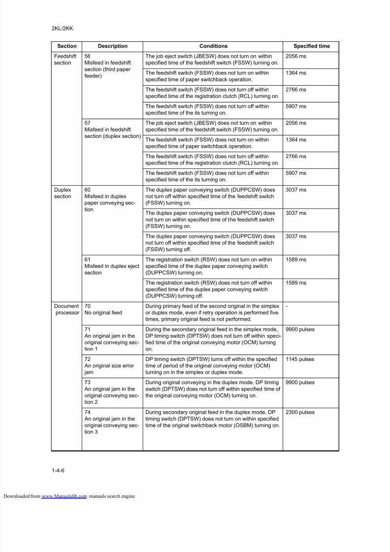
8/18/2019 taskalfa_220
http://slidepdf.com/reader/full/taskalfa220 114/300
2KL/2KK
1-4-6
Feedshift
section
56
Misfeed in feedshift
section (third paper
feeder)
The job eject switch (JBESW) does not turn on within
specified time of the feedshift switch (FSSW) turning on.
2056 ms
The feedshift switch (FSSW) does not turn on within
specified time of paper switchback operation.
1364 ms
The feedshift switch (FSSW) does not turn off within
specified time of the registration clutch (RCL) turning on.
2766 ms
The feedshift switch (FSSW) does not turn off within
specified time of the its turning on.
5907 ms
57
Misfeed in feedshift
section (duplex section)
The job eject switch (JBESW) does not turn on within
specified time of the feedshift switch (FSSW) turning on.
2056 ms
The feedshift switch (FSSW) does not turn on within
specified time of paper switchback operation.
1364 ms
The feedshift switch (FSSW) does not turn off within
specified time of the registration clutch (RCL) turning on.
2766 ms
The feedshift switch (FSSW) does not turn off within
specified time of the its turning on.
5907 ms
Duplex
section
60
Misfeed in duplex
paper conveying sec-
tion
The duplex paper conveying switch (DUPPCSW) does
not turn off within specified time of the feedshift switch
(FSSW) turning on.
3037 ms
The duplex paper conveying switch (DUPPCSW) does
not turn on within specified time of the feedshift switch
(FSSW) turning on.
3037 ms
The duplex paper conveying switch (DUPPCSW) does
not turn off within specified time of the feedshift switch
(FSSW) turning off.
3037 ms
61
Misfeed in duplex eject
section
The registration switch (RSW) does not turn on within
specified time of the duplex paper conveying switch
(DUPPCSW) turning on.
1589 ms
The registration switch (RSW) does not turn off within
specified time of the duplex paper conveying switch(DUPPCSW) turning off.
1589 ms
Document
processor
70
No original feed
During primary feed of the second original in the simplex
or duplex mode, even if retry operation is performed five
times, primary original feed is not performed.
-
71
An original jam in the
original conveying sec-
tion 1
During the secondary original feed in the simplex mode,
DP timing switch (DPTSW) does not turn off within speci-
fied time of the original conveying motor (OCM) turning
on.
9900 pulses
72
An original size error
jam
DP timing switch (DPTSW) turns off within the specified
time of period of the original conveying motor (OCM)
turning on in the simplex or duplex mode.
1145 pulses
73
An original jam in the
original conveying sec-
tion 2
During original conveying in the duplex mode, DP timing
switch (DPTSW) does not turn off within specified time of
the original conveying motor (OCM) turning on.
9900 pulses
74
An original jam in the
original conveying sec-
tion 3
During secondary original feed in the duplex mode, DP
timing switch (DPTSW) does not turn on within specified
time of the original switchback motor (OSBM) turning on.
2300 pulses
Section Description Conditions Specified time
loaded from www.Manualslib.com manuals search engine
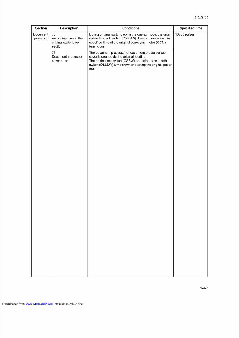
8/18/2019 taskalfa_220
http://slidepdf.com/reader/full/taskalfa220 115/300
2KL/2KK
1-4-7
Document
processor
75
An original jam in the
original switchback
section
During original switchback in the duplex mode, the origi-
nal switchback switch (OSBSW) does not turn on within
specified time of the original conveying motor (OCM)
turning on.
10700 pulses
78
Document processor
cover open
The document processor or document processor top
cover is opened during original feeding.
The original set switch (OSSW) or original size length
switch (OSLSW) turns on when starting the original paper
feed.
-
Section Description Conditions Specified time
loaded from www.Manualslib.com manuals search engine
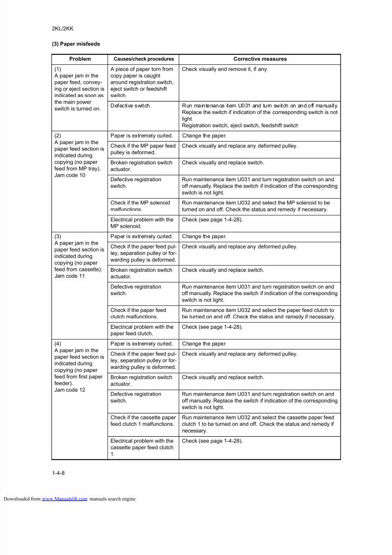
8/18/2019 taskalfa_220
http://slidepdf.com/reader/full/taskalfa220 116/300
2KL/2KK
1-4-8
(3) Paper misfeeds
Problem Causes/check procedures Corrective measures
(1)
A paper jam in the
paper feed, convey-
ing or eject section is
indicated as soon asthe main power
switch is turned on.
A piece of paper torn from
copy paper is caught
around registration switch,
eject switch or feedshift
switch.
Check visually and remove it, if any.
Defective switch. Run maintenance item U031 and turn switch on and off manually.
Replace the switch if indication of the corresponding switch is not
light.
Registration switch, eject switch, feedshift switch
(2)
A paper jam in the
paper feed section is
indicated during
copying (no paper
feed from MP tray).
Jam code 10
Paper is extremely curled. Change the paper.
Check if the MP paper feed
pulley is deformed.
Check visually and replace any deformed pulley.
Broken registration switch
actuator.
Check visually and replace switch.
Defective registration
switch.
Run maintenance item U031 and turn registration switch on and
off manually. Replace the switch if indication of the corresponding
switch is not light.Check if the MP solenoid
malfunctions.
Run maintenance item U032 and select the MP solenoid to be
turned on and off. Check the status and remedy if necessary.
Electrical problem with the
MP solenoid.
Check (see page 1-4-28).
(3)
A paper jam in the
paper feed section is
indicated during
copying (no paper
feed from cassette).
Jam code 11
Paper is extremely curled. Change the paper.
Check if the paper feed pul-
ley, separation pulley or for-
warding pulley is deformed.
Check visually and replace any deformed pulley.
Broken registration switch
actuator.
Check visually and replace switch.
Defective registration
switch.
Run maintenance item U031 and turn registration switch on and
off manually. Replace the switch if indication of the correspondingswitch is not light.
Check if the paper feed
clutch malfunctions.
Run maintenance item U032 and select the paper feed clutch to
be turned on and off. Check the status and remedy if necessary.
Electrical problem with the
paper feed clutch.
Check (see page 1-4-28).
(4)
A paper jam in the
paper feed section is
indicated during
copying (no paper
feed from first paper
feeder).
Jam code 12
Paper is extremely curled. Change the paper.
Check if the paper feed pul-
ley, separation pulley or for-
warding pulley is deformed.
Check visually and replace any deformed pulley.
Broken registration switch
actuator.
Check visually and replace switch.
Defective registration
switch.
Run maintenance item U031 and turn registration switch on and
off manually. Replace the switch if indication of the corresponding
switch is not light.
Check if the cassette paper
feed clutch 1 malfunctions.
Run maintenance item U032 and select the cassette paper feed
clutch 1 to be turned on and off. Check the status and remedy if
necessary.
Electrical problem with the
cassette paper feed clutch
1.
Check (see page 1-4-28).
loaded from www.Manualslib.com manuals search engine
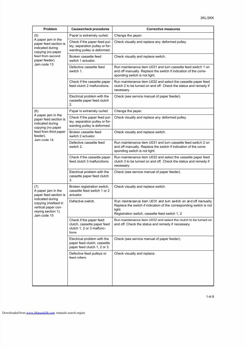
8/18/2019 taskalfa_220
http://slidepdf.com/reader/full/taskalfa220 117/300
2KL/2KK
1-4-9
(5)
A paper jam in the
paper feed section is
indicated during
copying (no paper
feed from second
paper feeder).Jam code 13
Paper is extremely curled. Change the paper.
Check if the paper feed pul-
ley, separation pulley or for-
warding pulley is deformed.
Check visually and replace any deformed pulley.
Broken cassette feed
switch 1 actuator.
Check visually and replace switch.
Defective cassette feed
switch 1.
Run maintenance item U031 and turn cassette feed switch 1 on
and off manually. Replace the switch if indication of the corre-
sponding switch is not light.
Check if the cassette paper
feed clutch 2 malfunctions.
Run maintenance item U032 and select the cassette paper feed
clutch 2 to be turned on and off. Check the status and remedy if
necessary.
Electrical problem with the
cassette paper feed clutch
2.
Check (see service manual of paper feeder).
(6)
A paper jam in the
paper feed section is
indicated during
copying (no paper
feed from third paper
feeder).
Jam code 14
Paper is extremely curled. Change the paper.
Check if the paper feed pul-
ley, separation pulley or for-warding pulley is deformed.
Check visually and replace any deformed pulley.
Broken cassette feed
switch 2 actuator.
Check visually and replace switch.
Defective cassette feed
switch 2.
Run maintenance item U031 and turn cassette feed switch 2 on
and off manually. Replace the switch if indication of the corre-
sponding switch is not light.
Check if the cassette paper
feed clutch 3 malfunctions.
Run maintenance item U032 and select the cassette paper feed
clutch 3 to be turned on and off. Check the status and remedy if
necessary.
Electrical problem with the
cassette paper feed clutch
3.
Check (see service manual of paper feeder).
(7)
A paper jam in the
paper feed section is
indicated during
copying (misfeed in
vertical paper con-
veying section 1).
Jam code 15
Broken registration switch,
cassette feed switch 1 or 2
actuator.
Check visually and replace switch.
Defective switch. Run maintenance item U031 and turn switch on and off manually.
Replace the switch if indication of the corresponding switch is not
light.
Registration switch, cassette feed switch 1, 2
Check if the paper feed
clutch, cassette paper feed
clutch 1, 2 or 3 malfunc-
tions.
Run maintenance item U032 and select the clutch to be turned on
and off. Check the status and remedy if necessary.
Electrical problem with the
paper feed clutch, cassettepaper feed clutch 1, 2 or 3.
Check (see service manual of paper feeder).
Defective feed pulleys or
feed rollers.
Check visually and replace.
Problem Causes/check procedures Corrective measures
loaded from www.Manualslib.com manuals search engine
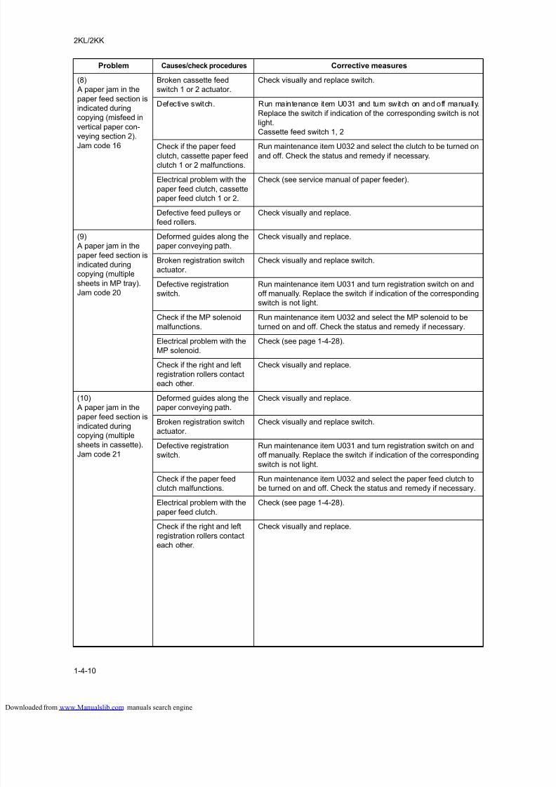
8/18/2019 taskalfa_220
http://slidepdf.com/reader/full/taskalfa220 118/300
2KL/2KK
1-4-10
(8)
A paper jam in the
paper feed section is
indicated during
copying (misfeed in
vertical paper con-
veying section 2).Jam code 16
Broken cassette feed
switch 1 or 2 actuator.
Check visually and replace switch.
Defective switch. Run maintenance item U031 and turn switch on and off manually.
Replace the switch if indication of the corresponding switch is not
light.
Cassette feed switch 1, 2
Check if the paper feed
clutch, cassette paper feed
clutch 1 or 2 malfunctions.
Run maintenance item U032 and select the clutch to be turned on
and off. Check the status and remedy if necessary.
Electrical problem with the
paper feed clutch, cassette
paper feed clutch 1 or 2.
Check (see service manual of paper feeder).
Defective feed pulleys or
feed rollers.
Check visually and replace.
(9)
A paper jam in the
paper feed section is
indicated during
copying (multiplesheets in MP tray).
Jam code 20
Deformed guides along the
paper conveying path.
Check visually and replace.
Broken registration switch
actuator.
Check visually and replace switch.
Defective registration
switch.
Run maintenance item U031 and turn registration switch on and
off manually. Replace the switch if indication of the corresponding
switch is not light.
Check if the MP solenoid
malfunctions.
Run maintenance item U032 and select the MP solenoid to be
turned on and off. Check the status and remedy if necessary.
Electrical problem with the
MP solenoid.
Check (see page 1-4-28).
Check if the right and left
registration rollers contact
each other.
Check visually and replace.
(10)
A paper jam in the
paper feed section is
indicated during
copying (multiple
sheets in cassette).
Jam code 21
Deformed guides along the
paper conveying path.
Check visually and replace.
Broken registration switch
actuator.
Check visually and replace switch.
Defective registration
switch.
Run maintenance item U031 and turn registration switch on and
off manually. Replace the switch if indication of the corresponding
switch is not light.
Check if the paper feed
clutch malfunctions.
Run maintenance item U032 and select the paper feed clutch to
be turned on and off. Check the status and remedy if necessary.
Electrical problem with the
paper feed clutch.
Check (see page 1-4-28).
Check if the right and left
registration rollers contact
each other.
Check visually and replace.
Problem Causes/check procedures Corrective measures
loaded from www.Manualslib.com manuals search engine
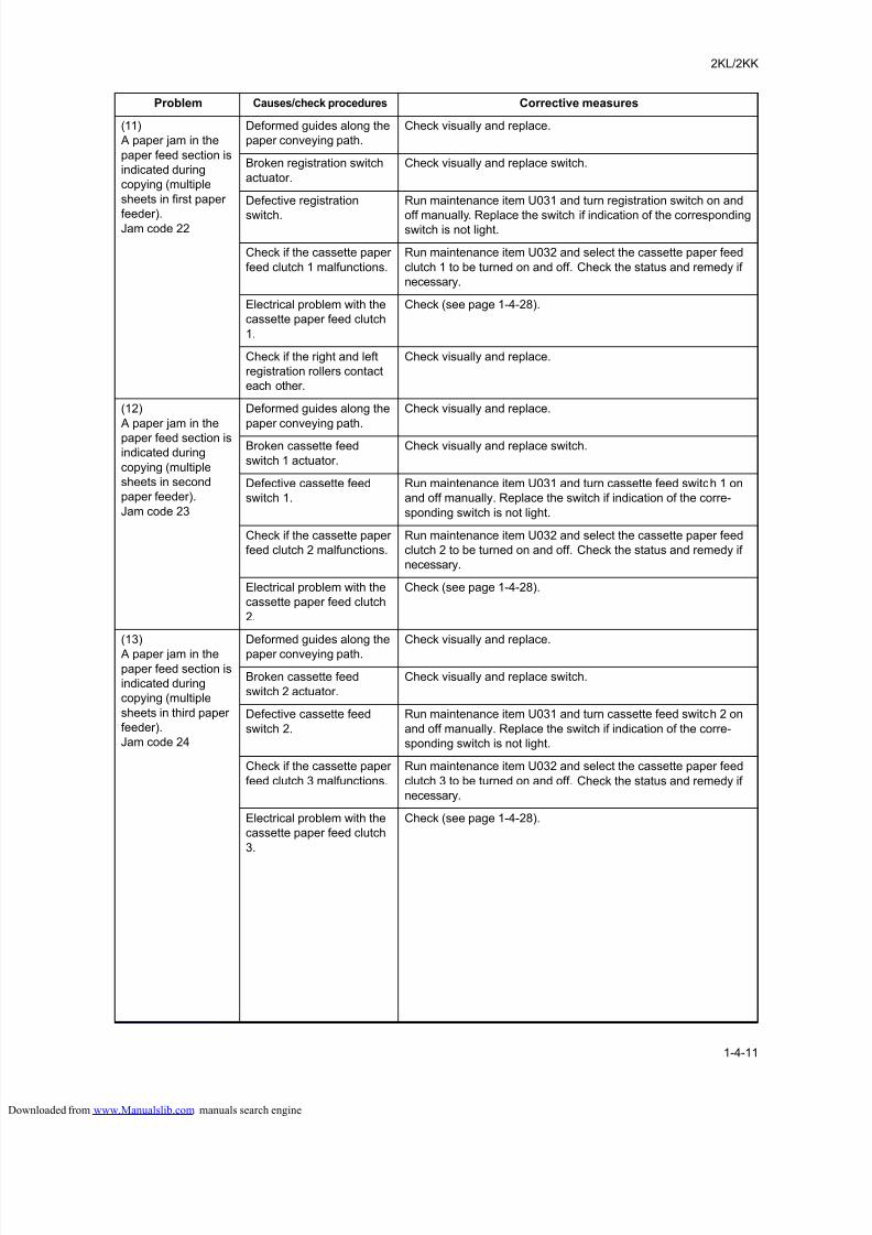
8/18/2019 taskalfa_220
http://slidepdf.com/reader/full/taskalfa220 119/300
2KL/2KK
1-4-11
(11)
A paper jam in the
paper feed section is
indicated during
copying (multiple
sheets in first paper
feeder).Jam code 22
Deformed guides along the
paper conveying path.
Check visually and replace.
Broken registration switch
actuator.
Check visually and replace switch.
Defective registration
switch.
Run maintenance item U031 and turn registration switch on and
off manually. Replace the switch if indication of the correspondingswitch is not light.
Check if the cassette paper
feed clutch 1 malfunctions.
Run maintenance item U032 and select the cassette paper feed
clutch 1 to be turned on and off. Check the status and remedy if
necessary.
Electrical problem with the
cassette paper feed clutch
1.
Check (see page 1-4-28).
Check if the right and left
registration rollers contact
each other.
Check visually and replace.
(12)
A paper jam in the
paper feed section is
indicated during
copying (multiple
sheets in second
paper feeder).
Jam code 23
Deformed guides along the
paper conveying path.
Check visually and replace.
Broken cassette feed
switch 1 actuator.
Check visually and replace switch.
Defective cassette feed
switch 1.
Run maintenance item U031 and turn cassette feed switch 1 on
and off manually. Replace the switch if indication of the corre-
sponding switch is not light.
Check if the cassette paper
feed clutch 2 malfunctions.
Run maintenance item U032 and select the cassette paper feed
clutch 2 to be turned on and off. Check the status and remedy if
necessary.
Electrical problem with the
cassette paper feed clutch
2.
Check (see page 1-4-28).
(13)
A paper jam in the
paper feed section is
indicated during
copying (multiple
sheets in third paper
feeder).
Jam code 24
Deformed guides along the
paper conveying path.
Check visually and replace.
Broken cassette feed
switch 2 actuator.
Check visually and replace switch.
Defective cassette feed
switch 2.
Run maintenance item U031 and turn cassette feed switch 2 on
and off manually. Replace the switch if indication of the corre-
sponding switch is not light.
Check if the cassette paper
feed clutch 3 malfunctions.
Run maintenance item U032 and select the cassette paper feed
clutch 3 to be turned on and off. Check the status and remedy if
necessary.
Electrical problem with the
cassette paper feed clutch
3.
Check (see page 1-4-28).
Problem Causes/check procedures Corrective measures
loaded from www.Manualslib.com manuals search engine
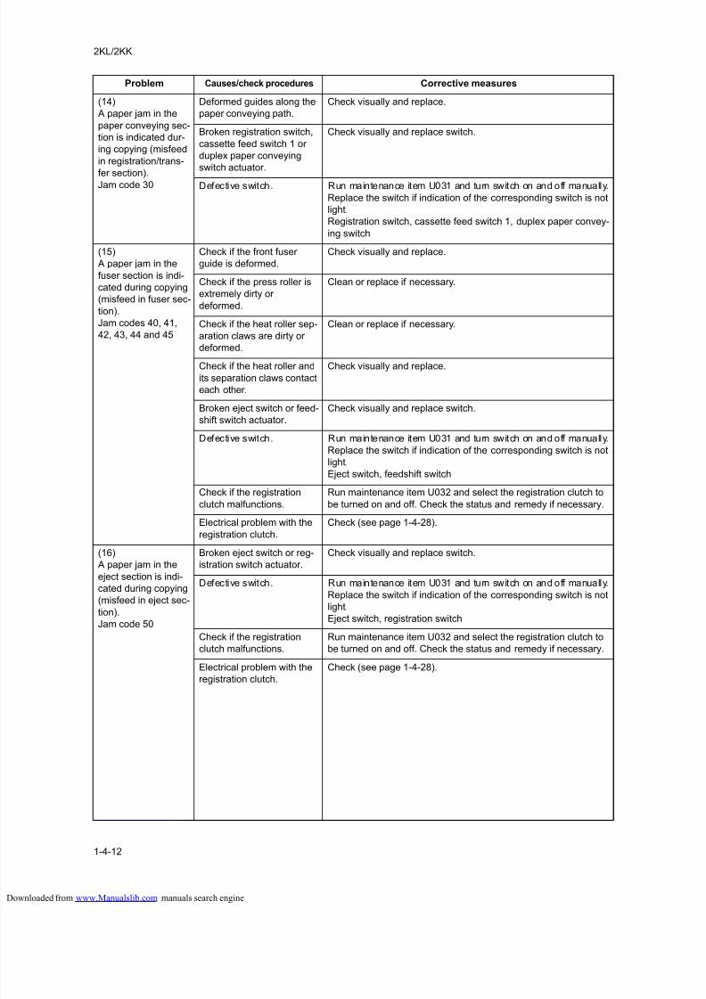
8/18/2019 taskalfa_220
http://slidepdf.com/reader/full/taskalfa220 120/300
2KL/2KK
1-4-12
(14)
A paper jam in the
paper conveying sec-
tion is indicated dur-
ing copying (misfeed
in registration/trans-
fer section).Jam code 30
Deformed guides along the
paper conveying path.
Check visually and replace.
Broken registration switch,
cassette feed switch 1 or
duplex paper conveying
switch actuator.
Check visually and replace switch.
Defective switch. Run maintenance item U031 and turn switch on and off manually.
Replace the switch if indication of the corresponding switch is not
light.
Registration switch, cassette feed switch 1, duplex paper convey-
ing switch
(15)
A paper jam in the
fuser section is indi-
cated during copying
(misfeed in fuser sec-
tion).
Jam codes 40, 41,
42, 43, 44 and 45
Check if the front fuser
guide is deformed.
Check visually and replace.
Check if the press roller is
extremely dirty or
deformed.
Clean or replace if necessary.
Check if the heat roller sep-
aration claws are dirty or
deformed.
Clean or replace if necessary.
Check if the heat roller and
its separation claws contact
each other.
Check visually and replace.
Broken eject switch or feed-
shift switch actuator.
Check visually and replace switch.
Defective switch. Run maintenance item U031 and turn switch on and off manually.
Replace the switch if indication of the corresponding switch is not
light.
Eject switch, feedshift switch
Check if the registration
clutch malfunctions.
Run maintenance item U032 and select the registration clutch to
be turned on and off. Check the status and remedy if necessary.
Electrical problem with theregistration clutch.
Check (see page 1-4-28).
(16)
A paper jam in the
eject section is indi-
cated during copying
(misfeed in eject sec-
tion).
Jam code 50
Broken eject switch or reg-
istration switch actuator.
Check visually and replace switch.
Defective switch. Run maintenance item U031 and turn switch on and off manually.
Replace the switch if indication of the corresponding switch is not
light.
Eject switch, registration switch
Check if the registration
clutch malfunctions.
Run maintenance item U032 and select the registration clutch to
be turned on and off. Check the status and remedy if necessary.
Electrical problem with the
registration clutch.
Check (see page 1-4-28).
Problem Causes/check procedures Corrective measures
loaded from www.Manualslib.com manuals search engine
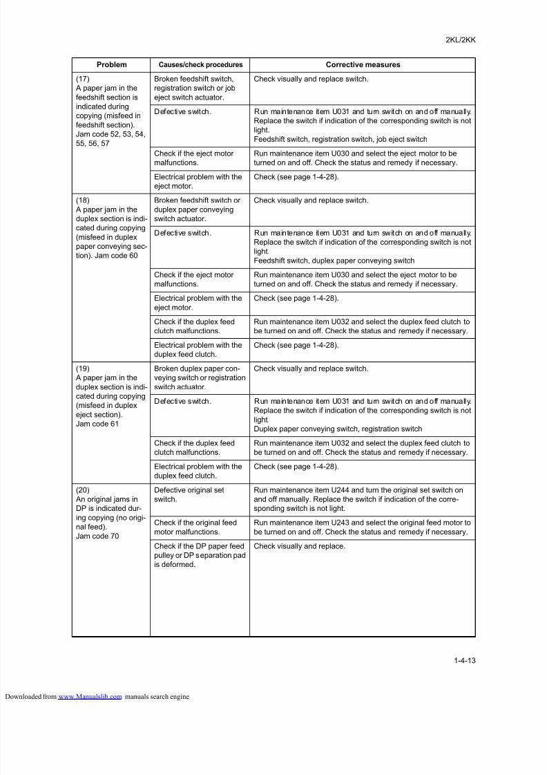
8/18/2019 taskalfa_220
http://slidepdf.com/reader/full/taskalfa220 121/300
2KL/2KK
1-4-13
(17)
A paper jam in the
feedshift section is
indicated during
copying (misfeed in
feedshift section).
Jam code 52, 53, 54,55, 56, 57
Broken feedshift switch,
registration switch or job
eject switch actuator.
Check visually and replace switch.
Defective switch. Run maintenance item U031 and turn switch on and off manually.
Replace the switch if indication of the corresponding switch is not
light.
Feedshift switch, registration switch, job eject switch
Check if the eject motor
malfunctions.
Run maintenance item U030 and select the eject motor to be
turned on and off. Check the status and remedy if necessary.
Electrical problem with the
eject motor.
Check (see page 1-4-28).
(18)
A paper jam in the
duplex section is indi-
cated during copying
(misfeed in duplex
paper conveying sec-
tion). Jam code 60
Broken feedshift switch or
duplex paper conveying
switch actuator.
Check visually and replace switch.
Defective switch. Run maintenance item U031 and turn switch on and off manually.
Replace the switch if indication of the corresponding switch is not
light.
Feedshift switch, duplex paper conveying switch
Check if the eject motor
malfunctions.
Run maintenance item U030 and select the eject motor to be
turned on and off. Check the status and remedy if necessary.
Electrical problem with the
eject motor.
Check (see page 1-4-28).
Check if the duplex feed
clutch malfunctions.
Run maintenance item U032 and select the duplex feed clutch to
be turned on and off. Check the status and remedy if necessary.
Electrical problem with the
duplex feed clutch.
Check (see page 1-4-28).
(19)
A paper jam in the
duplex section is indi-
cated during copying
(misfeed in duplexeject section).
Jam code 61
Broken duplex paper con-
veying switch or registration
switch actuator.
Check visually and replace switch.
Defective switch. Run maintenance item U031 and turn switch on and off manually.
Replace the switch if indication of the corresponding switch is not
light.
Duplex paper conveying switch, registration switch
Check if the duplex feed
clutch malfunctions.
Run maintenance item U032 and select the duplex feed clutch to
be turned on and off. Check the status and remedy if necessary.
Electrical problem with the
duplex feed clutch.
Check (see page 1-4-28).
(20)
An original jams in
DP is indicated dur-
ing copying (no origi-
nal feed).
Jam code 70
Defective original set
switch.
Run maintenance item U244 and turn the original set switch on
and off manually. Replace the switch if indication of the corre-
sponding switch is not light.
Check if the original feed
motor malfunctions.
Run maintenance item U243 and select the original feed motor to
be turned on and off. Check the status and remedy if necessary.
Check if the DP paper feed
pulley or DP separation pad
is deformed.
Check visually and replace.
Problem Causes/check procedures Corrective measures
loaded from www.Manualslib.com manuals search engine
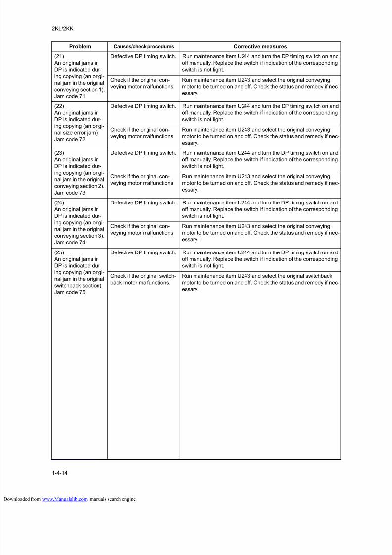
8/18/2019 taskalfa_220
http://slidepdf.com/reader/full/taskalfa220 122/300
2KL/2KK
1-4-14
(21)
An original jams in
DP is indicated dur-
ing copying (an origi-
nal jam in the original
conveying section 1).
Jam code 71
Defective DP timing switch. Run maintenance item U244 and turn the DP timing switch on and
off manually. Replace the switch if indication of the corresponding
switch is not light.
Check if the original con-
veying motor malfunctions.
Run maintenance item U243 and select the original conveying
motor to be turned on and off. Check the status and remedy if nec-
essary.
(22)
An original jams in
DP is indicated dur-
ing copying (an origi-
nal size error jam).
Jam code 72
Defective DP timing switch. Run maintenance item U244 and turn the DP timing switch on and
off manually. Replace the switch if indication of the corresponding
switch is not light.
Check if the original con-
veying motor malfunctions.
Run maintenance item U243 and select the original conveying
motor to be turned on and off. Check the status and remedy if nec-
essary.
(23)
An original jams in
DP is indicated dur-
ing copying (an origi-
nal jam in the original
conveying section 2).
Jam code 73
Defective DP timing switch. Run maintenance item U244 and turn the DP timing switch on and
off manually. Replace the switch if indication of the corresponding
switch is not light.
Check if the original con-
veying motor malfunctions.
Run maintenance item U243 and select the original conveying
motor to be turned on and off. Check the status and remedy if nec-
essary.
(24)
An original jams in
DP is indicated dur-
ing copying (an origi-
nal jam in the original
conveying section 3).
Jam code 74
Defective DP timing switch. Run maintenance item U244 and turn the DP timing switch on and
off manually. Replace the switch if indication of the corresponding
switch is not light.
Check if the original con-
veying motor malfunctions.
Run maintenance item U243 and select the original conveying
motor to be turned on and off. Check the status and remedy if nec-
essary.
(25)
An original jams in
DP is indicated dur-
ing copying (an origi-
nal jam in the original
switchback section).
Jam code 75
Defective DP timing switch. Run maintenance item U244 and turn the DP timing switch on and
off manually. Replace the switch if indication of the corresponding
switch is not light.
Check if the original switch-
back motor malfunctions.
Run maintenance item U243 and select the original switchback
motor to be turned on and off. Check the status and remedy if nec-
essary.
Problem Causes/check procedures Corrective measures
loaded from www.Manualslib.com manuals search engine
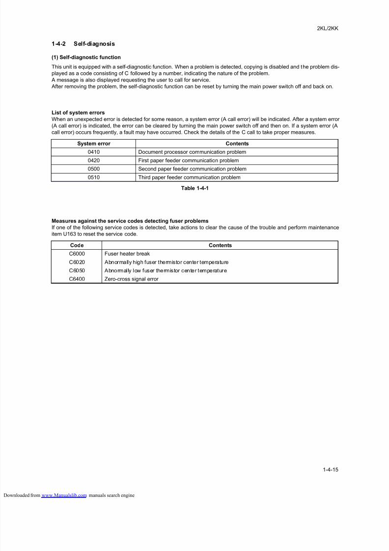
8/18/2019 taskalfa_220
http://slidepdf.com/reader/full/taskalfa220 123/300
2KL/2KK
1-4-15
1-4-2 Self-diagnosis
(1) Self-diagnostic function
This unit is equipped with a self-diagnostic function. When a problem is detected, copying is disabled and the problem dis-
played as a code consisting of C followed by a number, indicating the nature of the problem.
A message is also displayed requesting the user to call for service.
After removing the problem, the self-diagnostic function can be reset by turning the main power switch off and back on.
List of system errors
When an unexpected error is detected for some reason, a system error (A call error) will be indicated. After a system error
(A call error) is indicated, the error can be cleared by turning the main power switch off and then on. If a system error (A
call error) occurs frequently, a fault may have occurred. Check the details of the C call to take proper measures.
Table 1-4-1
Measures against the service codes detecting fuser problems
If one of the following service codes is detected, take actions to clear the cause of the trouble and perform maintenance
item U163 to reset the service code.
System error Contents
0410 Document processor communication problem
0420 First paper feeder communication problem
0500 Second paper feeder communication problem
0510 Third paper feeder communication problem
Code Contents
C6000 Fuser heater break
C6020 Abnormally high fuser thermistor center temperature
C6050 Abnormally low fuser thermistor center temperature
C6400 Zero-cross signal error
loaded from www.Manualslib.com manuals search engine
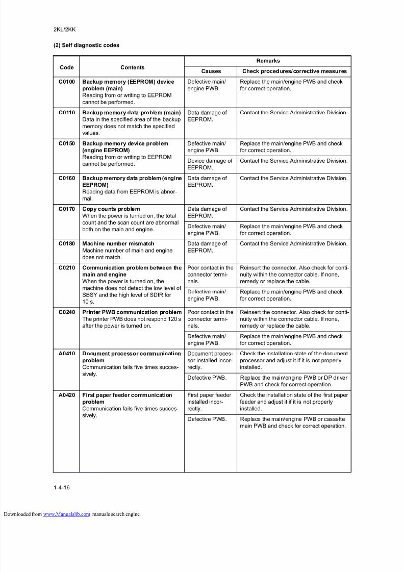
8/18/2019 taskalfa_220
http://slidepdf.com/reader/full/taskalfa220 124/300
2KL/2KK
1-4-16
(2) Self diagnostic codes
Code Contents
Remarks
Causes Check procedures/corrective measures
C0100 Backup memory (EEPROM) device
problem (main)
Reading from or writing to EEPROM
cannot be performed.
Defective main/
engine PWB.
Replace the main/engine PWB and check
for correct operation.
C0110 Backup memory data problem (main)
Data in the specified area of the backup
memory does not match the specified
values.
Data damage of
EEPROM.
Contact the Service Administrative Division.
C0150 Backup memory device problem
(engine EEPROM)
Reading from or writing to EEPROM
cannot be performed.
Defective main/
engine PWB.
Replace the main/engine PWB and check
for correct operation.
Device damage of
EEPROM.
Contact the Service Administrative Division.
C0160 Backup memory data problem (engine
EEPROM)
Reading data from EEPROM is abnor-
mal.
Data damage of
EEPROM.
Contact the Service Administrative Division.
C0170 Copy counts problem
When the power is turned on, the total
count and the scan count are abnormal
both on the main and engine.
Data damage of
EEPROM.
Contact the Service Administrative Division.
Defective main/
engine PWB.
Replace the main/engine PWB and check
for correct operation.
C0180 Machine number mismatch
Machine number of main and engine
does not match.
Data damage of
EEPROM.
Contact the Service Administrative Division.
C0210 Communication problem between the
main and engine
When the power is turned on, the
machine does not detect the low level of
SBSY and the high level of SDIR for
10 s.
Poor contact in the
connector termi-
nals.
Reinsert the connector. Also check for conti-
nuity within the connector cable. If none,
remedy or replace the cable.
Defective main/
engine PWB.
Replace the main/engine PWB and check
for correct operation.
C0240 Printer PWB communication problem
The printer PWB does not respond 120 s
after the power is turned on.
Poor contact in the
connector termi-
nals.
Reinsert the connector. Also check for conti-
nuity within the connector cable. If none,
remedy or replace the cable.
Defective main/
engine PWB.
Replace the main/engine PWB and check
for correct operation.
A0410 Document processor communication
problem
Communication fails five times succes-
sively.
Document proces-
sor installed incor-
rectly.
Check the installation state of the document
processor and adjust it if it is not properly
installed.
Defective PWB. Replace the main/engine PWB or DP driver
PWB and check for correct operation.
A0420 First paper feeder communication
problemCommunication fails five times succes-
sively.
First paper feeder
installed incor-rectly.
Check the installation state of the first paper
feeder and adjust it if it is not properlyinstalled.
Defective PWB. Replace the main/engine PWB or cassette
main PWB and check for correct operation.
loaded from www.Manualslib.com manuals search engine
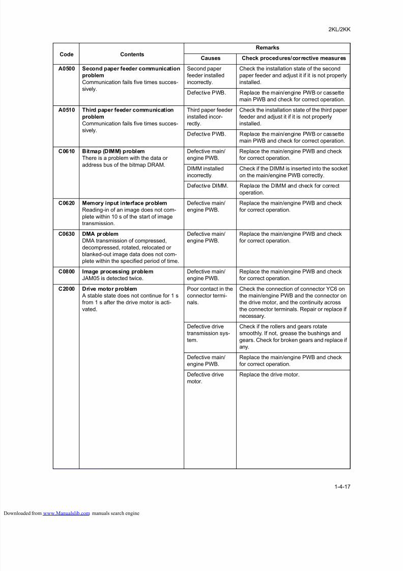
8/18/2019 taskalfa_220
http://slidepdf.com/reader/full/taskalfa220 125/300
2KL/2KK
1-4-17
A0500 Second paper feeder communication
problem
Communication fails five times succes-
sively.
Second paper
feeder installed
incorrectly.
Check the installation state of the second
paper feeder and adjust it if it is not properly
installed.
Defective PWB. Replace the main/engine PWB or cassette
main PWB and check for correct operation.
A0510 Third paper feeder communication
problem
Communication fails five times succes-
sively.
Third paper feeder
installed incor-
rectly.
Check the installation state of the third paper
feeder and adjust it if it is not properly
installed.
Defective PWB. Replace the main/engine PWB or cassette
main PWB and check for correct operation.
C0610 Bitmap (DIMM) problem
There is a problem with the data or
address bus of the bitmap DRAM.
Defective main/
engine PWB.
Replace the main/engine PWB and check
for correct operation.
DIMM installed
incorrectly.
Check if the DIMM is inserted into the socket
on the main/engine PWB correctly.
Defective DIMM. Replace the DIMM and check for correct
operation.
C0620 Memory input interface problem
Reading-in of an image does not com-
plete within 10 s of the start of image
transmission.
Defective main/
engine PWB.
Replace the main/engine PWB and check
for correct operation.
C0630 DMA problem
DMA transmission of compressed,
decompressed, rotated, relocated or
blanked-out image data does not com-
plete within the specified period of time.
Defective main/
engine PWB.
Replace the main/engine PWB and check
for correct operation.
C0800 Image processing problem
JAM05 is detected twice.
Defective main/
engine PWB.
Replace the main/engine PWB and check
for correct operation.
C2000 Drive motor problem
A stable state does not continue for 1 s
from 1 s after the drive motor is acti-
vated.
Poor contact in the
connector termi-
nals.
Check the connection of connector YC6 on
the main/engine PWB and the connector on
the drive motor, and the continuity across
the connector terminals. Repair or replace if
necessary.
Defective drive
transmission sys-
tem.
Check if the rollers and gears rotate
smoothly. If not, grease the bushings and
gears. Check for broken gears and replace if
any.
Defective main/
engine PWB.
Replace the main/engine PWB and check
for correct operation.
Defective drive
motor.
Replace the drive motor.
Code Contents
Remarks
Causes Check procedures/corrective measures
loaded from www.Manualslib.com manuals search engine
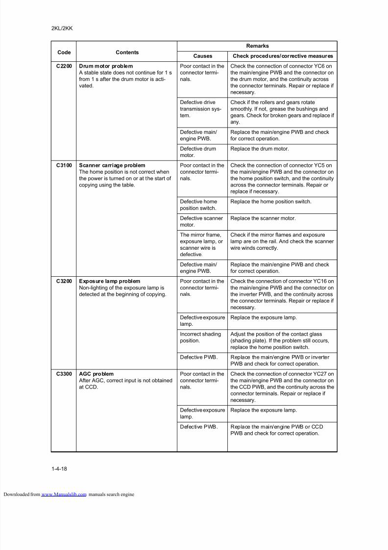
8/18/2019 taskalfa_220
http://slidepdf.com/reader/full/taskalfa220 126/300
2KL/2KK
1-4-18
C2200 Drum motor problem
A stable state does not continue for 1 s
from 1 s after the drum motor is acti-
vated.
Poor contact in the
connector termi-
nals.
Check the connection of connector YC6 on
the main/engine PWB and the connector on
the drum motor, and the continuity across
the connector terminals. Repair or replace if
necessary.
Defective drive
transmission sys-
tem.
Check if the rollers and gears rotate
smoothly. If not, grease the bushings and
gears. Check for broken gears and replace if
any.
Defective main/
engine PWB.
Replace the main/engine PWB and check
for correct operation.
Defective drum
motor.
Replace the drum motor.
C3100 Scanner carriage problem
The home position is not correct when
the power is turned on or at the start of
copying using the table.
Poor contact in the
connector termi-
nals.
Check the connection of connector YC5 on
the main/engine PWB and the connector on
the home position switch, and the continuity
across the connector terminals. Repair or
replace if necessary.
Defective home
position switch.
Replace the home position switch.
Defective scanner
motor.
Replace the scanner motor.
The mirror frame,
exposure lamp, or
scanner wire is
defective.
Check if the mirror flames and exposure
lamp are on the rail. And check the scanner
wire winds correctly.
Defective main/
engine PWB.
Replace the main/engine PWB and check
for correct operation.
C3200 Exposure lamp problem
Non-lighting of the exposure lamp isdetected at the beginning of copying.
Poor contact in the
connector termi-nals.
Check the connection of connector YC16 on
the main/engine PWB and the connector onthe inverter PWB, and the continuity across
the connector terminals. Repair or replace if
necessary.
Defective exposure
lamp.
Replace the exposure lamp.
Incorrect shading
position.
Adjust the position of the contact glass
(shading plate). If the problem still occurs,
replace the home position switch.
Defective PWB. Replace the main/engine PWB or inverter
PWB and check for correct operation.
C3300 AGC problem
After AGC, correct input is not obtained
at CCD.
Poor contact in the
connector termi-
nals.
Check the connection of connector YC27 on
the main/engine PWB and the connector on
the CCD PWB, and the continuity across theconnector terminals. Repair or replace if
necessary.
Defective exposure
lamp.
Replace the exposure lamp.
Defective PWB. Replace the main/engine PWB or CCD
PWB and check for correct operation.
Code Contents
Remarks
Causes Check procedures/corrective measures
loaded from www.Manualslib.com manuals search engine
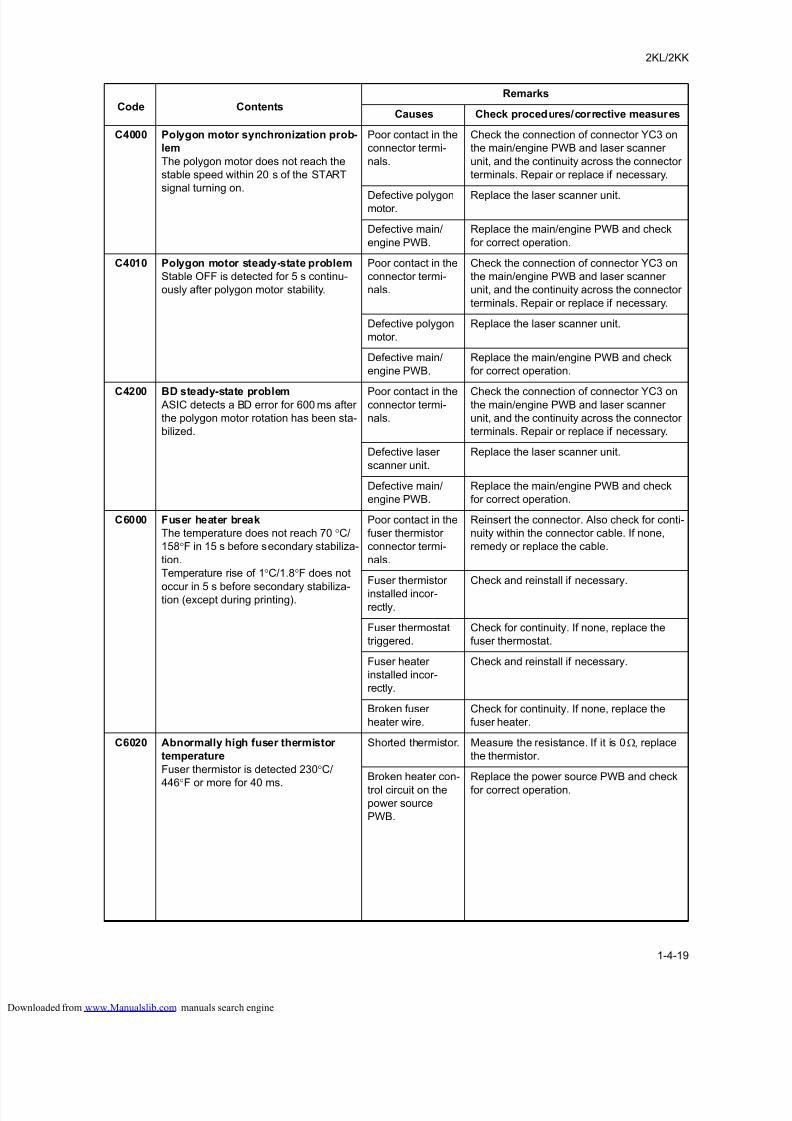
8/18/2019 taskalfa_220
http://slidepdf.com/reader/full/taskalfa220 127/300
2KL/2KK
1-4-19
C4000 Polygon motor synchronization prob-
lem
The polygon motor does not reach the
stable speed within 20 s of the START
signal turning on.
Poor contact in the
connector termi-
nals.
Check the connection of connector YC3 on
the main/engine PWB and laser scanner
unit, and the continuity across the connector
terminals. Repair or replace if necessary.
Defective polygonmotor.
Replace the laser scanner unit.
Defective main/
engine PWB.
Replace the main/engine PWB and check
for correct operation.
C4010 Polygon motor steady-state problem
Stable OFF is detected for 5 s continu-
ously after polygon motor stability.
Poor contact in the
connector termi-
nals.
Check the connection of connector YC3 on
the main/engine PWB and laser scanner
unit, and the continuity across the connector
terminals. Repair or replace if necessary.
Defective polygon
motor.
Replace the laser scanner unit.
Defective main/
engine PWB.
Replace the main/engine PWB and check
for correct operation.
C4200 BD steady-state problem ASIC detects a BD error for 600 ms after
the polygon motor rotation has been sta-
bilized.
Poor contact in theconnector termi-
nals.
Check the connection of connector YC3 onthe main/engine PWB and laser scanner
unit, and the continuity across the connector
terminals. Repair or replace if necessary.
Defective laser
scanner unit.
Replace the laser scanner unit.
Defective main/
engine PWB.
Replace the main/engine PWB and check
for correct operation.
C6000 Fuser heater break
The temperature does not reach 70 °C/
158°F in 15 s before secondary stabiliza-
tion.
Temperature rise of 1°C/1.8°F does not
occur in 5 s before secondary stabiliza-tion (except during printing).
Poor contact in the
fuser thermistor
connector termi-
nals.
Reinsert the connector. Also check for conti-
nuity within the connector cable. If none,
remedy or replace the cable.
Fuser thermistor
installed incor-
rectly.
Check and reinstall if necessary.
Fuser thermostat
triggered.
Check for continuity. If none, replace the
fuser thermostat.
Fuser heater
installed incor-
rectly.
Check and reinstall if necessary.
Broken fuser
heater wire.
Check for continuity. If none, replace the
fuser heater.
C6020 Abnormally high fuser thermistor
temperature
Fuser thermistor is detected 230°C/
446°F or more for 40 ms.
Shorted thermistor. Measure the resistance. If it is 0 Ω, replace
the thermistor.
Broken heater con-
trol circuit on the
power source
PWB.
Replace the power source PWB and check
for correct operation.
Code Contents
Remarks
Causes Check procedures/corrective measures
loaded from www.Manualslib.com manuals search engine
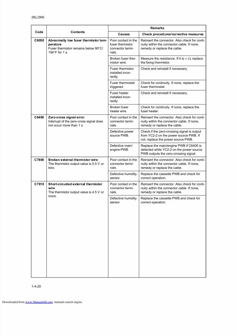
8/18/2019 taskalfa_220
http://slidepdf.com/reader/full/taskalfa220 128/300
2KL/2KK
1-4-20
C6050 Abnormally low fuser thermistor tem-
perature
Fuser thermistor remains below 90°C/
194°F for 1 s.
Poor contact in the
fuser thermistor
connector termi-
nals.
Reinsert the connector. Also check for conti-
nuity within the connector cable. If none,
remedy or replace the cable.
Broken fuser ther-mistor wire.
Measure the resistance. If it is ∞ Ω, replacethe fixing thermistor.
Fuser thermistor
installed incor-
rectly.
Check and reinstall if necessary.
Fuser thermostat
triggered.
Check for continuity. If none, replace the
fuser thermostat.
Fuser heater
installed incor-
rectly.
Check and reinstall if necessary.
Broken fuser
heater wire.
Check for continuity. If none, replace the
fuser heater.
C6400 Zero-cross signal error Interrupt of the zero-cross signal does
not occur more than 1 s.
Poor contact in theconnector termi-
nals.
Reinsert the connector. Also check for conti-nuity within the connector cable. If none,
remedy or replace the cable.
Defective power
source PWB.
Check if the zero-crossing signal is output
from YC2-2 on the power source PWB. If
not, replace the power source PWB.
Defective main/
engine PWB.
Replace the main/engine PWB if C6400 is
detected while YC2-2 on the power source
PWB outputs the zero-crossing signal.
C7800 Broken external thermistor wire
The thermistor output value is 0.5 V or
less.
Poor contact in the
connector termi-
nals.
Reinsert the connector. Also check for conti-
nuity within the connector cable. If none,
remedy or replace the cable.
Defective humidity
sensor.
Replace the cassette PWB and check for
correct operation.
C7810 Short-circuited external thermistor
wire
The thermistor output value is 4.5 V or
more.
Poor contact in the
connector termi-
nals.
Reinsert the connector. Also check for conti-
nuity within the connector cable. If none,
remedy or replace the cable.
Defective humidity
sensor.
Replace the cassette PWB and check for
correct operation.
Code Contents
Remarks
Causes Check procedures/corrective measures
loaded from www.Manualslib.com manuals search engine
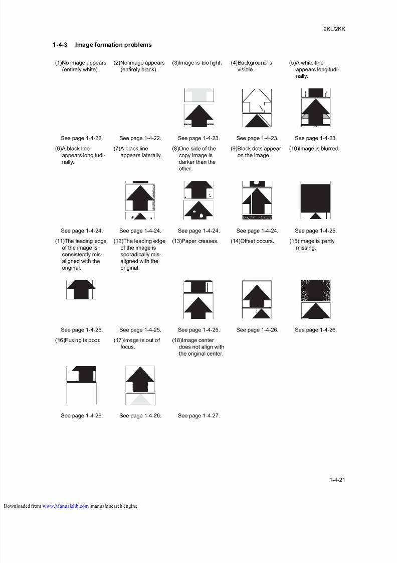
8/18/2019 taskalfa_220
http://slidepdf.com/reader/full/taskalfa220 129/300
2KL/2KK
1-4-21
1-4-3 Image formation problems
(1)No image appears
(entirely white).
(2)No image appears
(entirely black).
(3)Image is too light. (4)Background is
visible.
(5)A white line
appears longitudi-
nally.
See page 1-4-22. See page 1-4-22. See page 1-4-23. See page 1-4-23. See page 1-4-23.
(6)A black line
appears longitudi-
nally.
(7)A black line
appears laterally.
(8)One side of the
copy image is
darker than the
other.
(9)Black dots appear
on the image.
(10)Image is blurred.
See page 1-4-24. See page 1-4-24. See page 1-4-24. See page 1-4-24. See page 1-4-25.
(11)The leading edge
of the image is
consistently mis-
aligned with the
original.
(12)The leading edge
of the image is
sporadically mis-
aligned with the
original.
(13)Paper creases. (14)Offset occurs. (15)Image is partly
missing.
See page 1-4-25. See page 1-4-25. See page 1-4-25. See page 1-4-26. See page 1-4-26.
(16)Fusing is poor. (17)Image is out of
focus.
(18)Image center
does not align with
the original center.
See page 1-4-26. See page 1-4-26. See page 1-4-27.
loaded from www.Manualslib.com manuals search engine
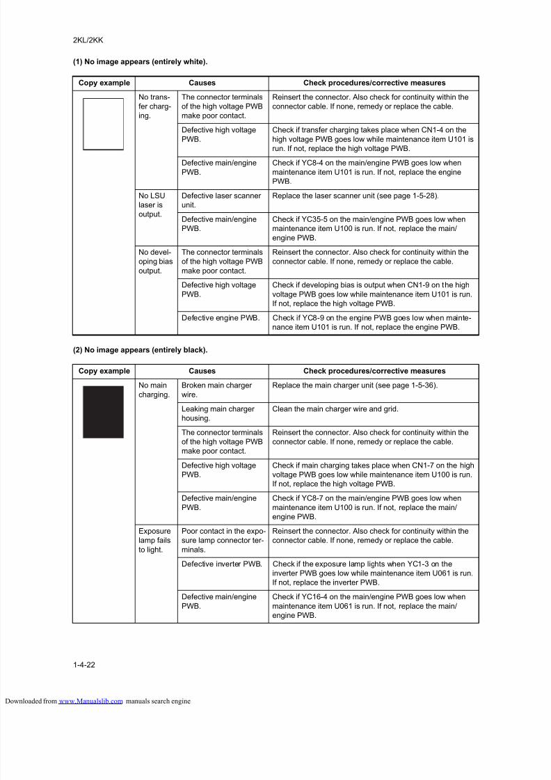
8/18/2019 taskalfa_220
http://slidepdf.com/reader/full/taskalfa220 130/300
2KL/2KK
1-4-22
(1) No image appears (entirely white).
(2) No image appears (entirely black).
Copy example Causes Check procedures/corrective measures
No trans-
fer charg-
ing.
The connector terminals
of the high voltage PWB
make poor contact.
Reinsert the connector. Also check for continuity within the
connector cable. If none, remedy or replace the cable.
Defective high voltage
PWB.
Check if transfer charging takes place when CN1-4 on the
high voltage PWB goes low while maintenance item U101 isrun. If not, replace the high voltage PWB.
Defective main/engine
PWB.
Check if YC8-4 on the main/engine PWB goes low when
maintenance item U101 is run. If not, replace the engine
PWB.
No LSU
laser is
output.
Defective laser scanner
unit.
Replace the laser scanner unit (see page 1-5-28).
Defective main/engine
PWB.
Check if YC35-5 on the main/engine PWB goes low when
maintenance item U100 is run. If not, replace the main/
engine PWB.
No devel-
oping bias
output.
The connector terminals
of the high voltage PWB
make poor contact.
Reinsert the connector. Also check for continuity within the
connector cable. If none, remedy or replace the cable.
Defective high voltage
PWB.
Check if developing bias is output when CN1-9 on the high
voltage PWB goes low while maintenance item U101 is run.
If not, replace the high voltage PWB.
Defective engine PWB. Check if YC8-9 on the engine PWB goes low when mainte-
nance item U101 is run. If not, replace the engine PWB.
Copy example Causes Check procedures/corrective measures
No main
charging.
Broken main charger
wire.
Replace the main charger unit (see page 1-5-36).
Leaking main chargerhousing.
Clean the main charger wire and grid.
The connector terminals
of the high voltage PWB
make poor contact.
Reinsert the connector. Also check for continuity within the
connector cable. If none, remedy or replace the cable.
Defective high voltage
PWB.
Check if main charging takes place when CN1-7 on the high
voltage PWB goes low while maintenance item U100 is run.
If not, replace the high voltage PWB.
Defective main/engine
PWB.
Check if YC8-7 on the main/engine PWB goes low when
maintenance item U100 is run. If not, replace the main/
engine PWB.
Exposure
lamp fails
to light.
Poor contact in the expo-
sure lamp connector ter-
minals.
Reinsert the connector. Also check for continuity within the
connector cable. If none, remedy or replace the cable.
Defective inverter PWB. Check if the exposure lamp lights when YC1-3 on the
inverter PWB goes low while maintenance item U061 is run.
If not, replace the inverter PWB.
Defective main/engine
PWB.
Check if YC16-4 on the main/engine PWB goes low when
maintenance item U061 is run. If not, replace the main/
engine PWB.
loaded from www.Manualslib.com manuals search engine
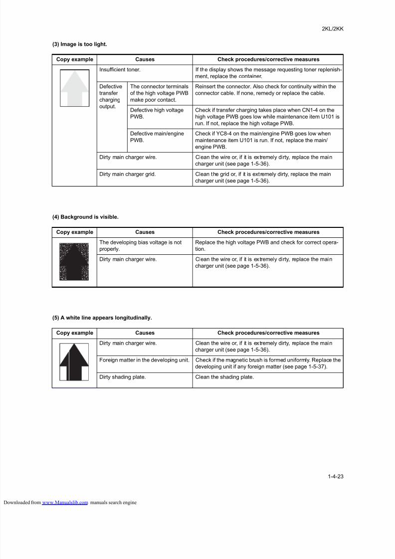
8/18/2019 taskalfa_220
http://slidepdf.com/reader/full/taskalfa220 131/300
2KL/2KK
1-4-23
(3) Image is too light.
(4) Background is visible.
(5) A white line appears longitudinally.
Copy example Causes Check procedures/corrective measures
Insufficient toner. If the display shows the message requesting toner replenish-
ment, replace the container.
Defective
transfer
chargingoutput.
The connector terminals
of the high voltage PWB
make poor contact.
Reinsert the connector. Also check for continuity within the
connector cable. If none, remedy or replace the cable.
Defective high voltage
PWB.
Check if transfer charging takes place when CN1-4 on the
high voltage PWB goes low while maintenance item U101 is
run. If not, replace the high voltage PWB.
Defective main/engine
PWB.
Check if YC8-4 on the main/engine PWB goes low when
maintenance item U101 is run. If not, replace the main/
engine PWB.
Dirty main charger wire. Clean the wire or, if it is extremely dirty, replace the main
charger unit (see page 1-5-36).
Dirty main charger grid. Clean the grid or, if it is extremely dirty, replace the main
charger unit (see page 1-5-36).
Copy example Causes Check procedures/corrective measures
The developing bias voltage is not
properly.
Replace the high voltage PWB and check for correct opera-
tion.
Dirty main charger wire. Clean the wire or, if it is extremely dirty, replace the main
charger unit (see page 1-5-36).
Copy example Causes Check procedures/corrective measures
Dirty main charger wire. Clean the wire or, if it is extremely dirty, replace the main
charger unit (see page 1-5-36).
Foreign matter in the developing unit. Check if the magnetic brush is formed uniformly. Replace the
developing unit if any foreign matter (see page 1-5-37).
Dirty shading plate. Clean the shading plate.
loaded from www.Manualslib.com manuals search engine
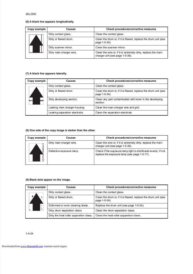
8/18/2019 taskalfa_220
http://slidepdf.com/reader/full/taskalfa220 132/300
2KL/2KK
1-4-24
(6) A black line appears longitudinally.
(7) A black line appears laterally.
(8) One side of the copy image is darker than the other.
(9) Black dots appear on the image.
Copy example Causes Check procedures/corrective measures
Dirty contact glass. Clean the contact glass.
Dirty or flawed drum. Clean the drum or, if it is flawed, replace the drum unit (see
page 1-5-34).
Dirty scanner mirror. Clean the scanner mirror.
Dirty main charger wire. Clean the wire or, if it is extremely dirty, replace the main
charger unit (see page 1-5-36).
Copy example Causes Check procedures/corrective measures
Dirty contact glass. Clean the contact glass.
Dirty or flawed drum. Clean the drum or, if it is flawed, replace the drum unit (see
page 1-5-34).
Dirty developing section. Clean any part contaminated with toner in the developing
section.
Leaking main charger housing. Clean the main charger wire and grid.
Leaking separation electrode. Clean the separation electrode.
Copy example Causes Check procedures/corrective measures
Dirty main charger wire. Clean the wire or, if it is extremely dirty, replace the maincharger unit (see page 1-5-36).
Defective exposure lamp. Check if the exposure lamp light is distributed evenly. If not,
replace the exposure lamp (see page 1-5-17).
Copy example Causes Check procedures/corrective measures
Dirty contact glass. Clean the contact glass.
Dirty or flawed drum. Clean the drum or, if it is flawed, replace the drum unit (see
page 1-5-34).
Deformed or worn cleaning blade. Replace the drum unit (see page 1-5-34).
Dirty drum separation claws. Clean the drum separation claws.
Dirty the heat roller separation claws. Clean the heat roller separation claws.
loaded from www.Manualslib.com manuals search engine
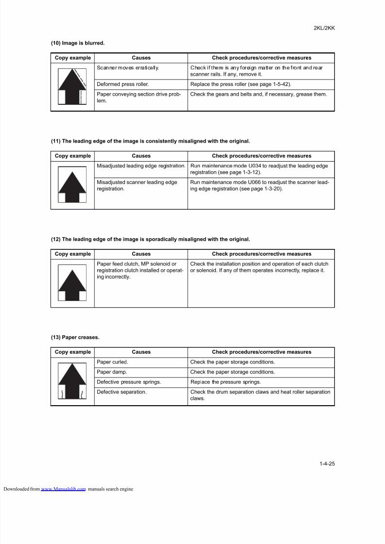
8/18/2019 taskalfa_220
http://slidepdf.com/reader/full/taskalfa220 133/300
2KL/2KK
1-4-25
(10) Image is blurred.
(11) The leading edge of the image is consistently misaligned with the original.
(12) The leading edge of the image is sporadically misaligned with the original.
(13) Paper creases.
Copy example Causes Check procedures/corrective measures
Scanner moves erratically. Check if there is any foreign matter on the front and rear
scanner rails. If any, remove it.
Deformed press roller. Replace the press roller (see page 1-5-42).
Paper conveying section drive prob-lem.
Check the gears and belts and, if necessary, grease them.
Copy example Causes Check procedures/corrective measures
Misadjusted leading edge registration. Run maintenance mode U034 to readjust the leading edge
registration (see page 1-3-12).
Misadjusted scanner leading edge
registration.
Run maintenance mode U066 to readjust the scanner lead-
ing edge registration (see page 1-3-20).
Copy example Causes Check procedures/corrective measures
Paper feed clutch, MP solenoid or
registration clutch installed or operat-
ing incorrectly.
Check the installation position and operation of each clutch
or solenoid. If any of them operates incorrectly, replace it.
Copy example Causes Check procedures/corrective measures
Paper curled. Check the paper storage conditions.
Paper damp. Check the paper storage conditions.
Defective pressure springs. Replace the pressure springs.
Defective separation. Check the drum separation claws and heat roller separation
claws.
loaded from www.Manualslib.com manuals search engine
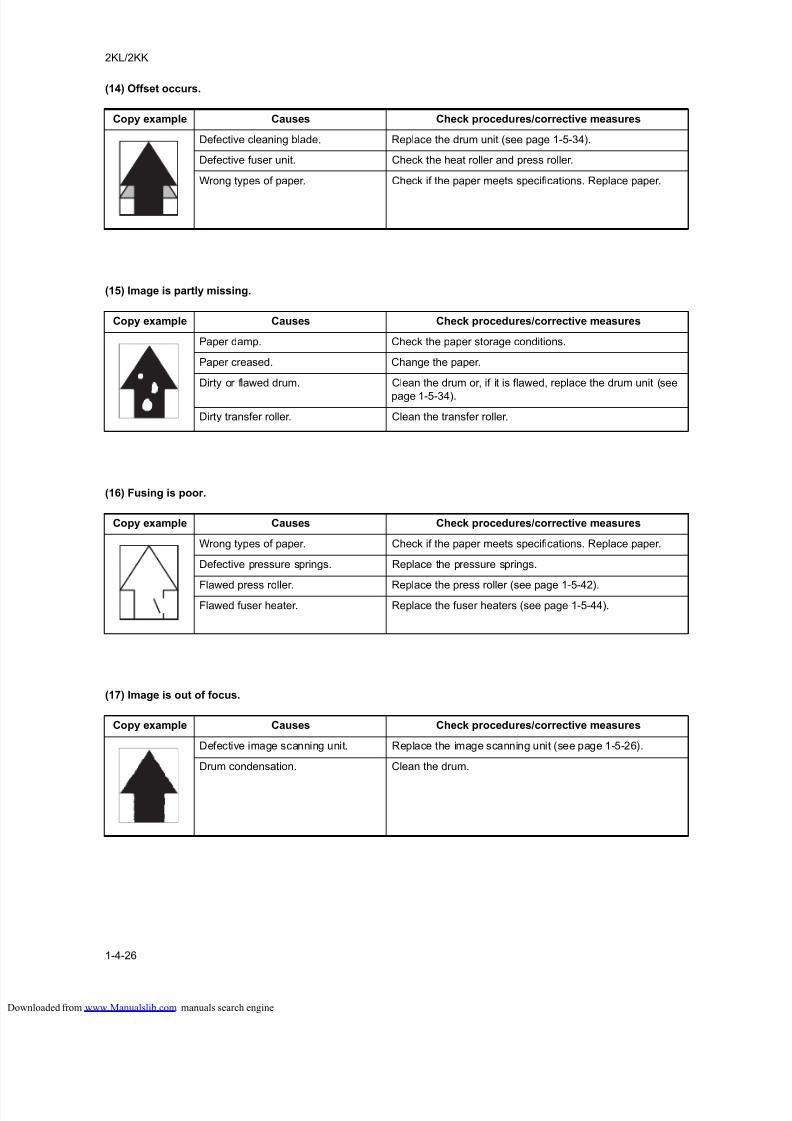
8/18/2019 taskalfa_220
http://slidepdf.com/reader/full/taskalfa220 134/300
2KL/2KK
1-4-26
(14) Offset occurs.
(15) Image is partly missing.
(16) Fusing is poor.
(17) Image is out of focus.
Copy example Causes Check procedures/corrective measures
Defective cleaning blade. Replace the drum unit (see page 1-5-34).
Defective fuser unit. Check the heat roller and press roller.
Wrong types of paper. Check if the paper meets specifications. Replace paper.
Copy example Causes Check procedures/corrective measures
Paper damp. Check the paper storage conditions.
Paper creased. Change the paper.
Dirty or flawed drum. Clean the drum or, if it is flawed, replace the drum unit (see
page 1-5-34).
Dirty transfer roller. Clean the transfer roller.
Copy example Causes Check procedures/corrective measures
Wrong types of paper. Check if the paper meets specifications. Replace paper.
Defective pressure springs. Replace the pressure springs.
Flawed press roller. Replace the press roller (see page 1-5-42).Flawed fuser heater. Replace the fuser heaters (see page 1-5-44).
Copy example Causes Check procedures/corrective measures
Defective image scanning unit. Replace the image scanning unit (see page 1-5-26).
Drum condensation. Clean the drum.
loaded from www.Manualslib.com manuals search engine
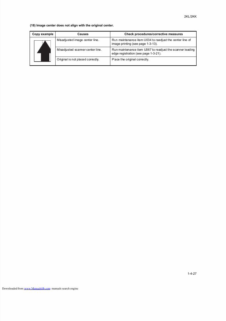
8/18/2019 taskalfa_220
http://slidepdf.com/reader/full/taskalfa220 135/300
2KL/2KK
1-4-27
(18) Image center does not align with the original center.
Copy example Causes Check procedures/corrective measures
Misadjusted image center line. Run maintenance item U034 to readjust the center line of
image printing (see page 1-3-13).
Misadjusted scanner center line. Run maintenance item U067 to readjust the scanner leading
edge registration (see page 1-3-21).
Original is not placed correctly. Place the original correctly.
loaded from www.Manualslib.com manuals search engine
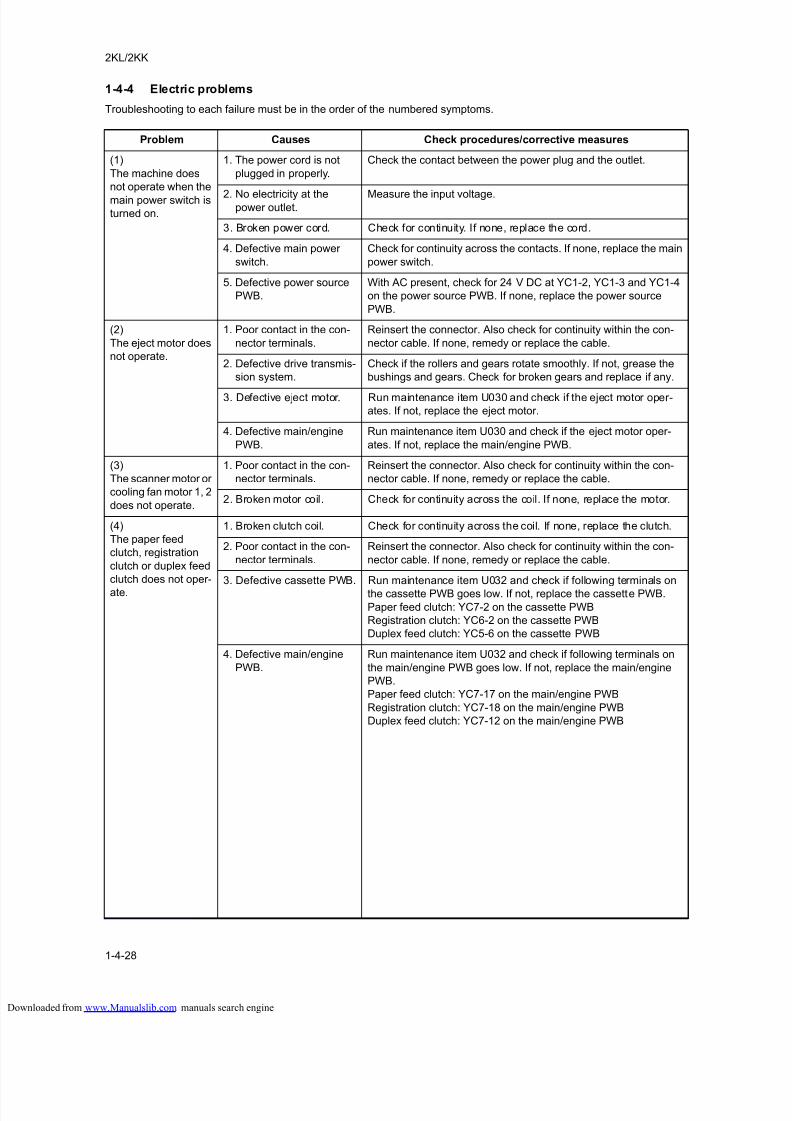
8/18/2019 taskalfa_220
http://slidepdf.com/reader/full/taskalfa220 136/300
2KL/2KK
1-4-28
1-4-4 Electric problems
Troubleshooting to each failure must be in the order of the numbered symptoms.
Problem Causes Check procedures/corrective measures
(1)
The machine does
not operate when the
main power switch isturned on.
1. The power cord is not
plugged in properly.
Check the contact between the power plug and the outlet.
2. No electricity at thepower outlet.
Measure the input voltage.
3. Broken power cord. Check for continuity. If none, replace the cord.
4. Defective main power
switch.
Check for continuity across the contacts. If none, replace the main
power switch.
5. Defective power source
PWB.
With AC present, check for 24 V DC at YC1-2, YC1-3 and YC1-4
on the power source PWB. If none, replace the power source
PWB.
(2)
The eject motor does
not operate.
1. Poor contact in the con-
nector terminals.
Reinsert the connector. Also check for continuity within the con-
nector cable. If none, remedy or replace the cable.
2. Defective drive transmis-
sion system.
Check if the rollers and gears rotate smoothly. If not, grease the
bushings and gears. Check for broken gears and replace if any.
3. Defective eject motor. Run maintenance item U030 and check if the eject motor oper-
ates. If not, replace the eject motor.
4. Defective main/engine
PWB.
Run maintenance item U030 and check if the eject motor oper-
ates. If not, replace the main/engine PWB.
(3)
The scanner motor or
cooling fan motor 1, 2
does not operate.
1. Poor contact in the con-
nector terminals.
Reinsert the connector. Also check for continuity within the con-
nector cable. If none, remedy or replace the cable.
2. Broken motor coil. Check for continuity across the coil. If none, replace the motor.
(4)
The paper feed
clutch, registration
clutch or duplex feed
clutch does not oper-
ate.
1. Broken clutch coil. Check for continuity across the coil. If none, replace the clutch.
2. Poor contact in the con-
nector terminals.
Reinsert the connector. Also check for continuity within the con-
nector cable. If none, remedy or replace the cable.
3. Defective cassette PWB. Run maintenance item U032 and check if following terminals on
the cassette PWB goes low. If not, replace the cassette PWB.
Paper feed clutch: YC7-2 on the cassette PWB
Registration clutch: YC6-2 on the cassette PWB
Duplex feed clutch: YC5-6 on the cassette PWB
4. Defective main/engine
PWB.
Run maintenance item U032 and check if following terminals on
the main/engine PWB goes low. If not, replace the main/engine
PWB.
Paper feed clutch: YC7-17 on the main/engine PWB
Registration clutch: YC7-18 on the main/engine PWB
Duplex feed clutch: YC7-12 on the main/engine PWB
loaded from www.Manualslib.com manuals search engine
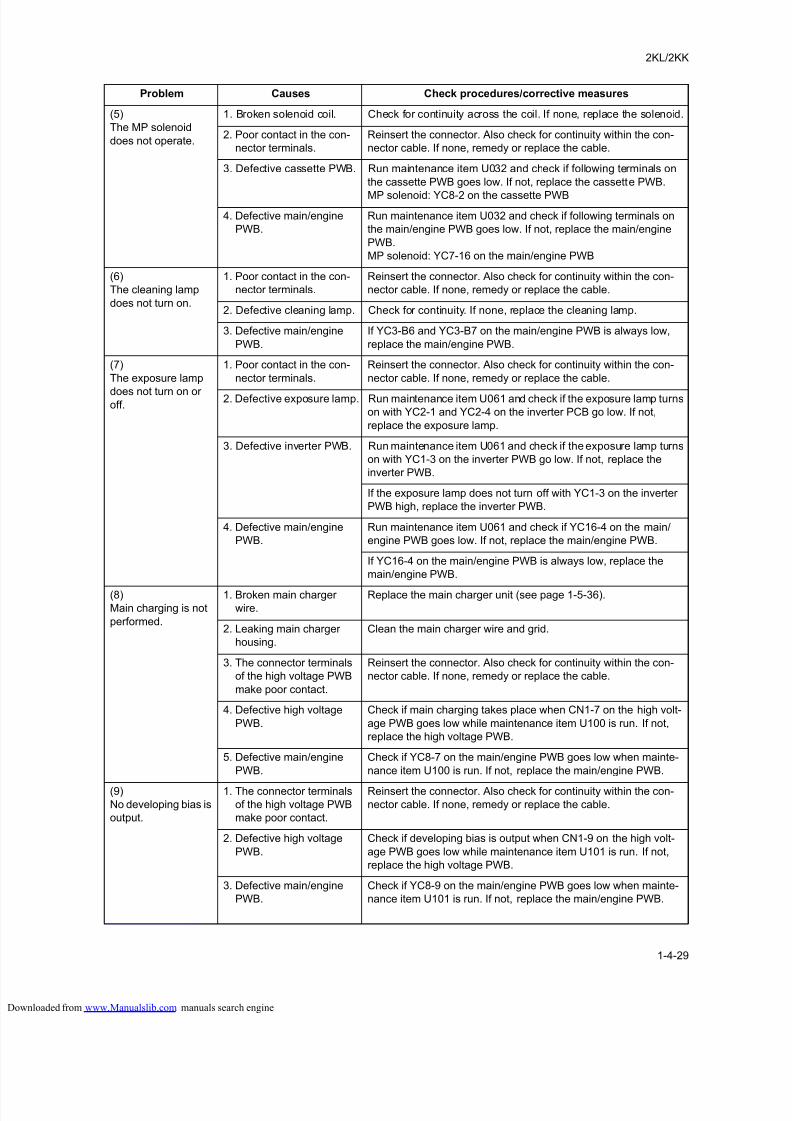
8/18/2019 taskalfa_220
http://slidepdf.com/reader/full/taskalfa220 137/300
2KL/2KK
1-4-29
(5)
The MP solenoid
does not operate.
1. Broken solenoid coil. Check for continuity across the coil. If none, replace the solenoid.
2. Poor contact in the con-
nector terminals.
Reinsert the connector. Also check for continuity within the con-
nector cable. If none, remedy or replace the cable.
3. Defective cassette PWB. Run maintenance item U032 and check if following terminals on
the cassette PWB goes low. If not, replace the cassette PWB.
MP solenoid: YC8-2 on the cassette PWB
4. Defective main/engine
PWB.
Run maintenance item U032 and check if following terminals on
the main/engine PWB goes low. If not, replace the main/engine
PWB.
MP solenoid: YC7-16 on the main/engine PWB
(6)
The cleaning lamp
does not turn on.
1. Poor contact in the con-
nector terminals.
Reinsert the connector. Also check for continuity within the con-
nector cable. If none, remedy or replace the cable.
2. Defective cleaning lamp. Check for continuity. If none, replace the cleaning lamp.
3. Defective main/engine
PWB.
If YC3-B6 and YC3-B7 on the main/engine PWB is always low,
replace the main/engine PWB.
(7)
The exposure lamp
does not turn on oroff.
1. Poor contact in the con-
nector terminals.
Reinsert the connector. Also check for continuity within the con-
nector cable. If none, remedy or replace the cable.
2. Defective exposure lamp. Run maintenance item U061 and check if the exposure lamp turns
on with YC2-1 and YC2-4 on the inverter PCB go low. If not,
replace the exposure lamp.
3. Defective inverter PWB. Run maintenance item U061 and check if the exposure lamp turns
on with YC1-3 on the inverter PWB go low. If not, replace the
inverter PWB.
If the exposure lamp does not turn off with YC1-3 on the inverter
PWB high, replace the inverter PWB.
4. Defective main/engine
PWB.
Run maintenance item U061 and check if YC16-4 on the main/
engine PWB goes low. If not, replace the main/engine PWB.
If YC16-4 on the main/engine PWB is always low, replace the
main/engine PWB.
(8)
Main charging is not
performed.
1. Broken main charger
wire.
Replace the main charger unit (see page 1-5-36).
2. Leaking main charger
housing.
Clean the main charger wire and grid.
3. The connector terminals
of the high voltage PWB
make poor contact.
Reinsert the connector. Also check for continuity within the con-
nector cable. If none, remedy or replace the cable.
4. Defective high voltage
PWB.
Check if main charging takes place when CN1-7 on the high volt-
age PWB goes low while maintenance item U100 is run. If not,
replace the high voltage PWB.
5. Defective main/engine
PWB.
Check if YC8-7 on the main/engine PWB goes low when mainte-
nance item U100 is run. If not, replace the main/engine PWB.
(9)
No developing bias is
output.
1. The connector terminals
of the high voltage PWB
make poor contact.
Reinsert the connector. Also check for continuity within the con-
nector cable. If none, remedy or replace the cable.
2. Defective high voltage
PWB.
Check if developing bias is output when CN1-9 on the high volt-
age PWB goes low while maintenance item U101 is run. If not,
replace the high voltage PWB.
3. Defective main/engine
PWB.
Check if YC8-9 on the main/engine PWB goes low when mainte-
nance item U101 is run. If not, replace the main/engine PWB.
Problem Causes Check procedures/corrective measures
loaded from www.Manualslib.com manuals search engine
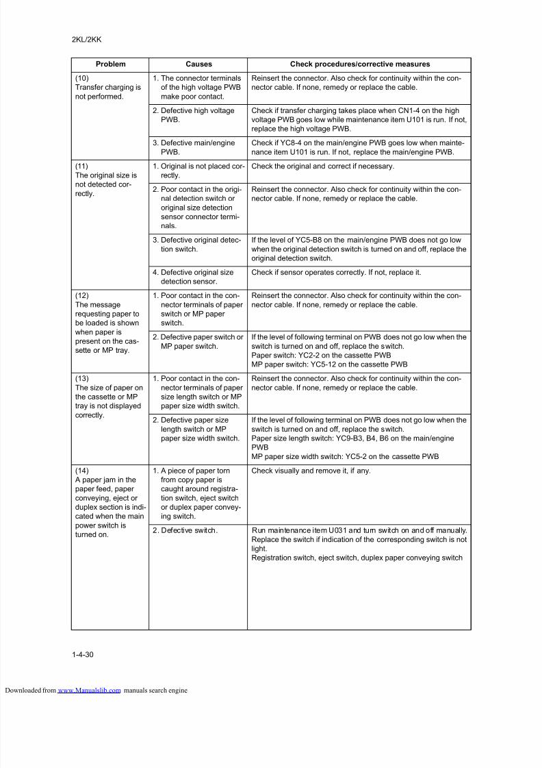
8/18/2019 taskalfa_220
http://slidepdf.com/reader/full/taskalfa220 138/300
2KL/2KK
1-4-30
(10)
Transfer charging is
not performed.
1. The connector terminals
of the high voltage PWB
make poor contact.
Reinsert the connector. Also check for continuity within the con-
nector cable. If none, remedy or replace the cable.
2. Defective high voltage
PWB.
Check if transfer charging takes place when CN1-4 on the high
voltage PWB goes low while maintenance item U101 is run. If not,
replace the high voltage PWB.
3. Defective main/engine
PWB.
Check if YC8-4 on the main/engine PWB goes low when mainte-
nance item U101 is run. If not, replace the main/engine PWB.
(11)
The original size is
not detected cor-
rectly.
1. Original is not placed cor-
rectly.
Check the original and correct if necessary.
2. Poor contact in the origi-
nal detection switch or
original size detection
sensor connector termi-
nals.
Reinsert the connector. Also check for continuity within the con-
nector cable. If none, remedy or replace the cable.
3. Defective original detec-
tion switch.
If the level of YC5-B8 on the main/engine PWB does not go low
when the original detection switch is turned on and off, replace the
original detection switch.
4. Defective original size
detection sensor.
Check if sensor operates correctly. If not, replace it.
(12)
The message
requesting paper to
be loaded is shown
when paper is
present on the cas-
sette or MP tray.
1. Poor contact in the con-
nector terminals of paper
switch or MP paper
switch.
Reinsert the connector. Also check for continuity within the con-
nector cable. If none, remedy or replace the cable.
2. Defective paper switch or
MP paper switch.
If the level of following terminal on PWB does not go low when the
switch is turned on and off, replace the switch.
Paper switch: YC2-2 on the cassette PWB
MP paper switch: YC5-12 on the cassette PWB
(13)
The size of paper on
the cassette or MP
tray is not displayedcorrectly.
1. Poor contact in the con-
nector terminals of paper
size length switch or MP
paper size width switch.
Reinsert the connector. Also check for continuity within the con-
nector cable. If none, remedy or replace the cable.
2. Defective paper size
length switch or MP
paper size width switch.
If the level of following terminal on PWB does not go low when the
switch is turned on and off, replace the switch.
Paper size length switch: YC9-B3, B4, B6 on the main/engine
PWB
MP paper size width switch: YC5-2 on the cassette PWB
(14)
A paper jam in the
paper feed, paper
conveying, eject or
duplex section is indi-
cated when the main
power switch is
turned on.
1. A piece of paper torn
from copy paper is
caught around registra-
tion switch, eject switch
or duplex paper convey-
ing switch.
Check visually and remove it, if any.
2. Defective switch. Run maintenance item U031 and turn switch on and off manually.
Replace the switch if indication of the corresponding switch is notlight.
Registration switch, eject switch, duplex paper conveying switch
Problem Causes Check procedures/corrective measures
loaded from www.Manualslib.com manuals search engine
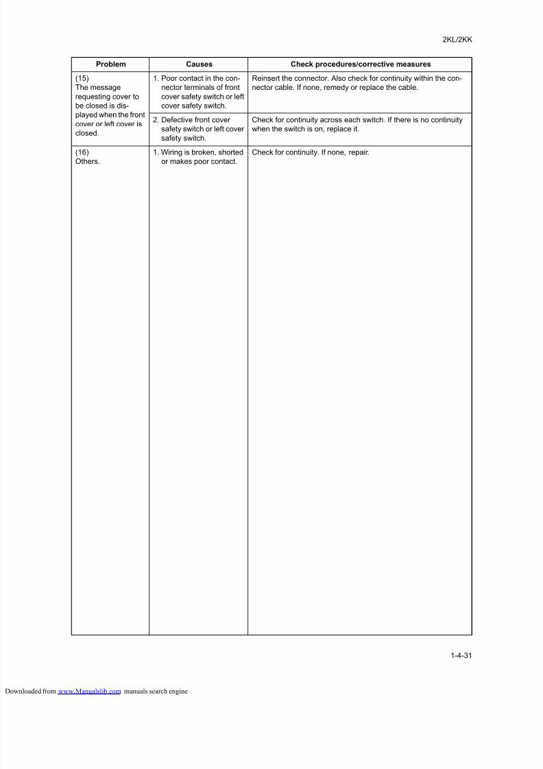
8/18/2019 taskalfa_220
http://slidepdf.com/reader/full/taskalfa220 139/300
2KL/2KK
1-4-31
(15)
The message
requesting cover to
be closed is dis-
played when the front
cover or left cover is
closed.
1. Poor contact in the con-
nector terminals of front
cover safety switch or left
cover safety switch.
Reinsert the connector. Also check for continuity within the con-
nector cable. If none, remedy or replace the cable.
2. Defective front cover
safety switch or left cover
safety switch.
Check for continuity across each switch. If there is no continuity
when the switch is on, replace it.
(16)
Others.
1. Wiring is broken, shorted
or makes poor contact.
Check for continuity. If none, repair.
Problem Causes Check procedures/corrective measures
loaded from www.Manualslib.com manuals search engine
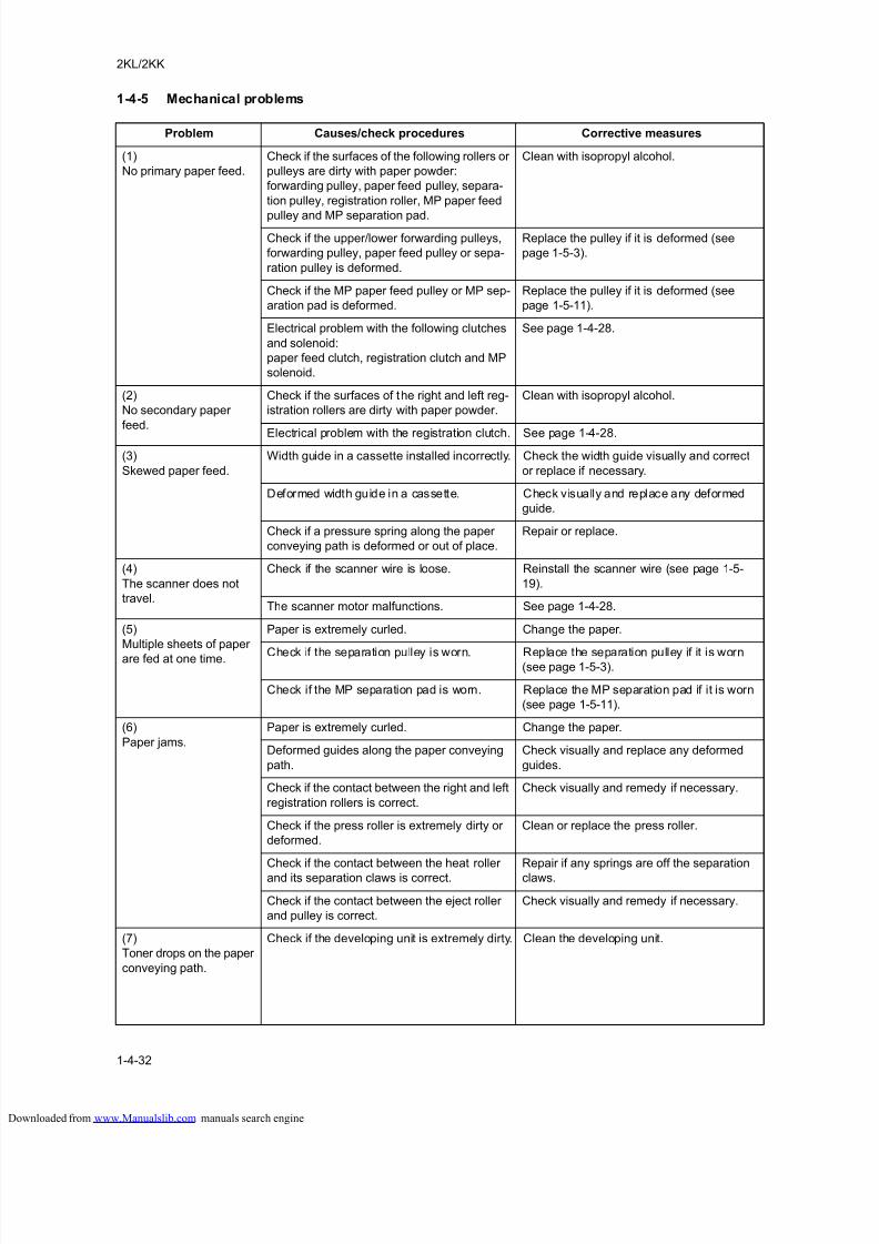
8/18/2019 taskalfa_220
http://slidepdf.com/reader/full/taskalfa220 140/300
2KL/2KK
1-4-32
1-4-5 Mechanical problems
Problem Causes/check procedures Corrective measures
(1)
No primary paper feed.
Check if the surfaces of the following rollers or
pulleys are dirty with paper powder:
forwarding pulley, paper feed pulley, separa-
tion pulley, registration roller, MP paper feed
pulley and MP separation pad.
Clean with isopropyl alcohol.
Check if the upper/lower forwarding pulleys,
forwarding pulley, paper feed pulley or sepa-
ration pulley is deformed.
Replace the pulley if it is deformed (see
page 1-5-3).
Check if the MP paper feed pulley or MP sep-
aration pad is deformed.
Replace the pulley if it is deformed (see
page 1-5-11).
Electrical problem with the following clutches
and solenoid:
paper feed clutch, registration clutch and MP
solenoid.
See page 1-4-28.
(2)
No secondary paper
feed.
Check if the surfaces of the right and left reg-
istration rollers are dirty with paper powder.
Clean with isopropyl alcohol.
Electrical problem with the registration clutch. See page 1-4-28.
(3)
Skewed paper feed.
Width guide in a cassette installed incorrectly. Check the width guide visually and correct
or replace if necessary.
Deformed width guide in a cassette. Check visually and replace any deformed
guide.
Check if a pressure spring along the paper
conveying path is deformed or out of place.
Repair or replace.
(4)
The scanner does not
travel.
Check if the scanner wire is loose. Reinstall the scanner wire (see page 1-5-
19).
The scanner motor malfunctions. See page 1-4-28.
(5)
Multiple sheets of paper
are fed at one time.
Paper is extremely curled. Change the paper.
Check if the separation pulley is worn. Replace the separation pulley if it is worn(see page 1-5-3).
Check if the MP separation pad is worn. Replace the MP separation pad if it is worn
(see page 1-5-11).
(6)
Paper jams.
Paper is extremely curled. Change the paper.
Deformed guides along the paper conveying
path.
Check visually and replace any deformed
guides.
Check if the contact between the right and left
registration rollers is correct.
Check visually and remedy if necessary.
Check if the press roller is extremely dirty or
deformed.
Clean or replace the press roller.
Check if the contact between the heat roller
and its separation claws is correct.
Repair if any springs are off the separation
claws.
Check if the contact between the eject roller
and pulley is correct.
Check visually and remedy if necessary.
(7)
Toner drops on the paper
conveying path.
Check if the developing unit is extremely dirty. Clean the developing unit.
loaded from www.Manualslib.com manuals search engine
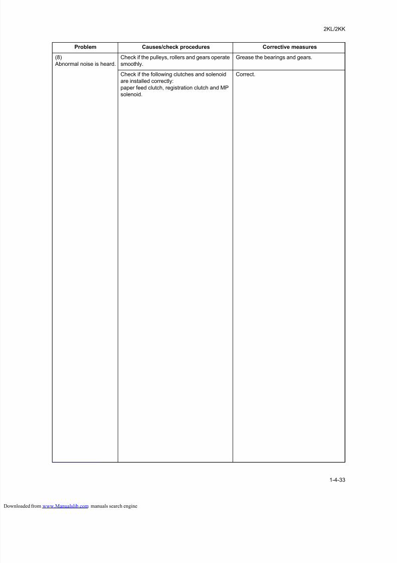
8/18/2019 taskalfa_220
http://slidepdf.com/reader/full/taskalfa220 141/300
2KL/2KK
1-4-33
(8)
Abnormal noise is heard.
Check if the pulleys, rollers and gears operate
smoothly.
Grease the bearings and gears.
Check if the following clutches and solenoid
are installed correctly:
paper feed clutch, registration clutch and MP
solenoid.
Correct.
Problem Causes/check procedures Corrective measures
loaded from www.Manualslib.com manuals search engine

8/18/2019 taskalfa_220
http://slidepdf.com/reader/full/taskalfa220 142/300
8/18/2019 taskalfa_220
http://slidepdf.com/reader/full/taskalfa220 143/300
2KL/2KK
1-5-1
1-5 Assemblyand Disassembly
1-5-1 Precautions for assembly and disassembly
(1) Precautions
Before starting disassembly, turning off the main power switch. And then unplug the power cable from the wall outlet.
When handling PWBs (printed wiring boards), do not touch parts with bare hands.
The PWBs are susceptible to static charge.
Do not touch any PWB containing ICs with bare hands or any object prone to static charge.
Use only the specified parts to replace the fuser unit thermostat. Never substitute electric wires, as the machine may beseriously damaged.
When removing the hook of the connector, be sure to release the hook.
Take care not to get the cables caught.
To reassemble the parts, use the original screws. If the types and the sizes of screws are not known, refer to the PARTS
LIST.
(2) Drum
Note the following when handling or storing the drum.
When removing the drum unit, never expose the drum surface to strong direct light.
Keep the drum at an ambient temperature between -20°C/-4°F and 40°C/104°F and at a relative humidity not higher than
90% RH. Avoid abrupt changes in temperature and humidity.
Avoid exposure to any substance which is harmful to or may affect the quality of the drum.
Do not touch the drum surface with any object. Should it be touched by hands or stained with oil, clean it.
(3) Toner
Store the toner container in a cool, dark place.
Avoid direct light and high humidity.
loaded from www.Manualslib.com manuals search engine
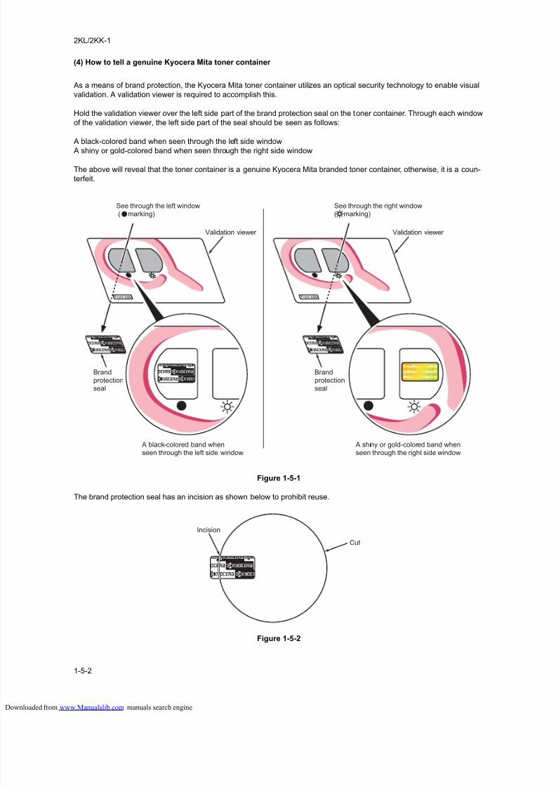
8/18/2019 taskalfa_220
http://slidepdf.com/reader/full/taskalfa220 144/300
2KL/2KK-1
1-5-2
(4) How to tell a genuine Kyocera Mita toner container
As a means of brand protection, the Kyocera Mita toner container utilizes an optical security technology to enable visual
validation. A validation viewer is required to accomplish this.
Hold the validation viewer over the left side part of the brand protection seal on the toner container. Through each window
of the validation viewer, the left side part of the seal should be seen as follows:
A black-colored band when seen through the left side window
A shiny or gold-colored band when seen through the right side window
The above will reveal that the toner container is a genuine Kyocera Mita branded toner container, otherwise, it is a coun-
terfeit.
Figure 1-5-1
The brand protection seal has an incision as shown below to prohibit reuse.
Figure 1-5-2
Validation viewer Validation viewer
Brandprotectionseal
Brandprotectionseal
See through the left window ( marking)
See through the right window( marking)
A shiny or gold-colored band whenseen through the right side window
A black-colored band whenseen through the left side window
Incision
Cut
loaded from www.Manualslib.com manuals search engine
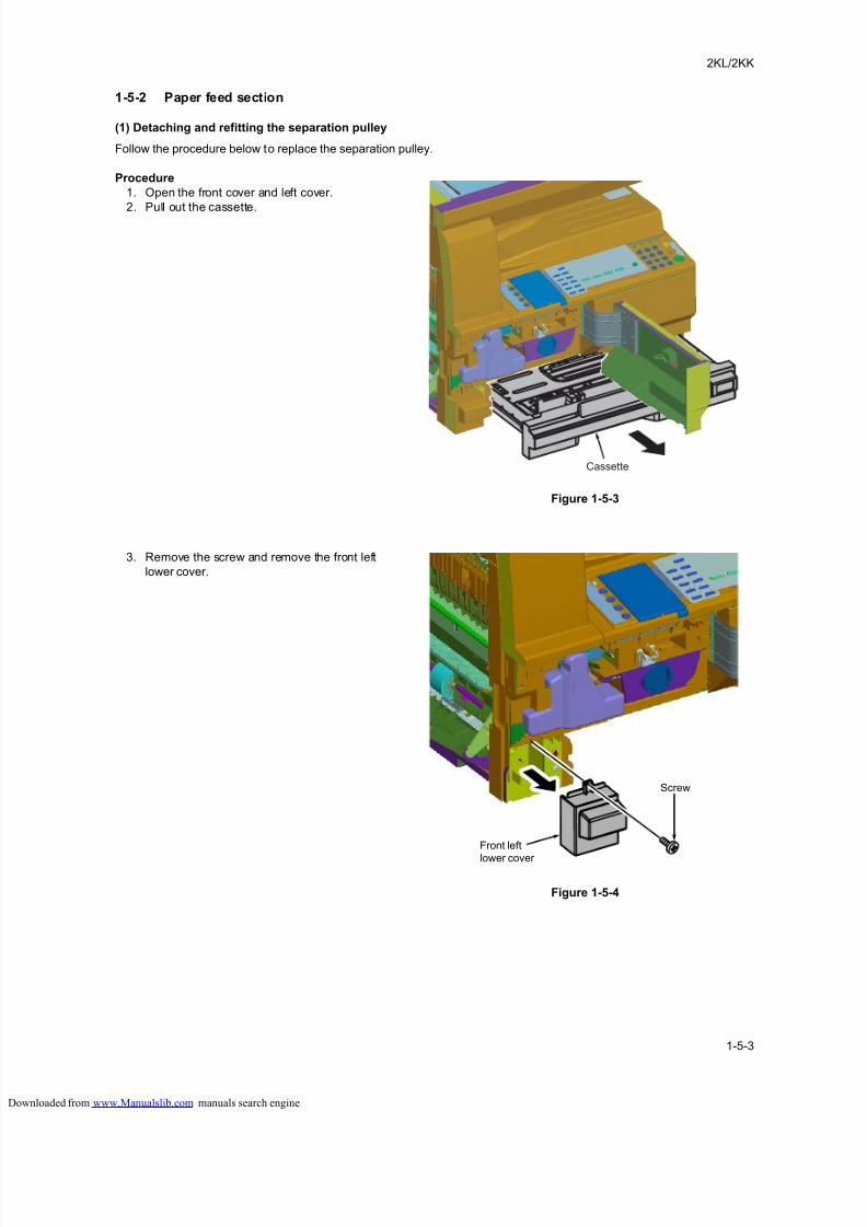
8/18/2019 taskalfa_220
http://slidepdf.com/reader/full/taskalfa220 145/300
2KL/2KK
1-5-3
1-5-2 Paper feed section
(1) Detaching and refitting the separation pulley
Follow the procedure below to replace the separation pulley.
Procedure
1. Open the front cover and left cover.
2. Pull out the cassette.
Figure 1-5-3
3. Remove the screw and remove the front left
lower cover.
Figure 1-5-4
Cassette
Screw
Front left
lower cover
loaded from www.Manualslib.com manuals search engine
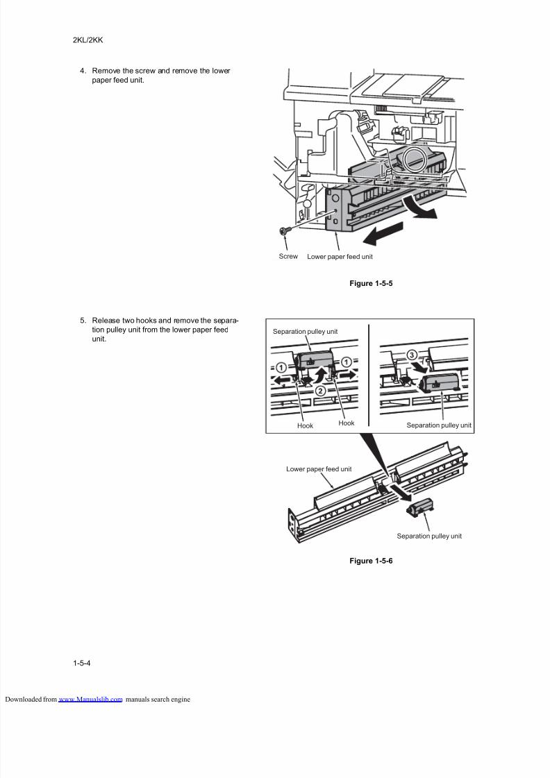
8/18/2019 taskalfa_220
http://slidepdf.com/reader/full/taskalfa220 146/300
2KL/2KK
1-5-4
4. Remove the screw and remove the lower
paper feed unit.
Figure 1-5-5
5. Release two hooks and remove the separa-
tion pulley unit from the lower paper feed
unit.
Figure 1-5-6
Screw Lower paper feed unit
Hook Hook
Separation pulley unit
Separation pulley unit
Separation pulley unit
Lower paper feed unit
loaded from www.Manualslib.com manuals search engine
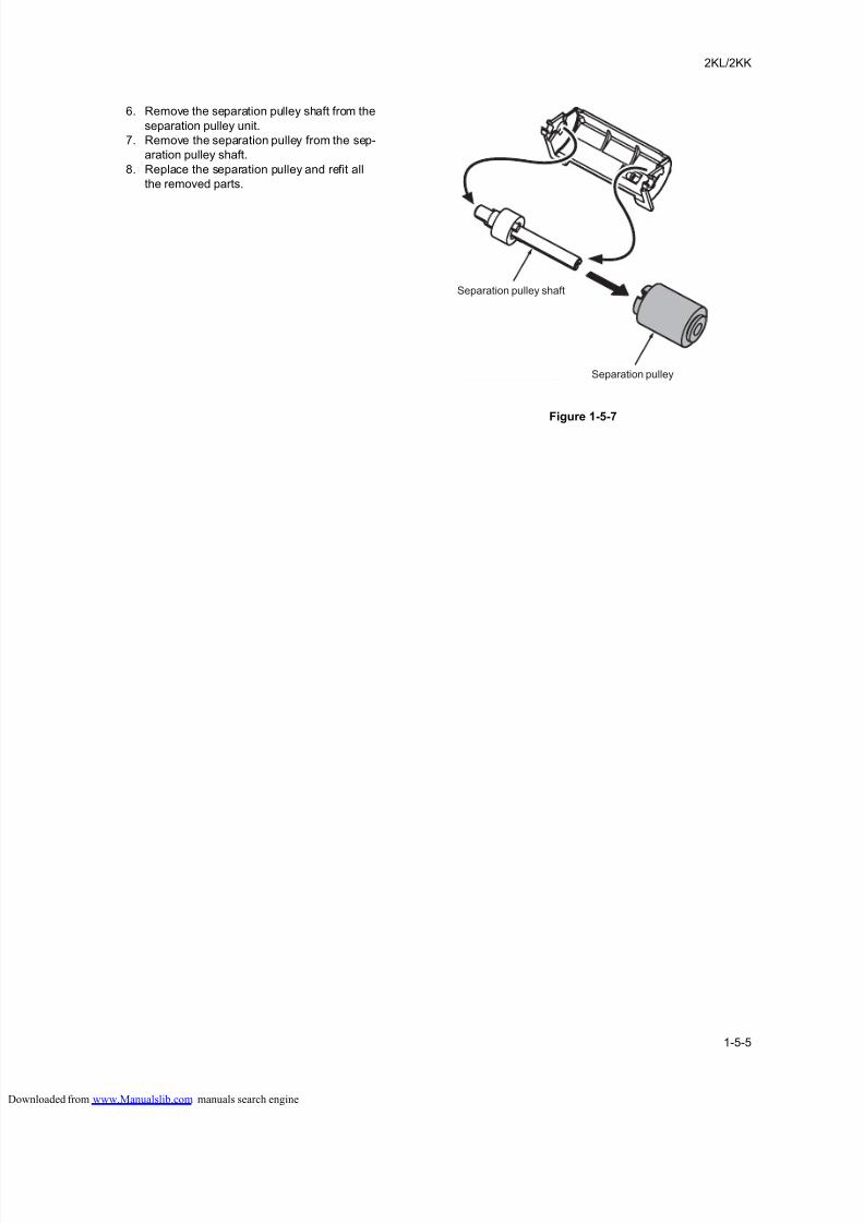
8/18/2019 taskalfa_220
http://slidepdf.com/reader/full/taskalfa220 147/300
2KL/2KK
1-5-5
6. Remove the separation pulley shaft from the
separation pulley unit.
7. Remove the separation pulley from the sep-
aration pulley shaft.
8. Replace the separation pulley and refit all
the removed parts.
Figure 1-5-7
Separation pulley
Separation pulley shaft
loaded from www.Manualslib.com manuals search engine
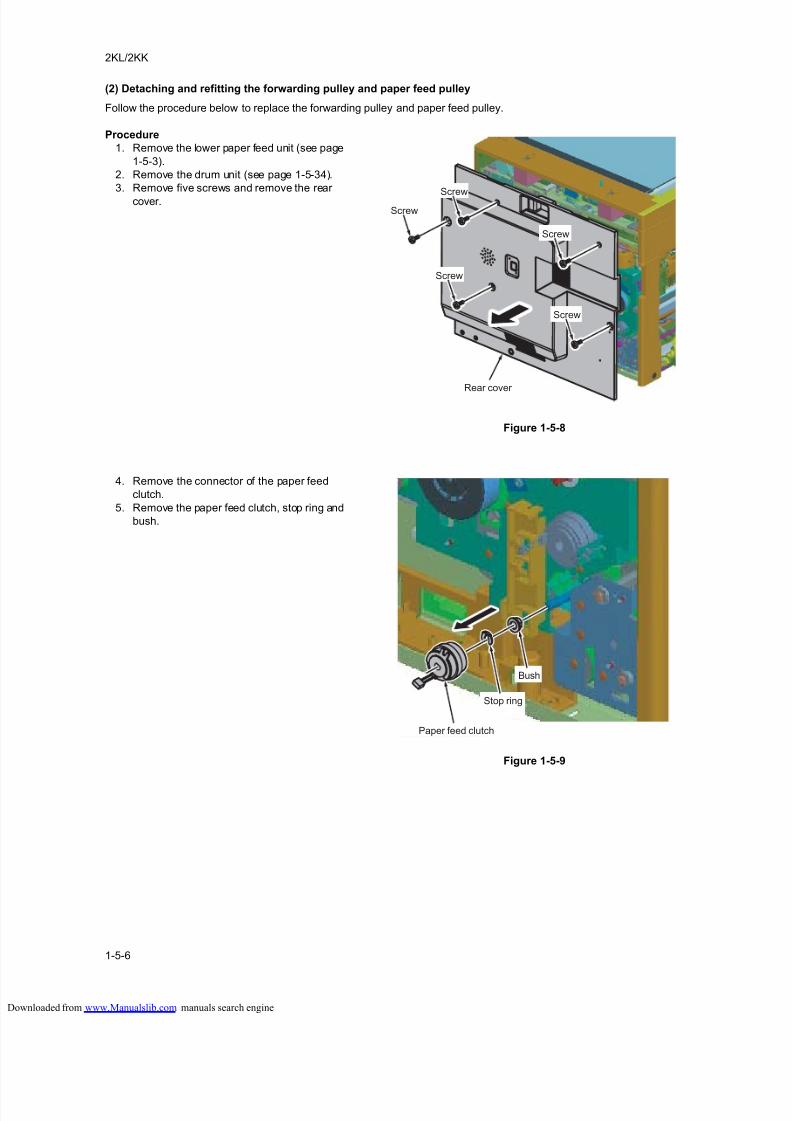
8/18/2019 taskalfa_220
http://slidepdf.com/reader/full/taskalfa220 148/300
2KL/2KK
1-5-6
(2) Detaching and refitting the forwarding pulley and paper feed pulley
Follow the procedure below to replace the forwarding pulley and paper feed pulley.
Procedure
1. Remove the lower paper feed unit (see page
1-5-3).
2. Remove the drum unit (see page 1-5-34).
3. Remove five screws and remove the rear
cover.
Figure 1-5-8
4. Remove the connector of the paper feed
clutch.
5. Remove the paper feed clutch, stop ring and
bush.
Figure 1-5-9
ScrewScrew
Screw
Screw
Screw
Rear cover
Paper feed clutch
Stop ring
Bush
loaded from www.Manualslib.com manuals search engine
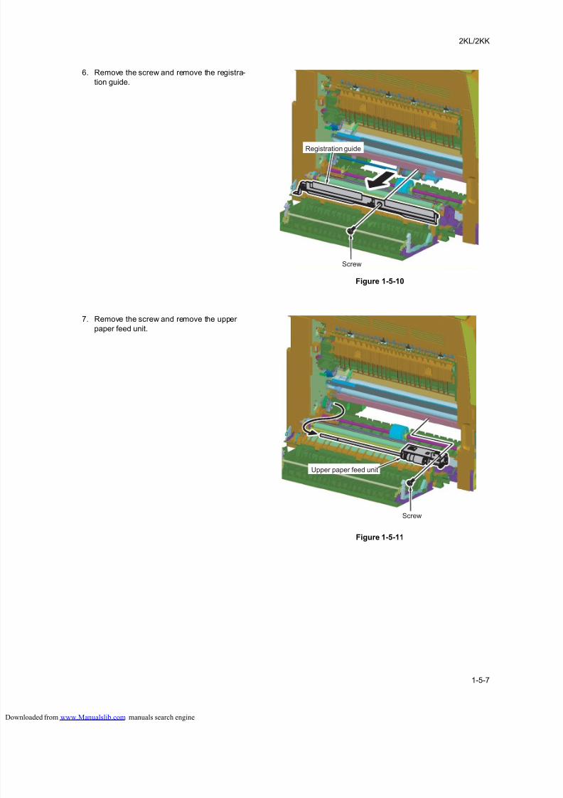
8/18/2019 taskalfa_220
http://slidepdf.com/reader/full/taskalfa220 149/300
2KL/2KK
1-5-7
6. Remove the screw and remove the registra-
tion guide.
Figure 1-5-10
7. Remove the screw and remove the upper
paper feed unit.
Figure 1-5-11
Screw
Registration guide
Screw
Upper paper feed unit
loaded from www.Manualslib.com manuals search engine
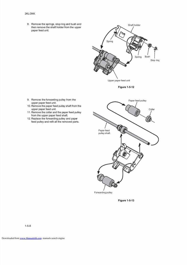
8/18/2019 taskalfa_220
http://slidepdf.com/reader/full/taskalfa220 150/300
2KL/2KK
1-5-8
8. Remove the springs, stop ring and bush and
then remove the shaft holder from the upper
paper feed unit.
Figure 1-5-12
9. Remove the forwarding pulley from the
upper paper feed unit.
10. Remove the paper feed pulley shaft from the
upper paper feed unit.
11. Remove the collar and the paper feed pulley
from the upper paper feed shaft.
12. Replace the forwarding pulley and paper
feed pulley and refit all the removed parts.
Figure 1-5-13
Upper paper feed unit
Stop ring
BushSpring
Spring
Shaft holder
Forwarding pulley
Paper feedpulley shaft
Paper feed pulley
Collar
loaded from www.Manualslib.com manuals search engine
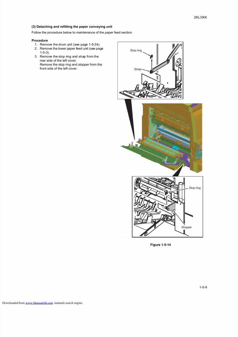
8/18/2019 taskalfa_220
http://slidepdf.com/reader/full/taskalfa220 151/300
2KL/2KK
1-5-9
(3) Detaching and refitting the paper conveying unit
Follow the procedure below to maintenance of the paper feed section.
Procedure
1. Remove the drum unit (see page 1-5-34).
2. Remove the lower paper feed unit (see page
1-5-3).
3. Remove the stop ring and strap from the
rear side of the left cover.
Remove the stop ring and stopper from the
front side of the left cover.
Figure 1-5-14
Stopper
Stop ring
Strap
Stop ring
loaded from www.Manualslib.com manuals search engine
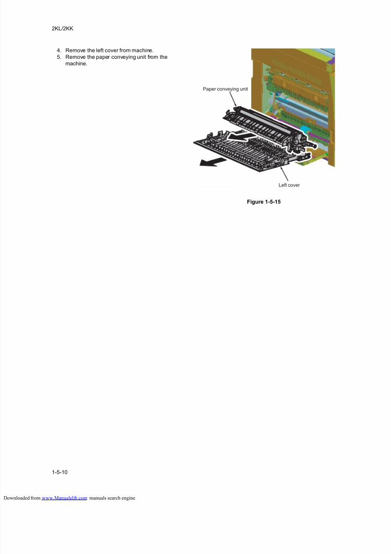
8/18/2019 taskalfa_220
http://slidepdf.com/reader/full/taskalfa220 152/300
2KL/2KK
1-5-10
4. Remove the left cover from machine.
5. Remove the paper conveying unit from the
machine.
Figure 1-5-15
Left cover
Paper conveying unit
loaded from www.Manualslib.com manuals search engine
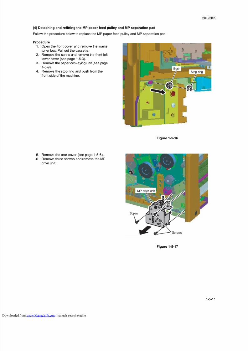
8/18/2019 taskalfa_220
http://slidepdf.com/reader/full/taskalfa220 153/300
2KL/2KK
1-5-11
(4) Detaching and refitting the MP paper feed pulley and MP separation pad
Follow the procedure below to replace the MP paper feed pulley and MP separation pad.
Procedure
1. Open the front cover and remove the waste
toner box. Pull out the cassette.
2. Remove the screw and remove the front left
lower cover (see page 1-5-3).
3. Remove the paper conveying unit (see page
1-5-9).
4. Remove the stop ring and bush from the
front side of the machine.
Figure 1-5-16
5. Remove the rear cover (see page 1-5-6).
6. Remove three screws and remove the MP
drive unit.
Figure 1-5-17
BushStop ring
Screw
Screws
MP drive unit
loaded from www.Manualslib.com manuals search engine
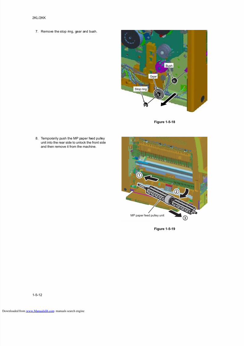
8/18/2019 taskalfa_220
http://slidepdf.com/reader/full/taskalfa220 154/300
2KL/2KK
1-5-12
7. Remove the stop ring, gear and bush.
Figure 1-5-18
8. Temporarily push the MP paper feed pulley
unit into the rear side to unlock the front side
and then remove it from the machine.
Figure 1-5-19
Bush
Gear
Stop ring
MP paper feed pulley unit
loaded from www.Manualslib.com manuals search engine
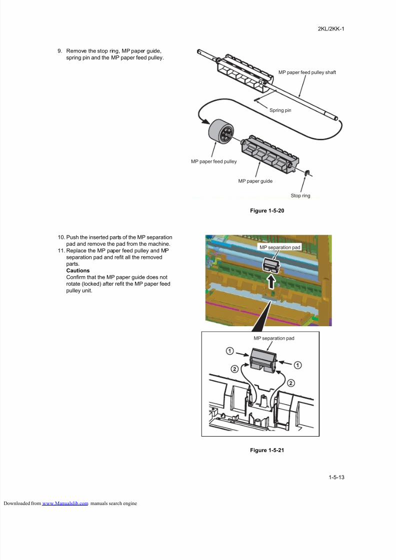
8/18/2019 taskalfa_220
http://slidepdf.com/reader/full/taskalfa220 155/300
2KL/2KK-1
1-5-13
9. Remove the stop ring, MP paper guide,
spring pin and the MP paper feed pulley.
Figure 1-5-20
10. Push the inserted parts of the MP separation
pad and remove the pad from the machine.
11. Replace the MP paper feed pulley and MP
separation pad and refit all the removed
parts.
Cautions
Confirm that the MP paper guide does not
rotate (locked) after refit the MP paper feed
pulley unit.
Figure 1-5-21
MP paper guide
Stop ring
MP paper feed pulley
Spring pin
MP paper feed pulley shaft
MP separation pad
MP separation pad
loaded from www.Manualslib.com manuals search engine
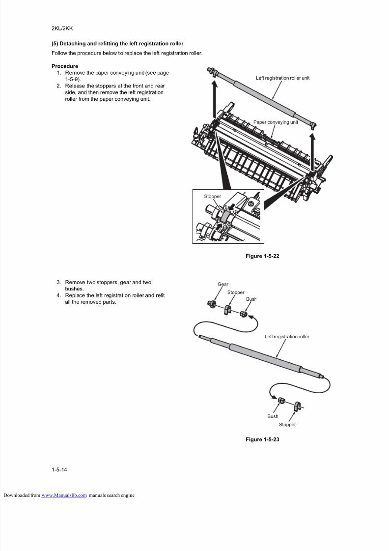
8/18/2019 taskalfa_220
http://slidepdf.com/reader/full/taskalfa220 156/300
2KL/2KK
1-5-14
(5) Detaching and refitting the left registration roller
Follow the procedure below to replace the left registration roller.
Procedure
1. Remove the paper conveying unit (see page
1-5-9).
2. Release the stoppers at the front and rear
side, and then remove the left registration
roller from the paper conveying unit.
Figure 1-5-22
3. Remove two stoppers, gear and two
bushes.4. Replace the left registration roller and refit
all the removed parts.
Figure 1-5-23
Left registration roller unit
Paper conveying unit
Stopper
Left registration roller
Stopper
Stopper
Bush
Bush
Gear
loaded from www.Manualslib.com manuals search engine
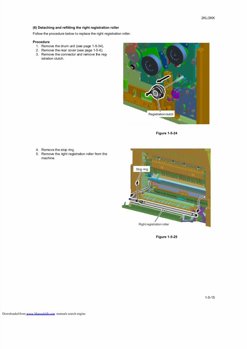
8/18/2019 taskalfa_220
http://slidepdf.com/reader/full/taskalfa220 157/300
2KL/2KK
1-5-15
(6) Detaching and refitting the right registration roller
Follow the procedure below to replace the right registration roller.
Procedure
1. Remove the drum unit (see page 1-5-34).
2. Remove the rear cover (see page 1-5-6).
3. Remove the connector and remove the reg-
istration clutch.
Figure 1-5-24
4. Remove the stop ring.
5. Remove the right registration roller from the
machine.
Figure 1-5-25
Registration clutch
Right registration roller
Stop ring
loaded from www.Manualslib.com manuals search engine
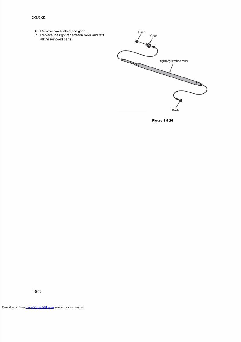
8/18/2019 taskalfa_220
http://slidepdf.com/reader/full/taskalfa220 158/300
2KL/2KK
1-5-16
6. Remove two bushes and gear.
7. Replace the right registration roller and refit
all the removed parts.
Figure 1-5-26
Bush
Bush
Gear
Right registration roller
loaded from www.Manualslib.com manuals search engine
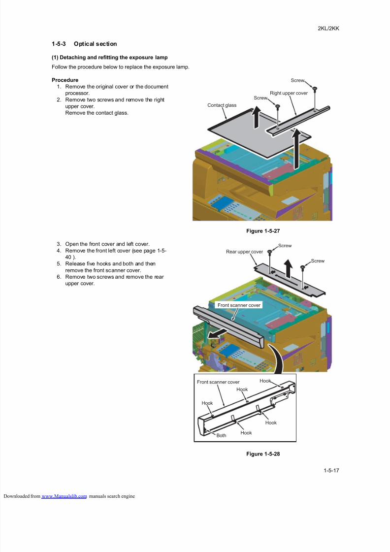
8/18/2019 taskalfa_220
http://slidepdf.com/reader/full/taskalfa220 159/300
2KL/2KK
1-5-17
1-5-3 Optical section
(1) Detaching and refitting the exposure lamp
Follow the procedure below to replace the exposure lamp.
Procedure
1. Remove the original cover or the document
processor.
2. Remove two screws and remove the right
upper cover.
Remove the contact glass.
Figure 1-5-27
3. Open the front cover and left cover.
4. Remove the front left cover (see page 1-5-
40 ).
5. Release five hooks and both and then
remove the front scanner cover.
6. Remove two screws and remove the rear
upper cover.
Figure 1-5-28
Right upper cover Screw
Screw
Contact glass
Screw
Rear upper cover
Front scanner cover
Hook
Hook
Front scanner cover
Hook
Hook
Hook
Both
Screw
loaded from www.Manualslib.com manuals search engine
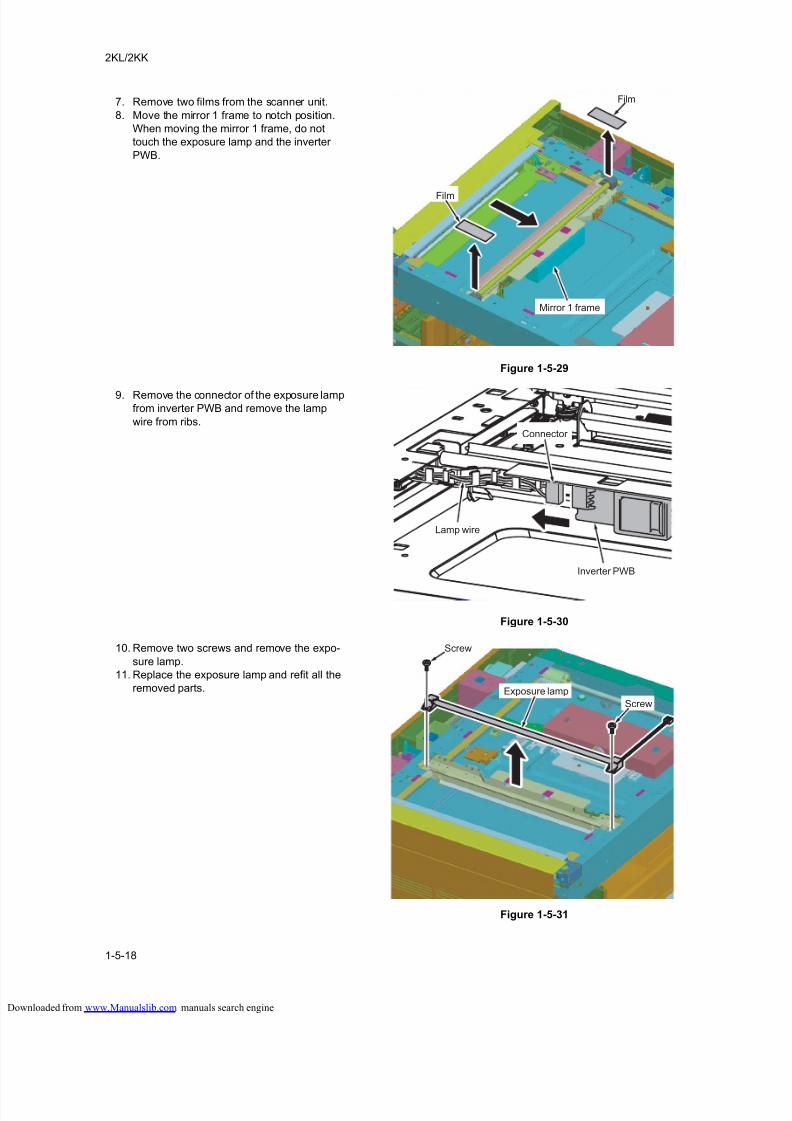
8/18/2019 taskalfa_220
http://slidepdf.com/reader/full/taskalfa220 160/300
2KL/2KK
1-5-18
7. Remove two films from the scanner unit.
8. Move the mirror 1 frame to notch position.
When moving the mirror 1 frame, do not
touch the exposure lamp and the inverter
PWB.
Figure 1-5-29
9. Remove the connector of the exposure lampfrom inverter PWB and remove the lamp
wire from ribs.
Figure 1-5-30
10. Remove two screws and remove the expo-
sure lamp.
11. Replace the exposure lamp and refit all the
removed parts.
Figure 1-5-31
Film
Film
Mirror 1 frame
Connector
Inverter PWB
Lamp wire
Screw
Screw
Exposure lamp
loaded from www.Manualslib.com manuals search engine
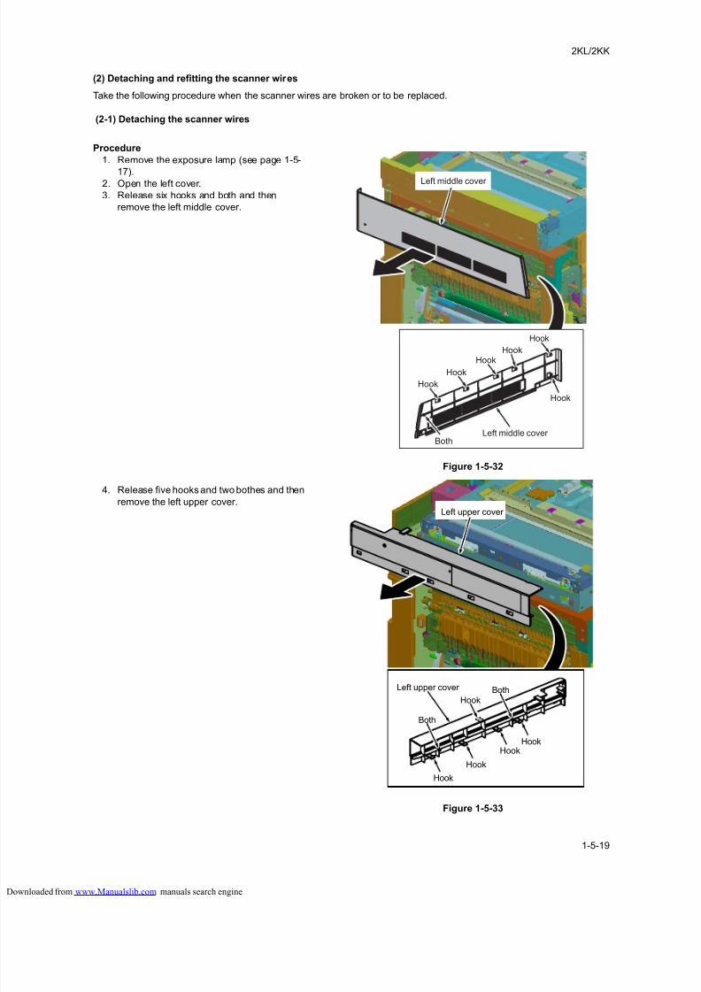
8/18/2019 taskalfa_220
http://slidepdf.com/reader/full/taskalfa220 161/300
2KL/2KK
1-5-19
(2) Detaching and refitting the scanner wires
Take the following procedure when the scanner wires are broken or to be replaced.
(2-1) Detaching the scanner wires
Procedure
1. Remove the exposure lamp (see page 1-5-
17).2. Open the left cover.
3. Release six hooks and both and then
remove the left middle cover.
Figure 1-5-32
4. Release five hooks and two bothes and then
remove the left upper cover.
Figure 1-5-33
Left middle cover
Hook
Hook
Left middle cover Both
HookHook
Hook
Hook
Left upper cover
Left upper cover
Hook
Hook
Both
Both
Hook
Hook
Hook
loaded from www.Manualslib.com manuals search engine
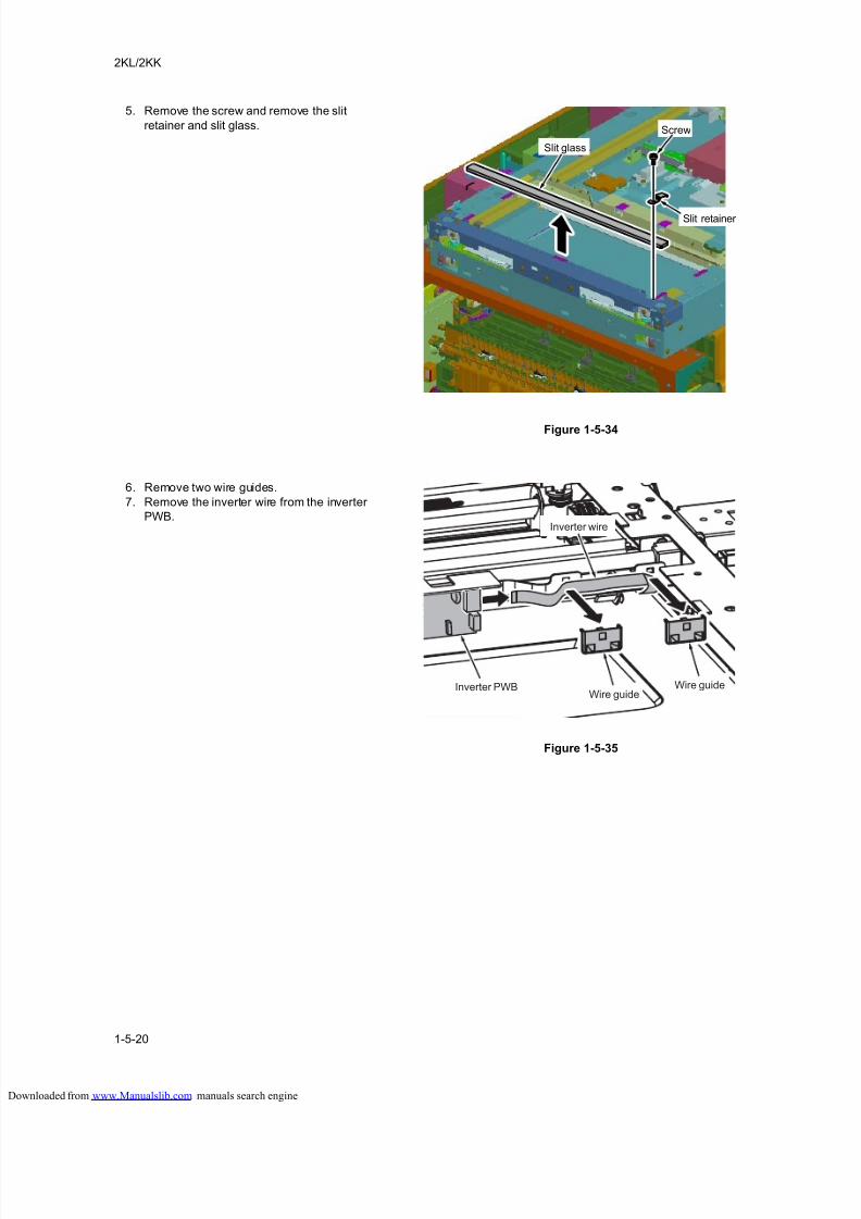
8/18/2019 taskalfa_220
http://slidepdf.com/reader/full/taskalfa220 162/300
2KL/2KK
1-5-20
5. Remove the screw and remove the slit
retainer and slit glass.
Figure 1-5-34
6. Remove two wire guides.
7. Remove the inverter wire from the inverter
PWB.
Figure 1-5-35
Screw
Slit retainer
Slit glass
Inverter PWBWire guide
Wire guide
Inverter wire
loaded from www.Manualslib.com manuals search engine
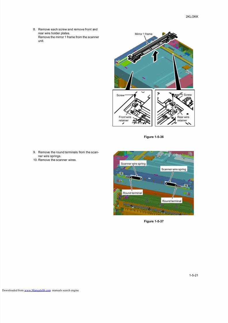
8/18/2019 taskalfa_220
http://slidepdf.com/reader/full/taskalfa220 163/300
2KL/2KK
1-5-21
8. Remove each screw and remove front and
rear wire holder plates.
Remove the mirror 1 frame from the scanner
unit.
Figure 1-5-36
9. Remove the round terminals from the scan-
ner wire springs.
10. Remove the scanner wires.
Figure 1-5-37
Screw Screw
Mirror 1 frame
Front wireretainer
Rear wireretainer
Scanner wire spring
Scanner wire spring
Round terminal
Round terminal
loaded from www.Manualslib.com manuals search engine
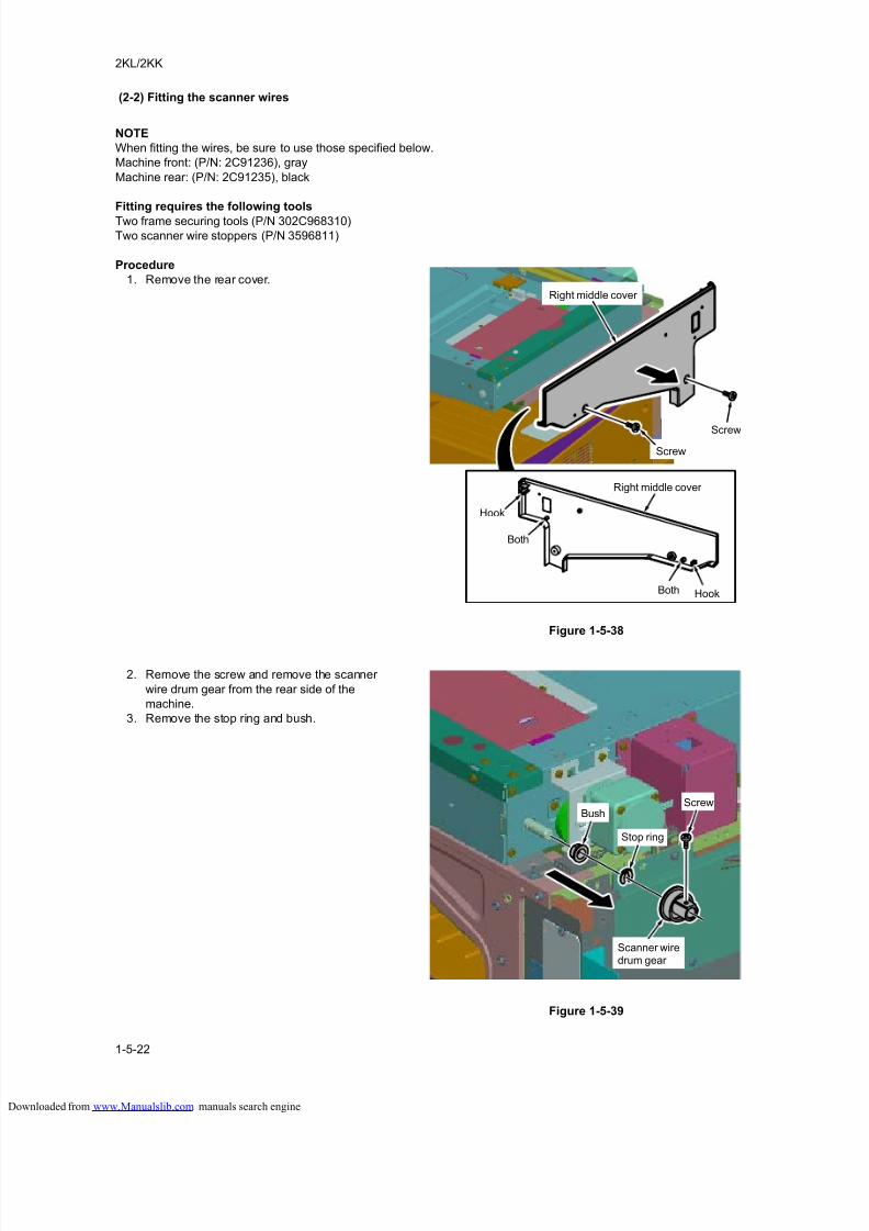
8/18/2019 taskalfa_220
http://slidepdf.com/reader/full/taskalfa220 164/300
2KL/2KK
1-5-22
(2-2) Fitting the scanner wires
NOTE
When fitting the wires, be sure to use those specified below.
Machine front: (P/N: 2C91236), gray
Machine rear: (P/N: 2C91235), black
Fitting requires the following tools
Two frame securing tools (P/N 302C968310)
Two scanner wire stoppers (P/N 3596811)
Procedure
1. Remove the rear cover.
Figure 1-5-38
2. Remove the screw and remove the scanner
wire drum gear from the rear side of the
machine.
3. Remove the stop ring and bush.
Figure 1-5-39
Right middle cover
Right middle cover
Screw
Screw
Hook
Hook
Both
Both
Bush
Stop ring
Screw
Scanner wiredrum gear
loaded from www.Manualslib.com manuals search engine
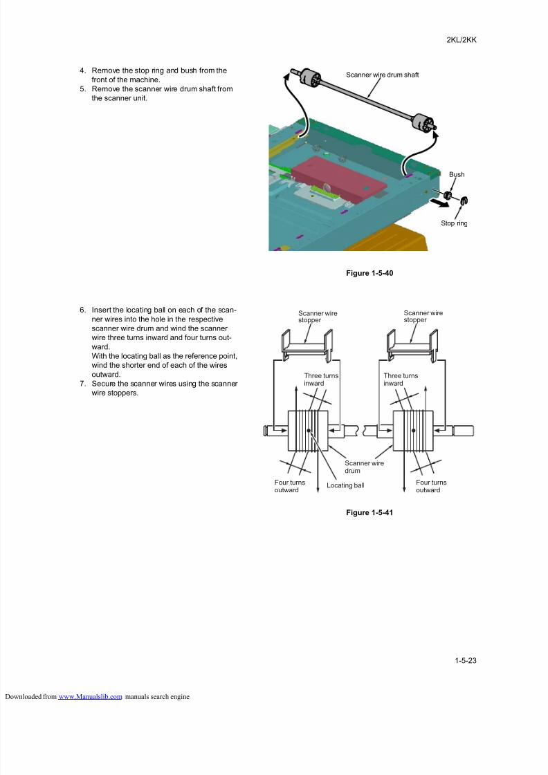
8/18/2019 taskalfa_220
http://slidepdf.com/reader/full/taskalfa220 165/300
2KL/2KK
1-5-23
4. Remove the stop ring and bush from the
front of the machine.
5. Remove the scanner wire drum shaft from
the scanner unit.
Figure 1-5-40
6. Insert the locating ball on each of the scan-
ner wires into the hole in the respective
scanner wire drum and wind the scanner
wire three turns inward and four turns out-
ward.
With the locating ball as the reference point,
wind the shorter end of each of the wires
outward.
7. Secure the scanner wires using the scanner
wire stoppers.
Figure 1-5-41
Scanner wire drum shaft
Bush
Stop ring
Three turnsinward
Three turnsinward
Four turnsoutward
Four turnsoutward
Locating ball
Scanner wiredrum
Scanner wirestopper
Scanner wirestopper
loaded from www.Manualslib.com manuals search engine
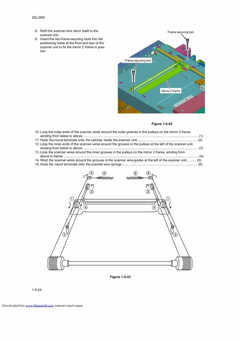
8/18/2019 taskalfa_220
http://slidepdf.com/reader/full/taskalfa220 166/300
2KL/2KK
1-5-24
8. Refit the scanner wire drum shaft to the
scanner unit.
9. Insert the two frame securing tools into the
positioning holes at the front and rear of the
scanner unit to fix the mirror 2 frame in posi-
tion.
Figure 1-5-42
10. Loop the outer ends of the scanner wires around the outer grooves in the pulleys on the mirror 2 frame,
winding from below to above. ..................... ................. ................. ................. ................. ................... .............. (1)
11. Hook the round terminals onto the catches inside the scanner unit. .................. ................. .................. .......... (2)
12. Loop the inner ends of the scanner wires around the grooves in the pulleys at the left of the scanner unit,
winding from below to above. ..................... ................. ................. ................. ................. ................... .............. (3)
13. Loop the scanner wires around the inner grooves in the pulleys on the mirror 2 frame, winding from
above to below.................... ................. ................. ................... ................. .................. ................. ................ .... (4)
14. Wind the scanner wires around the grooves in the scanner wire guides at the left of the scanner unit. ......... (5)
15. Hook the round terminals onto the scanner wire springs................. .................... .................... ...................... .. (6)
Figure 1-5-43
Frame securing tool
Mirror 2 frame
Frame securing tool
loaded from www.Manualslib.com manuals search engine
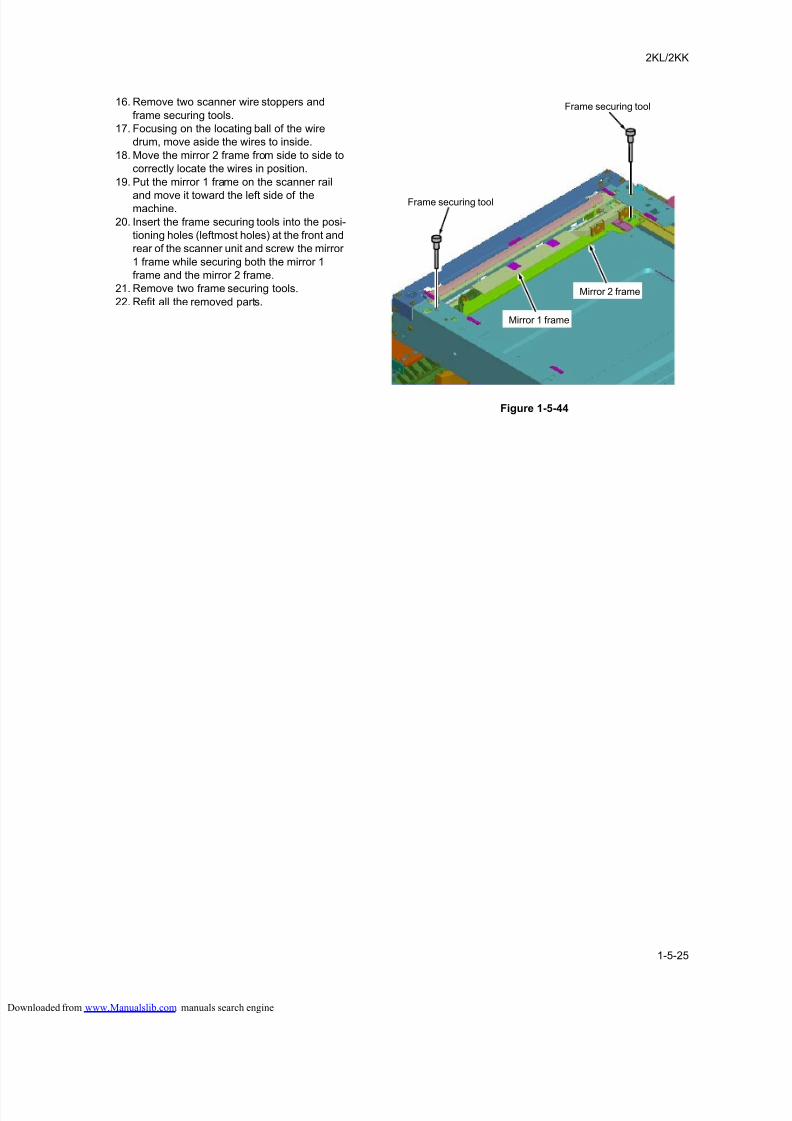
8/18/2019 taskalfa_220
http://slidepdf.com/reader/full/taskalfa220 167/300
2KL/2KK
1-5-25
16. Remove two scanner wire stoppers and
frame securing tools.
17. Focusing on the locating ball of the wire
drum, move aside the wires to inside.
18. Move the mirror 2 frame from side to side to
correctly locate the wires in position.
19. Put the mirror 1 frame on the scanner rail
and move it toward the left side of themachine.
20. Insert the frame securing tools into the posi-
tioning holes (leftmost holes) at the front and
rear of the scanner unit and screw the mirror
1 frame while securing both the mirror 1
frame and the mirror 2 frame.
21. Remove two frame securing tools.
22. Refit all the removed parts.
Figure 1-5-44
Frame securing tool
Frame securing tool
Mirror 2 frame
Mirror 1 frame
loaded from www.Manualslib.com manuals search engine
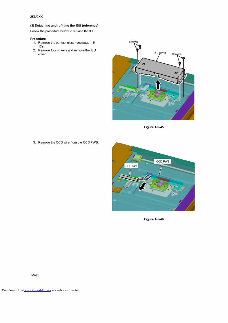
8/18/2019 taskalfa_220
http://slidepdf.com/reader/full/taskalfa220 168/300
2KL/2KK
1-5-26
(3) Detaching and refitting the ISU (reference)
Follow the procedure below to replace the ISU.
Procedure
1. Remove the contact glass (see page 1-5-
17).
2. Remove four screws and remove the ISU
cover.
Figure 1-5-45
3. Remove the CCD wire from the CCD PWB.
Figure 1-5-46
ISU cover
Screws
Screws
CCD wire
CCD PWB
loaded from www.Manualslib.com manuals search engine
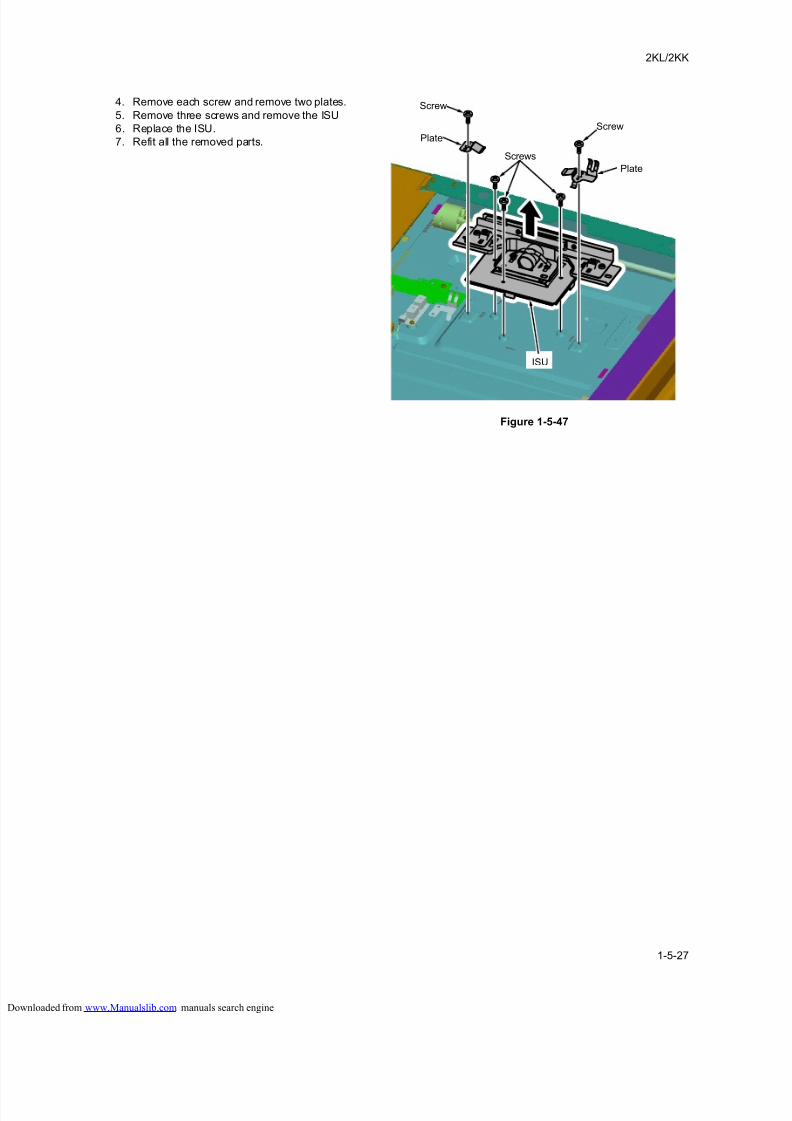
8/18/2019 taskalfa_220
http://slidepdf.com/reader/full/taskalfa220 169/300
2KL/2KK
1-5-27
4. Remove each screw and remove two plates.
5. Remove three screws and remove the ISU
6. Replace the ISU.
7. Refit all the removed parts.
Figure 1-5-47
Screws
Plate
Screw
Screw
Plate
ISU
loaded from www.Manualslib.com manuals search engine
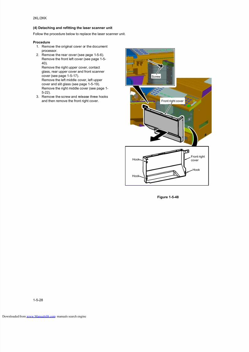
8/18/2019 taskalfa_220
http://slidepdf.com/reader/full/taskalfa220 170/300
2KL/2KK
1-5-28
(4) Detaching and refitting the laser scanner unit
Follow the procedure below to replace the laser scanner unit.
Procedure
1. Remove the original cover or the document
processor.
2. Remove the rear cover (see page 1-5-6).
Remove the front left cover (see page 1-5-
40).
Remove the right upper cover, contact
glass, rear upper cover and front scanner
cover (see page 1-5-17).
Remove the left middle cover, left upper
cover and slit glass (see page 1-5-19).
Remove the right middle cover (see page 1-
5-22).
3. Remove the screw and release three hooks
and then remove the front right cover.
Figure 1-5-48
Front right cover
Screw
Front rightcover Hook
Hook
Hook
loaded from www.Manualslib.com manuals search engine
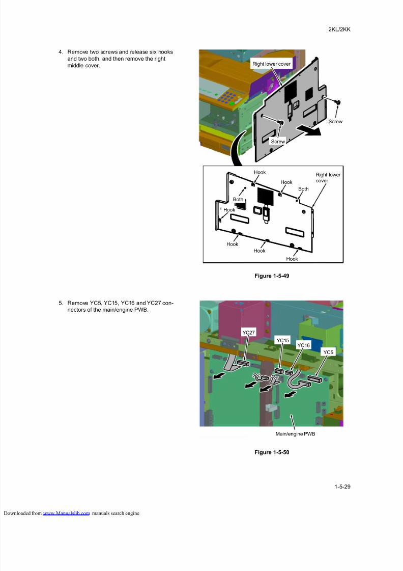
8/18/2019 taskalfa_220
http://slidepdf.com/reader/full/taskalfa220 171/300
2KL/2KK
1-5-29
4. Remove two screws and release six hooks
and two both, and then remove the right
middle cover.
Figure 1-5-49
5. Remove YC5, YC15, YC16 and YC27 con-
nectors of the main/engine PWB.
Figure 1-5-50
Right lower cover
Right lowercover
Screw
Screw
Hook
Hook
Hook
Hook
Hook
Hook
Both
Both
YC15YC16
YC27
YC5
Main/engine PWB
loaded from www.Manualslib.com manuals search engine
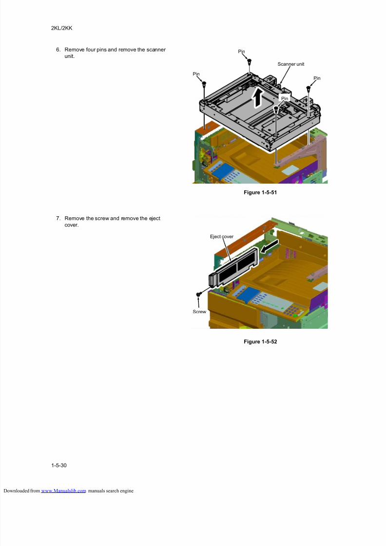
8/18/2019 taskalfa_220
http://slidepdf.com/reader/full/taskalfa220 172/300
2KL/2KK
1-5-30
6. Remove four pins and remove the scanner
unit.
Figure 1-5-51
7. Remove the screw and remove the eject
cover.
Figure 1-5-52
Pin
Pin
Pin
Scanner unit
Pin
Eject cover
Screw
loaded from www.Manualslib.com manuals search engine
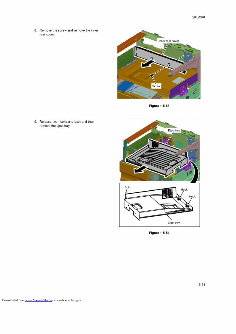
8/18/2019 taskalfa_220
http://slidepdf.com/reader/full/taskalfa220 173/300
2KL/2KK
1-5-31
8. Remove the screw and remove the inner
rear cover.
Figure 1-5-53
9. Release two hooks and both and then
remove the eject tray.
Figure 1-5-54
Inner rear cover
Screw
Eject tray
BothHook
Eject tray
Hook
loaded from www.Manualslib.com manuals search engine
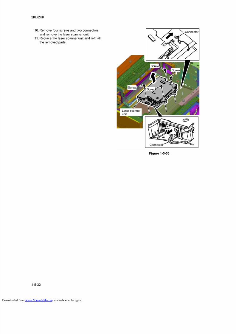
8/18/2019 taskalfa_220
http://slidepdf.com/reader/full/taskalfa220 174/300
2KL/2KK
1-5-32
10. Remove four screws and two connectors
and remove the laser scanner unit.
11. Replace the laser scanner unit and refit all
the removed parts.
Figure 1-5-55
Screw
Connector
Connector
Screw
Screw
Laser scanner unit
Screw
loaded from www.Manualslib.com manuals search engine
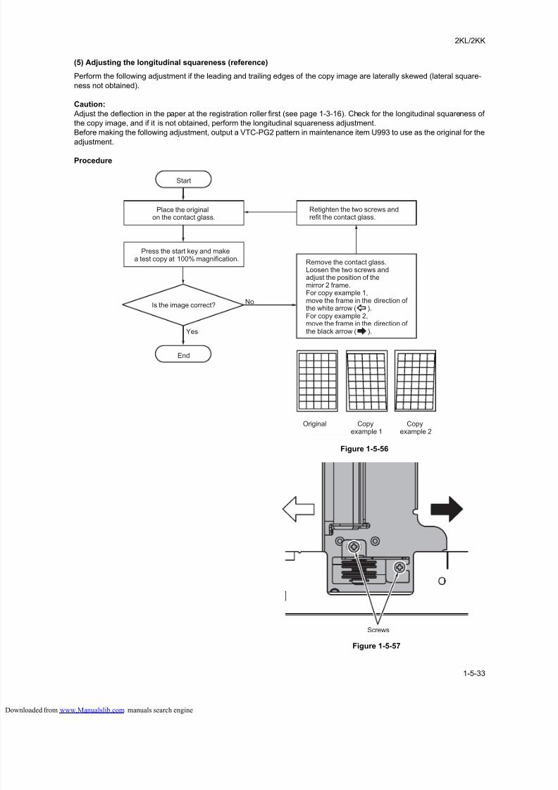
8/18/2019 taskalfa_220
http://slidepdf.com/reader/full/taskalfa220 175/300
2KL/2KK
1-5-33
(5) Adjusting the longitudinal squareness (reference)
Perform the following adjustment if the leading and trailing edges of the copy image are laterally skewed (lateral square-
ness not obtained).
Caution:
Adjust the deflection in the paper at the registration roller first (see page 1-3-16). Check for the longitudinal squareness of
the copy image, and if it is not obtained, perform the longitudinal squareness adjustment.
Before making the following adjustment, output a VTC-PG2 pattern in maintenance item U993 to use as the original for the
adjustment.
Procedure
Figure 1-5-56
Figure 1-5-57
Yes
No
Press the start key and makea test copy at 100% magnification.
Start
Remove the contact glass.Loosen the two screws and
adjust the position of themirror 2 frame.For copy example 1,move the frame in the direction ofthe white arrow ( ).For copy example 2,move the frame in the direction ofthe black arrow ( ).
End
Is the image correct?
Place the originalon the contact glass.
Retighten the two screws andrefit the contact glass.
Original Copyexample 1
Copyexample 2
Screws
loaded from www.Manualslib.com manuals search engine
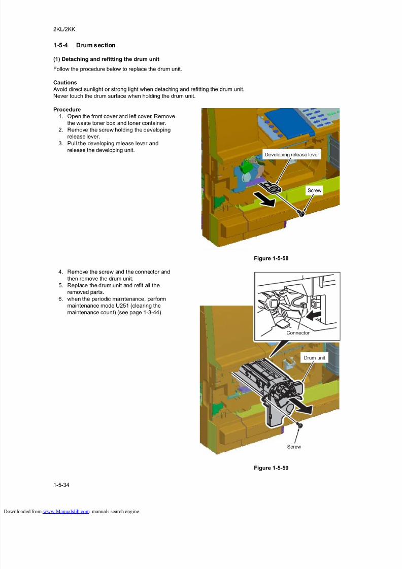
8/18/2019 taskalfa_220
http://slidepdf.com/reader/full/taskalfa220 176/300
2KL/2KK
1-5-34
1-5-4 Drum section
(1) Detaching and refitting the drum unit
Follow the procedure below to replace the drum unit.
Cautions
Avoid direct sunlight or strong light when detaching and refitting the drum unit.
Never touch the drum surface when holding the drum unit.
Procedure
1. Open the front cover and left cover. Remove
the waste toner box and toner container.
2. Remove the screw holding the developing
release lever.
3. Pull the developing release lever and
release the developing unit.
Figure 1-5-58
4. Remove the screw and the connector and
then remove the drum unit.
5. Replace the drum unit and refit all the
removed parts.
6. when the periodic maintenance, performmaintenance mode U251 (clearing the
maintenance count) (see page 1-3-44).
Figure 1-5-59
Developing release lever
Screw
Drum unit
Connector
Screw
loaded from www.Manualslib.com manuals search engine
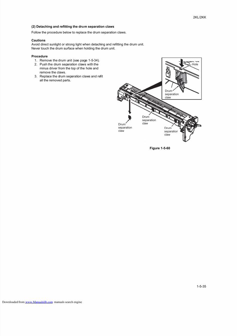
8/18/2019 taskalfa_220
http://slidepdf.com/reader/full/taskalfa220 177/300
2KL/2KK
1-5-35
(2) Detaching and refitting the drum separation claws
Follow the procedure below to replace the drum separation claws.
Cautions
Avoid direct sunlight or strong light when detaching and refitting the drum unit.
Never touch the drum surface when holding the drum unit.
Procedure
1. Remove the drum unit (see page 1-5-34).
2. Push the drum separation claws with the
minus driver from the top of the hole and
remove the claws.
3. Replace the drum separation claws and refit
all the removed parts.
Figure 1-5-60
Hole
Drumseparationclaw
Drumseparationclaw
Drumseparationclaw
Drumseparationclaw
loaded from www.Manualslib.com manuals search engine
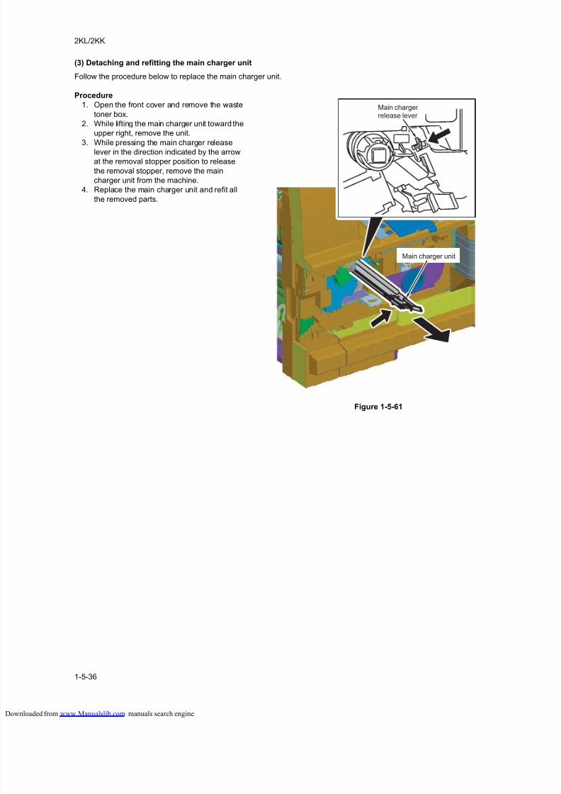
8/18/2019 taskalfa_220
http://slidepdf.com/reader/full/taskalfa220 178/300
2KL/2KK
1-5-36
(3) Detaching and refitting the main charger unit
Follow the procedure below to replace the main charger unit.
Procedure
1. Open the front cover and remove the waste
toner box.
2. While lifting the main charger unit toward the
upper right, remove the unit.
3. While pressing the main charger release
lever in the direction indicated by the arrow
at the removal stopper position to release
the removal stopper, remove the main
charger unit from the machine.
4. Replace the main charger unit and refit all
the removed parts.
Figure 1-5-61
Main charger unit
Main chargerrelease lever
loaded from www.Manualslib.com manuals search engine
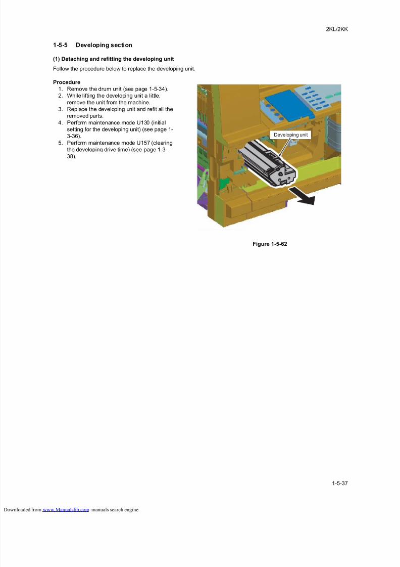
8/18/2019 taskalfa_220
http://slidepdf.com/reader/full/taskalfa220 179/300
2KL/2KK
1-5-37
1-5-5 Developing section
(1) Detaching and refitting the developing unit
Follow the procedure below to replace the developing unit.
Procedure
1. Remove the drum unit (see page 1-5-34).
2. While lifting the developing unit a little,
remove the unit from the machine.
3. Replace the developing unit and refit all the
removed parts.
4. Perform maintenance mode U130 (initial
setting for the developing unit) (see page 1-
3-36).
5. Perform maintenance mode U157 (clearing
the developing drive time) (see page 1-3-
38).
Figure 1-5-62
Developing unit
loaded from www.Manualslib.com manuals search engine
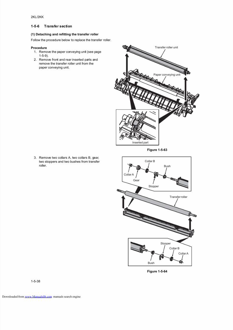
8/18/2019 taskalfa_220
http://slidepdf.com/reader/full/taskalfa220 180/300
2KL/2KK
1-5-38
1-5-6 Transfer section
(1) Detaching and refitting the transfer roller
Follow the procedure below to replace the transfer roller.
Procedure
1. Remove the paper conveying unit (see page
1-5-9).
2. Remove front and rear inserted parts and
remove the transfer roller unit from the
paper conveying unit.
Figure 1-5-63
3. Remove two collars A, two collars B, gear,
two stoppers and two bushes from transfer
roller.
Figure 1-5-64
Transfer roller unit
Paper conveying unit
Inserted part
Bush
Collar A
Gear
Stopper
Bush
Stopper
Collar B
Collar A
Collar B
Transfer roller
loaded from www.Manualslib.com manuals search engine
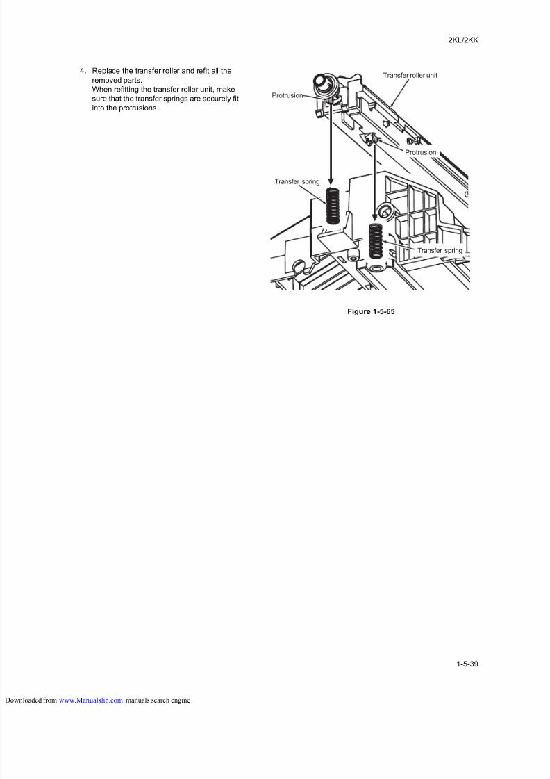
8/18/2019 taskalfa_220
http://slidepdf.com/reader/full/taskalfa220 181/300
2KL/2KK
1-5-39
4. Replace the transfer roller and refit all the
removed parts.
When refitting the transfer roller unit, make
sure that the transfer springs are securely fit
into the protrusions.
Figure 1-5-65
Transfer roller unit
Transfer spring
Protrusion
Protrusion
Transfer spring
loaded from www.Manualslib.com manuals search engine
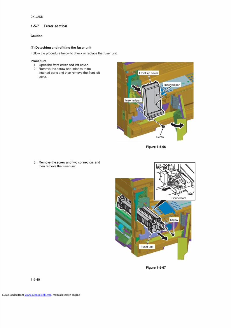
8/18/2019 taskalfa_220
http://slidepdf.com/reader/full/taskalfa220 182/300
2KL/2KK
1-5-40
1-5-7 Fuser section
Caution
(1) Detaching and refitting the fuser unit
Follow the procedure below to check or replace the fuser unit.
Procedure
1. Open the front cover and left cover.
2. Remove the screw and release three
inserted parts and then remove the front left
cover.
Figure 1-5-66
3. Remove the screw and two connectors and
then remove the fuser unit.
Figure 1-5-67
Front left cover
Inserted part
Screw
Inserted part
Fuser unit
Screw
Connectors
loaded from www.Manualslib.com manuals search engine
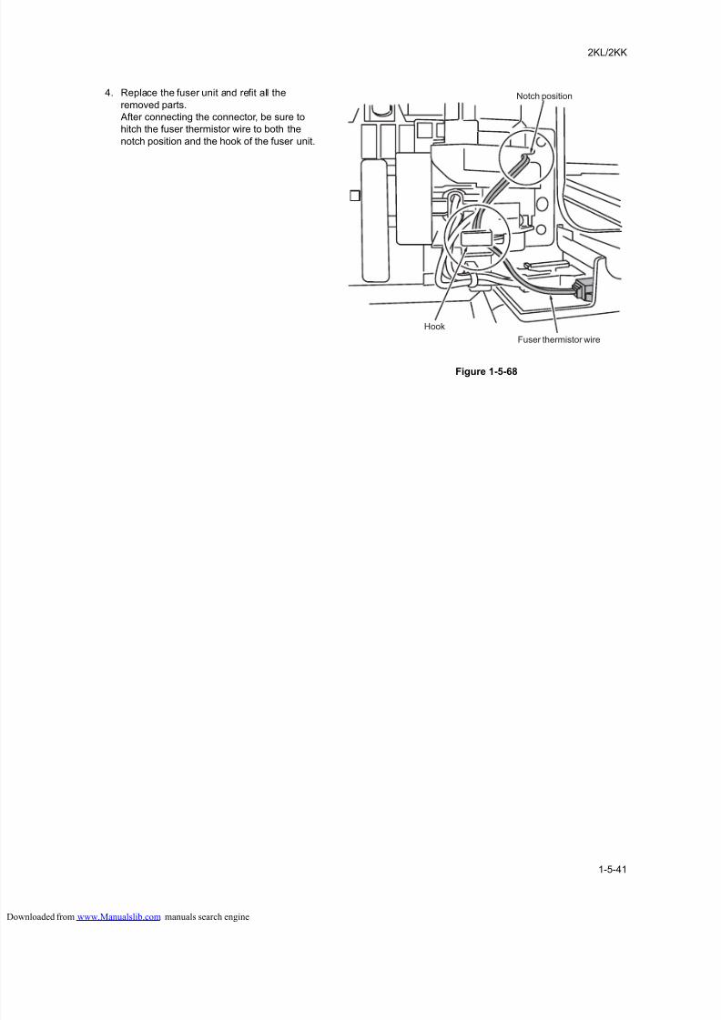
8/18/2019 taskalfa_220
http://slidepdf.com/reader/full/taskalfa220 183/300
2KL/2KK
1-5-41
4. Replace the fuser unit and refit all the
removed parts.
After connecting the connector, be sure to
hitch the fuser thermistor wire to both the
notch position and the hook of the fuser unit.
Figure 1-5-68
Hook
Notch position
Fuser thermistor wire
loaded from www.Manualslib.com manuals search engine
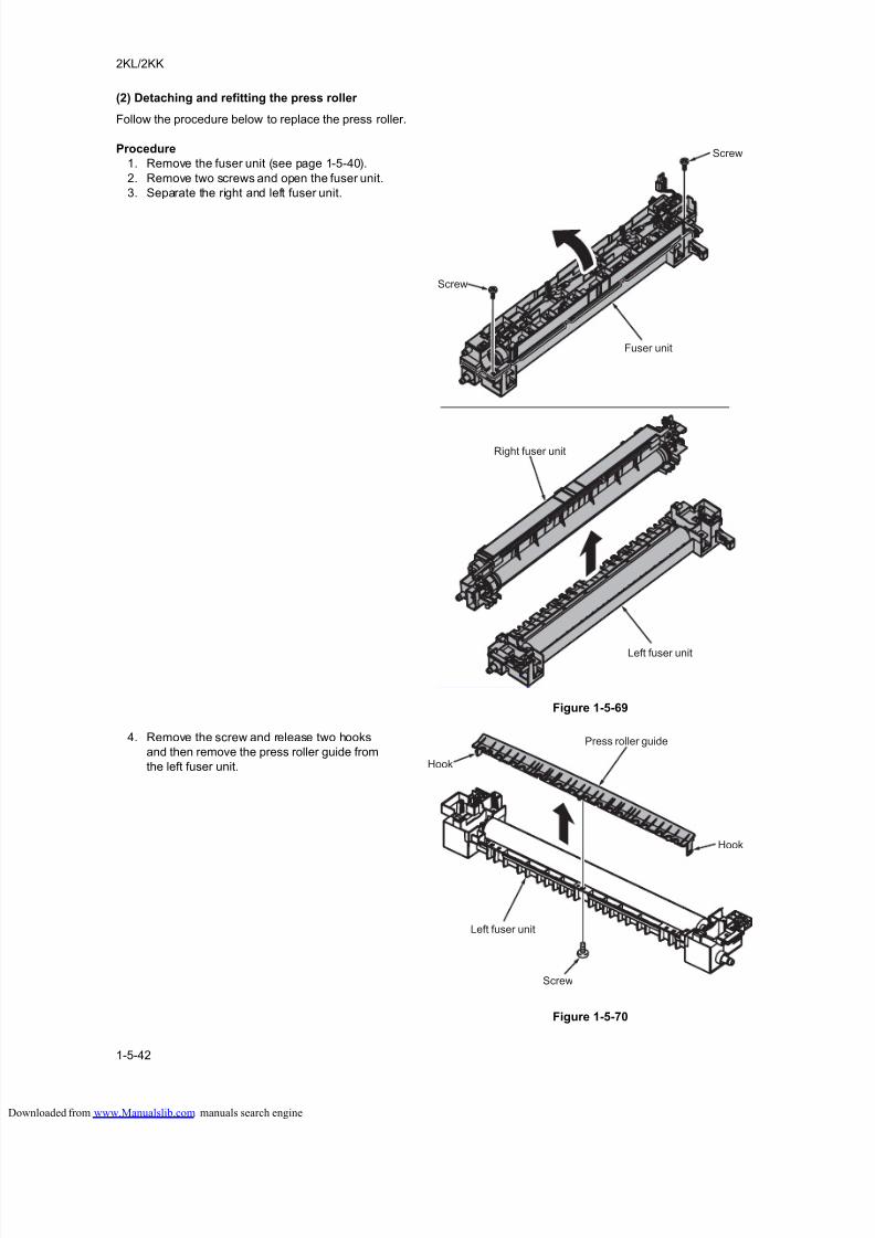
8/18/2019 taskalfa_220
http://slidepdf.com/reader/full/taskalfa220 184/300
2KL/2KK
1-5-42
(2) Detaching and refitting the press roller
Follow the procedure below to replace the press roller.
Procedure
1. Remove the fuser unit (see page 1-5-40).
2. Remove two screws and open the fuser unit.
3. Separate the right and left fuser unit.
Figure 1-5-69
4. Remove the screw and release two hooks
and then remove the press roller guide from
the left fuser unit.
Figure 1-5-70
Right fuser unit
Left fuser unit
Fuser unit
Screw
Screw
Press roller guide
Hook
Hook
Screw
Left fuser unit
loaded from www.Manualslib.com manuals search engine
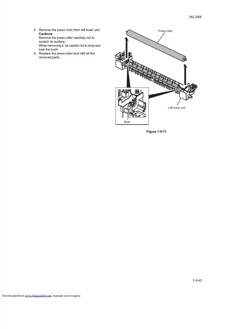
8/18/2019 taskalfa_220
http://slidepdf.com/reader/full/taskalfa220 185/300
2KL/2KK
1-5-43
5. Remove the press roller from left fuser unit.
Cautions
Remove the press roller carefully not to
scratch its surface.
When removing it, be careful not to drop and
lose the bush.
6. Replace the press roller and refit all the
removed parts.
Figure 1-5-71
Press roller
Left fuser unit
Bush
loaded from www.Manualslib.com manuals search engine
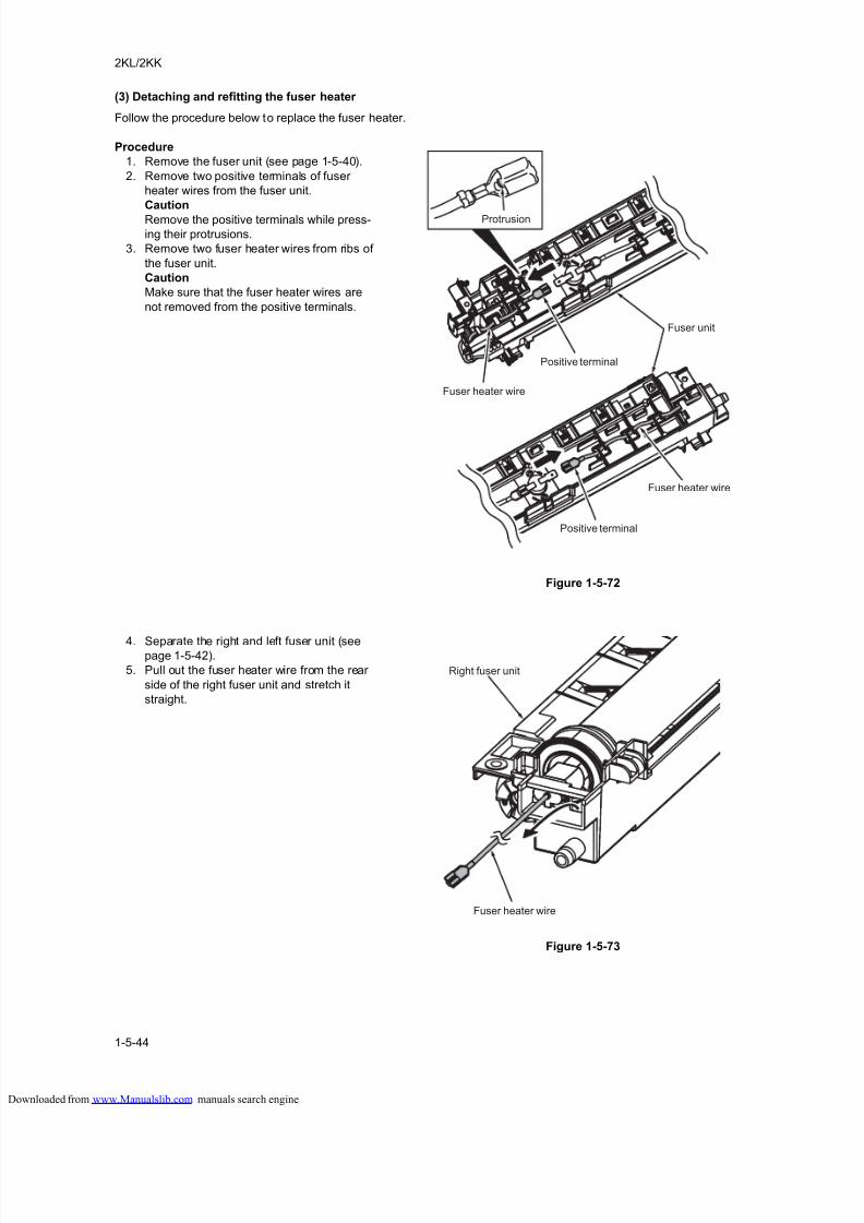
8/18/2019 taskalfa_220
http://slidepdf.com/reader/full/taskalfa220 186/300
2KL/2KK
1-5-44
(3) Detaching and refitting the fuser heater
Follow the procedure below to replace the fuser heater.
Procedure
1. Remove the fuser unit (see page 1-5-40).
2. Remove two positive terminals of fuser
heater wires from the fuser unit.
Caution
Remove the positive terminals while press-
ing their protrusions.
3. Remove two fuser heater wires from ribs of
the fuser unit.
Caution
Make sure that the fuser heater wires are
not removed from the positive terminals.
Figure 1-5-72
4. Separate the right and left fuser unit (seepage 1-5-42).
5. Pull out the fuser heater wire from the rear
side of the right fuser unit and stretch it
straight.
Figure 1-5-73
Positive terminal
Protrusion
Fuser heater wire
Fuser unit
Positive terminal
Fuser heater wire
Fuser heater wire
Right fuser unit
loaded from www.Manualslib.com manuals search engine
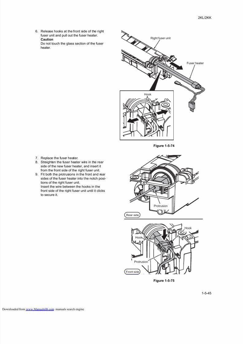
8/18/2019 taskalfa_220
http://slidepdf.com/reader/full/taskalfa220 187/300
2KL/2KK
1-5-45
6. Release hooks at the front side of the right
fuser unit and pull out the fuser heater.
Caution
Do not touch the glass section of the fuser
heater.
Figure 1-5-74
7. Replace the fuser heater.
8. Straighten the fuser heater wire in the rear
side of the new fuser heater, and insert it
from the front side of the right fuser unit.
9. Fit both the protrusions in the front and rear
sides of the fuser heater into the notch posi-
tions of the right fuser unit.
Insert the wire between the hooks in the
front side of the right fuser unit until it clicks
to secure it.
Figure 1-5-75
Fuser heater
Hook
Right fuser unit
Hook
Protrusion
Rear side
Protrusion
Hook
Front side
loaded from www.Manualslib.com manuals search engine
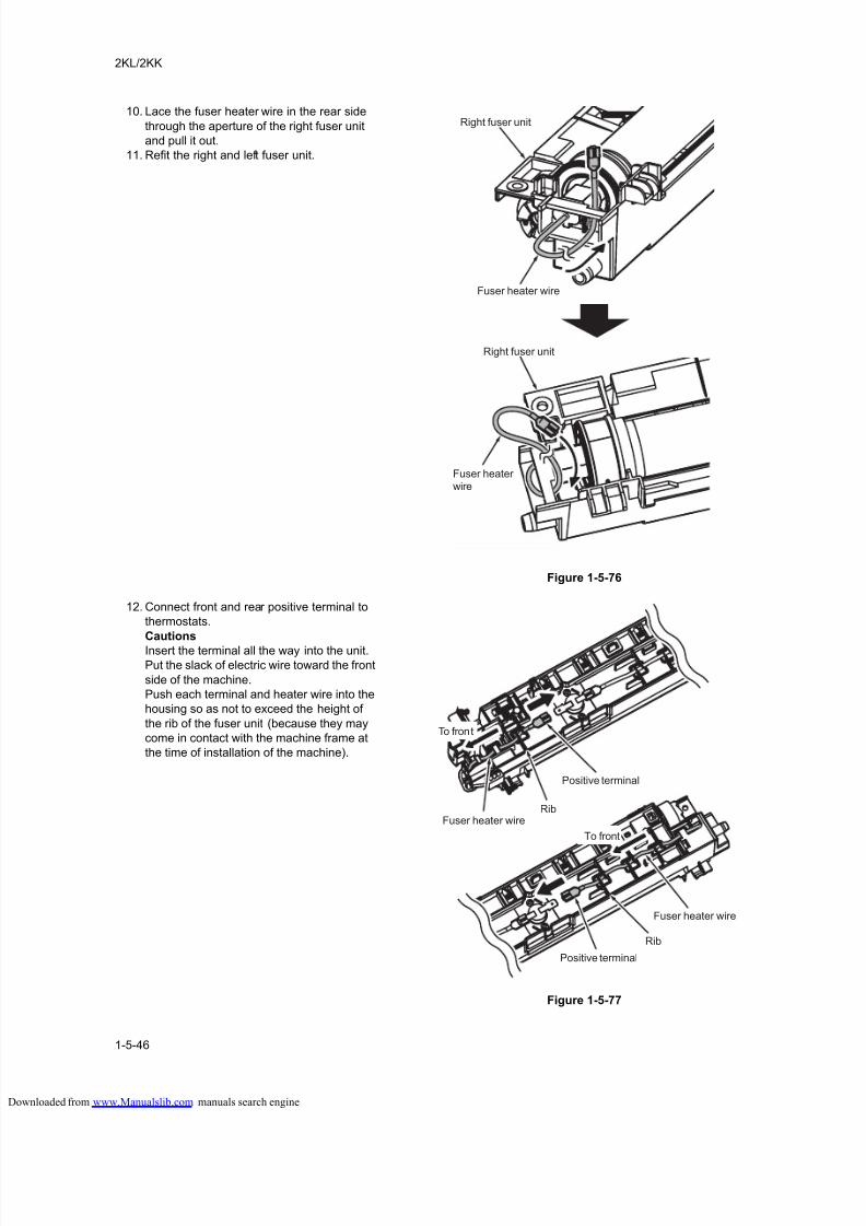
8/18/2019 taskalfa_220
http://slidepdf.com/reader/full/taskalfa220 188/300
2KL/2KK
1-5-46
10. Lace the fuser heater wire in the rear side
through the aperture of the right fuser unit
and pull it out.
11. Refit the right and left fuser unit.
Figure 1-5-76
12. Connect front and rear positive terminal to
thermostats.
Cautions
Insert the terminal all the way into the unit.
Put the slack of electric wire toward the front
side of the machine.
Push each terminal and heater wire into the
housing so as not to exceed the height of
the rib of the fuser unit (because they may
come in contact with the machine frame at
the time of installation of the machine).
Figure 1-5-77
Fuser heater wire
Fuser heaterwire
Right fuser unit
Right fuser unit
Positive terminal
Fuser heater wireRib
Rib
To front
To front
Positive terminal
Fuser heater wire
loaded from www.Manualslib.com manuals search engine
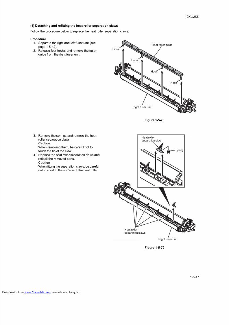
8/18/2019 taskalfa_220
http://slidepdf.com/reader/full/taskalfa220 189/300
2KL/2KK
1-5-47
(4) Detaching and refitting the heat roller separation claws
Follow the procedure below to replace the heat roller separation claws.
Procedure
1. Separate the right and left fuser unit (see
page 1-5-42).
2. Release four hooks and remove the fuser
guide from the right fuser unit.
Figure 1-5-78
3. Remove the springs and remove the heat
roller separation claws.
Caution
When removing them, be careful not to
touch the tip of the claw.
4. Replace the heat roller separation claws and
refit all the removed parts.
Caution
When fitting the separation claws, be careful
not to scratch the surface of the heat roller.
Figure 1-5-79
Heat roller guide
Hook
Hook
Hook
Hook
Right fuser unit
Heat rollerseparation claws
Right fuser unit
Heat rollerseparation claw
Spring
loaded from www.Manualslib.com manuals search engine
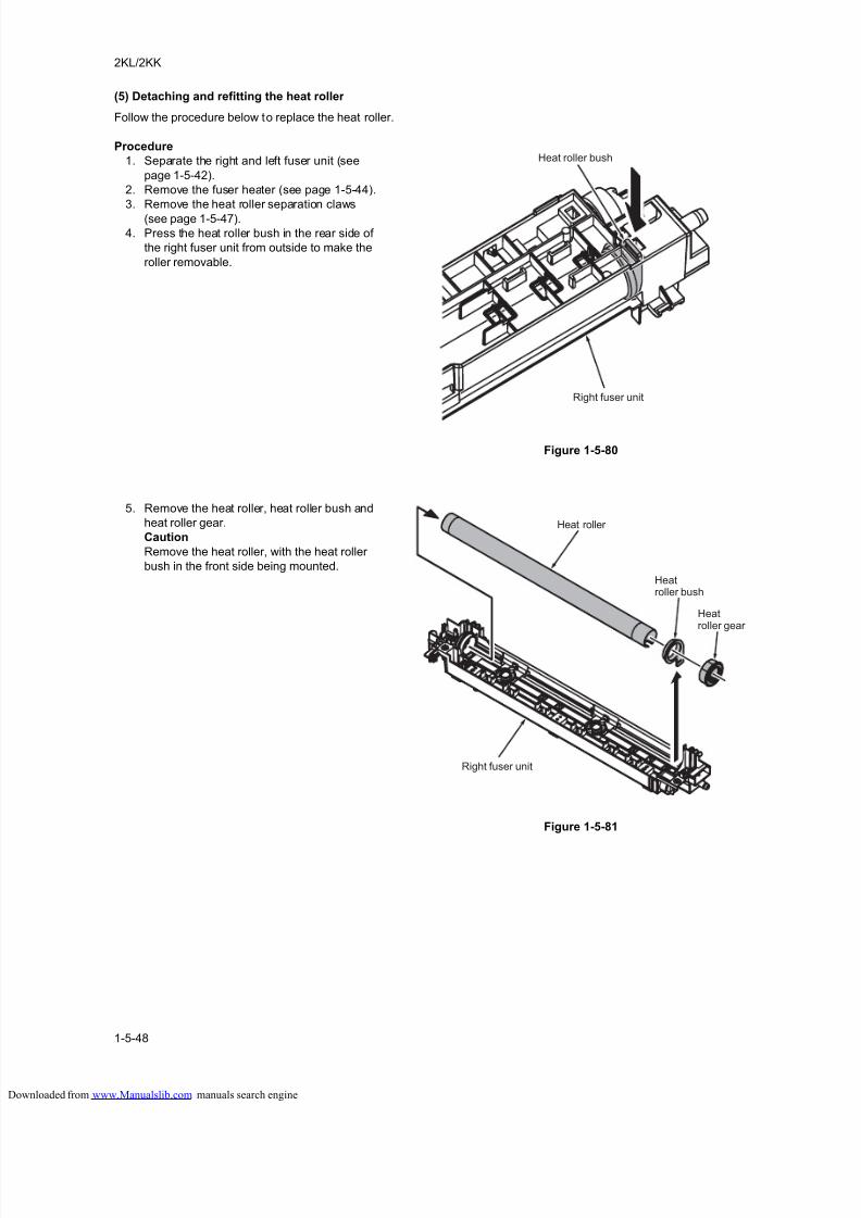
8/18/2019 taskalfa_220
http://slidepdf.com/reader/full/taskalfa220 190/300
2KL/2KK
1-5-48
(5) Detaching and refitting the heat roller
Follow the procedure below to replace the heat roller.
Procedure
1. Separate the right and left fuser unit (see
page 1-5-42).
2. Remove the fuser heater (see page 1-5-44).
3. Remove the heat roller separation claws
(see page 1-5-47).
4. Press the heat roller bush in the rear side of
the right fuser unit from outside to make the
roller removable.
Figure 1-5-80
5. Remove the heat roller, heat roller bush and
heat roller gear.
Caution
Remove the heat roller, with the heat roller
bush in the front side being mounted.
Figure 1-5-81
Heat roller bush
Right fuser unit
Heat roller
Right fuser unit
Heatroller bush
Heatroller gear
loaded from www.Manualslib.com manuals search engine
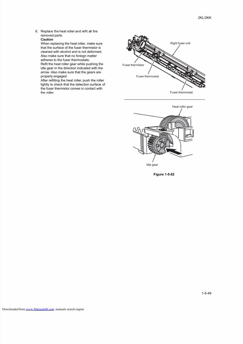
8/18/2019 taskalfa_220
http://slidepdf.com/reader/full/taskalfa220 191/300
2KL/2KK
1-5-49
6. Replace the heat roller and refit all the
removed parts.
Caution
When replacing the heat roller, make sure
that the surface of the fuser thermistor is
cleaned with alcohol and is not deformed.
Also make sure that no foreign matter
adheres to the fuser thermostats.Refit the heat roller gear while pushing the
idle gear in the direction indicated with the
arrow. Also make sure that the gears are
properly engaged.
After refitting the heat roller, push the roller
lightly to check that the detection surface of
the fuser thermistor comes in contact with
the roller.
Figure 1-5-82
Fuser thermistor
Fuser thermostat
Fuser thermostat
Right fuser unit
Idle gear
Heat roller gear
loaded from www.Manualslib.com manuals search engine
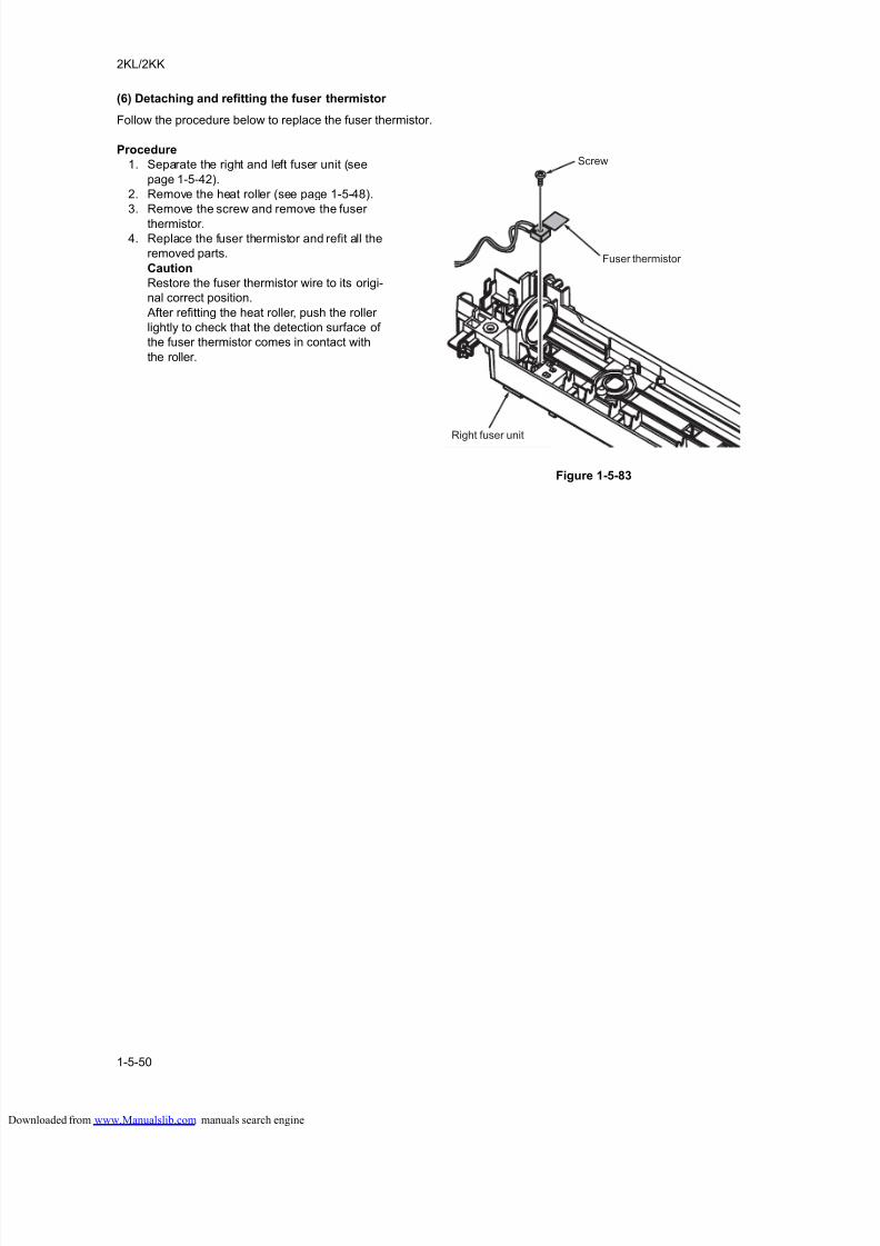
8/18/2019 taskalfa_220
http://slidepdf.com/reader/full/taskalfa220 192/300
2KL/2KK
1-5-50
(6) Detaching and refitting the fuser thermistor
Follow the procedure below to replace the fuser thermistor.
Procedure
1. Separate the right and left fuser unit (see
page 1-5-42).
2. Remove the heat roller (see page 1-5-48).
3. Remove the screw and remove the fuser
thermistor.
4. Replace the fuser thermistor and refit all the
removed parts.
Caution
Restore the fuser thermistor wire to its origi-
nal correct position.
After refitting the heat roller, push the roller
lightly to check that the detection surface of
the fuser thermistor comes in contact with
the roller.
Figure 1-5-83
Fuser thermistor
Right fuser unit
Screw
loaded from www.Manualslib.com manuals search engine
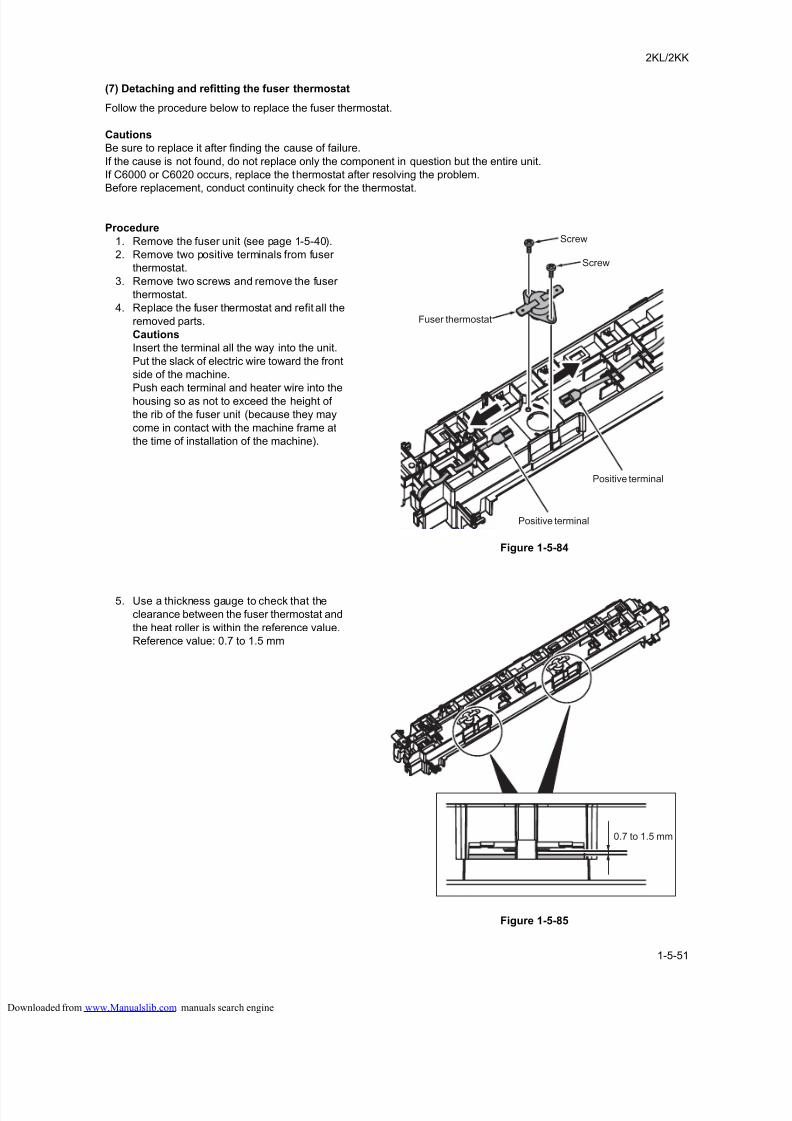
8/18/2019 taskalfa_220
http://slidepdf.com/reader/full/taskalfa220 193/300
2KL/2KK
1-5-51
(7) Detaching and refitting the fuser thermostat
Follow the procedure below to replace the fuser thermostat.
Cautions
Be sure to replace it after finding the cause of failure.
If the cause is not found, do not replace only the component in question but the entire unit.
If C6000 or C6020 occurs, replace the thermostat after resolving the problem.
Before replacement, conduct continuity check for the thermostat.
Procedure
1. Remove the fuser unit (see page 1-5-40).
2. Remove two positive terminals from fuser
thermostat.
3. Remove two screws and remove the fuser
thermostat.
4. Replace the fuser thermostat and refit all the
removed parts.
Cautions
Insert the terminal all the way into the unit.
Put the slack of electric wire toward the front
side of the machine.
Push each terminal and heater wire into thehousing so as not to exceed the height of
the rib of the fuser unit (because they may
come in contact with the machine frame at
the time of installation of the machine).
Figure 1-5-84
5. Use a thickness gauge to check that the
clearance between the fuser thermostat and
the heat roller is within the reference value.
Reference value: 0.7 to 1.5 mm
Figure 1-5-85
Fuser thermostat
Screw
Screw
Positive terminal
Positive terminal
0.7 to 1.5 mm
loaded from www.Manualslib.com manuals search engine
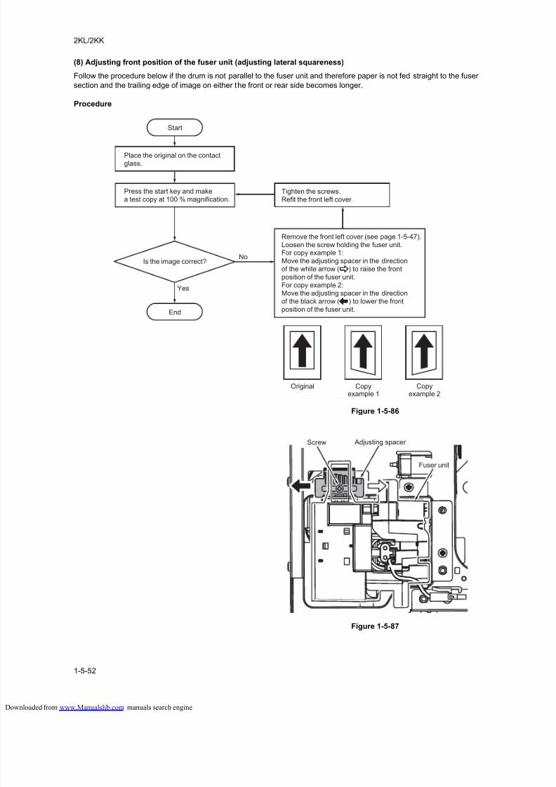
8/18/2019 taskalfa_220
http://slidepdf.com/reader/full/taskalfa220 194/300
2KL/2KK
1-5-52
(8) Adjusting front position of the fuser unit (adjusting lateral squareness)
Follow the procedure below if the drum is not parallel to the fuser unit and therefore paper is not fed straight to the fuser
section and the trailing edge of image on either the front or rear side becomes longer.
Procedure
Figure 1-5-86
Figure 1-5-87
Tighten the screws.Refit the front left cover.
Remove the front left cover (see page 1-5-47).Loosen the screw holding the fuser unit.For copy example 1:Move the adjusting spacer in the directionof the white arrow ( ) to raise the front
position of the fuser unit.For copy example 2:Move the adjusting spacer in the directionof the black arrow ( ) to lower the frontposition of the fuser unit.
Yes
No
Press the start key and makea test copy at 100 % magnification.
Start
End
Is the image correct?
Place the original on the contactglass.
Original Copyexample 1
Copyexample 2
Screw Adjusting spacer
Fuser unit
loaded from www.Manualslib.com manuals search engine
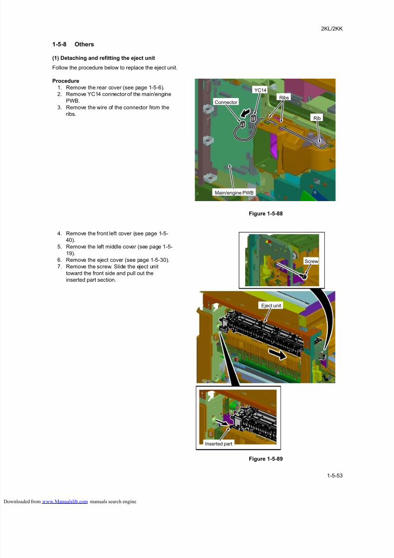
8/18/2019 taskalfa_220
http://slidepdf.com/reader/full/taskalfa220 195/300
2KL/2KK
1-5-53
1-5-8 Others
(1) Detaching and refitting the eject unit
Follow the procedure below to replace the eject unit.
Procedure
1. Remove the rear cover (see page 1-5-6).
2. Remove YC14 connector of the main/engine
PWB.
3. Remove the wire of the connector from the
ribs.
Figure 1-5-88
4. Remove the front left cover (see page 1-5-
40).
5. Remove the left middle cover (see page 1-5-
19).
6. Remove the eject cover (see page 1-5-30).
7. Remove the screw. Slide the eject unit
toward the front side and pull out the
inserted part section.
Figure 1-5-89
Main/engine PWB
YC14
Ribs
Rib
Connector
Screw
Eject unit
Inserted part
loaded from www.Manualslib.com manuals search engine
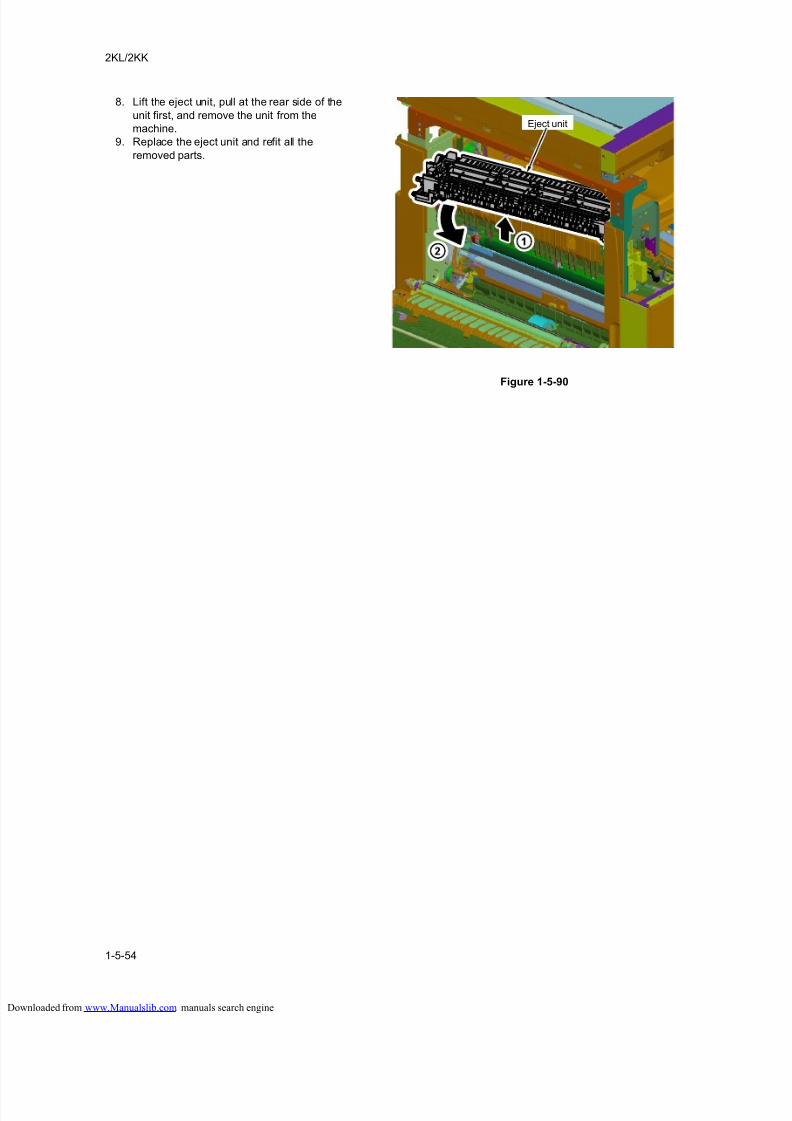
8/18/2019 taskalfa_220
http://slidepdf.com/reader/full/taskalfa220 196/300
2KL/2KK
1-5-54
8. Lift the eject unit, pull at the rear side of the
unit first, and remove the unit from the
machine.
9. Replace the eject unit and refit all the
removed parts.
Figure 1-5-90
Eject unit
loaded from www.Manualslib.com manuals search engine
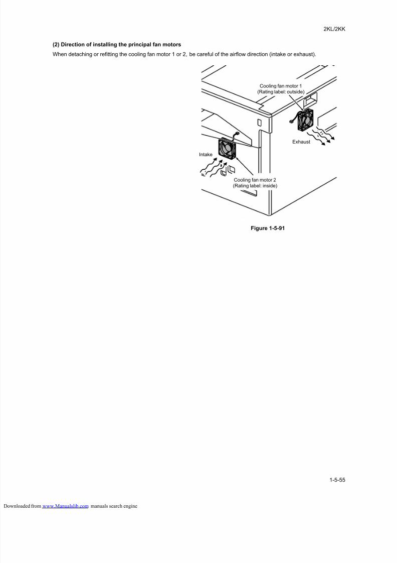
8/18/2019 taskalfa_220
http://slidepdf.com/reader/full/taskalfa220 197/300
2KL/2KK
1-5-55
(2) Direction of installing the principal fan motors
When detaching or refitting the cooling fan motor 1 or 2, be careful of the airflow direction (intake or exhaust).
Figure 1-5-91
Cooling fan motor 1(Rating label: outside)
Cooling fan motor 2(Rating label: inside)
Intake
Exhaust
loaded from www.Manualslib.com manuals search engine

8/18/2019 taskalfa_220
http://slidepdf.com/reader/full/taskalfa220 198/300
2KL/2KK
1-5-56
This page is intentionally left blank.
loaded from www.Manualslib.com manuals search engine
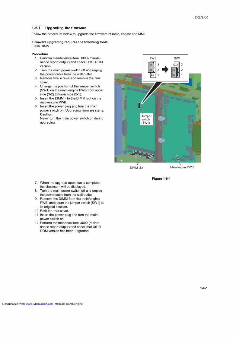
8/18/2019 taskalfa_220
http://slidepdf.com/reader/full/taskalfa220 199/300
2KL/2KK
1-6-1
1-6 RequirementsonPWB Replacement
1-6-1 Upgrading the firmware
Follow the procedure below to upgrade the firmware of main, engine and MMI.
Firmware upgrading requires the following tools:
Flash DIMM
Procedure
1. Perform maintenance item U000 (mainte-nance report output) and check U019 ROM
version.
2. Turn the main power switch off and unplug
the power cable from the wall outlet.
3. Remove five screws and remove the rear
cover.
4. Change the position of the jumper switch
(SW1) on the main/engine PWB from upper
side (3-2) to lower side (2-1).
5. Insert the DIMM into the DIMM slot on the
main/engine PWB.
6. Insert the power plug and turn the main
power switch on. Upgrading firmware starts.
Caution:
Never turn the main power switch off duringupgrading.
Figure 1-6-17. When the upgrade operation is complete,
the checksum will be displayed.
8. Turn the main power switch off and unplug
the power cable from the wall outlet.
9. Remove the DIMM from the main/engine
PWB, and return the jumper switch (SW1) to
its original position.
10. Refit the rear cover.
11. Insert the power plug and turn the main
power switch on.
12. Perform maintenance item U000 (mainte-
nance report output) and check that U019
ROM version has been upgraded.
3
2
1
3
2
1
SW1 SW1
Main/engine PWBDIMM slot
Jumper switch(SW1)
loaded from www.Manualslib.com manuals search engine
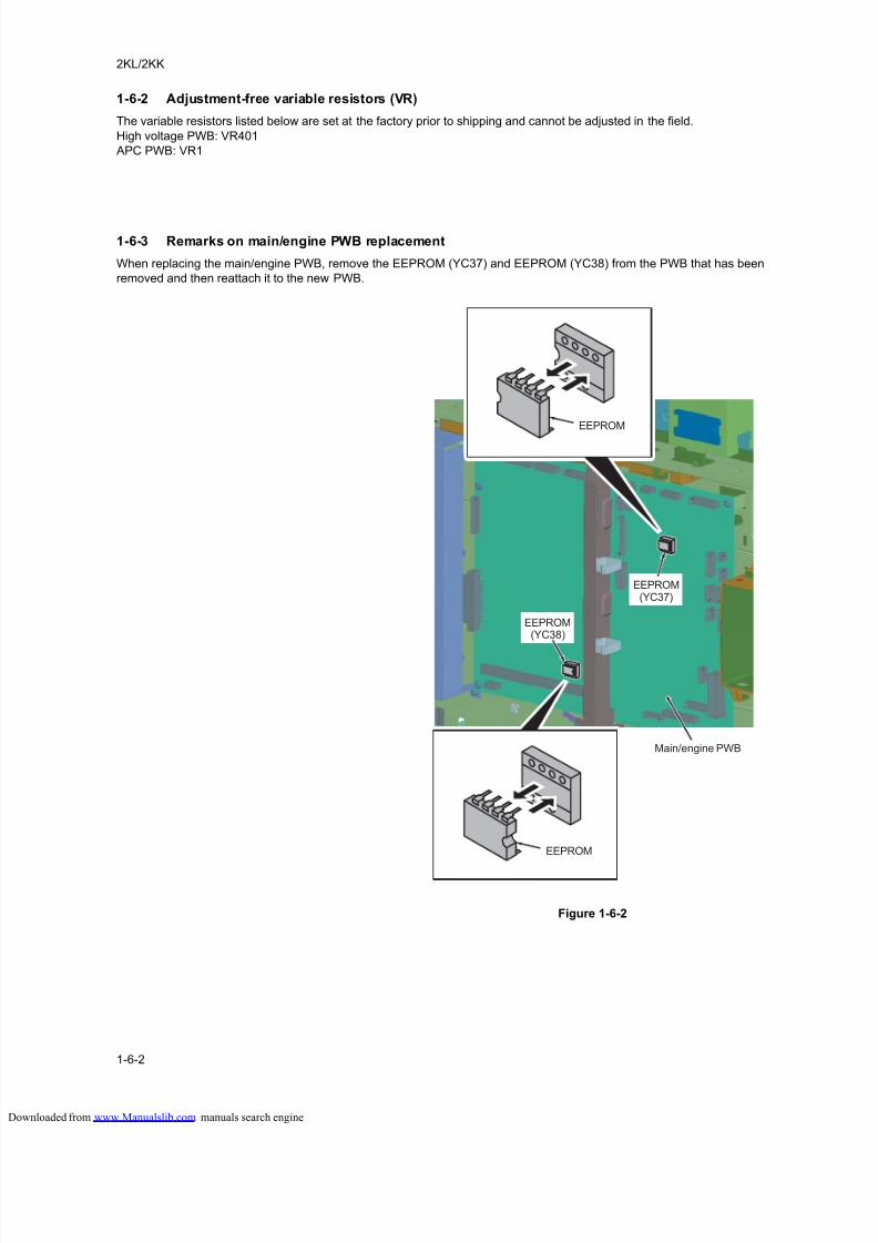
8/18/2019 taskalfa_220
http://slidepdf.com/reader/full/taskalfa220 200/300
2KL/2KK
1-6-2
1-6-2 Adjustment-free variable resistors (VR)
The variable resistors listed below are set at the factory prior to shipping and cannot be adjusted in the field.
High voltage PWB: VR401
APC PWB: VR1
1-6-3 Remarks on main/engine PWB replacement
When replacing the main/engine PWB, remove the EEPROM (YC37) and EEPROM (YC38) from the PWB that has been
removed and then reattach it to the new PWB.
Figure 1-6-2
Main/engine PWB
EEPROM
EEPROM(YC37)
EEPROM(YC38)
EEPROM
loaded from www.Manualslib.com manuals search engine
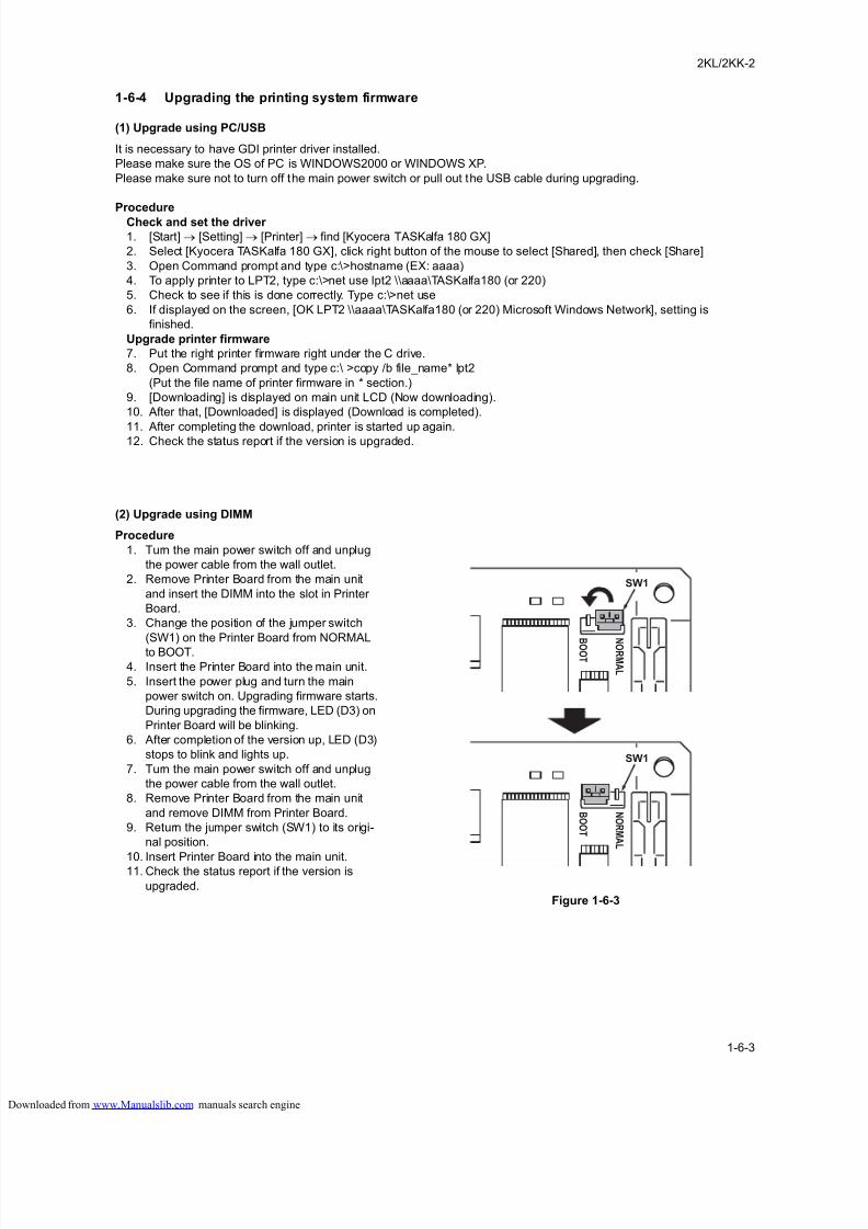
8/18/2019 taskalfa_220
http://slidepdf.com/reader/full/taskalfa220 201/300
2KL/2KK-2
1-6-3
1-6-4 Upgrading the printing system firmware
(1) Upgrade using PC/USB
It is necessary to have GDI printer driver installed.
Please make sure the OS of PC is WINDOWS2000 or WINDOWS XP.
Please make sure not to turn off the main power switch or pull out the USB cable during upgrading.
Procedure
Check and set the driver
1. [Start] → [Setting] → [Printer] → find [Kyocera TASKalfa 180 GX]
2. Select [Kyocera TASKalfa 180 GX], click right button of the mouse to select [Shared], then check [Share]
3. Open Command prompt and type c:\>hostname (EX: aaaa)
4. To apply printer to LPT2, type c:\>net use lpt2 \\aaaa\TASKalfa180 (or 220)
5. Check to see if this is done correctly. Type c:\>net use
6. If displayed on the screen, [OK LPT2 \\aaaa\TASKalfa180 (or 220) Microsoft Windows Network], setting is
finished.
Upgrade printer firmware
7. Put the right printer firmware right under the C drive.
8. Open Command prompt and type c:\ >copy /b file_name* lpt2
(Put the file name of printer firmware in * section.)
9. [Downloading] is displayed on main unit LCD (Now downloading).
10. After that, [Downloaded] is displayed (Download is completed).
11. After completing the download, printer is started up again.12. Check the status report if the version is upgraded.
(2) Upgrade using DIMM
Procedure
1. Turn the main power switch off and unplug
the power cable from the wall outlet.
2. Remove Printer Board from the main unit
and insert the DIMM into the slot in Printer
Board.
3. Change the position of the jumper switch
(SW1) on the Printer Board from NORMAL
to BOOT.
4. Insert the Printer Board into the main unit.
5. Insert the power plug and turn the main
power switch on. Upgrading firmware starts.
During upgrading the firmware, LED (D3) on
Printer Board will be blinking.
6. After completion of the version up, LED (D3)
stops to blink and lights up.
7. Turn the main power switch off and unplug
the power cable from the wall outlet.
8. Remove Printer Board from the main unit
and remove DIMM from Printer Board.
9. Return the jumper switch (SW1) to its origi-
nal position.
10. Insert Printer Board into the main unit.11. Check the status report if the version is
upgraded.
Figure 1-6-3
N O R MA L
B O O T
N
O R MA L
B
O O T
SW1
SW1
loaded from www.Manualslib.com manuals search engine

8/18/2019 taskalfa_220
http://slidepdf.com/reader/full/taskalfa220 202/300
2KL/2KK
1-6-4
This page is intentionally left blank.
loaded from www.Manualslib.com manuals search engine
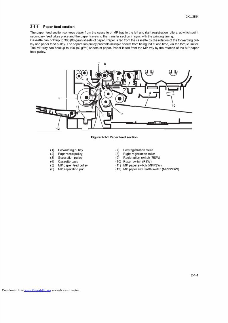
8/18/2019 taskalfa_220
http://slidepdf.com/reader/full/taskalfa220 203/300
2KL/2KK
2-1-1
2-1 Mechanical construction
2-1-1 Paper feed section
The paper feed section conveys paper from the cassette or MP tray to the left and right registration rollers, at which point
secondary feed takes place and the paper travels to the transfer section in sync with the printing timing.
Cassette can hold up to 300 (80 g/m2) sheets of paper. Paper is fed from the cassette by the rotation of the forwarding pul-
ley and paper feed pulley. The separation pulley prevents multiple sheets from being fed at one time, via the torque limiter.
The MP tray can hold up to 100 (80 g/m2) sheets of paper. Paper is fed from the MP tray by the rotation of the MP paper
feed pulley.
Figure 2-1-1 Paper feed section
5
12
10
29
87
1
4
36
11
(1) Forwarding pulley
(2) Paper feed pulley
(3) Separation pulley
(4) Cassette base
(5) MP paper feed pulley
(6) MP separation pad
(7) Left registration roller
(8) Right registration roller
(9) Registration switch (RSW)
(10) Paper switch (PSW)
(11) MP paper switch (MPPSW)
(12) MP paper size width switch (MPPWSW)
loaded from www.Manualslib.com manuals search engine
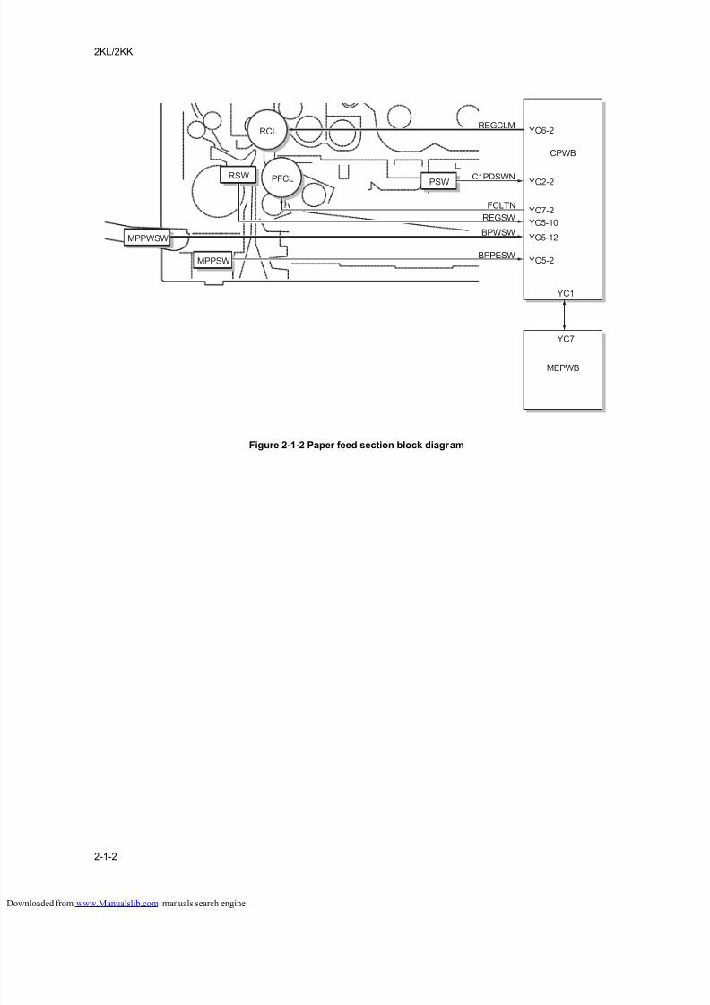
8/18/2019 taskalfa_220
http://slidepdf.com/reader/full/taskalfa220 204/300
2KL/2KK
2-1-2
Figure 2-1-2 Paper feed section block diagram
RSW PSW
MPPSW
MPPWSW
RCLREGCLM
C1PDSWN
BPWSW
BPPESW
YC7
YC1
MEPWB
CPWB
FCLTN
REGSW
YC6-2
YC2-2
YC5-12
YC5-2
YC7-2
YC5-10
PFCL
loaded from www.Manualslib.com manuals search engine
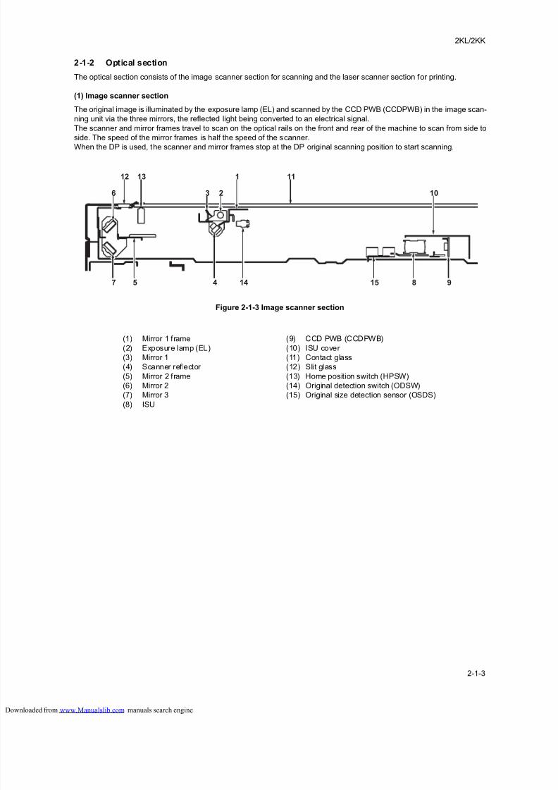
8/18/2019 taskalfa_220
http://slidepdf.com/reader/full/taskalfa220 205/300
2KL/2KK
2-1-3
2-1-2 Optical section
The optical section consists of the image scanner section for scanning and the laser scanner section for printing.
(1) Image scanner section
The original image is illuminated by the exposure lamp (EL) and scanned by the CCD PWB (CCDPWB) in the image scan-
ning unit via the three mirrors, the reflected light being converted to an electrical signal.
The scanner and mirror frames travel to scan on the optical rails on the front and rear of the machine to scan from side to
side. The speed of the mirror frames is half the speed of the scanner.When the DP is used, the scanner and mirror frames stop at the DP original scanning position to start scanning.
Figure 2-1-3 Image scanner section
7 5
6 2 103
12 13 111
4 14 815 9
(1) Mirror 1 frame
(2) Exposure lamp (EL)
(3) Mirror 1
(4) Scanner reflector
(5) Mirror 2 frame
(6) Mirror 2
(7) Mirror 3
(8) ISU
(9) CCD PWB (CCDPWB)
(10) ISU cover
(11) Contact glass
(12) Slit glass
(13) Home position switch (HPSW)
(14) Original detection switch (ODSW)
(15) Original size detection sensor (OSDS)
loaded from www.Manualslib.com manuals search engine
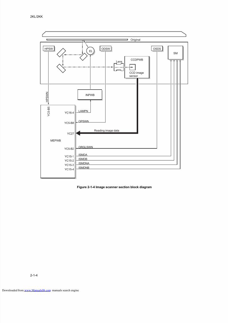
8/18/2019 taskalfa_220
http://slidepdf.com/reader/full/taskalfa220 206/300
2KL/2KK
2-1-4
Figure 2-1-4 Image scanner section block diagram
ELHPSW
H P S W N
ODSW OSDS
SM
CCDPWB
Y C
5 - B 5
OPSWN
ORGLSWN
YC5-B8
YC27
LAMPNYC16-4
YC5-B2
ISMDAYC15-1
ISMDBYC15-2
ISMDNAYC15-3
ISMDNBYC15-4
CCDPWB
INPWB
MEPWB
Original
Reading image data
Lens
CCD imagesensor
loaded from www.Manualslib.com manuals search engine
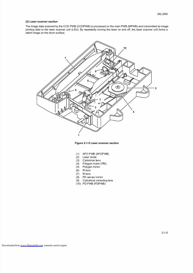
8/18/2019 taskalfa_220
http://slidepdf.com/reader/full/taskalfa220 207/300
2KL/2KK
2-1-5
(2) Laser scanner section
The image data scanned by the CCD PWB (CCDPWB) is processed on the main PWB (MPWB) and transmitted as image
printing data to the laser scanner unit (LSU). By repeatedly turning the laser on and off, the laser scanner unit forms a
latent image on the drum surface.
Figure 2-1-5 Laser scanner section
7
8
3
2
9
5
4
1
10
6
(1) APC PWB (APCPWB)
(2) Laser diode
(3) Cylindrical lens
(4) Polygon motor (PM)
(5) Polygon mirror
(6) f θ lens
(7) f θ lens
(8) PD sensor mirror
(9) Cylindrical correcting lens
(10) PD PWB (PDPWB)
loaded from www.Manualslib.com manuals search engine
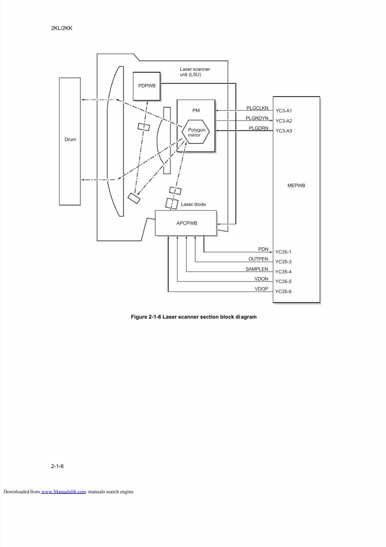
8/18/2019 taskalfa_220
http://slidepdf.com/reader/full/taskalfa220 208/300
2KL/2KK
2-1-6
Figure 2-1-6 Laser scanner section block diagram
PMPLGCLKN
PLGDRN
PLGRDYN
PDPWB
OUTPEN
PDN
SAMPLEN
VDON
VDOP
APCPWB
YC3-A1
YC3-A3
YC3-A2
MEPWB
YC35-3
YC35-1
YC35-4
YC35-5
YC35-6
Laser scanner unit (LSU)
Drum
Laser diode
Polygonmirror
loaded from www.Manualslib.com manuals search engine
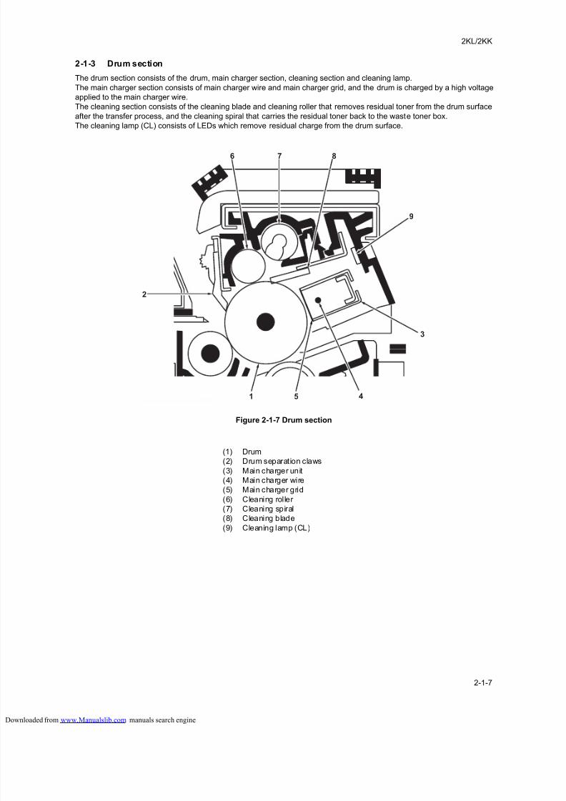
8/18/2019 taskalfa_220
http://slidepdf.com/reader/full/taskalfa220 209/300
2KL/2KK
2-1-7
2-1-3 Drum section
The drum section consists of the drum, main charger section, cleaning section and cleaning lamp.
The main charger section consists of main charger wire and main charger grid, and the drum is charged by a high voltage
applied to the main charger wire.
The cleaning section consists of the cleaning blade and cleaning roller that removes residual toner from the drum surface
after the transfer process, and the cleaning spiral that carries the residual toner back to the waste toner box.
The cleaning lamp (CL) consists of LEDs which remove residual charge from the drum surface.
Figure 2-1-7 Drum section
2
6 7 8
9
3
1 5 4
(1) Drum
(2) Drum separation claws
(3) Main charger unit
(4) Main charger wire
(5) Main charger grid
(6) Cleaning roller
(7) Cleaning spiral
(8) Cleaning blade
(9) Cleaning lamp (CL)
loaded from www.Manualslib.com manuals search engine
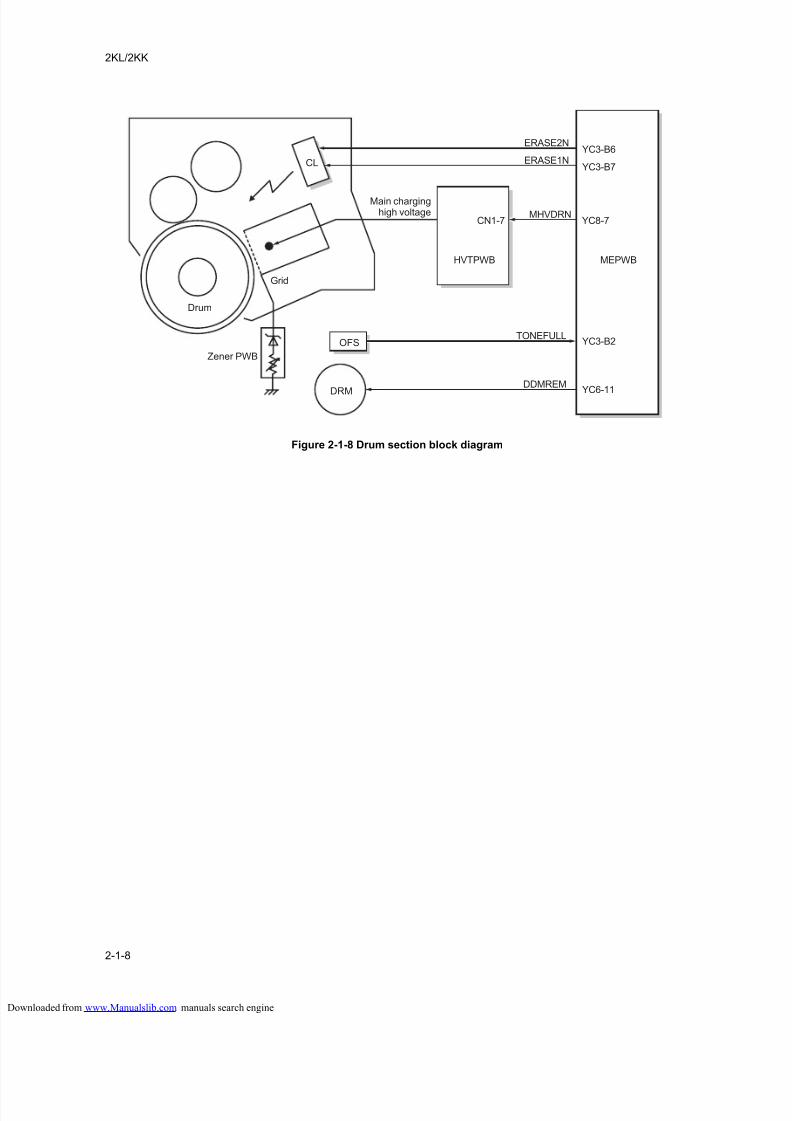
8/18/2019 taskalfa_220
http://slidepdf.com/reader/full/taskalfa220 210/300
2KL/2KK
2-1-8
Figure 2-1-8 Drum section block diagram
DRM
TONEFULL
DDMREM
YC3-B2
YC6-11
OFS
HVTPWB MEPWB
MHVDRNCN1-7 YC8-7
CL
ERASE2N
ERASE1NYC3-B6
YC3-B7
Main charginghigh voltage
Drum
Zener PWB
Grid
loaded from www.Manualslib.com manuals search engine
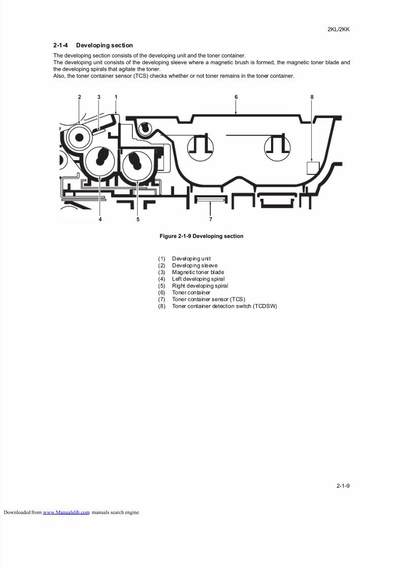
8/18/2019 taskalfa_220
http://slidepdf.com/reader/full/taskalfa220 211/300
2KL/2KK
2-1-9
2-1-4 Developing section
The developing section consists of the developing unit and the toner container.
The developing unit consists of the developing sleeve where a magnetic brush is formed, the magnetic toner blade and
the developing spirals that agitate the toner.
Also, the toner container sensor (TCS) checks whether or not toner remains in the toner container.
Figure 2-1-9 Developing section
2
4 5 7
3 1 6 8
(1) Developing unit
(2) Developing sleeve
(3) Magnetic toner blade
(4) Left developing spiral
(5) Right developing spiral
(6) Toner container
(7) Toner container sensor (TCS)(8) Toner container detection switch (TCDSW)
loaded from www.Manualslib.com manuals search engine
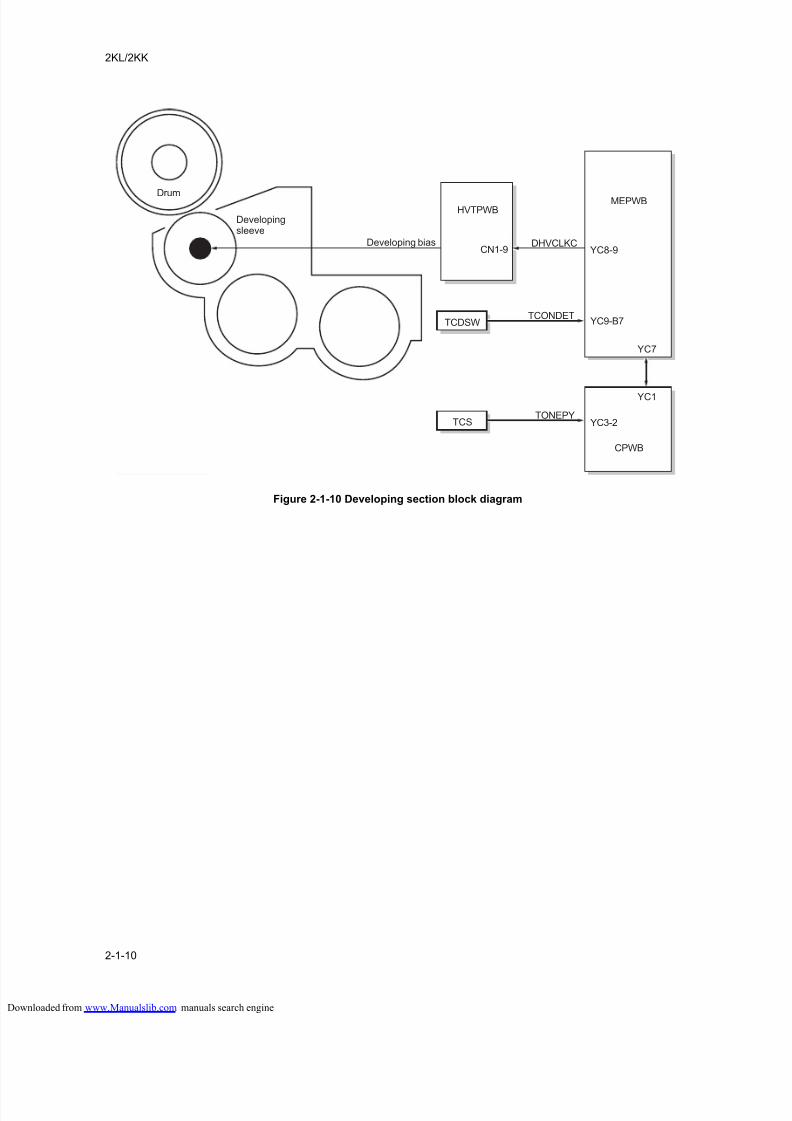
8/18/2019 taskalfa_220
http://slidepdf.com/reader/full/taskalfa220 212/300
2KL/2KK
2-1-10
Figure 2-1-10 Developing section block diagram
TCONDETYC9-B7
YC3-2
YC1
YC7
TCDSW
TONEPYTCS
HVTPWBMEPWB
CPWB
CN1-9DHVCLKC
YC8-9
Drum
Developingsleeve
Developing bias
loaded from www.Manualslib.com manuals search engine
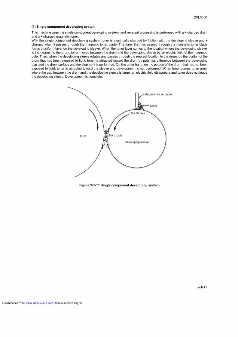
8/18/2019 taskalfa_220
http://slidepdf.com/reader/full/taskalfa220 213/300
2KL/2KK
2-1-11
(1) Single component developing system
This machine uses the single component developing system, and reversal processing is performed with a + charged drum
and a + charged magnetic toner.
With the single component developing system, toner is electrically charged by friction with the developing sleeve and +
charged when it passes through the magnetic toner blade. The toner that has passed through the magnetic toner blade
forms a uniform layer on the developing sleeve. When the toner layer comes to the location where the developing sleeve
is the nearest to the drum, toner moves between the drum and the developing sleeve by an electric field of the magnetic
pole. Then, when the developing sleeve rotates and passes through the nearest location to the drum, on the portion of the
drum that has been exposed to light, toner is attracted toward the drum by potential difference between the developing
bias and the drum surface and development is performed. On the other hand, on the portion of the drum that has not been
exposed to light, toner is attracted toward the sleeve and development is not performed. When toner comes to an area
where the gap between the drum and the developing sleeve is large, an electric field disappears and toner does not leave
the developing sleeve. Development is complete.
Figure 2-1-11 Single component developing system
North pole
South pole
Developing sleeve
Drum
Magnetic toner blade
Toner
loaded from www.Manualslib.com manuals search engine
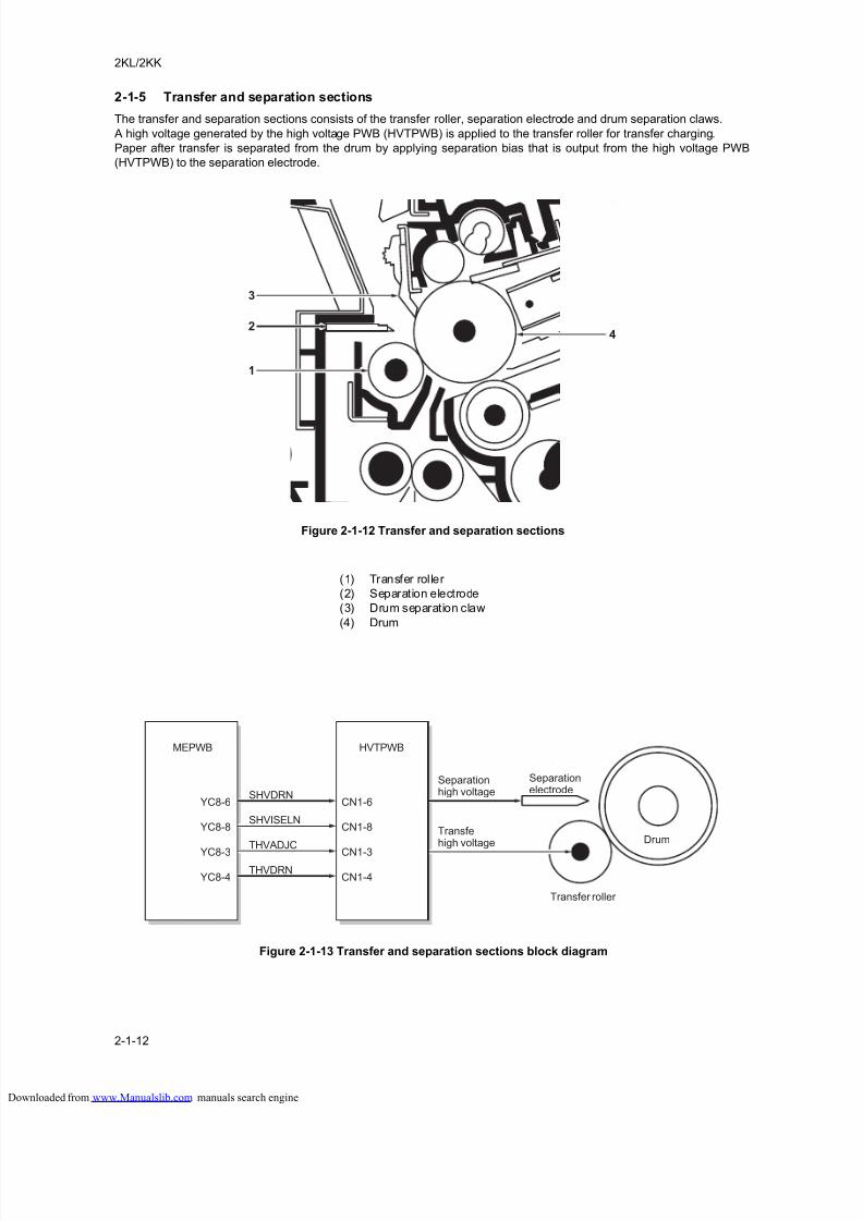
8/18/2019 taskalfa_220
http://slidepdf.com/reader/full/taskalfa220 214/300
2KL/2KK
2-1-12
2-1-5 Transfer and separation sections
The transfer and separation sections consists of the transfer roller, separation electrode and drum separation claws.
A high voltage generated by the high voltage PWB (HVTPWB) is applied to the transfer roller for transfer charging.
Paper after transfer is separated from the drum by applying separation bias that is output from the high voltage PWB
(HVTPWB) to the separation electrode.
Figure 2-1-12 Transfer and separation sections
Figure 2-1-13 Transfer and separation sections block diagram
3
2
1
4
(1) Transfer roller
(2) Separation electrode
(3) Drum separation claw
(4) Drum
Drum
Transfer roller
Separationelectrode
Separationhigh voltage
Transfehigh voltage
SHVDRN
HVTPWB
CN1-6
SHVISELNCN1-8
THVADJC
CN1-3THVDRN
CN1-4
MEPWB
YC8-6
YC8-8
YC8-3
YC8-4
loaded from www.Manualslib.com manuals search engine
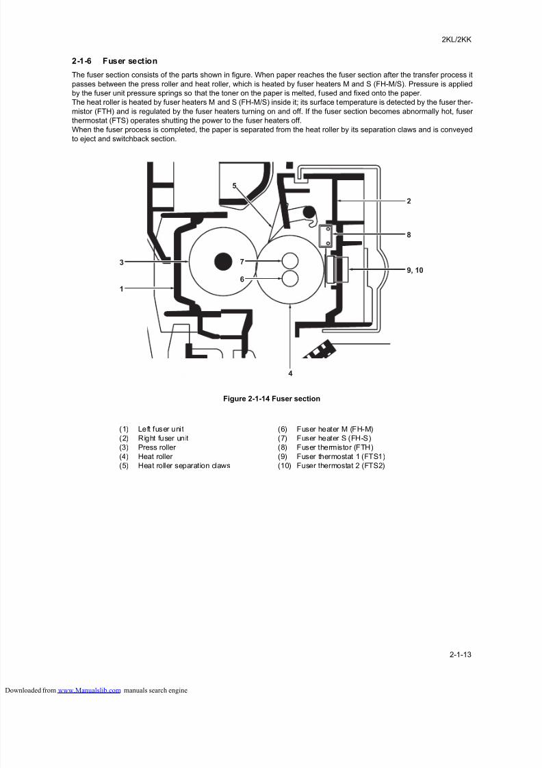
8/18/2019 taskalfa_220
http://slidepdf.com/reader/full/taskalfa220 215/300
2KL/2KK
2-1-13
2-1-6 Fuser section
The fuser section consists of the parts shown in figure. When paper reaches the fuser section after the transfer process it
passes between the press roller and heat roller, which is heated by fuser heaters M and S (FH-M/S). Pressure is applied
by the fuser unit pressure springs so that the toner on the paper is melted, fused and fixed onto the paper.
The heat roller is heated by fuser heaters M and S (FH-M/S) inside it; its surface temperature is detected by the fuser ther-
mistor (FTH) and is regulated by the fuser heaters turning on and off. If the fuser section becomes abnormally hot, fuser
thermostat (FTS) operates shutting the power to the fuser heaters off.
When the fuser process is completed, the paper is separated from the heat roller by its separation claws and is conveyed
to eject and switchback section.
Figure 2-1-14 Fuser section
3
1
6
7
5
4
9, 10
8
2
(1) Left fuser unit
(2) Right fuser unit
(3) Press roller
(4) Heat roller
(5) Heat roller separation claws
(6) Fuser heater M (FH-M)
(7) Fuser heater S (FH-S)
(8) Fuser thermistor (FTH)
(9) Fuser thermostat 1 (FTS1)
(10) Fuser thermostat 2 (FTS2)
loaded from www.Manualslib.com manuals search engine
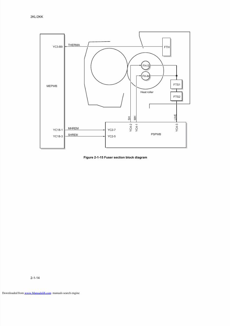
8/18/2019 taskalfa_220
http://slidepdf.com/reader/full/taskalfa220 216/300
2KL/2KK
2-1-14
Figure 2-1-15 Fuser section block diagram
FTS1
THERMA
Heat roller
FH-M
FH-S
S H
M H
L I V E
FTS2
FTH
MHREM
SHREM
YC3-B9
MEPWB
YC18-1
YC18-3PSPWB
Y C 4 - 2
Y C 4 - 1
Y C 4 - 3
YC2-7
YC2-5
loaded from www.Manualslib.com manuals search engine
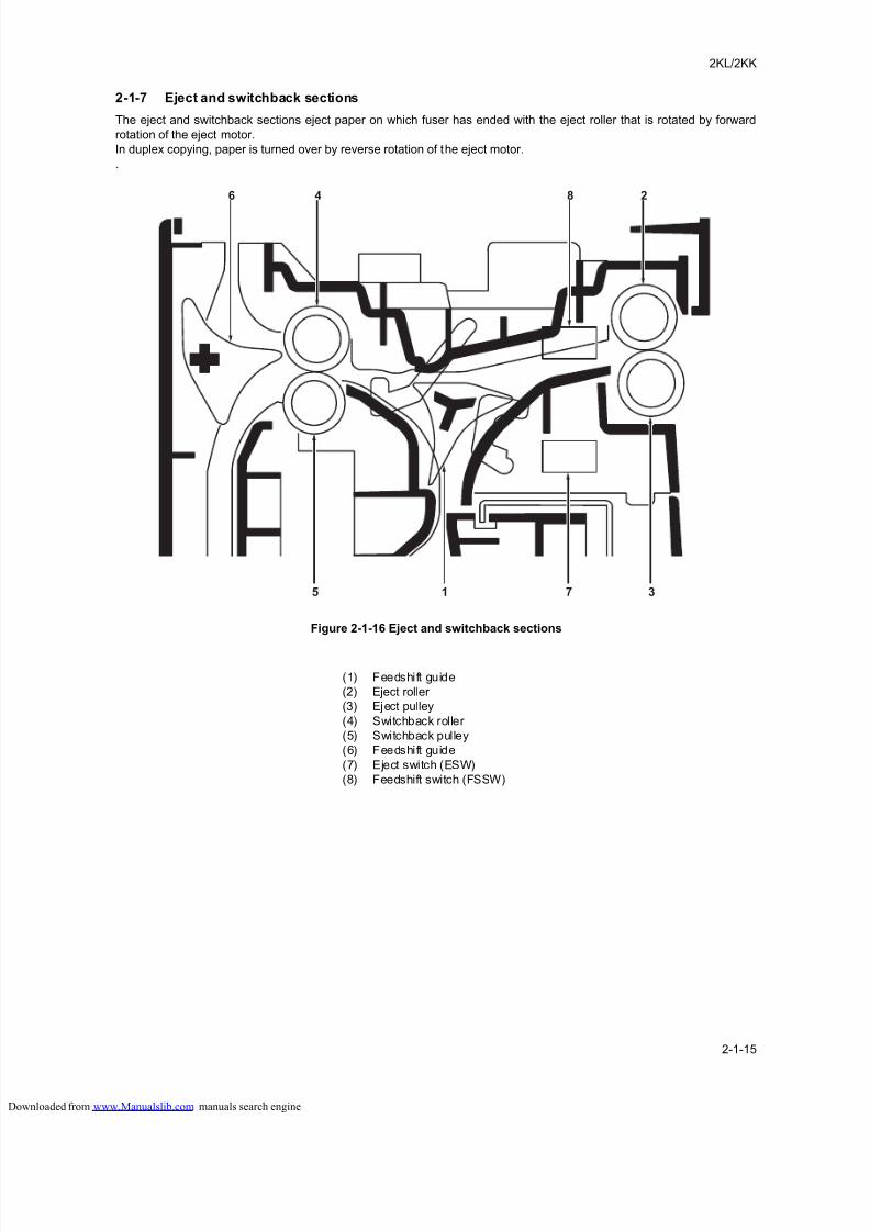
8/18/2019 taskalfa_220
http://slidepdf.com/reader/full/taskalfa220 217/300
2KL/2KK
2-1-15
2-1-7 Eject and switchback sections
The eject and switchback sections eject paper on which fuser has ended with the eject roller that is rotated by forward
rotation of the eject motor.
In duplex copying, paper is turned over by reverse rotation of the eject motor.
.
Figure 2-1-16 Eject and switchback sections
5 1 7 3
846 2
(1) Feedshift guide
(2) Eject roller
(3) Eject pulley
(4) Switchback roller
(5) Switchback pulley
(6) Feedshift guide
(7) Eject switch (ESW)
(8) Feedshift switch (FSSW)
loaded from www.Manualslib.com manuals search engine
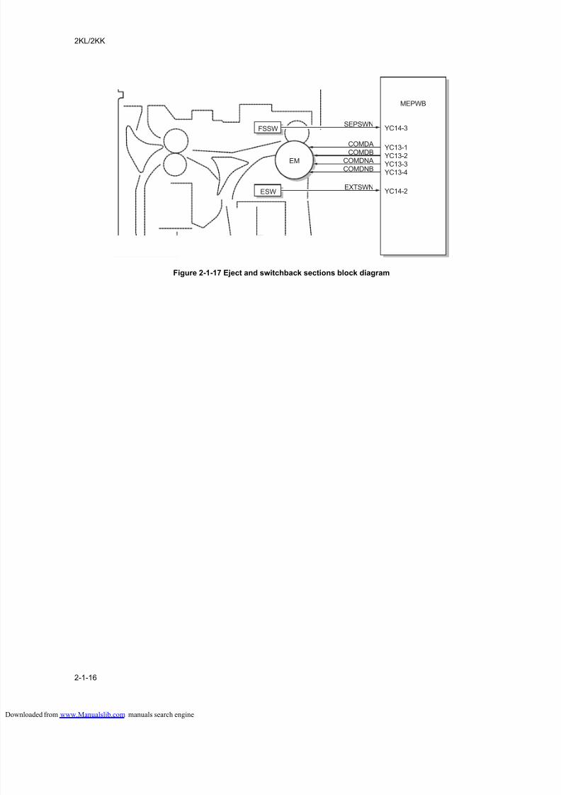
8/18/2019 taskalfa_220
http://slidepdf.com/reader/full/taskalfa220 218/300
2KL/2KK
2-1-16
Figure 2-1-17 Eject and switchback sections block diagram
FSSWSEPSWN
YC14-3
MEPWB
ESWEXTSWN
YC14-2
EM
COMDB
COMDA
COMDNB
COMDNAYC13-2
YC13-1
YC13-4
YC13-3
loaded from www.Manualslib.com manuals search engine
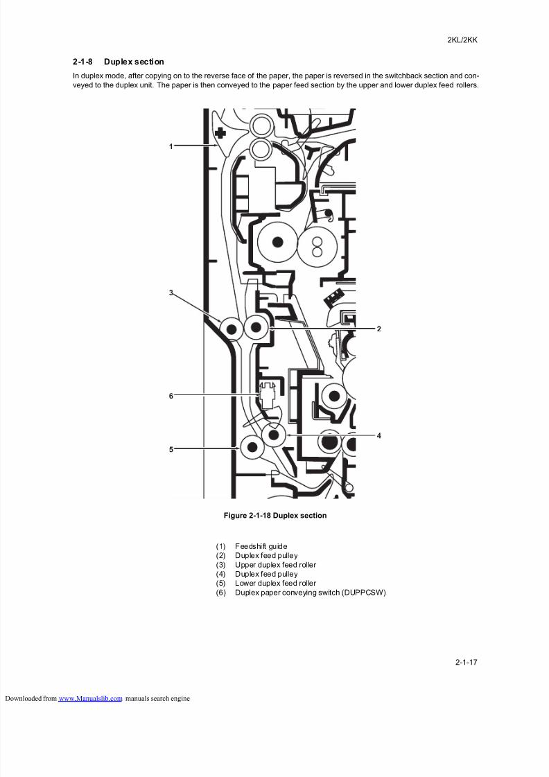
8/18/2019 taskalfa_220
http://slidepdf.com/reader/full/taskalfa220 219/300
2KL/2KK
2-1-17
2-1-8 Duplex section
In duplex mode, after copying on to the reverse face of the paper, the paper is reversed in the switchback section and con-
veyed to the duplex unit. The paper is then conveyed to the paper feed section by the upper and lower duplex feed rollers.
Figure 2-1-18 Duplex section
1
3
5
6
4
2
(1) Feedshift guide(2) Duplex feed pulley
(3) Upper duplex feed roller
(4) Duplex feed pulley
(5) Lower duplex feed roller
(6) Duplex paper conveying switch (DUPPCSW)
loaded from www.Manualslib.com manuals search engine
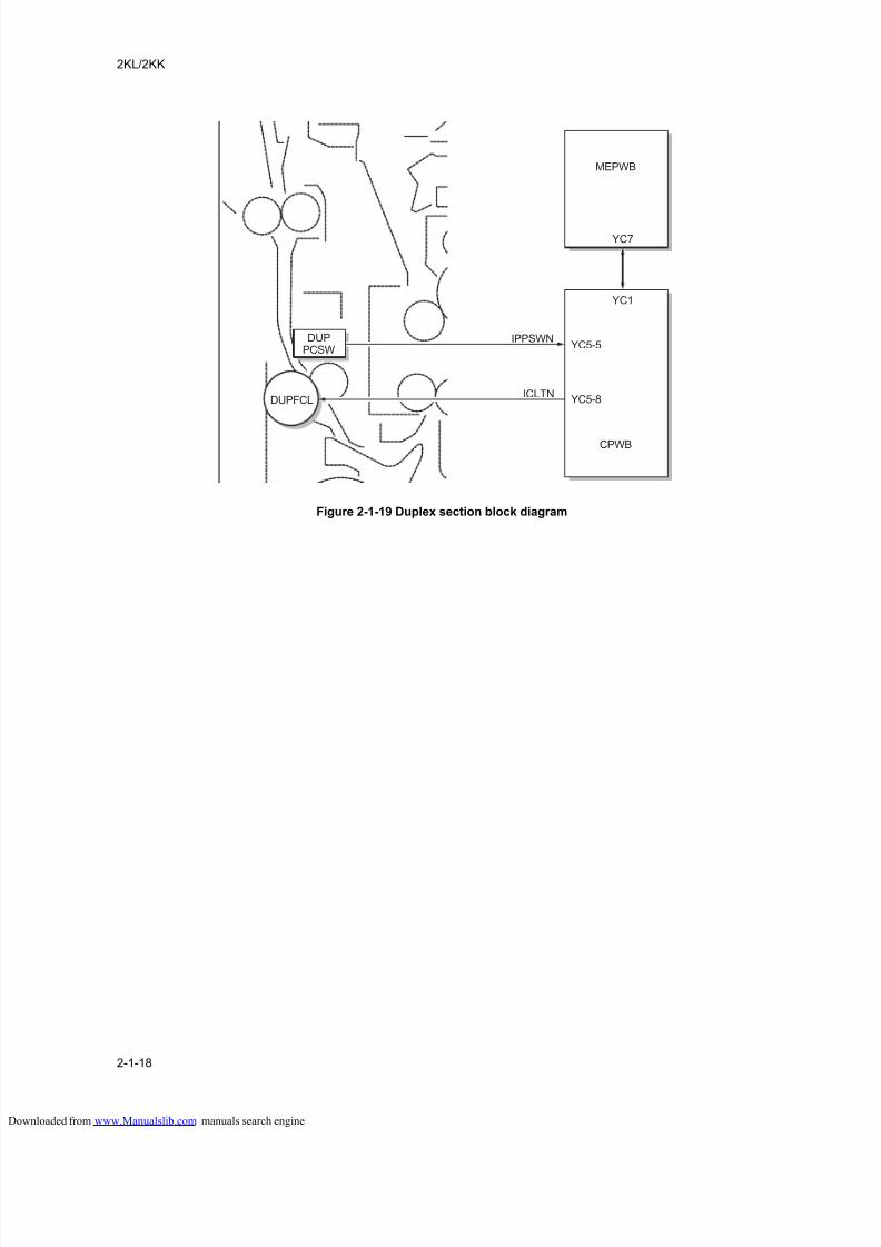
8/18/2019 taskalfa_220
http://slidepdf.com/reader/full/taskalfa220 220/300
2KL/2KK
2-1-18
Figure 2-1-19 Duplex section block diagram
CPWB
DUPPCSW
IPPSWNYC5-5
YC1
YC7
DUPFCLICLTN
YC5-8
MEPWB
loaded from www.Manualslib.com manuals search engine
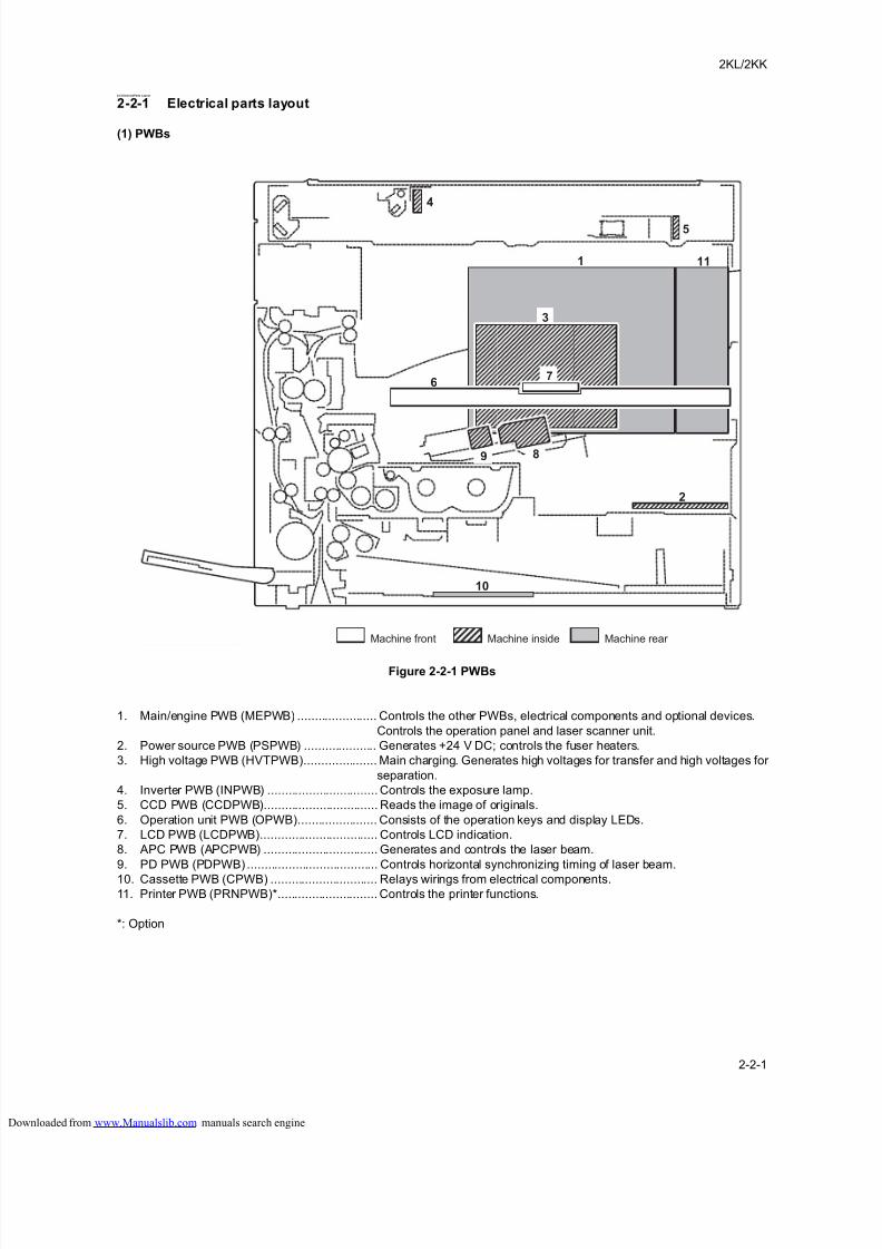
8/18/2019 taskalfa_220
http://slidepdf.com/reader/full/taskalfa220 221/300
2KL/2KK
2-2-1
2-2 ElectricalParts Layout
2-2-1 Electrical parts layout
(1) PWBs
Figure 2-2-1 PWBs
1. Main/engine PWB (MEPWB) ....................... Controls the other PWBs, electrical components and optional devices.
Controls the operation panel and laser scanner unit.
2. Power source PWB (PSPWB) ..................... Generates +24 V DC; controls the fuser heaters.
3. High voltage PWB (HVTPWB)..................... Main charging. Generates high voltages for transfer and high voltages for
separation.
4. Inverter PWB (INPWB) ................................ Controls the exposure lamp.
5. CCD PWB (CCDPWB)................................. Reads the image of originals.
6. Operation unit PWB (OPWB)....................... Consists of the operation keys and display LEDs.
7. LCD PWB (LCDPWB).................................. Controls LCD indication.
8. APC PWB (APCPWB) ................................. Generates and controls the laser beam.
9. PD PWB (PDPWB) ...................................... Controls horizontal synchronizing timing of laser beam.
10. Cassette PWB (CPWB) ............................... Relays wirings from electrical components.11. Printer PWB (PRNPWB)*............................. Controls the printer functions.
*: Option
Machine front Machine inside Machine rear
1 11
2
10
7
3
6
9 8
4
5
loaded from www.Manualslib.com manuals search engine
8/18/2019 taskalfa_220
http://slidepdf.com/reader/full/taskalfa220 222/300
2KL/2KK
2-2-2
List of correspondences of PWB names
No. Name used in service manual Name used in parts list
1 Main/engine PWB (MEPWB) PARTS PWB MAIN ENGINE ASSY SP
2 Power source PWB (PSPWB) PARTS LVU100(M) SP / PARTS LVU200(M) SP
3 High voltage PWB (HVPWB) PARTS HVU SP
4 Inverter PWB (INPWB) PARTS LAMP INVERTER SP
5 CCD PWB (CCDPWB) -
6 Operation PWB (OPWB) PARTS PWB PANEL ASSY SP
7 LCD PWB (LCDPWB) PARTS LCD OPERATION SP
8 APC PWB (APCPWB) -
9 PD PWB (PDPWB) -
10 Cassette PWB (CPWB) PARTS PWB INTERFACE ASSY SP
11 Printer PWB (PRNPWB) PARTS GDI PWB ASSY SP
loaded from www.Manualslib.com manuals search engine
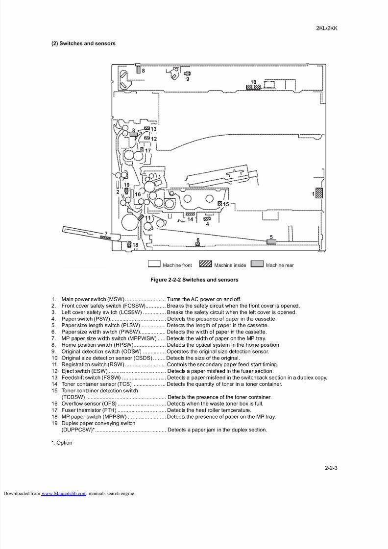
8/18/2019 taskalfa_220
http://slidepdf.com/reader/full/taskalfa220 223/300
2KL/2KK
2-2-3
(2) Switches and sensors
Figure 2-2-2 Switches and sensors
1. Main power switch (MSW) ........................... Turns the AC power on and off.
2. Front cover safety switch (FCSSW)............. Breaks the safety circuit when the front cover is opened.
3. Left cover safety switch (LCSSW) ............... Breaks the safety circuit when the left cover is opened.
4. Paper switch (PSW)..................................... Detects the presence of paper in the cassette.
5. Paper size length switch (PLSW) ................ Detects the length of paper in the cassette.
6. Paper size width switch (PWSW)................. Detects the width of paper in the cassette.
7. MP paper size width switch (MPPWSW) ..... Detects the width of paper on the MP tray.
8. Home position switch (HPSW)..................... Detects the optical system in the home position.
9. Original detection switch (ODSW) ............... Operates the original size detection sensor.
10. Original size detection sensor (OSDS) ........Detects the size of the original.
11. Registration switch (RSW) ........................... Controls the secondary paper feed start timing.
12. Eject switch (ESW) ...................................... Detects a paper misfeed in the fuser section.
13. Feedshift switch (FSSW) ............................. Detects a paper misfeed in the switchback section in a duplex copy.
14. Toner container sensor (TCS)................... ... Detects the quantity of toner in a toner container.15. Toner container detection switch
(TCDSW) ................... .................... .............. Detects the presence of the toner container.
16. Overflow sensor (OFS) ................................ Detects when the waste toner box is full.
17. Fuser thermistor (FTH) ................................ Detects the heat roller temperature.
18. MP paper switch (MPPSW) ......................... Detects the presence of paper on the MP tray.
19. Duplex paper conveying switch
(DUPPCSW)*.................. ................... .......... Detects a paper jam in the duplex section.
*: Option
1
13
14
15
12
2 16
11
17
18
19
10
7
3
6
9
8
4
5
Machine front Machine inside Machine rear
loaded from www.Manualslib.com manuals search engine
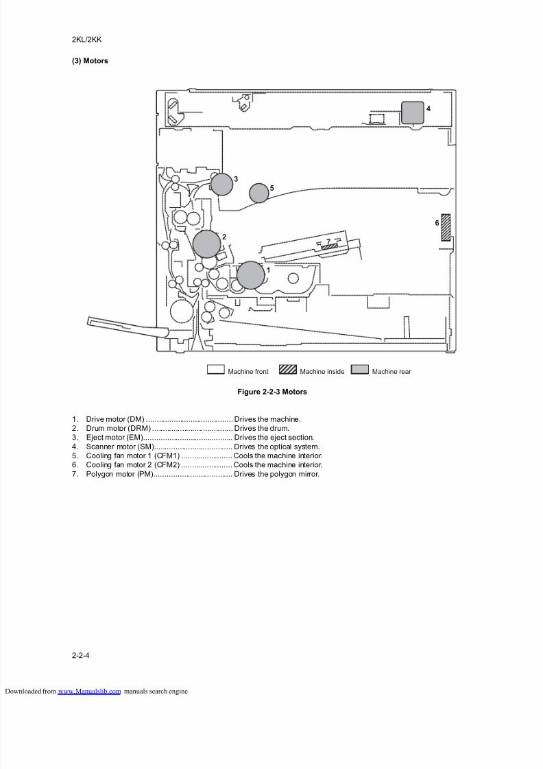
8/18/2019 taskalfa_220
http://slidepdf.com/reader/full/taskalfa220 224/300
2KL/2KK
2-2-4
(3) Motors
Figure 2-2-3 Motors
1. Drive motor (DM) ......................................... Drives the machine.
2. Drum motor (DRM) ...................................... Drives the drum.
3. Eject motor (EM).......................................... Drives the eject section.
4. Scanner motor (SM)..................................... Drives the optical system.
5. Cooling fan motor 1 (CFM1) ........................ Cools the machine interior.
6. Cooling fan motor 2 (CFM2) ........................ Cools the machine interior.
7. Polygon motor (PM)..................................... Drives the polygon mirror.
2
4
1
3
7
5
6
Machine front Machine inside Machine rear
loaded from www.Manualslib.com manuals search engine
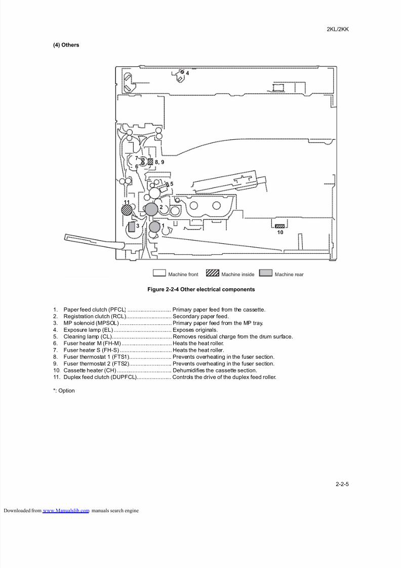
8/18/2019 taskalfa_220
http://slidepdf.com/reader/full/taskalfa220 225/300
2KL/2KK
2-2-5
(4) Others
Figure 2-2-4 Other electrical components
1. Paper feed clutch (PFCL) ............................ Primary paper feed from the cassette.
2. Registration clutch (RCL)............................. Secondary paper feed.
3. MP solenoid (MPSOL) ................................. Primary paper feed from the MP tray.
4. Exposure lamp (EL) ..................................... Exposes originals.
5. Cleaning lamp (CL)...................................... Removes residual charge from the drum surface.
6. Fuser heater M (FH-M) ................................ Heats the heat roller.
7. Fuser heater S (FH-S) ................................. Heats the heat roller.
8. Fuser thermostat 1 (FTS1)........................... Prevents overheating in the fuser section.
9. Fuser thermostat 2 (FTS2)........................... Prevents overheating in the fuser section.
10. Cassette heater (CH) ................................... Dehumidifies the cassette section.
11. Duplex feed clutch (DUPFCL)...................... Controls the drive of the duplex feed roller.
*: Option
1
5
4
2
3
6
78, 9
10
11
Machine front Machine inside Machine rear
loaded from www.Manualslib.com manuals search engine

8/18/2019 taskalfa_220
http://slidepdf.com/reader/full/taskalfa220 226/300
2KL/2KK
2-2-6
This page is intentionally left blank.
loaded from www.Manualslib.com manuals search engine
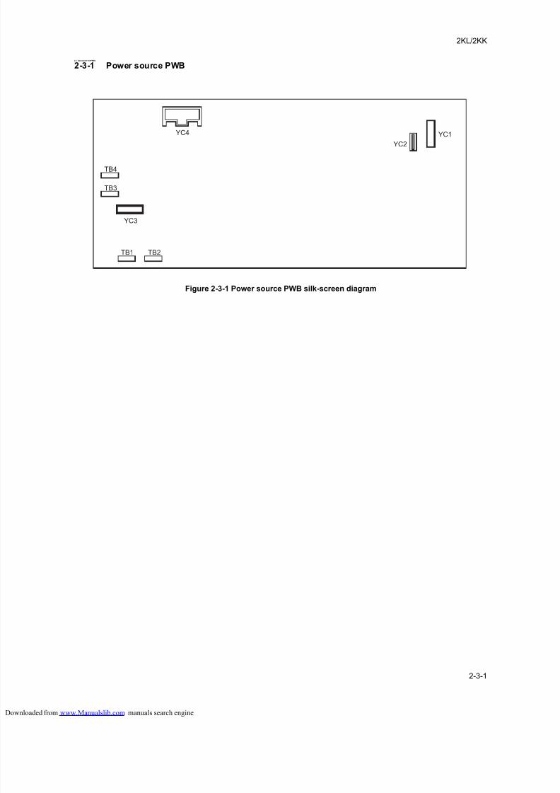
8/18/2019 taskalfa_220
http://slidepdf.com/reader/full/taskalfa220 227/300
2KL/2KK
2-3-1
2-3 Operationof thePWBs
2-3-1 Power source PWB
Figure 2-3-1 Power source PWB silk-screen diagram
YC4
YC2
YC1
YC3
TB1
TB3
TB4
TB2
loaded from www.Manualslib.com manuals search engine
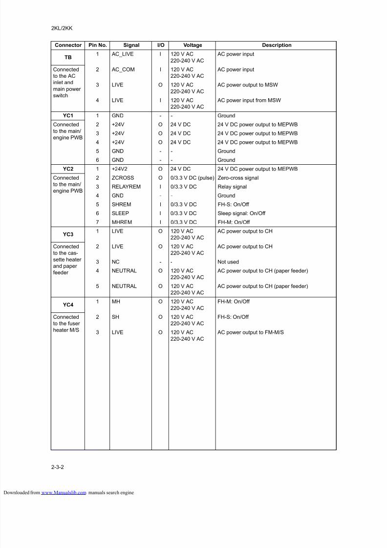
8/18/2019 taskalfa_220
http://slidepdf.com/reader/full/taskalfa220 228/300
2KL/2KK
2-3-2
Connector Pin No. Signal I/O Voltage Description
TB1 AC_LIVE I 120 V AC
220-240 V AC
AC power input
Connected
to the AC
inlet and
main power
switch
2 AC_COM I 120 V AC
220-240 V AC
AC power input
3 LIVE O 120 V AC
220-240 V AC
AC power output to MSW
4 LIVE I 120 V AC
220-240 V AC
AC power input from MSW
YC1 1 GND - - Ground
Connected
to the main/
engine PWB
2 +24V O 24 V DC 24 V DC power output to MEPWB
3 +24V O 24 V DC 24 V DC power output to MEPWB
4 +24V O 24 V DC 24 V DC power output to MEPWB
5 GND - - Ground
6 GND - - Ground
YC2 1 +24V2 O 24 V DC 24 V DC power output to MEPWB
Connected
to the main/
engine PWB
2 ZCROSS O 0/3.3 V DC (pulse) Zero-cross signal
3 RELAYREM I 0/3.3 V DC Relay signal
4 GND - - Ground
5 SHREM I 0/3.3 V DC FH-S: On/Off
6 SLEEP I 0/3.3 V DC Sleep signal: On/Off
7 MHREM I 0/3.3 V DC FH-M: On/Off
YC31 LIVE O 120 V AC
220-240 V AC
AC power output to CH
Connected
to the cas-
sette heater
and paper
feeder
2 LIVE O 120 V AC
220-240 V AC
AC power output to CH
3 NC - - Not used
4 NEUTRAL O 120 V AC
220-240 V AC
AC power output to CH (paper feeder)
5 NEUTRAL O 120 V AC220-240 V AC AC power output to CH (paper feeder)
YC41 MH O 120 V AC
220-240 V AC
FH-M: On/Off
Connected
to the fuser
heater M/S
2 SH O 120 V AC
220-240 V AC
FH-S: On/Off
3 LIVE O 120 V AC
220-240 V AC
AC power output to FM-M/S
loaded from www.Manualslib.com manuals search engine
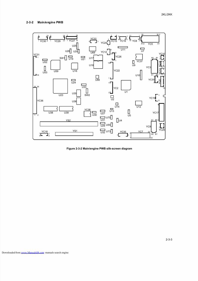
8/18/2019 taskalfa_220
http://slidepdf.com/reader/full/taskalfa220 229/300
2KL/2KK
2-3-3
2-3-2 Main/engine PWB
Figure 2-3-2 Main/engine PWB silk-screen diagram
YC30 YC29 YC27YC33
YC15YC24
YC12
YC26
YC22
YC2
YC16 YC8
YC5
YC10
Y C 1 4
Y C 1 3
Y C 6
U7
YC37
U9
U1
U10
YC20
YC19
YC17
YC25
YC9
YC7YC35
YC3
U2
U14 U12
U5
U13
U4
U75
U55
U73
U27U30
U36
U35
U33
U24
U16
U21
U69
U17
U18
U66
U19
U26
U25
U20
SW1
U59U53
U52
YC31
YC36
U23 SW2
U39
YS2
YS1YC18
U38
YC38
U31
U29
U32
U11
B1 B12
A12 A1
1B1 A9
B9 A1
24
11
11
1
8
1 A1 B9
A9
22
231
171
25
16
1
1 9
2
1
2
15 1
1
4
15
1
14
1
1
7
15
6
1
10
11
2
1
2
4
2
2
15
16
17
1810
26
1 2
276
2B1
1
2
5
5
15
4
loaded from www.Manualslib.com manuals search engine
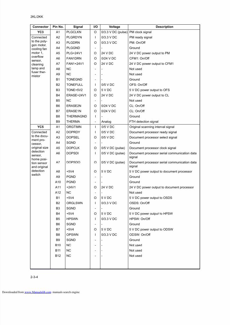
8/18/2019 taskalfa_220
http://slidepdf.com/reader/full/taskalfa220 230/300
2KL/2KK
2-3-4
Connector Pin No. Signal I/O Voltage Description
YC3 A1 PLGCLKN O 0/3.3 V DC (pulse) PM clock signal
Connected
to the poly-
gon motor,
cooling fan
motor 1,
overflowsensor,
cleaning
lamp and
fuser ther-
mistor
A2 PLGRDYN I 0/3.3 V DC PM ready signal
A3 PLGDRN O 0/3.3 V DC PM: On/Off
A4 PLGGND - - Ground
A5 PLG+24V1 O 24 V DC 24 V DC power output to PM
A6 FAN1DRN O 0/24 V DC CFM1: On/Off
A7 FAN1+24V1 O 24 V DC 24 V DC power output to CFM1
A8 NC - - Not used
A9 NC - - Not used
B1 TONEGND - - Ground
B2 TONEFULL I 0/5 V DC OFS: On/Off
B3 TONE+5V2 O 5 V DC 5 V DC power output to OFS
B4 ERASE+24V1 O 24 V DC 24 V DC power output to CL
B5 NC - - Not used
B6 ERASE2N O 0/24 V DC CL: On/Off
B7 ERASE1N O 0/24 V DC CL: On/Off
B8 THERMAGND I - Ground
B9 THERMA - Analog FTH detection signal
YC5 A1 ORGTIMN I 0/5 V DC Original scanning interval signal
Connected
to the docu-
ment pro-
cessor,
original size
detection
sensor,
home posi-
tion sensor
and original
detectionswitch
A2 DOPRDY I 0/5 V DC Document processor ready signal
A3 DOPSEL O 0/5 V DC Document processor select signal
A4 SGND - - Ground
A5 DOPCLK O 0/5 V DC (pulse) Document processor clock signal
A6 DOPSDI I 0/5 V DC (pulse) Document processor serial communication data
signal
A7 DOPSDO O 0/5 V DC (pulse) Document processor serial communication data
signal
A8 +5V4 O 5 V DC 5 V DC power output to document processor
A9 PGND - - Ground
A10 PGND - - Ground
A11 +24V1 O 24 V DC 24 V DC power output to document processor
A12 NC - - Not used
B1 +5V4 O 5 V DC 5 V DC power output to OSDS
B2 ORGLSWN I 0/3.3 V DC OSDS: On/Off
B3 SGND - - Ground
B4 +5V4 O 5 V DC 5 V DC power output to HPSW
B5 HPSWN I 0/3.3 V DC HPSW: On/Off
B6 SGND - - Ground
B7 +5V4 O 5 V DC 5 V DC power output to ODSW
B8 OPSWN I 0/3.3 V DC ODSW: On/Off
B9 SGND - - Ground
B10 NC - - Not used
B11 NC - - Not used
B12 NC - - Not used
loaded from www.Manualslib.com manuals search engine
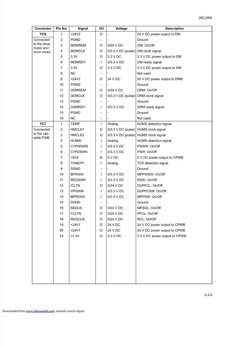
8/18/2019 taskalfa_220
http://slidepdf.com/reader/full/taskalfa220 231/300
2KL/2KK
2-3-5
YC6 1 +24V2 O - 24 V DC power output to DM
Connected
to the drive
motor and
drum motor
2 PGND - - Ground
3 MDMREM O 0/24 V DC DM: On/Off
4 MDMCLK O 0/3.3 V DC (pulse) DM clock signal
5 3.3V O 3.3 V DC 3.3 V DC power output to DM
6 MDMRDY I 0/3.3 V DC DM ready signal
7 3.3V O 3.3 V DC 3.3 V DC power output to DM
8 NC - - Not used
9 +24V2 O 24 V DC 24 V DC power output to DRM
10 PGND - - Ground
11 DDMREM O 0/24 V DC DRM: On/Off
12 DDMCLK O 0/3.3 V DC (pulse) DRM clock signal
13 PGND - - Ground
14 DDMRDY I 0/3.3 V DC DRM ready signal
15 PGND - - Ground
16 NC - - Not used
YC7 1 TEMP I Analog HUMS detection signal
Connected
to the cas-
sette PWB
2 HMCLK1 O 0/3.3 V DC (pulse) HUMS clock signal
3 HMCLK2 O 0/3.3 V DC (pulse) HUMS clock signal
4 HUMID I Analog HUMS detection signal
5 C1PWSWN I 0/3.3 V DC PWSW: On/Off
6 C1PDSWN I 0/3.3 V DC PSW: On/Off
7 +5V2 O 5 V DC 5 V DC power output to CPWB
8 TONEPY I Analog TCS detection signal
9 SGND - - Ground
10 BPWSW I 0/3.3 V DC MPPWSW: On/Off
11 REGSWN I 0/3.3 V DC RSW: On/Off
12 ICLTN O 0/24 V DC DUPFCL: On/Off
13 IPPSWN I 0/3.3 V DC DUPPCSW: On/Off
14 BPPESW I 0/3.3 V DC MPPSW: On/Off
15 SGND - - Ground
16 BSOLN O 0/24 V DC MPSOL: On/Off
17 FCLTN O 0/24 V DC PFCL: On/Off
18 REGCLN O 0/24 V DC RCL: On/Off
19 +24V1 O 24 V DC 24 V DC power output to CPWB
20 +24V1 O 24 V DC 24 V DC power output to CPWB
23 +3.3V O 3.3 V DC 3.3 V DC power output to CPWB
Connector Pin No. Signal I/O Voltage Description
loaded from www.Manualslib.com manuals search engine
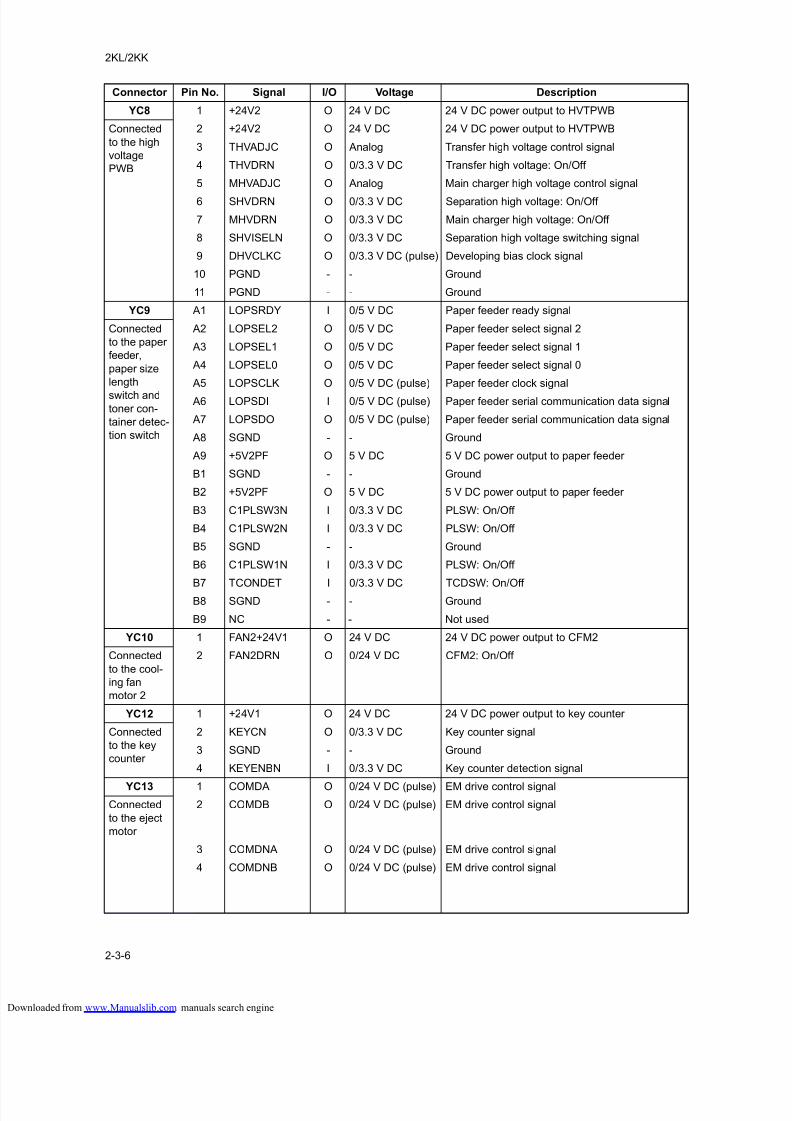
8/18/2019 taskalfa_220
http://slidepdf.com/reader/full/taskalfa220 232/300
2KL/2KK
2-3-6
YC8 1 +24V2 O 24 V DC 24 V DC power output to HVTPWB
Connected
to the high
voltage
PWB
2 +24V2 O 24 V DC 24 V DC power output to HVTPWB
3 THVADJC O Analog Transfer high voltage control signal
4 THVDRN O 0/3.3 V DC Transfer high voltage: On/Off
5 MHVADJC O Analog Main charger high voltage control signal
6 SHVDRN O 0/3.3 V DC Separation high voltage: On/Off
7 MHVDRN O 0/3.3 V DC Main charger high voltage: On/Off
8 SHVISELN O 0/3.3 V DC Separation high voltage switching signal
9 DHVCLKC O 0/3.3 V DC (pulse) Developing bias clock signal
10 PGND - - Ground
11 PGND - - Ground
YC9 A1 LOPSRDY I 0/5 V DC Paper feeder ready signal
Connected
to the paper
feeder,
paper size
length
switch andtoner con-
tainer detec-
tion switch
A2 LOPSEL2 O 0/5 V DC Paper feeder select signal 2
A3 LOPSEL1 O 0/5 V DC Paper feeder select signal 1
A4 LOPSEL0 O 0/5 V DC Paper feeder select signal 0
A5 LOPSCLK O 0/5 V DC (pulse) Paper feeder clock signal
A6 LOPSDI I 0/5 V DC (pulse) Paper feeder serial communication data signal
A7 LOPSDO O 0/5 V DC (pulse) Paper feeder serial communication data signal
A8 SGND - - Ground
A9 +5V2PF O 5 V DC 5 V DC power output to paper feeder
B1 SGND - - Ground
B2 +5V2PF O 5 V DC 5 V DC power output to paper feeder
B3 C1PLSW3N I 0/3.3 V DC PLSW: On/Off
B4 C1PLSW2N I 0/3.3 V DC PLSW: On/Off
B5 SGND - - Ground
B6 C1PLSW1N I 0/3.3 V DC PLSW: On/Off
B7 TCONDET I 0/3.3 V DC TCDSW: On/Off
B8 SGND - - Ground
B9 NC - - Not used
YC10 1 FAN2+24V1 O 24 V DC 24 V DC power output to CFM2
Connected
to the cool-
ing fan
motor 2
2 FAN2DRN O 0/24 V DC CFM2: On/Off
YC12 1 +24V1 O 24 V DC 24 V DC power output to key counter
Connected
to the key
counter
2 KEYCN O 0/3.3 V DC Key counter signal
3 SGND - - Ground
4 KEYENBN I 0/3.3 V DC Key counter detection signal
YC13 1 COMDA O 0/24 V DC (pulse) EM drive control signal
Connected
to the eject
motor
2 COMDB O 0/24 V DC (pulse) EM drive control signal
3 COMDNA O 0/24 V DC (pulse) EM drive control signal
4 COMDNB O 0/24 V DC (pulse) EM drive control signal
Connector Pin No. Signal I/O Voltage Description
loaded from www.Manualslib.com manuals search engine
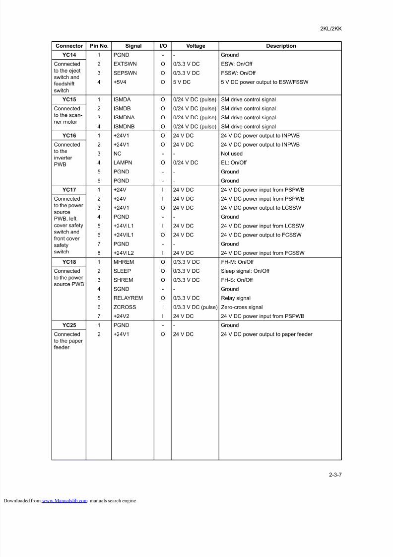
8/18/2019 taskalfa_220
http://slidepdf.com/reader/full/taskalfa220 233/300
2KL/2KK
2-3-7
YC14 1 PGND - - Ground
Connected
to the eject
switch and
feedshift
switch
2 EXTSWN O 0/3.3 V DC ESW: On/Off
3 SEPSWN O 0/3.3 V DC FSSW: On/Off
4 +5V4 O 5 V DC 5 V DC power output to ESW/FSSW
YC15 1 ISMDA O 0/24 V DC (pulse) SM drive control signal
Connected
to the scan-
ner motor
2 ISMDB O 0/24 V DC (pulse) SM drive control signal
3 ISMDNA O 0/24 V DC (pulse) SM drive control signal
4 ISMDNB O 0/24 V DC (pulse) SM drive control signal
YC16 1 +24V1 O 24 V DC 24 V DC power output to INPWB
Connected
to the
inverter
PWB
2 +24V1 O 24 V DC 24 V DC power output to INPWB
3 NC - - Not used
4 LAMPN O 0/24 V DC EL: On/Off
5 PGND - - Ground
6 PGND - - Ground
YC17 1 +24V I 24 V DC 24 V DC power input from PSPWB
Connected
to the power
source
PWB, left
cover safety
switch and
front cover
safety
switch
2 +24V I 24 V DC 24 V DC power input from PSPWB
3 +24V1 O 24 V DC 24 V DC power output to LCSSW
4 PGND - - Ground
5 +24VIL1 I 24 V DC 24 V DC power input from LCSSW
6 +24VIL1 O 24 V DC 24 V DC power output to FCSSW
7 PGND - - Ground
8 +24VIL2 I 24 V DC 24 V DC power input from FCSSW
YC18 1 MHREM O 0/3.3 V DC FH-M: On/Off
Connected
to the power
source PWB
2 SLEEP O 0/3.3 V DC Sleep signal: On/Off
3 SHREM O 0/3.3 V DC FH-S: On/Off
4 SGND - - Ground
5 RELAYREM O 0/3.3 V DC Relay signal
6 ZCROSS I 0/3.3 V DC (pulse) Zero-cross signal
7 +24V2 I 24 V DC 24 V DC power input from PSPWB
YC25 1 PGND - - Ground
Connected
to the paper
feeder
2 +24V1 O 24 V DC 24 V DC power output to paper feeder
Connector Pin No. Signal I/O Voltage Description
loaded from www.Manualslib.com manuals search engine
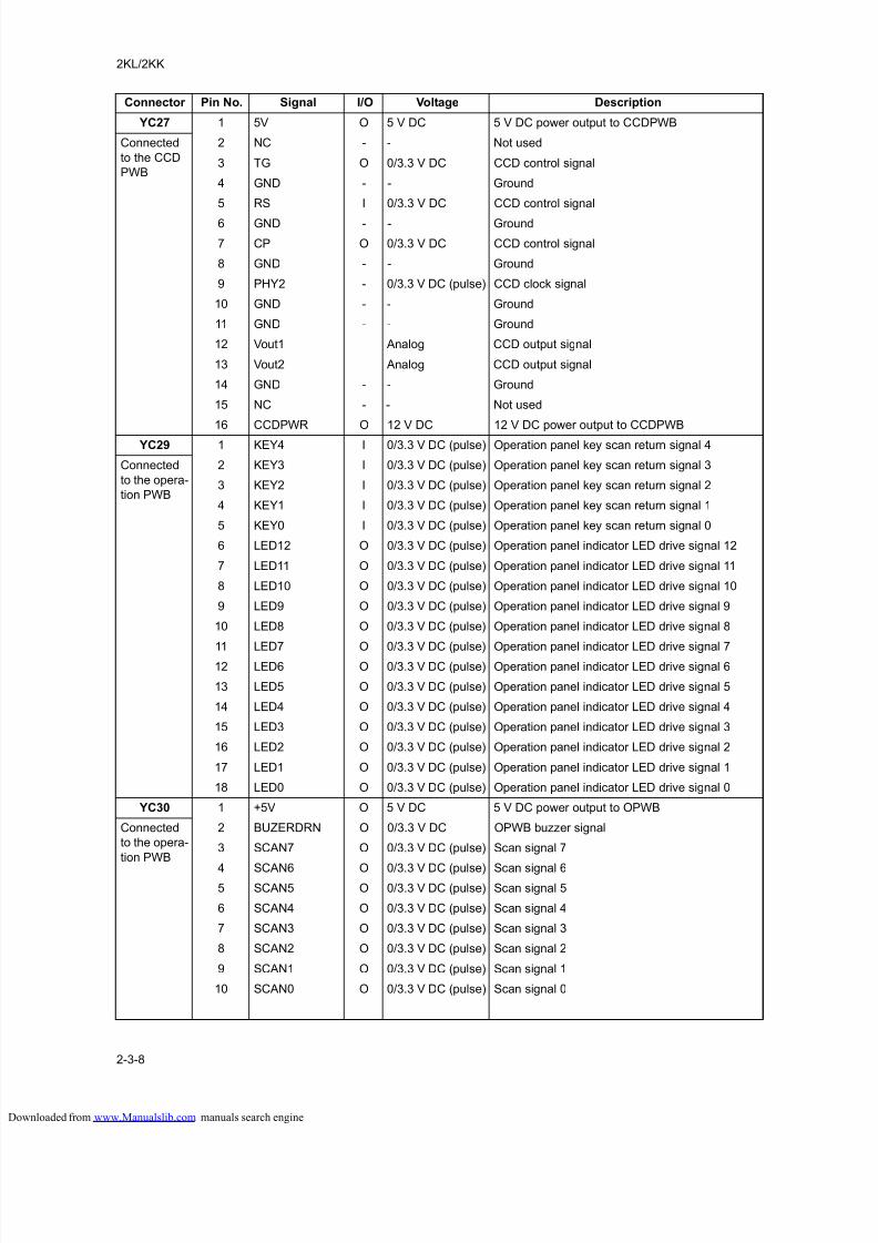
8/18/2019 taskalfa_220
http://slidepdf.com/reader/full/taskalfa220 234/300
2KL/2KK
2-3-8
YC27 1 5V O 5 V DC 5 V DC power output to CCDPWB
Connected
to the CCD
PWB
2 NC - - Not used
3 TG O 0/3.3 V DC CCD control signal
4 GND - - Ground
5 RS I 0/3.3 V DC CCD control signal
6 GND - - Ground
7 CP O 0/3.3 V DC CCD control signal
8 GND - - Ground
9 PHY2 - 0/3.3 V DC (pulse) CCD clock signal
10 GND - - Ground
11 GND - - Ground
12 Vout1 Analog CCD output signal
13 Vout2 Analog CCD output signal
14 GND - - Ground
15 NC - - Not used
16 CCDPWR O 12 V DC 12 V DC power output to CCDPWB
YC29 1 KEY4 I 0/3.3 V DC (pulse) Operation panel key scan return signal 4
Connected
to the opera-
tion PWB
2 KEY3 I 0/3.3 V DC (pulse) Operation panel key scan return signal 3
3 KEY2 I 0/3.3 V DC (pulse) Operation panel key scan return signal 2
4 KEY1 I 0/3.3 V DC (pulse) Operation panel key scan return signal 1
5 KEY0 I 0/3.3 V DC (pulse) Operation panel key scan return signal 0
6 LED12 O 0/3.3 V DC (pulse) Operation panel indicator LED drive signal 12
7 LED11 O 0/3.3 V DC (pulse) Operation panel indicator LED drive signal 11
8 LED10 O 0/3.3 V DC (pulse) Operation panel indicator LED drive signal 10
9 LED9 O 0/3.3 V DC (pulse) Operation panel indicator LED drive signal 9
10 LED8 O 0/3.3 V DC (pulse) Operation panel indicator LED drive signal 8
11 LED7 O 0/3.3 V DC (pulse) Operation panel indicator LED drive signal 7
12 LED6 O 0/3.3 V DC (pulse) Operation panel indicator LED drive signal 6
13 LED5 O 0/3.3 V DC (pulse) Operation panel indicator LED drive signal 5
14 LED4 O 0/3.3 V DC (pulse) Operation panel indicator LED drive signal 4
15 LED3 O 0/3.3 V DC (pulse) Operation panel indicator LED drive signal 3
16 LED2 O 0/3.3 V DC (pulse) Operation panel indicator LED drive signal 2
17 LED1 O 0/3.3 V DC (pulse) Operation panel indicator LED drive signal 1
18 LED0 O 0/3.3 V DC (pulse) Operation panel indicator LED drive signal 0
YC30 1 +5V O 5 V DC 5 V DC power output to OPWB
Connected
to the opera-
tion PWB
2 BUZERDRN O 0/3.3 V DC OPWB buzzer signal
3 SCAN7 O 0/3.3 V DC (pulse) Scan signal 7
4 SCAN6 O 0/3.3 V DC (pulse) Scan signal 65 SCAN5 O 0/3.3 V DC (pulse) Scan signal 5
6 SCAN4 O 0/3.3 V DC (pulse) Scan signal 4
7 SCAN3 O 0/3.3 V DC (pulse) Scan signal 3
8 SCAN2 O 0/3.3 V DC (pulse) Scan signal 2
9 SCAN1 O 0/3.3 V DC (pulse) Scan signal 1
10 SCAN0 O 0/3.3 V DC (pulse) Scan signal 0
Connector Pin No. Signal I/O Voltage Description
loaded from www.Manualslib.com manuals search engine
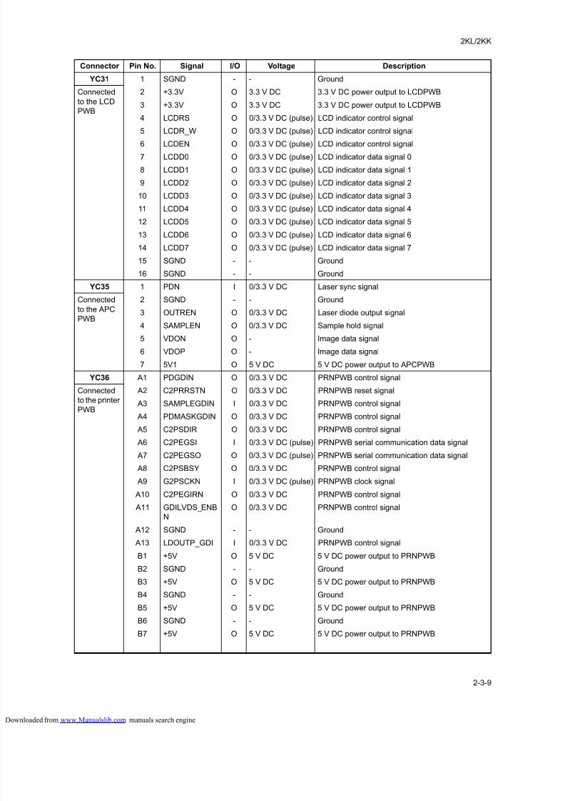
8/18/2019 taskalfa_220
http://slidepdf.com/reader/full/taskalfa220 235/300
2KL/2KK
2-3-9
YC31 1 SGND - - Ground
Connected
to the LCD
PWB
2 +3.3V O 3.3 V DC 3.3 V DC power output to LCDPWB
3 +3.3V O 3.3 V DC 3.3 V DC power output to LCDPWB
4 LCDRS O 0/3.3 V DC (pulse) LCD indicator control signal
5 LCDR_W O 0/3.3 V DC (pulse) LCD indicator control signal
6 LCDEN O 0/3.3 V DC (pulse) LCD indicator control signal
7 LCDD0 O 0/3.3 V DC (pulse) LCD indicator data signal 0
8 LCDD1 O 0/3.3 V DC (pulse) LCD indicator data signal 1
9 LCDD2 O 0/3.3 V DC (pulse) LCD indicator data signal 2
10 LCDD3 O 0/3.3 V DC (pulse) LCD indicator data signal 3
11 LCDD4 O 0/3.3 V DC (pulse) LCD indicator data signal 4
12 LCDD5 O 0/3.3 V DC (pulse) LCD indicator data signal 5
13 LCDD6 O 0/3.3 V DC (pulse) LCD indicator data signal 6
14 LCDD7 O 0/3.3 V DC (pulse) LCD indicator data signal 7
15 SGND - - Ground
16 SGND - - Ground
YC35 1 PDN I 0/3.3 V DC Laser sync signal
Connected
to the APC
PWB
2 SGND - - Ground
3 OUTREN O 0/3.3 V DC Laser diode output signal
4 SAMPLEN O 0/3.3 V DC Sample hold signal
5 VDON O - Image data signal
6 VDOP O - Image data signal
7 5V1 O 5 V DC 5 V DC power output to APCPWB
YC36 A1 PDGDIN O 0/3.3 V DC PRNPWB control signal
Connected
to the printer
PWB
A2 C2PRRSTN O 0/3.3 V DC PRNPWB reset signal
A3 SAMPLEGDIN I 0/3.3 V DC PRNPWB control signal
A4 PDMASKGDIN O 0/3.3 V DC PRNPWB control signal
A5 C2PSDIR O 0/3.3 V DC PRNPWB control signal
A6 C2PEGSI I 0/3.3 V DC (pulse) PRNPWB serial communication data signal
A7 C2PEGSO O 0/3.3 V DC (pulse) PRNPWB serial communication data signal
A8 C2PSBSY O 0/3.3 V DC PRNPWB control signal
A9 G2PSCKN I 0/3.3 V DC (pulse) PRNPWB clock signal
A10 C2PEGIRN O 0/3.3 V DC PRNPWB control signal
A11 GDILVDS_ENB
N
O 0/3.3 V DC PRNPWB control signal
A12 SGND - - Ground
A13 LDOUTP_GDI I 0/3.3 V DC PRNPWB control signal
B1 +5V O 5 V DC 5 V DC power output to PRNPWB
B2 SGND - - Ground
B3 +5V O 5 V DC 5 V DC power output to PRNPWB
B4 SGND - - Ground
B5 +5V O 5 V DC 5 V DC power output to PRNPWB
B6 SGND - - Ground
B7 +5V O 5 V DC 5 V DC power output to PRNPWB
Connector Pin No. Signal I/O Voltage Description
loaded from www.Manualslib.com manuals search engine
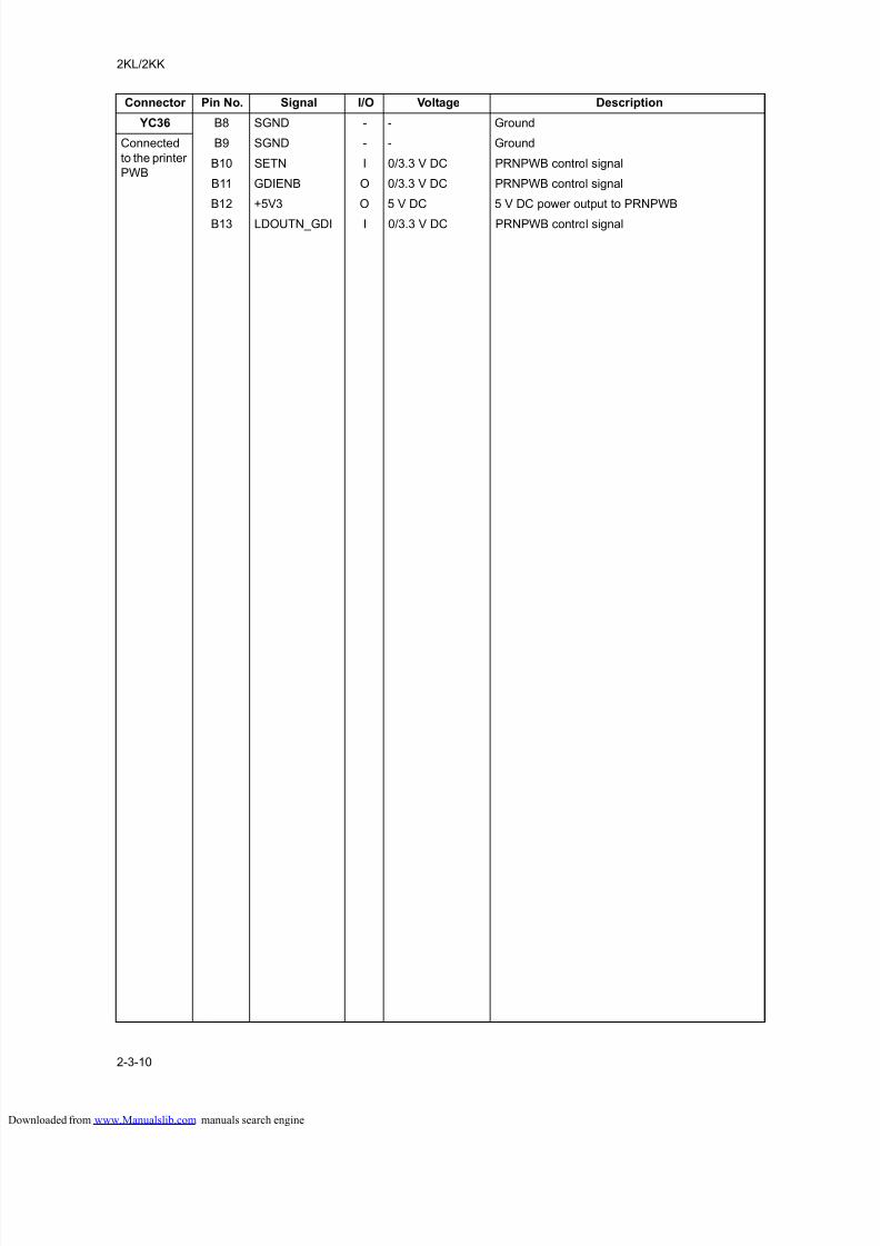
8/18/2019 taskalfa_220
http://slidepdf.com/reader/full/taskalfa220 236/300
2KL/2KK
2-3-10
YC36 B8 SGND - - Ground
Connected
to the printer
PWB
B9 SGND - - Ground
B10 SETN I 0/3.3 V DC PRNPWB control signal
B11 GDIENB O 0/3.3 V DC PRNPWB control signal
B12 +5V3 O 5 V DC 5 V DC power output to PRNPWB
B13 LDOUTN_GDI I 0/3.3 V DC PRNPWB control signal
Connector Pin No. Signal I/O Voltage Description
loaded from www.Manualslib.com manuals search engine
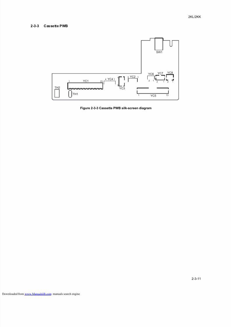
8/18/2019 taskalfa_220
http://slidepdf.com/reader/full/taskalfa220 237/300
2KL/2KK
2-3-11
2-3-3 Cassette PWB
Figure 2-3-3 Cassette PWB silk-screen diagram
YC1
TH2
TH1
YC4
YC3
YC2
YC5
YC6 YC7 YC8
SW1
1 234 1
1
3
3 1
1
2 12 1 12
13
loaded from www.Manualslib.com manuals search engine
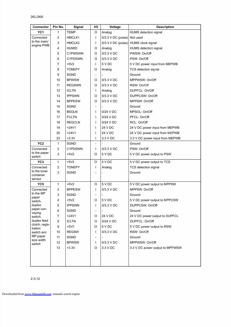
8/18/2019 taskalfa_220
http://slidepdf.com/reader/full/taskalfa220 238/300
2KL/2KK
2-3-12
Connector Pin No. Signal I/O Voltage Description
YC1 1 TEMP O Analog HUMS detection signal
Connected
to the main/
engine PWB
2 HMCLK1 I 0/3.3 V DC (pulse) Not used
3 HMCLK2 I 0/3.3 V DC (pulse) HUMS clock signal
4 HUMID O Analog HUMS detection signal
5 C1PWSWN O 0/3.3 V DC PWSW: On/Off
6 C1PDSWN O 0/3.3 V DC PSW: On/Off
7 +5V2 I 5 V DC 5 V DC power input from MEPWB
8 TONEPY O Analog TCS detection signal
9 SGND - - Ground
10 BPWSW O 0/3.3 V DC MPPWSW: On/Off
11 REGSWN O 0/3.3 V DC RSW: On/Off
12 ICLTN I Analog DUPFCL: On/Off
13 IPPSWN O 0/3.3 V DC DUPPCSW: On/Off
14 BPPESW O 0/3.3 V DC MPPSW: On/Off
15 SGND - - Ground
16 BSOLN I 0/24 V DC MPSOL: On/Off
17 FCLTN I 0/24 V DC PFCL: On/Off
18 REGCLN I 0/24 V DC RCL: On/Off
19 +24V1 I 24 V DC 24 V DC power input from MEPWB
20 +24V1 I 24 V DC 24 V DC power input from MEPWB
23 +3.3V I 3.3 V DC 3.3 V DC power input from MEPWB
YC2 1 SGND - - Ground
Connected
to the paper
switch
2 C1PDSWN I 0/3.3 V DC PSW: On/Off
3 +5V2 O 5 V DC 5 V DC power output to PSW
YC3 1 +5V2 O 5 V DC 5 V DC power output to TCS
Connected
to the tonercontainer
sensor
2 TONEPY I Analog TCS detection signal
3 SGND - - Ground
YC5 1 +5V2 O 5 V DC 5 V DC power output to MPPSW
Connected
to the MP
paper
switch,
duplex
paper con-
veying
switch,
duplex feed
clutch, regis-
trationswitch and
MP paper
size width
switch
2 BPPESW I 0/3.3 V DC MPPSW: On/Off
3 SGND - - Ground
4 +5V2 O 5 V DC 5 V DC power output to MPPCSW
5 IPPSWN I 0/3.3 V DC DUPPCSW: On/Off
6 SGND - - Ground
7 +24V1 O 24 V DC 24 V DC power output to DUPFCL
8 ICLTN O 0/24 V DC DUPFCL: On/Off
9 +5V2 O 5 V DC 5 V DC power output to RSW
10 REGSW I 0/3.3 V DC RSW: On/Off
11 SGND - - Ground
12 BPWSW I 0/3.3 V DC MPPWSW: On/Off
13 +3.3V O 3.3 V DC 3.3 V DC power output to MPPWSW
loaded from www.Manualslib.com manuals search engine
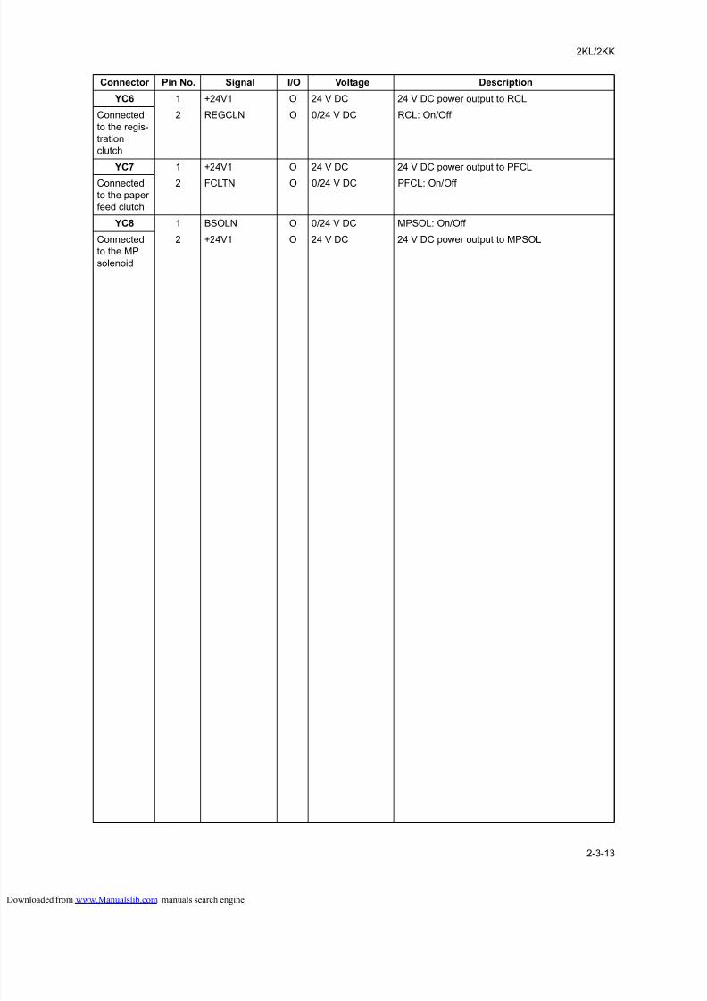
8/18/2019 taskalfa_220
http://slidepdf.com/reader/full/taskalfa220 239/300
2KL/2KK
2-3-13
YC6 1 +24V1 O 24 V DC 24 V DC power output to RCL
Connected
to the regis-
tration
clutch
2 REGCLN O 0/24 V DC RCL: On/Off
YC7 1 +24V1 O 24 V DC 24 V DC power output to PFCL
Connected
to the paper
feed clutch
2 FCLTN O 0/24 V DC PFCL: On/Off
YC8 1 BSOLN O 0/24 V DC MPSOL: On/Off
Connected
to the MP
solenoid
2 +24V1 O 24 V DC 24 V DC power output to MPSOL
Connector Pin No. Signal I/O Voltage Description
loaded from www.Manualslib.com manuals search engine
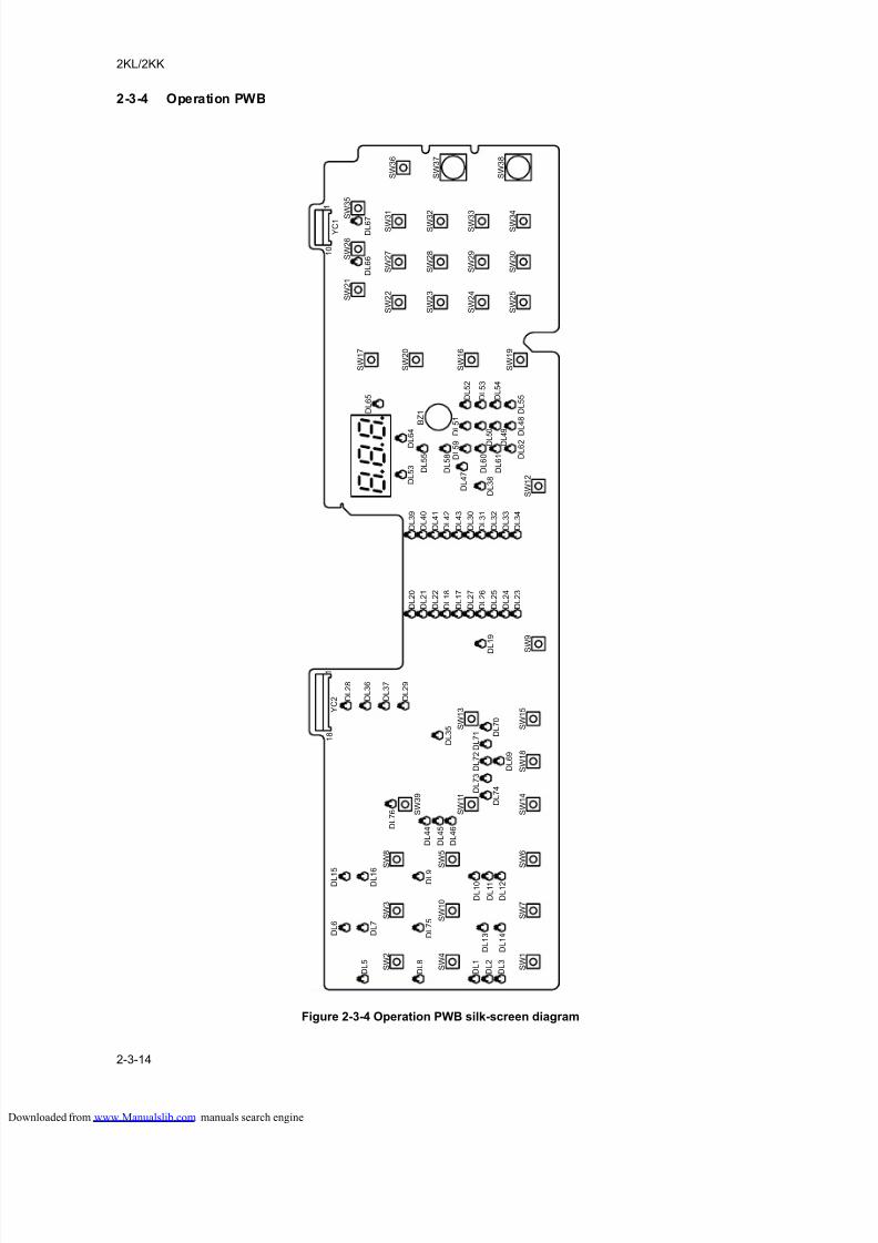
8/18/2019 taskalfa_220
http://slidepdf.com/reader/full/taskalfa220 240/300
2KL/2KK
2-3-14
2-3-4 Operation PWB
Figure 2-3-4 Operation PWB silk-screen diagram
S W 2
S W 4
S W 1
S W 3
S W 1 0
S W 7
S W 8
S W 5
S W 6
S W 3 9
Y C 2 D
L 2 8
D L 3 6
D L 3 7
D L 2 9
D L 3 5
D L 7 0
D
L 1 9
D L 2 3
D L 2 4
D L 2 5
D L 2 6
D L 2 7
D L 1 7
D L 1 8
D L 2 2
D L 2 1
D L 2 0
D L 3 4
D L 3 3
D L 3 2
D L 3 1
D L 3 0
D L 4 3
D L 4 2
D L 4 1
D L 4 0
D L 3 9
D L 3 8
D L 4 7
D L 5 3 D
L 5 5
D L 5 8 D L 5 9 D
L 5 1
D
L 4 8 D L 5 5
D L 6 2
D L 6 5
D L 6 6
D L 6 7
D L 6 0
D L 6 1
D L 5
0
D L 4
9
D L 5 3
D L 5 2
D L 5 4
D L 6
4
D L 7 4
D L 6 9
D L 7 1
D L 7 2
D L 7 3
D L 4 4 D
L 7 6
D L 9
D L 7 5
D L 8
D L 1 6
D L 7
D L 1 5
D L 6
D L 5
D L 4 5
D L 4 6
D L 1 0
D L 1 1
D L 1 2
D L 1 3
D L 1 4
D L 1
D L 2
D L 3
1 8
1
S W 1 1
S W 1 4
S W 1 3
S W 1 8
S W 1 5
S W 9
S W 1 2
S W 1 9
S W 1 6
S W 2 0
S W 1 7
S W 2 5
S W 2 4
S W 2 3
S W 2 2
S W 3 0
S W 2 9
S W 2 8
S W 2 7
S W 3
4
S W 3
3
S W 3
2
S W 3
1
S W 2 6
S
W 3 5
Y C 1
1
1 0
S W 3 6
S W 3 7
S W 3 8
S W 2 1
B Z 1
loaded from www.Manualslib.com manuals search engine
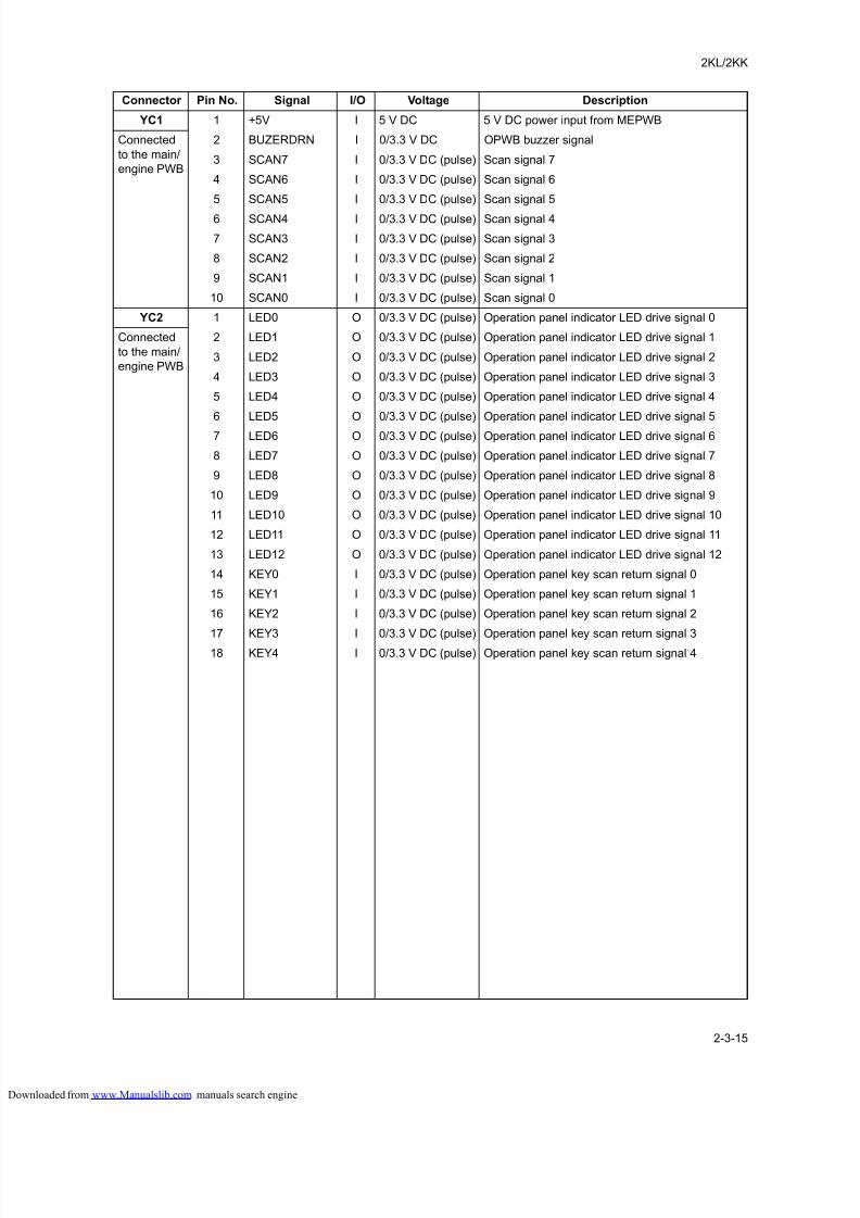
8/18/2019 taskalfa_220
http://slidepdf.com/reader/full/taskalfa220 241/300
2KL/2KK
2-3-15
Connector Pin No. Signal I/O Voltage Description
YC1 1 +5V I 5 V DC 5 V DC power input from MEPWB
Connected
to the main/
engine PWB
2 BUZERDRN I 0/3.3 V DC OPWB buzzer signal
3 SCAN7 I 0/3.3 V DC (pulse) Scan signal 7
4 SCAN6 I 0/3.3 V DC (pulse) Scan signal 6
5 SCAN5 I 0/3.3 V DC (pulse) Scan signal 5
6 SCAN4 I 0/3.3 V DC (pulse) Scan signal 4
7 SCAN3 I 0/3.3 V DC (pulse) Scan signal 3
8 SCAN2 I 0/3.3 V DC (pulse) Scan signal 2
9 SCAN1 I 0/3.3 V DC (pulse) Scan signal 1
10 SCAN0 I 0/3.3 V DC (pulse) Scan signal 0
YC2 1 LED0 O 0/3.3 V DC (pulse) Operation panel indicator LED drive signal 0
Connected
to the main/
engine PWB
2 LED1 O 0/3.3 V DC (pulse) Operation panel indicator LED drive signal 1
3 LED2 O 0/3.3 V DC (pulse) Operation panel indicator LED drive signal 2
4 LED3 O 0/3.3 V DC (pulse) Operation panel indicator LED drive signal 3
5 LED4 O 0/3.3 V DC (pulse) Operation panel indicator LED drive signal 4
6 LED5 O 0/3.3 V DC (pulse) Operation panel indicator LED drive signal 5
7 LED6 O 0/3.3 V DC (pulse) Operation panel indicator LED drive signal 6
8 LED7 O 0/3.3 V DC (pulse) Operation panel indicator LED drive signal 7
9 LED8 O 0/3.3 V DC (pulse) Operation panel indicator LED drive signal 8
10 LED9 O 0/3.3 V DC (pulse) Operation panel indicator LED drive signal 9
11 LED10 O 0/3.3 V DC (pulse) Operation panel indicator LED drive signal 10
12 LED11 O 0/3.3 V DC (pulse) Operation panel indicator LED drive signal 11
13 LED12 O 0/3.3 V DC (pulse) Operation panel indicator LED drive signal 12
14 KEY0 I 0/3.3 V DC (pulse) Operation panel key scan return signal 0
15 KEY1 I 0/3.3 V DC (pulse) Operation panel key scan return signal 1
16 KEY2 I 0/3.3 V DC (pulse) Operation panel key scan return signal 2
17 KEY3 I 0/3.3 V DC (pulse) Operation panel key scan return signal 3
18 KEY4 I 0/3.3 V DC (pulse) Operation panel key scan return signal 4
loaded from www.Manualslib.com manuals search engine

8/18/2019 taskalfa_220
http://slidepdf.com/reader/full/taskalfa220 242/300
2KL/2KK
2-3-16
This page is intentionally left blank.
loaded from www.Manualslib.com manuals search engine
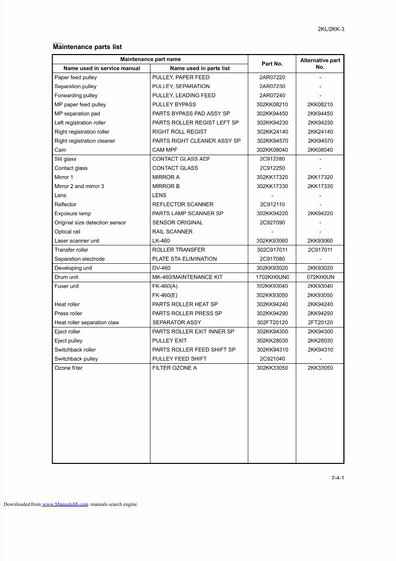
8/18/2019 taskalfa_220
http://slidepdf.com/reader/full/taskalfa220 243/300
2KL/2KK-3
2-4-1
2-4 Appendixes
Maintenance parts list
Maintenance part namePart No.
Alternative part
No.Name used in service manual Name used in parts list
Paper feed pulley PULLEY, PAPER FEED 2AR07220 -
Separation pulley PULLEY, SEPARATION 2AR07230 -
Forwarding pulley PULLEY, LEADING FEED 2AR07240 -MP paper feed pulley PULLEY BYPASS 302KK08210 2KK08210
MP separation pad PARTS BYPASS PAD ASSY SP 302KK94450 2KK94450
Left registration roller PARTS ROLLER REGIST LEFT SP 302KK94230 2KK94230
Right registration roller RIGHT ROLL REGIST 302KK24140 2KK24140
Right registration cleaner PARTS RIGHT CLEANER ASSY SP 302KK94570 2KK94570
Cam CAM MPF 302KK08040 2KK08040
Slit glass CONTACT GLASS ADF 2C912280 -
Contact glass CONTACT GLASS 2C912250 -
Mirror 1 MIRROR A 302KK17320 2KK17320
Mirror 2 and mirror 3 MIRROR B 302KK17330 2KK17330
Lens LENS - -Reflector REFLECTOR SCANNER 2C912110 -
Exposure lamp PARTS LAMP SCANNER SP 302KK94220 2KK94220
Original size detection sensor SENSOR ORIGINAL 2C927090 -
Optical rail RAIL SCANNER - -
Laser scanner unit LK-460 302KK93060 2KK93060
Transfer roller ROLLER TRANSFER 302C917011 2C917011
Separation electrode PLATE STA ELIMINATION 2C917080 -
Developing unit DV-460 302KK93020 2KK93020
Drum unit MK-460/MAINTENANCE KIT 1702KH0UN0 072KH0UN
Fuser unit FK-460(A) 302KK93040 2KK93040
FK-460(E) 302KK93050 2KK93050
Heat roller PARTS ROLLER HEAT SP 302KK94240 2KK94240
Press roller PARTS ROLLER PRESS SP 302KK94290 2KK94290
Heat roller separation claw SEPARATOR ASSY 302FT20120 2FT20120
Eject roller PARTS ROLLER EXIT INNER SP 302KK94300 2KK94300
Eject pulley PULLEY EXIT 302KK28030 2KK28030
Switchback roller PARTS ROLLER FEED SHIFT SP 302KK94310 2KK94310
Switchback pulley PULLEY FEED SHIFT 2C921040 -
Ozone filter FILTER OZONE A 302KK33050 2KK33050
loaded from www.Manualslib.com manuals search engine
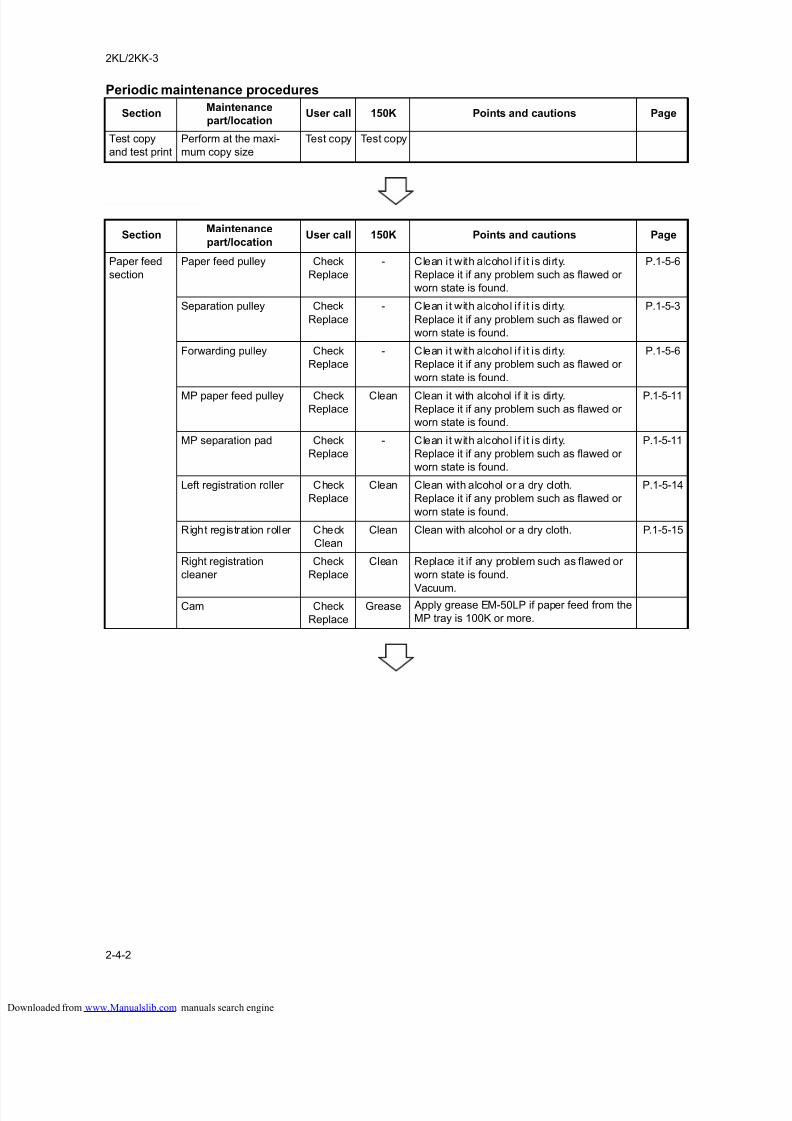
8/18/2019 taskalfa_220
http://slidepdf.com/reader/full/taskalfa220 244/300
2KL/2KK-3
2-4-2
Periodic maintenance procedures
SectionMaintenance
part/locationUser call 150K Points and cautions Page
Test copy
and test print
Perform at the maxi-
mum copy size
Test copy Test copy
SectionMaintenance
part/locationUser call 150K Points and cautions Page
Paper feed
section
Paper feed pulley Check
Replace
- Clean it with alcohol if i t is dirty.
Replace it if any problem such as flawed or
worn state is found.
P.1-5-6
Separation pulley Check
Replace
- Clean it with alcohol if i t is dirty.
Replace it if any problem such as flawed or
worn state is found.
P.1-5-3
Forwarding pulley Check
Replace
- Clean it with alcohol if i t is dirty.
Replace it if any problem such as flawed or
worn state is found.
P.1-5-6
MP paper feed pulley CheckReplace
Clean Clean it with alcohol if it is dirty.Replace it if any problem such as flawed or
worn state is found.
P.1-5-11
MP separation pad Check
Replace
- Clean it with alcohol if i t is dirty.
Replace it if any problem such as flawed or
worn state is found.
P.1-5-11
Left registration roller Check
Replace
Clean Clean with alcohol or a dry cloth.
Replace it if any problem such as flawed or
worn state is found.
P.1-5-14
Right registration roller Check
Clean
Clean Clean with alcohol or a dry cloth. P.1-5-15
Right registration
cleaner
Check
Replace
Clean Replace it if any problem such as flawed or
worn state is found.
Vacuum.Cam Check
Replace
Grease Apply grease EM-50LP if paper feed from the
MP tray is 100K or more.
loaded from www.Manualslib.com manuals search engine
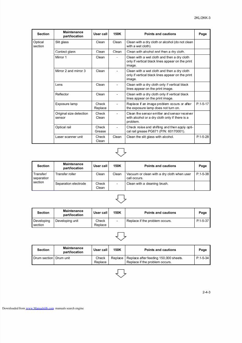
8/18/2019 taskalfa_220
http://slidepdf.com/reader/full/taskalfa220 245/300
2KL/2KK-3
2-4-3
SectionMaintenance
part/locationUser call 150K Points and cautions Page
Optical
section
Slit glass Clean Clean Clean with a dry cloth or alcohol (do not clean
with a wet cloth).
Contact glass Clean Clean Clean with alcohol and then a dry cloth.
Mirror 1 Clean - Clean with a wet cloth and then a dry cloth
only if vertical black lines appear on the print
image.
Mirror 2 and mirror 3 Clean - Clean with a wet cloth and then a dry cloth
only if vertical black lines appear on the print
image.
Lens Clean - Clean with a dry cloth only if vertical black
lines appear on the print image.
Reflector Clean - Clean with a dry cloth only if vertical black
lines appear on the print image.
Exposure lamp Check
Replace
- Replace if an image problem occurs or after
the exposure lamp does not turn on.
P.1-5-17
Original size detection
sensor
Check
Clean
- Clean the sensor emitter and sensor receiver
with alcohol or a dry cloth only if there is a
problem.
Optical rail Check
Grease
- Check noise and shifting and then apply opti-
cal rail grease PG671 (P/N: 60170001).
Laser scanner unit Check
Clean
Clean Clean the slit glass with alcohol. P.1-5-28
SectionMaintenance
part/locationUser call 150K Points and cautions Page
Transfer/
separation
section
Transfer roller Clean Clean Vacuum or clean with a dry cloth when user
call occurs.
P.1-5-38
Separation electrode Check
Clean
- Clean with a cleaning brush.
SectionMaintenance
part/locationUser call 150K Points and cautions Page
Developing
section
Developing unit Check
Replace
- Replace if the problem occurs. P.1-5-37
SectionMaintenance
part/locationUser call 150K Points and cautions Page
Drum section Drum unit Check
Replace
Replace Replace after feeding 150,000 sheets.
Replace if the problem occurs.
P.1-5-34
loaded from www.Manualslib.com manuals search engine
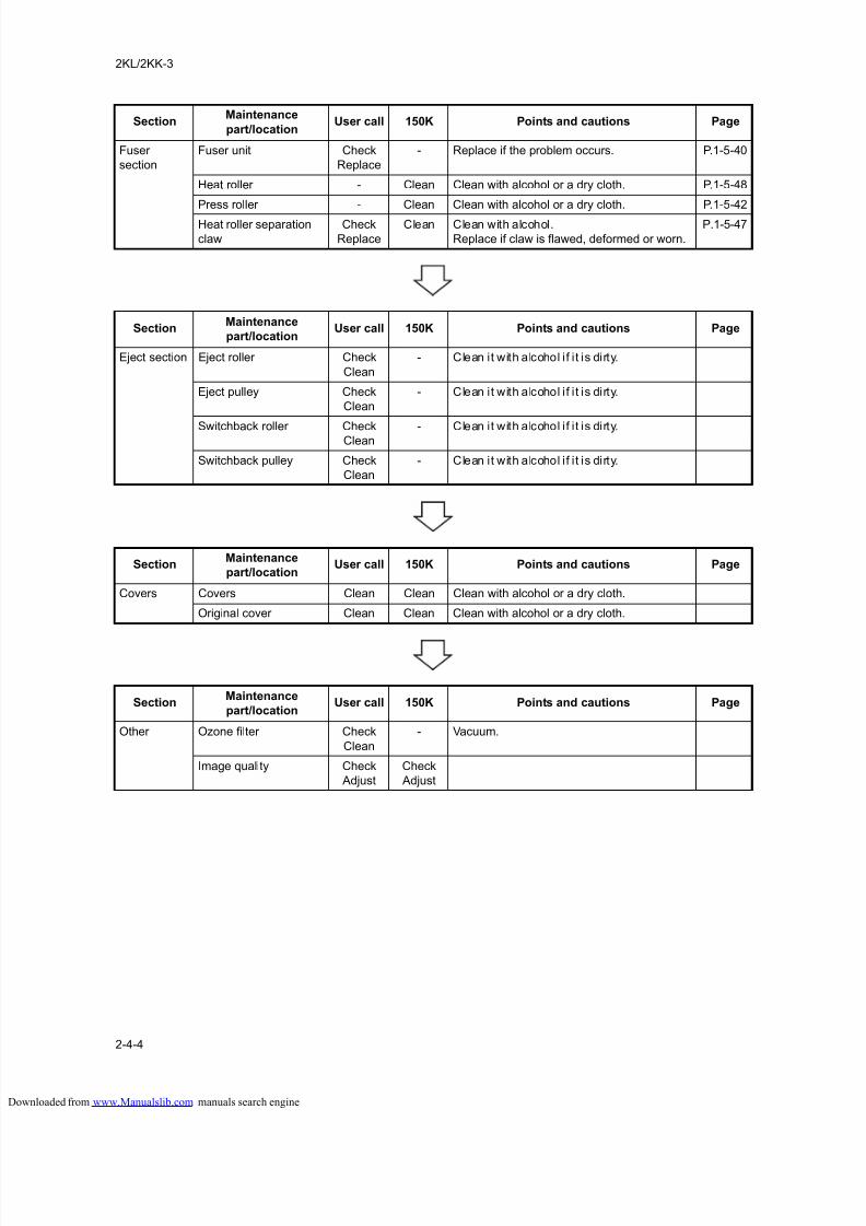
8/18/2019 taskalfa_220
http://slidepdf.com/reader/full/taskalfa220 246/300
2KL/2KK-3
2-4-4
SectionMaintenance
part/locationUser call 150K Points and cautions Page
Fuser
section
Fuser unit Check
Replace
- Replace if the problem occurs. P.1-5-40
Heat roller - Clean Clean with alcohol or a dry cloth. P.1-5-48
Press roller - Clean Clean with alcohol or a dry cloth. P.1-5-42
Heat roller separation
claw
Check
Replace
Clean Clean with alcohol.
Replace if claw is flawed, deformed or worn.
P.1-5-47
SectionMaintenance
part/locationUser call 150K Points and cautions Page
Eject section Eject roller Check
Clean
- Clean it with alcohol if i t is dirty.
Eject pulley Check
Clean
- Clean it with alcohol if i t is dirty.
Switchback roller CheckClean
- Clean it with alcohol if i t is dirty.
Switchback pulley Check
Clean
- Clean it with alcohol if i t is dirty.
SectionMaintenance
part/locationUser call 150K Points and cautions Page
Covers Covers Clean Clean Clean with alcohol or a dry cloth.
Original cover Clean Clean Clean with alcohol or a dry cloth.
SectionMaintenance
part/locationUser call 150K Points and cautions Page
Other Ozone filter Check
Clean
- Vacuum.
Image quality Check
Adjust
Check
Adjust
loaded from www.Manualslib.com manuals search engine
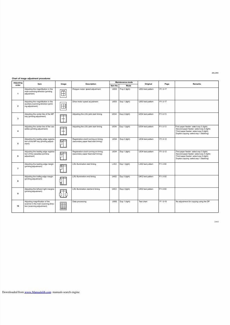
8/18/2019 taskalfa_220
http://slidepdf.com/reader/full/taskalfa220 247/300
2KL/
2
Chart of image adjustment procedures
Adjusting
order Item Image Description
Maintenance modeOriginal Page Remarks
Item No. Mode
1
Adjusting the magnification in the
main scanning direction (printing
adjustment)
Polygon motor speed adjustment U053 Exp.2 (light) U053 test pattern P.1-3-17
2
Adjusting the magnification in the
auxiliary scanning direction (print-
ing adjustment)
Drive motor speed adjustment U053 Exp.1 (light) U053 test pattern P.1-3-17
3
Adjusting the center line of the MPtray (printing adjustment)
Adjusting the LSU print start timing U034 Exp.2 (light) U034 test pattern P.1-3-13
4
Adjusting the center line of the cas-
settes (printing adjustment)
Adjusting the LSU print start timing U034 Exp.1 (light) U034 test pattern P.1-3-13 First paper feeder: select exp.3 (light)
Second paper feeder: select exp.4 (light)
Third paper feeder: select exp.5 (light)
Duplex copying: select exp.1 (flashing)
5
Adjusting the leading edge registra-
tion of the MP tray (printing adjust-
ment)
Registration clutch turning on timing
(secondary paper feed start timing)
U034 Exp.2 (light) U034 test pattern P.1-3-12
6
Adjusting the leading edge registra-
tion of the cassettes (printing
adjustment)
Registration clutch turning on timing
(secondary paper feed start timing)
U034 Exp.1 (light) U034 test pattern P.1-3-12 First paper feeder: select exp.3 (light)
Second paper feeder: select exp.4 (light)
Third paper feeder: select exp.5 (light)
Duplex copying: select exp.1 (flashing)
7
Adjusting the leading edge margin
(printing adjustment)
LSU illumination start timing U402 Exp.1 (light) U402 test pattern P.1-3-50
8
Adjusting the trailing edge margin
(printing adjustment)
LSU illumination end timing U402 Exp.3 (light) U402 test pattern P.1-3-50
9
Adjusting the left and right margins
(printing adjustment)
LSU illumination start/end timing U402 Exp.2 (light) U402 test pattern P.1-3-50
10
Adjusting magnification of the
scanner in the main scanning direc-
tion (scanning adjustment)
Data processing U065 Exp.1 (light) Test chart P.1-3-19 No adjustment for copying using the DP.
loaded from www.Manualslib.com manuals search engine
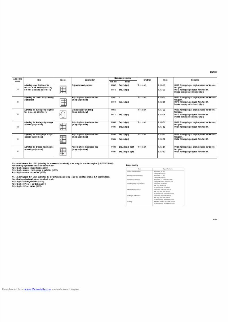
8/18/2019 taskalfa_220
http://slidepdf.com/reader/full/taskalfa220 248/300
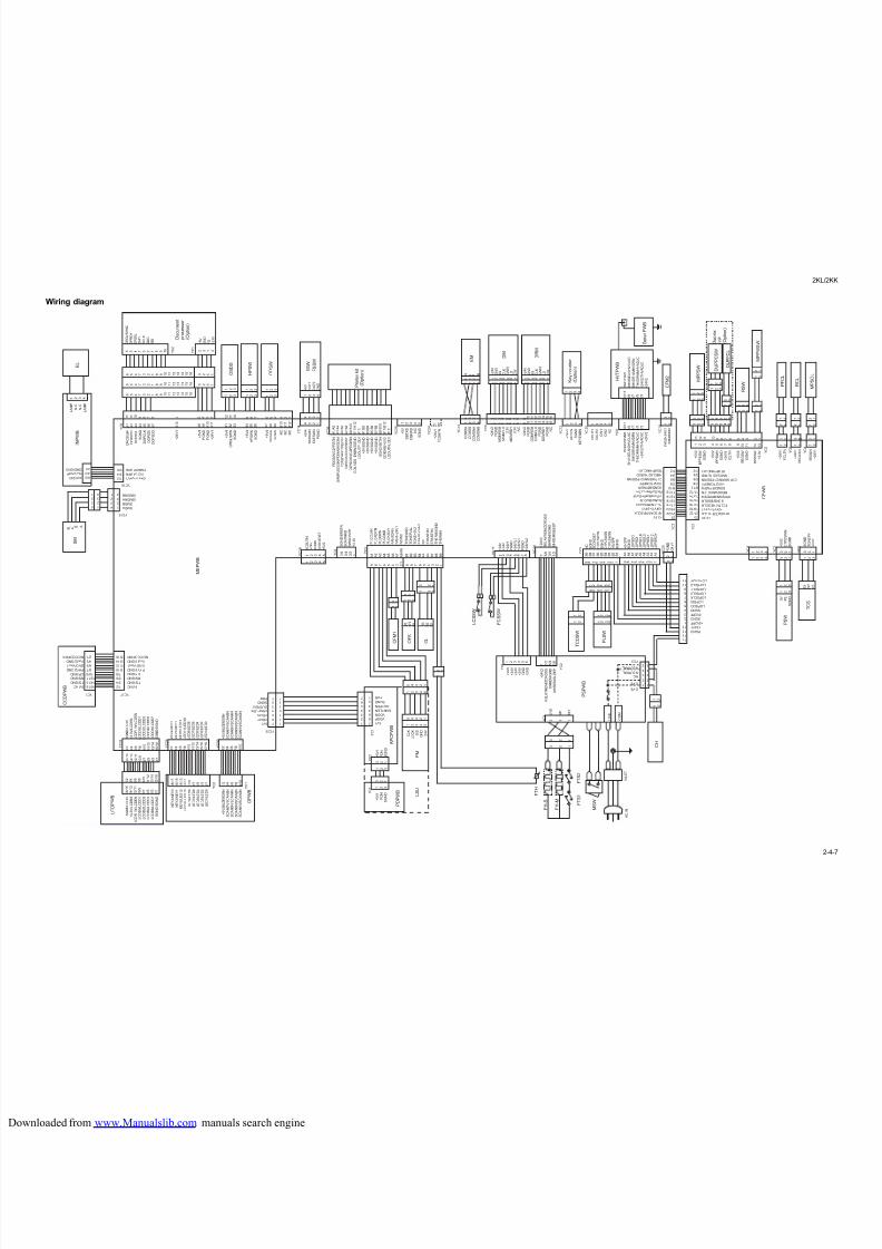
8/18/2019 taskalfa_220
http://slidepdf.com/reader/full/taskalfa220 249/300
2KL/
2
Wiring diagram
I S M D A
I S M D B
I S M D N A
I S M D N B
4 3 2 1
2 1
1
L A M P
N . C .
N . C .
L A M P
1 2 3
Y C 5
S G N D / E R S T N
S C K / W R S I
W R S O / V P P
+ 3
. 3 V
Y C 1 4
Y C 1 5
Y C 1 6
Y C 2
P D G D I N / C 2 P R S T N
S A M P L E G D I N / P D M A S K G D I N
C 2 P S D I R / C 2 P E G S I
C 2 P E G S O / C 2 P S B S Y
C 2 P S C K N / C 2 P E G I R N
G D I L V D S
_ E N B N / S G N D
L D O U T P
_ G D I
+ 5 V / S G N D
+ 5 V / S G N D
+ 5 V / S G N D
+ 5 V / S G N D
S G N D / S E T N
G D I E N B / + 5 V 3
L D O U T N
_ G D I
Y C 3 6
+ 5 V
D B T X D
D B R X D
N C
S G N D
Y C 2 6
Y C 2 4
+
2 4 V 1
T C O
N T N
1 2 3
1 2 3 4
Y C 3 5
1 2 3
1 2 3
1 2 3 1 2 3
9 8 7 6 5 4 3 2 / 1
9 8 7 6 5 4 3 2 1
O R G T
I M N
D O P R D Y
D O P
S E L
S G N D
D O P
C L K
D O P
S D I
D O P S D O
3 2 4 1 6 5 4 7 3 2 1 8 9 1 0
1 1
1 2
1 3
1 4
1 5
1 6
3 2 4 1 6 5 4 7 3 2 1 8 9 1 0
1 1
1 2
1 3
1 4
1 5
1 6
6 5 4 7 3 2 1 8 9 1 0
1 1
1 2
1 3
1 4
1 5
1 6
2 3 1 4 6 5 4 7 3 2 1 8 9 1 0
A 8
A 9
A 1 0
A 1 1
1 2
1 1
1 0
9 8 7 6 5 4 3 2
+ 2
4 V 1
1
4
3
2
1
4
3
2
1
1
2
3
4
1 2 3 4
1 / 2
3 / 4
5 / 6
7 / 8
9 / 1 0
1 1 / 1 2
1 3 / 1 4
1 5 / 1 6
1 6 / 1 5
1 4 / 1 3
1 2 / 1 1
1 0 / 9
8 / 7
6 / 5
4 / 3
2 / 1
5 V / N C
T G / G N D
R S / G N D
C P / G N D
P H Y 2 / G N D
G N D / V o u t 1
V o u t 2 / G N D
N C / C C D P W R
Y C 2 7 Y C 1
Y C 3
A 1
A 2
A 3
A 4
A 5
A 6
A 7
A 8 / A 9
P L G C L K N
P L G R D Y N
P L G D R N
P L G G N D
P L G + 2 4 V 1
F A N 1 D R N
F A N 1 + 2 4 V 1
N C / N C
B 1
B 2
B 3
B 4
B 5
B 6
B 7
B 8
B 9
T O N E G N D
T O N E F U L L
T O N E + 5 V 2
E R A S E + 2 4 V 1
N C
E R A S E 2 N
E R A S E 1 N
T H E R M A G N D
T H E R M A
B 3
W 2
R 1
1 2 3
1 2 3
2 1
3 2 1
3 2 1
1 2
A C S U T N
+ 2 4 V
S G N D
T C R O T D E T
+ 5 V 2
Y C 1 9
1 2 3 4 5
1
2
3
4
1 / 2
3 / 4
5 / 6
A 1
A 2
A 3
A 4
A 5
A 6
A 7
A 1 2
+
5 V 4
P G N D
P G N D
+ 2
4 V 1
B 1
B 2
B 3
+
5 V 4
O R G L S
W N
S G N D
1 2
1 1
1 0
B 4
B 5
B 6
+
5 V 4
H P S
W N
S G N D
9 8 7
B 7
B 8
B 9
+
5 V 4
O P S
W N
S G N D
3 2 1
B 1 0
B 1 1
B 1 2
N C
N C
N C
6 5 4
+ 5 V 4
S E P S W N
E X T S W N
P G N D
7 / 6
5 / 4
3 / 2
1
A 1 / A 2
A 3 / A 4
A 5 / A 6
A 7 / A 8
A 9 / A 1 0
A 1 1 / A 1 2
A 1 3
B 1 / B 2
B 3 / B 4
B 5 / B 6
B 7 / B 8
B 9 / B 1 0
B 1 1 / B 1 2
B 1 3
5 V 1
V D O P
V D O N
S A M P L E N
O U T P E N
S G N D
P D N
7
6
5
4
3
2
1
1 2 3 4 5 1 2
1
2
3
4
5
6
7
5 4 3 2 1
1 2 3 4 5
Y C 1
Y C 2
Y C 1
3 2 1
5 4 3 2 1
1 2 3 4 5
7
6
5
4
3
2
1
+ 5 V 1
P D N
S G N D
1 2 3
3 2 1
1 2 3
1
2
3
4
5
6
7
5 V / N C
T G / G N D
R S / G N D
C P / G N D
P H Y 2 / G N D
G N D / V o u t 1
V o u t 2 / G N D
N C / C C D P W R
+ 2 4 V 1 / + 2 4 V 1
N C / L A M P N
P G N D / P G N D
2 4 V / 2 4 V
N C / L A M P
G N D / G N D
5 V 1
V D O P
V D O N
S A M P L E N
O U T P E N
S G N D
P D N
Y C 3 1
Y C 2 9
Y C 3 0
1 / 2
3 / 4
5 / 6
7 / 8
9 / 1 0
1 / 2
3 / 4
5 / 6
7 / 8
9 / 1 0
1 1 / 1 2
1 3 / 1 4
1 5 / 1 6
1 7 / 1 8
1 6 / 1 5
1 4 / 1 3
1 2 / 1 1
1 0 / 9
8 / 7
6 / 5
4 / 3
2 / 1
1 / 2
3 / 4
5 / 6
7 / 8
9 / 1 0
1 1 / 1 2
1 3 / 1 4
1 5 / 1 6
S G N D / + 3
. 3 V
+ 3
. 3 V / L C D R S
L C D R
_ W / L C D E N
L C D D 0 / L C D D 1
L C D D 2 / L C D D 3
L C D D 4 / L C D D 5
L C D D 6 / L C D D 7
S G N D / S G N D
+ 5 V / B U Z E R D R N
S C A N 7 N / S C A N 6 N
S C A N 5 N / S C A N 4 N
S C A N 3 N / S C A N 2 N
S C A N 1 N / S C A N 0 N
K E Y 4 / K E Y 3
K E Y 2 / K E Y 1
K E Y 0 / L E D 1 2
L E D 1 1 / L E D 1 0
L E D 9 / L E D 8
L E D 7 / L E D 6
L E D 5 / L E D 4
L E D 3 / L E D 2
L E D 1 / L E D 0
1 / 2
3 / 4
5 / 6
7 / 8
9 / 1 0
1 1 / 1 2
1 3 / 1 4
1 5 / 1 6
1 6 / 1 5
1 4 / 1 3
1 2 / 1 1
1 0 / 9
8 / 7
6 / 5
4 / 3
2 / 1
1 / 2
3 / 4
5 / 6
7 / 8
9 / 1 0
1 8 / 1 7
1 6 / 1 5
1 4 / 1 3
1 2 / 1 1
1 0 / 9
8 / 7
6 / 5
4 / 3
2 / 1
6 / 5
4 / 3
2 / 1
R 3
B 2
G 1
+ 5 V
O U T 1
O U T 2
G N D
1 2 3 4 5
+ 5 V / B U Z E R D R N
S C A N 7 N / S C A N 6 N
S C A N 5 N / S C A N 4 N
S C A N 3 N / S C A N 2 N
S C A N 1 N / S C A N 0 N
Y C 1
Y C 2
K E Y 4 / K E Y 3
K E Y 2 / K E Y 1
K E Y 0 / L E D 1 2
L E D 1 1 / L E D 1 0
L E D 9 / L E D 8
L E D 7 / L E D 6
L E D 5 / L E D 4
L E D 3 / L E D 2
L E D 1 / L E D 0
S G N D / + 3
. 3 V
+ 3
. 3 V / L C D R S
L C D R
_ W / L C D E N
L C D D 0 / L C D D 1
L C D D 2 / L C D D 3
L C D D 4 / L C D D 5
L C D D 6 / L C D D 7
S G N D / S G N D
B_ A
_ B A
+ 5 V 1
P D N
S G N D
C L K
L O C K
S / S
G N D
2 4 V
4 3 2 1
O R G V S Y N C
D P R D Y
D P S E L
G N D
S C L K
S D O
S D I
+ 5 V
G N D
F G
+ 2 4 V
Y C 1
Y C 2
1 2 3
A C I N
L I V E
3 2 1
3 2 1
Y C 1 2
1 0 / 1 1
8 / 9
6 / 7
4 / 5
2 / 3
1
1 0 / 1 1
8 / 9
6 / 7
4 / 5
2 / 3
1
B 9
B 8
B 7
B 6
B 5
B 4
B 3
B 2
B 1
1 2 3 4
1 2 3 4 5 6 7 8 9 1 0
1 1
1 2
1 3
1 3 1 2 1 1 1 0 9 8 7 6 5 4 3 2 1
1 2 3
1 2 3 4 5
1 2
+ 5 V 2
C 1 P D S W N
S G N D
1 2 3
1 2 3
3 2 1
3 2 1
B 3
W 2
R 1
1 2 3
1 2
1 2
1 2
3 2 1
1 2 3
Y C 8
Y C 1 3
Y C 6
Y C 1 7
7 5 / 6
3 / 4
1 / 2 Y
C 1 8
F A N 2 +
2 4 V 1
F A N 2 D R N
Y C 1 0
1 2 3 4
Y C 2 5
Y C 9
Y C 7
P G N D / P G N D
S H V I S E L N / D H V C L
K C
S H V D R N / M H V D R N
T H V D R N / M H V A D
J C
+ 2 4 V 2 / T H V A D
J C
+ 2 4
V 2
2 3
2 1 / 2 2
1 9 / 2 0
1 7 / 1 8
1 5 / 1 6
1 3 / 1 4
1 1 / 1 2
9 / 1 0
7 / 8
5 / 6
3 / 4
1 / 2
1 3 / 2
5 / 4
7 / 6
Y C 2
2 3
2 1 / 2 2
1 9 / 2 0
1 7 / 1 8
1 5 / 1 6
1 3 / 1 4
1 1 / 1 2
9 / 1 0
7 / 8
5 / 6
3 / 4
1 / 2
Y C 1
1 2 3 4 5 6
1 2 3
1 2 3
1 2
2 1
1 2 3 4
I N L E T
5 4 3 2 1
9 8 7 6 5 4 3 2 1 9 8 7 6 5 4 3 2 1
1 2 3
1 2 3
3 2 1
Y C 4
+ 2 4 V 1
F C L T N
+ 2 4 V 1
R E G C L N
1 2
1
2
3
4
5
1 2
2 1
1 2
C O M
2 1
+ 3 . 3 V
R F S D A T / R F S C L K
+ 2 4 V 1 / + 2 4 V 1
F C L T N / R E G C L N
S G N D / B S O L N
I P P S W N / B P P E S W
R E G S W N / I C L T N
S G N D / B P W S W
+ 5 V 2 / T O N E P Y
C 1 P W S W N / C 1 P D S W N
H M C L K 2 / H U M I D
T E M P / H M C L K 1
S G N D
N C
S G N D
T C O N D E T
C 1 P L S W 1 N
S G N D
C 1 P L S W 2 N
C 1 P L S W 3 N
+ 5 V 2 P F
P G N D
+ 2 4 V 1
1 6
1 5
1 3
1 2
1
2
3
4
5
6
7
8
9
1 0
1 1
+ 2 4 V 2
R E L A Y R E M / Z C R O S S
S H R E M / S G N D
M H R E M / S L E E P
+ 2 4 V
+ 2 4 V
+ 2 4 V 1
P G N D
+ 2 4 V I L 1
+ 2 4 V I L 1
P G N D
+ 2 4 V I L 2
1 2 3 4 5 6 7 8
+
2 4 V 1
K E
Y C N
S
G N D
K E Y E
N B N
1 2 3 4
+ 5 V 2
B P P E S W
S G N D
+ 5 V 2
I P P S W N
S G N D
+ 2 4 V 1
I C L T N
+ 5 V 2
R E G S W
S G N D
B P W S W
+ 3
. 3 V
Y C 4
Y C 2
Y C 3
Y C 3
3 2 1
S G N D
T O N E P Y
+ 5 V 2
1 2
B S O L N
+ 2 4 V 1
Y C 5
Y C 1
Y C 6
1 2
Y C 8
L I V E
S H
M H
G N D
+ 2 4 V
+ 2 4 V
+ 2 4 V
G N D
G N D
+ 2 4 V 2
R E L A Y R E M / Z C R O S S
S H R E M / G N D
M H R E M / S L E E P
L I V E
N C
N E U T R A L
N E U T R A L
L I V E
A 9
A 8
A 7
A 6
A 5
A 4
A 3
A 2
A 1
+ 5 V 2 P F
S G N D
L O P S D O
L O P S D I
L O P S C L K
L O P S E L 0
L O P S E L 1
L O P S E L 2
L O P S R D Y
1 2
2 1
2 1
1 2
2 1
1 2
C O
U T 1
C O
U T 2
C I N 1
C I N 2
N C
1 2 3 4 5
Y C 2 0
2 1
+ 3 . 3 V
R F S D A T / R F S C L K
+ 2 4 V 1 / + 2 4 V 1
F C L T N / R E G C L N
S G N D / B S O L N
I P P S W N / B P P E S W
R E G S W N / I C L T N
S G N D / B P W S W
+ 5 V 2 / T O N E P Y
C 1 P W S W N / C 1 P D S W N
H M C L K 2 / H U M I D
T E M P / H M C L K 1
G N D / G N D
S H V I S E L N / H V C L K C
S H V D R N / M H V D R N
T H V D R N / M H V A D J C
+ 2 4 V 2 / T H V A D J C
+ 2 4 V 2
P G N D
+ 2 4 V 1
+ 5 V 2 P F
S G N D
5 V 2 P F
S G N D
L O P S D O
L O P S D I
L O P S C L K
L O P S E L 0
L O P S E L 1
L O P S E L 2
L O P S R D Y
1 2 3 4 5 6
6 5 4 3 2 1
1 2 3 4 5 6 7 8 9 1 0
1 1
1 2
1 3
1 4
1 5
1 6
C
O M D A
C
O M D B
C O
M D N A
C O
M D N B
1 2 3 4
4 3 2 1
4 3 2 1 1 2 3 4
- A A B - B
+ 2 4 V 2
P G N D
M D M R E M
M D
M C L K
3 . 3
V
M D
M R D Y
3 . 3
V N C
+ 2 4 V 2
P G N D
D D M R E M
D D
M C L K
P G N D
D D
M R D Y
P G N D
N C
+ 2 4 V
G N D
S S
C L K
G A I N
L D
C W
+ 2 4 V
G N D
S S
C L K
G A I N
L D
C W
1 2 3 4 5 6 7 1 2 3 4 5 6 7
1 2 3 4 5 6 7 1 2 3 4 5 6 7
2 1
5 V
P E
S G N D
2 1 1 2 1 2 1 2
1 2 3 4 2 1
1 2 3 4 5 6 7 8 9 1 0
1 1
1 2
1 3
1 4
1 5
1 6
1
2
3
4
5
1 2 3 4 1 2
M E P W B
E L
I N P W
B
S M
O S D S
D o c u m e n
t
p r o c e s s o r
( O p
t i o n
)
H P S W
O D S W
E S W
F S S W
P r i n
t e r
k i t
( O p
t i o n
)
C C D P W B
C F M 1
O F S
C L
P M
L S U
P D P W B
A P C P W B
O P W B
L C D P W B
M S W F
T S 1
F H - M
F H - S
F T H
F T S 2
C H
P S P W B
F C S S W
T C D S W
P L S W
L C S S W
K e y c o u n
t e r
( O p
t i o n
)
C F M 2
M P P S W
D U P P C S W
D U P F C L
R S W
M P P W S W
P F C L
R C L
M P S O L
D u p
l e x
u n
i t
( O p
t i o n
)
P S W
T C S
C P W B
E M D
M D R M
Z e n e r
P W B
H V T P W B
loaded from www.Manualslib.com manuals search engine

8/18/2019 taskalfa_220
http://slidepdf.com/reader/full/taskalfa220 250/300
INSTALLATION GUIDE
INSTALLATION GUIDE FOR
DOCUMENT PROCESSOR
Output Connector for Interconnecting Cable is non-LPS.
Output: 114.5 VA max.
Please use the item below Interconnecting Cable/
P/N: 303MX46010
loaded from www.Manualslib.com manuals search engine
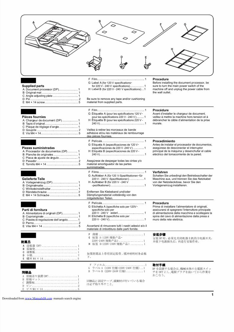
8/18/2019 taskalfa_220
http://slidepdf.com/reader/full/taskalfa220 251/3001
A B
C
D E
F G
H
Supplied partsA Document processor (DP)....................... 1B Original mat ............................................. 1C Angle adjusting plate ............................... 1D Pin ...........................................................2E M4 × 14 screw......................................... 5
English F Film.......................................................... 1G Label A (for 120 V specifications・
for 220 V - 240 V specifications)................. 1H Label B (for 220 V - 240 V specifications)...1
Be sure to remove any tape and/or cushioningmaterial from supplied parts.
ProcedureBefore installing the document processor, besure to turn the main power switch of themachine off and unplug the power cable fromthe wall outlet.
Pièces fourniesA Chargeur de document (DP) ...................1B Tapis d’original......................................... 1C Plaque de réglage d’angle....................... 1D Goupille ................................................... 2E Vis M4 × 14.............................................. 5
FrançaisF Film.......................................................... 1G Étiquette A (pour les spécifications 120 V・
pour les spécifications 220 V - 240 V)......... 1H Étiquette B (pour les spécifications 220 V -
240 V).......................................................1
Veillez à retirer les morceaux de bandeadhésive et/ou les matériaux de rembourragedes pièces fournies.
ProcédureAvant d’installer le chargeur de document,
veillez à mettre la machine hors tension et àdébrancher le câble d’alimentation de la prisemurale.
Piezas suministradasA Procesador de documentos (DP) ............ 1B Plancha de originales ..............................1C Placa de ajuste de ángulo ....................... 1D Pasador ...................................................2E Tornillo M4 × 14 ....................................... 5
EspañolF Película.................................................... 1G Etiqueta A (especificaciones de 120 V・
especificaciones de 220 V -240 V) ............. 1H Etiqueta B (especificaciones de 220 V -
240 V).......................................................1
Asegúrese de despegar todas las cintas y/omaterial amortiguador de las partessuministradas.
ProcedimientoAntes de instalar el procesador de documentos,asegúrese de desconectar el interruptorprincipal de la máquina y desenchufar el cableeléctrico del tomacorriente de la pared.
Gelieferte TeileA Vorlageneinzug (DP) ............................... 1B Originalmatte ........................................... 1C Winkeleinstellhalter.................................. 1D Rändelschraube ...................................... 2E M4 × 14 Schraube ................................... 5
Deutsch
F Films ........................................................1
G Aufkleber A (für 120 V-Spezifikationen・für220 V - 240 V -Spezifikationen) ..................1
H Aufkleber B (für 220 V - 240 V-pezifikationen)..........................................1
Entfernen Sie Klebeband und/oderDämpfungsmaterial vollständig von denmitgelieferten Teilen.
VerfahrenSchalten Sie unbedingt den Betriebsschalter derMaschine aus, und trennen Sie das Netzkabelvon der Netzsteckdose, bevor Sie denVorlageneinzug installieren.
Parti di fornituraA Alimentatore di originali (DP)................... 1B Coprioriginale .......................................... 1C Piastra di regolazione dell’angolo............ 1D Perno.......................................................2E Vite M4 × 14 ............................................ 5
Italiano F Película.................................................... 1G Etichetta A (specifiche solo per 120V・
specifiche solo per220 V - 240 V esteri................................ 1
H Etichetta B (specifiche solo per220 V - 240 V)...........................................1
Accertarsi di rimuovere tutti i nastri adesivi e/o ilmateriale di imbottitura dalle parti fornite.
ProceduraPrima di installare l’alimentatore di originali,assicurarsi di spegnere l’interruttore principaledi alimentazione della macchina e scollegare laspina del cavo di alimentazione dalla presa amuro della rete elettrica.
同梱品同梱品同梱品同梱品A 原稿送り装置(DP)....................1B 原稿マット..........................1C 調整板..............................1D ピン................................2E ビスM4× 14 ........................5
日本語日本語日本語日本語 F フィルム............................1G ラベル A(120V 仕様・220V-240V 仕様)..1H ラベル B(220V-240V 仕様)............1
同梱品に固定テープ、緩衝材が付いている場合は必ず取り外すこと。
取付手順取付手順取付手順取付手順DP を設置する場合は、機械本体の主電源スイッチを OFF にし、電源プラグを抜いてから作業をおこなう。
附属品附属品附属品附属品A 送稿器 (DP) .........................1B 原稿垫..............................1C 调整板..............................1D 卡销................................2E 螺丝 M4× 14 ........................5
简体中文简体中文简体中文简体中文 F 薄膜 ...............................1G 标签 A(120V 规格产品・
220V-240V规格产品1 .................1H 标签 B(220V-240V规格产品).........1
如果附属品上带有固定胶带、缓冲材料时务必揭下。
安装步骤安装步骤安装步骤安装步骤安装 DP时,必须先关闭机器主机的主电源开关,并拔下电源插头后,再进行安装作业。
loaded from www.Manualslib.com manuals search engine
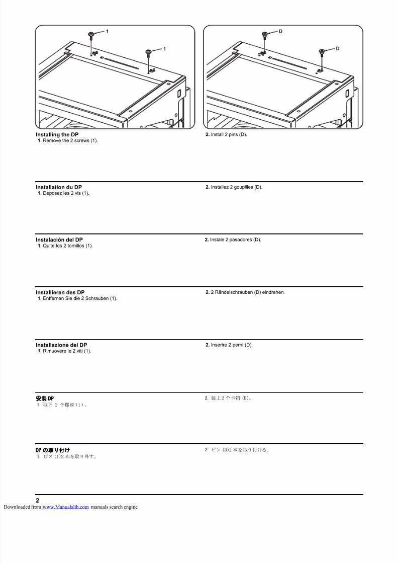
8/18/2019 taskalfa_220
http://slidepdf.com/reader/full/taskalfa220 252/3002
1
1
D
D
Installing the DP1. Remove the 2 screws (1).
2. Install 2 pins (D).
Installation du DP1. Déposez les 2 vis (1).
2. Installez 2 goupilles (D).
Instalación del DP1. Quite los 2 tornillos (1).
2. Instale 2 pasadores (D).
Installieren des DP1. Entfernen Sie die 2 Schrauben (1).
2. 2 Rändelschrauben (D) eindrehen.
Installazione del DP1. Rimuovere le 2 viti (1).
2. Inserire 2 perni (D).
DPDPDPDP のののの取取取取りりりり付付付付けけけけ1. ビス(1)2 本を取り外す。
2. ピン(D)2 本を取り付ける。
安装安装安装安装 DPDPDPDP1. 取下 2 个螺丝(1)。
2. 装上2 个卡销 (D)。
loaded from www.Manualslib.com manuals search engine
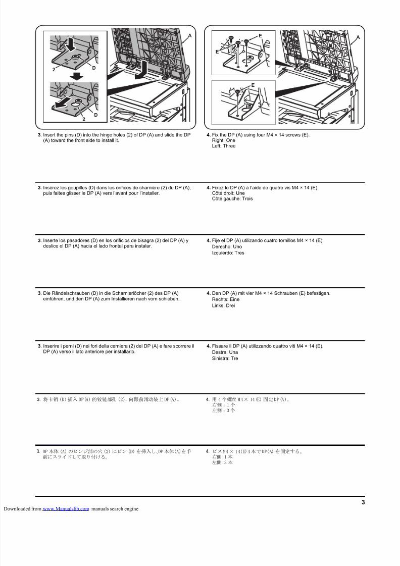
8/18/2019 taskalfa_220
http://slidepdf.com/reader/full/taskalfa220 253/3003
E A
E
E
D
A
D
2
2
3. Insert the pins (D) into the hinge holes (2) of DP (A) and slide the DP(A) toward the front side to install it.
4. Fix the DP (A) using four M4 × 14 screws (E).Right: OneLeft: Three
3. Insérez les goupilles (D) dans les orifices de charnière (2) du DP (A),puis faites glisser le DP (A) vers l’avant pour l’installer.
4. Fixez le DP (A) à l’aide de quatre vis M4 × 14 (E).Côté droit: Une
Côté gauche: Trois
3. Inserte los pasadores (D) en los orificios de bisagra (2) del DP (A) ydeslice el DP (A) hacia el lado frontal para instalar.
4. Fije el DP (A) utilizando cuatro tornillos M4 × 14 (E).Derecho: UnoIzquierdo: Tres
3. Die Rändelschrauben (D) in die Scharnierlöcher (2) des DP (A)
einführen, und den DP (A) zum Installieren nach vorn schieben.
4. Den DP (A) mit vier M4 × 14 Schrauben (E) befestigen.
Rechts: EineLinks: Drei
3. Inserire i perni (D) nei fori della cerniera (2) del DP (A) e fare scorrere ilDP (A) verso il lato anteriore per installarlo.
4. Fissare il DP (A) utilizzando quattro viti M4 × 14 (E).Destra: UnaSinistra: Tre
3. 将卡销(D)插入 DP(A)的铰链部孔 (2),向跟前滑动装上DP(A)。 4. 用 4个螺丝 M4× 14(E) 固定DP(A)。右侧 :1 个左侧 :3 个
3. DP 本体 (A) のヒンジ部の穴(2) にピン (D) を挿入し、DP本体(A)を手前にスライドして取り付ける。
4. ビスM4× 14(E)4本でDP(A) を固定する。右側:1本左側:3本
loaded from www.Manualslib.com manuals search engine
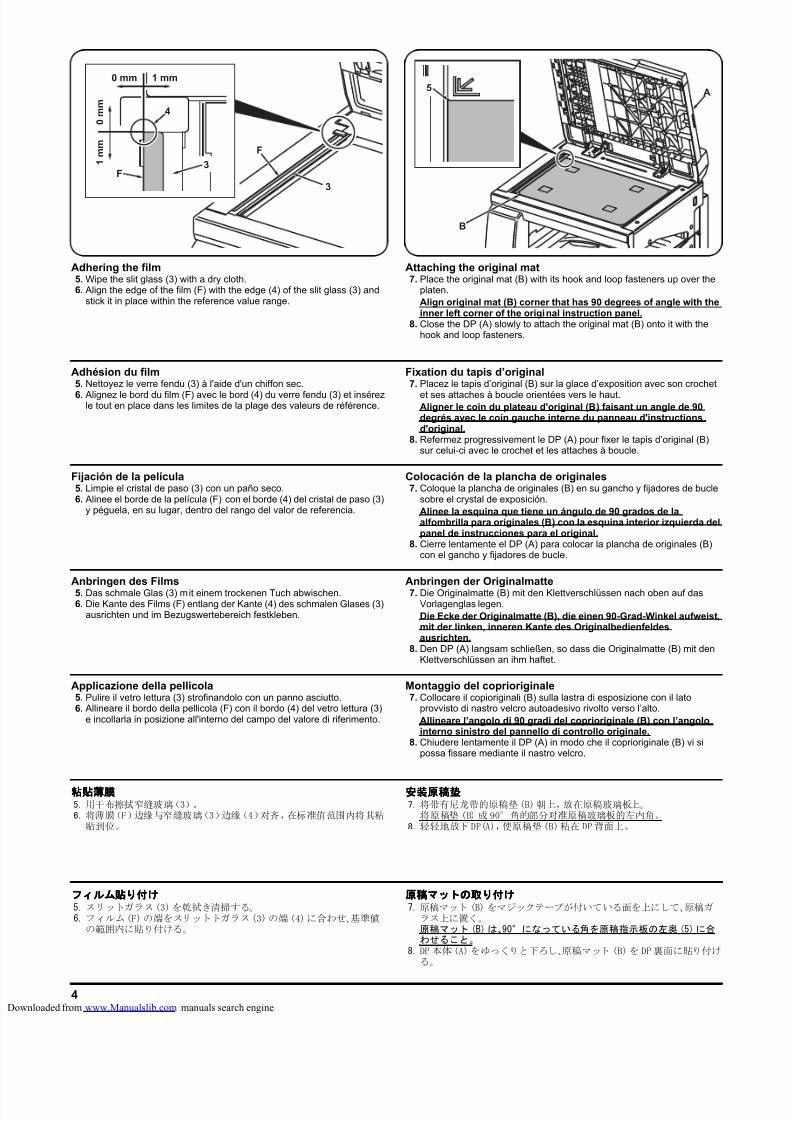
8/18/2019 taskalfa_220
http://slidepdf.com/reader/full/taskalfa220 254/3004
B
A5
F
4
1 mm0 mm
0 m m
1 m m
3
3
F
Adhering the film5. Wipe the slit glass (3) with a dry cloth.6. Align the edge of the film (F) with the edge (4) of the slit glass (3) and
stick it in place within the reference value range.
Attaching the original mat7. Place the original mat (B) with its hook and loop fasteners up over the
platen.Align original mat (B) corner that has 90 degrees of angle with theinner left corner of the original instruction panel.
8. Close the DP (A) slowly to attach the original mat (B) onto it with thehook and loop fasteners.
Adhésion du film5. Nettoyez le verre fendu (3) à l'aide d'un chiffon sec.
6. Alignez le bord du film (F) avec le bord (4) du verre fendu (3) et insérezle tout en place dans les limites de la plage des valeurs de référence.
Fixation du tapis d’original7. Placez le tapis d’original (B) sur la glace d’exposition avec son crochet
et ses attaches à boucle orientées vers le haut.Aligner le coin du plateau d'original (B) faisant un angle de 90degrés avec le coin gauche interne du panneau d'instructionsd'original.
8. Refermez progressivement le DP (A) pour fixer le tapis d’original (B)sur celui-ci avec le crochet et les attaches à boucle.
Fijación de la película5. Limpie el cristal de paso (3) con un paño seco.6. Alinee el borde de la película (F) con el borde (4) del cristal de paso (3)
y péguela, en su lugar, dentro del rango del valor de referencia.
Colocación de la plancha de originales7. Coloque la plancha de originales (B) en su gancho y fijadores de bucle
sobre el crystal de exposición.Alinee la esquina que tiene un ángulo de 90 grados de laalfombrilla para originales (B) con la esquina interior izquierda delpanel de instrucciones para el original.
8. Cierre lentamente el DP (A) para colocar la plancha de originales (B)con el gancho y fijadores de bucle.
Anbringen des Films5. Das schmale Glas (3) mit einem trockenen Tuch abwischen.6. Die Kante des Films (F) entlang der Kante (4) des schmalen Glases (3)
ausrichten und im Bezugswertebereich festkleben.
Anbringen der Originalmatte7. Die Originalmatte (B) mit den Klettverschlüssen nach oben auf das
Vorlagenglas legen.Die Ecke der Originalmatte (B), die einen 90-Grad-Winkel aufweist,mit der linken, inneren Kante des Originalbedienfeldesausrichten.
8. Den DP (A) langsam schließen, so dass die Originalmatte (B) mit denKlettverschlüssen an ihm haftet.
Applicazione della pellicola5. Pulire il vetro lettura (3) strofinandolo con un panno asciutto.6. Allineare il bordo della pellicola (F) con il bordo (4) del vetro lettura (3)
e incollarla in posizione all'interno del campo del valore di riferimento.
Montaggio del coprioriginale7. Collocare il copioriginali (B) sulla lastra di esposizione con il lato
provvisto di nastro velcro autoadesivo rivolto verso l’alto.Allineare l’angolo di 90 gradi del coprioriginale (B) con l’angolointerno sinistro del pannello di controllo originale.
8. Chiudere lentamente il DP (A) in modo che il coprioriginale (B) vi sipossa fissare mediante il nastro velcro.
粘贴薄膜粘贴薄膜粘贴薄膜粘贴薄膜5. 用干布擦拭窄缝玻璃(3)。6. 将薄膜(F)边缘与窄缝玻璃(3)边缘(4)对齐,在标准值范围内将其粘
贴到位。
安装原稿垫安装原稿垫安装原稿垫安装原稿垫7. 将带有尼龙带的原稿垫(B)朝上,放在原稿玻璃板上。
将原稿垫 (B) 成 90°角的部分对准原稿玻璃板的左内角。8. 轻轻地放下 DP(A),使原稿垫(B)粘在 DP背面上。
フィルムフィルムフィルムフィルム貼貼貼貼りりりり付付付付けけけけ5. スリットガラス(3)を乾拭き清掃する。6. フィルム(F)の端をスリットトガラス(3)の端 (4)に合わせ、基準値
の範囲内に貼り付ける。
原稿原稿原稿原稿マットマットマットマットのののの取取取取りりりり付付付付けけけけ7. 原稿マット (B) をマジックテープが付いている面を上にして、原稿ガ
ラス上に置く。原稿マット (B) は、90°になっている角を原稿指示板の左奥 (5) に合わせること。
8. DP 本体(A)をゆっくりと下ろし、原稿マット (B)を DP裏面に貼り付ける。
loaded from www.Manualslib.com manuals search engine
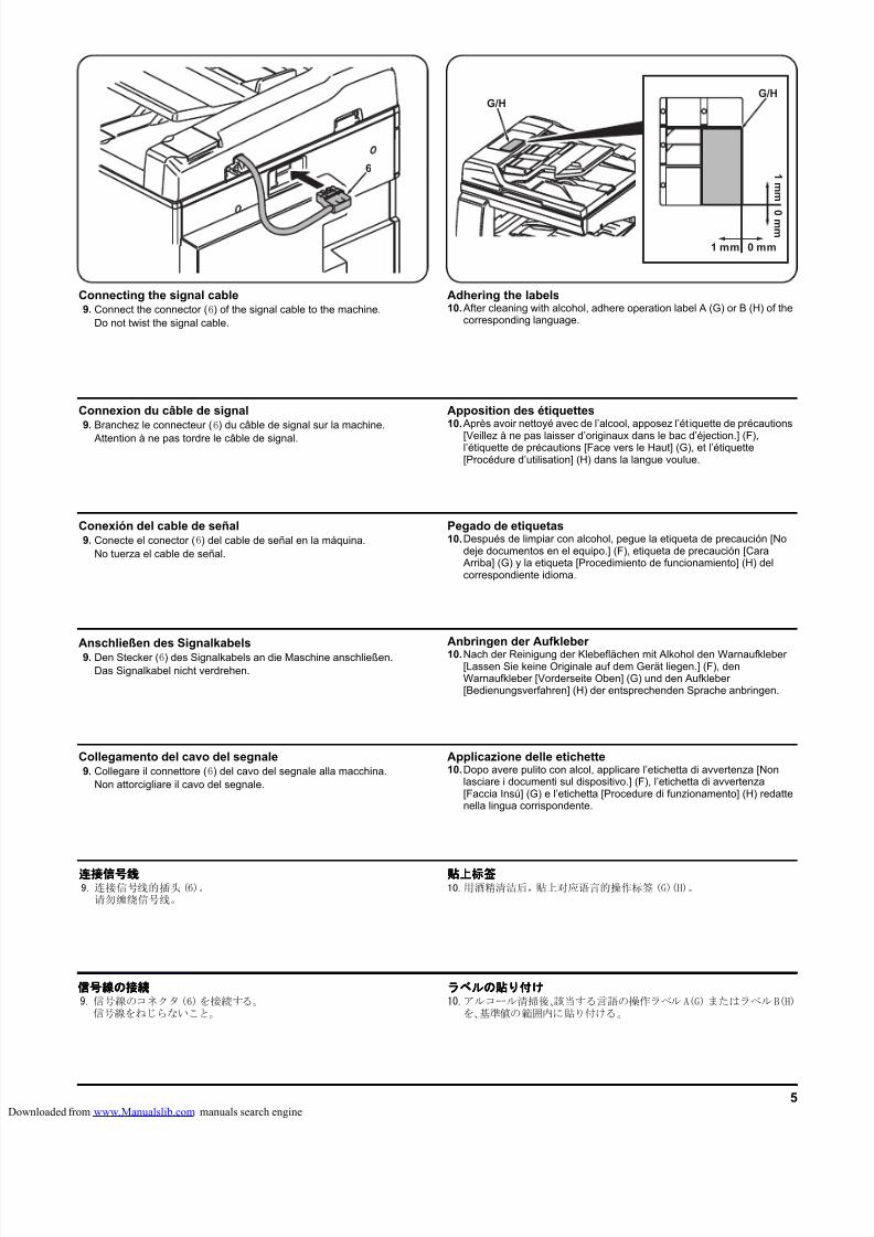
8/18/2019 taskalfa_220
http://slidepdf.com/reader/full/taskalfa220 255/3005
6
G/H
1 mm 0 mm
1 mm
0 mm
G/H
Connecting the signal cable9. Connect the connector (6) of the signal cable to the machine.
Do not twist the signal cable.
Adhering the labels10.After cleaning with alcohol, adhere operation label A (G) or B (H) of the
corresponding language.
Connexion du câble de signal9. Branchez le connecteur (6) du câble de signal sur la machine.
Attention à ne pas tordre le câble de signal.
Apposition des étiquettes10.Après avoir nettoyé avec de l’alcool, apposez l’ét iquette de précautions
[Veillez à ne pas laisser d’originaux dans le bac d’éjection.] (F),l’étiquette de précautions [Face vers le Haut] (G), et l’étiquette[Procédure d’utilisation] (H) dans la langue voulue.
Conexión del cable de señal9. Conecte el conector (6) del cable de señal en la máquina.
No tuerza el cable de señal.
Pegado de etiquetas10.Después de limpiar con alcohol, pegue la etiqueta de precaución [No
deje documentos en el equipo.] (F), etiqueta de precaución [CaraArriba] (G) y la etiqueta [Procedimiento de funcionamiento] (H) delcorrespondiente idioma.
Anschließen des Signalkabels9. Den Stecker (6) des Signalkabels an die Maschine anschließen.
Das Signalkabel nicht verdrehen.
Anbringen der Aufkleber 10.Nach der Reinigung der Klebeflächen mit Alkohol den Warnaufkleber
[Lassen Sie keine Originale auf dem Gerät liegen.] (F), denWarnaufkleber [Vorderseite Oben] (G) und den Aufkleber[Bedienungsverfahren] (H) der entsprechenden Sprache anbringen.
Collegamento del cavo del segnale9. Collegare il connettore (6) del cavo del segnale alla macchina.
Non attorcigliare il cavo del segnale.
Applicazione delle etichette10.Dopo avere pulito con alcol, applicare l’etichetta di avvertenza [Non
lasciare i documenti sul dispositivo.] (F), l’etichetta di avvertenza[Faccia Insú] (G) e l’etichetta [Procedure di funzionamento] (H) redattenella lingua corrispondente.
连接信号线连接信号线连接信号线连接信号线9. 连接信号线的插头(6)。
请勿缠绕信号线。
贴上标签贴上标签贴上标签贴上标签10.用酒精清洁后,贴上对应语言的操作标签 (G)(H)。
信号線信号線信号線信号線のののの接続接続接続接続9. 信号線のコネクタ(6)を接続する。
信号線をねじらないこと。
ラベルラベルラベルラベルのののの貼貼貼貼りりりり付付付付けけけけ10.アルコール清掃後、該当する言語の操作ラベル A(G) またはラベルB(H)
を、基準値の範囲内に貼り付ける。
loaded from www.Manualslib.com manuals search engine
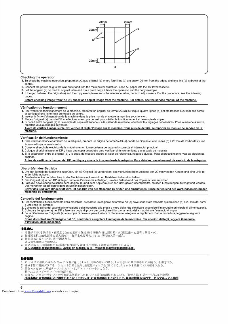
8/18/2019 taskalfa_220
http://slidepdf.com/reader/full/taskalfa220 256/3006
20mm20mm
20mm
20mm
c
b
b
a
Überprüfen des Betriebs1. Um den Betrieb der Maschine zu prüfen, ein A3-Original (a) vorbereiten, das vier Linien (b) im Abstand von 20 mm von den Kanten und eine Linie (c)
in der Mitte aufweist.2. Den Netzstecker der Maschine in die Steckdose stecken und den Betriebsschalter einschalten.3. Das Original (a) in den DP einlegen und eine Probekopie anfertigen, um den Betrieb und das Kopienmuster zu prüfen.4. Falls die Abweichung zwischen dem Original (a) und dem Kopienmuster den Bezugswert überschreitet, müssen Einstellungen durchgeführt werden.
Das Verfahren ist auf den folgenden Seiten beschrieben.Bevor das Bild vom DP geprüft wird, ist das Bild von der Maschine zu prüfen und einzustellen. Einzelheiten sind der Wartungsanleitung derMaschine zu entnehmen.
Verificación del funcionamiento1. Para verificar el funcionamiento de la máquina, prepare un origina de tamaño A3 (a) donde se dibujan cuatro líneas (b) a 20 mm de los bordes y una
línea (c) dibujada en el centro.2. Conecte el enchufe eléctrico de la máquina en un tomacorriente de la pared y conecte el interruptor principal.3. Coloque el original (a) en el DP y haga una copia de prueba para verificar el funcionamiento y una copia de muestra.4. Si la separación entre el original (a) y la copia de muestra supera el valor de referencia, haga los ajustes. Para el procedimiento, vea las siguientes
páginas.Antes de verificar la imagen del DP, verifique y ajuste la imagen desde la máquina. Para detalles, vea el manual de servicio de la máquina.
Vérification du fonctionnement1. Pour vérifier le fonctionnement de la machine, préparez un original de format A3 (a) sur lequel quatre lignes (b) ont été tracées à 20 mm des bords,
et sur lequel une ligne (c) a été tracée au centre.2. Insérer la fiche d’alimentation de la machine dans la prise murale et mettre la machine sous tension.3. Placez l’original (a) dans le DP et effectuez une copie de test pour vérifier le fonctionnement et l’exemple de copie.4. Si l’écart entre l’original (a) et l’exemple de copie est supérieur à la valeur de référence, effectuez les réglages nécessaires. Pour la marche à suivre,
reportez-vous aux pages suivantes.Avant de vérifier l’image sur le DP, vérifier et régler l’image sur la machine. Pour plus de détails, se reporter au manuel de service de lamachine.
Controllo del funzionamento1. Per controllare il funzionamento della macchina, preparare un originale di formato A3 (a) dove sono state tracciate quattro linee (b) a 20 mm dai bordi
e una linea (c) centrale.2. Collegare la spina del cavo di alimentazione della macchina alla presa a muro della rete elettrica e accendere l’interruttore principale di alimentazione.3. Collocare l’originale (a) nel DP e fare una copia di prova per controllare il funzionamento della macchina e l’esempio di copia.4. Se la differenza tra l’originale (a) e la copia di prova supera il valore di riferimento, eseguire le regolazioni. Per la procedura, leggere le seguenti
pagine.Prima di controllare l’immagine dal DP, controllare e regolare l’immagine dalla macchina. Per ulteriori dettagli, leggere il manualed’istruzioni della macchina.
操作确认操作确认操作确认操作确认1. 准备好 A3尺寸的纸张(在边起 20mm处划有 4 条线(b))和操作确认用原稿(a)(在纸张中心划有1 条线(c))。2. 将机器主机上的电源插头插入插座中,打开主电源开关。将 A3 纸张装入第一纸盒。3. 将原稿(a) 放在 DP上,进行测试复印。
确认操作和测印件的状态。4. 如果原稿 (a)和测印件的偏移超过标准值时,需要进行调整。( 调整方法参照下页以后)
确认和调整机器主机的图像后确认和调整机器主机的图像后确认和调整机器主机的图像后确认和调整机器主机的图像后,,,,必须对必须对必须对必须对 DPDPDPDP 图像进行确认图像进行确认图像进行确认图像进行确认。。。。详情请参照机器主机的维修手册详情请参照机器主机的维修手册详情请参照机器主机的维修手册详情请参照机器主机的维修手册。。。。
Checking the operation1. To check the machine operation, prepare an A3 size original (a) where four lines (b) are drawn 20 mm from the edges and one line (c) is drawn at the
center.2. Connect the power plug to the wall outlet and turn the main power switch on. Load A3 paper into the 1st level cassette.3. Set the original (a) on the DP original table and run a proof copy. Check the operation and the copy example.4. If the gap between the original (a) and the copy example exceeds the reference value, perform adjustments. For the procedure, see the following
pages.Before checking image from the DP, check and adjust image from the machine. For details, see the service manual of the machine.
動作確認動作確認動作確認動作確認1. A3サイズの用紙の端から20mmの位置に線 (b)4本と、用紙の中心に線(c)1本を引いた動作確認用の原稿 (a)を用意する。2. 機械本体の電源プラグをコンセントに差し込み、主電源スイッチを ON にする。カセット1段目に A3 用紙を入れる。3. 原稿 (a) を DP の原稿テーブルにセットし、テストコピーをおこなう。
動作およびコピーサンプルを確認する。4. 原稿 (a) とコピーサンプルのずれが基準値から外れている場合は調整をおこなう。(調整方法は、次ページ以降を参照)
機械本体機械本体機械本体機械本体のののの画像確認画像確認画像確認画像確認およびおよびおよびおよび調整調整調整調整をおこなってからをおこなってからをおこなってからをおこなってから、、、、DPDPDPDP のののの画像確認画像確認画像確認画像確認をおこなうことをおこなうことをおこなうことをおこなうこと。。。。詳細詳細詳細詳細はははは機械本体機械本体機械本体機械本体ののののサービスマニュアルサービスマニュアルサービスマニュアルサービスマニュアル参照参照参照参照
loaded from www.Manualslib.com manuals search engine
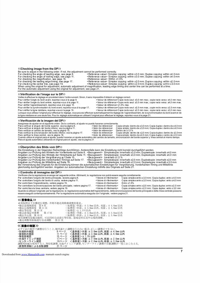
8/18/2019 taskalfa_220
http://slidepdf.com/reader/full/taskalfa220 257/3007
<<<<<<<<Überprüfen des Bilds vom DP>>>>>>>>Die Einstellung in der folgenden Reihenfolge durchführen. Anderenfalls kann die Einstellung nicht korrekt durchgeführt werden.Angaben zur Prüfung des Winkels der Vorderkante auf Seite 8. <Bezugswert> Simplexkopie: innerhalb ±3,0 mm; Duplexkopie: innerhalb ±4,0 mmAngaben zur Prüfung des Winkels der Hinterkante auf Seite 11. <Bezugswert> Simplexkopie: innerhalb ±3,0 mm; Duplexkopie: innerhalb ±4,0 mmAngaben zur Prüfung der Vergrößerung auf Seite 15. <Bezugswert> Innerhalb ±1,5 %Angaben zur Prüfung des Vorderkanten-Timings auf Seite 17. <Bezugswert> Simplexkopie: innerhalb ±2,0 mm; Duplexkopie: innerhalb ±2,0 mmAngaben zur Prüfung der Mittellinie auf Seite 19. <Bezugswert> Simplexkopie: innerhalb ±2,0 mm; Duplexkopie: innerhalb ±3,0 mmBei Verwendung des Originals für die Einstel lung können die automatischen Einstellungen für Vergrößerung, Vorderkanten-Timing und Mittelliniegleichzeitig durchgeführt werden. Angaben zur automatischen Einstellung mithilfe des Originals auf Seite 21.
<<<<<<<<Verificación de la imagen del DP>>>>>>>>Asegúrese de ajustar en el siguiente orden. De lo contrario, el ajuste no puede hacerse correctamente.Para verificar el ángulo del borde superior, vea la página 8. <Valor de referencia> Copia simple: dentro de ±3,0 mm; Copia duplex: dentro de ±4,0 mmPara verificar el ángulo del borde inferior, vea la página 11. <Valor de referencia> Copia simple: dentro de ±3,0 mm; Copia duplex: dentro de ±4,0 mmPara verificar el cambio de tamaño, vea la página 15. <Valor de referencia> Dentro de ±1,5 %Para verificar la sincronización del borde inferior, vea la página 17. <Valor de referencia> Copia simple: dentro de ±2,0 mm; Copia duplex: dentro de ±2,0 mmPara verificar la línea central, vea la página 19. <Valor de referencia> Copia simple: dentro de ±2,0 mm; Copia duplex: dentro de ±3,0 mmCuando utilice el original para el ajuste, puede hacerse un ajuste automático del cambio de tamaño, sincronización del borde superior y línea central al mismo tiempo.Para el ajuste automático utilizando el original para el ajuste, vea la página 21.
<<<<<<<<Vérification de l’image sur le DP>>>>>>>>Veillez à effectuer le réglage en procédant dans l’ordre suivant. Sinon, il sera impossible d’obtenir un réglage correct.
Pour vérifier l’angle du bord avant, reportez-vous à la page 8. <Valeur de référence>Copie recto seul: ±3,0 mm max.; copie recto verso: ±4,0 mm max.Pour vérifier l’angle du bord arrière, reportez-vous à la page 11. <Valeur de référence>Copie recto seul: ±3,0 mm max.; copie recto verso: ±4,0 mm max.Pour vérifier l’agrandissement, reportez-vous à la page 15. <Valeur de référence>±1,5% max.Pour vérifier la synchronisation du bord avant, reportez-vous à la page 17. <Valeur de référence>Copie recto seul: ±2,0 mm max.; copie recto verso: ±2,0 mm max.Pour vérif ier la ligne médiane, reportez-vous à la page 19. <Valeur de référence>Copie recto seul: ±2,0 mm max.; copie recto verso: ±3,0 mm max.Lorsque vous utilisez l’original pour effectuer le réglage, vous pouvez effectuer automatiquement le réglage de l’agrandissement, de la synchronisation du bord avant et dela ligne médiane en une seule fois. Pour le réglage automatique en utilisant l’original pour effectuer le réglage, reportez-vous à la page 21.
<<<<<<<<Controllo di immagine dal DP>>>>>>>>Verificare che la regolazione avvenga nel seguente ordine. Altrimenti, la regolazione non potrà essere seguita correttamente.Per controllare l’angolo del bordo principale, vedere pagina 8. <Valore di riferimento> Copia simplex:entro ±3,0 mm; Copia duplex: entro ±4,0 mmPer controllare l’angolo del bordo di uscita, vedere pagina 11. <Valore di riferimento> Copia simplex:entro ±3,0 mm; Copia duplex: entro ±4,0 mmPer controllare l’ingrandimento, vedere pagina 15. <Valore di riferimento> Entro ±1,5%Per controllare la sincronizzazione del bordo principale, vedere pagina 17. <Valore di riferimento> Copia simplex:entro ±2,0 mm; Copia duplex: entro ±2,0 mmPer control lare la l inea centrale, vedere pagina 19. <Valore di ri ferimento> Copia simplex:entro ±2,0 mm; Copia duplex: entro ±3,0 mmQuando si utilizza l’originale per la regolazione, la regolazione automatica dell’ingrandimento, della sincronizzazione del bordo principale e della linea centrale possonoessere eseguiti contemporaneamente. Per la regolazione automatica eseguita con l’originale, vedere pagina 21.
<<<<<<<<图像确认图像确认图像确认图像确认>>>>>>>>必须按照以下步骤进行调整,否则不能达到准确调整的要求。·确认前端倾斜度 第 8 页 < 标准值 >单面 :± 3.0mm 以内、双面 :± 4.0mm 以内·确认后端倾斜度 第 11 页 < 标准值 >单面 :± 3.0mm 以内、双面 :± 4.0mm 以内·确认等倍值 第 15 页 < 标准值 >± 1.5%以内·确认前端定时调整 第 17页 < 标准值 >单面 :± 2.0mm以内、双面 :± 2.0mm以内·确认中心线 第 19 页 < 标准值 >单面 :± 2.0mm以内、双面 :± 3.0mm 以内使用调整用原稿功能时,可以同时自动进行等倍值、前端定时以及中心线的调整。·通过调整用原稿进行自动调整 第21 页
<<<<<<<< 画像画像画像画像のののの確認確認確認確認 >>>>>>>>必ず下記の順序で調整を行うこと。順序通りに調整を行わない場合、正しい調整ができない。
・先端斜め確認 8 ページ <基準値>片面:± 3.0mm 以内、両面:± 4.0mm 以内・後端斜め確認 11 ページ <基準値>片面:± 3.0mm 以内、両面:± 4.0mm 以内・等倍度確認 15 ページ <基準値>± 1.5% 以内・先端タイミング確認 17ページ <基準値>片面:± 2.0mm 以内、両面:± 2.0mm 以内・センターライン確認 19ページ <基準値>片面:± 2.0mm 以内、両面:± 3.0mm 以内調整用原稿を使用すると、等倍度調整、先端タイミング調整、センターライン調整の自動調整が一度におこなえる。
・調 整用 原稿に よる自動 調整 21 ペ ージ
<<<<<<<<Checking image from the DP>>>>>>>>Be sure to adjust in the following order. If not, the adjustment cannot be performed correctly.For checking the angle of leading edge, see page 8. <Reference value> Simplex copying: within ±3.0 mm; Duplex copying: within ±4.0 mmFor checking the angle of trailing edge, see page 11. <Reference value> Simplex copying: within ±3.0 mm; Duplex copying: within ±4.0 mmFor checking the magnification, see page 15. <Reference value> Within ±1.5%For checking the leading edge timing, see page 17. <Reference value> Simplex copying: within ±2.0 mm; Duplex copying: within ±2.0 mmFor checking the center line, see page 19. <Reference value> Simplex copying: within ±2.0 mm; Duplex copying: within ±3.0 mmWhen using the original for adjustment, automatic adjustment of magnification, leading edge timing and center line can be performed at a time.For the automatic adjustment using the original for adjustment, see page 21.
loaded from www.Manualslib.com manuals search engine
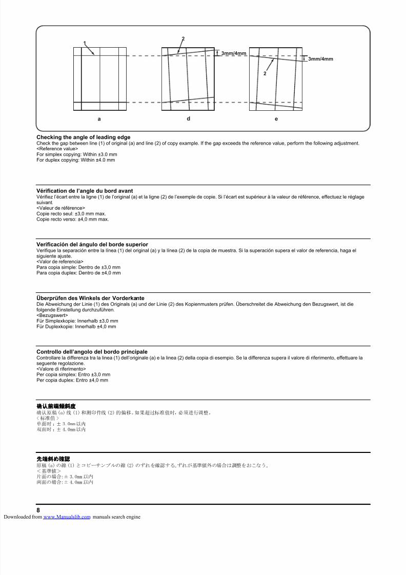
8/18/2019 taskalfa_220
http://slidepdf.com/reader/full/taskalfa220 258/3008
a
1
e
2
d
2
3mm/4mm3mm/4mm
Überprüfen des Winkels der VorderkanteDie Abweichung der Linie (1) des Originals (a) und der Linie (2) des Kopienmusters prüfen. Überschreitet die Abweichung den Bezugswert, ist diefolgende Einstellung durchzuführen.<Bezugswert>Für Simplexkopie: Innerhalb ±3,0 mmFür Duplexkopie: Innerhalb ±4,0 mm
Verificación del ángulo del borde superior Verifique la separación entre la línea (1) del original (a) y la línea (2) de la copia de muestra. Si la superación supera el valor de referencia, haga elsiguiente ajuste.<Valor de referencia>Para copia simple: Dentro de ±3,0 mmPara copia duplex: Dentro de ±4,0 mm
Vérification de l’angle du bord avantVérifiez l’écart entre la ligne (1) de l’original (a) et la ligne (2) de l’exemple de copie. Si l’écart est supérieur à la valeur de référence, effectuez le réglage
suivant.<Valeur de référence>Copie recto seul: ±3,0 mm max.Copie recto verso: ±4,0 mm max.
Controllo dell’angolo del bordo principaleControllare la differenza tra la linea (1) dell’originale (a) e la linea (2) della copia di esempio. Se la differenza supera il valore di riferimento, effettuare laseguente regolazione.<Valore di riferimento>Per copia simplex: Entro ±3,0 mmPer copia duplex: Entro ±4,0 mm
确认前端倾斜度确认前端倾斜度确认前端倾斜度确认前端倾斜度确认原稿(a)线 (1)和测印件线 (2)的偏移。如果超过标准值时,必须进行调整。<标准值 >单面时 :± 3.0mm以内双面时 :± 4.0mm以内
先端斜先端斜先端斜先端斜めめめめ確認確認確認確認原稿(a)の線 (1)とコピーサンプルの線(2)のずれを確認する。ずれが基準値外の場合は調整をおこなう。<基準値>片面の場合:± 3.0mm以内両面の場合:± 4.0mm以内
Checking the angle of leading edgeCheck the gap between line (1) of original (a) and line (2) of copy example. If the gap exceeds the reference value, perform the following adjustment.<Reference value>For simplex copying: Within ±3.0 mmFor duplex copying: Within ±4.0 mm
loaded from www.Manualslib.com manuals search engine
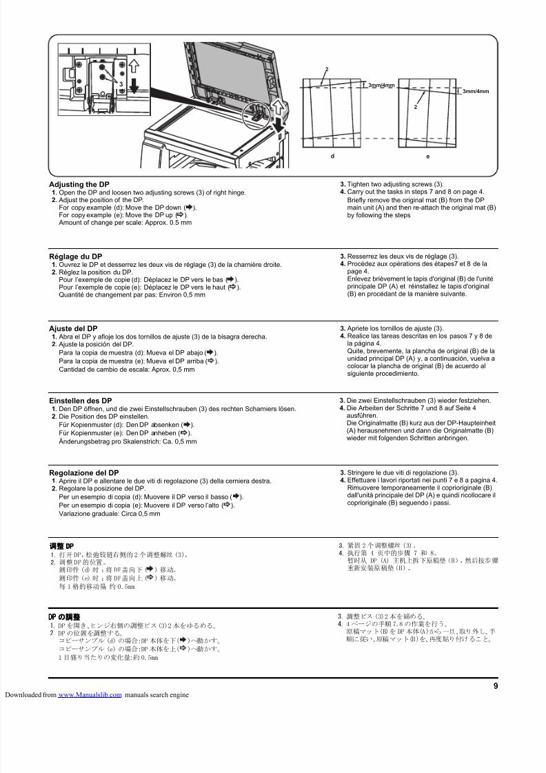
8/18/2019 taskalfa_220
http://slidepdf.com/reader/full/taskalfa220 259/3009
e
2
d
2
3mm/4mm3mm/4mm
3
Einstellen des DP1. Den DP öffnen, und die zwei Einstellschrauben (3) des rechten Scharniers lösen.2. Die Position des DP einstellen.
Für Kopienmuster (d): Den DP absenken ( ).Für Kopienmuster (e): Den DP anheben ( ).Änderungsbetrag pro Skalenstrich: Ca. 0,5 mm
3. Die zwei Einstellschrauben (3) wieder festziehen.
4. Die Arbeiten der Schritte 7 und 8 auf Seite 4ausführen.Die Originalmatte (B) kurz aus der DP-Haupteinheit(A) herausnehmen und dann die Originalmatte (B)wieder mit folgenden Schritten anbringen.
Ajuste del DP1. Abra el DP y afloje los dos tornillos de ajuste (3) de la bisagra derecha.2. Ajuste la posición del DP.
Para la copia de muestra (d): Mueva el DP abajo ( ).Para la copia de muestra (e): Mueva el DP arriba ( ).Cantidad de cambio de escala: Aprox. 0,5 mm
3. Apriete los tornillos de ajuste (3).4. Realice las tareas descritas en los pasos 7 y 8 de
la página 4.Quite, brevemente, la plancha de original (B) de launidad principal DP (A) y, a continuación, vuelva acolocar la plancha de original (B) de acuerdo alsiguiente procedimiento.
Réglage du DP1. Ouvrez le DP et desserrez les deux vis de réglage (3) de la charnière droite.
2. Réglez la position du DP.Pour l’exemple de copie (d): Déplacez le DP vers le bas ( ).Pour l’exemple de copie (e): Déplacez le DP vers le haut ( ).Quantité de changement par pas: Environ 0,5 mm
3. Resserrez les deux vis de réglage (3).4. Procédez aux opérations des étapes7 et 8 de la
page 4.Enlevez brièvement le tapis d'original (B) de l'unitéprincipale DP (A) et réinstallez le tapis d'original(B) en procédant de la manière suivante.
Regolazione del DP1. Aprire il DP e allentare le due viti di regolazione (3) della cerniera destra.2. Regolare la posizione del DP.
Per un esempio di copia (d): Muovere il DP verso il basso ( ).Per un esempio di copia (e): Muovere il DP verso l’alto ( ).Variazione graduale: Circa 0,5 mm
3. Stringere le due viti di regolazione (3).4. Effettuare i lavori riportati nei punti 7 e 8 a pagina 4.
Rimuovere temporaneamente il coprioriginale (B)dall'unità principale del DP (A) e quindi ricollocare ilcoprioriginale (B) seguendo i passi.
调整调整调整调整 DPDPDPDP1. 打开 DP,松弛铰链右侧的2 个调整螺丝 (3)。2. 调整DP的位置。
测印件 (d) 时 :将 DP盖向下( ) 移动。
测印件 (e) 时 :将 DP盖向上( ) 移动。
每 1 格的移动量:约 0.5mm
3. 紧固2个调整螺丝 (3)。4. 执行第 4 页中的步骤 7 和 8。
暂时从 DP (A) 主机上拆下原稿垫(B),然后按步骤重新安装原稿垫(B)。
DPDPDPDP のののの調整調整調整調整1. DP を開き、ヒンジ右側の調整ビス(3)2 本をゆるめる。2. DPの位置を調整する。
コピーサンプル (d) の場合:DP 本体を下( )へ動かす。
コピーサンプル (e) の場合:DP 本体を上( )へ動かす。
1 目盛り当たりの変化量:約 0.5mm
3. 調整ビス (3)2本を締める。4. 4 ページの手順7.8 の作業を行う。
原稿マット(B)を DP本体(A)から一旦、取り外し、手順に従い、原稿マット(B)を、再度貼り付けること。
Adjusting the DP1. Open the DP and loosen two adjusting screws (3) of right hinge.2. Adjust the position of the DP.
For copy example (d): Move the DP down ( ).For copy example (e): Move the DP up ( ).Amount of change per scale: Approx. 0.5 mm
3. Tighten two adjusting screws (3).4. Carry out the tasks in steps 7 and 8 on page 4.
Briefly remove the original mat (B) from the DPmain unit (A) and then re-attach the original mat (B)by following the steps
loaded from www.Manualslib.com manuals search engine
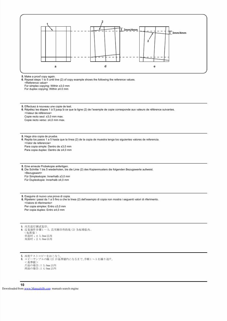
8/18/2019 taskalfa_220
http://slidepdf.com/reader/full/taskalfa220 260/30010
a
1
e
2
d
2
3mm/4mm3mm/4mm
5. Eine erneute Probekopie anfertigen.
6. Die Schritte 1 bis 5 wiederholen, bis die Linie (2) des Kopienmusters die folgenden Bezugswerte aufweist.<Bezugswert>Für Simplexkopie: Innerhalb ±3,0 mmFür Duplexkopie: Innerhalb ±4,0 mm
5. Haga otra copia de prueba.6. Repita los pasos 1 a 5 hasta que la línea (2) de la copia de muestra tenga los siguientes valores de referencia.
<Valor de referencia>Para copia simple: Dentro de ±3,0 mmPara copia duplex: Dentro de ±4,0 mm
5. Effectuez à nouveau une copie de test.6. Répétez les étapes 1 à 5 jusqu’à ce que la ligne (2) de l’exemple de copie corresponde aux valeurs de référence suivantes.
<Valeur de référence>Copie recto seul: ±3,0 mm max.Copie recto verso: ±4,0 mm max.
5. Eseguire di nuovo una prova di copia.6. Ripetere i passi da 1 a 5 fino a che la linea (2) dell’esempio di copia non mostra i seguenti valori di riferimento.
<Valore di riferimento>Per copia simplex: Entro ±3,0 mmPer copia duplex: Entro ±4,0 mm
5. 再次进行测试复印。6. 反复操作步骤1 ~ 5,直至测印件的线(2) 为标准值内。
< 标准值 >单面时 :± 3.0mm以内双面时 :± 4.0mm以内
5. 再度テストコピーをおこなう。6. コピーサンプルの線 (2)が基準値内になるまで、手順1~ 5 を繰り返す。
<基準値>片面の場合:± 3.0mm 以内両面の場合:± 4.0mm 以内
5. Make a proof copy again.6. Repeat steps 1 to 5 until line (2) of copy example shows the following the reference values.
<Reference value>For simplex copying: Within ±3.0 mmFor duplex copying: Within ±4.0 mm
loaded from www.Manualslib.com manuals search engine
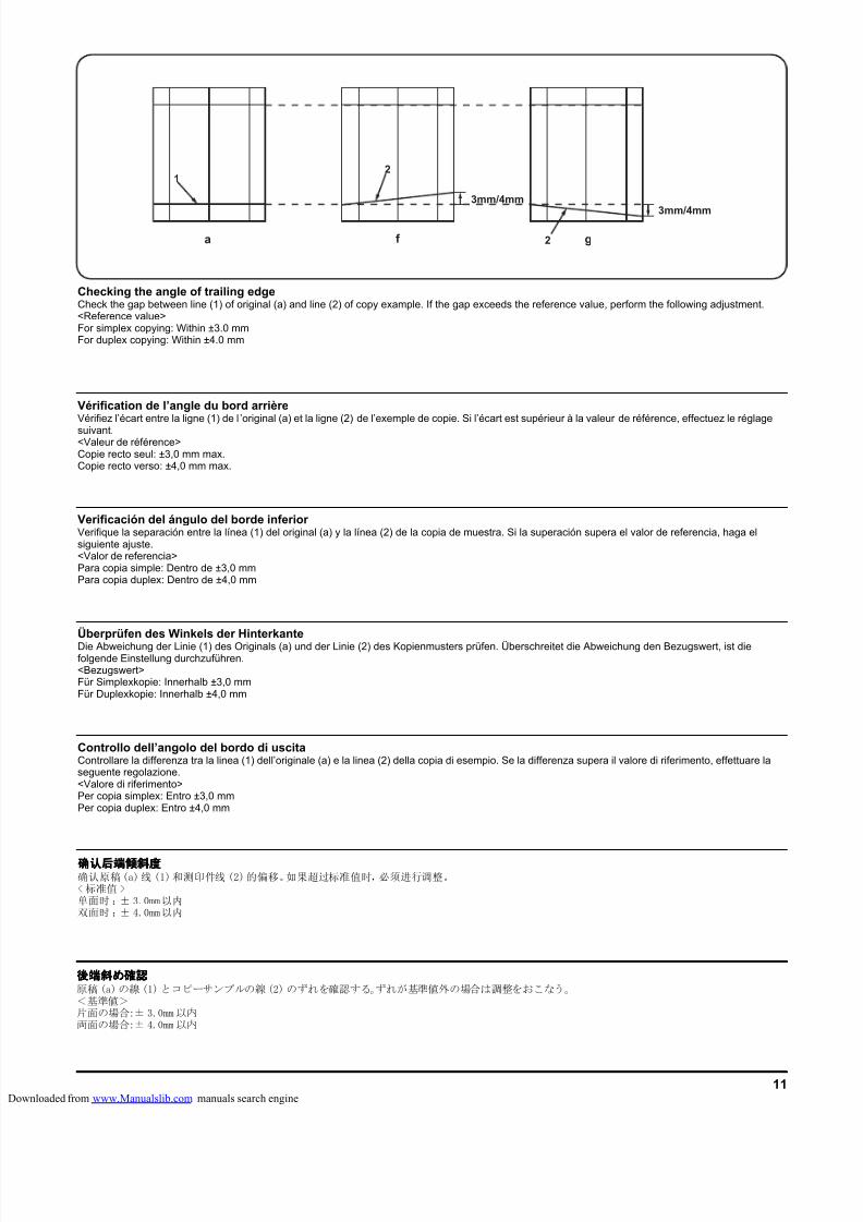
8/18/2019 taskalfa_220
http://slidepdf.com/reader/full/taskalfa220 261/30011
a
1
g2f
2
3mm/4mm
3mm/4mm
Überprüfen des Winkels der HinterkanteDie Abweichung der Linie (1) des Originals (a) und der Linie (2) des Kopienmusters prüfen. Überschreitet die Abweichung den Bezugswert, ist diefolgende Einstellung durchzuführen.<Bezugswert>Für Simplexkopie: Innerhalb ±3,0 mmFür Duplexkopie: Innerhalb ±4,0 mm
Verificación del ángulo del borde inferior Verifique la separación entre la línea (1) del original (a) y la línea (2) de la copia de muestra. Si la superación supera el valor de referencia, haga elsiguiente ajuste.<Valor de referencia>Para copia simple: Dentro de ±3,0 mmPara copia duplex: Dentro de ±4,0 mm
Vérification de l’angle du bord arrièreVérifiez l’écart entre la ligne (1) de l ’original (a) et la ligne (2) de l’exemple de copie. Si l’écart est supérieur à la valeur de référence, effectuez le réglage
suivant.<Valeur de référence>Copie recto seul: ±3,0 mm max.Copie recto verso: ±4,0 mm max.
Controllo dell’angolo del bordo di uscitaControllare la differenza tra la linea (1) dell’originale (a) e la linea (2) della copia di esempio. Se la differenza supera il valore di riferimento, effettuare laseguente regolazione.<Valore di riferimento>Per copia simplex: Entro ±3,0 mmPer copia duplex: Entro ±4,0 mm
确认后端倾斜度确认后端倾斜度确认后端倾斜度确认后端倾斜度确认原稿(a)线 (1)和测印件线 (2)的偏移。如果超过标准值时,必须进行调整。<标准值 >单面时 :± 3.0mm以内双面时 :± 4.0mm以内
後端斜後端斜後端斜後端斜めめめめ確認確認確認確認原稿(a)の線 (1)とコピーサンプルの線(2)のずれを確認する。ずれが基準値外の場合は調整をおこなう。<基準値>片面の場合:± 3.0mm以内両面の場合:± 4.0mm以内
Checking the angle of trailing edgeCheck the gap between line (1) of original (a) and line (2) of copy example. If the gap exceeds the reference value, perform the following adjustment.<Reference value>For simplex copying: Within ±3.0 mmFor duplex copying: Within ±4.0 mm
loaded from www.Manualslib.com manuals search engine
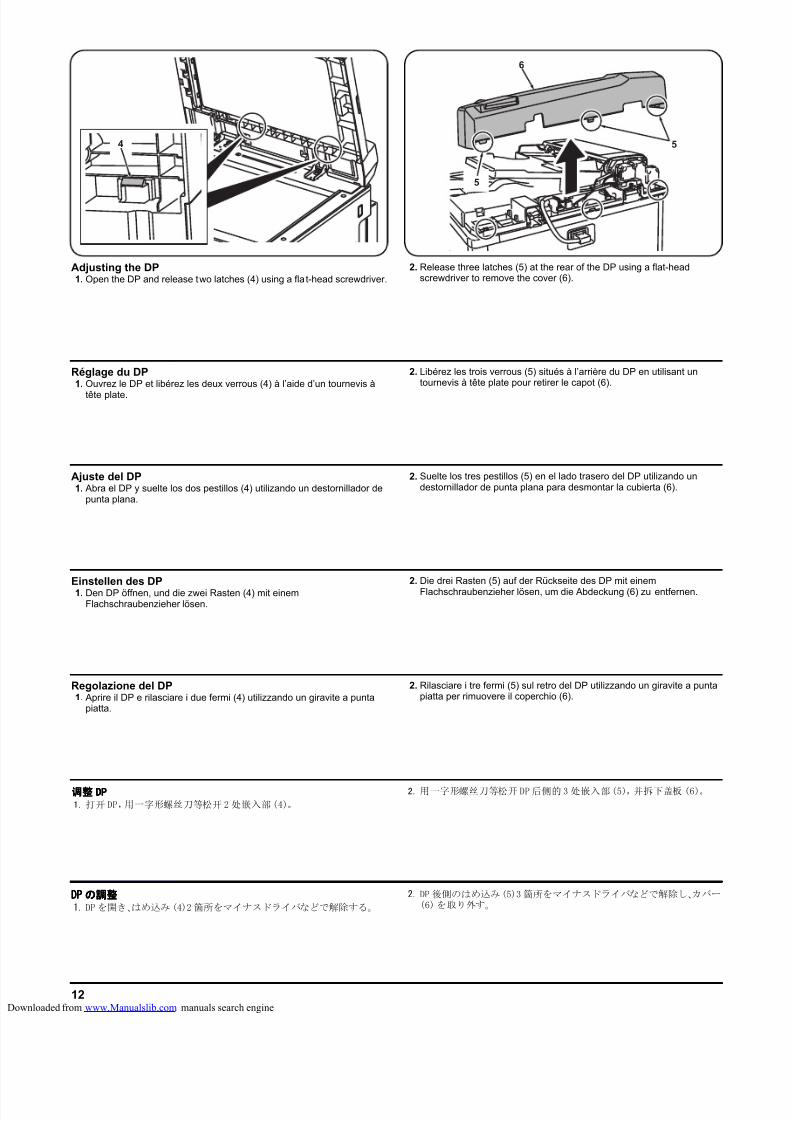
8/18/2019 taskalfa_220
http://slidepdf.com/reader/full/taskalfa220 262/30012
6
5
54
Einstellen des DP1. Den DP öffnen, und die zwei Rasten (4) mit einem
Flachschraubenzieher lösen.
2. Die drei Rasten (5) auf der Rückseite des DP mit einem
Flachschraubenzieher lösen, um die Abdeckung (6) zu entfernen.
Ajuste del DP1. Abra el DP y suelte los dos pestillos (4) utilizando un destornillador de
punta plana.
2. Suelte los tres pestillos (5) en el lado trasero del DP utilizando undestornillador de punta plana para desmontar la cubierta (6).
Réglage du DP1. Ouvrez le DP et libérez les deux verrous (4) à l’aide d’un tournevis à
tête plate.
2. Libérez les trois verrous (5) situés à l’arrière du DP en utilisant untournevis à tête plate pour retirer le capot (6).
Regolazione del DP1. Aprire il DP e rilasciare i due fermi (4) utilizzando un giravite a punta
piatta.
2. Rilasciare i tre fermi (5) sul retro del DP utilizzando un giravite a puntapiatta per rimuovere il coperchio (6).
调整调整调整调整 DPDPDPDP1. 打开 DP,用一字形螺丝刀等松开2 处嵌入部(4)。
2. 用一字形螺丝刀等松开 DP后侧的3 处嵌入部(5),并拆下盖板 (6)。
DPDPDPDP のののの調整調整調整調整1. DP を開き、はめ込み(4)2 箇所をマイナスドライバなどで解除する。
2. DP 後側のはめ込み(5)3 箇所をマイナスドライバなどで解除し、カバー(6)を取り外す。
Adjusting the DP1. Open the DP and release two latches (4) using a fla t-head screwdriver.
2. Release three latches (5) at the rear of the DP using a flat-headscrewdriver to remove the cover (6).
loaded from www.Manualslib.com manuals search engine
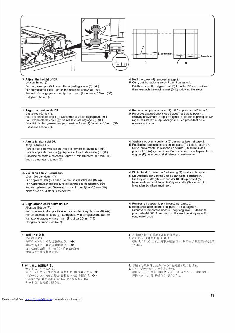
8/18/2019 taskalfa_220
http://slidepdf.com/reader/full/taskalfa220 263/30013
g2f
2
3mm/4mm3mm/4mm
8
7
109
3. Die Höhe des DP einstellen.Lösen Sie die Mutter (7).Für Kopienmuster (f): Lösen Sie die Einstellschraube (8). ( )Für Kopienmuster (g): Die Einstellschraube (8) festziehen. ( )Änderungsbetrag pro Skalenstrich: ca. 1 mm (9)/ca. 0,5 mm (10)Ziehen Sie die Mutter (7) wieder fest.
4. Die in Schritt 2 entfernte Abdeckung (6) wieder anbringen.
5. Die Arbeiten der Schritte 7 und 8 auf Seite 4 ausführen.Die Originalmatte (B) kurz aus der DP-Haupteinheit (A)herausnehmen und dann die Originalmatte (B) wieder mitfolgenden Schritten anbringen.
3. Ajuste la altura del DP.Afloje la tuerca (7).Para la copia de muestra (f): Afloje el tornillo de ajuste (8). ( )Para la copia de muestra (g): Apriete el tornillo de ajuste (8). ( )Cantidad de cambio de escala: Aprox. 1 mm (9)/aprox. 0,5 mm (10)Vuelva a apretar la tuerca (7).
4. Vuelva a colocar la cubierta (6) desmontada en el paso 2.5. Realice las tareas descritas en los pasos 7 y 8 de la página 4.
Quite, brevemente, la plancha de original (B) de la unidadprincipal DP (A) y, a continuación, vuelva a colocar la plancha deoriginal (B) de acuerdo al siguiente procedimiento.
3. Réglez la hauteur du DP.Desserrez l’écrou (7).
Pour l’exemple de copie (f): Desserrez la vis de réglage (8). ( )Pour l’exemple de copie (g): Serrez la vis de réglage (8). ( )Quantité de changement par pas: environ 1 mm (9) / environ 0,5 mm (10)Resserrez l’écrou (7).
4. Remettez en place le capot (6) retiré auparavant à l’étape 2.5. Procédez aux opérations des étapes7 et 8 de la page 4.
Enlevez brièvement le tapis d'original (B) de l'unité principale DP(A) et réinstallez le tapis d'original (B) en procédant de lamanière suivante.
3. Regolazione dell’altezza del DPAllentare il dado (7).Per un esempio di copia (f): Allentare la vite di regolazione (8). ( )Per un esempio di copia (g): Stringere la vite di regolazione (8). ( )Variazione graduale: circa 1 mm (9) / circa 0,5 mm (10)Stringere di nuovo il dado (7).
4. Reinserire il coperchio (6) rimosso nel passo 2.5. Effettuare i lavori riportati nei punti 7 e 8 a pagina 4.
Rimuovere temporaneamente il coprioriginale (B) dall'unitàprincipale del DP (A) e quindi ricollocare il coprioriginale (B)seguendo i passi.
3.3.3.3. 调整调整调整调整DPDPDPDP的高度的高度的高度的高度。。。。松弛螺母(7)。测印件 (f)时 :松弛调整螺丝(8)。( )
测印件 (g)时 :紧固调整螺丝(8)。( )
每 1 格的移动量 :约 1mm(9)/约 0.5mm(10)将螺母(7)按原样紧固好。
4. 在步骤 2拆下的盖板 (6) 按原样装好。5. 执行第 4 页中的步骤 7 和 8。
暂时从 DP (A) 主机上拆下原稿垫(B),然后按步骤重新安装原稿垫(B)。
3.3.3.3. DPDPDPDP のののの高高高高さをさをさをさを調整調整調整調整するするするする。。。。ナット(7)をゆるめる。コピーサンプル(f)の場合:調整ビス(8)をゆるめる。( )
コピーサンプル(g)の場合:調整ビス(8)を締める。( )
1 目盛り当たりの変化量:約 1mm(9)/約 0.5mm(10)ナット(7)を元通り締める。
4. 手順2で取り外したカバー(6)を元通り取り付ける。5. 4 ページの手順7.8 の作業を行う。
原稿マット(B)を DP本体(A)から一旦、取り外し、手順に従い、原稿マット(B)を、再度貼り付けること。
3. Adjust the height of DP.Loosen the nut (7).For copy example (f): Loosen the adjusting screw (8). ( )For copy example (g): Tighten the adjusting screw (8). ( )Amount of change per scale: Approx. 1 mm (9)/ Approx. 0.5 mm (10)Retighten the nut (7).
4. Refit the cover (6) removed in step 2.5. Carry out the tasks in steps 7 and 8 on page 4.
Briefly remove the original mat (B) from the DP main unit andthen re-attach the original mat (B) by following the steps
loaded from www.Manualslib.com manuals search engine
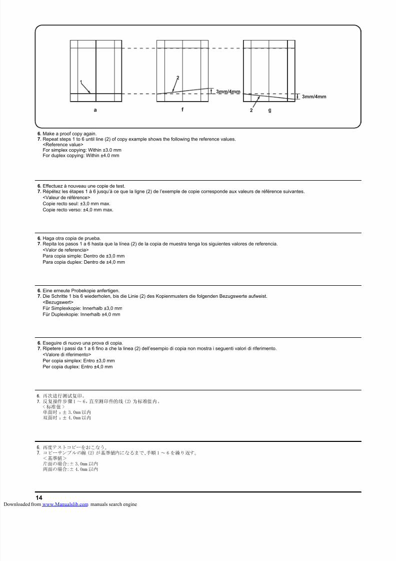
8/18/2019 taskalfa_220
http://slidepdf.com/reader/full/taskalfa220 264/30014
a
1
g2f
2
3mm/4mm
3mm/4mm
6. Eine erneute Probekopie anfertigen.
7. Die Schritte 1 bis 6 wiederholen, bis die Linie (2) des Kopienmusters die folgenden Bezugswerte aufweist.<Bezugswert>Für Simplexkopie: Innerhalb ±3,0 mmFür Duplexkopie: Innerhalb ±4,0 mm
6. Haga otra copia de prueba.7. Repita los pasos 1 a 6 hasta que la línea (2) de la copia de muestra tenga los siguientes valores de referencia.
<Valor de referencia>Para copia simple: Dentro de ±3,0 mmPara copia duplex: Dentro de ±4,0 mm
6. Effectuez à nouveau une copie de test.7. Répétez les étapes 1 à 6 jusqu’à ce que la ligne (2) de l’exemple de copie corresponde aux valeurs de référence suivantes.
<Valeur de référence>Copie recto seul: ±3,0 mm max.Copie recto verso: ±4,0 mm max.
6. Eseguire di nuovo una prova di copia.7. Ripetere i passi da 1 a 6 fino a che la linea (2) dell’esempio di copia non mostra i seguenti valori di riferimento.
<Valore di riferimento>Per copia simplex: Entro ±3,0 mmPer copia duplex: Entro ±4,0 mm
6. 再次进行测试复印。7. 反复操作步骤1 ~ 6,直至测印件的线(2) 为标准值内。
< 标准值 >单面时 :± 3.0mm以内双面时 :± 4.0mm以内
6. 再度テストコピーをおこなう。7. コピーサンプルの線 (2)が基準値内になるまで、手順1 ~ 6を繰り返す。
<基準値>片面の場合:± 3.0mm 以内両面の場合:± 4.0mm 以内
6. Make a proof copy again.7. Repeat steps 1 to 6 until line (2) of copy example shows the following the reference values.
<Reference value>For simplex copying: Within ±3.0 mmFor duplex copying: Within ±4.0 mm
loaded from www.Manualslib.com manuals search engine
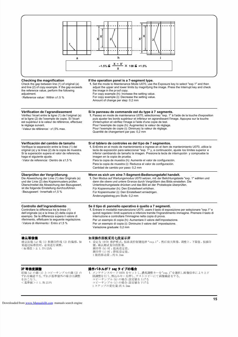
8/18/2019 taskalfa_220
http://slidepdf.com/reader/full/taskalfa220 265/30015
a
1
h
2XX'
i
X'X
X'X100 +1.5%-1.5%
X
2
Überprüfen der VergrößerungDie Abweichung der Linie (1) des Originals (a)und der Linie (2) des Kopienmusters prüfen.Überschreitet die Abweichung den Bezugswert,ist die folgende Einstellung durchzuführen.<Bezugswert> Innerhalb ±1,5 %
Wenn es sich um eine 7-Segment-Bedienungstafel handelt.1. Den Modus auf Wartungsmodus U070 setzen, mit der Belichtungstaste "exp. 1" wählen und
dann die obere und untere Grenze durch Vergrößern des Bilds einstellen. DieUnterbrechungstaste drücken und das Bild an der Probekopie überprüfen.Für Kopienmuster (h): Den Einstellwert erhöhen.Für Kopienmuster (i): Den Einstellwert erniedrigen.Änderungsbetrag pro Stufe: 0,2 mm
.
Verificación del cambio de tamañoVerifique la separación entre la línea (1) deloriginal (a) y la línea (2) de la copia de muestra.Si la superación supera el valor de referencia,haga el siguiente ajuste.<Valor de referencia> Dentro de ±1,5 %
Si el tablero de controles es del tipo de 7 segmentos.1. EnEntre en el modo de mantenimiento e ingrese en el ítem de mantenimiento U070, utilice la
tecla de exposición para seleccionar "exp. 1" y, a continuación, ajuste los límites superior einferior cambiando de tamaño la imagen. Presione la tecla de interrupción y compruebe laimagen en la copia de prueba.Para la copia de muestra (h): Aumente el valor de configuración.Para la copia de muestra (i): Reduzca el valor de configuración.Cantidad de cambio por paso: 0,2 mm
Vérification de l’agrandissementVérifiez l’écart entre la ligne (1) de l’original (a)
et la ligne (2) de l’exemple de copie. Si l’écartest supérieur à la valeur de référence, effectuezle réglage suivant.<Valeur de référence> ±1,5% max.
Si le panneau de commande est du type à 7 segments.1. Passez en mode de maintenance U070, sélectionnez "exp. 1" à l'aide de la touche d'exposition
puis ajuster les bords supérieur et inférieur en agrandissant l'image. Appuyez sur la touched'interruption et vérifiez l'image à l'aide d'une copie de test.Pour l’exemple de copie (h): Augmentez la valeur de réglage.Pour l’exemple de copie (i): Diminuez la valeur de réglage.Quantité de changement par pas: 0,2 mm
Controllo dell’ingrandimentoControllare la differenza tra la linea (1)dell’originale (a) e la linea (2) della copia diesempio. Se la differenza supera il valore diriferimento, effettuare la seguente regolazione.<Valore di riferimento> Entro ±1,5 %
Se il tipo di pannello operativo è quello a 7 segmenti.1. Entrare in modalità manutenzione U070, usare il tasto di esposizione per selezionare "exp.1" e
quindi regolare i limiti superiore e inferiore tramite l'ingrandimento immagine. Premere il tasto diinterruzione e controllare l'immagine nella copia di prova.Per un esempio di copia (h): Aumentare il valore dell’impostazione.Per un esempio di copia (i): Diminuire il valore dell’ impostazione.Variazione graduale: 0,2 mm
确认等倍值确认等倍值确认等倍值确认等倍值确认原稿(a) 线 (1) 和测印件线(2) 的偏移。如果超过标准值时,必须进行调整。<标准值 >± 1.5%以内
如果操作面板采用七段显示屏如果操作面板采用七段显示屏如果操作面板采用七段显示屏如果操作面板采用七段显示屏1. 设定为 U070 维护模式,按浓淡控制键选择“exp.1”,然后放大图像,调整上、下限值。按插印
键,确认测试复印的图像。测印件(h)时 :提高设定值。测印件(i)时 :降低设定值。1级的移动量 :约 0.2mm
DPDPDPDP 等倍度調整等倍度調整等倍度調整等倍度調整原稿(a) の線(1) とコピーサンプルの線(2) のずれを確認する。ずれが基準値外の場合は調整をおこなう。<基準値>± 1.5% 以内
操作操作操作操作パネルパネルパネルパネルがががが7777 segsegsegseg タイプタイプタイプタイプのののの場合場合場合場合1. メンテナンスモード U070 をセットし、濃度調整キーを“exp.1”を選択し画像倍率により上下
限調整を行う。割込みキーを押し、テストコピーにて画像確認をする。コピーサンプル(h)の場合:設定値を上げるコピーサンプル(i)の場合:設定値を下げる1 ステップの変化量:約 0.2mm
Checking the magnificationCheck the gap between line (1) of original (a)and line (2) of copy example. If the gap exceedsthe reference value, perform the followingadjustment.<Reference value> Within ±1.5 %
If the operation panel is a 7-segment type.1. Set the mode to Maintenance Mode U070, use the Exposure key to select "exp.1" and then
adjust the upper and lower limits by magnifying the image. Press the Interrupt key and checkthe image in the proof copy.For copy example (h): Increase the setting value.For copy example (i): Decrease the setting value.Amount of change per step: 0.2 mm
loaded from www.Manualslib.com manuals search engine
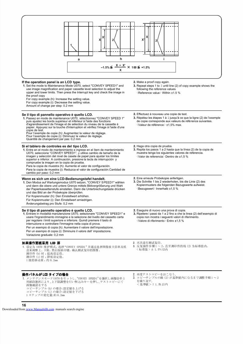
8/18/2019 taskalfa_220
http://slidepdf.com/reader/full/taskalfa220 266/30016
a
1
h
2XX'
i
X'X
X'X100 +1.5%-1.5%
X
2
Wenn es sich um eine LCD-Bedienungstafel handelt.1. Den Modus auf Wartungsmodus U070 setzen, "CONVEY SPEED1" wählen
und dann die obere und untere Grenze mittels Bildvergrößerung und Wahlder Papierkassettenstufe einstellen. Dann die Unterbrechungstaste drückenund das Bild an der Probekopie überprüfen.Für Kopienmuster (h): Den Einstellwert erhöhen.Für Kopienmuster (i): Den Einstellwert erniedrigen.Änderungsbetrag pro Stufe: 0,2 mm
2. Eine erneute Probekopie anfertigen.
3. Die Schritte 1 bis 2 wiederholen, bis die Linie (2) desKopienmusters die folgenden Bezugswerte aufweist.<Bezugswert> Innerhalb ±1,5 %
Si el tablero de controles es del tipo LCD.1. Entre en el modo de mantenimiento e ingrese en el ítem de mantenimiento
U070, seleccione “CONVEY SPEED1”, y utilice cambio de tamaño de laimagen y selección del nivel de casete de papel para ajustar los límitessuperior e inferior. A continuación, presione la tecla de interrupción ycompruebe la imagen en la copia de prueba.Para la copia de muestra (h): Aumente el valor de configuración.Para la copia de muestra (i): Reduzca el valor de configuración.Cantidad decambio por paso: 0,2 mm
2. Haga otra copia de prueba.3. Repita los pasos 1 a 2 hasta que la línea (2) de la copia de
muestra tenga los siguientes valores de referencia.<Valor de referencia> Dentro de ±1,5 %
Se il tipo di pannello operativo è quello LCD.1. Passez en mode de maintenance U070, sélectionnez "CONVEY SPEED 1"
puis ajustez les bords supérieur et inférieur à l'aide des fonctionsd'agrandissement de l'image et de sélection du niveau de la cassette àpapier. Appuyez sur la touche d'interruption et vérifiez l'image à l'aide d'unecopie de test.Pour l’exemple de copie (h): Augmentez la valeur de réglage.Pour l’exemple de copie (i): Diminuez la valeur de réglage.Quantité de changement par pas: 0,2 mm
2. Effectuez à nouveau une copie de test.3. Répétez les étapes 1 à 2 jusqu'à ce que la ligne (2) de l’exemple
de copie corresponde aux valeurs de référence suivantes.<Valeur de référence> ±1,5% max.
Se il tipo di pannello operativo è quello LCD.1. Entrare in modalità manutenzione U070, selezionare "CONVEY SPEED1" e
usare l'ingrandimento immagine e la selezione del livello del cassetto cartaper regolare i limiti superiore e inferiore. Quindi premere il tasto diinterruzione e controllare l'immagine nella copia di prova.Per un esempio di copia (h): Aumentare il valore dell’impostazione.Per un esempio di copia (i): Diminuire il valore dell’ impostazione.Variazione graduale: 0,2 mm
2. Eseguire di nuovo una prova di copia.3. Ripetere i passi da 1 a 2 fino a che la linea (2) dell’esempio di
copia non mostra i seguenti valori di riferimento.<Valore di riferimento> Entro ±1,5 %
如果操作面板采用如果操作面板采用如果操作面板采用如果操作面板采用 LCDLCDLCDLCD 屏屏屏屏1. 设定为 U070 维护模式,选择“CONVEY SPEED1”并通过选择图像放大倍率及纸
盒来调整上、下限。然后按插印键,确认测试复印的图像。测印件 (h)时 :提高设定值。测印件 (i)时 :降低设定值。1 级的移动量 :约 0.2mm
2. 再次进行测试复印。3. 反复操作步骤1 ~ 2,直至测印件的线(2) 为标准值内。
< 标准值 > ± 1.5%以内
操作操作操作操作パネルパネルパネルパネルがががが LCLCLCLCDDDD タイプタイプタイプタイプのののの場合場合場合場合1. メンテナンスモード U070をセットし、“CONVEY SPEED1”を選択し画像倍率と
用紙段選択により、上下限調整を行い割込みキーを押し、テストコピーにて画像確認をするコピーサンプル(h) の場合:設定値を上げるコピーサンプル(i) の場合:設定値を下げる1 ステップの変化量:約 0.2mm
2. 再度テストコピーをおこなう。3. コピーサンプルの線 (2)が基準値内になるまで調整手順1~ 2
を繰り返す。<基準値>±1.5% 以内
If the operation panel is an LCD type.1. Set the mode to Maintenance Mode U070, select "CONVEY SPEED1" and
use image magnification and paper cassette level selection to adjust theupper and lower limits. Then press the Interrupt key and check the image inthe proof copyFor copy example (h): Increase the setting value.For copy example (i): Decrease the setting value.Amount of change per step: 0.2 mm
2. Make a proof copy again.3. Repeat steps 1 to 2 until line (2) of copy example shows the
following the reference values.<Reference value> Within ±1.5 %
loaded from www.Manualslib.com manuals search engine
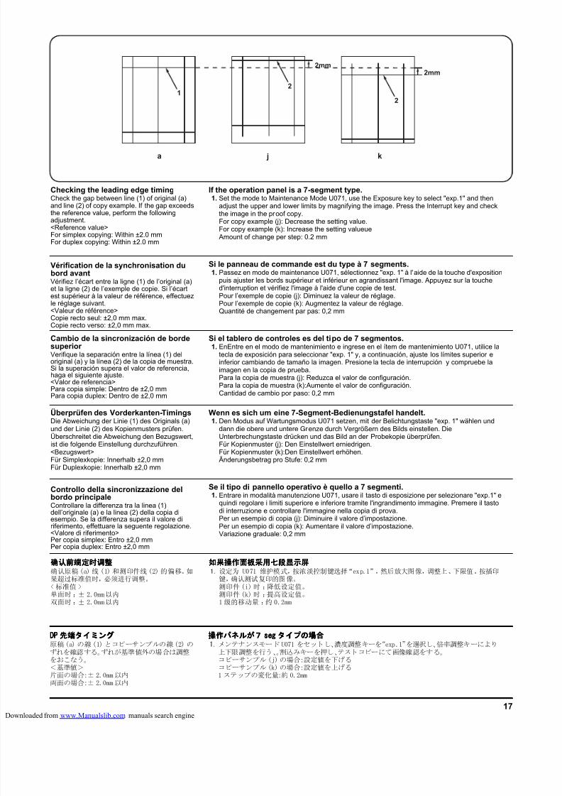
8/18/2019 taskalfa_220
http://slidepdf.com/reader/full/taskalfa220 267/30017
a
1
k
2
j
2
2mm2mm
Überprüfen des Vorderkanten-TimingsDie Abweichung der Linie (1) des Originals (a)und der Linie (2) des Kopienmusters prüfen.Überschreitet die Abweichung den Bezugswert,ist die folgende Einstellung durchzuführen.<Bezugswert>Für Simplexkopie: Innerhalb ±2,0 mmFür Duplexkopie: Innerhalb ±2,0 mm
Wenn es sich um eine 7-Segment-Bedienungstafel handelt.1. Den Modus auf Wartungsmodus U071 setzen, mit der Belichtungstaste "exp. 1" wählen und
dann die obere und untere Grenze durch Vergrößern des Bilds einstellen. DieUnterbrechungstaste drücken und das Bild an der Probekopie überprüfen.Für Kopienmuster (j): Den Einstellwert erniedrigen.Für Kopienmuster (k):Den Einstellwert erhöhen.Änderungsbetrag pro Stufe: 0,2 mm
Cambio de la sincronización de bordesuperior Verifique la separación entre la línea (1) deloriginal (a) y la línea (2) de la copia de muestra.Si la superación supera el valor de referencia,haga el siguiente ajuste.<Valor de referencia>Para copia simple: Dentro de ±2,0 mmPara copia duplex: Dentro de ±2,0 mm
Si el tablero de controles es del tipo de 7 segmentos.1. EnEntre en el modo de mantenimiento e ingrese en el ítem de mantenimiento U071, utilice la
tecla de exposición para seleccionar "exp. 1" y, a continuación, ajuste los límites superior einferior cambiando de tamaño la imagen. Presione la tecla de interrupción y compruebe laimagen en la copia de prueba.Para la copia de muestra (j): Reduzca el valor de configuración.Para la copia de muestra (k):Aumente el valor de configuración.Cantidad de cambio por paso: 0,2 mm
Vérification de la synchronisation dubord avantVérifiez l’écart entre la ligne (1) de l’original (a)et la ligne (2) de l’exemple de copie. Si l’écartest supérieur à la valeur de référence, effectuezle réglage suivant.<Valeur de référence>Copie recto seul: ±2,0 mm max.Copie recto verso: ±2,0 mm max.
Si le panneau de commande est du type à 7 segments.1. Passez en mode de maintenance U071, sélectionnez "exp. 1" à l'aide de la touche d'exposition
puis ajuster les bords supérieur et inférieur en agrandissant l'image. Appuyez sur la touched'interruption et vérifiez l'image à l'aide d'une copie de test.Pour l’exemple de copie (j): Diminuez la valeur de réglage.Pour l’exemple de copie (k): Augmentez la valeur de réglage.Quantité de changement par pas: 0,2 mm
Controllo della sincronizzazione delbordo principaleControllare la differenza tra la linea (1)dell’originale (a) e la linea (2) della copia diesempio. Se la differenza supera il valore diriferimento, effettuare la seguente regolazione.<Valore di riferimento>Per copia simplex: Entro ±2,0 mmPer copia duplex: Entro ±2,0 mm
Se il tipo di pannello operativo è quello a 7 segmenti.1. Entrare in modalità manutenzione U071, usare il tasto di esposizione per selezionare "exp.1" e
quindi regolare i limiti superiore e inferiore tramite l'ingrandimento immagine. Premere il tastodi interruzione e controllare l'immagine nella copia di prova.Per un esempio di copia (j): Diminuire il valore d’impostazione.Per un esempio di copia (k): Aumentare il valore d’impostazione.Variazione graduale: 0,2 mm
确认前端定时调整确认前端定时调整确认前端定时调整确认前端定时调整确认原稿(a) 线 (1) 和测印件线(2) 的偏移。如果超过标准值时,必须进行调整。<标准值 >单面时 :± 2.0mm以内双面时 :± 2.0mm以内
如果操作面板采用七段显示屏如果操作面板采用七段显示屏如果操作面板采用七段显示屏如果操作面板采用七段显示屏1. 设定为 U071 维护模式,按浓淡控制键选择“exp.1”,然后放大图像,调整上、下限值。按插印
键,确认测试复印的图像。测印件(i)时 :降低设定值。测印件(k)时 :提高设定值。1级的移动量 :约 0.2mm
DPDPDPDP 先端先端先端先端タイミングタイミングタイミングタイミング原稿(a) の線(1) とコピーサンプルの線(2) のずれを確認する。ずれが基準値外の場合は調整をおこなう。<基準値>片面の場合:± 2.0mm以内両面の場合:± 2.0mm以内
操作操作操作操作パネルパネルパネルパネルがががが7777 segsegsegseg タイプタイプタイプタイプのののの場合場合場合場合1. メンテナンスモード U071 をセットし、濃度調整キーを“exp.1”を選択し、倍率調整キーにより
上下限調整を行う、。割込みキーを押し、テストコピーにて画像確認をする。コピーサンプル(j)の場合:設定値を下げるコピーサンプル(k)の場合:設定値を上げる1 ステップの変化量:約 0.2mm
Checking the leading edge timingCheck the gap between line (1) of original (a)and line (2) of copy example. If the gap exceedsthe reference value, perform the followingadjustment.<Reference value>For simplex copying: Within ±2.0 mmFor duplex copying: Within ±2.0 mm
If the operation panel is a 7-segment type.1. Set the mode to Maintenance Mode U071, use the Exposure key to select "exp.1" and then
adjust the upper and lower limits by magnifying the image. Press the Interrupt key and checkthe image in the proof copy.For copy example (j): Decrease the setting value.For copy example (k): Increase the setting valueueAmount of change per step: 0.2 mm
loaded from www.Manualslib.com manuals search engine
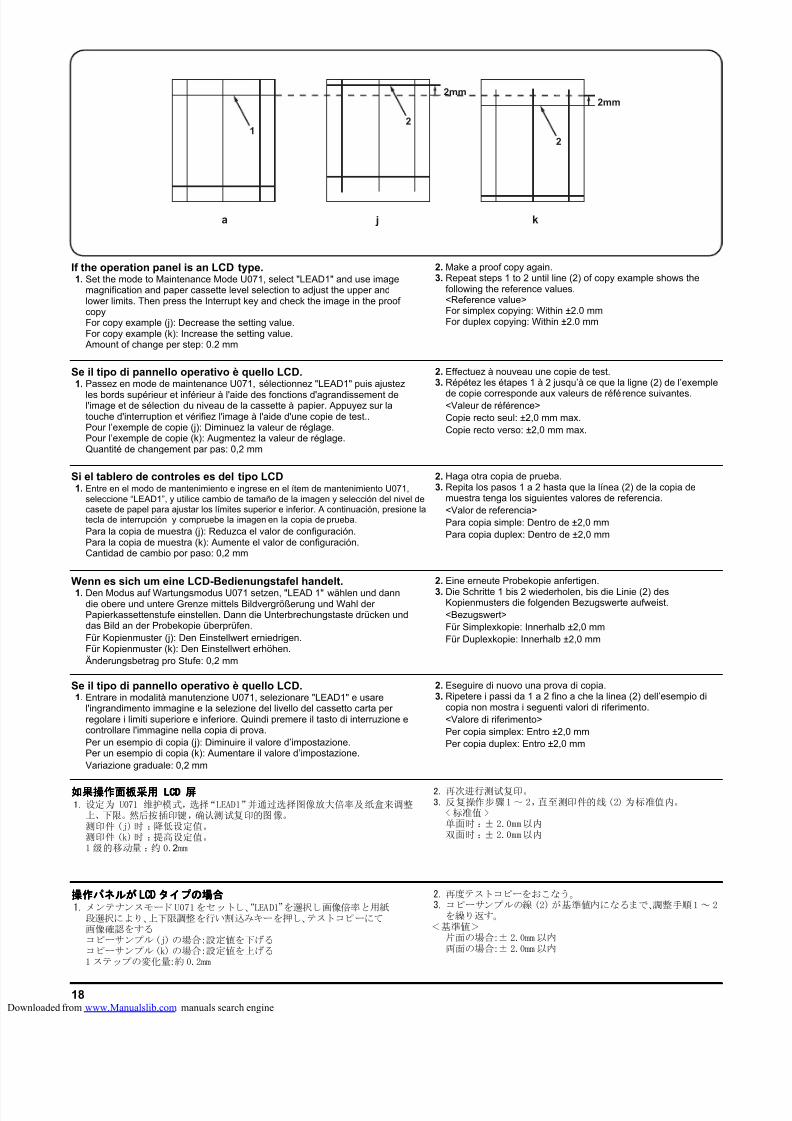
8/18/2019 taskalfa_220
http://slidepdf.com/reader/full/taskalfa220 268/30018
a
1
k
2
j
2
2mm2mm
Wenn es sich um eine LCD-Bedienungstafel handelt.1. Den Modus auf Wartungsmodus U071 setzen, "LEAD 1" wählen und dann
die obere und untere Grenze mittels Bildvergrößerung und Wahl derPapierkassettenstufe einstellen. Dann die Unterbrechungstaste drücken unddas Bild an der Probekopie überprüfen.Für Kopienmuster (j): Den Einstellwert erniedrigen.Für Kopienmuster (k): Den Einstellwert erhöhen.Änderungsbetrag pro Stufe: 0,2 mm
2. Eine erneute Probekopie anfertigen.
3. Die Schritte 1 bis 2 wiederholen, bis die Linie (2) desKopienmusters die folgenden Bezugswerte aufweist.<Bezugswert>Für Simplexkopie: Innerhalb ±2,0 mmFür Duplexkopie: Innerhalb ±2,0 mm
Si el tablero de controles es del tipo LCD1. Entre en el modo de mantenimiento e ingrese en el ítem de mantenimiento U071,
seleccione “LEAD1”, y utilice cambio de tamaño de la imagen y selección del nivel decasete de papel para ajustar los límites superior e inferior. A continuación, presione latecla de interrupción y compruebe la imagen en la copia de prueba.Para la copia de muestra (j): Reduzca el valor de configuración.Para la copia de muestra (k): Aumente el valor de configuración.Cantidad de cambio por paso: 0,2 mm
2. Haga otra copia de prueba.3. Repita los pasos 1 a 2 hasta que la línea (2) de la copia de
muestra tenga los siguientes valores de referencia.<Valor de referencia>Para copia simple: Dentro de ±2,0 mmPara copia duplex: Dentro de ±2,0 mm
Se il tipo di pannello operativo è quello LCD.1. Passez en mode de maintenance U071, sélectionnez "LEAD1" puis ajustez
les bords supérieur et inférieur à l'aide des fonctions d'agrandissement del'image et de sélection du niveau de la cassette à papier. Appuyez sur latouche d'interruption et vérifiez l'image à l'aide d'une copie de test..Pour l’exemple de copie (j): Diminuez la valeur de réglage.Pour l’exemple de copie (k): Augmentez la valeur de réglage.Quantité de changement par pas: 0,2 mm
2. Effectuez à nouveau une copie de test.3. Répétez les étapes 1 à 2 jusqu’à ce que la ligne (2) de l’exemple
de copie corresponde aux valeurs de référence suivantes.<Valeur de référence>Copie recto seul: ±2,0 mm max.Copie recto verso: ±2,0 mm max.
Se il tipo di pannello operativo è quello LCD.1. Entrare in modalità manutenzione U071, selezionare "LEAD1" e usare
l'ingrandimento immagine e la selezione del livello del cassetto carta perregolare i limiti superiore e inferiore. Quindi premere il tasto di interruzione econtrollare l'immagine nella copia di prova.Per un esempio di copia (j): Diminuire il valore d’impostazione.Per un esempio di copia (k): Aumentare il valore d’impostazione.Variazione graduale: 0,2 mm
2. Eseguire di nuovo una prova di copia.3. Ripetere i passi da 1 a 2 fino a che la linea (2) dell’esempio di
copia non mostra i seguenti valori di riferimento.<Valore di riferimento>Per copia simplex: Entro ±2,0 mmPer copia duplex: Entro ±2,0 mm
如果操作面板采用如果操作面板采用如果操作面板采用如果操作面板采用 LCDLCDLCDLCD 屏屏屏屏1. 设定为 U071 维护模式,选择“LEAD1”并通过选择图像放大倍率及纸盒来调整
上、下限。然后按插印键,确认测试复印的图像。测印件 (j)时 :降低设定值。测印件 (k)时 :提高设定值。1 级的移动量 :约 0.2mm
2. 再次进行测试复印。3. 反复操作步骤1 ~ 2,直至测印件的线(2) 为标准值内。
< 标准值 >单面时 :± 2.0mm以内双面时 :± 2.0mm以内
操作操作操作操作パネルパネルパネルパネルがががが LCLCLCLCDDDD タイプタイプタイプタイプのののの場合場合場合場合1. メンテナンスモード U071をセットし、“LEAD1”を選択し画像倍率と用紙
段選択により、上下限調整を行い割込みキーを押し、テストコピーにて画像確認をするコピーサンプル(j) の場合:設定値を下げるコピーサンプル(k) の場合:設定値を上げる1 ステップの変化量:約 0.2mm
2. 再度テストコピーをおこなう。3. コピーサンプルの線 (2)が基準値内になるまで、調整手順1 ~ 2
を繰り返す。<基準値>
片面の場合:± 2.0mm 以内両面の場合:± 2.0mm 以内
If the operation panel is an LCD type.1. Set the mode to Maintenance Mode U071, select "LEAD1" and use image
magnification and paper cassette level selection to adjust the upper andlower limits. Then press the Interrupt key and check the image in the proofcopyFor copy example (j): Decrease the setting value.For copy example (k): Increase the setting value.Amount of change per step: 0.2 mm
2. Make a proof copy again.3. Repeat steps 1 to 2 until line (2) of copy example shows the
following the reference values.<Reference value>For simplex copying: Within ±2.0 mmFor duplex copying: Within ±2.0 mm
loaded from www.Manualslib.com manuals search engine
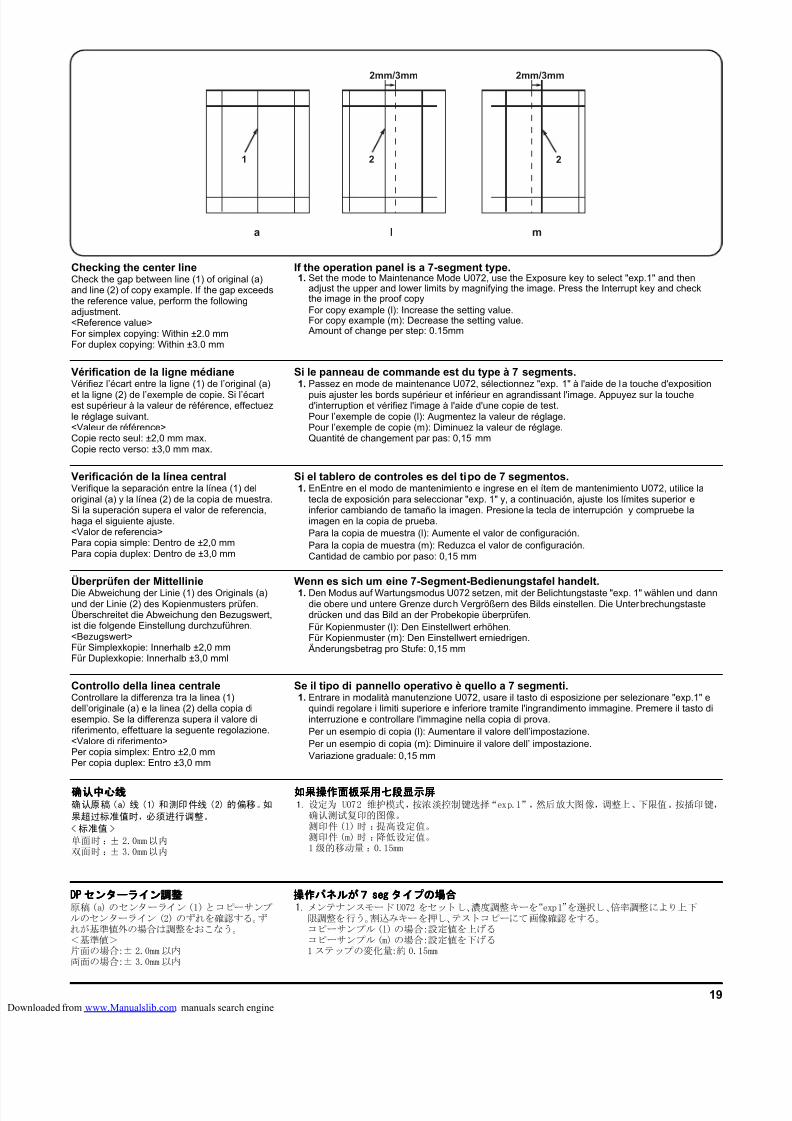
8/18/2019 taskalfa_220
http://slidepdf.com/reader/full/taskalfa220 269/30019
a ml
2mm/3mm
221
2mm/3mm
Überprüfen der MittellinieDie Abweichung der Linie (1) des Originals (a)und der Linie (2) des Kopienmusters prüfen.Überschreitet die Abweichung den Bezugswert,ist die folgende Einstellung durchzuführen.<Bezugswert>Für Simplexkopie: Innerhalb ±2,0 mmFür Duplexkopie: Innerhalb ±3,0 mml
Wenn es sich um eine 7-Segment-Bedienungstafel handelt.1. Den Modus auf Wartungsmodus U072 setzen, mit der Belichtungstaste "exp. 1" wählen und dann
die obere und untere Grenze durch Vergrößern des Bilds einstellen. Die Unterbrechungstastedrücken und das Bild an der Probekopie überprüfen.Für Kopienmuster (l): Den Einstellwert erhöhen.Für Kopienmuster (m): Den Einstellwert erniedrigen.Änderungsbetrag pro Stufe: 0,15 mm
Verificación de la línea centralVerifique la separación entre la línea (1) deloriginal (a) y la línea (2) de la copia de muestra.Si la superación supera el valor de referencia,haga el siguiente ajuste.<Valor de referencia>Para copia simple: Dentro de ±2,0 mmPara copia duplex: Dentro de ±3,0 mm
Si el tablero de controles es del tipo de 7 segmentos.1. EnEntre en el modo de mantenimiento e ingrese en el ítem de mantenimiento U072, utilice la
tecla de exposición para seleccionar "exp. 1" y, a continuación, ajuste los límites superior einferior cambiando de tamaño la imagen. Presione la tecla de interrupción y compruebe laimagen en la copia de prueba.Para la copia de muestra (l): Aumente el valor de configuración.Para la copia de muestra (m): Reduzca el valor de configuración.Cantidad de cambio por paso: 0,15 mm
Vérification de la ligne médianeVérifiez l’écart entre la ligne (1) de l’original (a)
et la ligne (2) de l’exemple de copie. Si l’écartest supérieur à la valeur de référence, effectuezle réglage suivant.<Valeur de référence>Copie recto seul: ±2,0 mm max.Copie recto verso: ±3,0 mm max.
Si le panneau de commande est du type à 7 segments.1. Passez en mode de maintenance U072, sélectionnez "exp. 1" à l'aide de la touche d'exposition
puis ajuster les bords supérieur et inférieur en agrandissant l'image. Appuyez sur la touched'interruption et vérifiez l'image à l'aide d'une copie de test.Pour l’exemple de copie (l): Augmentez la valeur de réglage.Pour l’exemple de copie (m): Diminuez la valeur de réglage.Quantité de changement par pas: 0,15 mm
Controllo della linea centraleControllare la differenza tra la linea (1)dell’originale (a) e la linea (2) della copia diesempio. Se la differenza supera il valore diriferimento, effettuare la seguente regolazione.<Valore di riferimento>Per copia simplex: Entro ±2,0 mmPer copia duplex: Entro ±3,0 mm
Se il tipo di pannello operativo è quello a 7 segmenti.1. Entrare in modalità manutenzione U072, usare il tasto di esposizione per selezionare "exp.1" e
quindi regolare i limiti superiore e inferiore tramite l'ingrandimento immagine. Premere il tasto diinterruzione e controllare l'immagine nella copia di prova.Per un esempio di copia (l): Aumentare il valore dell’impostazione.Per un esempio di copia (m): Diminuire il valore dell’ impostazione.Variazione graduale: 0,15 mm
确认中心线确认中心线确认中心线确认中心线确认原稿(a) 线 (1) 和测印件线 (2) 的偏移。如
果超过标准值时,必须进行调整。
<标准值 >
单面时 :± 2.0mm以内双面时 :± 3.0mm以内
如果操作面板采用七段显示屏如果操作面板采用七段显示屏如果操作面板采用七段显示屏如果操作面板采用七段显示屏1. 设定为 U072 维护模式,按浓淡控制键选择“exp.1”,然后放大图像,调整上、下限值。按插印键,
确认测试复印的图像。测印件(l)时 :提高设定值。测印件(m)时 :降低设定值。1级的移动量 :0.15mm
DPDPDPDP センターラインセンターラインセンターラインセンターライン調整調整調整調整原稿(a) のセンターライン(1)とコピーサンプルのセンターライン (2) のずれを確認する。ずれが基準値外の場合は調整をおこなう。<基準値>片面の場合:± 2.0mm以内両面の場合:± 3.0mm以内
操作操作操作操作パネルパネルパネルパネルがががが7777 segsegsegseg タイプタイプタイプタイプのののの場合場合場合場合1. メンテナンスモード U072 をセットし、濃度調整キーを“exp1”を選択し、倍率調整により上下
限調整を行う。割込みキーを押し、テストコピーにて画像確認をする。コピーサンプル(l)の場合:設定値を上げるコピーサンプル(m)の場合:設定値を下げる1 ステップの変化量:約 0.15mm
Checking the center lineCheck the gap between line (1) of original (a)and line (2) of copy example. If the gap exceedsthe reference value, perform the followingadjustment.<Reference value>For simplex copying: Within ±2.0 mmFor duplex copying: Within ±3.0 mm
If the operation panel is a 7-segment type.1. Set the mode to Maintenance Mode U072, use the Exposure key to select "exp.1" and then
adjust the upper and lower limits by magnifying the image. Press the Interrupt key and checkthe image in the proof copyFor copy example (l): Increase the setting value.For copy example (m): Decrease the setting value.Amount of change per step: 0.15mm
loaded from www.Manualslib.com manuals search engine
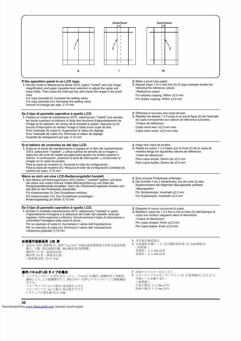
8/18/2019 taskalfa_220
http://slidepdf.com/reader/full/taskalfa220 270/30020
a ml
2mm/3mm
221
2mm/3mm
Wenn es sich um eine LCD-Bedienungstafel handelt.1. Den Modus auf Wartungsmodus U072 setzen, "1saided" wählen und dann
die obere und untere Grenze mittels Bildvergrößerung und Wahl derPapierkassettenstufe einstellen. Dann die Unterbrechungstaste drücken unddas Bild an der Probekopie überprüfen.Für Kopienmuster (l): Den Einstellwert erhöhen.Für Kopienmuster (m): Den Einstellwert erniedrigen.Änderungsbetrag pro Stufe: 0,15 mm
2. Eine erneute Probekopie anfertigen.3. Die Schritte 1 bis 2 wiederholen, bis die Linie (2) desKopienmusters die folgenden Bezugswerte aufweist.<Bezugswert>Für Simplexkopie: Innerhalb ±2,0 mmFür Duplexkopie: Innerhalb ±3,0 mm
Si el tablero de controles es del tipo LCD.1. Entre en el modo de mantenimiento e ingrese en el ítem de mantenimiento
U072, seleccione “1saided”, y utilice cambio de tamaño de la imagen yselección del nivel de casete de papel para ajustar los límites superior einferior. A continuación, presione la tecla de interrupción y compruebe laimagen en la copia de prueba.Para la copia de muestra (l): Aumente el valor de configuración.Para la copia de muestra (m): Reduzca el valor de configuración.Cantidad decambio por paso: 0,15 mm
2. Haga otra copia de prueba.3. Repita los pasos 1 a 2 hasta que la línea (2) de la copia de
muestra tenga los siguientes valores de referencia.<Valor de referencia>Para copia simple: Dentro de ±2,0 mmPara copia duplex: Dentro de ±3,0 mm
Se il tipo di pannello operativo è quello LCD.1. Passez en mode de maintenance U072, sélectionnez "1sided" puis ajustez
les bords supérieur et inférieur à l'aide des fonctions d'agrandissement del'image et de sélection du niveau de la cassette à papier. Appuyez sur latouche d'interruption et vérifiez l'image à l'aide d'une copie de test.Pour l’exemple de copie (l): Augmentez la valeur de réglage.Pour l’exemple de copie (m): Diminuez la valeur de réglage.Quantité de changement par pas: 0,15 mm
2. Effectuez à nouveau une copie de test.3. Répétez les étapes 1 à 2 jusqu’à ce que la ligne (2) de l’exemple
de copie corresponde aux valeurs de référence suivantes.<Valeur de référence>Copie recto seul: ±2,0 mm max.Copie recto verso: ±3,0 mm max.
Se il tipo di pannello operativo è quello LCD.1. Entrare in modalità manutenzione U072, selezionare "1saided" e usare
l'ingrandimento immagine e la selezione del livello del cassetto carta perregolare i limiti superiore e inferiore. Quindi premere il tasto di interruzione econtrollare l'immagine nella copia di prova.Per un esempio di copia (l): Aumentare il valore dell’impostazione.Per un esempio di copia (m): Diminuire il valore dell’ impostazione.Variazione graduale: 0,15 mm
2. Eseguire di nuovo una prova di copia.3. Ripetere i passi da 1 a 2 fino a che la linea (2) dell’esempio di
copia non mostra i seguenti valori di riferimento.<Valore di riferimento>Per copia simplex: Entro ±2,0 mmPer copia duplex: Entro ±3,0 mm
如果操作面板采用如果操作面板采用如果操作面板采用如果操作面板采用 LCDLCDLCDLCD 屏屏屏屏1. 设定为 U072 维护模式,选择“1saided”并通过选择图像放大倍率及纸盒来调
整上、下限。然后按插印键,确认测试复印的图像。测印件 (l)时 :提高设定值。测印件 (m)时 :降低设定值。1 级的移动量 :约 0.15mm
2. 再次进行测试复印。3. 反复操作步骤1 ~ 2,直至测印件的线(2) 为标准值内。
< 标准值 >单面时 :± 2.0mm以内双面时 :± 3.0mm以内
操作操作操作操作パネルパネルパネルパネルがががが LCLCLCLCDDDD タイプタイプタイプタイプのののの場合場合場合場合1. メンテナンスモード U072 をセットし、“1sided”を選択し画像倍率と用紙段
選択により、上下限調整を行う。割込みキーを押しテストコピーにて画像確認をする。コピーサンプル(l) の場合:設定値を上げるコピーサンプル(m) の場合:設定値を下げる1 ステップの変化量:約 0.15mm
2. 再度テストコピーをおこなう。3. コピーサンプルのセンターライン(2) が基準値内になるまで、
手順1 ~ 2 を繰り返す。<基準値>片面の場合:± 2.0mm 以内両面の場合:± 3.0mm 以内
If the operation panel is an LCD type.1. Set the mode to Maintenance Mode U072, select "1sided" and use image
magnification and paper cassette level selection to adjust the upper andlower limits. Then press the Interrupt key and check the image in the proofcopyFor copy example (l): Increase the setting value.For copy example (m): Decrease the setting value.Amount of change per step: 0.15 mm
2. Make a proof copy again.3. Repeat steps 1 to 2 until line (2) of copy example shows the
following the reference values.<Reference value>For simplex copying: Within ±2.0 mmFor duplex copying: Within ±3.0 mm
loaded from www.Manualslib.com manuals search engine
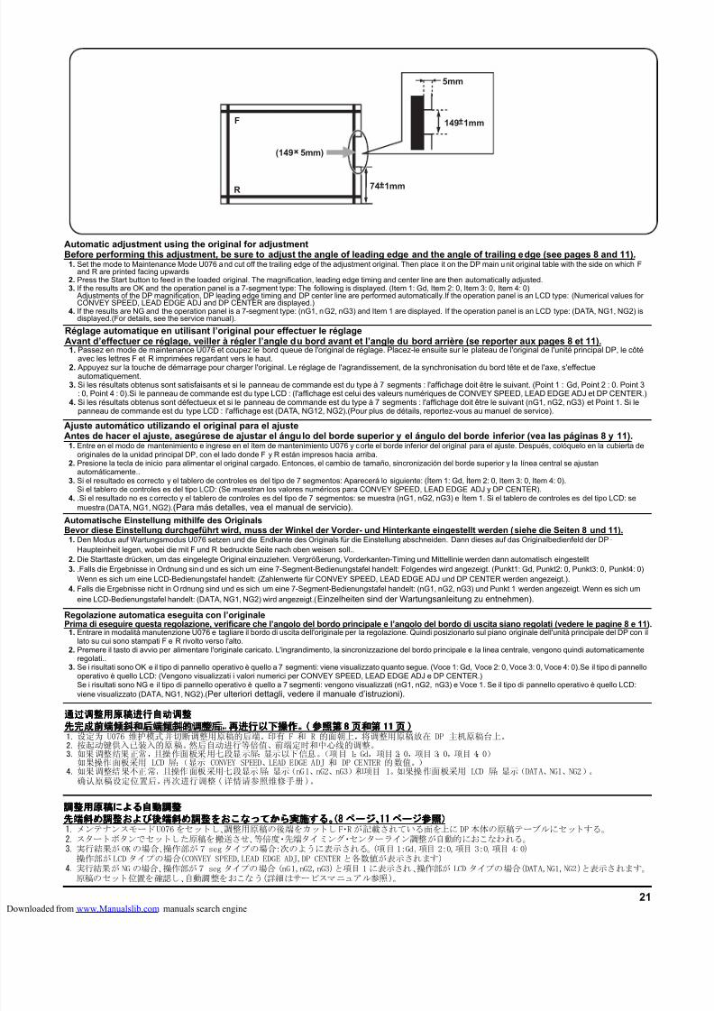
8/18/2019 taskalfa_220
http://slidepdf.com/reader/full/taskalfa220 271/30021
F
R
5mm
(149 5mm)
74 1mm
149 1mm
Automatische Einstellung mithilfe des Originals
Bevor diese Einstellung durchgeführt wird, muss der Winkel der Vorder- und Hinterkante eingestellt werden (siehe die Seiten 8 und 11).1. Den Modus auf Wartungsmodus U076 setzen und die Endkante des Originals für die Einstellung abschneiden. Dann dieses auf das Originalbedienfeld der DP-Haupteinheit legen, wobei die mit F und R bedruckte Seite nach oben weisen soll..
2. Die Starttaste drücken, um das eingelegte Original einzuziehen. Vergrößerung, Vorderkanten-Timing und Mittellinie werden dann automatisch eingestellt3. .Falls die Ergebnisse in Ordnung sind und es sich um eine 7-Segment-Bedienungstafel handelt: Folgendes wird angezeigt. (Punkt1: Gd, Punkt2: 0, Punkt3: 0, Punkt4: 0)
Wenn es sich um eine LCD-Bedienungstafel handelt: (Zahlenwerte für CONVEY SPEED, LEAD EDGE ADJ und DP CENTER werden angezeigt.).4. Falls die Ergebnisse nicht in Ordnung sind und es sich um eine 7-Segment-Bedienungstafel handelt: (nG1, nG2, nG3) und Punkt 1 werden angezeigt. Wenn es sich um
eine LCD-Bedienungstafel handelt: (DATA, NG1, NG2) wird angezeigt.(Einzelheiten sind der Wartungsanleitung zu entnehmen).
Ajuste automático utilizando el original para el ajusteAntes de hacer el ajuste, asegúrese de ajustar el ángulo del borde superior y el ángulo del borde inferior (vea las páginas 8 y 11).
1. Entre en el modo de mantenimiento e ingrese en el ítem de mantenimiento U076 y corte el borde inferior del original para el ajuste. Después, colóquelo en la cubierta deoriginales de la unidad principal DP, con el lado donde F y R están impresos hacia arriba.
2. Presione la tecla de inicio para alimentar el original cargado. Entonces, el cambio de tamaño, sincronización del borde superior y la línea central se ajustanautomáticamente..
3. Si el resultado es correcto y el tablero de controles es del tipo de 7 segmentos: Aparecerá lo siguiente: (Ítem 1: Gd, Ítem 2: 0, Item 3: 0, Item 4: 0).Si el tablero de controles es del tipo LCD: (Se muestran los valores numéricos para CONVEY SPEED, LEAD EDGE ADJ y DP CENTER).
4. .Si el resultado no es correcto y el tablero de controles es del tipo de 7 segmentos: se muestra (nG1, nG2, nG3) e Ítem 1. Si el tablero de controles es del tipo LCD: semuestra (DATA, NG1, NG2).(Para más detalles, vea el manual de servicio).
Réglage automatique en utilisant l’original pour effectuer le réglageAvant d’effectuer ce réglage, veiller à régler l’angle du bord avant et l’angle du bord arrière (se reporter aux pages 8 et 11).
1.Passez en mode de maintenance U076 et coupez le bord queue de l'original de réglage. Placez-le ensuite sur le plateau de l'original de l'unité principal DP, le côtéavec les lettres F et R imprimées regardant vers le haut.
2. Appuyez sur la touche de démarrage pour charger l'original. Le réglage de l'agrandissement, de la synchronisation du bord tête et de l'axe, s'effectueautomatiquement.
3. Si les résultats obtenus sont satisfaisants et si le panneau de commande est du type à 7 segments : l'affichage doit être le suivant. (Point 1 : Gd, Point 2 : 0. Point 3: 0, Point 4 : 0).Si le panneau de commande est du type LCD : (l'affichage est celui des valeurs numériques de CONVEY SPEED, LEAD EDGE ADJ et DP CENTER.)
4. Si les résultats obtenus sont défectueux et si le panneau de commande est du type à 7 segments : l'affichage doit être le suivant (nG1, nG2, nG3) et Point 1. Si lepanneau de commande est du type LCD : l'affichage est (DATA, NG12, NG2).(Pour plus de détails, reportez-vous au manuel de service).
Regolazione automatica eseguita con l’originalePrima di eseguire questa regolazione, verificare che l’angolo del bordo principale e l’angolo del bordo di uscita siano regolati (vedere le pagine 8 e 11).
1. Entrare in modalità manutenzione U076 e tagliare il bordo di uscita dell'originale per la regolazione. Quindi posizionarlo sul piano originale dell'unità principale del DP con illato su cui sono stampati F e R rivolto verso l'alto.
2. Premere il tasto di avvio per alimentare l'originale caricato. L'ingrandimento, la sincronizzazione del bordo principale e la linea centrale, vengono quindi automaticamenteregolati..
3. Se i risultati sono OK e il tipo di pannello operativo è quello a 7 segmenti: viene visualizzato quanto segue. (Voce 1: Gd, Voce 2: 0, Voce 3: 0, Voce 4: 0).Se il tipo di pannellooperativo è quello LCD: (Vengono visualizzati i valori numerici per CONVEY SPEED, LEAD EDGE ADJ e DP CENTER.)Se i risultati sono NG e il tipo di pannello operativo è quello a 7 segmenti: vengono visualizzati (nG1, nG2, nG3) e Voce 1. Se il tipo di pannello operativo è quello LCD:viene visualizzato (DATA, NG1, NG2).(Per ulteriori dettagli, vedere il manuale d’istruzioni).
通过调整用原稿进行自动调整通过调整用原稿进行自动调整通过调整用原稿进行自动调整通过调整用原稿进行自动调整
先完成前端倾斜和后端倾斜的调整后先完成前端倾斜和后端倾斜的调整后先完成前端倾斜和后端倾斜的调整后先完成前端倾斜和后端倾斜的调整后,,,,再进行以下操作再进行以下操作再进行以下操作再进行以下操作。。。。(((( 参照第参照第参照第参照第 8888 页和第页和第页和第页和第 11111111 页页页页 ))))1. 设定为 U076 维护模式并切断调整用原稿的后端。印有 F 和 R 的面朝上,将调整用原稿放在 DP 主机原稿台上。2. 按起动键供入已装入的原稿。然后自动进行等倍值、前端定时和中心线的调整。3. 如果调整结果正常,且操作面板采用七段显示屏:显示以下信息。(项目 1:Gd,项目 2:0,项目 3:0,项目 4:0)
如果操作面板采用 LCD 屏:(显示 CONVEY SPEED、LEAD EDGE ADJ 和 DP CENTER 的数值。)4. 如果调整结果不正常,且操作面板采用七段显示屏:显示(nG1、nG2、nG3)和项目 1。如果操作面板采用 LCD 屏:显示(DATA、NG1、NG2)。
确认原稿设定位置后,再次进行调整(详情请参照维修手册)。
調整用原稿調整用原稿調整用原稿調整用原稿によるによるによるによる自動調整自動調整自動調整自動調整先端斜先端斜先端斜先端斜めめめめ調整調整調整調整およびおよびおよびおよび後端斜後端斜後端斜後端斜めめめめ調整調整調整調整をおこなってからをおこなってからをおこなってからをおこなってから実施実施実施実施するするするする。(。(。(。(8888 ページページページページ、、、、11111111 ページページページページ参照参照参照参照))))1. メンテナンスモードU076をセットし、調整用原稿の後端をカットし F・R が記載されている面を上に DP本体の原稿テーブルにセットする。2. スタートボタンでセットした原稿を搬送させ、等倍度・先端タイミング・センターライン調整が自動的におこなわれる。3. 実行結果がOKの場合、操作部が7seg タイプの場合:次のように表示される。(項目 1:Gd,項目 2:0,項目 3:0,項目 4:0)
操作部がLCD タイプの場合(CONVEY SPEED,LEAD EDGE ADJ,DP CENTER と各数値が表示されます)4. 実行結果が NG の場合、操作部が7 seg タイプの場合 (nG1,nG2,nG3)と項目 1 に表示され、操作部が LCD タイプの場合(DATA,NG1,NG2)と表示されます。
原稿のセット位置を確認し、自動調整をおこなう(詳細はサービスマニュアル参照)。
Automatic adjustment using the original for adjustmentBefore performing this adjustment, be sure to adjust the angle of leading edge and the angle of trailing edge (see pages 8 and 11).
1. Set the mode to Maintenance Mode U076 and cut off the trailing edge of the adjustment original. Then place it on the DP main unit original table with the side on which Fand R are printed facing upwards
2. Press the Start button to feed in the loaded original. The magnification, leading edge timing and center line are then automatically adjusted.3. If the results are OK and the operation panel is a 7-segment type: The following is displayed. (Item 1: Gd, Item 2: 0, Item 3: 0, Item 4: 0)
Adjustments of the DP magnification, DP leading edge timing and DP center line are performed automatically.If the operation panel is an LCD type: (Numerical values forCONVEY SPEED, LEAD EDGE ADJ and DP CENTER are displayed.)
4. If the results are NG and the operation panel is a 7-segment type: (nG1, nG2, nG3) and Item 1 are displayed. If the operation panel is an LCD type: (DATA, NG1, NG2) isdisplayed.(For details, see the service manual).
loaded from www.Manualslib.com manuals search engine
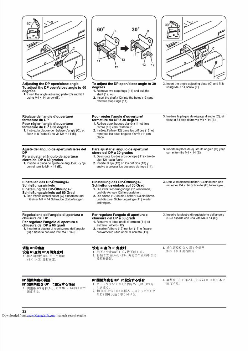
8/18/2019 taskalfa_220
http://slidepdf.com/reader/full/taskalfa220 272/30022
C
E11 13
1312
C
11
12
C
C
E
Einstellen des DP-Öffnungs-/SchließungswinkelsEinstellung des DP-Öffnungs-/Schließungswinkels auf 60 Grad1. Den Winkeleinstellhalter (C) einsetzen und
mit einer M4 × 14 Schraube (E) befestigen.
Einstellung des DP-Öffnungs-/Schließungswinkels auf 30 Grad1. Die zwei Sicherungsringe (11) entfernen,
und die Achse (12) herausziehen.2. Die Achse (12) in die Löcher (13) einführen,
und die zwei Sicherungsringe (11) wiederanbringen.
3. Den Winkeleinstellhalter (C) einsetzen und
mit einer M4 × 14 Schraube (E) befestigen.
Ajuste del ángulo de apertura/cierre delDPPara ajustar el ángulo de apertura/cierre del DP a 60 grados1. Inserte la placa de ajuste de ángulo (C) y fije
con el tornillo M4 × 14 (E).
Para ajustar el ángulo de apertura/cierre del DP a 30 grados1. Desmonte los dos aros de tope (11) y tire del
eje (12) hacia fuera.2. Inserte el eje (12) en los orificios (13) y
vuelva a colocar los dos aros de tope (11).
3. Inserte la placa de ajuste de ángulo (C) y fijecon el tornillo M4 × 14 (E).
Réglage de l’angle d’ouverture/fermeture du DP
Pour régler l’angle d’ouverture/fermeture du DP à 60 degrés1. Insérez la plaque de réglage d’angle (C), et
fixez-la à l’aide d’une vis M4 × 14 (E).
Pour régler l’angle d’ouverture/fermeture du DP à 30 degrés1. Retirez deux bagues d’arrêt (11) et tirez
l’arbre (12) vers l’extérieur.2. Insérez l’arbre (12) dans les orifices (13) et
remettez les deux bagues d’arrêt (11) enplace.
3. Insérez la plaque de réglage d’angle (C), etfixez-la à l’aide d’une vis M4 × 14 (E).
Regolazione dell’angolo di apertura echiusura del DPPer regolare l’angolo di apertura echiusura del DP a 60 gradi1. Inserire la piastra di regolazione dell’angolo
(C) e fissarla con una vite M4 × 14 (E).
Per regolare l’angolo di apertura echiusura del DP a 30 gradi1. Rimuovere i due anelli di arresto (11) ed
estrarre l’albero (12).2. Inserire l’albero (12) nei fori (13) e fissare
nuovamente i due anelli di arresto (11).
3. Inserire la piastra di regolazione dell’angolo(C) e fissarla con una vite M4 × 14 (E).
调整调整调整调整 DPDPDPDP的角度的角度的角度的角度
设定设定设定设定 60606060 度的度的度的度的 DPDPDPDP 开闭角度时开闭角度时开闭角度时开闭角度时1. 插入调整板 (C),用 1 个螺丝
M4× 14(E) 进行固定。
设定设定设定设定 30303030度的度的度的度的DPDPDPDP角度时角度时角度时角度时1. 拆下 2个止动环(11),拔下轴(12)。2. 将轴(12)插入孔 (13),并将2个止动环 (11)
按原样装好。
3. 插入调整板 (C),用 1个螺丝M4× 14(E) 进行固定。
DPDPDPDP 開閉角度開閉角度開閉角度開閉角度のののの調整調整調整調整DPDPDPDP 開閉角度開閉角度開閉角度開閉角度をををを 60606060°°°°にににに設定設定設定設定するするするする場合場合場合場合1. 調整板(C)を挿入し、ビスM4× 14(E)1本で
固定する。
DPDPDPDP 開閉角度開閉角度開閉角度開閉角度をををを 30303030°°°°にににに設定設定設定設定するするするする場合場合場合場合1. ストップリング(11)2 個を外し、軸 (12)を
引き抜く。2. 軸 (12)を穴(13)に挿入し、ストップリング
(11)2個を元通り取り付ける。
3. 調整板(C)を挿入し、ビスM4× 14(E)1本で固定する。
Adjusting the DP open/close angleTo adjust the DP open/close angle to 60degrees1. Insert the angle adjusting plate (C) and fit it
using M4 × 14 screw (E).
To adjust the DP open/close angle to 30degrees1. Remove two stop rings (11) and pull the
shaft (12) out.2. Insert the shaft (12) into the holes (13) and
refit two stop r ings (11).
3. Insert the angle adjusting plate (C) and fit itusing M4 × 14 screw (E).
loaded from www.Manualslib.com manuals search engine

8/18/2019 taskalfa_220
http://slidepdf.com/reader/full/taskalfa220 273/300
INSTALLATION GUIDE FOR
PAPER FEEDER
loaded from www.Manualslib.com manuals search engine
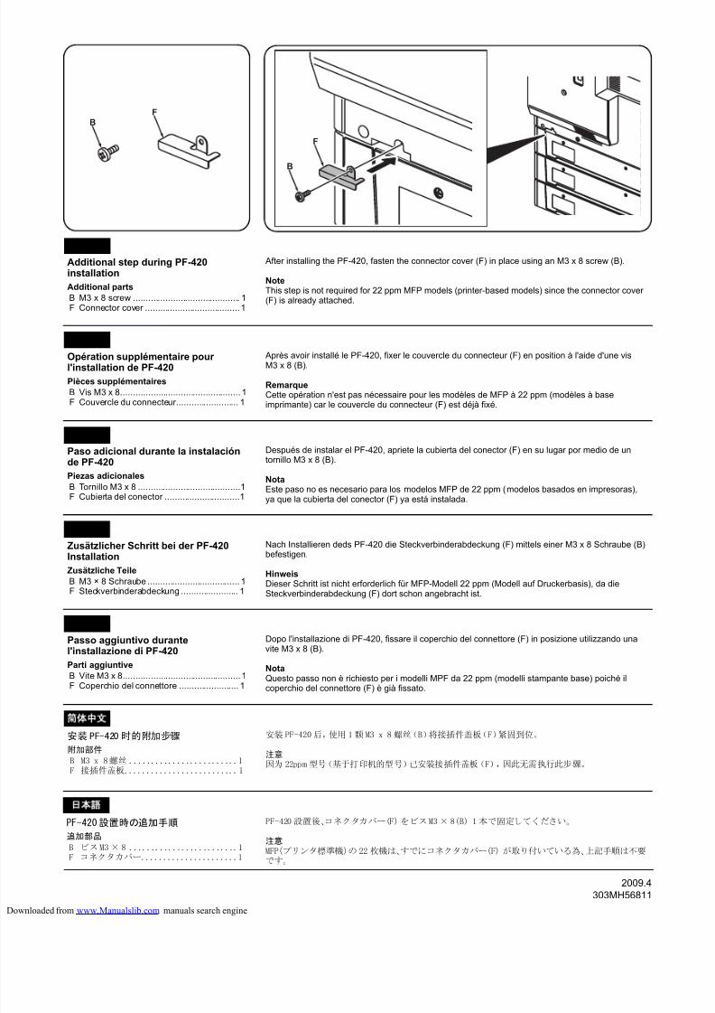
8/18/2019 taskalfa_220
http://slidepdf.com/reader/full/taskalfa220 274/300
2009.4303MH56811
F
B
F
B
Additional step during PF-420installation
Additional parts
B M3 x 8 screw ........................................... 1F Connector cover ......................................1
English
Opération supplémentaire pourl'installation de PF-420
Pièces supplémentaires
B Vis M3 x 8................................................ 1F Couvercle du connecteur......................... 1
Français
Après avoir installé le PF-420, fixer le couvercle du connecteur (F) en position à l'aide d'une visM3 x 8 (B).
RemarqueCette opération n'est pas nécessaire pour les modèles de MFP à 22 ppm (modèles à baseimprimante) car le couvercle du connecteur (F) est déjà fixé.
Paso adicional durante la instalaciónde PF-420
Piezas adicionales
B Tornillo M3 x 8 .........................................1F Cubierta del conector ..............................1
Español
Después de instalar el PF-420, apriete la cubierta del conector (F) en su lugar por medio de untornillo M3 x 8 (B).
NotaEste paso no es necesario para los modelos MFP de 22 ppm (modelos basados en impresoras),ya que la cubierta del conector (F) ya está instalada.
Zusätzlicher Schritt bei der PF-420Installation
Zusätzliche Teile
B M3 × 8 Schraube ..................................... 1F Steckverbinderabdeckung ....................... 1
Deutsch
Passo aggiuntivo durantel'installazione di PF-420
Parti aggiuntive
B Vite M3 x 8...............................................1F Coperchio del connettore ........................ 1
Italiano
PF-420設置時の追加手順
追加部品
B ビスM3× 8 .........................1F コネクタカバー......................1
語
安装PF-420 时的附加步骤
附加部件
B M3 x 8螺丝 .........................1F 接插件盖板..........................1
简 文
PF-420 設置後、コネクタカバー(F) をビスM3× 8(B) 1本で固定してください。
注意MFP(プリンタ標準機)の 22 枚機は、すでにコネクタカバー(F) が取り付いている為、上記手順は不要です。
After installing the PF-420, fasten the connector cover (F) in place using an M3 x 8 screw (B).
NoteThis step is not required for 22 ppm MFP models (printer-based models) since the connector cover(F) is already attached.
安装 PF-420后,使用 1颗 M3 x 8 螺丝(B)将接插件盖板(F)紧固到位。
注意因为 22ppm 型号(基于打印机的型号)已安装接插件盖板(F),因此无需执行此步骤。
Nach Installieren deds PF-420 die Steckverbinderabdeckung (F) mittels einer M3 x 8 Schraube (B)befestigen.
HinweisDieser Schritt ist nicht erforderlich für MFP-Modell 22 ppm (Modell auf Druckerbasis), da dieSteckverbinderabdeckung (F) dort schon angebracht ist.
Dopo l'installazione di PF-420, fissare il coperchio del connettore (F) in posizione utilizzando unavite M3 x 8 (B).
NotaQuesto passo non è richiesto per i modelli MPF da 22 ppm (modelli stampante base) poiché ilcoperchio del connettore (F) è già fissato.
loaded from www.Manualslib.com manuals search engine
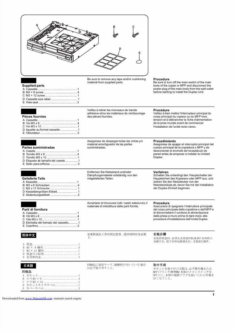
8/18/2019 taskalfa_220
http://slidepdf.com/reader/full/taskalfa220 275/3001
B
E
D
AC
Supplied parts A Cassette ..................................................1B M3 × 8 screw........................................... 4C M3 × 12 screw......................................... 1D Cassette size label .................................. 1E Hole seal..................................................3
English Be sure to remove any tape and/or cushioningmaterial from supplied parts.
ProcedureBe sure to turn off the main switch of the mainbody of the copier or MFP and disconnect thepower plug of the main body from the wall outletbefore starting to install the Duplex Unit.
Pièces fournies A Cassette ..................................................1B Vis M3 x 8................................................ 4C Vis M3 x 12.............................................. 1D tiquette au format cassette ...................... 1E Obturateur ............................................... 3
Français Veillez à retirer les morceaux de bandeadhésive et/ou les matériaux de rembourrage
des pièces fournies.
ProcédureVeillez à bien mettre l'interrupteur principal du
corps principal du copieur ou du MFP horstension et à débrancher la fiche d'alimentationde la prise murale avant de commencerl'installation de l'unité recto-verso.
Partes suministradas A Casete ..................................................... 1B Tornillo M3 x 8 .........................................4C Tornillo M3 x 12 .......................................1D Etiqueta de tamaño del casete................ 1E Sello para orificios ................................... 3
Español Asegúrese de despegar todas las cintas y/omaterial amortiguador de las partessuministradas.
Procedimiento Asegúrese de apagar el interruptor principal delcuerpo principal de la copiadora o MFP y dedesconectar el enchufe del receptáculo depared antes de empezar a instalar la UnidadDúplex.
Gelieferte Teile A Kassette...................................................1B M3 x 8 Schrauben ................................... 4C M3 x 12 Schraube ................................... 1D Kassettengrößen-Etikett..........................1E Abdeckungsetikett ................................... 3
Deutsch
Entfernen Sie Klebeband und/oder
Dämpfungsmaterial vollständig von denmitgelieferten Teilen.
VerfahrenSchalten Sie unbedingt den Hauptschalter derHaupteinheit des Kopierers oder MFP aus, undziehen Sie den Netzstecker von derNetzsteckdose ab, bevor Sie mit der Installationder Duplex-Einheit beginnen.
Parti di fornitura A Cassetto ..................................................1B Viti M3 x 8 ................................................ 4C Vite M3 x 12............................................. 1D Etichetta del formato del cassetto............ 1E Copriforo.................................................. 3
Italiano Accertarsi di rimuovere tutti i nastri adesivi e/o ilmateriale di imbottitura dalle parti fornite.
Procedura Assicurarsi di spegnere l’interruttore principaledel corpo principale della copiatrice o dell’MFP edi disconnettere il cordone di alimentazionedalla presa a muro prima di dare inizio allaprocedura d’installazione dell’Unità Duplex.
同梱品A カセット............................1B ビスM3× 8 .........................4C ビスM3× 12 ........................1D カセットサイズラベル................1E カバーラベル........................3
本語
同梱品に固定テープ、緩衝材が付いている場合は必ず取り外すこと。
取付手順カセットを取り付ける際は、必ず複写機またはMFP(プリンタ標準機)本体のメインスイッチをOFF にし、本体の電源プラグを抜いてから作業をおこなうこと。
A 纸盒................................1B M3× 8 螺丝 ........................4C M3× 12 螺丝........................1D 纸盒尺寸标签........................1E 孔用密封盖..........................3
简 文
如果附属品上带有固定胶带、缓冲材料时务必揭下。
装 骤
安装供纸盒时,必须先关闭复印机或MFP本体的主电源开关,拔下本体电源插头后,才能进行操作。
loaded from www.Manualslib.com manuals search engine
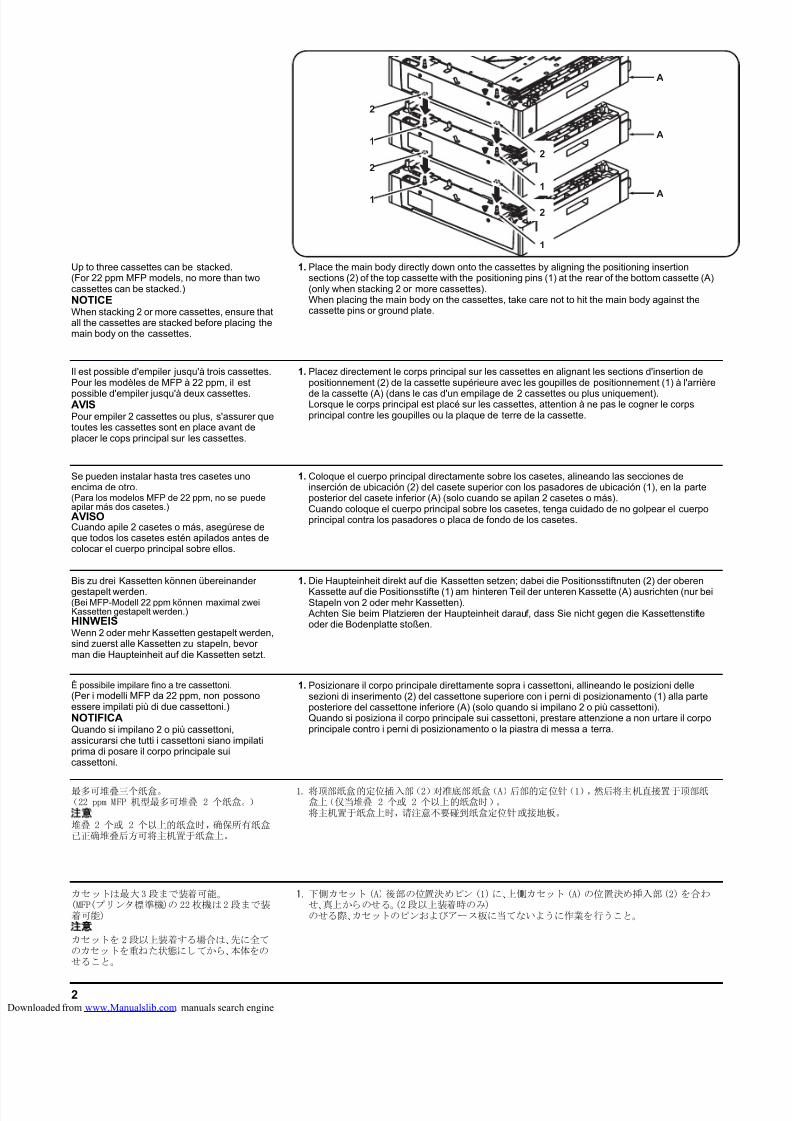
8/18/2019 taskalfa_220
http://slidepdf.com/reader/full/taskalfa220 276/3002
1.
A
A
A
1
2
1
2
1
1
2
2
カセットは最大3 段まで装着可能。(MFP(プリンタ標準機)の 22枚機は2 段まで装着可能)注
カセットを 2 段以上装着する場合は、先に全てのカセットを重ねた状態にしてから、本体をのせること。
1.下側カセット(A)後部の位置決めピン (1)に、上側カセット(A)の位置決め挿入部(2)を合わせ、真上からのせる。(2段以上装着時のみ)のせる際、カセットのピンおよびアース板に当てないように作業を行うこと。
Up to three cassettes can be stacked.(For 22 ppm MFP models, no more than twocassettes can be stacked.)NOTICEWhen stacking 2 or more cassettes, ensure thatall the cassettes are stacked before placing themain body on the cassettes.
Il est possible d'empiler jusqu'à trois cassettes.Pour les modèles de MFP à 22 ppm, il est
possible d'empiler jusqu'à deux cassettes.AVISPour empiler 2 cassettes ou plus, s'assurer quetoutes les cassettes sont en place avant deplacer le cops principal sur les cassettes.
Se pueden instalar hasta tres casetes unoencima de otro.(Para los modelos MFP de 22 ppm, no se puedeapilar más dos casetes.)AVISOCuando apile 2 casetes o más, asegúrese deque todos los casetes estén apilados antes decolocar el cuerpo principal sobre ellos.
Bis zu drei Kassetten können übereinander
gestapelt werden.(Bei MFP-Modell 22 ppm können maximal zweiKassetten gestapelt werden.)HINWEISWenn 2 oder mehr Kassetten gestapelt werden,sind zuerst alle Kassetten zu stapeln, bevorman die Haupteinheit auf die Kassetten setzt.
È possibile impilare fino a tre cassettoni.(Per i modelli MFP da 22 ppm, non possonoessere impilati più di due cassettoni.)NOTIFICAQuando si impilano 2 o più cassettoni,assicurarsi che tutti i cassettoni siano impilatiprima di posare il corpo principale suicassettoni.
最多可堆叠三个纸盒。(22 ppm MFP 机型最多可堆叠 2 个纸盒。)
注意
堆叠 2 个或 2 个以上的纸盒时,确保所有纸盒已正确堆叠后方可将主机置于纸盒上。
1. 将顶部纸盒的定位插入部(2)对准底部纸盒(A)后部的定位针(1),然后将主机直接置于顶部纸盒上(仅当堆叠 2 个或 2 个以上的纸盒时)。将主机置于纸盒上时,请注意不要碰到纸盒定位针或接地板。
1. Place the main body directly down onto the cassettes by aligning the positioning insertionsections (2) of the top cassette with the positioning pins (1) at the rear of the bottom cassette (A)(only when stacking 2 or more cassettes).When placing the main body on the cassettes, take care not to hit the main body against thecassette pins or ground plate.
1. Placez directement le corps principal sur les cassettes en alignant les sections d'insertion depositionnement (2) de la cassette supérieure avec les goupilles de positionnement (1) à l'arrière
de la cassette (A) (dans le cas d'un empilage de 2 cassettes ou plus uniquement).Lorsque le corps principal est placé sur les cassettes, attention à ne pas le cogner le corpsprincipal contre les goupilles ou la plaque de terre de la cassette.
1. Coloque el cuerpo principal directamente sobre los casetes, alineando las secciones deinserción de ubicación (2) del casete superior con los pasadores de ubicación (1), en la parteposterior del casete inferior (A) (solo cuando se apilan 2 casetes o más).Cuando coloque el cuerpo principal sobre los casetes, tenga cuidado de no golpear el cuerpoprincipal contra los pasadores o placa de fondo de los casetes.
1. Die Haupteinheit direkt auf die Kassetten setzen; dabei die Positionsstiftnuten (2) der oberen
Kassette auf die Positionsstifte (1) am hinteren Teil der unteren Kassette (A) ausrichten (nur beiStapeln von 2 oder mehr Kassetten).
Achten Sie beim Platzieren der Haupteinheit darauf, dass Sie nicht gegen die Kassettenstifteoder die Bodenplatte stoßen.
1. Posizionare il corpo principale direttamente sopra i cassettoni, allineando le posizioni dellesezioni di inserimento (2) del cassettone superiore con i perni di posizionamento (1) alla parteposteriore del cassettone inferiore (A) (solo quando si impilano 2 o più cassettoni).Quando si posiziona il corpo principale sui cassettoni, prestare attenzione a non urtare il corpoprincipale contro i perni di posizionamento o la piastra di messa a terra.
loaded from www.Manualslib.com manuals search engine
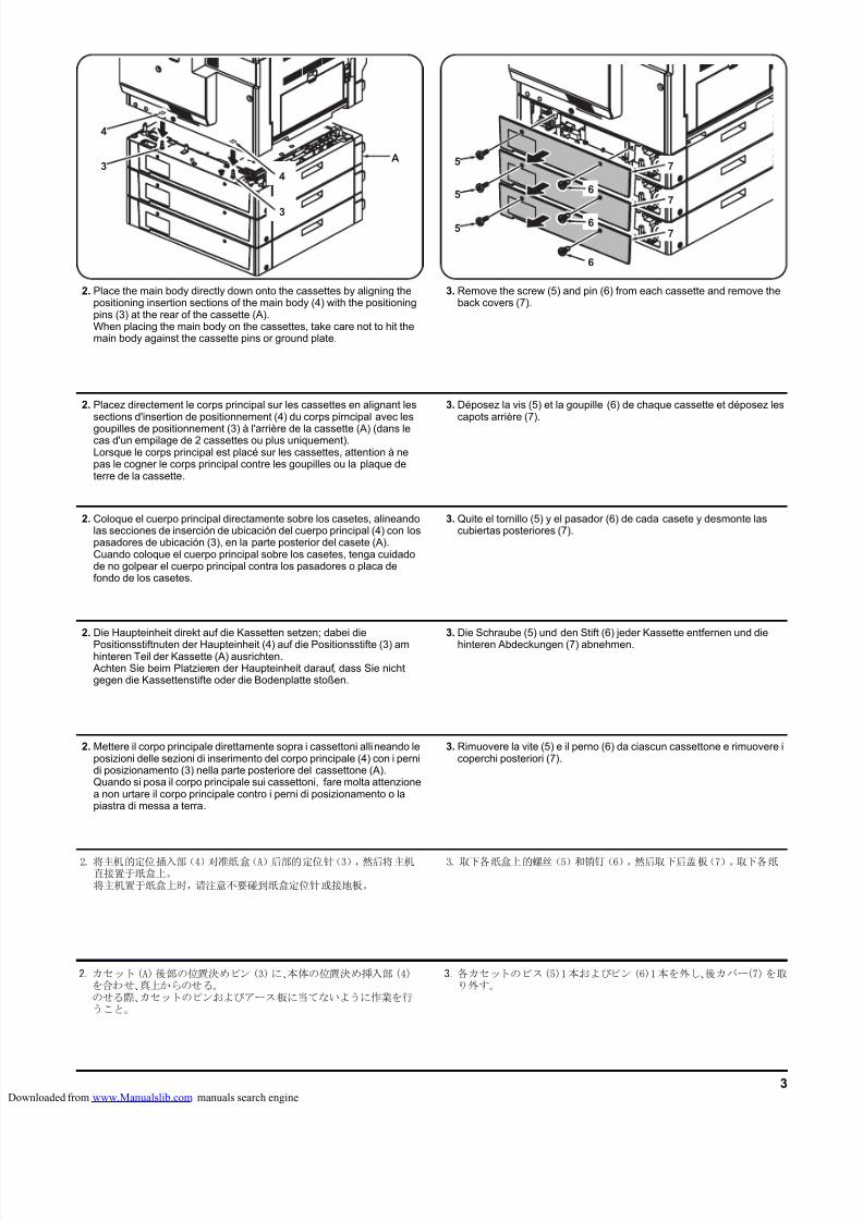
8/18/2019 taskalfa_220
http://slidepdf.com/reader/full/taskalfa220 277/3003
5
5
5
6
7
6
6
7
7
A
3
4
3
4
2. Place the main body directly down onto the cassettes by aligning thepositioning insertion sections of the main body (4) with the positioningpins (3) at the rear of the cassette (A).When placing the main body on the cassettes, take care not to hit themain body against the cassette pins or ground plate.
3. Remove the screw (5) and pin (6) from each cassette and remove theback covers (7).
2. Placez directement le corps principal sur les cassettes en alignant lessections d'insertion de positionnement (4) du corps pirncipal avec les
goupilles de positionnement (3) à l'arrière de la cassette (A) (dans lecas d'un empilage de 2 cassettes ou plus uniquement).Lorsque le corps principal est placé sur les cassettes, attention à nepas le cogner le corps principal contre les goupilles ou la plaque deterre de la cassette.
3. Déposez la vis (5) et la goupille (6) de chaque cassette et déposez lescapots arrière (7).
2. Coloque el cuerpo principal directamente sobre los casetes, alineandolas secciones de inserción de ubicación del cuerpo principal (4) con lospasadores de ubicación (3), en la parte posterior del casete (A).Cuando coloque el cuerpo principal sobre los casetes, tenga cuidadode no golpear el cuerpo principal contra los pasadores o placa defondo de los casetes.
3. Quite el tornillo (5) y el pasador (6) de cada casete y desmonte lascubiertas posteriores (7).
2. Die Haupteinheit direkt auf die Kassetten setzen; dabei die
Positionsstiftnuten der Haupteinheit (4) auf die Positionsstifte (3) amhinteren Teil der Kassette (A) ausrichten.
Achten Sie beim Platzieren der Haupteinheit darauf, dass Sie nichtgegen die Kassettenstifte oder die Bodenplatte stoßen.
3. Die Schraube (5) und den Stift (6) jeder Kassette entfernen und die
hinteren Abdeckungen (7) abnehmen.
2. Mettere il corpo principale direttamente sopra i cassettoni allineando leposizioni delle sezioni di inserimento del corpo principale (4) con i pernidi posizionamento (3) nella parte posteriore del cassettone (A).Quando si posa il corpo principale sui cassettoni, fare molta attenzionea non urtare il corpo principale contro i perni di posizionamento o lapiastra di messa a terra.
3. Rimuovere la vite (5) e il perno (6) da ciascun cassettone e rimuovere icoperchi posteriori (7).
2. 将主机的定位插入部(4)对准纸盒(A)后部的定位针(3),然后将主机直接置于纸盒上。将主机置于纸盒上时,请注意不要碰到纸盒定位针或接地板。
3. 取下各纸盒上的螺丝(5)和销钉(6),然后取下后盖板(7)。取下各纸
2.カセット(A)後部の位置決めピン (3)に、本体の位置決め挿入部(4)を合わせ、真上からのせる。のせる際、カセットのピンおよびアース板に当てないように作業を行うこと。
3.各カセットのビス(5)1本およびピン(6)1本を外し、後カバー(7)を取り外す。
loaded from www.Manualslib.com manuals search engine
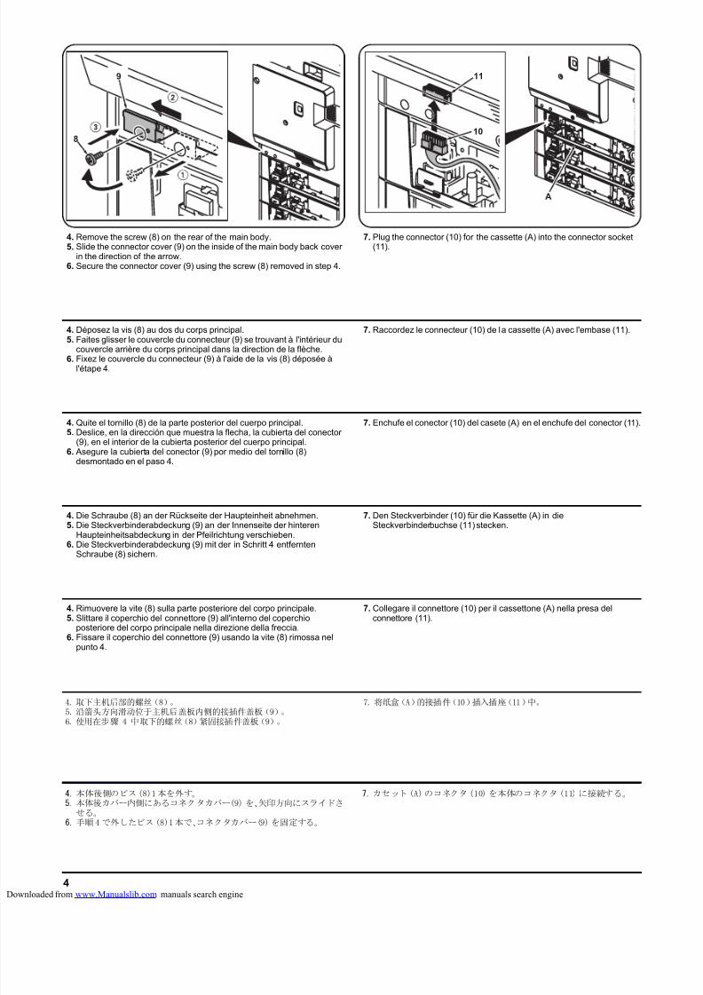
8/18/2019 taskalfa_220
http://slidepdf.com/reader/full/taskalfa220 278/3004
8
9
4. Remove the screw (8) on the rear of the main body.5. Slide the connector cover (9) on the inside of the main body back cover
in the direction of the arrow.6. Secure the connector cover (9) using the screw (8) removed in step 4.
7. Plug the connector (10) for the cassette (A) into the connector socket(11).
4. Déposez la vis (8) au dos du corps principal.5. Faites glisser le couvercle du connecteur (9) se trouvant à l'intérieur du
couvercle arrière du corps principal dans la direction de la flèche.6. Fixez le couvercle du connecteur (9) à l'aide de la vis (8) déposée à
l'étape 4.
7. Raccordez le connecteur (10) de la cassette (A) avec l'embase (11).
4. Quite el tornillo (8) de la parte posterior del cuerpo principal.5. Deslice, en la dirección que muestra la flecha, la cubierta del conector
(9), en el interior de la cubierta posterior del cuerpo principal.6. Asegure la cubierta del conector (9) por medio del tornillo (8)
desmontado en el paso 4.
7. Enchufe el conector (10) del casete (A) en el enchufe del conector (11).
4. Die Schraube (8) an der Rückseite der Haupteinheit abnehmen.
5. Die Steckverbinderabdeckung (9) an der Innenseite der hinterenHaupteinheitsabdeckung in der Pfeilrichtung verschieben.
6. Die Steckverbinderabdeckung (9) mit der in Schritt 4 entferntenSchraube (8) sichern.
7. Den Steckverbinder (10) für die Kassette (A) in die
Steckverbinderbuchse (11) stecken.
4. Rimuovere la vite (8) sulla parte posteriore del corpo principale.5. Slittare il coperchio del connettore (9) all'interno del coperchio
posteriore del corpo principale nella direzione della freccia.6. Fissare il coperchio del connettore (9) usando la vite (8) rimossa nel
punto 4.
7. Collegare il connettore (10) per il cassettone (A) nella presa delconnettore (11).
4.本体後側のビス(8)1本を外す。5.本体後カバー内側にあるコネクタカバー(9) を、矢印方向にスライドさ
せる。6.手順4 で外したビス(8)1本で、コネクタカバー(9)を固定する。
7.カセット (A)のコネクタ(10) を本体のコネクタ(11) に接続する。
4. 取下主机后部的螺丝(8)。5. 沿箭头方向滑动位于主机后盖板内侧的接插件盖板(9)。6. 使用在步骤 4 中取下的螺丝(8)紧固接插件盖板(9)。
7. 将纸盒(A)的接插件(10)插入插座(11)中。
10
A
11
loaded from www.Manualslib.com manuals search engine
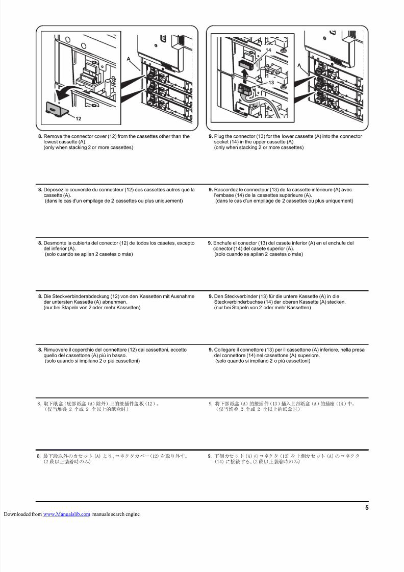
8/18/2019 taskalfa_220
http://slidepdf.com/reader/full/taskalfa220 279/3005
12
A
8. Remove the connector cover (12) from the cassettes other than thelowest cassette (A).(only when stacking 2 or more cassettes)
9. Plug the connector (13) for the lower cassette (A) into the connectorsocket (14) in the upper cassette (A).(only when stacking 2 or more cassettes)
8. Déposez le couvercle du connecteur (12) des cassettes autres que lacassette (A).
(dans le cas d'un empilage de 2 cassettes ou plus uniquement)
9. Raccordez le connecteur (13) de la cassette inférieure (A) avecl'embase (14) de la cassettes supérieure (A).
(dans le cas d'un empilage de 2 cassettes ou plus uniquement)
8. Desmonte la cubierta del conector (12) de todos los casetes, exceptodel inferior (A). (solo cuando se apilan 2 casetes o más)
9. Enchufe el conector (13) del casete inferior (A) en el enchufe delconector (14) del casete superior (A). (solo cuando se apilan 2 casetes o más)
8. Die Steckverbinderabdeckung (12) von den Kassetten mit Ausnahme
der untersten Kassette (A) abnehmen.(nur bei Stapeln von 2 oder mehr Kassetten)
9. Den Steckverbinder (13) für die untere Kassette (A) in die
Steckverbinderbuchse (14) der oberen Kassette (A) stecken.(nur bei Stapeln von 2 oder mehr Kassetten)
8. Rimuovere il coperchio del connettore (12) dai cassettoni, eccettoquello del cassettone (A) più in basso. (solo quando si impilano 2 o più cassettoni)
9. Collegare il connettore (13) per il cassettone (A) inferiore, nella presadel connettore (14) nel cassettone (A) superiore. (solo quando si impilano 2 o più cassettoni)
9.下側カセット(A)のコネクタ(13) を上側カセット (A)のコネクタ(14)に接続する。(2段以上装着時のみ)
9. 将下部纸盒(A)的接插件(13)插入上部纸盒(A)的插座(14)中。(仅当堆叠 2 个或 2 个以上的纸盒时)
13
14
A
8.最下段以外のカセット(A)より、コネクタカバー(12)を取り外す。(2段以上装着時のみ)
8. 取下纸盒(底部纸盒(A)除外)上的接插件盖板(12)。(仅当堆叠 2 个或 2 个以上的纸盒时)
loaded from www.Manualslib.com manuals search engine
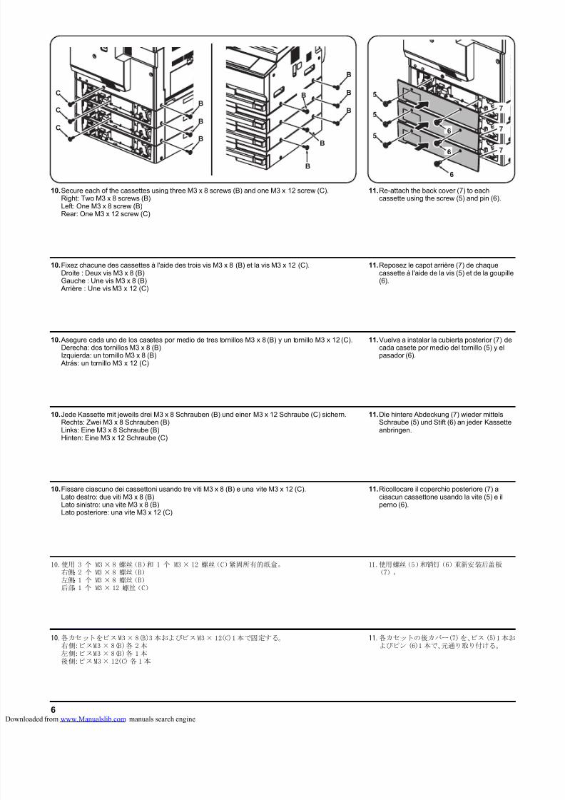
8/18/2019 taskalfa_220
http://slidepdf.com/reader/full/taskalfa220 280/3006
5
5
5
6
7
6
6 7
7
B
BB
B
B
C
C
C
B
B
B
B
11.Re-attach the back cover (7) to eachcassette using the screw (5) and pin (6).
11.Reposez le capot arrière (7) de chaquecassette à l'aide de la vis (5) et de la goupille
(6).
11.Vuelva a instalar la cubierta posterior (7) decada casete por medio del tornillo (5) y elpasador (6).
11.Die hintere Abdeckung (7) wieder mittels
Schraube (5) und Stift (6) an jeder Kassetteanbringen.
11.Ricollocare il coperchio posteriore (7) aciascun cassettone usando la vite (5) e ilperno (6).
11.各カセットの後カバー(7)を、ビス (5)1 本およびピン (6)1 本で、元通り取り付ける。
10.使用 3 个 M3 × 8 螺丝(B)和 1 个 M3 × 12 螺丝(C)紧固所有的纸盒。右侧:2 个 M3 × 8 螺丝(B)左侧:1 个 M3 × 8 螺丝(B)后部:1 个 M3 × 12 螺丝(C)
11.使用螺丝(5)和销钉(6)重新安装后盖板(7)。
10.各カセットをビスM3× 8(B)3 本およびビスM3× 12(C)1本で固定する。右側:ビスM3 × 8(B)各 2本左側:ビスM3 × 8(B)各 1本後側:ビスM3× 12(C) 各 1 本
10.Secure each of the cassettes using three M3 x 8 screws (B) and one M3 x 12 screw (C).Right: Two M3 x 8 screws (B)Left: One M3 x 8 screw (B)Rear: One M3 x 12 screw (C)
10.Fixez chacune des cassettes à l'aide des trois vis M3 x 8 (B) et la vis M3 x 12 (C).Droite : Deux vis M3 x 8 (B)
Gauche : Une vis M3 x 8 (B) Arrière : Une vis M3 x 12 (C)
10. Asegure cada uno de los casetes por medio de tres tornillos M3 x 8 (B) y un tornillo M3 x 12 (C).Derecha: dos tornillos M3 x 8 (B)Izquierda: un tornillo M3 x 8 (B)
Atrás: un tornillo M3 x 12 (C)
10.Jede Kassette mit jeweils drei M3 x 8 Schrauben (B) und einer M3 x 12 Schraube (C) sichern.
Rechts: Zwei M3 x 8 Schrauben (B)Links: Eine M3 x 8 Schraube (B)Hinten: Eine M3 x 12 Schraube (C)
10.Fissare ciascuno dei cassettoni usando tre viti M3 x 8 (B) e una vite M3 x 12 (C).Lato destro: due viti M3 x 8 (B)Lato sinistro: una vite M3 x 8 (B)Lato posteriore: una vite M3 x 12 (C)
loaded from www.Manualslib.com manuals search engine
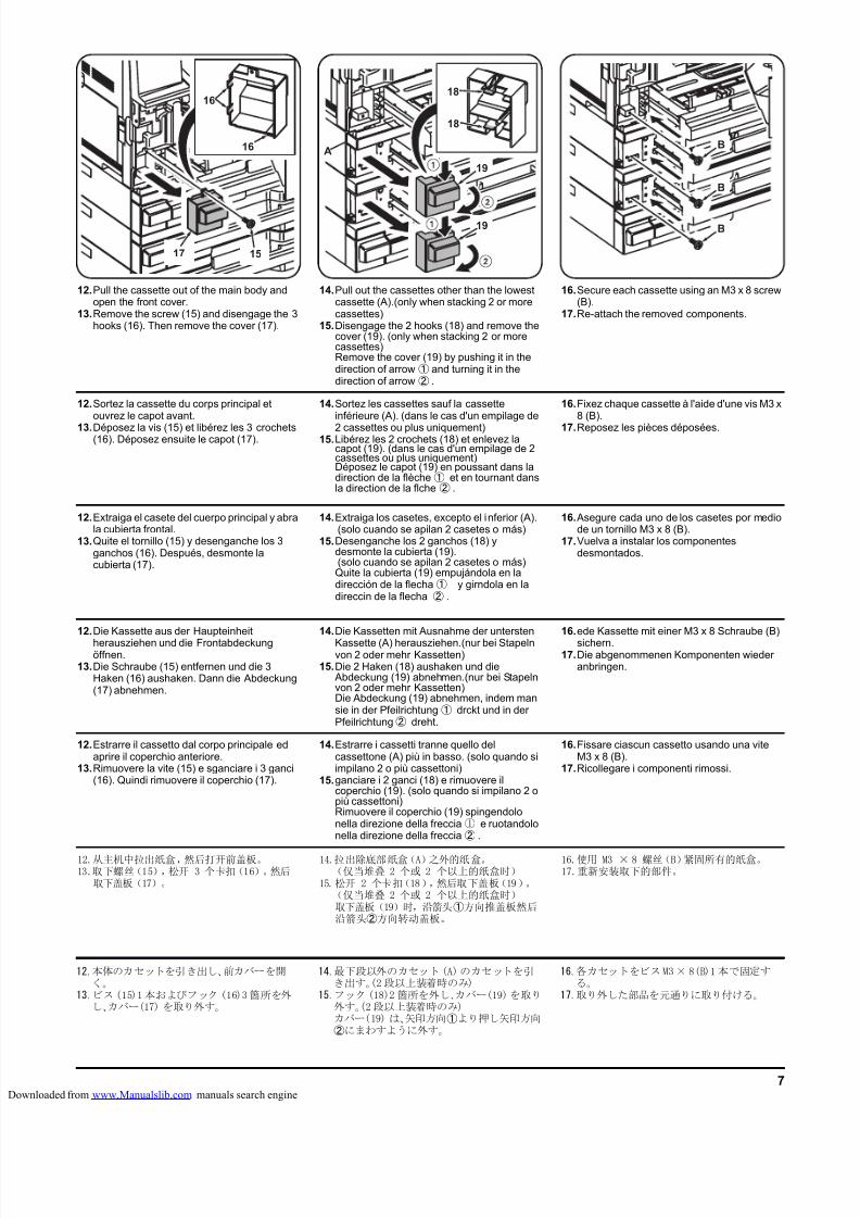
8/18/2019 taskalfa_220
http://slidepdf.com/reader/full/taskalfa220 281/3007
19
19
18
18
A
15
16
16
17
12.本体のカセットを引き出し、前カバーを開く。
13.ビス(15)1本およびフック (16)3箇所を外し、カバー(17) を取り外す。
14.最下段以外のカセット(A)のカセットを引き出す。(2段以上装着時のみ)
15.フック(18)2 箇所を外し、カバー(19)を取り外す。(2段以上装着時のみ)カバー(19) は、矢印方向①より押し矢印方向②にまわすように外す。
16.各カセットをビスM3× 8(B)1本で固定する。
17.取り外した部品を元通りに取り付ける。
12.Pull the cassette out of the main body andopen the front cover.
13.Remove the screw (15) and disengage the 3hooks (16). Then remove the cover (17).
14.Pull out the cassettes other than the lowestcassette (A).(only when stacking 2 or morecassettes)
15.Disengage the 2 hooks (18) and remove thecover (19). (only when stacking 2 or morecassettes)Remove the cover (19) by pushing it in thedirection of arrow① and turning it in thedirection of arrow② .
16.Secure each cassette using an M3 x 8 screw(B).
17.Re-attach the removed components.
12.Sortez la cassette du corps principal etouvrez le capot avant.
13.Déposez la vis (15) et libérez les 3 crochets(16). Déposez ensuite le capot (17).
14.Sortez les cassettes sauf la cassetteinférieure (A). (dans le cas d'un empilage de
2 cassettes ou plus uniquement)15.Libérez les 2 crochets (18) et enlevez la
capot (19). (dans le cas d'un empilage de 2cassettes ou plus uniquement)Déposez le capot (19) en poussant dans ladirection de la flèche① et en tournant dansla direction de la flche ② .
16.Fixez chaque cassette à l'aide d'une vis M3 x8 (B).
17.Reposez les pièces déposées.
12.Extraiga el casete del cuerpo principal y abrala cubierta frontal.
13.Quite el tornillo (15) y desenganche los 3ganchos (16). Después, desmonte lacubierta (17).
14.Extraiga los casetes, excepto el inferior (A). (solo cuando se apilan 2 casetes o más)
15.Desenganche los 2 ganchos (18) ydesmonte la cubierta (19). (solo cuando se apilan 2 casetes o más)Quite la cubierta (19) empujándola en ladirección de la flecha① y girndola en ladireccin de la flecha ② .
16. Asegure cada uno de los casetes por mediode un tornillo M3 x 8 (B).
17.Vuelva a instalar los componentesdesmontados.
12.Die Kassette aus der Haupteinheit
herausziehen und die Frontabdeckungöffnen.
13.Die Schraube (15) entfernen und die 3Haken (16) aushaken. Dann die Abdeckung(17) abnehmen.
14.Die Kassetten mit Ausnahme der untersten
Kassette (A) herausziehen.(nur bei Stapelnvon 2 oder mehr Kassetten)
15.Die 2 Haken (18) aushaken und die Abdeckung (19) abnehmen.(nur bei Stapelnvon 2 oder mehr Kassetten)Die Abdeckung (19) abnehmen, indem mansie in der Pfeilrichtung① drckt und in derPfeilrichtung② dreht.
16.ede Kassette mit einer M3 x 8 Schraube (B)
sichern.17.Die abgenommenen Komponenten wieder
anbringen.
12.Estrarre il cassetto dal corpo principale edaprire il coperchio anteriore.
13.Rimuovere la vite (15) e sganciare i 3 ganci(16). Quindi rimuovere il coperchio (17).
14.Estrarre i cassetti tranne quello delcassettone (A) più in basso. (solo quando siimpilano 2 o più cassettoni)
15.ganciare i 2 ganci (18) e rimuovere ilcoperchio (19). (solo quando si impilano 2 opiù cassettoni)Rimuovere il coperchio (19) spingendolonella direzione della freccia ① e ruotandolonella direzione della freccia② .
16.Fissare ciascun cassetto usando una viteM3 x 8 (B).
17.Ricollegare i componenti rimossi.
12.从主机中拉出纸盒,然后打开前盖板。13.取下螺丝(15),松开 3 个卡扣(16)。然后
取下盖板(17)。
14.拉出除底部纸盒(A)之外的纸盒。(仅当堆叠 2 个或 2 个以上的纸盒时)
15.松开 2 个卡扣(18),然后取下盖板(19)。(仅当堆叠 2 个或 2 个以上的纸盒时)取下盖板(19)时,沿箭头①方向推盖板然后沿箭头②方向转动盖板。
16.使用 M3 × 8 螺丝(B)紧固所有的纸盒。17.重新安装取下的部件。
B
B
B
loaded from www.Manualslib.com manuals search engine
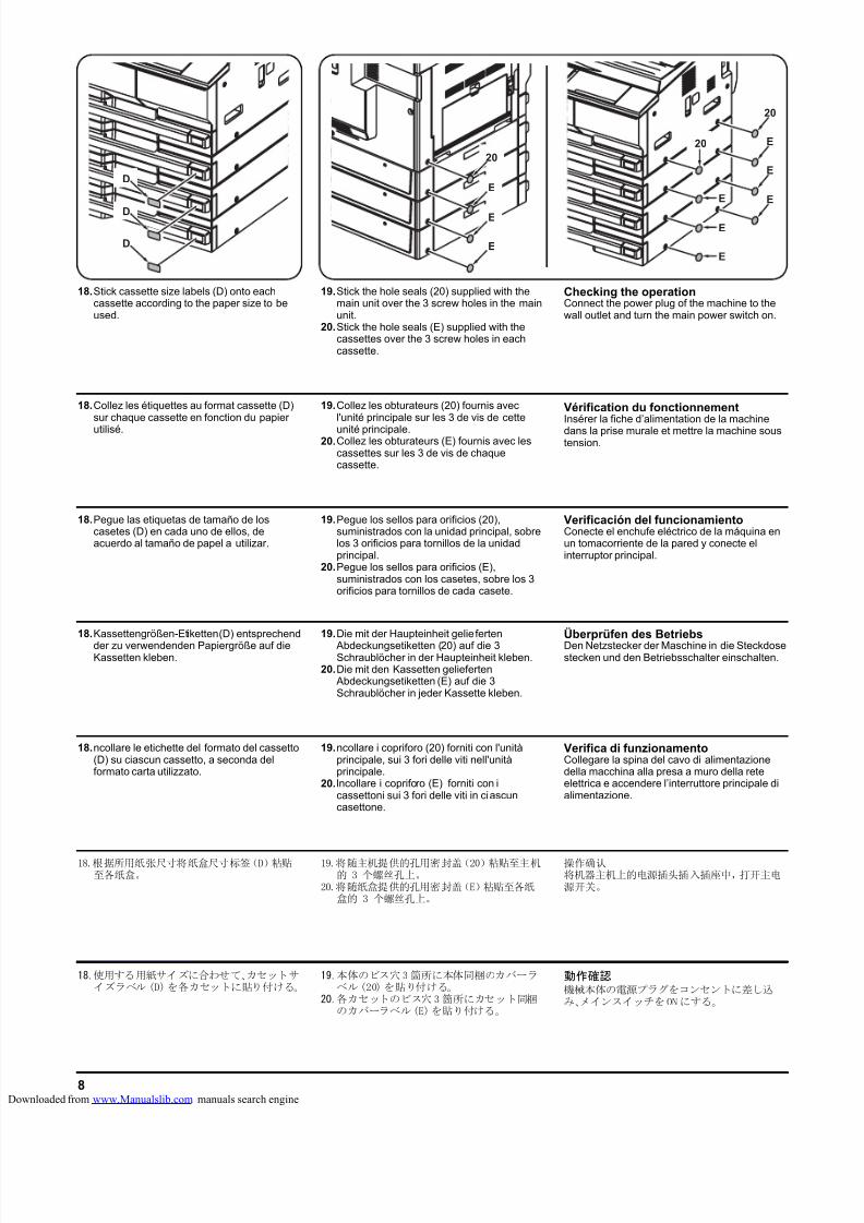
8/18/2019 taskalfa_220
http://slidepdf.com/reader/full/taskalfa220 282/3008
20
E
E
E
20
20
E
E
E
E
E
E
D
D
D
18.Stick cassette size labels (D) onto eachcassette according to the paper size to beused.
19.Stick the hole seals (20) supplied with themain unit over the 3 screw holes in the mainunit.
20.Stick the hole seals (E) supplied with thecassettes over the 3 screw holes in eachcassette.
Checking the operationConnect the power plug of the machine to thewall outlet and turn the main power switch on.
18.Collez les étiquettes au format cassette (D)sur chaque cassette en fonction du papier
utilisé.
19.Collez les obturateurs (20) fournis avecl'unité principale sur les 3 de vis de cette
unité principale.20.Collez les obturateurs (E) fournis avec les
cassettes sur les 3 de vis de chaquecassette.
Vérification du fonctionnementInsérer la fiche d’alimentation de la machine
dans la prise murale et mettre la machine soustension.
18.Pegue las etiquetas de tamaño de loscasetes (D) en cada uno de ellos, deacuerdo al tamaño de papel a utilizar.
19.Pegue los sellos para orificios (20),suministrados con la unidad principal, sobrelos 3 orificios para tornillos de la unidadprincipal.
20.Pegue los sellos para orificios (E),suministrados con los casetes, sobre los 3orificios para tornillos de cada casete.
Verificación del funcionamientoConecte el enchufe eléctrico de la máquina enun tomacorriente de la pared y conecte elinterruptor principal.
18.Kassettengrößen-Etiketten (D) entsprechend
der zu verwendenden Papiergröße auf dieKassetten kleben.
19.Die mit der Haupteinheit gelieferten
Abdeckungsetiketten (20) auf die 3Schraublöcher in der Haupteinheit kleben.
20.Die mit den Kassetten gelieferten Abdeckungsetiketten (E) auf die 3Schraublöcher in jeder Kassette kleben.
Überprüfen des BetriebsDen Netzstecker der Maschine in die Steckdosestecken und den Betriebsschalter einschalten.
18.ncollare le etichette del formato del cassetto(D) su ciascun cassetto, a seconda delformato carta utilizzato.
19.ncollare i copriforo (20) forniti con l'unitàprincipale, sui 3 fori delle viti nell'unitàprincipale.
20. lncollare i copriforo (E) forniti con icassettoni sui 3 fori delle viti in ciascuncasettone.
Verifica di funzionamentoCollegare la spina del cavo di alimentazionedella macchina alla presa a muro della reteelettrica e accendere l’interruttore principale dialimentazione.
18.根据所用纸张尺寸将纸盒尺寸标签(D)粘贴至各纸盒。
19.将随主机提供的孔用密封盖(20)粘贴至主机的 3 个螺丝孔上。
20.将随纸盒提供的孔用密封盖(E)粘贴至各纸盒的 3 个螺丝孔上。
操作确认将机器主机上的电源插头插入插座中,打开主电源开关。
18.使用する用紙サイズに合わせて、カセットサイズラベル (D)を各カセットに貼り付ける。
19.本体のビス穴3箇所に本体同梱のカバーラベル(20) を貼り付ける。
20.各カセットのビス穴 3 箇所にカセット同梱のカバーラベル(E)を貼り付ける。
動作確認機械本体の電源プラグをコンセントに差し込み、メインスイッチをONにする。
loaded from www.Manualslib.com manuals search engine
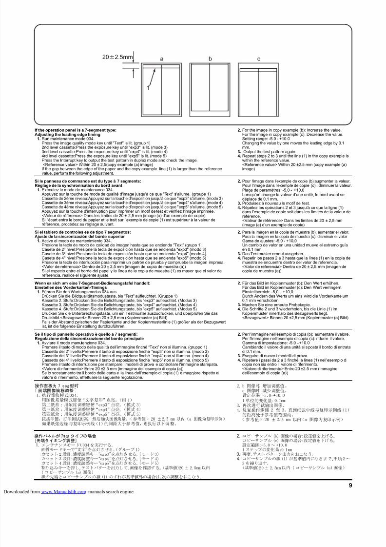
8/18/2019 taskalfa_220
http://slidepdf.com/reader/full/taskalfa220 283/3009
Se il tipo di pannello operativo è quello a 7 segmenti:Regolazione della sincronizzazione del bordo principale
1. Avviare il modo manutenzione 034.Premere il tasto di modo della qualità dell’immagine finché “Text” non si illumina. (gruppo 1)Cassetto del 2° livello:Premere il tasto di esposizione finché “exp3” non si illumina. (modo 3)Cassetto del 3° livello:Premere il tasto di esposizione finché “exp4” non si illumina. (modo 4)Cassetto del 4° livello:Premere il tasto di esposizione finché “exp5” non si illumina. (modo 5)Premere il tasto di interruzione per stampare i modelli di prova e controllare l'immagine stampata.<Valore di riferimento> Entro 20 ±2.5 mm (immagine dell'esempio di copia (a))Se lo scostamento tra il bordo della carta e la linea dell'esempio di copia (1) è maggiore rispetto alvalore di riferimento, effettuare la seguente regolazione.
2. Per l'immagine nell'esempio di copia (b): aumentare il valore.Per l'immagine nell'esempio di copia (c): ridurre il valore.Gamma di impostazione: -5.0 –+10.0Cambiando il valore di una unità si sposta il bordo di entratadi 0.1 mm.
3. Eseguire di nuovo i modelli di prova.4. Ripetere i passi da 2 a 3 finché la linea (1) nell'esempio di
copia non sia entro il valore di riferimento.<Valore di riferimento> Entro 20 ±2.5 mm (immaginedell'esempio di copia (a))
Wenn es sich um eine 7-Segment-Bedienungstafel handelt:
Einstellen des Vorderkanten-Timings1. Führen Sie den Wartungsmodus 034 aus.Drücken Sie die Bildqualitätsmodustaste, bis "Text" aufleuchtet. (Gruppe 1)Kassette 2. Stufe:Drücken Sie die Belichtungstaste, bis "exp3" aufleuchtet. (Modus 3)Kassette 3. Stufe:Drücken Sie die Belichtungstaste, bis "exp4" aufleuchtet. (Modus 4)Kassette 4. Stufe:Drücken Sie die Belichtungstaste, bis "exp5" aufleuchtet. (Modus 5)Drücken Sie die Unterbrechungstaste, um ein Testmuster auszudrucken, und überprüfen Sie dasDruckbild.<Bezugswert> Binnen 20 ± 2,5 mm (Kopienmuster (a) Bild)Falls der Abstand zwischen der Papierkante und der Kopienmusterlinie (1) größer als der Bezugswertist, ist die folgende Einstellung durchzuführen.
2. Für das Bild im Kopienmuster (b): Den Wert erhöhen.
Für das Bild im Kopienmuster (c): Den Wert verringern.Einstellbereich: -5,0 – +10,0Durch Ändern des Werts um eins wird die Vorderkante um0,1 mm verschoben.
3. Machen Sie eine erneute Probekopie.4. Die Schritte 2 und 3 wiederholen, bis die Linie (1) im
Kopienmuster innerhalb des Bezugswerts liegt.<Bezugswert> Binnen 20 ±2,5 mm (Kopienmuster (a) Bild)
Si el tablero de controles es de tipo 7 segmentos:Ajuste de la sincronización del borde superior
1. Active el modo de mantenimiento 034.Presione la tecla de modo de calidad de imagen hasta que se encienda "Text" (grupo 1)Casete de 2º nivel:Presione la tecla de exposición hasta que se encienda "exp3" (modo 3)Casete de 3º nivel:Presione la tecla de exposición hasta que se encienda "exp4" (modo 4).Casete de 4º nivel:Presione la tecla de exposición hasta que se encienda "exp5" (modo 5)Presione la tecla de interrupción para imprimir un patrón de prueba y compruebe la imagen impresa.<Valor de referencia> Dentro de 20 ± 2,5 mm (imagen de copia de muestra (a))Si el espacio entre el borde del papel y la línea de la copia de muestra (1) es mayor que el valor dereferencia, realice el siguiente ajuste.
2. Para la imagen en la copia de muestra (b): aumentar el valor.Para la imagen en la copia de muestra (c): disminuir el valor Gama de ajustes: -5,0 - +10,0Un cambio de valor en una unidad mueve el extremo guíaen 0,1 mm.
3. Das Testmuster erneut ausgeben.4. Repetir los pasos 2 a 3 hasta que la línea (1) en la copia de
muestra se encuentre dentro del valor de referencia.<Valor de referencia> Dentro de 20 ± 2,5 mm (imagen decopia de muestra (a))
Si le panneau de commande est du type à 7 segments:Réglage de la synchronisation du bord avant
1. Exécutez le mode de maintenance 034. Appuyez sur la touche de mode de qualité d'image jusqu'à ce que "Text" s'allume. (groupe 1)Cassette de 2ème niveau:Appuyez sur la touche d'exposition jusqu'à ce que "exp3" s'allume. (mode 3)Cassette de 3ème niveau:Appuyez sur la touche d'exposition jusqu'à ce que "exp4" s'allume. (mode 4)Cassette de 4ème niveau:Appuyez sur la touche d'exposition jusqu'à ce que "exp5" s'allume. (mode 5)
Appuyez sur la touche d'interruption pour imprimer un motif de test et vérifiez l'image imprimée.<Valeur de référence> Dans les limites de 20 ± 2,5 mm (image (a) d'un exemple de copie)Si l'écart entre le bord du papier et le trait sur l'exemple de copie (1) est supérieur à la valeur deréférence, procédez au réglage suivant.
2. Pour l'image dans l'exemple de copie (b):augmenter la valeur.Pour l'image dans l'exemple de copie (c) : diminuer la valeur.
Plage de paramètres: -5,0 - +10,0Lorsqu’on change la valeur d’une unité, le bord avant sedéplace de 0,1 mm.
3. Produisez à nouveau le motif de test.4. Répétez les opérations 2 et 3 jusqu'à ce que la ligne (1)
dans l'exemple de copie soit dans les limites de la valeur deréférence.<Valeur de référence> Dans les limites de 20 ± 2,5 mm(image (a) d'un exemple de copie)
b ca
1
202.5mm
操作パネルが7seg タイプの場合[先端タイミング調整]1.メンテナンスモードU034を実行する。
画質モードキーで“文字”を点灯させる。(グループ1)カセット2段目:濃度調整キー“exp3”を点灯させる。(モード3)カセット3段目:濃度調整キー“exp4”を点灯させる。(モード4)カセット4段目:濃度調整キー“exp5”を点灯させる。(モード5)割り込みキーを押し、テストパターを出力して、画像を確認する。〈基準値〉20 ± 2.5mm 以内(コピーサンプル(a) 画像)紙の先端とコピーサンプルの線(1) のずれが基準値外の場合は、次の調整をおこなう。
2.コピーサンプル(b) 画像の場合:設定値を上げる。コピーサンプル(c) 画像の場合:設定値を下げる。設定範囲:-5.0~ +10.01 ステップの変化量:0.1mm
3.再度、テストパターン出力をおこなう。4.コピーサンプルの線(1)が基準値内になるまで、手順2~
3を繰り返す。〈基準値〉20± 2.5mm以内 ( コピーサンプル (a)画像)
If the operation panel is a 7-segment type:Adjusting the leading edge timing
1. Run maintenance mode 034.Press the image quality mode key until "Text" is lit. (group 1)2nd level cassette:Press the exposure key until "exp3" is lit. (mode 3)3nd level cassette:Press the exposure key until "exp4" is lit. (mode 4)4rd level cassette:Press the exposure key until "exp5" is lit. (mode 5)Press the Interrupt key to output the test pattern in duplex mode and check the image. <Reference value> Within 20 ± 2.5(copy example (a) image)If the gap between the edge of the paper and the copy example line (1) is larger than the referencevalue, perform the following adjustment.
2. For the image in copy example (b): Increase the value.For the image in copy example (c): Decrease the value.Setting range: -5.0 - +10.0Changing the value by one moves the leading edge by 0.1mm.
3. .Output the test pattern again.4. Repeat steps 2 to 3 until the line (1) in the copy example is
within the reference value.<Reference value> Within 20 ±2.5 mm (copy example (a)image)
操作面板为 7 seg型时[ 前端图像偏移调整]1.执行维修模式034。
用图像质量模式键使“文字复印”点亮。(组 1)第二纸盒 : 用浓度调整键使“exp3”点亮。(模式 3)第三纸盒 : 用浓度调整键使“exp4”点亮。(模式 4)第四纸盒 : 用浓度调整键使“exp5”点亮。(模式 5)按插印键,打印测试图案,然后确认图像质量。<参考值 > 20 ±2.5 mm 以内(a 图像为复印示例)如果纸张边缘与复印示例线(1)的间距大于参考值,则执行以下调整。
2. b 图像时:增加调整值。c 图像时:减少调整值。设定范围:-5.0-+10.01 单位的变化量:0.1mm
3.再次进行试输出图像。4.反复操作步骤 2 至 3,直到纸张中线与复印示例线(1)
的距离处于参考值范围内。<参考值> 20 ±2.5 mm 以内(a 图像为复印示例)
loaded from www.Manualslib.com manuals search engine
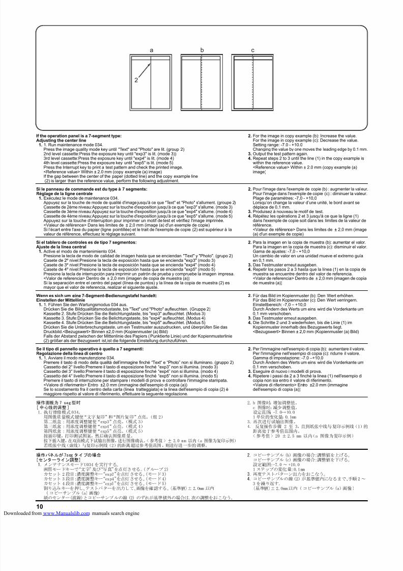
8/18/2019 taskalfa_220
http://slidepdf.com/reader/full/taskalfa220 284/30010
Se il tipo di pannello operativo è quello a 7 segmenti:Regolazione della linea di centro
1. 1. Avviare il modo manutenzione 034.Premere il tasto di modo della qualità dell’immagine finché “Text“ e “Photo” non si illuminano. (gruppo 2)Cassetto del 2° livello:Premere il tasto di esposizione finché “exp3” non si illumina. (modo 3)Cassetto del 3° livello:Premere il tasto di esposizione finché “exp4” non si illumina. (modo 4)Cassetto del 4° livello:Premere il tasto di esposizione finché “exp5” non si illumina. (modo 5)Premere il tasto di interruzione per stampare i modelli di prova e controllare l'immagine stampata.<Valore di riferimento> Entro ±2.0 mm (immagine dell'esempio di copia (a))Se lo scostamento fra il centro della carta (linea tratteggiata) e la linea dell'esempio di copia (2) èmaggiore rispetto al valore di riferimento, effettuare la seguente regolazione.
2. Per l'immagine nell'esempio di copia (b): aumentare il valore.Per l'immagine nell'esempio di copia (c): ridurre il valore.Gamma di impostazione: -7.0 –+10.0Durch Ändern des Werts um eins wird die Vorderkante um0,1 mm verschoben.
3. Eseguire di nuovo i modelli di prova.4. Ripetere i passi da 2 a 3 finché la linea (1) nell'esempio di
copia non sia entro il valore di riferimento.<Valore di riferimento> Entro ±2.0 mm (immaginedell'esempio di copia (a))
Wenn es sich um eine 7-Segment-Bedienungstafel handelt:
Einstellen der Mittellinie1. 1. Führen Sie den Wartungsmodus 034 aus.Drücken Sie die Bildqualitätsmodustaste, bis "Text" und "Photo" aufleuchten. (Gruppe 2)Kassette 2. Stufe:Drücken Sie die Belichtungstaste, bis "exp3" aufleuchtet. (Modus 3)Kassette 3. Stufe:Drücken Sie die Belichtungstaste, bis "exp4" aufleuchtet. (Modus 4)Kassette 4. Stufe:Drücken Sie die Belichtungstaste, bis "exp5" aufleuchtet. (Modus 5)Drücken Sie die Unterbrechungstaste, um ein Testmuster auszudrucken, und überprüfen Sie dasDruckbild.<Bezugswert> Binnen ±2,0 mm (Kopienmuster (a) Bild)Falls der Abstand zwischen der Mittenlinie des Papiers (Punktierte Linie) und der Kopienmusterlinie(2) größer als der Bezugswert ist,ist die folgende Einstellung durchzuführen.
2. Für das Bild im Kopienmuster (b): Den Wert erhöhen.
Für das Bild im Kopienmuster (c): Den Wert verringern.Einstellbereich: -7,0 – +10,0Durch Ändern des Werts um eins wird die Vorderkante um0,1 mm verschoben.
3. Das Testmuster erneut ausgeben.4. Die Schritte 2 und 3 wiederholen, bis die Linie (1) im
Kopienmuster innerhalb des Bezugswerts liegt.<Bezugswert> Binnen ± 2,0 mm (Kopienmuster (a) Bild)
Si el tablero de controles es de tipo 7 segmentos:Ajuste de la línea central
1. Active el modo de mantenimiento 034.Presione la tecla de modo de calidad de imagen hasta que se enciendan "Text" y "Photo". (grupo 2)Casete de 2º nivel:Presione la tecla de exposición hasta que se encienda "exp3" (modo 3)Casete de 3º nivel:Presione la tecla de exposición hasta que se encienda "exp4" (modo 4)Casete de 4º nivel:Presione la tecla de exposición hasta que se encienda "exp5" (modo 5)Presione la tecla de interrupción para imprimir un patrón de prueba y compruebe la imagen impresa.<Valor de referencia> Dentro de ± 2,0 mm (imagen de copia de muestra (a))Si la separación entre el centro del papel (línea de puntos) y la línea de la copia de muestra (2) esmayor que el valor de referencia, realizar el siguiente ajuste.
2. Para la imagen en la copia de muestra (b): aumentar el valor.Para la imagen en la copia de muestra (c): disminuir el valor.Gama de ajustes: -7,0 - +10,0Un cambio de valor en una unidad mueve el extremo guíaen 0,1 mm.
3. Das Testmuster erneut ausgeben.4. Repetir los pasos 2 a 3 hasta que la línea (1) en la copia de
muestra se encuentre dentro del valor de referencia.<Valor de referencia> Dentro de ± 2,0 mm (imagen de copiade muestra (a))
Si le panneau de commande est du type à 7 segments:Réglage de la ligne centrale
1. Exécutez le mode de maintenance 034. Appuyez sur la touche de mode de qualité d'image jusqu'à ce que "Text" et "Photo" s'allument. (groupe 2)Cassette de 2ème niveau:Appuyez sur la touche d'exposition jusqu'à ce que "exp3" s'allume. (mode 3)Cassette de 3ème niveau:Appuyez sur la touche d'exposition jusqu'à ce que "exp4" s'allume. (mode 4)Cassette de 4ème niveau:Appuyez sur la touche d'exposition jusqu'à ce que "exp5" s'allume. (mode 5)
Appuyez sur la touche d'interruption pour imprimer un motif de test et vérifiez l'image imprimée.<Valeur de référence> Dans les limites de ± 2,0 mm (image (a) d'un exemple de copie)Si l’écart entre l'axe du papier (ligne pointillée) et le trait de l'exemple de copie (2) est supérieur à lavaleur de référence, effectuez le réglage suivant.
2. Pour l'image dans l'exemple de copie (b) : augmenter la valeur.Pour l'image dans l'exemple de copie (c) : diminuer la valeur.
Plage de paramètres: -7,0 - +10,0Lorsqu’on change la valeur d’une unité, le bord avant sedéplace de 0,1 mm.
3. Produisez à nouveau le motif de test.4. Répétez les opérations 2 et 3 jusqu'à ce que la ligne (1)
dans l'exemple de copie soit dans les limites de la valeur deréférence.<Valeur de référence> Dans les limites de ± 2,0 mm (image(a) d'un exemple de copie)
If the operation panel is a 7-segment type:Adjusting the center line
1. 1. Run maintenance mode 034.Press the image quality mode key until "Text" and "Photo" are lit. (group 2)2nd level cassette:Press the exposure key until "exp3" is lit. (mode 3))3rd level cassette:Press the exposure key until "exp4" is lit. (mode 4)4th level cassette:Press the exposure key until "exp5" is lit. (mode 5)Press the Interrupt key to print a test pattern and check the printed image.<Reference value> Within ± 2.0 mm (copy example (a) image)If the gap between the center of the paper (dotted line) and the copy example line (2) is larger than the reference value, perform the following adjustment.
2. For the image in copy example (b): Increase the value.For the image in copy example (c): Decrease the value.Setting range: -7.0 - +10.0Changing the value by one moves the leading edge by 0.1 mm.
3. Output the test pattern again.4. Repeat steps 2 to 3 until the line (1) in the copy example is
within the reference value.<Reference value> Within ± 2.0 mm (copy example (a)image)
b ca
2
操作パネルが7seg タイプの場合[センターライン調整]1.メンテナンスモードU034を実行する。
画質モードキーで“文字”及び“写真”を点灯させる。(グループ2)カセット 2段目:濃度調整キー“exp3”を点灯させる。(モード3)カセット 3段目:濃度調整キー“exp4”を点灯させる。(モード4)カセット 4段目:濃度調整キー“exp5”を点灯させる。(モード5)割り込みキーを押し、テストパターを出力して、画像を確認する。〈基準値〉±2.0mm 以内 (コピーサンプル(a)画像)紙のセンター(波線)とコピーサンプルの線 (2) のずれが基準値外の場合は、次の調整をおこなう。
2.コピーサンプル(b) 画像の場合:調整値を上げる。コピーサンプル(c) 画像の場合:調整値を下げる。設定範囲:-7.0~ +10.01 ステップの変化量:0.1mm
3.再度テストパターン出力をおこなう。4.コピーサンプルの線(2)が基準値内になるまで、手順2~
3を繰り返す。〈基準値〉±2.0mm以内 (コピーサンプル(a)画像)
操作面板为7 seg型时[中心线的调整]1. 执行维修模式034。
用图像质量模式键使“文字复印”和“图片复印”点亮。(组 2)第二纸盒 :用浓度调整键使“exp3”点亮。(模式 3)第三纸盒 :用浓度调整键使“exp4”点亮。(模式 4)第四纸盒 :用浓度调整键使“exp5”点亮。(模式 5)按插印键,打印测试图案,然后确认图像质量。按下插入键,在双面模式下试输出图像,进行图像确认。<参考值 > ± 2.0 mm 以内(a 图像为复印示例)若纸张中线(虚线)与复印示例线(2)的距离超过参考值范围,则进行进一步的调整。
2. b 图像时:增加调整值。c 图像时:减少调整值。设定范围:-7.0-+10.01 单位的变化量:0.1mm
3. 再次进行试输出图像。4. 反复操作步骤 2 至 3,直到纸张中线与复印示例线(1)的
距离处于参考值范围内。< 参考值> 20 ± 2.5 mm 以内(a 图像为复印示例)
loaded from www.Manualslib.com manuals search engine
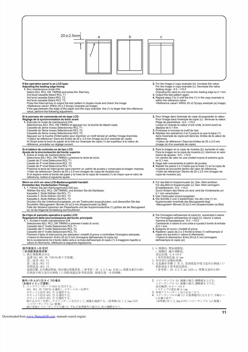
8/18/2019 taskalfa_220
http://slidepdf.com/reader/full/taskalfa220 285/30011
b ca
1
202.5mm
If the operation panel is an LCD type:Adjusting the leading edge timing
1. Run maintenance mode 034.Select ADJ, RCL ON TIMING and press the Start key.2nd level cassette:Select RCL T1.3rd level cassette:Select RCL T2.4rd level cassette:Select RCL T3.Press the Interrupt key to output the test pattern in duplex mode and check the image.<Reference value> Within 20 ± 2.5(copy example (a) image)If the gap between the edge of the paper and the copy example line (1) is larger than the referencevalue, perform the following adjustment.
2. For the image in copy example (b): Increase the value.For the image in copy example (c): Decrease the value.Setting range: -5.0 - +10.0Changing the value by one moves the leading edge by 0.1 mm.
3. Output the test pattern again.4. Repeat steps 2 to 3 until the line (1) in the copy example is
within the reference value.<Reference value> Within 20 ±2.5(copy example (a) image)
Si le panneau de commande est du type LCD:Réglage de la synchronisation du bord avant
1. Exécutez le mode de maintenance 034.Sélectionnez ADJ, RCL ON TIMING et appuyez sur la touche de départ copie.Cassette de 2ème niveau:Sélectionnez RCL T1.Cassette de 3ème niveau:Sélectionnez RCL T2.Cassette de 4ème niveau:Sélectionnez RCL T3.
Appuyez sur la touche d'interruption pour imprimer un motif de test et vérifiez l'image imprimée.<Valeur de référence> Dans les limites de 20 ± 2,5 mm (image (a) d'un exemple de copie)Si l'écart entre le bord du papier et le trait sur l'exemple de copie (1) est supérieur à la valeur deréférence, procédez au réglage suivant.
2. Pour l'image dans l'exemple de copie (b):augmenter la valeur.Pour l'image dans l'exemple de copie (c) : diminuer la valeur.
Plage de paramètres: -5,0 - +10,0Lorsqu’on change la valeur d’une unité, le bord avant sedéplace de 0,1 mm.
3. Produisez à nouveau le motif de test.4. Répétez les opérations 2 et 3 jusqu'à ce que la ligne (1)
dans l'exemple de copie soit dans les limites de la valeur deréférence.<Valeur de référence> Dans les limites de 20 ± 2,5 mm(image (a) d'un exemple de copie).
Si el tablero de controles es de tipo LCD:Ajuste de la sincronización del borde superior
1. Active el modo de mantenimiento 034.Seleccione ADJ, RCL ON TIMING y presione la tecla de inicio.Casete de 2º nivel:Seleccione RCL T1.Casete de 3º nivel:Seleccione RCL T2.Casete de 4º nivel:Seleccione RCL T3.Presione la tecla de interrupción para imprimir un patrón de prueba y compruebe la imagen impresa<Valor de referencia> Dentro de 20 ± 2,5 mm (imagen de copia de muestra (a))Si el espacio entre el borde del papel y la línea de la copia de muestra (1) es mayor que el valor dereferencia, realice el siguiente ajuste.
2. Para la imagen en la copia de muestra (b): aumentar el valor.Para la imagen en la copia de muestra (c): disminuir el valor.Gama de ajustes: -5,0 - +10,0Un cambio de valor en una unidad mueve el extremo guíaen 0,1 mm.
3. Haga salir nuevamente el patrón de prueba.4. Repetir los pasos 2 a 3 hasta que la línea (1) en la copia de
muestra se encuentre dentro del valor de referencia.<Valor de referencia> Dentro de 20 ± 2,5 mm (imagen decopia de muestra (a))
Wenn es sich um eine LCD-Bedienungstafel handelt:
Einstellen des Vorderkanten-Timings1. 1. Führen Sie den Wartungsmodus 034 aus.Wählen Sie ADJ, RCL ON TIMING, und drücken Sie die Starttaste.Kassette 2. Stufe:Wählen Sie RCL T1.Kassette 3. Stufe:Wählen Sie RCL T2.Kassette 4. Stufe:Wählen Sie RCL T3.Drücken Sie die Unterbrechungstaste, um ein Testmuster auszudrucken, und überprüfen Sie dasDruckbild.<Bezugswert> Binnen 20 ±2,5 mm (Kopienmuster (a) Bild)Falls der Abstand zwischen der Papierkante und der Kopienmusterlinie (1) größer als der Bezugswertist, ist die folgende Einstellung durchzuführen.
2. Für das Bild im Kopienmuster (b): Den Wert erhöhen.
Für das Bild im Kopienmuster (c): Den Wert verringern.Einstellbereich: -5,0 - +10,0Durch Ändern des Werts um eins wird die Vorderkante um0,1 mm verschoben.
3. Das Testmuster erneut ausgeben.4. Die Schritte 2 und 3 wiederholen, bis die Linie (1) im
Kopienmuster innerhalb des Bezugswerts liegt.<Bezugswert> Binnen 20 ±2,5 mm (Kopienmuster (a) Bild)
Se il tipo di pannello operativo è quello LCD:Regolazione della sincronizzazione del bordo principale
1. 1. Avviare il modo manutenzione 034.Selezionare ADJ, RCL ON TIMING e premere il tasto di avvio.Cassetto del 2° livello:Selezionare RCL T1.Cassetto del 3° livello:Selezionare RCL T2.Cassetto del 4° livello:Selezionare RCL T3.Premere il tasto di interruzione per stampare i modelli di prova e controllare l'immagine stampata.<Valore di riferimento> Entro 20 ±2.5 mm (immagine dell'esempio di copia (a))Se lo scostamento tra il bordo della carta e la linea dell'esempio di copia (1) è maggiore rispetto alvalore di riferimento, effettuare la seguente regolazione.
2. Per l'immagine nell'esempio di copia (b): aumentare il valore.Per l'immagine nell'esempio di copia (c): ridurre il valore.Gamma di impostazione: -5.0 - +10.0Cambiando il valore di una unità si sposta il bordo di entratadi 0,1 mm.
3. Eseguire di nuovo i modelli di prova.4. Ripetere i passi da 2 a 3 finché la linea (1) nell'esempio di
copia non sia entro il valore di riferimento.<Valore di riferimento> Entro 20 ±2.5 mm (immaginedell'esempio di copia (a))
操作パネルがLCDタイプの場合[先端タイミング調整]1.メンテナンスモードU034を実行する。
ADJ, RCL ON TIMING を選択し、スタートキーを押す。カセット2段目:RCL T1 を選択する。カセット3段目:RCL T2 を選択する。カセット4段目:RCL T3 を選択する。割り込みキーを押し、テストパターンを出力して、画像を確認する。〈基準値〉20± 2.5mm 以内 (コピーサンプル(a) 画像)紙の先端とコピーサンプルの線(1) ずれが基準値外の場合は、次の調整を行う。
2.コピーサンプル(b) 画像の場合:調整値を上げる。コピーサンプル(c) 画像の場合:調整値を下げる。設定範囲:-5.0~ +10.01 ステップの変化量:0.1mm
3.再度テストパターン出力をおこなう。4.コピーサンプルの線(1)が基準値内になるまで、手順2~
3を繰り返す。〈基準値〉20± 2.5mm以内(コピーサンプル(a)画像)
操作面板为 LCD 型时[ 前端图像偏移调整]1.执行维修模式034。
选择ADJ.RCL ON TIMING按下开始键。第二纸盒:RCL T1第三纸盒:RCL T2第四纸盒:RCL T3按插印键,打印测试图案,然后确认图像质量。<参考值> 20 ± 2.5 mm 以内(a 图像为复印示例)若纸张中线与复印示例线(1)的距离超过参考值范围,则进行进一步的调整。
2. b 图像时:增加调整值。c 图像时:减少调整值。设定范围:-5.0-10.01 单位的变化量:0.1mm
3.再次进行试输出图像。4.反复操作步骤 2 至 3,直到纸张中线与复印示例线(1)
的距离处于参考值范围内。<参考值> 20 ±2.5 mm 以内(a 图像为复印示例)
loaded from www.Manualslib.com manuals search engine
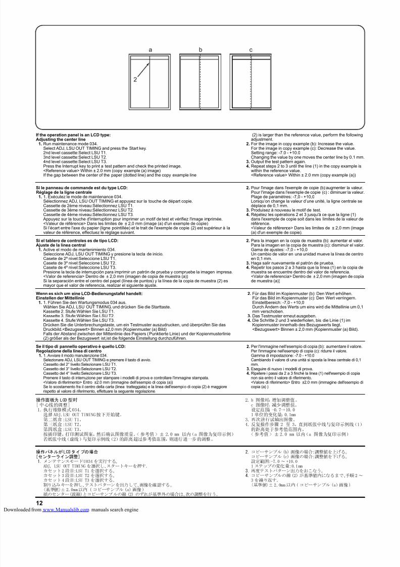
8/18/2019 taskalfa_220
http://slidepdf.com/reader/full/taskalfa220 286/30012
b ca
2
If the operation panel is an LCD type:Adjusting the center line
1. Run maintenance mode 034.Select ADJ, LSU OUT TIMING and press the Start key.2nd level cassette:Select LSU T1.3nd level cassette:Select LSU T2.4nd level cassette:Select LSU T3.Press the Interrupt key to print a test pattern and check the printed image.<Reference value> Within ± 2.0 mm (copy example (a) image)If the gap between the center of the paper (dotted line) and the copy example line
(2) is larger than the reference value, perform the followingadjustment.
2. For the image in copy example (b): Increase the value.For the image in copy example (c): Decrease the value.Setting range: -7.0 - +10.0Changing the value by one moves the center line by 0.1 mm.
3. Output the test pattern again.4. Repeat steps 2 to 3 until the line (1) in the copy example is
within the reference value.<Reference value> Within ± 2.0 mm (copy example (a))
Si le panneau de commande est du type LCD:Réglage de la ligne centrale
1. 1. Exécutez le mode de maintenance 034.Sélectionnez ADJ, LSU OUT TIMING et appuyez sur la touche de départ copie.Cassette de 2ème niveau:Sélectionnez LSU T1.Cassette de 3ème niveau:Sélectionnez LSU T2.Cassette de 4ème niveau:Sélectionnez LSU T3.
Appuyez sur la touche d'interruption pour imprimer un motif de test et vérifiez l'image imprimée.<Valeur de référence> Dans les limites de ± 2,0 mm (image (a) d'un exemple de copie)Si l’écart entre l'axe du papier (ligne pointillée) et le trait de l'exemple de copie (2) est supérieur à lavaleur de référence, effectuez le réglage suivant.
2. Pour l'image dans l'exemple de copie (b):augmenter la valeur.Pour l'image dans l'exemple de copie (c) : diminuer la valeur.
Plage de paramètres: -7,0 - +10,0Lorsqu’on change la valeur d’une unité, la ligne centrale sedéplace de 0,1 mm.
3. Produisez à nouveau le motif de test.4. Répétez les opérations 2 et 3 jusqu'à ce que la ligne (1)
dans l'exemple de copie soit dans les limites de la valeur deréférence.<Valeur de référence> Dans les limites de ± 2,0 mm (image(a) d'un exemple de copie).
Si el tablero de controles es de tipo LCD:Ajuste de la línea central
1. Active el modo de mantenimiento 034.Seleccione ADJ, LSU OUT TIMING y presione la tecla de inicio.Casete de 2º nivel:Seleccione LSU T1.Casete de 3º nivel:Seleccione LSU T2.Casete de 4º nivel:Seleccione LSU T3.Presione la tecla de interrupción para imprimir un patrón de prueba y compruebe la imagen impresa.<Valor de referencia> Dentro de ± 2,0 mm (imagen de copia de muestra (a))Si la separación entre el centro del papel (línea de puntos) y la línea de la copia de muestra (2) esmayor que el valor de referencia, realizar el siguiente ajuste.
2. Para la imagen en la copia de muestra (b): aumentar el valor.Para la imagen en la copia de muestra (c): disminuir el valor.Gama de ajustes: -7,0 - +10,0Un cambio de valor en una unidad mueve la línea de centroen 0,1 mm.
3. Haga salir nuevamente el patrón de prueba.4. Repetir los pasos 2 a 3 hasta que la línea (1) en la copia de
muestra se encuentre dentro del valor de referencia.<Valor de referencia> Dentro de ± 2,0 mm (imagen de copiade muestra (a))
Wenn es sich um eine LCD-Bedienungstafel handelt:
Einstellen der Mittellinie1. 1. Führen Sie den Wartungsmodus 034 aus.Wählen Sie ADJ, LSU OUT TIMING, und drücken Sie die Starttaste.Kassette 2. Stufe:Wählen Sie LSU T1.Kassette 3. Stufe:Wählen Sie LSU T2.Kassette 4. Stufe:Wählen Sie LSU T3.Drücken Sie die Unterbrechungstaste, um ein Testmuster auszudrucken, und überprüfen Sie dasDruckbild.<Bezugswert> Binnen ±2,0 mm (Kopienmuster (a) Bild)Falls der Abstand zwischen der Mittenlinie des Papiers (Punktierte Linie) und der Kopienmusterlinie(2) größer als der Bezugswert ist,ist die folgende Einstellung durchzuführen.
2. Für das Bild im Kopienmuster (b): Den Wert erhöhen.
Für das Bild im Kopienmuster (c): Den Wert verringern.Einstellbereich: -7,0 - +10,0Durch Ändern des Werts um eins wird die Mittellinie um 0,1mm verschoben.
3. Das Testmuster erneut ausgeben.4. Die Schritte 2 und 3 wiederholen, bis die Linie (1) im
Kopienmuster innerhalb des Bezugswerts liegt.<Bezugswert> Binnen ± 2,0 mm (Kopienmuster (a) Bild).
Se il tipo di pannello operativo è quello LCD:Regolazione della linea di centro1. 1. Avviare il modo manutenzione 034.
Selezionare ADJ, LSU OUT TIMING e premere il tasto di avvio.Cassetto del 2° livello:Selezionare LSU T1.Cassetto del 3° livello:Selezionare LSU T2.Cassetto del 4° livello:Selezionare LSU T3.Premere il tasto di interruzione per stampare i modelli di prova e controllare l'immagine stampata.<Valore di riferimento> Entro ±2.0 mm (immagine dell'esempio di copia (a))Se lo scostamento fra il centro della carta (linea tratteggiata) e la linea dell'esempio di copia (2) è maggiorerispetto al valore di riferimento, effettuare la seguente regolazione.
2. Per l'immagine nell'esempio di copia (b): aumentare il valore.Per l'immagine nell'esempio di copia (c): ridurre il valore.Gamma di impostazione: -7.0 - +10.0Cambiando il valore di una unità si sposta la linea centrale di 0,1mm.
3. Eseguire di nuovo i modelli di prova.4. Ripetere i passi da 2 a 3 finché la linea (1) nell'esempio di copia
non sia entro il valore di riferimento.<Valore di riferimento> Entro ±2.0 mm (immagine dell'esempio dicopia (a) )
操作パネルがLCDタイプの場合[センターライン調整]1.メンテナンスモードU034を実行する。
ADJ, LSU OUT TIMING を選択し、スタートキーを押す。カセット2段目:LSU T1 を選択する。カセット3段目:LSU T2 を選択する。カセット4段目:LSU T3 を選択する。割り込みキーを押し、テストパターンを出力して、画像を確認する。〈基準値〉± 2.0mm以内 ( コピーサンプル(a)画像)紙のセンター(波線)とコピーサンプルの線 (2) のずれが基準外の場合は、次の調整を行う。
2.コピーサンプル(b) 画像の場合:調整値を上げる。コピーサンプル(c) 画像の場合:調整値を下げる。設定範囲:-7.0~ +10.01 ステップの変化量:0.1mm
3.再度テストパターン出力をおこなう。4.コピーサンプルの線(2)が基準値内になるまで、手順2~
3を繰り返す。〈基準値〉±2.0mm以内(コピーサンプル (a)画像)
操作面板为 LCD 型时[ 中心线的调整]1.执行维修模式034。
选择ADJ.LSU OUT TIMING按下开始键。第二纸盒:LSU T1。第三纸盒:LSU T2。第四纸盒:LSU T3。按插印键,打印测试图案,然后确认图像质量。< 参考值 > ± 2.0 mm 以内(a 图像为复印示例)若纸张中线(虚线)与复印示例线(2)的距离超过参考值范围,则进行进一步的调整。
2. b 图像时:增加调整值。c 图像时:减少调整值。设定范围:-0.7-+10.01 单位的变化量:0.1mm
3.再次进行试输出图像。4.反复操作步骤 2 至 3,直到纸张中线与复印示例线(1)
的距离处于参考值范围内。<参考值> ± 2.0 mm 以内(a 图像为复印示例)
loaded from www.Manualslib.com manuals search engine

8/18/2019 taskalfa_220
http://slidepdf.com/reader/full/taskalfa220 287/300
INSTALLATION GUIDE FOR
DUPLEX UNIT
loaded from www.Manualslib.com manuals search engine
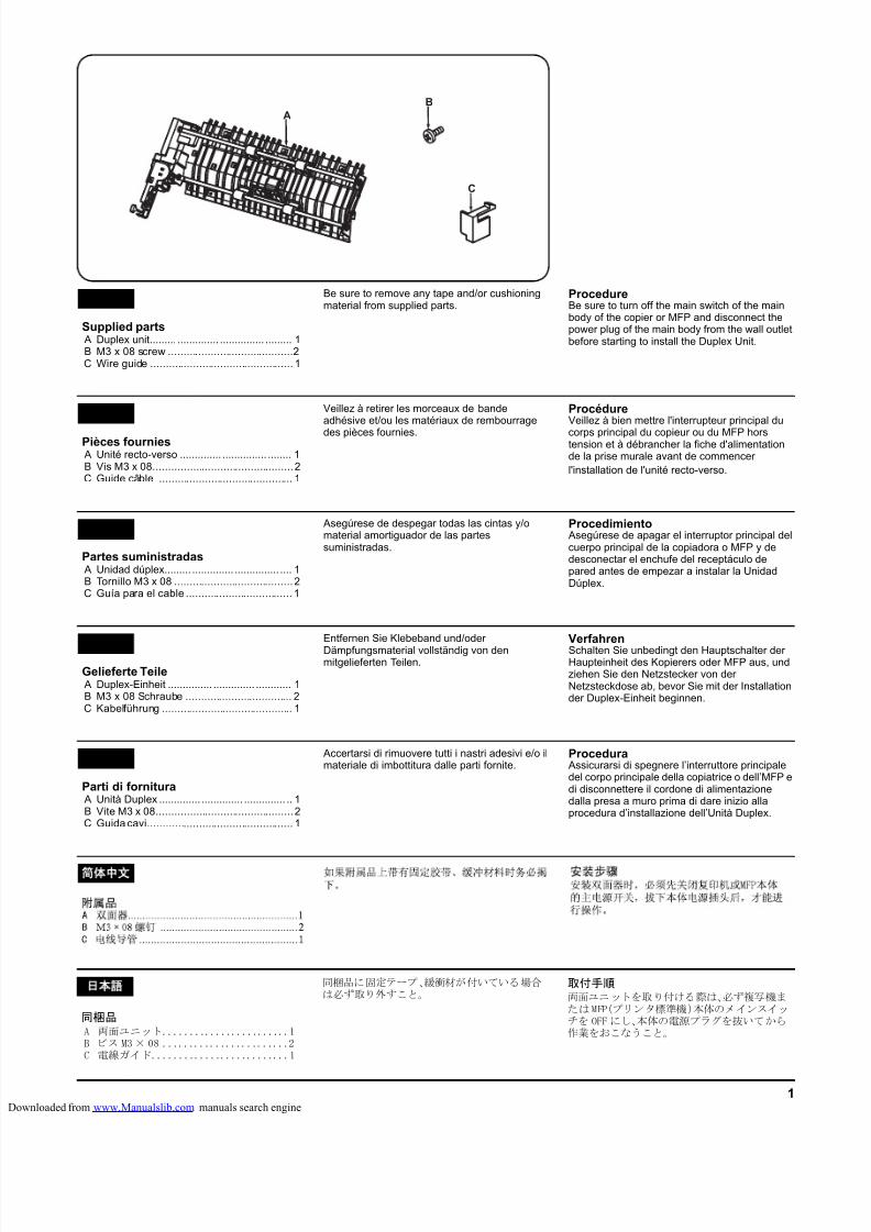
8/18/2019 taskalfa_220
http://slidepdf.com/reader/full/taskalfa220 288/3001
A
B
C
Supplied parts A Duplex unit......... .............. ............... ......... 1B M3 x 08 screw .........................................2C Wire guide ............................................... 1
EnglishBe sure to remove any tape and/or cushioningmaterial from supplied parts.
ProcedureBe sure to turn off the main switch of the mainbody of the copier or MFP and disconnect thepower plug of the main body from the wall outletbefore starting to install the Duplex Unit.
Pièces fournies A Unité recto-verso .............. ............... ........ 1B Vis M3 x 08..............................................2C Guide câble ............................................ 1
FrançaisVeillez à retirer les morceaux de bandeadhésive et/ou les matériaux de rembourrage
des pièces fournies.
ProcédureVeillez à bien mettre l'interrupteur principal du
corps principal du copieur ou du MFP horstension et à débrancher la fiche d'alimentationde la prise murale avant de commencer
l'installation de l'unité recto-verso.
Partes suministradas A Unidad dúplex......... .............. ............... .... 1B Tornillo M3 x 08 .......................................2C Guía para el cable ................................... 1
Español Asegúrese de despegar todas las cintas y/omaterial amortiguador de las partessuministradas.
Procedimiento Asegúrese de apagar el interruptor principal delcuerpo principal de la copiadora o MFP y dedesconectar el enchufe del receptáculo depared antes de empezar a instalar la UnidadDúplex.
Gelieferte Teile A Duplex-Einheit ............... .............. ............ 1B M3 x 08 Schraube ................................... 2C Kabelführung ........................................... 1
Deutsch
Entfernen Sie Klebeband und/oder
Dämpfungsmaterial vollständig von denmitgelieferten Teilen.
VerfahrenSchalten Sie unbedingt den Hauptschalter derHaupteinheit des Kopierers oder MFP aus, undziehen Sie den Netzstecker von derNetzsteckdose ab, bevor Sie mit der Installationder Duplex-Einheit beginnen.
Parti di fornitura A Unità Duplex .............. .............. .............. .. 1B Vite M3 x 08.............................................2C Guida cavi................................................ 1
Italiano Accertarsi di rimuovere tutti i nastri adesivi e/o ilmateriale di imbottitura dalle parti fornite.
Procedura Assicurarsi di spegnere l’interruttore principaledel corpo principale della copiatrice o dell’MFP edi disconnettere il cordone di alimentazionedalla presa a muro prima di dare inizio allaprocedura d’installazione dell’Unità Duplex.
同梱品A 両面ユニット........................1B ビス M3× 08 ........................2C 電線ガイド..........................1
語
同梱品に固定テープ、緩衝材が付いている場合は必ず取り外すこと。
取付手順両面ユニットを取り付ける際は、必ず複写機またはMFP(プリンタ標準機)本体のメインスイッチを OFF にし、本体の電源プラグを抜いてから作業をおこなうこと。
简 文
loaded from www.Manualslib.com manuals search engine
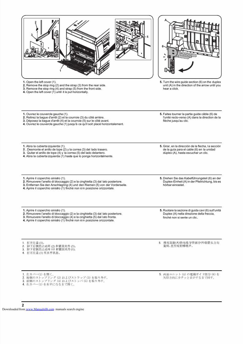
8/18/2019 taskalfa_220
http://slidepdf.com/reader/full/taskalfa220 289/3002
6
A2
1
3
4
5
1. Open the left cover (1).2. Remove the stop ring (2) and the strap (3) from the rear side.3. Remove the stop ring (4) and strap (5) from the front side.4. Open the left cover (1) until it is put horizontally.
5. Turn the wire guide section (6) on the duplexunit (A) in the direction of the arrow until youhear a click.
1. Ouvrez le couvercle gauche (1).2. Retirez la bague d'arrêt (2) et la courroie (3) du côté arrière.
3. Déposez la bague d'arrêt (4) et la courroie (5) sur le côté avant.4. Ouvrez le couvercle gauche (1) jusqu'à ce qu'il soit placé horizontalement.
5. Faites tourner la partie guide câble (6) del'unité recto-verso (A) dans la direction de la
flèche jusqu'au clic.
1. Abra la cubierta izquierda (1).2. .Desmonte el anillo de tope (2) y la correa (3) del lado trasero.3. Quitar el anillo de tope (4) y la correa (5) del lado delantero.4. Abra la cubierta izquierda (1) hasta que lo ponga horizontalmente.
5. Girar, en la dirección de la flecha, la secciónde la guía para el cable (6) en la unidaddúplex (A), hasta escuchar un clic.
1. Aprire il coperchio sinistro (1).
2. Rimuovere l’anello di bloccaggio (2) e la cinghietta (3) dal lato posteriore.3. Entfernen Sie den Anschlagring (4) und den Riemen (5) von der Vorderseite.4. Aprire il coperchio sinistro (1) finché non è in posizione orizzontale.
5. Drehen Sie das Kabelführungsteil (6) an der
Duplex-Einheit (A) in der Pfeilrichtung, bis eshörbar einrastet.
1. Aprire il coperchio sinistro (1).2. Rimuovere l’anello di bloccaggio (2) e la cinghietta (3) dal lato posteriore.3. Rimuovere l'anello di bloccaggio (4) e la cinghietta (5) dal lato fronta.4. Aprire il coperchio sinistro (1) finché non è in posizione orizzontale.
5. Ruotare la sezione di guida cavi (6) sull'unitàDuplex (A) nella direzione della freccia,finché non si sente un clic.
1.左カバー(1)を開く。2.後側のストップリング(2)およびストラップ(3)を取り外す。3.前側のストップリング(4)およびストッパ(5)を取り外す。4.左カバー(1)を水平になるまで開く。
5.両面ユニット(A)の電線ガイド部分(6)を矢印方向にカチッと音がするまで回す。
loaded from www.Manualslib.com manuals search engine
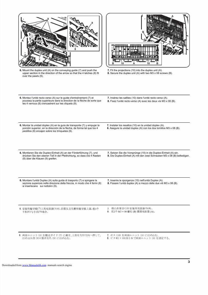
8/18/2019 taskalfa_220
http://slidepdf.com/reader/full/taskalfa220 290/3003
A
B1010 AB
B
BA
7
8
9
8
6. Mount the duplex unit (A) on the conveying guide (7) and push theupper section in the direction of the arrow so that the 4 latches (8) fitover the pawls (9).
7. Fit the projections (10) into the duplex unit (A).8. Secure the duplex unit (A) with two M3 x 08 screws (B).
6. Montez l'unité recto-verso (A) sur le guide d'entraînement (7) etpoussez la partie supérieure dans la direction de la flèche de sorte que
les 4 verrous (8) s'encastrent sur les cliquets (9).
7. Insérez les saillies (10) dans l'unité recto-verso (A).
8. Fixez l'unité recto-verso (A) avec les deux vis M3 x 08 (B).
6. Montar la unidad dúplex (A) en la guía de transporte (7) y empujar laporción superior, en la dirección de la flecha, de forma tal que los 4pestillos (8) encajen sobre los trinquetes (9).
7. Instalar los resaltos (10) en la unidad dúplex (A).8. Asegure la unidad duplex (A) con los dos tornillos M3 x 08 (B).
6. Montieren Sie die Duplex-Einheit (A) an der Förderführung (7), und
drücken Sie den oberen Teil in der Pfeilrichtung, so dass d ie 4 Rasten(8) über die Klauen (9) greifen.
7. Setzen Sie die Vorsprünge (10) in die Duplex-Einheit (A) ein.
8. Die Duplex-Einheit (A) mit den zwei Schrauben M3 x 08 (B) befestigen.
6. Montare l'unità Duplex (A) sulla guida di trasporto (7) e spingere lasezione superiore nella direzione della freccia, in modo che 4 fermi (8)si inseriscano sui nottolini (9).
7. Inserire le sporgenze (10) nell'unità Duplex (A).8. Fissare l’unità duplex (A) a mezzo delle due viti M3 x 08 (B).
6.両面ユニット(A)を搬送ガイド(7)に載せ、上部を矢印方向へ押して、はめ込み部(8)4 箇所を爪 (9)にはめ込む。
7.ボス(10) を両面ユニット (A)にはめ込む。8.ビスM3× 08(B)2本で両面ユニット(A)を固定する。
loaded from www.Manualslib.com manuals search engine
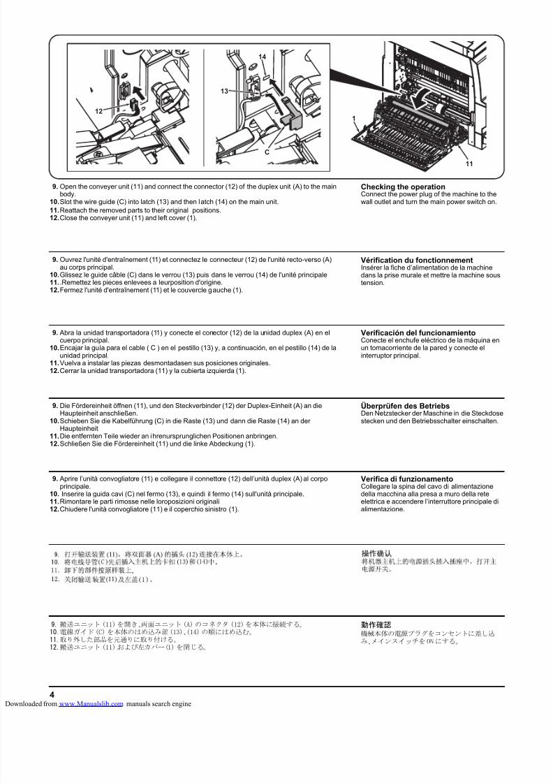
8/18/2019 taskalfa_220
http://slidepdf.com/reader/full/taskalfa220 291/3004
12
C
14
13
11
1
9. Open the conveyer unit (11) and connect the connector (12) of the duplex unit (A) to the mainbody.
10.Slot the wire guide (C) into latch (13) and then latch (14) on the main unit.11.Reattach the removed parts to their original positions.12.Close the conveyer unit (11) and left cover (1).
Checking the operationConnect the power plug of the machine to thewall outlet and turn the main power switch on.
9. Ouvrez l'unité d'entraînement (11) et connectez le connecteur (12) de l'unité recto-verso (A)au corps principal.
10.Glissez le guide câble (C) dans le verrou (13) puis dans le verrou (14) de l'unité principale11. .Remettez les pieces enlevees a leurposition d'origine.12.Fermez l'unité d'entraînement (11) et le couvercle gauche (1).
Vérification du fonctionnementInsérer la fiche d’alimentation de la machine
dans la prise murale et mettre la machine soustension.
9. Abra la unidad transportadora (11) y conecte el conector (12) de la unidad duplex (A) en elcuerpo principal.
10.Encajar la guía para el cable ( C ) en el pestillo (13) y, a continuación, en el pestillo (14) de launidad principal.
11.Vuelva a instalar las piezas desmontadasen sus posiciones originales.12.Cerrar la unidad transportadora (11) y la cubierta izquierda (1).
Verificación del funcionamientoConecte el enchufe eléctrico de la máquina enun tomacorriente de la pared y conecte elinterruptor principal.
9. Die Fördereinheit öffnen (11), und den Steckverbinder (12) der Duplex-Einheit (A) an die
Haupteinheit anschließen.10.Schieben Sie die Kabelführung (C) in die Raste (13) und dann die Raste (14) an der
Haupteinheit11.Die entfernten Teile wieder an ihrenursprunglichen Positionen anbringen.12.Schließen Sie die Fördereinheit (11) und die linke Abdeckung (1).
Überprüfen des BetriebsDen Netzstecker der Maschine in die Steckdosestecken und den Betriebsschalter einschalten.
9. Aprire l’unità convogliatore (11) e collegare il connettore (12) dell’unità duplex (A) al corpoprincipale.
10. Inserire la guida cavi (C) nel fermo (13), e quindi il fermo (14) sull'unità principale.11.Rimontare le parti rimosse nelle loroposizioni originali12.Chiudere l'unità convogliatore (11) e il coperchio sinistro (1).
Verifica di funzionamentoCollegare la spina del cavo di alimentazionedella macchina alla presa a muro della reteelettrica e accendere l’interruttore principale dialimentazione.
9.搬送ユニット(11)を開き、両面ユニット(A)のコネクタ (12)を本体に接続する。10.電線ガイド(C)を本体のはめ込み部(13)、(14)の順にはめ込む。11.取り外した部品を元通りに取り付ける。12.搬送ユニット(11)および左カバー(1)を閉じる。
動作確認機械本体の電源プラグをコンセントに差し込み、メインスイッチをONにする。
loaded from www.Manualslib.com manuals search engine
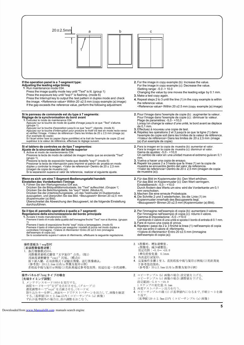
8/18/2019 taskalfa_220
http://slidepdf.com/reader/full/taskalfa220 292/3005
b ca
1
202.5mm
If the operation panel is a 7-segment type:Adjusting the leading edge timing1. Run maintenance mode 034.
Press the image quality mode key until "Text" is lit. (group 1)Press the exposure key until "exp1" is flashing. (mode 6)Press the Interrupt key to output the test pattern in duplex mode and checkthe image. <Reference value> Within 20 ±2.5 mm (copy example (a) image)If the gap exceeds the reference value, perform the following adjustment.
2. For the image in copy example (b): Increase the value.For the image in copy example (c): Decrease the value.ISetting range: -5.0 -+ 10.0Changing the value by one moves the leading edge by 0.1 mm.
3. Make a test copy again.4. Repeat steps 2 to 3 until the line (1) in the copy example is within
the reference value.<Reference value> Within 20 ±2.5 mm (copy example (a) image)
Si le panneau de commande est du type à 7 segments:Réglage de la synchronisation du bord avant
1. Exécutez le mode de maintenance 034. Appuyez sur la touche de mode de qualité d'image jusqu'à ce que "Text" s'allume.(groupe 1) Appuyez sur la touche d'exposition jusqu'à ce que "exp1" clignote. (mode 6) Appuyez sur la touche d'interruption pour produire le motif de test en mode recto-versoet vérifiez l'image. <Valeur de référence> Dans les limites de 20 ± 2,5 mm (image (a)d'un exemple de copie)Si l’écart entre l'axe du papier (ligne pointillée) et le trait de l'exemple de copie (2) estsupérieur à la valeur de référence, effectuez le réglage suivant.
2. Pour l'image dans l'exemple de copie (b) : augmenter la valeur.Pour l'image dans l'exemple de copie (c) : diminuer la valeur.
Plage de paramètres: -5,0 - +10,0Lorsqu’on change la valeur d’une unité, le bord avant se déplacede 0,1 mm.
3. Effectuez à nouveau une copie de test.4. Répétez les opérations 2 et 3 jusqu'à ce que la ligne (1) dans
l'exemple de copie soit dans les limites de la valeur de référence.<Valeur de référence> Dans les limites de 20 ± 2,5 mm (image(a) d'un exemple de copie)
Si el tablero de controles es de tipo 7 segmentos:Ajuste de la sincronización del borde superior
1. Active el modo de mantenimiento 034.Presione la tecla de modo de calidad de imagen hasta que se encienda "Text"(grupo 1)Presione la tecla de exposición hasta que destelle "exp1" (modo 6)Presionar la tecla de interrupción para imprimir el patrón de prueba en mododúplex y controlar la imagen. <Valor de referencia> Dentro de 20 ± 2,5 mm(imagen de copia de muestra (a))Si la separación supera el valor de referencia, realizar el siguiente ajuste.
2. Para la imagen en la copia de muestra (b): aumentar el valor.Para la imagen en la copia de muestra (c): disminuir el valor.Gama de ajustes: -5,0 - +10,0Un cambio de valor en una unidad mueve el extremo guía en 0,1mm.
3. Vuelva a hacer una copia de ensayo.4. Repetir los pasos 2 a 3 hasta que la línea (1) en la copia de
muestra se encuentre dentro del valor de referencia.<Valor de referencia> Dentro de 20 ± 2,5 mm (imagen de copiade muestra (a)).
Wenn es sich um eine 7-Segment-Bedienungstafel handelt:
Einstellen des Vorderkanten-Timings1. Führen Sie den Wartungsmodus 034 aus.
Drücken Sie die Bildqualitätsmodustaste, bis "Text" aufleuchtet. (Gruppe 1)Drücken Sie die Belichtungstaste, bis "exp1" blinkt. (Modus 6)Drücken Sie die Unterbrechungstaste, um das Testmuster im Duplexmodusauszugeben, und überprüfen Sie das Bild. <Bezugswert> Binnen 20 ±2,5 mm(Kopienmuster (a) Bild).Überschreitet die Abweichung den Bezugswert, ist die folgende Einstellungdurchzuführen.
2. Für das Bild im Kopienmuster (b): Den Wert erhöhen.
Für das Bild im Kopienmuster (c): Den Wert verringern.Einstellbereich: -5,0 – +10,0Durch Ändern des Werts um eins wird die Vorderkante um 0,1mm verschoben.
3. Machen Sie eine erneute Probekopie.4. Die Schritte 2 und 3 wiederholen, bis die Linie (1) im
Kopienmuster innerhalb des Bezugswerts liegt.<Bezugswert> Binnen 20 ±2,5 mm (Kopienmuster (a) Bild).
Se il tipo di pannello operativo è quello a 7 segmenti:Regolazione della sincronizzazione del bordo principale1. Avviare il modo manutenzione 034.
Premere il tasto di modo della qualità dell’immagine finché “Text” non si illumina. (gruppo1)Premere il tasto di esposizione finché “expl” inizia a lampeggiare. (modo 6)Premere il tasto di interruzione per eseguire i modelli di prova nel modo duplex econtrollare l’immagine. <Valore di riferimento> Entro 20 ±2.5 mm (immaginedell'esempio di copia (a))Se lo scostamento supera il valore di riferimento, effettuare la seguente regolazione.
2. Per l'immagine nell'esempio di copia (b): aumentare il valore.Per l'immagine nell'esempio di copia (c): ridurre il valore.Gamma di impostazione: -5.0 –+10.0Cambiando il valore di una unità si sposta il bordo di entrata di 0.1 mm.
3. Fare di nuovo una copia di prova.4. Ripetere i passi da 2 a 3 finché la linea (1) nell'esempio di copia
non sia entro il valore di riferimento.<Valore di riferimento> Entro 20 ±2.5 mm (immaginedell'esempio di copia (a))
操作パネルが7segタイプの場合
[先端タイミング調整]
1.メンテナンスモード U034を実行する。画質モードキーで“文字”を点灯させる。(グループ1)濃度調整キーで“exp1”を点滅させる。(モード 6)割り込みキーを押し、両面モードでテストパターンを出力して、画像を確認する。〈基準値〉20± 2.5mm 以内(コピーサンプル (a)画像)ずれが基準値外の場合は、次の調整をおこなう。
2.コピーサンプル(b)画像の場合:設定値を上げる。コピーサンプル(c)画像の場合:調整値を下げる。設定範囲:-5.0 ~ +10.01 ステップの変化量:0.1mm
3.再度テストパターン出力を行う。4.コピーサンプルの線(1)が基準値内になるまで、手順2~ 3を繰
り返す。〈基準値〉20± 2.5mm以内 ( コピーサンプル (a)画像)
loaded from www.Manualslib.com manuals search engine
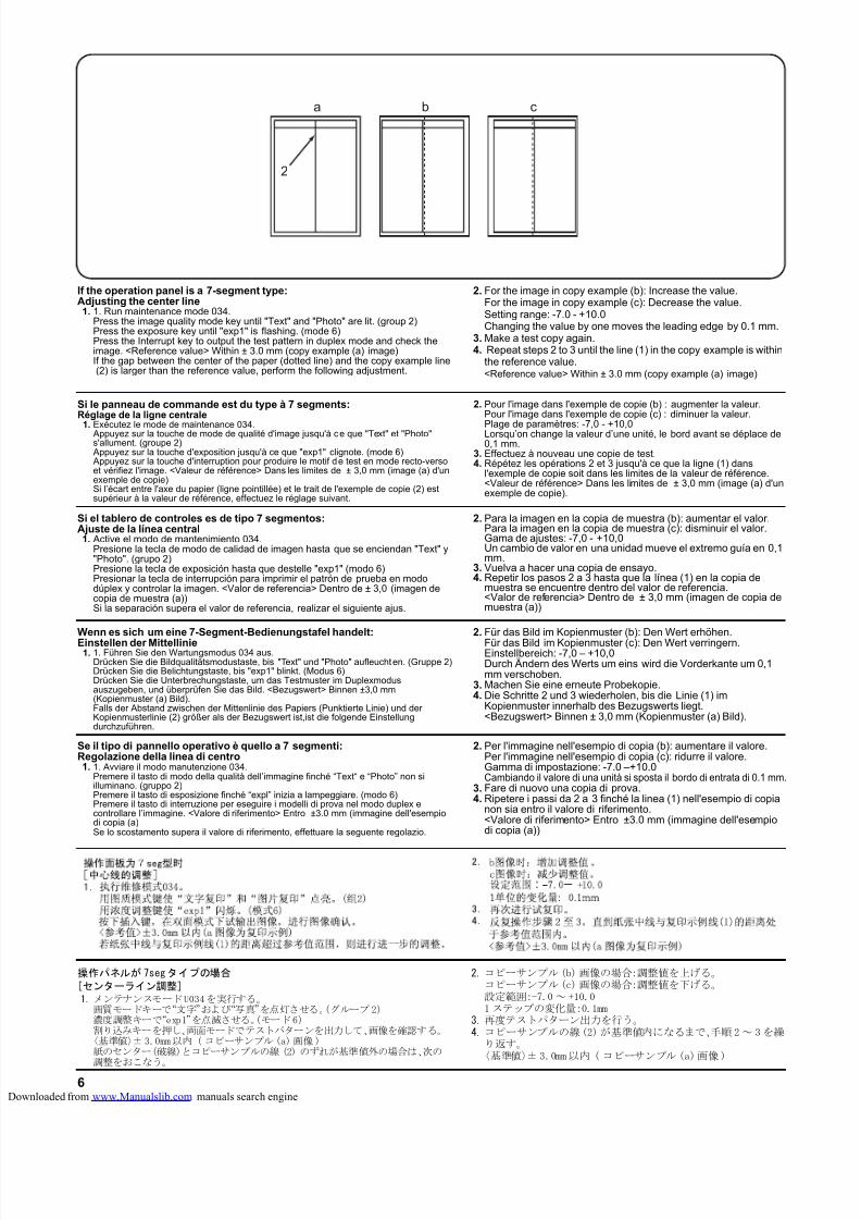
8/18/2019 taskalfa_220
http://slidepdf.com/reader/full/taskalfa220 293/3006
b ca
2
If the operation panel is a 7-segment type:Adjusting the center line1. 1. Run maintenance mode 034.
Press the image quality mode key until "Text" and "Photo" are lit. (group 2)Press the exposure key until "exp1" is flashing. (mode 6)Press the Interrupt key to output the test pattern in duplex mode and check theimage. <Reference value> Within ± 3.0 mm (copy example (a) image)If the gap between the center of the paper (dotted line) and the copy example line (2) is larger than the reference value, perform the following adjustment.
2. For the image in copy example (b): Increase the value.For the image in copy example (c): Decrease the value.Setting range: -7.0 - +10.0Changing the value by one moves the leading edge by 0.1 mm.
3. Make a test copy again.4. Repeat steps 2 to 3 until the line (1) in the copy example is within
the reference value.<Reference value> Within ± 3.0 mm (copy example (a) image)
Si le panneau de commande est du type à 7 segments:Réglage de la ligne centrale
1. Exécutez le mode de maintenance 034. Appuyez sur la touche de mode de qualité d'image jusqu'à ce que "Text" et "Photo"s'allument. (groupe 2) Appuyez sur la touche d'exposition jusqu'à ce que "exp1" clignote. (mode 6) Appuyez sur la touche d'interruption pour produire le motif de test en mode recto-versoet vérifiez l'image. <Valeur de référence> Dans les limites de ± 3,0 mm (image (a) d'unexemple de copie)Si l’écart entre l'axe du papier (ligne pointillée) et le trait de l'exemple de copie (2) estsupérieur à la valeur de référence, effectuez le réglage suivant.
2. Pour l'image dans l'exemple de copie (b) : augmenter la valeur.Pour l'image dans l'exemple de copie (c) : diminuer la valeur.
Plage de paramètres: -7,0 - +10,0Lorsqu’on change la valeur d’une unité, le bord avant se déplace de0,1 mm.
3. Effectuez à nouveau une copie de test.4. Répétez les opérations 2 et 3 jusqu'à ce que la ligne (1) dans
l'exemple de copie soit dans les limites de la valeur de référence.<Valeur de référence> Dans les limites de ± 3,0 mm (image (a) d'unexemple de copie).
Si el tablero de controles es de tipo 7 segmentos:Ajuste de la línea central1. Active el modo de mantenimiento 034.
Presione la tecla de modo de calidad de imagen hasta que se enciendan "Text" y"Photo". (grupo 2)Presione la tecla de exposición hasta que destelle "exp1" (modo 6)Presionar la tecla de interrupción para imprimir el patrón de prueba en mododúplex y controlar la imagen. <Valor de referencia> Dentro de ± 3,0 (imagen decopia de muestra (a))Si la separación supera el valor de referencia, realizar el siguiente ajus.
2. Para la imagen en la copia de muestra (b): aumentar el valor.Para la imagen en la copia de muestra (c): disminuir el valor.Gama de ajustes: -7,0 - +10,0Un cambio de valor en una unidad mueve el extremo guía en 0,1mm.
3. Vuelva a hacer una copia de ensayo.4. Repetir los pasos 2 a 3 hasta que la línea (1) en la copia de
muestra se encuentre dentro del valor de referencia.<Valor de referencia> Dentro de ± 3,0 mm (imagen de copia demuestra (a))
Wenn es sich um eine 7-Segment-Bedienungstafel handelt:
Einstellen der Mittellinie1. 1. Führen Sie den Wartungsmodus 034 aus.
Drücken Sie die Bildqualitätsmodustaste, bis "Text" und "Photo" aufleuchten. (Gruppe 2)Drücken Sie die Belichtungstaste, bis "exp1" blinkt. (Modus 6)Drücken Sie die Unterbrechungstaste, um das Testmuster im Duplexmodusauszugeben, und überprüfen Sie das Bild. <Bezugswert> Binnen ±3,0 mm(Kopienmuster (a) Bild).Falls der Abstand zwischen der Mittenlinie des Papiers (Punktierte Linie) und derKopienmusterlinie (2) größer als der Bezugswert ist,ist die folgende Einstellungdurchzuführen.
2. Für das Bild im Kopienmuster (b): Den Wert erhöhen.
Für das Bild im Kopienmuster (c): Den Wert verringern.Einstellbereich: -7,0 – +10,0Durch Ändern des Werts um eins wird die Vorderkante um 0,1mm verschoben.
3. Machen Sie eine erneute Probekopie.4. Die Schritte 2 und 3 wiederholen, bis die Linie (1) im
Kopienmuster innerhalb des Bezugswerts liegt.<Bezugswert> Binnen ± 3,0 mm (Kopienmuster (a) Bild).
Se il tipo di pannello operativo è quello a 7 segmenti:Regolazione della linea di centro1. 1. Avviare il modo manutenzione 034.
Premere il tasto di modo della qualità dell’immagine finché “Text“ e “Photo” non siilluminano. (gruppo 2)Premere il tasto di esposizione finché “expl” inizia a lampeggiare. (modo 6)Premere il tasto di interruzione per eseguire i modelli di prova nel modo duplex econtrollare l’immagine. <Valore di riferimento> Entro ±3.0 mm (immagine dell'esempiodi copia (a)Se lo scostamento supera il valore di riferimento, effettuare la seguente regolazio.
2. Per l'immagine nell'esempio di copia (b): aumentare il valore.Per l'immagine nell'esempio di copia (c): ridurre il valore.Gamma di impostazione: -7.0 –+10.0Cambiando il valore di una unità si sposta il bordo di entrata di 0.1 mm.
3. Fare di nuovo una copia di prova.4. Ripetere i passi da 2 a 3 finché la linea (1) nell'esempio di copia
non sia entro il valore di riferimento.<Valore di riferimento> Entro ±3.0 mm (immagine dell'esempiodi copia (a))
操作パネルが7segタイプの場合
[センターライン調整]1.メンテナンスモードU034を実行する。
画質モードキーで“文字”および“写真”を点灯させる。(グループ2)濃度調整キーで“exp1”を点滅させる。(モード6)割り込みキーを押し、両面モードでテストパターンを出力して、画像を確認する。
〈基準値〉±3.0mm以内 (コピーサンプル (a)画像)紙のセンター(破線)とコピーサンプルの線 (2) のずれが基準値外の場合は、次の調整をおこなう。
2.コピーサンプル(b)画像の場合:調整値を上げる。コピーサンプル(c)画像の場合:調整値を下げる。設定範囲:-7.0 ~ +10.01 ステップの変化量:0.1mm
3.再度テストパターン出力を行う。4.コピーサンプルの線(2)が基準値内になるまで、手順2~ 3を繰
り返す。〈基準値〉± 3.0mm以内 ( コピーサンプル (a)画像)
loaded from www.Manualslib.com manuals search engine
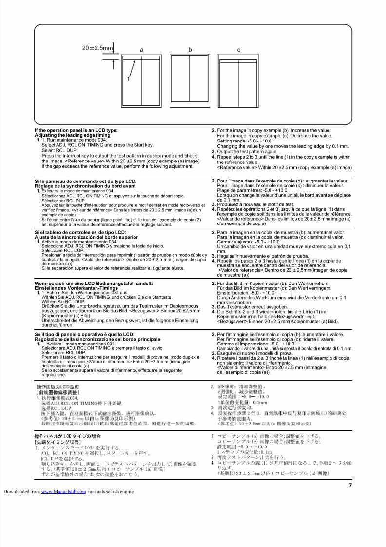
8/18/2019 taskalfa_220
http://slidepdf.com/reader/full/taskalfa220 294/3007
b ca
1
202.5mm
操作パネルが LCDタイプの場合
[先端タイミング調整]
1.メンテナンスモード U034を実行する。ADJ, RCL ON TIMING を選択し、スタートキーを押す。RCL DUP を選択する。割り込みキーを押し、両面モードでテストパターンを出力して、画像を確認する。〈基準値〉20± 2.5mm 以内(コピーサンプル (a)画像)ずれが基準値外の場合は、次の調整をおこなう。
2.コピーサンプル(b)画像の場合:調整値を上げる。コピーサンプル(c)画像の場合:調整値を下げる。設定範囲:-5.0 ~ +10.01 ステップの変化量:0.1mm
3.再度テストパターン出力を行う。4.コピーサンプルの線(1)が基準値内になるまで、手順2~ 3を繰
り返す。〈基準値〉20± 2.5mm 以内(コピーサンプル (a) 画像)
If the operation panel is an LCD type:Adjusting the leading edge timing1. 1. Run maintenance mode 034.
Select ADJ, RCL ON TIMING and press the Start key.Select RCL DUP.Press the Interrupt key to output the test pattern in duplex mode and checkthe image. <Reference value> Within 20 ±2.5 mm (copy example (a) image)If the gap exceeds the reference value, perform the following adjustment.
2. For the image in copy example (b): Increase the value.For the image in copy example (c): Decrease the value.Setting range: -5.0 - +10.0Changing the value by one moves the leading edge by 0.1 mm.
3. Output the test pattern again.4. Repeat steps 2 to 3 until the line (1) in the copy example is within
the reference value.<Reference value> Within 20 ±2.5 mm (copy example (a) image)
Si le panneau de commande est du type LCD:Réglage de la synchronisation du bord avant
1. Exécutez le mode de maintenance 034.Sélectionnez ADJ, RCL ON TIMING et appuyez sur la touche de départ copie.Sélectionnez RCL DUP. Appuyez sur la touche d'interruption pour produire le motif de test en mode recto-verso etvérifiez l'image. <Valeur de référence> Dans les limites de 20 ± 2,5 mm (image (a) d'unexemple de copie)Si l’écart entre l'axe du papier (ligne pointillée) et le trait de l'exemple de copie (2)est supérieur à la valeur de référence,effectuez le réglage suivant.
2. Pour l'image dans l'exemple de copie (b) : augmenter la valeur.Pour l'image dans l'exemple de copie (c) : diminuer la valeur.
Plage de paramètres: -5,0 - +10,0Lorsqu’on change la valeur d’une unité, le bord avant se déplacede 0,1 mm.
3. Produisez à nouveau le motif de test.4. Répétez les opérations 2 et 3 jusqu'à ce que la ligne (1) dans
l'exemple de copie soit dans les limites de la valeur de référence.<Valeur de référence> Dans les limites de 20 ± 2,5 mm(image (a)d'un exemple de copie)
Si el tablero de controles es de tipo LCD:Ajuste de la sincronización del borde superior 1. Active el modo de mantenimiento 034.
Seleccione ADJ, RCL ON TIMING y presione la tecla de inicio.Seleccione RCL DUP.Presionar la tecla de interrupción para imprimir el patrón de prueba en modo dúplex ycontrolar la imagen. <Valor de referencia> Dentro de 20 ± 2,5 mm (imagen de copiade muestra (a)).Si la separación supera el valor de referencia,realizar el siguiente ajuste.
2. Para la imagen en la copia de muestra (b): aumentar el valor.Para la imagen en la copia de muestra (c): disminuir el valor.Gama de ajustes: -5,0 - +10,0Un cambio de valor en una unidad mueve el extremo guía en 0,1mm.
3. Haga salir nuevamente el patrón de prueba.4. Repetir los pasos 2 a 3 hasta que la línea (1) en la copia de
muestra se encuentre dentro del valor de referencia. <Valor de referencia> Dentro de 20 ± 2,5mm(imagen de copiade muestra (a))
Wenn es sich um eine LCD-Bedienungstafel handelt:
Einstellen des Vorderkanten-Timings1. 1. Führen Sie den Wartungsmodus 034 aus.
Wählen Sie ADJ, RCL ON TIMING, und drücken Sie die Starttaste.Wählen Sie RCL DUP.Drücken Sie die Unterbrechungstaste, um das Testmuster im Duplexmodusauszugeben, und überprüfen Sie das Bild. <Bezugswert> Binnen 20 ±2,5 mm(Kopienmuster (a) Bild)Überschreitet die Abweichung den Bezugswert, ist die folgende Einstellungdurchzuführen.
2. Für das Bild im Kopienmuster (b): Den Wert erhöhen.
Für das Bild im Kopienmuster (c): Den Wert verringern.Einstellbereich: -5,0 - +10,0Durch Ändern des Werts um eins wird die Vorderkante um 0,1mm verschoben.
3. Das Testmuster erneut ausgeben.4. Die Schritte 2 und 3 wiederholen, bis die Linie (1) im
Kopienmuster innerhalb des Bezugswerts liegt.<Bezugswert> Binnen 20 ±2,5 mm(Kopienmuster (a) Bild).
Se il tipo di pannello operativo è quello LCD:Regolazione della sincronizzazione del bordo principale1. 1. Avviare il modo manutenzione 034.
Selezionare ADJ, RCL ON TIMING e premere il tasto di avvio.Selezionare RCL DUP.Premere il tasto di interruzione per eseguire i modelli di prova nel modo duplex econtrollare l’immagine. <Valore di rifer imento> Entro 20 ±2.5 mm (immaginedell'esempio di copia (a)Se lo scostamento supera il valore di riferimento, e ffettuare la seguenteregolazione.
2. Per l'immagine nell'esempio di copia (b): aumentare il valore.Per l'immagine nell'esempio di copia (c): ridurre il valore.Gamma di impostazione: -5.0 - +10.0Cambiando il valore di una unità si sposta il bordo di entrata di 0.1 mm.
3. Eseguire di nuovo i modelli di prova.4. Ripetere i passi da 2 a 3 finché la linea (1) nell'esempio di copia
non sia entro il valore di riferimento.<Valore di riferimento> Entro 20 ±2.5 mm (immaginedell'esempio di copia (a))
loaded from www.Manualslib.com manuals search engine
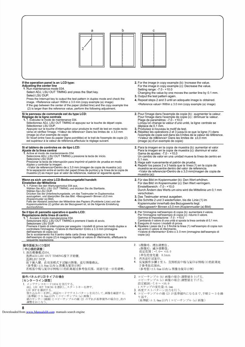
8/18/2019 taskalfa_220
http://slidepdf.com/reader/full/taskalfa220 295/3008
b ca
2
If the operation panel is an LCD type:Adjusting the center line1. Run maintenance mode 034.
Select ADJ, LSU OUT TIMING and press the Start key.Select LSU DUP.Press the Interrupt key to output the test pattern in duplex mode and check theimage. <Reference value> Within ± 3.0 mm (copy example (a) image)If the gap between the center of the paper (dotted line) and the copy example line (2) is larger than the reference value, perform the following adjustment.
2. For the image in copy example (b): Increase the value.For the image in copy example (c): Decrease the value.Setting range: -7.0 - +10.0Changing the value by one moves the center line by 0.1 mm.
3. Output the test pattern again.4. Repeat steps 2 and 3 until an adequate image is obtained.
<Reference value> Within ± 3.0 mm (copy example (a) image)
Si le panneau de commande est du type LCD:Réglage de la ligne centrale1. 1. Exécutez le mode de maintenance 034.
Sélectionnez ADJ, LSU OUT TIMING et appuyez sur la touche de départ copie.Sélectionnez LSU DUP. Appuyez sur la touche d'interruption pour produire le motif de test en mode recto-verso et vérifiez l'image. <Valeur de référence> Dans les limites de ± 3,0 mm(image (a) d'un exemple de copieSi l’écart entre l'axe du papier (ligne pointillée) et le trait de l'exemple de copie (2)est supérieur à la valeur de référence,effectuez le réglage suivant.
2. Pour l'image dans l'exemple de copie (b) : augmenter la valeur.Pour l'image dans l'exemple de copie (c) : diminuer la valeur.Plage de paramètres: -7,0 - +10,0Lorsqu’on change la valeur d’une unité, la ligne centrale sedéplace de 0,1 mm.
3. Produisez à nouveau le motif de test.4. Répétez les opérations 2 et 3 jusqu'à ce que la ligne (1) dans
l'exemple de copie soit dans les limites de la valeur de référence.<Valeur de référence> Dans les limites de ±3,0 mm(image (a) d'un exemple de copie)
Si el tablero de controles es de tipo LCD:Ajuste de la línea central1. Active el modo de mantenimiento 034.
Seleccione ADJ, LSU OUT TIMING y presione la tecla de inicio.Seleccione LSU DUP.Presionar la tecla de interrupción para imprimir el patrón de prueba en mododúplex y controlar la imagen. <Valor de referencia>Dentro de ± 3,0 mm (imagen de copia de muestra (a))Si la separación entre el centro del papel (línea de puntos) y la línea de la copia demuestra (2) es mayor que el valor de referencia, realizar el siguiente ajuste.
2. Para la imagen en la copia de muestra (b): aumentar el valor.Para la imagen en la copia de muestra (c): disminuir el valor.Gama de ajustes: -7,0 - +10,0Un cambio de valor en una unidad mueve la línea de centro en0,1 mm.
3. Haga salir nuevamente el patrón de prueba.4. Repetir los pasos 2 a 3 hasta que la línea (1) en la copia de
muestra se encuentre dentro del valor de referencia. <Valor de referencia>Dentro de ± 3,0 mm(imagen de copia demuestra (a))
Wenn es sich um eine LCD-Bedienungstafel handelt:
Einstellen der Mittellinie1. 1. Führen Sie den Wartungsmodus 034 aus.
Wählen Sie ADJ, LSU OUT TIMING, und drücken Sie die Starttaste.Wählen Sie LSU DUP.Drücken Sie die Unterbrechungstaste, um das Testmuster im Duplexmodusauszugeben, und überprüfen Sie das Bild. <Bezugswert> Binnen ±3,0 mm(Kopienmuster (a) Bild).Falls der Abstand zwischen der Mittenlinie des Papiers (Punktierte Linie) und derKopienmusterlinie (2) größer als der Bezugswert ist, ist die folgende Einstellungdurchzuführen.
2. Für das Bild im Kopienmuster (b): Den Wert erhöhen.
Für das Bild im Kopienmuster (c): Den Wert verringern.Einstellbereich: -7,0 - +10,0Durch Ändern des Werts um eins wird die Mittellinie um 0,1 mmverschoben.
3. Das Testmuster erneut ausgeben.4. Die Schritte 2 und 3 wiederholen, bis die Linie (1) im
Kopienmuster innerhalb des Bezugswerts liegt.<Bezugswert> Binnen ±3,0 mm (Kopienmuster (a) Bild)
Se il tipo di pannello operativo è quello LCD:Regolazione della linea di centro1. 1. Avviare il modo manutenzione 034.
Selezionare ADJ, LSU OUT TIMING e premere il tasto di avvio.Selezionare LSU DUP.Premere il tasto di interruzione per eseguire i modelli di prova nel modo duplex econtrollare l'immagine. <Valore di riferimento> Entro ± 3.0 mm (immaginedell'esempio di copia (a))Se lo scostamento fra il centro della carta (linea tratteggiata) e la lineadell'esempio di copia (2) è maggiore rispetto al valore di riferimento, effettuare laseguente regolazione.
2. Per l'immagine nell'esempio di copia (b): aumentare il valore.Per l'immagine nell'esempio di copia (c): ridurre il valore.Gamma di impostazione: -7.0 - +10.0Cambiando il valore di una unità si sposta la linea centrale di 0,1 mm.
3. Eseguire di nuovo i modelli di prova.4. Ripetere i passi da 2 a 3 finché la linea (1) nell'esempio di copia non
sia entro il valore di riferimento.<Valore di riferimento> Entro ± 3.0 mm (immagine dell'esempio dicopia (a))
操作パネルがLCDタイプの場合
[センターライン調整]1.メンテナンスモードU034を実行する。
ADJ, LSU OUT TIMING を選択し、スタートキーを押す。LSU DUPを選択する。割り込みキーを押し、両面モードでテストパターンを出力して、画像を確認する。
〈基準値〉±3.0mm以内 (コピーサンプル (a)画像)紙のセンター(破線)とコピーサンプルの線 (2) のずれが基準値外の場合は、次の調整をおこなう。
2.コピーサンプル(b)画像の場合:調整値を上げる。コピーサンプル(c)画像の場合:調整値を下げる。設定範囲:-7.0 ~ +10.01 ステップの変化量:0.1mm
3.再度テストパターン出力を行う。4.コピーサンプルの線(2)が基準値内になるまで、手順2~ 3を繰
り返す。〈基準値〉± 3.0mm以内(コピーサンプル (a)画像)
loaded from www.Manualslib.com manuals search engine

8/18/2019 taskalfa_220
http://slidepdf.com/reader/full/taskalfa220 296/300
INSTALLATION GUIDE FOR
Printing System (Z)
loaded from www.Manualslib.com manuals search engine
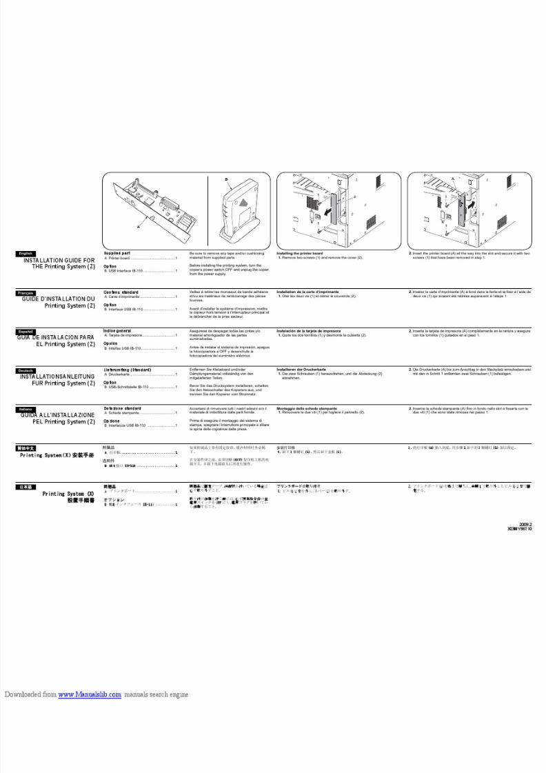
8/18/2019 taskalfa_220
http://slidepdf.com/reader/full/taskalfa220 297/300
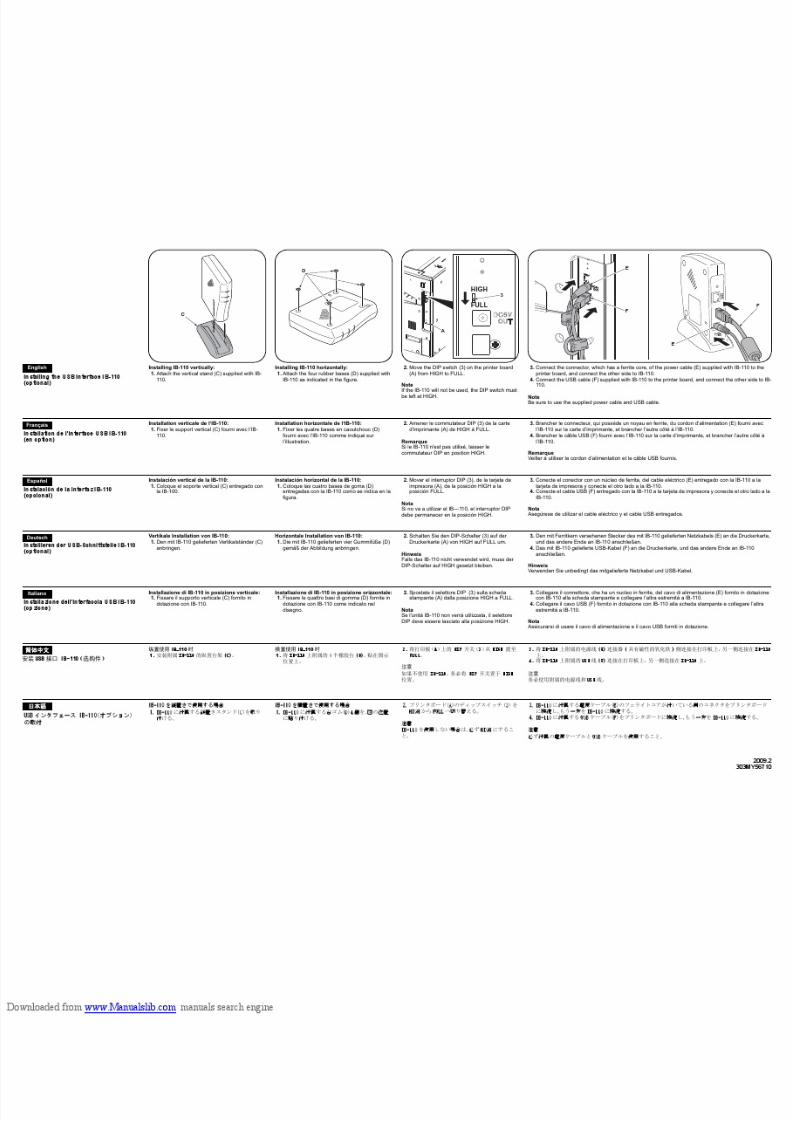
8/18/2019 taskalfa_220
http://slidepdf.com/reader/full/taskalfa220 298/300
8/18/2019 taskalfa_220
http://slidepdf.com/reader/full/taskalfa220 299/300
loaded from www.Manualslib.com manuals search engine
8/18/2019 taskalfa_220
http://slidepdf.com/reader/full/taskalfa220 300/300


