Embed Size (px)
Citation preview
Copyright 2008-2011 Hunter Engineering Company
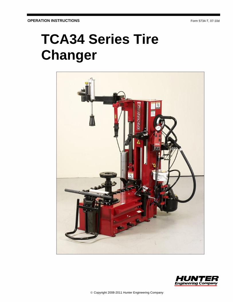
OPERATION INSTRUCTIONS Form 5734-T, 07-10d
TCA34 Series Tire Changer
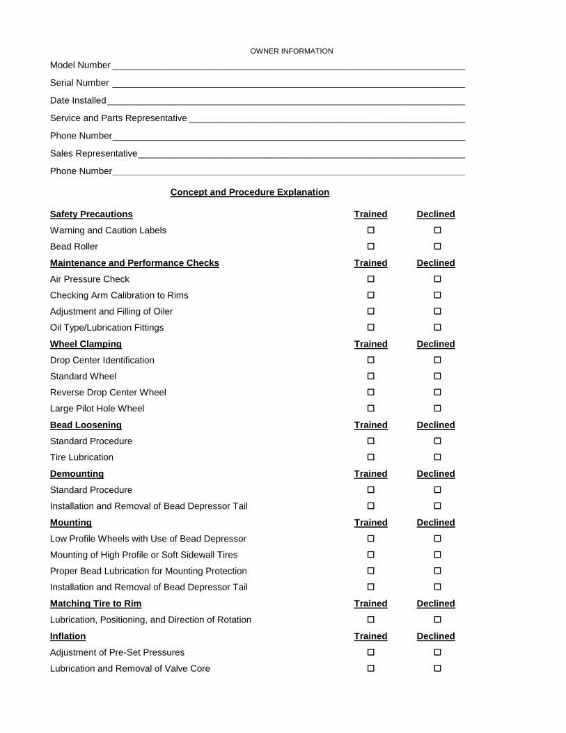
OWNER INFORMATION
Model Number _____________________________________________________________________
Serial Number _____________________________________________________________________
Date Installed ______________________________________________________________________
Service and Parts Representative ______________________________________________________
Phone Number _____________________________________________________________________
Sales Representative ________________________________________________________________
Phone Number _____________________________________________________________________
Concept and Procedure Explanation
Safety Precautions Trained Declined
Warning and Caution Labels
Bead Roller
Maintenance and Performance Checks Trained Declined
Air Pressure Check
Checking Arm Calibration to Rims
Adjustment and Filling of Oiler
Oil Type/Lubrication Fittings
Wheel Clamping Trained Declined
Drop Center Identification
Standard Wheel
Reverse Drop Center Wheel
Large Pilot Hole Wheel
Bead Loosening Trained Declined
Standard Procedure
Tire Lubrication
Demounting Trained Declined
Standard Procedure
Installation and Removal of Bead Depressor Tail
Mounting Trained Declined
Low Profile Wheels with Use of Bead Depressor
Mounting of High Profile or Soft Sidewall Tires
Proper Bead Lubrication for Mounting Protection
Installation and Removal of Bead Depressor Tail
Matching Tire to Rim Trained Declined
Lubrication, Positioning, and Direction of Rotation
Inflation Trained Declined
Adjustment of Pre-Set Pressures
Lubrication and Removal of Valve Core

Individuals and Date Trained
___________________________________ ___________________________________
___________________________________ ___________________________________
___________________________________ ___________________________________
___________________________________ ___________________________________
___________________________________ ___________________________________
___________________________________ ___________________________________
___________________________________ ___________________________________
___________________________________ ___________________________________
___________________________________ ___________________________________
___________________________________ ___________________________________
___________________________________ ___________________________________
___________________________________ ___________________________________
___________________________________ ___________________________________

TCA34 Series Tire Changer Operation Instructions Contents i
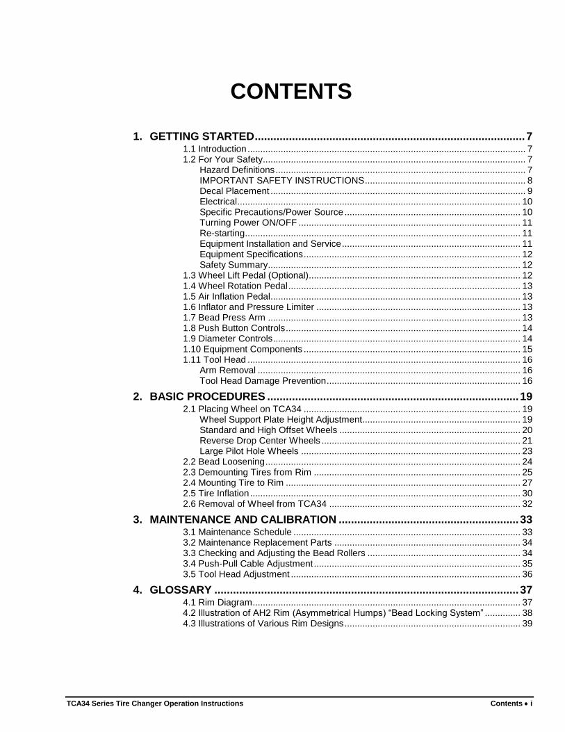
CONTENTS
1. GETTING STARTED ....................................................................................... 7 1.1 Introduction ............................................................................................................. 7 1.2 For Your Safety ....................................................................................................... 7
Hazard Definitions .................................................................................................. 7 IMPORTANT SAFETY INSTRUCTIONS ............................................................... 8 Decal Placement .................................................................................................... 9 Electrical ............................................................................................................... 10 Specific Precautions/Power Source ..................................................................... 10 Turning Power ON/OFF ....................................................................................... 11 Re-starting ............................................................................................................ 11 Equipment Installation and Service ...................................................................... 11 Equipment Specifications ..................................................................................... 12 Safety Summary ................................................................................................... 12
1.3 Wheel Lift Pedal (Optional) ................................................................................... 12 1.4 Wheel Rotation Pedal ........................................................................................... 13 1.5 Air Inflation Pedal .................................................................................................. 13 1.6 Inflator and Pressure Limiter ................................................................................ 13 1.7 Bead Press Arm ................................................................................................... 13 1.8 Push Button Controls ............................................................................................ 14 1.9 Diameter Controls ................................................................................................. 14 1.10 Equipment Components ..................................................................................... 15 1.11 Tool Head ........................................................................................................... 16
Arm Removal ....................................................................................................... 16 Tool Head Damage Prevention ............................................................................ 16
2. BASIC PROCEDURES ................................................................................. 19 2.1 Placing Wheel on TCA34 ..................................................................................... 19
Wheel Support Plate Height Adjustment .............................................................. 19 Standard and High Offset Wheels ....................................................................... 20 Reverse Drop Center Wheels .............................................................................. 21 Large Pilot Hole Wheels ...................................................................................... 23
2.2 Bead Loosening .................................................................................................... 24 2.3 Demounting Tires from Rim ................................................................................. 25 2.4 Mounting Tire to Rim ............................................................................................ 27 2.5 Tire Inflation .......................................................................................................... 30 2.6 Removal of Wheel from TCA34 ........................................................................... 32
3. MAINTENANCE AND CALIBRATION .......................................................... 33 3.1 Maintenance Schedule ......................................................................................... 33 3.2 Maintenance Replacement Parts ......................................................................... 34 3.3 Checking and Adjusting the Bead Rollers ............................................................ 34 3.4 Push-Pull Cable Adjustment ................................................................................. 35 3.5 Tool Head Adjustment .......................................................................................... 36
4. GLOSSARY .................................................................................................. 37 4.1 Rim Diagram ......................................................................................................... 37 4.2 Illustration of AH2 Rim (Asymmetrical Humps) “Bead Locking System” .............. 38 4.3 Illustrations of Various Rim Designs ..................................................................... 39

ii Contents TCA34 Series Tire Changer Operation Instructions
TCA34 Series Tire Changer Operation Instructions Getting Started 7
1. GETTING STARTED
1.1 Introduction
This manual provides operation instructions and information required to maintain the TCA34 series tire changer. A DVD video has been included to demonstrate advanced procedures.
The owner of the TCA34 is solely responsible for arranging technical training. The TCA34 is to be operated only by qualified trained technicians. Maintaining records of personnel trained is solely the responsibility of the owner and management.
This manual assumes the technician has already been trained in basic balancing procedures.
“References”
This manual assumes that you are already familiar with the basics of tire changing. The first section provides the basic information to operate the TCA34. The following sections contain detailed information about equipment, procedures, and maintenance. “Italics” are used to refer to specific parts of this manual that provide additional information or explanation. For example, refer to “Equipment Components,” page 15. These references should be read for additional information to the instructions being presented.
The owner of the TCA34 is solely responsible for arranging technical training. The TCA34 is to be operated only by a qualified trained technician. Maintaining records of personnel trained is solely the responsibility of the owner or management.
1.2 For Your Safety
Hazard Definitions
Watch for these symbols:
CAUTION: Hazards or unsafe practices, which could result in minor personal injury, or product or property damage.
WARNING: Hazards or unsafe practices, which could result in
severe personal injury or death.
DANGER: Immediate hazards, which will result in severe personal
injury or death.
These symbols identify situations that could be detrimental to your safety and/or cause equipment damage.
8 Getting Started TCA34 Series Tire Changer Operation Instructions
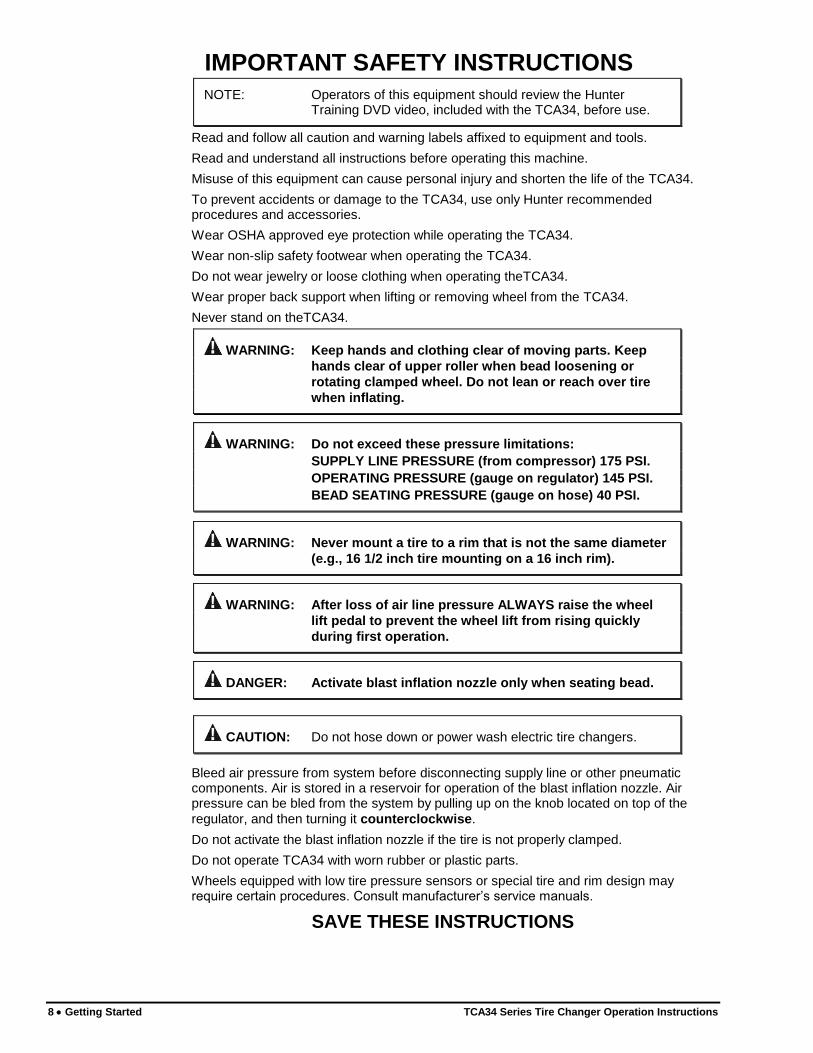
IMPORTANT SAFETY INSTRUCTIONS
NOTE: Operators of this equipment should review the Hunter Training DVD video, included with the TCA34, before use.
Read and follow all caution and warning labels affixed to equipment and tools.
Read and understand all instructions before operating this machine.
Misuse of this equipment can cause personal injury and shorten the life of the TCA34.
To prevent accidents or damage to the TCA34, use only Hunter recommended procedures and accessories.
Wear OSHA approved eye protection while operating the TCA34.
Wear non-slip safety footwear when operating the TCA34.
Do not wear jewelry or loose clothing when operating theTCA34.
Wear proper back support when lifting or removing wheel from the TCA34.
Never stand on theTCA34.
WARNING: Keep hands and clothing clear of moving parts. Keep
hands clear of upper roller when bead loosening or
rotating clamped wheel. Do not lean or reach over tire
when inflating.
WARNING: Do not exceed these pressure limitations:
SUPPLY LINE PRESSURE (from compressor) 175 PSI.
OPERATING PRESSURE (gauge on regulator) 145 PSI.
BEAD SEATING PRESSURE (gauge on hose) 40 PSI.
WARNING: Never mount a tire to a rim that is not the same diameter
(e.g., 16 1/2 inch tire mounting on a 16 inch rim).
WARNING: After loss of air line pressure ALWAYS raise the wheel
lift pedal to prevent the wheel lift from rising quickly
during first operation.
DANGER: Activate blast inflation nozzle only when seating bead.
CAUTION: Do not hose down or power wash electric tire changers.
Bleed air pressure from system before disconnecting supply line or other pneumatic components. Air is stored in a reservoir for operation of the blast inflation nozzle. Air pressure can be bled from the system by pulling up on the knob located on top of the
regulator, and then turning it counterclockwise.
Do not activate the blast inflation nozzle if the tire is not properly clamped.
Do not operate TCA34 with worn rubber or plastic parts.
Wheels equipped with low tire pressure sensors or special tire and rim design may require certain procedures. Consult manufacturer’s service manuals.
SAVE THESE INSTRUCTIONS
TCA34 Series Tire Changer Operation Instructions Getting Started 9
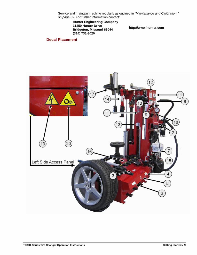
Service and maintain machine regularly as outlined in “Maintenance and Calibration,” on page 33. For further information contact:
Hunter Engineering Company
11250 Hunter Drive
Bridgeton, Missouri 63044
(314) 731-3020
http://www.hunter.com
Decal Placement
10 Getting Started TCA34 Series Tire Changer Operation Instructions
1 128-1174-2 DECAL-TCA34
2 128-1173-2 DECAL-TCA34 CONTROL PANEL
3 128-435-2 DECAL-REMOVE CLIP-ON WEIGHTS
4 RP6-3691 DECAL-INFLATION
5 RP6-710211210 DECAL-ROTATION
6 RP6-999916340 DECAL-LIFT
7 128-285-2 DECAL-WARNING PRESSURE LIMITATIONS
8 128-1149-2 DECAL-WARNING AIR BLAST
9 128-323-2 DECAL-EYE PROTECTION
10 128-485-2 DECAL-REVIEW VIDEO BEFORE USING
11 128-287-2 DECAL-WARNING INFLATION
12 128-284-2 DECAL-SAFETY INSTRUCTIONS
13 128-1213-2 DECAL-TCA TPMS SENSOR
14 128-1194-2 DECAL-ATTENTION TCA ARM
15 128-1242-2 (on reverse)
DECAL-TCA MOTOR RESET
16 128-1241-2 (under lower arm)
DECAL-KEEP CLEAR
17 RP6-1266 DECAL-HAND DANGER
18 128-501-2 DECAL-MANUAL BLEED VALVE
19 RP6-99990758 DECAL-VOLTAGE
20 RP6-4244 DECAL-GEARS
Electrical
The TCA34 is manufactured to operate at a specific voltage and amperage rating.
Make sure that the appropriate electrical supply circuit is of the same voltage and amperage ratings as marked on the TCA34.
WARNING: DO NOT ALTER THE ELECTRICAL PLUG. Plugging the
electrical plug into an unsuitable supply circuit will
damage the equipment.
Make sure that the electrical supply circuit and the appropriate receptacle is installed with proper grounding.
To prevent the possibility of electrical shock injury or damage to the equipment when servicing the TCA34, power must be disconnected by removing the power cord from the electrical power outlet.
After servicing, be sure the TCA34 ON/OFF switch is in the “O” (off) position before plugging the power cord into the electrical power outlet.
Specific Precautions/Power Source
The TCA34 is intended to operate from a power source that will apply 208-230VAC, 1 phase, 15 amp 50/60 Hz, power cable includes NEMA 20 amp plug, L6-20P, between the supply conductors of the power cord. The power cord supplied utilizes a twist lock connector, NEMA L6-20P. This machine must be connected to a 20 amp branch
TCA34 Series Tire Changer Operation Instructions Getting Started 11
circuit. Please refer all power source issues to a certified electrician. Refer to “Installation Instructions for TCA34 Tire Changer,” Form 5735-T.
CAUTION: A protective ground connection, through the grounding conductor in the power cord, is essential for safe operation. Use only a power cord that is in good condition.
NOTE: For information on converting from single phase NEMA L6-20P plug to thee phase NEMA L15-20P plug refer to Form 5350T, “NEMA L6-20P to NEMA L15-20P Power Plug Conversion Instructions.”
Turning Power ON/OFF
The ON/OFF switch is located on the back of the TCA34. To turn the TCA34 “ON,” press the “I” side of the ON/OFF switch. To turn the TCA34 “OFF,” press the “O” side of the ON/OFF switch.
IMPORTANT: After turning on the TCA34 the user must wait 30 seconds for the motor controller to “learn” the position of the rotation pedal before operating the tire changer.
Re-starting
If a rotation issue is encountered, re-start the tire changer using the following procedure:
1. Switch the tire changer power switch to the “off” position.
2. Wait 1 minute to discharge the drive system.
OR
Lift the rotation pedal (reverse) to discharge the drive system.
3. Do NOT touch the rotation pedal for 30 seconds. This will allow the pedal to “learn” its new position.
4. Operate the tire changer normally.
Equipment Installation and Service
A factory-authorized representative should perform installation.
This equipment contains no user serviceable parts. All repairs must be referred to a qualified Hunter Service Representative.
12 Getting Started TCA34 Series Tire Changer Operation Instructions
Equipment Specifications
Electrical
Voltage: 208-230VAC, 1 phase, 50/60 Hz, power cable includes NEMA 20 amp plug, L6-20P
Amperage: 15 amperes
Wattage: 3450 watts (peak)
Air
Air Pressure Requirements: 115-175 PSI (7.9-12.0 bar)
Approximate Air Consumption: 4 CFM (110 Liters/Minute)
Mechanical
Clamping System Rotating Speed:
CW – variable up to 15 rpm CCW – 7rpm
Torque: 867 ft-lbs
Max. Tire Diameter: 50 / 52 / 54 in.
Max Bead Roller Opening Width: 15 in.
Diameter Range: 10-30 / 12-32 / 14-34
Bead Roller Power; Each Roller: 2645 lbs.
Safety Summary
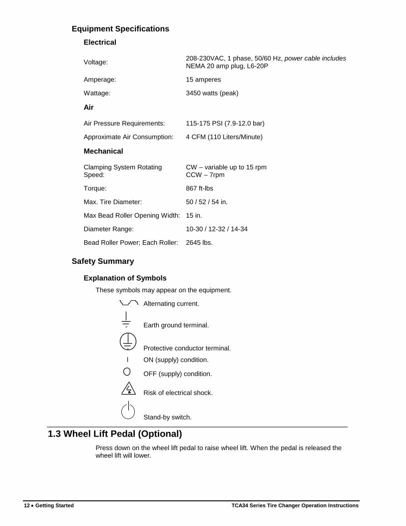
Explanation of Symbols
These symbols may appear on the equipment.
Alternating current.
Earth ground terminal.
Protective conductor terminal.
l ON (supply) condition.
OFF (supply) condition.
Risk of electrical shock.
Stand-by switch.
1.3 Wheel Lift Pedal (Optional)
Press down on the wheel lift pedal to raise wheel lift. When the pedal is released the wheel lift will lower.
TCA34 Series Tire Changer Operation Instructions Getting Started 13
CAUTION: The wheel lift may rise quickly during the first operation after loss of air line pressure. This can be mitigated by first lifting on wheel lift pedal before pressing down to operate wheel lift.
1.4 Wheel Rotation Pedal
The middle pedal on the TCA34 base controls the rotation of the wheel. Refer to “Equipment Components,” on page 15.
Step down on the pedal to rotate the wheel clockwise (variable speed).
Lift the pedal to rotate the wheel counterclockwise (fixed speed).
CAUTION: Keep hands clear of wheel, tire, and rollers during bead loosening.
1.5 Air Inflation Pedal
The right-hand pedal on the TCA34 base is a two-stage design. Refer to “Equipment Components,” on page 15. The pedal controls the air going to the inflation hose and the blast inflation nozzle.
CAUTION: Keep hands clear of wheel during sealing and seating of bead.
CAUTION: When operating air inflation hose, do not lean over the tire.
Step down partially on the pedal to inflate tires through inflation hose.
Step down completely on the pedal to activate the blast inflator nozzle to seal tire beads.
Refer to “2.5 Tire Inflation,“ on page 30 for complete inflation operation instructions.
1.6 Inflator and Pressure Limiter
As a safety device, the pressure limiter prevents the operator from using excessive air pressure to seat the tire bead during tire inflation. Bead seating pressure should never exceed 40 psi. If tires being mounted require more than 40 psi for inflation pressure, the tire/wheel assembly should be removed from the tire changer, placed in an inflation cage, and inflated per manufacturer’s instructions.
While inflating the tire, the pressure gauge will read zero until the inflation pedal is released. At that time, the gauge will give the correct air pressure reading in the tire.
Refer to “2.5 Tire Inflation,“ on page 30 for complete inflation operation instructions.
1.7 Bead Press Arm
The bead press arm assists with tire mounting. The bead press arm moves in tandem with the mount / demount head.
The controls on the bead press arm move the bead press up or down.
Refer to “Equipment Components,” on page 15.
14 Getting Started TCA34 Series Tire Changer Operation Instructions
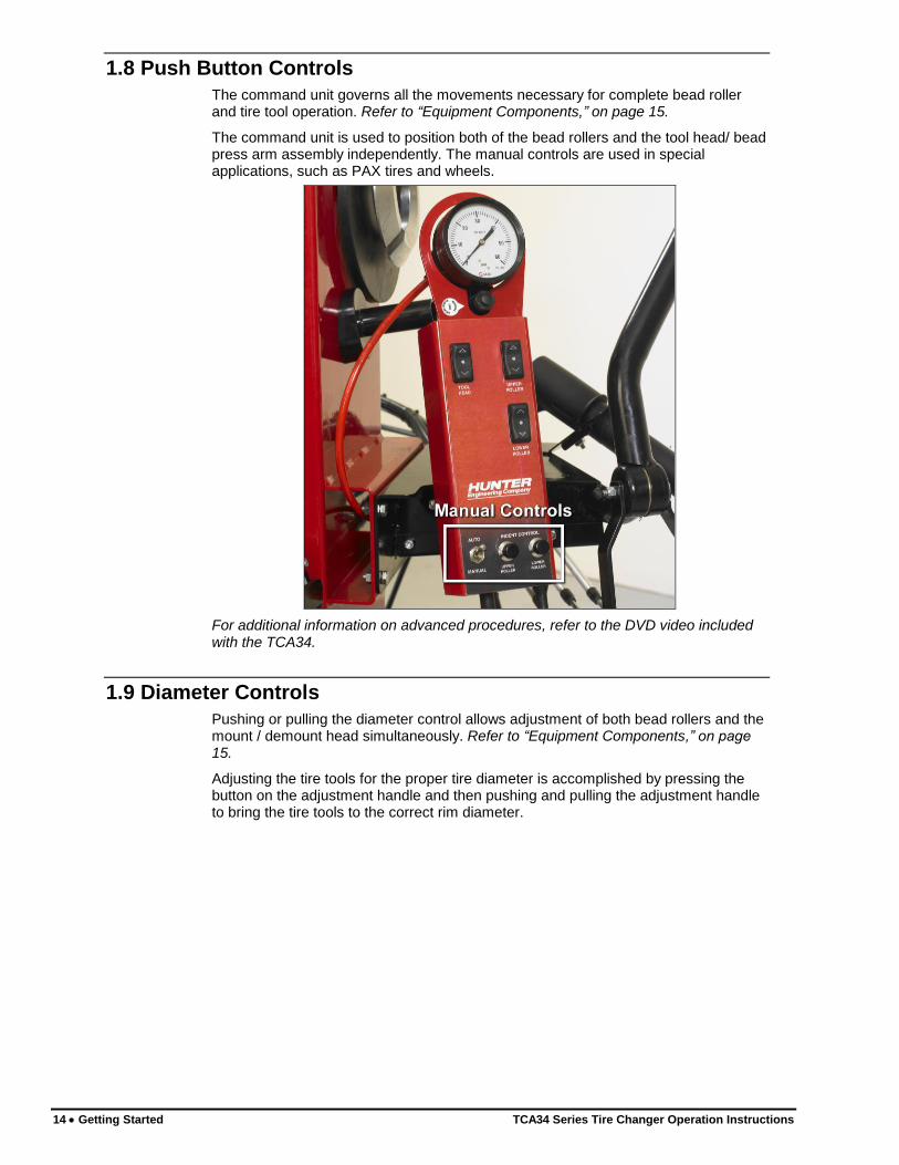
1.8 Push Button Controls
The command unit governs all the movements necessary for complete bead roller and tire tool operation. Refer to “Equipment Components,” on page 15.
The command unit is used to position both of the bead rollers and the tool head/ bead press arm assembly independently. The manual controls are used in special applications, such as PAX tires and wheels.
For additional information on advanced procedures, refer to the DVD video included with the TCA34.
1.9 Diameter Controls
Pushing or pulling the diameter control allows adjustment of both bead rollers and the mount / demount head simultaneously. Refer to “Equipment Components,” on page 15.
Adjusting the tire tools for the proper tire diameter is accomplished by pressing the button on the adjustment handle and then pushing and pulling the adjustment handle to bring the tire tools to the correct rim diameter.
TCA34 Series Tire Changer Operation Instructions Getting Started 15
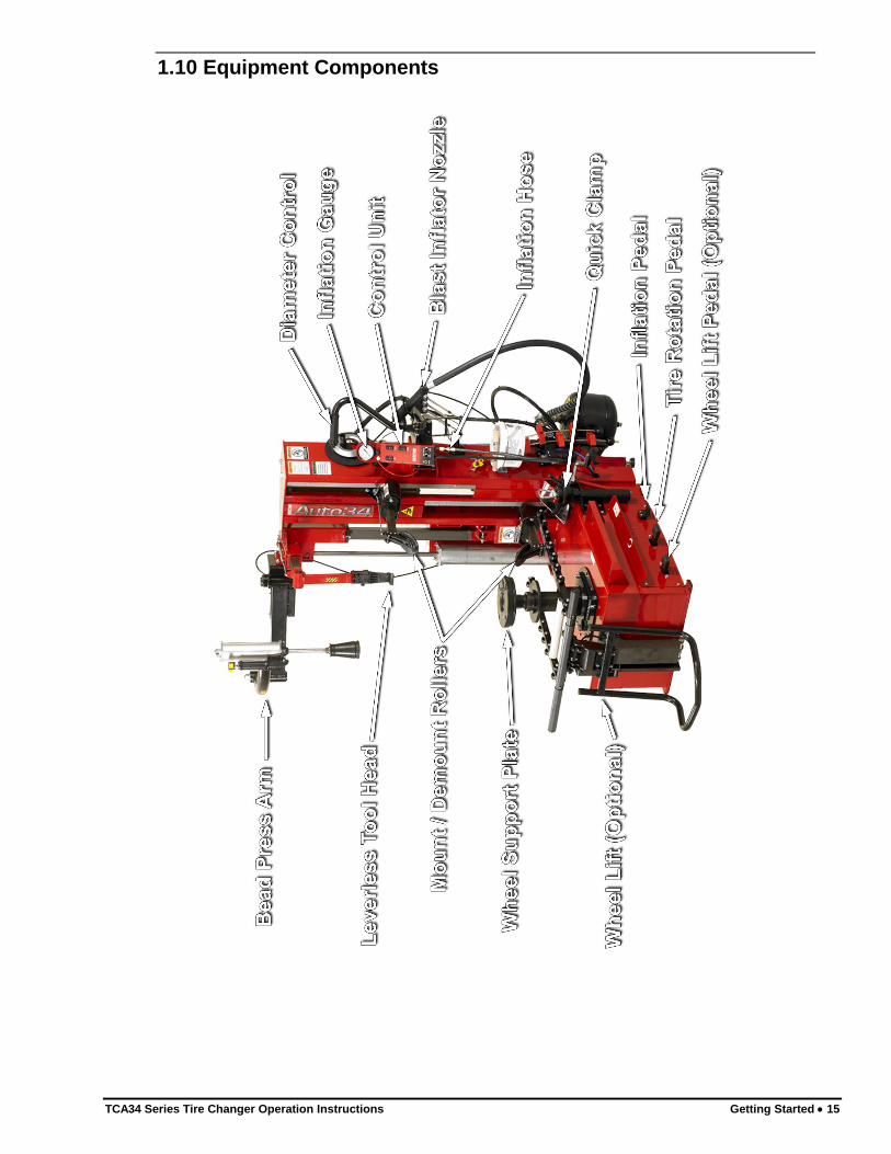
1.10 Equipment Components
16 Getting Started TCA34 Series Tire Changer Operation Instructions
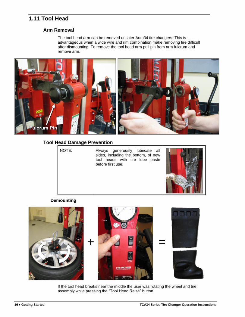
1.11 Tool Head
Arm Removal
The tool head arm can be removed on later Auto34 tire changers. This is advantageous when a wide wire and rim combination make removing tire difficult after dismounting. To remove the tool head arm pull pin from arm fulcrum and remove arm.
Tool Head Damage Prevention
NOTE: Always generously lubricate all sides, including the bottom, of new tool heads with tire lube paste before first use.
Demounting
If the tool head breaks near the middle the user was rotating the wheel and tire assembly while pressing the “Tool Head Raise” button.
TCA34 Series Tire Changer Operation Instructions Getting Started 17
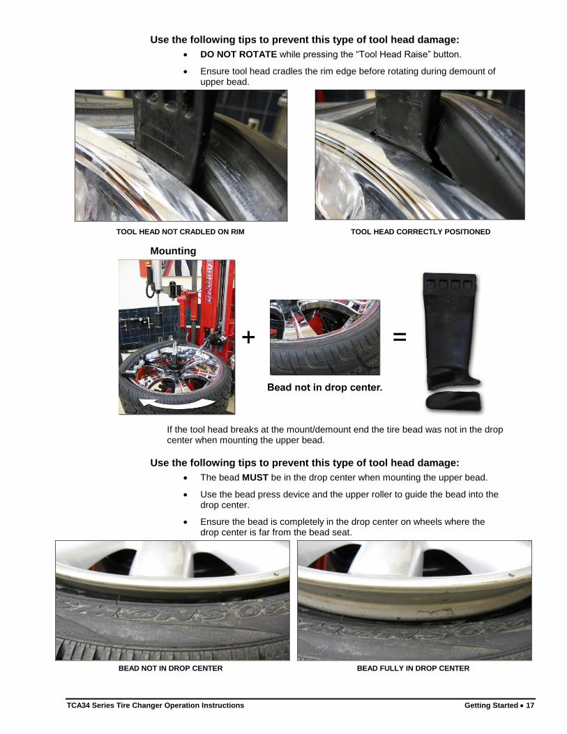
Use the following tips to prevent this type of tool head damage:
DO NOT ROTATE while pressing the “Tool Head Raise” button.
Ensure tool head cradles the rim edge before rotating during demount of upper bead.
TOOL HEAD NOT CRADLED ON RIM TOOL HEAD CORRECTLY POSITIONED
Mounting
If the tool head breaks at the mount/demount end the tire bead was not in the drop center when mounting the upper bead.
Use the following tips to prevent this type of tool head damage:
The bead MUST be in the drop center when mounting the upper bead.
Use the bead press device and the upper roller to guide the bead into the drop center.
Ensure the bead is completely in the drop center on wheels where the drop center is far from the bead seat.
BEAD NOT IN DROP CENTER BEAD FULLY IN DROP CENTER

TCA34 Series Tire Changer Operation Instructions Basic Procedures 19
2. BASIC PROCEDURES
2.1 Placing Wheel on TCA34
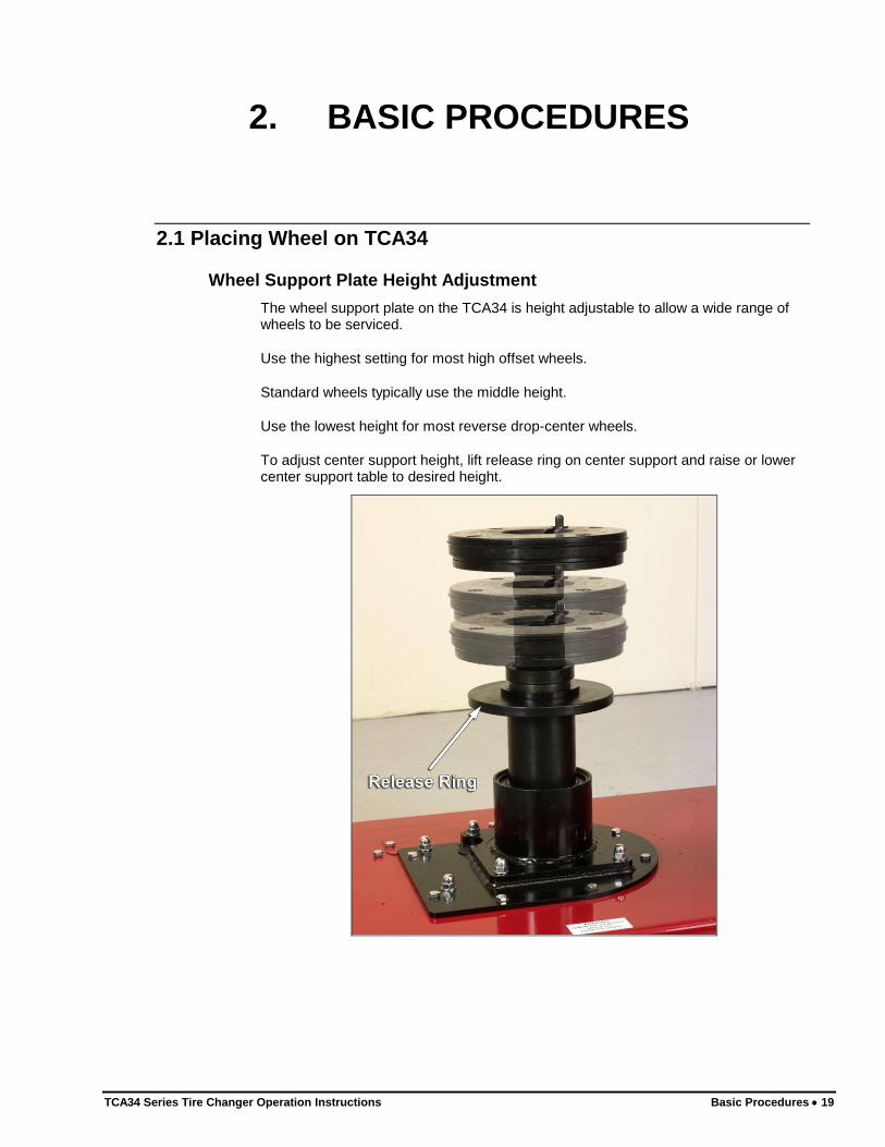
Wheel Support Plate Height Adjustment
The wheel support plate on the TCA34 is height adjustable to allow a wide range of wheels to be serviced.
Use the highest setting for most high offset wheels.
Standard wheels typically use the middle height.
Use the lowest height for most reverse drop-center wheels.
To adjust center support height, lift release ring on center support and raise or lower center support table to desired height.
20 Basic Procedures TCA34 Series Tire Changer Operation Instructions
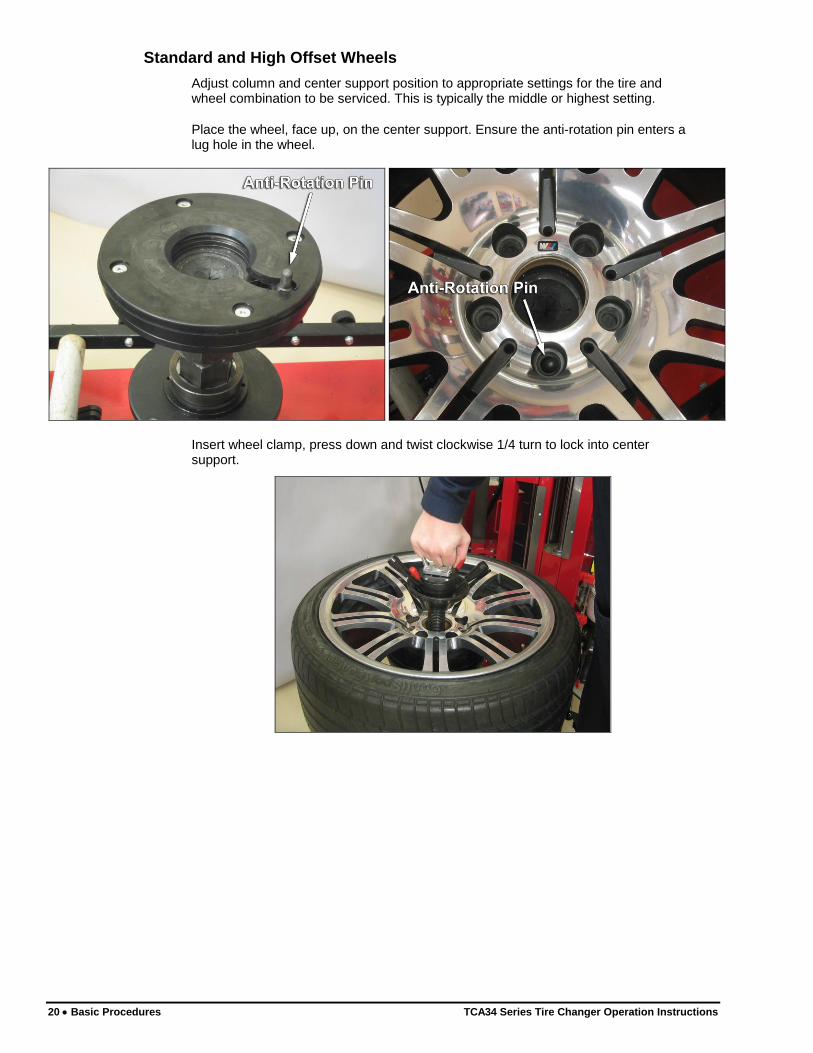
Standard and High Offset Wheels
Adjust column and center support position to appropriate settings for the tire and wheel combination to be serviced. This is typically the middle or highest setting.
Place the wheel, face up, on the center support. Ensure the anti-rotation pin enters a lug hole in the wheel.
Insert wheel clamp, press down and twist clockwise 1/4 turn to lock into center support.
TCA34 Series Tire Changer Operation Instructions Basic Procedures 21
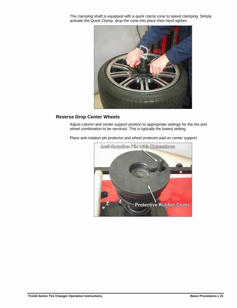
The clamping shaft is equipped with a quick clamp cone to speed clamping. Simply activate the Quick Clamp, drop the cone into place then hand tighten.
Reverse Drop Center Wheels
Adjust column and center support position to appropriate settings for the tire and wheel combination to be serviced. This is typically the lowest setting.
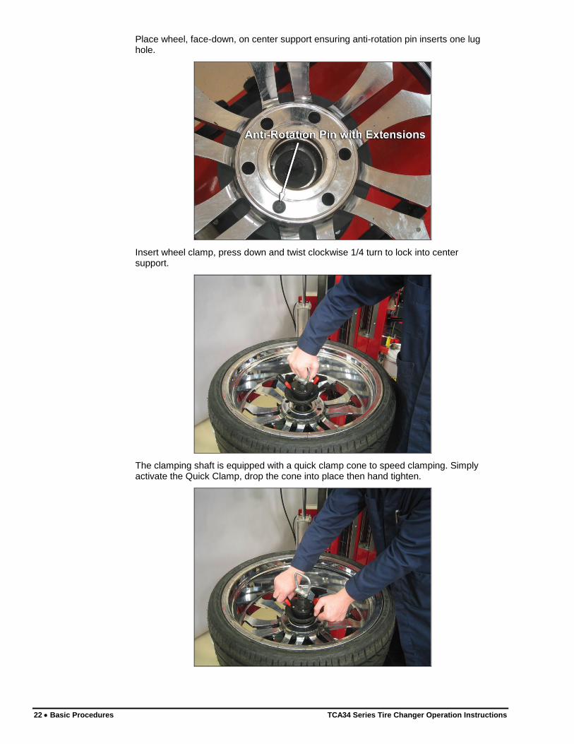
Place anti-rotation pin protector and wheel protector pad on center support
22 Basic Procedures TCA34 Series Tire Changer Operation Instructions
Place wheel, face-down, on center support ensuring anti-rotation pin inserts one lug hole.
Insert wheel clamp, press down and twist clockwise 1/4 turn to lock into center support.
The clamping shaft is equipped with a quick clamp cone to speed clamping. Simply activate the Quick Clamp, drop the cone into place then hand tighten.
TCA34 Series Tire Changer Operation Instructions Basic Procedures 23
Large Pilot Hole Wheels
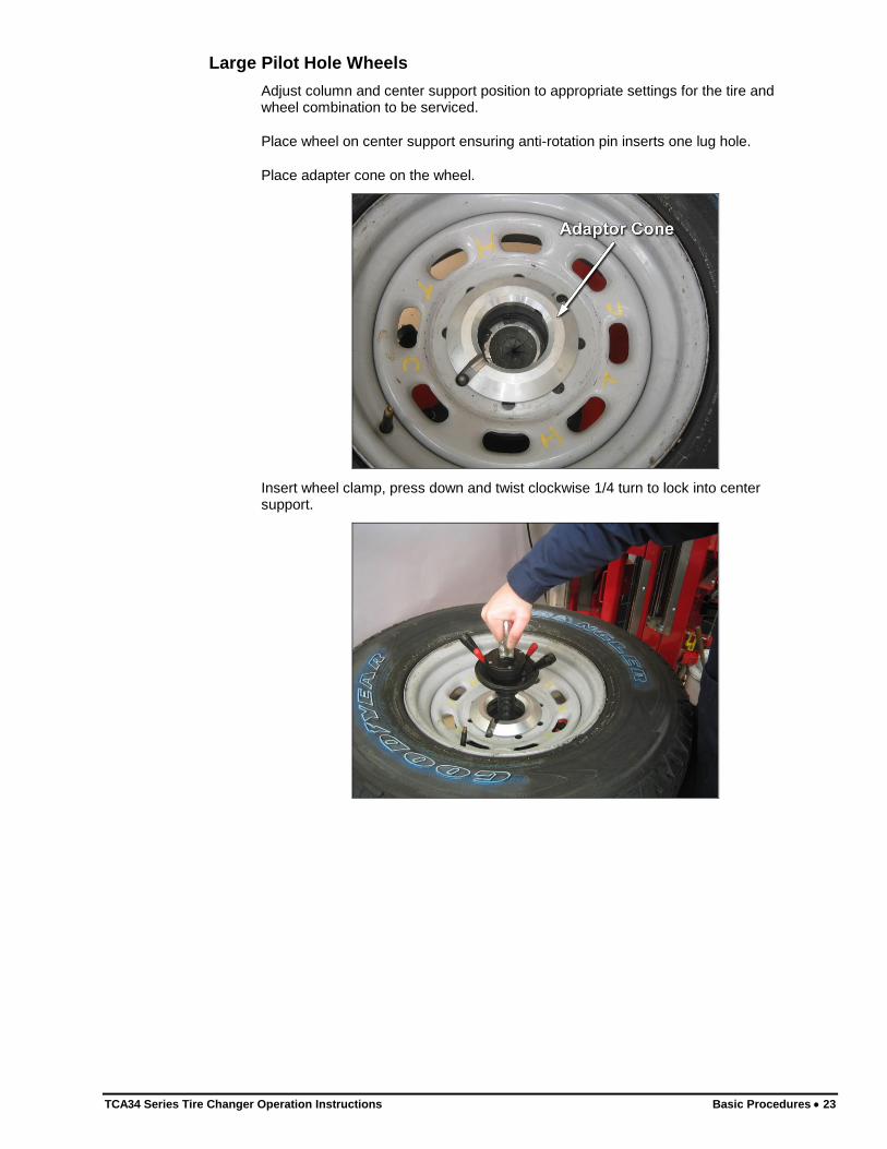
Adjust column and center support position to appropriate settings for the tire and wheel combination to be serviced.
Place wheel on center support ensuring anti-rotation pin inserts one lug hole.
Place adapter cone on the wheel.
Insert wheel clamp, press down and twist clockwise 1/4 turn to lock into center support.
24 Basic Procedures TCA34 Series Tire Changer Operation Instructions
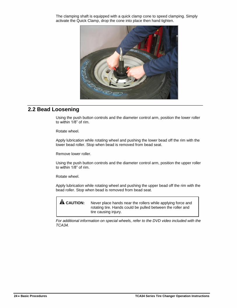
The clamping shaft is equipped with a quick clamp cone to speed clamping. Simply activate the Quick Clamp, drop the cone into place then hand tighten.
2.2 Bead Loosening
Using the push button controls and the diameter control arm, position the lower roller to within 1/8” of rim.
Rotate wheel.
Apply lubrication while rotating wheel and pushing the lower bead off the rim with the lower bead roller. Stop when bead is removed from bead seat.
Remove lower roller.
Using the push button controls and the diameter control arm, position the upper roller to within 1/8” of rim.
Rotate wheel.
Apply lubrication while rotating wheel and pushing the upper bead off the rim with the bead roller. Stop when bead is removed from bead seat.
CAUTION: Never place hands near the rollers while applying force and rotating tire. Hands could be pulled between the roller and tire causing injury.
For additional information on special wheels, refer to the DVD video included with the TCA34.
TCA34 Series Tire Changer Operation Instructions Basic Procedures 25
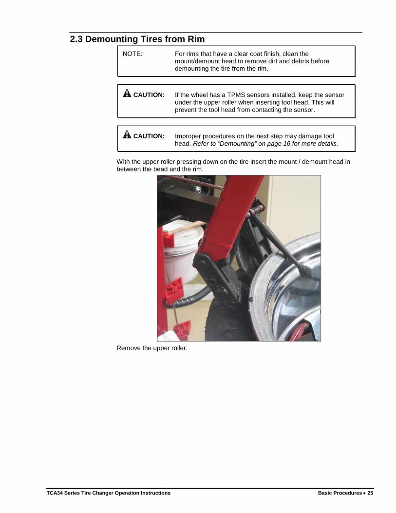
2.3 Demounting Tires from Rim
NOTE: For rims that have a clear coat finish, clean the mount/demount head to remove dirt and debris before demounting the tire from the rim.
CAUTION: If the wheel has a TPMS sensors installed, keep the sensor under the upper roller when inserting tool head. This will prevent the tool head from contacting the sensor.
CAUTION: Improper procedures on the next step may damage tool head. Refer to “Demounting” on page 16 for more details.
With the upper roller pressing down on the tire insert the mount / demount head in between the bead and the rim.
Remove the upper roller.
26 Basic Procedures TCA34 Series Tire Changer Operation Instructions
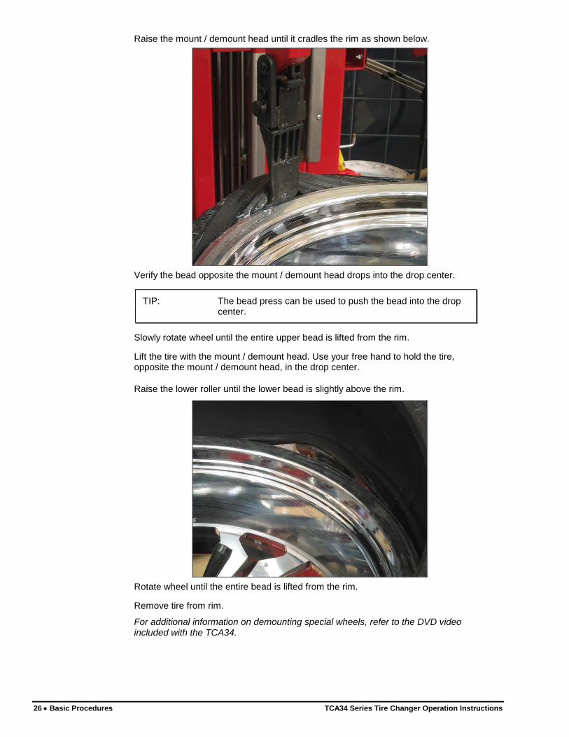
Raise the mount / demount head until it cradles the rim as shown below.
Verify the bead opposite the mount / demount head drops into the drop center.
TIP: The bead press can be used to push the bead into the drop center.
Slowly rotate wheel until the entire upper bead is lifted from the rim.
Lift the tire with the mount / demount head. Use your free hand to hold the tire, opposite the mount / demount head, in the drop center.
Raise the lower roller until the lower bead is slightly above the rim.
Rotate wheel until the entire bead is lifted from the rim.
Remove tire from rim.
For additional information on demounting special wheels, refer to the DVD video included with the TCA34.
TCA34 Series Tire Changer Operation Instructions Basic Procedures 27
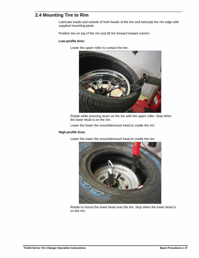
2.4 Mounting Tire to Rim
Lubricate inside and outside of both beads of the tire and lubricate the rim edge with supplied mounting paste.
Position tire on top of the rim and tilt tire forward toward column.
Low-profile tires:
Lower the upper roller to contact the tire.
Rotate while pressing down on the tire with the upper roller. Stop when the lower bead is on the rim.
Lower the lower the mount/demount head to cradle the rim.
High-profile tires:
Lower the lower the mount/demount head to cradle the rim.
Rotate to mount the lower bead onto the tire. Stop when the lower bead is on the rim.
28 Basic Procedures TCA34 Series Tire Changer Operation Instructions
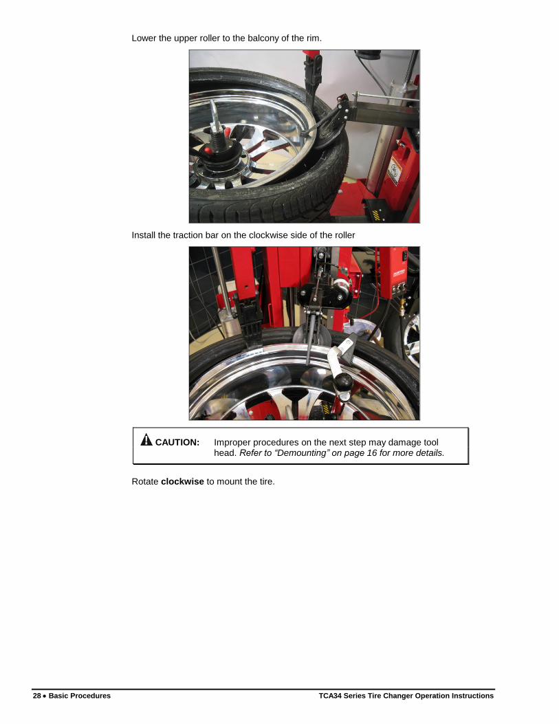
Lower the upper roller to the balcony of the rim.
Install the traction bar on the clockwise side of the roller
CAUTION: Improper procedures on the next step may damage tool head. Refer to “Demounting” on page 16 for more details.
Rotate clockwise to mount the tire.
TCA34 Series Tire Changer Operation Instructions Basic Procedures 29
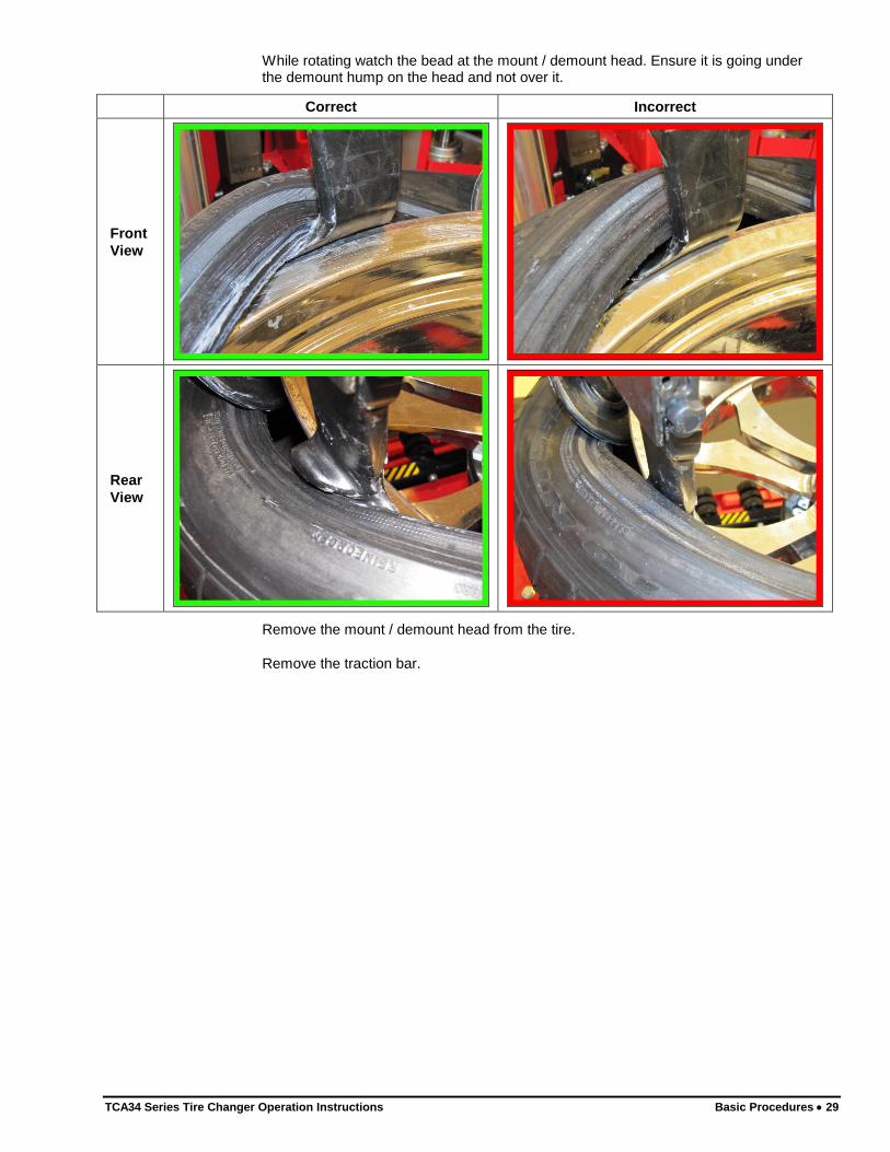
While rotating watch the bead at the mount / demount head. Ensure it is going under the demount hump on the head and not over it.
Correct Incorrect
Front
View
Rear
View
Remove the mount / demount head from the tire.
Remove the traction bar.
30 Basic Procedures TCA34 Series Tire Changer Operation Instructions
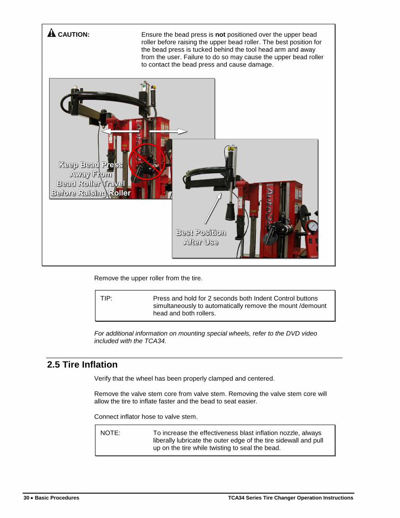
CAUTION: Ensure the bead press is not positioned over the upper bead roller before raising the upper bead roller. The best position for the bead press is tucked behind the tool head arm and away from the user. Failure to do so may cause the upper bead roller to contact the bead press and cause damage.
Remove the upper roller from the tire.
TIP: Press and hold for 2 seconds both Indent Control buttons simultaneously to automatically remove the mount /demount head and both rollers.
For additional information on mounting special wheels, refer to the DVD video included with the TCA34.
2.5 Tire Inflation
Verify that the wheel has been properly clamped and centered.
Remove the valve stem core from valve stem. Removing the valve stem core will allow the tire to inflate faster and the bead to seat easier.
Connect inflator hose to valve stem.
NOTE: To increase the effectiveness blast inflation nozzle, always liberally lubricate the outer edge of the tire sidewall and pull up on the tire while twisting to seal the bead.
TCA34 Series Tire Changer Operation Instructions Basic Procedures 31
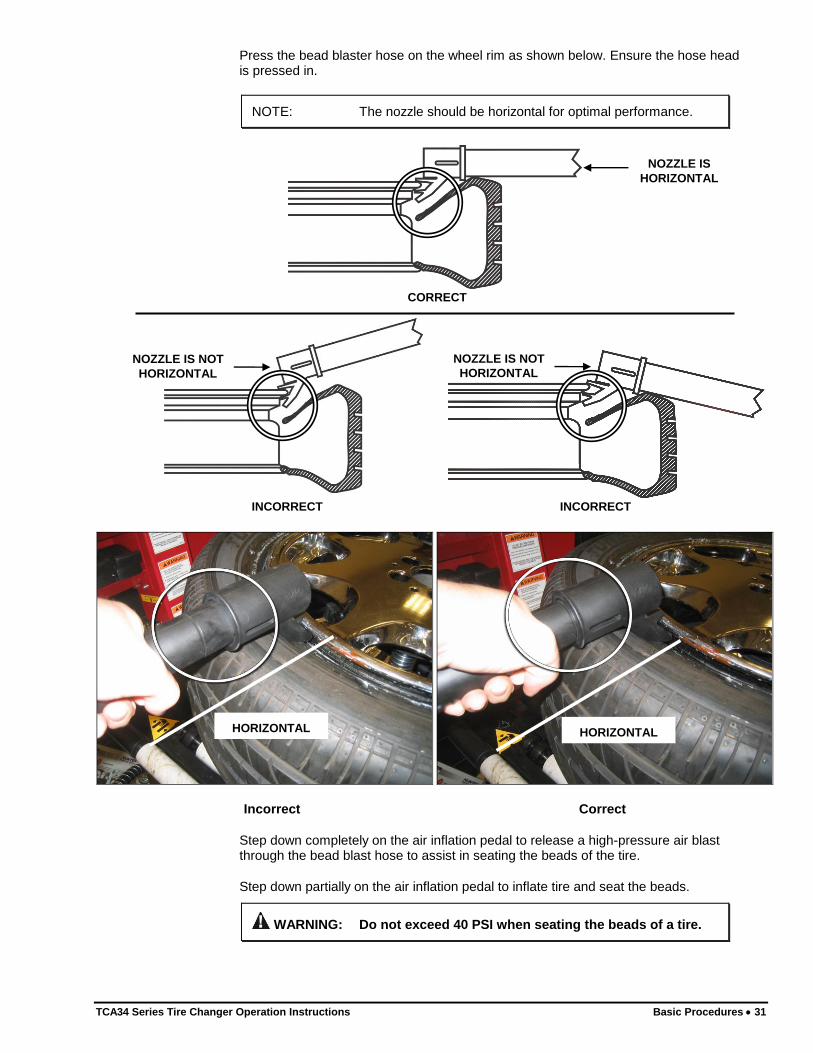
Press the bead blaster hose on the wheel rim as shown below. Ensure the hose head is pressed in.
NOTE: The nozzle should be horizontal for optimal performance.
CORRECT
INCORRECT
NOZZLE IS
HORIZONTAL
INCORRECT
NOZZLE IS NOT
HORIZONTAL
NOZZLE IS NOT
HORIZONTAL
Incorrect Correct
Step down completely on the air inflation pedal to release a high-pressure air blast through the bead blast hose to assist in seating the beads of the tire.
Step down partially on the air inflation pedal to inflate tire and seat the beads.
WARNING: Do not exceed 40 PSI when seating the beads of a tire.
HORIZONTAL HORIZONTAL
32 Basic Procedures TCA34 Series Tire Changer Operation Instructions
After beads have been seated, disconnect inflation hose and reinstall valve stem core previously removed. Then connect inflation hose and inflate tire to the required pressure.
If tire is over inflated, air may be removed from the tire by pressing the manual air release button located below the air pressure gauge.
Disconnect inflator hose from valve stem.
2.6 Removal of Wheel from TCA34
Loosen clamping cone.
Press down quick clamp and turn counter-clockwise to unlock clamp from center support. Remove wheel clamp.
Remove wheel from center support.
If applicable, remove anti-rotation pin extensions and wheel protector pad from center support.
TCA34 Series Tire Changer Operation Instructions Maintenance and Calibration 33
3. MAINTENANCE AND CALIBRATION
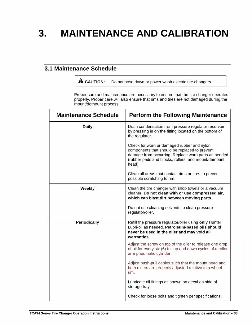
3.1 Maintenance Schedule
CAUTION: Do not hose down or power wash electric tire changers.
Proper care and maintenance are necessary to ensure that the tire changer operates properly. Proper care will also ensure that rims and tires are not damaged during the mount/demount process.
Maintenance Schedule Perform the Following Maintenance
Daily Drain condensation from pressure regulator reservoir by pressing in on the fitting located on the bottom of the regulator.
Check for worn or damaged rubber and nylon components that should be replaced to prevent damage from occurring. Replace worn parts as needed (rubber pads and blocks, rollers, and mount/demount head).
Clean all areas that contact rims or tires to prevent possible scratching to rim.
Weekly Clean the tire changer with shop towels or a vacuum
cleaner. Do not clean with or use compressed air,
which can blast dirt between moving parts.
Do not use cleaning solvents to clean pressure regulator/oiler.
Periodically Refill the pressure regulator/oiler using only Hunter
Lubri-oil as needed. Petroleum-based oils should
never be used in the oiler and may void all
warranties.
Adjust the screw on top of the oiler to release one drop of oil for every six (6) full up and down cycles of a roller arm pneumatic cylinder.
Adjust push-pull cables such that the mount head and both rollers are properly adjusted relative to a wheel rim.
Lubricate oil fittings as shown on decal on side of storage tray.
Check for loose bolts and tighten per specifications.
34 Maintenance and Calibration TCA34 Series Tire Changer Operation Instructions
3.2 Maintenance Replacement Parts QTY NAME NUMBER
1 Safety Goggles 179-15-2
1 Brush RP6-1506
1 Mounting Paste RP6-3784
1 Mount/Demount Head RP6-710011940
1 Rubber Protector Pad RP6-710013421
1 Quick Clamp Plastic Cone RP6-1156000
1 Pin Protector RP6-710090480
1 Pin Extension RP6-710012940
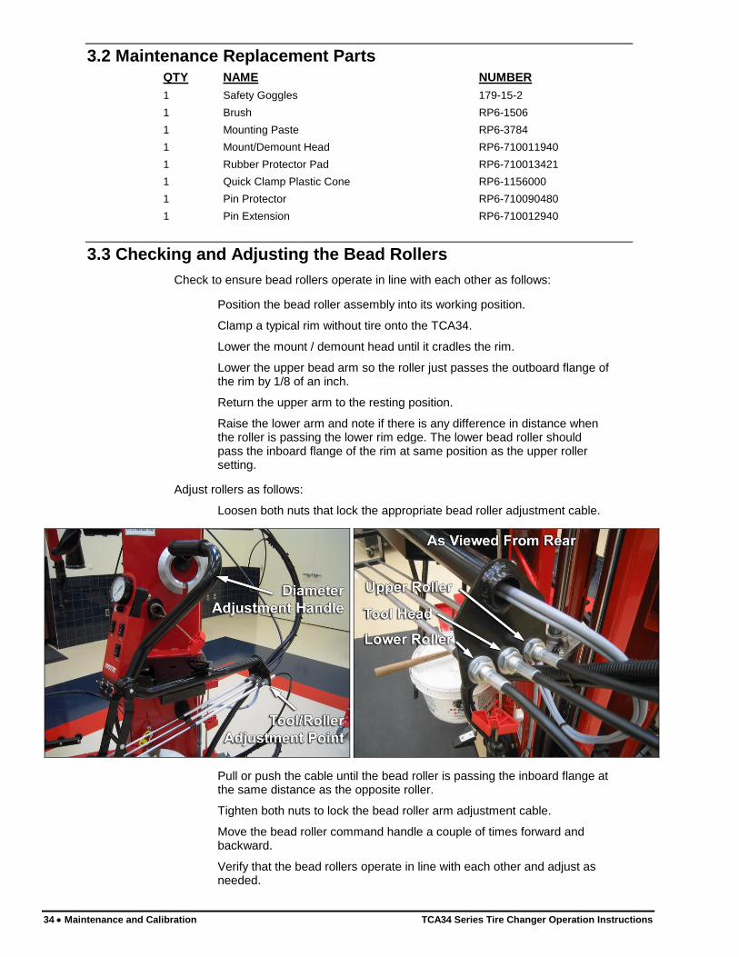
3.3 Checking and Adjusting the Bead Rollers
Check to ensure bead rollers operate in line with each other as follows:
Position the bead roller assembly into its working position.
Clamp a typical rim without tire onto the TCA34.
Lower the mount / demount head until it cradles the rim.
Lower the upper bead arm so the roller just passes the outboard flange of the rim by 1/8 of an inch.
Return the upper arm to the resting position.
Raise the lower arm and note if there is any difference in distance when the roller is passing the lower rim edge. The lower bead roller should pass the inboard flange of the rim at same position as the upper roller setting.
Adjust rollers as follows:
Loosen both nuts that lock the appropriate bead roller adjustment cable.
Pull or push the cable until the bead roller is passing the inboard flange at the same distance as the opposite roller.
Tighten both nuts to lock the bead roller arm adjustment cable.
Move the bead roller command handle a couple of times forward and backward.
Verify that the bead rollers operate in line with each other and adjust as needed.
TCA34 Series Tire Changer Operation Instructions Maintenance and Calibration 35
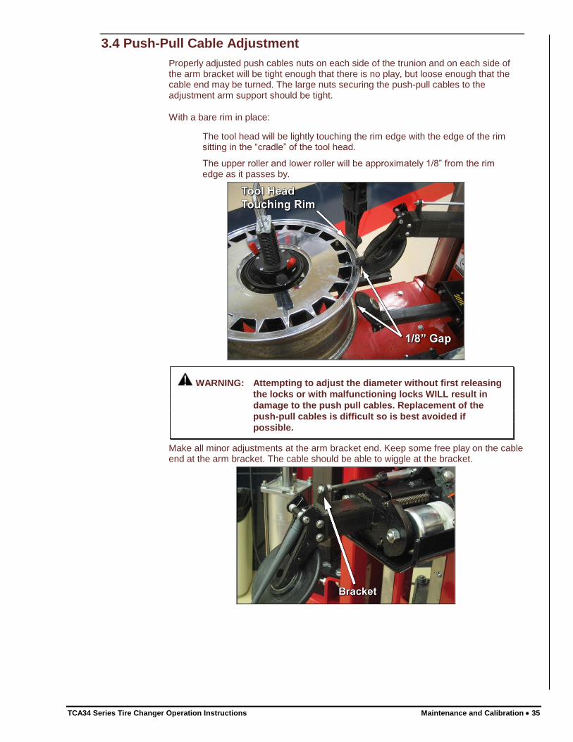
3.4 Push-Pull Cable Adjustment
Properly adjusted push cables nuts on each side of the trunion and on each side of the arm bracket will be tight enough that there is no play, but loose enough that the cable end may be turned. The large nuts securing the push-pull cables to the adjustment arm support should be tight.
With a bare rim in place:
The tool head will be lightly touching the rim edge with the edge of the rim sitting in the “cradle” of the tool head.
The upper roller and lower roller will be approximately 1/8” from the rim edge as it passes by.
WARNING: Attempting to adjust the diameter without first releasing
the locks or with malfunctioning locks WILL result in
damage to the push pull cables. Replacement of the
push-pull cables is difficult so is best avoided if
possible.
Make all minor adjustments at the arm bracket end. Keep some free play on the cable end at the arm bracket. The cable should be able to wiggle at the bracket.
36 Maintenance and Calibration TCA34 Series Tire Changer Operation Instructions
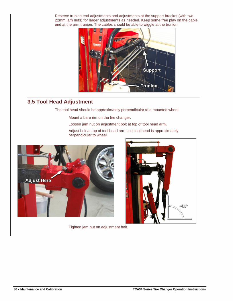
Reserve trunion end adjustments and adjustments at the support bracket (with two 22mm jam nuts) for larger adjustments as needed. Keep some free play on the cable end at the arm trunion. The cables should be able to wiggle at the trunion.
3.5 Tool Head Adjustment
The tool head should be approximately perpendicular to a mounted wheel.
Mount a bare rim on the tire changer.
Loosen jam nut on adjustment bolt at top of tool head arm.
Adjust bolt at top of tool head arm until tool head is approximately perpendicular to wheel.
Tighten jam nut on adjustment bolt.
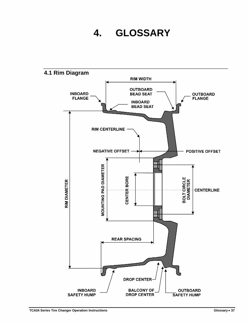
TCA34 Series Tire Changer Operation Instructions Glossary 37
4. GLOSSARY
4.1 Rim Diagram
38 Glossary TCA34 Series Tire Changer Operation Instructions
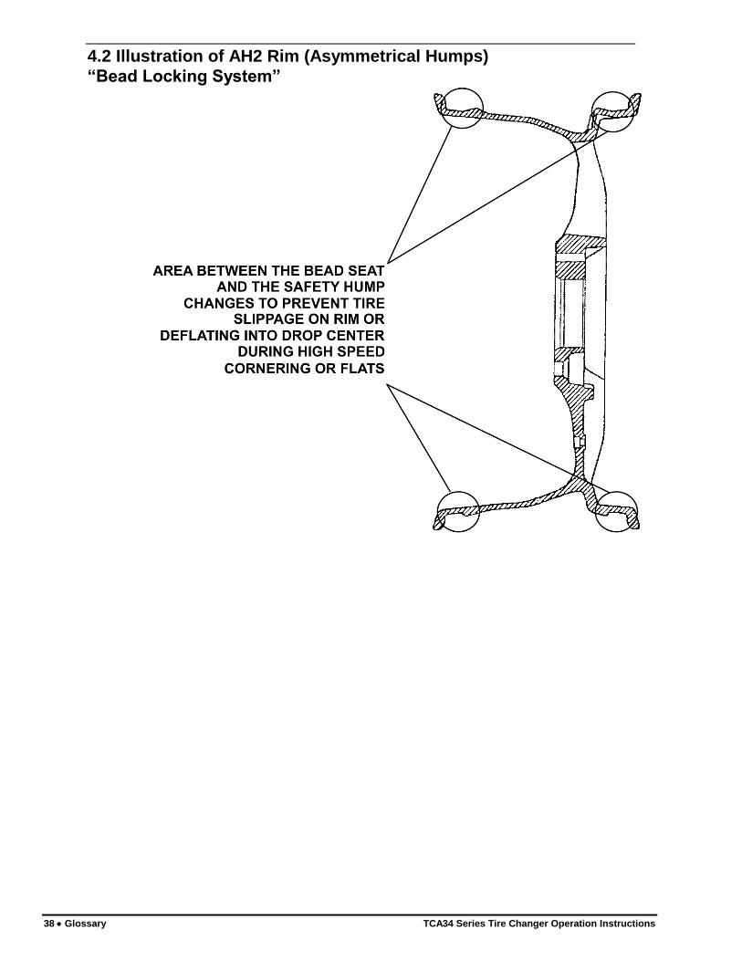
4.2 Illustration of AH2 Rim (Asymmetrical Humps)
“Bead Locking System”
TCA34 Series Tire Changer Operation Instructions Glossary 39
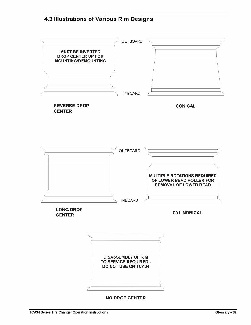
4.3 Illustrations of Various Rim Designs