Embed Size (px)
Citation preview
Manual Tire Changer
Instructions
1
INDEX
Preface………………………………………………………… 2
Warning……………………………………………………… 2
General Description…………………………………………… 3
Demounting Head usage……………………………………… 4
Accessory……………………………………………………… 4
Installation……………………………………………………… 4
Operation……………………………………………………… 6
Maintenance…………………………………………………… 10
Transportation………………………………………………… 10
2
Preface
The TC-500-M Manual Tire Changer offered by Redline Engineering is a
manual tire changer that comes many unique features. Those features include:
1、Ability to handle large diameter rims (max rim diameter 22in.) and ability
to handle run-flat tires.
2、A swing style vertical arm with locking system for safety. This style arm
allows for time saving convenience, good repeatability and ensures quality
protection while mounting and dismounting a tire.
3 、 This model represents quality in design, materials, reliability and
performance. It is easy and simple to use making it the perfect addition to any
shop.
※ Warning ※
1、Read the instructions before using; use within the limits described by the
instructions and pay attention to operational requirements.
2、This machine is limited to the instructions provided in this manual and the
manufacturer within the operation.
3、This machine is designed for the use of changing tires within specification.
Never use for any other purposes! Manufacturer will not assume any responsibility
for improper usage and/or any modifications or alterations done to machine.
4、The TC-500-M is designed for use by a single operator. The operator should
always wear protective eye wear.
3
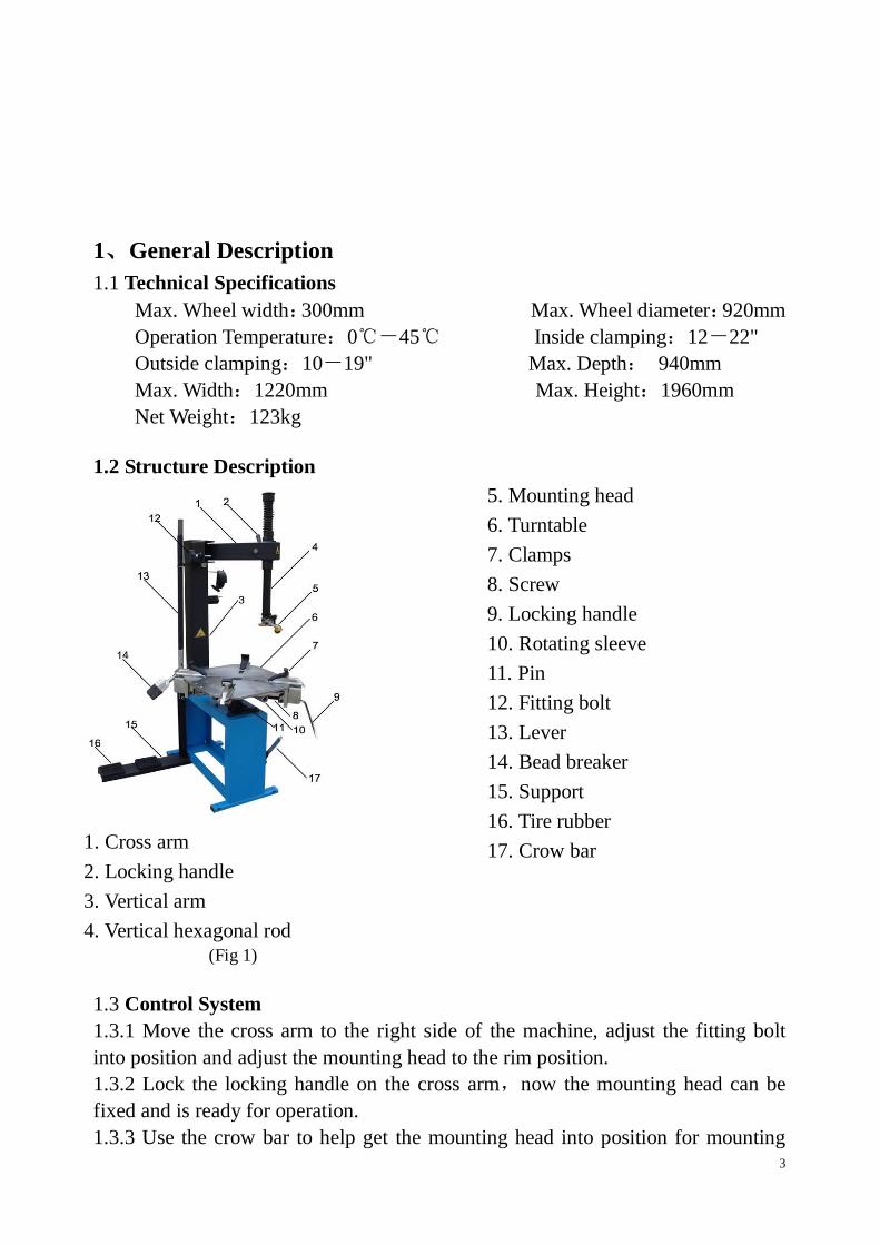
1、General Description
1.1 Technical Specifications
Max. Wheel width:300mm Max. Wheel diameter:920mm
Operation Temperature:0℃-45℃ Inside clamping:12-22"
Outside clamping:10-19" Max. Depth: 940mm
Max. Width:1220mm Max. Height:1960mm
Net Weight:123kg
1.2 Structure Description
1. Cross arm
2. Locking handle
3. Vertical arm
4. Vertical hexagonal rod
5. Mounting head
6. Turntable
7. Clamps
8. Screw
9. Locking handle
10. Rotating sleeve
11. Pin
12. Fitting bolt
13. Lever
14. Bead breaker
15. Support
16. Tire rubber
17. Crow bar
(Fig 1)
1.3 Control System
1.3.1 Move the cross arm to the right side of the machine, adjust the fitting bolt
into position and adjust the mounting head to the rim position.
1.3.2 Lock the locking handle on the cross arm,now the mounting head can be
fixed and is ready for operation.
1.3.3 Use the crow bar to help get the mounting head into position for mounting

4
and dismounting tires
1.4 Auto-centering turntable
1.4.1 The turntable is a synchronistic work station that is made to hold and turn the
wheel.
1.4.2 Put the pin into the hole of the main shaft to keep the turntable in a fixed
position.
1.4.3 Turn the locking handle, all four clamps on the turntable will clamp onto the
rim from the inside or the outside depending on how the wheel is mounted.
1.4.4 Remove the pin from the main shaft so that the turntable can now move
freely.
1.4.5 Put the lever into the rotating sleeve, and rotate the turntable in a clockwise
direction to mount and dismount the tire.
1.5 Bead detacher
1.5.1 Push down on the bead breaker lever to allow bead breaker to detach tire
from wheel.
1.5.2 Make sure to break bead all along both sides of the tire to ensure that bead is
fully detached
2、Mounting Head (Duck Head) Adjustment
2.1 Operation
2.1.1 After breaking the bead and separating the tire from the rim, fix the rim on
the turntable by inside caliper or outside caliper.
2.1.2 Turn the cross arm, drop down the vertical hexagonal shaft, adjust the
mounting head into optimal position and lock the locking handle tightly.
2.1.3 Mount and dismount the tire using the normal operating procedure. 3、Accessories
5
(Fig 2)
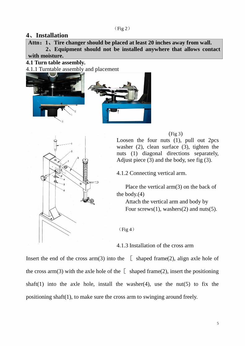
4、Installation Attn:1、Tire changer should be placed at least 20 inches away from wall.
2、Equipment should not be installed anywhere that allows contact
with moisture.
4.1 Turn table assembly.
4.1.1 Turntable assembly and placement
(Fig 3)
Loosen the four nuts (1), pull out 2pcs
washer (2), clean surface (3), tighten the
nuts (1) diagonal directions separately,
Adjust piece (3) and the body, see fig (3).
4.1.2 Connecting vertical arm.
Place the vertical arm(3) on the back of
the body.(4)
Attach the vertical arm and body by
Four screws(1), washers(2) and nuts(5).
(Fig 4)
4.1.3 Installation of the cross arm
Insert the end of the cross arm(3) into the [ shaped frame(2), align axle hole of
the cross arm(3) with the axle hole of the [ shaped frame(2), insert the positioning
shaft(1) into the axle hole, install the washer(4), use the nut(5) to fix the
positioning shaft(1), to make sure the cross arm to swinging around freely.

6
4.1.4. This unit has four holes drilled on the feet to allow anchoring onto a concrete
surface
5、Instructions for tire changing Attn: Please make sure that you have read operators manual and received proper
training before using!
5.1.1 Dismounting tire operation
(Fig 6)
Remove air from tire.
Remove the valve stem core.
Remove the balancing weights on rim
(Fig 6)
5.1.2 Break the tire bead.
(Fig 7)
With the tire flat, brush along the rim
and edge of tire with lubricant.
Place the bead breaker a ½ inch off the
rim onto the tire.
Move the lever down to start breaking
the tire bead. .
Turn the wheel, repeat the above action
until you have freed the tire from all
sides of the rim. Then flip the tire over
and repeat.
7
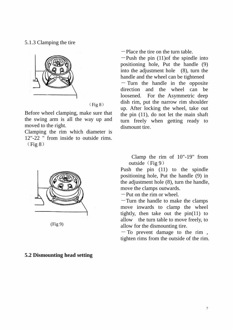
5.1.3 Clamping the tire
(Fig 8)
Before wheel clamping, make sure that
the swing arm is all the way up and
moved to the right.
Clamping the rim which diameter is
12"-22 " from inside to outside rims.
(Fig 8)
-Place the tire on the turn table.
-Push the pin (11)of the spindle into
positioning hole, Put the handle (9)
into the adjustment hole (8), turn the
handle and the wheel can be tightened
- Turn the handle in the opposite
direction and the wheel can be
loosened. For the Asymmetric deep
dish rim, put the narrow rim shoulder
up. After locking the wheel, take out
the pin (11), do not let the main shaft
turn freely when getting ready to
dismount tire.
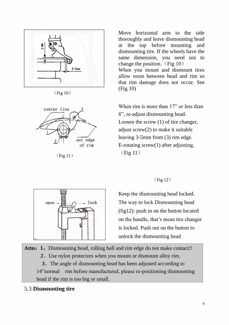
(Fig 9)
5.2 Dismounting head setting
Clamp the rim of 10"-19" from
outside(Fig 9)
Push the pin (11) to the spindle
positioning hole, Put the handle (9) in
the adjustment hole (8), turn the handle,
move the clamps outwards.
-Put on the rim or wheel.
-Turn the handle to make the clamps
move inwards to clamp the wheel
tightly, then take out the pin(11) to
allow the turn table to move freely, to
allow for the dismounting tire.
-To prevent damage to the rim ,
tighten rims from the outside of the rim.
8
(Fig 10)
Move horizontal arm to the side
thoroughly and leave dismounting head
at the top before mounting and
dismounting tire. If the wheels have the
same dimension, you need not to
change the position.(Fig 10)
When you mount and dismount tires
allow room between head and rim so
that rim damage does not occur. See
(Fig 10)
(Fig 11)
When rim is more than 17” or less than
8”, re-adjust dismounting head.
Loosen the screw (1) of tire changer,
adjust screw(2) to make it suitable
leaving 3-5mm from (3) rim edge.
E-rotating screw(1) after adjusting.
(Fig 11)
(Fig 12)
Keep the dismounting head locked.
The way to lock Dismounting head
(fig12): push in on the button located
on the handle, that’s mean tire changer
is locked. Push out on the button to
unlock the dismounting head
5.3 Dismounting tire
Attn:1、Dismounting head, rolling ball and rim edge do not make contact!!
2、Use nylon protectors when you mount or dismount alloy rim.
3、The angle of dismounting head has been adjusted according to
14”normal rim before manufactured, please re-positioning dismounting
head if the rim is too big or small.

9
(Fig 13)
Lubricate rim and edge before dismounting
tire. Once lubricated take the crowbar and pry
the tire edge over the duckhead. Remove the
crowbar, unlock the turn table and start
rotating the turn table clockwise. The top of
the tire should start to slide over the rim. Once
the top of the tire is dismounted. Use the same
steps to remove the bottom side of the tire.
.
(Fig 14)
Repeat above steps and dismount the other rim edge.(fig14)
After dismounting, move the horizontal arm to the side.
5.4 Tire installment
Attn:Check the dimensions of tire and rim before installment.
Clamp rim tightly, make sure there
is 180 degrees between tire
inflating entrance and dismounting
head.
Lubricate rim and edge.
(Fig 15)
10
Set operation model according to 5.2.
Adjust the duckhead to the top of the
rim.
Put the bead pressing block on the rim
edge in front of the dismounting head.
Begin to rotate the turntable in a
clockwise manner. This should allow
the tire edge to slide over the rim.
After installing the tire, take out the
rotating crowbar, unclamp wheel from
turntable.
6、Maintenance
Attn:Cleaning and maintenance should be done by professionals according to
instructions.
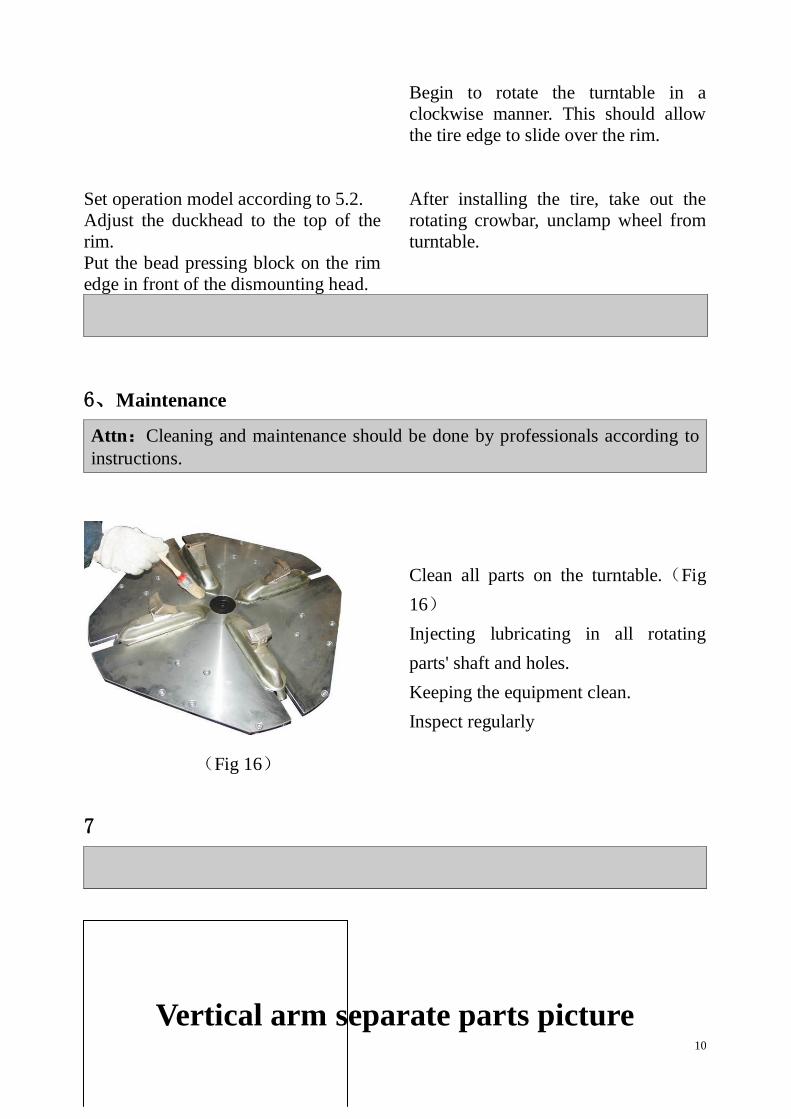
Clean all parts on the turntable.(Fig
16)
Injecting lubricating in all rotating
parts' shaft and holes.
Keeping the equipment clean.
Inspect regularly
(Fig 16)
7
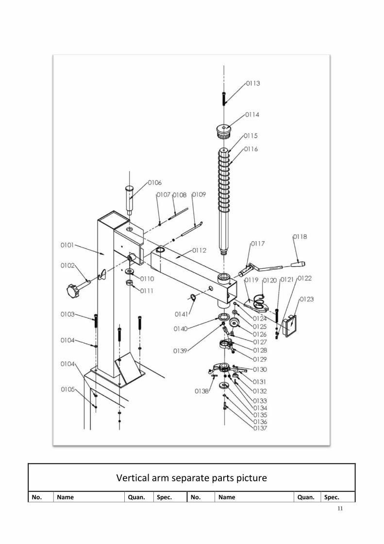
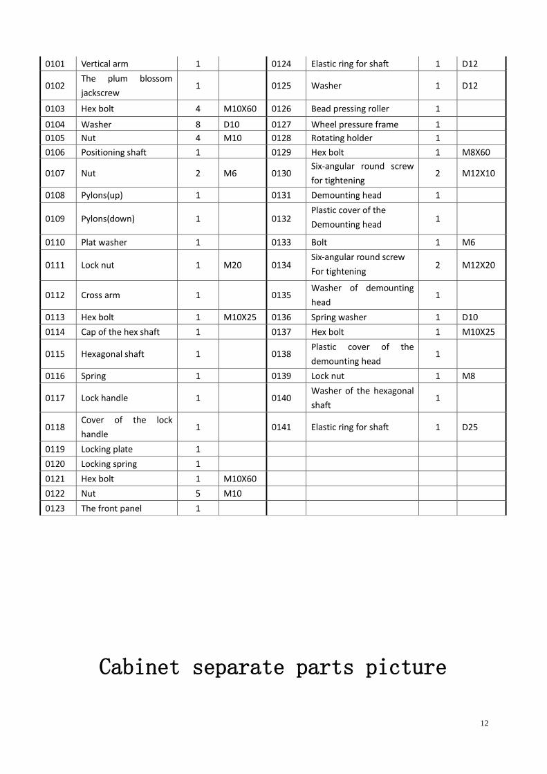
Vertical arm separate parts picture
11
Vertical arm separate parts picture
No. Name Quan. Spec. No. Name Quan. Spec.
12
0101 Vertical arm 1 0124 Elastic ring for shaft 1 D12
0102 The plum blossom
jackscrew 1 0125 Washer 1 D12
0103 Hex bolt 4 M10X60 0126 Bead pressing roller 1
0104 Washer 8 D10 0127 Wheel pressure frame 1
0105 Nut 4 M10 0128 Rotating holder 1
0106 Positioning shaft
Shaft
Shaft
1 0129 Hex bolt 1 M8X60
0107 Nut 2 M6 0130 Six-angular round screw
for tightening 2 M12X10
0108 Pylons(up) 1 0131 Demounting head 1
0109 Pylons(down) 1 0132 Plastic cover of the
Demounting head
Plastic cover of the
demounting head
demounting head
1
0110 Plat washer 1 0133 Bolt 1 M6
0111 Lock nut 1 M20 0134 Six-angular round screw
For tightening
For tightening
2 M12X20
0112 Cross arm 1 0135 Washer of demounting
head 1
0113 Hex bolt 1 M10X25 0136 Spring washer 1 D10
0114 Cap of the hex shaft 1 0137 Hex bolt 1 M10X25
0115 Hexagonal shaft 1 0138 Plastic cover of the
demounting head 1
0116 Spring 1 0139 Lock nut 1 M8
0117 Lock handle 1 0140 Washer of the hexagonal
shaft 1
0118 Cover of the lock
handle 1 0141 Elastic ring for shaft 1 D25
0119 Locking plate 1
0120 Locking spring 1
0121 Hex bolt 1 M10X60
0122 Nut 5 M10
0123 The front panel 1
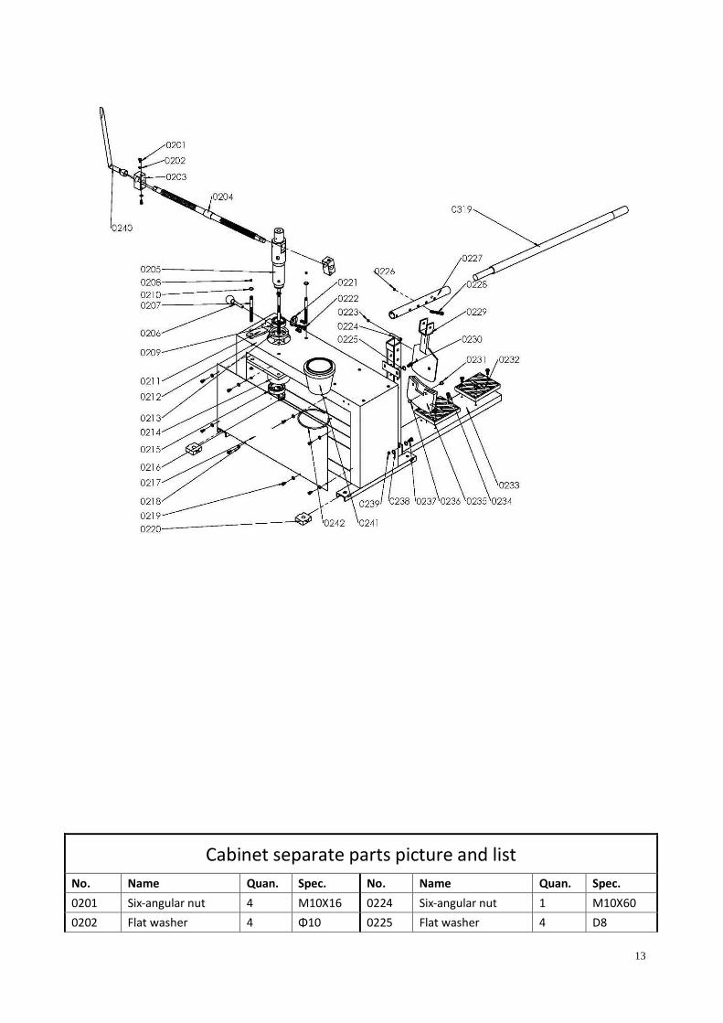
Cabinet separate parts picture
13
Cabinet separate parts picture and list
No. Name Quan. Spec. No. Name Quan. Spec.
0201 Six-angular nut 4 M10X16 0224 Six-angular nut 1 M10X60
0202 Flat washer 4 Φ10 0225 Flat washer 4 D8
14
0203 Nut 2 0226 Nut 1 M10
0204 Vertical shaft screw 1 0227 Bead breaker rob 1
0205 Vertical shaft 1 0228 Six-angular nut 1 M10X60
0206 Stop lever 1 0229 Bead breaker
0207 Nipple 4 M10X170 0230 Six-angular nut 2 M8X25
0208 Nut 8 M10 0231 Protector button 2
0209 6010 shaft 1 0232 cushion block 2
0210 Flat washer 8 D10 0233 Arm of bead breaker 1
0211 Locking supporting
structure 1 0234 Six-angular nut 6 M6X16
0212 Cabinet 1 0235 Protector of bead
breaker 1
0213 Upper cover 1 0236 Protector button 2
0214 Vertical shaft seat 1 0237 Six-angular screw 2 M8X25
0215 6008 shaft 1 0238 Flat washer 4 D8
0216 Lower cover 1 0239 Nut 4 M8
0217 Side box board 2 0240 Spanner 1
0218 Flat washer 16 D5 0241 Lubricant box 1
0219 Six-angular nut 16 M5X10 0242 Support of lubricant 1
0220 Pitch block 4
0221 Vertical shaft end
cover 2
0222 Six-angular nut 8 M5X10
0223 Nut 1 M10
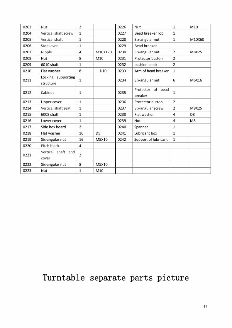
Turntable separate parts picture
15
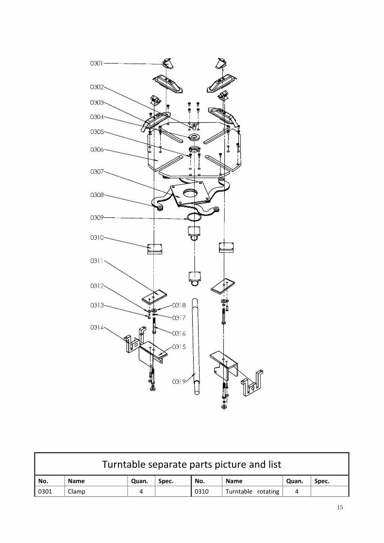
Turntable separate parts picture and list
No. Name Quan. Spec. No. Name Quan. Spec.
0301 Clamp 4 0310 Turntable rotating 4

16
seat
0302 Six-angular nut 1 M16X30 0311 Connected board
of slide 2
0303 Clamp base 4 0312 Spring ring 4 D8
0304 Blockage for
turntable 1 0313 Round bolt 4 M8X25
0305 Round bolt 20 M8X16 0314 lead screw support 2 M8
0306 Turntable 1 0315 Connected board
of slide 2
0307 S-plate 1 0316 Hexagon bolt 4 M12X90
0308 S-plate axis 4 0317 Spring ring 4 D12
0309 Spring spacer ring
for shaft 1 D75 0318 Flat washer ring 4
0319 Wrench level 1