Embed Size (px)
Citation preview

TCP/IP Internetworking
Chapter 8
Panko’sBusiness Data Networks and Telecommunications, 6th edition
Copyright 2007 Prentice-Hall
May only be used by adopters of the book
8-2
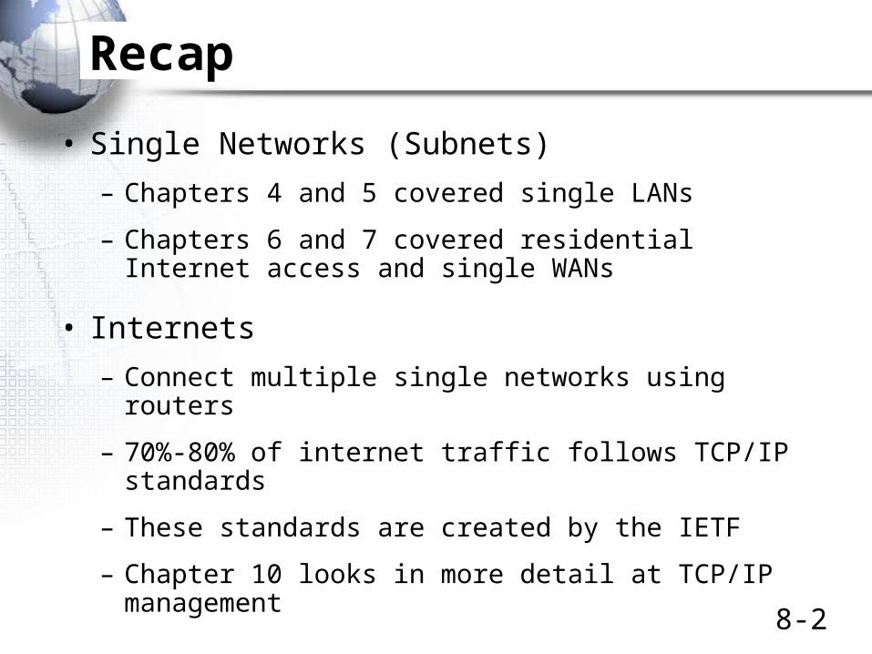
Recap
• Single Networks (Subnets)
– Chapters 4 and 5 covered single LANs
– Chapters 6 and 7 covered residential Internet access and single WANs
• Internets
– Connect multiple single networks using routers
– 70%-80% of internet traffic follows TCP/IP standards
– These standards are created by the IETF
– Chapter 10 looks in more detail at TCP/IP management

8-3
Figure 2-8: Hybrid TCP/IP-OSI Architecture
General Purpose Layer Specific Purpose
Application-application communication
Application (5) Application-application interworking
Transmission across an internet
Transport (4) Host-host communication
Internet (3) Packet delivery across an internet
Transmission across a single network (LAN or WAN)
Data Link (2) Frame delivery across a network
Physical (1) Device-device connection
Recap
TCP/IP standards dominate at theinternet and transport layers—transmission across an internet
8-4
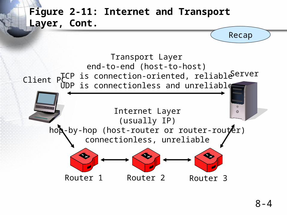
Figure 2-11: Internet and Transport Layer, Cont.
Transport Layerend-to-end (host-to-host)
TCP is connection-oriented, reliableUDP is connectionless and unreliable
Internet Layer(usually IP)
hop-by-hop (host-router or router-router)connectionless, unreliable
Router 1 Router 2 Router 3
Client PCServer
Recap
8-5
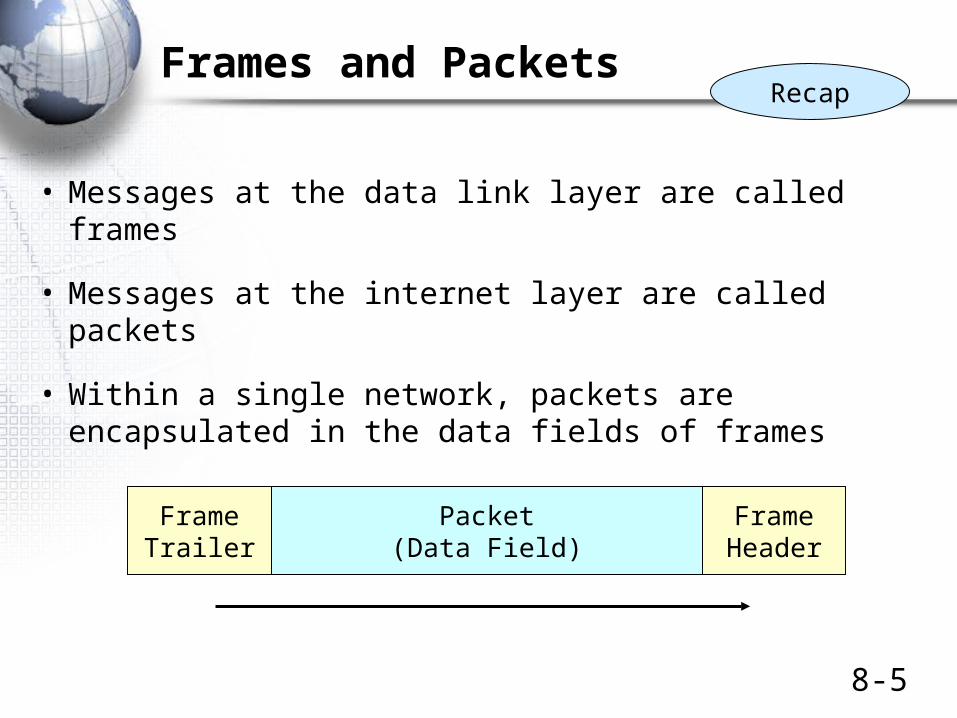
Frames and Packets
• Messages at the data link layer are called frames
• Messages at the internet layer are called packets
• Within a single network, packets are encapsulated in the data fields of frames
FrameHeader
Packet(Data Field)
FrameTrailer
Recap

8-6
Frames and Packets
• In an internet with hosts separated by N networks, there will be:
– 2 hosts
– One packet (going all the way between hosts)
• One route (between the two hosts)
– N frames (one in each network)
• N-1 routers (change frames between each pair of networks)
Recap
8-7
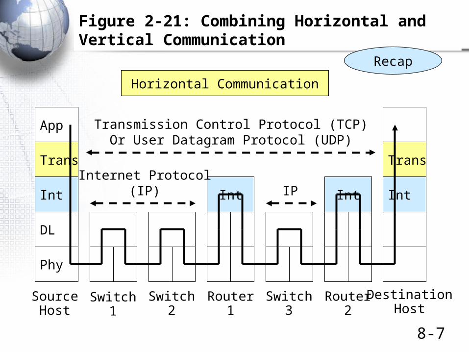
Figure 2-21: Combining Horizontal and Vertical Communication
Int
App
DL
Trans
Phy
Int
Trans
IntInt
SourceHost
DestinationHost
Switch1
Switch2
Router1
Switch3
Router2
Transmission Control Protocol (TCP)Or User Datagram Protocol (UDP)
Internet Protocol(IP)
Recap
Horizontal Communication
IP

8-8
Figure 8-1: Major TCP/IP Standards
5 ApplicationUser Applications
HTTP SMTPMany
OthersDNS
RoutingProtocols
ManyOthers
Supervisory Applications
TCP UDP4 Transport
IP3 InternetMPLS
ARP
None: Use OSI Standards2 Data Link
None: Use OSI Standards1 PhysicalInternetworking is done at the internet and transport layers.
There are only a few standards at these layers.We will look at the shaded protocols in this chapter.
ICMP

8-9
Figure 8-1: Major TCP/IP Standards, Continued
5 ApplicationUser Applications
HTTP SMTPMany
OthersDNS
RoutingProtocols
ManyOthers
Supervisory Applications
TCP UDP4 Transport
IP3 Internet ICMP ARP
None: Use OSI Standards2 Data Link
None: Use OSI Standards1 Physical At the application layer, there areuser applications and supervisory applications.
We will look at two TCP/IP application layer supervisory applications in this chapter.
8-10
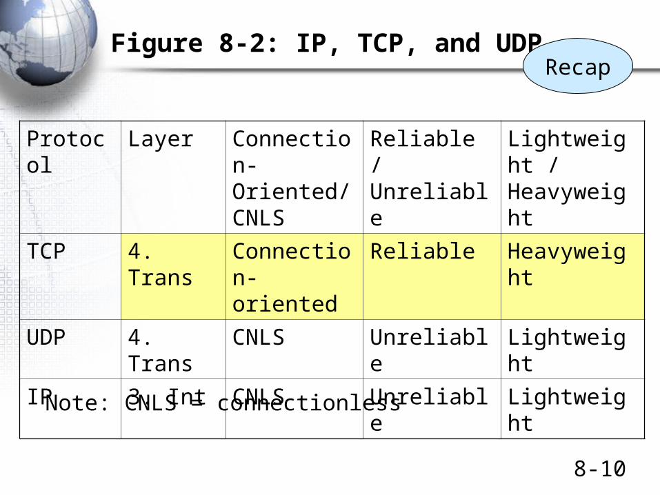
Figure 8-2: IP, TCP, and UDP
Protocol Layer Connection-Oriented/ CNLS
Reliable / Unreliable
Lightweight / Heavyweight
TCP 4. Trans Connection- oriented
Reliable Heavyweight
UDP 4. Trans CNLS Unreliable Lightweight
IP 3. Int CNLS Unreliable Lightweight
Note: CNLS = connectionless
Recap
IP Addresses
8-12
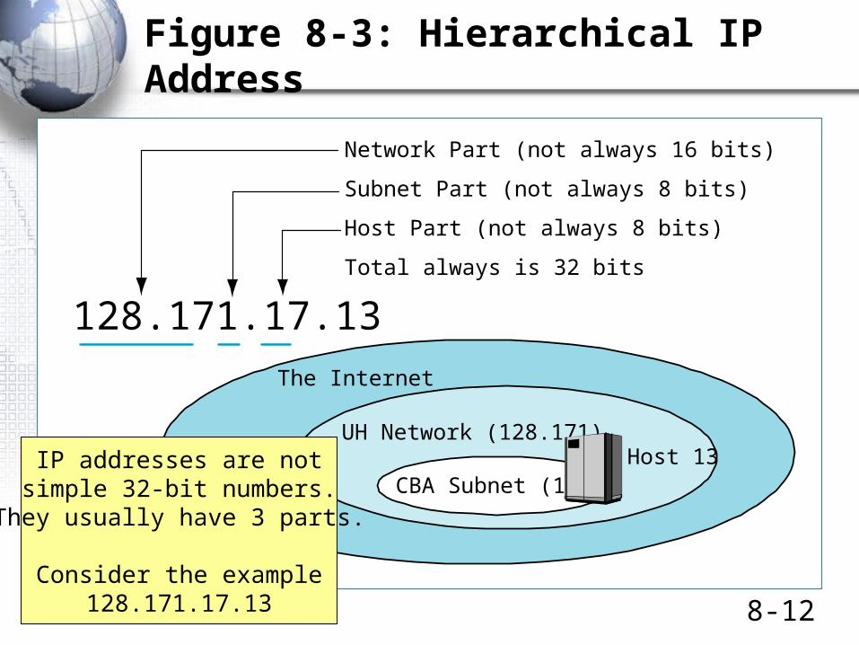
Figure 8-3: Hierarchical IP Address
128.171.17.13
Network Part (not always 16 bits)
Subnet Part (not always 8 bits)
Host Part (not always 8 bits)
Total always is 32 bits
UH Network (128.171)
CBA Subnet (17)Host 13
The Internet
Figure 8-3: Hierarchical IP Address
IP addresses are notsimple 32-bit numbers.
They usually have 3 parts.
Consider the example128.171.17.13
8-13
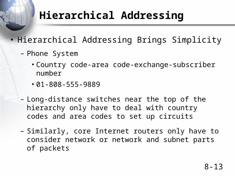
Hierarchical Addressing
• Hierarchical Addressing Brings Simplicity
– Phone System
• Country code-area code-exchange-subscriber number
• 01-808-555-9889
– Long-distance switches near the top of the hierarchy only have to deal with country codes and area codes to set up circuits
– Similarly, core Internet routers only have to consider network or network and subnet parts of packets
8-14
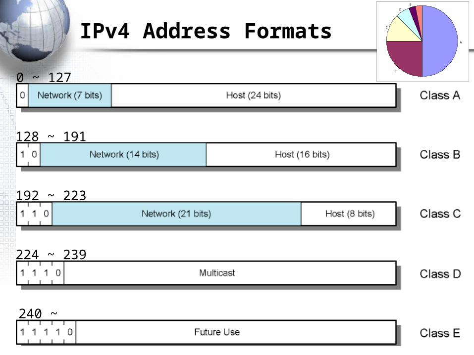
IPv4 Address Formats
0 ~ 127
128 ~ 191
192 ~ 223
224 ~ 239
240 ~
A
B
C
D
E
8-15
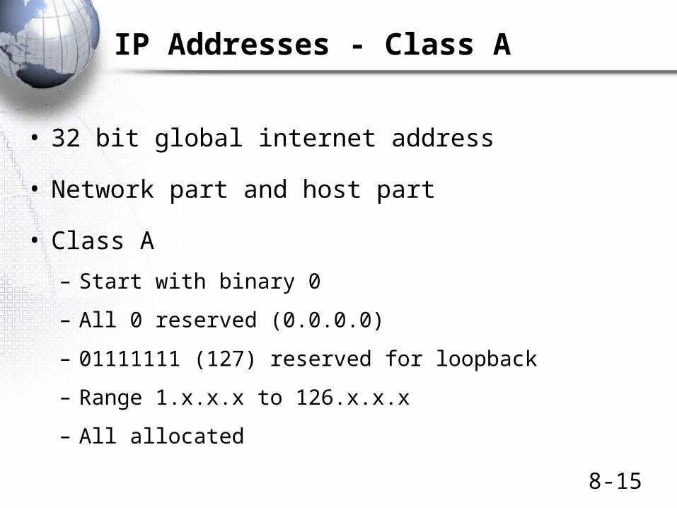
IP Addresses - Class A
• 32 bit global internet address
• Network part and host part
• Class A
– Start with binary 0
– All 0 reserved (0.0.0.0)
– 01111111 (127) reserved for loopback
– Range 1.x.x.x to 126.x.x.x
– All allocated

8-16
IP Addresses - Class B
• Start 10
• Range 128.x.x.x to 191.x.x.x
• Second Octet also included in network address
• 214 = 16,384 class B addresses
• All allocated

8-17
IP Addresses - Class C
• Start 110
• Range 192.x.x.x to 223.x.x.x
• Second and third octet also part of network address
• 221 = 2,097,152 addresses
• Nearly all allocated
– See IPv6

8-18
Special IP Addresses
• All-0 host suffix Network Address– 163.22.20.16/24 163.22.20.0/24
• All-1 host suffix All hosts on the destination net(directed broadcast)
163.22.20.16/24 163.22.20.255• All-0s This computer
– 0.0.0.0
• All-1s All hosts on this net (limited broadcast)– 255.255.255.255Subnet number cannot be all 1
• All-0s network This network.– 163.22.20.7/24 0.0.0.7 (Host 7 on this network)
• 127.*.*.* Loopback through IP layer– 127.0.0.1

8-19
Private IP Addresses
• Any organization can use these inside their network
• Can’t go on the internet. [RFC 1918]
– 10.0.0.0 - 10.255.255.255 (10/8 prefix)
– 172.16.0.0 - 172.31.255.255 (172.16/12 prefix)
– 192.168.0.0 - 192.168.255.255 (192.168/16 prefix)
• Network Address Translation (NAT)
– Basic NAT (one-to-one NAT)
– NAT(NAPT, Network Address Port Translation)
116256
Router Operation
8-21
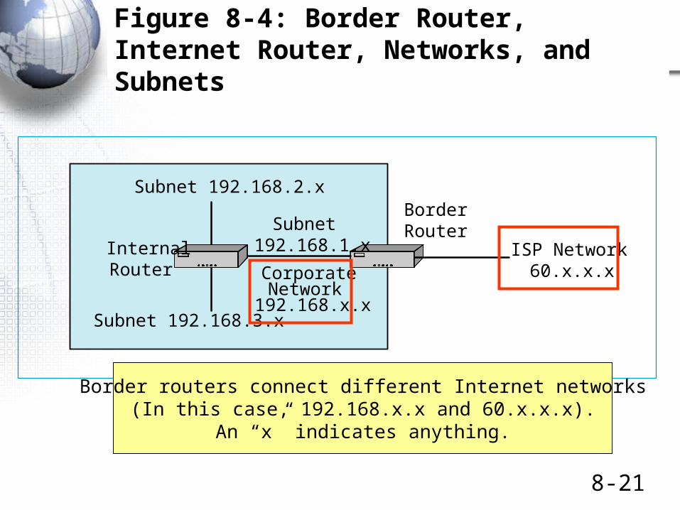
Figure 8-4: Border Router, Internet Router, Networks, and Subnets
Figure 8-4: Border Router, Internal Router, Networks, and Subnets
ISP Network60.x.x.x
Subnet 192.168.2.x
Subnet 192.168.3.x
Subnet192.168.1.xInternal
Router
BorderRouter
CorporateNetwork
192.168.x.x
Border routers connect different Internet networks(In this case, 192.168.x.x and 60.x.x.x).
An “x” indicates anything.
8-22
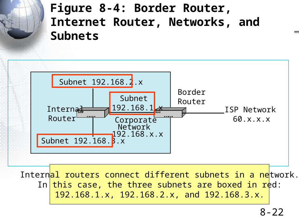
Figure 8-4: Border Router, Internet Router, Networks, and Subnets
Figure 8-4: Border Router, Internal Router, Networks, and Subnets
ISP Network60.x.x.x
Subnet 192.168.2.x
Subnet 192.168.3.x
Subnet192.168.1.xInternal
Router
BorderRouter
CorporateNetwork
192.168.x.x
Internal routers connect different subnets in a network.In this case, the three subnets are boxed in red:
192.168.1.x, 192.168.2.x, and 192.168.3.x.

8-23
Figure 8-5: Multiprotocol Routing
MultiprotocolRouter
X TCP/IP
TCP/IP
IPX/SPX
SNA
WWWServer
EdgeRouter
Z
Site ASite B
Mainframe
InternalRouter
Y
EthernetLAN 1
EthernetLAN 2
EthernetLan 3
The Internet
OldNetWareServer
UNIXServer
Figure 8-5: Multiprotocol Routing
Real routers must handle multipleinternet and transport layer architectures—
TCP/IP, IPX/SPX, SNA, etc.We will only look at TCP/IP routing
8-24
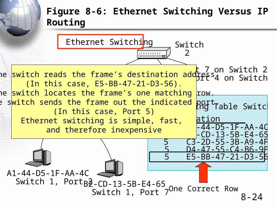
Figure 8-6: Ethernet Switching Versus IP Routing
A1-44-D5-1F-AA-4CSwitch 1, Port 2 B2-CD-13-5B-E4-65
Switch 1, Port 7
Port 7 on Switch 2to Port 4 on Switch 3
Port 5 on Switch 1to Port 3 on Switch 2
Switch2
Switch1
Switching Table Switch 1
Port Station2 A1-44-D5-1F-AA-4C7 B2-CD-13-5B-E4-655 C3-2D-55-3B-A9-4F5 D4-47-55-C4-B6-9F5 E5-BB-47-21-D3-56
Ethernet Switching
The switch reads the frame’s destination address(In this case, E5-BB-47-21-D3-56).
The switch locates the frame’s one matching row.The switch sends the frame out the indicated port.
(In this case, Port 5)Ethernet switching is simple, fast,
and therefore inexpensive
One Correct Row
8-25
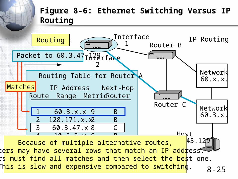
Figure 8-6: Ethernet Switching Versus IP Routing
Network60.x.x.x
Packet to 60.3.47.129
Router B
Router C
Interface1
Interface2
Network60.x.x.x
IP Routing
Network60.3.x.x
Route
123456
IP AddressRange
60.3.x.x128.171.x.x60.3.47.x10.5.3.x
128.171.17.x10.4.3.x
Metric
928622
Router A
Routing Table for Router A
Host60.3.45.129
Next-HopRouter
BBCB
LocalC
Routing
Because of multiple alternative routes,Routers may have several rows that match an IP address.
Routers must find all matches and then select the best one.This is slow and expensive compared to switching.
Matches
8-26
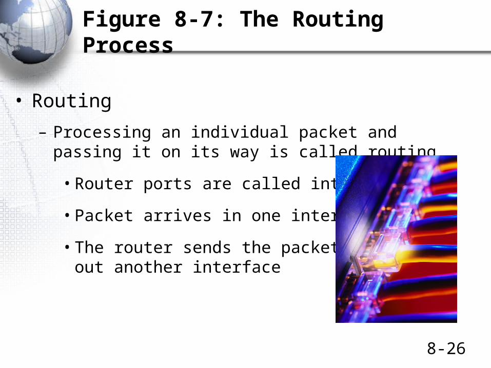
Figure 8-7: The Routing Process
• Routing
– Processing an individual packet and passing it on its way is called routing
• Router ports are called interfaces
• Packet arrives in one interface
• The router sends the packetout another interface
8-27
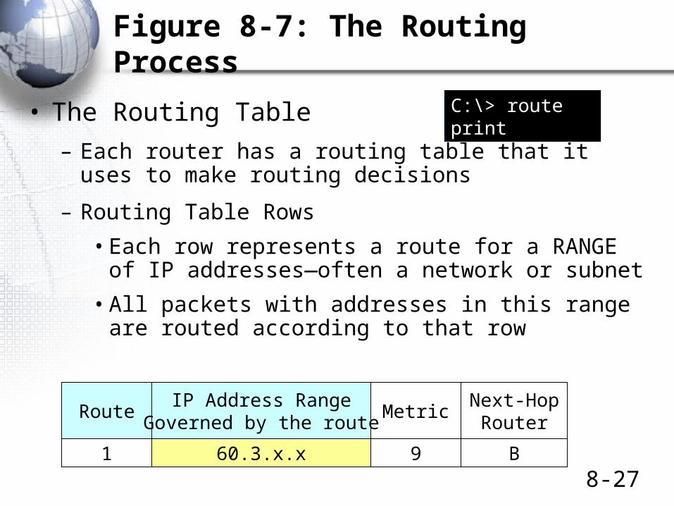
Figure 8-7: The Routing Process
• The Routing Table
– Each router has a routing table that it uses to make routing decisions
– Routing Table Rows
• Each row represents a route for a RANGE of IP addresses—often a network or subnet
• All packets with addresses in this range are routed according to that row
RouteIP Address Range
Governed by the routeMetric
Next-HopRouter
1 60.3.x.x 9 B
C:\> route print
8-28
Figure 8-7: The Routing Process
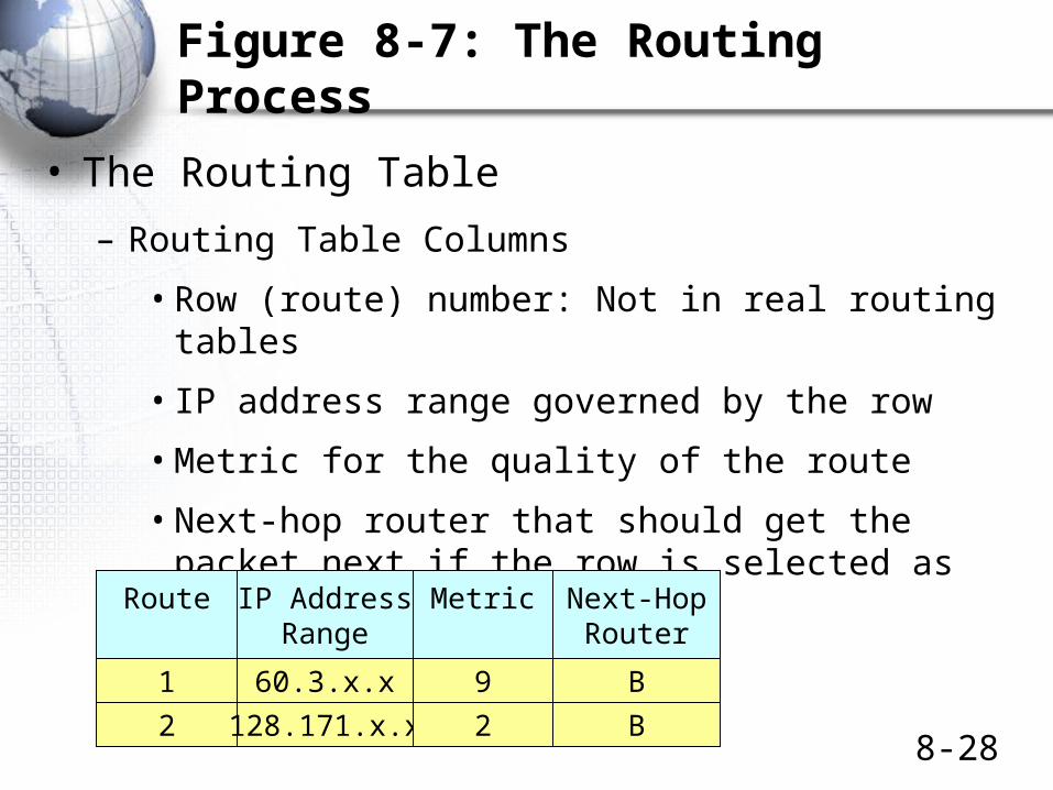
• The Routing Table
– Routing Table Columns
• Row (route) number: Not in real routing tables
• IP address range governed by the row
• Metric for the quality of the route
• Next-hop router that should get the packet next if the row is selected as the best match
Route IP AddressRange
Metric Next-HopRouter
1 60.3.x.x 9 B
2 128.171.x.x 2 B
8-29
Figure 8-7: The Routing Process
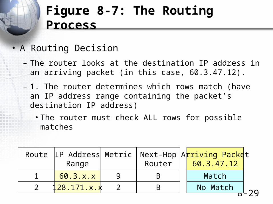
• A Routing Decision
– The router looks at the destination IP address in an arriving packet (in this case, 60.3.47.12).
– 1. The router determines which rows match (have an IP address range containing the packet’s destination IP address)
• The router must check ALL rows for possible matches
Route IP AddressRange
Metric Next-HopRouter
1 60.3.x.x 9 B
2 128.171.x.x 2 B
Arriving Packet60.3.47.12
Match
No Match
8-30
Figure 8-7: The Routing Process
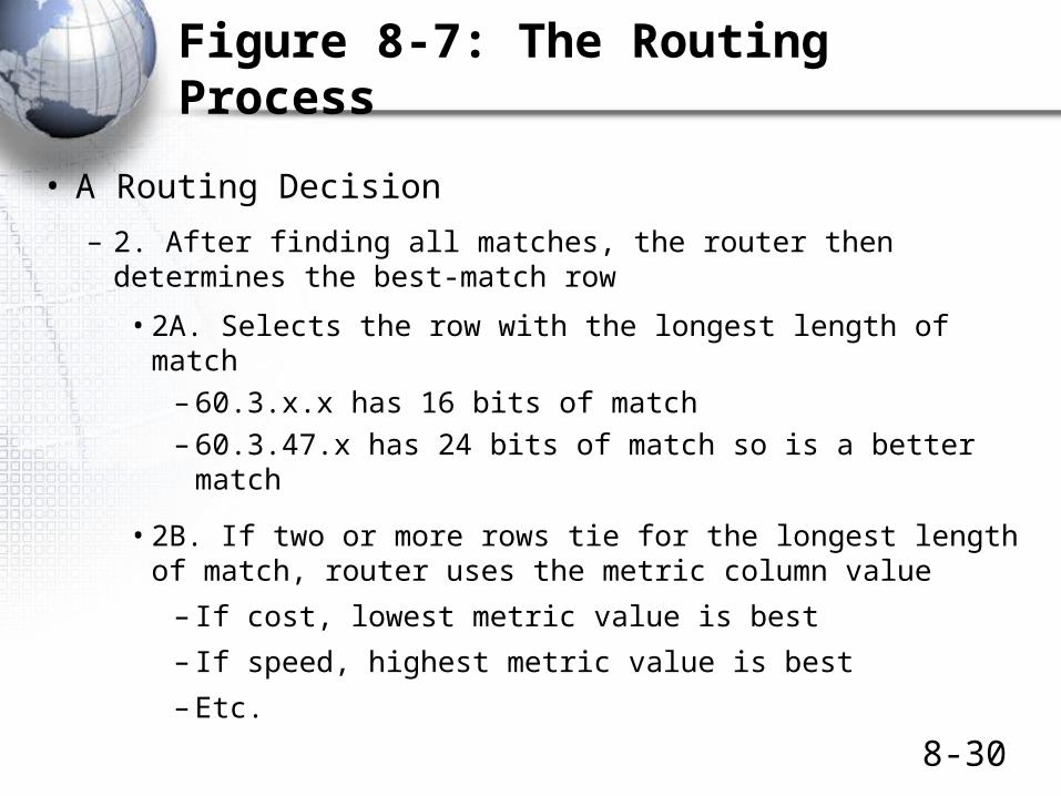
• A Routing Decision
– 2. After finding all matches, the router then determines the best-match row
• 2A. Selects the row with the longest length of match– 60.3.x.x has 16 bits of match– 60.3.47.x has 24 bits of match so is a better match
• 2B. If two or more rows tie for the longest length of match, router uses the metric column value
– If cost, lowest metric value is best
– If speed, highest metric value is best
– Etc.
8-31
Figure 8-7: The Routing Process
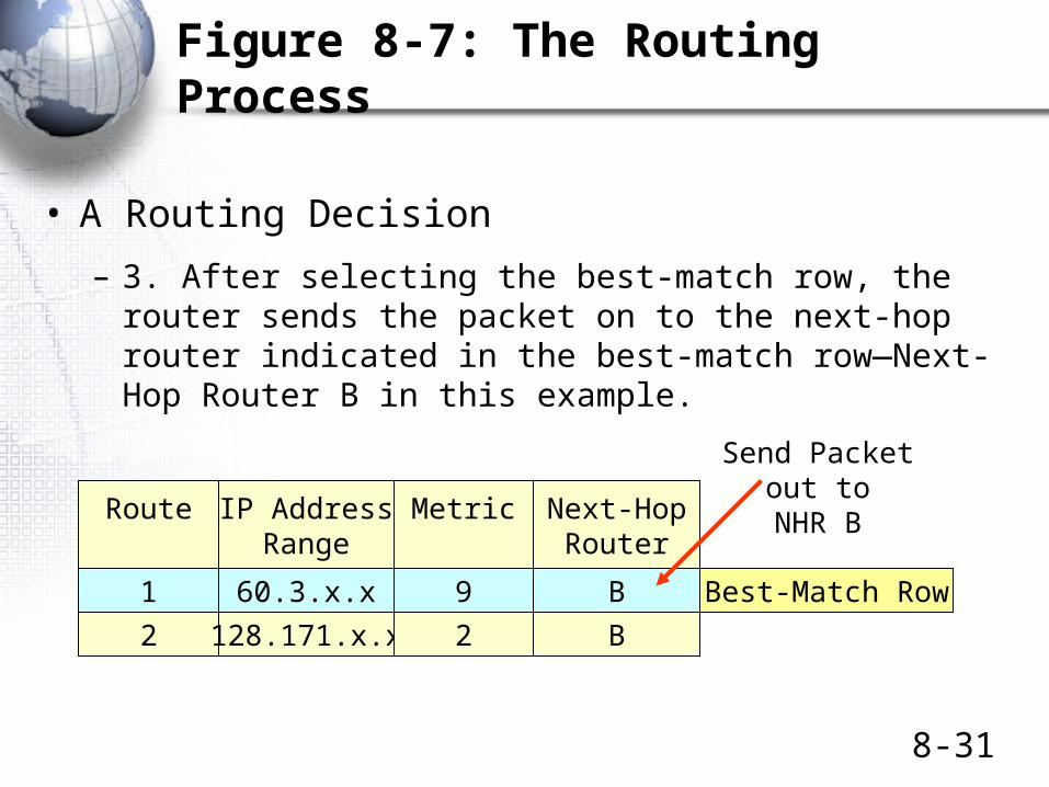
• A Routing Decision
– 3. After selecting the best-match row, the router sends the packet on to the next-hop router indicated in the best-match row—Next-Hop Router B in this example.
Route IP AddressRange
Metric Next-HopRouter
1 60.3.x.x 9 B
2 128.171.x.x 2 B
Best-Match Row
Send Packetout to
NHR B
A More Detailed Look at Routing Decisions
Box

8-33
Figure 8-8: Detailed Row-Matching Algorithm
• Routing Table
IP Address Range
Row Destination Mask … … …
1 10.7.3.0 255.255.255.0 … … …
2 … … … … …
3 … … … … …
Box
Actually, the table does not really have an “IP Address Range” column.It has two columns to indicate the IP address range:
Destination (an IP address) and a mask

8-34
Figure 8-8: Detailed Row-Matching Algorithm
• 1. Basic Rule of Masking
– Information Bit 1 0 1 0
– Mask Bit 1 1 0 0
– Result 1 0 0 0
• Where mask bits are one, the result gives the original IP address bits
• Where mask bits are zero, the result contains zeros
Box

8-35
Figure 8-8: Detailed Row-Matching Algorithm
• 2. Example
– Address (partial) 10101010 11001110
– Mask 11111000 00000000
– Result 10101000 00000000
Box
8-36
Figure 8-8: Detailed Row-Matching Algorithm
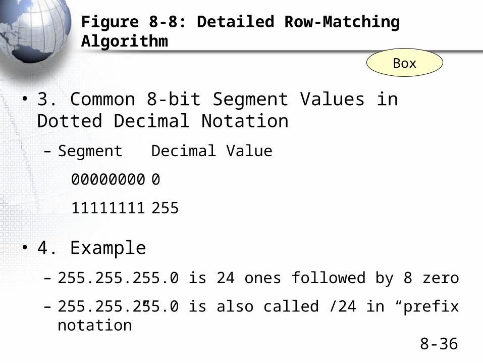
• 3. Common 8-bit Segment Values in Dotted Decimal Notation
– Segment Decimal Value
00000000 0
11111111 255
• 4. Example
– 255.255.255.0 is 24 ones followed by 8 zero
– 255.255.255.0 is also called /24 in “prefix notation”
Box

8-37
Figure 8-8: Detailed Row-Matching Algorithm
• Example 1: A Destination IP Address that is in the Range
• Destination IP Address of Arriving Packet 10.7.3.47
• Apply the Mask 255.255.255.0
• Result of Masking 10.7.3.0
• Destination Value 10.7.3.0
• Does Destination Value Match the Masking Result? Yes
• Conclusion Row 1 is a
match.
Row Destination Mask … … …
1 10.7.3.0 255.255.255.0 … … …
Box

8-38
Figure 8-8: Detailed Row-Matching Algorithm
• Example 2: A Destination IP Address that is NOT in the Range
• Destination IP Address of Arriving Packet 10.7.5.47
• Apply the Mask 255.255.255.0
• Result of Masking 10.7.5.0
• Destination Value 10.7.3.0
• Does Destination Value Match the Masking Result? No
• Conclusion Row 1 is NOT a
match.
Row Destination Mask … … …
1 10.7.3.0 255.255.255.0 … … …
Box
8-39
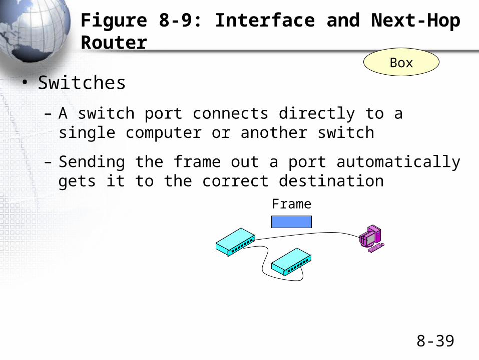
Figure 8-9: Interface and Next-Hop Router
• Switches
– A switch port connects directly to a single computer or another switch
– Sending the frame out a port automatically gets it to the correct destination
Frame
Box

8-40
Figure 8-9: Interface and Next-Hop Router
• Routers
– Router ports (interfaces) connect to subnets, which have multiple hosts and that may have multiple routers
– The packet must be forwarded to a specific host or router on that subnet
Subneton RouterInterface
IPPacket
Next-HopRouter
Host
Host
Box
8-41
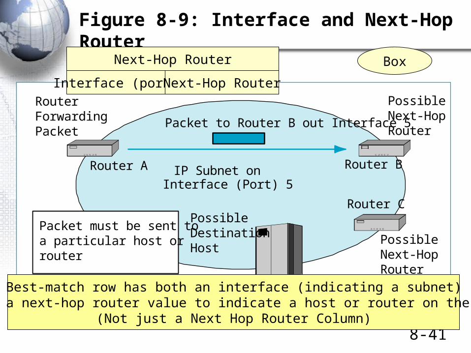
Figure 8-9: Interface and Next-Hop Router
RouterForwardingPacket
Figure 8-9: Interface and Next-Hop Router
IP Subnet onInterface (Port) 5
PossibleNext-HopRouter
PossibleDestinationHost
Packet must be sent toa particular host orrouter
Router A Router B
Packet to Router B out Interface 5
PossibleNext-HopRouter
Router C
Box
Best-match row has both an interface (indicating a subnet)and also a next-hop router value to indicate a host or router on the subnet.
(Not just a Next Hop Router Column)
Interface (port) Next-Hop Router
Next-Hop Router
Dynamic Routing Protocols
Routing Table Information
Dynamic Routing Protocol
8-43
Figure 8-10: Dynamic Routing Protocols (Study Figure)
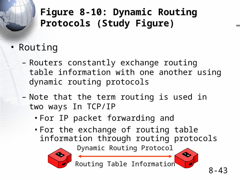
• Routing
– Routers constantly exchange routing table information with one another using dynamic routing protocols
– Note that the term routing is used in two ways In TCP/IP
• For IP packet forwarding and
• For the exchange of routing table information through routing protocols
Routing Table Information
Dynamic Routing Protocol

8-44
Figure 8-10: Dynamic Routing Protocols (Study Figure)
• Autonomous System– An organization’s internal network (internet)
• Interior Dynamic Routing Protocols– Within an Autonomous System, firms use interior
dynamic routing protocols
• Exterior Dynamic Routing Protocols– Between Autonomous Systems, companies use an
exterior dynamic routing protocol

8-45
Figure 8-10: Dynamic Routing Protocols (Study Figure)
• Interior Dynamic Routing Protocols
– As just discussed, within an Autonomous System, firms use interior dynamic routing protocols
– The organization can freely select an interior routing protocol
• RIP
• OSPF
• EIGRP
• Etc.

8-46
Figure 8-10: Dynamic Routing Protocols (Study Figure)
• Routing Information Protocol (RIP)
– Simple interior dynamic routing protocol from the IETF
– Low-cost management
– Poor efficiency: metric is merely the number of router hops to the destination host
• No way to select cheapest route, etc.
– Weak security
– Useful only in small firms

8-47
8-48
Figure 8-10: Dynamic Routing Protocols (Study Figure)
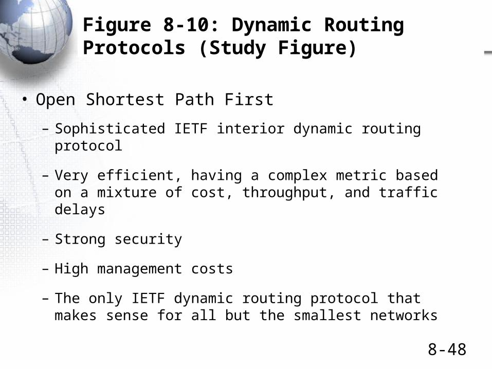
• Open Shortest Path First
– Sophisticated IETF interior dynamic routing protocol
– Very efficient, having a complex metric based on a mixture of cost, throughput, and traffic delays
– Strong security
– High management costs
– The only IETF dynamic routing protocol that makes sense for all but the smallest networks
8-49
Figure 8-10: Dynamic Routing Protocols (Study Figure)
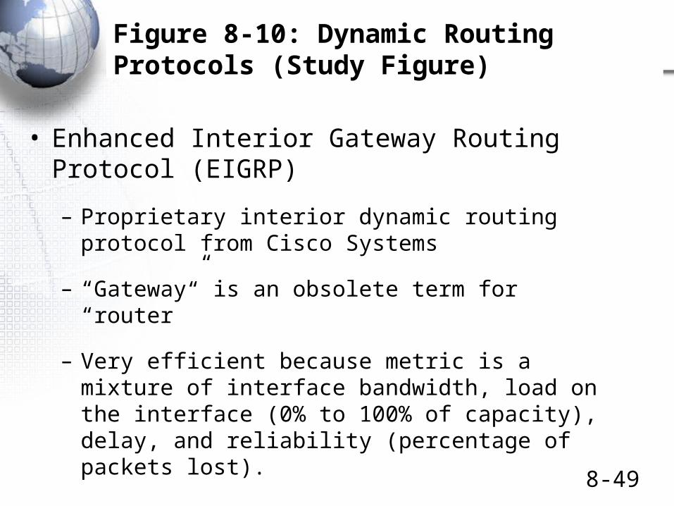
• Enhanced Interior Gateway Routing Protocol (EIGRP)
– Proprietary interior dynamic routing protocol from Cisco Systems
– “Gateway” is an obsolete term for “router”
– Very efficient because metric is a mixture of interface bandwidth, load on the interface (0% to 100% of capacity), delay, and reliability (percentage of packets lost).

8-50
Figure 8-10: Dynamic Routing Protocols (Study Figure)
• Enhanced Interior Gateway Routing Protocol (EIGRP)
– Only interior dynamic routing protocol that supports multiprotocol routing (not just TCP/IP): IPX/SPX, SNA, etc.
– But to use it, a company must buy Cisco routers

8-51
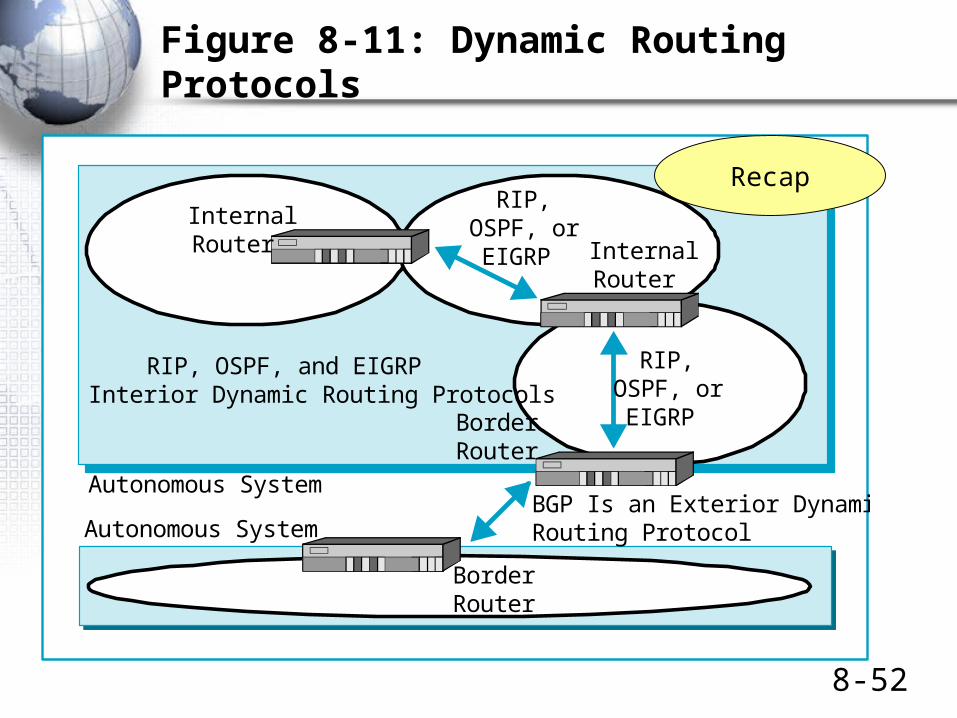
Figure 8-10: Dynamic Routing Protocols (Study Figure)
• Exterior Dynamic Routing Protocols
– Between autonomous systems, companies use an exterior dynamic routing protocol
– An organization is not free to select an exterior routing protocol
• It must select a protocol selected by its ISP
– Border Gateway Protocol (BGP) is the main exterior routing protocol
• Recall that “gateway” is the old term for “router”
8-52
Figure 8-11: Dynamic Routing Protocols
Autonomous System
InternalRouter
BGP Is an Exterior DynamicRouting ProtocolAutonomous System
RIP,OSPF, orEIGRP
RIP,OSPF, orEIGRP
InternalRouter
BorderRouter
BorderRouter
RIP, OSPF, and EIGRPInterior Dynamic Routing Protocols
Figure 8-11: Dynamic Routing Protocols
Recap

The Address Resolution Protocol (ARP)
8-54
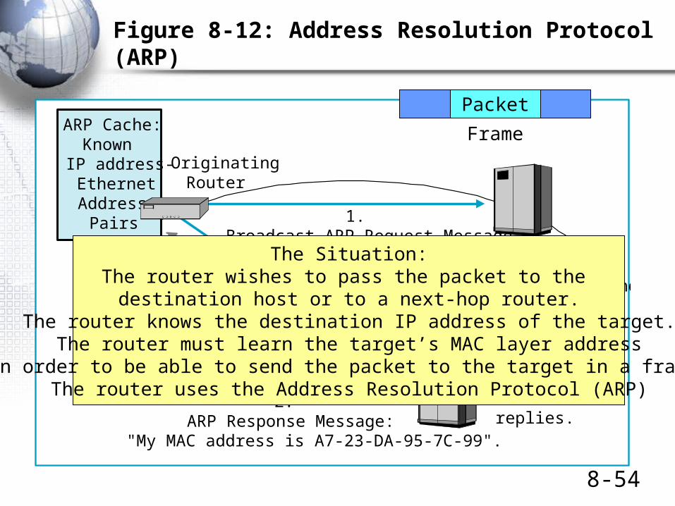
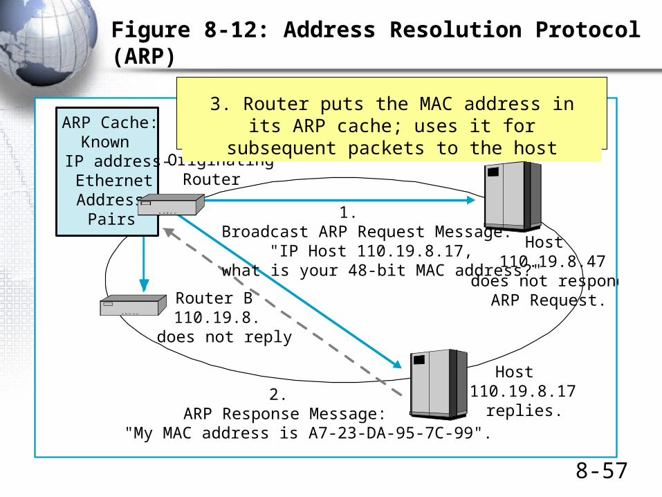
Figure 8-12: Address Resolution Protocol (ARP)
OriginatingRouter
Host110.19.8.47
does not respond toARP Request.
1.Broadcast ARP Request Message:
"IP Host 110.19.8.17,what is your 48-bit MAC address?"
Host110.19.8.17
replies.2.
ARP Response Message:"My MAC address is A7-23-DA-95-7C-99".
Figure 8-12: Address Resolution Protocol (ARP)
Router B110.19.8.
does not reply
ARP Cache:Known
IP address-EthernetAddress
Pairs
The Situation:The router wishes to pass the packet to the
destination host or to a next-hop router.The router knows the destination IP address of the target.
The router must learn the target’s MAC layer addressin order to be able to send the packet to the target in a frame.
The router uses the Address Resolution Protocol (ARP)
Packet
Frame

8-55
OriginatingRouter
Host110.19.8.47
does not respond toARP Request.
1.Broadcast ARP Request Message:
"IP Host 110.19.8.17,what is your 48-bit MAC address?"
Host110.19.8.17
replies.2.
ARP Response Message:"My MAC address is A7-23-DA-95-7C-99".
Figure 8-12: Address Resolution Protocol (ARP)
Router B110.19.8.
does not reply
ARP Cache:Known
IP address-EthernetAddress
Pairs
Figure 8-12: Address Resolution Protocol (ARP)
1: Router broadcasts ARP Request to all hosts and routers on the subnet.

8-56
OriginatingRouter
Host110.19.8.47
does not respond toARP Request.
1.Broadcast ARP Request Message:
"IP Host 110.19.8.17,what is your 48-bit MAC address?"
Host110.19.8.17
replies.2.
ARP Response Message:"My MAC address is A7-23-DA-95-7C-99".
Figure 8-12: Address Resolution Protocol (ARP)
Router B110.19.8.
does not reply
ARP Cache:Known
IP address-EthernetAddress
Pairs
Figure 8-12: Address Resolution Protocol (ARP)
This is theDestination host
2: ARP Reply sent by the host with the target IP address.
Other hosts ignore it.
8-57
OriginatingRouter
Host110.19.8.47
does not respond toARP Request.
1.Broadcast ARP Request Message:
"IP Host 110.19.8.17,what is your 48-bit MAC address?"
Host110.19.8.17
replies.2.
ARP Response Message:"My MAC address is A7-23-DA-95-7C-99".
Figure 8-12: Address Resolution Protocol (ARP)
Router B110.19.8.
does not reply
ARP Cache:Known
IP address-EthernetAddress
Pairs
Figure 8-12: Address Resolution Protocol (ARP)
3. Router puts the MAC address in its ARP cache; uses it for subsequent packets to the host

8-58

C:\>arp -a
Interface: 10.10.34.169 --- 0x2
Internet Address Physical Address Type
10.10.34.231 00-12-cf-28-cd-20 dynamic
10.10.34.234 00-12-cf-29-c6-80 dynamic
10.10.34.235 00-12-cf-28-1e-20 dynamic
10.10.34.238 00-12-cf-28-4d-e0 dynamic
10.10.34.239 00-12-cf-25-23-40 dynamic
10.10.34.240 00-12-cf-28-bf-e0 dynamic
10.10.34.254 00-08-e3-dd-b3-1f dynamic
arp -aarp -d 10.10.34.235arp -d *arp –s 157.55.85.212 00-aa-00-62-c6-09arp -?
C:\>arp -s 10.10.34.235 00-12-cf-28-1e-20
C:\>arp –a
Interface: 10.10.34.169 --- 0x2 Internet Address Physical Address Type 10.10.34.235 00-12-cf-28-1e-20 static 10.10.34.254 00-08-e3-dd-b3-1f dynamic
Multiprotocol Label Switching (MPLS)
8-61
Figure 8-13: Multiprotocol Label Switching (MPLS)
• Routers are Connected in a Mesh
– Multiple alternative routes make the choice of an outgoing interface very expensive
• PSDNs (Chapter 7) also are Arranged in a Mesh
– However, a best path (virtual circuit) is set up before transmission begins
– Once a VC is in place, subsequent frames are handled quickly and inexpensively
• MPLS Does Something Like this for Routers

8-62
Figure 8-13: Multiprotocol Label Switching (MPLS)
• MPLS Adds a Label Before Each Packet
– Label sits between the frame header and the IP header
– Contains an MPLS label number
– Like a virtual circuit number in a PSDN frame
– Label-switching router merely looks up the MPLS label number in its MPLS table and sends the packet back out
Data LinkHeader
MPLSLabel
IPPacket

8-63
Figure 8-13: Multiprotocol Label Switching (MPLS)
• Advantages of MPLS
– Router does a simple table lookup. This is fast and therefore inexpensive per packet handled
• As fast as Ethernet switching!
– Can use multiple label numbers to give to traffic between sites for multiple levels of priority or quality of service guarantees
– MPLS supports traffic engineering: balancing traffic on an internet

8-64
Figure 8-13: Multiprotocol Label Switching (MPLS)Figure 8-13: Multiprotocol Label Switching (MPLS)
Label-SwitchedPath
Label-SwitchingRouter 1
Label-SwitchingRouter 2
Label-SwitchingRouter 3
Label-SwitchingRouter 4
Label-SwitchingRouter 5Packet Label
Legend
Label-Switching TableLabelACF
Interface113
MPLS reduces forwarding costs and permits traffic engineering,including quality of service and traffic load balancing
First routeradds the label
Last routerdrops the label
The Domain Name System (DNS)

8-66
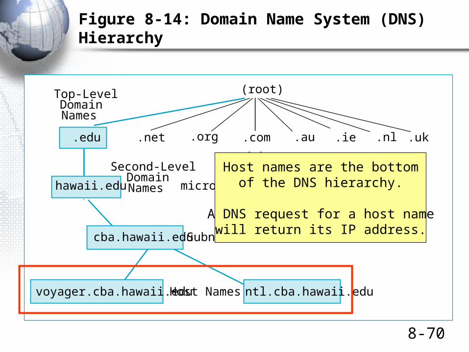
Figure 8-14: Domain Name System (DNS) Hierarchy
(root)
cnn.commicrosoft.comhawaii.edu
.com .uk.ie.edu .net
Top-LevelDomainNames
Second-LevelDomainNames
Subnet Namecba.hawaii.edu
voyager.cba.hawaii.edu ntl.cba.hawaii.eduHost Names
Figure 8-14: Domain Name System (DNS) Hierarchy
.nl.org .auA domain is a group of resources
under the control of an organization.
The domain name system is ageneral system for managing names.
It is a hierarchical naming system.
Queries to a DNS server can getInformation about a domain.
8-67
Figure 8-14: Domain Name System (DNS) Hierarchy
(root)
cnn.commicrosoft.comhawaii.edu
.com .uk.ie.edu .net
Top-LevelDomainNames
Second-LevelDomainNames
Subnet Namecba.hawaii.edu
voyager.cba.hawaii.edu ntl.cba.hawaii.eduHost Names
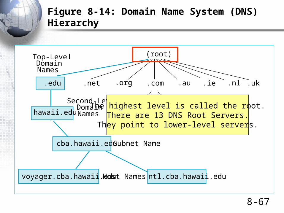
Figure 8-14: Domain Name System (DNS) Hierarchy
.nl.org .au
The highest level is called the root.There are 13 DNS Root Servers.They point to lower-level servers.

8-68
Figure 8-14: Domain Name System (DNS) Hierarchy
(root)
cnn.commicrosoft.comhawaii.edu
.com .uk.ie.edu .net
Top-LevelDomainNames
Second-LevelDomainNames
Subnet Namecba.hawaii.edu
voyager.cba.hawaii.edu ntl.cba.hawaii.eduHost Names
Figure 8-14: Domain Name System (DNS) Hierarchy
.nl.org .au
Top-level domains aregeneric TLDs (.com, .net., .org, etc.) or
country TLDs (.ca, .uk, .ie, etc.)
8-69
Figure 8-14: Domain Name System (DNS) Hierarchy
(root)
cnn.commicrosoft.comhawaii.edu
.com .uk.ie.edu .net
Top-LevelDomainNames
Second-LevelDomainNames
Subnet Namecba.hawaii.edu
voyager.cba.hawaii.edu ntl.cba.hawaii.eduHost Names
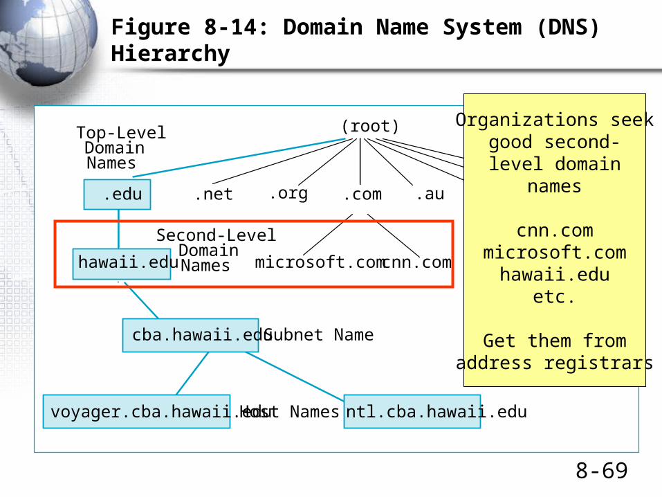
Figure 8-14: Domain Name System (DNS) Hierarchy
.nl.org .au
Organizations seekgood second-level domain
names
cnn.commicrosoft.com
hawaii.eduetc.
Get them fromaddress registrars
8-70
Figure 8-14: Domain Name System (DNS) Hierarchy
(root)
cnn.commicrosoft.comhawaii.edu
.com .uk.ie.edu .net
Top-LevelDomainNames
Second-LevelDomainNames
Subnet Namecba.hawaii.edu
voyager.cba.hawaii.edu ntl.cba.hawaii.eduHost Names
Figure 8-14: Domain Name System (DNS) Hierarchy
.nl.org .au
Host names are the bottomof the DNS hierarchy.
A DNS request for a host namewill return its IP address.
The Internet Control Message Protocol (ICMP)

8-72
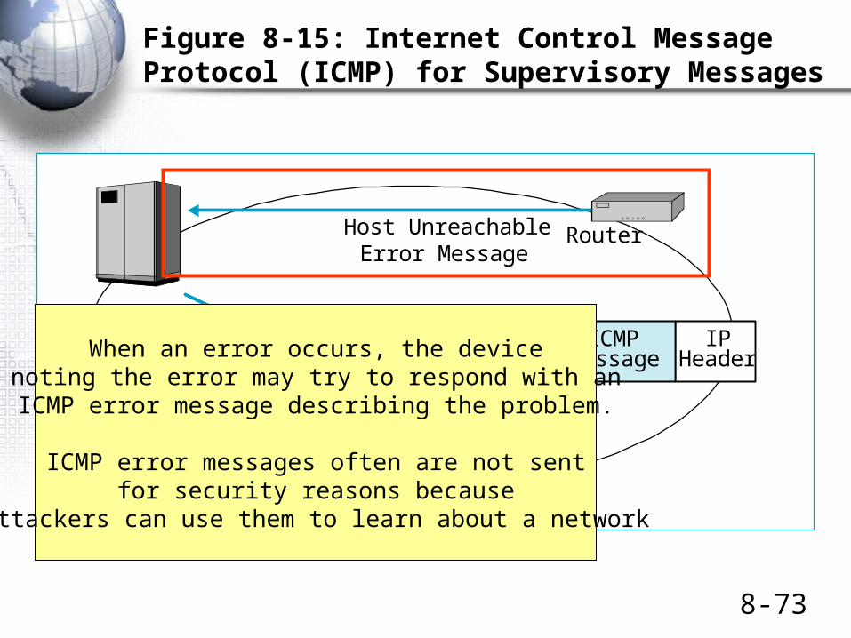
Figure 8-15: Internet Control Message Protocol (ICMP) for Supervisory Messages
RouterHost UnreachableError Message
Echo Request(Ping)
EchoResponse
Figure 8-15: Internet Control Message Protocol (ICMP) for Supervisory Messages
IPHeader
ICMPMessage
ICMP is the supervisory protocolat the internet layer.
ICMP messages are encapsulated in thedata fields of IP packets
8-73
Figure 8-15: Internet Control Message Protocol (ICMP) for Supervisory Messages
RouterHost UnreachableError Message
Echo Request(Ping)
EchoResponse
Figure 8-15: Internet Control Message Protocol (ICMP) for Supervisory Messages
IPHeader
ICMPMessageWhen an error occurs, the device
noting the error may try to respond with anICMP error message describing the problem.
ICMP error messages often are not sentfor security reasons because
attackers can use them to learn about a network

8-74
Figure 8-15: Internet Control Message Protocol (ICMP) for Supervisory Messages
RouterHost UnreachableError Message
Echo Request(Ping)
EchoResponse
Figure 8-15: Internet Control Message Protocol (ICMP) for Supervisory Messages
IPHeader
ICMPMessage
To see if another host is active, a hostcan send the target host an ICMP echo request
message (called a ping).
If the host is active, it will send back anecho response message confirming that it is active.

8-75
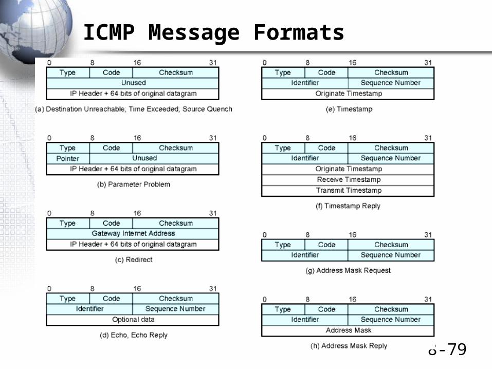
ICMP Type
Echo Request / Echo Reply
Destination Unreachable
Source Quench
Redirect
Time Exceeded
Parameter Problem
Timestamp Request / Timestamp Reply
Address Mask Request / Address Mask Reply
8 / 0
3
4
5
11
12
13 / 14
17 / 18

8-76
Figure 8-16: Dynamic Host Configuration Protocol (DHCP)
• DHCP Gives Each Client PC at Boot-Up:
– A temporary IP Address
– A subnet mask
– The IP addresses of local DNS servers
• Better Than Manual Configuration
– If subnet mask or DNS IP addresses change, only the DHCP server has to be updated manually
– Client PCs are automatically updated when they next boot up

8-77
動態主機組態協定 (DHCP)
• Dynamic Host Configuration Protocol
• 自動設定電腦的– IP 位址 (163.22.20.223)
– 子網路遮罩 (255.255.255.0)
– 預設通訊閘 (163.22.20.254)
– 領域名稱伺服器 (163.22.2.1)
– …
• winipcfg (Win 98/Me)
• ipconfig /all (Win 2000/XP)

8-78
12
3
控制台 網路和網際網路連線
8-79
ICMP Message Formats

8-80
8-81
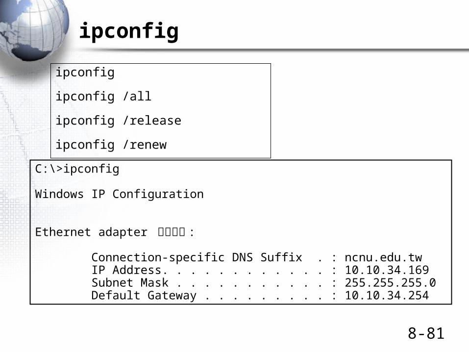
ipconfig
ipconfig
ipconfig /all
ipconfig /release
ipconfig /renew
C:\>ipconfig
Windows IP Configuration
Ethernet adapter 區域連線 :
Connection-specific DNS Suffix . : ncnu.edu.tw IP Address. . . . . . . . . . . . : 10.10.34.169 Subnet Mask . . . . . . . . . . . : 255.255.255.0 Default Gateway . . . . . . . . . : 10.10.34.254

The Internet Protocol (IP)
Versions 4 and 6
8-83
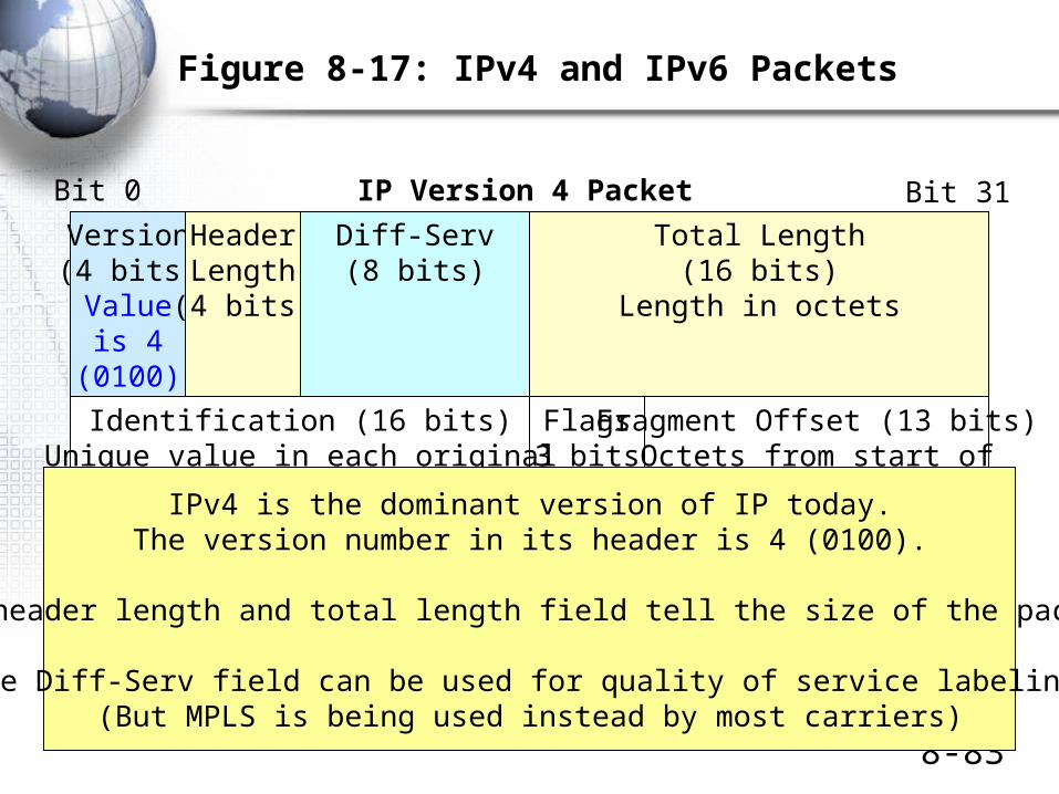
Figure 8-17: IPv4 and IPv6 Packets
IP Version 4 Packet
Version(4 bits)Valueis 4
(0100)
HeaderLength(4 bits)
Flags(3 bits)
Time to Live(8 bits)
Header Checksum(16 bits)
Diff-Serv(8 bits)
Total Length(16 bits)
Length in octets
Bit 0 Bit 31
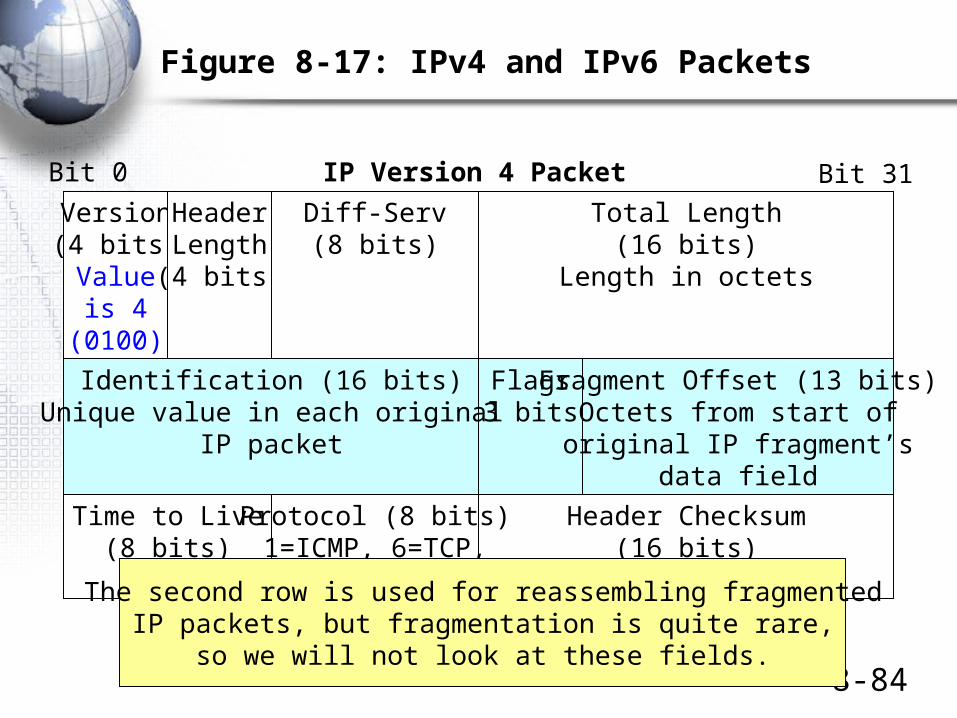
Identification (16 bits)Unique value in each original
IP packet
Fragment Offset (13 bits)Octets from start of
original IP fragment’sdata field
Protocol (8 bits)1=ICMP, 6=TCP,
17=UDP
IPv4 is the dominant version of IP today.The version number in its header is 4 (0100).
The header length and total length field tell the size of the packet.
The Diff-Serv field can be used for quality of service labeling.(But MPLS is being used instead by most carriers)
8-84
Figure 8-17: IPv4 and IPv6 Packets
IP Version 4 Packet
Version(4 bits)Valueis 4
(0100)
HeaderLength(4 bits)
Flags(3 bits)
Time to Live(8 bits)
Header Checksum(16 bits)
Diff-Serv(8 bits)
Total Length(16 bits)
Length in octets
Bit 0 Bit 31
Identification (16 bits)Unique value in each original
IP packet
Fragment Offset (13 bits)Octets from start of
original IP fragment’sdata field
Protocol (8 bits)1=ICMP, 6=TCP,
17=UDPThe second row is used for reassembling fragmentedIP packets, but fragmentation is quite rare,
so we will not look at these fields.

8-85
Figure 8-17: IPv4 and IPv6 Packets
IP Version 4 Packet
Version(4 bits)Valueis 4
(0100)
HeaderLength(4 bits)
Flags(3 bits)
Time to Live(8 bits)
Header Checksum(16 bits)
Diff-Serv(8 bits)
Total Length(16 bits)
Length in octets
Bit 0 Bit 31
Identification (16 bits)Unique value in each original
IP packet
Fragment Offset (13 bits)Octets from start of
original IP fragment’sdata field
Protocol (8 bits)1=ICMP, 6=TCP,
17=UDP
The sender sets the time-to-live value (usually 64 to 128).Each router along the way decreases the value by one.
A router decreasing the value to zero discards the packet.It may send an ICMP error message.
The protocol field describes the message in the data field(ICMP, TCP, UDP, etc.)
The header checksum is used to find errors in the header.If a packet has an error, the router drops it.
There is no retransmission at the internet layer,so the internet layer is still unreliable.
http://www.iana.org/assignments/protocol-numbers
8-86
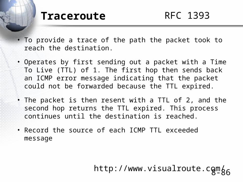
Traceroute
• To provide a trace of the path the packet took to reach the destination.
• Operates by first sending out a packet with a Time To Live (TTL) of 1. The first hop then sends back an ICMP error message indicating that the packet could not be forwarded because the TTL expired.
• The packet is then resent with a TTL of 2, and the second hop returns the TTL expired. This process continues until the destination is reached.
• Record the source of each ICMP TTL exceeded message
RFC 1393
http://www.visualroute.com/

8-87

8-88

8-89

8-90
Figure 8-17: IPv4 and IPv6 Packets
IP Version 4 Packet
Source IP Address (32 bits)
Bit 0 Bit 31
Destination IP Address (32 bits)
PaddingOptions (if any)
Data Field
The source and destination IP addressesAre 32 bits long, as you would suspect.
Options can be added, but these are rare.

8-91
Figure 8-17: IPv4 and IPv6 Packets
IP Version 6 Packet
Source IP Address (128 bits)
Bit 0 Bit 31
Hop Limit(8 bits)
Next Header(8 bits) Nameof next header
Payload Length(16 bits)
Version(4 bits)Valueis 6
(0110)
Diff-Serv(8 bits)
Flow Label (20 bits)Marks a packet as part of a specific flow
Destination IP Address (128 bits)
Next Header or Payload (Data Field)
IP Version 6 is the emergingversion of the Internet protocol.
Has 128 bit addresses foran almost unlimited number of IP addresses.
Growing fastest in Asia, which wasshort-changed in IPv4 address allocations

8-92
IPv6 Header
8-93
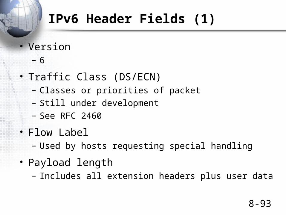
IPv6 Header Fields (1)
• Version– 6
• Traffic Class (DS/ECN)– Classes or priorities of packet– Still under development– See RFC 2460
• Flow Label– Used by hosts requesting special handling
• Payload length– Includes all extension headers plus user data

8-94
IPv6 Header Fields (2)
• Next Header
– Identifies type of header
• Extension or next layer up
• Source Address
• Destination address
8-95
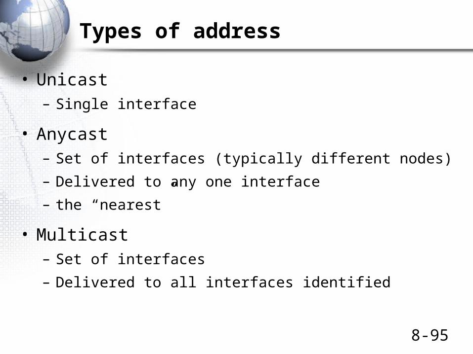
Types of address
• Unicast– Single interface
• Anycast– Set of interfaces (typically different nodes)
– Delivered to any one interface
– the “nearest”
• Multicast– Set of interfaces
– Delivered to all interfaces identified

8-96
Text Representation of IPv6 Addresses
• x:x:x:x:x:x:x:x
• hexadecimal values of the eight 16-bit pieces of the address.– FEDC:BA98:7654:3210:FEDC:BA98:7654:3210
– 1080:0:0:0:8:800:200C:417A
RFC 3513
8-97
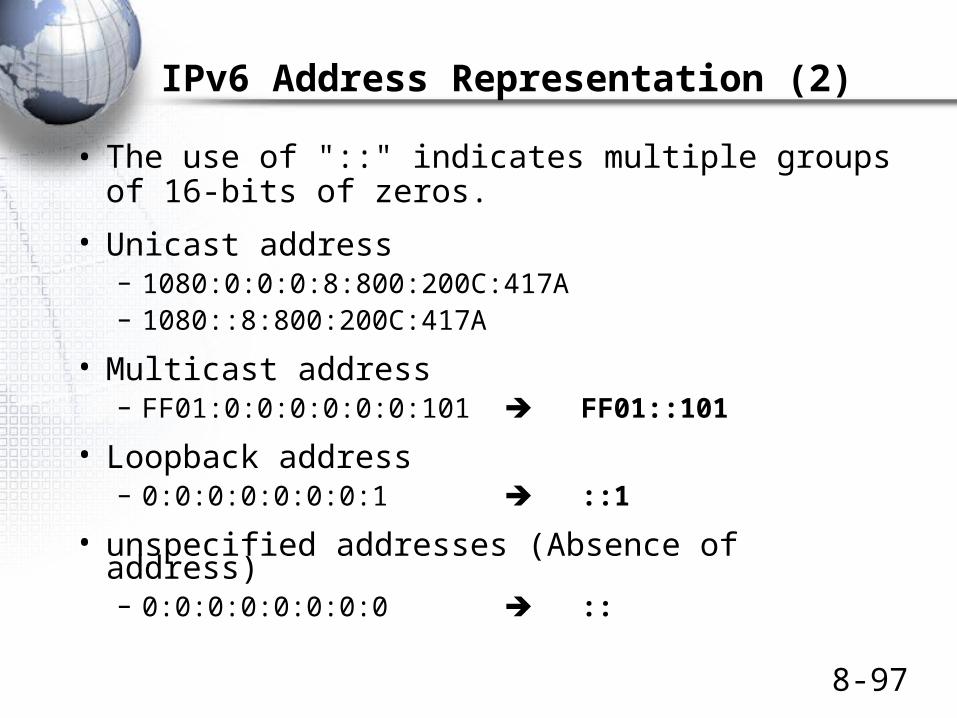
IPv6 Address Representation (2)
• The use of "::" indicates multiple groups of 16-bits of zeros.
• Unicast address – 1080:0:0:0:8:800:200C:417A– 1080::8:800:200C:417A
• Multicast address – FF01:0:0:0:0:0:0:101 FF01::101
• Loopback address– 0:0:0:0:0:0:0:1 ::1
• unspecified addresses (Absence of address)– 0:0:0:0:0:0:0:0 ::
8-98
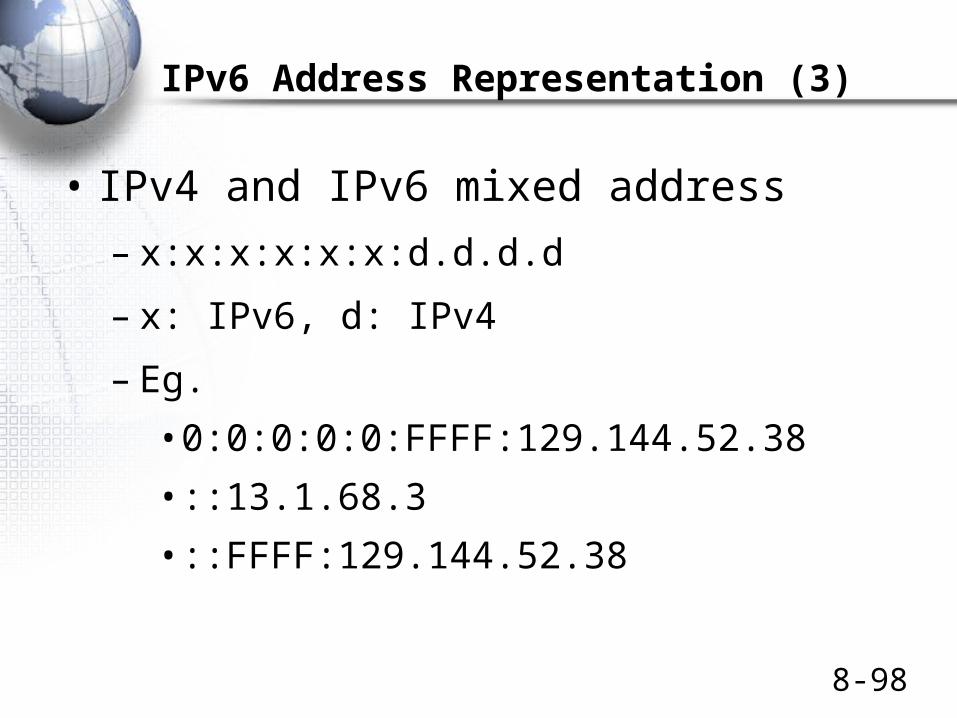
IPv6 Address Representation (3)
• IPv4 and IPv6 mixed address
– x:x:x:x:x:x:d.d.d.d
– x: IPv6, d: IPv4
– Eg.
• 0:0:0:0:0:FFFF:129.144.52.38
• ::13.1.68.3
• ::FFFF:129.144.52.38

The Transmission Control Protocol (TCP)

8-100
Figure 8-18: TCP Segment and UDP Datagram
TCP Segment
Window Size(16 bits)
Bit 0 Bit 31
Destination Port Number (16 bits)Source Port Number (16 bits)
Sequence Number (32 bits)
Acknowledgment Number (32 bits)
Urgent Pointer (16 bits)TCP Checksum (16 bits)
HeaderLength(4 bits)
Reserved(6 bits)
Flag Fields(6 bits)
Flag fields are one-bit fields. They include SYN, ACK, FIN,and RST.
The source and destination port numbersspecify a particular application on the
source and destination multitasking computers(Discussed later)
Sequence numbers are 32 bits long.So are acknowledgment numbers.
8-101
Figure 8-18: TCP Segment and UDP Datagram
TCP Segment
Window Size(16 bits)
Bit 0 Bit 31
Destination Port Number (16 bits)Source Port Number (16 bits)
Sequence Number (32 bits)
Acknowledgment Number (32 bits)
Urgent Pointer (16 bits)TCP Checksum (16 bits)
HeaderLength(4 bits)
Reserved(6 bits)
Flag Fields(6 bits)
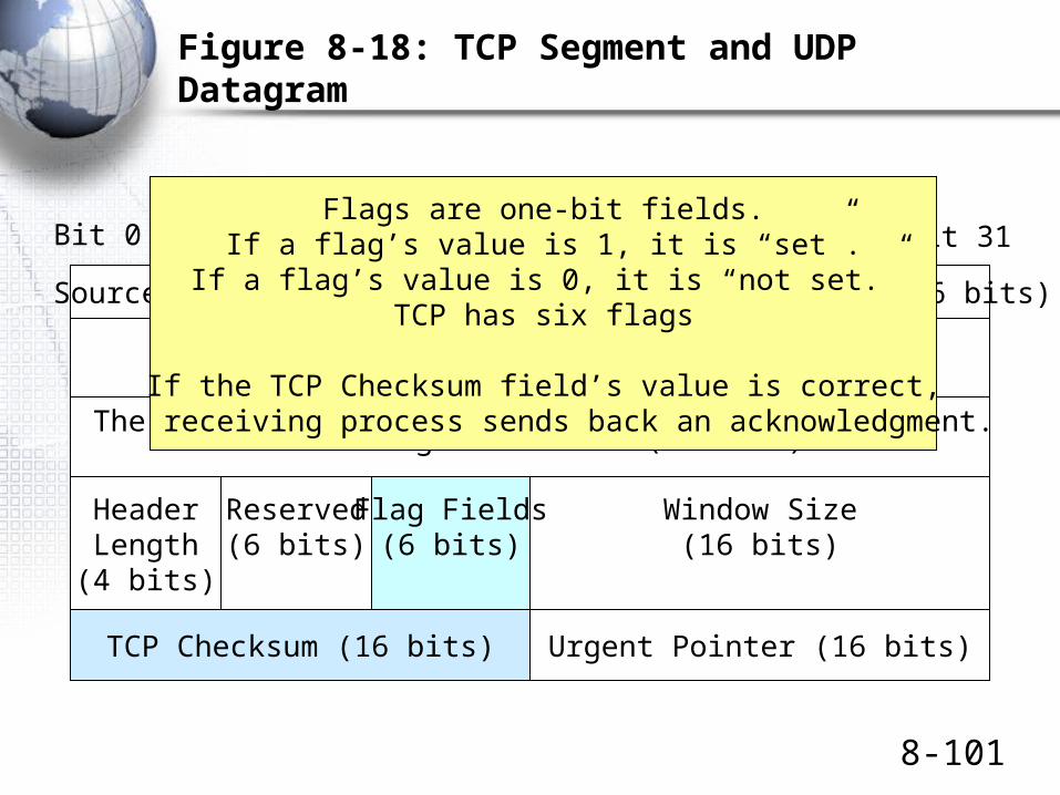
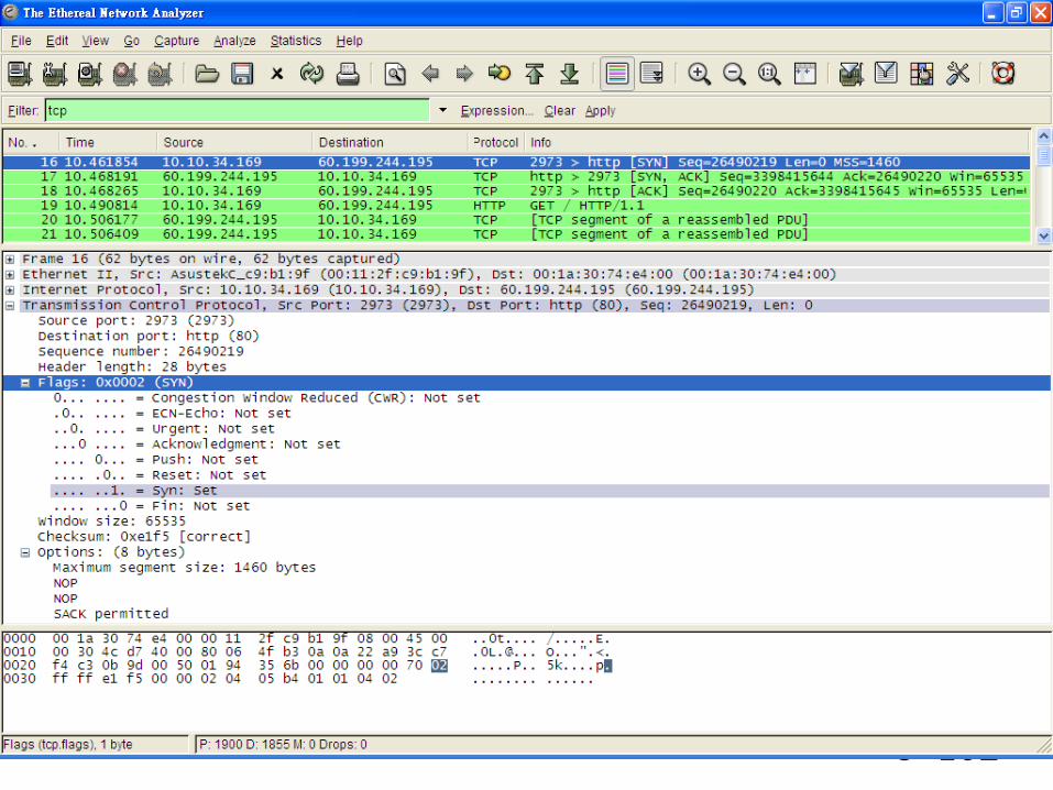
Flags are one-bit fields.If a flag’s value is 1, it is “set”.
If a flag’s value is 0, it is “not set.”TCP has six flags
If the TCP Checksum field’s value is correct,The receiving process sends back an acknowledgment.
8-102
8-103
Figure 8-18: TCP Segment and UDP Datagram
TCP Segment
Window Size(16 bits)
Bit 0 Bit 31
Destination Port Number (16 bits)Source Port Number (16 bits)
Sequence Number (32 bits)
Acknowledgment Number (32 bits)
Urgent Pointer (16 bits)TCP Checksum (16 bits)
HeaderLength(4 bits)
Reserved(6 bits)
Flag Fields(6 bits)
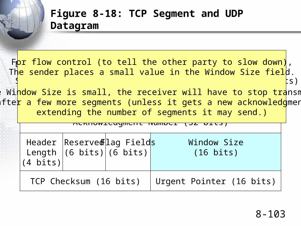
For flow control (to tell the other party to slow down),The sender places a small value in the Window Size field.
If the Window Size is small, the receiver will have to stop transmittingafter a few more segments (unless it gets a new acknowledgment
extending the number of segments it may send.)

8-104
Figure 8-18: TCP Segment and UDP Datagram
TCP SegmentBit 0 Bit 31
PaddingOptions (if any)
Data Field
TCP segment headers can end with options.This is very common.
If an option does not end at a 32-bit boundary,padding must be added.

The User Datagram Protocol (UDP)
8-106
Figure 8-18: TCP Segment and UDP Datagram
UDP DatagramBit 0 Bit 31
Source Port Number (16 bits) Destination Port Number (16 bits)
UDP Length (16 bits) UDP Checksum (16 bits)
Data Field
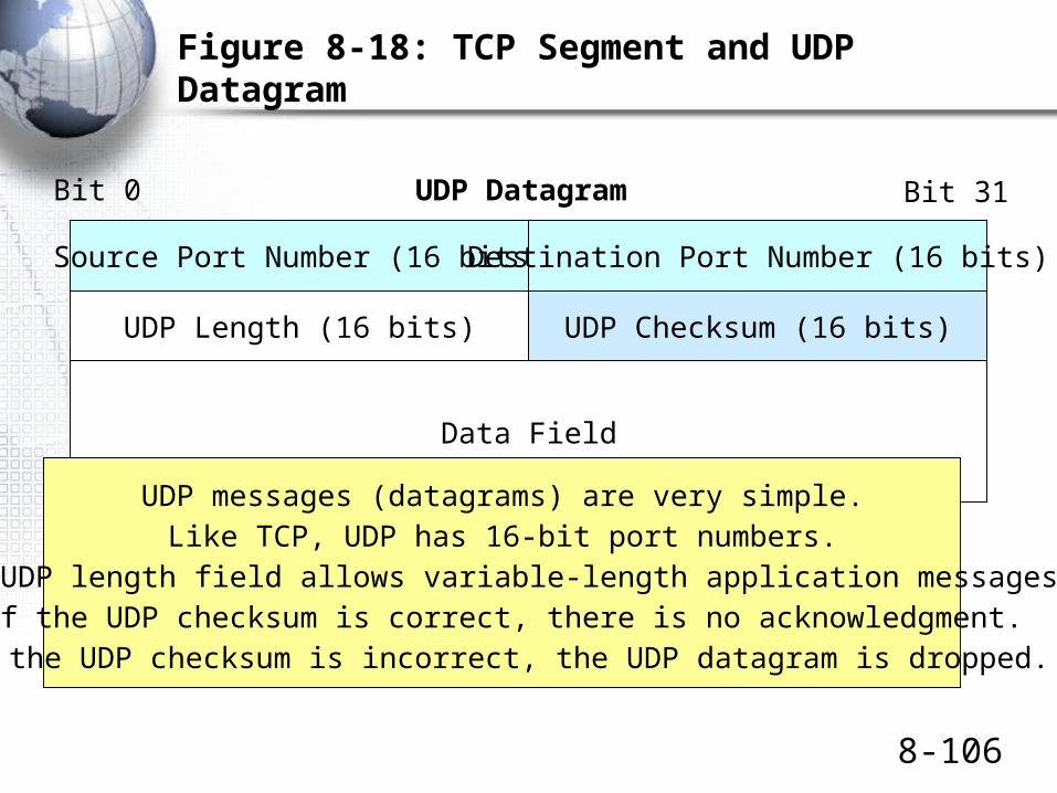
UDP messages (datagrams) are very simple.Like TCP, UDP has 16-bit port numbers.
The UDP length field allows variable-length application messages.If the UDP checksum is correct, there is no acknowledgment.
If the UDP checksum is incorrect, the UDP datagram is dropped.

8-107
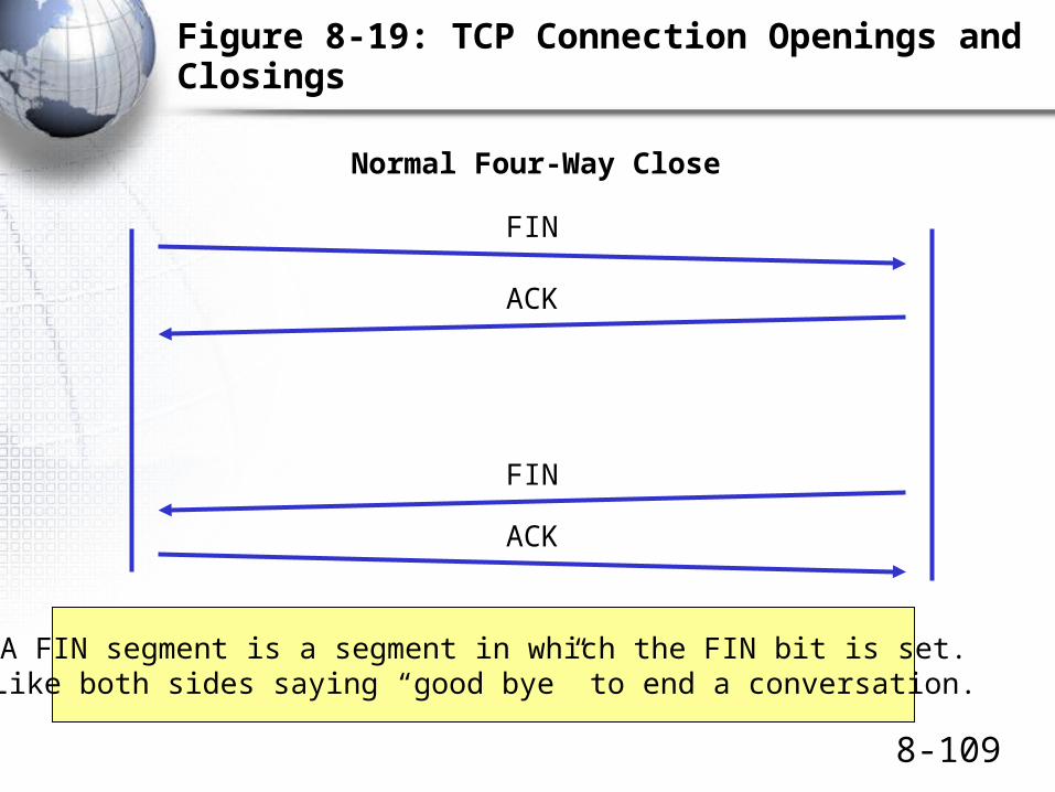
Figure 8-19: TCP Connection Openings and Closings
• TCP is a connection-oriented protocol
– Each connection has a formal opening process
– Each connection has a formal closing process
– During a connection, each TCP segment is acknowledged
• (Of course, pure acknowledgments are not acknowledged)

8-108
Figure 8-19: TCP Connection Openings and Closings
SYN
SYN/ACK
ACK
Normal Three-Way Opening
A SYN segment is a segment in which the SYN bit is set.One side sends a SYN segment requesting an opening.The other side sends a SYN/acknowledgment segment.
Originating side acknowledges the SYN/ACK.
8-109
Figure 8-19: TCP Connection Openings and Closings
FIN
ACK
FIN
ACK
Normal Four-Way Close
A FIN segment is a segment in which the FIN bit is set.Like both sides saying “good bye” to end a conversation.

8-110
Figure 8-19: TCP Connection Openings and Closings
RST
Abrupt Reset
An RST segment is a segment in which the RST bit is set.A single RST segment breaks a connection.
Like hanging up during a phone call.There is no acknowledgment.

Port Numbers and Sockets in TCP and UDP
8-112
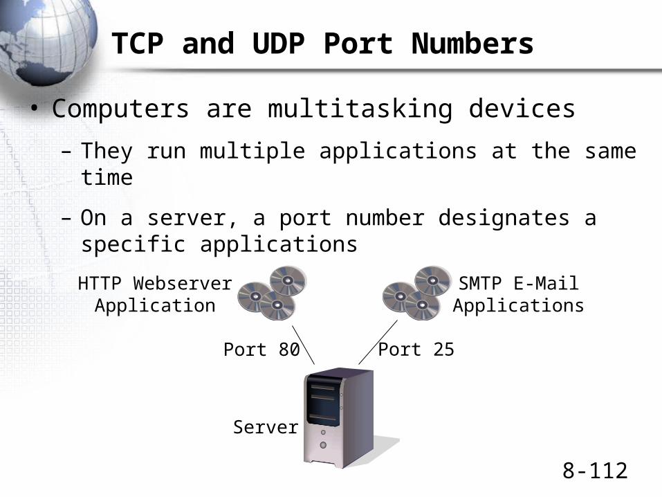
TCP and UDP Port Numbers
• Computers are multitasking devices
– They run multiple applications at the same time
– On a server, a port number designates a specific applications
Server
HTTP WebserverApplication
SMTP E-MailApplications
Port 80 Port 25
8-113
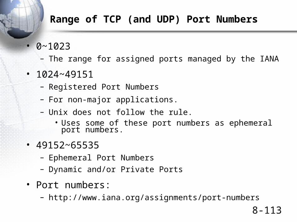
Range of TCP (and UDP) Port Numbers
• 0~1023– The range for assigned ports managed by the IANA
• 1024~49151– Registered Port Numbers
– For non-major applications.
– Unix does not follow the rule.• Uses some of these port numbers as ephemeral port
numbers.
• 49152~65535– Ephemeral Port Numbers– Dynamic and/or Private Ports
• Port numbers:– http://www.iana.org/assignments/port-numbers
8-114
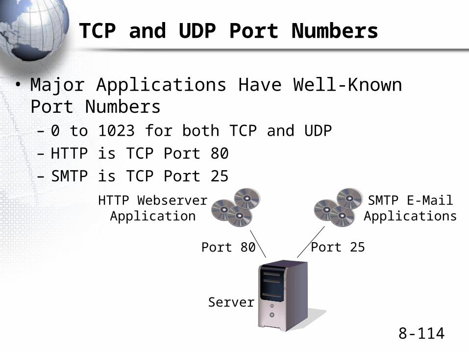
TCP and UDP Port Numbers
• Major Applications Have Well-Known Port Numbers– 0 to 1023 for both TCP and UDP– HTTP is TCP Port 80– SMTP is TCP Port 25
Server
HTTP WebserverApplication
SMTP E-MailApplications
Port 80 Port 25

8-115
TCP and UDP Port Numbers
• Clients Use Ephemeral Port Numbers– 1024 to 4999 for Windows Client PCs– A client has a separate port number for each connection
to a program on a webserver
Client
Port 4400 Port 3270
WebserverApplication
on Webserver
E-MailApplication
on MailServer

8-116
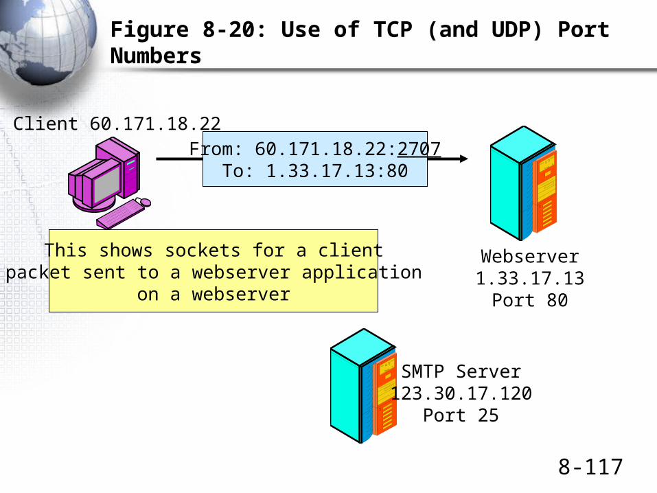
Figure 8-20: Use of TCP (and UDP) Port Numbers
Client 60.171.18.22
Webserver1.33.17.13
Port 80
SMTP Server123.30.17.120
Port 25
A socket is anIP address, a colon, and a port number.
1.33.17.3:80123.30.17.120:25
128.171.17.13:2849
It represents a specific application (Port number)on a specific server (IP address)
Or a specific connection on a client.
Client PC128.171.17.13
Port 2849
8-117
Figure 8-20: Use of TCP (and UDP) Port Numbers
Client 60.171.18.22
Webserver1.33.17.13
Port 80
From: 60.171.18.22:2707To: 1.33.17.13:80
SMTP Server123.30.17.120
Port 25
This shows sockets for a clientpacket sent to a webserver application
on a webserver

8-118
Figure 8-20: Use of TCP (and UDP) Port Numbers
Client 60.171.18.22
Webserver1.33.17.13
Port 80
From: 60.171.18.22:2707To: 1.33.17.13:80
From: 1.33.17.13:80To: 60.171.18.22:2707
SMTP Server123.30.17.120
Port 25
Sockets intwo-way
transmission
8-119
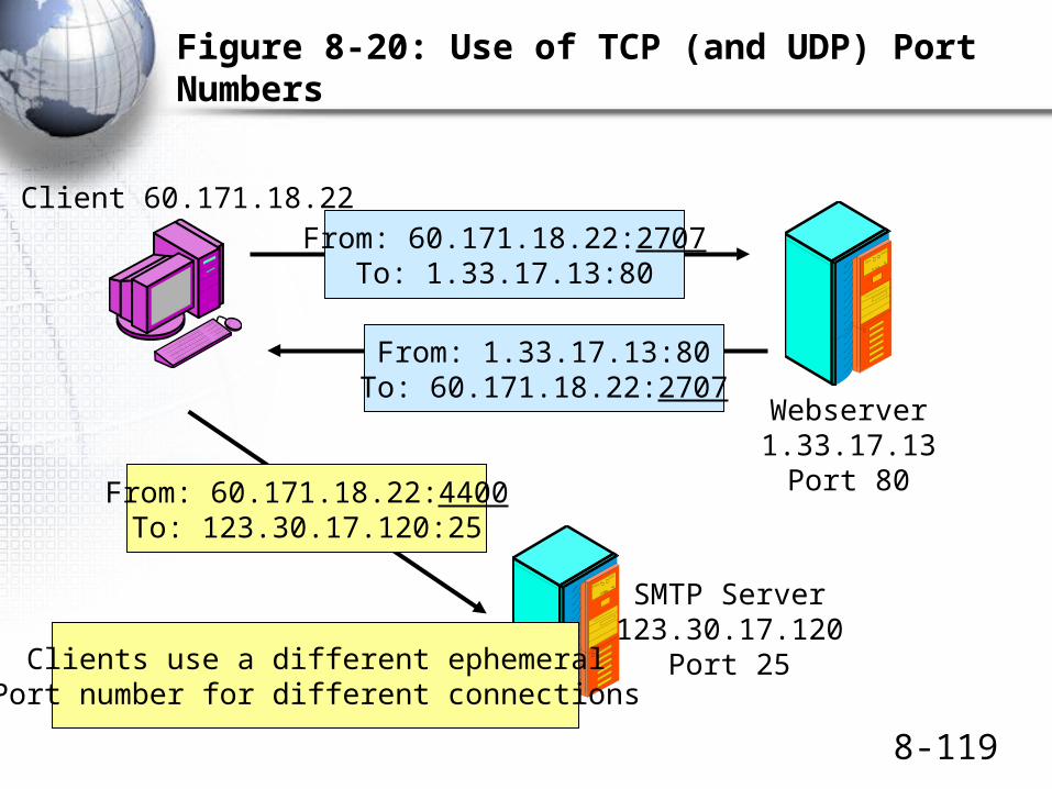
Figure 8-20: Use of TCP (and UDP) Port Numbers
Client 60.171.18.22
Webserver1.33.17.13
Port 80
From: 60.171.18.22:2707To: 1.33.17.13:80
From: 1.33.17.13:80To: 60.171.18.22:2707
From: 60.171.18.22:4400To: 123.30.17.120:25
SMTP Server123.30.17.120
Port 25Clients use a different ephemeralPort number for different connections
Layer 3 Switches

8-121
Figure 8-21: Layer 3 Switches and Routers in Site Networks
Router
Ethernet WorkgroupSwitch
ToOtherSites
Layer 3Switch
L3
L3
Layer 3 switches arerouters.
Layer 3 switches arefaster and cheaper tobuy than traditionalrouters.
However, they areusually limited infunctionality.
They also areexpensive to manage.
They are typicallyused between
Figure 8-21: Layer 3 Switches and Routers in Site Internets
Ethernet WorkgroupSwitch
Layer 3Switch
Usually too expensive to replace workgroup switches.Usually too limited in functionality to replace border routers.
Replaces core switches in the middle.

Topics Covered

8-123
Topics Covered
• Internetworking Recap from Earlier Chapters
– Internetworking involves the internet and transport layers
– Packets are encapsulated in frames in single networks.
– Transport layer is end-to-end
– Internet layer is hop-by-hop between routers
– IP, TCP, and UDP are the heart of TCP/IP internetworking
8-124
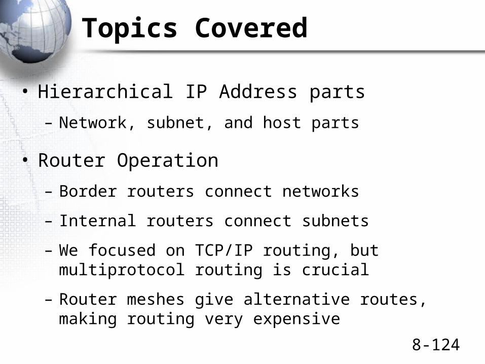
Topics Covered
• Hierarchical IP Address parts
– Network, subnet, and host parts
• Router Operation
– Border routers connect networks
– Internal routers connect subnets
– We focused on TCP/IP routing, but multiprotocol routing is crucial
– Router meshes give alternative routes, making routing very expensive

8-125
Topics Covered
• Routing of Packets• Routing tables
• IP address range governed by a row—usually a route to a network or subnet
• Metric to help select best matches
• Next-hop router to be sent the packet next– Can be a local host on one of the router’s subnets
– Process
• Final all possible routes through row matching
• Select by length of match, then metric if tie
• Send out to next-hop router in the best-match row
8-126
Topics Covered
• Detailed Look at Routing Decisions
• IP address range– Destination– Mask– If the masked destination IP address in an arriving
packet matches the destination value, the row is a match
• Next-Hop Router– Interface– Next-hop router or destination host
Box
8-127
Topics Covered
• Dynamic Routing Protocols• Interior dynamic routing protocols within an
autonomous system– RIP, OSPF, EIGRP
• Exterior dynamic routing protocols between autonomous systems
– BGP
• Address Resolution Protocol
– Router knows the IP address of the next-hop router or destination host
– Must learn the data link layer address as well
8-128
Topics Covered
• Multiprotocol Label Switching– Routing decisions are based on labels rather than
destination IP addresses
– Reduces routing costs
• Domain Name System (DNS)– General hierarchical naming system for the Internet
• Internet Control Message Protocol (ICMP)
– General supervisory protocol at the internet layer
– Error advisements and Pings (echo requests/replies)

8-129
Topics Covered
• The Internet Protocol (IP)
– Detailed look at key fields
– Protocol field lists contents of the data field
– 32-bit IP addresses
– IPv4 is the current version
– IPv6 offers 128-bit IP addresses to allow many more IP addresses to serve the world
8-130
Topics Covered
• The Transmission Control Protocol (TCP)
– Sequence and acknowledgement numbers
– Flag fields that are set or not set
– Window size field allows flow control
– Options are common
– Three-way openings (SYN, SYN/ACK, and ACK)
– Four-way normal closings (FIN, ACK, FIN, ACK)
– One-way abrupt closing (RST)
8-131
Topics Covered
• The User Datagram Protocol (UDP)– Simple four-field header
• Port Numbers and Sockets in TCP and UDP– Applications get well-known port numbers on servers
– Connections get ephemeral port numbers on clients
– Socket is an IP address, a colon, and a port number
– This designates a specific application (or connection) on a specific server (or client)
• Layer 3 Switches– Fast, inexpensive, and limited routers