Embed Size (px)
Citation preview
8/10/2019 TCSM COMMAND.pdf
http://slidepdf.com/reader/full/tcsm-commandpdf 1/125
Nokia Siemens Networks
GSM/EDGE BSS, rel.
RG20(BSS), operatingdocumentation, issue 02
Reference
TCSM2 User Commands
DN98513282
Issue 8-0
Confidential
8/10/2019 TCSM COMMAND.pdf
http://slidepdf.com/reader/full/tcsm-commandpdf 2/125
2 DN98513282
Issue 8-0
TCSM2 User Commands
Id:0900d805805a29eb
Confidential
The information in this document is subject to change without notice and describes only the
product defined in the introduction of this documentation. This documentation is intended for the
use of Nokia Siemens Networks customers only for the purposes of the agreement under whichthe document is submitted, and no part of it may be used, reproduced, modified or transmitted
in any form or means without the prior written permission of Nokia Siemens Networks. The
documentation has been prepared to be used by professional and properly trained personnel,
and the customer assumes full responsibility when using it. Nokia Siemens Networks welcomes
customer comments as part of the process of continuous development and improvement of the
documentation.
The information or statements given in this documentation concerning the suitability, capacity,
or performance of the mentioned hardware or software products are given "as is" and all liability
arising in connection with such hardware or software products shall be defined conclusively and
finally in a separate agreement between Nokia Siemens Networks and the customer. However,
Nokia Siemens Networks has made all reasonable efforts to ensure that the instructions
contained in the document are adequate and free of material errors and omissions. Nokia
Siemens Networks will, if deemed necessary by Nokia Siemens Networks, explain issues which
may not be covered by the document.
Nokia Siemens Networks will correct errors in this documentation as soon as possible. IN NO
EVENT WILL Nokia Siemens Networks BE LIABLE FOR ERRORS IN THIS DOCUMENTA-
TION OR FOR ANY DAMAGES, INCLUDING BUT NOT LIMITED TO SPECIAL, DIRECT, INDI-
RECT, INCIDENTAL OR CONSEQUENTIAL OR ANY LOSSES, SUCH AS BUT NOT LIMITED
TO LOSS OF PROFIT, REVENUE, BUSINESS INTERRUPTION, BUSINESS OPPORTUNITY
OR DATA,THAT MAY ARISE FROM THE USE OF THIS DOCUMENT OR THE INFORMATION
IN IT.
This documentation and the product it describes are considered protected by copyrights and
other intellectual property rights according to the applicable laws.
The wave logo is a trademark of Nokia Siemens Networks Oy. Nokia is a registered trademark
of Nokia Corporation. Siemens is a registered trademark of Siemens AG.
Other product names mentioned in this document may be trademarks of their respectiveowners, and they are mentioned for identification purposes only.
Copyright © Nokia Siemens Networks 2010. All rights reserved
f Important Notice on Product SafetyElevated voltages are inevitably present at specific points in this electrical equipment.
Some of the parts may also have elevated operating temperatures.
Non-observance of these conditions and the safety instructions can result in personal
injury or in property damage.
Therefore, only trained and qualified personnel may install and maintain the system.
The system complies with the standard EN 60950 / IEC 60950. All equipment connected
has to comply with the applicable safety standards.
The same text in German:
Wichtiger Hinweis zur Produktsicherheit
In elektrischen Anlagen stehen zwangsläufig bestimmte Teile der Geräte unter Span-
nung. Einige Teile können auch eine hohe Betriebstemperatur aufweisen.
Eine Nichtbeachtung dieser Situation und der Warnungshinweise kann zu Körperverlet-
zungen und Sachschäden führen.
Deshalb wird vorausgesetzt, dass nur geschultes und qualifiziertes Personal die
Anlagen installiert und wartet.
Das System entspricht den Anforderungen der EN 60950 / IEC 60950. Angeschlossene
Geräte müssen die zutreffenden Sicherheitsbestimmungen erfüllen.
8/10/2019 TCSM COMMAND.pdf
http://slidepdf.com/reader/full/tcsm-commandpdf 3/125
DN98513282
Issue 8-0
3
TCSM2 User Commands
Id:0900d805805a29eb
Confidential
Table of contentsThis document has 125 pages.
Summary of changes . . . . . . . . . . . . . . . . . . . . . . . . . . . . . . . . . . . . . . . . 9
1 Overview of TCSM2 user commands . . . . . . . . . . . . . . . . . . . . . . . . . . 10
2 Introduction to TCSM2 functions . . . . . . . . . . . . . . . . . . . . . . . . . . . . . . 13
3 Getting started . . . . . . . . . . . . . . . . . . . . . . . . . . . . . . . . . . . . . . . . . . . . 15
3.1 Session priority . . . . . . . . . . . . . . . . . . . . . . . . . . . . . . . . . . . . . . . . . . . 15
3.2 Starting and ending a local session. . . . . . . . . . . . . . . . . . . . . . . . . . . . 15
3.3 Starting and ending a remote session through the BSC . . . . . . . . . . . . 16
3.4 Menu commands . . . . . . . . . . . . . . . . . . . . . . . . . . . . . . . . . . . . . . . . . . 16
4 TCSM2 commands . . . . . . . . . . . . . . . . . . . . . . . . . . . . . . . . . . . . . . . . 18
4.1 A: Alarm handling commands . . . . . . . . . . . . . . . . . . . . . . . . . . . . . . . . 22
4.1.1 AI: Display alarms currently on . . . . . . . . . . . . . . . . . . . . . . . . . . . . . . . 23
4.1.2 AW: Wired alarms from other TCSM2 units. . . . . . . . . . . . . . . . . . . . . . 23
4.1.3 AF: Far end alarm handling . . . . . . . . . . . . . . . . . . . . . . . . . . . . . . . . . . 24
4.2 C: Diagnostics commands. . . . . . . . . . . . . . . . . . . . . . . . . . . . . . . . . . . 25
4.2.1 CC: Start complete diagnostics . . . . . . . . . . . . . . . . . . . . . . . . . . . . . . . 25
4.2.2 CM: Start memory test. . . . . . . . . . . . . . . . . . . . . . . . . . . . . . . . . . . . . . 27
4.2.3 CH: Start HDLC controller test. . . . . . . . . . . . . . . . . . . . . . . . . . . . . . . . 27
4.2.4 CT: Start loop tests . . . . . . . . . . . . . . . . . . . . . . . . . . . . . . . . . . . . . . . . 28
4.2.5 CE: Start Exchange Terminal test . . . . . . . . . . . . . . . . . . . . . . . . . . . . . 30
4.2.6 CO: Display diagnostics results . . . . . . . . . . . . . . . . . . . . . . . . . . . . . . . 31
4.2.7 CS: Display LAPD channel states . . . . . . . . . . . . . . . . . . . . . . . . . . . . . 33
4.2.8 CG: Set loops for PCM circuit . . . . . . . . . . . . . . . . . . . . . . . . . . . . . . . . 33
4.2.9 CL: Set loops for traffic channels. . . . . . . . . . . . . . . . . . . . . . . . . . . . . . 35
4.2.10 CD: Display loops . . . . . . . . . . . . . . . . . . . . . . . . . . . . . . . . . . . . . . . . . 37
4.2.11 CR: Remove loops. . . . . . . . . . . . . . . . . . . . . . . . . . . . . . . . . . . . . . . . . 38
4.3 L: Synchronisation commands. . . . . . . . . . . . . . . . . . . . . . . . . . . . . . . . 39
4.3.1 LS: Display synchronisation inputs . . . . . . . . . . . . . . . . . . . . . . . . . . . . 39
4.3.2 LC: Create synchronisation input. . . . . . . . . . . . . . . . . . . . . . . . . . . . . . 40
4.3.3 LD: Delete synchronisation input . . . . . . . . . . . . . . . . . . . . . . . . . . . . . . 40
4.3.4 LP: Change synchronisation input priority . . . . . . . . . . . . . . . . . . . . . . . 41
4.3.5 LF: Change synchronisation input . . . . . . . . . . . . . . . . . . . . . . . . . . . . . 424.3.6 LO: Set synchronisation block operating mode . . . . . . . . . . . . . . . . . . . 43
4.4 G: General configuration commands . . . . . . . . . . . . . . . . . . . . . . . . . . . 44
4.4.1 GT: Display TCSM2 hardware configuration . . . . . . . . . . . . . . . . . . . . . 44
4.4.2 GI: Display program identification codes . . . . . . . . . . . . . . . . . . . . . . . . 46
4.4.3 GL: Set PCM line terminal type . . . . . . . . . . . . . . . . . . . . . . . . . . . . . . . 47
4.4.4 GH: Set through connected channels . . . . . . . . . . . . . . . . . . . . . . . . . . 48
4.4.5 GU: Update software in flash memory. . . . . . . . . . . . . . . . . . . . . . . . . . 49
4.4.6 GW: Display transcoder software . . . . . . . . . . . . . . . . . . . . . . . . . . . . . 51
4.4.7 GS: Save configuration . . . . . . . . . . . . . . . . . . . . . . . . . . . . . . . . . . . . . 51
4.4.8 GN: Download configuration from PC . . . . . . . . . . . . . . . . . . . . . . . . . . 52
4.4.9 GO: Upload configuration to PC . . . . . . . . . . . . . . . . . . . . . . . . . . . . . . 53
8/10/2019 TCSM COMMAND.pdf
http://slidepdf.com/reader/full/tcsm-commandpdf 4/125
4 DN98513282
Issue 8-0
TCSM2 User Commands
Id:0900d805805a29eb
Confidential
4.4.10 GV: Set HW identification . . . . . . . . . . . . . . . . . . . . . . . . . . . . . . . . . . . . 53
4.4.11 GP: Change password . . . . . . . . . . . . . . . . . . . . . . . . . . . . . . . . . . . . . . 54
4.4.12 GC: Set default configuration . . . . . . . . . . . . . . . . . . . . . . . . . . . . . . . . . 54
4.5 R: Transcoder configuration commands. . . . . . . . . . . . . . . . . . . . . . . . . 554.5.1 RC: Display channel configuration . . . . . . . . . . . . . . . . . . . . . . . . . . . . . 55
4.5.2 RX: Set downlink DTX . . . . . . . . . . . . . . . . . . . . . . . . . . . . . . . . . . . . . . 60
4.5.3 RA: Set adaptive gain adjustment in the downlink direction . . . . . . . . . . 61
4.5.4 RF: Set fixed gain adjustment. . . . . . . . . . . . . . . . . . . . . . . . . . . . . . . . . 63
4.5.5 RS: Set time alignment . . . . . . . . . . . . . . . . . . . . . . . . . . . . . . . . . . . . . . 64
4.5.6 RU: Set Acoustic Echo Cancellation (AEC) . . . . . . . . . . . . . . . . . . . . . . 65
4.5.7 RN: Set Tandem Free Operation (TFO) . . . . . . . . . . . . . . . . . . . . . . . . . 68
4.5.8 RY: Set Noise Suppression (NS) . . . . . . . . . . . . . . . . . . . . . . . . . . . . . . 70
4.5.9 RM: Start traffic channel monitoring . . . . . . . . . . . . . . . . . . . . . . . . . . . . 73
4.5.10 RT: Modify alarm limits . . . . . . . . . . . . . . . . . . . . . . . . . . . . . . . . . . . . . . 74
4.5.11 RO: Display alarm limits . . . . . . . . . . . . . . . . . . . . . . . . . . . . . . . . . . . . . 754.5.12 RR: Set transcoder PCM types. . . . . . . . . . . . . . . . . . . . . . . . . . . . . . . . 76
4.5.13 RD: Display transcoder PCM types . . . . . . . . . . . . . . . . . . . . . . . . . . . . 77
4.6 E: Exchange Terminal supervision commands. . . . . . . . . . . . . . . . . . . . 78
4.6.1 EM: Modify ET parameters . . . . . . . . . . . . . . . . . . . . . . . . . . . . . . . . . . . 79
4.6.2 EO: Display ET parameters . . . . . . . . . . . . . . . . . . . . . . . . . . . . . . . . . . 80
4.6.3 EA: Modify alarm limits . . . . . . . . . . . . . . . . . . . . . . . . . . . . . . . . . . . . . . 81
4.6.4 EP: Display alarm limits . . . . . . . . . . . . . . . . . . . . . . . . . . . . . . . . . . . . . 83
4.6.5 ES: Modify statistics counters limits . . . . . . . . . . . . . . . . . . . . . . . . . . . . 84
4.6.6 EL: Display statistics counters limits. . . . . . . . . . . . . . . . . . . . . . . . . . . . 85
4.6.7 EU: Modify slip limits. . . . . . . . . . . . . . . . . . . . . . . . . . . . . . . . . . . . . . . . 86
4.6.8 ER: Display slip limits . . . . . . . . . . . . . . . . . . . . . . . . . . . . . . . . . . . . . . . 87
4.6.9 EC: Modify functional mode – ETSI mode . . . . . . . . . . . . . . . . . . . . . . . 88
4.6.10 EC: Modify functional mode – ANSI mode . . . . . . . . . . . . . . . . . . . . . . . 89
4.6.11 EC: Modify functional mode – ANSI-C mode . . . . . . . . . . . . . . . . . . . . . 90
4.6.12 EI: Display functional modes. . . . . . . . . . . . . . . . . . . . . . . . . . . . . . . . . . 92
4.7 ZU: Unit restart and state handling commands. . . . . . . . . . . . . . . . . . . . 93
4.7.1 UC: Change TCSM2 unit state . . . . . . . . . . . . . . . . . . . . . . . . . . . . . . . . 93
4.7.2 UU: Restart TCSM2 unit . . . . . . . . . . . . . . . . . . . . . . . . . . . . . . . . . . . . . 94
4.7.3 UP: Restart plug-in unit. . . . . . . . . . . . . . . . . . . . . . . . . . . . . . . . . . . . . . 95
4.7.4 UB: Block plug-in unit . . . . . . . . . . . . . . . . . . . . . . . . . . . . . . . . . . . . . . . 95
4.7.5 UF: Unblock plug-in unit . . . . . . . . . . . . . . . . . . . . . . . . . . . . . . . . . . . . . 964.8 I: Statistics commands . . . . . . . . . . . . . . . . . . . . . . . . . . . . . . . . . . . . . . 97
4.8.1 IF: Display PCM fault rate counters . . . . . . . . . . . . . . . . . . . . . . . . . . . . 97
4.8.2 IR: Reset PCM fault rate counters . . . . . . . . . . . . . . . . . . . . . . . . . . . . . 99
4.8.3 IU: Display Exchange Terminal reset counters. . . . . . . . . . . . . . . . . . . 100
4.8.4 IP: Reset Exchange Terminal reset counters . . . . . . . . . . . . . . . . . . . . 100
4.8.5 IT: Display transcoder reset counters . . . . . . . . . . . . . . . . . . . . . . . . . . 101
4.8.6 IC: Reset transcoder reset counters . . . . . . . . . . . . . . . . . . . . . . . . . . . 101
4.9 D: Memory and I/O handling commands . . . . . . . . . . . . . . . . . . . . . . . 102
4.9.1 DC: Display memory block continuously. . . . . . . . . . . . . . . . . . . . . . . . 103
4.9.2 DD: Display memory block . . . . . . . . . . . . . . . . . . . . . . . . . . . . . . . . . . 103
4.9.3 DE: Search for a string . . . . . . . . . . . . . . . . . . . . . . . . . . . . . . . . . . . . . 104
8/10/2019 TCSM COMMAND.pdf
http://slidepdf.com/reader/full/tcsm-commandpdf 5/125
DN98513282
Issue 8-0
5
TCSM2 User Commands
Id:0900d805805a29eb
Confidential
4.9.4 DF: Fill memory block . . . . . . . . . . . . . . . . . . . . . . . . . . . . . . . . . . . . . 104
4.9.5 DI: Input port . . . . . . . . . . . . . . . . . . . . . . . . . . . . . . . . . . . . . . . . . . . . 105
4.9.6 DM: Move memory block. . . . . . . . . . . . . . . . . . . . . . . . . . . . . . . . . . . 105
4.9.7 DO: Output port . . . . . . . . . . . . . . . . . . . . . . . . . . . . . . . . . . . . . . . . . . 1064.9.8 DP: Memory block check sum . . . . . . . . . . . . . . . . . . . . . . . . . . . . . . . 107
4.9.9 DS: Substitute memory . . . . . . . . . . . . . . . . . . . . . . . . . . . . . . . . . . . . 107
4.9.10 DV: Memory block comparation. . . . . . . . . . . . . . . . . . . . . . . . . . . . . . 108
4.10 O: Operating system commands . . . . . . . . . . . . . . . . . . . . . . . . . . . . . 109
4.10.1 OC: Create process. . . . . . . . . . . . . . . . . . . . . . . . . . . . . . . . . . . . . . . 109
4.10.2 OD: Destroy process . . . . . . . . . . . . . . . . . . . . . . . . . . . . . . . . . . . . . . 110
4.10.3 OG: Change priority . . . . . . . . . . . . . . . . . . . . . . . . . . . . . . . . . . . . . . . 110
4.10.4 OH: Display process PCB . . . . . . . . . . . . . . . . . . . . . . . . . . . . . . . . . . 111
4.10.5 OM: Display process state. . . . . . . . . . . . . . . . . . . . . . . . . . . . . . . . . . 112
4.10.6 OP: P-Operation . . . . . . . . . . . . . . . . . . . . . . . . . . . . . . . . . . . . . . . . . 113
4.10.7 OR: Receive message. . . . . . . . . . . . . . . . . . . . . . . . . . . . . . . . . . . . . 1134.10.8 OS: Send message . . . . . . . . . . . . . . . . . . . . . . . . . . . . . . . . . . . . . . . 114
4.10.9 OT: Test if messages coming . . . . . . . . . . . . . . . . . . . . . . . . . . . . . . . 115
4.10.10 OU: Restart process . . . . . . . . . . . . . . . . . . . . . . . . . . . . . . . . . . . . . . 116
4.10.11 OV: V-Operation . . . . . . . . . . . . . . . . . . . . . . . . . . . . . . . . . . . . . . . . . 116
4.11 S: System monitoring commands . . . . . . . . . . . . . . . . . . . . . . . . . . . . 117
4.11.1 SC: Pectus error counters . . . . . . . . . . . . . . . . . . . . . . . . . . . . . . . . . . 117
4.11.2 SL: Processor load rate . . . . . . . . . . . . . . . . . . . . . . . . . . . . . . . . . . . . 118
4.11.3 SS: Calculate and compare check sums . . . . . . . . . . . . . . . . . . . . . . . 118
4.11.4 SX: Examine program identification codes . . . . . . . . . . . . . . . . . . . . . 119
4.12 T: Set and display terminal . . . . . . . . . . . . . . . . . . . . . . . . . . . . . . . . . 122
5 Error messages in TCSM2 user commands . . . . . . . . . . . . . . . . . . . . 123
6 Additional information to TCSM2 user commands. . . . . . . . . . . . . . . . 124
8/10/2019 TCSM COMMAND.pdf
http://slidepdf.com/reader/full/tcsm-commandpdf 6/125
6 DN98513282
Issue 8-0
TCSM2 User Commands
Id:0900d805805a29eb
Confidential
List of figuresFigure 1 Command example. . . . . . . . . . . . . . . . . . . . . . . . . . . . . . . . . . . . . . . . . 11
Figure 2 Operating environment of the TCSM2 . . . . . . . . . . . . . . . . . . . . . . . . . . 13
Figure 3 Cable connections . . . . . . . . . . . . . . . . . . . . . . . . . . . . . . . . . . . . . . . . 125
8/10/2019 TCSM COMMAND.pdf
http://slidepdf.com/reader/full/tcsm-commandpdf 7/125
DN98513282
Issue 8-0
7
TCSM2 User Commands
Id:0900d805805a29eb
Confidential
List of tablesTable 1 Typographic conventions . . . . . . . . . . . . . . . . . . . . . . . . . . . . . . . . . . . 11
Table 2 The use of diagnostics commands. . . . . . . . . . . . . . . . . . . . . . . . . . . . 25
Table 3 Channel states. . . . . . . . . . . . . . . . . . . . . . . . . . . . . . . . . . . . . . . . . . . . 59
8/10/2019 TCSM COMMAND.pdf
http://slidepdf.com/reader/full/tcsm-commandpdf 8/125
8 DN98513282
Issue 8-0
TCSM2 User Commands
Id:0900d805805a29eb
Confidential
8/10/2019 TCSM COMMAND.pdf
http://slidepdf.com/reader/full/tcsm-commandpdf 9/125
DN98513282
Issue 8-0
9
TCSM2 User Commands Summary of changes
Id:0900d805805a29d6
Confidential
Summary of changesChanges between document issues are cumulative. Therefore, the latest document
issue contains all changes made to previous issues.
Changes made between issues 8-0 and 7-0
Editorial changes. No effect on the contents of the document.
Changes made between issues 7-0 and 6-3
The document has been modularized. No content changes were made.
Changes made between issues 6-3 and 6-2
The document structure and links have been corrected to fit the online requirements. No
content changes were made.
8/10/2019 TCSM COMMAND.pdf
http://slidepdf.com/reader/full/tcsm-commandpdf 10/125
10 DN98513282
Issue 8-0
TCSM2 User Commands
Id:0900d805805a29d9
Confidential
Overview of TCSM2 user commands
1 Overview of TCSM2 user commandsThis section describes how to configure and operate the TCSM2 unit through a local or
remote session, using the menu commands available.
How to use this manual
This manual provides the following information:
• Introduction
• Getting started
• A detailed reference chapter which describes the menus and commands
• Error messages in TCSM2 user commands
• Alarm list
• Cable connections
Where to find more
For information on the initial start-up procedures, see the TCSM2 Commissioning .
The BSC manuals cover specific uses related to the TCSM2. Consult the GSM System
Documentation for a description of the BSC manuals.
Use of the terms TCSM2, TCSM2E, TCSM2A and TCSM2A-C
TCSM2 is the general term for the second generation Nokia DX 200 Transcoder and
Submultiplexer equipment. TCSM2A stands for an ANSI (US) version and TCSM2E for
an ETSI (European) version of the transcoder. Further, TCSM2A-C stands for the ANSI
version in special cases where the TCSM2A is provided with an E1 interface (2048
kbit/s) towards the Mobile Switching Center (MSC). The term TCSM2 is used in this
document to stand for all three applications. Note that the term is used in two ways: • TCSM2 unit: the unit (group of cartridges and their plug-in units) responsible for
transcoding and submultiplexing the traffic channels carried by a single PCM line
between the BSC and the transcoding site.
• TCSM2 equipment: the assembly of racks housing the TCSM2 units of one or more
BSCs.
Use of PCM/T1/E1
The term PCM circuit used in the menus stands for a T1 circuit for ANSI applications
(TCSM2A) and an E1 circuit for ETSI applications (TCSM2E). A T1 circuit is a 1.544
Mbit/s metallic interface which corresponds to a 2.048 Mbit/s E1 circuit. In TCSM2A-C
application, E1 circuits are used in the MSC direction and T1 circuits in the BSC direc-tion.
Typographic conventions
Transition from one menu to another is performed with the command Z and the main
level commands, or by giving a command of any menu directly in any menu as in the
following example:
8/10/2019 TCSM COMMAND.pdf
http://slidepdf.com/reader/full/tcsm-commandpdf 11/125
DN98513282
Issue 8-0
11
TCSM2 User Commands Overview of TCSM2 user commands
Id:0900d805805a29d9
Confidential
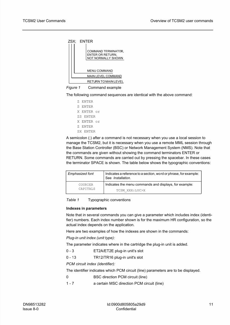
Figure 1 Command example
The following command sequences are identical with the above command:
Z ENTER
S ENTER
X ENTER or
ZS ENTER
X ENTER or
Z ENTER
SX ENTER
A semicolon (;) after a command is not necessary when you use a local session to
manage the TCSM2, but it is necessary when you use a remote MML session through
the Base Station Controller (BSC) or Network Management System (NMS). Note that
the commands are given without showing the command terminators ENTER or
RETURN. Some commands are carried out by pressing the spacebar. In these cases
the terminator SPACE is shown. The table below shows the typographic conventions:
Indexes in parameters
Note that in several commands you can give a parameter which includes index (identi-
fier) numbers. Each index number shown is for the maximum HR configuration, so the
actual index depends on the application.
Here are two examples of how the indexes are shown in the commands:
Plug-in unit index (unit type):
The parameter indicates where in the cartridge the plug-in unit is added.
0 - 3 ET2A/ET2E plug-in unit's slot
0 - 13 TR12/TR16 plug-in unit's slot
PCM circuit index (identifier):
The identifier indicates which PCM circuit (line) parameters are to be displayed.
0 BSC direction PCM circuit (line)
1 - 7 a certain MSC direction PCM circuit (line)
Emphasized font Indicates a reference to a section, word or phrase, for example:
See Installation.
COURIERCAPITALS
Indicates the menu commands and displays, for example:
TCSM_XXX:LUC>X
Table 1 Typographic conventions
ZSX; ENTER
COMMAND TERMINATOR,ENTER OR RETURN,NOT NORMALLY SHOWN
MENU COMMAND
MAIN LEVEL COMMAND
RETURN TO MAIN LEVEL
8/10/2019 TCSM COMMAND.pdf
http://slidepdf.com/reader/full/tcsm-commandpdf 12/125
12 DN98513282
Issue 8-0
TCSM2 User Commands
Id:0900d805805a29d9
Confidential
Overview of TCSM2 user commands
Your comments
We are always interested to know whether our manuals provide the information you
need. If you have any comments about this document or any other Nokia Siemens
Networks manual, please pass them on to your local Nokia Siemens Networks sales
representative.
8/10/2019 TCSM COMMAND.pdf
http://slidepdf.com/reader/full/tcsm-commandpdf 13/125
DN98513282
Issue 8-0
13
TCSM2 User Commands Introduction to TCSM2 functions
Id:0900d805805a29dc
Confidential
2 Introduction to TCSM2 functions
The TCSM2 program
The local operating program (LUCTCS) is available for managing the second generationTranscoder and Submultiplexer (TCSM2), from the BSC or Network Management
System (Nokia NMS) by a remote session, or by using a local terminal. With this
program you can configure and control the TCSM2 unit, which is used in the
GSM900/GSM1800/GSM1900 digital cellular network to provide transcoding function
for traffic channels. This function is located in the Base Station Subsystem (BSS). The
TCSM2 is used together with the Nokia DX 200 BSC (Base Station Controller) and the
BTS (Base Transceiver Station).
A standard terminal (VT52 or VT100) is available for local (MMI) terminal. The asynchro-
nous V.24/V.28 serial interface is located on the front panel of the TRCO. The connector
is a 25-pin D connector conforming to ISO standard.
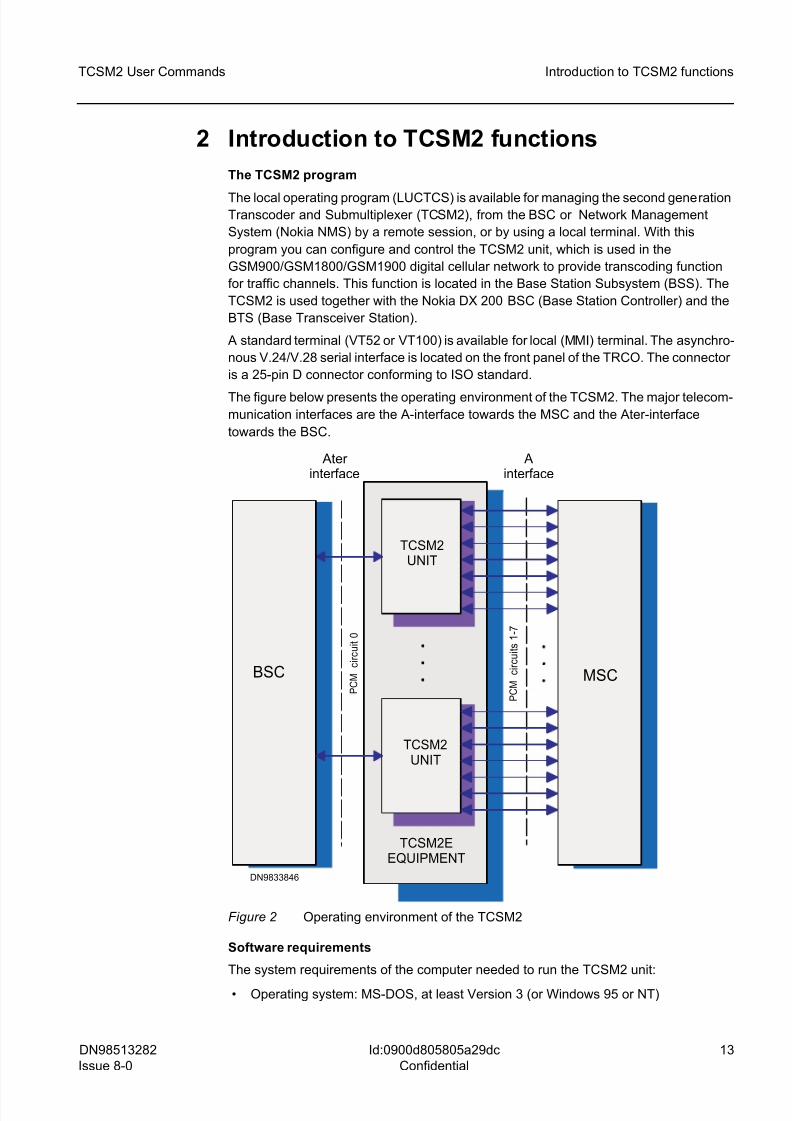
The figure below presents the operating environment of the TCSM2. The major telecom-
munication interfaces are the A-interface towards the MSC and the Ater-interface
towards the BSC.
Figure 2 Operating environment of the TCSM2
Software requirements
The system requirements of the computer needed to run the TCSM2 unit:
• Operating system: MS-DOS, at least Version 3 (or Windows 95 or NT)
DN9833846
P C M
c i r c u
i t 0
P C M
c i r c u
i t s 1
- 7
TCSM2EEQUIPMENT
MSC
TCSM2UNIT
Ater
interface A
interface
TCSM2UNIT
BSC
8/10/2019 TCSM COMMAND.pdf
http://slidepdf.com/reader/full/tcsm-commandpdf 14/125
14 DN98513282
Issue 8-0
TCSM2 User Commands
Id:0900d805805a29dc
Confidential
Introduction to TCSM2 functions
• Microsoft windows 3.1, 3.11, or later (optional)
• Terminal software with Kermit protocol
Hardware requirements
The system requirements of the computer needed to run the TCSM2 unit:
• IBM PC-compatible computer (at least 80286)
• Cable PC - TCSM, connections shown in Cable connections (RS-232C)
• Mouse, track ball or equivalent pointing device (optional)
• Serial port for communication to the TCSM2 unit
• 3.5 in. floppy drive for the installation diskette
Display unit types
The software supports the following display unit types:
• VT52
• VT100 (default terminal)
Operation in error situations
Any message unknown to the local user interface will be discarded. The program checks
the semantics of the commands and the correctness of the parameters. If these are
incorrect, an error message appears on the screen. If the command, for some reason,
is unexecutable, an error message will also appear on the screen.
Line parameters and terminal settings
The normal settings for the local terminal line are:
• bit rate 9600 bit/s or 19200 bit/s
• 7 data bits
• even parity
• 1 stop bit
The terminal line does not, however, check the parity at reception, and 1 stop bit is suf-
ficient.
For optimum results, note also the following:
• no automatic line feed (auto wrap off)
• tabulation at 16 character intervals
• xon/xoff protocol
• no local echoing (local echo off)
• sending of break character allowed (break on)
8/10/2019 TCSM COMMAND.pdf
http://slidepdf.com/reader/full/tcsm-commandpdf 15/125
DN98513282
Issue 8-0
15
TCSM2 User Commands Getting started
Id:0900d805805a29df
Confidential
3 Getting startedConnect your terminal (PC or VDU) to the front panel connector of the TRCO plug-in
unit. The connector is a 25-pin D connector. The cable used depends on your terminal.
Cable connections (RS-232C) shows the pin configurations for the connection cables:
PC - TCSM and VDU - TCSM.
g Make sure that all the rack doors are closed during normal operation.
3.1 Session priority
A local session has a higher priority than a remote session.
• If you try to start a remote session while a local session is under way, it will not
succeed and you will get a message stating that a local session is under way.
• If you start a local session while a remote session is under way, the remote session
will be discontinued and you will get a message stating this. • If you start a remote session while another remote session is under way, the earlier
session will remain and you will get a message stating this.
You start a local session by giving a session start request by pressing ENTER. For a
remote session, give a session start command from the BSC. Then you are prompted
for user identification and password.
3.2 Starting and ending a local session
This section assumes that the terminal is connected to an operational TCSM2 unit.
To start a local session:
1. Switch on your computer terminal and set the <CAPS LOCK> on for commands.
2. Start your terminal session.
3. Type your user name: USERNAME> USER or USERNAME> EXPERT
4. Type your password: PASSWORD> SYSTEM
5. After the first logging in, change the password.
6. When the logging in procedure is complete, the terminal is ready for further
commands and the display shows the LOCAL:LUC> command prompt or the
TCSM_XXX:LUC> command prompt.
g In a local session, the command prompt is LOCAL:LUC> when no connection
to the BSC is established. Once a connection is established to the BSC, the
command prompt changes to TCSM_XXX:LUC>. ̀ XXX' can be for example 032.The number is the index number of the transcoder unit concerned. In a remote
session, the prompt is always TCSM_XXX:LUC>. In this manual, the
TCSM_XXX:LUC> prompt is always shown.
When you type your user name and password correctly, the notice LOCAL
USER LOGGED IN is obtained. The program checks the syntax and semantics of the
commands entered and, after execution of the commands, the output is displayed on
the screen.
To end a local session, give the main menu command X (EXIT):
TCSM_XXX:LUC> X
Then the notice LOCAL USER LOGGED IN is removed and the program waits for startrequests.
8/10/2019 TCSM COMMAND.pdf
http://slidepdf.com/reader/full/tcsm-commandpdf 16/125
16 DN98513282
Issue 8-0
TCSM2 User Commands
Id:0900d805805a29df
Confidential
Getting started
3.3 Starting and ending a remote session through the BSC
A remote session to the TCSM2 is available through the same MML session that is used
to manage the BSC itself. For information on the MML commands, see the BSC docu-
mentation.
To start a remote session:
1. Start your MML session
2. Type your user name: USERNAME>
3. Type your password: PASSWORD>
4. When the logging in procedure is complete, the terminal is ready for further
commands and the display shows the TCSM_XXX:LUC> command prompt.
5. Type the command to establish the remote session to TCSM2:
ZDDT:TCSM,x;
(x = index for the TCSM2 concerned)
To end a remote session, give the main menu command X (EXIT):
TCSM_XXX:LUC> X
3.4 Menu commands
Available commands
The user interface is menu based. From the main menu you can go to various sub-
menus and choose the required command by typing it. The sub-menus are grouped
according to their usage.
Main menu commands
The main menu commands are shown below. They are described in more detail in
section TCSM2 commands.
LOCAL USER COMMUNICATION COMMANDS OF TCSM2
? ..... MENU / HELP
A ..... ALARM HANDLING COMMANDS
C ..... DIAGNOSTICS COMMANDS
L ..... SYNCHRONIZATION COMMANDS
G ..... GENERAL CONFIGURATION COMMANDS
R ..... TRANSCODER CONFIGURATION COMMANDS
E ..... EXCHANGE TERMINAL SUPERVISION COMMANDS
U ..... UNIT RESTART AND STATE HANDLING COMMANDS
I ..... STATISTICS COMMANDS
D ..... MEMORY AND I/O HANDLING COMMANDS
O ..... OPERATING SYSTEM COMMANDS
S ..... SYSTEM MONITORING COMMANDS
T ..... SET AND DISPLAY TERMINAL
X ..... EXIT
TCSM_XXX:LUC>
Common commands
Each command group has a sub-menu opened by a one-letter command. All the menushave following two commands in common:
8/10/2019 TCSM COMMAND.pdf
http://slidepdf.com/reader/full/tcsm-commandpdf 17/125
DN98513282
Issue 8-0
17
TCSM2 User Commands Getting started
Id:0900d805805a29df
Confidential
? types the menu
Z returns to the main menu
Help function
When you type ? and one of the command letters, you get a description of its parameters
and syntax. For example, when you are in the menu SYNCHRONIZATION
COMMANDS and give the command ?P, the following message is displayed:
CHANGE SYNCHRONIZATION INPUT PRIORITY
P:SIGNAL INDEX,PRIORITY;
SIGNAL INDEX BYTE 1..8
1 = PCM-1
2 = PCM-2
3 = PCM-3
4 = PCM-4 5 = PCM-5
6 = PCM-6
7 = PCM-7
8 = EXTERNAL SIGNAL
PRIORITY BYTE 1..15
Line editor
The line editor is available at all levels. It provides the following commands:
BACKSPACE Deletes the previous character and the cursor (as well as the whole
line) moves one position left.
ESC Interrupts the display of commands when the local session is being
used.
CTRL-C Interrupts the display of commands when the remote session through
the BSC is being used.
In a local session, there is a command history. The arrow keys (UP and DOWN) can be
used to view the command history. The LEFT and RIGHT arrow keys move the cursor
on the line.
g Only CAPITAL LETTERS are acceptable in commands.
8/10/2019 TCSM COMMAND.pdf
http://slidepdf.com/reader/full/tcsm-commandpdf 18/125
18 DN98513282
Issue 8-0
TCSM2 User Commands
Id:0900d805805a29e2
Confidential
TCSM2 commands
4 TCSM2 commands
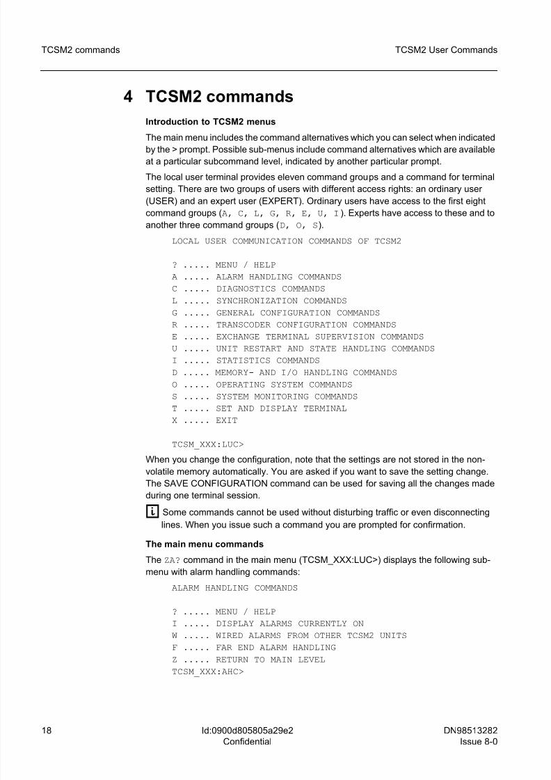
Introduction to TCSM2 menus
The main menu includes the command alternatives which you can select when indicatedby the > prompt. Possible sub-menus include command alternatives which are available
at a particular subcommand level, indicated by another particular prompt.
The local user terminal provides eleven command groups and a command for terminal
setting. There are two groups of users with different access rights: an ordinary user
(USER) and an expert user (EXPERT). Ordinary users have access to the first eight
command groups (A, C, L, G, R, E, U, I). Experts have access to these and to
another three command groups (D, O, S).
LOCAL USER COMMUNICATION COMMANDS OF TCSM2
? ..... MENU / HELP
A ..... ALARM HANDLING COMMANDS
C ..... DIAGNOSTICS COMMANDS
L ..... SYNCHRONIZATION COMMANDS
G ..... GENERAL CONFIGURATION COMMANDS
R ..... TRANSCODER CONFIGURATION COMMANDS
E ..... EXCHANGE TERMINAL SUPERVISION COMMANDS
U ..... UNIT RESTART AND STATE HANDLING COMMANDS
I ..... STATISTICS COMMANDS
D ..... MEMORY- AND I/O HANDLING COMMANDS
O ..... OPERATING SYSTEM COMMANDS
S ..... SYSTEM MONITORING COMMANDS
T ..... SET AND DISPLAY TERMINALX ..... EXIT
TCSM_XXX:LUC>
When you change the configuration, note that the settings are not stored in the non-
volatile memory automatically. You are asked if you want to save the setting change.
The SAVE CONFIGURATION command can be used for saving all the changes made
during one terminal session.
g Some commands cannot be used without disturbing traffic or even disconnecting
lines. When you issue such a command you are prompted for confirmation.
The main menu commandsThe ZA? command in the main menu (TCSM_XXX:LUC>) displays the following sub-
menu with alarm handling commands:
ALARM HANDLING COMMANDS
? ..... MENU / HELP
I ..... DISPLAY ALARMS CURRENTLY ON
W ..... WIRED ALARMS FROM OTHER TCSM2 UNITS
F ..... FAR END ALARM HANDLING
Z ..... RETURN TO MAIN LEVEL
TCSM_XXX:AHC>
8/10/2019 TCSM COMMAND.pdf
http://slidepdf.com/reader/full/tcsm-commandpdf 19/125
DN98513282
Issue 8-0
19
TCSM2 User Commands TCSM2 commands
Id:0900d805805a29e2
Confidential
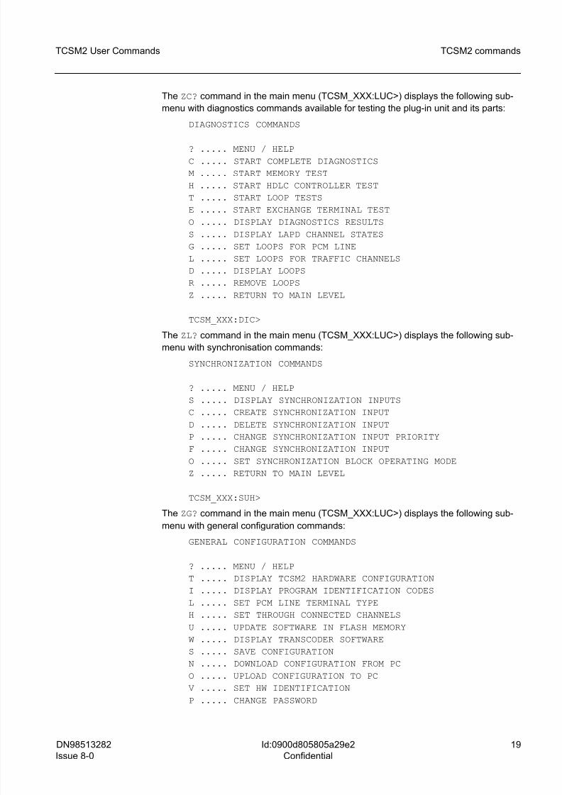
The ZC? command in the main menu (TCSM_XXX:LUC>) displays the following sub-
menu with diagnostics commands available for testing the plug-in unit and its parts:
DIAGNOSTICS COMMANDS
? ..... MENU / HELP
C ..... START COMPLETE DIAGNOSTICS
M ..... START MEMORY TEST
H ..... START HDLC CONTROLLER TEST
T ..... START LOOP TESTS
E ..... START EXCHANGE TERMINAL TEST
O ..... DISPLAY DIAGNOSTICS RESULTS
S ..... DISPLAY LAPD CHANNEL STATES
G ..... SET LOOPS FOR PCM LINE
L ..... SET LOOPS FOR TRAFFIC CHANNELS
D ..... DISPLAY LOOPS
R ..... REMOVE LOOPS
Z ..... RETURN TO MAIN LEVEL
TCSM_XXX:DIC>
The ZL? command in the main menu (TCSM_XXX:LUC>) displays the following sub-
menu with synchronisation commands:
SYNCHRONIZATION COMMANDS
? ..... MENU / HELP
S ..... DISPLAY SYNCHRONIZATION INPUTS
C ..... CREATE SYNCHRONIZATION INPUT
D ..... DELETE SYNCHRONIZATION INPUT
P ..... CHANGE SYNCHRONIZATION INPUT PRIORITY
F ..... CHANGE SYNCHRONIZATION INPUT
O ..... SET SYNCHRONIZATION BLOCK OPERATING MODE
Z ..... RETURN TO MAIN LEVEL
TCSM_XXX:SUH>
The ZG? command in the main menu (TCSM_XXX:LUC>) displays the following sub-
menu with general configuration commands:
GENERAL CONFIGURATION COMMANDS
? ..... MENU / HELP
T ..... DISPLAY TCSM2 HARDWARE CONFIGURATION
I ..... DISPLAY PROGRAM IDENTIFICATION CODES
L ..... SET PCM LINE TERMINAL TYPE
H ..... SET THROUGH CONNECTED CHANNELS
U ..... UPDATE SOFTWARE IN FLASH MEMORY
W ..... DISPLAY TRANSCODER SOFTWARE
S ..... SAVE CONFIGURATION
N ..... DOWNLOAD CONFIGURATION FROM PC
O ..... UPLOAD CONFIGURATION TO PC
V ..... SET HW IDENTIFICATION
P ..... CHANGE PASSWORD
8/10/2019 TCSM COMMAND.pdf
http://slidepdf.com/reader/full/tcsm-commandpdf 20/125
20 DN98513282
Issue 8-0
TCSM2 User Commands
Id:0900d805805a29e2
Confidential
TCSM2 commands
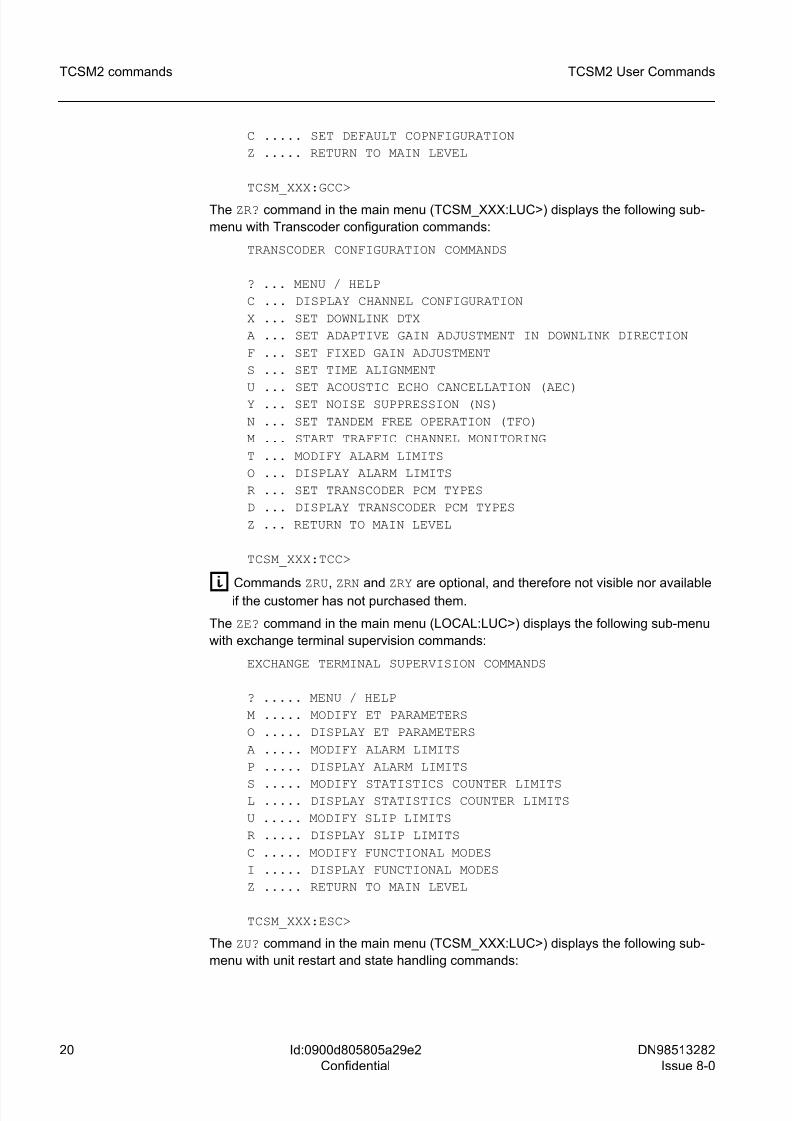
C ..... SET DEFAULT COPNFIGURATION
Z ..... RETURN TO MAIN LEVEL
TCSM_XXX:GCC>
The ZR? command in the main menu (TCSM_XXX:LUC>) displays the following sub-
menu with Transcoder configuration commands:
TRANSCODER CONFIGURATION COMMANDS
? ... MENU / HELP
C ... DISPLAY CHANNEL CONFIGURATION
X ... SET DOWNLINK DTX
A ... SET ADAPTIVE GAIN ADJUSTMENT IN DOWNLINK DIRECTION
F ... SET FIXED GAIN ADJUSTMENT
S ... SET TIME ALIGNMENT
U ... SET ACOUSTIC ECHO CANCELLATION (AEC)Y ... SET NOISE SUPPRESSION (NS)
N ... SET TANDEM FREE OPERATION (TFO)
M ... START TRAFFIC CHANNEL MONITORING
T ... MODIFY ALARM LIMITS
O ... DISPLAY ALARM LIMITS
R ... SET TRANSCODER PCM TYPES
D ... DISPLAY TRANSCODER PCM TYPES
Z ... RETURN TO MAIN LEVEL
TCSM_XXX:TCC>
g Commands ZRU, ZRN and ZRY are optional, and therefore not visible nor availableif the customer has not purchased them.
The ZE? command in the main menu (LOCAL:LUC>) displays the following sub-menu
with exchange terminal supervision commands:
EXCHANGE TERMINAL SUPERVISION COMMANDS
? ..... MENU / HELP
M ..... MODIFY ET PARAMETERS
O ..... DISPLAY ET PARAMETERS
A ..... MODIFY ALARM LIMITS
P ..... DISPLAY ALARM LIMITS
S ..... MODIFY STATISTICS COUNTER LIMITSL ..... DISPLAY STATISTICS COUNTER LIMITS
U ..... MODIFY SLIP LIMITS
R ..... DISPLAY SLIP LIMITS
C ..... MODIFY FUNCTIONAL MODES
I ..... DISPLAY FUNCTIONAL MODES
Z ..... RETURN TO MAIN LEVEL
TCSM_XXX:ESC>
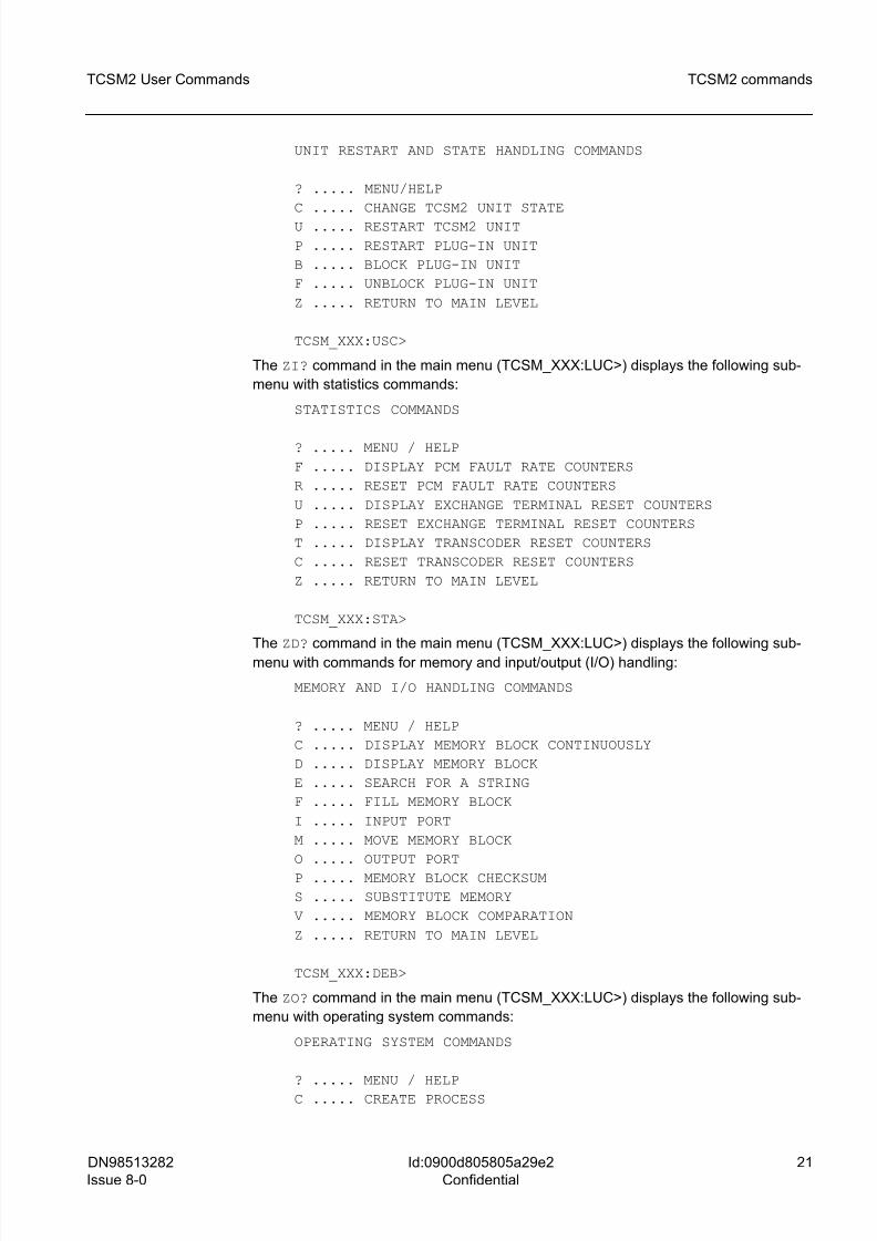
The ZU? command in the main menu (TCSM_XXX:LUC>) displays the following sub-
menu with unit restart and state handling commands:
8/10/2019 TCSM COMMAND.pdf
http://slidepdf.com/reader/full/tcsm-commandpdf 21/125
DN98513282
Issue 8-0
21
TCSM2 User Commands TCSM2 commands
Id:0900d805805a29e2
Confidential
UNIT RESTART AND STATE HANDLING COMMANDS
? ..... MENU/HELP
C ..... CHANGE TCSM2 UNIT STATE
U ..... RESTART TCSM2 UNIT
P ..... RESTART PLUG-IN UNIT
B ..... BLOCK PLUG-IN UNIT
F ..... UNBLOCK PLUG-IN UNIT
Z ..... RETURN TO MAIN LEVEL
TCSM_XXX:USC>
The ZI? command in the main menu (TCSM_XXX:LUC>) displays the following sub-
menu with statistics commands:
STATISTICS COMMANDS
? ..... MENU / HELP
F ..... DISPLAY PCM FAULT RATE COUNTERS
R ..... RESET PCM FAULT RATE COUNTERS
U ..... DISPLAY EXCHANGE TERMINAL RESET COUNTERS
P ..... RESET EXCHANGE TERMINAL RESET COUNTERS
T ..... DISPLAY TRANSCODER RESET COUNTERS
C ..... RESET TRANSCODER RESET COUNTERS
Z ..... RETURN TO MAIN LEVEL
TCSM_XXX:STA>
The ZD? command in the main menu (TCSM_XXX:LUC>) displays the following sub-
menu with commands for memory and input/output (I/O) handling:
MEMORY AND I/O HANDLING COMMANDS
? ..... MENU / HELP
C ..... DISPLAY MEMORY BLOCK CONTINUOUSLY
D ..... DISPLAY MEMORY BLOCK
E ..... SEARCH FOR A STRING
F ..... FILL MEMORY BLOCK
I ..... INPUT PORT
M ..... MOVE MEMORY BLOCK
O ..... OUTPUT PORT
P ..... MEMORY BLOCK CHECKSUM
S ..... SUBSTITUTE MEMORY
V ..... MEMORY BLOCK COMPARATION
Z ..... RETURN TO MAIN LEVEL
TCSM_XXX:DEB>
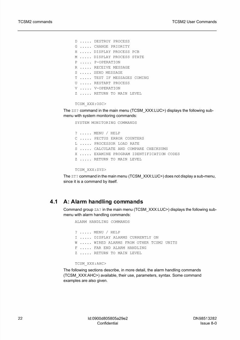
The ZO? command in the main menu (TCSM_XXX:LUC>) displays the following sub-
menu with operating system commands:
OPERATING SYSTEM COMMANDS
? ..... MENU / HELPC ..... CREATE PROCESS
8/10/2019 TCSM COMMAND.pdf
http://slidepdf.com/reader/full/tcsm-commandpdf 22/125
22 DN98513282
Issue 8-0
TCSM2 User Commands
Id:0900d805805a29e2
Confidential
TCSM2 commands
D ..... DESTROY PROCESS
G ..... CHANGE PRIORITY
H ..... DISPLAY PROCESS PCB
M ..... DISPLAY PROCESS STATE
P ..... P-OPERATION
R ..... RECEIVE MESSAGE
S ..... SEND MESSAGE
T ..... TEST IF MESSAGES COMING
U ..... RESTART PROCESS
V ..... V-OPERATION
Z ..... RETURN TO MAIN LEVEL
TCSM_XXX:OSC>
The ZS? command in the main menu (TCSM_XXX:LUC>) displays the following sub-
menu with system monitoring commands:
SYSTEM MONITORING COMMANDS
? ..... MENU / HELP
C ..... PECTUS ERROR COUNTERS
L ..... PROCESSOR LOAD RATE
S ..... CALCULATE AND COMPARE CHECKSUMS
X ..... EXAMINE PROGRAM IDENTIFICATION CODES
Z ..... RETURN TO MAIN LEVEL
TCSM_XXX:SYS>
The ZT? command in the main menu (TCSM_XXX:LUC>) does not display a sub-menu,
since it is a command by itself.
4.1 A: Alarm handling commands
Command group ZA? in the main menu (TCSM_XXX:LUC>) displays the following sub-
menu with alarm handling commands:
ALARM HANDLING COMMANDS
? ..... MENU / HELP
I ..... DISPLAY ALARMS CURRENTLY ONW ..... WIRED ALARMS FROM OTHER TCSM2 UNITS
F ..... FAR END ALARM HANDLING
Z ..... RETURN TO MAIN LEVEL
TCSM_XXX:AHC>
The following sections describe, in more detail, the alarm handling commands
(TCSM_XXX:AHC>) available, their use, parameters, syntax. Some command
examples are also given.
8/10/2019 TCSM COMMAND.pdf
http://slidepdf.com/reader/full/tcsm-commandpdf 23/125
DN98513282
Issue 8-0
23
TCSM2 User Commands TCSM2 commands
Id:0900d805805a29e2
Confidential
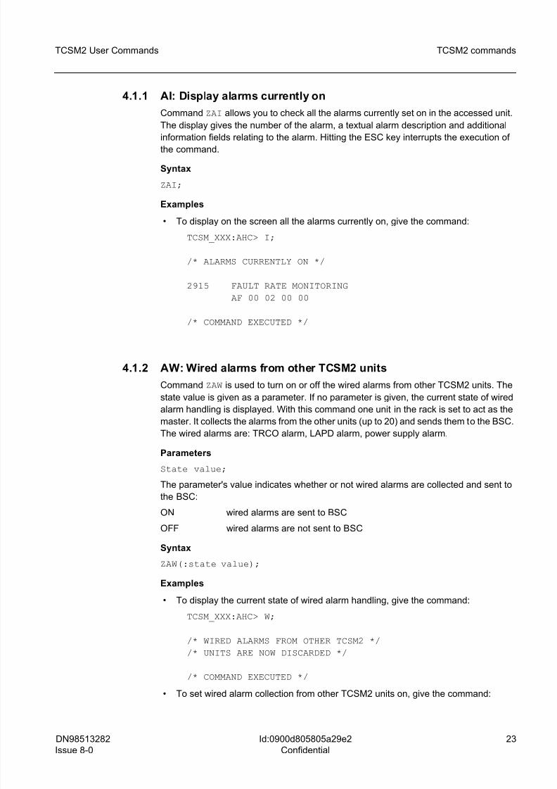
4.1.1 AI: Display alarms currently on
Command ZAI allows you to check all the alarms currently set on in the accessed unit.
The display gives the number of the alarm, a textual alarm description and additional
information fields relating to the alarm. Hitting the ESC key interrupts the execution ofthe command.
Syntax
ZAI;
Examples
• To display on the screen all the alarms currently on, give the command:
TCSM_XXX:AHC> I;
/* ALARMS CURRENTLY ON */
2915 FAULT RATE MONITORING
AF 00 02 00 00
/* COMMAND EXECUTED */
4.1.2 AW: Wired alarms from other TCSM2 units
Command ZAW is used to turn on or off the wired alarms from other TCSM2 units. The
state value is given as a parameter. If no parameter is given, the current state of wired
alarm handling is displayed. With this command one unit in the rack is set to act as the
master. It collects the alarms from the other units (up to 20) and sends them to the BSC.
The wired alarms are: TRCO alarm, LAPD alarm, power supply alarm.
Parameters
State value;
The parameter's value indicates whether or not wired alarms are collected and sent to
the BSC:
ON wired alarms are sent to BSC
OFF wired alarms are not sent to BSC
Syntax
ZAW(:state value);
Examples
• To display the current state of wired alarm handling, give the command:
TCSM_XXX:AHC> W;
/* WIRED ALARMS FROM OTHER TCSM2 */
/* UNITS ARE NOW DISCARDED */
/* COMMAND EXECUTED */
• To set wired alarm collection from other TCSM2 units on, give the command:
8/10/2019 TCSM COMMAND.pdf
http://slidepdf.com/reader/full/tcsm-commandpdf 24/125
24 DN98513282
Issue 8-0
TCSM2 User Commands
Id:0900d805805a29e2
Confidential
TCSM2 commands
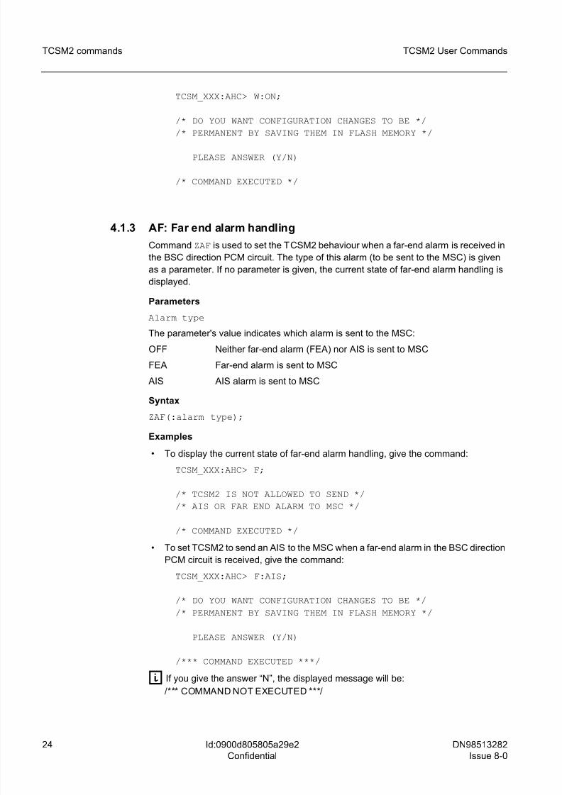
TCSM_XXX:AHC> W:ON;
/* DO YOU WANT CONFIGURATION CHANGES TO BE */
/* PERMANENT BY SAVING THEM IN FLASH MEMORY */
PLEASE ANSWER (Y/N)
/* COMMAND EXECUTED */
4.1.3 AF: Far end alarm handling
Command ZAF is used to set the TCSM2 behaviour when a far-end alarm is received in
the BSC direction PCM circuit. The type of this alarm (to be sent to the MSC) is given
as a parameter. If no parameter is given, the current state of far-end alarm handling is
displayed.
Parameters
Alarm type
The parameter's value indicates which alarm is sent to the MSC:
OFF Neither far-end alarm (FEA) nor AIS is sent to MSC
FEA Far-end alarm is sent to MSC
AIS AIS alarm is sent to MSC
Syntax
ZAF(:alarm type);
Examples
• To display the current state of far-end alarm handling, give the command:
TCSM_XXX:AHC> F;
/* TCSM2 IS NOT ALLOWED TO SEND */
/* AIS OR FAR END ALARM TO MSC */
/* COMMAND EXECUTED */
• To set TCSM2 to send an AIS to the MSC when a far-end alarm in the BSC direction
PCM circuit is received, give the command:
TCSM_XXX:AHC> F:AIS;
/* DO YOU WANT CONFIGURATION CHANGES TO BE */
/* PERMANENT BY SAVING THEM IN FLASH MEMORY */
PLEASE ANSWER (Y/N)
/*** COMMAND EXECUTED ***/
g If you give the answer “N”, the displayed message will be:
/*** COMMAND NOT EXECUTED ***/
8/10/2019 TCSM COMMAND.pdf
http://slidepdf.com/reader/full/tcsm-commandpdf 25/125
DN98513282
Issue 8-0
25
TCSM2 User Commands TCSM2 commands
Id:0900d805805a29e2
Confidential
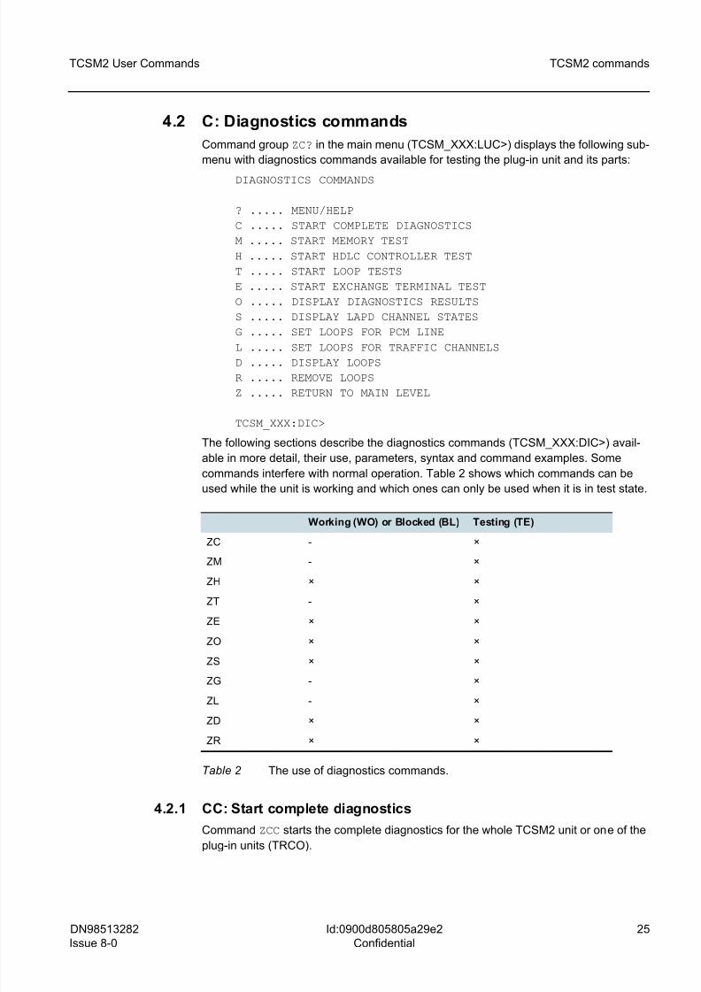
4.2 C: Diagnostics commands
Command group ZC? in the main menu (TCSM_XXX:LUC>) displays the following sub-
menu with diagnostics commands available for testing the plug-in unit and its parts:
DIAGNOSTICS COMMANDS
? ..... MENU/HELP
C ..... START COMPLETE DIAGNOSTICS
M ..... START MEMORY TEST
H ..... START HDLC CONTROLLER TEST
T ..... START LOOP TESTS
E ..... START EXCHANGE TERMINAL TEST
O ..... DISPLAY DIAGNOSTICS RESULTS
S ..... DISPLAY LAPD CHANNEL STATES
G ..... SET LOOPS FOR PCM LINE
L ..... SET LOOPS FOR TRAFFIC CHANNELSD ..... DISPLAY LOOPS
R ..... REMOVE LOOPS
Z ..... RETURN TO MAIN LEVEL
TCSM_XXX:DIC>
The following sections describe the diagnostics commands (TCSM_XXX:DIC>) avail-
able in more detail, their use, parameters, syntax and command examples. Some
commands interfere with normal operation. Table 2 shows which commands can be
used while the unit is working and which ones can only be used when it is in test state.
4.2.1 CC: Start complete diagnostics
Command ZCC starts the complete diagnostics for the whole TCSM2 unit or one of the
plug-in units (TRCO).
Working (WO) or Blocked (BL) Testing (TE)
ZC - ×
ZM - ×
ZH × ×
ZT - ×
ZE × ×
ZO × ×
ZS × ×
ZG - ×
ZL - ×
ZD × ×
ZR × ×
Table 2 The use of diagnostics commands.
8/10/2019 TCSM COMMAND.pdf
http://slidepdf.com/reader/full/tcsm-commandpdf 26/125
26 DN98513282
Issue 8-0
TCSM2 User Commands
Id:0900d805805a29e2
Confidential
TCSM2 commands
Parameters
Plug-in unit identifier (TRCO plug-in unit or TOTAL for the whole TCSM unit).
Syntax
ZCC: plug-in unit identifier;
Examples
• To start the diagnostics for the TCSM unit, give the command:
TCSM_XXX:DIC> C:TOTAL;
/* ALL CALLS WILL BE CANCELLED DUE */
/* TO GIVEN COMMAND */
PLEASE CONFIRM (Y/N)
EXECUTING COMPLETE DIAGNOSTICS ...
(at this point the unit restarts)
/* COMMAND EXECUTED */
• To start the diagnostics for the TRCO plug-in unit, give the command:
TCSM_XXX:DIC> C:TRCO;
/* ALL CALLS WILL BE CANCELLED DUE */
/* TO GIVEN COMMAND */
PLEASE CONFIRM (Y/N)
EXECUTING COMPLETE DIAGNOSTICS ...
(at this point the unit restarts)
/* COMMAND EXECUTED */
Functional notes
The diagnostics procedure for the TRCO plug-in unit includes a memory test (RAM,
FLASH), a clock test, a loop test for the HDLC controller and a watchdog test. The diag-
nostics procedure for the whole TCSM unit also includes a loop test 1 and ET diagnos-
tics. In this test, each transcoder sends data towards the BSC and MSC and the
transmitted data is compared to the data looped back by the ET2A/ET2E plug-in units.The test lasts 5 to 7 minutes. After the restart the diagnostics results are displayed auto-
matically on the local terminal. Later, the results can be displayed with a command
(ZCO;).
Execution errors
/*** CANNOT PERFORM TEST ***/
/*** LAST DIAGNOSTICS NOT READY ***/
8/10/2019 TCSM COMMAND.pdf
http://slidepdf.com/reader/full/tcsm-commandpdf 27/125
DN98513282
Issue 8-0
27
TCSM2 User Commands TCSM2 commands
Id:0900d805805a29e2
Confidential
4.2.2 CM: Start memory test
Command ZCM starts the diagnostics for the RAM and FLASH memory circuits of the
TRCO. The RAM test lasts 1.5 minutes.
Parameters
Memory type, which may be RAM or FLASH.
If you give no parameter, both types will be tested.
Syntax
ZCM(:memory type);
Examples
• To test the RAM memory of the TRCO plug-in unit, give the command:
TCSM_XXX:DIC> M:RAM;
/* UNIT MAY NOT WORK NORMALLY AFTER */
/* COMMAND HAS BEEN GIVEN */
PLEASE CONFIRM EXECUTION (Y/N)
EXECUTING MEMORY TEST ...
/* COMMAND EXECUTED */
• To test both memory types (RAM and FLASH) of the TRCO plug-in unit, give the
command:
TCSM_XXX:DIC> M;
/* EXECUTING MEMORY TEST */
/* COMMAND EXECUTED */
Execution errors
/*** CANNOT PERFORM TEST ***/
/*** LAST DIAGNOSTICS NOT READY ***/
/*** INCORRECT UNIT STATE FOR TEST ***/
4.2.3 CH: Start HDLC controller test
Command ZCH starts the HDLC controller test for the LAPD channels.
Parameters
Identification of the LAPD channel, which is a decimal number between 0 and 4.
0 LAPD channel for the BSC
1 - 4 LAPD channels for the ET2E/ET2A plug-in unit
If you give no parameter, all channels will be tested.
8/10/2019 TCSM COMMAND.pdf
http://slidepdf.com/reader/full/tcsm-commandpdf 28/125
28 DN98513282
Issue 8-0
TCSM2 User Commands
Id:0900d805805a29e2
Confidential
TCSM2 commands
Syntax
ZCH(:Identification for the LAPD channel);
Examples
• To start the HDLC controller test for the BSC, give the command:
TCSM_XXX:DIC> H:0;
/* UNIT MAY NOT WORK NORMALLY AFTER */
/* COMMAND HAS BEEN GIVEN */
PLEASE CONFIRM EXECUTION (Y/N)
/* COMMAND EXECUTED */
• To start the HDLC controller test for all channels (BSC and ETs), give the command:
TCSM_XXX:DIC> H;
/* UNIT MAY NOT WORK NORMALLY AFTER */
/* COMMAND HAS BEEN GIVEN */
PLEASE CONFIRM EXECUTION (Y/N)
/* COMMAND EXECUTED */
Execution errors
/*** CANNOT PERFORM TEST ***/
/*** LAST DIAGNOSTICS NOT READY ***/
4.2.4 CT: Start loop tests
Command ZCT starts two different loop tests. Test 0 sends back the received data from
the MSC after encoding and decoding. Looping is defined by the parameter. Test 1
starts the loop testing for certain transcoders, which send data towards the MSC and
BSC interfaces and compare the received data with the transmitted data. The
ET2E/ET2A plug-in units loop the data back automatically.
The command may apply to all the PCM channels of one MSC direction or all the
channels of the whole unit.
Parameters
PCM circuit index / ALL channels selected, loop test, loop-back,
control time / test set OFF;
PCM circuit index:
Decimal number 1 - 7, the number of the tested PCM circuit towards MSC direction.
ALL channels selected:
Select the parameter instead of the PCM circuit index and timeslot if you want to perform
a loop test on all channels of the unit; type ALL.
Loop test:
8/10/2019 TCSM COMMAND.pdf
http://slidepdf.com/reader/full/tcsm-commandpdf 29/125
DN98513282
Issue 8-0
29
TCSM2 User Commands TCSM2 commands
Id:0900d805805a29e2
Confidential
Defines one of the available loop tests 0 or 1, decimal number 0 or 1.
Loop-back:
Specifies where the actual loop-back takes place in loop test 0 (ET or NO).
ET Loop-back to ET2A/ET2E in BSC direction
NO No loop-back
This parameter is unnecessary for loop test 1.
Control time:
PERIOD = control time format: HH-MM
Specifies the duration of the loop test selected. The shortest allowed test period is 00-
01 and the longest period is 18-00 (18 hours). The default is 30 seconds.
Test set OFF:
This can be the only parameter for the command, and then the active loop test will be
stopped.
Syntax
ZCT: (PCM circuit index) / ALL channels selected: TEST = <loop
test>, LOOP = <loop-back>, PERIOD = <control time> );
ZCT: OFF; the loop test set on discontinued
Examples
• To start loop test 1 for a channel on PCM circuit 3, give the command:
TCSM_XXX:DIC> T:3:TEST=1;
/* UNIT MAY NOT WORK NORMALLY AFTER */
/* COMMAND HAS BEEN GIVEN */
PLEASE CONFIRM EXECUTION (Y/N)
/* COMMAND EXECUTED */
g The test lasts for 30 seconds (default setting).
• To start loop test 1 on all channels on PCM circuit 4 for 18 hours, give the command:
TCSM_XXX:DIC> T:4:TEST=1,PERIOD=18-00;
/* UNIT MAY NOT WORK NORMALLY AFTER *//* COMMAND HAS BEEN GIVEN */
PLEASE CONFIRM EXECUTION (Y/N)
/* COMMAND EXECUTED */
• To start loop test 1 on all channels of the unit, give the command:
TCSM_XXX:DIC> T:ALL:TEST=1;
/* UNIT MAY NOT WORK NORMALLY AFTER */
/* COMMAND HAS BEEN GIVEN */
8/10/2019 TCSM COMMAND.pdf
http://slidepdf.com/reader/full/tcsm-commandpdf 30/125
30 DN98513282
Issue 8-0
TCSM2 User Commands
Id:0900d805805a29e2
Confidential
TCSM2 commands
PLEASE CONFIRM EXECUTION (Y/N)
/* COMMAND EXECUTED */
• To stop the loop test currently set on, give the command:TCSM_XXX:DIC> T:OFF;
/* COMMAND EXECUTED */
• To start loop test 0 on all channels of the whole TCSM2 unit for one hour, and set
the actual loop-back at the ET2A/ET2E unit, give the command:
TCSM_XXX:DIC> T:ALL:TEST=0,LOOP=ET,PERIOD=01-00;
/* UNIT MAY NOT WORK NORMALLY AFTER */
/* COMMAND HAS BEEN GIVEN */
PLEASE CONFIRM EXECUTION (Y/N)
/* COMMAND EXECUTED */
Additional information
Note that the whole BSC direction PCM circuit is looped.
Only one loop test at a time can be set on. An error message appears if you try to start
another one.
Note also that when you start the command, all current calls on channels being tested
will be discontinued. You are warned and prompted for confirmation.
Execution errors
/*** CANNOT PERFORM TEST ***/
/*** LAST DIAGNOSTICS NOT READY ***/
4.2.5 CE: Start Exchange Terminal test
Command ZCE starts the exchange terminal (ET) test.
Parameters
ET plug-in unit identifier;
0 - 3 number of the plug-in unit to be tested
ALL all the plug-in units will be tested
Syntax
ZCE: ET plug-in unit identifier;
Examples
• To start the test on all ET plug-in units, give the command:
TCSM_XXX:DIC> E:ALL;
/* COMMAND EXECUTED */
8/10/2019 TCSM COMMAND.pdf
http://slidepdf.com/reader/full/tcsm-commandpdf 31/125
DN98513282
Issue 8-0
31
TCSM2 User Commands TCSM2 commands
Id:0900d805805a29e2
Confidential
• To start the test on ET plug-in units 0, give the command:
TCSM_XXX:DIC> E:0;
/* COMMAND EXECUTED */
Additional information
Only one exchange terminal test can be ongoing at any one time. If you try to initiate a
new test, while the previous one is still ongoing, you will receive an error message.
Execution errors
/*** CANNOT PERFORM TEST ***/
/*** LAST DIAGNOSTICS NOT READY ***/
/*** INCORRECT UNIT STATE FOR TEST ***/
/*** NO EQUIPMENT ***/
/*** MESSAGE TIMEOUT ***/
4.2.6 CO: Display diagnostics results
Command ZCO displays the results of the latest diagnostics test.
Syntax
ZCO;
Examples
• To display the results of the latest test (the memory test) give the command:
TCSM_XXX:DIC> O;
/* DIAGNOSTICS RESULTS */
RAM TEST OK
FLASH TEST OK
/* COMMAND EXECUTED */
• To display the results of the latest test (the loop test of the HDLC controllers of
channel 0), give the command:
TCSM_XXX:DIC> O;
/* DIAGNOSTICS RESULTS */
HDLC CONTROLLER TEST
FOR LAPD CHANNEL 0 1 2 3 4
OK - - - -
/* COMMAND EXECUTED */
8/10/2019 TCSM COMMAND.pdf
http://slidepdf.com/reader/full/tcsm-commandpdf 32/125
32 DN98513282
Issue 8-0
TCSM2 User Commands
Id:0900d805805a29e2
Confidential
TCSM2 commands
• To display the results of the latest test (the ET memory test of ET 0) give the
command:
TCSM_XXX:DIC> E:0;
/* DIAGNOSTICS RESULTS */
ET MEMORY TEST
FOR UNITS 0 1 2 3
OK NOT TESTED - -
• To display the results of the latest test, which is loop test 1 for all channels of the
unit, give the command:
TCSM_XXX:DIC> ZCO
/* DIAGNOSTICS RESULTS */
FAILED TIME SLOTS IN MSC DIRECTION IN LOOP TEST-1
PCM-3 : 2 4 6 8 10 12 14 16 18 20 22 24 26 28 30
FAILED TIME SLOTS IN BSC DIRECTION IN LOOP TEST-1
PCM-3 : 2 4 6 8 10 12 14 16 18 20 22 24 26 28 30
/* COMMAND EXECUTED */
• Display the results of the latest test, which is the complete diagnostics of the whole
TCSM2 unit.
TCSM_XXX:DIC> O;
/* DIAGNOSTICS RESULTS */
RAM TEST OK
FLASH TEST OK
WATCHDOG TEST OK
CLOCK TEST OK
HDLC CONTROLLER TEST
FOR LAPD CHANNEL 0 1 2 3 4
OK OK OK OK OK
LOOP TEST-1 OK
ET MEMORY TEST
FOR UNITS 0 1 2 3
OK OK OK OK
Diagnostics results
OK Test passed
FAILURE A fault
NOT TESTED The unit was not tested
8/10/2019 TCSM COMMAND.pdf
http://slidepdf.com/reader/full/tcsm-commandpdf 33/125
DN98513282
Issue 8-0
33
TCSM2 User Commands TCSM2 commands
Id:0900d805805a29e2
Confidential
• This channel was not tested, or this unit is not included in the con-
figuration
Execution errors
/*** NO DIAGNOSTICS RESULTS ***/
4.2.7 CS: Display LAPD channel states
Command ZCS displays the channel states of LAPD channels.
Syntax
ZCS;
Example
Display the LAPD channel states.
TCSM_XXX:DIC> S;
/* LAPD CHANNEL STATES */
LAPD CHANNEL TO
BSC : CONNECTION EXISTS
ET2A-0 : CONNECTION EXISTS
ET2A-1 : CONNECTION EXISTS
ET2A-2 : NO CONNECTION
ET2A-3 : NO CONNECTION
/* COMMAND EXECUTED */
g The state may be NO CONNECTION or CONNECTION EXISTS.
4.2.8 CG: Set loops for PCM circuit
Command ZCG sets loops for a PCM circuit at the T1/E1 interface, either in the BSC or
MSC direction.
ParametersPCM circuit index, timeslot, control time
PCM circuit index:
The number of the PCM circuit to be set on loop; decimal number 0 - 7.
0 PCM circuit in BSC direction
1–7 one of the PCM circuits in MSC direction
Timeslot:
Timeslot 1 - 24 (ANSI) 1...31 (ETSI)
g Timeslot can only be given in the ANSI (TCSM2A) application.
Control time:
8/10/2019 TCSM COMMAND.pdf
http://slidepdf.com/reader/full/tcsm-commandpdf 34/125
34 DN98513282
Issue 8-0
TCSM2 User Commands
Id:0900d805805a29e2
Confidential
TCSM2 commands
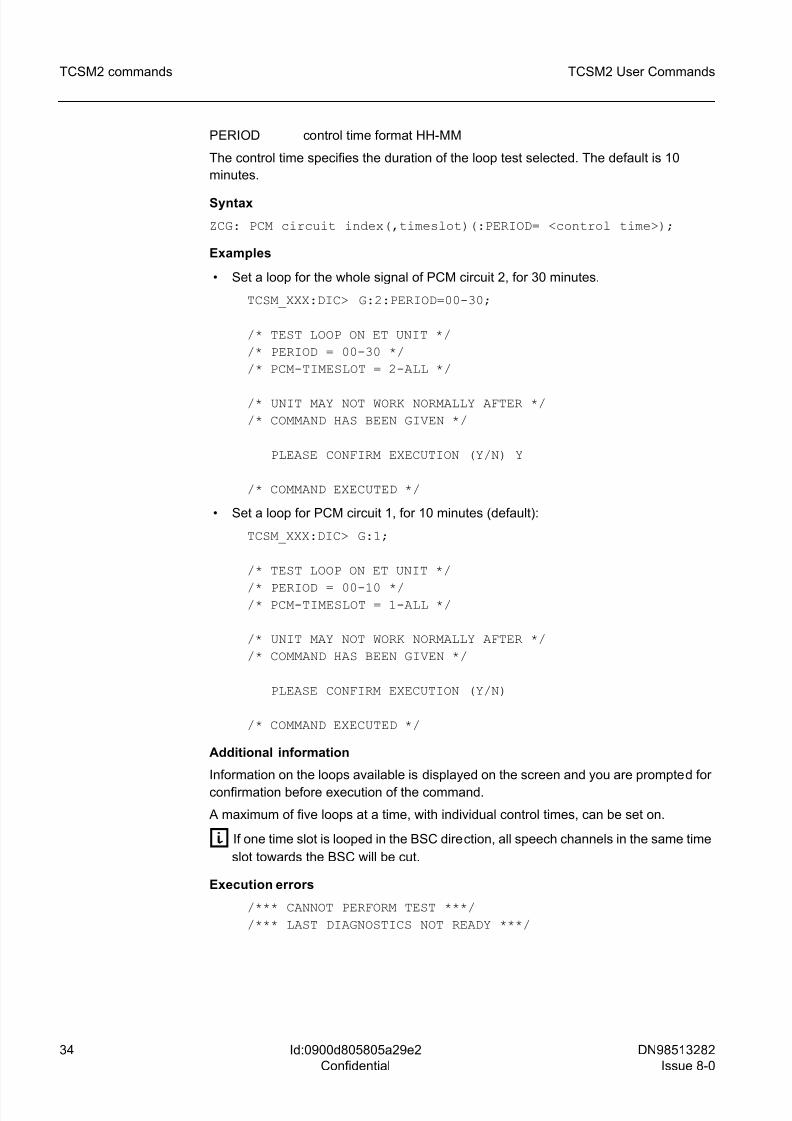
PERIOD control time format HH-MM
The control time specifies the duration of the loop test selected. The default is 10
minutes.
Syntax
ZCG: PCM circuit index(,timeslot)(:PERIOD= <control time>);
Examples
• Set a loop for the whole signal of PCM circuit 2, for 30 minutes.
TCSM_XXX:DIC> G:2:PERIOD=00-30;
/* TEST LOOP ON ET UNIT */
/* PERIOD = 00-30 */
/* PCM-TIMESLOT = 2-ALL */
/* UNIT MAY NOT WORK NORMALLY AFTER */
/* COMMAND HAS BEEN GIVEN */
PLEASE CONFIRM EXECUTION (Y/N) Y
/* COMMAND EXECUTED */
• Set a loop for PCM circuit 1, for 10 minutes (default):
TCSM_XXX:DIC> G:1;
/* TEST LOOP ON ET UNIT */
/* PERIOD = 00-10 *//* PCM-TIMESLOT = 1-ALL */
/* UNIT MAY NOT WORK NORMALLY AFTER */
/* COMMAND HAS BEEN GIVEN */
PLEASE CONFIRM EXECUTION (Y/N)
/* COMMAND EXECUTED */
Additional information
Information on the loops available is displayed on the screen and you are prompted for
confirmation before execution of the command.
A maximum of five loops at a time, with individual control times, can be set on.
g If one time slot is looped in the BSC direction, all speech channels in the same time
slot towards the BSC will be cut.
Execution errors
/*** CANNOT PERFORM TEST ***/
/*** LAST DIAGNOSTICS NOT READY ***/
8/10/2019 TCSM COMMAND.pdf
http://slidepdf.com/reader/full/tcsm-commandpdf 35/125
DN98513282
Issue 8-0
35
TCSM2 User Commands TCSM2 commands
Id:0900d805805a29e2
Confidential
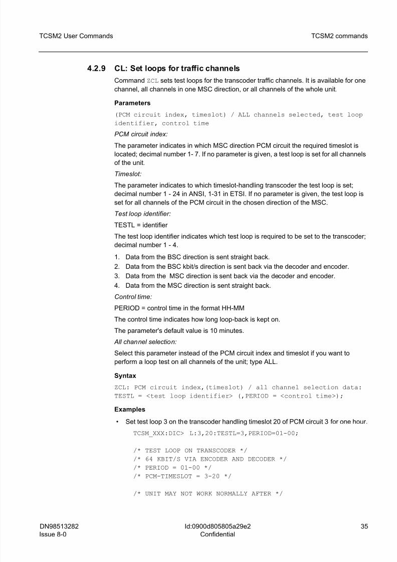
4.2.9 CL: Set loops for traffic channels
Command ZCL sets test loops for the transcoder traffic channels. It is available for one
channel, all channels in one MSC direction, or all channels of the whole unit.
Parameters
(PCM circuit index, timeslot) / ALL channels selected, test loop
identifier, control time
PCM circuit index:
The parameter indicates in which MSC direction PCM circuit the required timeslot is
located; decimal number 1- 7. If no parameter is given, a test loop is set for all channels
of the unit.
Timeslot:
The parameter indicates to which timeslot-handling transcoder the test loop is set;
decimal number 1 - 24 in ANSI, 1-31 in ETSI. If no parameter is given, the test loop isset for all channels of the PCM circuit in the chosen direction of the MSC.
Test loop identifier:
TESTL = identifier
The test loop identifier indicates which test loop is required to be set to the transcoder;
decimal number 1 - 4.
1. Data from the BSC direction is sent straight back.
2. Data from the BSC kbit/s direction is sent back via the decoder and encoder.
3. Data from the MSC direction is sent back via the decoder and encoder.
4. Data from the MSC direction is sent straight back.
Control time:
PERIOD = control time in the format HH-MM
The control time indicates how long loop-back is kept on.
The parameter's default value is 10 minutes.
All channel selection:
Select this parameter instead of the PCM circuit index and timeslot if you want to
perform a loop test on all channels of the unit; type ALL.
Syntax
ZCL: PCM circuit index,(timeslot) / all channel selection data:
TESTL = <test loop identifier> (,PERIOD = <control time>);
Examples
• Set test loop 3 on the transcoder handling timeslot 20 of PCM circuit 3 for one hour.
TCSM_XXX:DIC> L:3,20:TESTL=3,PERIOD=01-00;
/* TEST LOOP ON TRANSCODER */
/* 64 KBIT/S VIA ENCODER AND DECODER */
/* PERIOD = 01-00 */
/* PCM-TIMESLOT = 3-20 */
/* UNIT MAY NOT WORK NORMALLY AFTER */
8/10/2019 TCSM COMMAND.pdf
http://slidepdf.com/reader/full/tcsm-commandpdf 36/125
36 DN98513282
Issue 8-0
TCSM2 User Commands
Id:0900d805805a29e2
Confidential
TCSM2 commands
/* COMMAND HAS BEEN GIVEN */
PLEASE CONFIRM EXECUTION (Y/N)
/* COMMAND EXECUTED */
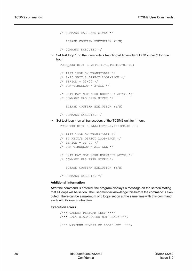
• Set test loop 1 on the transcoders handling all timeslots of PCM circuit 2 for one
hour.
TCSM_XXX:DIC> L:2:TESTL=1,PERIOD=01-00;
/* TEST LOOP ON TRANSCODER */
/* 8/16 KBIT/S DIRECT LOOP-BACK */
/* PERIOD = 01-00 */
/* PCM-TIMESLOT = 2-ALL */
/* UNIT MAY NOT WORK NORMALLY AFTER *//* COMMAND HAS BEEN GIVEN */
PLEASE CONFIRM EXECUTION (Y/N)
/* COMMAND EXECUTED */
• Set test loop 4 on all transcoders of the TCSM2 unit for 1 hour.
TCSM_XXX:DIC> L:ALL:TESTL=4,PERIOD=01-00;
/* TEST LOOP ON TRANSCODER */
/* 64 KBIT/S DIRECT LOOP-BACK */
/* PERIOD = 01-00 *//* PCM-TIMESLOT = ALL-ALL */
/* UNIT MAY NOT WORK NORMALLY AFTER */
/* COMMAND HAS BEEN GIVEN */
PLEASE CONFIRM EXECUTION (Y/N)
/* COMMAND EXECUTED */
Additional information
After the command is entered, the program displays a message on the screen stating
that all loops will be set on. The user must acknowledge this before the command is exe-
cuted. There can be a maximum of 5 loops set on at the same time with this command,
each with its own control time.
Execution errors
/*** CANNOT PERFORM TEST ***/
/*** LAST DIAGNOSTICS NOT READY ***/
/*** MAXIMUM NUMBER OF LOOPS SET ***/
8/10/2019 TCSM COMMAND.pdf
http://slidepdf.com/reader/full/tcsm-commandpdf 37/125
DN98513282
Issue 8-0
37
TCSM2 User Commands TCSM2 commands
Id:0900d805805a29e2
Confidential
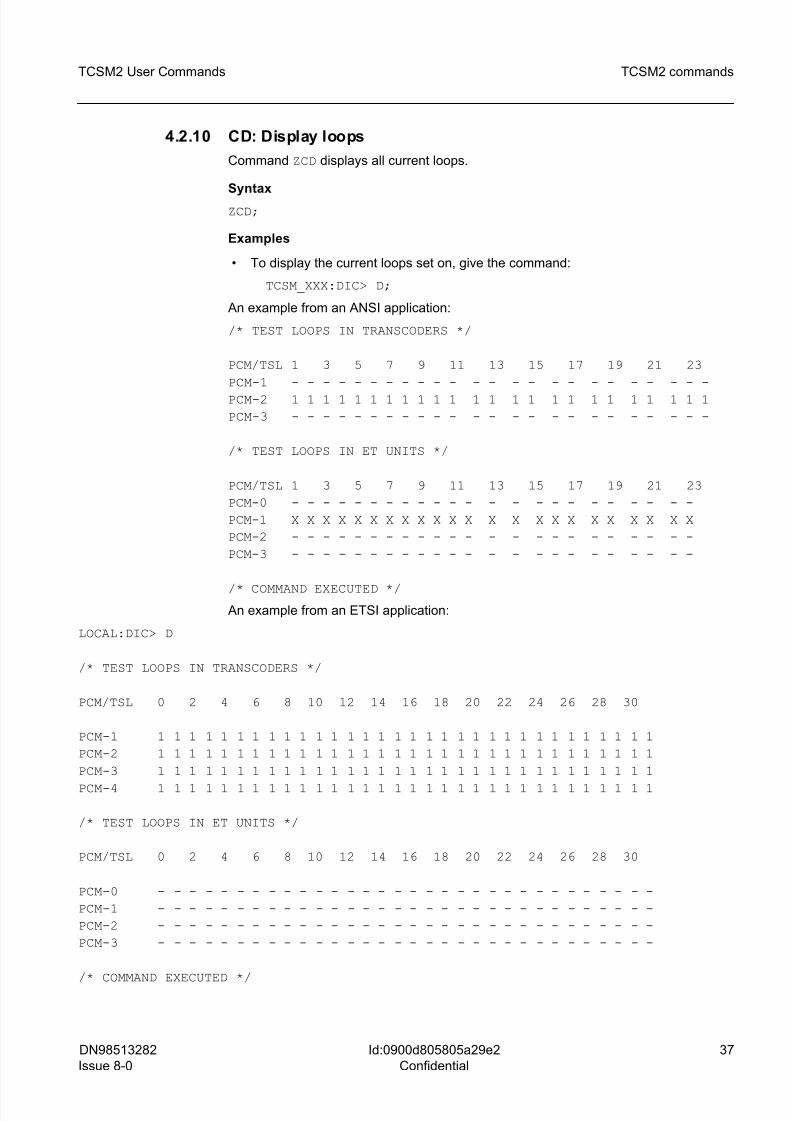
4.2.10 CD: Display loops
Command ZCD displays all current loops.
Syntax
ZCD;
Examples
• To display the current loops set on, give the command:
TCSM_XXX:DIC> D;
An example from an ANSI application:
/* TEST LOOPS IN TRANSCODERS */
PCM/TSL 1 3 5 7 9 11 13 15 17 19 21 23
PCM-1 - - - - - - - - - - - - - - - - - - - - - - - -
PCM-2 1 1 1 1 1 1 1 1 1 1 1 1 1 1 1 1 1 1 1 1 1 1 1 1
PCM-3 - - - - - - - - - - - - - - - - - - - - - - - -
/* TEST LOOPS IN ET UNITS */
PCM/TSL 1 3 5 7 9 11 13 15 17 19 21 23
PCM-0 - - - - - - - - - - - - - - - - - - - - - - -
PCM-1 X X X X X X X X X X X X X X X X X X X X X X X
PCM-2 - - - - - - - - - - - - - - - - - - - - - - -
PCM-3 - - - - - - - - - - - - - - - - - - - - - - -
/* COMMAND EXECUTED */
An example from an ETSI application:
LOCAL:DIC> D
/* TEST LOOPS IN TRANSCODERS */
PCM/TSL 0 2 4 6 8 10 12 14 16 18 20 22 24 26 28 30
PCM-1 1 1 1 1 1 1 1 1 1 1 1 1 1 1 1 1 1 1 1 1 1 1 1 1 1 1 1 1 1 1 1 1
PCM-2 1 1 1 1 1 1 1 1 1 1 1 1 1 1 1 1 1 1 1 1 1 1 1 1 1 1 1 1 1 1 1 1
PCM-3 1 1 1 1 1 1 1 1 1 1 1 1 1 1 1 1 1 1 1 1 1 1 1 1 1 1 1 1 1 1 1 1
PCM-4 1 1 1 1 1 1 1 1 1 1 1 1 1 1 1 1 1 1 1 1 1 1 1 1 1 1 1 1 1 1 1 1
/* TEST LOOPS IN ET UNITS */
PCM/TSL 0 2 4 6 8 10 12 14 16 18 20 22 24 26 28 30
PCM-0 - - - - - - - - - - - - - - - - - - - - - - - - - - - - - - - -
PCM-1 - - - - - - - - - - - - - - - - - - - - - - - - - - - - - - - -
PCM-2 - - - - - - - - - - - - - - - - - - - - - - - - - - - - - - - -
PCM-3 - - - - - - - - - - - - - - - - - - - - - - - - - - - - - - - -
/* COMMAND EXECUTED */

8/10/2019 TCSM COMMAND.pdf
http://slidepdf.com/reader/full/tcsm-commandpdf 38/125
38 DN98513282
Issue 8-0
TCSM2 User Commands
Id:0900d805805a29e2
Confidential
TCSM2 commands
• To display all active loops when there are no loop-backs set, give the command:
TCSM_XXX:DIC> D;
/* TEST LOOPS IN TRANSCODER */
PCM/TSL 1 3 5 7 9 11 13 15 17 19 21 23
PCM-1 - - - - - - - - - - - - - - - - - - - - - - -
PCM-2 1 1 1 1 1 1 1 1 1 1 1 1 1 1 1 1 1 1 1 1 1 1 1
PCM-3 - - - - - - - - - - - - - - - - - - - - - - -
/* TEST LOOPS IN ET UNITS */
PCM/TSL 1 3 5 7 9 11 13 15 17 19 21 23
PCM-0 - - - - - - - - - - - - - - - - - - - - - - -
PCM-1 - - - - - - - - - - - - - - - - - - - - - - -
PCM-2 - - - - - - - - - - - - - - - - - - - - - - -
PCM-3 - - - - - - - - - - - - - - - - - - - - - - -
/* COMMAND EXECUTED */
An example from an ETSI application:
/* TEST LOOPS IN TRANSCODERS */
PCM/TSL 0 2 4 6 8 10 12 14 16 18 20 22 24 26 28 30
PCM-1 - - - - - - - - - - - - - - - - - - - - - - - - - - -
PCM-2 - - - - - - - - - - - - - - - - - - - - - - - - - - -
PCM-3 - - - - - - - - - - - - - - - - - - - - - - - - - - -
/* TEST LOOPS IN ET UNITS */
PCM/TSL 0 2 4 6 8 10 12 14 16 18 20 22 24 26 28 30
PCM-0 - - - - - - - - - - - - - - - - - - - - - - - - - - -
PCM-1 - - - - - - - - - - - - - - - - - - - - - - - - - - -
PCM-2 - - - - - - - - - - - - - - - - - - - - - - - - - - -
PCM-3 - - - - - - - - - - - - - - - - - - - - - - - - - - -
/* COMMAND EXECUTED */
4.2.11 CR: Remove loops
Command ZCR allows you to remove all the current loops set on. Loop-backs may be
set through Exchange Terminals or Transcoders.
Syntax
ZCR;
Example
• To remove all the loops set on, give the command:
8/10/2019 TCSM COMMAND.pdf
http://slidepdf.com/reader/full/tcsm-commandpdf 39/125
DN98513282
Issue 8-0
39
TCSM2 User Commands TCSM2 commands
Id:0900d805805a29e2
Confidential
TCSM_XXX:DIC> R;
/* COMMAND EXECUTED */
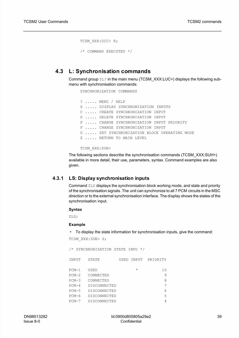
4.3 L: Synchronisation commands
Command group ZL? in the main menu (TCSM_XXX:LUC>) displays the following sub-
menu with synchronisation commands:
SYNCHRONIZATION COMMANDS
? ..... MENU / HELP
S ..... DISPLAY SYNCHRONIZATION INPUTS
C ..... CREATE SYNCHRONIZATION INPUT
D ..... DELETE SYNCHRONIZATION INPUTP ..... CHANGE SYNCHRONIZATION INPUT PRIORITY
F ..... CHANGE SYNCHRONIZATION INPUT
O ..... SET SYNCHRONIZATION BLOCK OPERATING MODE
Z ..... RETURN TO MAIN LEVEL
TCSM_XXX:SUH>
The following sections describe the synchronisation commands (TCSM_XXX:SUH>)
available in more detail, their use, parameters, syntax. Command examples are also
given.
4.3.1 LS: Display synchronisation inputs
Command ZLS displays the synchronisation block working mode, and state and priority
of the synchronisation signals. The unit can synchronize to all 7 PCM circuits in the MSC
direction or to the external synchronisation interface. The display shows the states of the
synchronisation input.
Syntax
ZLS;
Example
• To display the state information for synchronisation inputs, give the command:
TCSM_XXX:SUH> S;
/* SYNCHRONIZATION STATE INFO */
INPUT STATE USED INPUT PRIORITY
PCM-1 USED * 10
PCM-2 CONNECTED 9
PCM-3 CONNECTED 8
PCM-4 DISCONNECTED 7
PCM-5 DISCONNECTED 6
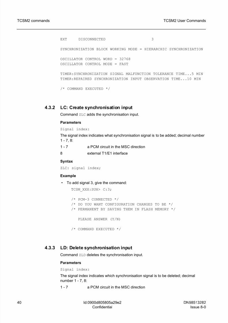
PCM-6 DISCONNECTED 5PCM-7 DISCONNECTED 4
8/10/2019 TCSM COMMAND.pdf
http://slidepdf.com/reader/full/tcsm-commandpdf 40/125
40 DN98513282
Issue 8-0
TCSM2 User Commands
Id:0900d805805a29e2
Confidential
TCSM2 commands
EXT DISCONNECTED 3
SYNCHRONIZATION BLOCK WORKING MODE = HIERARCHIC SYNCHRONIZATION
OSCILLATOR CONTROL WORD = 32768
OSCILLATOR CONTROL MODE = FAST
TIMER:SYNCHRONIZATION SIGNAL MALFUNCTION TOLERANCE TIME...5 MIN
TIMER:REPAIRED SYNCHRONIZATION INPUT OBSERVATION TIME...10 MIN
/* COMMAND EXECUTED */
4.3.2 LC: Create synchronisation input
Command ZLC adds the synchronisation input.
Parameters
Signal index:
The signal index indicates what synchronisation signal is to be added; decimal number
1 - 7, 8:
1 - 7 a PCM circuit in the MSC direction
8 external T1/E1 interface
Syntax
ZLC: signal index;
Example
• To add signal 3, give the command:
TCSM_XXX:SUH> C:3;
/* PCM-3 CONNECTED */
/* DO YOU WANT CONFIGURATION CHANGES TO BE */
/* PERMANENT BY SAVING THEM IN FLASH MEMORY */
PLEASE ANSWER (Y/N)
/* COMMAND EXECUTED */
4.3.3 LD: Delete synchronisation input
Command ZLD deletes the synchronisation input.
Parameters
Signal index:
The signal index indicates which synchronisation signal is to be deleted; decimal
number 1 - 7, 8:
1 - 7 a PCM circuit in the MSC direction
8/10/2019 TCSM COMMAND.pdf
http://slidepdf.com/reader/full/tcsm-commandpdf 41/125
DN98513282
Issue 8-0
41
TCSM2 User Commands TCSM2 commands
Id:0900d805805a29e2
Confidential
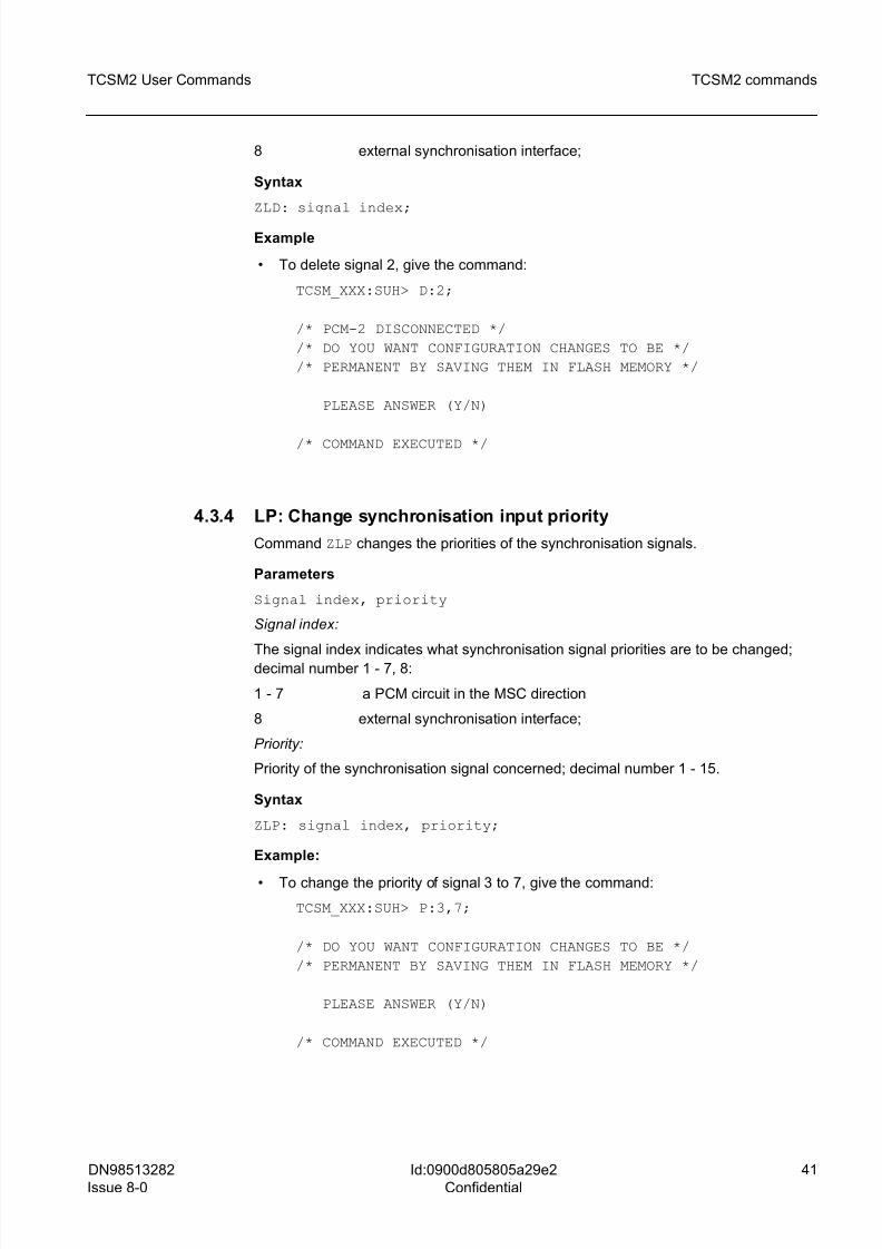
8 external synchronisation interface;
Syntax
ZLD: signal index;
Example
• To delete signal 2, give the command:
TCSM_XXX:SUH> D:2;
/* PCM-2 DISCONNECTED */
/* DO YOU WANT CONFIGURATION CHANGES TO BE */
/* PERMANENT BY SAVING THEM IN FLASH MEMORY */
PLEASE ANSWER (Y/N)
/* COMMAND EXECUTED */
4.3.4 LP: Change synchronisation input priority
Command ZLP changes the priorities of the synchronisation signals.
Parameters
Signal index, priority
Signal index:
The signal index indicates what synchronisation signal priorities are to be changed;decimal number 1 - 7, 8:
1 - 7 a PCM circuit in the MSC direction
8 external synchronisation interface;
Priority:
Priority of the synchronisation signal concerned; decimal number 1 - 15.
Syntax
ZLP: signal index, priority;
Example:
• To change the priority of signal 3 to 7, give the command:
TCSM_XXX:SUH> P:3,7;
/* DO YOU WANT CONFIGURATION CHANGES TO BE */
/* PERMANENT BY SAVING THEM IN FLASH MEMORY */
PLEASE ANSWER (Y/N)
/* COMMAND EXECUTED */
8/10/2019 TCSM COMMAND.pdf
http://slidepdf.com/reader/full/tcsm-commandpdf 42/125
42 DN98513282
Issue 8-0
TCSM2 User Commands
Id:0900d805805a29e2
Confidential
TCSM2 commands
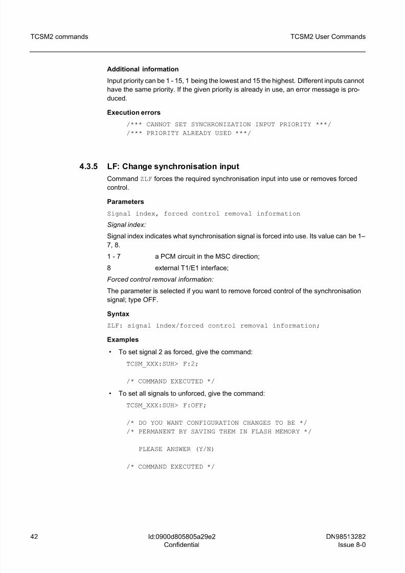
Additional information
Input priority can be 1 - 15, 1 being the lowest and 15 the highest. Different inputs cannot
have the same priority. If the given priority is already in use, an error message is pro-
duced.
Execution errors
/*** CANNOT SET SYNCHRONIZATION INPUT PRIORITY ***/
/*** PRIORITY ALREADY USED ***/
4.3.5 LF: Change synchronisation input
Command ZLF forces the required synchronisation input into use or removes forced
control.
Parameters
Signal index, forced control removal information
Signal index:
Signal index indicates what synchronisation signal is forced into use. Its value can be 1–
7, 8.
1 - 7 a PCM circuit in the MSC direction;
8 external T1/E1 interface;
Forced control removal information:
The parameter is selected if you want to remove forced control of the synchronisation
signal; type OFF.
Syntax
ZLF: signal index/forced control removal information;
Examples
• To set signal 2 as forced, give the command:
TCSM_XXX:SUH> F:2;
/* COMMAND EXECUTED */
• To set all signals to unforced, give the command:
TCSM_XXX:SUH> F:OFF;
/* DO YOU WANT CONFIGURATION CHANGES TO BE */
/* PERMANENT BY SAVING THEM IN FLASH MEMORY */
PLEASE ANSWER (Y/N)
/* COMMAND EXECUTED */
8/10/2019 TCSM COMMAND.pdf
http://slidepdf.com/reader/full/tcsm-commandpdf 43/125
DN98513282
Issue 8-0
43
TCSM2 User Commands TCSM2 commands
Id:0900d805805a29e2
Confidential
4.3.6 LO: Set synchronisation block operating mode
Command ZLO determines the synchronisation block's operating mode (either hierarchi-
cal or plesiochronous), the oscillator control word and adjustment mode and the time
parameters of the synchronisation signal.
Parameters
operating mode:
The parameter's value indicates if the operating state is to be changed to hierarchical or
to plesiochronous; type:
H hierarchical synchronisation
P plesiochronous working mode
oscillator control mode specification (M):
NORM normal
FAST fast
oscillator control word specification (W):
A number between 0 and 65534 (for plesiochronous synchronisation only).
oscillator timing parameters:
A number between 1 and 240. This is the time in minutes.
TP Time for tolerating malfunction in input signal.
TR Observation time for repaired synchronisation.
Syntax
ZLO: operating mode, oscillator control, oscillator timing;ZLO:M = oscillator control mode specification;
ZLO:W = oscillator control word specification;
ZLO:TP or TR = oscillator timing;
g Parameter W can only be used in the plesiochronous working mode.
Example
• To select hierarchical synchronisation as the synchronisation block's working state,
give the command:
TCSM_XXX:SUH> O:H;
/* SYNCHRONIZATION BLOCK WORKING MODE CHANGED TO */
/* HIERARCHICAL SYNCHRONIZATION */
/* COMMAND EXECUTED */
To select fast adjustment as the oscillator adjustment mode, give the command:
TCSM_XXX:SUH> O:M=FAST;
/* COMMAND EXECUTED */
• To select normal control as the oscillator control mode, give the command:
8/10/2019 TCSM COMMAND.pdf
http://slidepdf.com/reader/full/tcsm-commandpdf 44/125
44 DN98513282
Issue 8-0
TCSM2 User Commands
Id:0900d805805a29e2
Confidential
TCSM2 commands
TCSM_XXX:SUH> O:M=NORM;
/* COMMAND EXECUTED */
• To modify the oscillator control word, give the command:TCSM_XXX:SUH> O:W=10000;
/* COMMAND EXECUTED */
• To modify the oscillator timing parameter, give the command:
TCSM_XXX:SUH> O:TP=15;
/* DO YOU WANT CONFIGURATION CHANGES TO BE */
/* PERMANENT BY SAVING THEM IN FLASH MEMORY */
PLEASE ANSWER (Y/N)
/* COMMAND EXECUTED */
4.4 G: General configuration commands
Command group ZG? in the main menu (TCSM_XXX:LUC>) displays the following sub-
menu with general configuration commands:
GENERAL CONFIGURATION COMMANDS
? ..... MENU / HELPT ..... DISPLAY TCSM2 HARDWARE CONFIGURATION
I ..... DISPLAY PROGRAM IDENTIFICATION CODES
L ..... SET PCM LINE TERMINAL TYPE
H ..... SET THROUGH CONNECTED CHANNELS
U ..... UPDATE SOFTWARE IN FLASH MEMORY
W ..... DISPLAY TRANSCODER SOFTWARE
S ..... SAVE CONFIGURATION
N ..... DOWNLOAD CONFIGURATION FROM PC
O ..... UPLOAD CONFIGURATION TO PC
V ..... SET HW IDENTIFICATION
P ..... CHANGE PASSWORD
C ..... SET DEFAULT CONFIGURATION
Z ..... RETURN TO MAIN LEVEL
TCSM_XXX:GCC>
The following sections describe the general configuration commands
(TCSM_XXX:GCC>) available in more detail, their use, parameters, syntax and
command examples.
4.4.1 GT: Display TCSM2 hardware configuration
Command ZGT displays the TCSM2 unit's hardware configuration, working state,
working standard and the companding law used.
8/10/2019 TCSM COMMAND.pdf
http://slidepdf.com/reader/full/tcsm-commandpdf 45/125
DN98513282
Issue 8-0
45
TCSM2 User Commands TCSM2 commands
Id:0900d805805a29e2
Confidential
Syntax
ZGT;
Parameters
Working standard:
ANSI ANSI (US) standard
ETSI ETSI (European) standard
Working state:
• NA, converter mode does not apply to ETSI standard
ON converter mode on (ANSI-C)
OFF converter mode off (ANSI)
Companding law:
A-LAW A law
U-LAW µ law
Example
• To display the TCSM2 unit's equipment data, give the command:
TCSM_XXX:GCC> T;
/* TCSM2 EQUIPMENT INFO */
STANDARD CONVERTER COMPANDING LAW
ANSI OFF U-LAW
UNIT VERSION INTERCHANGE- STATE
TYPE ABILITY CODE
TRCO 1 A TE-EX
ET2A-0 - -
ET2A-1 - -
ET2A-2 - -
TR12-0 1 A
TR12-1 1 A
TR12-2 1 A
TR12-3 1 A
TR12-4 1 ATR12-5 1 A
TR12-6 1 A
TR12-7 1 A
/* COMMAND EXECUTED */
Additional information
The version and interchangeability information is not available for the ET2 plug-in units,
because they do not support that feature. If a TR unit is faulty, no version and inter-
changeability information is available either.
8/10/2019 TCSM COMMAND.pdf
http://slidepdf.com/reader/full/tcsm-commandpdf 46/125
46 DN98513282
Issue 8-0
TCSM2 User Commands
Id:0900d805805a29e2
Confidential
TCSM2 commands
Execution errors
/*** FLASH MEMORY OPERATION FAILURE ***/
4.4.2 GI: Display program identification codes
Command ZGI displays the identification codes of programs in a unit. Hitting the ESC
key interrupts the execution of the command.
Parameters
Plug-in unit type;
The type indicates what plug-in unit software identification codes are displayed.
TRCO TRCO plug-in unit
ET ET2A/ET2E plug-in unit
TR TR12/TR16 plug-in unit
Syntax
ZGI: plug-in unit type;
Examples
• To display TRCO plug-in unit software identification codes, give the command:
TCSM_XXX:GCC> I:TRCO;
/* TRCO PROGRAM IDENTIFICATION */
FB04.002E CID: TC1_PXMX.PAC 6.2-0 96/11/02
/* COMMAND EXECUTED */
• To display TR12/TR16 plug-in unit software identification code, give the command:
TCSM_XXX:GCC> I:TR;
The command now displays the running DSP_CODE separately for every PCM line.
/* TR PROGRAM IDENTIFICATION */
1. 4000.0005: PID: TDL_PXMX.PRM 1.1-0 96/12/01
2. 4000.0005: PID: TDL_PXMX.PRM 1.1-0 96/12/01
3. 4000.0005: PID: TDL_PXMX.PRM 1.1-0 96/12/01
4. 4000.0005: PID: TDL_PXMX.PRM 1.1-0 96/12/01
5. PCM_line not in use
6. PCM_line not in use
7. PCM_line not in use
/* COMMAND EXECUTED */
• To display ET2A/ET2E plug-in unit software identification code, give the command:
TCSM_XXX:GCC> I:ET;
8/10/2019 TCSM COMMAND.pdf
http://slidepdf.com/reader/full/tcsm-commandpdf 47/125
DN98513282
Issue 8-0
47
TCSM2 User Commands TCSM2 commands
Id:0900d805805a29e2
Confidential
/* ET PROGRAM IDENTIFICATION */
480A.0004 ET5RAMQK.PAC 4.5-0 99/10/12
/* COMMAND EXECUTED */
4.4.3 GL: Set PCM line terminal type
Command ZGL is used to choose the type of the TCSM2 unit's PCM line terminal type
(towards the BSC), ANSI converter mode and the companding law used.
Parameters
PCM line type:
The type indicates the BSC-direction PCM line type. Type: ANSI/ETSI
ANSI converter mode:
Possible only if PCM line type is ANSI. Type: CONV
Companding law:
Possible only if the PCM line type is ANSI.
A_LAW A-law
U_LAW µ-law
Syntax
ZGL: PCM line type (, ANSI converter mode) (, companding law);
Examples
• To select ANSI as the BSC (PCM) circuit terminal type, give the command:
TCSM_XXX:GCC> L:ANSI;
/* ALL CALLS WILL BE CANCELLED DUE */
/* TO GIVEN COMMAND */
PLEASE CONFIRM EXECUTION (Y/N)
/* COMMAND EXECUTED */
• To select ANSI as the BSC (PCM) circuit terminal type and set the converter modeon (companding law will then be A-law), give the command:
TCSM_XXX:GCC> L:ANSI:CONV;
/* ALL CALLS WILL BE CANCELLED DUE */
/* TO GIVEN COMMAND */
PLEASE CONFIRM EXECUTION (Y/N)
/* COMMAND EXECUTED */
Additional informationThe command restarts the whole TCSM2 unit.
8/10/2019 TCSM COMMAND.pdf
http://slidepdf.com/reader/full/tcsm-commandpdf 48/125
48 DN98513282
Issue 8-0
TCSM2 User Commands
Id:0900d805805a29e2
Confidential
TCSM2 commands
Execution errors
/*** FLASH MEMORY OPERATION FAILURE ***/
/*** MESSAGE TIMEOUT ***/
4.4.4 GH: Set through connected channels
Command ZGH sets through-connection on or off for the selected channel.
Parameters
MSC direction PCM circuit index, timeslot, BSC direction PCM
circuit timeslot
BSC direction PCM circuit timeslot:
The parameter selects a timeslot from the BSC direction PCM circuit to be through-con-nected; decimal number 2 - 24 (ANSI), 2-31 (ETSI).
MSC direction PCM circuit index:
The parameter indicates where in the MSC direction PCM circuit the selected channel
is located; decimal number 1 - 7
Timeslot:
Timeslot indicates a certain channel of the MSC direction PCM circuit; decimal number
1 - 24 (ANSI), 1-31 (ETSI).
Syntax
ZGH:BSC direction PCM circuit timeslot, (MSC direction PCMcircuit index, timeslot);
Examples
• To set BSC direction PCM circuit timeslot 22 through-connected to MSC direction
PCM circuit 2 timeslot 16, give the command:
TCSM_XXX:GCC> H:22,2,16;
/* THROUGH CONNECTED CHANNEL */
BSC PCM-TIMESLOT = 0-22
MSC PCM-TIMESLOT = 2-16 CONNECTION ON
PLEASE CONFIRM (Y/N)
/* COMMAND EXECUTED */
• To delete BSC direction PCM circuit timeslot 22 through-connection to the MSC
direction PCM circuit 2 timeslot 16, give the command:
TCSM_XXX:GCC> H:22;
/* THROUGH CONNECTED CHANNEL */
8/10/2019 TCSM COMMAND.pdf
http://slidepdf.com/reader/full/tcsm-commandpdf 49/125
DN98513282
Issue 8-0
49
TCSM2 User Commands TCSM2 commands
Id:0900d805805a29e2
Confidential
BSC PCM-TIMESLOT = 0-22
CONNECTION OFF
PLEASE CONFIRM (Y/N)
/* COMMAND EXECUTED */
4.4.5 GU: Update software in flash memory
Command ZGU updates the software of either the ET2A/ET2E, the TRCO or the
TR12/TR16 plug-in unit in the Flash memory.
g This command is available only when the LAPD connection to the BSC is not estab-
lished or working.
Parameters
Plug-in unit type:
The parameter indicates which plug-in unit's software is updated.
TRCO TRCO plug-in unit
TR TR12/TR16 plug-in unit
ET ET2A/ET2E(-S/C/SC) plug-in unit
Syntax
ZGU: plug-in unit type;
Examples
• To update TRCO plug-in unit software, first give the command below and then start
the data transfer using Kermit protocol:
TCSM_XXX:GCC> U:TRCO;
READY TO RECEIVE PROGRAM CODE
(start data transfer using Kermit protocol)
The unit restarts and the program is executed from the boot EPROM. When the software
is updated, the TRCO unit is restarted and it begins to perform the program code just
loaded.
• To update ET2A/ET2E plug-in unit software, first give the command below and thenstart the data transfer using Kermit protocol:
TCSM_XXX:GCC> U:ET;
PLEASE CONFIRM (Y/N)
READY TO RECEIVE PROGRAM CODE
(start data transfer using Kermit protocol)
PROGRAM TRANSFER SUCCESSFULLY COMPLETED
/* COMMAND EXECUTED */
8/10/2019 TCSM COMMAND.pdf
http://slidepdf.com/reader/full/tcsm-commandpdf 50/125
50 DN98513282
Issue 8-0
TCSM2 User Commands
Id:0900d805805a29e2
Confidential
TCSM2 commands
• To update transcoder software, first give the command below and then start data
transfer using Kermit protocol:
TCSM_XXX:GCC> U:TR;
PLEASE CONFIRM (Y/N)
SELECT TRANSCODER SOFTWARE:
NBR ADDRESS USED SW ID STRING
1. 4000.0000: * PID: TDL_PXMX.PRM 1.1-0 95/12/01
2. 6000.0000: PID: TDL_PXMX.PRM 1.2-0 95/12/02
3. 5000.0000: FREE CODE MEMORY AREA
ENTER NUMBER : x
READY TO RECEIVE PROGRAM CODE
(start data transfer using Kermit protocol)
PROGRAM TRANSFER SUCCESSFULLY COMPLETED
/* COMMAND EXECUTED */
To update transcoder software in the TCSM2A-C, first give the command and then start
the data transfer using Kermit protocol:
TCSM_XXX:GCC> U:ET;
PLEASE CONFIRM (Y/N)
SELECT EXCHANGE TERMINAL SOFTWARE:
NBR ET TYPE ID STRING
1. ET2E ET2RAMQA.PAC 1.25-1 96/10/02
2. ET2A ET5RAMQA.PAC 1.15-1 96/02/14
ENTER NUMBER : x
READY TO RECEIVE PROGRAM CODE
(start data transfer using Kermit protocol)
PROGRAM TRANSFER SUCCESSFULLY COMPLETED
/* COMMAND EXECUTED */
Additional information
There may be several versions of the transcoder software in the Flash memory. When
updating the transcoder software, after entering the command, details of those versions
are displayed and the user selects one of them. This selected version of the software is
replaced by a new version.
A message is displayed when the TCSM2 unit is ready to start receiving the program
code. After the message, data transfer is started from the PC according to Kermit pro-
8/10/2019 TCSM COMMAND.pdf
http://slidepdf.com/reader/full/tcsm-commandpdf 51/125
DN98513282
Issue 8-0
51
TCSM2 User Commands TCSM2 commands
Id:0900d805805a29e2
Confidential
tocol. Parameters relating to the protocol are set as fixed at the receiving end and must
be selected correspondingly at the transmission end before starting data transfer. On
completion of data transfer a transfer successful message is displayed.
TRCO Kermit supports: • packet length up to 1000 bytes
• check sum: 1- byte, 2-byte or CRC (default setting)
• zip packing of the identical consecutive characters
Execution errors
/*** PROGRAM TRANSFER FAILED ***/
/*** FLASH MEMORY OPERATION FAILURE ***/
/*** COMMAND NOT ALLOWED ***/
/*** LAPD IS WORKING ***/
4.4.6 GW: Display transcoder software
Command ZGW displays the software to be used in the transcoder from the versions in
the Flash memory.
Syntax
ZGW;
Example
• To display the software to be used in the transcoder, give the command:
TCSM_XXX:GCC> W;
SELECT TRANSCODER SOFTWARE:
NBR ADDRESS USED SW ID STRING
1. 4000.0000: * PID: TDL_PXMX.PRM 1.1-0 96/12/01
2. 6000.0000: PID: TDL_PXMX.PRM 1.2-0 96/12/02
3. 5000.0000: PID: TDL_PXMX.PRM 1.3-0 96/12/03
/* COMMAND EXECUTED */
Additional information
After the command is given, version data of transcoder software is displayed.
4.4.7 GS: Save configuration
Command ZGS saves configuration changes to the Flash memory.
Syntax
ZGS;
8/10/2019 TCSM COMMAND.pdf
http://slidepdf.com/reader/full/tcsm-commandpdf 52/125
52 DN98513282
Issue 8-0
TCSM2 User Commands
Id:0900d805805a29e2
Confidential
TCSM2 commands
Example
• To save configuration data to non-volatile (Flash) memory, give the command:
TCSM_XXX:GCC> S;
/* DO YOU WANT CONFIGURATION CHANGES TO BE */
/* PERMANENT BY SAVING THEM IN FLASH MEMORY */
PLEASE ANSWER (Y/N)
/* COMMAND EXECUTED */
Additional information
Configuration changes made with other commands are saved in RAM memory.
The local application program reads the configuration data of the plug-in units from the
RAM memory and saves them to non-volatile memory. The local application programrequires the user to confirm the operation before it will perform it.
4.4.8 GN: Download configuration from PC
The command ZGN is used to receive information from the configuration file of the PC
using Kermit protocol. This command is only possible in a local session.
Syntax
ZGN;
Examples
• To receive the active configuration from the PC, first give the command below and
then start the data transfer using Kermit protocol:
TCSM_XXX:GCC> N;
/* UNIT MAY NOT WORK NORMALLY DUE */
/* TO GIVEN COMMAND */
PLEASE, CONFIRM EXECUTION (Y/N)
THE TRCO IS READY TO RECEIVE THE CONFIGURATION FILE.START KERMIT FILE SEND FROM YOUR COMPUTER.
/* CONFIGURATION FILE UPLOAD */
/* SUCCESSFULLY COMPLETED */
/* COMMAND EXECUTED */
Execution errors
/*** PROGRAM TRANSFER FAILED ***/
/*** FLASH MEMORY OPERATION FAILURE ***/
8/10/2019 TCSM COMMAND.pdf
http://slidepdf.com/reader/full/tcsm-commandpdf 53/125
DN98513282
Issue 8-0
53
TCSM2 User Commands TCSM2 commands
Id:0900d805805a29e2
Confidential
/*** KERMIT TRANSFER FAILED ***/
/*** TOO MANY RETRIES ***/
4.4.9 GO: Upload configuration to PC
The command ZGO is used to send the present active configuration to the PC using
Kermit protocol. The command combines the active files in the RAM memory (ETCONF,
TR1CON and CLKCON) into one file and sends it to the PC. The command is only
possible in a local session.
Syntax
ZGO;
Example
• To send the active configuration to the PC, first give the command below and then
start the data transfer using Kermit protocol:
TCSM_XXX:GCC> O;
/* UNIT MAY NOT WORK NORMALLY */
/* AFTER COMMAND HAS BEEN GIVEN */
PLEASE CONFIRM (Y/N)
THE TRCO IS READY TO SEND THE CONFIGURATION FILE
START KERMIT FILE RECEIVE FROM YOUR COMPUTER
/* CONFIGURATION FILE UPLOAD */
/* SUCCESSFULLY COMPLETED */
/* COMMAND EXECUTED */
Execution errors
/*** PROGRAM TRANSFER FAILED ***/
/*** FLASH MEMORY OPERATION FAILURE ***/
/*** KERMIT TRANSFER FAILED ***//*** TOO MANY RETRIES ***/
4.4.10 GV: Set HW identification
Command ZGV sets the TRCO plug-in unit's version and interchangeability code.
Parameters
Version type, interchangeability type
Version type:
Version type indicates the plug-in unit's version data; decimal number.
8/10/2019 TCSM COMMAND.pdf
http://slidepdf.com/reader/full/tcsm-commandpdf 54/125
54 DN98513282
Issue 8-0
TCSM2 User Commands
Id:0900d805805a29e2
Confidential
TCSM2 commands
Interchangeability type:
Interchangeability type indicates the plug-in unit's interchangeability data; any letter.
Syntax
ZGV: version type, interchangeability type;
Example
• To set plug-in unit's version data as 2 and interchangeability code C, give the
command:
TCSM_XXX:GCC> V:2,C;
/* COMMAND EXECUTED */
4.4.11 GP: Change password
Command ZGP changes the local application session password. The user-names USER
and EXPERT both have their own password and the change applies to the password
with which the local application session was opened.
Syntax
ZGP;
Example
• To change the local application session password, give the command:
TCSM_XXX:GCC> P;
OLD PASSWORD>
NEW PASSWORD>
VERIFICATION>
/* COMMAND EXECUTED */
Additional information
After entering the command, the user is asked for the old password. If it is given cor-
rectly, the new password is asked for twice. The user's passwords are not displayed on
screen. The new password is then valid.
4.4.12 GC: Set default configuration
Command ZGC sets the default configuration (= factory settings) for the TCSM2 unit.
Syntax
ZGC;
Example
To set the default configuration, give the command:
8/10/2019 TCSM COMMAND.pdf
http://slidepdf.com/reader/full/tcsm-commandpdf 55/125
DN98513282
Issue 8-0
55
TCSM2 User Commands TCSM2 commands
Id:0900d805805a29e2
Confidential
TCSM_XXX:GCC> C;
/* ALL CALLS WILL BE CANCELLED */
/* DUE TO GIVEN COMMAND */
PLEASE CONFIRM EXECUTION (Y/N)
RESTARTING TCSM UNIT ...
4.5 R: Transcoder configuration commands
Command group ZR? in the main menu (TCSM_XXX:LUC>) displays the following sub-
menu with transcoder configuration commands:
TRANSCODER CONFIGURATION COMMANDS
? ..... MENU / HELP
C ..... DISPLAY CHANNEL CONFIGURATION
X ..... SET DOWNLINK DTX
A ..... SET ADAPTIVE GAIN ADJUSTMENT IN DOWNLINK DIRECTION
F ..... SET FIXED GAIN ADJUSTMENT
S ..... SET TIME ALIGNMENT
U ..... SET ACOUSTIC ECHO CANCELLATION (AEC)
Y ..... SET NOISE SUPPRESSION (NS)
N ..... SET TANDEM FREE OPERATION (TFO)
M ..... START TRAFFIC CHANNEL MONITORING
T ..... MODIFY ALARM LIMITS
O ..... DISPLAY ALARM LIMITS
R .... SET TRANSCODER PCM TYPES
D ..... DISPLAY TRANSCODER PCM TYPES
Z ..... RETURN TO MAIN LEVEL
TCSM_XXX:TCC>
The following sections describe the transcoder configuration commands
(TCSM_XXX:TCC>) available in more detail, their use, parameters, syntax and
command examples.
4.5.1 RC: Display channel configuration
Command ZRC displays the TR12/TR16 plug-in units' channel-specific parameters.
Parameters
PCM circuit index, timeslot, parameter;
PCM circuit index:
The identifier indicates which MSC direction PCM circuit channel parameters are to be
displayed; decimal number 1 to 7. In ANSI-C mode decimal number between 2 and 7.
Timeslot:
Timeslot shows a certain PCM circuit channel; decimal number 1 to 24 (ANSI), 1 to 31(ETSI).
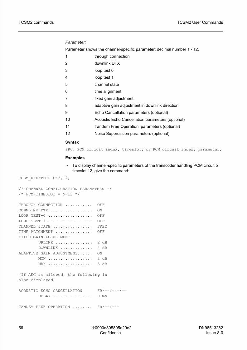
8/10/2019 TCSM COMMAND.pdf
http://slidepdf.com/reader/full/tcsm-commandpdf 56/125
56 DN98513282
Issue 8-0
TCSM2 User Commands
Id:0900d805805a29e2
Confidential
TCSM2 commands
Parameter:
Parameter shows the channel-specific parameter; decimal number 1 - 12.
1 through connection
2 downlink DTX
3 loop test 0
4 loop test 1
5 channel state
6 time alignment
7 fixed gain adjustment
8 adaptive gain adjustment in downlink direction
9 Echo Cancellation parameters (optional)
10 Acoustic Echo Cancellation parameters (optional)
11 Tandem Free Operation parameters (optional)
12 Noise Suppression parameters (optional)
Syntax
ZRC: PCM circuit index, timeslot; or PCM circuit index: parameter;
Examples
• To display channel-specific parameters of the transcoder handling PCM circuit 5
timeslot 12, give the command:
TCSM_XXX:TCC> C:5,12;
/* CHANNEL CONFIGURATION PARAMETERS */
/* PCM-TIMESLOT = 5-12 */
THROUGH CONNECTION ........... OFF
DOWNLINK DTX ................. ON
LOOP TEST-0 .................. OFF
LOOP TEST-1 .................. OFF
CHANNEL STATE ................ FREE
TIME ALIGNMENT ............... OFF
FIXED GAIN ADJUSTMENT
UPLINK ............... 2 dB
DOWNLINK ............. 4 dB
ADAPTIVE GAIN ADJUSTMENT...... ON
MIN .................. 2 dB
MAX .................. 5 dB
(If AEC is allowed, the following is
also displayed)
ACOUSTIC ECHO CANCELLATION FR/--/---/-—
DELAY ................ 0 ms
TANDEM FREE OPERATION ........ FR/--/---
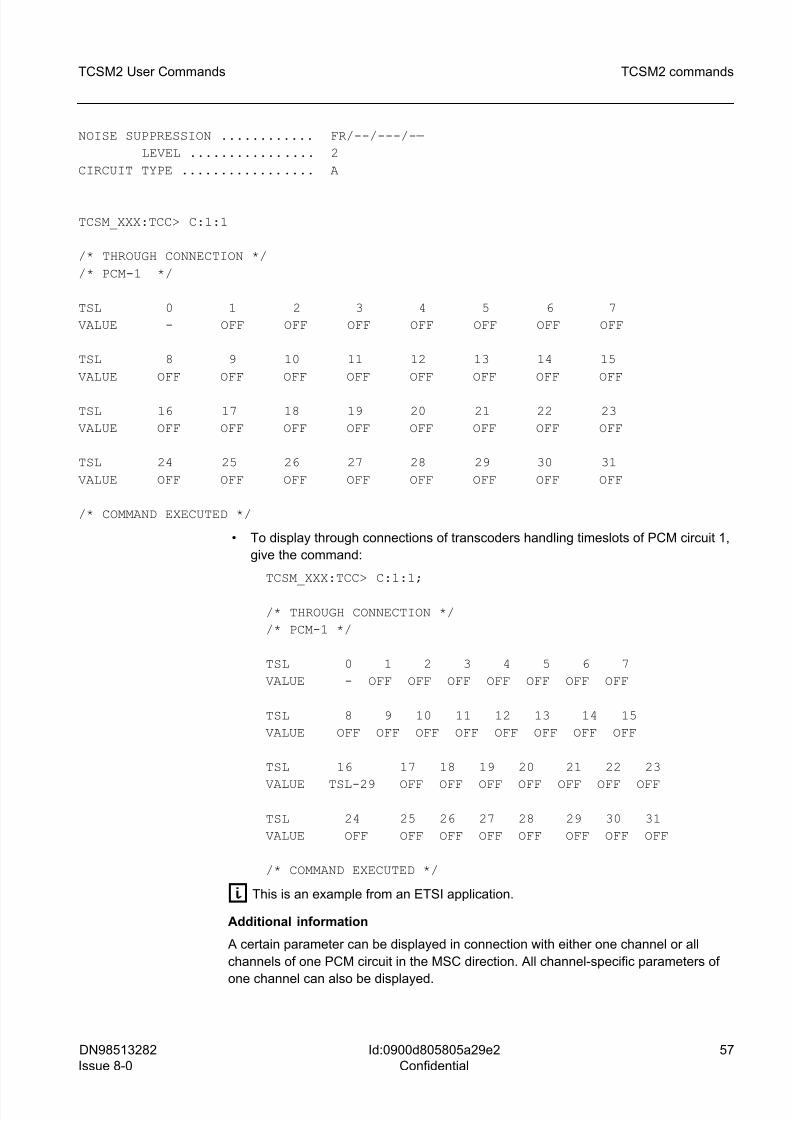
8/10/2019 TCSM COMMAND.pdf
http://slidepdf.com/reader/full/tcsm-commandpdf 57/125
DN98513282
Issue 8-0
57
TCSM2 User Commands TCSM2 commands
Id:0900d805805a29e2
Confidential
NOISE SUPPRESSION ............ FR/--/---/-—
LEVEL ................ 2
CIRCUIT TYPE ................. A
TCSM_XXX:TCC> C:1:1
/* THROUGH CONNECTION */
/* PCM-1 */
TSL 0 1 2 3 4 5 6 7
VALUE - OFF OFF OFF OFF OFF OFF OFF
TSL 8 9 10 11 12 13 14 15
VALUE OFF OFF OFF OFF OFF OFF OFF OFF
TSL 16 17 18 19 20 21 22 23
VALUE OFF OFF OFF OFF OFF OFF OFF OFF
TSL 24 25 26 27 28 29 30 31
VALUE OFF OFF OFF OFF OFF OFF OFF OFF
/* COMMAND EXECUTED */
• To display through connections of transcoders handling timeslots of PCM circuit 1,
give the command:
TCSM_XXX:TCC> C:1:1;
/* THROUGH CONNECTION */
/* PCM-1 */
TSL 0 1 2 3 4 5 6 7
VALUE - OFF OFF OFF OFF OFF OFF OFF
TSL 8 9 10 11 12 13 14 15
VALUE OFF OFF OFF OFF OFF OFF OFF OFF
TSL 16 17 18 19 20 21 22 23
VALUE TSL-29 OFF OFF OFF OFF OFF OFF OFF
TSL 24 25 26 27 28 29 30 31
VALUE OFF OFF OFF OFF OFF OFF OFF OFF
/* COMMAND EXECUTED */
g This is an example from an ETSI application.
Additional information
A certain parameter can be displayed in connection with either one channel or all
channels of one PCM circuit in the MSC direction. All channel-specific parameters of
one channel can also be displayed.
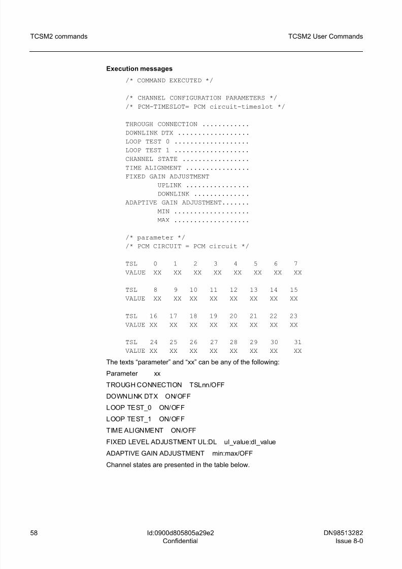
8/10/2019 TCSM COMMAND.pdf
http://slidepdf.com/reader/full/tcsm-commandpdf 58/125
58 DN98513282
Issue 8-0
TCSM2 User Commands
Id:0900d805805a29e2
Confidential
TCSM2 commands
Execution messages
/* COMMAND EXECUTED */
/* CHANNEL CONFIGURATION PARAMETERS *//* PCM-TIMESLOT= PCM circuit-timeslot */
THROUGH CONNECTION ............
DOWNLINK DTX ..................
LOOP TEST 0 ...................
LOOP TEST 1 ...................
CHANNEL STATE .................
TIME ALIGNMENT ................
FIXED GAIN ADJUSTMENT
UPLINK ................
DOWNLINK ..............
ADAPTIVE GAIN ADJUSTMENT.......
MIN ...................
MAX ...................
/* parameter */
/* PCM CIRCUIT = PCM circuit */
TSL 0 1 2 3 4 5 6 7
VALUE XX XX XX XX XX XX XX XX
TSL 8 9 10 11 12 13 14 15
VALUE XX XX XX XX XX XX XX XX
TSL 16 17 18 19 20 21 22 23
VALUE XX XX XX XX XX XX XX XX
TSL 24 25 26 27 28 29 30 31
VALUE XX XX XX XX XX XX XX XX
The texts “parameter” and “xx” can be any of the following:
Parameter xx
TROUGH CONNECTION TSLnn/OFF
DOWNLINK DTX ON/OFFLOOP TEST_0 ON/OFF
LOOP TEST_1 ON/OFF
TIME ALIGNMENT ON/OFF
FIXED LEVEL ADJUSTMENT UL:DL ul_value:dl_value
ADAPTIVE GAIN ADJUSTMENT min:max/OFF
Channel states are presented in the table below.
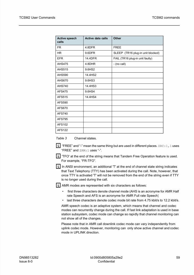
8/10/2019 TCSM COMMAND.pdf
http://slidepdf.com/reader/full/tcsm-commandpdf 59/125
DN98513282
Issue 8-0
59
TCSM2 User Commands TCSM2 commands
Id:0900d805805a29e2
Confidential
g “FREE” and “-” mean the same thing but are used in different places. ZRC:1,1 uses
“FREE” and ZRM:1 uses “-”.
g 'TFO' at the end of the string means that Tandem Free Operation feature is used.
For example, “FR-TFO”.
g In ANSI environment, an additional 'T' at the end of channel state string indicates
that Text Telephony (TTY) has been activated during the call. Note, however, that
once TTY is activated 'T' will not be removed from the end of the string even if TTY
is no longer used during the call.
g AMR modes are represented with six characters as follows:
• first three characters denote channel mode (AHS is an acronyme for AMR Halfrate Speech and AFS is an acronyme for AMR Full rate Speech)
• last three characters denote codec mode bit rate from 4.75 kbit/s to 12.2 kbit/s.
AMR speech codec is an adaptive system, which means that channel and codec
modes can recurrently change during the call. If fast link adaptation is used in base
station subsystem, codec mode can change so rapidly that channel monitoring can
not show all of the changes.
Please note that in AMR call downlink codec mode can vary independently from
uplink codec mode. However, monitoring can only show active channel and codec
mode in UPLINK direction.
Active speech
calls
Active data calls Other
FR 4.8DFR FREE
HR 9.6DFR SLEEP (TR16 plug-in unit blocked)
EFR 14.4DFR FAIL (TR16 plug-in unit faulty)
AHS475 4.8DHR - (no call)
AHS515 9.6HS2
AHS590 14.4HS2
AHS670 9.6HS3
AHS740 14.4HS3
AFS475 9.6HS4
AFS515 14.4HS4
AFS590
AFS670
AFS740
AFS795
AFS102
AFS122
Table 3 Channel states.
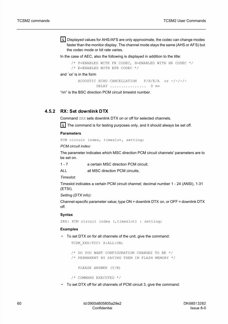
8/10/2019 TCSM COMMAND.pdf
http://slidepdf.com/reader/full/tcsm-commandpdf 60/125
60 DN98513282
Issue 8-0
TCSM2 User Commands
Id:0900d805805a29e2
Confidential
TCSM2 commands
g Displayed values for AHS/AFS are only approximate, the codec can change modes
faster than the monitor display. The channel mode stays the same (AHS or AFS) but
the codec mode or bit rate varies.
In the case of AEC, also the following is displayed in addition to the title:
/* F=ENABLED WITH FR CODEC, H=ENABLED WITH HR CODEC */
/* E=ENABLED WITH EFR CODEC */
and `xx' is in the form
ACOUSTIC ECHO CANCELLATION F/H/E/A or -/-/-/-
DELAY ................ 0 ms
“nn” is the BSC direction PCM circuit timeslot number.
4.5.2 RX: Set downlink DTXCommand ZRX sets downlink DTX on or off for selected channels.
g The command is for testing purposes only, and it should always be set off.
Parameters
PCM circuit index, timeslot, setting;
PCM circuit index:
The parameter indicates which MSC direction PCM circuit channels' parameters are to
be set on.
1 - 7 a certain MSC direction PCM circuit;
ALL all MSC direction PCM circuits;
Timeslot:
Timeslot indicates a certain PCM circuit channel; decimal number 1 - 24 (ANSI), 1-31
(ETSI).
Setting (DTX info):
Channel-specific parameter value; type ON = downlink DTX on, or OFF = downlink DTX
off.
Syntax
ZRX: PCM circuit index (,timeslot) : setting;
Examples
• To set DTX on for all channels of the unit, give the command:
TCSM_XXX:TCC> X:ALL:ON;
/* DO YOU WANT CONFIGURATION CHANGES TO BE */
/* PERMANENT BY SAVING THEM IN FLASH MEMORY */
PLEASE ANSWER (Y/N)
/* COMMAND EXECUTED */
• To set DTX off for all channels of PCM circuit 3, give the command:
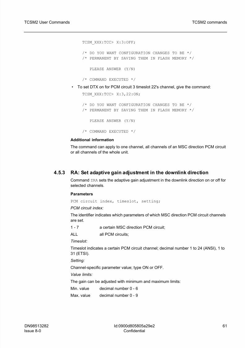
8/10/2019 TCSM COMMAND.pdf
http://slidepdf.com/reader/full/tcsm-commandpdf 61/125
DN98513282
Issue 8-0
61
TCSM2 User Commands TCSM2 commands
Id:0900d805805a29e2
Confidential
TCSM_XXX:TCC> X:3:OFF;
/* DO YOU WANT CONFIGURATION CHANGES TO BE */
/* PERMANENT BY SAVING THEM IN FLASH MEMORY */
PLEASE ANSWER (Y/N)
/* COMMAND EXECUTED */
• To set DTX on for PCM circuit 3 timeslot 22's channel, give the command:
TCSM_XXX:TCC> X:3,22:ON;
/* DO YOU WANT CONFIGURATION CHANGES TO BE */
/* PERMANENT BY SAVING THEM IN FLASH MEMORY */
PLEASE ANSWER (Y/N)
/* COMMAND EXECUTED */
Additional information
The command can apply to one channel, all channels of an MSC direction PCM circuit
or all channels of the whole unit.
4.5.3 RA: Set adaptive gain adjustment in the downlink direction
Command ZRA sets the adaptive gain adjustment in the downlink direction on or off for
selected channels.
Parameters
PCM circuit index, timeslot, setting;
PCM circuit index:
The identifier indicates which parameters of which MSC direction PCM circuit channels
are set.
1 - 7 a certain MSC direction PCM circuit;
ALL all PCM circuits;
Timeslot:
Timeslot indicates a certain PCM circuit channel; decimal number 1 to 24 (ANSI), 1 to
31 (ETSI).
Setting:
Channel-specific parameter value; type ON or OFF.
Value limits:
The gain can be adjusted with minimum and maximum limits:
Min. value decimal number 0 - 6
Max. value decimal number 0 - 9
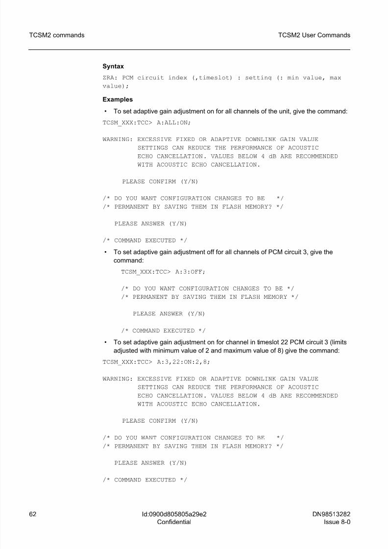
8/10/2019 TCSM COMMAND.pdf
http://slidepdf.com/reader/full/tcsm-commandpdf 62/125
62 DN98513282
Issue 8-0
TCSM2 User Commands
Id:0900d805805a29e2
Confidential
TCSM2 commands
Syntax
ZRA: PCM circuit index (,timeslot) : setting (: min value, max
value);
Examples
• To set adaptive gain adjustment on for all channels of the unit, give the command:
TCSM_XXX:TCC> A:ALL:ON;
WARNING: EXCESSIVE FIXED OR ADAPTIVE DOWNLINK GAIN VALUE
SETTINGS CAN REDUCE THE PERFORMANCE OF ACOUSTIC
ECHO CANCELLATION. VALUES BELOW 4 dB ARE RECOMMENDED
WITH ACOUSTIC ECHO CANCELLATION.
PLEASE CONFIRM (Y/N)
/* DO YOU WANT CONFIGURATION CHANGES TO BE */
/* PERMANENT BY SAVING THEM IN FLASH MEMORY? */
PLEASE ANSWER (Y/N)
/* COMMAND EXECUTED */
• To set adaptive gain adjustment off for all channels of PCM circuit 3, give the
command:
TCSM_XXX:TCC> A:3:OFF;
/* DO YOU WANT CONFIGURATION CHANGES TO BE *//* PERMANENT BY SAVING THEM IN FLASH MEMORY */
PLEASE ANSWER (Y/N)
/* COMMAND EXECUTED */
• To set adaptive gain adjustment on for channel in timeslot 22 PCM circuit 3 (limits
adjusted with minimum value of 2 and maximum value of 8) give the command:
TCSM_XXX:TCC> A:3,22:ON:2,8;
WARNING: EXCESSIVE FIXED OR ADAPTIVE DOWNLINK GAIN VALUE
SETTINGS CAN REDUCE THE PERFORMANCE OF ACOUSTIC
ECHO CANCELLATION. VALUES BELOW 4 dB ARE RECOMMENDED
WITH ACOUSTIC ECHO CANCELLATION.
PLEASE CONFIRM (Y/N)
/* DO YOU WANT CONFIGURATION CHANGES TO BE */
/* PERMANENT BY SAVING THEM IN FLASH MEMORY? */
PLEASE ANSWER (Y/N)
/* COMMAND EXECUTED */
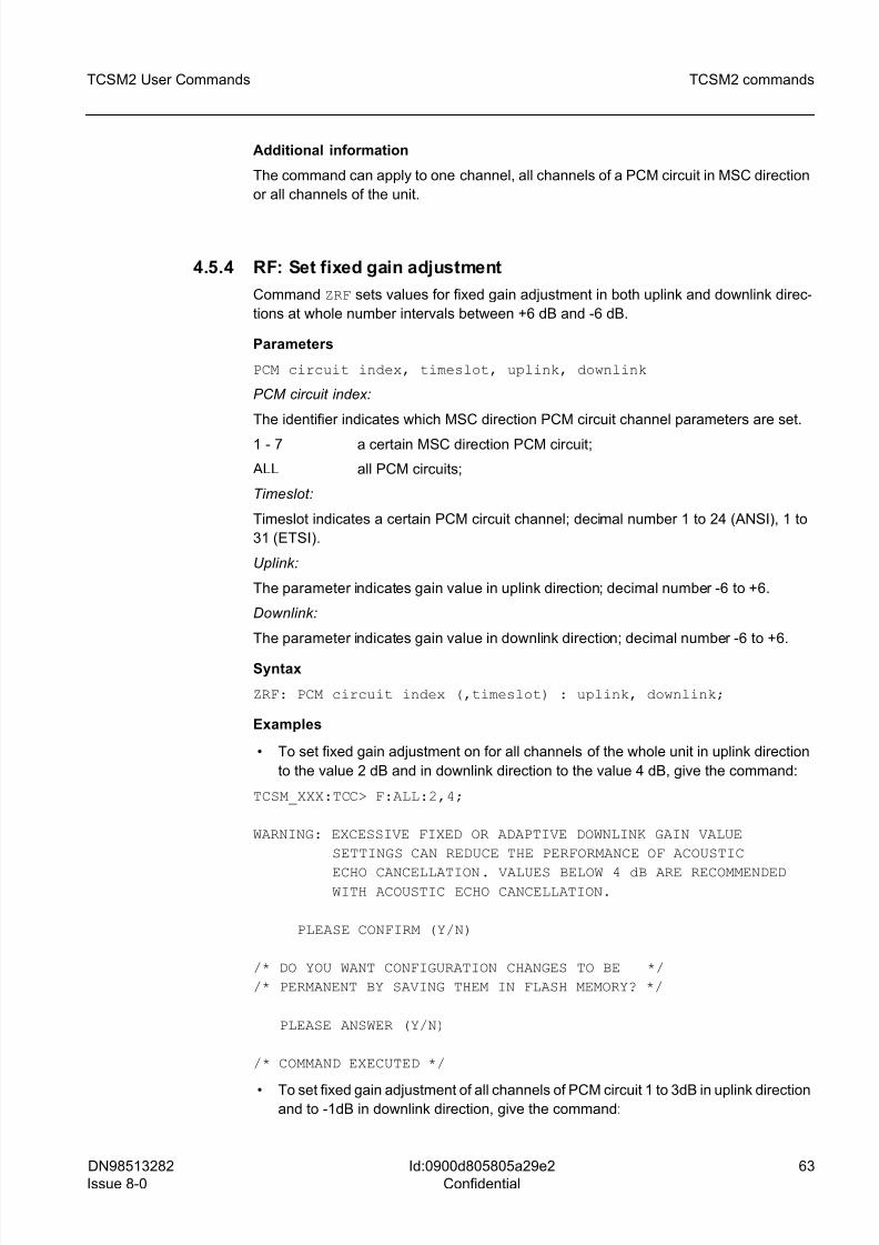
8/10/2019 TCSM COMMAND.pdf
http://slidepdf.com/reader/full/tcsm-commandpdf 63/125
DN98513282
Issue 8-0
63
TCSM2 User Commands TCSM2 commands
Id:0900d805805a29e2
Confidential
Additional information
The command can apply to one channel, all channels of a PCM circuit in MSC direction
or all channels of the unit.
4.5.4 RF: Set fixed gain adjustment
Command ZRF sets values for fixed gain adjustment in both uplink and downlink direc-
tions at whole number intervals between +6 dB and -6 dB.
Parameters
PCM circuit index, timeslot, uplink, downlink
PCM circuit index:
The identifier indicates which MSC direction PCM circuit channel parameters are set.
1 - 7 a certain MSC direction PCM circuit;
ALL all PCM circuits;
Timeslot:
Timeslot indicates a certain PCM circuit channel; decimal number 1 to 24 (ANSI), 1 to
31 (ETSI).
Uplink:
The parameter indicates gain value in uplink direction; decimal number -6 to +6.
Downlink:
The parameter indicates gain value in downlink direction; decimal number -6 to +6.
Syntax
ZRF: PCM circuit index (,timeslot) : uplink, downlink;
Examples
• To set fixed gain adjustment on for all channels of the whole unit in uplink direction
to the value 2 dB and in downlink direction to the value 4 dB, give the command:
TCSM_XXX:TCC> F:ALL:2,4;
WARNING: EXCESSIVE FIXED OR ADAPTIVE DOWNLINK GAIN VALUE
SETTINGS CAN REDUCE THE PERFORMANCE OF ACOUSTIC
ECHO CANCELLATION. VALUES BELOW 4 dB ARE RECOMMENDED WITH ACOUSTIC ECHO CANCELLATION.
PLEASE CONFIRM (Y/N)
/* DO YOU WANT CONFIGURATION CHANGES TO BE */
/* PERMANENT BY SAVING THEM IN FLASH MEMORY? */
PLEASE ANSWER (Y/N)
/* COMMAND EXECUTED */
• To set fixed gain adjustment of all channels of PCM circuit 1 to 3dB in uplink directionand to -1dB in downlink direction, give the command:
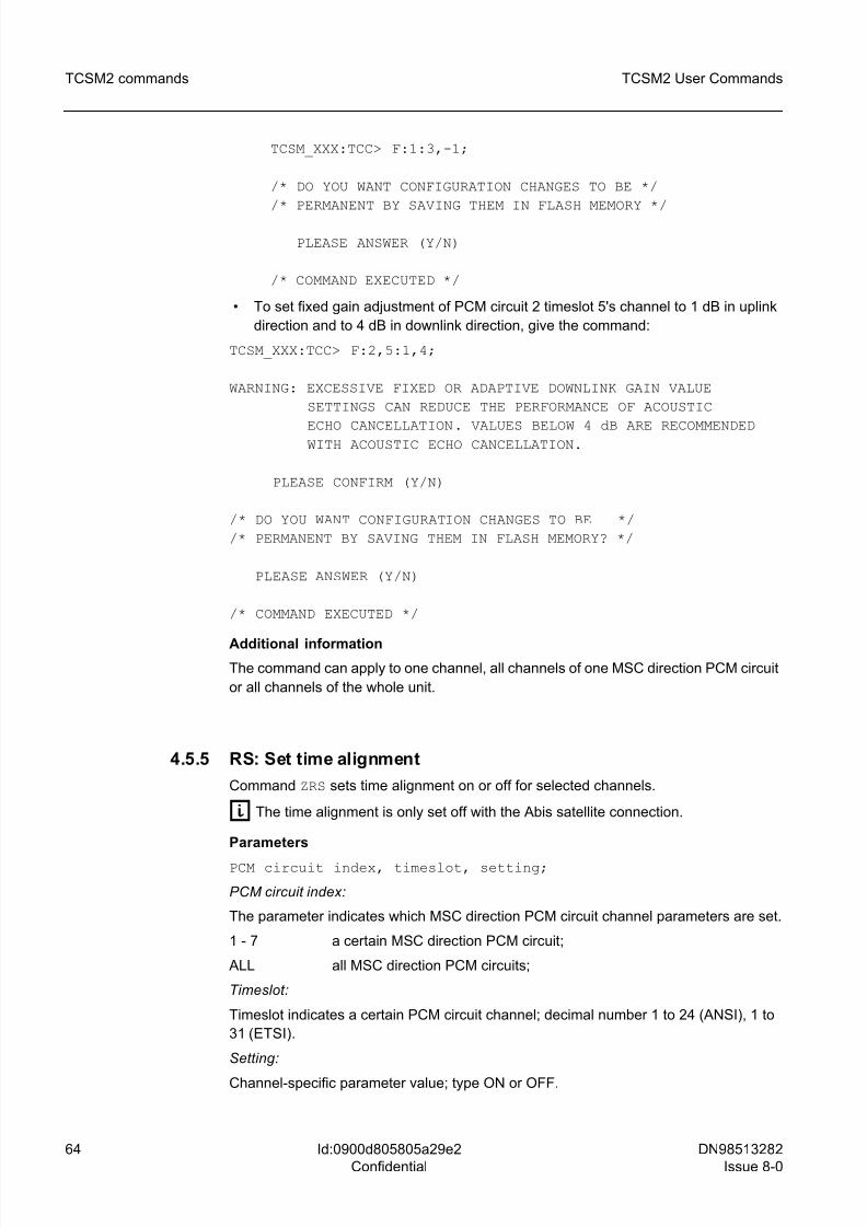
8/10/2019 TCSM COMMAND.pdf
http://slidepdf.com/reader/full/tcsm-commandpdf 64/125
64 DN98513282
Issue 8-0
TCSM2 User Commands
Id:0900d805805a29e2
Confidential
TCSM2 commands
TCSM_XXX:TCC> F:1:3,-1;
/* DO YOU WANT CONFIGURATION CHANGES TO BE */
/* PERMANENT BY SAVING THEM IN FLASH MEMORY */
PLEASE ANSWER (Y/N)
/* COMMAND EXECUTED */
• To set fixed gain adjustment of PCM circuit 2 timeslot 5's channel to 1 dB in uplink
direction and to 4 dB in downlink direction, give the command:
TCSM_XXX:TCC> F:2,5:1,4;
WARNING: EXCESSIVE FIXED OR ADAPTIVE DOWNLINK GAIN VALUE
SETTINGS CAN REDUCE THE PERFORMANCE OF ACOUSTIC
ECHO CANCELLATION. VALUES BELOW 4 dB ARE RECOMMENDED WITH ACOUSTIC ECHO CANCELLATION.
PLEASE CONFIRM (Y/N)
/* DO YOU WANT CONFIGURATION CHANGES TO BE */
/* PERMANENT BY SAVING THEM IN FLASH MEMORY? */
PLEASE ANSWER (Y/N)
/* COMMAND EXECUTED */
Additional information
The command can apply to one channel, all channels of one MSC direction PCM circuit
or all channels of the whole unit.
4.5.5 RS: Set time alignment
Command ZRS sets time alignment on or off for selected channels.
g The time alignment is only set off with the Abis satellite connection.
Parameters
PCM circuit index, timeslot, setting;
PCM circuit index:
The parameter indicates which MSC direction PCM circuit channel parameters are set.
1 - 7 a certain MSC direction PCM circuit;
ALL all MSC direction PCM circuits;
Timeslot:
Timeslot indicates a certain PCM circuit channel; decimal number 1 to 24 (ANSI), 1 to
31 (ETSI).
Setting:
Channel-specific parameter value; type ON or OFF.
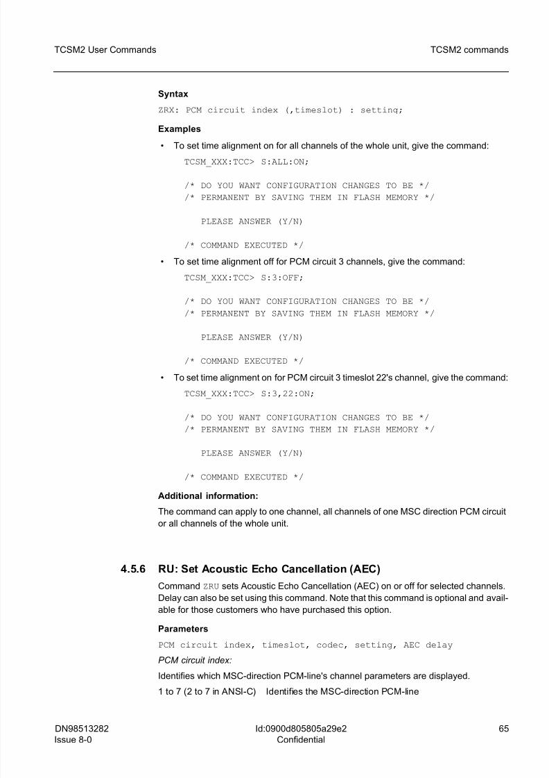
8/10/2019 TCSM COMMAND.pdf
http://slidepdf.com/reader/full/tcsm-commandpdf 65/125
DN98513282
Issue 8-0
65
TCSM2 User Commands TCSM2 commands
Id:0900d805805a29e2
Confidential
Syntax
ZRX: PCM circuit index (,timeslot) : setting;
Examples
• To set time alignment on for all channels of the whole unit, give the command:
TCSM_XXX:TCC> S:ALL:ON;
/* DO YOU WANT CONFIGURATION CHANGES TO BE */
/* PERMANENT BY SAVING THEM IN FLASH MEMORY */
PLEASE ANSWER (Y/N)
/* COMMAND EXECUTED */
• To set time alignment off for PCM circuit 3 channels, give the command:
TCSM_XXX:TCC> S:3:OFF;
/* DO YOU WANT CONFIGURATION CHANGES TO BE */
/* PERMANENT BY SAVING THEM IN FLASH MEMORY */
PLEASE ANSWER (Y/N)
/* COMMAND EXECUTED */
• To set time alignment on for PCM circuit 3 timeslot 22's channel, give the command:
TCSM_XXX:TCC> S:3,22:ON;
/* DO YOU WANT CONFIGURATION CHANGES TO BE */
/* PERMANENT BY SAVING THEM IN FLASH MEMORY */
PLEASE ANSWER (Y/N)
/* COMMAND EXECUTED */
Additional information:
The command can apply to one channel, all channels of one MSC direction PCM circuit
or all channels of the whole unit.
4.5.6 RU: Set Acoustic Echo Cancellation (AEC)
Command ZRU sets Acoustic Echo Cancellation (AEC) on or off for selected channels.
Delay can also be set using this command. Note that this command is optional and avail-
able for those customers who have purchased this option.
Parameters
PCM circuit index, timeslot, codec, setting, AEC delay
PCM circuit index:
Identifies which MSC-direction PCM-line's channel parameters are displayed.
1 to 7 (2 to 7 in ANSI-C) Identifies the MSC-direction PCM-line
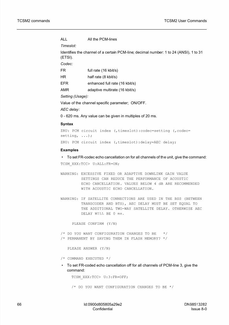
8/10/2019 TCSM COMMAND.pdf
http://slidepdf.com/reader/full/tcsm-commandpdf 66/125
66 DN98513282
Issue 8-0
TCSM2 User Commands
Id:0900d805805a29e2
Confidential
TCSM2 commands
ALL All the PCM-lines
Timeslot:
Identifies the channel of a certain PCM-line; decimal number: 1 to 24 (ANSI), 1 to 31
(ETSI).
Codec:
FR full rate (16 kbit/s)
HR half rate (8 kbit/s)
EFR enhanced full rate (16 kbit/s)
AMR adaptive multirate (16 kbit/s)
Setting (Usage):
Value of the channel specific parameter; ON/OFF.
AEC delay:
0 - 620 ms. Any value can be given in multiples of 20 ms.
Syntax
ZRU: PCM circuit index (,timeslot):codec=setting (,codec=
setting, ...);
ZRU: PCM circuit index (,timeslot):delay=AEC delay;
Examples
• To set FR-codec echo cancellation on for all channels of the unit, give the command:
TCSM_XXX:TCC> U:ALL:FR=ON;
WARNING: EXCESSIVE FIXED OR ADAPTIVE DOWNLINK GAIN VALUE
SETTINGS CAN REDUCE THE PERFORMANCE OF ACOUSTIC
ECHO CANCELLATION. VALUES BELOW 4 dB ARE RECOMMENDED
WITH ACOUSTIC ECHO CANCELLATION.
WARNING: IF SATELLITE CONNECTIONS ARE USED IN THE BSS (BETWEEN
TRANSCODER AND BTS), AEC DELAY MUST BE SET EQUAL TO
THE ADDITIONAL TWO-WAY SATELLITE DELAY. OTHERWISE AEC
DELAY WILL BE 0 ms.
PLEASE CONFIRM (Y/N)
/* DO YOU WANT CONFIGURATION CHANGES TO BE */
/* PERMANENT BY SAVING THEM IN FLASH MEMORY? */
PLEASE ANSWER (Y/N)
/* COMMAND EXECUTED */
• To set FR-coded echo cancellation off for all channels of PCM-line 3, give the
command:
TCSM_XXX:TCC> U:3:FR=OFF;
/* DO YOU WANT CONFIGURATION CHANGES TO BE */
8/10/2019 TCSM COMMAND.pdf
http://slidepdf.com/reader/full/tcsm-commandpdf 67/125
DN98513282
Issue 8-0
67
TCSM2 User Commands TCSM2 commands
Id:0900d805805a29e2
Confidential
/* PERMANENT BY SAVING THEM IN FLASH MEMORY */
PLEASE ANSWER (Y/N)
/* COMMAND EXECUTED */
• To set HR-codec echo cancellation on for the channel of timeslot 22 of PCM-line 3,
give the command:
TCSM_XXX:TCC> U:3,22:HR=ON;
WARNING: EXCESSIVE FIXED OR ADAPTIVE DOWNLINK GAIN VALUE
SETTINGS CAN REDUCE THE PERFORMANCE OF ACOUSTIC
ECHO CANCELLATION. VALUES BELOW 4 dB ARE RECOMMENDED
WITH ACOUSTIC ECHO CANCELLATION.
WARNING: IF SATELLITE CONNECTIONS ARE USED IN THE BSS (BETWEEN TRANSCODER AND BTS), AEC DELAY MUST BE SET EQUAL TO
THE ADDITIONAL TWO-WAY SATELLITE DELAY. OTHERWISE AEC
DELAY WILL BE 0 ms.
PLEASE CONFIRM (Y/N)
/* DO YOU WANT CONFIGURATION CHANGES TO BE */
/* PERMANENT BY SAVING THEM IN FLASH MEMORY? */
PLEASE ANSWER (Y/N)
/* COMMAND EXECUTED */
• To set acoustic echo cancellation (for all codecs) on for all the channels of the whole
unit, give the command:
TCSM_XXX:TCC> U:ALL:FR=ON,HR=ON,EFR=ON;
WARNING: EXCESSIVE FIXED OR ADAPTIVE DOWNLINK GAIN VALUE
SETTINGS CAN REDUCE THE PERFORMANCE OF ACOUSTIC
ECHO CANCELLATION. VALUES BELOW 4 dB ARE RECOMMENDED
WITH ACOUSTIC ECHO CANCELLATION.
WARNING: IF SATELLITE CONNECTIONS ARE USED IN THE BSS (BETWEEN TRANSCODER AND BTS), AEC DELAY MUST BE SET EQUAL TO
THE ADDITIONAL TWO-WAY SATELLITE DELAY. OTHERWISE AEC
DELAY WILL BE 0 ms.
PLEASE CONFIRM (Y/N)
/* DO YOU WANT CONFIGURATION CHANGES TO BE */
/* PERMANENT BY SAVING THEM IN FLASH MEMORY? */
PLEASE ANSWER (Y/N)
/* COMMAND EXECUTED */
8/10/2019 TCSM COMMAND.pdf
http://slidepdf.com/reader/full/tcsm-commandpdf 68/125
8/10/2019 TCSM COMMAND.pdf
http://slidepdf.com/reader/full/tcsm-commandpdf 69/125
DN98513282
Issue 8-0
69
TCSM2 User Commands TCSM2 commands
Id:0900d805805a29e2
Confidential
Codec:
FR full rate (16 kbit/s);
HR half rate (8 kbit/s)
EFR enhanced full rate (16 kbit/s);
Setting:
Value of the channel specific parameter; ON/OFF.
0 - 620. Any value can be given in multiples of 20 ms.
Syntax
ZRN: PCM circuit index (,timeslot):codec=setting (,codec=
setting, ...);
Examples
• To set FR-codec tandem free operation on for all channels of the unit, give thecommand:
TCSM_XXX:TCC> N:ALL:FR=ON;
PLEASE CONFIRM (Y/N)
/* DO YOU WANT CONFIGURATION CHANGES TO BE */
/* PERMANENT BY SAVING THEM IN FLASH MEMORY? */
PLEASE ANSWER (Y/N)
/* COMMAND EXECUTED */ • To set FR-coded tandem free operation off for all channels of PCM-line 3, give the
command:
TCSM_XXX:TCC> N:3:FR=OFF;
/* DO YOU WANT CONFIGURATION CHANGES TO BE */
/* PERMANENT BY SAVING THEM IN FLASH MEMORY */
PLEASE ANSWER (Y/N)
/* COMMAND EXECUTED */
• To set HR-codec tandem free operation on for the channel of timeslot 22 of PCM-
line 3, give the command:
TCSM_XXX:TCC> N:3,22:HR=ON;
PLEASE CONFIRM (Y/N)
/* DO YOU WANT CONFIGURATION CHANGES TO BE */
/* PERMANENT BY SAVING THEM IN FLASH MEMORY? */
PLEASE ANSWER (Y/N)
/* COMMAND EXECUTED */
8/10/2019 TCSM COMMAND.pdf
http://slidepdf.com/reader/full/tcsm-commandpdf 70/125
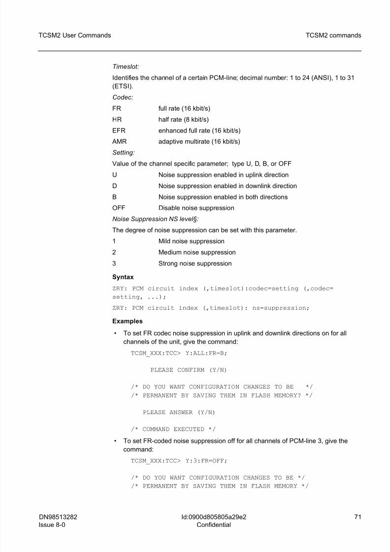
8/10/2019 TCSM COMMAND.pdf
http://slidepdf.com/reader/full/tcsm-commandpdf 71/125
DN98513282
Issue 8-0
71
TCSM2 User Commands TCSM2 commands
Id:0900d805805a29e2
Confidential
Timeslot:
Identifies the channel of a certain PCM-line; decimal number: 1 to 24 (ANSI), 1 to 31
(ETSI).
Codec:
FR full rate (16 kbit/s)
HR half rate (8 kbit/s)
EFR enhanced full rate (16 kbit/s)
AMR adaptive multirate (16 kbit/s)
Setting:
Value of the channel specific parameter; type U, D, B, or OFF
U Noise suppression enabled in uplink direction
D Noise suppression enabled in downlink direction
B Noise suppression enabled in both directions
OFF Disable noise suppression
Noise Suppression NS level§:
The degree of noise suppression can be set with this parameter.
1 Mild noise suppression
2 Medium noise suppression
3 Strong noise suppression
Syntax
ZRY: PCM circuit index (,timeslot):codec=setting (,codec=setting, ...);
ZRY: PCM circuit index (,timeslot): ns=suppression;
Examples
• To set FR codec noise suppression in uplink and downlink directions on for all
channels of the unit, give the command:
TCSM_XXX:TCC> Y:ALL:FR=B;
PLEASE CONFIRM (Y/N)
/* DO YOU WANT CONFIGURATION CHANGES TO BE *//* PERMANENT BY SAVING THEM IN FLASH MEMORY? */
PLEASE ANSWER (Y/N)
/* COMMAND EXECUTED */
• To set FR-coded noise suppression off for all channels of PCM-line 3, give the
command:
TCSM_XXX:TCC> Y:3:FR=OFF;
/* DO YOU WANT CONFIGURATION CHANGES TO BE */
/* PERMANENT BY SAVING THEM IN FLASH MEMORY */
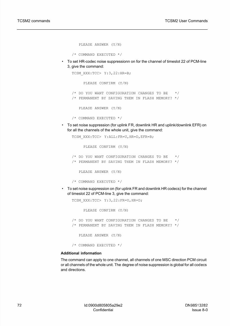
8/10/2019 TCSM COMMAND.pdf
http://slidepdf.com/reader/full/tcsm-commandpdf 72/125
72 DN98513282
Issue 8-0
TCSM2 User Commands
Id:0900d805805a29e2
Confidential
TCSM2 commands
PLEASE ANSWER (Y/N)
/* COMMAND EXECUTED */
• To set HR-codec noise suppressionn on for the channel of timeslot 22 of PCM-line
3, give the command:
TCSM_XXX:TCC> Y:3,22:HR=B;
PLEASE CONFIRM (Y/N)
/* DO YOU WANT CONFIGURATION CHANGES TO BE */
/* PERMANENT BY SAVING THEM IN FLASH MEMORY? */
PLEASE ANSWER (Y/N)
/* COMMAND EXECUTED */
• To set noise suppression (for uplink FR, downlink HR and uplink/downlink EFR) on
for all the channels of the whole unit, give the command:
TCSM_XXX:TCC> Y:ALL:FR=U,HR=D,EFR=B;
PLEASE CONFIRM (Y/N)
/* DO YOU WANT CONFIGURATION CHANGES TO BE */
/* PERMANENT BY SAVING THEM IN FLASH MEMORY? */
PLEASE ANSWER (Y/N)
/* COMMAND EXECUTED */
• To set noise suppression on (for uplink FR and downlink HR codecs) for the channel
of timeslot 22 of PCM-line 3, give the command:
TCSM_XXX:TCC> Y:3,22:FR=U,HR=D;
PLEASE CONFIRM (Y/N)
/* DO YOU WANT CONFIGURATION CHANGES TO BE */
/* PERMANENT BY SAVING THEM IN FLASH MEMORY? */
PLEASE ANSWER (Y/N)
/* COMMAND EXECUTED */
Additional information
The command can apply to one channel, all channels of one MSC direction PCM circuit
or all channels of the whole unit. The degree of noise suppression is global for all codecs
and directions.
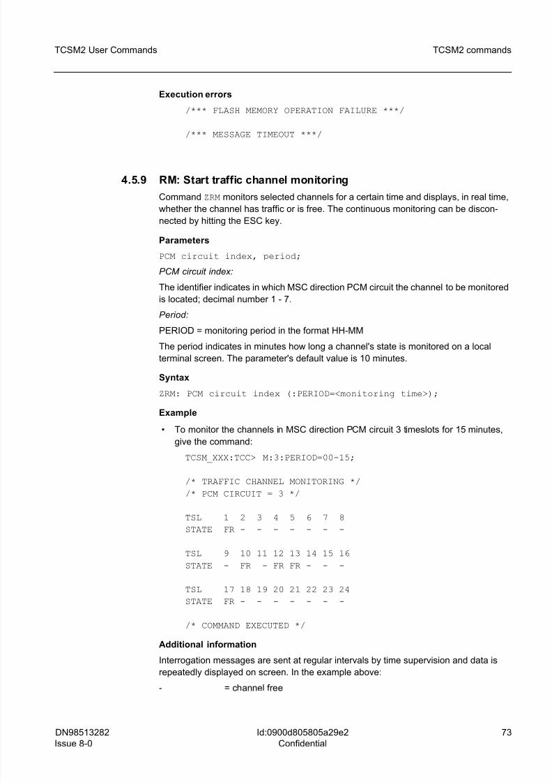
8/10/2019 TCSM COMMAND.pdf
http://slidepdf.com/reader/full/tcsm-commandpdf 73/125
DN98513282
Issue 8-0
73
TCSM2 User Commands TCSM2 commands
Id:0900d805805a29e2
Confidential
Execution errors
/*** FLASH MEMORY OPERATION FAILURE ***/
/*** MESSAGE TIMEOUT ***/
4.5.9 RM: Start traffic channel monitoring
Command ZRM monitors selected channels for a certain time and displays, in real time,
whether the channel has traffic or is free. The continuous monitoring can be discon-
nected by hitting the ESC key.
Parameters
PCM circuit index, period;
PCM circuit index:The identifier indicates in which MSC direction PCM circuit the channel to be monitored
is located; decimal number 1 - 7.
Period:
PERIOD = monitoring period in the format HH-MM
The period indicates in minutes how long a channel's state is monitored on a local
terminal screen. The parameter's default value is 10 minutes.
Syntax
ZRM: PCM circuit index (:PERIOD=<monitoring time>);
Example
• To monitor the channels in MSC direction PCM circuit 3 timeslots for 15 minutes,
give the command:
TCSM_XXX:TCC> M:3:PERIOD=00-15;
/* TRAFFIC CHANNEL MONITORING */
/* PCM CIRCUIT = 3 */
TSL 1 2 3 4 5 6 7 8
STATE FR - - - - - - -
TSL 9 10 11 12 13 14 15 16
STATE - FR - FR FR - - -
TSL 17 18 19 20 21 22 23 24
STATE FR - - - - - - -
/* COMMAND EXECUTED */
Additional information
Interrogation messages are sent at regular intervals by time supervision and data is
repeatedly displayed on screen. In the example above:
- = channel free
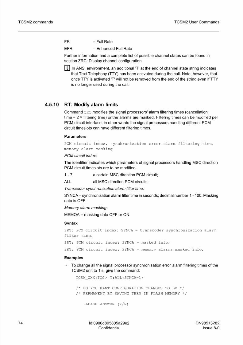
8/10/2019 TCSM COMMAND.pdf
http://slidepdf.com/reader/full/tcsm-commandpdf 74/125
74 DN98513282
Issue 8-0
TCSM2 User Commands
Id:0900d805805a29e2
Confidential
TCSM2 commands
FR = Full Rate
EFR = Enhanced Full Rate
Further information and a complete list of possible channel states can be found in
section ZRC: Display channel configuration.
g In ANSI environment, an additional 'T' at the end of channel state string indicates
that Text Telephony (TTY) has been activated during the call. Note, however, that
once TTY is activated 'T' will not be removed from the end of the string even if TTY
is no longer used during the call.
4.5.10 RT: Modify alarm limits
Command ZRT modifies the signal processors' alarm filtering times (cancellation
time = 2 × filtering time) or the alarms are masked. Filtering times can be modified per
PCM circuit interface, in other words the signal processors handling different PCM
circuit timeslots can have different filtering times.
Parameters
PCM circuit index, synchronization error alarm filtering time,
memory alarm masking
PCM circuit index:
The identifier indicates which parameters of signal processors handling MSC direction
PCM circuit timeslots are to be modified.
1 - 7 a certain MSC direction PCM circuit;
ALL all MSC direction PCM circuits;
Transcoder synchronization alarm filter time:
SYNCA = synchronization alarm filter time in seconds; decimal number 1 - 100. Masking
data is OFF.
Memory alarm masking:
MEMOA = masking data OFF or ON.
Syntax
ZRT: PCM circuit index: SYNCA = transcoder synchronization alarm
filter time;
ZRT: PCM circuit index: SYNCA = masked info;
ZRT: PCM circuit index: SYNCA = memory alarms masked info;
Examples
• To change all the signal processor synchronisation error alarm filtering times of the
TCSM2 unit to 1 s, give the command:
TCSM_XXX:TCC> T:ALL:SYNCA=1;
/* DO YOU WANT CONFIGURATION CHANGES TO BE */
/* PERMANENT BY SAVING THEM IN FLASH MEMORY */
PLEASE ANSWER (Y/N)
8/10/2019 TCSM COMMAND.pdf
http://slidepdf.com/reader/full/tcsm-commandpdf 75/125
DN98513282
Issue 8-0
75
TCSM2 User Commands TCSM2 commands
Id:0900d805805a29e2
Confidential
/* COMMAND EXECUTED */
• To mask memory alarm of signal processors handling MSC direction PCM circuit 3,
give the command:TCSM_XXX:TCC> T:3:MEMOA=OFF;
/* DO YOU WANT CONFIGURATION CHANGES TO BE */
/* PERMANENT BY SAVING THEM IN FLASH MEMORY */
PLEASE ANSWER (Y/N)
/* COMMAND EXECUTED */
• To remove memory alarm masking in all signal processors of the TCSM2 unit, give
the command:
TCSM_XXX:TCC> T:ALL:MEMOA=ON;
/* DO YOU WANT CONFIGURATION CHANGES TO BE */
/* PERMANENT BY SAVING THEM IN FLASH MEMORY */
PLEASE ANSWER (Y/N)
/* COMMAND EXECUTED */
4.5.11 RO: Display alarm limitsCommand ZRO displays filtering and cancellation times of signal processor alarms.
Parameters
PCM circuit index:
The PCM circuit index indicates which PCM circuit parameters are to be displayed.
1 - 7 one PCM circuit in the MSC direction;
ALL all MSC direction PCM circuits;
Syntax
ZRO: PCM circuit index;
Examples
• To display alarm filtering and cancellation times of signal processors handling
timeslots of MSC direction PCM circuit 2 connected to the ET2A/ET2E, give the
command:
TCSM_XXX:TCC> O:2;
/* TRANSCODER ALARM FILTERING AND */
/* CANCELLING TIMES */
PCM SYNCA SYNCC MEMOA
LINE (S) (S) (S)
8/10/2019 TCSM COMMAND.pdf
http://slidepdf.com/reader/full/tcsm-commandpdf 76/125
76 DN98513282
Issue 8-0
TCSM2 User Commands
Id:0900d805805a29e2
Confidential
TCSM2 commands
PCM-2 1 2 MASKED
/* COMMAND EXECUTED */
• To display alarm filtering and cancellation times of signal processors of all MSC
direction PCM circuit timeslots, give the command:
TCSM_XXX:TCC> O:ALL;
/* TRANSCODER ALARM FILTERING */
/* AND CANCELLING TIMES */
PCM SYNCA SYNCC MEMOA
LINE (S) (S)
PCM-1 1 2 ALLOWEDPCM-2 MASKED - ALLOWED
PCM-3 1 2 ALLOWED
PCM-4 MASKED - MASKED
/* COMMAND EXECUTED */
4.5.12 RR: Set transcoder PCM types
Command ZRR is used to set various transcoder PCM types. It sets the number and type
of PCM circuits, the number of plug-in units, the number of synchronisation inputs and
the type of the Group Switch. Group Switch type, MSC direction PCM circuit index and
PCM type are given as parameters.
Parameters
Group Switch, MSC direction PCM circuit index, PCM type
Group Switch type in the BSC:
GSW Group Switch (64 kbit/s)
GSWB Bit Group Switch (8 kbit/s)
PCM circuit index:
The circuit index indicates which MSC direction PCM circuits are to be set; decimal
number 1 to 7 (2 to 7 for the TCSM2A-C).
PCM types:
A = FR & EFR & D144 Available when the BSC is provided with the Group Switch
(GSW) or Bit Group Switch (GSWB)
B = HR Available when the BSC is provided with the Bit Group Switch (GSWB)
C = EFR & FR & HR & D144 Available when the BSC is provided with the Bit Group
Switch (GSWB)
D = EFR & FR & HR & HS2 & D144 Available when the BSC is provided with the Bit
Group Switch (GSWB)
8/10/2019 TCSM COMMAND.pdf
http://slidepdf.com/reader/full/tcsm-commandpdf 77/125
DN98513282
Issue 8-0
77
TCSM2 User Commands TCSM2 commands
Id:0900d805805a29e2
Confidential
E = EFR & FR & HR & HS4 & D144 Available when the BSC is provided with the Bit
Group Switch (GSWB)
F = AMR Available when the BSC is provided with the Bit Group Switch (GSWB)
where:
FR = Full Rate
EFR = Enhanced Full Rate
HR = Half Rate
D144 = 14.4 kbit/s GSM Data Service
HS2 = High Speed Circuit Switched Data (HSCSD) (2 × FR, 32 kbit/s)
HS4 = High Speed Circuit Switched Data (HSCSD) (4 × FR, 64 kbit/s)
AMR Adaptive Multirate
Syntax
ZRR: group switch: PCM index = PCM type(, PCM index= PCM
type,...);
Examples
• To set MSC direction PCM circuits 1-7 into Half Rate mode when the 8 kbit/s Bit
Group Switch (in the BSC) is in use, give the command:
TCSM_XXX:TCC> R:GSWB:1=B,2=B,3=B,4=B,5=B,6=B,7=B;
/* DO YOU WANT CONFIGURATION CHANGES TO BE */
/* PERMANENT BY SAVING THEM IN FLASH MEMORY */
PLEASE ANSWER (Y/N)
/* COMMAND EXECUTED */
• To set MSC direction PCM circuits 1-3 into full rate mode when the 8 kbit/s Bit Group
Switch (in the BSC) is in use, give the command:
TCSM_XXX:TCC> R:GSWB:1=A,2=A,3=A;
/* DO YOU WANT CONFIGURATION CHANGES TO BE */
/* PERMANENT BY SAVING THEM IN FLASH MEMORY */
PLEASE ANSWER (Y/N)
/* COMMAND EXECUTED */
4.5.13 RD: Display transcoder PCM types
Command ZRD displays the selected transcoder PCM types.
Syntax
ZRD;
8/10/2019 TCSM COMMAND.pdf
http://slidepdf.com/reader/full/tcsm-commandpdf 78/125
78 DN98513282
Issue 8-0
TCSM2 User Commands
Id:0900d805805a29e2
Confidential
TCSM2 commands
Example
• To display transcoder PCM types, give the command:
TCSM_XXX:TCC> D;
/* TRANSCODER PCM TYPES */
GROUP SWITCH GSWB
PCM TYPES
PCM-1 FR & EFR & D144
PCM-2 FR & EFR & D144
PCM-3 FR & EFR & D144
PCM-4 NU
PCM-5 NUPCM-6 NU
PCM-7 NU
/* COMMAND EXECUTED */
g NU = not used
4.6 E: Exchange Terminal supervision commands
Command group ZE? in the main menu (TCSM_XXX:LUC>) displays the following sub-
menu with exchange terminal supervision commands:
EXCHANGE TERMINAL SUPERVISION COMMANDS
? ..... MENU / HELP
M ..... MODIFY ET PARAMETERS
O ..... DISPLAY ET PARAMETERS
A ..... MODIFY ALARM LIMITS
P ..... DISPLAY ALARM LIMITS
S ..... MODIFY STATISTICS COUNTERS LIMITS
L ..... DISPLAY STATISTICS COUNTERS LIMITS
U ..... MODIFY SLIP LIMITS
R ..... DISPLAY SLIP LIMITSC ..... MODIFY FUNCTIONAL MODES
I ..... DISPLAY FUNCTIONAL MODES
Z ..... RETURN TO MAIN LEVEL
TCSM_XXX:ESC>
The following sections describe the exchange terminal supervision commands
(TCSM_XXX:ESC>) available in more detail, their use, parameters, syntax. Command
examples are also given.
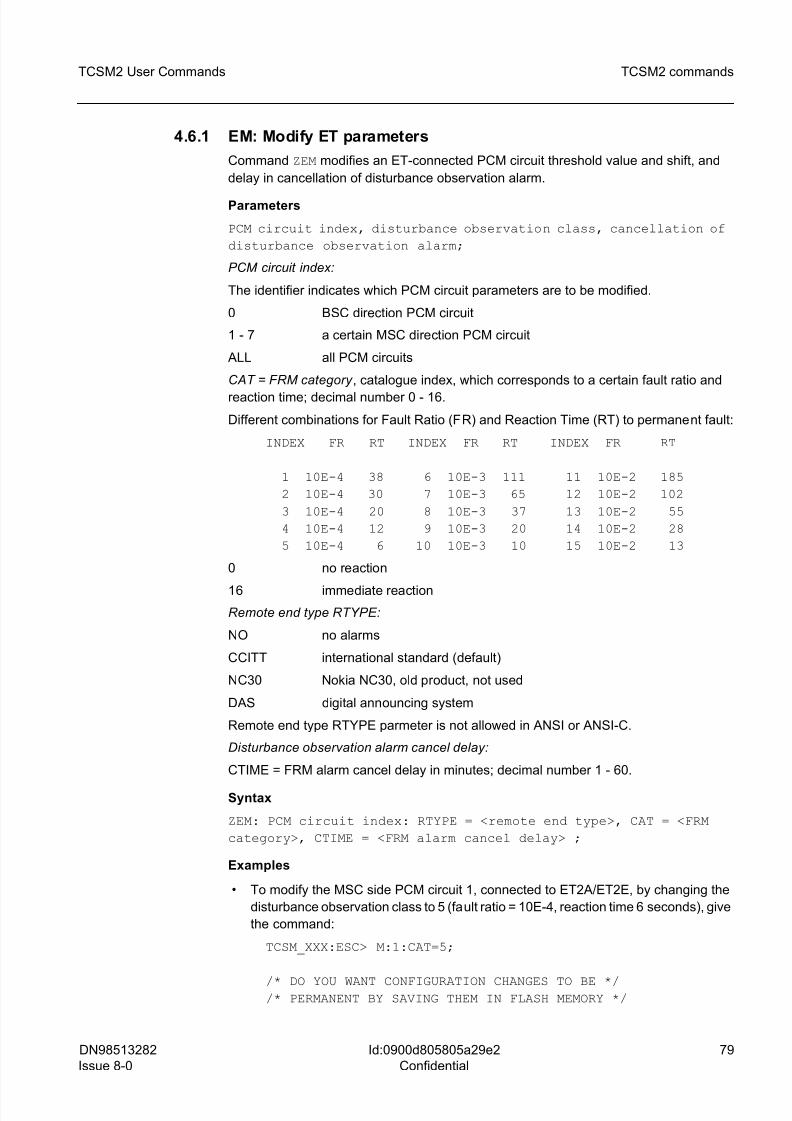
8/10/2019 TCSM COMMAND.pdf
http://slidepdf.com/reader/full/tcsm-commandpdf 79/125
DN98513282
Issue 8-0
79
TCSM2 User Commands TCSM2 commands
Id:0900d805805a29e2
Confidential
4.6.1 EM: Modify ET parameters
Command ZEM modifies an ET-connected PCM circuit threshold value and shift, and
delay in cancellation of disturbance observation alarm.
Parameters
PCM circuit index, disturbance observation class, cancellation of
disturbance observation alarm;
PCM circuit index:
The identifier indicates which PCM circuit parameters are to be modified.
0 BSC direction PCM circuit
1 - 7 a certain MSC direction PCM circuit
ALL all PCM circuits
CAT = FRM category , catalogue index, which corresponds to a certain fault ratio and
reaction time; decimal number 0 - 16.
Different combinations for Fault Ratio (FR) and Reaction Time (RT) to permanent fault:
INDEX FR RT INDEX FR RT INDEX FR RT
1 10E-4 38 6 10E-3 111 11 10E-2 185
2 10E-4 30 7 10E-3 65 12 10E-2 102
3 10E-4 20 8 10E-3 37 13 10E-2 55
4 10E-4 12 9 10E-3 20 14 10E-2 28
5 10E-4 6 10 10E-3 10 15 10E-2 13
0 no reaction
16 immediate reaction
Remote end type RTYPE:
NO no alarms
CCITT international standard (default)
NC30 Nokia NC30, old product, not used
DAS digital announcing system
Remote end type RTYPE parmeter is not allowed in ANSI or ANSI-C.
Disturbance observation alarm cancel delay:
CTIME = FRM alarm cancel delay in minutes; decimal number 1 - 60.
Syntax
ZEM: PCM circuit index: RTYPE = <remote end type>, CAT = <FRM
category>, CTIME = <FRM alarm cancel delay> ;
Examples
• To modify the MSC side PCM circuit 1, connected to ET2A/ET2E, by changing the
disturbance observation class to 5 (fault ratio = 10E-4, reaction time 6 seconds), give
the command:
TCSM_XXX:ESC> M:1:CAT=5;
/* DO YOU WANT CONFIGURATION CHANGES TO BE *//* PERMANENT BY SAVING THEM IN FLASH MEMORY */
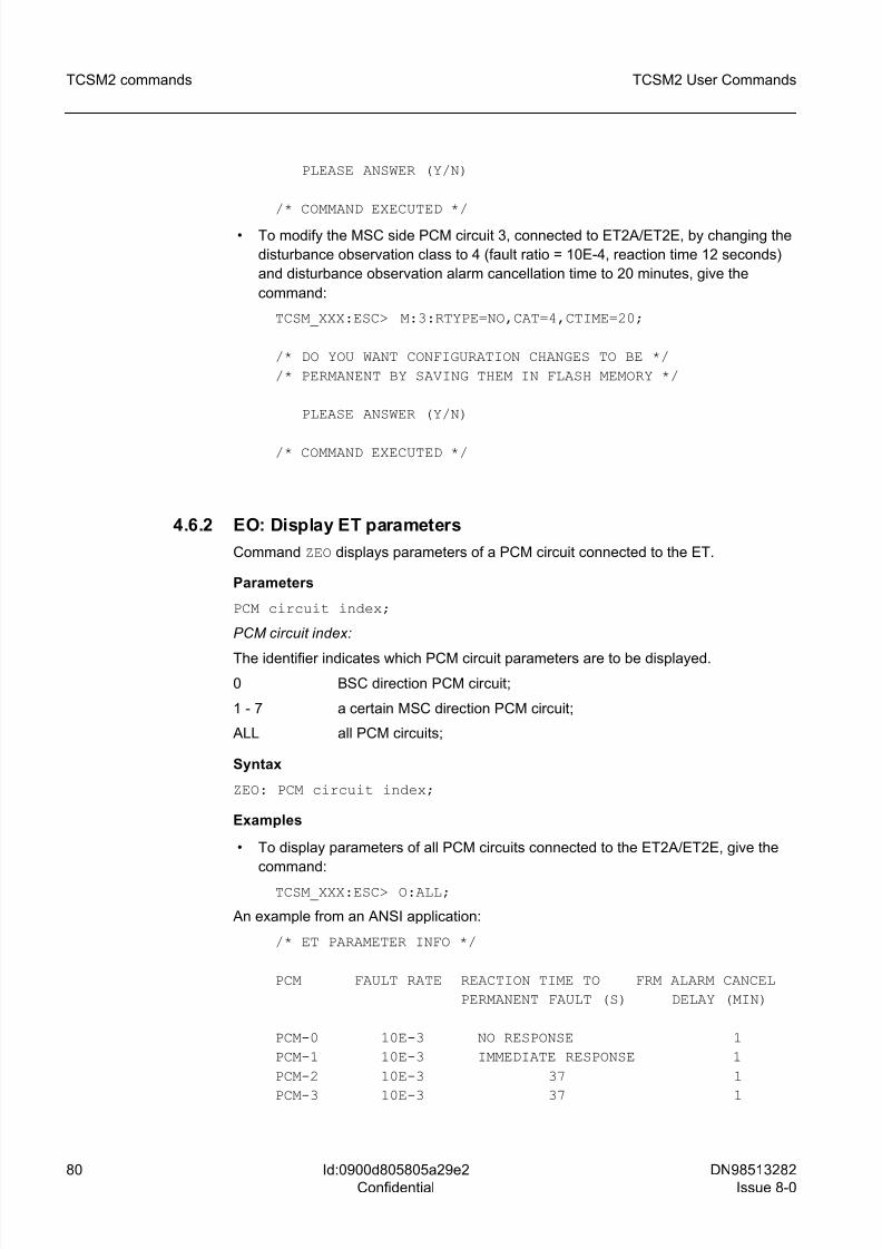
8/10/2019 TCSM COMMAND.pdf
http://slidepdf.com/reader/full/tcsm-commandpdf 80/125
80 DN98513282
Issue 8-0
TCSM2 User Commands
Id:0900d805805a29e2
Confidential
TCSM2 commands
PLEASE ANSWER (Y/N)
/* COMMAND EXECUTED */
• To modify the MSC side PCM circuit 3, connected to ET2A/ET2E, by changing the
disturbance observation class to 4 (fault ratio = 10E-4, reaction time 12 seconds)
and disturbance observation alarm cancellation time to 20 minutes, give the
command:
TCSM_XXX:ESC> M:3:RTYPE=NO,CAT=4,CTIME=20;
/* DO YOU WANT CONFIGURATION CHANGES TO BE */
/* PERMANENT BY SAVING THEM IN FLASH MEMORY */
PLEASE ANSWER (Y/N)
/* COMMAND EXECUTED */
4.6.2 EO: Display ET parameters
Command ZEO displays parameters of a PCM circuit connected to the ET.
Parameters
PCM circuit index;
PCM circuit index:
The identifier indicates which PCM circuit parameters are to be displayed.
0 BSC direction PCM circuit;
1 - 7 a certain MSC direction PCM circuit;
ALL all PCM circuits;
Syntax
ZEO: PCM circuit index;
Examples
• To display parameters of all PCM circuits connected to the ET2A/ET2E, give the
command:
TCSM_XXX:ESC> O:ALL;
An example from an ANSI application:
/* ET PARAMETER INFO */
PCM FAULT RATE REACTION TIME TO FRM ALARM CANCEL
PERMANENT FAULT (S) DELAY (MIN)
PCM-0 10E-3 NO RESPONSE 1
PCM-1 10E-3 IMMEDIATE RESPONSE 1
PCM-2 10E-3 37 1
PCM-3 10E-3 37 1
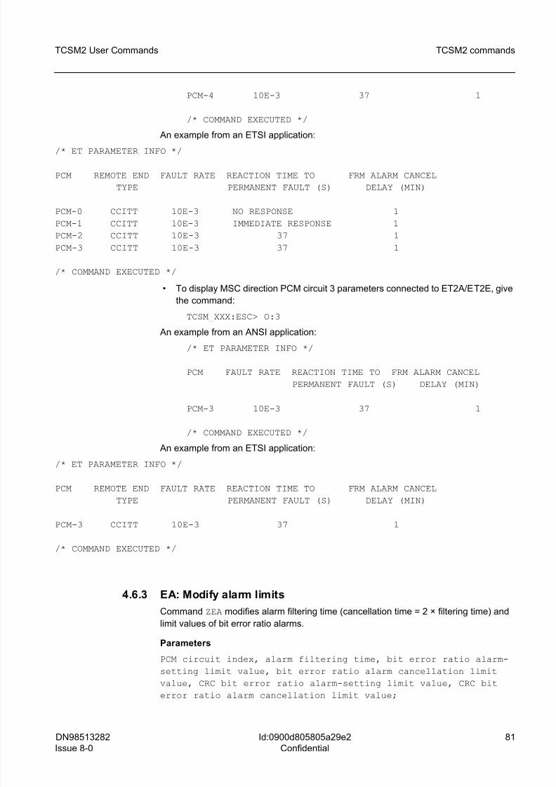
8/10/2019 TCSM COMMAND.pdf
http://slidepdf.com/reader/full/tcsm-commandpdf 81/125
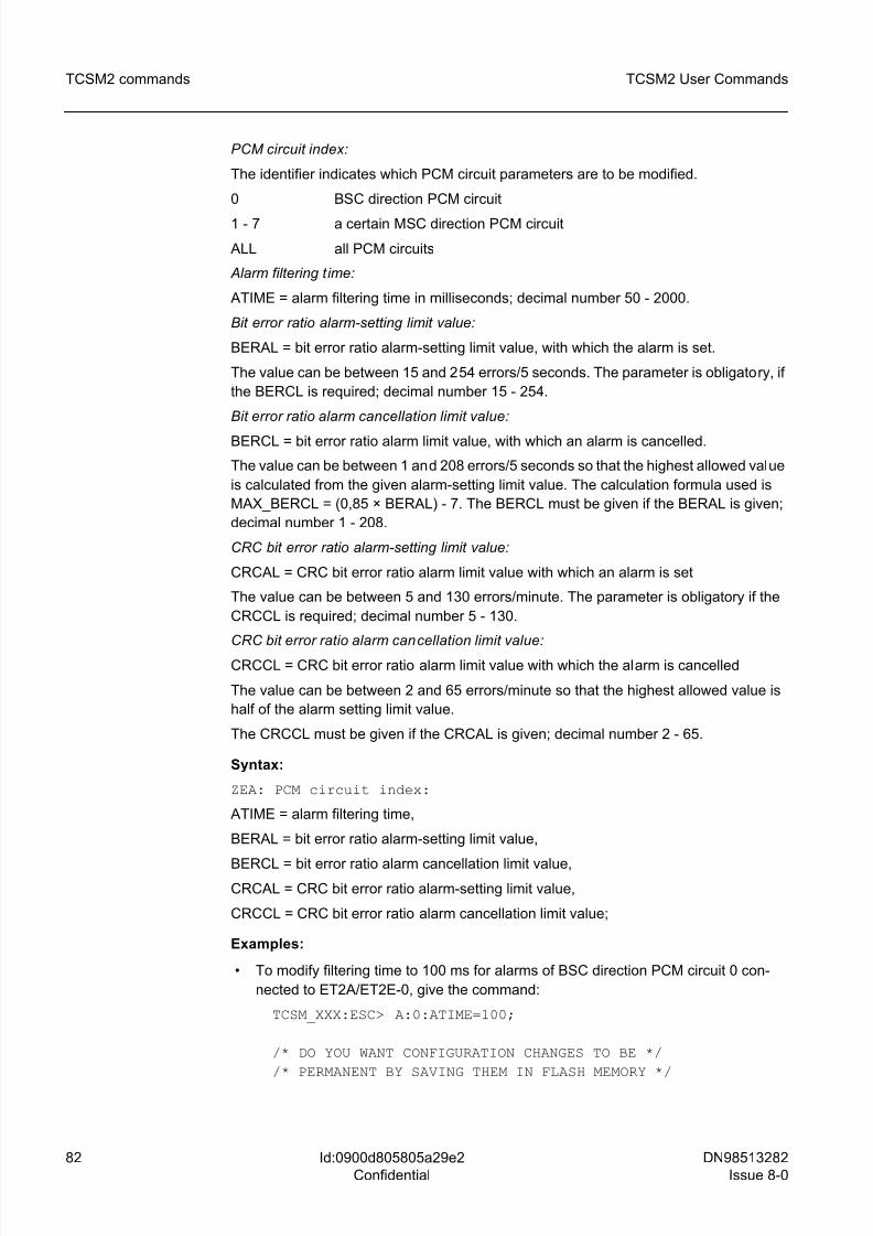
8/10/2019 TCSM COMMAND.pdf
http://slidepdf.com/reader/full/tcsm-commandpdf 82/125
82 DN98513282
Issue 8-0
TCSM2 User Commands
Id:0900d805805a29e2
Confidential
TCSM2 commands
PCM circuit index:
The identifier indicates which PCM circuit parameters are to be modified.
0 BSC direction PCM circuit
1 - 7 a certain MSC direction PCM circuit
ALL all PCM circuits
Alarm filtering t ime:
ATIME = alarm filtering time in milliseconds; decimal number 50 - 2000.
Bit error ratio alarm-setting limit value:
BERAL = bit error ratio alarm-setting limit value, with which the alarm is set.
The value can be between 15 and 254 errors/5 seconds. The parameter is obligatory, if
the BERCL is required; decimal number 15 - 254.
Bit error ratio alarm cancellation limit value:
BERCL = bit error ratio alarm limit value, with which an alarm is cancelled.
The value can be between 1 and 208 errors/5 seconds so that the highest allowed value
is calculated from the given alarm-setting limit value. The calculation formula used is
MAX_BERCL = (0,85 × BERAL) - 7. The BERCL must be given if the BERAL is given;
decimal number 1 - 208.
CRC bit error ratio alarm-setting limit value:
CRCAL = CRC bit error ratio alarm limit value with which an alarm is set
The value can be between 5 and 130 errors/minute. The parameter is obligatory if the
CRCCL is required; decimal number 5 - 130.
CRC bit error ratio alarm cancellation limit value:
CRCCL = CRC bit error ratio alarm limit value with which the alarm is cancelled
The value can be between 2 and 65 errors/minute so that the highest allowed value is
half of the alarm setting limit value.
The CRCCL must be given if the CRCAL is given; decimal number 2 - 65.
Syntax:
ZEA: PCM circuit index:
ATIME = alarm filtering time,
BERAL = bit error ratio alarm-setting limit value,
BERCL = bit error ratio alarm cancellation limit value,CRCAL = CRC bit error ratio alarm-setting limit value,
CRCCL = CRC bit error ratio alarm cancellation limit value;
Examples:
• To modify filtering time to 100 ms for alarms of BSC direction PCM circuit 0 con-
nected to ET2A/ET2E-0, give the command:
TCSM_XXX:ESC> A:0:ATIME=100;
/* DO YOU WANT CONFIGURATION CHANGES TO BE */
/* PERMANENT BY SAVING THEM IN FLASH MEMORY */
8/10/2019 TCSM COMMAND.pdf
http://slidepdf.com/reader/full/tcsm-commandpdf 83/125
DN98513282
Issue 8-0
83
TCSM2 User Commands TCSM2 commands
Id:0900d805805a29e2
Confidential
PLEASE ANSWER (Y/N)
/* COMMAND EXECUTED */
• To modify the MSC side PCM circuit 3, connected to ET2E/ET2A-1, by changing thesetting limit value to 150 errors/5 seconds and cancellation limit value to 100 errors/5
seconds for bit error ratio alarms, give the command:
TCSM_XXX:ESC> A:3:BERAL=150,BERCL=100;
/* DO YOU WANT CONFIGURATION CHANGES TO BE */
/* PERMANENT BY SAVING THEM IN FLASH MEMORY */
PLEASE ANSWER (Y/N)
/* COMMAND EXECUTED */
• To modify the MSC side PCM circuit 4, connected to ET2E/ET2A-2, by changing thealarm filtering time to 250 ms, CRC bit error ratio alarms limit value to 70 errors per
minute and cancellation limit value to 25 errors per minute, give the command:
TCSM_XXX:ESC> A:4:ATIME=250,CRCAL=70,CRCCL=25;
/* DO YOU WANT CONFIGURATION CHANGES TO BE */
/* PERMANENT BY SAVING THEM IN FLASH MEMORY */
PLEASE ANSWER (Y/N)
/* COMMAND EXECUTED */
4.6.4 EP: Display alarm limits
Command ZEP displays alarm filtering and cancellation times and bit error ratio alarm
limit values.
Parameters
PCM circuit index;
PCM circuit index:
The identifier indicates which PCM circuit parameters are to be displayed.
0 BSC direction PCM circuit
1 - 7 a certain MSC direction PCM circuit
ALL all PCM circuits
Syntax
ZEP: PCM circuit index;
Examples
• To display alarm limit values of MSC direction PCM circuit 2 connected to
ET2E/ET2A-1, give the command:
8/10/2019 TCSM COMMAND.pdf
http://slidepdf.com/reader/full/tcsm-commandpdf 84/125
84 DN98513282
Issue 8-0
TCSM2 User Commands
Id:0900d805805a29e2
Confidential
TCSM2 commands
TCSM_XXX:ESC> P:2;
/* PCM DEFINED ALARM VALUES */
PCM ATIME CTIME BERAL BERCL CRCAL CRCCL
TRUNK (MS) (MS) (ERR/5 S) (ERR/5 S) (ERR/MIN) (ERR/MIN)
PCM-2 100 200 80 40 63 31
/* COMMAND EXECUTED */
4.6.5 ES: Modify statistics counters limits
Command ZES modifies limit values of frame alignment signal errors and short distur-
bance statistics counters.
Parameters
PCM circuit index, frame alignment signal error limit values,
short disturbance limit values
PCM circuit index:
The identifier indicates which PCM circuit parameters are to be modified.
0 BSC direction PCM circuit
1 - 7 a certain MSC direction PCM circuit
ALL all PCM circuits
Frame alignment signal error limit values:
FLIM = frame alignment signal error statistics counters limit values in the format x1-x2-
x3
Three values are always given. The lowest acceptable is 2 and the highest 254 errors/5
s. Limit values are given in order of size (the lowest first), and the same value cannot be
given twice.
Short disturbance limit values:
DLIM = short disturbance statistics counters limit values are in the format x1-x2-x3-x4
Four values are always given. The lowest acceptable is 10 and the highest 9999 ms.
Limit values are given in order of size (the lowest first), and the same value cannot begiven twice.
Syntax
ZES: PCM circuit index: FLIM = <frame alignment signal error limit
values>, DLIM = <short disturbance limit values>;
Examples
• To modify to 10, 40 and 80 the limit values of MSC direction PCM circuit 2's frame
alignment signal error statistics counters connected to ET2E/ET2A-1, give the
command:
TCSM_XXX:ESC> S:2:FLIM=10-40-80;
8/10/2019 TCSM COMMAND.pdf
http://slidepdf.com/reader/full/tcsm-commandpdf 85/125
DN98513282
Issue 8-0
85
TCSM2 User Commands TCSM2 commands
Id:0900d805805a29e2
Confidential
/* DO YOU WANT CONFIGURATION CHANGES TO BE */
/* PERMANENT BY SAVING THEM IN FLASH MEMORY */
PLEASE ANSWER (Y/N)
/* COMMAND EXECUTED */
• To modify to 10, 50, 200 and 1000 the limit values of BSC direction PCM circuit 0's
short disturbance statistics counters connected to ET2E/ET2A-0, give the
command:
TCSM_XXX:ESC> S:0:DLIM=10-50-200-1000;
/* DO YOU WANT CONFIGURATION CHANGES TO BE */
/* PERMANENT BY SAVING THEM IN FLASH MEMORY */
PLEASE ANSWER (Y/N)
/* COMMAND EXECUTED */
4.6.6 EL: Display statistics counters limits
Command ZEL displays limit values of statistics counters of frame alignment signal
errors and short disturbances.
Parameters
PCM circuit index, statistics counter type;
PCM circuit index:
The identifier indicates which PCM circuit parameters are to be displayed.
0 BSC direction PCM circuit
1 - 7 a certain MSC direction PCM circuit
ALL all PCM circuits
Statistics counter type:
The type indicates which statistics counters' limit values are to be displayed:
FLIM frame alignment signal errors
DLIM short disturbances
Syntax
ZEL: PCM circuit index : statistics counter type;
Examples
• To display limit values of short disturbance statistics counters of all ETs, give the
command:
TCSM_XXX:ESC> L:ALL:DLIM;
/* PCM STATISTICS COUNTER */
/* DISTURBANCES */
8/10/2019 TCSM COMMAND.pdf
http://slidepdf.com/reader/full/tcsm-commandpdf 86/125
86 DN98513282
Issue 8-0
TCSM2 User Commands
Id:0900d805805a29e2
Confidential
TCSM2 commands
PCM COUNTER LIMITS (MS)
PCM-0 10-50 50-200 200-1000 1000-
PCM-1 10-50 50-200 200-1000 1000-
PCM-2 10-50 50-200 200-1000 1000-
PCM-3 10-50 50-200 200-1000 1000-
/* COMMAND EXECUTED */
• To display statistics counters' limit values of frame alignment signal errors of MSC
direction PCM circuit 3 connected to ET2E/ET2A-1, give the command:
TCSM_XXX:ESC> L:3:FLIM;
/* PCM STATISTICS COUNTER */
/* FRAME ALIGNMENT SIGNAL ERRORS */
PCM COUNTER LIMITS (ERRORS/5 SECONDS)
PCM-3 1-9 10-39 40-79 80-
/* COMMAND EXECUTED */
4.6.7 EU: Modify slip limits
Command ZEU modifies slip disturbance and alarm limits.
Parameters
PCM circuit index, slip disturbance onset threshold value, slip
alarm onset threshold value
PCM circuit index:
The identifier indicates which PCM circuit parameters are to be modified.
0 BSC direction PCM circuit
1 - 7 a certain MSC direction PCM circuit
ALL all PCM circuits
Slip disturbance onset threshold value:
SLIDL = slip disturbance limit value, with which the disturbance is set.
The value to be given can be between 1 and 23 slips/24 h; decimal number.
Slip alarm onset threshold value:
SLIAL = slip alarm onset threshold value with which the alarm is set.
The value to be given can be between 1 and 60 slips/h; decimal number.
Syntax
ZEU: PCM circuit index: SLIDL = <slip disturbance onset threshold
value>, SLIAL = <slip alarm onset threshold value>;
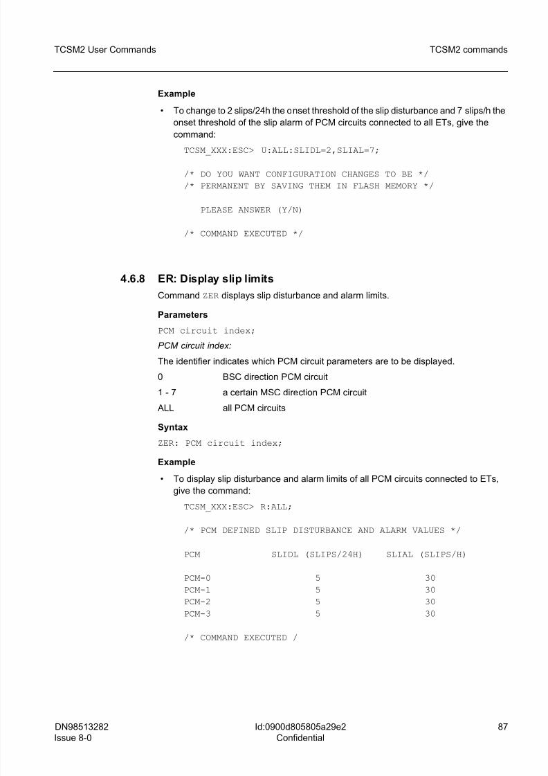
8/10/2019 TCSM COMMAND.pdf
http://slidepdf.com/reader/full/tcsm-commandpdf 87/125
DN98513282
Issue 8-0
87
TCSM2 User Commands TCSM2 commands
Id:0900d805805a29e2
Confidential
Example
• To change to 2 slips/24h the onset threshold of the slip disturbance and 7 slips/h the
onset threshold of the slip alarm of PCM circuits connected to all ETs, give the
command:TCSM_XXX:ESC> U:ALL:SLIDL=2,SLIAL=7;
/* DO YOU WANT CONFIGURATION CHANGES TO BE */
/* PERMANENT BY SAVING THEM IN FLASH MEMORY */
PLEASE ANSWER (Y/N)
/* COMMAND EXECUTED */
4.6.8 ER: Display slip limits
Command ZER displays slip disturbance and alarm limits.
Parameters
PCM circuit index;
PCM circuit index:
The identifier indicates which PCM circuit parameters are to be displayed.
0 BSC direction PCM circuit
1 - 7 a certain MSC direction PCM circuit
ALL all PCM circuits
Syntax
ZER: PCM circuit index;
Example
• To display slip disturbance and alarm limits of all PCM circuits connected to ETs,
give the command:
TCSM_XXX:ESC> R:ALL;
/* PCM DEFINED SLIP DISTURBANCE AND ALARM VALUES */
PCM SLIDL (SLIPS/24H) SLIAL (SLIPS/H)
PCM-0 5 30
PCM-1 5 30
PCM-2 5 30
PCM-3 5 30
/* COMMAND EXECUTED /
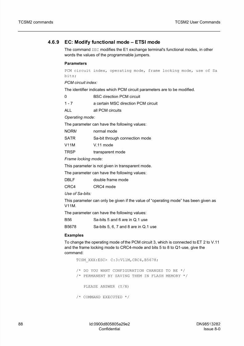
8/10/2019 TCSM COMMAND.pdf
http://slidepdf.com/reader/full/tcsm-commandpdf 88/125
88 DN98513282
Issue 8-0
TCSM2 User Commands
Id:0900d805805a29e2
Confidential
TCSM2 commands
4.6.9 EC: Modify functional mode – ETSI mode
The command ZEC modifies the E1 exchange terminal's functional modes, in other
words the values of the programmable jumpers.
Parameters
PCM circuit index, operating mode, frame locking mode, use of Sa
bits;
PCM circuit index:
The identifier indicates which PCM circuit parameters are to be modified.
0 BSC direction PCM circuit
1 - 7 a certain MSC direction PCM circuit
ALL all PCM circuits
Operating mode:
The parameter can have the following values:
NORM normal mode
SATR Sa-bit through connection mode
V11M V.11 mode
TRSP transparent mode
Frame locking mode:
This parameter is not given in transparent mode.
The parameter can have the following values:
DBLF double frame modeCRC4 CRC4 mode
Use of Sa-bits:
This parameter can only be given if the value of “operating mode” has been given as
V11M.
The parameter can have the following values:
B56 Sa-bits 5 and 6 are in Q.1 use
B5678 Sa-bits 5, 6, 7 and 8 are in Q.1 use
Examples
To change the operating mode of the PCM circuit 3, which is connected to ET 2 to V.11and the frame locking mode to CRC4-mode and bits 5 to 8 to Q1-use, give the
command:
TCSM_XXX:ESC> C:3:V11M,CRC4,B5678;
/* DO YOU WANT CONFIGURATION CHANGES TO BE */
/* PERMANENT BY SAVING THEM IN FLASH MEMORY */
PLEASE ANSWER (Y/N)
/* COMMAND EXECUTED */
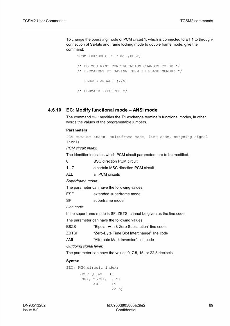
8/10/2019 TCSM COMMAND.pdf
http://slidepdf.com/reader/full/tcsm-commandpdf 89/125
DN98513282
Issue 8-0
89
TCSM2 User Commands TCSM2 commands
Id:0900d805805a29e2
Confidential
To change the operating mode of PCM circuit 1, which is connected to ET 1 to through-
connection of Sa-bits and frame locking mode to double frame mode, give the
command:
TCSM_XXX:ESC> C:1:SATR,DBLF;
/* DO YOU WANT CONFIGURATION CHANGES TO BE */
/* PERMANENT BY SAVING THEM IN FLASH MEMORY */
PLEASE ANSWER (Y/N)
/* COMMAND EXECUTED */
4.6.10 EC: Modify functional mode – ANSI mode
The command ZEC modifies the T1 exchange terminal's functional modes, in other
words the values of the programmable jumpers.
Parameters
PCM circuit index, multiframe mode, line code, outgoing signal
level;
PCM circuit index:
The identifier indicates which PCM circuit parameters are to be modified.
0 BSC direction PCM circuit
1 - 7 a certain MSC direction PCM circuit
ALL all PCM circuits
Superframe mode:
The parameter can have the following values:
ESF extended superframe mode;
SF superframe mode;
Line code:
If the superframe mode is SF, ZBTSI cannot be given as the line code.
The parameter can have the following values:
B8ZS “Bipolar with 8 Zero Substitution” line codeZBTSI “Zero-Byte Time Slot Interchange” line code
AMI “Alternate Mark Inversion” line code
Outgoing signal level:
The parameter can have the values 0, 7.5, 15, or 22.5 decibels.
Syntax
ZEC: PCM circuit index:
(ESF (B8ZS (0
SF), ZBTSI, 7.5;
AMI) 15 22.5)
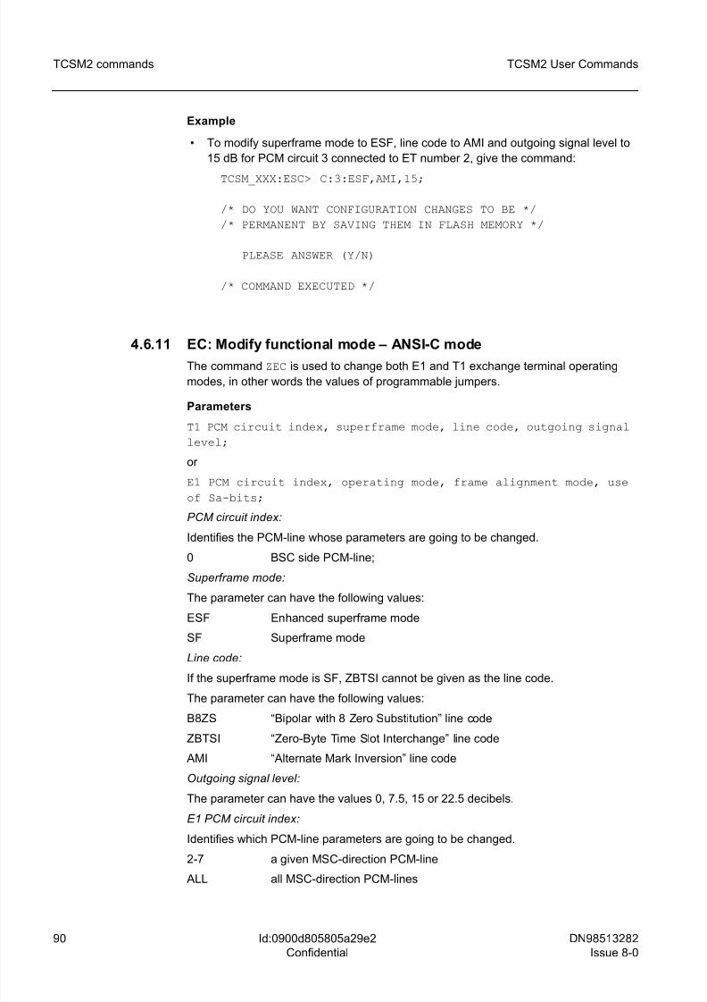
8/10/2019 TCSM COMMAND.pdf
http://slidepdf.com/reader/full/tcsm-commandpdf 90/125
90 DN98513282
Issue 8-0
TCSM2 User Commands
Id:0900d805805a29e2
Confidential
TCSM2 commands
Example
• To modify superframe mode to ESF, line code to AMI and outgoing signal level to
15 dB for PCM circuit 3 connected to ET number 2, give the command:
TCSM_XXX:ESC> C:3:ESF,AMI,15;
/* DO YOU WANT CONFIGURATION CHANGES TO BE */
/* PERMANENT BY SAVING THEM IN FLASH MEMORY */
PLEASE ANSWER (Y/N)
/* COMMAND EXECUTED */
4.6.11 EC: Modify functional mode – ANSI-C modeThe command ZEC is used to change both E1 and T1 exchange terminal operating
modes, in other words the values of programmable jumpers.
Parameters
T1 PCM circuit index, superframe mode, line code, outgoing signal
level;
or
E1 PCM circuit index, operating mode, frame alignment mode, use
of Sa-bits;
PCM circuit index:
Identifies the PCM-line whose parameters are going to be changed.
0 BSC side PCM-line;
Superframe mode:
The parameter can have the following values:
ESF Enhanced superframe mode
SF Superframe mode
Line code:
If the superframe mode is SF, ZBTSI cannot be given as the line code.
The parameter can have the following values:B8ZS “Bipolar with 8 Zero Substitution” line code
ZBTSI “Zero-Byte Time Slot Interchange” line code
AMI “Alternate Mark Inversion” line code
Outgoing signal level:
The parameter can have the values 0, 7.5, 15 or 22.5 decibels.
E1 PCM circuit index:
Identifies which PCM-line parameters are going to be changed.
2-7 a given MSC-direction PCM-line
ALL all MSC-direction PCM-lines
8/10/2019 TCSM COMMAND.pdf
http://slidepdf.com/reader/full/tcsm-commandpdf 91/125
DN98513282
Issue 8-0
91
TCSM2 User Commands TCSM2 commands
Id:0900d805805a29e2
Confidential
Operating mode:
The parameter can have the following values:
NORM normal mode
SATR Sa-bit through connection mode
V11M V.11-mode
TRSP transparent mode
Frame alignment mode:
In transparent operation mode, this parameter does not have a significance, i.e. if the
operating mode is given as TRSP, this parameter is not given.
The parameter can have the following values:
DBLF double frame mode
CRC4 CRC4-mode
Use of Sa-bits:
The Q.1-use of Sa-bits is possible only in V.11 operating mode, so this parameter can
be given only if the parameter “operating mode” value has been given as V11M.
In this case, the parameter can have the following values:
B56 SA-bits 5 and 6 are in Q.1-use;
B5678 SA-bits 5, 6, 7 and 8 are in Q.1-use;
Syntax:
ZEC: PCM circuit index:
(ESF (B8ZS (0
SF), ZBTSI, 7.5;
AMI) 15
22.5)
or
ZEC: PCM circuit index:
(NORM (DBLF (B56
SATR, CRC4) B5678);
V11M
TRSP)
Examples:
• To change the parameters of PCM-line 0, which is connected to ET number 0.
Change over frame mode to ESF, line code to AMI and outgoing signal level to 15
dB, give the command:
TCSM_XXX:ESC> C:0:ESF,AMI,15;
/* DO YOU WANT CONFIGURATION CHANGES TO BE */
/* PERMANENT BY SAVING THEM IN FLASH MEMORY */
PLEASE ANSWER (Y/N)
/* COMMAND EXECUTED */
8/10/2019 TCSM COMMAND.pdf
http://slidepdf.com/reader/full/tcsm-commandpdf 92/125
92 DN98513282
Issue 8-0
TCSM2 User Commands
Id:0900d805805a29e2
Confidential
TCSM2 commands
• To change the parameters of PCM-line 3, which is connected to ET number 1.
Change the operating mode to V.11, the frame alignment mode to CRC4-mode and
put Sa-bits 5 to 8 to Q1-use, give the command:
TCSM_XXX:ESC> C:3:V11M,CRC4,B5678;
/* DO YOU WANT CONFIGURATION CHANGES TO BE */
/* PERMANENT BY SAVING THEM IN FLASH MEMORY */
PLEASE ANSWER (Y/N)
/* COMMAND EXECUTED */
• To change the parameters of PCM-line 4, which is attached to ET number 2 (change
the working/operating mode to the through-connection of Sa-bits and the frame
alignment mode to double frame mode), give the command:
TCSM_XXX:ESC> C:4:SATR,DBLF;
/* DO YOU WANT CONFIGURATION CHANGES TO BE */
/* PERMANENT BY SAVING THEM IN FLASH MEMORY */
PLEASE ANSWER (Y/N)
/* COMMAND EXECUTED */
4.6.12 EI: Display functional modesThe command ZEI displays the T1 exchange terminal's functional modes.
Parameters
PCM circuit index;
PCM circuit index:
The identifier indicates which PCM circuit parameters are to be displayed.
0 BSC direction PCM circuit
1-7 a certain MSC direction PCM circuit
ALL all PCM circuits
Syntax
ZEI: PCM circuit index;
Example
An example from an ANSI application:
• To display functional modes of MSC direction PCM circuit 1 connected to
ET2E/ET2A-1, give the command:
TCSM_XXX:ESC> I:1;
/* T1 FUNCTIONAL MODES */
8/10/2019 TCSM COMMAND.pdf
http://slidepdf.com/reader/full/tcsm-commandpdf 93/125
DN98513282
Issue 8-0
93
TCSM2 User Commands TCSM2 commands
Id:0900d805805a29e2
Confidential
PCM SUPERFRAME LINECODE OUTGOING SIGNAL
MODE MODE LEVEL (dB)
PCM-1 ESF B8ZS 7.5
/* COMMAND EXECUTED */
An example from an ETSI application:
To display functional modes of MSC direction E1 (PCM) circuit 1 connected to ET2E-0,
give the command:
TCSM_XXX:ESC> I:1;
/* PCM DEFINED FUNCTIONAL MODES */
PCM FUNCTIONAL FRAME ALIGNMENT SA-BITS FOR
MODE MODE Q.1 USE
PCM-1 NORM CRC -
/* COMMAND EXECUTED */
4.7 ZU: Unit restart and state handling commands
Command group ZU? in the main menu (TCSM_XXX:LUC>) displays the following sub-
menu with unit restart and state handling commands:
UNIT RESTART AND STATE HANDLING COMMANDS
? ..... MENU/HELP
C ..... CHANGE TCSM2 UNIT STATE
U ..... RESTART TCSM2 UNIT
P ..... RESTART PLUG-IN UNIT
B ..... BLOCK PLUG-IN UNIT
F ..... UNBLOCK PLUG-IN UNIT
Z ..... RETURN TO MAIN LEVEL
TCSM_XXX:USC>
The following sections describe the unit restart and state handling commands(TCSM_XXX:USC>) available in more detail, their use, parameters, syntax and
command examples.
4.7.1 UC: Change TCSM2 unit state
Command ZUC allows you to change the working states of the TCSM2, which are
working (WO-EX) or testing (TE-EX).
g This command can be executed only in the local session, and it is not available if
the LAPD link to the BSC is working.
ParametersWorking state:
8/10/2019 TCSM COMMAND.pdf
http://slidepdf.com/reader/full/tcsm-commandpdf 94/125
94 DN98513282
Issue 8-0
TCSM2 User Commands
Id:0900d805805a29e2
Confidential
TCSM2 commands
The type identifies the type of the unit which is going to be restarted:
WO change the working state of the unit to working mode;
TE change the state of the unit to test mode;
Syntax
ZUC:working state;
Example
To change the state of the unit to executing state, give the command:
TCSM_XXX:USC> ZUC:WO
PLEASE CONFIRM (Y/N)
RESTARTING TCSM UNIT ...
The unit will restart and give the prompt:
TCSM_XXX:USC>
• To change the state of the unit to test state, give the command:
TCSM_XXX:USC> C:TE;
/* COMMAND EXECUTED */
Execution errors
/*** COMMAND NOT POSSIBLE IN REMOTE SESSION ***/
/*** COMMAND NOT ALLOWED ***//*** LAPD IS WORKING ***/
g The LAPD-connection is working. The BSC determines the working state of the
TCSM2-unit.
4.7.2 UU: Restart TCSM2 unit
Command ZUU restarts the whole TCSM2.
Syntax
ZUU;
Example
• To restart the whole TCSM2, give the command:
TCSM_XXX:USC> U;
/* ALL CALLS WILL BE CANCELLED DUE */
/* TO GIVEN COMMAND */
PLEASE CONFIRM (Y/N)
/* COMMAND EXECUTED */
8/10/2019 TCSM COMMAND.pdf
http://slidepdf.com/reader/full/tcsm-commandpdf 95/125
DN98513282
Issue 8-0
95
TCSM2 User Commands TCSM2 commands
Id:0900d805805a29e2
Confidential
4.7.3 UP: Restart plug-in unit
Command ZUP restarts a selected plug-in unit.
Parameters
Plug-in unit type, plug-in unit index;
Plug-in unit type:
Type indicates the plug-in unit type to be restarted:
TR TR12/16 plug-in unit;
ET ET2A/ET2E plug-in unit;
Plug-in unit index:
The parameter indicates the index of the plug-in unit to be restarted; decimal number.0 - 3 ET2A/ET2E plug-in unit index;
0 - 13 TR12/TR16 plug-in unit index;
Syntax
ZUP: plug-in unit type, plug-in unit index;
Examples
• To restart ET2A/ET2E plug-in unit 2, give the command:
TCSM_XXX:USC> P:ET,2;
SYSTEM IS LOADING PLUG-IN UNIT ...
/* PLUG-IN UNIT ET2E-2 RESTARTED */
/* COMMAND EXECUTED */
• To restart TR12 plug-in unit 4, give the command:
TCSM_XXX:USC> P:TR,4;
SYSTEM IS LOADING PLUG-IN UNIT ...
/* PLUG-IN UNIT TR12-4 RESTARTED */
/* COMMAND EXECUTED */
4.7.4 UB: Block plug-in unit
Command ZUB blocks a selected plug-in unit.
Parameters
Plug-in unit type, plug-in unit index;
Plug-in unit type:
The type indicates the plug-in unit type to be blocked:
8/10/2019 TCSM COMMAND.pdf
http://slidepdf.com/reader/full/tcsm-commandpdf 96/125
96 DN98513282
Issue 8-0
TCSM2 User Commands
Id:0900d805805a29e2
Confidential
TCSM2 commands
TR TR12/TR16 plug-in unit;
ET ET2A/ET2E plug-in unit;
Plug-in unit index:
The parameter indicates the index of the plug-in unit to be blocked; decimal number.
0 - 3 ET2A/ET2E plug-in unit index;
0 - 13 TR12/TR16 plug-in unit index;
Syntax
ZUB: plug-in unit type, plug-in unit index;
Examples
• To block ET2A/ET2E plug-in unit 1, give the command:
TCSM_XXX:USC> B:ET,1;
/* PLUG-IN UNIT ET2A-1 BLOCKED */
/* COMMAND EXECUTED */
• To block TR12/TR16 plug-in unit 4, give the command:
TCSM_XXX:USC> B:TR,4;
/* PLUG-IN UNIT TR12-4 BLOCKED */
/* COMMAND EXECUTED */
4.7.5 UF: Unblock plug-in unit
Command ZUF unblocks a blocked plug-in unit.
Parameters
Plug-in unit type, plug-in unit index;
Plug-in unit type:
The type indicates the plug-in unit type to be unblocked:
TR TR12/TR16 plug-in unit;
ET ET2A/ET2E plug-in unit;
Plug-in unit index:
The index indicates which plug-in unit is to be unblocked; decimal number.
0 - 3 ET2A/ET2E plug-in unit index;
0 - 13 TR12/16 plug-in unit index;
Syntax
ZUF: plug-in unit type, plug-in unit index;
Examples
• To unblock the blocked ET2A/ET2E plug-in unit 1, give the command:
8/10/2019 TCSM COMMAND.pdf
http://slidepdf.com/reader/full/tcsm-commandpdf 97/125
DN98513282
Issue 8-0
97
TCSM2 User Commands TCSM2 commands
Id:0900d805805a29e2
Confidential
TCSM_XXX:USC> F:ET,1;
SYSTEM IS LOADING PLUG-IN UNIT ...
/* PLUG-IN UNIT ET2E-1 UNBLOCKED */
/* COMMAND EXECUTED */
• To unblock the blocked TR12/TR16 plug-in unit 4, give the command:
TCSM_XXX:USC> F:TR,4;
/* PLUG-IN UNIT TR12-4 UNBLOCKED */
/* COMMAND EXECUTED */
4.8 I: Statistics commands
Command group ZI? in the main menu (TCSM_XXX:LUC>) displays the following sub-
menu with statistics commands:
STATISTICS COMMANDS
? ..... MENU / HELP
F ..... DISPLAY PCM FAULT RATE COUNTERS
R ..... RESET PCM FAULT RATE COUNTERS
U ..... DISPLAY EXCHANGE TERMINAL RESET COUNTERS
P ..... RESET EXCHANGE TERMINAL RESET COUNTERST ..... DISPLAY TRANSCODER RESET COUNTERS
C ..... RESET TRANSCODER RESET COUNTERS
Z ..... RETURN TO MAIN LEVEL
TCSM_XXX:STA>
The following sections describe the statistics commands (TCSM_XXX:STA>) available
in more detail, their use, parameters, syntax. Command examples are also given.
4.8.1 IF: Display PCM fault rate counters
Command ZIF displays one PCM circuit's short disturbance distribution, frame align-ment signal error distribution, slip quantity and CRC errors of that moment's measure-
ment period.
Parameters
PCM circuit index;
The identifier indicates which PCM circuit's restart counters are to be displayed; decimal
number 0 - 7.
0 BSC direction PCM circuit
1 - 7 a given MSC direction PCM circuit
8/10/2019 TCSM COMMAND.pdf
http://slidepdf.com/reader/full/tcsm-commandpdf 98/125
8/10/2019 TCSM COMMAND.pdf
http://slidepdf.com/reader/full/tcsm-commandpdf 99/125
DN98513282
Issue 8-0
99
TCSM2 User Commands TCSM2 commands
Id:0900d805805a29e2
Confidential
Additional information
The display title indicates trunk circuit statistics counters and values calculated from the
start of a permanent measurement period.
The display then shows disturbances stored in the measurement, their title indicatingwhether they are short disturbances, frame alignment signal errors, slips or CRC errors,
in that order, so that only disturbance statistics given in the command are displayed.
In the case of short disturbances, the first column shows the disturbance type (DIST-
TYPE): NOINSGN = incoming signal missing, AIS = AIS state (continuous 1-state)
detected in incoming line signal, FALOST = frame alignment lost, REMOTE = remote
end disturbances. There are four counters to each disturbance type, where the number
of detected disturbances are recorded according to their length.
Frame alignment signal errors: when calculating bit error ratio, the number of defective
frame alignment signals is counted for a certain integration time. The results are classi-
fied according to the number of defective frame alignment signals detected during inte-
gration time and stored in four counters.
Detected positive and negative slips are displayed for the completed observation period.
When displaying CRC errors, the parameter table lists the following values showing
circuit use to both the local end and remote end:
• TOTAL TIME, for measurement
• AVAIL TIME, available and running
• UNVAIL TIME, unavailable not running
• EFS, error-free seconds
• ES, erroneous seconds
• SES, severely erroneous seconds
• degraded minutes
4.8.2 IR: Reset PCM fault rate counters
Command ZIR resets a selected PCM circuit's statistics counters.
Parameters
PCM circuit index;
The identifier indicates which PCM circuit's statistics counters are to be reset; decimal
number 0 - 7.
0 BSC direction PCM circuit;
1 - 7 a certain MSC direction PCM circuit;
ALL all PCM circuits;
Syntax
ZIR: PCM circuit index;
Example
• To reset PCM circuit 3's statistics counters, give the command:
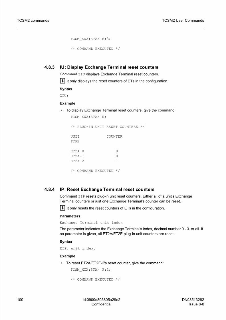
8/10/2019 TCSM COMMAND.pdf
http://slidepdf.com/reader/full/tcsm-commandpdf 100/125
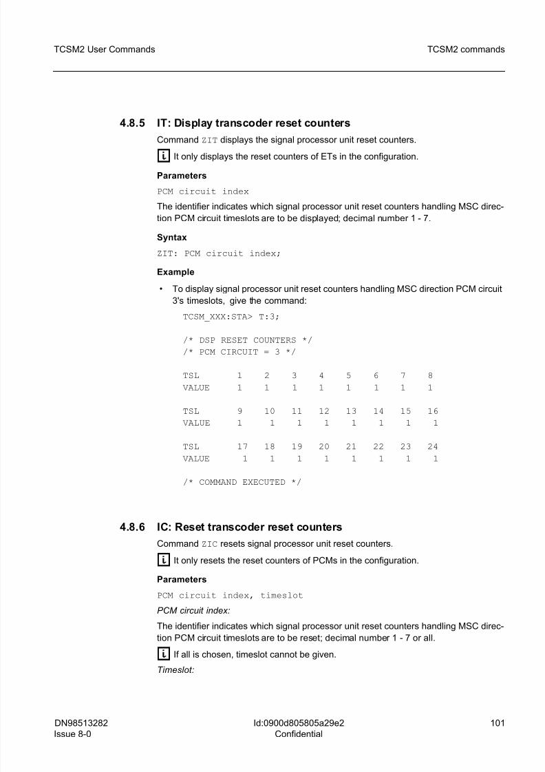
8/10/2019 TCSM COMMAND.pdf
http://slidepdf.com/reader/full/tcsm-commandpdf 101/125
DN98513282
Issue 8-0
101
TCSM2 User Commands TCSM2 commands
Id:0900d805805a29e2
Confidential
4.8.5 IT: Display transcoder reset counters
Command ZIT displays the signal processor unit reset counters.
g It only displays the reset counters of ETs in the configuration.
Parameters
PCM circuit index
The identifier indicates which signal processor unit reset counters handling MSC direc-
tion PCM circuit timeslots are to be displayed; decimal number 1 - 7.
Syntax
ZIT: PCM circuit index;
Example
• To display signal processor unit reset counters handling MSC direction PCM circuit
3's timeslots, give the command:
TCSM_XXX:STA> T:3;
/* DSP RESET COUNTERS */
/* PCM CIRCUIT = 3 */
TSL 1 2 3 4 5 6 7 8
VALUE 1 1 1 1 1 1 1 1
TSL 9 10 11 12 13 14 15 16
VALUE 1 1 1 1 1 1 1 1
TSL 17 18 19 20 21 22 23 24
VALUE 1 1 1 1 1 1 1 1
/* COMMAND EXECUTED */
4.8.6 IC: Reset transcoder reset counters
Command ZIC resets signal processor unit reset counters.
g It only resets the reset counters of PCMs in the configuration.
Parameters
PCM circuit index, timeslot
PCM circuit index:
The identifier indicates which signal processor unit reset counters handling MSC direc-
tion PCM circuit timeslots are to be reset; decimal number 1 - 7 or all.
g If all is chosen, timeslot cannot be given.
Timeslot:
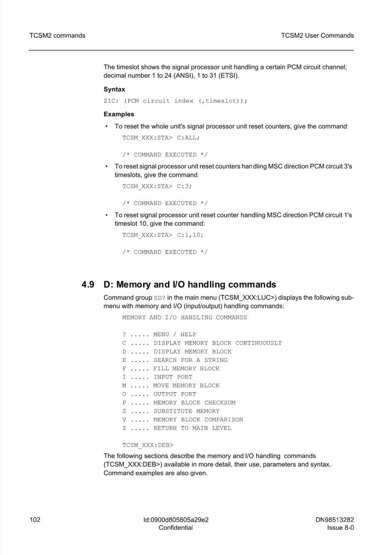
8/10/2019 TCSM COMMAND.pdf
http://slidepdf.com/reader/full/tcsm-commandpdf 102/125
102 DN98513282
Issue 8-0
TCSM2 User Commands
Id:0900d805805a29e2
Confidential
TCSM2 commands
The timeslot shows the signal processor unit handling a certain PCM circuit channel;
decimal number 1 to 24 (ANSI), 1 to 31 (ETSI).
Syntax
ZIC: (PCM circuit index (,timeslot));
Examples
• To reset the whole unit's signal processor unit reset counters, give the command:
TCSM_XXX:STA> C:ALL;
/* COMMAND EXECUTED */
• To reset signal processor unit reset counters handling MSC direction PCM circuit 3's
timeslots, give the command:
TCSM_XXX:STA> C:3;
/* COMMAND EXECUTED */
• To reset signal processor unit reset counter handling MSC direction PCM circuit 1's
timeslot 10, give the command:
TCSM_XXX:STA> C:1,10;
/* COMMAND EXECUTED */
4.9 D: Memory and I/O handling commands
Command group ZD? in the main menu (TCSM_XXX:LUC>) displays the following sub-
menu with memory and I/O (input/output) handling commands:
MEMORY AND I/O HANDLING COMMANDS
? ..... MENU / HELP
C ..... DISPLAY MEMORY BLOCK CONTINUOUSLY
D ..... DISPLAY MEMORY BLOCK
E ..... SEARCH FOR A STRING
F ..... FILL MEMORY BLOCK
I ..... INPUT PORT
M ..... MOVE MEMORY BLOCK
O ..... OUTPUT PORT
P ..... MEMORY BLOCK CHECKSUM
S ..... SUBSTITUTE MEMORY
V ..... MEMORY BLOCK COMPARISON
Z ..... RETURN TO MAIN LEVEL
TCSM_XXX:DEB>
The following sections describe the memory and I/O handling commands
(TCSM_XXX:DEB>) available in more detail, their use, parameters and syntax.
Command examples are also given.
8/10/2019 TCSM COMMAND.pdf
http://slidepdf.com/reader/full/tcsm-commandpdf 103/125
DN98513282
Issue 8-0
103
TCSM2 User Commands TCSM2 commands
Id:0900d805805a29e2
Confidential
4.9.1 DC: Display memory block continuously
Command ZDC continuously displays a memory block which fills the screen. The
command is used in the same way as command D. The window to be displayed can be
moved with the cursor control keys as follows:
ARROW KEY DOWN takes you half a screen forward
ARROW KEY UP takes you half a screen backwards
Execution errors:
/*** CHOSEN AREA DOES NOT FIT ONTO DISPLAY ***/
/*** START ADDRESS BIGGER THAN STOP ADDRESS ***/
4.9.2 DD: Display memory blockCommand ZDD displays up to 64 kbytes memory in bytes (D), in words (DW), double
words (DD) or pointers (DP). You can exit the display by hitting the ESC key. In the byte
display the corresponding ASCII characters are shown on the right side of the screen.
The default display shows 16 bytes, 8 words or 4 double words/pointers on one line.
These values can be changed as required. If the value given is greater than the default
line length, the line is displayed with the default length.
Syntax
ZDD(W/P/D):start pointer(,end offset(,row length));
Examples
• To display in bytes the memory block 40.0 - 40.2, give the command:
TCSM_XXX:DEB> D:40.0,2;
0040.0000: 00 28 C0 .(.
• To display memory word 40.3300, give the command:
TCSM_XXX:DEB> DW:40.3300;
0040.3300: 0000
• To display as pointer memory block F800.0 - F800.A. Maximum 3 pointers per row,
give the command:TCSM_XXX:DEB> DP:F800.2,A,3;
F800.0002: FFFF.FFFF FFFF.FFFF FFFF.FFFF
• To display as double words the memory block 0.0 - 0.F, give the command:
TCSM_XXX:DEB> DD:0.0,F;
0000.0000: FF040687 FF040687 FF040687 E2001C43
Execution errors:
/*** START ADDRESS BIGGER THAN STOP ADDRESS ***/
8/10/2019 TCSM COMMAND.pdf
http://slidepdf.com/reader/full/tcsm-commandpdf 104/125
104 DN98513282
Issue 8-0
TCSM2 User Commands
Id:0900d805805a29e2
Confidential
TCSM2 commands
4.9.3 DE: Search for a string
Command ZDE searches for a string or for data in a given memory block address. The
string can be 1 to 16 characters long. The search can be interrupted with the ESC key.
Syntax
ZDE: start pointer, < end pointer/end
offset>,<data((,data)*15)/'character ((character)* 15>;
Examples
• To search for data AB,05,EF in memory block 0.0 - 4000.FF, give the command:
TCSM_XXX:DEB> E:0.0,4000.FF,AB,05,EF;
FOUND AT: 0000.CBB2
FOUND AT: 3000.0000
SEARCHED • To search for ASCII character string 'ABCDEF' in memory block 4000.0 - 7000.0,
give the command:
TCSM_XXX:DEB> E:4000.0,7000.0,'ABCDEF;
SEARCHED
Execution errors:
/*** START ADDRESS BIGGER THAN STOP ADDRESS ***/
4.9.4 DF: Fill memory block
Command ZDF fills the memory block with a bit string of maximum 16 bytes long. The
bit string is given either in HEX bytes separated by commas or as ASCII characters.
Upon execution, the success of the command is checked. If the start address is greater
than the end address, the filling is not performed.
Syntax
ZDF:start pointer,<end pointer/end offset>,
<data((,data)*15)/'character ((character)*15)>;
Examples
• To fill memory block 3000.0 - 3000.F with byte string 1,2,3,4, give the command:
TCSM_XXX:DEB> F:3000.0,3000.F,1,2,3,4;
FILLED
• To attempt to fill memory block 0.FF - 0.0 with byte string 1,2,3,4, give the command:
TCSM_XXX:DEB> F:0.FF,0.0,1,2,3,4;
/*** START ADDRESS BIGGER THAN STOP ADDRESS ***/
• To fill memory block 3000.0 - 3000.4F with ASCII character string 'DEBUGGER',
give the command:
8/10/2019 TCSM COMMAND.pdf
http://slidepdf.com/reader/full/tcsm-commandpdf 105/125
DN98513282
Issue 8-0
105
TCSM2 User Commands TCSM2 commands
Id:0900d805805a29e2
Confidential
TCSM_XXX:DEB> F:3000.0,4F,'DEBUGGER;
FILLED
• To attempt to fill memory block 3000.0 - 3000.FF with a too long ASCII characterstring, give the command:
TCSM_XXX:DEB> F:3000.0,FF,'ALLTOOLONGSEQUENCE;
F:3000.0,FF,'<== SYNTAX ERROR
• To fill memory block F800.0 - F800.FF with byte BB, give the command:
TCSM_XXX:DEB> F:F800.0,FF,BB;
/*** CANNOT WRITE TO F800.0000 ***/
Execution errors
/*** CANNOT WRITE TO: <address> ***/
/*** START ADDRESS BIGGER THAN STOP ADDRESS ***/
4.9.5 DI: Input port
Command ZDI continuously reads a given port's contents either in bytes (I) or words
(IW).
Syntax
ZDI(W):port address;
Execute the command by hitting the spacebar: <SPACE>.
Escape by hitting <ENTER>.
Examples
• To read bytes in I/O port FE80, give the command:
TCSM_XXX:DEB> I:FE80 <SPACE>
12 1B 41 41
• To read words in I/O port EFF6, give the command:
TCSM_XXX:DEB> IW:EFF6 <SPACE>
FF47 FE45 FF47
4.9.6 DM: Move memory block
Command ZDM copies a memory block to another address. Upon execution the success
of the command is checked. If the source start address is greater than the source end
address, copying is not performed. If the target start address is between the source start
address and the source end address, copying is done from the block's end towards its
beginning. Otherwise copying is done from the block's beginning.
8/10/2019 TCSM COMMAND.pdf
http://slidepdf.com/reader/full/tcsm-commandpdf 106/125
106 DN98513282
Issue 8-0
TCSM2 User Commands
Id:0900d805805a29e2
Confidential
TCSM2 commands
Syntax
ZDM: source pointer, <end pointer/end offset>,destination
pointer;
Examples
• To copy memory block 400.0 - 400.FFF to the address 800.0, give the command:
TCSM_XXX:DEB> M:400.0,FFF,800.0;
MOVED
• To copy memory block 400.0 - 400.FFF to the address 400.10, give the command:
TCSM_XXX:DEB> M:400.0,FFF,400.10;
MOVED
• To copy memory block F800.0 - F800.FF to the address F900.0, give the command:TCSM_XXX:DEB> M:F800.0,FF,F900.0;
/*** CANNOT WRITE TO F900.0000 ***/
• To copy memory block 2000.0 - 4000.FFFF to the address 8000.0, give the
command:
TCSM_XXX:DEB> M:2000.0,4000.FFFF,8000.0;
MOVED
• To attempt to copy memory block 400.FF - 400.0 to the address 800.0, give the
command:TCSM_XXX:DEB> M:400.FF,0,800.0;
/*** START ADDRESS BIGGER THAN STOP ADDRESS ***/
Execution errors
/*** CANNOT WRITE TO <address> ***/
/*** START ADDRESS BIGGER THAN STOP ADDRESS ***/
4.9.7 DO: Output port
Command ZDO outputs selected data to a given port either in bytes (O) or words (OW).
It outputs to the port every time the <SPACE BAR> is pressed. You would normally give
a number and then press the <SPACE BAR>. Zero (0) is the default value if no value is
given. If some other value is given, it is used as the default value for the duration of the
command execution.
Syntax
ZDO(W):port (data)*;
Execute the command by hitting the spacebar: <SPACE>.
Escape by hitting <ENTER>
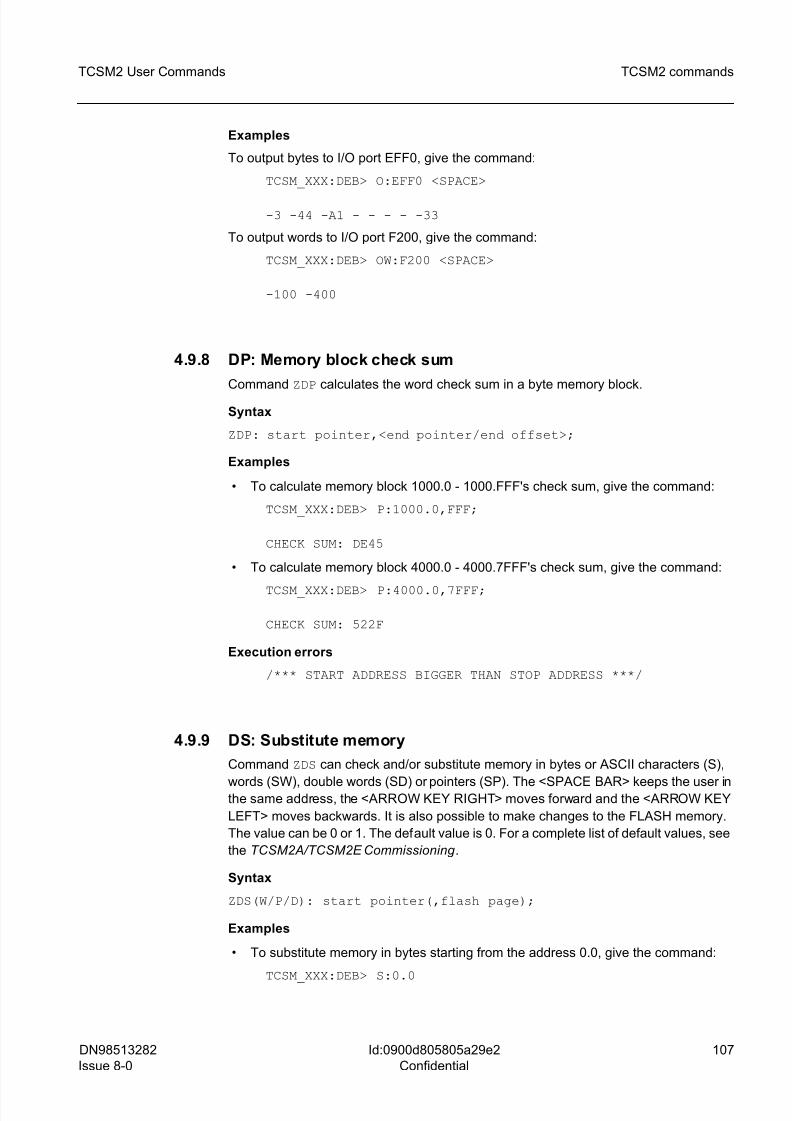
8/10/2019 TCSM COMMAND.pdf
http://slidepdf.com/reader/full/tcsm-commandpdf 107/125
DN98513282
Issue 8-0
107
TCSM2 User Commands TCSM2 commands
Id:0900d805805a29e2
Confidential
Examples
To output bytes to I/O port EFF0, give the command:
TCSM_XXX:DEB> O:EFF0 <SPACE>
-3 -44 -A1 - - - - -33
To output words to I/O port F200, give the command:
TCSM_XXX:DEB> OW:F200 <SPACE>
-100 -400
4.9.8 DP: Memory block check sum
Command ZDP calculates the word check sum in a byte memory block.
Syntax
ZDP: start pointer,<end pointer/end offset>;
Examples
• To calculate memory block 1000.0 - 1000.FFF's check sum, give the command:
TCSM_XXX:DEB> P:1000.0,FFF;
CHECK SUM: DE45
• To calculate memory block 4000.0 - 4000.7FFF's check sum, give the command:
TCSM_XXX:DEB> P:4000.0,7FFF;
CHECK SUM: 522F
Execution errors
/*** START ADDRESS BIGGER THAN STOP ADDRESS ***/
4.9.9 DS: Substitute memory
Command ZDS can check and/or substitute memory in bytes or ASCII characters (S),
words (SW), double words (SD) or pointers (SP). The <SPACE BAR> keeps the user inthe same address, the <ARROW KEY RIGHT> moves forward and the <ARROW KEY
LEFT> moves backwards. It is also possible to make changes to the FLASH memory.
The value can be 0 or 1. The default value is 0. For a complete list of default values, see
the TCSM2A/TCSM2E Commissioning .
Syntax
ZDS(W/P/D): start pointer(,flash page);
Examples
• To substitute memory in bytes starting from the address 0.0, give the command:
TCSM_XXX:DEB> S:0.0
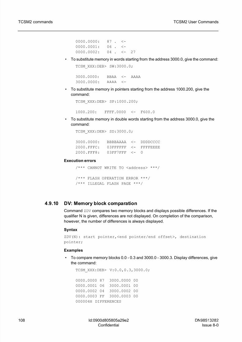
8/10/2019 TCSM COMMAND.pdf
http://slidepdf.com/reader/full/tcsm-commandpdf 108/125
108 DN98513282
Issue 8-0
TCSM2 User Commands
Id:0900d805805a29e2
Confidential
TCSM2 commands
0000.0000: 87 . <-
0000.0001: 06 . <-
0000.0002: 04 . <- 27
• To substitute memory in words starting from the address 3000.0, give the command:TCSM_XXX:DEB> SW:3000.0;
3000.0000: BBAA <- AAAA
3000.0000: AAAA <-
• To substitute memory in pointers starting from the address 1000.200, give the
command:
TCSM_XXX:DEB> SP:1000.200;
1000.200: FFFF.0000 <- F600.0
• To substitute memory in double words starting from the address 3000.0, give thecommand:
TCSM_XXX:DEB> SD:3000.0;
3000.0000: BBBBAAAA <- DDDDCCCC
2000.FFFC: 03FFFFFF <- FFFFEEEE
2000.FFF8: 03FF7FFF <- 0
Execution errors
/*** CANNOT WRITE TO <address> ***/
/*** FLASH OPERATION ERROR ***//*** ILLEGAL FLASH PAGE ***/
4.9.10 DV: Memory block comparation
Command ZDV compares two memory blocks and displays possible differences. If the
qualifier N is given, differences are not displayed. On completion of the comparison,
however, the number of differences is always displayed.
Syntax
ZDV(N): start pointer,<end pointer/end offset>, destination
pointer;
Examples
• To compare memory blocks 0.0 - 0.3 and 3000.0 - 3000.3. Display differences, give
the command:
TCSM_XXX:DEB> V:0.0,0.3,3000.0;
0000.0000 87 3000.0000 00
0000.0001 06 3000.0001 00
0000.0002 04 3000.0002 00
0000.0003 FF 3000.0003 00
000004H DIFFERENCES
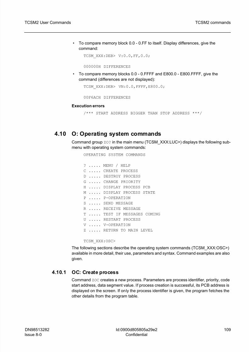
8/10/2019 TCSM COMMAND.pdf
http://slidepdf.com/reader/full/tcsm-commandpdf 109/125
DN98513282
Issue 8-0
109
TCSM2 User Commands TCSM2 commands
Id:0900d805805a29e2
Confidential
• To compare memory block 0.0 - 0.FF to itself. Display differences, give the
command:
TCSM_XXX:DEB> V:0.0,FF,0.0;
000000H DIFFERENCES
• To compare memory blocks 0.0 - 0.FFFF and E800.0 - E800.FFFF, give the
command (differences are not displayed):
TCSM_XXX:DEB> VN:0.0,FFFF,E800.0;
00F6ACH DIFFERENCES
Execution errors
/*** START ADDRESS BIGGER THAN STOP ADDRESS ***/
4.10 O: Operating system commands
Command group ZO? in the main menu (TCSM_XXX:LUC>) displays the following sub-
menu with operating system commands:
OPERATING SYSTEM COMMANDS
? ..... MENU / HELP
C ..... CREATE PROCESS
D ..... DESTROY PROCESS
G ..... CHANGE PRIORITY
H ..... DISPLAY PROCESS PCB
M ..... DISPLAY PROCESS STATE
P ..... P-OPERATION
S ..... SEND MESSAGE
R ..... RECEIVE MESSAGE
T ..... TEST IF MESSAGES COMING
U ..... RESTART PROCESS
V ..... V-OPERATION
Z ..... RETURN TO MAIN LEVEL
TCSM_XXX:OSC>
The following sections describe the operating system commands (TCSM_XXX:OSC>)
available in more detail, their use, parameters and syntax. Command examples are also
given.
4.10.1 OC: Create process
Command ZOC creates a new process. Parameters are process identifier, priority, code
start address, data segment value. If process creation is successful, its PCB address is
displayed on the screen. If only the process identifier is given, the program fetches the
other details from the program table.
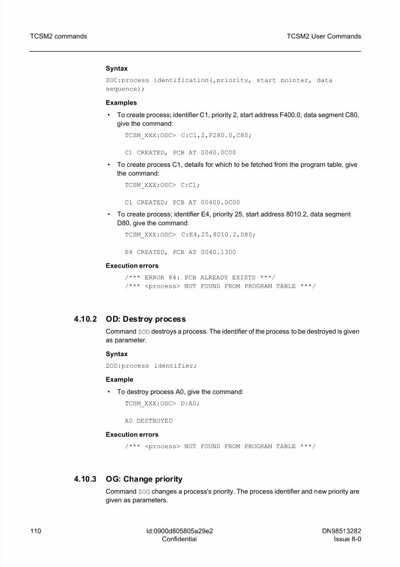
8/10/2019 TCSM COMMAND.pdf
http://slidepdf.com/reader/full/tcsm-commandpdf 110/125
110 DN98513282
Issue 8-0
TCSM2 User Commands
Id:0900d805805a29e2
Confidential
TCSM2 commands
Syntax
ZOC:process identification(,priority, start pointer, data
sequence);
Examples
• To create process; identifier C1, priority 2, start address F400.0, data segment C80,
give the command:
TCSM_XXX:OSC> C:C1,2,F280.0,C80;
C1 CREATED, PCB AT 0040.0C00
• To create process C1, details for which to be fetched from the program table, give
the command:
TCSM_XXX:OSC> C:C1;
C1 CREATED; PCB AT 00400.0C00
• To create process; identifier E4, priority 25, start address 8010.2, data segment
D80, give the command:
TCSM_XXX:OSC> C:E4,25,8010.2,D80;
E4 CREATED, PCB AT 0040.1300
Execution errors
/*** ERROR 84: PCB ALREADY EXISTS ***/
/*** <process> NOT FOUND FROM PROGRAM TABLE ***/
4.10.2 OD: Destroy process
Command ZOD destroys a process. The identifier of the process to be destroyed is given
as parameter.
Syntax
ZOD:process identifier;
Example
• To destroy process A0, give the command:
TCSM_XXX:OSC> D:A0;
A0 DESTROYED
Execution errors
/*** <process> NOT FOUND FROM PROGRAM TABLE ***/
4.10.3 OG: Change priority
Command ZOG changes a process's priority. The process identifier and new priority are
given as parameters.
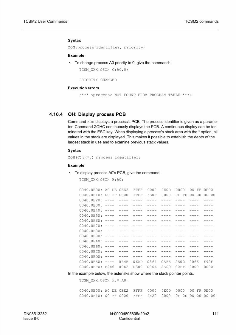
8/10/2019 TCSM COMMAND.pdf
http://slidepdf.com/reader/full/tcsm-commandpdf 111/125
DN98513282
Issue 8-0
111
TCSM2 User Commands TCSM2 commands
Id:0900d805805a29e2
Confidential
Syntax
ZOG:process identifier, priority;
Example
• To change process A0 priority to 0, give the command:
TCSM_XXX:OSC> G:A0,0;
PRIORITY CHANGED
Execution errors
/*** <process> NOT FOUND FROM PROGRAM TABLE ***/
4.10.4 OH: Display process PCB
Command ZOH displays a process's PCB. The process identifier is given as a parame-
ter. Command ZOHC continuously displays the PCB. A continuous display can be ter-
minated with the ESC key. When displaying a process's stack area with the * option, all
values in the stack are displayed. This makes it possible to establish the depth of the
largest stack in use and to examine previous stack values.
Syntax
ZOH(C):(*,) process identifier;
Example
• To display process A0's PCB, give the command:
TCSM_XXX:OSC> H:A0;
0040.0E00: A0 DE 0EE2 FFFF 0000 0E0D 0000 00 FF 0E00
0040.0E10: 00 FF 0000 FFFF 330F 0000 0F FE 00 00 00 00
0040.0E20: ---- ---- ---- ---- ---- ---- ---- ----
0040.0E30: ---- ---- ---- ---- ---- ---- ---- ----
0040.0E40: ---- ---- ---- ---- ---- ---- ---- ----
0040.0E50: ---- ---- ---- ---- ---- ---- ---- ----
0040.0E60: ---- ---- ---- ---- ---- ---- ---- ----
0040.0E70: ---- ---- ---- ---- ---- ---- ---- ----
0040.0E80: ---- ---- ---- ---- ---- ---- ---- ----
0040.0E90: ---- ---- ---- ---- ---- ---- ---- ----
0040.0EA0: ---- ---- ---- ---- ---- ---- ---- ----
0040.0EB0: ---- ---- ---- ---- ---- ---- ---- ----
0040.0EC0: ---- ---- ---- ---- ---- ---- ---- ----
0040.0ED0: ---- ---- ---- ---- ---- ---- ---- ----
0040.0EE0: ---- 044B 06AD 0564 0EFE 2E00 0066 F92F
0040.0EF0: F246 00D2 D300 000A 2E00 00FF 0000 0000
In the example below, the asterisks show where the stack pointer points.
TCSM_XXX:OSC> H:*,A0;
0040.0E00: A0 DE 0EE2 FFFF 0000 0E0D 0000 00 FF 0E00
0040.0E10: 00 FF 0000 FFFF 4420 0000 0F 0E 00 00 00 00
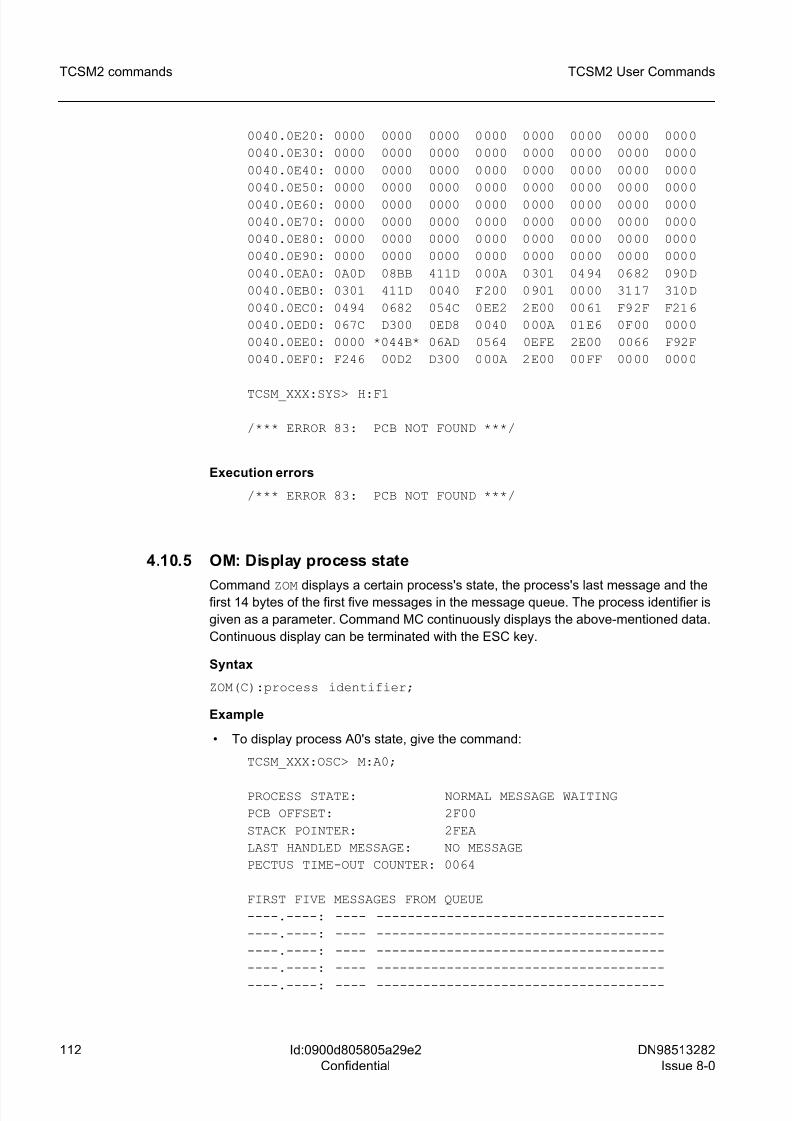
8/10/2019 TCSM COMMAND.pdf
http://slidepdf.com/reader/full/tcsm-commandpdf 112/125
112 DN98513282
Issue 8-0
TCSM2 User Commands
Id:0900d805805a29e2
Confidential
TCSM2 commands
0040.0E20: 0000 0000 0000 0000 0000 0000 0000 0000
0040.0E30: 0000 0000 0000 0000 0000 0000 0000 0000
0040.0E40: 0000 0000 0000 0000 0000 0000 0000 0000
0040.0E50: 0000 0000 0000 0000 0000 0000 0000 0000
0040.0E60: 0000 0000 0000 0000 0000 0000 0000 0000
0040.0E70: 0000 0000 0000 0000 0000 0000 0000 0000
0040.0E80: 0000 0000 0000 0000 0000 0000 0000 0000
0040.0E90: 0000 0000 0000 0000 0000 0000 0000 0000
0040.0EA0: 0A0D 08BB 411D 000A 0301 0494 0682 090D
0040.0EB0: 0301 411D 0040 F200 0901 0000 3117 310D
0040.0EC0: 0494 0682 054C 0EE2 2E00 0061 F92F F216
0040.0ED0: 067C D300 0ED8 0040 000A 01E6 0F00 0000
0040.0EE0: 0000 *044B* 06AD 0564 0EFE 2E00 0066 F92F
0040.0EF0: F246 00D2 D300 000A 2E00 00FF 0000 0000
TCSM_XXX:SYS> H:F1
/*** ERROR 83: PCB NOT FOUND ***/
Execution errors
/*** ERROR 83: PCB NOT FOUND ***/
4.10.5 OM: Display process state
Command ZOM displays a certain process's state, the process's last message and thefirst 14 bytes of the first five messages in the message queue. The process identifier is
given as a parameter. Command MC continuously displays the above-mentioned data.
Continuous display can be terminated with the ESC key.
Syntax
ZOM(C):process identifier;
Example
• To display process A0's state, give the command:
TCSM_XXX:OSC> M:A0;
PROCESS STATE: NORMAL MESSAGE WAITING
PCB OFFSET: 2F00
STACK POINTER: 2FEA
LAST HANDLED MESSAGE: NO MESSAGE
PECTUS TIME-OUT COUNTER: 0064
FIRST FIVE MESSAGES FROM QUEUE
----.----: ---- -------------------------------------
----.----: ---- -------------------------------------
----.----: ---- -------------------------------------
----.----: ---- -------------------------------------
----.----: ---- -------------------------------------
8/10/2019 TCSM COMMAND.pdf
http://slidepdf.com/reader/full/tcsm-commandpdf 113/125
DN98513282
Issue 8-0
113
TCSM2 User Commands TCSM2 commands
Id:0900d805805a29e2
Confidential
Execution errors
/*** ERROR 83: PCB NOT FOUND ***/
4.10.6 OP: P-Operation
Command ZOP makes a P operation on a certain semaphore. The semaphore address
is given as a parameter. The operating system requires that semaphores be located in
its data segment, so that no more than the offset part of the semaphore address is
required. In a P operation, a time control parameter can also be given, when required.
If no V operation is performed on a semaphore during time control, the operating system
performs it. Time control length is given in multiples of 100 ms. If the address is given
correctly, the screen displays the semaphore's value before the P operation. When
using time control the command also displays how much time control was left when the
V operation was performed.
Syntax
ZOP:semaphore offset(,maximum waiting time);
Examples
• To perform a P operation on a semaphore with offset part address 521, give the
command:
TCSM_XXX:OSC> P: 521;
SEMAPHORE VALUE BEFORE P-OPERATION = 00
• To perform a P operation on a semaphore with offset part address 521. V operationwill be waited for 500 ms, maximum, give the command:
TCSM_XXX:OSC> P: 521,5;
SEMAPHORE VALUE BEFORE P-OPERATION = 00
TIME OUT
4.10.7 OR: Receive message
Command ZOR receives messages of 125 bytes maximum length from a certain process
(selective reception) or from any process (general reception). Command RA immedi-ately returns the message as it was received. When a message arrives, it is displayed
on the screen. The parameter given is a process identifier in selective reception and FF
in general reception. In addition, a time control parameter can be given. Or if it is not
given, the R command operation can be terminated by hitting the ESC key. If there is no
incoming message during time control, the text TIME OUT is displayed on the screen.
Otherwise, the message received is displayed together with how much time control was
left. Time control length is given in multiples of 100 ms.
Syntax
ZOR(A)(:process identification(,time control));
8/10/2019 TCSM COMMAND.pdf
http://slidepdf.com/reader/full/tcsm-commandpdf 114/125
114 DN98513282
Issue 8-0
TCSM2 User Commands
Id:0900d805805a29e2
Confidential
TCSM2 commands
Examples
• To receive a message from the A0 process, give the command:
TCSM_XXX:OSC> R:A0;
RECEIVED MESSAGE = 0A 05 A0
0004 05 06 07 08 09
• To receive a message from the A0 process. Wait 500 ms, maximum. The received
message is returned, give the command:
TCSM_XXX:OSC> RA:A0,5;
RECEIVED MESSAGE = 0A 05 A0
0004 05 06 07 08 09
TIME LEFT 0002
SEND OK
• To receive a message from the A0 process. Wait 500 ms, maximum, give the
command:
TCSM_XXX:OSC> R:A0,5;
TIME OUT
• To receive a message from any process, give the command:
TCSM_XXX:OSC> R;
RECEIVED MESSAGE = 03 75 AA
4.10.8 OS: Send message
Command ZOS sends messages to other processes. Maximum message length is 35
bytes. The message to be sent can be typed on the screen the moment it is sent (S) or
written in advance to memory and the message address (SM) given at the moment of
sending. A third alternative is to return the message most recently received (SA). The
first byte in the message indicates the message length. At the moment the message
being written is sent the length can be given as *, whereon the program counts the
number of bytes given). The second byte indicates the receiving computer. At the
moment the message being written is sent the receiving computer can be given as *.
The message is always sent to one's own unit. The third byte indicates the receiving
process. The first 0-30 bytes of the message may be given.
Syntax
ZOS<A/M:message address/:<message length>/*>,<computer
identification /*>,program identification, (message
identifier)(,(data))*30>;
Examples
• To send a message (6 bytes long) to the A0 process, give the command:
TCSM_XXX:OSC> S:*,*,A0,0001,0F;
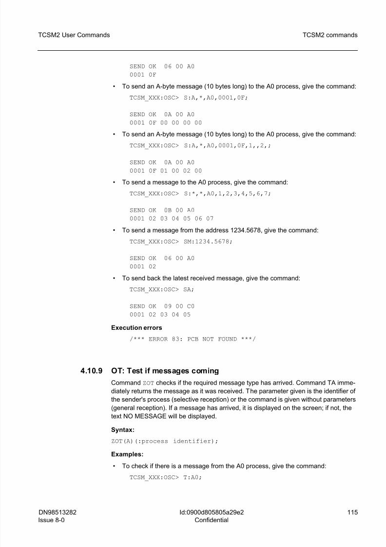
8/10/2019 TCSM COMMAND.pdf
http://slidepdf.com/reader/full/tcsm-commandpdf 115/125
DN98513282
Issue 8-0
115
TCSM2 User Commands TCSM2 commands
Id:0900d805805a29e2
Confidential
SEND OK 06 00 A0
0001 0F
• To send an A-byte message (10 bytes long) to the A0 process, give the command:
TCSM_XXX:OSC> S:A,*,A0,0001,0F;
SEND OK 0A 00 A0
0001 0F 00 00 00 00
• To send an A-byte message (10 bytes long) to the A0 process, give the command:
TCSM_XXX:OSC> S:A,*,A0,0001,0F,1,,2,;
SEND OK 0A 00 A0
0001 0F 01 00 02 00
• To send a message to the A0 process, give the command:
TCSM_XXX:OSC> S:*,*,A0,1,2,3,4,5,6,7;
SEND OK 0B 00 A0
0001 02 03 04 05 06 07
• To send a message from the address 1234.5678, give the command:
TCSM_XXX:OSC> SM:1234.5678;
SEND OK 06 00 A0
0001 02
• To send back the latest received message, give the command:
TCSM_XXX:OSC> SA;
SEND OK 09 00 C0
0001 02 03 04 05
Execution errors
/*** ERROR 83: PCB NOT FOUND ***/
4.10.9 OT: Test if messages coming
Command ZOT checks if the required message type has arrived. Command TA imme-diately returns the message as it was received. The parameter given is the identifier of
the sender's process (selective reception) or the command is given without parameters
(general reception). If a message has arrived, it is displayed on the screen; if not, the
text NO MESSAGE will be displayed.
Syntax:
ZOT(A)(:process identifier);
Examples:
• To check if there is a message from the A0 process, give the command:
TCSM_XXX:OSC> T:A0;
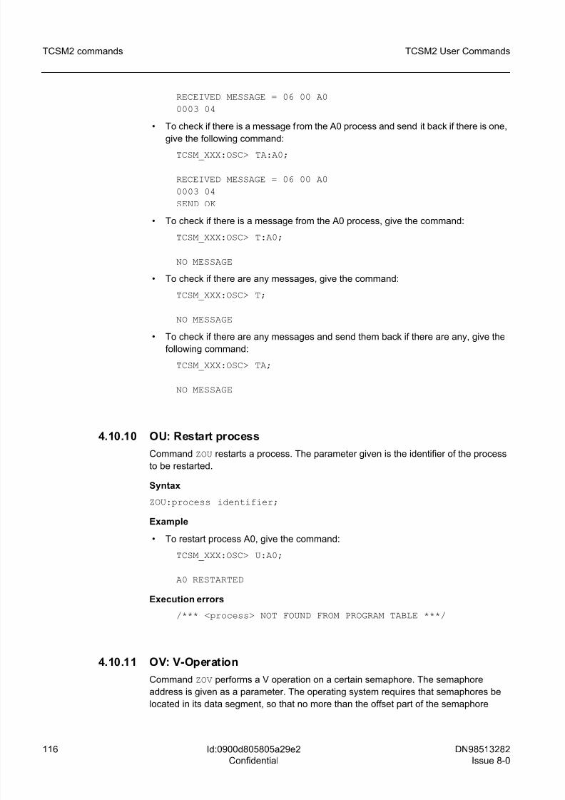
8/10/2019 TCSM COMMAND.pdf
http://slidepdf.com/reader/full/tcsm-commandpdf 116/125
116 DN98513282
Issue 8-0
TCSM2 User Commands
Id:0900d805805a29e2
Confidential
TCSM2 commands
RECEIVED MESSAGE = 06 00 A0
0003 04
• To check if there is a message from the A0 process and send it back if there is one,
give the following command:TCSM_XXX:OSC> TA:A0;
RECEIVED MESSAGE = 06 00 A0
0003 04
SEND OK
• To check if there is a message from the A0 process, give the command:
TCSM_XXX:OSC> T:A0;
NO MESSAGE
• To check if there are any messages, give the command:TCSM_XXX:OSC> T;
NO MESSAGE
• To check if there are any messages and send them back if there are any, give the
following command:
TCSM_XXX:OSC> TA;
NO MESSAGE
4.10.10 OU: Restart process
Command ZOU restarts a process. The parameter given is the identifier of the process
to be restarted.
Syntax
ZOU:process identifier;
Example
• To restart process A0, give the command:
TCSM_XXX:OSC> U:A0;
A0 RESTARTED
Execution errors
/*** <process> NOT FOUND FROM PROGRAM TABLE ***/
4.10.11 OV: V-Operation
Command ZOV performs a V operation on a certain semaphore. The semaphore
address is given as a parameter. The operating system requires that semaphores be
located in its data segment, so that no more than the offset part of the semaphore
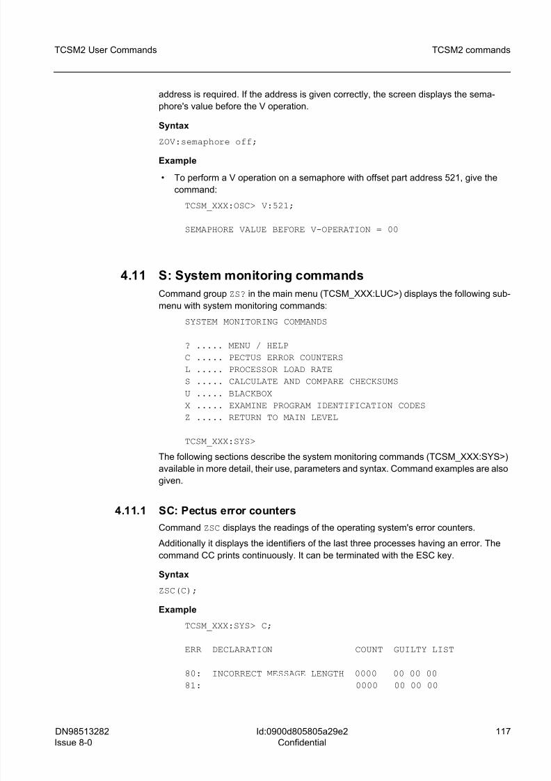
8/10/2019 TCSM COMMAND.pdf
http://slidepdf.com/reader/full/tcsm-commandpdf 117/125
DN98513282
Issue 8-0
117
TCSM2 User Commands TCSM2 commands
Id:0900d805805a29e2
Confidential
address is required. If the address is given correctly, the screen displays the sema-
phore's value before the V operation.
Syntax
ZOV:semaphore off;
Example
• To perform a V operation on a semaphore with offset part address 521, give the
command:
TCSM_XXX:OSC> V:521;
SEMAPHORE VALUE BEFORE V-OPERATION = 00
4.11 S: System monitoring commandsCommand group ZS? in the main menu (TCSM_XXX:LUC>) displays the following sub-
menu with system monitoring commands:
SYSTEM MONITORING COMMANDS
? ..... MENU / HELP
C ..... PECTUS ERROR COUNTERS
L ..... PROCESSOR LOAD RATE
S ..... CALCULATE AND COMPARE CHECKSUMS
U ..... BLACKBOX
X ..... EXAMINE PROGRAM IDENTIFICATION CODESZ ..... RETURN TO MAIN LEVEL
TCSM_XXX:SYS>
The following sections describe the system monitoring commands (TCSM_XXX:SYS>)
available in more detail, their use, parameters and syntax. Command examples are also
given.
4.11.1 SC: Pectus error counters
Command ZSC displays the readings of the operating system's error counters.
Additionally it displays the identifiers of the last three processes having an error. Thecommand CC prints continuously. It can be terminated with the ESC key.
Syntax
ZSC(C);
Example
TCSM_XXX:SYS> C;
ERR DECLARATION COUNT GUILTY LIST
80: INCORRECT MESSAGE LENGTH 0000 00 00 00
81: 0000 00 00 00
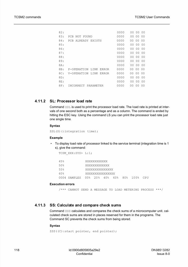
8/10/2019 TCSM COMMAND.pdf
http://slidepdf.com/reader/full/tcsm-commandpdf 118/125
118 DN98513282
Issue 8-0
TCSM2 User Commands
Id:0900d805805a29e2
Confidential
TCSM2 commands
82: 0000 00 00 00
83: PCB NOT FOUND 0000 00 00 00
84: PCB ALREADY EXISTS 0000 00 00 00
85: 0000 00 00 00
86: 0000 00 00 00
87: 0000 00 00 00
88: 0000 00 00 00
89: 0000 00 00 00
8A: 0000 00 00 00
8B: P-OPERATION LINK ERROR 0000 00 00 00
8C: V-OPERATION LINK ERROR 0000 00 00 00
8D: 0000 00 00 00
8E: 0000 00 00 00
8F: INCORRECT PARAMETER 0000 00 00 00
4.11.2 SL: Processor load rate
Command ZSL is used to print the processor load rate. The load rate is printed at inter-
vals of one second both as a percentage and as a column. The command is ended by
hitting the ESC key. Using the command LS you can print the processor load rate just
one single time.
Syntax
ZSL(S)(:integration time);
Example
• To display load rate of processor linked to the service terminal (integration time is 1
s), give the command:
TCSM_XXX:SYS> L:1;
45% XXXXXXXXXXXX
50% XXXXXXXXXXXXX
55% XXXXXXXXXXXXXXX
60% XXXXXXXXXXXXXXXX
0004 SAMPLES 00% 20% 40% 60% 80% 100% CPU
Execution errors
/*** CANNOT SEND A MESSAGE TO LOAD METERING PROCESS ***/
4.11.3 SS: Calculate and compare check sums
Command ZSS calculates and compares the check sums of a microcomputer unit. cal-
culated check sums are stored in places reserved for them in the programs. The
Command SC prevents the check sums from being stored.
Syntax
ZSS((C):start pointer, end pointer);
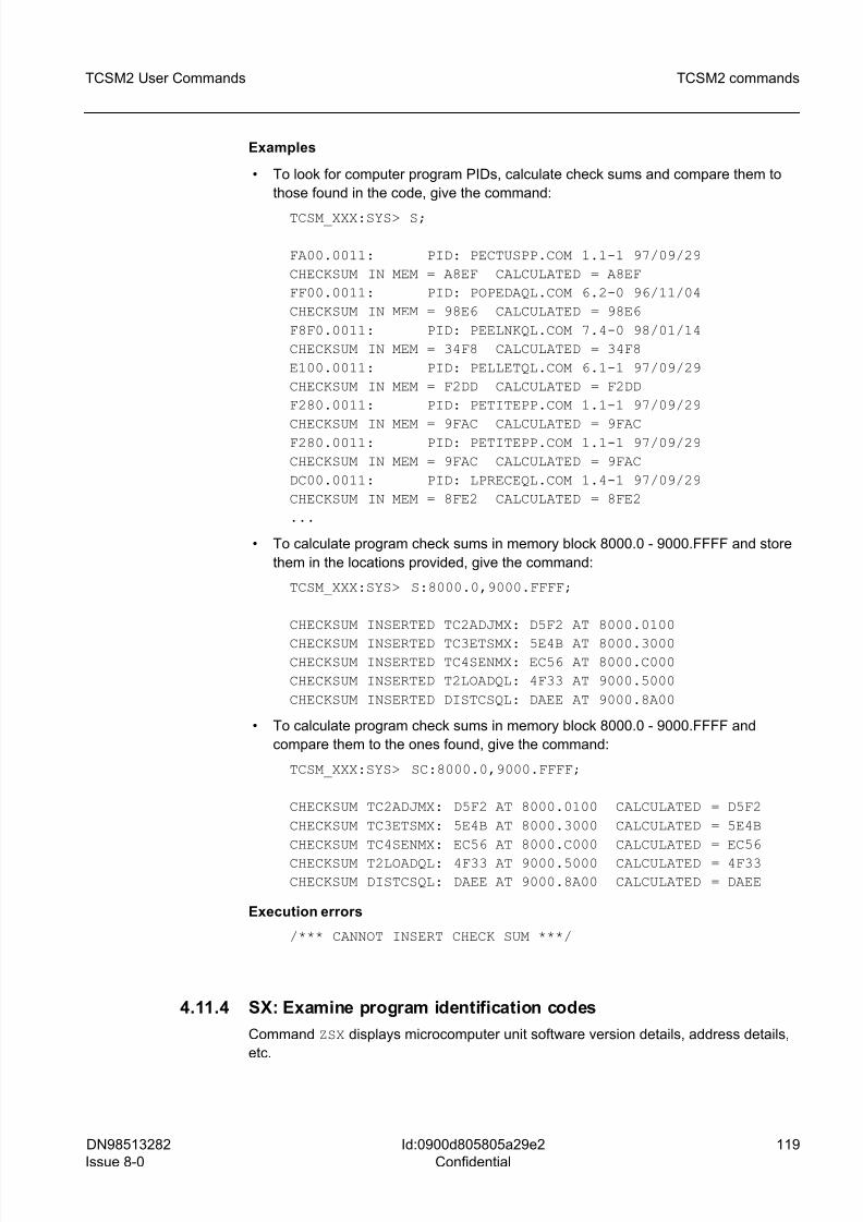
8/10/2019 TCSM COMMAND.pdf
http://slidepdf.com/reader/full/tcsm-commandpdf 119/125
DN98513282
Issue 8-0
119
TCSM2 User Commands TCSM2 commands
Id:0900d805805a29e2
Confidential
Examples
• To look for computer program PIDs, calculate check sums and compare them to
those found in the code, give the command:
TCSM_XXX:SYS> S;
FA00.0011: PID: PECTUSPP.COM 1.1-1 97/09/29
CHECKSUM IN MEM = A8EF CALCULATED = A8EF
FF00.0011: PID: POPEDAQL.COM 6.2-0 96/11/04
CHECKSUM IN MEM = 98E6 CALCULATED = 98E6
F8F0.0011: PID: PEELNKQL.COM 7.4-0 98/01/14
CHECKSUM IN MEM = 34F8 CALCULATED = 34F8
E100.0011: PID: PELLETQL.COM 6.1-1 97/09/29
CHECKSUM IN MEM = F2DD CALCULATED = F2DD
F280.0011: PID: PETITEPP.COM 1.1-1 97/09/29
CHECKSUM IN MEM = 9FAC CALCULATED = 9FACF280.0011: PID: PETITEPP.COM 1.1-1 97/09/29
CHECKSUM IN MEM = 9FAC CALCULATED = 9FAC
DC00.0011: PID: LPRECEQL.COM 1.4-1 97/09/29
CHECKSUM IN MEM = 8FE2 CALCULATED = 8FE2
...
• To calculate program check sums in memory block 8000.0 - 9000.FFFF and store
them in the locations provided, give the command:
TCSM_XXX:SYS> S:8000.0,9000.FFFF;
CHECKSUM INSERTED TC2ADJMX: D5F2 AT 8000.0100
CHECKSUM INSERTED TC3ETSMX: 5E4B AT 8000.3000CHECKSUM INSERTED TC4SENMX: EC56 AT 8000.C000
CHECKSUM INSERTED T2LOADQL: 4F33 AT 9000.5000
CHECKSUM INSERTED DISTCSQL: DAEE AT 9000.8A00
• To calculate program check sums in memory block 8000.0 - 9000.FFFF and
compare them to the ones found, give the command:
TCSM_XXX:SYS> SC:8000.0,9000.FFFF;
CHECKSUM TC2ADJMX: D5F2 AT 8000.0100 CALCULATED = D5F2
CHECKSUM TC3ETSMX: 5E4B AT 8000.3000 CALCULATED = 5E4B
CHECKSUM TC4SENMX: EC56 AT 8000.C000 CALCULATED = EC56
CHECKSUM T2LOADQL: 4F33 AT 9000.5000 CALCULATED = 4F33
CHECKSUM DISTCSQL: DAEE AT 9000.8A00 CALCULATED = DAEE
Execution errors
/*** CANNOT INSERT CHECK SUM ***/
4.11.4 SX: Examine program identification codes
Command ZSX displays microcomputer unit software version details, address details,
etc.
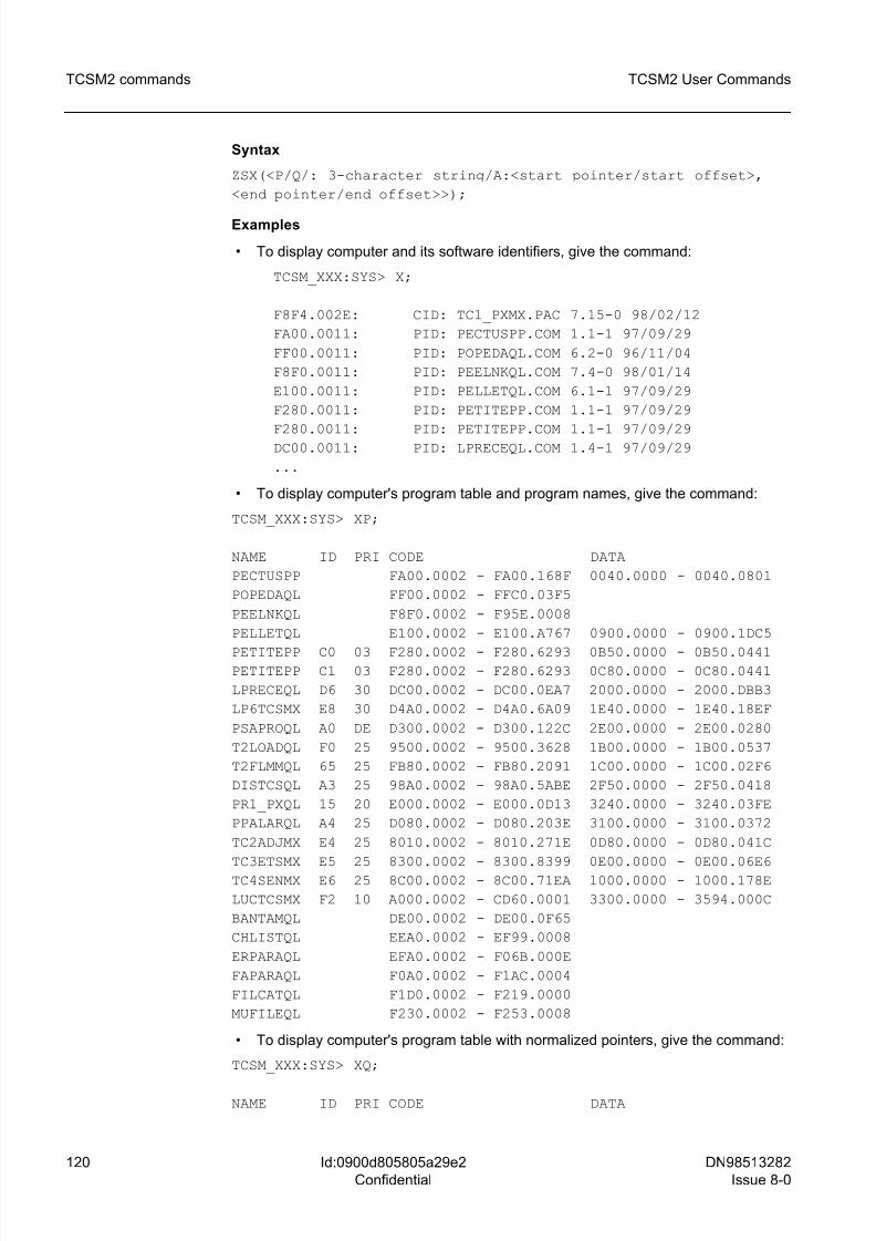
8/10/2019 TCSM COMMAND.pdf
http://slidepdf.com/reader/full/tcsm-commandpdf 120/125
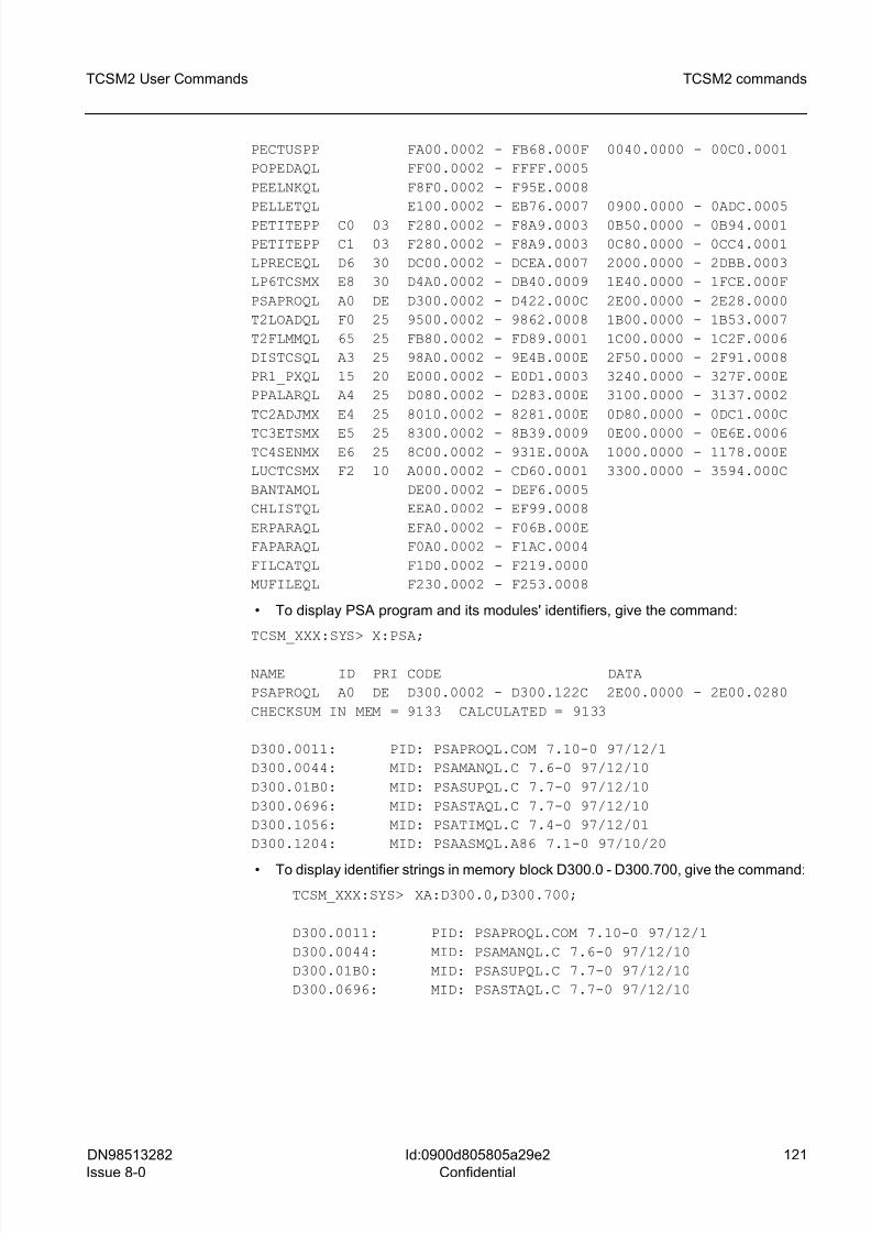
8/10/2019 TCSM COMMAND.pdf
http://slidepdf.com/reader/full/tcsm-commandpdf 121/125
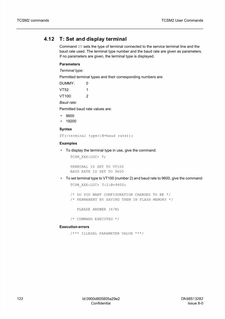
8/10/2019 TCSM COMMAND.pdf
http://slidepdf.com/reader/full/tcsm-commandpdf 122/125
122 DN98513282
Issue 8-0
TCSM2 User Commands
Id:0900d805805a29e2
Confidential
TCSM2 commands
4.12 T: Set and display terminal
Command ZT sets the type of terminal connected to the service terminal line and the
baud rate used. The terminal type number and the baud rate are given as parameters.
If no parameters are given, the terminal type is displayed.
Parameters
Terminal type:
Permitted terminal types and their corresponding numbers are:
DUMMY: 0
VT52: 1
VT100: 2
Baud rate:
Permitted baud rate values are:
• 9600
• 19200
Syntax
ZT(:terminal type(:B=baud rate));
Examples
• To display the terminal type in use, give the command:
TCSM_XXX:LUC> T;
TERMINAL IS SET TO VT100BAUD RATE IS SET TO 9600
• To set terminal type to VT100 (number 2) and baud rate to 9600, give the command:
TCSM_XXX:LUC> T:2:B=9600;
/* DO YOU WANT CONFIGURATION CHANGES TO BE */
/* PERMANENT BY SAVING THEM IN FLASH MEMORY */
PLEASE ANSWER (Y/N)
/* COMMAND EXECUTED */
Execution errors
/*** ILLEGAL PARAMETER VALUE ***/
8/10/2019 TCSM COMMAND.pdf
http://slidepdf.com/reader/full/tcsm-commandpdf 123/125
DN98513282
Issue 8-0
123
TCSM2 User Commands Error messages in TCSM2 user commands
Id:0900d805805a29e5
Confidential
5 Error messages in TCSM2 user commandsThe semantic error messages that can be displayed on the screen can be found below.
/*** SEMANTIC ERROR ***/ /*** Error text (see below) ***/The error text describes the error in more detail.
/*** EXCESSIVE PARAMETER ***/
There is an extra parameter or too many parameters in the command.
/*** ILLEGAL PARAMETER VALUE ***/
The parameter entered is undefined and illegal.
/*** MISSING PARAMETER ***/
Obligatory parameter or parameters missing.
8/10/2019 TCSM COMMAND.pdf
http://slidepdf.com/reader/full/tcsm-commandpdf 124/125
124 DN98513282
Issue 8-0
TCSM2 User Commands
Id:0900d805805a29e8
Confidential
Additional information to TCSM2 user commands
6 Additional information to TCSM2 user
commands
Alarm list in TCSM2 user commands
0630 SYNCHRONIZATION SIGNAL CHANGED
1900 DEGRADED SLIP FREQUENCY
2202 ET FAILURE
2205 ET2 FAILURE
2374 FILE SPACE ERROR IN PREPROCESSOR UNIT
2375 DYNAMIC FLAGPOOL FULL IN PREPROCESSOR UNIT
2631 OPERATION MODE CHANGED TO PLESIOCHRONOUS
2632 OSCILLATOR FAILURE
2636 FAILURE IN OUTGOING CLOCK SIGNAL
2641 FAILURE IN SYNCHRONIZATION SIGNAL
2900 INCOMING SIGNAL MISSING
2909 AIS RECEIVED
2910 FRAMING ERROR
2912 BIT ERROR RATE OVER LIMIT
2915 FAULT RATE MONITORING
2923 CRC BIT ERROR RATIO OVER LIMIT
2924 REMOTE END CRC BIT ERROR RATIO OVER LIMIT2925 SLIP FREQUENCY LIMIT EXCEEDED
2943 BLUE ALARM
2944 YELLOW ALARM
2950 TRCO FAILURE
2951 LOCAL USER LOGGED IN
2952 TRANSCODER PLUG-IN UNIT FAILURE
2954 NO TRAU FRAME SYNCHRONIZATION
2955 TRANSCODER CHANNEL FAILURE
2956 PLUG-IN UNIT LOCALLY BLOCKED
2958 FAULTY TIME SLOT IN TESTING OF TCSM UNIT
2959 THROUGH CONNECTED CHANNEL FAILURE
2960 WIRED ALARM FROM ANOTHER TCSM2
2962 SW PACKAGE MISSING
Cable connections (RS-232C)
A) Connections for cable: VDU to TCSM/TRCO
No handshaking signals are available at the TCSM end of the cable. Only pins 2, 3 and
7 are connected.
B) Connections for cable: PC to TCSM/TRCO
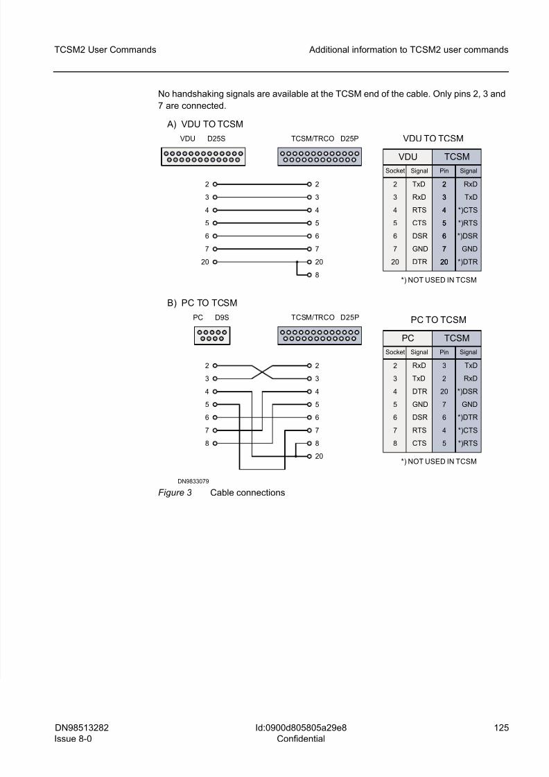
8/10/2019 TCSM COMMAND.pdf
http://slidepdf.com/reader/full/tcsm-commandpdf 125/125
TCSM2 User Commands Additional information to TCSM2 user commands
No handshaking signals are available at the TCSM end of the cable. Only pins 2, 3 and
7 are connected.
2
3
4
5
6
7
20
2
3
4
5
6
7
20
8
2
3
4
5
6
7
8
2
3
4
5
6
7
8
20
VDU D25S TCSM/TRCO D25P
A) VDU TO TCSM
2
3
4
5
6
7
20
TxD
RxD
RTS
CTS
DSR
GND
DTR
2
3
4
5
6
7
20
RxD
TxD
*)CTS
*)RTS
*)DSR
GND
*)DTR
2
3
4
5
6
7
20
*) NOT USED IN TCSM
PC D9S TCSM/TRCO D25P
B) PC TO TCSM
2
3
4
5
6
7
8
RxD
TxD
DTR
GND
DSR
RTS
CTS
3
2
20
7
6
4
TxD
RxD
*)DSR
GND
*)DTR
*)CTS
*)RTS
Socket Signal Pin Signal
PC TCSM
5
Socket Signal Pin Signal
VDU TCSM
VDU TO TCSM
*) NOT USED IN TCSM
PC TO TCSM