Embed Size (px)
Citation preview

IM-P068-37 ST Issue 6 1
TD42S2 Thermodynamic Steam Trap
Installation and Maintenance Instructions
IM-P068-37ST Issue 6
6190050/6
1. Safetyinformation
2. General productinformation
3. Installation
4. Commissioning
5. Operation
6. Maintenance
7. Spareparts
Printed in the UK © Copyright 2011

IM-P068-37 ST Issue 62
Safe operation of this product can only be guaranteed if it is properly installed, commissioned, used and maintained by qualified personnel (see Section 1.11) in compliance with the operating instructions. General installation and safety instructions for pipeline and plant construction, as well as the proper use of tools and safety equipment must also be complied with.
1.1 Intended useReferring to the Installation and Maintenance Instructions, name-plate and Technical Information Sheet, check that the product is suitable for the intended use / application. This product complies with the requirements of the European Pressure Equipment Directive 97 / 23 / EC and falls within category 'SEP'. It should be noted that products within this category are required by the Directive not to carry the mark.
i) This product has been specifically designed for use on steam, air or condensate / water, which is in Group 2 of the above mentioned Pressure Equipment Directive. The products’ use on other fluids may be possible but, if this is contemplated, Spirax Sarco should be contacted to confirm the suitability of the product for the application being considered.
ii) Check material suitability, pressure and temperature and their maximum and minimum values. If the maximum operating limits of the product are lower than those of the system in which it is being fitted, or if malfunction of the product could result in a dangerous overpressure or overtemperature occurrence, ensure a safety device is included in the system to prevent such over-limit situations.
iii) Determine the correct installation situation and direction of fluid flow.
iv) Spirax Sarco products are not intended to withstand external stresses that may be induced by any system to which they are fitted. It is the responsibility of the installer to consider these stresses and take adequate precautions to minimise them.
v) Remove protection covers from all connections and protective film from all name-plates, where appropriate, before installation on steam or other high temperature applications.
1.2 AccessEnsure safe access and if necessary a safe working platform (suitably guarded) before attempting to work on the product. Arrange suitable lifting gear if required.
1.3 LightingEnsure adequate lighting, particularly where detailed or intricate work is required.
1.4 Hazardous liquids or gases in the pipelineConsider what is in the pipeline or what may have been in the pipeline at some previous time. Consider: flammable materials, substances hazardous to health, extremes of temperature.
1. Safety information

IM-P068-37 ST Issue 6 3
1.5 Hazardous environment around the productConsider: explosion risk areas, lack of oxygen (e.g. tanks, pits), dangerous gases, extremes of temperature, hot surfaces, fire hazard (e.g. during welding), excessive noise, moving machinery.
1.6 The systemConsider the effect on the complete system of the work proposed. Will any proposed action (e.g. closing isolation valves, electrical isolation) put any other part of the system or any personnel at risk? Dangers might include isolation of vents or protective devices or the rendering ineffective of controls or alarms. Ensure isolation valves are turned on and off in a gradual way to avoid system shocks.
1.7 Pressure systems Ensure that any pressure is isolated and safely vented to atmospheric pressure. Consider double isolation (double block and bleed) and the locking or labelling of closed valves. Do not assume that the system has depressurised even when the pressure gauge indicates zero.
1.8 TemperatureAllow time for temperature to normalise after isolation to avoid danger of burns.
1.9 Tools and consumablesBefore starting work ensure that you have suitable tools and /or consumables available. Use only genuine Spirax Sarco replacement parts.
1.10 Protective clothingConsider whether you and/or others in the vicinity require any protective clothing to protect against the hazards of, for example, chemicals, high/low temperature, radiation, noise, falling objects, and dangers to eyes and face.
1.11 Permits to workAll work must be carried out or be supervised by a suitably competent person.Installation and operating personnel should be trained in the correct use of the product according to the Installation and Maintenance Instructions.Where a formal 'permit to work' system is in force it must be complied with. Where there is no such system, it is recommended that a responsible person should know what work is going on and, where necessary, arrange to have anassistant whose primary responsibility is safety.Post 'warning notices' if necessary.
1.12 HandlingManual handling of large and/or heavy products may present a risk of injury. Lifting, pushing, pulling, carrying or supporting a load by bodily force can cause injury particularly to the back. You are advised to assess the risks taking into account the task, the individual, the load and the working environment and use the appropriate handling method depending on the circumstances of the work being done.
IM-P068-37 ST Issue 64
1.13 Residual hazardsIn normal use the external surface of the product may be very hot. If used at the maximum permitted operating conditions the surface temperature of some products may reach temperatures of 500°C (932°F).Many products are not self-draining. Take due care when dismantling or removing the product from an installation (refer to 'Maintenance instructions').
1.14 FreezingProvision must be made to protect products which are not self-draining against frost damage in environments where they may be exposed to temperatures below freezing point.
1.15 DisposalUnless otherwise stated in the Installation and Maintenance Instructions, this product is recyclable and no ecological hazard is anticipated with its disposal providing due care is taken.
1.16 Returning productsCustomers and stockists are reminded that under EC Health, Safety and Environment Law, when returning products to Spirax Sarco they must provide information on any hazards and the precautions to be taken due to contamination residues or mechanical damage which may present a health, safety or environmental risk. This information must be provided in writing including Health and Safety data sheets relating to any substances identified as hazardous or potentially hazardous.

IM-P068-37 ST Issue 6 5
2. General product information2.1 General descriptionThe TD42S2 is a thermodynamic steam trap with forged steel body and socket weld ends.
Optional extras
Insulating cover To prevent the trap being unduly influenced by excessive heat loss
such as when subjected to low outside temperatures, wind, rain etc.
Integral blowdown A BDV1 or BDV2 can be fitted to the strainer cap, alternatively thevalve strainer cap can be drilled, tapped and plugged " BSP or NPT.
StandardsThis product fully complies with the requirements of the European Pressure Equipment Directive 97 /23 / EC.
CertificationThis product is available with certification to EN 10204 3.1. Note: All certification / inspection requirements must be stated at the time of order placement.
Note: For addtional information see Technical Information Sheet TI-P068-07.
Fig. 1 TD42S2 thermodynamic steam trap
2.2 Sizes and pipe connections½"LC, ¾"LC, 1"LC, ½", ¾" and 1".Socket weld ends to ASME (ANSI) B 16.11 Schedule 80 / BS 3799 Class 3000 lb.

IM-P068-37 ST Issue 66
��
���
���
���
���
�� �� �� �� ��
���
���������������������
� ��� ��� ��� ��� ��� ��� ������
Pressure bar g
Tem
per
atur
e °C
The product must not be used in this region.
The product should not be used in this region.
Note: Upon prolonged exposure to temperatures above 425°C (797°F), the carbide phase of steel may be converted to graphite. Permissible but not recommended for prolonged use above 425°C (797°F).
Body design conditions ASME / ANSI 300
PMA Maximum allowable pressure 51 bar g @ 38°C (739 psi g @ 100°F)
TMA Maximum allowable temperature 427°C @ 28 bar g (800°F @ 406 psi g)
Minimum allowable temperature 0°C (32°F)
PMO
Maximum operating pressure 42 bar g (609 psi g)
for saturated steam service
TMO Maximum operating temperature 400°C @ 34 bar g (752°F @ 493 psi g)
Minimum operating temperature 0°C (32°F)Note: For lower operating temperatures consult Spirax Sarco.
DPMX Maximum differentail pressure 42 bar (609 psi)
PMOB Maximum operating backpressure should not exceed 80% of the upstream pressure
Minimum operating differential 0.25 bar (3.6 psi)pressure for satisfactory operation
Designed for a maximum cold hydraulic test pressure of: 76 bar g (1102 psi g)
Pressure psi g
Temp
erature °F
Steamsaturationcurve
2.3 Pressure / temperature limits (ISO 6552)

IM-P068-37 ST Issue 6 7
3. InstallationNote: Before actioning any installation observe the 'Safety information' in Section 1.
Referring to the Installation and Maintenance Instructions, name-plate and Technical Information Sheet, check that the product is suitable for the intended installation:
3.1 Check materials, pressure and temperature and their maximum values. If the maximum operating limit of the product is lower than that of the system in which it is being fitted, ensure that a safety device is included in the system to prevent overpressurisation.
3.2 Determine the correct installation situation and the direction of fluid flow.
3.3 Remove protective covers from all connections and protective film from all name plates, where appropriate, before installation on steam or other high temperature applications.
3.4 The trap should preferably be installed in the horizontal plane, with a small drop leg preceding it. Suitable isolation valves must be installed to allow for safe maintenance and trap replacement. Consideration should be given to a suitable method for testing
the correct operation of the trap. This may be a sight glass or a Spiratec system. Sight glasses must be positioned a minimum of 1 m (3 ft) downstream of any blast-action traps. Where the trap discharges into a closed return system, a non-return valve should be fitted downstream to prevent return flow.
3.5 Isolation valves must be installed to allow for safe maintenance and trap replacement.
3.6 Always open isolation valves slowly until normal operating conditions are achieved - this will avoid system shocks. Check for leaks and correct operation.
3.7 Welding into the pipeline - For specific weld procedures consult the relevant National and International welding standards.
Note: If the trap is to discharge to atmosphere ensure it is to a safe place, the discharging fluid may be at a temperature of 100°C (212°F).
IM-P068-37 ST Issue 68
6. MaintenanceNote: Before actioning any maintenance programme observe
the 'Safety information' in Section 1.
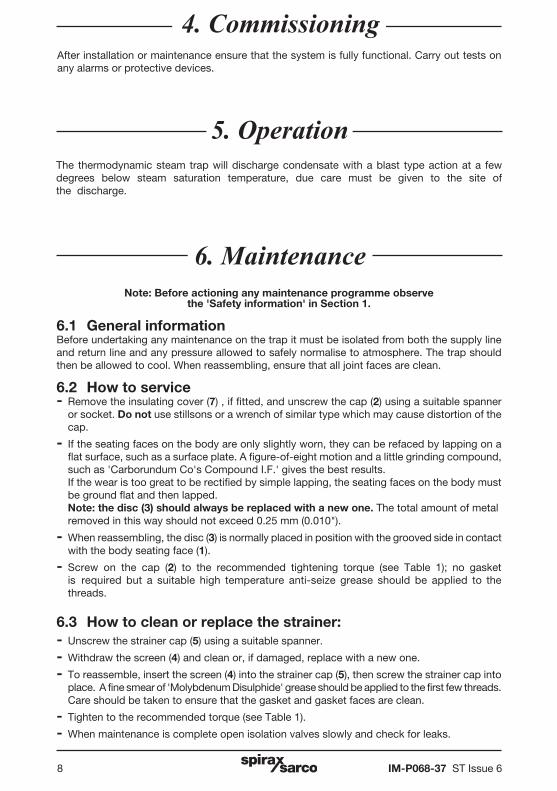
6.1 General information Before undertaking any maintenance on the trap it must be isolated from both the supply line and return line and any pressure allowed to safely normalise to atmosphere. The trap should then be allowed to cool. When reassembling, ensure that all joint faces are clean.
6.2 How to service - Remove the insulating cover (7) , if fitted, and unscrew the cap (2) using a suitable spanner
or socket. Do not use stillsons or a wrench of similar type which may cause distortion of the cap.
- If the seating faces on the body are only slightly worn, they can be refaced by lapping on a flat surface, such as a surface plate. A figure-of-eight motion and a little grinding compound, such as 'Carborundum Co's Compound I.F.' gives the best results.
If the wear is too great to be rectified by simple lapping, the seating faces on the body must be ground flat and then lapped.
Note: the disc (3) should always be replaced with a new one. The total amount of metal removed in this way should not exceed 0.25 mm (0.010").
- When reassembling, the disc (3) is normally placed in position with the grooved side in contact with the body seating face (1).
- Screw on the cap (2) to the recommended tightening torque (see Table 1); no gasket is required but a suitable high temperature anti-seize grease should be applied to the threads.
6.3 How to clean or replace the strainer:- Unscrew the strainer cap (5) using a suitable spanner.
- Withdraw the screen (4) and clean or, if damaged, replace with a new one.
- To reassemble, insert the screen (4) into the strainer cap (5), then screw the strainer cap into place. A fine smear of 'Molybdenum Disulphide' grease should be applied to the first few threads. Care should be taken to ensure that the gasket and gasket faces are clean.
- Tighten to the recommended torque (see Table 1).
- When maintenance is complete open isolation valves slowly and check for leaks.
After installation or maintenance ensure that the system is fully functional. Carry out tests on any alarms or protective devices.
4. Commissioning
The thermodynamic steam trap will discharge condensate with a blast type action at a few degrees below steam saturation temperature, due care must be given to the site of the discharge.
5. Operation

IM-P068-37 ST Issue 6 9
4
7
3
2
5
6
Table 1 Recommended tightening torques orItem Part Size N m lbf ft mm
½" LC 36 A/F 87 - 97 62 - 69
¾" LC 36 A/F 87 - 97 62 - 69
2
Cap 1" LC 36 A/F 87 - 97 62 - 69
½" 41 A/F 100 - 110 72 - 79
¾" 41 A/F 100 - 110 72 - 79
1" 55 A/F 140 - 160 100 - 114
5 Strainer cap (all sizes) 27 A/F M24 120 - 135 88 - 100
1
Fig. 2

IM-P068-37 ST Issue 610
4
7
3
6
The spare parts available are shown in solid outline. Parts drawn in broken line are not supplied as spares.
Available sparesDisc (packet of 3) 3
Strainer screen and gasket 4, 6
Strainer cap gasket (packet of 3) 6
Insulating cover 7
How to order sparesAlways order spares by using the description given in the column headed 'Available spares' and state the size and type of trap.
Example: 1 - Strainer screen and gasket for a Spirax Sarco ½" TD42S2 thermodynamic steam trap.
7. Spare parts
Fig. 3

IM-P068-37 ST Issue 6 11

IM-P068-37 ST Issue 612