Embed Size (px)
Citation preview
Your Preferred Partner for Industrial Flow Control & Specialty Equipment

Training Objective1. Scope of work
-To understand the scope of our work in this project2. Fundamentals of Steam Trap
-To understand the function of steam trap3. Installation Configuration
- To understand the type of configuration for steam trap4. Installation Procedure
- To understand the right procedure of installation5. Flow of Communication
- To know the organization of PIC at site6. Q & A session & Review GPP3
Presentation Outline
1. Scope of work2. Fundamentals of Steam Trap, Strainer &
Valve3. Installation Configuration4. Installation Procedure5. Authorities6. Q & A session & Review GPP3

Scope of Work
“ENGINEERING, PROCUREMENT, CONSTRUCTION AND COMMISSIONING FOR STEAM TRAP PROJECT AT
GAS PROCESSING PLANT A (GPP A), PLANT OPERATIONS DIVISION, PETRONAS GAS BERHAD”
“To Replace Steam Traps for Dripping & Tracing only (Exclude Process Traps)”
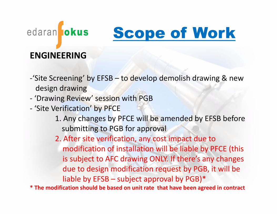
Scope of WorkENGINEERING
-‘Site Screening’ by EFSB – to develop demolish drawing & new design drawing
- ‘Drawing Review’ session with PGB- ‘Site Verification’ by PFCE
1. Any changes by PFCE will be amended by EFSB before submitting to PGB for approval
2. After site verification, any cost impact due to modification of installation will be liable by PFCE (this is subject to AFC drawing ONLY. If there’s any changes due to design modification request by PGB, it will be liable by EFSB – subject approval by PGB)*
* The modification should be based on unit rate that have been agreed in contract
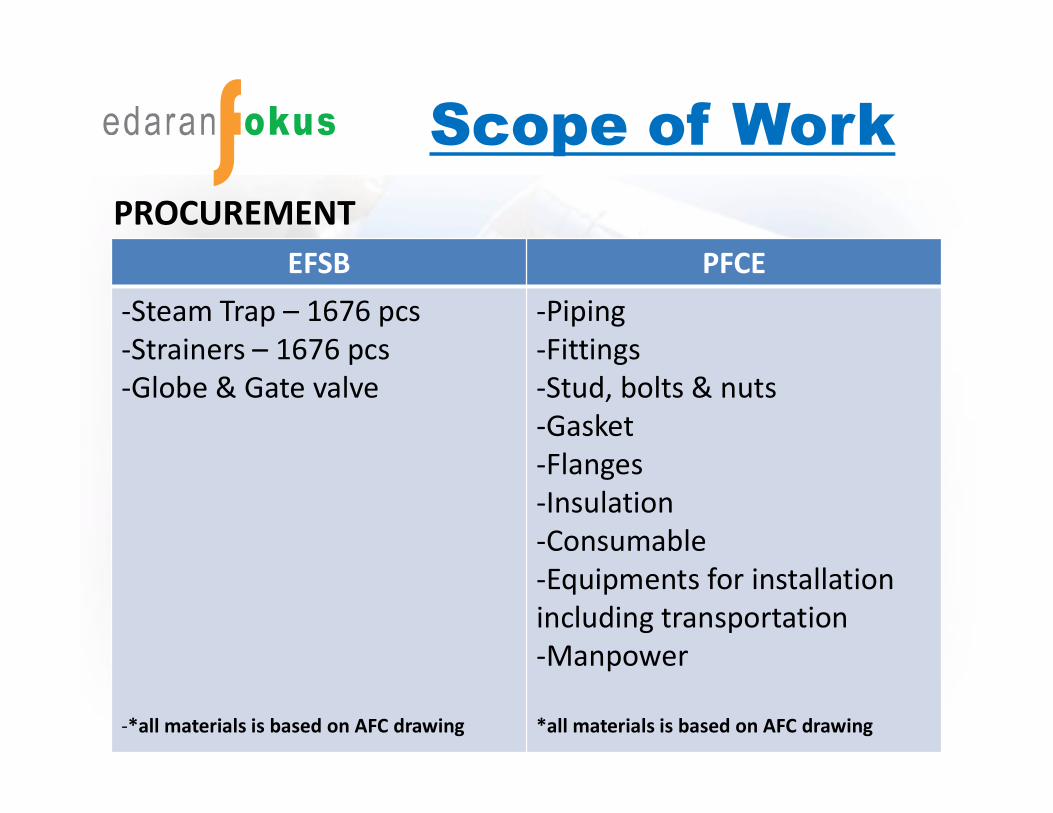
Scope of WorkPROCUREMENT
EFSB PFCE-Steam Trap – 1676 pcs-Strainers – 1676 pcs-Globe & Gate valve
-*all materials is based on AFC drawing
-Piping-Fittings -Stud, bolts & nuts-Gasket-Flanges-Insulation-Consumable-Equipments for installation including transportation-Manpower
*all materials is based on AFC drawing
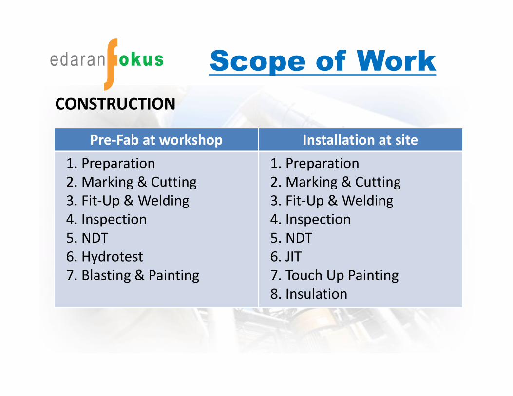
Scope of WorkCONSTRUCTION
-g
Pre-Fab at workshop Installation at site1. Preparation2. Marking & Cutting3. Fit-Up & Welding4. Inspection5. NDT6. Hydrotest7. Blasting & Painting
1. Preparation2. Marking & Cutting3. Fit-Up & Welding4. Inspection5. NDT6. JIT7. Touch Up Painting8. Insulation
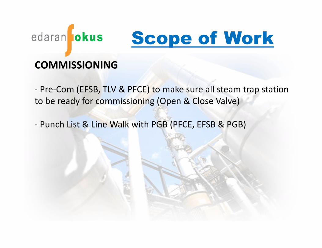
Scope of WorkCOMMISSIONING
- Pre-Com (EFSB, TLV & PFCE) to make sure all steam trap station to be ready for commissioning (Open & Close Valve)
- Punch List & Line Walk with PGB (PFCE, EFSB & PGB)
Fundamentals of Steam Trap
WHAT IS STEAM TRAP?
- Steam traps are a type of automatic valve that filters out condensate (i.e. condensed steam) and non-condensable gases such as air without letting steam escape.
- In industry, steam is used regularly for heating or as a driving force for mechanical power. Steam traps are used in such applications to ensure that steam is not wasted.

Fundamentals of Steam Trap
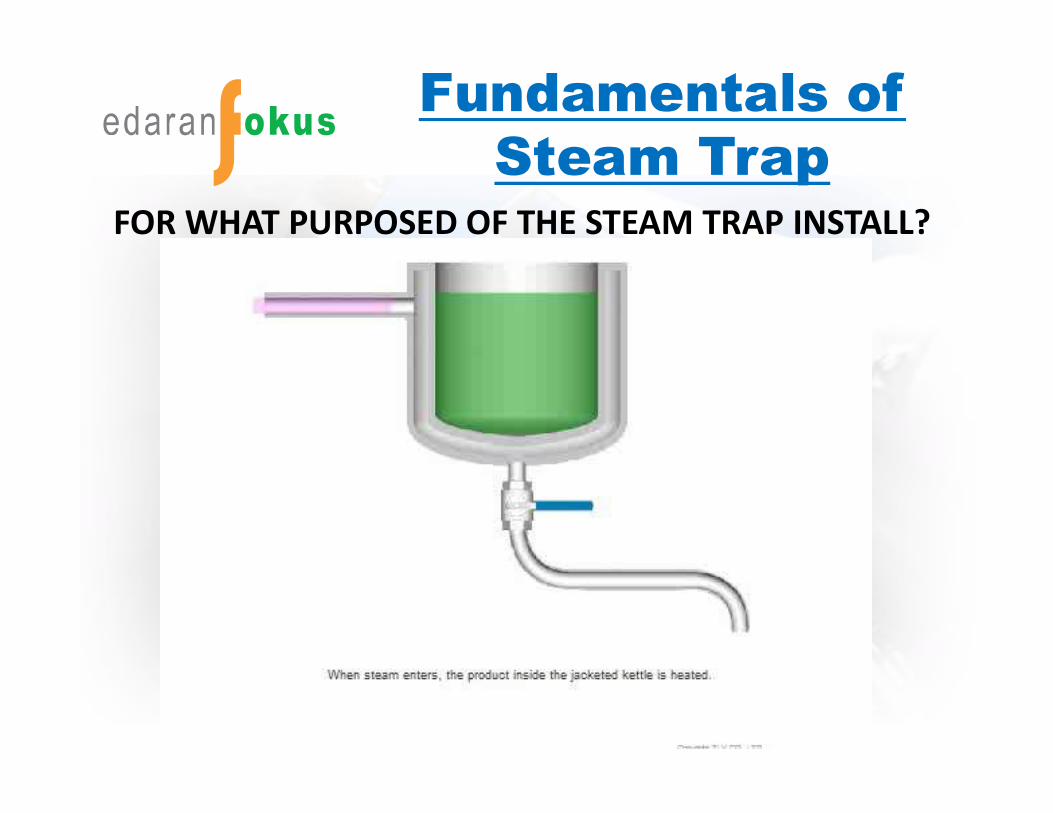
Fundamentals of Steam Trap
FOR WHAT PURPOSED OF THE STEAM TRAP INSTALL?
Fundamentals of Steam Trap
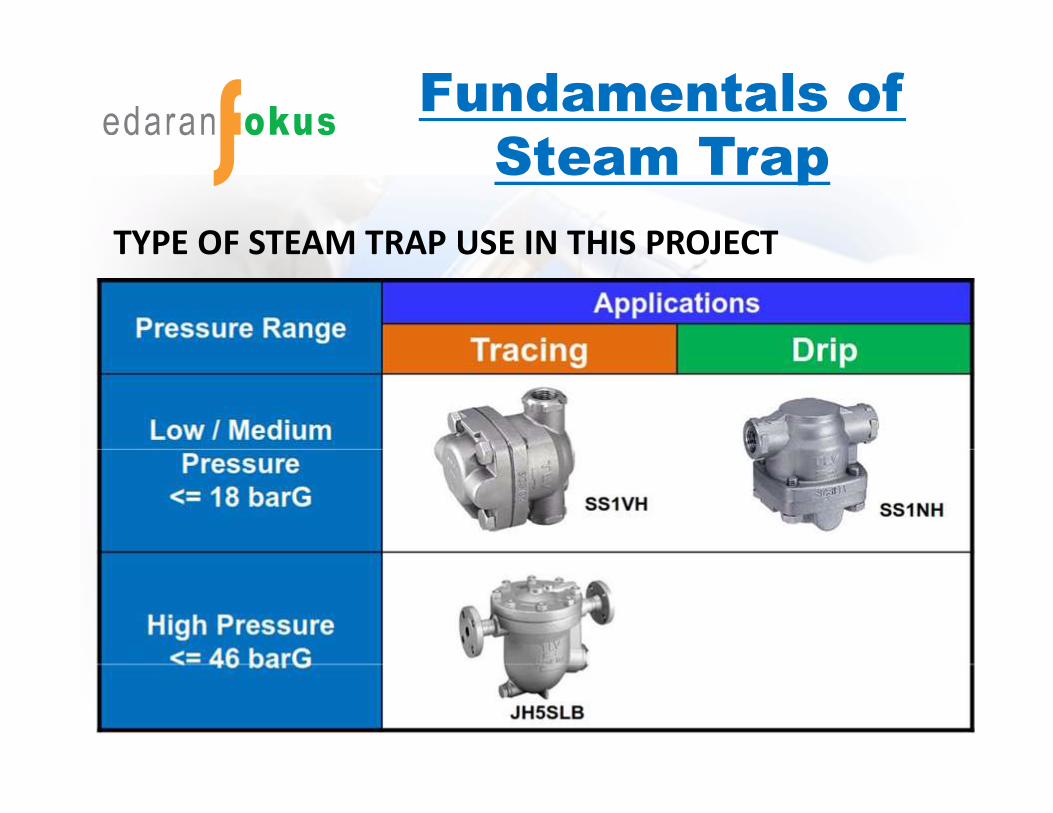
TYPE OF STEAM TRAP USE IN THIS PROJECT
Fundamentals of Steam Trap
TRACING & DRIPPING
Tracing - a process that is designed to prevent heat loss as Product are flowing through a piping system.
Dripping - a process that is designed to remove condensate from the system. When Steam travelling from point A to point B, energy will loss and become condensate. This condensate have to be removed to prevent water hammering.
Fundamentals of Strainer
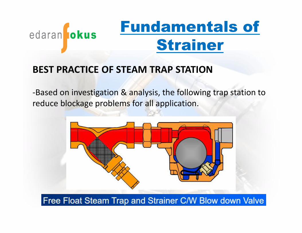
BEST PRACTICE OF STEAM TRAP STATION
-Based on investigation & analysis, the following trap station to reduce blockage problems for all application.
Fundamentals of Valve
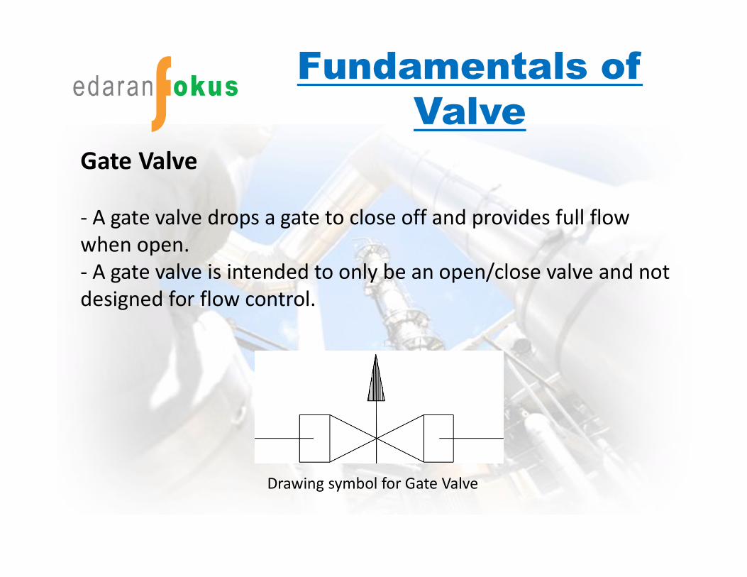
Gate Valve
- A gate valve drops a gate to close off and provides full flow when open.- A gate valve is intended to only be an open/close valve and not designed for flow control.
Drawing symbol for Gate Valve
Fundamentals of Valve
Fundamentals of Valve
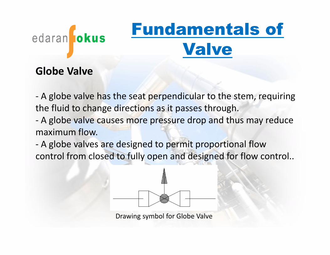
Globe Valve
- A globe valve has the seat perpendicular to the stem, requiring the fluid to change directions as it passes through. - A globe valve causes more pressure drop and thus may reduce maximum flow.- A globe valves are designed to permit proportional flow control from closed to fully open and designed for flow control..
Drawing symbol for Globe Valve
Fundamentals of Valve
Fundamentals of Valve
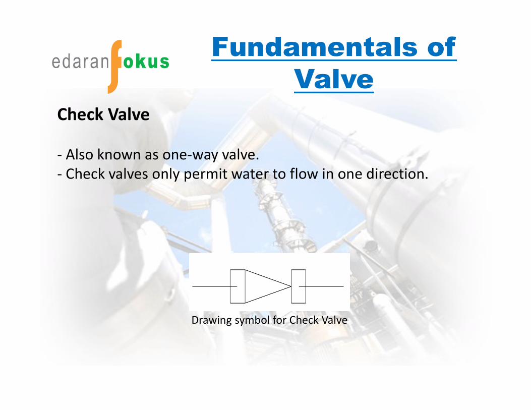
Check Valve
- Also known as one-way valve.- Check valves only permit water to flow in one direction.
Drawing symbol for Check Valve

Fundamentals of Valve
Piping Configuration Design
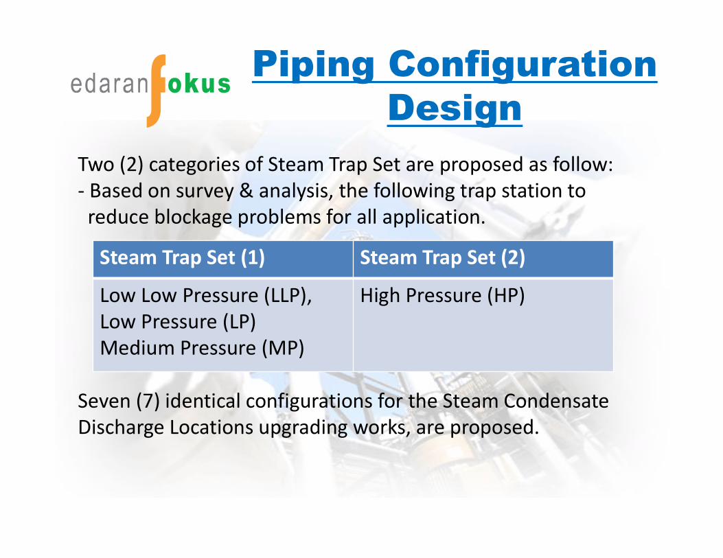
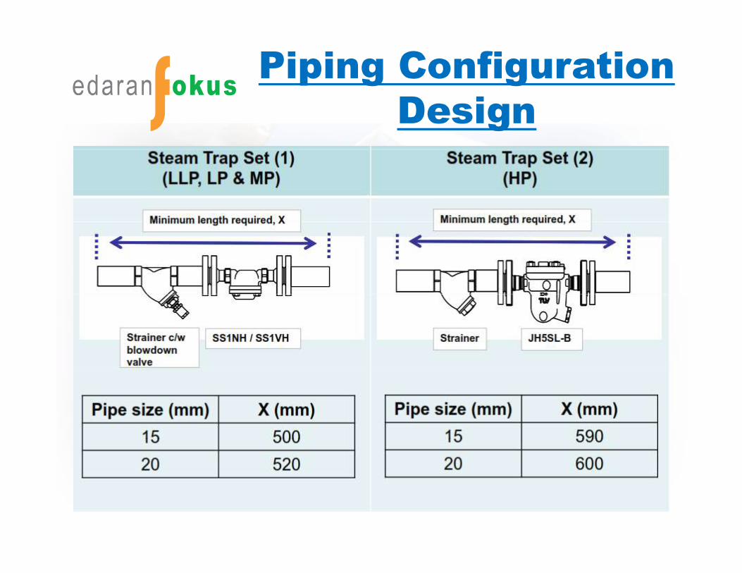
Two (2) categories of Steam Trap Set are proposed as follow:- Based on survey & analysis, the following trap station to reduce blockage problems for all application.
Seven (7) identical configurations for the Steam Condensate Discharge Locations upgrading works, are proposed.
Steam Trap Set (1) Steam Trap Set (2)
Low Low Pressure (LLP), Low Pressure (LP) Medium Pressure (MP)
High Pressure (HP)
Piping Configuration Design

Piping Configuration Design
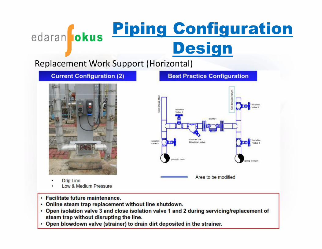
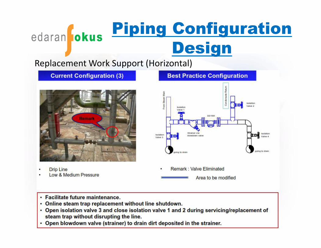
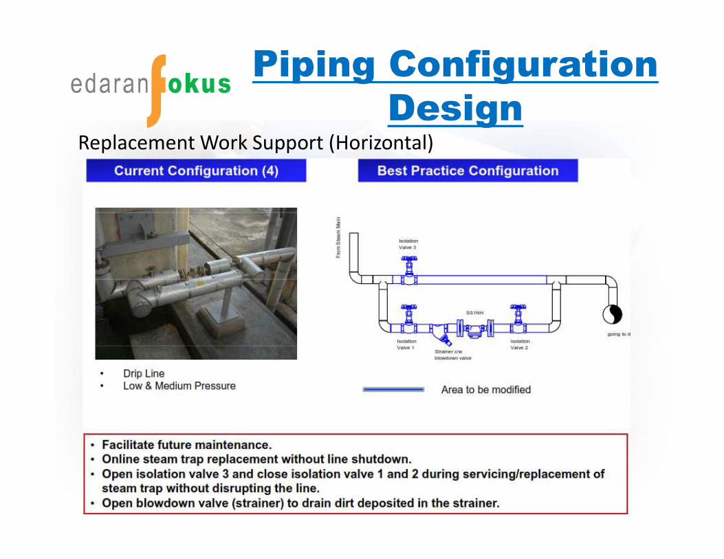
Replacement Work Support (Horizontal)
Piping Configuration Design
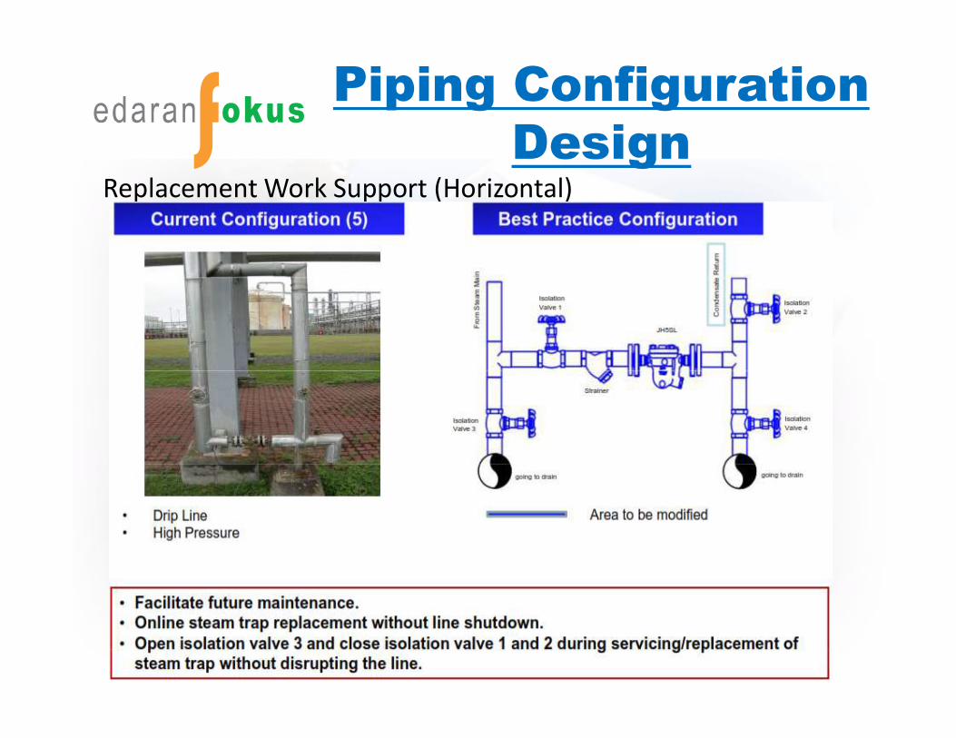
Replacement Work Support (Horizontal)
Piping Configuration Design
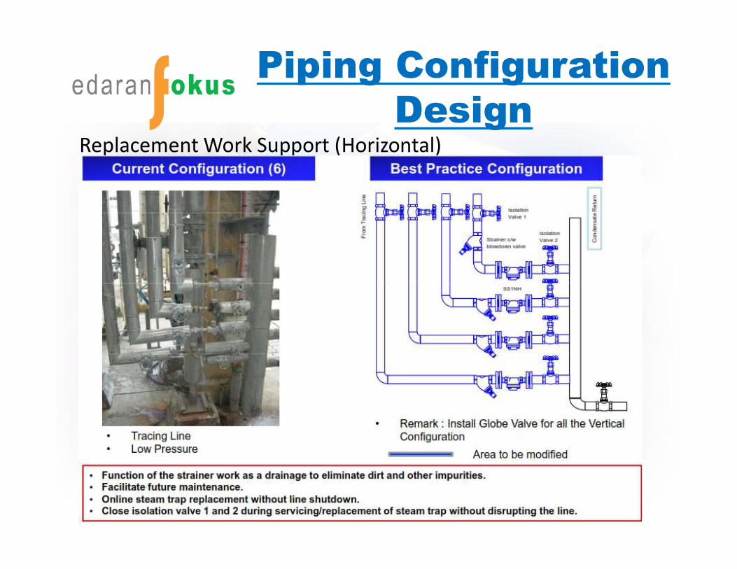
Replacement Work Support (Horizontal)
Piping Configuration Design
Replacement Work Support (Horizontal)
Piping Configuration Design
Replacement Work Support (Horizontal)
Piping Configuration Design
Replacement Work Support (Horizontal)

Piping Configuration Design
Replacement Work Support (Horizontal)
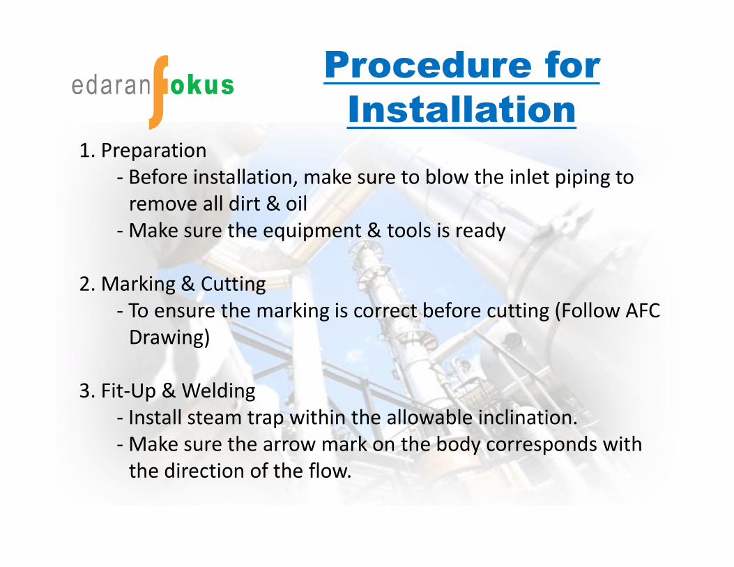
Procedure for Installation
1. Preparation- Before installation, make sure to blow the inlet piping to
remove all dirt & oil- Make sure the equipment & tools is ready
2. Marking & Cutting- To ensure the marking is correct before cutting (Follow AFC
Drawing)
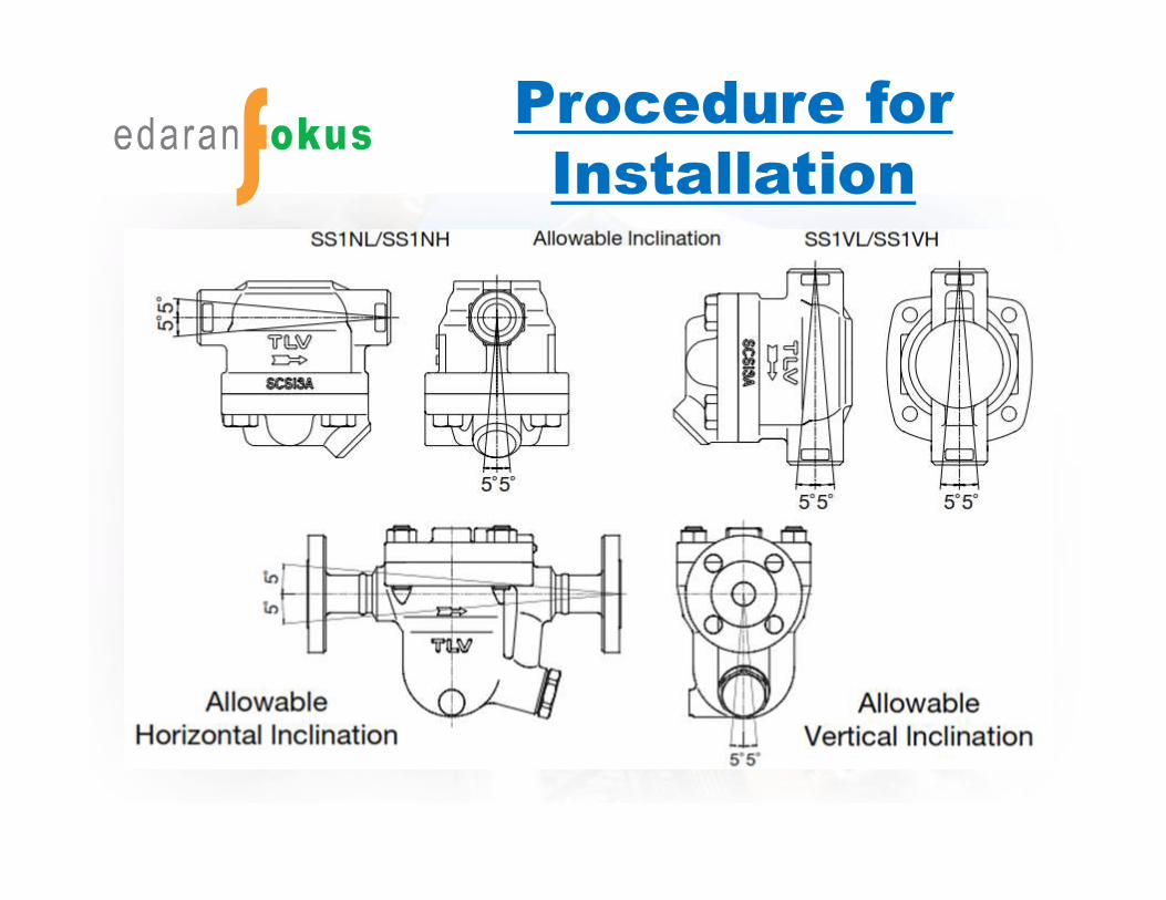
3. Fit-Up & Welding- Install steam trap within the allowable inclination. - Make sure the arrow mark on the body corresponds with
the direction of the flow.
Procedure for Installation
Procedure for Installation
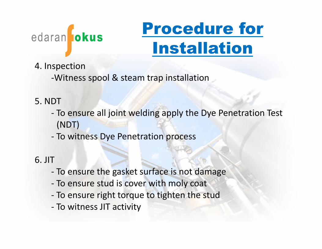
4. Inspection-Witness spool & steam trap installation
5. NDT- To ensure all joint welding apply the Dye Penetration Test
(NDT)- To witness Dye Penetration process
6. JIT- To ensure the gasket surface is not damage- To ensure stud is cover with moly coat- To ensure right torque to tighten the stud- To witness JIT activity
Communication Flow
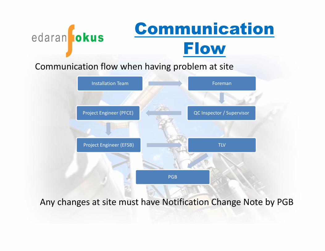
Communication flow when having problem at site
Installation Team Foreman
QC Inspector / SupervisorProject Engineer (PFCE)
Project Engineer (EFSB) TLV
PGB
Any changes at site must have Notification Change Note by PGB

Thanks t


![steam trap performance[1]](https://img.pdfslide.net/doc/110x75/551b18ab4a795911748b45cc/steam-trap-performance1.jpg)