Embed Size (px)
Citation preview
TechnicalManual
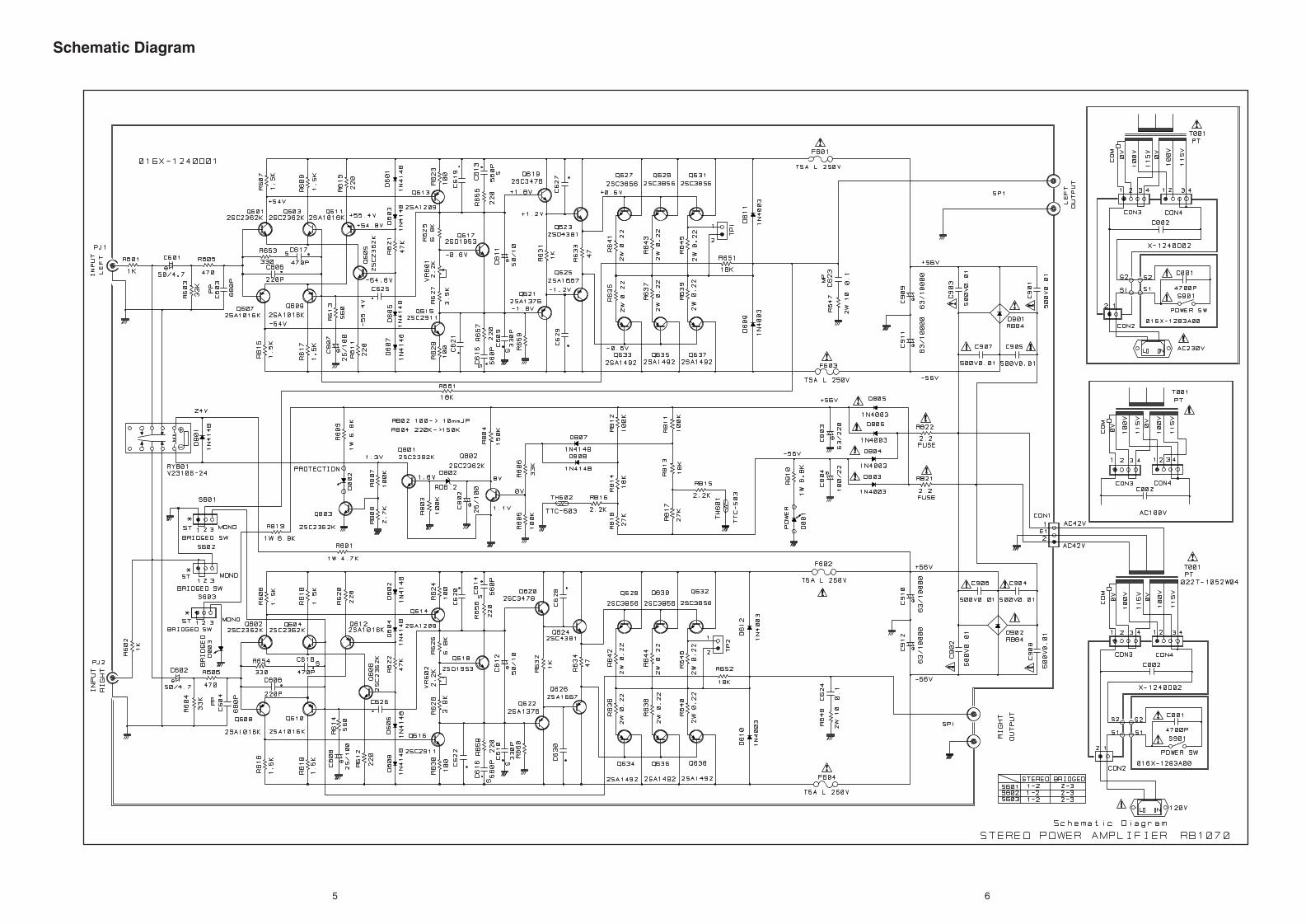
STEREO POWER AMPLIFIER
RB-1070Table of Contents
Specification
Specification......................................1Parts List ...........................................2Adjustment........................................3Case Outlines....................................3PCB Assembly ..................................3~4Schematic Diagram ..........................5~6
Continuous Power Output Stereo Mode 130 watts/ch into 8 ohms (20 - 20 kHz, <0.03% THD)Bridged Mono Power Output 300 watts/ch into 4 ohms (20 - 20 kHz, <0.1% THD)Total Harmonic Distortion <0.03 % (20 Hz : 20 kHz, 8 ohms) Intermodulation Distortion <0.03 % (60 Hz : 7 kHz, 4 : 1) Frequency Response (+0.5 db, -3 db) 4 Hz - 100 kHzDamping Factor (20-20,000 Hz, 8 ohms) 500Speaker Impedance (combined load) 4 ohms minimumSignal to Noise Ratio (IHF A network) 120 dB Input Impedance/Sensitivity 33 k ohms/1.0 voltPower Requirements USA: 115 volts, 60 Hz
Europe: 230 volts, 50 Hz Power Consumption 400 WattsDimensions (W x H x D) 430 x 121 x 350 mm
1615/16 x 43/4 x 133/4 in Weight (net) 11.9 kg/26.25 lb.
SHINSEN-BLD. 4F 10-10 SHINSEN-CHO, SHIBUYA-KU,TOKYO 150-0045, JAPAN
Serial. NO.Beginning
®
Quality Uncompromised
Y-323A-00015C/S-S
2
SYMBOL PARTS NO. DESCRIPTION SYMBOL PARTS NO. DESCRIPTION
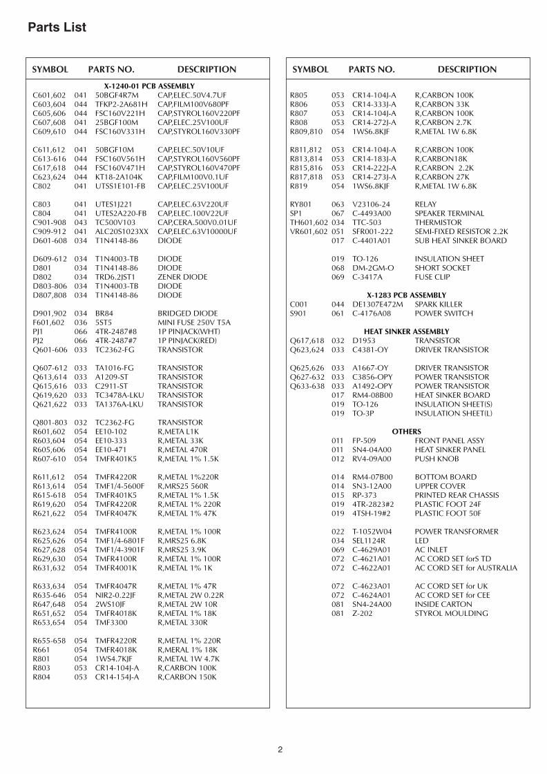
Parts List
X-1240-01 PCB ASSEMBLYC601,602 041 50BGF4R7M CAP,ELEC.50V4.7UFC603,604 044 TFKP2-2A681H CAP,FILM100V680PFC605,606 044 FSC160V221H CAP,STYROL160V220PFC607,608 041 25BGF100M CAP,ELEC.25V100UFC609,610 044 FSC160V331H CAP,STYROL160V330PF
C611,612 041 50BGF10M CAP,ELEC.50V10UFC613-616 044 FSC160V561H CAP,STYROL160V560PFC617,618 044 FSC160V471H CAP,STYROL160V470PFC623,624 044 KT18-2A104K CAP,FILM100V0.1UFC802 041 UTSS1E101-FB CAP,ELEC.25V100UF
C803 041 UTES1J221 CAP,ELEC.63V220UFC804 041 UTES2A220-FB CAP,ELEC.100V22UFC901-908 043 TC500V103 CAP,CERA.500V0.01UFC909-912 041 ALC20S1023XX CAP,ELEC.63V10000UFD601-608 034 T1N4148-86 DIODE
D609-612 034 T1N4003-TB DIODED801 034 T1N4148-86 DIODED802 034 TRD6.2JST1 ZENER DIODED803-806 034 T1N4003-TB DIODED807,808 034 T1N4148-86 DIODE
D901,902 034 BR84 BRIDGED DIODEF601,602 036 5ST5 MINI FUSE 250V T5APJ1 066 4TR-2487#8 1P PINJACK(WHT)PJ2 066 4TR-2487#7 1P PINJACK(RED)Q601-606 033 TC2362-FG TRANSISTOR
Q607-612 033 TA1016-FG TRANSISTORQ613,614 033 A1209-ST TRANSISTORQ615,616 033 C2911-ST TRANSISTORQ619,620 033 TC3478A-LKU TRANSISTORQ621,622 033 TA1376A-LKU TRANSISTOR
Q801-803 032 TC2362-FG TRANSISTORR601,602 054 EE10-102 R,META L1KR603,604 054 EE10-333 R,METAL 33KR605,606 054 EE10-471 R,METAL 470RR607-610 054 TMFR401K5 R,METAL 1% 1.5K
R611,612 054 TMFR4220R R,METAL 1%220RR613,614 054 TMF1/4-5600F R,MRS25 560RR615-618 054 TMFR401K5 R,METAL 1% 1.5KR619,620 054 TMFR4220R R,METAL 1% 220RR621,622 054 TMFR4047K R,METAL 1% 47K R623,624 054 TMFR4100R R,METAL 1% 100RR625,626 054 TMF1/4-6801F R,MRS25 6.8KR627,628 054 TMF1/4-3901F R,MRS25 3.9KR629,630 054 TMFR4100R R,METAL 1% 100RR631,632 054 TMFR4001K R,METAL 1% 1K
R633,634 054 TMFR4047R R,METAL 1% 47RR635-646 054 NIR2-0.22JF R,METAL 2W 0.22RR647,648 054 2WS10JF R,METAL 2W 10RR651,652 054 TMFR4018K R,METAL 1% 18KR653,654 054 TMF3300 R,METAL 330R
R655-658 054 TMFR4220R R,METAL 1% 220RR661 054 TMFR4018K R,MERAL 1% 18KR801 054 1WS4.7KJF R,METAL 1W 4.7KR803 053 CR14-104J-A R,CARBON 100KR804 053 CR14-154J-A R,CARBON 150K
R805 053 CR14-104J-A R,CARBON 100KR806 053 CR14-333J-A R,CARBON 33KR807 053 CR14-104J-A R,CARBON 100KR808 053 CR14-272J-A R,CARBON 2.7KR809,810 054 1WS6.8KJF R,METAL 1W 6.8K
R811,812 053 CR14-104J-A R,CARBON 100KR813,814 053 CR14-183J-A R,CARBON18KR815,816 053 CR14-222J-A R,CARBON 2.2KR817,818 053 CR14-273J-A R,CARBON 27KR819 054 1WS6.8KJF R,METAL 1W 6.8K
RY801 063 V23106-24 RELAYSP1 067 C-4493A00 SPEAKER TERMINALTH601,602 034 TTC-503 THERMISTORVR601,602 051 SFR001-222 SEMI-FIXED RESISTOR 2.2K
017 C-4401A01 SUB HEAT SINKER BOARD
019 TO-126 INSULATION SHEET068 DM-2GM-O SHORT SOCKET069 C-3417A FUSE CLIP
X-1283 PCB ASSEMBLYC001 044 DE1307E472M SPARK KILLERS901 061 C-4176A08 POWER SWITCH
HEAT SINKER ASSEMBLYQ617,618 032 D1953 TRANSISTORQ623,624 033 C4381-OY DRIVER TRANSISTOR
Q625,626 033 A1667-OY DRIVER TRANSISTORQ627-632 033 C3856-OPY POWER TRANSISTORQ633-638 033 A1492-OPY POWER TRANSISTOR
017 RM4-08B00 HEAT SINKER BOARD019 TO-126 INSULATION SHEET(S)019 TO-3P INSULATION SHEET(L)
OTHERS011 FP-509 FRONT PANEL ASSY011 SN4-04A00 HEAT SINKER PANEL012 RV4-09A00 PUSH KNOB
014 RM4-07B00 BOTTOM BOARD014 SN3-12A00 UPPER COVER015 RP-373 PRINTED REAR CHASSIS019 4TR-2823#2 PLASTIC FOOT 24F019 4TSH-19#2 PLASTIC FOOT 50F
022 T-1052W04 POWER TRANSFORMER034 SEL1124R LED069 C-4629A01 AC INLET072 C-4621A01 AC CORD SET forS TD072 C-4622A01 AC CORD SET for AUSTRALIA
072 C-4623A01 AC CORD SET for UK072 C-4624A01 AC CORD SET for CEE081 SN4-24A00 INSIDE CARTON081 Z-202 STYROL MOULDING
3 4
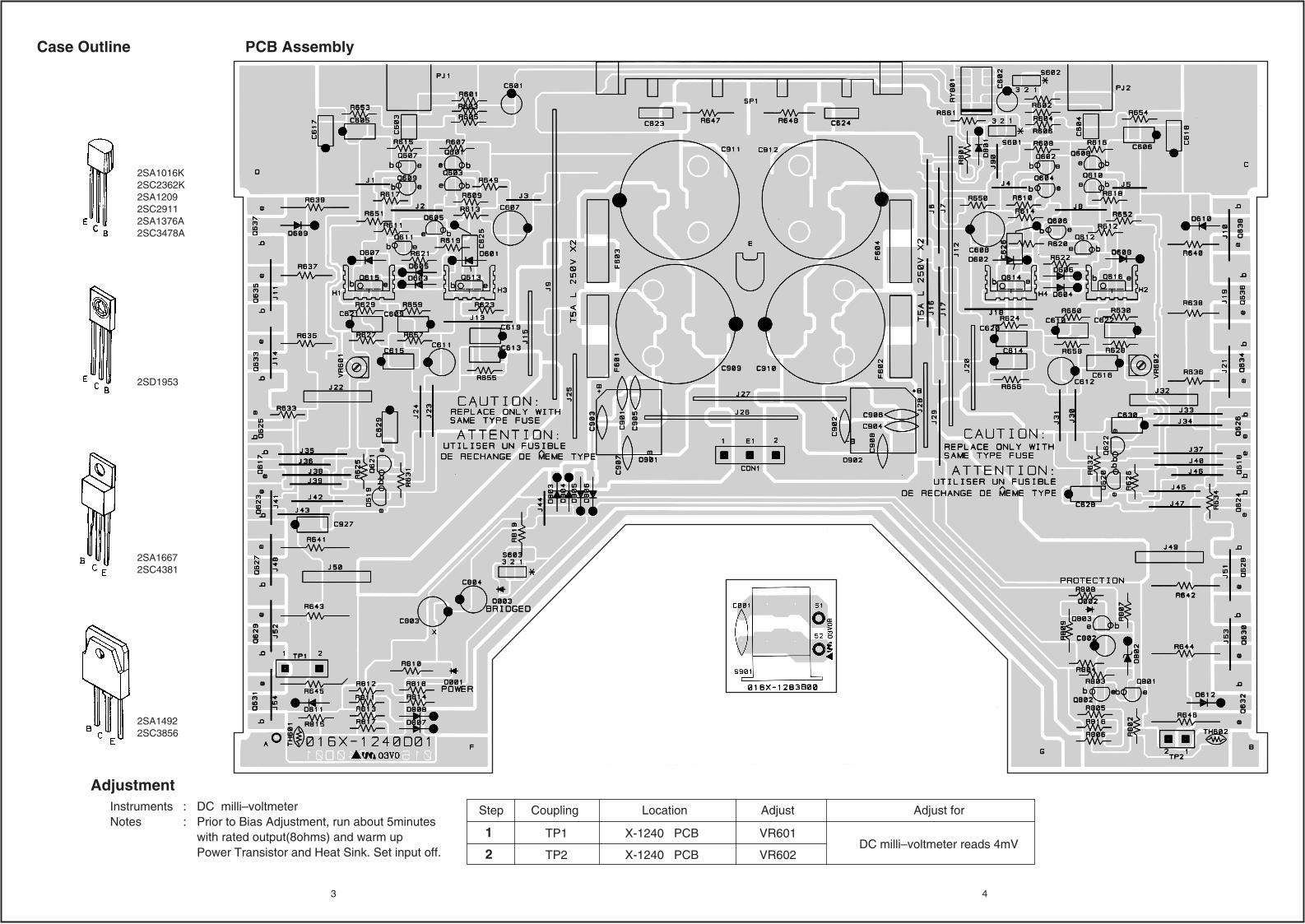
2SA1016K2SC2362K2SA12092SC29112SA1376A2SC3478A
2SD1953
2SA16672SC4381
2SA14922SC3856
Instruments : DC milli–voltmeterNotes : Prior to Bias Adjustment, run about 5minutes with rated output(8ohms) and warm up
Power Transistor and Heat Sink. Set input off.
Adjustment
Step
TP1
TP2
X-1240 PCB VR601
VR602X-1240 PCB
1
2
Coupling Location Adjust forAdjust
DC milli–voltmeter reads 4mV
PCB AssemblyCase Outline
5 6
Schematic Diagram
Y-327A-V1-00121M/S-S
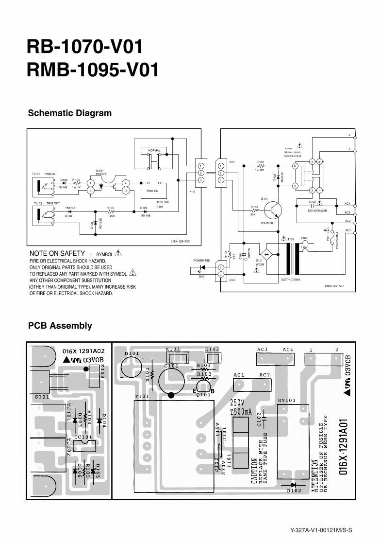
PCB Assembly
Schematic Diagram
RB-1070-V01RMB-1095-V01
R
R
R
R
R
NOTE ON SAFETY : SYMBOL FIRE OR ELECTRICAL SHOCK HAZARD.ONLY ORIGINAL PARTS SHOULD BE USEDTO REPLACED ANY PART MARKED WITH SYMBOLANY OTHER COMPONENT SUBSTITUTION(OTHER THAN ORIGINAL TYPE), MANY INCREASE RISKOF FIRE OR ELECTRICAL SHOCK HAZARD.
1
2 3
4
1
2
3
4
5
61
2
3
1
2
3
1
2
3
2
1
3
2
1
S101
IC101
104
RY101
D103
D106
D10
5
105 D104
K101 101
102
K103
Q101
D10
2
D101
C10
1
F10
1
C102
103
D001K102
TRIG SW
PC817B
1W 1K
OZ-SH-112LM1
1N4148
1N4148
RD
12JS
220 1N4148
1w 120
33K
2SC3708
1N41
48
W02M
25V
470
DE1307E472M
1.5K
POWER IND
TRIG ON
NORMAL
OM1-SS-212LM
T101
250V
T50
0MA
AC1
AC2
AC3
AC4
1
2
TJ101
TJ102
TRIG IN
TRIG OUT
022T-1075N01
230V
115V
016X-1291A01
016X-1291A02
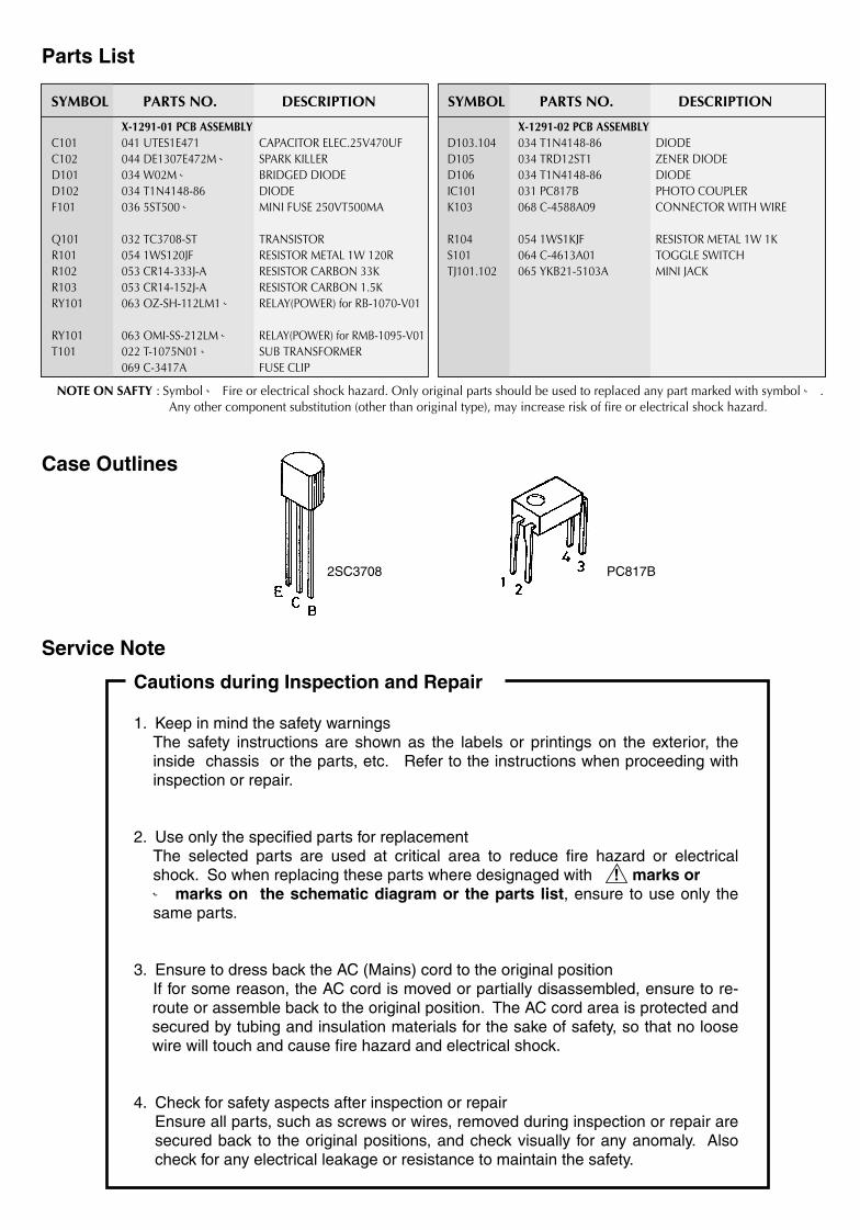
Parts List
C101C102D101D102F101
Q101R101R102R103RY101
RY101T101
D103.104D105D106IC101K103
R104S101TJ101.102
X-1291-01 PCB ASSEMBLY041 UTES1E471044 DE1307E472M ※034 W02M ※034 T1N4148-86036 5ST500 ※
032 TC3708-ST054 1WS120JF 053 CR14-333J-A053 CR14-152J-A063 OZ-SH-112LM1 ※
063 OMI-SS-212LM ※022 T-1075N01 ※069 C-3417A
CAPACITOR ELEC.25V470UFSPARK KILLERBRIDGED DIODEDIODEMINI FUSE 250VT500MA
TRANSISTORRESISTOR METAL 1W 120RRESISTOR CARBON 33KRESISTOR CARBON 1.5KRELAY(POWER) for RB-1070-V01
RELAY(POWER) for RMB-1095-V01SUB TRANSFORMERFUSE CLIP
X-1291-02 PCB ASSEMBLY034 T1N4148-86034 TRD12ST1034 T1N4148-86031 PC817B068 C-4588A09
054 1WS1KJF064 C-4613A01065 YKB21-5103A
DIODEZENER DIODEDIODEPHOTO COUPLERCONNECTOR WITH WIRE
RESISTOR METAL 1W 1KTOGGLE SWITCHMINI JACK
SYMBOL PARTS NO. DESCRIPTION SYMBOL PARTS NO. DESCRIPTION
NOTE ON SAFTY : Symbol ※ Fire or electrical shock hazard. Only original parts should be used to replaced any part marked with symbol ※ .Any other component substitution (other than original type), may increase risk of fire or electrical shock hazard.
�
Case Outlines
Service Note
Cautions during Inspection and Repair
1. Keep in mind the safety warningsThe safety instructions are shown as the labels or printings on the exterior, the inside chassis or the parts, etc. Refer to the instructions when proceeding with inspection or repair.
2. Use only the specified parts for replacementThe selected parts are used at critical area to reduce fire hazard or electrical shock. So when replacing these parts where designaged with marks or ※ marks on the schematic diagram or the parts list, ensure to use only the same parts.
3. Ensure to dress back the AC (Mains) cord to the original positionIf for some reason, the AC cord is moved or partially disassembled, ensure to re-route or assemble back to the original position. The AC cord area is protected and secured by tubing and insulation materials for the sake of safety, so that no loose wire will touch and cause fire hazard and electrical shock.
4. Check for safety aspects after inspection or repairEnsure all parts, such as screws or wires, removed during inspection or repair are secured back to the original positions, and check visually for any anomaly. Also check for any electrical leakage or resistance to maintain the safety.
2SC3708 PC817B


![Active Subwoofer System SB-WA720PP - Philips d559 b0aack000004 diode [m] d560 b0aack000004 diode [m] d561 b0ba01200008 diode [m] d562 b0aack000004 diode [m] d563 b0ba01900005 diode](https://img.pdfslide.net/doc/110x75/5baed8c209d3f290738dc283/active-subwoofer-system-sb-wa720pp-philips-d559-b0aack000004-diode-m-d560-b0aack000004.jpg)
![Chapter 1: Diode circuits vtusolutionvtusolution.in/uploads/9/9/9/3/99939970/analog_electronic[15ec32].pdf · Chapter 1: Diode circuits ... • Diode testing • Zener diode • Diode](https://img.pdfslide.net/doc/110x75/5aedefea7f8b9a9031905d54/chapter-1-diode-circuits-vt-15ec32pdfchapter-1-diode-circuits-diode.jpg)