Embed Size (px)
Citation preview

-+
+
Architectural Engineering 2012 Senior Thesis
A d v i s o r : D r . R o b e r t L e i c h t
Oct. 12, 2012
Technical Assignment 2
Reston Station Phase 1 Garage | Reston, VA
Jonathan A Fisher

TECHNICAL ASSIGNMENT 2 2012
Jon Fisher | Technical Assignment 1 | September 21, 2012 Page 1
Executive Summary Reston Station Phase 1 Garage is the first of many new building projects in Reston to usher
in the arrival of the Metro Rail Silver Line Expansion in early 2014. The Wiehle Avenue stop on
the new route running from downtown Washington D.C to Dulles International Airport lies
adjacent to the new Reston Station project being built by Comstock Partners Limited and Fairfax
County Virginia (a public-private partnership). The project consists of a 7 level, 1.3 million square
foot underground garage that will one day be the foundation for 3 office buildings, a 700 unit
apartment building, and a 20 story hotel.
Technical Assignment Two explores both project schedule and cost at a deeper level than
what was presented in Technical Assignment One. In addition, the project’s general conditions
costs are evaluated, the ways that BIM was utilized on site are reviewed and critiqued, and the
biggest constructability issues of the project are examined.
Project schedule and duration are extremely important at Reston Station due to the soon
arrival of the metro silver line. Sequencing is overviewed and highlights of the key issues on the
critical path are presented in the first section of this report. Concrete design delays must be
resolved in order for the team to maintain the project delivery schedule.
Following the schedule analysis a detailed structural system estimate is presented of a 30
foot wide cross section of the parking structure. The concrete structure was divided into
individual components for estimating purposes consisting of the slab on grade, footers, columns,
elevated slabs, walls and beams. The estimate is then compared to the project’s actual budget
where significant discrepancies are examined.
In addition to the structure being estimated, the general conditions of the project were
also estimated and examined using data provided by the general contractor. Costs incurred by
the general contractor relating to staffing, insurance, temporary utilities, and temporary facilities
were quantified. Also, some typical general condition items that were included in subcontractor
contracts are discussed.
The uses of Building Information Modeling are examined in the next section. Many of the
concepts discussed within this portion of the document are covered at length in the publication
by The Pennsylvania State University’s Computer Integrated Construction Research Program
titled “BIM Project Execution Planning Guide. Both the ways that the project team at Reston
Station uses BIM in construction and the potential ways they could benefit from its use are
discussed here.
At the conclusion of this report the three biggest issues of constructability are discussed.
They include the design delays from the Architect and engineers, the limited equipment staging
areas, and the halted progress with complex sequences like sprinkler pipe installation. From this
section some of the key areas for improvement and detailed analysis will be apparent for future
research and consideration.

TECHNICAL ASSIGNMENT 2 2012
Jon Fisher | Technical Assignment 1 | September 21, 2012 Page 2
Table of Contents Executive Summary ................................................................................................................................ 1
Detailed Project Schedule ..................................................................................................................... 3
Detailed Estimate of Concrete Structure ............................................................................................. 5
Estimate of General Conditions ............................................................................................................ 7
Building Information Modeling Implementation ................................................................................ 9
Constructability Issues ......................................................................................................................... 11
Detailed Project Schedule .......................................................................................... 13 APPENDIX A -
Structural System Quantity Takeoff ........................................................................ 19 APPENDIX B-1 -
Detailed Structural Estimate .................................................................................. 25 APPENDIX B-2 -
General Conditions Details ....................................................................................... 27 APPENDIX C -
Building Information Modeling Goals Worksheet ................................................ 29 APPENDIX D-1 -
Building Information Modeling Uses Worksheet .................................................. 31 APPENDIX D-2 -
Building Information Modeling Process Map ....................................................... 33 APPENDIX D-3 -

TECHNICAL ASSIGNMENT 2 2012
Jon Fisher | Technical Assignment 1 | September 21, 2012 Page 3
Phase/Task Start Date End Date Duration
Procurment 1/17/2011 5/31/2012 359
Excavation 4/25/2011 1/3/2012 182
Concrete 6/14/2011 7/12/2012 283
MEP & Finishes 2/14/2012 2/18/2013 265
Project Closeout 2/19/2013 7/17/2013 107
Reston Station Schedule Highlight
Detailed Project Schedule The schedule at Reston Station and an on-time delivery date is vital because the parking
spaces must be available for Reston area commuters prior to the startup of the new Metrorail
Silver Line from Washington DC to Dulles Airport. The design and construction schedules were
developed for over a year prior to the start of construction in April of 2011. The fully detailed
baseline schedule for the project consists of nearly 1200 activities but a more condensed version is
available in APPENDIX A of this report. Below Figure 1 shows a summary of the key phases of the
schedule.
Preconstruction services began early in 2010 and several schedules and estimates were
produced for early analysis. One of the biggest challenges in this period of time was determining
the best strategy to construct such a large project and remove the 600,000 cubic yards of soil
required. To increase the benefits of fast-tracking the construction of the garage, design was only
completed to a stage required to receive preliminary permits up to the G4 level of the garage
before construction began.
The date for the Notice to Proceed on the project was April 18th, 2011. One benefit of the
negotiated GMP contract with the contractor is that the procurement for sheeting and shoring
could be done prior to the formal notice to proceed so that excavation could be started as soon as
possible on site. The excavation of the site was the first major activity that sits on the critical path
of the overall project. With a plan area the size of 4 football fields and a depth of over 70 feet, the
excavation took an approximate 10 months to complete. Shortly after the first excavations
reached subgrade depth the foundations for tower cranes 1 and 2 were constructed because
utilizing the tower cranes as early as possible helped reduce traffic and delivery burdens for
concrete delivery.
Fortunately due to the scale of excavation there was adequate room to begin concrete
construction of the foundations and lower level slabs in the western half of the garage while soils
were still being removed from the east side. The rest of the project schedule follows this same
division between east and west halves of the building to maximize crew productivity and space
utilization. Critical path analysis shows that most of the critical activities of the project occur
within the eastern octants of the project. This makes sense because the last finishes at the
conclusion of the project will be in the eastern portions of the building. A diagram of the
construction sequence and progression through the building can be seen below in Figure 2.
Figure 1

TECHNICAL ASSIGNMENT 2 2012
Jon Fisher | Technical Assignment 1 | September 21, 2012 Page 4
Concrete placement was scheduled to
occur during 30% of the entire duration of the
project. Given the scale of the concrete
structure and the significance it has on the
project schedule a lot of effort was taken to
ensure concrete progress keeps up with the rest
of the project. The design delays mentioned in
the first technical assignment and further
analyzed in the constructability issue of this
report has put the concrete schedule in serious
jeopardy. This is especially true in regards to
the buildings east structure; a delay in the G
and H octants (the last areas to be poured) could result in a postponed final delivery date if
schedule delays cannot be made up elsewhere.
The final inspections and punch list activities are scheduled to take almost 4 months at
the end of the construction process. Final cleaning of the garage, commissioning of the MEP
systems, punch listing, and project closeout documentation all occur at this time and the final
date for substantial completion is July 17th of 2013. Arrival of the Silver Line Metrorail expansion is
schedule for early 2014 but Fairfax County is eager to open the garage’s bus terminal and collect
revenue from parking spaces prior to that date.
Figure 2

TECHNICAL ASSIGNMENT 2 2012
Jon Fisher | Technical Assignment 1 | September 21, 2012 Page 5
Detailed Estimate of Concrete Structure The Reston Station underground
garage project is almost exclusively a
concrete structure. Even the limited
amount of steel beams in the elephant
stand and “super columns” is encased in
concrete. The structural system is a two-
way slab with drop panels at the columns.
In order to analyze the cost of the
structure, a cross section through the
entire width of the building and between
column lines 4 and 5 was estimated in
detail. Included within this estimate were
the spread footings, slab on grade,
columns, elevated slabs, walls, and beams. A detailed quantity takeoff can be found in
APPENDIX B-1 and detailed cost estimate can be found in APPENDIX B-2. All unit cost data was
retrieved from RS Means Construction Cost Data 2013.
Foundation
The foundation system is made up of spread footings at the base of every column. These
footings are square and range from 4.5 ft2 to 12.5 ft2 and can have depths up to 78 inches. Normal
weight 6000psi concrete is formed by built-on-site formwork and reinforced with uncoated rebar.
At the perimeter of the building an additional footer connects the edge column footers creating
the same effect of a strip footing all the way around the foundation. These were priced in similar
fashion as the square footings with slight adjustments to find appropriate dimensions.
Slabs
The two-way reinforced slabs of the project have a typical depth of 10 inches but drop
panels increase depths at columns typically by 4.5” or in some cases 8”. The reinforcing steel of
each slab is closely related to slab thickness. In each floor, typical weight of reinforcing was
determined per square foot of slab and extrapolated to incorporate the entire floor system. It is
important to note that epoxy coated rebar was utilized in all of the top reinforcing of the slabs to
protect against corrosion for vehicle tire salts. All slabs were made from 5000 psi normal weight
concrete with a mid-grade plasticizer.
Columns The quantities related to columns were taken from the column schedule of the project
drawings. All columns were reinforced by #11 bars and formed on four sides. Column concrete
strength varied in many columns but an average was assumed for each column in order to
simplify cost estimation.
Figure 3 – Area Analyzed In Detailed Estimate

TECHNICAL ASSIGNMENT 2 2012
Jon Fisher | Technical Assignment 1 | September 21, 2012 Page 6
estimated cost actual cost
Foundations $3,726,410.81 3,000,000.00
Slab on Grade $685,582.29 1,200,000.00
columns $15,693,572.20 3,500,000.00
elevated decks $23,990,507.97 25,000,000.00
Cost Comparison Summary
Item Estimated Price % of Estimate
Fomwork $1,119,331 48%
Reinforcing Steel (uncoated) $410,057 17%
Reinforcing Steel (epoxy) $120,613 5%
Welded Wire Fabric $4,242 0%
Normal Weight Concrete $700,462 30%
Cost by Master Format
Adjustments
Once quantities were determined and cost data was incorporated, several adjustments
were required to more accurately represent the real cost of construction. The first adjustment to
the raw cost estimate is the need for appropriate taxes to be assigned to material costs. The
typical sales tax of 5% is the state of Virginia was used and increased the cost of construction by
approximately $660,000. After tax was incorporated, the location index for Fairfax, Virginia was
used to scale the cost to regional implications on the price. The RS Means index for Fairfax is .92
for the 2013 of the cost data and the construction cost was reduced by over $240,000.
Results The final cost for the 30’ wide
cross section of the concrete structure
was calculated to be $2,774,000. This
cost, when extrapolated to include the
entire width of the structure would result
in a final cost of $55,480,000. The
approximate worth of the actual concrete
contract is approximately $35 million.
This gives an error of over $20 million. A
few factors likely played into the cause of
this large difference. First, the placement
method in RS Means does not include an
onsite batch plant. The cost savings
resulting from the lack of concrete delivery by truck could be very significant. Also, the
assumption was made that forms were used once each in construction for simplicity of the
estimate but in reality a single form on site is probably used between 3 and 4 times. A further
comparison of estimated values versus the real worth of components can be seen in figure 5.
Figure 6 – Cost Comparison
Figure 4 - Relative Materformat Cost
Figure 5 - Master Format Table of Costs

TECHNICAL ASSIGNMENT 2 2012
Jon Fisher | Technical Assignment 1 | September 21, 2012 Page 7
CategoryEstimated
CostCost per Month
% of General
Condidtions
Management & Staffing $2,252,270 $81,017 52%
Insurance & Bonding $1,285,039 $46,224 30%
Temporary Utilities $449,530 $16,170 10%
Temporary Equipment & Facilities $317,704 $11,428 7%
Totals $4,304,543 $154,840
General Conditions Summary
Estimate of General Conditions The information provided in this portion of the report was provided by DAVIS Construction
and some information has been altered to protect project financial data.
As with every construction project, Reston Station has needs for supporting facilities,
utilities, insurance & bonding, and personnel which are all known collectively as general
conditions. A full estimate of the general conditions has been produced using data provided by
the general contractor and supplemented by RS Means Construction Cost Data 2013. Monthly
costs of facilities, utilities, and personnel are based on a project duration of 28 months. The total
cost of the general conditions on the project amounts to $4,300,00. A summary of the general
conditions costs is provided below in figure 7 and a complete breakdown of individual costs can
be found in APPEDIX C of this report.
The most significant contribution
to the cost of the general conditions is the
cost of the project staff which accounts for
52% of the total cost. A very skilled and
talented staff has been selected by DAVIS
Construction to lead this project. In
addition to the project managers and
superintendents, DAVIS incorporates the
services of several other support
departments within the company. These
support services include a project
scheduler, an administrative assistant, a
project accountant, and a safety manager.
As a result of their investment in the quality
of their project team, the general contractor
has demonstrated strong leadership amongst the other companies involved in the construction of
Reston Station.
Figure 7 - General Conditions Summary
Figure 8 - General Conditions Illustration

TECHNICAL ASSIGNMENT 2 2012
Jon Fisher | Technical Assignment 1 | September 21, 2012 Page 8
Insurance and Bonding fees are responsible for 30% of the 4.3 million dollar general
conditions cost. These fees are based off a percentage of the total project value and protect both
owner and contractor from various risks associated with construction. The major policies that
makeup this cost include a general liability policy, builders risk insurance, and a payment and
performance bond.
While temporary equipment, facilities, and utilities only account for a combined 17% of
the general contractors general conditions, these two categories of costs are time dependent. In
short, an early finish date saves money on these items while a longer project duration will drive
the costs of these items up. This is important to realize since project schedule is currently a large
concern.
Several items that are typically associated with the general conditions of a construction
project have been excluded from the general contractor’s estimate due to the capability for sub-
contractors to provide those services through their own individual contracts. Some of the most
significant costs transferred to the subcontractor contracts include site fences, cranes & material
hoists, scaffolding, and temporary heating.

TECHNICAL ASSIGNMENT 2 2012
Jon Fisher | Technical Assignment 1 | September 21, 2012 Page 9
Building Information Modeling Implementation Due to the early involvement of the construction manager in the project, there was a great
opportunity for Building Information Modeling (BIM) to be used extensively on the Reston
Station Project. The primary use for BIM in the construction of the garage is clash detection for
the MEP system coordination. While there are several other BIM capabilities that could have
been used in the project, poor owner implementation has caused the project to fail in realizing
these potentials benefits.
The clash detection of the MEP systems is led by the general contractor’s project engineer.
A model of the structural geometries was developed by a 3rd party firm in Autodesk’s REVIT
Architecture. Each subcontractor was then responsible for the creation of a 3 dimensional model
of their respected system. To perform clash detection, a project engineer compiled the base
model along with the mechanical, electrical, plumbing, and fire protection system models in
Autodesk’s Navisworks Manage. Weekly subcontractor coordination meetings were held online
through an internet meeting service. Areas of coordination were separated by floor and wing.
Even though clash detection adds significant value to the construction process, several
additional areas of BIM implementation could have been explored by the project leadership. The
main reason for a lack of full BIM execution planning is the limited knowledge of the Owner
team. Neither Comstock Partners nor Fairfax County has a background in the proper utilization
of Building Information Model technologies leaving the general contractor as the major driver for
its use. A “BIM Champion” is
described in the BIM Project
Execution Planning Guide
(developed by the Computer
Integrated Construction
Research Program at The
Pennsylvania State University)
as a person or group that “takes
time to learn the procedure and
work to help compile the final
BIM plan and also market the
value and necessity of the
process to the other project
team members.”
In the case of Reston Station, the “BIM champion” is the general contractor but the
greatest success with BIM utilization is found when the BIM champion is a group or member
within the owner organization. Even at the GC level BIM utilization was left in the hands of a
single project engineer with many other responsibilities on site which left the full capabilities of
information modeling unrealized on this project. The following section investigates the possible
ways BIM could have been used at Reston Station.
Figure 9 - Clash Detection (Courtesy of Davis Construction)

TECHNICAL ASSIGNMENT 2 2012
Jon Fisher | Technical Assignment 1 | September 21, 2012 Page 10
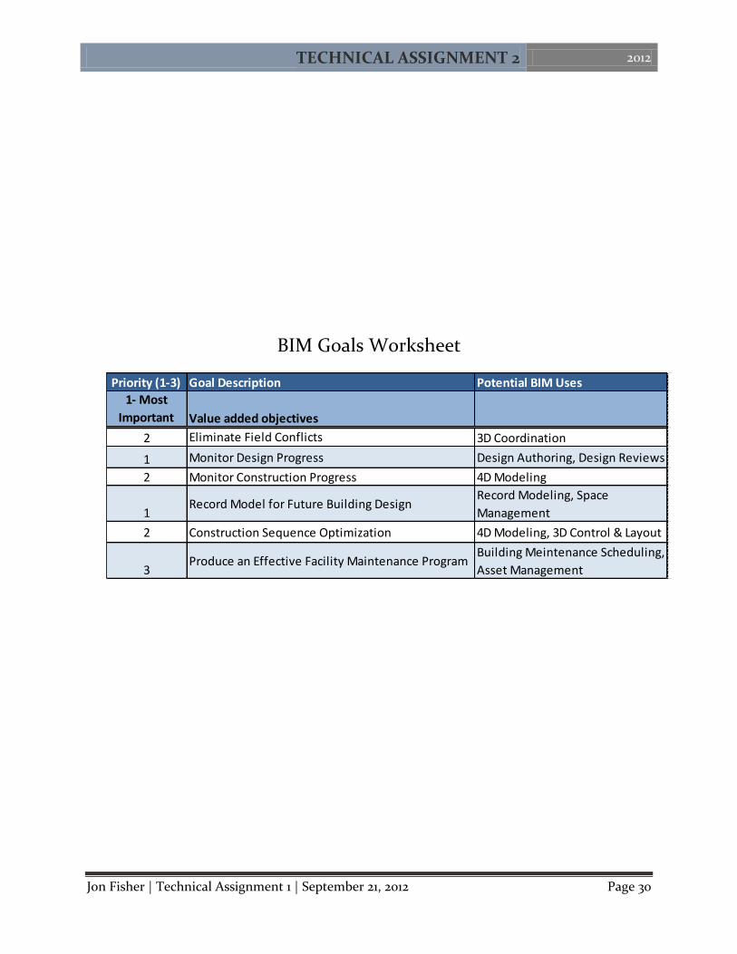
Possible BIM Goals
The entire Reston Station complex could have benefited greatly from a more proactive
approach to the use of Building Information Modeling early in the project development. By
utilizing the concepts presented in the BIM Project Execution Guide, Comstock Partners and
Fairfax County should have developed a few goals early in the project planning process.
The two goals with highest importance to the owner team are monitoring the design
process and obtaining a record model for future use in development. Due to the decision to fast-
track construction of the garage, monitoring design is key to the schedule progress. In addition, a
record model can be useful in the future for integrating the design of the above ground buildings.
Other goals worth pursuing on the project include monitoring the construction progress,
eliminating field conflicts, and optimizing the construction sequence. In addition to tracking the
design progress, following the progression of construction can give a full picture of the status of
the project at any given point in time. In regards to construction sequencing, the complications
with storing equipment on site can be minimized by using visualization tools to communicate
sequence plans to the project team. A full list of possible project goals can be found in Appendix
D-1.
Possible Additional BIM Uses Having established a few specific goals for the BIM implementation on the project, the
individual uses of it can be decided. The uses best suited for Reston Station are 3D Coordination,
4D Modeling, Design Reviews, and Space Management. 4D modeling will help the owner track
construction progress throughout the duration of the project and may even assist the contractor
with trade and work sequencing. In addition to tracking the construction, design can be tracked
using design reviews. These design reviews can also help the owner make decisions on finish
materials and design geometries without a field mockup or physical sample. Finally, space
management and tracking will be useful to Comstock as they will me managing not only a mega
garage, but also 5 large commercial buildings above ground level. In the garage, this space
tracking can be used to monitor public versus private parking areas and temporary closures
during the construction of above grade structures. A full analysis of the selection of these uses
can be seen in Appendix D-2. In addition, a process map of the BIM execution, including
information exchanges for this project, can be found in Appendix D-3.

TECHNICAL ASSIGNMENT 2 2012
Jon Fisher | Technical Assignment 1 | September 21, 2012 Page 11
Constructability Issues In order to successfully complete the Reston Station Phase 1 Garage project several issues
of constructability have to be overcome. The first and most significant is the vast depth and area
of the garage. To remove 600,000 cubic yards of soil from a site is a huge undertaking for a
construction management company and requires both patience and ingenuity on the project
teams part. Aside from the sheer size of the garage project design delays, issues with major
equipment staging and sprinkler pipe painting have all contributed to the challenging
constructability issues at Reston Station.
Design Delays The design delays on the Reston Station project are a result of the decision to fast-track
the construction of the project and the owner’s desire to save money. At the start of construction,
design was only completed to the G4 level and the buildings above ground were still in the
conceptual planning stages. Design has been slow from that point forward due to a lack of
resources in the design team and the structural engineer in particular. At this present time,
construction has progressed to the same point of the design. Concrete placement crew sizes have
begun to diminish as the amount of work to be completed has started to dwindle.
A major issue with the recently released construction change directives at the P1 level is
coordination with the future structures to be constructed on top of the garage. This is most
evident with the alignment of drain penetrations and general dimension discrepancies. The
design of future buildings has been slowed by Comstock’s decision to build the complex one
building at a time. The designs for upper buildings were simply not started early enough to
achieve an adequate level of detail for garage coordination.
As design was accelerated in recent months coordination between the structural engineer,
architect, and MEP engineers has suffered greatly. This issue is significant because errors as
fundamental as the same column being detailed as square in the architectural drawings may be
circular in the structural drawings. This creates a drain on the general contractor’s resources
because of the increased quantity of requests for information in addition to the drain on the
project schedule due to the number of revisions required before a final drawing can be made
ready for construction.
Equipment Staging
Although the Reston Station site is large and has ample space for temporary facilities, the
site lacks space to store major equipment components as they arrive on site prior to installation.
The biggest issues have been encountered with switchgears, intake/exhaust fans, and escalators.
The equipment must be stored properly prior to its installation but the equipment can’t be stored
on any finished traffic coating in order to protect those surfaces as well.
The solution up to this point has been storing materials on unfinished concrete slabs in
the garage covered with weather protection when necessary. Currently over 200 six foot wide by
six foot tall fans sit on the G3 level of the western wing of the garage. This takes up a large

TECHNICAL ASSIGNMENT 2 2012
Jon Fisher | Technical Assignment 1 | September 21, 2012 Page 12
Completed Fire
Protection Design
Fire Sprinkler Permit
Obtained
Inspector Signature to Begin Hydro
Testing
Hydro Tests Completed
Paint Sprinkler
Pipes
amount of space and puts a large load on a slab that is still partially supported by post shores. As
work progresses into the areas being used for storage, a skid steer will need to be used to move all
uninstalled fans to another location. Repeated relocations and work being completed around the
fans greatly increases the likelihood of accidental damage to the equipment before it can be
installed.
Another major piece of equipment being
stored within the garage in addition to the fans is two
escalators. These are some of the most expensive and
specialized pieces of equipment on site. Any damage
to these escalators would be extremely detrimental to
both the cost and schedule of the project. In addition
to being stored in close proximity to ongoing work,
the escalators are also exposed to any inclement
weather. To compound the issue, at the time of
procurement escalator frames and rails were to be
put in place in late September but due to delays the
current expectation is for the escalators to be installed
beginning in early November. An image of the
escalator staging location can be seen in figure 10.
Sprinkler Pipe Given the large amount of floor area in the garage, the fire protection system is one of the
most complex systems in the entire building boasting an incredible 8 miles of exposed sprinkler
piping. The biggest constructability issue with the sprinkler pipes in the garage is a matter of
construction sequencing of tasks. Pipes cannot be painted until hydro tests have been completed
and hydro tests can’t be completed until a sprinkler permit has been obtained. This issue refers
back to design delays and creates a bottle neck effect for other trades in the finish sequencing of
the garage. A visual sequence diagram of the tasks required to paint the sprinkler pipes is
provided below in figure 11.
Figure 10 - Photograph of Escalators in Staging
Figure 11 - Sprinkler Pipe Painting Sequence

TECHNICAL ASSIGNMENT 2 2012
Jon Fisher | Technical Assignment 1 | September 21, 2012 Page 13
APPENDIX A
Detailed Project Schedule

ID Task Name Duration Start Finish
1 Pre Construction 215 days Mon 1/24/11 Fri 11/18/112 Prepare Contract Drawings 93 days Mon 1/24/11 Wed 6/1/113 Permit (Foundation‐G4 Level) 1 day Fri 3/18/11 Fri 3/18/114 Permit (Full Building) 1 day Mon 10/3/11 Mon 10/3/115 Site Utility Relocation 190 days Mon 2/28/11 Fri 11/18/116 Project Procurment 359 days Mon 1/17/11 Thu 5/31/127 Subcontractor Bid & Interview Period 19 days Tue 2/22/11 Fri 3/18/118 Recommendation and Approval of Subcontracts 20 days Mon 3/21/11 Fri 4/15/119 Sheeting & Shoring Procurment 32 days Mon 1/17/11 Tue 3/1/1110 Other Material Procurement 294 days Mon 4/18/11 Thu 5/31/1211 Construction ‐ West (Column Lines 1‐11) 458 days Mon 4/18/11 Wed 1/16/1312 Notice to Proceed 0 days Mon 4/18/11 Mon 4/18/1113 Drill Dewatering Wells (Octant A&B) 10 days Mon 4/18/11 Fri 4/29/1114 Drill Dewatering Wells (Octant C&D) 12 days Mon 5/2/11 Tue 5/17/1115 Install Solider Piles (Oct A&B) 35 days Mon 4/18/11 Fri 6/3/1116 Install Solider Piles (Oct C&D) 59 days Wed 5/4/11 Mon 7/25/1117 Excavation (Oct A&B) 35 days Mon 4/25/11 Fri 6/10/1118 Excavation (Oct C&D) 34 days Mon 6/13/11 Thu 7/28/1119 Install Lagging/Tiebacks (Oct A&B) 33 days Thu 4/28/11 Mon 6/13/1120 Install Lagging/Tiebacks (Oct C&D) 39 days Tue 6/14/11 Fri 8/5/1121 Concrete Footings (Oct A&B) 33 days Tue 6/14/11 Thu 7/28/1122 G7‐G6 Concrete Walls (Oct A&B) 18 days Tue 7/5/11 Thu 7/28/1123 G7‐G6 Concrete Columns (Oct A&B) 19 days Fri 7/8/11 Wed 8/3/1124 G7 Concrete Slab (Oct A&B) 25 days Tue 7/26/11 Mon 8/29/1125 Concrete Footings (Oct C&D) 35 days Fri 7/29/11 Thu 9/15/1126 G7‐G6 Concrete Walls (Oct C&D) 16 days Tue 8/23/11 Tue 9/13/1127 G7‐G6 Concrete Columns (Oct C&D) 17 days Tue 8/23/11 Wed 9/14/1128 G7 Concrete Slab (Oct C&D) 20 days Tue 9/13/11 Mon 10/10/1129 G6 Concrete Slab (Oct A&B) 37 days Tue 8/23/11 Wed 10/12/1130 G6‐G5 Concrete Walls & Columns (Oct A&B) 37 days Wed 8/31/11 Thu 10/20/1131 G6 Concrete Slab (Oct C&D) 24 days Thu 10/13/11 Tue 11/15/1132 G6‐G5 Concrete Walls & Columns (Oct C&D) 24 days Fri 10/21/11 Wed 11/23/1133 G5 Concrete Slab (Oct A&B) 54 days Fri 9/9/11 Wed 11/23/1134 G5‐G4 Concrete Walls & Columns (Oct A&B) 42 days Mon 9/19/11 Tue 11/15/1135 G5 Concrete Slab (Oct C&D) 26 days Mon 10/31/11Mon 12/5/1136 G5‐G4 Concrete Walls & Columns (Oct C&D) 26 days Tue 11/8/11 Tue 12/13/11
Pre Construction
Prepare Contract Drawings
Permit (Foundation‐G4 Level)
Permit (Full Building)
Site Utility Relocation
Project Procurment
Subcontractor Bid & Interview Period
Recommendation and Approval of Subcontracts
Sheeting & Shoring Procurment
Other Material Procurement
Construction ‐ West (Column Lines 1‐11)
Notice to Proceed
Drill Dewatering Wells (Octant A&B)
Drill Dewatering Wells (Octant C&D)
Install Solider Piles (Oct A&B)
Install Solider Piles (Oct C&D)
Excavation (Oct A&B)
Excavation (Oct C&D)
Install Lagging/Tiebacks (Oct A&B)
Install Lagging/Tiebacks (Oct C&D)
Concrete Footings (Oct A&B)
G7‐G6 Concrete Walls (Oct A&B)
G7‐G6 Concrete Columns (Oct A&B)
G7 Concrete Slab (Oct A&B)
Concrete Footings (Oct C&D)
G7‐G6 Concrete Walls (Oct C&D)
G7‐G6 Concrete Columns (Oct C&D)
G7 Concrete Slab (Oct C&D)
G6 Concrete Slab (Oct A&B)
G6‐G5 Concrete Walls & Columns (Oct A&B)
G6 Concrete Slab (Oct C&D)
G6‐G5 Concrete Walls & Columns (Oct C&D)
G5 Concrete Slab (Oct A&B)
G5‐G4 Concrete Walls & Columns (Oct A&B)
G5 Concrete Slab (Oct C&D)
G5‐G4 Concrete Walls & Columns (Oct C&D)
Dec Jan FebMarAprMayJun Jul Aug Sep Oct NovDec Jan FebMarAprMayJun Jul Aug Sep OctNovDec Jan FebMarAprMayJun Jul Aug Sep Oct NovDec Jan FebM010 Qtr 1, 2011 Qtr 2, 2011 Qtr 3, 2011 Qtr 4, 2011 Qtr 1, 2012 Qtr 2, 2012 Qtr 3, 2012 Qtr 4, 2012 Qtr 1, 2013 Qtr 2, 2013 Qtr 3, 2013 Qtr 4, 2013 Qtr 1, 201
Task
Split
Milestone
Summary
Project Summary
External Tasks
External Milestone
Inactive Task
Inactive Milestone
Inactive Summary
Manual Task
Duration‐only
Manual Summary Rollup
Manual Summary
Start‐only
Finish‐only
Deadline
Critical
Critical Split
Progress
Jon FisherReston Station Phase1 GarageReston, VA
Technical Assignment 2 Detailed Project Scedule
Project: detailed scheduleDate: Mon 10/8/12

ID Task Name Duration Start Finish
37 G4 Concrete Slab (Oct A&B) 45 days Tue 10/4/11 Mon 12/5/1138 G4‐G3 Concrete Walls & Columns (Oct A&B) 51 days Wed 10/12/11Wed 12/21/1139 G4 Concrete Slab (Oct C&D) 26 days Tue 12/6/11 Tue 1/10/1240 G4‐G3 Concrete Walls & Columns (Oct C&D) 26 days Wed 12/14/11Wed 1/18/1241 G3 Concrete Slab (Oct A&B) 46 days Fri 10/28/11 Fri 12/30/1142 G3‐G2 Concrete Walls & Columns (Oct A&B) 47 days Mon 11/7/11 Tue 1/10/1243 G3 Concrete Slab (Oct C&D) 24 days Tue 1/3/12 Fri 2/3/1244 G3‐G2 Concrete Walls & Columns (Oct C&D) 24 days Wed 1/11/12 Mon 2/13/1245 G2 Concrete Slab (Oct A&B) 47 days Tue 11/15/11 Wed 1/18/1246 G2‐G1 Concrete Walls & Columns (Oct A&B) 47 days Wed 11/23/11 Thu 1/26/1247 G2 Concrete Slab (Oct C&D) 24 days Thu 1/19/12 Tue 2/21/1248 G2‐G1 Concrete Walls & Columns (Oct C&D) 24 days Fri 1/27/12 Wed 2/29/1249 G1 Concrete Slab (Oct A&B) 39 days Tue 12/13/11 Fri 2/3/1250 G1‐P1 Concrete Walls & Columns (Oct A&B) 46 days Wed 12/21/11Wed 2/22/1251 G1 Concrete Slab (Oct C&D) 18 days Tue 2/14/12 Thu 3/8/1252 G1‐P1 Concrete Walls & Columns (Oct C&D) 18 days Thu 2/23/12 Mon 3/19/1253 P1 Concrete Slab (Oct A&B) 45 days Fri 12/30/11 Thu 3/1/1254 P1‐P2 Concrete Walls & Columns (Oct A&B) 44 days Tue 1/10/12 Fri 3/9/1255 P1 Concrete Slab (Oct C&D) 24 days Fri 3/2/12 Wed 4/4/1256 P1 Concrete Walls & Columns (Oct C&D) 24 days Mon 3/12/12 Thu 4/12/1257 P2 Concrete Slab (Oct A&B) 44 days Thu 1/26/12 Tue 3/27/1258 G7 MEP Layout & Rough‐in (West) 35 days Tue 2/14/12 Mon 4/2/1259 G7 Mechanical, Electrical, & Lighting Install (West) 35 days Tue 3/20/12 Mon 5/7/1260 G7 Painting, Traffic Coating, & Markings (West) 41 days Tue 4/17/12 Tue 6/12/1261 G6 MEP Layout & Rough‐in (West) 35 days Tue 3/6/12 Mon 4/23/1262 G6 Mechanical, Electrical, & Lighting Install (West) 41 days Tue 4/10/12 Tue 6/5/1263 G6 Painting, Traffic Coating, & Markings (West) 42 days Tue 5/15/12 Wed 7/11/1264 G5 MEP Layout & Rough‐in (West) 35 days Tue 3/27/12 Mon 5/14/1265 G5 Mechanical, Electrical, & Lighting Install (West) 46 days Tue 5/1/12 Tue 7/3/1266 G5 Painting, Traffic Coating, & Markings (West) 41 days Wed 6/13/12 Wed 8/8/1267 G4 MEP Layout & Rough‐in (West) 36 days Tue 4/17/12 Tue 6/5/1268 G4 Mechanical, Electrical, & Lighting Install (West) 52 days Tue 5/22/12 Wed 8/1/1269 G4 Painting, Traffic Coating, & Markings (West) 41 days Thu 7/12/12 Thu 9/6/1270 G3 MEP Layout & Rough‐in (West) 36 days Tue 5/8/12 Tue 6/26/1271 G3 Mechanical, Electrical, & Lighting Install (West) 35 days Thu 7/12/12 Wed 8/29/1272 G3 Painting, Traffic Coating, & Markings (West) 41 days Thu 8/9/12 Thu 10/4/12
G4 Concrete Slab (Oct A&B)
G4‐G3 Concrete Walls & Columns (Oct A&B)
G4 Concrete Slab (Oct C&D)
G4‐G3 Concrete Walls & Columns (Oct C&D)
G3 Concrete Slab (Oct A&B)
G3‐G2 Concrete Walls & Columns (Oct A&B)
G3 Concrete Slab (Oct C&D)
G3‐G2 Concrete Walls & Columns (Oct C&D)
G2 Concrete Slab (Oct A&B)
G2‐G1 Concrete Walls & Columns (Oct A&B)
G2 Concrete Slab (Oct C&D)
G2‐G1 Concrete Walls & Columns (Oct C&D)
G1 Concrete Slab (Oct A&B)
G1‐P1 Concrete Walls & Columns (Oct A&B)
G1 Concrete Slab (Oct C&D)
G1‐P1 Concrete Walls & Columns (Oct C&D)
P1 Concrete Slab (Oct A&B)
P1‐P2 Concrete Walls & Columns (Oct A&B)
P1 Concrete Slab (Oct C&D)
P1 Concrete Walls & Columns (Oct C&D)
P2 Concrete Slab (Oct A&B)
G7 MEP Layout & Rough‐in (West)
G7 Mechanical, Electrical, & Lighting Install (West)
G7 Painting, Traffic Coating, & Markings (West)
G6 MEP Layout & Rough‐in (West)
G6 Mechanical, Electrical, & Lighting Install (West)
G6 Painting, Traffic Coating, & Markings (West)
G5 MEP Layout & Rough‐in (West)
G5 Mechanical, Electrical, & Lighting Install (West)
G5 Painting, Traffic Coating, & Markings (West)
G4 MEP Layout & Rough‐in (West)
G4 Mechanical, Electrical, & Lighting Install (West)
G4 Painting, Traffic Coating, & Markings (West)
G3 MEP Layout & Rough‐in (West)
G3 Mechanical, Electrical, & Lighting Install (West)
G3 Painting, Traffic Coating, & Markings (West)
Dec Jan FebMarAprMayJun Jul Aug Sep Oct NovDec Jan FebMarAprMayJun Jul Aug Sep OctNovDec Jan FebMarAprMayJun Jul Aug Sep Oct NovDec Jan FebM010 Qtr 1, 2011 Qtr 2, 2011 Qtr 3, 2011 Qtr 4, 2011 Qtr 1, 2012 Qtr 2, 2012 Qtr 3, 2012 Qtr 4, 2012 Qtr 1, 2013 Qtr 2, 2013 Qtr 3, 2013 Qtr 4, 2013 Qtr 1, 201
Task
Split
Milestone
Summary
Project Summary
External Tasks
External Milestone
Inactive Task
Inactive Milestone
Inactive Summary
Manual Task
Duration‐only
Manual Summary Rollup
Manual Summary
Start‐only
Finish‐only
Deadline
Critical
Critical Split
Progress
Jon FisherReston Station Phase1 GarageReston, VA
Technical Assignment 2 Detailed Project Scedule
Project: detailed scheduleDate: Mon 10/8/12

ID Task Name Duration Start Finish
73 G2 MEP Layout & Rough‐in (West) 36 days Wed 5/30/12 Wed 7/18/1274 G2 Mechanical, Electrical, & Lighting Install (West) 41 days Thu 8/2/12 Thu 9/27/1275 G2 Painting, Traffic Coating, & Markings (West) 40 days Fri 9/7/12 Thu 11/1/1276 G1 MEP Layout & Rough‐in (West) 36 days Wed 6/20/12 Wed 8/8/1277 G1 Mechanical, Electrical, & Lighting Install (West) 61 days Thu 8/2/12 Thu 10/25/1278 G1 Painting, Traffic Coating, & Markings (West) 42 days Fri 10/5/12 Mon 12/3/1279 P1 MEP Layout & Rough‐in (West) 25 days Thu 7/12/12 Wed 8/15/1280 P1 Mechanical, Electrical, & Lighting Install (West) 61 days Thu 8/16/12 Thu 11/8/1281 P1 Painting, Traffic Coating, & Markings (West) 32 days Fri 11/2/12 Mon 12/17/1282 P2 MEP Layout & Rough‐in (West) 41 days Thu 7/19/12 Thu 9/13/1283 P2 Mechanical, Electrical, & Lighting Install (West) 63 days Thu 8/30/12 Mon 11/26/1284 P2 Painting, Traffic Coating, & Markings (West) 32 days Tue 12/4/12 Wed 1/16/1385 Erect CMU Walls @ C/L 3.3 30 days Wed 3/28/12 Tue 5/8/1286 Install Granite Cladding, Louvers& OH Doors@C/L 3.3 10 days Wed 5/9/12 Tue 5/22/1287 Erect CMU Walls @ C/L 1 16 days Wed 5/9/12 Wed 5/30/1288 Install Metal Panels, Louvers, & Canopy @ C/L 1 36 days Thu 5/31/12 Thu 7/19/1289 North CMU Wall (C/L 1‐10) 10 days Wed 5/9/12 Tue 5/22/1290 North Exterior Finishes (C/L 1‐10) 47 days Wed 5/23/12 Thu 7/26/1291 South CMU Wall 10 days Fri 7/13/12 Thu 7/26/1292 South OH Doors, Metal Panels, & Louvers 31 days Fri 7/27/12 Fri 9/7/1293 Construction ‐ East (Column Lines 11.1‐22) 464 days Wed 5/11/11 Mon 2/18/1394 Drill Dewatering Wells (Octant E&F) 16 days Wed 5/18/11 Wed 6/8/1195 Drill Dewatering Wells (Octant G&H) 15 days Thu 6/9/11 Wed 6/29/1196 Install Solider Piles (Oct E&F) 95 days Wed 5/11/11 Tue 9/20/1197 Install Solider Piles (Oct G&H) 108 days Wed 5/18/11 Fri 10/14/1198 Excavation (Oct E&F) 42 days Fri 7/29/11 Mon 9/26/1199 Excavation (Oct G&H) 25 days Tue 9/27/11 Mon 10/31/11100 Install Lagging/Tiebacks (Oct E&F) 46 days Mon 8/8/11 Mon 10/10/11101 Install Lagging/Tiebacks (Oct G&H) 61 days Tue 10/11/11 Tue 1/3/12102 Concrete Footings (Oct E&F) 36 days Wed 10/12/11Wed 11/30/11103 G7‐G6 Concrete Walls (Oct E&F) 18 days Thu 10/27/11 Mon 11/21/11104 G7‐G6 Concrete Columns (Oct E&F) 29 days Wed 10/26/11Mon 12/5/11105 G7 Concrete Slab (Oct E&F) 34 days Thu 11/17/11 Tue 1/3/12106 Concrete Footings (Oct G&H) 64 days Tue 11/1/11 Fri 1/27/12107 G7‐G6 Concrete Walls (Oct G&H) 13 days Thu 1/12/12 Mon 1/30/12108 G7‐G6 Concrete Columns (Oct G&H) 10 days Fri 1/13/12 Thu 1/26/12
G2 MEP Layout & Rough‐in (West)
G2 Mechanical, Electrical, & Lighting Install (West)
G2 Painting, Traffic Coating, & Markings (West)
G1 MEP Layout & Rough‐in (West)
G1 Mechanical, Electrical, & Lighting Install (West)
G1 Painting, Traffic Coating, & Markings (West)
P1 MEP Layout & Rough‐in (West)
P1 Mechanical, Electrical, & Lighting Install (West)
P1 Painting, Traffic Coating, & Markings (West)
P2 MEP Layout & Rough‐in (West)
P2 Mechanical, Electrical, & Lighting Install (West)
P2 Painting, Traffic Coating, & Markings (West)
Erect CMU Walls @ C/L 3.3
Install Granite Cladding, Louvers& OH Doors@C/L 3.3
Erect CMU Walls @ C/L 1
Install Metal Panels, Louvers, & Canopy @ C/L 1
North CMU Wall (C/L 1‐10)
North Exterior Finishes (C/L 1‐10)
South CMU Wall
South OH Doors, Metal Panels, & Louvers
Construction ‐ East (Column Lines 11.1‐22)
Drill Dewatering Wells (Octant E&F)
Drill Dewatering Wells (Octant G&H)
Install Solider Piles (Oct E&F)
Install Solider Piles (Oct G&H)
Excavation (Oct E&F)
Excavation (Oct G&H)
Install Lagging/Tiebacks (Oct E&F)
Install Lagging/Tiebacks (Oct G&H)
Concrete Footings (Oct E&F)
G7‐G6 Concrete Walls (Oct E&F)
G7‐G6 Concrete Columns (Oct E&F)
G7 Concrete Slab (Oct E&F)
Concrete Footings (Oct G&H)
G7‐G6 Concrete Walls (Oct G&H)
G7‐G6 Concrete Columns (Oct G&H)
Dec Jan FebMarAprMayJun Jul Aug Sep Oct NovDec Jan FebMarAprMayJun Jul Aug Sep OctNovDec Jan FebMarAprMayJun Jul Aug Sep Oct NovDec Jan FebM010 Qtr 1, 2011 Qtr 2, 2011 Qtr 3, 2011 Qtr 4, 2011 Qtr 1, 2012 Qtr 2, 2012 Qtr 3, 2012 Qtr 4, 2012 Qtr 1, 2013 Qtr 2, 2013 Qtr 3, 2013 Qtr 4, 2013 Qtr 1, 201
Task
Split
Milestone
Summary
Project Summary
External Tasks
External Milestone
Inactive Task
Inactive Milestone
Inactive Summary
Manual Task
Duration‐only
Manual Summary Rollup
Manual Summary
Start‐only
Finish‐only
Deadline
Critical
Critical Split
Progress
Jon FisherReston Station Phase1 GarageReston, VA
Technical Assignment 2 Detailed Project Scedule
Project: detailed scheduleDate: Mon 10/8/12

ID Task Name Duration Start Finish
109 G7 Concrete Slab (Oct G&H) 33 days Mon 1/30/12 Wed 3/14/12110 G6 Concrete Slab (Oct E&F) 26 days Fri 12/23/11 Fri 1/27/12111 G6‐G5 Concrete Walls & Columns (Oct E&F) 24 days Wed 1/4/12 Mon 2/6/12112 G6 Concrete Slab (Oct G&H) 24 days Mon 2/20/12 Thu 3/22/12113 G6‐G5 Concrete Walls & Columns (Oct G&H) 24 days Tue 2/28/12 Fri 3/30/12114 G5 Concrete Slab (Oct E&F) 24 days Thu 1/12/12 Tue 2/14/12115 G5‐G4 Concrete Walls & Columns (Oct E&F) 24 days Fri 1/20/12 Wed 2/22/12116 G5 Concrete Slab (Oct G&H) 24 days Wed 3/7/12 Mon 4/9/12117 G5‐G4 Concrete Walls & Columns (Oct G&H) 24 days Thu 3/15/12 Tue 4/17/12118 G4 Concrete Slab (Oct E&F) 24 days Mon 1/30/12 Thu 3/1/12119 G4‐G3 Concrete Walls & Columns (Oct E&F) 24 days Tue 2/7/12 Fri 3/9/12120 G4 Concrete Slab (Oct G&H) 24 days Fri 3/23/12 Wed 4/25/12121 G4‐G3 Concrete Walls & Columns (Oct G&H) 24 days Mon 4/2/12 Thu 5/3/12122 G3 Concrete Slab (Oct E&F) 24 days Wed 2/15/12 Mon 3/19/12123 G3‐G2 Concrete Walls & Columns (Oct E&F) 24 days Thu 2/23/12 Tue 3/27/12124 G3 Concrete Slab (Oct G&H) 24 days Tue 4/10/12 Fri 5/11/12125 G3‐G2 Concrete Walls & Columns (Oct G&H) 24 days Wed 4/18/12 Mon 5/21/12126 G2 Concrete Slab (Oct E&F) 24 days Fri 3/2/12 Wed 4/4/12127 G2‐G1 Concrete Walls & Columns (Oct E&F) 24 days Mon 3/12/12 Thu 4/12/12128 G2 Concrete Slab (Oct G&H) 25 days Thu 4/26/12 Wed 5/30/12129 G2‐G1 Concrete Walls & Columns (Oct G&H) 25 days Fri 5/4/12 Thu 6/7/12130 G1 Concrete Slab (Oct E&F) 18 days Wed 3/28/12 Fri 4/20/12131 G1‐P1 Concrete Walls & Columns (Oct E&F) 18 days Thu 4/5/12 Mon 4/30/12132 G1 Concrete Slab (Oct G&H) 25 days Mon 5/14/12 Fri 6/15/12133 G1‐P1 Concrete Walls & Columns (Oct G&H) 25 days Tue 5/22/12 Mon 6/25/12134 P1 Concrete Slab (Oct E&F) 24 days Fri 4/13/12 Wed 5/16/12135 P1‐P2 Concrete Walls & Columns (Oct E&F) 24 days Mon 4/23/12 Thu 5/24/12136 P1 Concrete Slab (Oct G&H) 24 days Thu 5/31/12 Tue 7/3/12137 P1‐P2 Concrete Walls & Columns (Oct G&H) 25 days Fri 6/8/12 Thu 7/12/12138 P2 Concrete Slab (Oct E&F) 6 days Wed 5/9/12 Wed 5/16/12139 P2‐P3 Columns (Oct E&F) 6 days Thu 5/17/12 Thu 5/24/12140 P3 Concrete Slab (Oct E&F) 9 days Fri 5/25/12 Wed 6/6/12141 East Metal and Cable Rails 15 days Fri 7/13/12 Thu 8/2/12142 North CMU Wall (C/L 11‐22) 15 days Thu 6/7/12 Wed 6/27/12143 North Exterior Finishes (C/L 11‐22) 41 days Thu 6/28/12 Thu 8/23/12144 G7 MEP Layout & Rough‐in (East) 37 days Tue 5/22/12 Wed 7/11/12
G7 Concrete Slab (Oct G&H)
G6 Concrete Slab (Oct E&F)
G6‐G5 Concrete Walls & Columns (Oct E&F)
G6 Concrete Slab (Oct G&H)
G6‐G5 Concrete Walls & Columns (Oct G&H)
G5 Concrete Slab (Oct E&F)
G5‐G4 Concrete Walls & Columns (Oct E&F)
G5 Concrete Slab (Oct G&H)
G5‐G4 Concrete Walls & Columns (Oct G&H)
G4 Concrete Slab (Oct E&F)
G4‐G3 Concrete Walls & Columns (Oct E&F)
G4 Concrete Slab (Oct G&H)
G4‐G3 Concrete Walls & Columns (Oct G&H)
G3 Concrete Slab (Oct E&F)
G3‐G2 Concrete Walls & Columns (Oct E&F)
G3 Concrete Slab (Oct G&H)
G3‐G2 Concrete Walls & Columns (Oct G&H)
G2 Concrete Slab (Oct E&F)
G2‐G1 Concrete Walls & Columns (Oct E&F)
G2 Concrete Slab (Oct G&H)
G2‐G1 Concrete Walls & Columns (Oct G&H)
G1 Concrete Slab (Oct E&F)
G1‐P1 Concrete Walls & Columns (Oct E&F)
G1 Concrete Slab (Oct G&H)
G1‐P1 Concrete Walls & Columns (Oct G&H)
P1 Concrete Slab (Oct E&F)
P1‐P2 Concrete Walls & Columns (Oct E&F)
P1 Concrete Slab (Oct G&H)
P1‐P2 Concrete Walls & Columns (Oct G&H)
P2 Concrete Slab (Oct E&F)
P2‐P3 Columns (Oct E&F)
P3 Concrete Slab (Oct E&F)
East Metal and Cable Rails
North CMU Wall (C/L 11‐22)
North Exterior Finishes (C/L 11‐22)
G7 MEP Layout & Rough‐in (East)
Dec Jan FebMarAprMayJun Jul Aug Sep Oct NovDec Jan FebMarAprMayJun Jul Aug Sep OctNovDec Jan FebMarAprMayJun Jul Aug Sep Oct NovDec Jan FebM010 Qtr 1, 2011 Qtr 2, 2011 Qtr 3, 2011 Qtr 4, 2011 Qtr 1, 2012 Qtr 2, 2012 Qtr 3, 2012 Qtr 4, 2012 Qtr 1, 2013 Qtr 2, 2013 Qtr 3, 2013 Qtr 4, 2013 Qtr 1, 201
Task
Split
Milestone
Summary
Project Summary
External Tasks
External Milestone
Inactive Task
Inactive Milestone
Inactive Summary
Manual Task
Duration‐only
Manual Summary Rollup
Manual Summary
Start‐only
Finish‐only
Deadline
Critical
Critical Split
Progress
Jon FisherReston Station Phase1 GarageReston, VA
Technical Assignment 2 Detailed Project Scedule
Project: detailed scheduleDate: Mon 10/8/12

ID Task Name Duration Start Finish
145 G7 Mechanical, Electrical, & Lighting Install (East) 36 days Wed 6/27/12 Wed 8/15/12146 G7 Painting, Traffic Coating, & Markings (East) 41 days Thu 7/26/12 Thu 9/20/12147 G6 MEP Layout & Rough‐in (East) 36 days Wed 6/13/12 Wed 8/1/12148 G6 Mechanical, Electrical, & Lighting Install (East) 36 days Thu 7/19/12 Thu 9/6/12149 G6 Painting, Traffic Coating, & Markings (East) 41 days Thu 8/16/12 Thu 10/11/12150 G5 MEP Layout & Rough‐in (East) 30 days Thu 7/12/12 Wed 8/22/12151 G5 Mechanical, Electrical, & Lighting Install (East) 36 days Thu 8/9/12 Thu 9/27/12152 G5 Painting, Traffic Coating, & Markings (East) 40 days Fri 9/7/12 Thu 11/1/12153 G4 MEP Layout & Rough‐in (East) 36 days Thu 7/26/12 Thu 9/13/12154 G4 Mechanical, Electrical, & Lighting Install (East) 36 days Thu 8/30/12 Thu 10/18/12155 G4 Painting, Traffic Coating, & Markings (East) 42 days Fri 9/28/12 Mon 11/26/12156 G3 MEP Layout & Rough‐in (East) 31 days Thu 8/23/12 Thu 10/4/12157 G3 Mechanical, Electrical, & Lighting Install (East) 35 days Fri 9/21/12 Thu 11/8/12158 G3 Painting, Traffic Coating, & Markings (East) 42 days Fri 10/19/12 Mon 12/17/12159 G2 MEP Layout & Rough‐in (East) 35 days Fri 9/7/12 Thu 10/25/12160 G2 Mechanical, Electrical, & Lighting Install (East) 47 days Fri 9/28/12 Mon 12/3/12161 G2 Painting, Traffic Coating, & Markings (East) 44 days Fri 11/9/12 Wed 1/9/13162 G1 MEP Layout & Rough‐in (East) 35 days Fri 10/5/12 Thu 11/22/12163 G1 Mechanical, Electrical, & Lighting Install (East) 39 days Fri 11/9/12 Wed 1/2/13164 G1 Painting, Traffic Coating, & Markings (East) 44 days Fri 12/7/12 Wed 2/6/13165 P1 MEP Layout & Rough‐in (East) 20 days Fri 10/19/12 Thu 11/15/12166 P1 Mechanical, Electrical, & Lighting Install (East) 21 days Wed 12/26/12Wed 1/23/13167 P1 Painting, Traffic Coating, & Markings (East) 62 days Fri 11/23/12 Mon 2/18/13168 Inspections & Close‐Out 107 days Tue 2/19/13 Wed 7/17/13169 Weather Day Allowance 55 days Tue 2/19/13 Mon 5/6/13170 Commisioning & Training 47 days Tue 5/7/13 Wed 7/10/13171 Final Clean 20 days Fri 5/31/13 Thu 6/27/13172 Punchlist Generation 31 days Tue 5/7/13 Tue 6/18/13173 O&M Manual Submission 16 days Wed 6/19/13 Wed 7/10/13174 Substaintial Completion Process 20 days Wed 6/19/13 Tue 7/16/13175 Substaintial Completion 1 day Wed 7/17/13 Wed 7/17/13
G7 Mechanical, Electrical, & Lighting Install (East)
G7 Painting, Traffic Coating, & Markings (East)
G6 MEP Layout & Rough‐in (East)
G6 Mechanical, Electrical, & Lighting Install (East)
G6 Painting, Traffic Coating, & Markings (East)
G5 MEP Layout & Rough‐in (East)
G5 Mechanical, Electrical, & Lighting Install (East)
G5 Painting, Traffic Coating, & Markings (East)
G4 MEP Layout & Rough‐in (East)
G4 Mechanical, Electrical, & Lighting Install (East)
G4 Painting, Traffic Coating, & Markings (East)
G3 MEP Layout & Rough‐in (East)
G3 Mechanical, Electrical, & Lighting Install (East)
G3 Painting, Traffic Coating, & Markings (East)
G2 MEP Layout & Rough‐in (East)
G2 Mechanical, Electrical, & Lighting Install (East)
G2 Painting, Traffic Coating, & Markings (East)
G1 MEP Layout & Rough‐in (East)
G1 Mechanical, Electrical, & Lighting Install (East)
G1 Painting, Traffic Coating, & Markings (East)
P1 MEP Layout & Rough‐in (East)
P1 Mechanical, Electrical, & Lighting Install (East)
P1 Painting, Traffic Coating, & Markings (East)
Inspections & Close‐Out
Weather Day Allowance
Commisioning & Training
Final Clean
Punchlist Generation
O&M Manual Submission
Substaintial Completion Proces
Substaintial Completion
Dec Jan FebMarAprMayJun Jul Aug Sep Oct NovDec Jan FebMarAprMayJun Jul Aug Sep OctNovDec Jan FebMarAprMayJun Jul Aug Sep Oct NovDec Jan FebM010 Qtr 1, 2011 Qtr 2, 2011 Qtr 3, 2011 Qtr 4, 2011 Qtr 1, 2012 Qtr 2, 2012 Qtr 3, 2012 Qtr 4, 2012 Qtr 1, 2013 Qtr 2, 2013 Qtr 3, 2013 Qtr 4, 2013 Qtr 1, 201
Task
Split
Milestone
Summary
Project Summary
External Tasks
External Milestone
Inactive Task
Inactive Milestone
Inactive Summary
Manual Task
Duration‐only
Manual Summary Rollup
Manual Summary
Start‐only
Finish‐only
Deadline
Critical
Critical Split
Progress
Jon FisherReston Station Phase1 GarageReston, VA
Technical Assignment 2 Detailed Project Scedule
Project: detailed scheduleDate: Mon 10/8/12

TECHNICAL ASSIGNMENT 2 2012
Jon Fisher | Technical Assignment 1 | September 21, 2012 Page 19
APPENDIX B-1
Structural System Quantity
Takeoff

TECHNICAL ASSIGNMENT 2 2012
Jon Fisher | Technical Assignment 1 | September 21, 2012 Page 20
ID Quantity (Ea) Rebar Size F'c (psi)Total
Concrete (CY)
Total
Rebar (Lbs)
F4.5 4 #6 6000 NW 6 288
F6.5 2 #8 6000 NW 10 449
F8 2 #9 6000 NW 19 918
F9.5 5 #10 6000 NW 81 4260
F10 5 #11 6000 NW 93 5552
F10.5 1 #11 6000 NW 22 1275
F11 2 #11 6000 NW 51 2901
F11.5 2 #11 6000 NW 57 3507
F12 2 #11 6000 NW 66 3910
F12.5 2 #11 6000 NW 75 4335
479 27395TOTAL
Spread Footings
Location Length (ft) Width (ft) Depth (in) Rebar SizeRebar Weight
(#/LF)Concrete (CY)
Total Rebar
Weight (#)
B.5-C/4 23 18 104 #11 5.313 132.9 8182
B.5-C/5 23 16 86 #11 5.313 97.7 7491
T-V/4 23 11 64 #11 5.313 50.0 4208
T-V/5 23 11 64 #11 5.313 50.0 4208
Perimeter Footings
Length (ft) Width (ft) Depth (in) ReinforcingReinforced
Area (SF)Concrete (CY)
300 30 5 6X6 w2.1Xw2.1 WWF 9000 139
Slab on Grade

TECHNICAL ASSIGNMENT 2 2012
Jon Fisher | Technical Assignment 1 | September 21, 2012 Page 21
Level Depth (in) Area (SF) Reinforcing Weight of Rebar (Lbs/SF) Total Reinforcing (Lbs) Concrete (CY)
#4 Mat Rebar 1.46 9417
#5 Rebar 0.157 1012.65
#5 Epoxy Coated Rebar 0.71 4579.5
#4 Mat Rebar 1.46 3109.8
#7 Epoxy Coated Rebar 4.6 9798
#5 Rebar 0.306 651.78
#5 Epoxy Coated Rebar 0.274 583.62
#4 Mat Rebar 1.46 613.2
#7 Epoxy Coated Rebar 4.6 1932
#5 Rebar 0.306 128.52
#5 Epoxy Coated Rebar 0.274 115.08
#4 Mat Rebar 1.46 9428.68
#5 Rebar 0.157 1013.906
#5 Epoxy Coated Rebar 0.71 4585.18
#4 Mat Rebar 1.46 3197.4
#7 Epoxy Coated Rebar 4.6 10074
#5 Rebar 0.306 670.14
#5 Epoxy Coated Rebar 0.274 600.06
#4 Mat Rebar 1.46 513.92
#7 Epoxy Coated Rebar 4.6 1619.2
#5 Rebar 0.306 107.712
#5 Epoxy Coated Rebar 0.274 96.448
#4 Mat Rebar 1.46 9431.6
#5 Rebar 0.157 1014.22
#5 Epoxy Coated Rebar 0.71 4586.6
#4 Mat Rebar 1.46 3109.8
#7 Epoxy Coated Rebar 4.6 9798
#5 Rebar 0.306 651.78
#5 Epoxy Coated Rebar 0.274 583.62
#4 Mat Rebar 1.46 598.6
#7 Epoxy Coated Rebar 4.6 1886
#5 Rebar 0.306 125.46
#5 Epoxy Coated Rebar 0.274 112.34
#4 Mat Rebar 1.46 11212.8
#5 Rebar 0.157 1205.76
#5 Epoxy Coated Rebar 0.71 5452.8
12 470 #4 Mat Rebar 1.46 686.2 17
#4 Mat Rebar 1.46 1927.2
#7 Epoxy Coated Rebar 4.6 6072
#5 Rebar 0.306 403.92
#5 Epoxy Coated Rebar 0.274 361.68
#4 Mat Rebar 1.46 153.3
#7 Epoxy Coated Rebar 4.6 483
#5 Rebar 0.306 32.13
#5 Epoxy Coated Rebar 0.274 28.77
7680
14.25 1320
20 105
Elevated Slabs Between Column Lines 4 and 5
G5
G4
10 6460
14.25 2130
18 410
94
23
237
58
G6
10
14.25
18
199
94
23
6450
2130
420
G3
10
6
199
96
20
10 6458
219014.25
18 352
199

TECHNICAL ASSIGNMENT 2 2012
Jon Fisher | Technical Assignment 1 | September 21, 2012 Page 22
Level Depth (in) Area (SF) Reinforcing Weight of Rebar (Lbs/SF) Total Reinforcing (Lbs) Concrete (CY)
#4 Mat Rebar 1.46 9271
#5 Rebar 0.157 996.95
#5 Epoxy Coated Rebar 0.71 4508.5
#4 Mat Rebar 1.46 854.1
#7 Rebar 2.7 1579.5
#6 Epoxy Coated Rebar 3.004 1757.34
#4 Mat Rebar 1.46 3109.8
#7 Epoxy Coated Rebar 4.6 9798
#5 Rebar 0.306 651.78
#5 Epoxy Coated Rebar 0.274 583.62
#5 Epoxy Coated Rebar 0.238 123.76
#4 Mat Rebar 1.46 759.2
#7 Rebar 8.2 4264
#4 Mat Rebar 1.46 10366
#5 Rebar 0.157 1114.7
#5 Epoxy Coated Rebar 0.71 5041
#4 Mat Rebar 1.46 854.1
#7 Rebar 2.7 1579.5
#6 Epoxy Coated Rebar 3.004 1757.34
#4 Mat Rebar 1.46 1898
#7 Epoxy Coated Rebar 0.238 309.4
#5 Epoxy Coated Rebar 0.71 923
#5 Rebar 0.306 397.8
#4 Mat Rebar 1.46 876
#7 Epoxy Coated Rebar 4.6 2760
#5 Rebar 0.306 183.6
#5 Epoxy Coated Rebar 0.274 164.4
#4 Mat Rebar 1.46 9154.2
#5 Rebar 0.157 984.39
#5 Epoxy Coated Rebar 0.71 4451.7
#4 Mat Rebar 1.46 3109.8
#7 Epoxy Coated Rebar 4.6 9798
#5 Rebar 0.306 651.78
#5 Epoxy Coated Rebar 0.274 583.62
#4 Mat Rebar 1.46 876
#7 Epoxy Coated Rebar 4.6 2760
#5 Rebar 0.306 183.6
#5 Epoxy Coated Rebar 0.274 164.4
P1
10 6270
14.25 2130
20 600
G1
10 7100
18 600
58512
130014.25
G2
10 6350
14.25 2130
52018
Elevated Slabs Between Column Lines 4 and 5
33
194
94
37
196
94
219
29
22
57
58512 22

TECHNICAL ASSIGNMENT 2 2012
Jon Fisher | Technical Assignment 1 | September 21, 2012 Page 23
ID Size (in) area (SF) L (Ft) W (Ft) Height (ft) Reinforcing Concrete (CY) Total Rebar (Lbs.) SFCA
4/A.5 42X42 12.25 3.5 3.5 55 44-#11 25.0 12857 770
42X42 12.25 3.5 3.5 30 7013 420
60X30 12.5 5 2.5 45 10520 675
4/D 24X42 7 2 3.5 75 24-#11 19.4 9563 825
24X60 10 2 5 35 6694 490
60X24 10 5 2 40 7651 560
4/G 24X30 5 2 2.5 51 6-#11 9.4 1626 459
4/H 24X24 4 2 2 40 4-#11 5.9 850 320
4/J 24X24 4 2 2 40 4-#11 5.9 850 320
4/K 24X24 4 2 2 51 4-#11 7.6 1084 408
4/L 36X24 6 3 2 75 22-#11 16.7 8766 750
4/M 24X24 4 2 2 75 8-#11 11.1 3188 600
4/N 24X50 8.5 2 4.167 75 28-#11 23.6 11157 925
4/P 24X24 4 2 2 75 12-#11 11.1 4782 600
4/R 24X24 4 2 2 75 12-#11 11.1 4782 600
4/R.5 24X24 4 2 2 75 4-#11 11.1 1594 600
4/S 24X24 4 2 2 75 12-#11 11.1 4782 600
4/T 24X24 4 2 2 75 12-#11 11.1 4782 600
4/V 24X24 4 2 2 75 12-#11 11.1 4782 600
5/A.5 32X32 7.1 2.67 2.67 55 24-#11 14.5 7013 587
5/B.7 24X84 14 2 7 75 28-#11 38.9 11157 1350
5/C 24X24 4 2 2 62 4-#11 9.2 1318 496
5/D 24X48 8 2 5 75 28-#11 22.2 11157 1050
5/F 24X42 7 2 3.5 75 24-#11 19.4 9563 825
5/G 24X30 5 2 2.5 51 8-#11 9.4 2168 459
5/H 24X48 8 2 4 75 28-#11 22.2 11157 900
5/J 24X48 8 2 4 75 28-#11 22.2 11157 900
5/K 24X24 4 2 2 51 8-#11 7.6 2168 408
5/L 24X42 7 2 3.5 75 24-#11 19.4 9563 825
5/M.3 24X36 6 2 3 75 22-#11 16.7 8766 750
5/N 24X50 8.3 2 4.167 75 28-#11 23.1 11157 925
5/P 24X24 4 2 2 75 12-#11 11.1 4782 600
5/R 24X36 6 2 3 75 22-#11 16.7 8766 750
5/R.5 24X24 4 2 2 75 8-#11 11.1 3188 600
5/S 24X36 6 2 3 75 22-#11 16.7 8766 750
5/T 24X24 4 2 2 75 12-#11 11.1 4782 600
5/V 24X24 4 2 2 75 12-#11 11.1 4782 600
Columns
4/B.7 44-#11
4/F 36#11
34.4
27.8

TECHNICAL ASSIGNMENT 2 2012
Jon Fisher | Technical Assignment 1 | September 21, 2012 Page 24
location length (ft) thickness (ft) height (ft) SFCA Reinforcing Reinforcing/sf Total Volume (CY) Total Rebar (Lbs)
#8-#18 5.34 1682.1
#3-#7 3.004 946.26
#8-#18 5.34 3364.2
#3-#7 2.086 1314.18
CL 4-5/C G7-G5 30 1 21 1302 #3-#7 5.09 23.3 3206.7
CL 4/B.5-c G5-G3(Subgrade) 15 1 15 480 #3-#7 7.9 8.3 1777.5
CL 4-5/B.5 G5-G3 (subgrade) 30 1.17 15 935 #3-#7 6.97 19.5 3136.5
CL 4-5/C G5-G3 30 1 15 930 #3-#7 4.172 16.7 1877.4
#3-#7 5.09 9467.4
#8-#18 5.34 9932.4
G3 CL 4-5/B.5 90 0.83 11 1998 #3-#7 3.005 30.4 2974.95
G3 CL 5/G-L 45 1 11 1012 #3-#7 4.172 18.3 2065.14
G3-P1 CL 4-5/B.5 30 0.83 40 2466 #3-#7 5.09 36.9 6108
11.7
31.0
80.6
Walls
621.1730CL 4-5/V G7-G1 (subgrade)
1316
3865
CL 4/B.5-C G7-G5 (Subgrade) 15 1 21
CL 4-5/B.5 G7-G5 (subgrade)
672
211.3330
Type Length in bay(ft) Width (in) Depth (in)#3-#7 Rebar
Weight/LF
#8-#18 Rebar
Weight/LF
Total Reinforcing Steel
(#3-#7) (Lbs)
Total Reinforcing Steel
(#8-#18) (Lbs)SFCA Volume (CY)
B1 60 14 16 5.8 16.02 348 961.2 230 3.46
B7 15 24 24 9.8 12.1 147 181.5 90 2.22
B16 15 24 21 9.6 42.5 144 637.5 82.5 1.94
B14 60 24 24 6.53 37.2 391.8 2232 360 8.89
B45 30 24 24 6.53 40 195.9 1200 180 4.44
B50 60 24 24 7 26 420 1560 360 8.89
B55 60 24 24 7.16 25.8 429.6 1548 360 8.89
B59 30 20 24 6.53 31.3 195.9 939 170 3.70
Beams

TECHNICAL ASSIGNMENT 2 2012
Jon Fisher | Technical Assignment 1 | September 21, 2012 Page 25
APPENDIX B-2
Detailed Structural Estimate

Code Item Unit Quantity Waste Factor Material Labor Equipment Total Total Cost in Selected BayDivision 03 11 13 Structural Cast‐in‐Place Concrete Forming
03 11 13.20 2500 Form in place interior beam, 24" wide, 1 use SFCA 1833 1.1 $2.55 $6.55 $9.10 $18,343.3303 11 13.25 6500 Forms in place columns, Job‐built Plywood 24"x24" SFCA 12470 1.1 $2.97 $7.15 $10.12 $138,816.0403 11 13.25 7000 Forms in place columns, Job‐built Plywood 36"x36" SFCA 12028 1.1 $2.47 $6.80 $9.27 $122,644.4203 11 13.35 2000 Forms in place Elevated flat slab with drop panels SF 64745 1.1 $4.06 $4.67 $8.73 $621,746.2403 11 13.45 5000 Forms in place Spread footings, 1 use SFCA 4984 1.1 $2.00 $4.46 $6.46 $35,418.6703 11 13.65 3000 Forms in place Slab on Grade, wood edge forms up to 6" LF 660 1.1 $0.31 $2.27 $2.58 $1,873.0803 11 13.85 2400 Forms in place Walls, 8'‐16' high, job‐built, 1 use SFCA 7709 1.1 $2.82 $7.50 $10.32 $87,508.7103 11 13.85 4200 Forms in place Walls, Below grade, job‐built, 1 use SFCA 7268 1.1 $2.33 $9.30 $11.63 $92,980.04
Division 03 21 10 Uncoated Reinforcing Steel03 21 10.60 0150 Beams and Girders #8‐#18 Ton 5.8 1.1 $1,000.00 $590.00 $1,590.00 $10,084.2103 21 10.60 0250 Columns #8‐#18 Ton 119.4 1.1 $1,000.00 $695.00 $1,695.00 $222,560.0903 21 10.60 0400 Elevated Slabs #4‐#7 Ton 57.1 1.1 $1,000.00 $550.00 $1,550.00 $97,298.6203 21 10.60 0550 Footings #8‐#18 Ton 25.7 1.1 $1,000.00 $445.00 $1,445.00 $40,917.3203 21 10.60 0700 Walls #3‐#7 Ton 16.4 1.1 $1,000.00 $530.00 $1,530.00 $27,663.5003 21 10.60 0750 Walls #8‐#18 Ton 7.5 1.1 $1,000.00 $400.00 $1,400.00 $11,533.60
Division 03 21 16 Epoxy Coated Reinforcing Steel Bars03 21 13.10 0100 Elevated Slab #4‐#7 Epoxy Coated Rebar Ton 54.4 1.1 $1,465.00 $550.00 $2,015.00 $120,613.04
Division 03 22 05 Uncoated Welded Wire Fabric03 22 05.50 0200 6x6 W2.1xW2.1 (8x8) CSF 90 1.1 $17.35 $25.50 $42.85 $4,242.15
Division 03 31 05 Normal Weight Structural Concrete03 31 05.35 0300/1410 4000 psi + mid range water reducer CY 209 1.1 $105.79 $105.79 $24,375.0003 31 05.35 0400/1410 5000 psi + mid range water reducer CY 2304 1.1 $111.79 $111.79 $283,359.4803 31 05.35 0411/1410 6000 psi + mid range water reducer CY 866 1.1 $126.79 $126.79 $120,840.2003 31 05.35 0412/1410 8000 psi + mid range water reducer CY 105 1.1 $204.79 $204.79 $23,594.8403 31 05.35 0413/1410 10000 psi + mid range water reducer CY 324 1.1 $288.79 $288.79 $102,880.64
03 31 05.70 2650 Placing footings, spread, over 5CY, pumped CY 809 1.1 $16.30 $5.20 $21.50 $19,144.3503 31 05.70 4350 Placing Slab on grade up to 6", Pumped CY 139 1.1 $18.80 $6.00 $24.80 $3,788.8903 31 05.70 0850 Placing columns 24" thick, w/ crane&bucket CY 244 1.1 $39.50 $17.20 $56.70 $15,213.6603 31 05.70 1050 Placing columns 36" thick, w/ crane&bucket CY 312 1.1 $28.00 $12.05 $40.05 $13,753.7303 31 05.70 1650 Elevated Slabs 10" and thicker, w/ crane&bucket CY 2262 1.1 $21.50 $9.25 $30.75 $76,508.0303 31 05.70 5400 placing walls 15" thick, w/ crane&bucket CY 277 1.1 $29.50 $12.70 $42.20 $12,848.5403 31 05.70 0100 placing beams w/ crane & bucket CY 42 1.1 $62.00 $27.00 $89.00 $4,154.71
$1,320,954.50 $991,308.68 $42,441.91 $2,354,705.09$660,477.25
$3,015,182.340.92
$2,773,967.75
TaxRaw Totals
Cost with TaxLocation adjustment (Fairfax, VA)Final Cost
DetailedStructuralEstimateBetweenColumnLines4and5

TECHNICAL ASSIGNMENT 2 2012
Jon Fisher | Technical Assignment 1 | September 21, 2012 Page 27
APPENDIX C
General Conditions Details

TECHNICAL ASSIGNMENT 2 2012
Jon Fisher | Technical Assignment 1 | September 21, 2012 Page 28
Role Start of Assignment End of Assignment Quantity Unit % On Job Base Cost Total
Project Executive 1-Mar-2011 20-Jun-2013 120.3 Wk 20% $4,700 $113,082
Sr. Project Manager 1-Mar-2011 20-Jun-2013 120.3 Wk 100% $4,000 $481,200
Project Engineer A 1-Mar-2011 20-Jun-2013 120.3 Wk 100% $2,200 $264,660
Project Engineer B 1-Sep-2011 20-Jun-2013 94 Wk 100% $1,700 $159,800
Project Admin 1-Mar-2011 20-Jun-2013 120.3 Wk 10% $2,000 $24,060
Project Accountant 1-Mar-2011 20-Jun-2013 120.3 Wk 10% $2,000 $24,060
Project Scheduler 1-Mar-2011 20-Jun-2013 120.3 Wk 10% $3,600 $43,308
Sr. Superintendent 1-Mar-2011 20-Jun-2013 120.3 Wk 100% $4,000 $481,200
Superintendent 1-Aug-2011 20-Jun-2013 100 Wk 100% $3,000 $300,000
Safety Manager 1-Mar-2011 20-Jun-2013 120.3 Wk 20% $2,500 $60,150
Layout Engineer A 1-Mar-2011 20-Jun-2013 120.3 Wk 50% $1,800 $108,270
Layout Engineer B 1-Mar-2011 20-Jun-2013 120.3 Wk 50% $1,800 $108,270
Unskilled Laborer 1-Mar-2011 20-Jun-2013 120.3 Wk 50% $1,400 $84,210
TOTAL $2,252,270
Management & Staffing
Item Value Total
Misc. Trade Permits $2,500
Certificate of Occupancy $1,000
Comercial General Liability .4% Total Contract $366,154
Builder's Risk Insurance .25% Total Contract $228,846
Payment & Performance Bond .75% Total Contract $686,539
Total $1,285,039
Insurance, Permits, & Bonding
Item Quantity Unit Cost/Unit Total Cost
Document Reproduction 1 Ls $30,000 $30,000
Overnight Delivery 27.8 Mo $700 $19,460
Construction Signage 1 Ls $6,500 $6,500
Field Office Set-up 1 Ls $2,500 $2,500
Field Office Rental 27.8 Mo $1,000 $27,800
Printer/Copier 27.8 Mo $500 $13,900
Storage Trailer 27.8 Mo $150 $4,170
Survey/Layout Equipment 27.8 Mo $700 $19,460
Minor Tools & Equipment 27.8 Mo $1,600 $44,480
Housekeeping 120.3 Wk $780 $93,834
First Aid & Safety 27.8 Mo $200 $5,560
Fire Extinguishers 27.8 Mo $250 $6,950
Misc Expenses 27.8 Mo $1,550 $43,090
TOTAL $317,704
Equipment & Facilities
Utility Quntity Unit Cost/Unit Total Cost
Early Power 6 Mo $2,000 $12,000
Middle Power 16 Mo $9,500 $152,000
Late Power 5.7 Mo $15,000 $85,500
Power Install 1 Ls $50,000 $50,000
Potable Water 27.8 Mo $200 $5,560
Phone+Internet Hookup 1 Ls $2,500 $2,500
Phone+Internet Service 27.8 Mo $150 $4,170
Temp Toilets 27.8 Mo $1,000 $27,800
Dumpsters 220 Ld $500 $110,000
TOTAL $449,530
Temp Utilities
TECHNICAL ASSIGNMENT 2 2012
Jon Fisher | Technical Assignment 1 | September 21, 2012 Page 29
APPENDIX D-1
Building Information Modeling
Goals Worksheet
TECHNICAL ASSIGNMENT 2 2012
Jon Fisher | Technical Assignment 1 | September 21, 2012 Page 30
Priority (1-3) Goal Description Potential BIM Uses
1- Most
Important Value added objectives
2 Eliminate Field Conflicts 3D Coordination
1 Monitor Design Progress Design Authoring, Design Reviews
2 Monitor Construction Progress 4D Modeling
1Record Model for Future Building Design
Record Modeling, Space
Management
2 Construction Sequence Optimization 4D Modeling, 3D Control & Layout
3Produce an Effective Facility Maintenance Program
Building Meintenance Scheduling,
Asset Management
BIM Goals Worksheet

TECHNICAL ASSIGNMENT 2 2012
Jon Fisher | Technical Assignment 1 | September 21, 2012 Page 31
APPENDIX D-2
Building Information Modeling
Uses Worksheet

TECHNICAL ASSIGNMENT 2 2012
Jon Fisher | Technical Assignment 1 | September 21, 2012 Page 32
High / Med /
Low
High / Med
/ Low
YES / NO /
MAYBE
Re
so
urc
es
Co
mp
ete
ncy
Exp
eri
en
ce
3D Coordination Med Contractor High 3 3 3 YES
Subcontractors High 3 3 3
Design Authoring High Architect High 3 2 2 MAYBE
Structural Engineer High 1 1 1 Training, Software, and Equipment
MEP Engineers Med 3 2 2
4D Modeling Med Contractor High 3 3 3 YES
Design Reviews High Architect Low 3 2 2 YES
Record Modeling High Contractor Med 3 3 3 MAYBE
Designers Med 3 3 2
Facility Management High 2 1 1 Software Training
Space Management & Tracking High Designers Med 3 3 2 YES
Facility Management High 2 2 1 Software Training
3D Control & Planning Med Contractor High 3 3 2 MAYBE
Subcontractors High 2 3 2
Building Maintenance Scheduling Low Facility Management High 2 2 2 Software Training NO
Contractor Med 3 2 1
Designers Med 3 3 1
Asset Management Low Facility Management High 2 2 1 Software Training NO
Very useful to coordinate future
above ground buildings
Proceed
with Use
Scale 1-3
(1 = Low)
Responsible Party
Additional Resources /
Competencies Required to
Implement
* Additional BIM Uses as well as information on each Use can be found at http://www.engr.psu.edu/ae/cic/bimex/
BIM Use* NotesCapability
Rating
Value to
Resp
Party
Value to
Project
Very limited by structural engineers
total lack of BIM utilization
Should be utilized to keep fast track
project moving
Will integrate with future building
tenant spaces and parking areas
Developer has pre-existing system
to accomplish this task
Developer has pre-existing system
to accomplish this task
Will be beneficial to site constraint
and material storage concerns
BIM Use Analysis
TECHNICAL ASSIGNMENT 2 2012
Jon Fisher | Technical Assignment 1 | September 21, 2012 Page 33
APPENDIX D-3
Building Information Modeling
Process Map

INFO
EXC
HANGE
BIM USES
LEVEL 1:Project Title
Developed with the BIM Project Execution Planning Procedure by the Penn State CIC Research Teamhttp://www.engr/psu.edu/ae/cic/bimex
Schematic Design
Architect Design Authoring
Author Schematic Design
Design Development
Architect Design Authoring
Author Design Development
Construction Documents
Architect Detailed Map
Author Construction Documents
Operations
Contractor Record Model
Compile Record Model
Schematic Design
Architect Virtual Prototyping
Develop Virtual Prototype
Schematic Design
Contractor 4D Modeling
Create 4D Model
Schematic Design
Architect 3D Macro Coordination
Perform 3D Coordination
Design Development
Architect Virtual Prototyping
Develop Virtual Prototype
Design Development
Contractor 4D Modeling
Create 4D Model
Design Development
Architect 3D Macro Coordination
Perform 3D Coordination
Construction Documents
Architect Virtual Prototyping
Develop Virtual Prototype
Construction Documents
Contractor 4D Modeling
Create 4D Model
Construction Documents
Architect 3D Macro Coordination
Perform 3D Coordination
Schematic Design 4D Model
Schematic Design 3D Macro Coordination Model
Schematic Design 3D Virtual Prototypes
Architectural Model
MEP Model
Structural Model
Civil Model
Schematic Design
Architectural Model
MEP Model
Structural Model
Civil Model
Design Development
Architectural Model
MEP Model
Structural Model
Civil Model
ConstructionDocuments (WP)
Design Development 4D Model
Design Development 3D Macro Coordination Model
Design Development 3D Virtual Prototypes
CD (MP)4D Model
CD (MP) 3D Macro Coordination Model
CD (MP) 3D Virtual Prototypes
CD (MP) 3D MicroCoordination Model
Record Model
BIM EXECUTION PLANNING PROCESS
END PROCESS
RESTON STATION PHASE 1 GARAGE