Embed Size (px)
Citation preview
1
TECHNICAL CATALOGUE
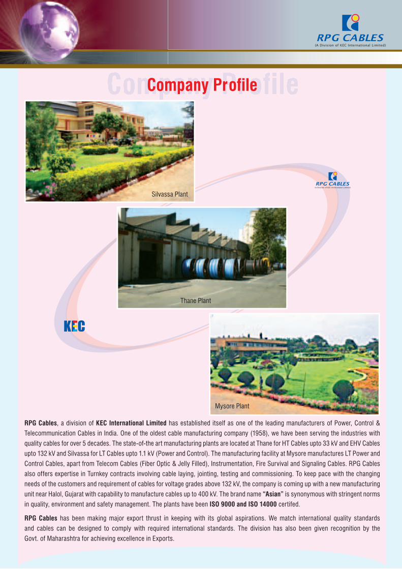
Company ProfileCompany Profile
Silvassa Plant
Mysore Plant
Thane Plant
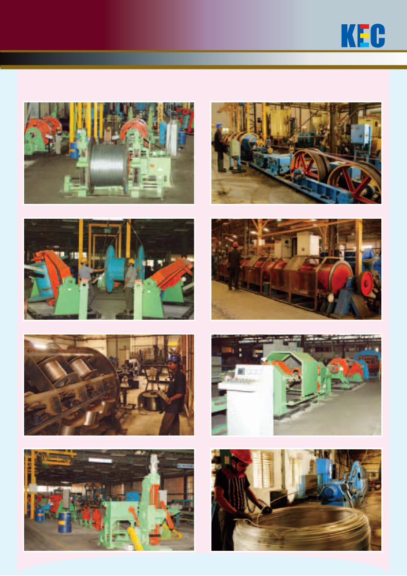
RPG Cables, a division of KEC International Limited has established itself as one of the leading manufacturers of Power, Control &
Telecommunication Cables in India. One of the oldest cable manufacturing company (1958), we have been serving the industries with
quality cables for over 5 decades. The state-of-the art manufacturing plants are located at Thane for HT Cables upto 33 kV and EHV Cables
upto 132 kV and Silvassa for LT Cables upto 1.1 kV (Power and Control). The manufacturing facility at Mysore manufactures LT Power and
Control Cables, apart from Telecom Cables (Fiber Optic & Jelly Filled), Instrumentation, Fire Survival and Signaling Cables. RPG Cables
also offers expertise in Turnkey contracts involving cable laying, jointing, testing and commissioning. To keep pace with the changing
needs of the customers and requirement of cables for voltage grades above 132 kV, the company is coming up with a new manufacturing
unit near Halol, Gujarat with capability to manufacture cables up to 400 kV. The brand name “Asian” is synonymous with stringent norms
in quality, environment and safety management. The plants have been ISO 9000 and ISO 14000 certifed.
RPG Cables has been making major export thrust in keeping with its global aspirations. We match international quality standards
and cables can be designed to comply with required international standards. The division has also been given recognition by the
Govt. of Maharashtra for achieving excellence in Exports.
1
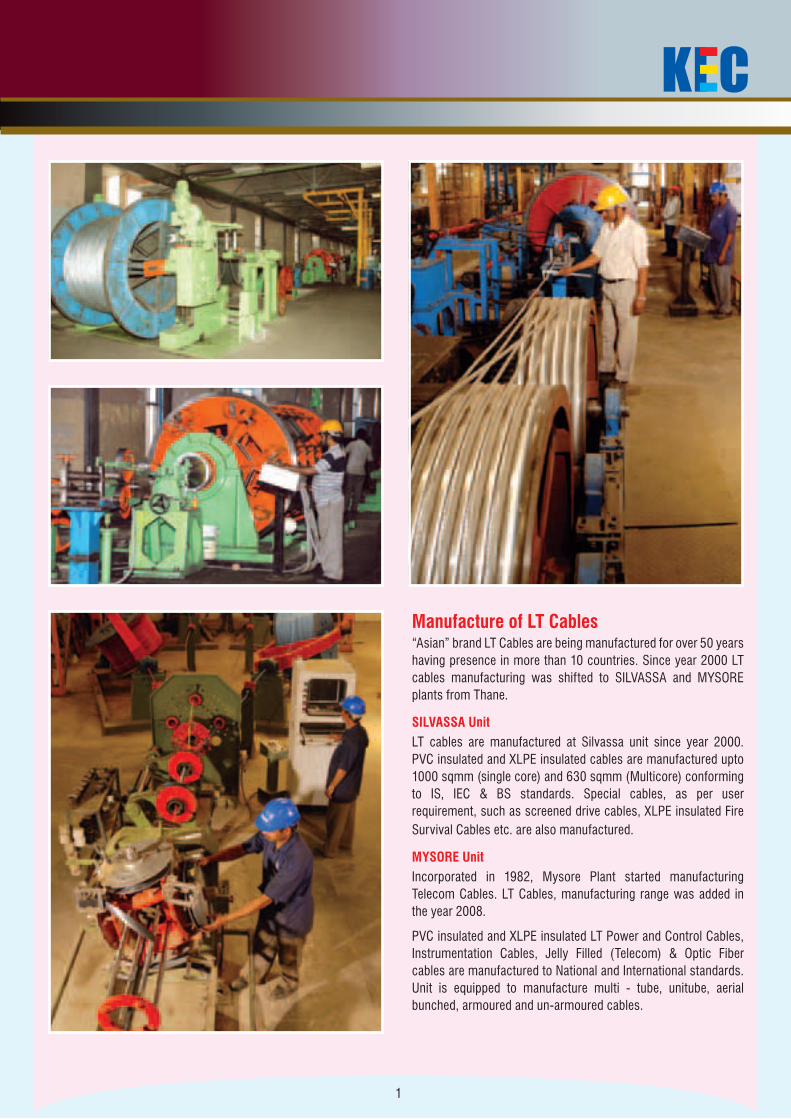
Manufacture of LT Cables“Asian” brand LT Cables are being manufactured for over 50 years having presence in more than 10 countries. Since year 2000 LT cables manufacturing was shifted to SILVASSA and MYSORE plants from Thane.
SILVASSA UnitLT cables are manufactured at Silvassa unit since year 2000. PVC insulated and XLPE insulated cables are manufactured upto 1000 sqmm (single core) and 630 sqmm (Multicore) conforming to IS, IEC & BS standards. Special cables, as per user requirement, such as screened drive cables, XLPE insulated Fire Survival Cables etc. are also manufactured.
MYSORE UnitIncorporated in 1982, Mysore Plant started manufacturing Telecom Cables. LT Cables, manufacturing range was added in the year 2008.
PVC insulated and XLPE insulated LT Power and Control Cables, Instrumentation Cables, Jelly Filled (Telecom) & Optic Fiber cables are manufactured to National and International standards. Unit is equipped to manufacture multi - tube, unitube, aerial bunched, armoured and un-armoured cables.
2
SPECIFICATION & CONSTRUCTION1.1Kv cables are designed and manufactured based on the national (IS) & international (IEC, BS) standards and project based customer
specifications. Following are the standard stages of cable design & manufacturing.
CONDUCTOR - The current carrying component :
KEC offer cables with Electrolytic Copper (Plain or Tinned) and Aluminium conductor in form of Solid, Stranded Circular, Compacted
Circular and Shaped as per IS 8130, IEC 60228 & BS EN 60228. The sector shaped conductor are manufactured with pre-spiral lay which
gives compact shape to the cable with reduced diameter at laid up stage.
INSULATION - The dielectric barrier to meet rated voltage level :
XLPE, the 90°C thermoset dielectric, is applied as insulation over the conductor by extrusion process.
Cross Linked Polyethyelene (XLPE) as per IS 7098-1, IEC 60502-1, BS 7655.
Laying up of Cores -
The multi-cores are Laid-up with appropriate tooling to form a compact circular shape, PVC fillers can be applied (wherever necessary) to
provide circular shape.
INNERSHEATH - The bedding for armour :
PVC / LSZH innersheath is applied as a protection over the laid up cores, Innersheath can be offered in two forms Extruded or Taped.
Extruded PVC bedding of ST2/LSZH PVC as per IS 5831, IEC 60502-1, BS 7655.
Taped Bedding of Thermoplastic tape to be compatible with temperature rating of the cable as per IS 7098-1, IEC 60502-1.
ARMOUR - The mechanical protection (or Earthing element) of cable :
Galvanised Steel Round Wire as per IS 3975, IEC 60502-1, BS 10257.
Galvanised Steel Flat Strip as per IS 3975, IEC 60502-1.
For Single Core cables to be used in AC circuits Aluminium Round Wire or Flat Strip armour is provided to avoid magnetic hysteresis losses.
For cables to be used in mines, required armour conductance (may be 75% to 40%) can be achieved by Double wire armour or by
incorporating Tinned Copper Wires with Galvanised Steel Wires
OUTERSHEATH -
PVC / LSZH outersheath is applied by extrusion process generally Black in colour with sequential length marking and required details
Printed with non-contact ink jet printer.
Poly-Vinyl Chloride (PVC) as per IS 5831, IEC 60502-1, BS 7655.
Low Smoke Zero Halogen (LSZH) as per IEC 60502-1.
3
SPECIAL REQUIREMENTSKEC Cables can be custom designed & manufactured for special requirements as follows :
FR innersheath & outersheath material can be offered to meet the requirement of reduced Flame propagation characteristics
as per ASTM-2863, IEC 60332 Part 3.
FRLS innersheath & outersheath material can be offered to meet the requirement of reduced Flame propagation
characteristics and Low Smoke & Low acid gas emission as per ASTM 2843, ASTM-2863, IEC 60332 Part 3, IEC 60754-1,
SS 424-14-75.
Copper tape, Copper wires or Aluminium tape can be provided as shielding / screening over laid up cores or innersheath.
Cables with LEAD sheath over bedding can be offered.
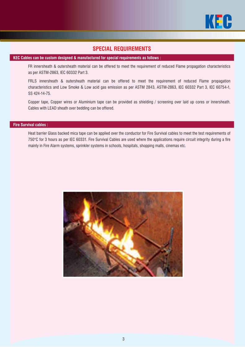
Fire Survival cables :
Heat barrier Glass backed mica tape can be applied over the conductor for Fire Survival cables to meet the test requirements of
750°C for 3 hours as per IEC 60331. Fire Survival Cables are used where the applications require circuit integrity during a fire
mainly in Fire Alarm systems, sprinkler systems in schools, hospitals, shopping malls, cinemas etc.
4
TYPICAL CROSS SECTIONAL VIEW OF LT CABLES
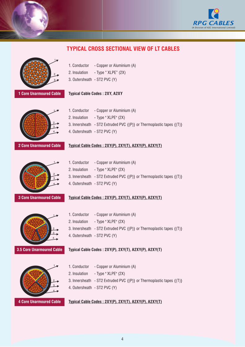
1. Conductor - Copper or Aluminium (A)
2. Insulation - Type “ XLPE” (2X)
3. Outersheath - ST2 PVC (Y)
1 Core Unarmoured Cable Typical Cable Codes : 2XY, A2XY
1. Conductor - Copper or Aluminium (A)
2. Insulation - Type " XLPE" (2X)
3. Innersheath - ST2 Extruded PVC {(P)} or Thermoplastic tapes {(T)}
4. Outersheath - ST2 PVC (Y)
2 Core Unarmoured Cable Typical Cable Codes : 2XY(P), 2XY(T), A2XY(P), A2XY(T)
1. Conductor - Copper or Aluminium (A)
2. Insulation - Type " XLPE" (2X)
3. Innersheath - ST2 Extruded PVC {(P)} or Thermoplastic tapes {(T)}
4. Outersheath - ST2 PVC (Y)
3 Core Unarmoured Cable Typical Cable Codes : 2XY(P), 2XY(T), A2XY(P), A2XY(T)
1. Conductor - Copper or Aluminium (A)
2. Insulation - Type " XLPE" (2X)
3. Innersheath - ST2 Extruded PVC {(P)} or Thermoplastic tapes {(T)}
4. Outersheath - ST2 PVC (Y)
3.5 Core Unarmoured Cable Typical Cable Codes : 2XY(P), 2XY(T), A2XY(P), A2XY(T)
1. Conductor - Copper or Aluminium (A)
2. Insulation - Type " XLPE" (2X)
3. Innersheath - ST2 Extruded PVC {(P)} or Thermoplastic tapes {(T)}
4. Outersheath - ST2 PVC (Y)
4 Core Unarmoured Cable Typical Cable Codes : 2XY(P), 2XY(T), A2XY(P), A2XY(T)
5
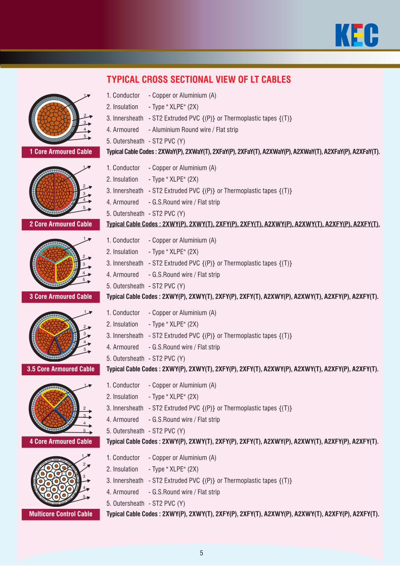
TYPICAL CROSS SECTIONAL VIEW OF LT CABLES
1. Conductor - Copper or Aluminium (A)
2. Insulation - Type " XLPE" (2X)
3. Innersheath - ST2 Extruded PVC {(P)} or Thermoplastic tapes {(T)}
4. Armoured - Aluminium Round wire / Flat strip
5. Outersheath - ST2 PVC (Y)
1 Core Armoured Cable Typical Cable Codes : 2XWaY(P), 2XWaY(T), 2XFaY(P), 2XFaY(T), A2XWaY(P), A2XWaY(T), A2XFaY(P), A2XFaY(T).
1. Conductor - Copper or Aluminium (A)
2. Insulation - Type " XLPE" (2X)
3. Innersheath - ST2 Extruded PVC {(P)} or Thermoplastic tapes {(T)}
4. Armoured - G.S.Round wire / Flat strip
5. Outersheath - ST2 PVC (Y)
2 Core Armoured Cable Typical Cable Codes : 2XWY(P), 2XWY(T), 2XFY(P), 2XFY(T), A2XWY(P), A2XWY(T), A2XFY(P), A2XFY(T).
1. Conductor - Copper or Aluminium (A)
2. Insulation - Type " XLPE" (2X)
3. Innersheath - ST2 Extruded PVC {(P)} or Thermoplastic tapes {(T)}
4. Armoured - G.S.Round wire / Flat strip
5. Outersheath - ST2 PVC (Y)
3 Core Armoured Cable Typical Cable Codes : 2XWY(P), 2XWY(T), 2XFY(P), 2XFY(T), A2XWY(P), A2XWY(T), A2XFY(P), A2XFY(T).
1. Conductor - Copper or Aluminium (A)
2. Insulation - Type " XLPE" (2X)
3. Innersheath - ST2 Extruded PVC {(P)} or Thermoplastic tapes {(T)}
4. Armoured - G.S.Round wire / Flat strip
5. Outersheath - ST2 PVC (Y)
3.5 Core Armoured Cable Typical Cable Codes : 2XWY(P), 2XWY(T), 2XFY(P), 2XFY(T), A2XWY(P), A2XWY(T), A2XFY(P), A2XFY(T).
1. Conductor - Copper or Aluminium (A)
2. Insulation - Type " XLPE" (2X)
3. Innersheath - ST2 Extruded PVC {(P)} or Thermoplastic tapes {(T)}
4. Armoured - G.S.Round wire / Flat strip
5. Outersheath - ST2 PVC (Y)
4 Core Armoured Cable Typical Cable Codes : 2XWY(P), 2XWY(T), 2XFY(P), 2XFY(T), A2XWY(P), A2XWY(T), A2XFY(P), A2XFY(T).
1. Conductor - Copper or Aluminium (A)
2. Insulation - Type " XLPE" (2X)
3. Innersheath - ST2 Extruded PVC {(P)} or Thermoplastic tapes {(T)}
4. Armoured - G.S.Round wire / Flat strip
5. Outersheath - ST2 PVC (Y)
Multicore Control Cable Typical Cable Codes : 2XWY(P), 2XWY(T), 2XFY(P), 2XFY(T), A2XWY(P), A2XWY(T), A2XFY(P), A2XFY(T).
6
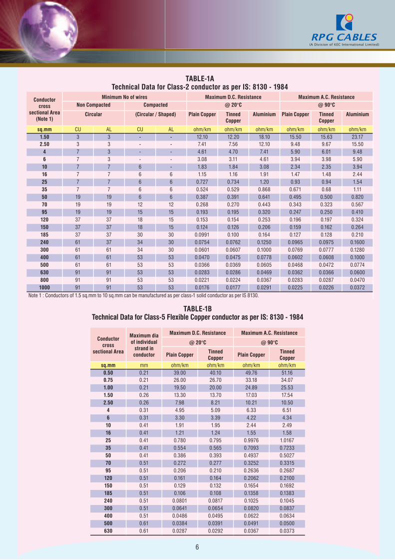
TABLE-1ATechnical Data for Class-2 conductor as per IS: 8130 - 1984
Conductor cross
sectional Area (Note 1)
Minimum No of wires Maximum D.C. Resistance Maximum A.C. ResistanceNon Compacted Compacted @ 20°C @ 90°C
Circular (Circular / Shaped) Plain Copper Tinned Copper
Aluminium Plain Copper Tinned Copper
Aluminium
sq.mm CU AL CU AL ohm/km ohm/km ohm/km ohm/km ohm/km ohm/km1.50 3 3 - - 12.10 12.20 18.10 15.50 15.63 23.172.50 3 3 - - 7.41 7.56 12.10 9.48 9.67 15.50
4 7 3 - - 4.61 4.70 7.41 5.90 6.01 9.486 7 3 - - 3.08 3.11 4.61 3.94 3.98 5.9010 7 7 6 - 1.83 1.84 3.08 2.34 2.35 3.9416 7 7 6 6 1.15 1.16 1.91 1.47 1.48 2.4425 7 7 6 6 0.727 0.734 1.20 0.93 0.94 1.5435 7 7 6 6 0.524 0.529 0.868 0.671 0.68 1.1150 19 19 6 6 0.387 0.391 0.641 0.495 0.500 0.82070 19 19 12 12 0.268 0.270 0.443 0.343 0.323 0.56795 19 19 15 15 0.193 0.195 0.320 0.247 0.250 0.410120 37 37 18 15 0.153 0.154 0.253 0.196 0.197 0.324150 37 37 18 15 0.124 0.126 0.206 0.159 0.162 0.264185 37 37 30 30 0.0991 0.100 0.164 0.127 0.128 0.210240 61 37 34 30 0.0754 0.0762 0.1250 0.0965 0.0975 0.1600300 61 61 34 30 0.0601 0.0607 0.1000 0.0769 0.0777 0.1280400 61 61 53 53 0.0470 0.0475 0.0778 0.0602 0.0608 0.1000500 61 61 53 53 0.0366 0.0369 0.0605 0.0468 0.0472 0.0774630 91 91 53 53 0.0283 0.0286 0.0469 0.0362 0.0366 0.0600800 91 91 53 53 0.0221 0.0224 0.0367 0.0283 0.0287 0.04701000 91 91 53 53 0.0176 0.0177 0.0291 0.0225 0.0226 0.0372
Note 1 : Conductors of 1.5 sq.mm to 10 sq.mm can be manufactured as per class-1 solid conductor as per IS 8130.
TABLE-1BTechnical Data for Class-5 Flexible Copper conductor as per IS: 8130 - 1984
Conductor cross
sectional Area
Maximum dia of individual
strand in conductor
Maximum D.C. Resistance Maximum A.C. Resistance
@ 20°C @ 90°C
Plain CopperTinned Copper
Plain CopperTinned Copper
sq.mm mm ohm/km ohm/km ohm/km ohm/km0.50 0.21 39.00 40.10 49.76 51.160.75 0.21 26.00 26.70 33.18 34.071.00 0.21 19.50 20.00 24.89 25.531.50 0.26 13.30 13.70 17.03 17.542.50 0.26 7.98 8.21 10.21 10.50
4 0.31 4.95 5.09 6.33 6.516 0.31 3.30 3.39 4.22 4.3410 0.41 1.91 1.95 2.44 2.4916 0.41 1.21 1.24 1.55 1.5825 0.41 0.780 0.795 0.9976 1.016735 0.41 0.554 0.565 0.7093 0.723350 0.41 0.386 0.393 0.4937 0.502770 0.51 0.272 0.277 0.3252 0.331595 0.51 0.206 0.210 0.2636 0.2687120 0.51 0.161 0.164 0.2062 0.2100150 0.51 0.129 0.132 0.1654 0.1692185 0.51 0.106 0.108 0.1358 0.1383240 0.51 0.0801 0.0817 0.1025 0.1045300 0.51 0.0641 0.0654 0.0820 0.0837400 0.51 0.0486 0.0495 0.0622 0.0634500 0.61 0.0384 0.0391 0.0491 0.0500630 0.61 0.0287 0.0292 0.0367 0.0373
7
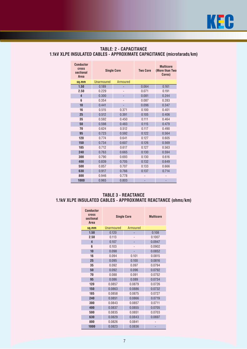
TABLE: 2 - CAPACITANCE1.1kV XLPE INSULATED CABLES - APPROXIMATE CAPACITANCE (microfarads/km)
Conductor cross
sectional Area
Single Core Two CoreMulticore
(More than Two Cores)
sq.mm Unarmoured Armoured1.50 0.189 - 0.064 0.1612.50 0.229 - 0.071 0.191
4 0.300 - 0.081 0.2446 0.354 - 0.087 0.28310 0.441 - 0.096 0.34716 0.515 0.371 0.100 0.40125 0.512 0.391 0.105 0.40635 0.592 0.450 0.111 0.46450 0.598 0.483 0.115 0.47970 0.624 0.512 0.117 0.49095 0.723 0.592 0.122 0.564120 0.774 0.641 0.127 0.605150 0.734 0.607 0.126 0.569185 0.712 0.617 0.127 0.563240 0.763 0.665 0.130 0.594300 0.790 0.693 0.130 0.616400 0.839 0.705 0.132 0.649500 0.857 0.707 0.133 0.666630 0.917 0.766 0.137 0.714800 0.946 0.778 - -1000 0.965 0.803 - -
TABLE 3 - REACTANCE1.1kV XLPE INSULATED CABLES - APPROXIMATE REACTANCE (ohms/km)
Conductor cross
sectional Area
Single Core Multicore
sq.mm Unarmoured Armoured1.50 0.120 - 0.1082.50 0.113 - 0.1007
4 0.107 - 0.09476 0.103 - 0.090210 0.098 - 0.085216 0.094 0.101 0.081525 0.095 0.100 0.081635 0.092 0.097 0.079450 0.092 0.096 0.079270 0.088 0.091 0.075295 0.086 0.089 0.0734120 0.0857 0.0879 0.0726150 0.0863 0.0886 0.0732185 0.0858 0.0875 0.0727240 0.0851 0.0866 0.0719300 0.0843 0.0857 0.0711400 0.0837 0.0855 0.0705500 0.0835 0.0851 0.0703630 0.0829 0.0843 0.0697800 0.0826 0.0841 -1000 0.0823 0.0836 -
8
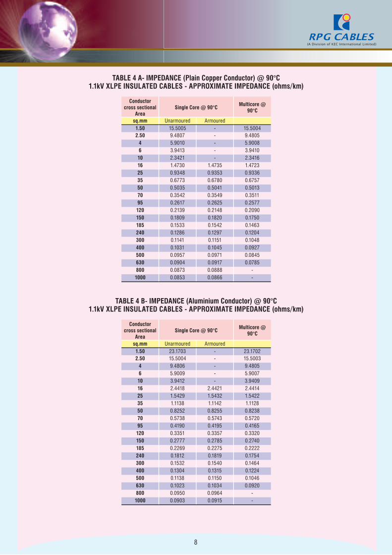
TABLE 4 A- IMPEDANCE (Plain Copper Conductor) @ 90°C1.1kV XLPE INSULATED CABLES - APPROXIMATE IMPEDANCE (ohms/km)
Conductor cross sectional
AreaSingle Core @ 90°C
Multicore @ 90°C
sq.mm Unarmoured Armoured1.50 15.5005 - 15.50042.50 9.4807 - 9.4805
4 5.9010 - 5.90086 3.9413 - 3.941010 2.3421 - 2.341616 1.4730 1.4735 1.472325 0.9348 0.9353 0.933635 0.6773 0.6780 0.675750 0.5035 0.5041 0.501370 0.3542 0.3549 0.351195 0.2617 0.2625 0.2577120 0.2139 0.2148 0.2090150 0.1809 0.1820 0.1750185 0.1533 0.1542 0.1463240 0.1286 0.1297 0.1204300 0.1141 0.1151 0.1048400 0.1031 0.1045 0.0927500 0.0957 0.0971 0.0845630 0.0904 0.0917 0.0785800 0.0873 0.0888 -1000 0.0853 0.0866 -
TABLE 4 B- IMPEDANCE (Aluminium Conductor) @ 90°C1.1kV XLPE INSULATED CABLES - APPROXIMATE IMPEDANCE (ohms/km)
Conductor cross sectional
AreaSingle Core @ 90°C
Multicore @ 90°C
sq.mm Unarmoured Armoured1.50 23.1703 - 23.17022.50 15.5004 - 15.5003
4 9.4806 - 9.48056 5.9009 - 5.900710 3.9412 - 3.940916 2.4418 2.4421 2.441425 1.5429 1.5432 1.542235 1.1138 1.1142 1.112850 0.8252 0.8255 0.823870 0.5738 0.5743 0.572095 0.4190 0.4195 0.4165120 0.3351 0.3357 0.3320150 0.2777 0.2785 0.2740185 0.2269 0.2275 0.2222240 0.1812 0.1819 0.1754300 0.1532 0.1540 0.1464400 0.1304 0.1315 0.1224500 0.1138 0.1150 0.1046630 0.1023 0.1034 0.0920800 0.0950 0.0964 -1000 0.0903 0.0915 -
9
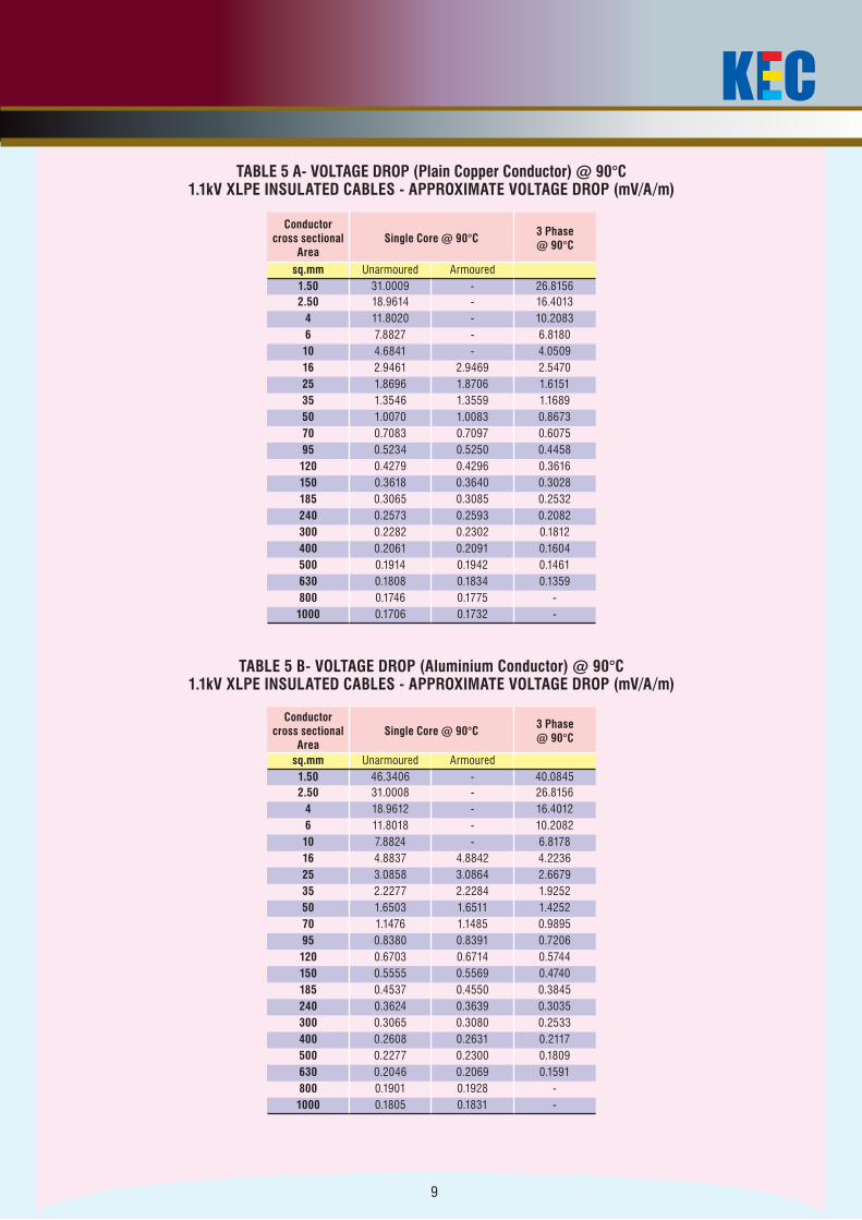
TABLE 5 A- VOLTAGE DROP (Plain Copper Conductor) @ 90°C1.1kV XLPE INSULATED CABLES - APPROXIMATE VOLTAGE DROP (mV/A/m)
Conductor cross sectional
AreaSingle Core @ 90°C
3 Phase @ 90°C
sq.mm Unarmoured Armoured1.50 31.0009 - 26.81562.50 18.9614 - 16.4013
4 11.8020 - 10.20836 7.8827 - 6.818010 4.6841 - 4.050916 2.9461 2.9469 2.547025 1.8696 1.8706 1.615135 1.3546 1.3559 1.168950 1.0070 1.0083 0.867370 0.7083 0.7097 0.607595 0.5234 0.5250 0.4458120 0.4279 0.4296 0.3616150 0.3618 0.3640 0.3028185 0.3065 0.3085 0.2532240 0.2573 0.2593 0.2082300 0.2282 0.2302 0.1812400 0.2061 0.2091 0.1604500 0.1914 0.1942 0.1461630 0.1808 0.1834 0.1359800 0.1746 0.1775 -1000 0.1706 0.1732 -
TABLE 5 B- VOLTAGE DROP (Aluminium Conductor) @ 90°C1.1kV XLPE INSULATED CABLES - APPROXIMATE VOLTAGE DROP (mV/A/m)
Conductor cross sectional
AreaSingle Core @ 90°C
3 Phase @ 90°C
sq.mm Unarmoured Armoured1.50 46.3406 - 40.08452.50 31.0008 - 26.8156
4 18.9612 - 16.40126 11.8018 - 10.208210 7.8824 - 6.817816 4.8837 4.8842 4.223625 3.0858 3.0864 2.667935 2.2277 2.2284 1.925250 1.6503 1.6511 1.425270 1.1476 1.1485 0.989595 0.8380 0.8391 0.7206120 0.6703 0.6714 0.5744150 0.5555 0.5569 0.4740185 0.4537 0.4550 0.3845240 0.3624 0.3639 0.3035300 0.3065 0.3080 0.2533400 0.2608 0.2631 0.2117500 0.2277 0.2300 0.1809630 0.2046 0.2069 0.1591800 0.1901 0.1928 -1000 0.1805 0.1831 -
10
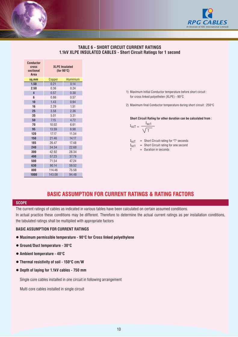
TABLE 6 - SHORT CIRCUIT CURRENT RATINGS1.1kV XLPE INSULATED CABLES - Short Circuit Ratings for 1 second
Conductor cross
sectional Area
XLPE Insulated (for 90°C)
sq.mm Copper Aluminium1.50 0.21 0.142.50 0.36 0.24
4 0.57 0.386 0.86 0.5710 1.43 0.9416 2.29 1.5125 3.58 2.3635 5.01 3.3150 7.15 4.7270 10.02 6.6195 13.59 8.98120 17.17 11.34150 21.46 14.17185 26.47 17.48240 34.34 22.68300 42.92 28.34400 57.23 37.79500 71.54 47.24630 90.14 59.52800 114.46 75.581000 143.08 94.48
1) Maximum Initial Conductor temperature before short circuit :
for cross linked polyethelen (XLPE) - 90°C
2) Maximum final Conductor temperature during short circuit : 250°C
Short Circuit Rating for other duration can be calculated from :
IscT = Short Circuit rating for "T" secondsIsc1 = Short Circuit rating for one secondT = Duration in seconds
BASIC ASSUMPTION FOR CURRENT RATINGS & RATING FACTORSSCOPE
The current ratings of cables as indicated in various tables have been calculated on certain assumed conditions.
In actual practice these conditions may be different. Therefore to determine the actual current ratings as per installation conditions,
the tabulated ratings shall be multiplied with appropriate factors
BASIC ASSUMPTION FOR CURRENT RATINGS
l Maximum permissible temperature - 90°C for Cross linked polyethylene
l Ground/Duct temperature - 30°C
l Ambient temperature - 40°C
l Thermal resistivity of soil - 150°C cm/W
l Depth of laying for 1.1kV cables - 750 mm
Single core cables installed in one circuit in following arrangement
Multi core cables installed in single circuit
11
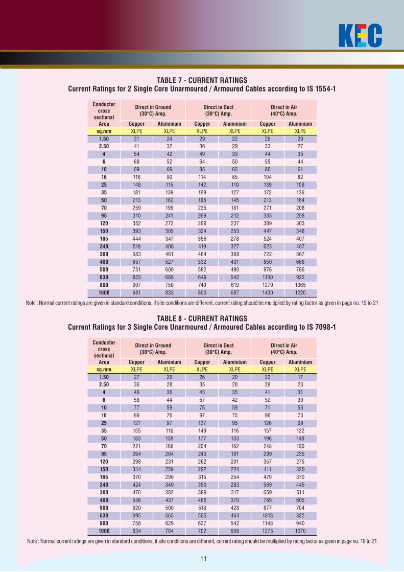
TABLE 7 - CURRENT RATINGSCurrent Ratings for 2 Single Core Unarmoured / Armoured Cables according to IS 1554-1
Conductor cross
sectional Area
Direct in Ground (30°C) Amp.
Direct in Duct (30°C) Amp.
Direct in Air (40°C) Amp.
Copper Aluminium Copper Aluminium Copper Aluminiumsq.mm XLPE XLPE XLPE XLPE XLPE XLPE1.50 31 24 29 22 25 202.50 41 32 36 29 33 27
4 54 42 49 39 44 356 68 52 64 50 55 4410 89 69 85 65 80 6116 116 90 114 85 104 8225 148 115 142 110 139 10935 181 139 169 127 172 13650 213 162 195 145 213 16470 259 199 235 181 271 20895 310 241 269 212 335 258120 352 272 299 237 389 303150 393 305 324 253 447 348185 444 347 356 278 524 407240 518 406 419 327 623 487300 583 461 464 368 722 567400 657 527 532 431 850 668500 731 600 582 490 976 786630 823 666 649 542 1130 922800 907 750 740 619 1279 10651000 981 833 800 687 1430 1220
Note : Normal current ratings are given in standard conditions, if site conditions are different, current rating should be multiplied by rating factor as given in page no. 19 to 21
TABLE 8 - CURRENT RATINGSCurrent Ratings for 3 Single Core Unarmoured / Armoured Cables according to IS 7098-1
Conductor cross
sectional Area
Direct in Ground (30°C) Amp.
Direct in Duct (30°C) Amp.
Direct in Air (40°C) Amp.
Copper Aluminium Copper Aluminium Copper Aluminiumsq.mm XLPE XLPE XLPE XLPE XLPE XLPE1.50 27 20 26 20 22 172.50 36 28 35 28 29 23
4 46 36 45 35 41 316 58 44 57 42 52 3910 77 59 76 59 71 5316 99 76 97 75 96 7325 127 97 127 95 126 9935 155 116 149 116 157 12250 183 139 177 133 196 14970 221 168 204 162 248 19095 264 204 240 181 299 235120 298 231 262 201 357 275150 334 259 292 224 411 320185 370 290 315 254 479 370240 424 340 350 283 569 445300 470 382 389 317 659 514400 556 437 466 370 769 605500 620 500 518 428 877 704630 695 565 555 464 1013 822800 758 629 637 542 1148 9401000 834 704 702 606 1275 1070
Note : Normal current ratings are given in standard conditions, if site conditions are different, current rating should be multiplied by rating factor as given in page no. 19 to 21
12
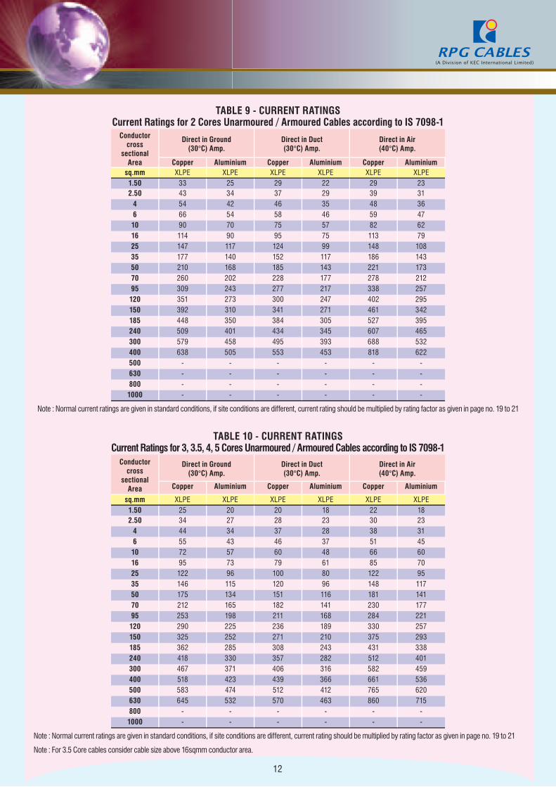
TABLE 9 - CURRENT RATINGSCurrent Ratings for 2 Cores Unarmoured / Armoured Cables according to IS 7098-1
Conductor cross
sectional Area
Direct in Ground (30°C) Amp.
Direct in Duct (30°C) Amp.
Direct in Air (40°C) Amp.
Copper Aluminium Copper Aluminium Copper Aluminiumsq.mm XLPE XLPE XLPE XLPE XLPE XLPE1.50 33 25 29 22 29 232.50 43 34 37 29 39 31
4 54 42 46 35 48 366 66 54 58 46 59 4710 90 70 75 57 82 6216 114 90 95 75 113 7925 147 117 124 99 148 10835 177 140 152 117 186 14350 210 168 185 143 221 17370 260 202 228 177 278 21295 309 243 277 217 338 257120 351 273 300 247 402 295150 392 310 341 271 461 342185 448 350 384 305 527 395240 509 401 434 345 607 465300 579 458 495 393 688 532400 638 505 553 453 818 622500 - - - - - -630 - - - - - -800 - - - - - -1000 - - - - - -
Note : Normal current ratings are given in standard conditions, if site conditions are different, current rating should be multiplied by rating factor as given in page no. 19 to 21
TABLE 10 - CURRENT RATINGSCurrent Ratings for 3, 3.5, 4, 5 Cores Unarmoured / Armoured Cables according to IS 7098-1
Conductor cross
sectional Area
Direct in Ground (30°C) Amp.
Direct in Duct (30°C) Amp.
Direct in Air (40°C) Amp.
Copper Aluminium Copper Aluminium Copper Aluminium
sq.mm XLPE XLPE XLPE XLPE XLPE XLPE1.50 25 20 20 18 22 182.50 34 27 28 23 30 23
4 44 34 37 28 38 316 55 43 46 37 51 4510 72 57 60 48 66 6016 95 73 79 61 85 7025 122 96 100 80 122 9535 146 115 120 96 148 11750 175 134 151 116 181 14170 212 165 182 141 230 17795 253 198 211 168 284 221120 290 225 236 189 330 257150 325 252 271 210 375 293185 362 285 308 243 431 338240 418 330 357 282 512 401300 467 371 406 316 582 459400 518 423 439 366 661 536500 583 474 512 412 765 620630 645 532 570 463 860 715800 - - - - - -1000 - - - - - -
Note : Normal current ratings are given in standard conditions, if site conditions are different, current rating should be multiplied by rating factor as given in page no. 19 to 21
Note : For 3.5 Core cables consider cable size above 16sqmm conductor area.
13
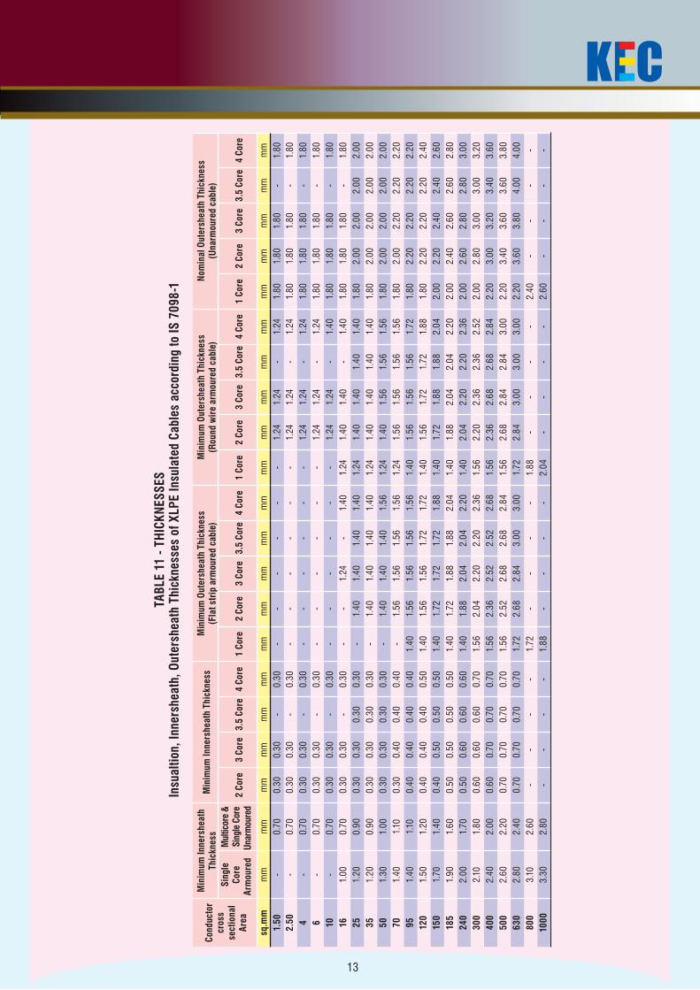
TABL
E 11
- TH
ICKN
ESSE
SIn
sual
tion,
Inne
rshe
ath,
Out
ersh
eath
Thi
ckne
sses
of X
LPE
Insu
late
d Ca
bles
acc
ordi
ng to
IS 7
098-
1
Cond
ucto
r cr
oss
sect
iona
l Ar
ea
Min
imum
Inne
rshe
ath
Thic
knes
sM
inim
um In
ners
heat
h Th
ickn
ess
Min
imum
Out
ersh
eath
Thi
ckne
ss
(Fla
t str
ip a
rmou
red
cabl
e)M
inim
um O
uter
shea
th T
hick
ness
(R
ound
wir
e ar
mou
red
cabl
e)N
omin
al O
uter
shea
th T
hick
ness
(U
narm
oure
d ca
ble)
Sing
le
Core
Ar
mou
red
Mul
ticor
e &
Si
ngle
Cor
e Un
arm
oure
d 2
Core
3 Co
re3.
5 Co
re4
Core
1 Co
re2
Core
3 Co
re3.
5 Co
re4
Core
1 Co
re2
Core
3 Co
re3.
5 Co
re4
Core
1 Co
re2
Core
3 Co
re3.
5 Co
re4
Core
sq.m
m
mm
mm
mm
mm
mm
mm
mm
mm
mm
mm
mm
mm
mm
mm
mm
mm
mm
mm
mm
mm
mm
1.50
-0.
700.
300.
30-
0.30
--
--
--
1.24
1.24
-1.
241.
801.
801.
80-
1.80
2.50
-0.
700.
300.
30-
0.30
--
--
--
1.24
1.24
-1.
241.
801.
801.
80-
1.80
4-
0.70
0.30
0.30
-0.
30-
--
--
-1.
241.
24-
1.24
1.80
1.80
1.80
-1.
806
-0.
700.
300.
30-
0.30
--
--
--
1.24
1.24
-1.
241.
801.
801.
80-
1.80
10-
0.70
0.30
0.30
-0.
30-
--
--
-1.
241.
24-
1.40
1.80
1.80
1.80
-1.
8016
1.00
0.70
0.30
0.30
-0.
30-
-1.
24-
1.40
1.24
1.40
1.40
-1.
401.
801.
801.
80-
1.80
251.
200.
900.
300.
300.
300.
30-
1.40
1.40
1.40
1.40
1.24
1.40
1.40
1.40
1.40
1.80
2.00
2.00
2.00
2.00
351.
200.
900.
300.
300.
300.
30-
1.40
1.40
1.40
1.40
1.24
1.40
1.40
1.40
1.40
1.80
2.00
2.00
2.00
2.00
501.
301.
000.
300.
300.
300.
30-
1.40
1.40
1.40
1.56
1.24
1.40
1.56
1.56
1.56
1.80
2.00
2.00
2.00
2.00
701.
401.
100.
300.
400.
400.
40-
1.56
1.56
1.56
1.56
1.24
1.56
1.56
1.56
1.56
1.80
2.00
2.20
2.20
2.20
951.
401.
100.
400.
400.
400.
401.
401.
561.
561.
561.
561.
401.
561.
561.
561.
721.
802.
202.
202.
202.
2012
01.
501.
200.
400.
400.
400.
501.
401.
561.
561.
721.
721.
401.
561.
721.
721.
881.
802.
202.
202.
202.
4015
01.
701.
400.
400.
500.
500.
501.
401.
721.
721.
721.
881.
401.
721.
881.
882.
042.
002.
202.
402.
402.
6018
51.
901.
600.
500.
500.
500.
501.
401.
721.
881.
882.
041.
401.
882.
042.
042.
202.
002.
402.
602.
602.
8024
02.
001.
700.
500.
600.
600.
601.
401.
882.
042.
042.
201.
402.
042.
202.
202.
362.
002.
602.
802.
803.
0030
02.
101.
800.
600.
600.
600.
701.
562.
042.
202.
202.
361.
562.
202.
362.
362.
522.
002.
803.
003.
003.
2040
02.
402.
000.
600.
700.
700.
701.
562.
362.
522.
522.
681.
562.
362.
682.
682.
842.
203.
003.
203.
403.
6050
02.
602.
200.
700.
700.
700.
701.
562.
522.
682.
682.
841.
562.
682.
842.
843.
002.
203.
403.
603.
603.
8063
02.
802.
400.
700.
700.
700.
701.
722.
682.
843.
003.
001.
722.
843.
003.
003.
002.
203.
603.
804.
004.
0080
03.
102.
60-
--
-1.
72-
--
-1.
88-
--
-2.
40-
--
-10
003.
302.
80-
--
-1.
88-
--
-2.
04-
--
-2.
60-
--
-
14
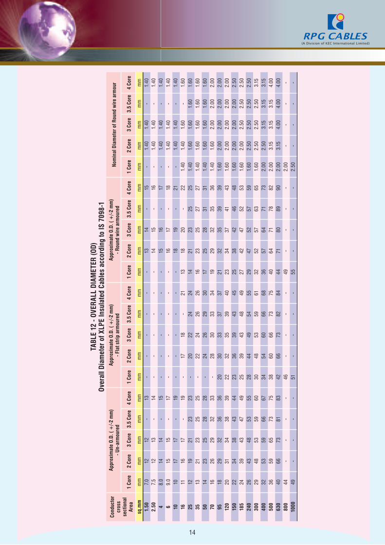
TABL
E 12
- OV
ERAL
L D
IAM
ETER
(OD)
Ove
rall
Diam
eter
of X
LPE
Insu
late
d Ca
bles
acc
ordi
ng to
IS 7
098-
1Co
nduc
tor
cros
s se
ctio
nal
Area
Appr
oxim
ate
O.D.
( +
/-2
mm
) - U
n-ar
mou
red
Appr
oxim
ate
O.D.
( +
/-2
mm
) - F
lat s
trip
arm
oure
dAp
prox
imat
e O.
D. (
+/-
2 m
m)
- Rou
nd w
ire
arm
oure
dN
omin
al D
iam
eter
of R
ound
wir
e ar
mou
r
1 Co
re2
Core
3 Co
re3.
5 Co
re4
Core
1 Co
re2
Core
3 Co
re3.
5 Co
re4
Core
1 Co
re2
Core
3 Co
re3.
5 Co
re4
Core
1 Co
re2
Core
3 Co
re3.
5 Co
re4
Core
sq.m
m
mm
mm
mm
mm
mm
mm
mm
mm
mm
mm
mm
mm
mm
mm
mm
mm
mm
mm
mm
mm
1.50
7.0
1212
-13
--
--
--
1314
-15
-1.
401.
40-
1.40
2.50
7.5
1213
-14
--
--
--
1415
-16
-1.
401.
40-
1.40
48.
014
14-
15-
--
--
-15
16-
17-
1.40
1.40
-1.
406
9.0
1515
-17
--
--
--
1617
-18
-1.
401.
40-
1.40
1010
1717
-19
--
--
--
1819
-21
-1.
401.
40-
1.40
1611
1617
-19
-17
18-
2113
1820
-22
1.40
1.40
1.60
-1.
6025
1219
2123
23-
2022
2424
1421
2325
251.
401.
601.
601.
601.
6035
1321
2325
25-
2224
2626
1623
2527
271.
401.
601.
601.
601.
6050
1423
2528
28-
2426
2930
1725
2831
311.
401.
601.
601.
601.
6070
1626
2932
33-
2830
3334
1929
3235
361.
401.
602.
002.
002.
0095
1829
3236
3620
3033
3737
2132
3539
391.
602.
002.
002.
002.
0012
020
3134
3839
2232
3539
4023
3437
4143
1.60
2.00
2.00
2.00
2.00
150
2234
3843
4423
3639
4345
2538
4246
481.
602.
002.
002.
002.
5018
524
3943
4749
2539
4348
4927
4247
5253
1.60
2.00
2.50
2.50
2.50
240
2643
4853
5528
4449
5455
2947
5257
591.
602.
502.
502.
502.
5030
029
4853
5960
3048
5359
6132
5257
6365
1.60
2.50
2.50
2.50
3.15
400
3253
5966
6734
5460
6668
3657
6471
732.
002.
503.
153.
153.
1550
036
5965
7375
3860
6673
7540
6471
7882
2.00
3.15
3.15
3.15
4.00
630
4066
7381
8342
6673
8284
4471
8089
902.
003.
154.
004.
004.
0080
044
--
--
46-
--
-49
--
--
2.00
--
--
1000
49-
--
-51
--
--
55-
--
-2.
50-
--
-
15
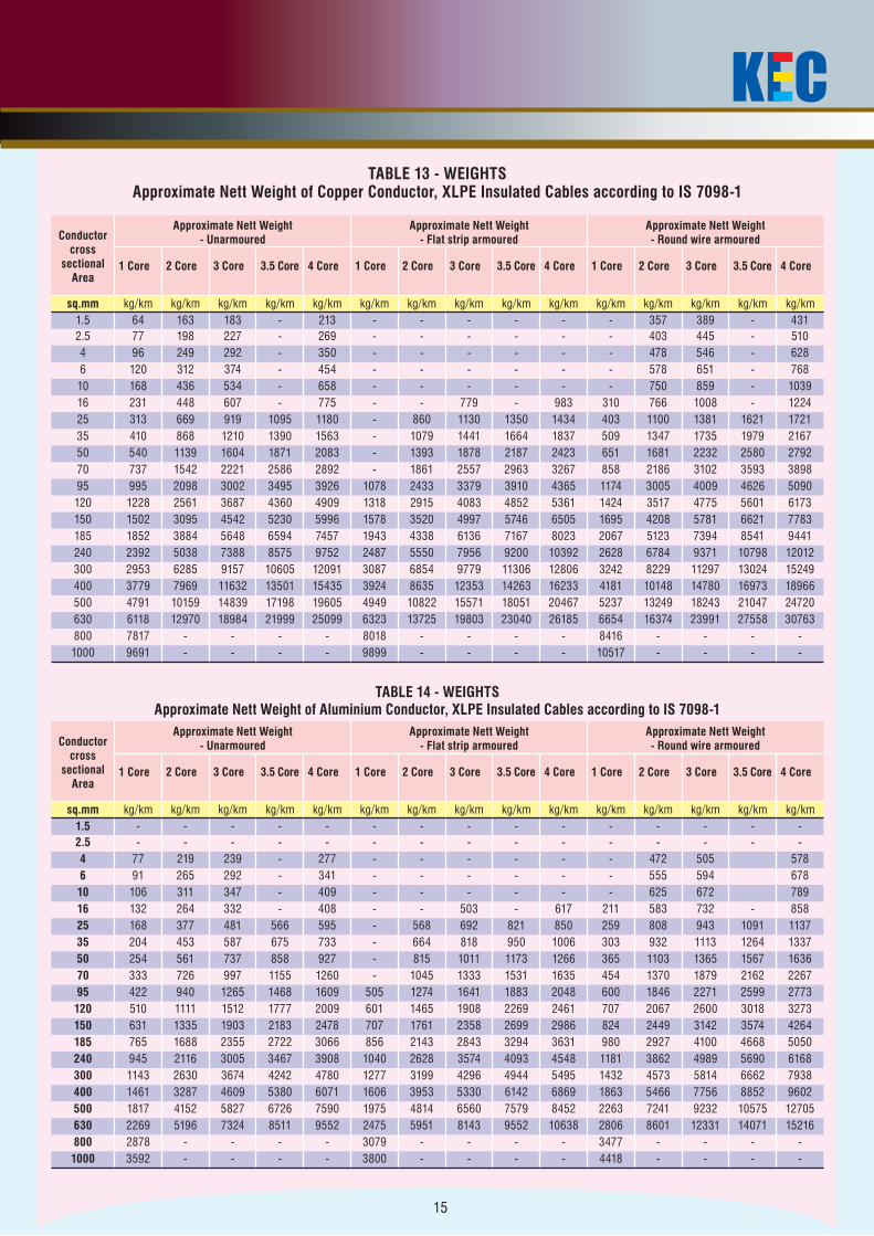
TABLE 13 - WEIGHTSApproximate Nett Weight of Copper Conductor, XLPE Insulated Cables according to IS 7098-1
Conductor cross
sectional Area
Approximate Nett Weight - Unarmoured
Approximate Nett Weight - Flat strip armoured
Approximate Nett Weight - Round wire armoured
1 Core 2 Core 3 Core 3.5 Core 4 Core 1 Core 2 Core 3 Core 3.5 Core 4 Core 1 Core 2 Core 3 Core 3.5 Core 4 Core
sq.mm kg/km kg/km kg/km kg/km kg/km kg/km kg/km kg/km kg/km kg/km kg/km kg/km kg/km kg/km kg/km1.5 64 163 183 - 213 - - - - - - 357 389 - 4312.5 77 198 227 - 269 - - - - - - 403 445 - 5104 96 249 292 - 350 - - - - - - 478 546 - 6286 120 312 374 - 454 - - - - - - 578 651 - 76810 168 436 534 - 658 - - - - - - 750 859 - 103916 231 448 607 - 775 - - 779 - 983 310 766 1008 - 122425 313 669 919 1095 1180 - 860 1130 1350 1434 403 1100 1381 1621 172135 410 868 1210 1390 1563 - 1079 1441 1664 1837 509 1347 1735 1979 216750 540 1139 1604 1871 2083 - 1393 1878 2187 2423 651 1681 2232 2580 279270 737 1542 2221 2586 2892 - 1861 2557 2963 3267 858 2186 3102 3593 389895 995 2098 3002 3495 3926 1078 2433 3379 3910 4365 1174 3005 4009 4626 5090120 1228 2561 3687 4360 4909 1318 2915 4083 4852 5361 1424 3517 4775 5601 6173150 1502 3095 4542 5230 5996 1578 3520 4997 5746 6505 1695 4208 5781 6621 7783185 1852 3884 5648 6594 7457 1943 4338 6136 7167 8023 2067 5123 7394 8541 9441240 2392 5038 7388 8575 9752 2487 5550 7956 9200 10392 2628 6784 9371 10798 12012300 2953 6285 9157 10605 12091 3087 6854 9779 11306 12806 3242 8229 11297 13024 15249400 3779 7969 11632 13501 15435 3924 8635 12353 14263 16233 4181 10148 14780 16973 18966500 4791 10159 14839 17198 19605 4949 10822 15571 18051 20467 5237 13249 18243 21047 24720630 6118 12970 18984 21999 25099 6323 13725 19803 23040 26185 6654 16374 23991 27558 30763800 7817 - - - - 8018 - - - - 8416 - - - -1000 9691 - - - - 9899 - - - - 10517 - - - -
TABLE 14 - WEIGHTSApproximate Nett Weight of Aluminium Conductor, XLPE Insulated Cables according to IS 7098-1
Conductor cross
sectional Area
Approximate Nett Weight - Unarmoured
Approximate Nett Weight - Flat strip armoured
Approximate Nett Weight - Round wire armoured
1 Core 2 Core 3 Core 3.5 Core 4 Core 1 Core 2 Core 3 Core 3.5 Core 4 Core 1 Core 2 Core 3 Core 3.5 Core 4 Core
sq.mm kg/km kg/km kg/km kg/km kg/km kg/km kg/km kg/km kg/km kg/km kg/km kg/km kg/km kg/km kg/km1.5 - - - - - - - - - - - - - - -2.5 - - - - - - - - - - - - - - -4 77 219 239 - 277 - - - - - - 472 505 5786 91 265 292 - 341 - - - - - - 555 594 67810 106 311 347 - 409 - - - - - - 625 672 78916 132 264 332 - 408 - - 503 - 617 211 583 732 - 85825 168 377 481 566 595 - 568 692 821 850 259 808 943 1091 113735 204 453 587 675 733 - 664 818 950 1006 303 932 1113 1264 133750 254 561 737 858 927 - 815 1011 1173 1266 365 1103 1365 1567 163670 333 726 997 1155 1260 - 1045 1333 1531 1635 454 1370 1879 2162 226795 422 940 1265 1468 1609 505 1274 1641 1883 2048 600 1846 2271 2599 2773120 510 1111 1512 1777 2009 601 1465 1908 2269 2461 707 2067 2600 3018 3273150 631 1335 1903 2183 2478 707 1761 2358 2699 2986 824 2449 3142 3574 4264185 765 1688 2355 2722 3066 856 2143 2843 3294 3631 980 2927 4100 4668 5050240 945 2116 3005 3467 3908 1040 2628 3574 4093 4548 1181 3862 4989 5690 6168300 1143 2630 3674 4242 4780 1277 3199 4296 4944 5495 1432 4573 5814 6662 7938400 1461 3287 4609 5380 6071 1606 3953 5330 6142 6869 1863 5466 7756 8852 9602500 1817 4152 5827 6726 7590 1975 4814 6560 7579 8452 2263 7241 9232 10575 12705630 2269 5196 7324 8511 9552 2475 5951 8143 9552 10638 2806 8601 12331 14071 15216800 2878 - - - - 3079 - - - - 3477 - - - -1000 3592 - - - - 3800 - - - - 4418 - - - -
16
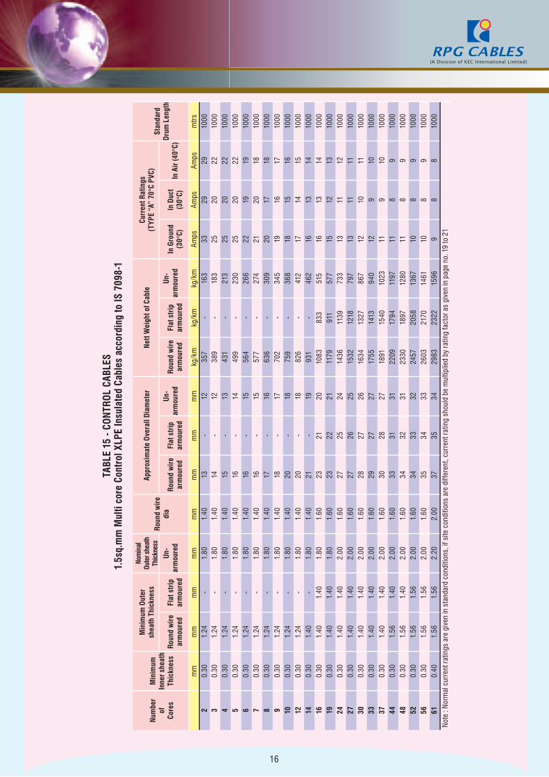
TABL
E 15
- CO
NTR
OL C
ABLE
S1.
5sq.
mm
Mul
ti co
re C
ontr
ol X
LPE
Insu
late
d Ca
bles
acc
ordi
ng to
IS 7
098-
1
Num
ber
of
Core
s
Min
imum
In
ner s
heat
h Th
ickn
ess
Min
imum
Out
er
shea
th T
hick
ness
Nom
inal
Ou
ter s
heat
h Th
ickn
ess
Roun
d w
ire
dia
Appr
oxim
ate
Ove
rall
Dia
met
erN
ett W
eigh
t of C
able
Curr
ent R
atin
gs(T
YPE
“A”
70°C
PVC
)St
anda
rd
Dru
m L
engt
hRo
und
wir
e ar
mou
red
Flat
str
ip
arm
oure
d
Un-
ar
mou
red
Roun
d w
ire
arm
oure
dFl
at s
trip
ar
mou
red
Un-
ar
mou
red
Roun
d w
ire
arm
oure
dFl
at s
trip
ar
mou
red
Un-
ar
mou
red
In G
roun
d (3
0°C)
In D
uct
(30°
C)In
Air
(40°
C)
mm
mm
mm
mm
mm
mm
mm
mm
kg/k
mkg
/km
kg/k
mAm
psAm
psAm
psm
trs2
0.30
1.24
-1.
801.
4013
-12
357
-16
333
2929
1000
30.
301.
24-
1.80
1.40
14-
1238
9-
183
2520
2210
004
0.30
1.24
-1.
801.
4015
-13
431
-21
325
2022
1000
50.
301.
24-
1.80
1.40
16-
1449
9-
230
2520
2210
006
0.30
1.24
-1.
801.
4016
-15
564
-26
622
1919
1000
70.
301.
24-
1.80
1.40
16-
1557
7-
274
2120
1810
008
0.30
1.24
-1.
801.
4017
-16
636
-30
920
1718
1000
90.
301.
24-
1.80
1.40
18-
1770
2-
345
1916
1710
0010
0.30
1.24
-1.
801.
4020
-18
759
-36
818
1516
1000
120.
301.
24-
1.80
1.40
20-
1882
6-
412
1714
1510
0014
0.30
1.40
-1.
801.
4021
-19
931
-46
216
1314
1000
160.
301.
401.
401.
801.
6023
2120
1083
833
515
1613
1410
0019
0.30
1.40
1.40
1.80
1.60
2322
2111
7991
157
715
1213
1000
240.
301.
401.
402.
001.
6027
2524
1436
1139
733
1311
1210
0027
0.30
1.40
1.40
2.00
1.60
2726
2515
3212
1879
713
1111
1000
300.
301.
401.
402.
001.
6028
2726
1634
1327
867
1210
1110
0033
0.30
1.40
1.40
2.00
1.60
2927
2717
5514
1394
012
910
1000
370.
301.
401.
402.
001.
6030
2827
1891
1540
1023
119
1010
0044
0.30
1.56
1.40
2.00
1.60
3331
3122
0917
9411
9711
89
1000
480.
301.
561.
402.
001.
6034
3231
2330
1897
1280
118
910
0052
0.30
1.56
1.56
2.00
1.60
3433
3224
5720
5813
6710
89
1000
560.
301.
561.
562.
001.
6035
3433
2603
2170
1461
108
910
0061
0.40
1.56
1.56
2.20
2.00
3735
3429
8323
2215
969
88
1000
Note
: No
rmal
cur
rent
ratin
gs a
re g
iven
in s
tand
ard
cond
ition
s, if
site
con
ditio
ns a
re d
iffer
ent,
curr
ent r
atin
g sh
ould
be
mul
tiplie
d by
ratin
g fa
ctor
as
give
n in
pag
e no
. 19
to 2
1
17
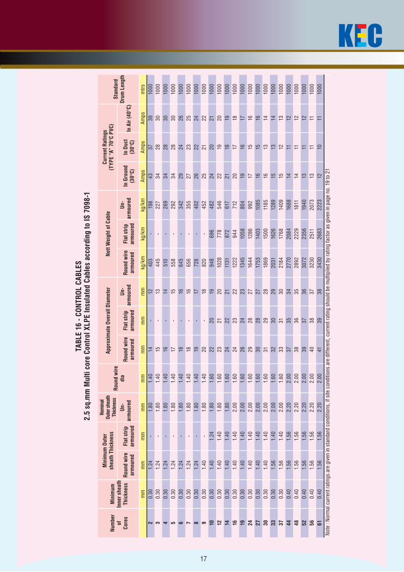
TABL
E 16
- CO
NTR
OL C
ABLE
S2.
5 sq
.mm
Mul
ti co
re C
ontr
ol X
LPE
Insu
late
d Ca
bles
acc
ordi
ng to
IS 7
098-
1
Num
ber
of
Core
s
Min
imum
In
ner s
heat
h Th
ickn
ess
Min
imum
Out
er
shea
th T
hick
ness
Nom
inal
Ou
ter s
heat
h Th
ickn
ess
Roun
d w
ire
di
a
Appr
oxim
ate
Ove
rall
Dia
met
erN
ett W
eigh
t of C
able
Curr
ent R
atin
gs
(TYP
E “A
” 70
°C P
VC)
Stan
dard
D
rum
Len
gth
Roun
d w
ire
arm
oure
dFl
at s
trip
ar
mou
red
Un-
ar
mou
red
Roun
d w
ire
arm
oure
dFl
at s
trip
ar
mou
red
Un-
ar
mou
red
Roun
d w
ire
arm
oure
dFl
at s
trip
ar
mou
red
Un-
ar
mou
red
In G
roun
d (3
0°C)
In D
uct
(30°
C)In
Air
(40°
C)
mm
mm
mm
mm
mm
mm
mm
mm
kg/k
mkg
/km
kg/k
mAm
psAm
psAm
psm
trs2
0.30
1.24
-1.
801.
4014
-12
403
-19
843
3739
1000
30.
301.
24-
1.80
1.40
15-
1344
5-
227
3428
3010
004
0.30
1.24
-1.
801.
4016
-14
510
-26
934
2830
1000
50.
301.
24-
1.80
1.40
17-
1555
8-
292
3428
3010
006
0.30
1.24
-1.
801.
4018
-16
645
-34
229
2426
1000
70.
301.
24-
1.80
1.40
18-
1665
6-
355
2723
2510
008
0.30
1.24
-1.
801.
4019
-17
728
-40
226
2224
1000
90.
301.
40-
1.80
1.40
20-
1882
0-
452
2521
2210
0010
0.30
1.40
1.24
1.80
1.60
2220
1994
869
648
224
2021
1000
120.
301.
401.
401.
801.
6023
2120
1028
778
546
2219
2010
0014
0.30
1.40
1.40
1.80
1.60
2422
2111
3187
261
721
1819
1000
160.
301.
401.
402.
001.
6024
2322
1222
944
712
2017
1810
0019
0.30
1.40
1.40
2.00
1.60
2624
2313
4510
5880
419
1617
1000
240.
301.
401.
402.
001.
6029
2827
1644
1286
992
1715
1610
0027
0.30
1.40
1.40
2.00
1.60
3028
2717
5314
0310
8516
1516
1000
300.
301.
401.
402.
001.
6031
2928
1869
1500
1185
1613
1410
0033
0.30
1.56
1.40
2.00
1.60
3230
2920
3116
2612
8915
1314
1000
370.
301.
561.
402.
001.
6033
3130
2184
1768
1409
1512
1310
0044
0.40
1.56
1.56
2.20
2.00
3735
3427
7020
8416
8814
1112
1000
480.
401.
561.
562.
202.
0038
3635
2892
2229
1811
1411
1210
0052
0.40
1.56
1.56
2.20
2.00
3937
3630
7223
5619
4013
1112
1000
560.
401.
561.
562.
202.
0040
3837
3230
2511
2073
1311
1110
0061
0.40
1.56
1.56
2.20
2.00
4139
3834
3026
8322
2312
1011
1000
Note
: No
rmal
cur
rent
ratin
gs a
re g
iven
in s
tand
ard
cond
ition
s, if
site
con
ditio
ns a
re d
iffer
ent,
curr
ent r
atin
g sh
ould
be
mul
tiplie
d by
ratin
g fa
ctor
as
give
n in
pag
e no
. 19
to 2
1
18
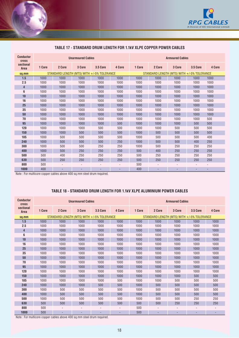
TABLE 17 - STANDARD DRUM LENGTH FOR 1.1kV XLPE COPPER POWER CABLES
Conductor cross
sectional Area
Unarmoured Cables Armoured Cables
1 Core 2 Core 3 Core 3.5 Core 4 Core 1 Core 2 Core 3 Core 3.5 Core 4 Core
sq.mm STANDARD LENGTH (MTS) WITH +/-5% TOLERANCE STANDARD LENGTH (MTS) WITH +/-5% TOLERANCE1.5 1000 1000 1000 1000 1000 1000 1000 1000 1000 10002.5 1000 1000 1000 1000 1000 1000 1000 1000 1000 10004 1000 1000 1000 1000 1000 1000 1000 1000 1000 10006 1000 1000 1000 1000 1000 1000 1000 1000 1000 100010 1000 1000 1000 1000 1000 1000 1000 1000 1000 100016 1000 1000 1000 1000 1000 1000 1000 1000 1000 100025 1000 1000 1000 1000 1000 1000 1000 1000 1000 100035 1000 1000 1000 1000 1000 1000 1000 1000 1000 100050 1000 1000 1000 1000 1000 1000 1000 1000 1000 100070 1000 1000 1000 1000 1000 1000 1000 1000 1000 50095 1000 1000 1000 1000 500 1000 1000 1000 500 500120 1000 1000 1000 500 500 1000 1000 500 500 500150 1000 1000 500 500 500 1000 500 500 500 500185 1000 500 500 500 500 1000 500 500 500 400240 1000 500 500 500 250 1000 500 500 400 250300 1000 500 500 250 250 1000 500 250 250 250400 1000 500 250 250 250 500 400 250 250 250500 500 400 250 250 250 500 250 250 250 250630 500 250 250 250 250 500 250 250 250 250800 500 - - - - 500 - - - -1000 400 - - - - 400 - - - -
Note : For multicore copper cables above 400 sq.mm steel drum required.
TABLE 18 - STANDARD DRUM LENGTH FOR 1.1kV XLPE ALUMINIUM POWER CABLES
Conductor cross
sectional Area
Unarmoured Cables Armoured Cables
1 Core 2 Core 3 Core 3.5 Core 4 Core 1 Core 2 Core 3 Core 3.5 Core 4 Core
sq.mm STANDARD LENGTH (MTS) WITH +/-5% TOLERANCE STANDARD LENGTH (MTS) WITH +/-5% TOLERANCE1.5 1000 1000 1000 1000 1000 1000 1000 1000 1000 10002.5 1000 1000 1000 1000 1000 1000 1000 1000 1000 10004 1000 1000 1000 1000 1000 1000 1000 1000 1000 10006 1000 1000 1000 1000 1000 1000 1000 1000 1000 100010 1000 1000 1000 1000 1000 1000 1000 1000 1000 100016 1000 1000 1000 1000 1000 1000 1000 1000 1000 100025 1000 1000 1000 1000 1000 1000 1000 1000 1000 100035 1000 1000 1000 1000 1000 1000 1000 1000 1000 100050 1000 1000 1000 1000 1000 1000 1000 1000 1000 100070 1000 1000 1000 1000 1000 1000 1000 1000 1000 100095 1000 1000 1000 1000 1000 1000 1000 1000 1000 1000120 1000 1000 1000 1000 1000 1000 1000 1000 1000 1000150 1000 1000 1000 1000 1000 1000 1000 1000 500 500185 1000 1000 1000 1000 500 1000 1000 500 500 500240 1000 1000 1000 500 500 1000 500 500 500 500300 1000 500 500 500 500 1000 500 500 500 500400 1000 500 500 500 500 1000 500 500 500 500500 1000 500 500 500 500 1000 500 500 250 250630 500 500 500 500 500 500 500 250 250 250800 500 - - - - 500 - - - -1000 500 - - - - 500 - - - -
Note : For multicore copper cables above 400 sq.mm steel drum required.
19
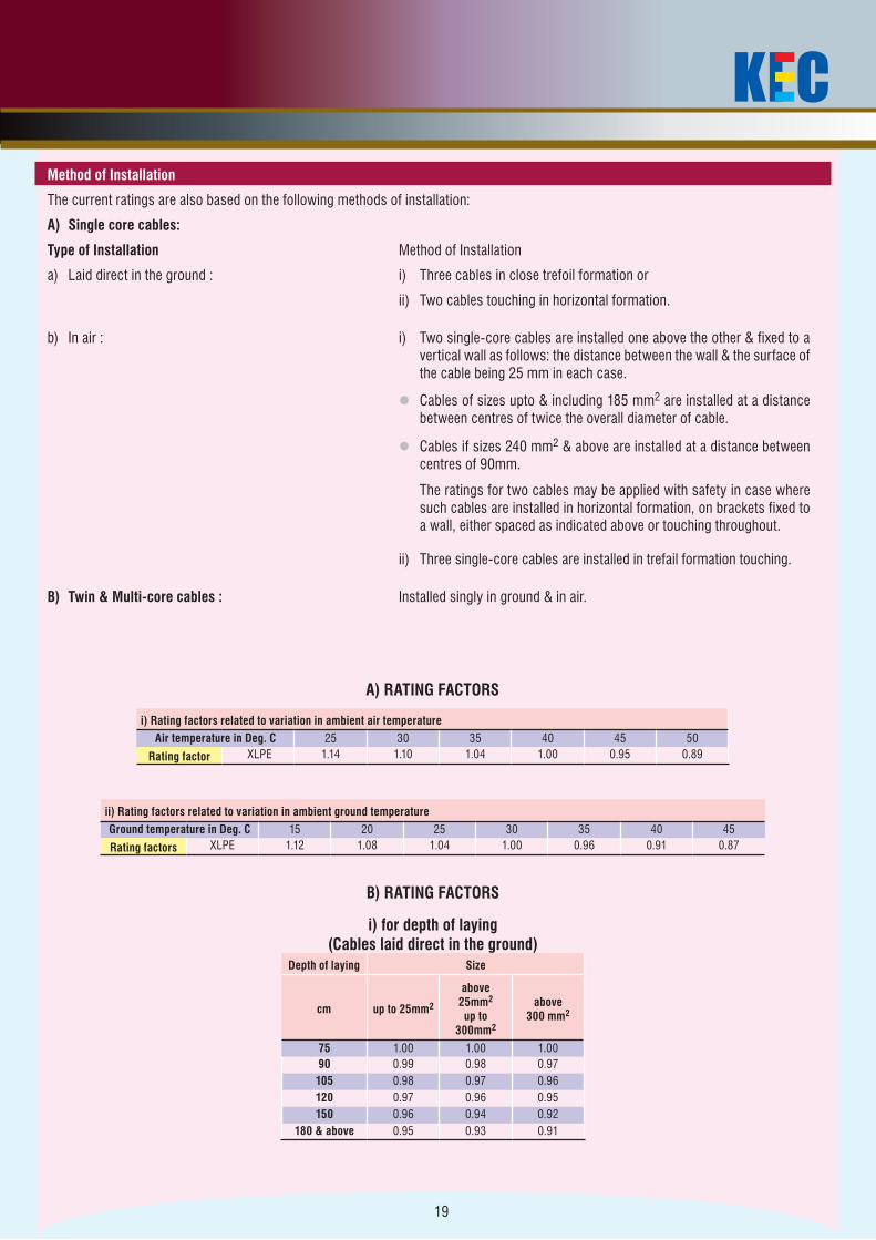
A) RATING FACTORS
i) Rating factors related to variation in ambient air temperatureAir temperature in Deg. C 25 30 35 40 45 50
Rating factor XLPE 1.14 1.10 1.04 1.00 0.95 0.89
ii) Rating factors related to variation in ambient ground temperatureGround temperature in Deg. C 15 20 25 30 35 40 45
Rating factors XLPE 1.12 1.08 1.04 1.00 0.96 0.91 0.87
B) RATING FACTORS
i) for depth of laying (Cables laid direct in the ground)
Depth of laying Size
cm up to 25mm2
above 25mm2
up to 300mm2
above 300 mm2
75 1.00 1.00 1.0090 0.99 0.98 0.97105 0.98 0.97 0.96120 0.97 0.96 0.95150 0.96 0.94 0.92
180 & above 0.95 0.93 0.91
Method of Installation
The current ratings are also based on the following methods of installation:
A) Single core cables:
Type of Installation Method of Installation
a) Laid direct in the ground : i) Three cables in close trefoil formation or
ii) Two cables touching in horizontal formation.
b) In air : i) Two single-core cables are installed one above the other & fixed to a vertical wall as follows: the distance between the wall & the surface of the cable being 25 mm in each case.
l Cables of sizes upto & including 185 mm2 are installed at a distance between centres of twice the overall diameter of cable.
l Cables if sizes 240 mm2 & above are installed at a distance between centres of 90mm.
The ratings for two cables may be applied with safety in case where such cables are installed in horizontal formation, on brackets fixed to a wall, either spaced as indicated above or touching throughout.
ii) Three single-core cables are installed in trefail formation touching.
B) Twin & Multi-core cables : Installed singly in ground & in air.
20
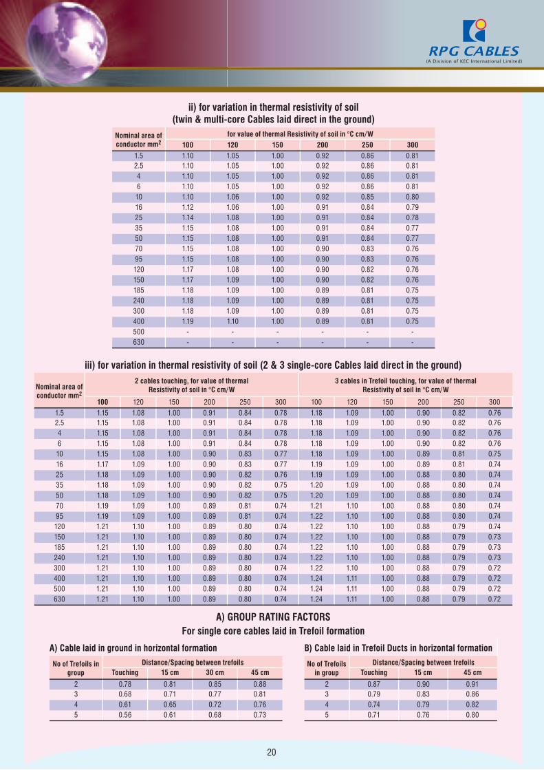
ii) for variation in thermal resistivity of soil (twin & multi-core Cables laid direct in the ground)
Nominal area of conductor mm2
for value of thermal Resistivity of soil in °C cm/W100 120 150 200 250 300
1.5 1.10 1.05 1.00 0.92 0.86 0.812.5 1.10 1.05 1.00 0.92 0.86 0.814 1.10 1.05 1.00 0.92 0.86 0.816 1.10 1.05 1.00 0.92 0.86 0.8110 1.10 1.06 1.00 0.92 0.85 0.8016 1.12 1.06 1.00 0.91 0.84 0.7925 1.14 1.08 1.00 0.91 0.84 0.7835 1.15 1.08 1.00 0.91 0.84 0.7750 1.15 1.08 1.00 0.91 0.84 0.7770 1.15 1.08 1.00 0.90 0.83 0.7695 1.15 1.08 1.00 0.90 0.83 0.76120 1.17 1.08 1.00 0.90 0.82 0.76150 1.17 1.09 1.00 0.90 0.82 0.76185 1.18 1.09 1.00 0.89 0.81 0.75240 1.18 1.09 1.00 0.89 0.81 0.75300 1.18 1.09 1.00 0.89 0.81 0.75400 1.19 1.10 1.00 0.89 0.81 0.75500 - - - - - -630 - - - - - -
iii) for variation in thermal resistivity of soil (2 & 3 single-core Cables laid direct in the ground)
Nominal area of conductor mm2
2 cables touching, for value of thermal Resistivity of soil in °C cm/W
3 cables in Trefoil touching, for value of thermalResistivity of soil in °C cm/W
100 120 150 200 250 300 100 120 150 200 250 3001.5 1.15 1.08 1.00 0.91 0.84 0.78 1.18 1.09 1.00 0.90 0.82 0.762.5 1.15 1.08 1.00 0.91 0.84 0.78 1.18 1.09 1.00 0.90 0.82 0.764 1.15 1.08 1.00 0.91 0.84 0.78 1.18 1.09 1.00 0.90 0.82 0.766 1.15 1.08 1.00 0.91 0.84 0.78 1.18 1.09 1.00 0.90 0.82 0.7610 1.15 1.08 1.00 0.90 0.83 0.77 1.18 1.09 1.00 0.89 0.81 0.7516 1.17 1.09 1.00 0.90 0.83 0.77 1.19 1.09 1.00 0.89 0.81 0.7425 1.18 1.09 1.00 0.90 0.82 0.76 1.19 1.09 1.00 0.88 0.80 0.7435 1.18 1.09 1.00 0.90 0.82 0.75 1.20 1.09 1.00 0.88 0.80 0.7450 1.18 1.09 1.00 0.90 0.82 0.75 1.20 1.09 1.00 0.88 0.80 0.7470 1.19 1.09 1.00 0.89 0.81 0.74 1.21 1.10 1.00 0.88 0.80 0.7495 1.19 1.09 1.00 0.89 0.81 0.74 1.22 1.10 1.00 0.88 0.80 0.74120 1.21 1.10 1.00 0.89 0.80 0.74 1.22 1.10 1.00 0.88 0.79 0.74150 1.21 1.10 1.00 0.89 0.80 0.74 1.22 1.10 1.00 0.88 0.79 0.73185 1.21 1.10 1.00 0.89 0.80 0.74 1.22 1.10 1.00 0.88 0.79 0.73240 1.21 1.10 1.00 0.89 0.80 0.74 1.22 1.10 1.00 0.88 0.79 0.73300 1.21 1.10 1.00 0.89 0.80 0.74 1.22 1.10 1.00 0.88 0.79 0.72400 1.21 1.10 1.00 0.89 0.80 0.74 1.24 1.11 1.00 0.88 0.79 0.72500 1.21 1.10 1.00 0.89 0.80 0.74 1.24 1.11 1.00 0.88 0.79 0.72630 1.21 1.10 1.00 0.89 0.80 0.74 1.24 1.11 1.00 0.88 0.79 0.72
A) GROUP RATING FACTORSFor single core cables laid in Trefoil formation
A) Cable laid in ground in horizontal formation B) Cable laid in Trefoil Ducts in horizontal formation
No of Trefoils in group
Distance/Spacing between trefoils No of Trefoils in group
Distance/Spacing between trefoilsTouching 15 cm 30 cm 45 cm Touching 15 cm 45 cm
2 0.78 0.81 0.85 0.88 2 0.87 0.90 0.913 0.68 0.71 0.77 0.81 3 0.79 0.83 0.864 0.61 0.65 0.72 0.76 4 0.74 0.79 0.825 0.56 0.61 0.68 0.73 5 0.71 0.76 0.80
21
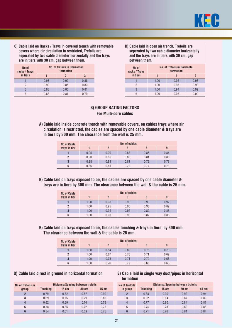
C) Cable laid on Racks / Trays in covered trench with removable covers where air circulation in restricted, Trefoils are seperated by two cable diameter horizontally and the trays are in tiers with 30 cm. gap between them.
D) Cable laid in open air trench, Trefoils are seperated by two cable diameter horizontally and the trays are in tiers with 30 cm. gap between them.
No of racks / Trays
in tiers
No. of trefoils in Horizontal formation
No of racks / Trays
in tiers
No. of trefoils in Horizontal formation
1 2 3 1 2 3
1 0.95 0.90 0.88 1 1.00 0.98 0.962 0.90 0.85 0.83 2 1.00 0.95 0.933 0.88 0.83 0.81 3 1.00 0.94 0.926 0.86 0.81 0.79 6 1.00 0.93 0.90
B) GROUP RATING FACTORS
For Multi-core cables
A) Cable laid inside concrete trench with removable covers, on cables trays where air circulation is restricted, the cables are spaced by one cable diameter & trays are in tiers by 300 mm. The clearance from the wall is 25 mm.
No of Cable trays in tier
No. of cables1 2 3 6 9
1 0.95 0.90 0.88 0.85 0.842 0.90 0.85 0.83 0.81 0.803 0.88 0.83 0.81 0.79 0.786 0.86 0.81 0.79 0.77 0.76
B) Cable laid on trays exposed to air, the cables are spaced by one cable diameter & trays are in tiers by 300 mm. The clearance between the wall & the cable is 25 mm.
No of Cable trays in tier
No. of cables1 2 3 6 9
1 1.00 0.98 0.96 0.93 0.922 1.00 0.95 0.93 0.90 0.893 1.00 0.94 0.92 0.89 0.886 1.00 0.93 0.90 0.87 0.86
B) Cable laid on trays exposed to air, the cables touching & trays in tiers by 300 mm. The clearance between the wall & the cable is 25 mm.
No of Cable trays in tier
No. of cables1 2 3 6 9
1 1.00 0.84 0.80 0.75 0.732 1.00 0.87 0.76 0.71 0.693 1.00 0.78 0.74 0.70 0.686 1.00 0.76 0.72 0.68 0.66
D) Cable laid direct in ground in horizontal formation E) Cable laid in single way duct/pipes in horizontal formation
No of Trefoils in group
Distance/Spacing between trefoils No of Trefoils in group
Distance/Spacing between trefoilsTouching 15 cm 30 cm 45 cm Touching 15 cm 30 cm 45 cm
2 0.79 0.82 0.87 0.90 2 0.88 0.90 0.92 0.943 0.69 0.75 0.79 0.83 3 0.82 0.84 0.87 0.894 0.62 0.69 0.74 0.79 4 0.77 0.80 0.84 0.875 0.58 0.65 0.72 0.76 5 0.74 0.78 0.82 0.856 0.54 0.61 0.69 0.75 6 0.71 0.76 0.81 0.84
22
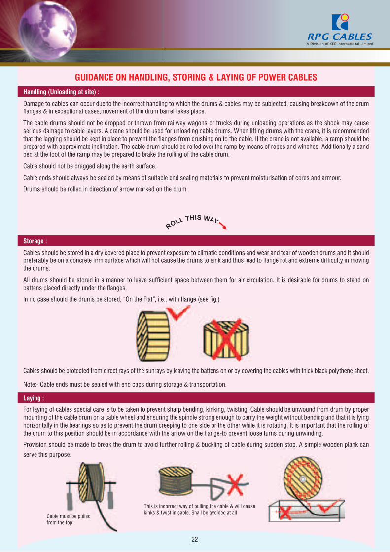
GUIDANCE ON HANDLING, STORING & LAYING OF POWER CABLESHandling (Unloading at site) :
Damage to cables can occur due to the incorrect handling to which the drums & cables may be subjected, causing breakdown of the drum flanges & in exceptional cases,movement of the drum barrel takes place.
The cable drums should not be dropped or thrown from railway wagons or trucks during unloading operations as the shock may cause serious damage to cable layers. A crane should be used for unloading cable drums. When lifting drums with the crane, it is recommended that the lagging should be kept in place to prevent the flanges from crushing on to the cable. If the crane is not available, a ramp should be prepared with approximate inclination. The cable drum should be rolled over the ramp by means of ropes and winches. Additionally a sand bed at the foot of the ramp may be prepared to brake the rolling of the cable drum.
Cable should not be dragged along the earth surface.
Cable ends should always be sealed by means of suitable end sealing materials to prevant moisturisation of cores and armour.
Drums should be rolled in direction of arrow marked on the drum.
Storage :
Cables should be stored in a dry covered place to prevent exposure to climatic conditions and wear and tear of wooden drums and it should preferably be on a concrete firm surface which will not cause the drums to sink and thus lead to flange rot and extreme difficulty in moving the drums.
All drums should be stored in a manner to leave sufficient space between them for air circulation. It is desirable for drums to stand on battens placed directly under the flanges.
In no case should the drums be stored, “On the Flat”, i.e., with flange (see fig.)
Cables should be protected from direct rays of the sunrays by leaving the battens on or by covering the cables with thick black polythene sheet.
Note:- Cable ends must be sealed with end caps during storage & transportation.
Laying :
For laying of cables special care is to be taken to prevent sharp bending, kinking, twisting. Cable should be unwound from drum by proper mounting of the cable drum on a cable wheel and ensuring the spindle strong enough to carry the weight without bending and that it is lying horizontally in the bearings so as to prevent the drum creeping to one side or the other while it is rotating. It is important that the rolling of the drum to this position should be in accordance with the arrow on the flange-to prevent loose turns during unwinding.
Provision should be made to break the drum to avoid further rolling & buckling of cable during sudden stop. A simple wooden plank can
serve this purpose.
Cable must be pulledfrom the top
This is incorrect way of pulling the cable & will causekinks & twist in cable. Shall be avoided at all
23
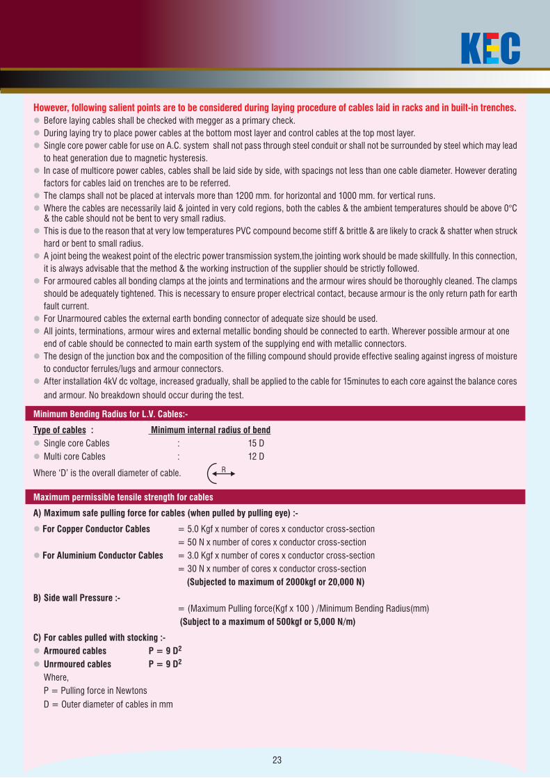
However, following salient points are to be considered during laying procedure of cables laid in racks and in built-in trenches.l Before laying cables shall be checked with megger as a primary check. l During laying try to place power cables at the bottom most layer and control cables at the top most layer.l Single core power cable for use on A.C. system shall not pass through steel conduit or shall not be surrounded by steel which may lead to heat generation due to magnetic hysteresis.l In case of multicore power cables, cables shall be laid side by side, with spacings not less than one cable diameter. However derating factors for cables laid on trenches are to be referred.l The clamps shall not be placed at intervals more than 1200 mm. for horizontal and 1000 mm. for vertical runs.l Where the cables are necessarily laid & jointed in very cold regions, both the cables & the ambient temperatures should be above 0°C
& the cable should not be bent to very small radius.l This is due to the reason that at very low temperatures PVC compound become stiff & brittle & are likely to crack & shatter when struck hard or bent to small radius.l A joint being the weakest point of the electric power transmission system,the jointing work should be made skillfully. In this connection, it is always advisable that the method & the working instruction of the supplier should be strictly followed.l For armoured cables all bonding clamps at the joints and terminations and the armour wires should be thoroughly cleaned. The clamps should be adequately tightened. This is necessary to ensure proper electrical contact, because armour is the only return path for earth fault current. l For Unarmoured cables the external earth bonding connector of adequate size should be used. l All joints, terminations, armour wires and external metallic bonding should be connected to earth. Wherever possible armour at one end of cable should be connected to main earth system of the supplying end with metallic connectors.l The design of the junction box and the composition of the filling compound should provide effective sealing against ingress of moisture to conductor ferrules/lugs and armour connectors. l After installation 4kV dc voltage, increased gradually, shall be applied to the cable for 15minutes to each core against the balance cores
and armour. No breakdown should occur during the test.
Minimum Bending Radius for L.V. Cables:-
Type of cables : Minimum internal radius of bendl Single core Cables : 15 Dl Multi core Cables : 12 D
Where ‘D’ is the overall diameter of cable.
R
Maximum permissible tensile strength for cables
A) Maximum safe pulling force for cables (when pulled by pulling eye) :-
l For Copper Conductor Cables = 5.0 Kgf x number of cores x conductor cross-section = 50 N x number of cores x conductor cross-sectionl For Aluminium Conductor Cables = 3.0 Kgf x number of cores x conductor cross-section = 30 N x number of cores x conductor cross-section (Subjected to maximum of 2000kgf or 20,000 N)
B) Side wall Pressure :- = (Maximum Pulling force(Kgf x 100 ) /Minimum Bending Radius(mm) (Subject to a maximum of 500kgf or 5,000 N/m)
C) For cables pulled with stocking :-l Armoured cables P = 9 D2
l Unrmoured cables P = 9 D2
Where, P = Pulling force in Newtons D = Outer diameter of cables in mm
24
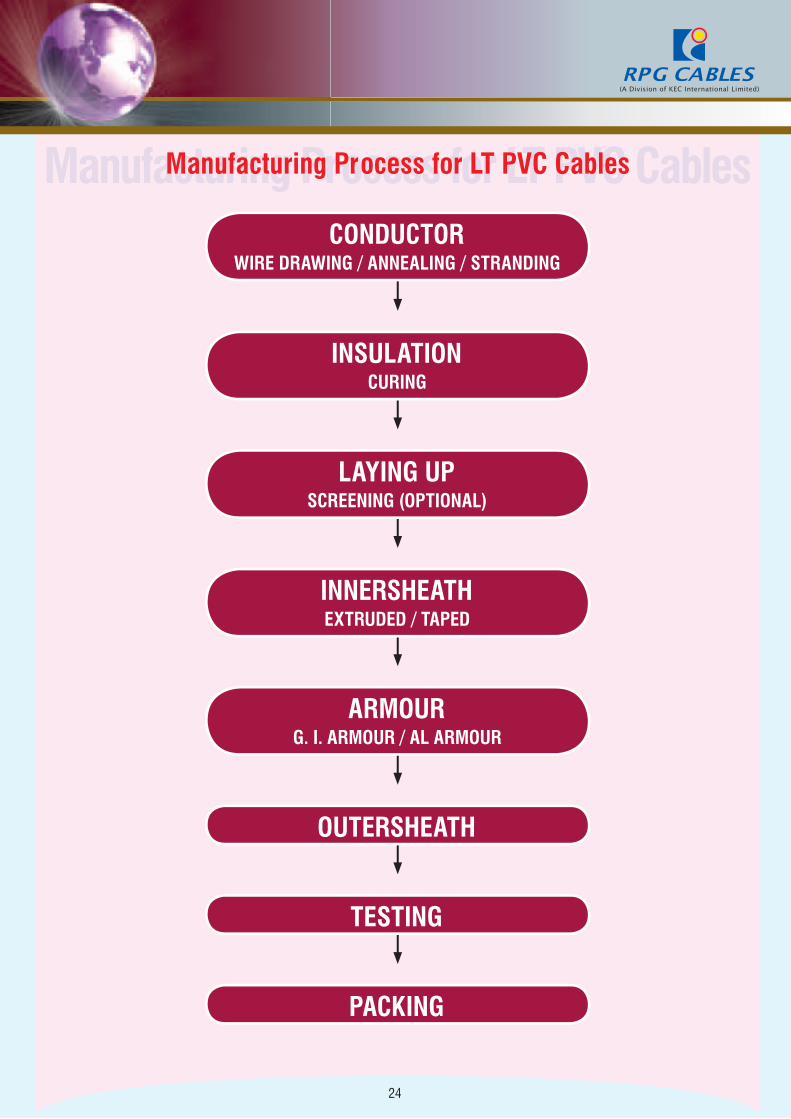
Manufacturing Process for LT PVC CablesManufacturing Process for LT PVC Cables
CONDUCTORWIRE DRAWING / ANNEALING / STRANDING
LAYING UPSCREENING (OPTIONAL)
INSULATIONCURING
INNERSHEATHEXTRUDED / TAPED
ARMOURG. I. ARMOUR / AL ARMOUR
OUTERSHEATH
TESTING
PACKING

KEC is one of the oldest players in the industry and global leader in the Infrastructure Engineering, Procurement and Construction space. Established in 1945, KEC has a signifcant presence in the segments of Power Transmission & Distribution, Cabling, Railway, Telecom and Water Resource management. KEC’s strengths lie in Engineering, Design, Manufacture and Testing, supply of transmission towers, telecom towers, cables and Construction of turnkey infrastructure projects. KEC’s focused approach towards project management enables the creation of world class products, innovative solutions, customized to overcome extreme terrain and climate. With proven technical process in handling mega projects and superior project management expertise, KEC has made an indelible mark on the world map by constantly and consistently reengineering itselfto retain its position of leadership in the areas of quality, technology, capacity and capability.
RPG Enterprises is one of India’s largest business conglomerates. Since its inception in 1979, RPG Enterprises has been one of the fastest growing business houses in India. RPG Enterprises has diverse businesses under its fold ranging from Power, Tyres, Infrastructure, IT to Pharma. The Group’s management comprises individuals extensively qualifed and experienced in their domain areas. RPG’s wide ranging business invite growing returns and high esteem in the eyes of all its stakeholders. The Group lives by values of keen entrepreneurial skills, performance and excellence.
Corporate Office6th Floor, RPG House, 463. Dr. Annie Besant Road, Worli, Mumbai - 400 030, India. Tel.: +91-22-66670300, 24937244 I Fax : +91-22-24930206email : [email protected] I [email protected] I [email protected]
WorksThane : II Pokharan Road, PB No. 11, Thane, Pin - 400 601, Maharashtra, India.Silvassa : Plot No. 273/4, Demni Road, Dadra, Silvassa, Pin - 396 193, UT of D & NH, India.Mysore : 349/350, Hebbal Industrial Area, Hootgalli, Belavadi Post, Mysore, Pin - 570 018, Karnataka, India.
Sales Offices
DelhiZensar Business Centre | N-83,1st Floor (Above PNB), Connaught Place,New Delhi - 110 001, India.Tel. : +91-11-66098599 Fax : +91-11-66098597
Mumbai6th Floor, RPG House, 463. Dr. Annie Besant Road, Worli, Mumbai - 400 030, India.Tel. : +91-22-66670300, 24937244 Fax : +91-22-24930206
PuneFlat No.9, “KSHITIJ”,1 st Floor, 769/6, Lane No.7, Prabhat Road, Deccan Gymkhana, Pune - 411 004, India. Tel. : +91-20-64706061, 6065Fax : +91-20-25650414
ChennaiBhavani Mansion No.3, 4th Lane, Nungambakkam High Road, Chennai - 600 034, India.Tel. : +91-44-28332920, 28332918 Fax : +91-44-28332917
KolkataHalwasiya Mansion, Ground Floor, 6/2, Moira Street,Kolkata - 700 017, India.Tel. : +91-33-64590654Fax : +91-33-22906720
VadodaraA-304, Siddhi Vinayak Complex, Faramji Compound, Bh. Rly. Station,Alkapuri, Vadodara - 390 007, India. Tel. : +91-265-3015454 Fax : +91-265-3015454
Hyderabad406 & 407, Maheshwari Chambers, Erramanzil, Somajiguda,Hyderabad - 500 082, India. Tel. : +91-40-30901642 Fax : +91-40-30901642
BangaloreC/o. CEAT Limited, Jasmine Mansion, 4th Floor, 19, J. C. Road,Bangalore - 560 002, India. Tel. : +91-80-22124444 Fax : +91-80-22124444
MA
NG
AL
AM
M :
+91
9820
3 48
854
July 2011


![Accounting] Vedika Software - Accounting User Guide (1998)](https://img.pdfslide.net/doc/110x75/546b5df0af795985298b4b6b/accounting-vedika-software-accounting-user-guide-1998.jpg)