Embed Size (px)
Citation preview
EEDEN07-430
technical dataA
pplied Systems
Air-cooled
EWYQ080-250DAYN

ÈEEDEN07-430^ËÍ
Daikin Europe N.V. is approved by LRQA for itsQuality Management System in accordance with theISO9001 standard. ISO9001 pertains to qualityassurance regarding design, development,manufacturing as well as to services related to theproduct.
Daikin units comply with the European regulations that guarantee the safety of the product.
The present publication is drawn up by way of information only anddoes not constitute an offer binding upon Daikin Europe N.V.. DaikinEurope N.V. has compiled the content of this publication to the bestof its knowledge. No express or implied warranty is given for thecompleteness, accuracy, reliability or fitness for particular purpose ofits content and the products and services presented therein.Specifications are subject to change without prior notice. DaikinEurope N.V. explicitly rejects any liability for any direct or indirectdamage, In the broadest sense, arising from or related to the useand/or interpretation of this publication. All content is copyrighted byDaikin Europe N.V..
Daikin Europe N.V. is participating in the EUROVENTCertification Programme. Products are as listed in theEUROVENT Directory of Certified Products.
Naamloze VennootschapZandvoordestraat 300B-8400 Oostende, Belgiumwww.daikin.euBTW: BE 0412 120 336RPR Oostende
Daikin’s unique position as a manufacturer of airconditioning equipment, compressors andrefrigerants has led to its close involvement inenvironmental issues. For several years Daikinhas had the intension to become a leader in theprovision of products that have limited impacton the environment. This challenge demandsthe eco design and development of a widerange of products and an energy managementsystem, resulting in energy conservation and areduction of waste. ISO14001 assures an effective environmental
management system in order to help protecthuman•health•and the environment from thepotential impact of our activities, products andservices and to assist in maintaining and improvingthe quality of the•environment.
Air-cooledEWYQ080-250DAYN
EED
EN07
-430
• 0
5/20
07 •
Cop
yrig
ht ©
Dai
kin
Prep
ared
in B
elgi
um b
y La
nnoo
(w
ww
.lann
oopr
int.b
e), a
com
pany
who
se c
once
rn f
or
the
envi
ronm
ont
is se
t in
the
EM
AS
and
ISO
140
01 s
yste
ms.
Res
pons
ible
Edi
tor:
Dai
kin
Euro
pe N
.V.,
Zand
voor
dest
raat
300
, B-8
400
oost
ende
EEDEN07-430
technical dataA
pplied Systems
Air-cooled
EWYQ080-250DAYN

• Chillers • R-410A • EWYQ-DAYN
1
• Applied Systems • Chillers
Chillers Applied Sys EWTP-MBY R-407C
Cooling only
Heating only
Heat pump
• Applied Systems • Chillers 1
• Chillers • R-410A • EWYQ-DAYN
TABLE OF CONTENTSEWYQ-DAYN
1 Features . . . . . . . . . . . . . . . . . . . . . . . . . . . . . . . . . . . . . . . . . . . . . . . . . . . . . . . . . . . . . 2
2 Specifications text . . . . . . . . . . . . . . . . . . . . . . . . . . . . . . . . . . . . . . . . . . . . . . . . . . 3
3 Specifications . . . . . . . . . . . . . . . . . . . . . . . . . . . . . . . . . . . . . . . . . . . . . . . . . . . . . . . 5Technical Specifications . . . . . . . . . . . . . . . . . . . . . . . . . . . . . . . . . . . . . . . . . . . . . 5Electrical Specifications . . . . . . . . . . . . . . . . . . . . . . . . . . . . . . . . . . . . . . . . . . . . . . 6Specifications (options) . . . . . . . . . . . . . . . . . . . . . . . . . . . . . . . . . . . . . . . . . . . . . . 8
4 Options . . . . . . . . . . . . . . . . . . . . . . . . . . . . . . . . . . . . . . . . . . . . . . . . . . . . . . . . . . . . . 12
5 Capacity tables . . . . . . . . . . . . . . . . . . . . . . . . . . . . . . . . . . . . . . . . . . . . . . . . . . . . 13Cooling capacity tables . . . . . . . . . . . . . . . . . . . . . . . . . . . . . . . . . . . . . . . . . . . . . 13Heating capacity tables . . . . . . . . . . . . . . . . . . . . . . . . . . . . . . . . . . . . . . . . . . . . . 14
6 Dimensional drawing & centre of gravity . . . . . . . . . . . . . . . . . . . . . . . 15Dimensional drawing . . . . . . . . . . . . . . . . . . . . . . . . . . . . . . . . . . . . . . . . . . . . . . . . 15
7 Piping diagram. . . . . . . . . . . . . . . . . . . . . . . . . . . . . . . . . . . . . . . . . . . . . . . . . . . . . 19
8 Wiring diagram. . . . . . . . . . . . . . . . . . . . . . . . . . . . . . . . . . . . . . . . . . . . . . . . . . . . . 23External connection diagram . . . . . . . . . . . . . . . . . . . . . . . . . . . . . . . . . . . . . . . . 23
9 Sound data . . . . . . . . . . . . . . . . . . . . . . . . . . . . . . . . . . . . . . . . . . . . . . . . . . . . . . . . . 24Sound power spectrum . . . . . . . . . . . . . . . . . . . . . . . . . . . . . . . . . . . . . . . . . . . . . 24
10 Installation . . . . . . . . . . . . . . . . . . . . . . . . . . . . . . . . . . . . . . . . . . . . . . . . . . . . . . . . . . 25Fixation and foundation of units . . . . . . . . . . . . . . . . . . . . . . . . . . . . . . . . . . . . . 25Water charge, flow and quality . . . . . . . . . . . . . . . . . . . . . . . . . . . . . . . . . . . . . . 28
11 Operation range . . . . . . . . . . . . . . . . . . . . . . . . . . . . . . . . . . . . . . . . . . . . . . . . . . . 29
12 Hydraulic performance. . . . . . . . . . . . . . . . . . . . . . . . . . . . . . . . . . . . . . . . . . . . 31Water pressure drop curve evaporator . . . . . . . . . . . . . . . . . . . . . . . . . . . . . . 31Static pressure drop unit . . . . . . . . . . . . . . . . . . . . . . . . . . . . . . . . . . . . . . . . . . . . 34
• Chillers • R-410A • EWYQ-DAYN
11
2
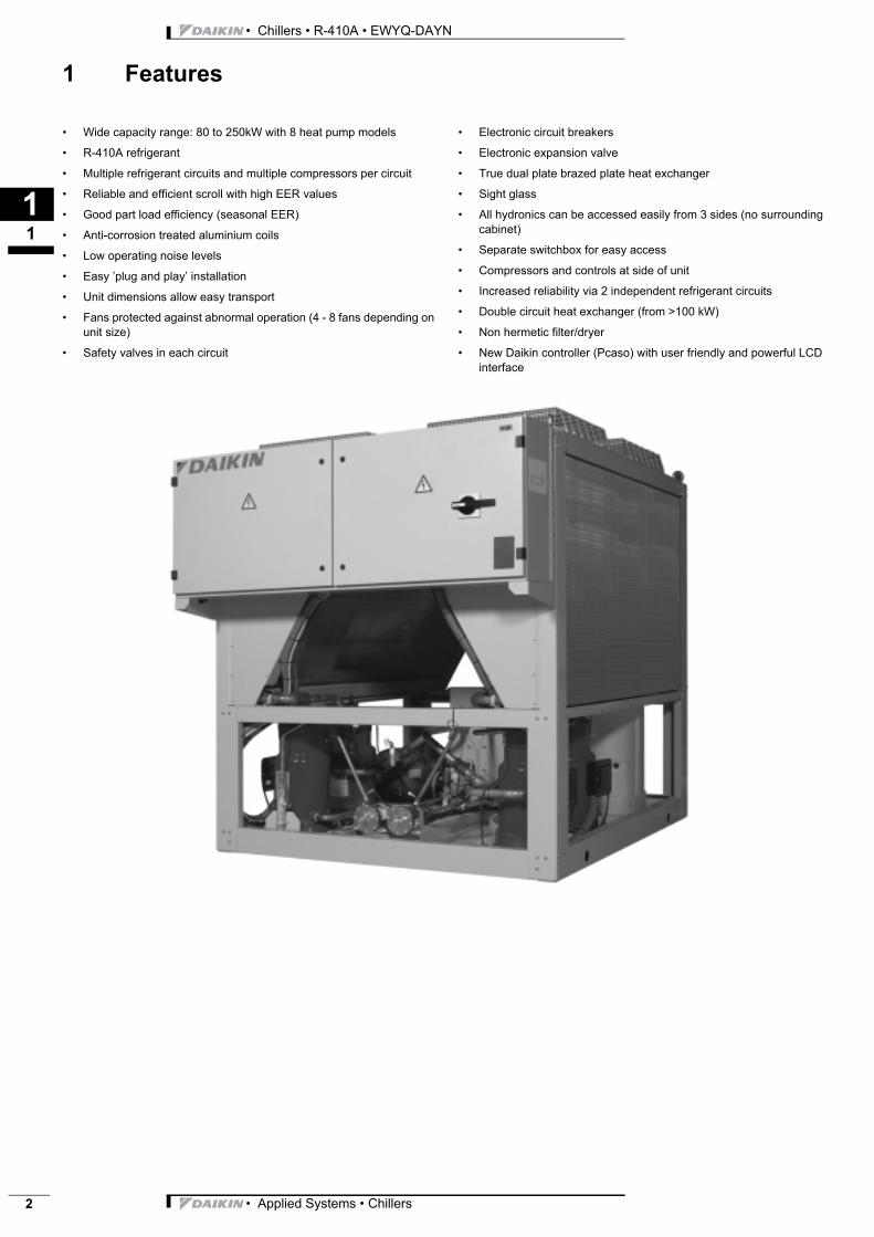
1 Features
llers lied Sys Q-DAYN 10A
Chi App EWY R-4 • Wide capacity range: 80 to 250kW with 8 heat pump models• R-410A refrigerant
• Multiple refrigerant circuits and multiple compressors per circuit
• Reliable and efficient scroll with high EER values
• Good part load efficiency (seasonal EER)
• Anti-corrosion treated aluminium coils
• Low operating noise levels
• Easy ’plug and play’ installation
• Unit dimensions allow easy transport
• Fans protected against abnormal operation (4 - 8 fans depending on unit size)
• Safety valves in each circuit
• Electronic circuit breakers
• Electronic expansion valve
• True dual plate brazed plate heat exchanger
• Sight glass
• All hydronics can be accessed easily from 3 sides (no surrounding cabinet)
• Separate switchbox for easy access
• Compressors and controls at side of unit
• Increased reliability via 2 independent refrigerant circuits
• Double circuit heat exchanger (from >100 kW)
• Non hermetic filter/dryer
• New Daikin controller (Pcaso) with user friendly and powerful LCD interface
• Applied Systems • Chillers
3
12
• Chillers • R-410A • EWYQ-DAYN
2 Specifications text
EWYQ080-250DAYN
Unit construction
Compact, modular and weatherproof design air-cooled chiller for outdoor installation - manufactured according to the
ISO 9001 quality standard.
The ready-to-connect range has been designed for both air conditioning and process cooling applications and meets
PED conformity. The use of state-of-the-art technologies and high quality materials ensures efficiency, reliability and an
extended service life.
Each chiller is subjected to a function test and test run in the factory allowing for standard requirements.
Casing / Colour
Painted, galvanised steel plate. Fully factory assembled on a base frame. Colour ivory white.
Number of refrigerant circuits
Size 080-100 single circuit, 130-250 double circuit.
Each refrigerant circuit has its own fully independent design thereby guaranteeing a high level of system reliability.
Compressor
Hermetically sealed scroll type compressor with low level of vibration.
Condenser
Condensation register with continuous running and surface-corrugated aluminium flaps. The seamless copper pipes are
permanently connected with the flaps by means of mechanical flaring. The refrigerant subcooler to improve
performance is an integral part of each refrigerant circuit with a liquid stopper between the condenser and subcooler
circuit. An epoxy resin coating permanently protects the flaps from corrosion thereby extending the field of application of
this device.
Fans
Low-noise axial fans complete with outlet protective grating, directly driven, statically and dynamically balanced,
weatherproof drive motors for outdoor operation and maintenance-free bearings. Motor safety class IP 55. Winter
starting device for operating the machine down to minimum exterior temperatures of 0°C as standard. Optional inverter
fans controlled on high pressure allow ambient operation down to -10°C.
Evaporator
R410a optimised DX counter flow plate heat exchanger made of stainless steel, plates brazed gastight with copper, for
water and glycol mixtures. As from module size 130 twin circuit design (two refrigerant circuits / one water circuit). A
special refrigerant distribution system has been incorporated into the plate duct for optimal capacity of the complete
heat transmission surface. As well as an additional increase in efficiency, this is also responsible for stable control
behaviour in the heat exchanger. The plate heat exchanger is heat-insulated to ensure it is diffusion-proof to prevent
any heat loss.
Piping
Refrigerant connecting conduits made of Cu pipe with the required cooling fixtures such as shut-off and filler valves,
filter-driers, solenoid valve and expansion valve. Suction line including insulation. Refrigerant circuit is subjected to a
pressure and leak test in the factory, is dried, evacuated and supplied with refrigerant and filled with oil ready for
operation.
Hydraulic module
To be able to cover a larger range of applications, the EWYQ060-250DAYN range can be supplied with or without
integrated hydraulic components. The basic unit already contains the flow switch and water filter. The optional hydraulic
module includes all components needed for operation as well as a circulation pump, expansion vessel, manometer,
• Applied Systems • Chillers 3
• Chillers • R-410A • EWYQ-DAYN
12
4
2 Specifications text
shut-off valves, safety valve, purge, filling and drainage valve, maintenance connections and regulation valve.
Furthermore the chiller can be expanded with a 200l buffer tank within the chassis.
Switching and control device
Weatherproof design factory-wired control cabinet, safety class IP54, assembled externally on the machine chassis,
with all the components required for automatic operation consisting specifically of the following:
Main switch, phase-sequence relay, transformer (400/230V), compressor start-up protective devices with fuse and heat
overload cut-out for the fans, control voltage fuse, designated terminal strip for external connections.
PCAS0 digital microprocessor for controlling the cold water flow temperature using PID control behaviour without
continuous control deviation with the following sensors:
• Temperature sensor in the cold water flow and return
• Temperature sensor for evaporation and condensation temperature
• Low- and high-pressure switch
The controller has the following functions to prevent safety shut-downs:
Load limiting controller for low evaporation and high condensation temperature to prevent overloading the compressor
motor and high- and low-pressure faults.
Self-adjusting start-up frequency limiting with automated equalisation of compressor hours and operating hours.
All of the operating and status data can be read on the LC display and the set points can be set. In particular, these are:
• Cold water set point
• Cold water outlet temperature
• Air temperature
• Operating hours and start of each compressor
• the last 40 error messages complete with date and time
• Evaporation and condensation temperature for each refrigerant circuit
As standard, the machine has communication facilities with higher level master systems in which case the following
contacts are executed or can be executed:
Inputs:
• Sliding movement of set points
• Remote On/Off
• External alarm acknowledgement
Outputs:
• Collection fault message circuit 1
• Collection fault message circuit 2
• Control of third party free cooler
DICN can be offered as optional extra to sequence upto 4 units, offering accurate control of a common setpoint
temperature, pump management and balanced compressor run hours.
Modbus is the standard communication protocol for BMS. As an option a gateway allows Lonworks or Bacnet
communication. Daikin DIII net offers further communication possibilities with Daikin D-Bacs systems such as I-
Manager and I-Touch controller.
• Applied Systems • Chillers
3
13
• Chillers • R-410A • EWYQ-DAYN
3 Specifications
3-1 TECHNICAL SPECIFICATIONSEWYQ080DA
YNEWYQ100DA
YNEWYQ130DA
YNEWYQ150DA
YNEWYQ180DA
YNEWYQ210DA
YNEWYQ230DA
YNEWYQ250DA
YN
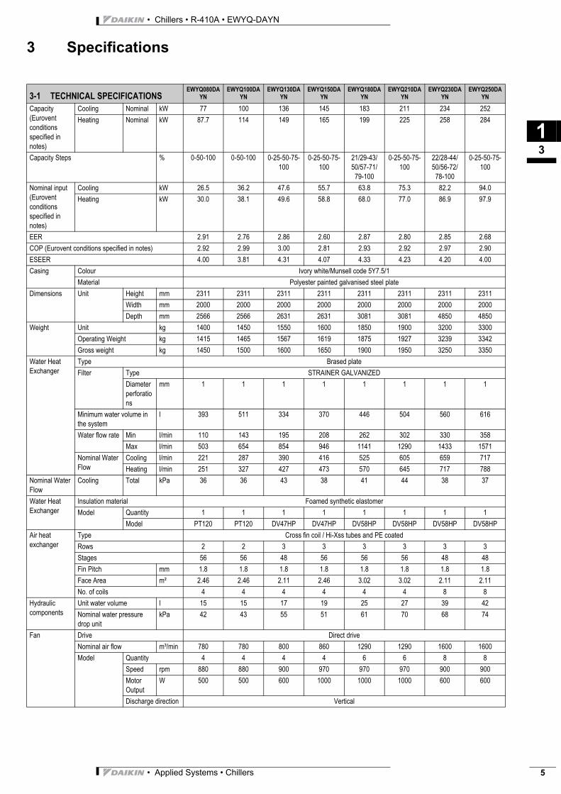
Capacity (Eurovent conditions specified in notes)
Cooling Nominal kW 77 100 136 145 183 211 234 252Heating Nominal kW 87.7 114 149 165 199 225 258 284
Capacity Steps % 0-50-100 0-50-100 0-25-50-75-100
0-25-50-75-100
21/29-43/50/57-71/
79-100
0-25-50-75-100
22/28-44/50/56-72/
78-100
0-25-50-75-100
Nominal input (Eurovent conditions specified in notes)
Cooling kW 26.5 36.2 47.6 55.7 63.8 75.3 82.2 94.0Heating kW 30.0 38.1 49.6 58.8 68.0 77.0 86.9 97.9
EER 2.91 2.76 2.86 2.60 2.87 2.80 2.85 2.68COP (Eurovent conditions specified in notes) 2.92 2.99 3.00 2.81 2.93 2.92 2.97 2.90ESEER 4.00 3.81 4.31 4.07 4.33 4.23 4.20 4.00Casing Colour Ivory white/Munsell code 5Y7.5/1
Material Polyester painted galvanised steel plateDimensions Unit Height mm 2311 2311 2311 2311 2311 2311 2311 2311
Width mm 2000 2000 2000 2000 2000 2000 2000 2000Depth mm 2566 2566 2631 2631 3081 3081 4850 4850
Weight Unit kg 1400 1450 1550 1600 1850 1900 3200 3300Operating Weight kg 1415 1465 1567 1619 1875 1927 3239 3342Gross weight kg 1450 1500 1600 1650 1900 1950 3250 3350
Water Heat Exchanger
Type Brased plateFilter Type STRAINER GALVANIZED
Diameter perforations
mm 1 1 1 1 1 1 1 1
Minimum water volume in the system
l 393 511 334 370 446 504 560 616
Water flow rate Min l/min 110 143 195 208 262 302 330 358Max l/min 503 654 854 946 1141 1290 1433 1571
Nominal Water Flow
Cooling l/min 221 287 390 416 525 605 659 717Heating l/min 251 327 427 473 570 645 717 788
Nominal Water Flow
Cooling Total kPa 36 36 43 38 41 44 38 37
Water Heat Exchanger
Insulation material Foamed synthetic elastomerModel Quantity 1 1 1 1 1 1 1 1
Model PT120 PT120 DV47HP DV47HP DV58HP DV58HP DV58HP DV58HPAir heat exchanger
Type Cross fin coil / Hi-Xss tubes and PE coatedRows 2 2 3 3 3 3 3 3Stages 56 56 48 56 56 56 48 48Fin Pitch mm 1.8 1.8 1.8 1.8 1.8 1.8 1.8 1.8Face Area m² 2.46 2.46 2.11 2.46 3.02 3.02 2.11 2.11No. of coils 4 4 4 4 4 4 8 8
Hydraulic components
Unit water volume l 15 15 17 19 25 27 39 42Nominal water pressure drop unit
kPa 42 43 55 51 61 70 68 74
Fan Drive Direct driveNominal air flow m³/min 780 780 800 860 1290 1290 1600 1600Model Quantity 4 4 4 4 6 6 8 8
Speed rpm 880 880 900 970 970 970 900 900Motor Output
W 500 500 600 1000 1000 1000 600 600
Discharge direction Vertical
• Applied Systems • Chillers 5
• Chillers • R-410A • EWYQ-DAYN
13
6
3 Specifications
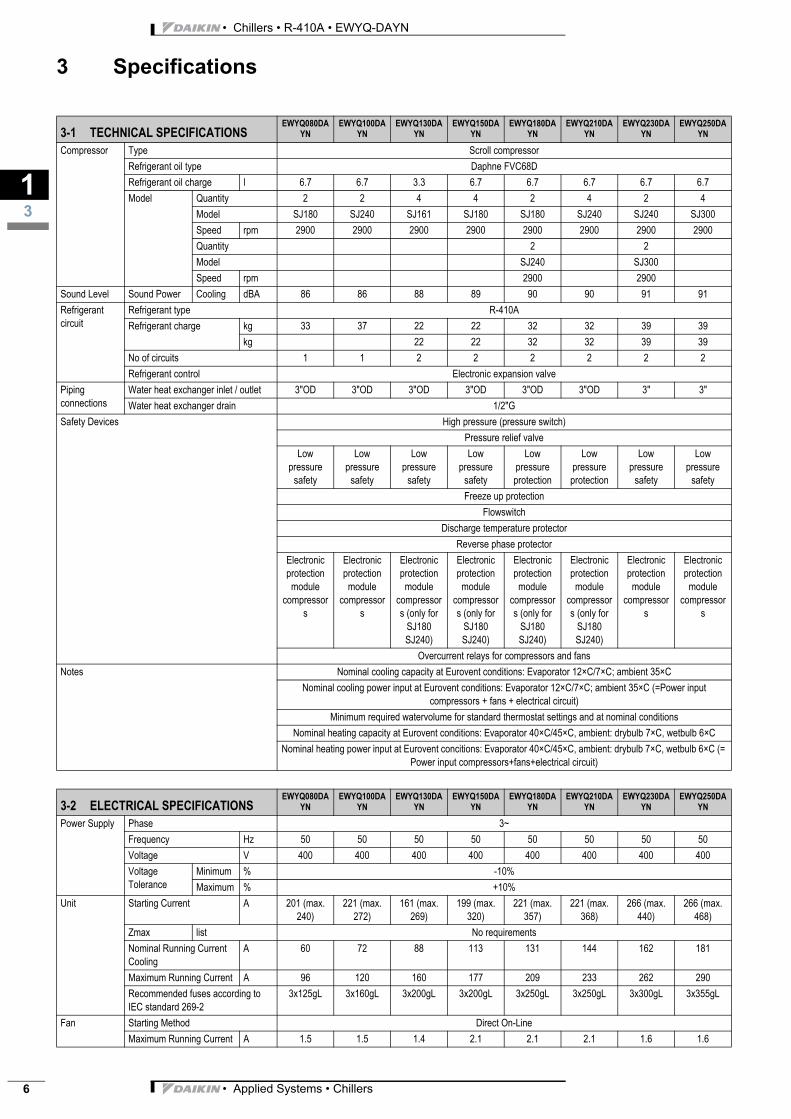
Compressor Type Scroll compressorRefrigerant oil type Daphne FVC68DRefrigerant oil charge l 6.7 6.7 3.3 6.7 6.7 6.7 6.7 6.7Model Quantity 2 2 4 4 2 4 2 4
Model SJ180 SJ240 SJ161 SJ180 SJ180 SJ240 SJ240 SJ300Speed rpm 2900 2900 2900 2900 2900 2900 2900 2900Quantity 2 2Model SJ240 SJ300Speed rpm 2900 2900
Sound Level Sound Power Cooling dBA 86 86 88 89 90 90 91 91Refrigerant circuit
Refrigerant type R-410ARefrigerant charge kg 33 37 22 22 32 32 39 39
kg 22 22 32 32 39 39No of circuits 1 1 2 2 2 2 2 2Refrigerant control Electronic expansion valve
Piping connections
Water heat exchanger inlet / outlet 3"OD 3"OD 3"OD 3"OD 3"OD 3"OD 3" 3"Water heat exchanger drain 1/2"G
Safety Devices High pressure (pressure switch)Pressure relief valve
Low pressure
safety
Low pressure
safety
Low pressure
safety
Low pressure
safety
Low pressure protection
Low pressure protection
Low pressure
safety
Low pressure
safetyFreeze up protection
FlowswitchDischarge temperature protector
Reverse phase protectorElectronic protection module
compressors
Electronic protection
module compressor
s
Electronic protection
module compressors (only for
SJ180 SJ240)
Electronic protection module
compressors (only for
SJ180 SJ240)
Electronic protection
module compressors (only for
SJ180 SJ240)
Electronic protection
module compressors (only for
SJ180 SJ240)
Electronic protection
module compressor
s
Electronic protection
module compressor
s
Overcurrent relays for compressors and fansNotes Nominal cooling capacity at Eurovent conditions: Evaporator 12×C/7×C; ambient 35×C
Nominal cooling power input at Eurovent conditions: Evaporator 12×C/7×C; ambient 35×C (=Power input compressors + fans + electrical circuit)
Minimum required watervolume for standard thermostat settings and at nominal conditionsNominal heating capacity at Eurovent conditions: Evaporator 40×C/45×C, ambient: drybulb 7×C, wetbulb 6×C
Nominal heating power input at Eurovent concitions: Evaporator 40×C/45×C, ambient: drybulb 7×C, wetbulb 6×C (= Power input compressors+fans+electrical circuit)
3-2 ELECTRICAL SPECIFICATIONSEWYQ080DA
YNEWYQ100DA
YNEWYQ130DA
YNEWYQ150DA
YNEWYQ180DA
YNEWYQ210DA
YNEWYQ230DA
YNEWYQ250DA
YN
Power Supply Phase 3~Frequency Hz 50 50 50 50 50 50 50 50Voltage V 400 400 400 400 400 400 400 400Voltage Tolerance
Minimum % -10%Maximum % +10%
Unit Starting Current A 201 (max. 240)
221 (max. 272)
161 (max. 269)
199 (max. 320)
221 (max. 357)
221 (max. 368)
266 (max. 440)
266 (max. 468)
Zmax list No requirementsNominal Running Current Cooling
A 60 72 88 113 131 144 162 181
Maximum Running Current A 96 120 160 177 209 233 262 290Recommended fuses according to IEC standard 269-2
3x125gL 3x160gL 3x200gL 3x200gL 3x250gL 3x250gL 3x300gL 3x355gL
Fan Starting Method Direct On-LineMaximum Running Current A 1.5 1.5 1.4 2.1 2.1 2.1 1.6 1.6
3-1 TECHNICAL SPECIFICATIONSEWYQ080DA
YNEWYQ100DA
YNEWYQ130DA
YNEWYQ150DA
YNEWYQ180DA
YNEWYQ210DA
YNEWYQ230DA
YNEWYQ250DA
YN
• Applied Systems • Chillers
3
13
• Chillers • R-410A • EWYQ-DAYN
3 Specifications
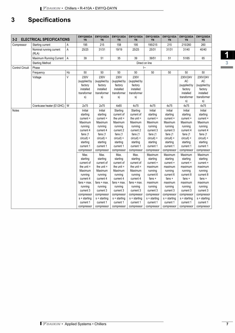
Compressor Starting current A 195 215 158 195 195/215 215 215/260 260Nominal running current (RLA)
A 25/25 31/31 19/19 25/25 25/31 31/31 31/40 40/40
Maximum Running Current A 39 51 35 39 39/51 51 51/65 65Starting Method Direct on line
Control Circuit Phase 1~Frequency Hz 50 50 50 50 50 50 50 50Voltage V 230V
(supplied by factory
installed transformer
s)
230V (supplied by
factory installed
transformers)
230V (supplied by
factory installed
transformers)
230V (supplied by
factory installed
transformers)
230V/24V AC
(supplied by factory
installed transformer
s)
230V/24V AC
(supplied by factory
installed transformer
s)Crankcase heater (E1/2HC) W 2x75 2x75 4x65 4x75 4x75 4x75 4x75 4x75
Notes Initial starting
current = Maximum running
current 4 fans (1
circuit) + starting
current 1 compressor
Initial starting
current = Maximum running
current 4 fans (1
circuit) + starting
current 1 compressor
Starting current of the unit = Maximum running
current 2 fans (1
circuit) + starting
current 1 compressor
Starting current of the unit = Maximum running
current 2 fans (1
circuit) + starting
current 1 compressor
Initial starting
current = Maximum running
current 3 fans (1
circuit) + starting
current 1 compressor
Initial starting
current = Maximum running
current 3 fans (1
circuit) + starting
current 1 compressor
Initial starting
current = Maximum running
current 4 fans (1
circuit) + starting
current 1 compressor
Initial starting
current = Maximum running
current 4 fans (1
circuit) + starting
current 1 compressor
Max. starting
current of the unit = Maximum running
current 4 fans + max.
running current 3
compressors + starting current 1
compressor
Max. starting
current of the unit = Maximum running
current 4 fans + max.
running current 3
compressors + starting current 1
compressor
Max. starting
current of the unit = Maximum running
current 4 fans + max.
running current 3
compressors + starting current 1
compressor
Max. starting
current of the unit = Maximum running
current 4 fans + max.
running current 3
compressors + starting current 1
compressor
Maximum starting
current = maximum running
current 6 fans +
maximum running
current 3 compressors + starting current 1
compressor
Maximum starting
current = maximum running
current 6 fans +
maximum running
current 3 compressors + starting current 1
compressor
Maximum starting
current = maximum running
current 8 fans +
maximum running
current 3 compressors + starting current 1
compressor
Maximum starting
current = maximum running
current 8 fans +
maximum running
current 3 compressors + starting current 1
compressor
3-2 ELECTRICAL SPECIFICATIONSEWYQ080DA
YNEWYQ100DA
YNEWYQ130DA
YNEWYQ150DA
YNEWYQ180DA
YNEWYQ210DA
YNEWYQ230DA
YNEWYQ250DA
YN
• Applied Systems • Chillers 7
• Chillers • R-410A • EWYQ-DAYN
13
8
3 Specifications
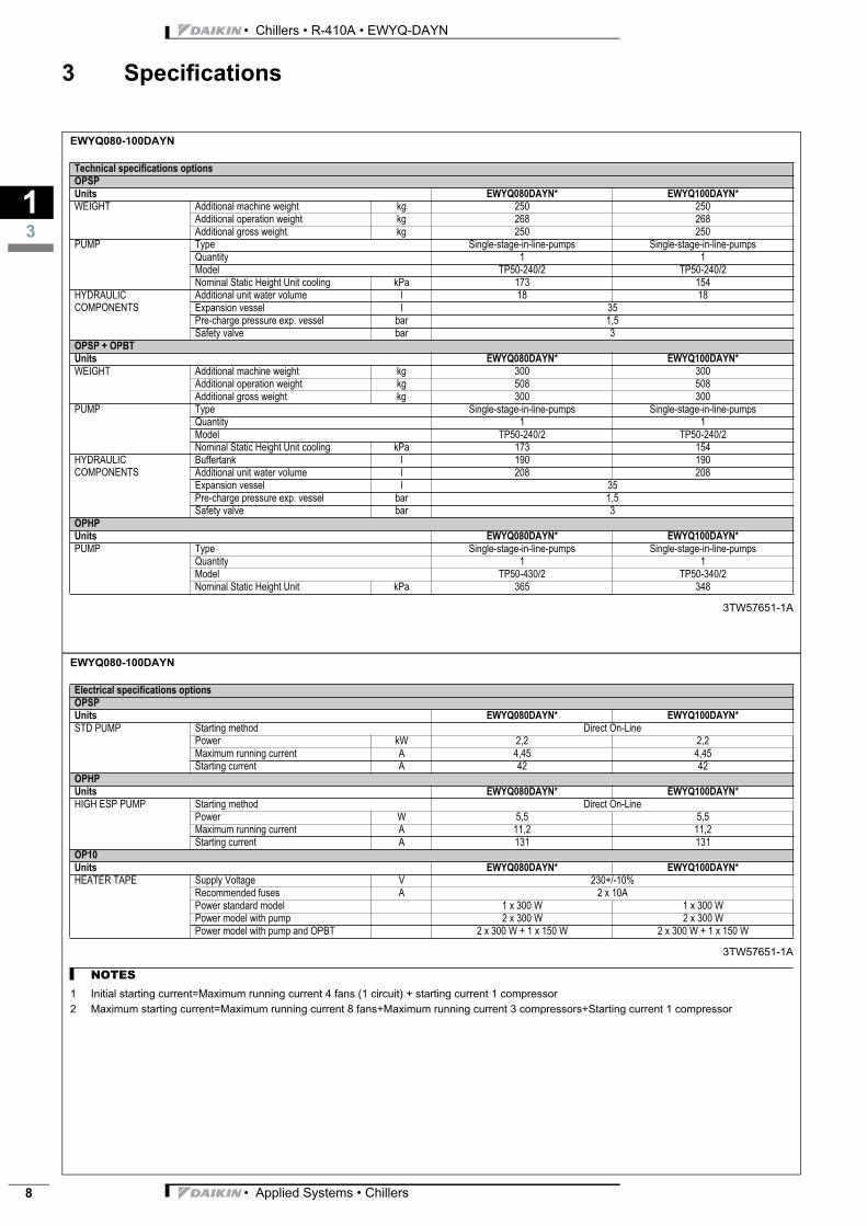
3-3 SPECIFICATIONS (OPTIONS)
EWYQ080-100DAYN
3TW57651-1A
Technical specifications optionsOPSPUnits EWYQ080DAYN* EWYQ100DAYN*WEIGHT Additional machine weight kg 250 250
Additional operation weight kg 268 268Additional gross weight kg 250 250
PUMP Type Single-stage-in-line-pumps Single-stage-in-line-pumpsQuantity 1 1Model TP50-240/2 TP50-240/2Nominal Static Height Unit cooling kPa 173 154
HYDRAULIC COMPONENTS
Additional unit water volume l 18 18Expansion vessel l 35Pre-charge pressure exp. vessel bar 1,5Safety valve bar 3
OPSP + OPBTUnits EWYQ080DAYN* EWYQ100DAYN*WEIGHT Additional machine weight kg 300 300
Additional operation weight kg 508 508Additional gross weight kg 300 300
PUMP Type Single-stage-in-line-pumps Single-stage-in-line-pumpsQuantity 1 1Model TP50-240/2 TP50-240/2Nominal Static Height Unit cooling kPa 173 154
HYDRAULIC COMPONENTS
Buffertank l 190 190Additional unit water volume l 208 208Expansion vessel l 35Pre-charge pressure exp. vessel bar 1,5Safety valve bar 3
OPHPUnits EWYQ080DAYN* EWYQ100DAYN*PUMP Type Single-stage-in-line-pumps Single-stage-in-line-pumps
Quantity 1 1Model TP50-430/2 TP50-340/2Nominal Static Height Unit kPa 365 348
EWYQ080-100DAYN
3TW57651-1A
NOTES
1 Initial starting current=Maximum running current 4 fans (1 circuit) + starting current 1 compressor
2 Maximum starting current=Maximum running current 8 fans+Maximum running current 3 compressors+Starting current 1 compressor
Electrical specifications optionsOPSPUnits EWYQ080DAYN* EWYQ100DAYN*STD PUMP Starting method Direct On-Line
Power kW 2,2 2,2Maximum running current A 4,45 4,45Starting current A 42 42
OPHPUnits EWYQ080DAYN* EWYQ100DAYN*HIGH ESP PUMP Starting method Direct On-Line
Power W 5,5 5,5Maximum running current A 11,2 11,2Starting current A 131 131
OP10Units EWYQ080DAYN* EWYQ100DAYN*HEATER TAPE Supply Voltage V 230+/-10%
Recommended fuses A 2 x 10APower standard model 1 x 300 W 1 x 300 WPower model with pump 2 x 300 W 2 x 300 WPower model with pump and OPBT 2 x 300 W + 1 x 150 W 2 x 300 W + 1 x 150 W
• Applied Systems • Chillers

3
13
• Chillers • R-410A • EWYQ-DAYN
3 Specifications
EWYQ130-150DAYN
3TW57671-1B
Technical specifications optionsOPSPUnits EWYQ130DAYN* EWYQ150DAYN*WEIGHT Additional machine weight kg 250 250
Additional operation weight kg 286 286Additional gross weight kg 250 250
PUMP Type Single-stage-in-line-pumps Single-stage-in-line-pumpsQuantity 1 1Model TP65-260/2 TP65-260/2Nominal Static Height Unit cooling kPa 141 141
HYDRAULIC COMPONENTS
Additional unit water volume l 36 36Expansion vessel l 35Pre-charge pressure exp. vessel bar 1,5Safety valve bar 3
OPSP + OPBTUnits EWYQ130DAYN* EWYQ150DAYN*WEIGHT Additional machine weight kg 300 300
Additional operation weight kg 526 526Additional gross weight kg 300 300
PUMP Type Single-stage-in-line-pumps Single-stage-in-line-pumpsQuantity 1 1Model TP65-260/2 TP65-260/2Nominal Static Height Unit cooling kPa 141 141
HYDRAULIC COMPONENTS
Buffertank l 190 190Additional unit water volume l 226 226Expansion vessel l 35Pre-charge pressure exp. vessel bar 1,5Safety valve bar 3
OPHPUnits EWYQ130DAYN* EWYQ150DAYN*PUMP Type Single-stage-in-line-pumps Single-stage-in-line-pumps
Quantity 1 1Model TP65-340/2 TP65-340/2Nominal Static Height Unit kPa 261 261
EWYQ130-150DAYN
3TW57671-1B
NOTES
1 Initial starting current=Maximum running current 4 fans (1 circuit) + starting current 1 compressor
2 Maximum starting current=Maximum running current 8 fans+Maximum running current 3 compressors+Starting current 1 compressor
Electrical specifications optionsOPSPUnits EWYQ130DAYN* EWYQ150DAYN*STD PUMP Starting method Direct On-Line
Power kW 3kW 3kWMaximum running current A 6,3 6,3Starting current A 58 58
OPHPUnits EWYQ130DAYN* EWYQ150DAYN*HIGH ESP PUMP Starting method Direct On-Line
Power W 5,5kW 5,5kWMaximum running current A 11,2 11,2Starting current A 131 131
OP10Units EWYQ130DAYN* EWYQ150DAYN*HEATER TAPE Supply Voltage V 230+/-10%
Recommended fuses A 2 x 10APower standard model 1 x 300 W 1 x 300 WPower model with pump 2 x 300 W 2 x 300 WPower model with pump and OPBT 2 x 300 W + 1 x 150 W 2 x 300 W + 1 x 150 W
• Applied Systems • Chillers 9
• Chillers • R-410A • EWYQ-DAYN
13
10
3 Specifications
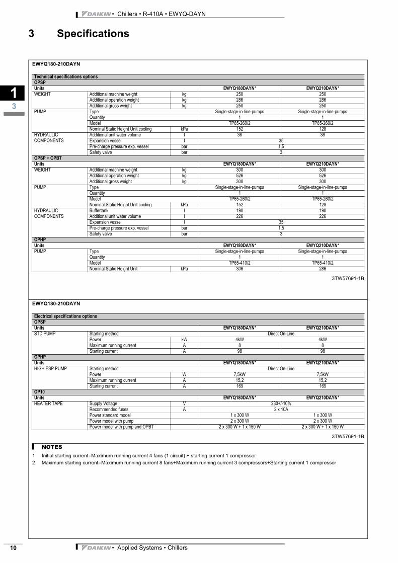
EWYQ180-210DAYN
3TW57691-1B
Technical specifications optionsOPSPUnits EWYQ180DAYN* EWYQ210DAYN*WEIGHT Additional machine weight kg 250 250
Additional operation weight kg 286 286Additional gross weight kg 250 250
PUMP Type Single-stage-in-line-pumps Single-stage-in-line-pumpsQuantity 1 1Model TP65-260/2 TP65-260/2Nominal Static Height Unit cooling kPa 152 128
HYDRAULIC COMPONENTS
Additional unit water volume l 36 36Expansion vessel l 35Pre-charge pressure exp. vessel bar 1,5Safety valve bar 3
OPSP + OPBTUnits EWYQ180DAYN* EWYQ210DAYN*WEIGHT Additional machine weight kg 300 300
Additional operation weight kg 526 526Additional gross weight kg 300 300
PUMP Type Single-stage-in-line-pumps Single-stage-in-line-pumpsQuantity 1 1Model TP65-260/2 TP65-260/2Nominal Static Height Unit cooling kPa 152 128
HYDRAULIC COMPONENTS
Buffertank l 190 190Additional unit water volume l 226 226Expansion vessel l 35Pre-charge pressure exp. vessel bar 1,5Safety valve bar 3
OPHPUnits EWYQ180DAYN* EWYQ210DAYN*PUMP Type Single-stage-in-line-pumps Single-stage-in-line-pumps
Quantity 1 1Model TP65-410/2 TP65-410/2Nominal Static Height Unit kPa 306 286
EWYQ180-210DAYN
3TW57691-1B
NOTES
1 Initial starting current=Maximum running current 4 fans (1 circuit) + starting current 1 compressor
2 Maximum starting current=Maximum running current 8 fans+Maximum running current 3 compressors+Starting current 1 compressor
Electrical specifications optionsOPSPUnits EWYQ180DAYN* EWYQ210DAYN*STD PUMP Starting method Direct On-Line
Power kW 4kW 4kWMaximum running current A 8 8Starting current A 98 98
OPHPUnits EWYQ180DAYN* EWYQ210DAYN*HIGH ESP PUMP Starting method Direct On-Line
Power W 7,5kW 7,5kWMaximum running current A 15,2 15,2Starting current A 169 169
OP10Units EWYQ180DAYN* EWYQ210DAYN*HEATER TAPE Supply Voltage V 230+/-10%
Recommended fuses A 2 x 10APower standard model 1 x 300 W 1 x 300 WPower model with pump 2 x 300 W 2 x 300 WPower model with pump and OPBT 2 x 300 W + 1 x 150 W 2 x 300 W + 1 x 150 W
• Applied Systems • Chillers
3
13
• Chillers • R-410A • EWYQ-DAYN
3 Specifications
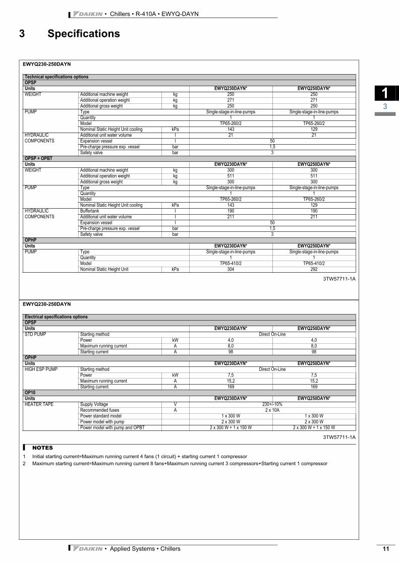
EWYQ230-250DAYN
3TW57711-1A
Technical specifications optionsOPSPUnits EWYQ230DAYN* EWYQ250DAYN*WEIGHT Additional machine weight kg 250 250
Additional operation weight kg 271 271Additional gross weight kg 250 250
PUMP Type Single-stage-in-line-pumps Single-stage-in-line-pumpsQuantity 1 1Model TP65-260/2 TP65-260/2Nominal Static Height Unit cooling kPa 143 129
HYDRAULIC COMPONENTS
Additional unit water volume l 21 21Expansion vessel l 50Pre-charge pressure exp. vessel bar 1,5Safety valve bar 3
OPSP + OPBTUnits EWYQ230DAYN* EWYQ250DAYN*WEIGHT Additional machine weight kg 300 300
Additional operation weight kg 511 511Additional gross weight kg 300 300
PUMP Type Single-stage-in-line-pumps Single-stage-in-line-pumpsQuantity 1 1Model TP65-260/2 TP65-260/2Nominal Static Height Unit cooling kPa 143 129
HYDRAULIC COMPONENTS
Buffertank l 190 190Additional unit water volume l 211 211Expansion vessel l 50Pre-charge pressure exp. vessel bar 1,5Safety valve bar 3
OPHPUnits EWYQ230DAYN* EWYQ250DAYN*PUMP Type Single-stage-in-line-pumps Single-stage-in-line-pumps
Quantity 1 1Model TP65-410/2 TP65-410/2Nominal Static Height Unit kPa 304 292
EWYQ230-250DAYN
3TW57711-1A
NOTES
1 Initial starting current=Maximum running current 4 fans (1 circuit) + starting current 1 compressor
2 Maximum starting current=Maximum running current 8 fans+Maximum running current 3 compressors+Starting current 1 compressor
Electrical specifications optionsOPSPUnits EWYQ230DAYN* EWYQ250DAYN*STD PUMP Starting method Direct On-Line
Power kW 4,0 4,0Maximum running current A 8,0 8,0Starting current A 98 98
OPHPUnits EWYQ230DAYN* EWYQ250DAYN*HIGH ESP PUMP Starting method Direct On-Line
Power kW 7,5 7,5Maximum running current A 15,2 15,2Starting current A 169 169
OP10Units EWYQ230DAYN* EWYQ250DAYN*HEATER TAPE Supply Voltage V 230+/-10%
Recommended fuses A 2 x 10APower standard model 1 x 300 W 1 x 300 WPower model with pump 2 x 300 W 2 x 300 WPower model with pump and OPBT 2 x 300 W + 1 x 150 W 2 x 300 W + 1 x 150 W
• Applied Systems • Chillers 11

• Chillers • R-410A • EWYQ-DAYN
14
12
4 Options
EWYQ-DAYN(N-P-B)
Optional equipment for EWYQ-DAYNN
Capacity: 080-250 kW
EWYQ080DAYNN EWYQ150DAYNN EWYQ230DAYNN
EWYQ100DAYNN EWYQ180DAYNN EWYQ250DAYNN
EWYQ130DAYNN EWYQ210DAYNN
3TW57659-8
NOTES
° Available
- Not available
(S) Option required for Swedish national law SNFS 1992:16
Option number Option discription Unit size Availability080 100 130 150 180 210 230 250
Standard unit ° ° ° ° ° ° ° °OPSC Single pump contactor ° ° ° ° ° ° ° ° fact. mount.OPTC Twin pump contactor ° ° ° ° ° ° ° ° fact. mount.OPSP Single pump ° ° ° ° ° ° ° ° fact. mount.OPTP Twin pump (1 pump house, dual motor) ° ° ° ° ° ° ° ° fact. mount.OPHP High ESP pump (single pump only) ° ° ° ° ° ° ° ° fact. mount.OPBT Buffer tank ° ° ° ° ° ° ° ° fact. mount.OPIF Inverter fans (For low ambient -15°C) ° ° ° ° ° ° ° ° fact. mount.OPZL Glycol 0°C / -10°C ° ° ° ° ° ° ° ° fact. mount.OP03 Dual pressure relief valve ° ° ° ° ° ° ° ° fact. mount.OP10 Evaporator heater tape ° ° ° ° ° ° ° ° fact. mount.OP12 Option valves (discharge-, liquid line- and suction stop valve) °(S) °(S) °(S) °(S) °(S) °(S) °(S) °(S) fact. mount.OP57 A-meter / V-meter ° ° ° ° ° ° ° ° fact. mount.OPLN Low noise = OPIF + Compressor housing ° ° ° ° ° ° ° ° fact. mount.OPCG Condenser protection grills ° ° ° ° ° ° ° ° fact. mount.
Available kitsEKLONPG Gateway for LON ° ° ° ° ° ° ° ° KitEKBNPG Gateway for BACNET ° ° ° ° ° ° ° ° KitEKACPG Adress card ° ° ° ° ° ° ° ° KitEKRUPG Remote user interface ° ° ° ° ° ° ° ° Kit
• Applied Systems • Chillers
3
15
• Chillers • R-410A • EWYQ-DAYN
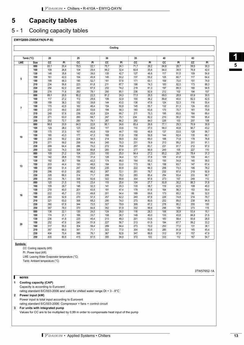
5 Capacity tables
5 - 1 Cooling capacity tablesEWYQ080-250DAYN(N-P-B)
3TW57652-1A
NOTES
1 Cooling capacity (CAP)
Capacity is according to Eurovent
rating standard 6/C/003-2006 and valid for chilled water range Dt = 3 - 8°C
2 Power input (kW)
Power input is total input according to Eurovent
rating standard 6/C/003-2006: Compressor + fans + control circuit
3 For units with integrated pump
Values for CC are to be multiplied by 0,99 in order to compensate heat input of the pump
Cooling
Tamb (°C) 20 25 30 35 40 43
LWE Size CC PI CC PI CC PI CC PI CC PI CC PI
5
080 83,1 20,4 79,5 22,1 75,7 24,1 71,7 26,2 64,8 28,7 59,5 30,3
100 109 26,8 104 29,4 99,2 32,4 93,6 35,8 84,0 39,5 76,9 42,0
130 148 35,6 142 39,0 135 42,7 127 46,8 117 51,5 109 54,6
150 161 42,0 154 45,9 145 50,2 137 55,2 125 60,7 117 64,4
180 199 48,3 190 52,7 181 57,6 171 63,1 159 70,0 151 74,9
210 234 56,6 223 61,8 211 67,7 198 74,3 183 82,5 173 88,3
230 254 62,2 243 67,9 232 74,2 219 81,3 197 89,3 180 94,5
250 274 71,8 262 78,1 250 85,1 236 92,9 212 102 194 107
7
080 89,1 20,5 85,2 22,3 81,2 24,3 77,0 26,5 69,5 28,9 63,9 30,5
100 117 27,2 112 29,9 106 32,9 100 36,2 89,8 40,0 82,3 42,5
130 159 36,3 152 39,8 144 43,5 136 47,6 124 52,3 116 55,4
150 170 42,5 162 46,4 154 50,8 145 55,7 132 61,3 124 65,0
180 213 49,0 203 53,6 194 58,3 183 63,8 170 70,7 161 75,6
210 248 57,6 236 62,8 224 68,7 211 75,3 195 83,5 184 89,4
230 271 63,0 260 68,7 247 75,1 234 82,2 210 90,2 193 95,4
250 292 72,7 280 79,1 267 86,2 252 94,0 226 103 207 108
10
080 98,6 20,9 94,5 22,6 90,1 24,6 85,4 26,8 77,1 29,3 70,9 30,9
100 129 28,0 123 30,6 117 33,6 110 37,0 99,0 40,8 90,7 43,2
130 175 37,5 167 40,9 159 44,7 150 48,9 137 53,5 128 56,7
150 185 43,3 177 47,3 168 51,8 158 56,8 144 62,4 135 66,1
180 235 50,2 224 54,5 214 59,5 202 65,0 188 71,9 178 76,8
210 271 59,2 258 64,4 245 70,3 231 76,9 213 85,2 201 91,1
230 299 64,4 286 70,2 272 76,6 257 83,7 231 91,7 212 97,0
250 322 74,3 308 80,8 293 87,9 277 95,9 249 105 227 110
13
080 109 21,2 104 23,0 100 25,0 94,4 27,2 85,2 29,7 78,4 31,3
100 142 28,8 135 31,4 128 34,4 121 37,8 109 41,6 100 44,1
130 192 38,7 184 42,2 174 46,0 164 50,2 150 54,9 140 58,0
150 203 44,4 193 48,5 184 53,0 173 58,1 158 63,7 147 67,4
180 258 51,4 247 55,8 235 60,8 222 66,3 206 73,3 195 78,2
210 296 61,0 282 66,2 267 72,1 251 78,7 232 87,0 219 92,9
230 328 66,0 314 71,7 299 78,2 283 85,4 254 93,4 233 98,7
250 353 76,1 338 82,6 322 89,8 304 97,8 273 107 249 112
16
080 120 21,5 115 23,4 110 25,4 104 27,7 93,8 30,2 86,3 31,8
100 155 29,7 148 32,3 141 35,3 133 38,7 119 42,5 109 45,0
130 210 40,0 201 43,5 191 47,4 179 51,6 164 56,3 153 59,4
150 222 45,7 212 49,8 201 54,4 189 59,6 173 65,2 88 32,0
180 283 52,9 270 57,3 257 62,2 243 67,8 226 74,8 214 79,7
210 321 63,0 306 68,2 290 74,0 273 80,6 252 89,0 238 94,9
230 360 67,8 344 73,5 327 79,9 309 87,2 278 95,2 255 100
250 387 78,0 370 84,6 352 91,9 332 99,9 298 109 273 115
20
080 136 22,1 130 24,0 124 26,0 118 28,3 106 30,9 53,4 15,1
100 174 31,1 166 33,7 158 36,7 149 40,0 133 43,8 66,8 21,5
130 236 41,8 225 45,4 213 49,3 201 53,6 183 58,4 93,6 28,5
150 252 47,6 240 51,9 227 56,7 213 61,9 194 67,7 99,2 33,2
180 317 55,0 304 59,4 289 64,4 273 70,0 253 77,0 131 38,1
210 357 66,0 341 71,1 323 77,0 304 83,6 280 91,9 145 45,4
230 404 70,4 386 76,1 367 82,6 347 89,8 312 97,9 157 47,9
250 435 80,8 415 87,5 395 94,9 372 103 333 112 167 54,7
Symbols:
CC: Cooling capacity (kW)
PI : Power input (kW)
LWE: Leaving Water Evaporator temperature (°C)
Tamb: Ambient temperature (°C)
• Applied Systems • Chillers 13

• Chillers • R-410A • EWYQ-DAYN
15
14
5 Capacity tables
5 - 2 Heating capacity tablesEWYQ080-250DAYN(N-B-P)
Note 1: HC tabulated does not include capacity drop during frosting period and defrost.The integrated Heating Capacity takes into consideration the capacity drop during frosting period and defrosting operation.
(HC integrated)=(HC)*(Integrated correction factor during frosting period)
- Integrated heating capacity means the heating capacity during one cycle(between defrosting period and defrosting period),which is integrated and converted to heatingcapacity per hour.
- Integrated correction factor:
Note 2: In case the surface of the heat exchanger is covered with snow, heating capacity drops temporarily although it differs with outdoor temperature (°CDB), relative humidity (RH) and frosting volume
NOTES
1 Heating capacity (CAP)Capacity is according to Eurovent rating standard 6/C/003-2006 and valid for heated water range Dt = 3 - 8°C
2 Power input (kW)Power input is total input according to Eurovent rating standard 6/C/003-2006: Compressor + fans + control circuit
3TW57652-1A
HEATING
Tamb (°CDB) -10 -7 -4 0 4 7 10 15 21
LWE Size HC PI HC PI HC PI HC PI HC PI HC PI HC PI HC PI HC PI
25
080 58,4 19,8 64,5 20,0 70,5 20,1 78,0 20,3 86,0 20,6 92,4 20,9 99,0 21,1 110 21,6 125 22,2
100 74,1 23,9 82,3 24,2 90,3 24,4 100 24,8 111 25,2 119 25,5 127 25,9 142 26,5 159 27,3
130 97 31,7 108 32,2 118 32,7 131 33,4 145 34,1 156 34,7 167 35,3 186 36,3 210 37,4
150 107 40,0 118 40,0 129 40,1 143 40,2 157 40,5 168 40,7 179 40,9 199 41,4 223 41,9
180 129 44,1 144 44,5 158 44,9 176 45,5 194 46,2 208 46,7 222 47,3 246 48,3 273 49,5
210 141 50,7 158 51,0 174 51,3 193 51,6 214 52,0 229 52,3 244 52,6 270 53,3 299 54,1
230 168 55,8 187 56,4 205 57,0 227 57,8 250 58,7 268 59,3 587 60,0 319 61,1 358 62,6
250 186 63,2 206 64,1 226 64,8 250 65,9 275 66,9 295 67,7 315 68,5 350 69,9 391 71,5
30
080 57,4 21,8 63,3 21,9 69,8 22,0 77,2 22,2 85,0 22,5 91,2 22,8 97,6 23,0 109 23,5 123 24,5
100 73,2 26,4 81,2 26,7 89,8 27,0 99,5 27,4 110 27,8 118 28,2 126 28,5 140 29,1 157 30,0
130 96 34,8 106 35,3 117 35,8 130 36,5 144 37,2 154 37,8 165 38,4 184 39,4 207 40,6
150 106 44,1 117 44,0 129 44,0 142 44,1 156 44,3 167 44,5 178 44,7 197 45,1 221 45,7
180 127 48,5 142 48,9 157 49,3 174 49,9 192 50,6 206 51,2 220 51,7 243 52,8 269 54,0
210 140 55,8 157 56,2 174 56,5 193 56,8 213 57,2 228 57,5 243 57,8 268 58,3 296 59,1
240 166 61,2 184 61,9 204 62,6 226 63,5 248 64,4 266 65,1 284 65,8 315 67,0 353 68,5
250 184 69,1 204 70,0 225 70,9 249 72,0 273 73,2 293 74,0 312 74,9 346 76,3 386 78,1
35
080 56,6 24,0 62,4 24,1 68,7 24,2 76,5 24,4 84,1 24,7 90,0 24,9 96,3 25,2 107 25,7 121 26,4
100 72,5 29,1 80,4 29,5 88,7 29,8 99,0 30,3 109 30,7 116 31,1 124 31,5 138 32,1 155 33,0
130 95 38,4 105 38,8 116 39,3 129 39,9 142 40,7 153 41,2 163 41,8 181 42,9 204 44,1
150 105 48,6 116 48,5 127 48,4 142 48,4 155 48,5 166 48,7 177 48,9 196 49,3 219 49,8
180 126 53,3 140 53,7 155 54,2 173 54,9 190 55,6 204 56,1 217 56,7 239 57,8 265 59,1
210 140 61,5 156 61,9 173 62,2 193 62,6 212 63,0 227 63,2 241 63,5 266 64,0 294 64,7
240 165 67,3 182 68,1 201 68,8 224 69,8 246 70,8 263 71,5 281 72,3 311 73,6 348 75,2
250 182 75,7 202 76,7 222 77,6 247 78,9 271 80,1 290 81,1 309 82,0 341 83,6 381 85,5
40
080 56,2 26,5 61,7 26,5 67,7 26,6 75,9 26,8 83,2 27,1 88,9 27,3 88,9 27,6 105 28,1 118 28,8
100 72,1 32,2 79,7 32,6 87,7 33,0 98,5 33,5 108 34,0 115 34,4 123 34,8 136 35,5 152 36,3
130 94 42,5 104 42,8 115 43,2 129 43,9 141 44,6 151 45,1 161 45,7 178 46,8 200 48,1
150 105 53,7 116 53,5 127 53,3 142 53,3 155 53,3 165 53,4 176 53,6 194 54,0 217 54,5
180 125 58,8 139 59,2 153 59,7 172 60,4 189 61,1 201 61,7 214 62,3 236 63,4 261 64,8
210 140 67,7 156 68,2 172 68,6 193 69,1 212 69,5 226 69,7 240 70,0 264 70,5 291 71,1
240 164 74,1 181 75,0 199 75,8 223 76,9 244 78,0 261 78,8 278 79,6 307 81,0 342 82,7
250 181 83,2 200 84,2 220 85,3 246 86,7 269 88,0 287 89,0 305 90,0 337 91,7 375 93,8
45
080 66,9 29,4 74,7 29,5 82,3 29,8 87,7 30,0 93,4 30,3 103 306 116 30,8
100 86,8 36,6 97,1 37,2 107 37,7 114 38,1 121 38,5 134 39,3 149 40,2
130 113 47,9 127 48,4 140 49,1 149 49,6 159 50,2 175 51,2 196 52,6
150 127 58,9 141 58,7 155 58,7 165 58,8 175 58,9 193 59,3 215 59,8
180 151 65,9 169 66,6 187 67,4 199 68,0 211 68,6 232 69,8 256 71,2
210 171 75,8 192 76,3 212 76,8 225 77,0 239 77,3 262 77,8 289 78,3
240 197 83,7 220 84,9 242 86,1 258 86,9 274 87,8 302 89,3 336 91,1
250 217 93,9 242 95,4 267 96,9 284 97,9 301 99,0 331 101 368 103
50
080 73,4 32,6 81,4 32,9 86,4 33,1 91,7 33,4 101 33,9 113 34,7
100 95,7 41,3 106 41,9 113 42,3 210 42,7 132 43,5 146 44,4
130 125 53,7 138 54,3 147 54,8 156 55,3 172 56,3 191 57,7
150 140 64,9 155 64,8 165 64,9 175 65,0 192 65,3 213 65,8
180 167 73,7 185 74,4 196 75,1 208 75,7 228 76,9 251 78,3
210 191 84,5 212 85,0 225 85,3 238 85,6 260 8,0 286 86,5
240 216 93,9 240 95,2 255 96,1 270 97,0 296 98,6 329 100
250 238 105 264 107 280 108 296 109 325 111 359 113
Tamb [°C] RH 85% -10 -7 -4 0 4 7
Correction factor 0,96 0,95 0,92 0,87 0,90 1,00
- Intergrated heating capacity graph
Defrost Defrost
Time
HC
One cycle
Heating operation
Symbols:
HC : Heating Capacity (kW)
PI : Power Input (kW)
LWC : Leaving Water Condensor temperature (°C)
Tamb : Ambient temperature dry bulb (°C)
• Applied Systems • Chillers
3
16
• Chillers • R-410A • EWYQ-DAYN
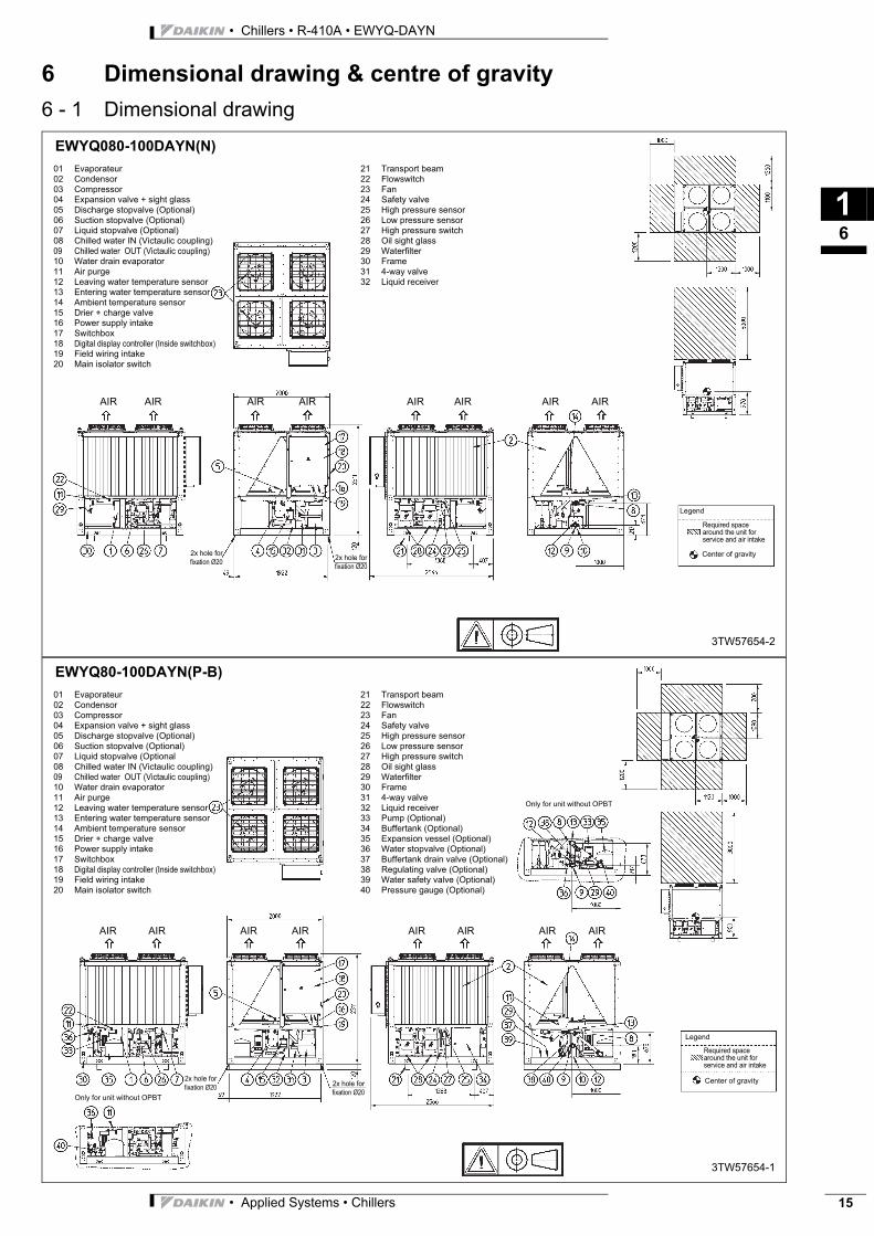
6 Dimensional drawing & centre of gravity
6 - 1 Dimensional drawingEWYQ080-100DAYN(N)
01 Evaporateur
02 Condensor
03 Compressor
04 Expansion valve + sight glass
05 Discharge stopvalve (Optional)
06 Suction stopvalve (Optional)
07 Liquid stopvalve (Optional)
08 Chilled water IN (Victaulic coupling)
09 Chilled water OUT (Victaulic coupling)
10 Water drain evaporator
11 Air purge
12 Leaving water temperature sensor
13 Entering water temperature sensor
14 Ambient temperature sensor
15 Drier + charge valve
16 Power supply intake
17 Switchbox
18 Digital display controller (Inside switchbox)
19 Field wiring intake
20 Main isolator switch
21 Transport beam
22 Flowswitch
23 Fan
24 Safety valve
25 High pressure sensor
26 Low pressure sensor
27 High pressure switch
28 Oil sight glass
29 Waterfilter
30 Frame
31 4-way valve
32 Liquid receiver
2x hole for
fixation Ø202x hole for
fixation Ø20
Required space
around the unit for
service and air intake
Legend
Center of gravity
3TW57654-2
AIRAIRAIR AIRAIR AIRAIRAIR
EWYQ80-100DAYN(P-B)
01 Evaporateur
02 Condensor
03 Compressor
04 Expansion valve + sight glass
05 Discharge stopvalve (Optional)
06 Suction stopvalve (Optional)
07 Liquid stopvalve (Optional
08 Chilled water IN (Victaulic coupling)
09 Chilled water OUT (Victaulic coupling)
10 Water drain evaporator
11 Air purge
12 Leaving water temperature sensor
13 Entering water temperature sensor
14 Ambient temperature sensor
15 Drier + charge valve
16 Power supply intake
17 Switchbox
18 Digital display controller (Inside switchbox)
19 Field wiring intake
20 Main isolator switch
21 Transport beam
22 Flowswitch
23 Fan
24 Safety valve
25 High pressure sensor
26 Low pressure sensor
27 High pressure switch
28 Oil sight glass
29 Waterfilter
30 Frame
31 4-way valve
32 Liquid receiver
33 Pump (Optional)
34 Buffertank (Optional)
35 Expansion vessel (Optional)
36 Water stopvalve (Optional)
37 Buffertank drain valve (Optional)
38 Regulating valve (Optional)
39 Water safety valve (Optional)
40 Pressure gauge (Optional)
2x hole for
fixation Ø202x hole for
fixation Ø20
Required space
around the unit for
service and air intake
Legend
Center of gravity
3TW57654-1
AIRAIRAIR AIRAIR AIRAIRAIR
Only for unit without OPBT
Only for unit without OPBT
• Applied Systems • Chillers 15
• Chillers • R-410A • EWYQ-DAYN
16
16
6 Dimensional drawing & centre of gravity
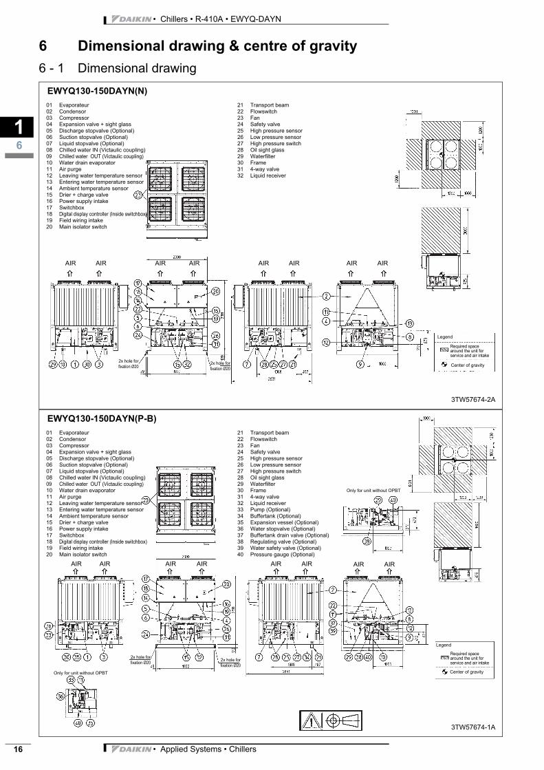
6 - 1 Dimensional drawingEWYQ130-150DAYN(N)
01 Evaporateur
02 Condensor
03 Compressor
04 Expansion valve + sight glass
05 Discharge stopvalve (Optional)
06 Suction stopvalve (Optional)
07 Liquid stopvalve (Optional)
08 Chilled water IN (Victaulic coupling)
09 Chilled water OUT (Victaulic coupling)
10 Water drain evaporator
11 Air purge
12 Leaving water temperature sensor
13 Entering water temperature sensor
14 Ambient temperature sensor
15 Drier + charge valve
16 Power supply intake
17 Switchbox
18 Digital display controller (Inside switchbox)
19 Field wiring intake
20 Main isolator switch
21 Transport beam
22 Flowswitch
23 Fan
24 Safety valve
25 High pressure sensor
26 Low pressure sensor
27 High pressure switch
28 Oil sight glass
29 Waterfilter
30 Frame
31 4-way valve
32 Liquid receiver
2x hole for
fixation Ø202x hole for
fixation Ø20
Required space
around the unit for
service and air intake
Legend
Center of gravity
3TW57674-2A
AIRAIRAIR AIRAIR AIRAIRAIR
EWYQ130-150DAYN(P-B)
01 Evaporateur
02 Condensor
03 Compressor
04 Expansion valve + sight glass
05 Discharge stopvalve (Optional)
06 Suction stopvalve (Optional)
07 Liquid stopvalve (Optional)
08 Chilled water IN (Victaulic coupling)
09 Chilled water OUT (Victaulic coupling)
10 Water drain evaporator
11 Air purge
12 Leaving water temperature sensor
13 Entering water temperature sensor
14 Ambient temperature sensor
15 Drier + charge valve
16 Power supply intake
17 Switchbox
18 Digital display controller (Inside switchbox)
19 Field wiring intake
20 Main isolator switch
21 Transport beam
22 Flowswitch
23 Fan
24 Safety valve
25 High pressure sensor
26 Low pressure sensor
27 High pressure switch
28 Oil sight glass
29 Waterfilter
30 Frame
31 4-way valve
32 Liquid receiver
33 Pump (Optional)
34 Buffertank (Optional)
35 Expansion vessel (Optional)
36 Water stopvalve (Optional)
37 Buffertank drain valve (Optional)
38 Regulating valve (Optional)
39 Water safety valve (Optional)
40 Pressure gauge (Optional)
2x hole for
fixation Ø202x hole for
fixation Ø20
Required space
around the unit for
service and air intake
Legend
Center of gravity
3TW57674-1A
AIR
Only for unit without OPBT
AIRAIR AIRAIRAIRAIRAIR
Only for unit without OPBT
• Applied Systems • Chillers
3
16
• Chillers • R-410A • EWYQ-DAYN
6 Dimensional drawing & centre of gravity
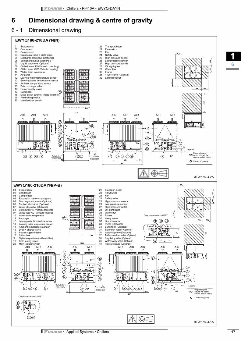
6 - 1 Dimensional drawingEWYQ180-210DAYN(N)
01 Evaporateur
02 Condensor
03 Compressor
04 Expansion valve + sight glass
05 Discharge stopvalve (Optional)
06 Suction stopvalve (Optional)
07 Liquid stopvalve (Optional)
08 Chilled water IN (Victaulic coupling)
09 Chilled water OUT (Victaulic coupling)
10 Water drain evaporator
11 Air purge
12 Leaving water temperature sensor
13 Entering water temperature sensor
14 Ambient temperature sensor
15 Drier + charge valve
16 Power supply intake
17 Switchbox
18 Digital display controller (Inside switchbox)
19 Field wiring intake
20 Main isolator switch
21 Transport beam
22 Flowswitch
23 Fan
24 Safety valve
25 High pressure sensor
26 Low pressure sensor
27 High pressure switch
28 Oil sight glass
29 Waterfilter
30 Frame
31 4-way valve (Optional)
32 Liquid receiver
AIR AIR
2x hole for
fixation Ø20
2x hole for
fixation Ø20
Required space
around the unit for
service and air intake
Legend
Center of gravity
3TW57694-2A
AIR AIR AIR AIR AIR AIR
EWYQ180-210DAYN(P-B)01 Evaporateur
02 Condensor
03 Compressor
04 Expansion valve + sight glass
05 Discharge stopvalve (Optional)
06 Suction stopvalve (Optional)
07 Liquid stopvalve (Optional)
08 Chilled water IN (Victaulic coupling)
09 Chilled water OUT (Victaulic coupling)
10 Water drain evaporator
11 Air purge
12 Leaving water temperature sensor
13 Entering water temperature sensor
14 Ambient temperature sensor
15 Drier + charge valve
16 Power supply intake
17 Switchbox
18 Digital display controller (Inside switchbox)
19 Field wiring intake
20 Main isolator switch
21 Transport beam
22 Flowswitch
23 Fan
24 Safety valve
25 High pressure sensor
26 Low pressure sensor
27 High pressure switch
28 Oil sight glass
29 Waterfilter
30 Frame
31 4-way valve
32 Liquid receiver
33 Pump (Optional)
34 Buffertank (Optional)
35 Expansion vessel (Optional)
36 Water stopvalve (Optional)
37 Buffertank drain valve (Optional)
38 Regulating valve (Optional)
39 Water safety valve (Optional)
40 Pressure gauge (Optional)
2x hole for
fixation Ø20
2x hole for
fixation Ø20
Required space
around the unit for
service and air intake
Legend
Center of gravity
3TW57694-1A
AIR
Only for unit without OPBT
AIR AIR AIR AIR AIR AIR AIR AIR AIR
Only for unit without OPBT
• Applied Systems • Chillers 17

• Chillers • R-410A • EWYQ-DAYN
16
18
6 Dimensional drawing & centre of gravity
6 - 1 Dimensional drawingEWYQ230-250DAYN(N)
01 Evaporateur
02 Condensor
03 Compressor
04 Expansion valve + sight glass
05 Discharge stopvalve (Optional)
06 Suction stopvalve (Optional)
07 Liquid stopvalve (Optional)
08 Chilled water IN (Victaulic coupling)
09 Chilled water OUT (Victaulic coupling)
10 Water drain evaporator
11 Air purge
12 Leaving water temperature sensor
13 Entering water temperature sensor
14 Ambient sensor
15 Drier + charge valve
16 Power supply intake
17 Switchbox
18 Digital display controller (Inside switchbox)
19 Field wiring intake
20 Main isolator switch
21 Transport beam
22 Flowswitch
23 Fan
24 Safety valve
25 High pressure sensor
26 Low pressure sensor
27 High pressure switch
28 Oil sight glass
29 Waterfilter
30 Frame
31 4-way valve
32 Liquid receiver
AIR AIR AIR AIR AIR AIR
Required space
around the unit for
service and air intake
Legend
Center of gravity
3TW57714-2
AIR AIR AIR AIR AIR AIR
EWYQ230-250DAYN(P-B)
01 Evaporateur
02 Condensor
03 Compressor
04 Expansion valve + sight glass
05 Discharge stopvalve (Optional)
06 Suction stopvalve (Optional)
07 Liquid stopvalve (Optional)
08 Chilled water IN (Victaulic coupling)
09 Chilled water OUT (Victaulic coupling)
10 Water drain evaporator
11 Air purge
12 Leaving water temperature sensor
13 Entering water temperature sensor
14 Ambient temperature sensor
15 Drier + charge valve
16 Power supply intake
17 Switchbox
18 Digital display controller (Inside switchbox)
19 Field wiring intake
20 Main isolator switch
21 Transport beam
22 Flowswitch
23 Fan
24 Safety valve
25 High pressure sensor
26 Low pressure sensor
27 High pressure switch
28 Oil sight glass
29 Waterfilter
30 Frame
31 4-way valve
32 Liquid receiver
33 Pump (Optional)
34 Buffertank (Optional)
35 Expansion vessel (Optional)
36 Water stopvalve (Optional)
37 Buffertank drain valve (Optional)
38 Regulating valve (Optional)
39 Water safety valve (Optional)
40 Pressure gauge (Optional)
2x hole for
fixation Ø20
2x hole for
fixation Ø20
Required space
around the unit for
service and air intake
Legend
Center of gravity
3TW57714-1
Only for unit without OPBT
AIR AIR AIR AIR AIR AIR AIR AIR AIR AIR AIR AIR
Only for unit without OPBT
• Applied Systems • Chillers
3
17
• Chillers • R-410A • EWYQ-DAYN
7 Piping diagram
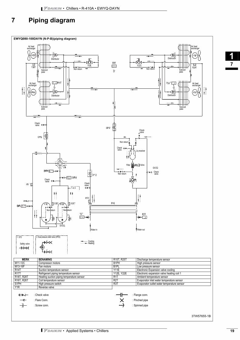
EWYQ080-100DAYN (N-P-B)(piping diagram)
3TW57655-1B
MERK BENAMING R15T, R25T Discharge temperature sensorM11-12C Compressor motors B1PH High pressure sensorM13-16F Fan motors B1PL Low pressure sensorR14T Suction temperature sensor Y11E Electronic Expansion valve coolingR17T Refrigerant piping temperature sensor Y12E, Y22E Electronic expansion valve heating coil 1R18T, R28T Heating suction piping temperature sensor R1T Ambient temperature sensorR16T, R26T Coil temperature sensor R2T Evaporator inlet water temperature sensorS1PH High pressure switch R3T Evaporator outlet water temperature sensorY1R Reverse valve
: Check valve : Flange conn.
: Flare Conn. : Pinched pipe
: Screw conn. : Spinned pipe
Air heat exchanger
Distributor
Distributor
Subcoolpass
Check valve
Filter
Non return
Non return
Liq receiver
Water out
Check valve
Distributor
Distributor
Check valve
Air heat exchanger
Subcool pass
Non return
Oil EQ
Safety valve
2. Dual pressure relief valve (OP03)
Air heat exchanger
Subcoolpass
Check valve
Air heat exchanger
Check valve
Check valve
Non returnNon return
1. STD
Non return
Valve
Water in
CoolingHeating
Subcool pass
Oil EQ.
1 or 2
• Applied Systems • Chillers 19

• Chillers • R-410A • EWYQ-DAYN
17
20
7 Piping diagram
EWYQ130-210DAYN (N-P-B)(piping diagram)
2TW57675-1A
Merk Benaming R36T Coil temperature sensor circuit 2M11-12C Compressor motors circuit 1 R37T Refrigerant piping temperature sensor circuit 2M13-15F Fan motors circuit 1 R38T Heating suction temp sensor circuit 2R14T Suction temperature sensor circuit 1 S2PH High pressure switch circuit 2R16T Coil temperature sensor circuit 1 Y2R Reverse valve circuit 2R17T Regrigerant piping temperature sensor circuit 1 R35T, R45T Discharge temperature sensor circuit 2R18T Heating suction temp sensor circuit 1 B2PH High pressure sensor circuit 2S1PH High pressure sensor circuit 1 B2PL Low pressure sensor circuit 2B1PL Low pressure sensor circuit 1 Y21E Electronic Expansion valve cooling circuit 2Y11E Electronic Expansion valve cooling crcuit 1 Y22E Electronic expansion valve heating circuit 2Y12E Electronic expansion valve heating circuit 1 R1T Ambient temperature sensorM21-22C Compressor motors circuit 2 R2T Evaporator inlet water temperature sensorM23-25F Fan motors crcuit 2 R3T Evaporator outlet water temperature sensorR34T Suction temperature sensor circuit 2
: Check valve : Flange conn.
: Flare Conn. : Pinched pipe
: Screw conn. : Spinned pipe
Air heat exchanger
Distributor
Distributor
Subcoolpass
Check valve
Water out
Distributor
Distributor
Check valve
Air heat exchanger
Subcool pass
Non return
Safety valve
2. Dual pressure relief valve (OP03)
Air heat exchanger
Subcoolpass
Check valve
Non returnNon return
1. STD
Non return
Water in
CoolingHeating
Subcool pass
Only EWYQ180-210DAYN*
Nonreturn
Nonreturn
Check valve
Check valve
Check valve
Check valve
Non returnNon return
Subcool pass
Only EWYQ180-210DAYN*
Check valve
1 or 2
Check valve
Check valve
Check valveLiq Receiver
Non return
• Applied Systems • Chillers
3
17
• Chillers • R-410A • EWYQ-DAYN
7 Piping diagram
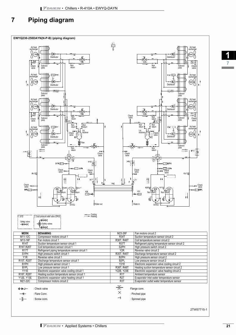
EWYQ230-250DAYN(N-P-B) (piping diagram)
2TW57715-1
MERK BENAMING M23-26F Fan motors circuit 2M11-12C Compressor motors circuit 1 R34T Suction temperature sensor circuit 2M13-16F Fan motors circuit 1 R36T, R46T Coil temperature sensor circuit 2
R14T Suction temperature sensor circuit 1 R37T Refrigerant piping temperature sensor circuit 2R16T,R26T Coil temperature sensor circuit 1 S2PH High pressure switch circuit 2
R17T Refrigerant piping temperature sensor circuit 1 Y2R Reverse valve circuit 2S1PH High pressure switch circuit 1 R35T, R45T Discharge temperature sensor circuit 2Y1R Reverse valve circuit 1 B2PH High pressure sensor circuit 2
R15T, R25T Discharge temperature sensor circuit 1 B2PL Low pressure sensor circuit 2B1PH High pressure sensor circuit 1 Y21E Electronic expansion valve cooling circuit 2B1PL Low pressure sensor circuit 1 R38T, R48T Heating suction temperature sensor circuit 2Y11E Electronic expansion valve cooling circuit 1 Y22E, Y23E Electronic expansion valve heating circuit 2
R18T, R28T Heating suction temperature sensor circuit 1 R1T Ambient temperature sensorY12E, Y13E Electronic expansion valve heating circuit 1 R2T Evaporator inlet water temperature sensor
M21-22C Compressor motors circuit 2 R3T Evaporator outlet water temperature sensor
: Check valve Flange conn.
: Flare Conn. : Pinched pipe
: Screw conn. : Spinned pipe
Air heat exchanger
Air heat exchanger
Air heat exchanger
Air heat exchanger
Check valve
Check valve
Nonreturn
Nonreturn
Nonreturn
Nonreturn
Distributor
Distributor
Distributor
Subcool pass
Subcool pass
Subcool pass
Subcool pass
Check valve
Check valve
Liq receiver
Filter
Check valve
Nonreturn
Check valve
Check valve
Check valve
Non returnNon return
Water inWater out
CoolingHeating
Nonreturn
Distributor
Distributor
Distributor
Distributor
Check valve
Check valve
Air heat exchanger
Air heat exchanger
Air heat exchanger
Air heat exchanger
Subcool pass
Subcool pass
Subcool pass
Subcool pass
LiqreceiverCheck
valve
Non return Non return
Check valve
Nonreturn
Nonreturn
Nonreturn
Nonreturn
Oil EQOil EQ
Safety valveSafety valves
1. STD 2. Dual pressure relief valve (OP03)
Distributor
Check valve
Check valve
Check valve
• Applied Systems • Chillers 21
• Chillers • R-410A • EWYQ-DAYN
17
22
7 Piping diagram
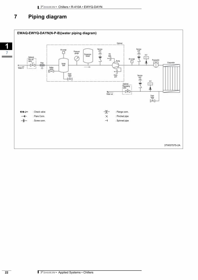
EWAQ-EWYQ-DAYN(N-P-B)(water piping diagram)
3TW57575-2A
Water in
Filter
OptionalShut offvalve
: Check valve : Flange conn.
: Flare Conn. : Pinched pipe
: Screw conn. : Spinned pipe
Air purge
Buffertank
Safetyvalve
Drainvalve
Pressuregauge
Expansionvessel
Serviceport
Fillport
Pump
Drainport
Air purge
Serviceport
Flowswitch
Evaporator
Drainvalve
Serviceport
OptionalRegulatingvalve
Water out
Optional
• Applied Systems • Chillers
3
18
• Chillers • R-410A • EWYQ-DAYN
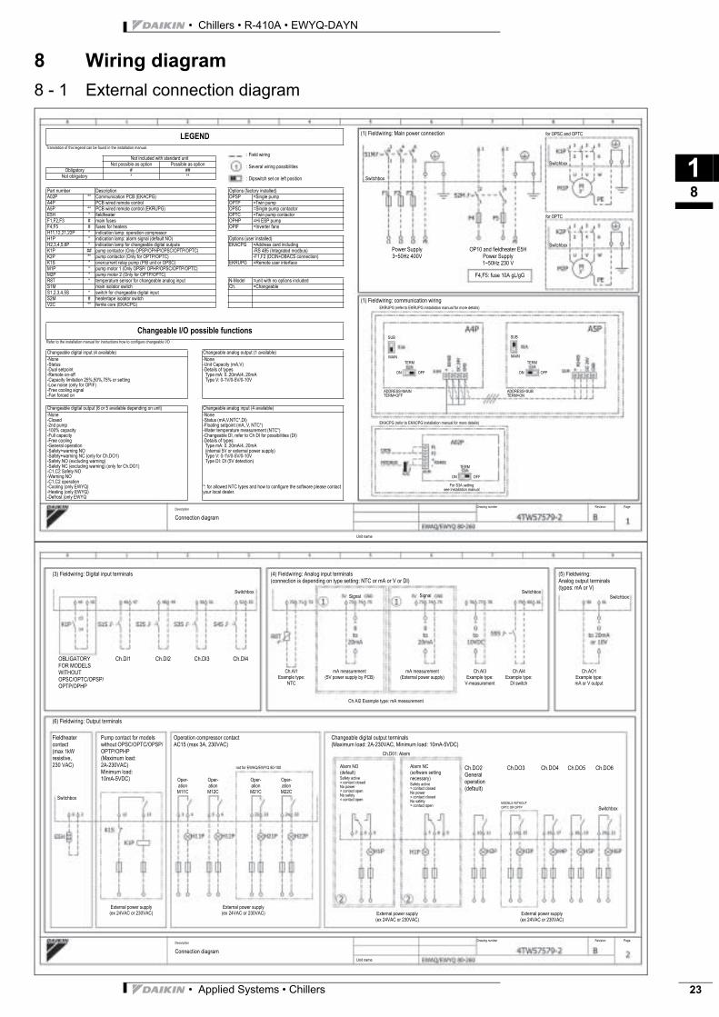
8 Wiring diagram
8 - 1 External connection diagramTranslation of this legend can be found in the installation manual.
Refer to the installation manual for instructions how to configure changeable I/O
LEGEND
Not included with standard unitNot possible as option Possible as option
Obligatory # ##Not obligatory * **
Part number Description Options (factory installed)A02P ** Communication PCB (EKACPG) OPSP =Single pumpA4P PCB wired remote control OPTP =Twin pumpA5P ** PCB wired remote control (EKRUPG) OPSC =Single pump contactorE5H * fieldheater OPTC =Twin pump contactorF1,F2,F3 # main fuses OPHP =Hi ESP pumpF4,F5 # fuses for heaters OPIF =Inverter fansH11,12,21,22P * indication lamp: operation compressorH1P * indication lamp: alarm signal (default NO) Options (user installed)H2,3,4,5,6P * indication lamp for changeable digital outputs EKACPG =Address card includingK1P ## pump contactor (Only OPSP/OPHP/OPSC/OPTP/OPTC) -RS 485 (Integrated modbus)K2P ** pump contactor (Only for OPTP/OPTC) -F1,F2 (DCIN+DBACS connection)K1S * overcurrent relay pump (P/B unit or OPSC) EKRUPG =Remote user interfaceM1P * pump motor 1 (Only OPSP/ OPHP/OPSC/OPTP/OPTC)M2P * pump motor 2 (Only for OPTP/OPTC)R8T * temperature sensor for changeable analog input N-Model =unit with no options includedS1M main isolator switch Ch. =ChangeableS1,2,3,4,5S * switch for changeable digital inputS2M # heatertape isolator switchV2C ** ferrite core (EKACPG)
Changeable I/O possible functions
Changeable digital input (4 available) Changeable analog output (1 available)
-None-Status-Dual setpoint-Remote on-off-Capacity limitation 25%,50%,75% or setting-Low noise (only for OPIF)-Free cooling signal-Fan forced on
-None-Unit Capacity (mA,V)-Details of types Type mA: 0..20mA/4..20mA Type V: 0-1V/0-5V/0-10V
Changeable digital output (6 or 5 available depending on unit) Changeable analog input (4 available)
-None-Closed-2nd pump-100% capacity-Full capacity-Free cooling-General operation-Safety+warning NO-Safety+warning NC (only for Ch.DO1)-Safety NO (excluding warning)-Safety NC (excluding warning) (only for Ch.DO1)-C1,C2 Safety NO-Warning NO-C1,C2 operation-Cooling (only EWYQ)-Heating (only EWYQ)-Defrost (only EWYQ
-None-Status (mA,V,NTC*,DI)-Floating setpoint (mA, V, NTC*)-Water temperature measurement (NTC*)-Changeable DI, refer to Ch DI for possibilities (DI)-Details of types: Type mA: 0..20mA/4..20mA (internal 5V or external power supply) Type V: 0-1V/0-5V/0-10V Type DI: DI (5V detection)
*: for allowed NTC types and how to configure the software please contact your local dealer.
: Field wiring
: Several wiring possibilities
: Dipswitch set on left position
(1) Fieldwiring: Main power connection
Switchbox
Power Supply3~50Hz 400V
OP10 and fieldheater E5HPower Supply1~50Hz 230 V
F4,F5: fuse 10A gL/gG
Switchbox
Switchbox
for OPSC and OPTC
for OPTC
(1) Fieldwiring: communication wiringEKRUPG (refer to EKRUPG installation manual for more details)
ADDRESS=MAINTERM=OFF
EKACPG (refer to EKACPG installation manual for more details)
ADDRESS=SUBTERM=ON
For S3A settingsee installation manual
MAIN
SUB
TERM
ON OFF
MAIN
SUB
TERM
ON OFF
TERM
ON OFF
Unit name
Description
Connection diagram
Drawing number Revision Page
(3) Fieldwiring: Digital input terminals (4) Fieldwiring: Analog input terminals(connection is depending on type setting: NTC or mA or V or DI)
(5) Fieldwiring:Analog output terminals(types: mA or V)
OBLIGATORY Ch.DI1 Ch.DI2 Ch.DI3 Ch.DI4FOR MODELSWITHOUTOPSC/OPTC/OPSP/OPTP/OPHP
SwitchboxSignal Signal
Ch.AI1Example type:
NTC
mA measurement(5V power supply by PCB)
mA measurement(External power supply)
Ch.AI2 Example type: mA measurement
Ch.AI3Example type:
V-measurement
Ch.AI4Example type:
DI switch
Ch.AO1Example type:mA or V output
SwitchboxSwitchbox
Fieldheatercontact(max 1kW resistive,230 VAC)
Pump contact for modelswithout OPSC/OPTC/OPSP/OPTP/OPHP(Maximum load:2A-230VAC)Minimum load:10mA-5VDC)
Operation compressor contactAC15 (max 3A, 230VAC)
Oper-ationM11C
Oper-ationM12C
Oper-ationM21C
Oper-ationM22C
Unit name
Switchbox
External power supply(ex 24VAC or 230VAC)
External power supply(ex 24VAC or 230VAC) External power supply
(ex 24VAC or 230VAC)External power supply(ex 24VAC or 230VAC)
Changeable digital output terminals(Maximum load: 2A-230VAC, Minimum load: 10mA-5VDC)
Alarm NO(default)Safety active= contact closedNo power= contact openNo safety= contact open
Alarm NC(software setting necessary)Safety active= contact closedNo power= contact closedNo safety= contact open
Ch.DO2 Ch.DO3 Ch.DO4 Ch.DO5 Ch.DO6Generaloperation(default)
MODELS WITHOUT
OPTC OR OPTP Switchbox
Description
Connection diagram
Drawing number Revision Page
(6) Fieldwiring: Output terminals
not for EWAQ/EWYQ 80-100
Ch.D01: Alarm
• Applied Systems • Chillers 23
• Chillers • R-410A • EWYQ-DAYN
19
24
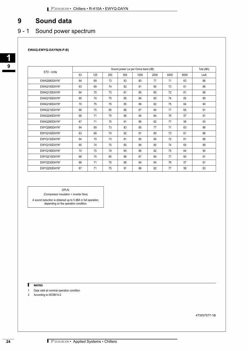
9 Sound data
9 - 1 Sound power spectrumEWAQ-EWYQ-DAYN(N-P-B)
NOTES
1 Data valid at nominal operation condition
2 According to ISO9614-2
4TW57577-1B
STD - UnitsSound power Lw per Octva band (dB) Total (dBA)
63 125 250 500 1000 2000 4000 8000 LwA
EWAQ080DAYN* 64 69 73 83 80 77 71 63 86
EWAQ100DAYN* 63 69 74 82 81 80 73 61 86
EWAQ130DAYN* 64 70 73 81 85 80 72 61 88
EWAQ150DAYN* 65 74 75 85 84 80 74 65 89
EWAQ180DAYN* 70 75 79 85 86 82 75 64 90
EWAQ210DAYN* 68 75 80 86 87 84 77 65 91
EWAQ240DAYN* 66 71 75 88 84 84 76 57 91
EWAQ260DAYN* 67 71 75 91 86 82 77 58 93
EWYQ080DAYN* 64 69 73 83 80 77 71 63 86
EWYQ100DAYN* 63 69 74 82 81 80 73 61 86
EWYQ130DAYN* 64 70 73 81 85 80 72 61 88
EWYQ150DAYN* 65 74 75 85 84 80 74 65 89
EWYQ180DAYN* 70 75 79 85 86 82 75 64 90
EWYQ210DAYN* 68 75 80 86 87 84 77 65 91
EWYQ230DAYN* 66 71 75 88 84 84 76 57 91
EWYQ250DAYN* 67 71 75 91 86 82 77 58 93
OPLN:
(Compressor insulation + inverter fans)
A sound reduction is obtained up to 5 dBA in full operation, depending on the operation condition.
• Applied Systems • Chillers
3
110
• Chillers • R-410A • EWYQ-DAYN
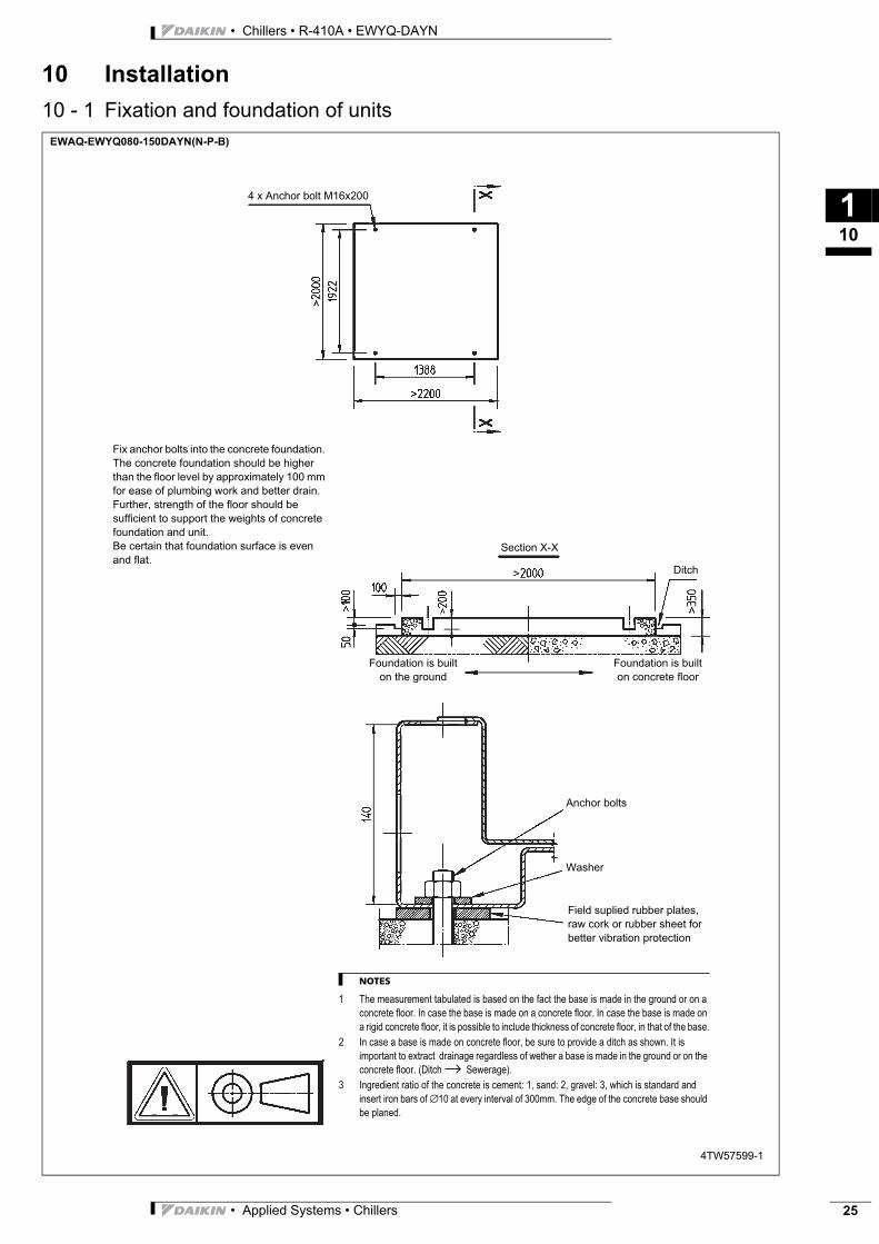
10 Installation
10 - 1 Fixation and foundation of unitsEWAQ-EWYQ080-150DAYN(N-P-B)
4TW57599-1
Fix anchor bolts into the concrete foundation.
The concrete foundation should be higher
than the floor level by approximately 100 mm
for ease of plumbing work and better drain.
Further, strength of the floor should be
sufficient to support the weights of concrete
foundation and unit.
Be certain that foundation surface is even
and flat.
NOTES
1 The measurement tabulated is based on the fact the base is made in the ground or on a
concrete floor. In case the base is made on a concrete floor. In case the base is made on
a rigid concrete floor, it is possible to include thickness of concrete floor, in that of the base.
2 In case a base is made on concrete floor, be sure to provide a ditch as shown. It is
important to extract drainage regardless of wether a base is made in the ground or on the
concrete floor. (Ditch → Sewerage).
3 Ingredient ratio of the concrete is cement: 1, sand: 2, gravel: 3, which is standard and
insert iron bars of ∅10 at every interval of 300mm. The edge of the concrete base should
be planed.
4 x Anchor bolt M16x200
Section X-X
Foundation is built
on the ground
Foundation is built
on concrete floor
Ditch
Anchor bolts
Washer
Field suplied rubber plates,
raw cork or rubber sheet for
better vibration protection
• Applied Systems • Chillers 25
• Chillers • R-410A • EWYQ-DAYN
110
26
10 Installation
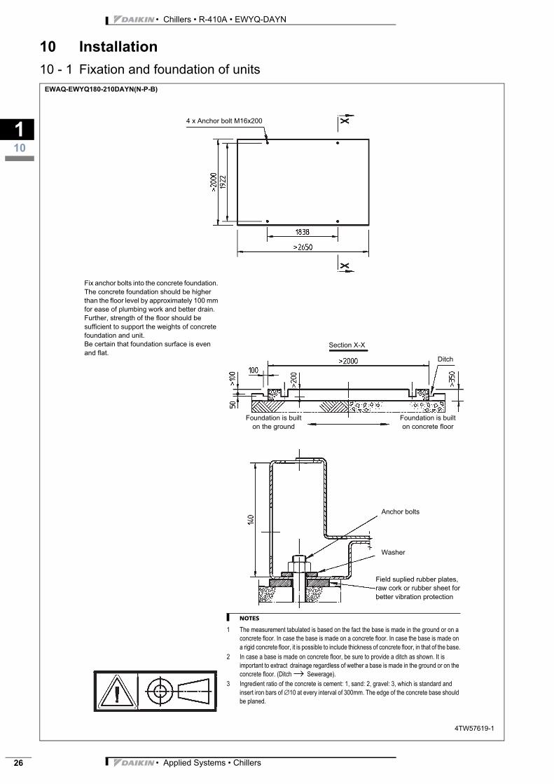
10 - 1 Fixation and foundation of unitsEWAQ-EWYQ180-210DAYN(N-P-B)
4TW57619-1
Fix anchor bolts into the concrete foundation.
The concrete foundation should be higher
than the floor level by approximately 100 mm
for ease of plumbing work and better drain.
Further, strength of the floor should be
sufficient to support the weights of concrete
foundation and unit.
Be certain that foundation surface is even
and flat.
NOTES
1 The measurement tabulated is based on the fact the base is made in the ground or on a
concrete floor. In case the base is made on a concrete floor. In case the base is made on
a rigid concrete floor, it is possible to include thickness of concrete floor, in that of the base.
2 In case a base is made on concrete floor, be sure to provide a ditch as shown. It is
important to extract drainage regardless of wether a base is made in the ground or on the
concrete floor. (Ditch → Sewerage).
3 Ingredient ratio of the concrete is cement: 1, sand: 2, gravel: 3, which is standard and
insert iron bars of ∅10 at every interval of 300mm. The edge of the concrete base should
be planed.
4 x Anchor bolt M16x200
Section X-X
Foundation is built
on the ground
Foundation is built
on concrete floor
Ditch
Anchor bolts
Washer
Field suplied rubber plates,
raw cork or rubber sheet for
better vibration protection
• Applied Systems • Chillers

3
110
• Chillers • R-410A • EWYQ-DAYN
10 Installation
10 - 1 Fixation and foundation of unitsEWAQ240-260DAYN(N-P-B)_EWYQ230-250DAYN(N-P-B)
4TW57639-1
Fix anchor bolts into the concrete foundation.
The concrete foundation should be higher
than the floor level by approximately 100 mm
for ease of plumbing work and better drain.
Further, strength of the floor should be
sufficient to support the weights of concrete
foundation and unit.
Be certain that foundation surface is even
and flat.
NOTES
1 The measurement tabulated is based on the fact the base is made in the ground or on a
concrete floor. In case the base is made on a rigid concrete floor, it is possible to include
thickness of concrete floor in that of the base.
2 In case a base is made on concrete floor, be sure to provide a ditch as shown. It is
important to extract drainage regardless of wether a base is made in the ground or on the
concrete floor. (Ditch → Sewerage).
3 Ingredient ratio of the concrete is cement: 1, sand:2, gravel:3, which is standard and insert
iron bars of ∅10 at every interval of 300mm. The edge of the concrete base should be
planed.
8x Anchor bolt M16 x 200
Section X-X
Foundation is built
on the grond
Foundation is built
on concrete floor
Anchor bolts
Washer
Field suplied rubber plates,
raw cork or rubber sheet for
better vibration protection
Ditch
• Applied Systems • Chillers 27
• Chillers • R-410A • EWYQ-DAYN
110
28
10 Installation
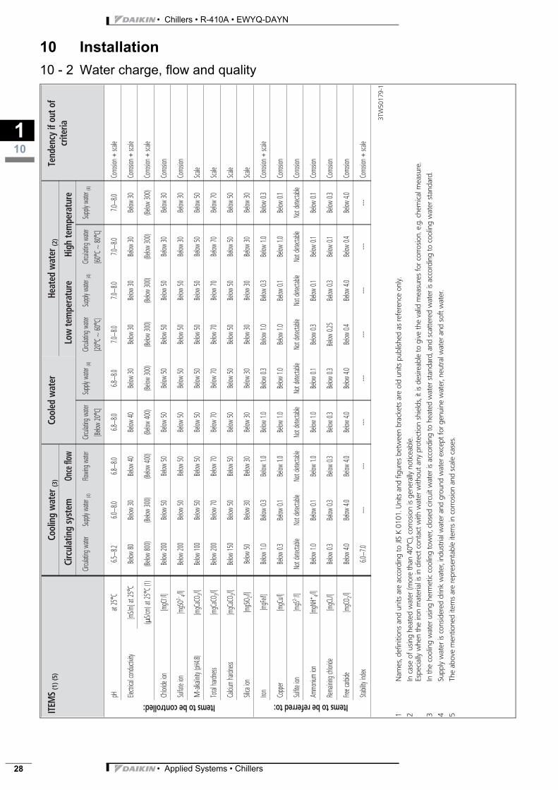
10 - 2 Water charge, flow and qualityITEM
S(1
)(5)
Cool
ing
wat
er(3
)Co
oled
wat
erHe
ated
wat
er(2
)Te
nden
cyif
outo
fcr
iteria
Circ
ulat
ing
syst
emOn
ceflo
wLo
wte
mpe
ratu
reHi
ghte
mpe
ratu
re
Circul
ating
water
Supp
lywa
ter(4)
Flowin
gwate
rCir
culati
ngwa
ter
[Below
20°C
]
Supp
lywa
ter(4)
Circul
ating
water
[20°C
∼60
°C]
Supp
lywa
ter(4)
Circul
ating
water
[60°C
∼80
°C]
Supp
lywa
ter(4)
pHat
25°C
6.5∼8
.26.0
∼8.0
6.8∼8
.06.8
∼8.0
6.8∼8
.07.0
∼8.0
7.0∼8
.07.0
∼8.0
7.0∼8
.0Co
rrosio
n+sca
le
Electr
icalc
ondu
ctivity
[mS/m
]at2
5°C
Below
80Be
low30
Below
40Be
low40
Below
30Be
low30
Below
30Be
low30
Below
30Co
rrosio
n+sca
le
(μS/c
m)at
25°C
(1)(Be
low80
0)(Be
low30
0)(Be
low40
0)(Be
low40
0)(Be
low30
0)(Be
low30
0)(Be
low30
0)(Be
low30
0)(Be
low30
0)Co
rrosio
n+sca
le
Chlor
ideion
[mgC
I- /l]Be
low20
0Be
low50
Below
50Be
low50
Below
50Be
low50
Below
50Be
low30
Below
30Co
rrosio
n
Sulfa
teion
[mgS
O2-4/l]
Below
200
Below
50Be
low50
Below
50Be
low50
Below
50Be
low50
Below
30Be
low30
Corro
sion
M-al
kalini
ty(pH
4.8)
[mgC
aCO 3
/l]Be
low10
0Be
low50
Below
50Be
low50
Below
50Be
low50
Below
50Be
low50
Below
50Sca
le
Total
hardn
ess[m
gCaC
O 3/l]
Below
200
Below
70Be
low70
Below
70Be
low70
Below
70Be
low70
Below
70Be
low70
Scale
Calciu
mha
rdness
[mgC
aCO 3
/l]Be
low15
0Be
low50
Below
50Be
low50
Below
50Be
low50
Below
50Be
low50
Below
50Sca
le
Silica
ion[m
gSiO 2
/l]Be
low50
Below
30Be
low30
Below
30Be
low30
Below
30Be
low30
Below
30Be
low30
Scale
Iron
[mgF
e/l]
Below
1.0Be
low0.3
Below
1.0Be
low1.0
Below
0.3Be
low1.0
Below
0.3Be
low1.0
Below
0.3Co
rrosio
n+sca
le
Copp
er[m
gCu/l
]Be
low0.3
Below
0.1Be
low1.0
Below
1.0Be
low1.0
Below
1.0Be
low0.1
Below
1.0Be
low0.1
Corro
sion
Sulfit
eion
[mgS
2-/l]
Notd
etecta
bleNo
tdete
ctable
Notd
etecta
bleNo
tdete
ctable
Notd
etecta
bleNo
tdete
ctable
Notd
etecta
bleNo
tdete
ctable
Notd
etecta
bleCo
rrosio
n
Ammo
nium
ion[m
gNH+ 4/l]
Below
1.0Be
low0.1
Below
1.0Be
low1.0
Below
0.1Be
low0.3
Below
0.1Be
low0.1
Below
0.1Co
rrosio
n
Rema
iningc
hlorid
e[m
gCL/l]
Below
0.3Be
low0.3
Below
0.3Be
low0.3
Below
0.3Be
low0.2
5Be
low0.3
Below
0.1Be
low0.3
Corro
sion
Freec
arbide
[mgC
O 2/l]
Below
4.0Be
low4.0
Below
4.0Be
low4.0
Below
0.4Be
low4.0
Below
0.4Be
low4.0
Corro
sion
Stabili
tyind
ex6.0
∼7.0
------
------
------
---Co
rrosio
n+sca
le
3TW
5017
9-1
1N
ames
,def
initi
ons
and
units
are
acco
rdin
gto
JISK
0101
.Uni
tsan
dfig
ures
betw
een
brac
kets
are
old
units
publ
ished
asre
fere
nce
only
.
2In
case
ofus
ing
heat
edw
ater
(mor
eth
an40
°C),
corro
sion
isge
nera
llyno
ticea
ble.
Espe
cial
lyw
hen
the
iron
mat
eria
lis
indi
rect
cont
actw
ithw
ater
with
outa
nypr
otec
tion
shie
lds,
itis
desir
eabl
eto
give
the
valid
mea
sure
sfo
rcor
rosio
n.e.
g.ch
emic
alm
easu
re.
3In
the
cool
ing
wat
erus
ing
herm
etic
cool
ing
tow
er,c
lose
dci
rcui
twat
eris
acco
rdin
gto
heat
edw
ater
stan
dard
,and
scat
tere
dw
ater
isac
cord
ing
toco
olin
gw
ater
stan
dard
.
4Su
pply
wat
eris
cons
ider
eddr
ink
wat
er,i
ndus
trial
wat
eran
dgr
ound
wat
erex
cept
forg
enui
new
ater
,neu
tralw
ater
and
soft
wat
er.
5Th
eab
ove
men
tione
dite
ms
are
repr
esen
tabl
eite
ms
inco
rrosio
nan
dsc
ale
case
s.
Itemstobecontrolled: Itemstobereferred to:
---
Below
4.0
• Applied Systems • Chillers
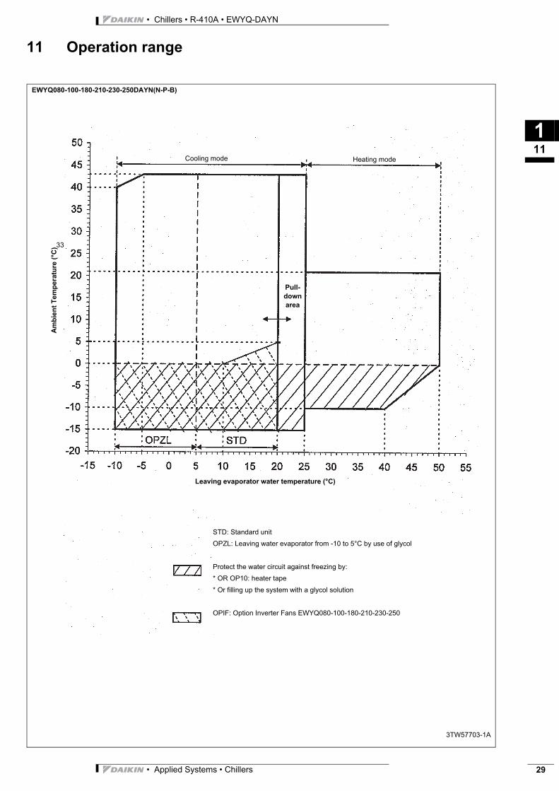
3
111
• Chillers • R-410A • EWYQ-DAYN
11 Operation range
Leaving evaporator water temperature (°C)
STD: Standard unit
OPZL: Leaving water evaporator from -10 to 5°C by use of glycol
Protect the water circuit against freezing by:
* OR OP10: heater tape
* Or filling up the system with a glycol solution
OPIF: Option Inverter Fans EWYQ080-100-180-210-230-250
Pull-
down
area
Heating modeCooling mode
Am
bie
nt
Te
mp
era
ture
(°C
)33
3TW57703-1A
EWYQ080-100-180-210-230-250DAYN(N-P-B)
• Applied Systems • Chillers 29
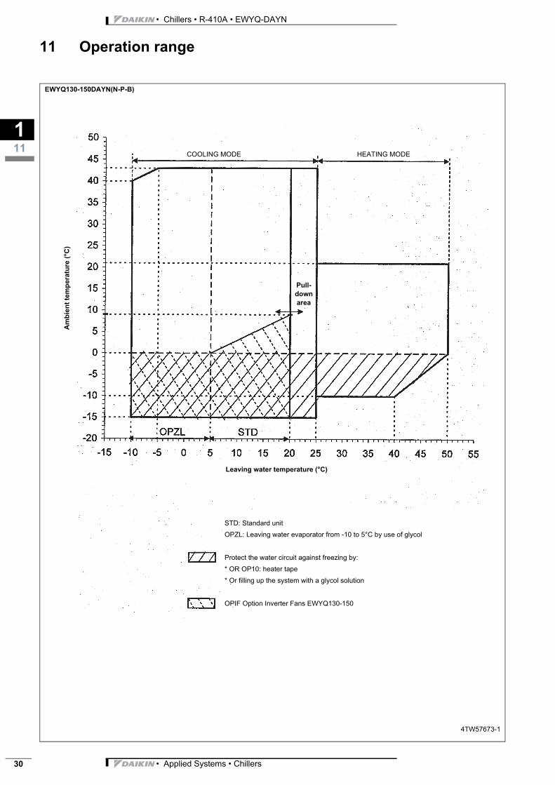
• Chillers • R-410A • EWYQ-DAYN
111
30
11 Operation range
EWYQ130-150DAYN(N-P-B)
4TW57673-1
Leaving water temperature (°C)
STD: Standard unit
OPZL: Leaving water evaporator from -10 to 5°C by use of glycol
Protect the water circuit against freezing by:
* OR OP10: heater tape
* Or filling up the system with a glycol solution
OPIF Option Inverter Fans EWYQ130-150
Pull-
down
area
COOLING MODE HEATING MODE
Am
bie
nt
tem
pera
ture
(°C
)
• Applied Systems • Chillers
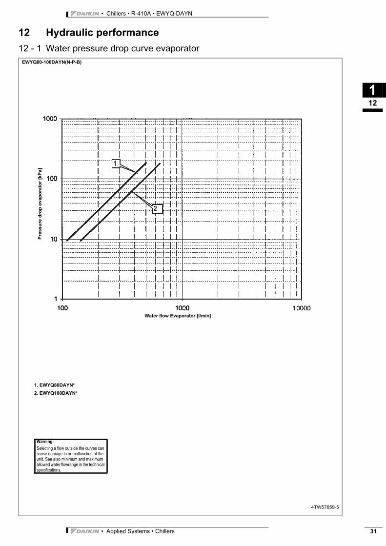
3
112
• Chillers • R-410A • EWYQ-DAYN
12 Hydraulic performance
12 - 1 Water pressure drop curve evaporatorEWYQ80-100DAYN(N-P-B)
4TW57659-5
Water flow Evaporator [l/min]
1. EWYQ80DAYN*
2. EWYQ100DAYN*
Warning:
Selecting a flow outside the curves can cause damage to or malfunction of the unit. See also minimum and maximum allowed water flowrange in the technical specifications.
Pre
ssu
re d
rop
ev
ap
ora
tor
[kP
a]
• Applied Systems • Chillers 31
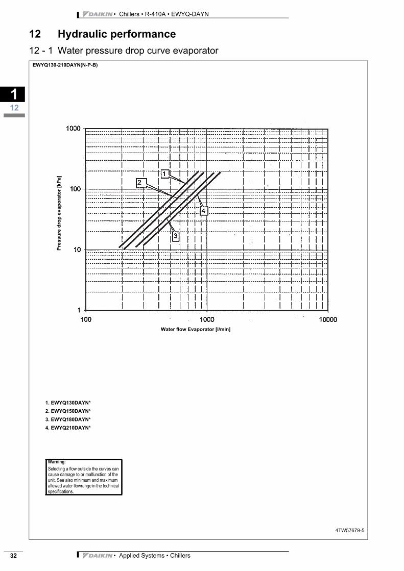
• Chillers • R-410A • EWYQ-DAYN
112
32
12 Hydraulic performance
12 - 1 Water pressure drop curve evaporatorEWYQ130-210DAYN(N-P-B)
4TW57679-5
Water flow Evaporator [l/min]
1. EWYQ130DAYN*
2. EWYQ150DAYN*
3. EWYQ180DAYN*
4. EWYQ210DAYN*
Warning:
Selecting a flow outside the curves can cause damage to or malfunction of the unit. See also minimum and maximum allowed water flowrange in the technical specifications.
Pre
ssu
re d
rop
ev
ap
ora
tor
[kP
a]
• Applied Systems • Chillers
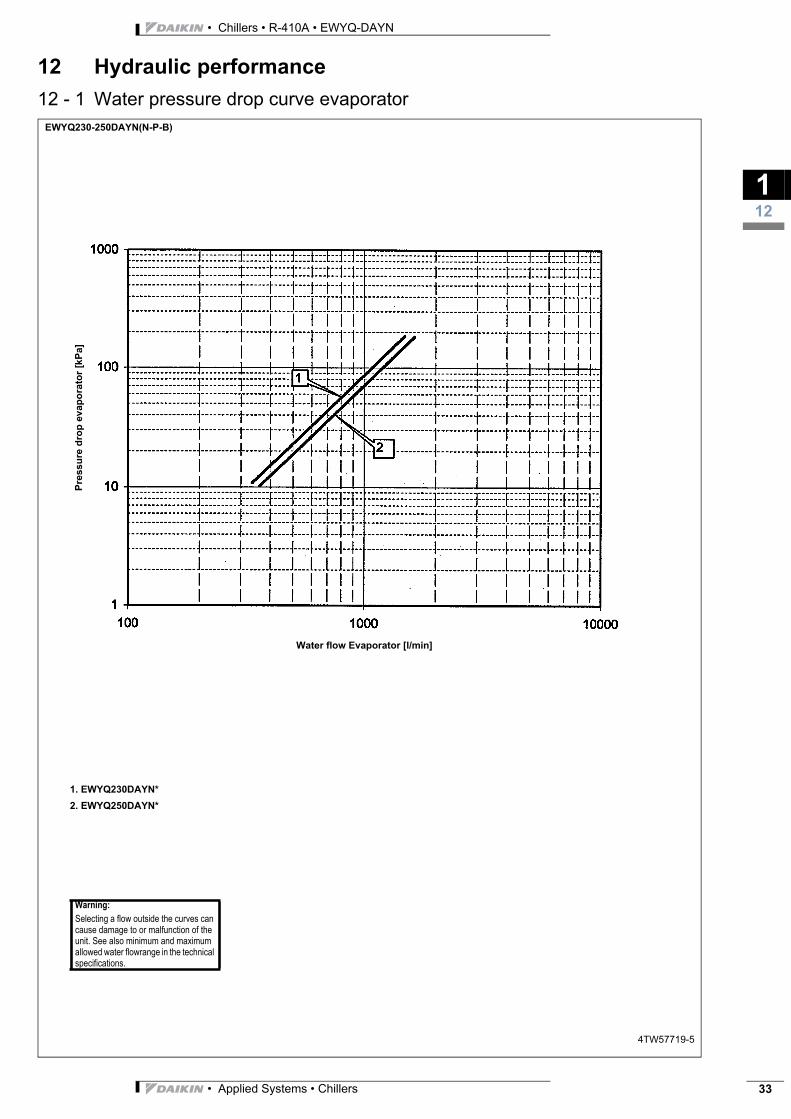
3
112
• Chillers • R-410A • EWYQ-DAYN
12 Hydraulic performance
12 - 1 Water pressure drop curve evaporatorEWYQ230-250DAYN(N-P-B)
4TW57719-5
Water flow Evaporator [l/min]
1. EWYQ230DAYN*
2. EWYQ250DAYN*
Warning:
Selecting a flow outside the curves can cause damage to or malfunction of the unit. See also minimum and maximum allowed water flowrange in the technical specifications.
Pre
ssu
re d
rop
ev
ap
ora
tor
[kP
a]
• Applied Systems • Chillers 33
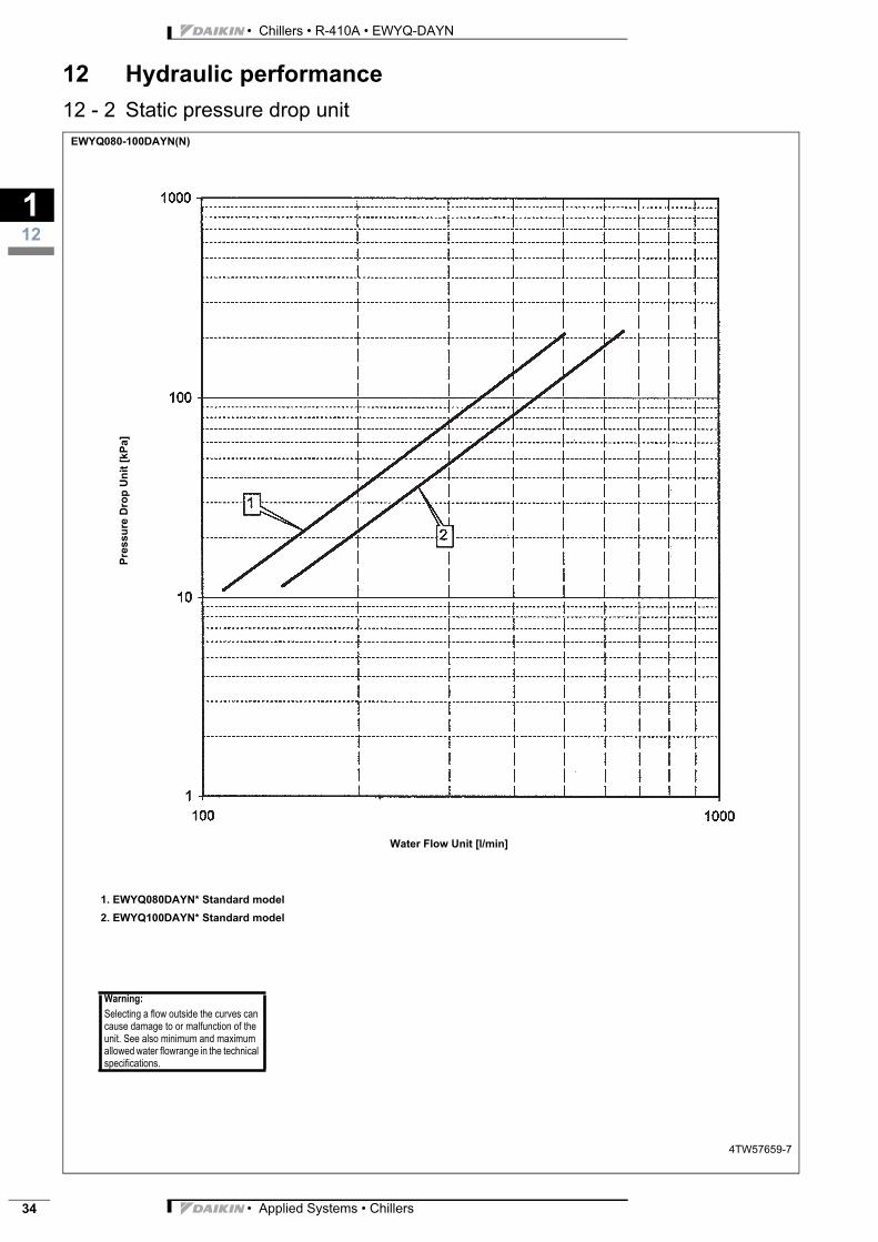
• Chillers • R-410A • EWYQ-DAYN
112
34
12 Hydraulic performance
12 - 2 Static pressure drop unitEWYQ080-100DAYN(N)
4TW57659-7
Water Flow Unit [l/min]
1. EWYQ080DAYN* Standard model
2. EWYQ100DAYN* Standard model
Warning:
Selecting a flow outside the curves can cause damage to or malfunction of the unit. See also minimum and maximum allowed water flowrange in the technical specifications.
Pre
ssu
re D
rop
Un
it [
kP
a]
• Applied Systems • Chillers
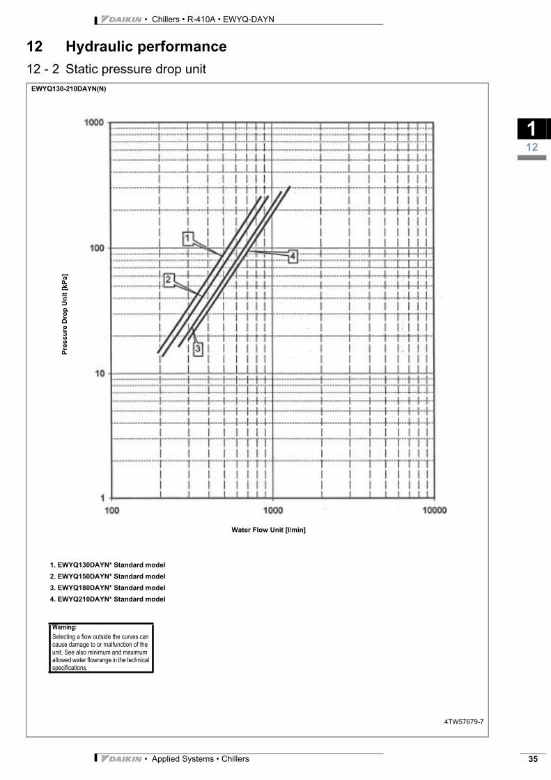
3
112
• Chillers • R-410A • EWYQ-DAYN
12 Hydraulic performance
12 - 2 Static pressure drop unitEWYQ130-210DAYN(N)
4TW57679-7
Water Flow Unit [l/min]
1. EWYQ130DAYN* Standard model
2. EWYQ150DAYN* Standard model
3. EWYQ180DAYN* Standard model
4. EWYQ210DAYN* Standard model
Warning:
Selecting a flow outside the curves can cause damage to or malfunction of the unit. See also minimum and maximum allowed water flowrange in the technical specifications.
Pre
ssu
re D
rop
Un
it [
kP
a]
• Applied Systems • Chillers 35
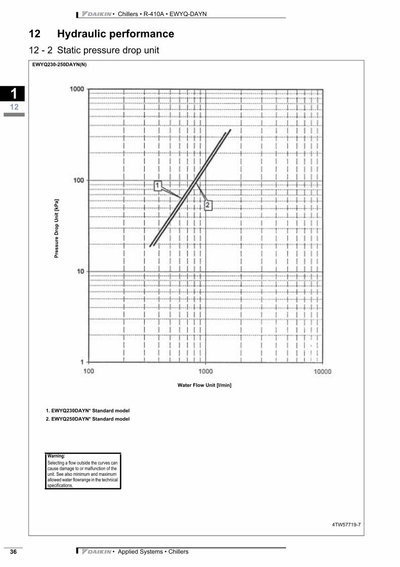
• Chillers • R-410A • EWYQ-DAYN
112
36
12 Hydraulic performance
12 - 2 Static pressure drop unitEWYQ230-250DAYN(N)
4TW57719-7
Water Flow Unit [l/min]
1. EWYQ230DAYN* Standard model
2. EWYQ250DAYN* Standard model
Warning:
Selecting a flow outside the curves can cause damage to or malfunction of the unit. See also minimum and maximum allowed water flowrange in the technical specifications.
Pre
ssu
re D
rop
Un
it [
kP
a]
• Applied Systems • Chillers
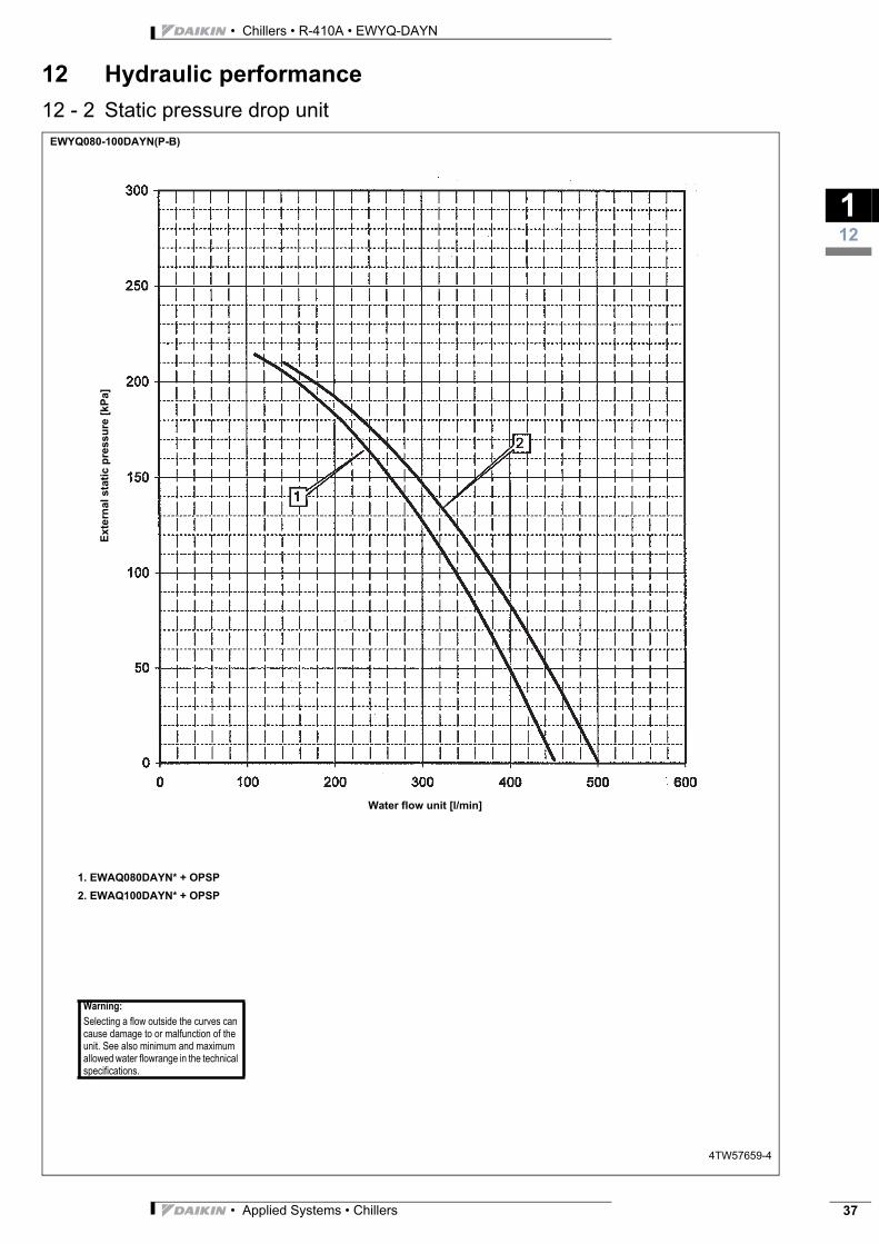
3
112
• Chillers • R-410A • EWYQ-DAYN
12 Hydraulic performance
12 - 2 Static pressure drop unitEWYQ080-100DAYN(P-B)
4TW57659-4
Water flow unit [l/min]
1. EWAQ080DAYN* + OPSP
2. EWAQ100DAYN* + OPSP
Warning:
Selecting a flow outside the curves can cause damage to or malfunction of the unit. See also minimum and maximum allowed water flowrange in the technical specifications.
Ex
tern
al
sta
tic
pre
ss
ure
[k
Pa]
• Applied Systems • Chillers 37
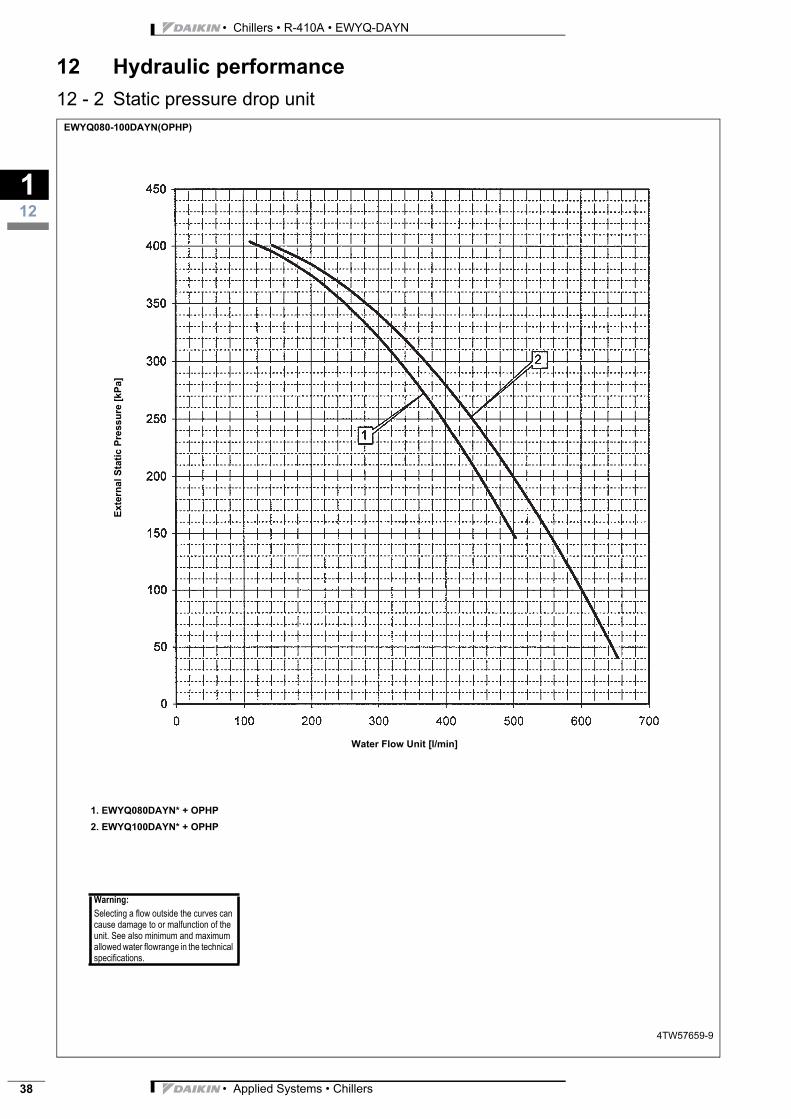
• Chillers • R-410A • EWYQ-DAYN
112
38
12 Hydraulic performance
12 - 2 Static pressure drop unitEWYQ080-100DAYN(OPHP)
4TW57659-9
Water Flow Unit [l/min]
Exte
rnal
Sta
tic
Pre
ss
ure
[k
Pa
]
1. EWYQ080DAYN* + OPHP
2. EWYQ100DAYN* + OPHP
Warning:
Selecting a flow outside the curves can cause damage to or malfunction of the unit. See also minimum and maximum allowed water flowrange in the technical specifications.
• Applied Systems • Chillers
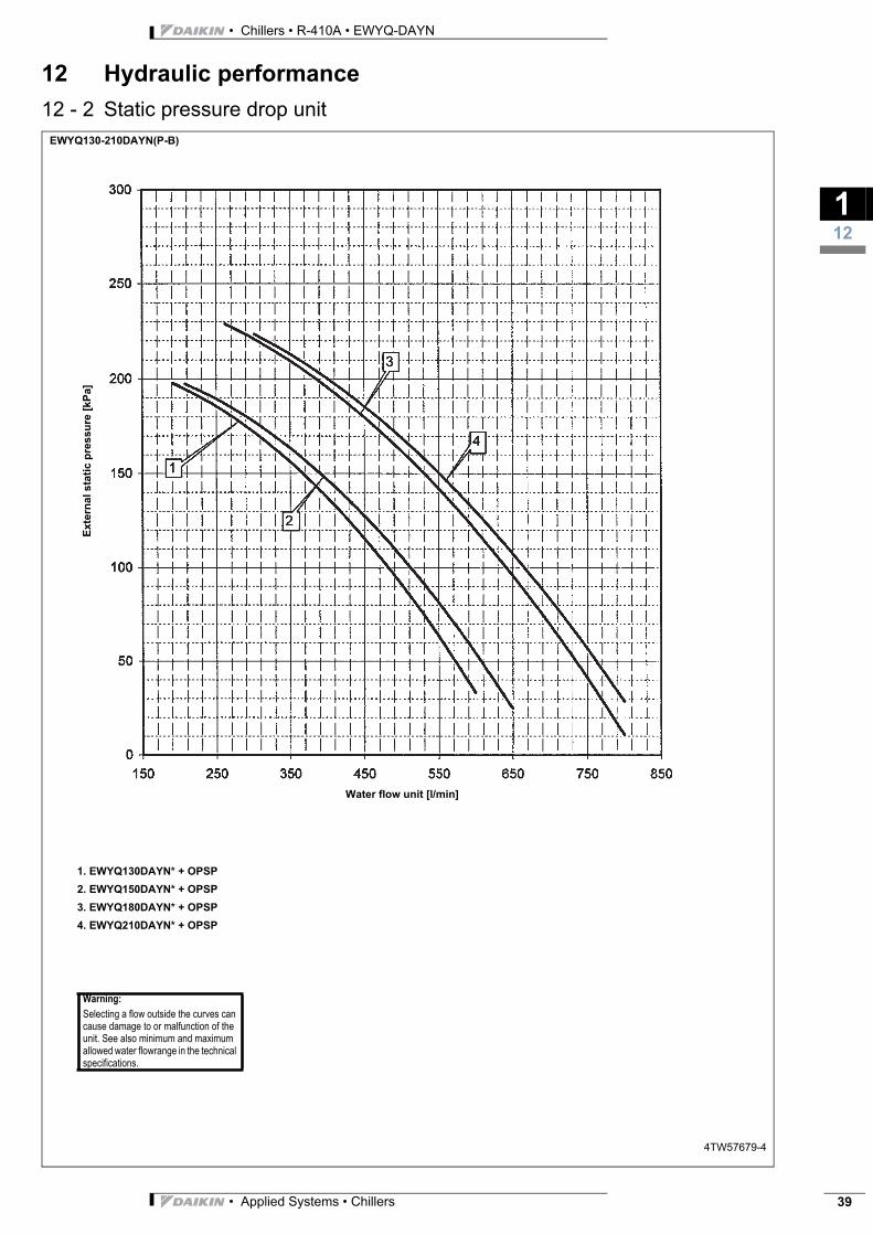
3
112
• Chillers • R-410A • EWYQ-DAYN
12 Hydraulic performance
12 - 2 Static pressure drop unitEWYQ130-210DAYN(P-B)
4TW57679-4
Water flow unit [l/min]
1. EWYQ130DAYN* + OPSP
2. EWYQ150DAYN* + OPSP
3. EWYQ180DAYN* + OPSP
4. EWYQ210DAYN* + OPSP
Warning:
Selecting a flow outside the curves can cause damage to or malfunction of the unit. See also minimum and maximum allowed water flowrange in the technical specifications.
Exte
rna
l s
tati
c p
res
su
re [
kP
a]
• Applied Systems • Chillers 39

• Chillers • R-410A • EWYQ-DAYN
112
40
12 Hydraulic performance
12 - 2 Static pressure drop unitEWYQ130-210DAYN (OPHP)
4TW57679-9
Water Flow Unit [l/min]
1. EWYQ130DAYN* + OPHP
2. EWYQ150DAYN* + OPHP
3. EWYQ180DAYN* + OPHP
4. EWYQ210DAYN* + OPHP
Warning:
Selecting a flow outside the curves can cause damage to or malfunction of the unit. See also minimum and maximum allowed water flowrange in the technical specifications.
Exte
rna
l S
tati
c P
res
su
re [
kP
a]
• Applied Systems • Chillers
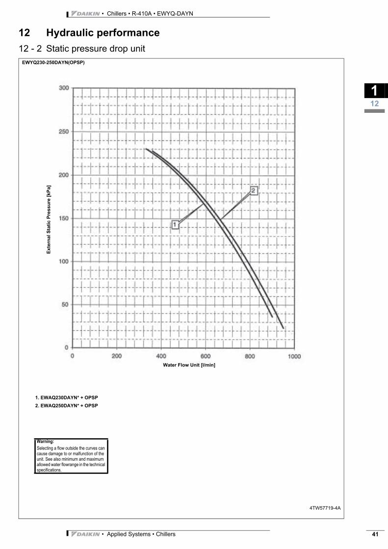
3
112
• Chillers • R-410A • EWYQ-DAYN
12 Hydraulic performance
12 - 2 Static pressure drop unitEWYQ230-250DAYN(OPSP)
4TW57719-4A
Water Flow Unit [l/min]
Exte
rnal
Sta
tic
Pre
ss
ure
[k
Pa
]
1. EWAQ230DAYN* + OPSP
2. EWAQ250DAYN* + OPSP
Warning:
Selecting a flow outside the curves can cause damage to or malfunction of the unit. See also minimum and maximum allowed water flowrange in the technical specifications.
• Applied Systems • Chillers 41
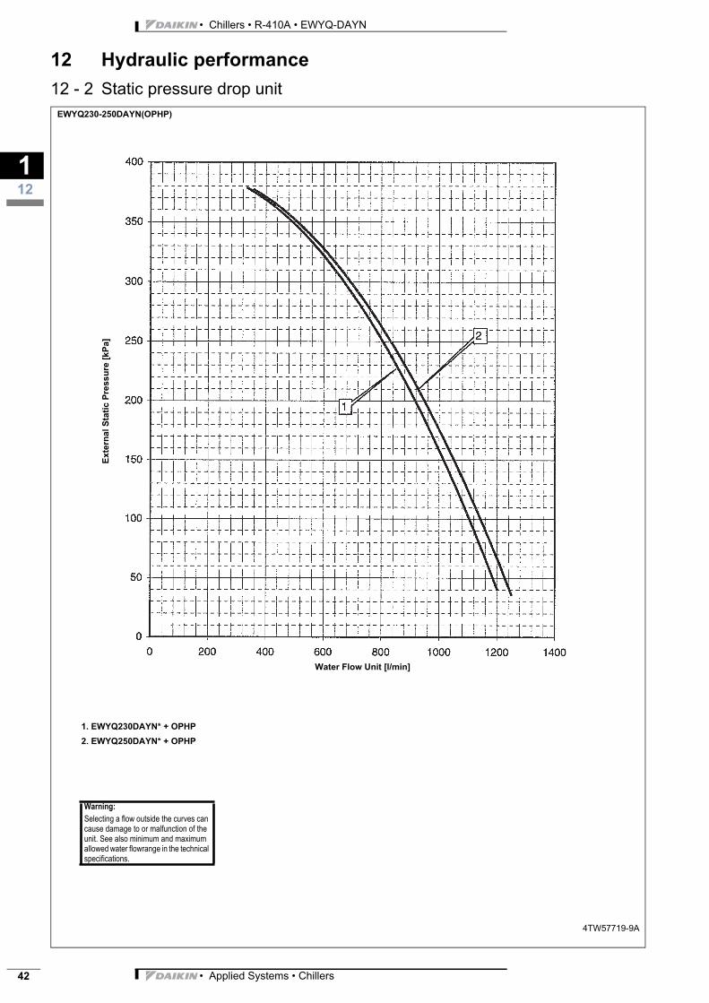
• Chillers • R-410A • EWYQ-DAYN
112
42
12 Hydraulic performance
12 - 2 Static pressure drop unitEWYQ230-250DAYN(OPHP)
4TW57719-9A
Water Flow Unit [l/min]
Exte
rnal
Sta
tic
Pre
ss
ure
[k
Pa
]
1. EWYQ230DAYN* + OPHP
2. EWYQ250DAYN* + OPHP
Warning:
Selecting a flow outside the curves can cause damage to or malfunction of the unit. See also minimum and maximum allowed water flowrange in the technical specifications.
• Applied Systems • Chillers
![TEKNISK INFORMATION - Thomas Concrete Group€¦ · TEKNISK INFORMATION - Thomas Concrete Group ... 50]](https://img.pdfslide.net/doc/110x75/60605ee8a32f4e70fd33470a/teknisk-information-thomas-concrete-group-teknisk-information-thomas-concrete.jpg)