Embed Size (px)
Citation preview

TECHNICAL DESCRIPTION
INSTALLATION INSTRUCTIONS RO-KA SILO MILK COOLING TANKS
10.000 - 40.000 Litres
3.000 - 9.000 Litres
13.06.2012

Table of Contents:
General Description Page 3 Agitator Page 4 Equipment for cleaning of the tank Page 5 Volume of water / Detergent Page 6 Silo tanks 10.000 - 40.000 Litres, Ø 3000 mm: Measurements Page 7 Silo tanks 3.000 - 9.000 Litres, Ø 2100 mm: Measurements Page 8 Pipes and connections 10.000 - 40.000 Litres Page 9 Pipes and connections 3.000 - 9.000 Litres Page 10 Foundation and recess for pipes Page 11 Placing the silo tank Page 12 Outdoor installation with milk chamber Page 13 Installation kit for outdoor silo Page 14 Silo installation for alcoves Page 15 Installation kit alcove Page 16 Indoor installation Page 17 Installation kit indoor Page 18 Receiving and unwrapping Page 19 Service and maintenance Page 20 Special accessories Page 21 Circuit diagram 1 Cooling unit Page 22 Circuit diagram 2 Cooling units Page 23 Connecting the agitator Page 24 Installation of the heater Page 25 9000S Diagram Page 26 Circuit diagram Danfoss HGZ unit Page 27

Page 3
RO-KA SILO TANKS
RO-KA Silo Tanks have been constructed based on the experience with the well-known RKC Milk Cooling Tanks produced over decades. RO-KA Silo Cooling Tanks are closed tanks designed as vertical cylinders with a conical bottom to ensure a perfect discharge of the tank.
The tanks are produced in sizes from 10.000 to 40.000 litres in standard dimensions or according to customer specifications. Since 2010 we are also producing silo tanks in sizes from 3.000 to 9.000 litres. The type description corresponds to the nominal content in litres of the tank. All metal parts consist of stainless steel of quality EN 1.4301 – AISI 304. The inside container is made of 2.0mm stainless steel and the outside jacket is made of 2.0mm stainless steel, too. The tanks are fitted with a manhole on the side of the tank. A 4” ventilation pipe leads from the top of the tank into the milking room. Milk is pumped in through the outlet pipe of the tank. The tank outlet is fitted with a 3“ butterfly valve which can be equipped with various types of threads or couplings to ensure it fits the suction hose of the individual tank truck. The outlet pipe is a twin-jacket cooling pipe with glycol to ensure the cooling of the milk in the outlet pipe. The outlet pipe is available in lengths up to 2.500mm. The standard length is 1.500mm. External connections have to be sealed and all pipes need insulation against cold and heat. RO-KA Silo Tanks are insulated with 100 mm ozone-friendly polyurethane foam between the inner tank and the outer jacket. All connection pipes for the cooling agents are in stainless steel and lead through the side of the outer jacket at the bottom of the tank. The evaporator plate is welded two-fold to the inside tank and pressed onto a channelling plate. The conical bottom of the tank is one big cooling surface and there is an additional evaporator at 50 cm on the lower side of the tank wall. The two cooling systems can be equipped with one or two cooling units.
The evaporator system has been tested at 30 bars. All silo tanks are equipped with 3 metres of cable for the agitator and for connecting an agitator guard.

Page 4
Agitator: RO-KA Silo tanks are fitted with an agitator which is mounted on top of the silo tank. The shaft passes through a stainless steel pipe leading all the way up to the gear motor; this ensures an optimal sealing between tank and motor. The agitator shaft has a guide control in the bottom to ensure optimal stability. Silo Tanks: Diameter 3000 mm Motor: Type: SK2282AFBHVL-90S/4 Voltage: 3*400v - 50 Hz Power input: 1.1 kW RPM N1 1395 RPM RPM N2 27 RPM Sealing: IP 55 Shaft diameter: 35 mm Material: AISI 304 Silo Tanks: Diameter 2100 mm Motor: Type: R 1C 245 NSB Voltage: 1*230 v - 50 Hz Power input: 110 W RPM N1 2750 RPM RPM N2 25 RPM Sealing: IP 55 Shaft diameter: M28/2 Threaded pin Material: AISI 304 Safety: All Silo Tanks have to be equipped with a safety switch-off.
It will cut off the supply voltage for the agitator during inspections or works inside the tank.
The safety switch-off will be secured with the lock for the manhole.

Page 5
Cleaning the Silo Tank All Silo tanks are equipped with sprinklers and built-in pipes for connecting the washing unit.
Washing unit 9000S:
The picture shows some left-mounted washing units; however, these are also available for right mounting. Then the inlet pipe will be installed on the other side. The washing unit 9000S is produced in different versions, for wall mounting or for installation on the ground. The cleaning device can be ordered with or without heater: heaters are available with 5, 10 or 20 kW.

Page 6
Volume of water Volume of water. Temperature 8-10° 88° 88° ** 8-10° 8-10° 8-10° Tank Pre-cleaning Pre-cleaning Cleaning Rinsing Disinfection Final rinse Cold Warm Warm Cold Cold Cold Time 3 min. 3 min. 7 min. 3 min. 3 min. 7 min. 8000 Ltr. 40 Ltr. 80 Ltr. 80 Ltr. 40 Ltr. 40 Ltr. 40 Ltr. 10000 Ltr. 50 Ltr. 100 Ltr. 100 Ltr. 50 Ltr. 5o Ltr. 50 Ltr. 15000 Ltr. 50 Ltr. 115 Ltr. 115 Ltr. 50 Ltr. 50 Ltr. 50 Ltr. 20000 Ltr. 50 Ltr. 125 Ltr. 125 Ltr. 50 Ltr. 50 Ltr. 50 Ltr. 25000 Ltr. 50 Ltr. 135 Ltr. 135 Ltr. 50 Ltr. 50 Ltr. 50 Ltr. 30000 Ltr. 50 Ltr. 150 Ltr. 150 Ltr. 50 Ltr. 50 ltr. 50 Ltr. 35000 Ltr. 50 Ltr. 170 Ltr. 170 Ltr. 50 Ltr. 50 ltr. 50 Ltr. 40000 Ltr. 50 Ltr. 185 Ltr. 185 Ltr. 50 Ltr. 50 Ltr. 50 Ltr. ** Duration min. 5 minutes at 65° C. Final temperature min. 42 -48° C. Detergents and Disinfectants RØ-KA Industri A/S recommends products such as e.g. ECOLAB and NOVADAN ECOLAB: Alkaline detergent for food industries. Type: P3-mip CIP. Acid detergent for food industries. Type: P3-horolith CIP. NOVADAN: Alkaline detergent with chlorine for agriculture and food industries. Type: VIP 1 Alkaline detergent without chlorine for agriculture and food industries. Type: CIP Alka 95 Acid detergent for agriculture and food industries.
Type: ACIR
** If other detergents are used, they have to meet the same characteristics ** Warning NEVER mix an alkaline and an acid detergent; this produces chloric gas = danger of life.

Page 7 Silo Tanks 10.000 - 40.000 Litres:
Type Diameter Height- H1 Height- H2 10000 L 3000 mm 2600 mm 2830 mm 15000 L 3000 mm 3450 mm 3680 mm 18000 L 3000 mm 3900 mm 4130 mm 20000 L 3000 mm 4260 mm 4490 mm 25000 L 3000 mm 5072 mm 5302 mm 30000 L 3000 mm 5900 mm 6130 mm 35000 L 3000 mm 6700 mm 6930 mm 40000 L 3000 mm 7409 mm 7509 mm
H1
H2
270 mm
600 mm Diameter

Page 8 Silo Tanks 3.000 - 9.000 Litres, Ø 2100 mm Type Diameter Height- H1 Height- H2 3000 L 2100 mm 1849 mm 2079 mm 4000 L 2100 mm 2202 mm 2432 mm 5000 L 2100 mm 2554 mm 2784 mm 6000 L 2100 mm 2907 mm 3137 mm 7000 L 1200 mm 3260 mm 3490 mm 8000 L 2100 mm 3613 mm 3843 mm 9000 L 2100 mm 3966 mm 4196 mm.
H1
H2
600 mm
270 mm
Diameter

Cooling unit for bottom evaporator. 2 cooling units also possible.
E n t e rC u r s o r
K r i t i s k & I n s t r u k t i v .
K r i t i s k .
I n s t r u k t i v .K r i t i s k .
K r i t i s k & I n s t r u k t i v .
P a u s e .
- - - - - - - - - - - - - - - -N e j .J a .- - - - -N e j .J a .
S l u k k e tS l u k k e tS l u k k e tB l i n k e r .B l i n k e r .B l i n k e r .
S l u k k e tB l i n k e r .T æ n d t .S l u k k e tB l i n k e r .T æ n d t .
K r i t i s k & I n s t r u k t i v .
K r i t i s k .
I n s t r u k t i v .K r i t i s k .
K r i t i s k & I n s t r u k t i v .
V a s k .
I n g e n a l a r m . - - - - -N e j .J a .- - - - -N e j .J a .
S l u k k e tS l u k k e tS l u k k e tB l i n k e r .B l i n k e r .B l i n k e r .
S l u k k e tB l i n k e r .T æ n d t .S l u k k e tB l i n k e r .T æ n d t .
K r i t i s k & I n s t r u k t i v .
K r i t i s k .
I n s t r u k t i v .K r i t i s k .
K r i t i s k & I n s t r u k t i v .
O p e r a t i o n .
I n g e n a l a r m . - - - - -N e j .J a .- - - - -N e j .J a .
T æ n d t .S l u k k e tS l u k k e tB l i n k e r .B l i n k e r .B l i n k e r .
S l u k k e tB l i n k e r .T æ n d t .S l u k k e tB l i n k e r .T æ n d t .
O m r å d e : A l a r m t y p e : A c c e p t : G r ø n l a m p e : R ø d l a m p e : H a n d l i n g :
T a n k o k . K o n t r o l a f b r u g e r . K o n t r o l a f b r u g e r / T i l k a l d m o n t ø r .
R Ø - K A I n d u s t r i A / S I n d u s t r i v e j 1 2 6 6 3 0 R ø d d i n g
R Ø - K A T a n k V a g t
T l f : + 4 5 7 4 2 5 2 5 9 0
Page 9
Pipes and Connections
Silo Tanks 10.000 - 40.000 Litres
2-wire cable for agitator guard in connection with tank guard.
Pipe for temperature sensor NI100.
25 mm pipe for sprinkler nozzles.
4x1.5 mm cable. Agitator soft-starter 3x400~ 50Hz
Tank base
Height 810 mm
Glycol system for tank inlet/outlet.
½ ” T for drainage
Safety: A safety switch-off will be installed in the cable for the agitator, near the manhole or next to the manhole. The safety switch will be locked during inspections or works in the tank.
Pump and glycol container
Cooling unit for side evaporator. Heater 10 kW or 20 kW

Cooling unit for bottom evaporator. 2 cooling units also possible.
E n t e rC u r s o r
K r i t i s k & I n s t r u k t i v .
K r i t i s k .
I n s t r u k t i v .K r i t i s k .
K r i t i s k & I n s t r u k t i v .
P a u s e .
- - - - - - - - - - - - - - - -N e j .J a .- - - - -N e j .J a .
S l u k k e tS l u k k e tS l u k k e tB l i n k e r .B l i n k e r .B l i n k e r .
S l u k k e tB l i n k e r .T æ n d t .S l u k k e tB l i n k e r .T æ n d t .
K r i t i s k & I n s t r u k t i v .
K r i t i s k .
I n s t r u k t i v .K r i t i s k .
K r i t i s k & I n s t r u k t i v .
V a s k .
I n g e n a l a r m . - - - - -N e j .J a .- - - - -N e j .J a .
S l u k k e tS l u k k e tS l u k k e tB l i n k e r .B l i n k e r .B l i n k e r .
S l u k k e tB l i n k e r .T æ n d t .S l u k k e tB l i n k e r .T æ n d t .
K r i t i s k & I n s t r u k t i v .
K r i t i s k .
I n s t r u k t i v .K r i t i s k .
K r i t i s k & I n s t r u k t i v .
O p e r a t i o n .
I n g e n a l a r m . - - - - -N e j .J a .- - - - -N e j .J a .
T æ n d t .S l u k k e tS l u k k e tB l i n k e r .B l i n k e r .B l i n k e r .
S l u k k e tB l i n k e r .T æ n d t .S l u k k e tB l i n k e r .T æ n d t .
O m r å d e : A l a r m t y p e : A c c e p t : G r ø n l a m p e : R ø d l a m p e : H a n d l i n g :
T a n k o k . K o n t r o l a f b r u g e r . K o n t r o l a f b r u g e r / T i l k a l d m o n t ø r .
R Ø - K A I n d u s t r i A / S I n d u s t r i v e j 1 2 6 6 3 0 R ø d d i n g
R Ø - K A T a n k V a g t
T l f : + 4 5 7 4 2 5 2 5 9 0
Page 10
Pipes and Connections Silo Tanks 3.000 - 9.000 Litres
2-wire cable for agitator guard in connection with tank guard.
Pipe for temperature sensor NI100
25 mm pipe for sprinkler nozzles
Tank base.
Glycol system for tank inlet/outlet.
½” T for drainage.
Safety: A safety switch-off will be installed in the cable for the agitator, near the manhole or next to the manhole. The safety switch will be locked during inspections or works in the tank.
Pump and
glycol container
Height 810 mm
3x1 mm cable for agitator 1x230~ 50 Hz.

Page 11
Foundation and Recess of Pipes: * Before casting a foundation, please contact RO-KA for static calculations.
Silo tanks have to be mounted on a concrete foundation.
Diameter A size B size C size 2100 2400 300 600 3000 3300 300 750 All measurements are lower limits. Please observe the height of the overhang.
** Base height has to be 250 mm above the floor of the milking room. Recess for pipes in wall:
A
Silo diameter
C
B Stable filling material
Reinforced concrete foundation
Strip foundation reinforced with iron
2 x Rio-net 6015 (9/8-16) (iron braiding)
Recess 200 x 200 mm for ventilation pipe. Optional position between ceiling and floor. Cover plates in stainless steel, 300 x 300 mm.
300 mm
Recess 300 x 300 mm for the outlet and other pipes and cables. Inside cover plate in stainless steel, 400 x 400 mm.
Silo foundation
A

Page 12
Placing of the Silo Tanks:
The air relief pipe will be mounted with 8 each 10 x 40 mm bolts.
Please check that the air relief pipe is placed in the correct direction.
Air relief pipe with drainage:
If the ventilation is placed at the ceiling, drainage with a hose to the floor has to be installed.
Stainless steel cover plates
Sprinkler pipe Ø 25 mm
Outlet pipe
The air relief pipe will be shortened to the correct length and is connected either by TIG welding or by using 4 S/S self-cutting screws. When mounted with screws, the pipes have to be additionally sealed with aluminium tape.
Expansion bolts.
The silo tank will be lifted from the transport truck and is lowered to a convenient height for removing the transport fittings.
The silo tank will then be lifted into a vertical position by means of a working reach.
The silo tank is now placed on the foundation. It is very important that the tank is placed correctly with regards to the outlet etc.
Finally the silo tank will be bolted to the foundation with M20 expansion bolts.

Page 13
Outdoor Installation with Milk Chamber.
1: Washing Unit 2: Rinsing pipe, Ø25 mm stainless steel 3: 3” Outlet cock 4: Rinsing pipe with cap 5: Glycol pump 6: Glycol container 7: Air relief 8: PVC hose
810 mm above base height
de.
1. 1.
2. 1. 3.
4. 1.
5. 1.
6. 1.
8. 1.
Rinsing pipe and connection for washing unit have to be installed at the same level to avoid water collecting in the washing unit.
7. 1.

Page 14
Installation Kit for Outdoor Silo: Outlet pipe 3“ 1,5 m 1 each 25 mm pipe with merger for water connection 1,5 m Air relief pipe TOP 1 each Air relief pipe VERTICAL 1 each Air relief pipe HORIZONTAL 1 each Cover case for outlet, 2-part 1 each Cover case for agitator motor 1 each Cover plate 400 x 400 x ø105 mm, divided 1 each Cover plates 300 x 300 x ø115 mm 2 each Throttle valve + handle 1 each Air relief cap – SILO 1 each Rubber cap 2“ 1 each Outlet Ø 3-2,5“ DS / NW 65 1 each Gasket for outlet 2,5“ DS / NW 1 each Reducing pipe 2,5“ - 2“ DS /NW 1 each Spring strap 1 each PVC – sleeve, grey 1 each Gasket 161 x127 17/10 1 each Rubber sleeve 51 x 51 1 each Sensor 1 each Container for Glycol 1 each Vortex pump 1 each Pipe bushing, brass, ½“ 1 each Pipe bushing for welding ½“ x 35 mm 2 each Transparent hose, 3/4“ 3,0 m Clip 16 – 22 mm 6 each Bolts 10 x 35 mm 8 each Nuts 10 mm 8 each Flange for ventilation pipe, diam. 235mm 1 each Gasket for 3” SMS connector 1 each Gasket for 1” connector 1 each Gasket for 2 DS/NW 1 each Holder for glycol container 2 each T-part, ½” stainless steel 1 each Ballofix ½” 1 each Optional cover box for heater 1 each Technical Description and Installation Instruction 1 pc.

Page 15
Silo Installation for Alcoves:
1: Washing Unit 2: Rinsing pipe, Ø25 mm stainless steel 3: 3” Outlet cock 4: Rinsing pipe with cap 5: Glycol pump 6: Glycol container 7: Air relief 8: PVC hose 9: Manhole
Rinsing pipe and connection for washing unit have to be installed at the same level to avoid water collecting in the washing unit.
1. 1.
2. 1.
3. 1.
4.
1.
5. 1.
6. 1.
7. 1.
8. 1.
9. 1.
Width 1500 mm
Height 2200 mm

Page 16
Installation Kits for Alcoves 25 mm pipe with merger for water connection 1,5 m Air relief pipe TOP 1 each Air relief pipe VERTICAL 1 each Air relief pipe HORIZONTAL 1 each Cover case with hole for outlet pipe 1 each Cover case for agitator motor 1 each Throttle valve + handle 1 each Air relief cap – SILO 1 each Rubber cap 2“ 1 each Outlet Ø 3-2,5“ DS / NW 65 1 each Gasket for outlet 2,5“ DS / NW 1 each Reducing pipe 2,5“ - 2“ DS /NW 1 each Spring strap 1 each PVC – sleeve, grey 1 each Gasket 161 x127 17/10 1 each Rubber sleeve 51 x 51 1 each Sensor 1 each Bolts 10 x 35 mm 8 each Nuts 10 mm 8 each Flange for ventilation pipe, diam. 235mm 1 each Cover board 300x300x115 mm 1 each Gasket for 3” SMS connector 1 each Gasket for 1” connector 1 each Gasket for 2 DS/NW 1 each Optional cover box for heater 1 each Technical Description and Installation Instruction 1 pc.

Page 17
Indoor Installation:
1: Washing Unit 2: Rinsing pipe, Ø25 mm stainless steel 3: 3” Outlet cock 4: Rinsing pipe with cap 5: Glycol pump 6: Glycol container 7: Air relief 8: PVC hose 9: Manhole 10: Expansion bolts, 4 each
Rinsing pipe and connection for washing unit have to be installed at the same level to avoid water collecting in the washing unit.
1. 1.
2. 1.
3. 1.
4.
1.
5. 1.
6. 1.
7. 1.
8. 1.
9. 1.
10. 1.

Page 18
Installation Kit, Indoor. 25 mm pipe with merger for water connection 1,5 m Air relief pipe TOP 1 each Air relief pipe VERTICAL 1 each Air relief pipe HORIZONTAL 1 each Cover case with hole for outlet pipe 1 each Cover case for agitator motor 1 each Throttle valve + handle 1 each Air relief cap – SILO 1 each Rubber cap 2“ 1 each Outlet Ø 3-2,5“ DS / NW 65 1 each Gasket for outlet 2,5“ DS / NW 1 each Reducing pipe 2,5“ - 2“ DS /NW 1 each Spring strap 1 each PVC – sleeve, grey 1 each Gasket 161 x127 17/10 1 each Rubber sleeve 51 x 51 1 each Sensor 1 each Bolts 10 x 35 mm 8 each Nuts 10 mm 8 each Flange for ventilation pipe, diam. 235mm 1 each Cover board 300x300x115 mm 1 each Gasket for 3” SMS connector 1 each Gasket for 1” connector 1 each Gasket for 2 DS/NW 1 each Optional cover box for heater 1 each Technical Description and Installation Instruction 1 pc.
Page 19
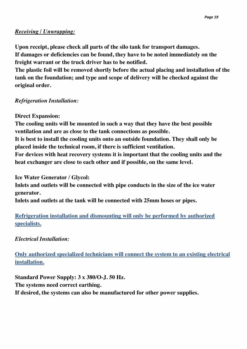
Receiving / Unwrapping: Upon receipt, please check all parts of the silo tank for transport damages. If damages or deficiencies can be found, they have to be noted immediately on the freight warrant or the truck driver has to be notified. The plastic foil will be removed shortly before the actual placing and installation of the tank on the foundation; and type and scope of delivery will be checked against the original order. Refrigeration Installation: Direct Expansion: The cooling units will be mounted in such a way that they have the best possible ventilation and are as close to the tank connections as possible. It is best to install the cooling units onto an outside foundation. They shall only be placed inside the technical room, if there is sufficient ventilation. For devices with heat recovery systems it is important that the cooling units and the heat exchanger are close to each other and if possible, on the same level. Ice Water Generator / Glycol: Inlets and outlets will be connected with pipe conducts in the size of the ice water generator. Inlets and outlets at the tank will be connected with 25mm hoses or pipes. Refrigeration installation and dismounting will only be performed by authorized specialists. Electrical Installation: Only authorized specialized technicians will connect the system to an existing electrical installation. Standard Power Supply: 3 x 380/O-J. 50 Hz. The systems need correct earthing. If desired, the systems can also be manufactured for other power supplies.

Page 20
Maintenance: If the tank comes with glycol-cooling through the outlet pipe, the amount of glycol has to be checked every three months. Annual Service: Tank: Dismount sprinkler and check for wear and tear; clean nozzles. Exchange ground bearing for the agitator. Check agitator; sound and leakage. Check manhole and gasket; clean / exchange. Visually check tank and outlet.
Check glycol cooling at outlet pipe: Pump, glycol and tightness. Check of safety and special accessories. Washing Unit:
Exchange dosage hoses of pumps. Clean filters of water valves. Check volume of water and dosage of detergents. Check rinsing pump and drainage pump. Check tightness. Check hose connections.
Check electrical joints and connections. Check course of programme, including washing temperature. Cooling: Check that optimal cooling is provided. Check function of thermostat; start / stop. Check breaks of agitator and duration. Check manual cooling function.
*** Please note the guiding rules and regulations for annual service and maintenance etc.

Page 21
Special Accessories and Equipment:
Full-indicator: mounted on top of the tank.
Tank guard controls the functional processes of the tank.
Sample extractor: mounted on manhole.
Safety ladder for silo tanks.

Page 22
N N 1 3 L1-L2-L2-N-E
1
2 8
9 10
2
KP1
(3xFuse) L1-L2-L2-N-E
Entry L1-L2-L3-N-E
Cooling unit
Circuit Diagram for 1 Cooling Unit. Danfoss HGZ

Page 23
N N 1 3 L1-L2-L2-N-E 1 2
8
9
10 2
10
9
KP1 1 N
2 20 19
8
(3xFuse) L1-L2-L2-N-E
Entry L1-L2-L3-N-E
Cooling unit 1
Cooling unit 2 Slave
Change in connections
Circuit Diagram for 2 Cooling Units. Danfoss HGZ Delayed start: 4 sec. for cooling unit 2

Page 24
Connection of Agitator
Gear motor: Type SK2282 AFBHVL-90S/4
Gear motor R1C245 NSB
N N 1
E N
T1-T2-T3 3 x 400 v¨ 50 Hz.
E
**Important** Agitator has to run clock-wise.
1 x 230 v¨ 50 Hz.

Page 25
Installing / Connecting 10/20 kW Heater
Washing unit uniUni. Vaskeautomat. tomat.
Heater mounted onto silo tank
Pipe / Hose connection
Safety
N 12
Separate entry 3 x 400 v¨ 50 Hz.
10.000 40.000 L. with soft starter
10.000 – 40000 L. with soft-starter

Page 26

Page 27
N 1
Circuit Diagram for Danfoss HGZ units