Embed Size (px)
Citation preview
TECHNICAL DESCRIPTION
PULSE WIDTH MODULATED4-QUADRANT SERVO-CONTROLLER
TYPE
TRA

IMPORTANT!
* It is of vital importance that you read the technical description before starting-up
* Protect the unit from aggressive and electrically conductive media. They could cause malfunction and/or destroy the unit!
* Do not touch any life parts. Danger to life!
* Installation, connection and starting-up may only be carried out by an expert subject to all relevant safety regulations.
* Assured properties and functions of the unit are only guaranteed when expertly handled.
* Tamperings and modifications that have not been expressly authorized by us, as well as any non-authorized use result in the exclusion of any guarantee and liability.
* Basis for any legal business with us are our "Allgemeine Gesch‰ftsbedingungen " (General Terms of Business).
* All documentations, drawings, diagrams etc. are subject to copyright terms. Any use, duplication, forwarding, processing and alteration without our explicit consent is prohibited.

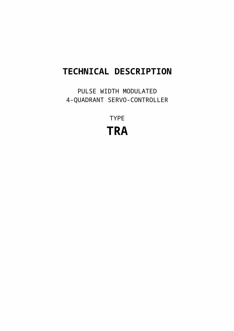
Table of Contents
Page
1. Technical Description 41.1 General introduction 41.2 Model overview 41.3 Technical data 51.4 Control principle 61.5 Description of function 71.6 Block diagram 91.7 Overview setting possibilities / displays 101.8 Front view 11
2. Connecting the Unit 122.1 Plug wiring 122.2 Explanation of plug wiring 132.3 Proper polarity of motor and tachometer 142.4 Input monitoring circuit 152.5 Connection diagram (proposal) 162.6 Running of wires 17
3. Starting-up 173.1 Presettings 173.2 Setting of pulse and effective current 183.3 Tachometer adaptation 183.4 EMK and IxR compensation 183.5 Offset-rectification 19
4. Optimizing the control behaviour 194.1 Amplification of alternating voltage 194.2 Amplification of direct voltage 194.3 Tachometer screening 194.4 Integral part of speed controller 20
Appendix: Line-up diagramsBasic printed circuit board TRASpeed control module TRA-D
1. Technical Description
1.1 General Introduction
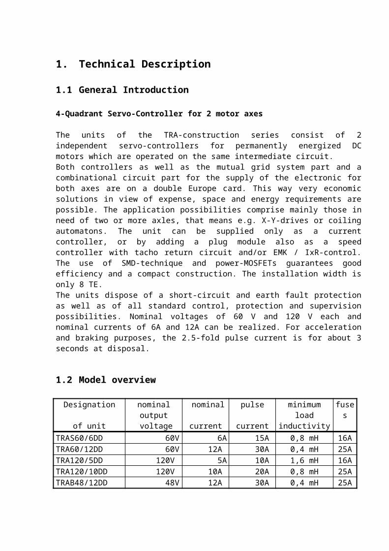
4-Quadrant Servo-Controller for 2 motor axes
The units of the TRA-construction series consist of 2 independent servo-controllers for permanently energized DC motors which are operated on the same intermediate circuit.Both controllers as well as the mutual grid system part and a combinational circuit part for the supply of the electronic for both axes are on a double Europe card. This way very economic solutions in view of expense, space and energy requirements are possible. The application possibilities comprise mainly those in need of two or more axles, that means e.g. X-Y-drives or coiling automatons. The unit can be supplied only as a current controller, or by adding a plug module also as a speed controller with tacho return circuit and/or EMK / IxR-control. The use of SMD-technique and power-MOSFETs guarantees good efficiency and a compact construction. The installation width is only 8 TE.The units dispose of a short-circuit and earth fault protection as well as of all standard control, protection and supervision possibilities. Nominal voltages of 60 V and 120 V each and nominal currents of 6A and 12A can be realized. For acceleration and braking purposes, the 2.5-fold pulse current is for about 3 seconds at disposal.
1.2 Model overview
Designation nominal output nominal pulse minimum load fusesof unit voltage current current inductivity
TRAS60/6DD 60V 6A 15A 0,8 mH 16ATRA60/12DD 60V 12A 30A 0,4 mH 25ATRA120/5DD 120V 5A 10A 1,6 mH 16ATRA120/10DD 120V 10A 20A 0,8 mH 25ATRAB48/12DD 48V 12A 30A 0,4 mH 25A
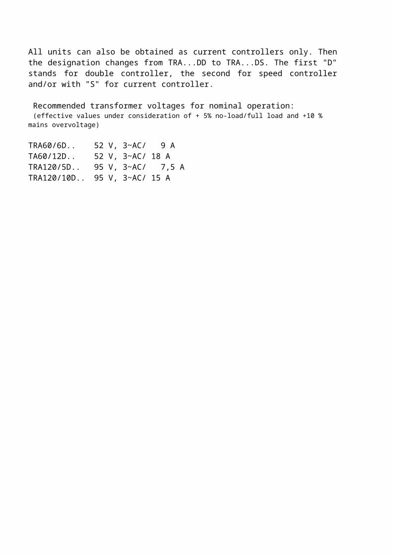
All units can also be obtained as current controllers only. Then the designation changes from TRA...DD to TRA...DS. The first "D" stands for double controller, the second for speed controller and/or with "S" for current controller.
Recommended transformer voltages for nominal operation: (effective values under consideration of + 5% no-load/full load and +10 % mains overvoltage)
TRA60/6D.. 52 V, 3~AC/ 9 ATA60/12D.. 52 V, 3~AC/ 18 ATRA120/5D.. 95 V, 3~AC/ 7,5 ATRA120/10D.. 95 V, 3~AC/ 15 A
1.3 Technical Data
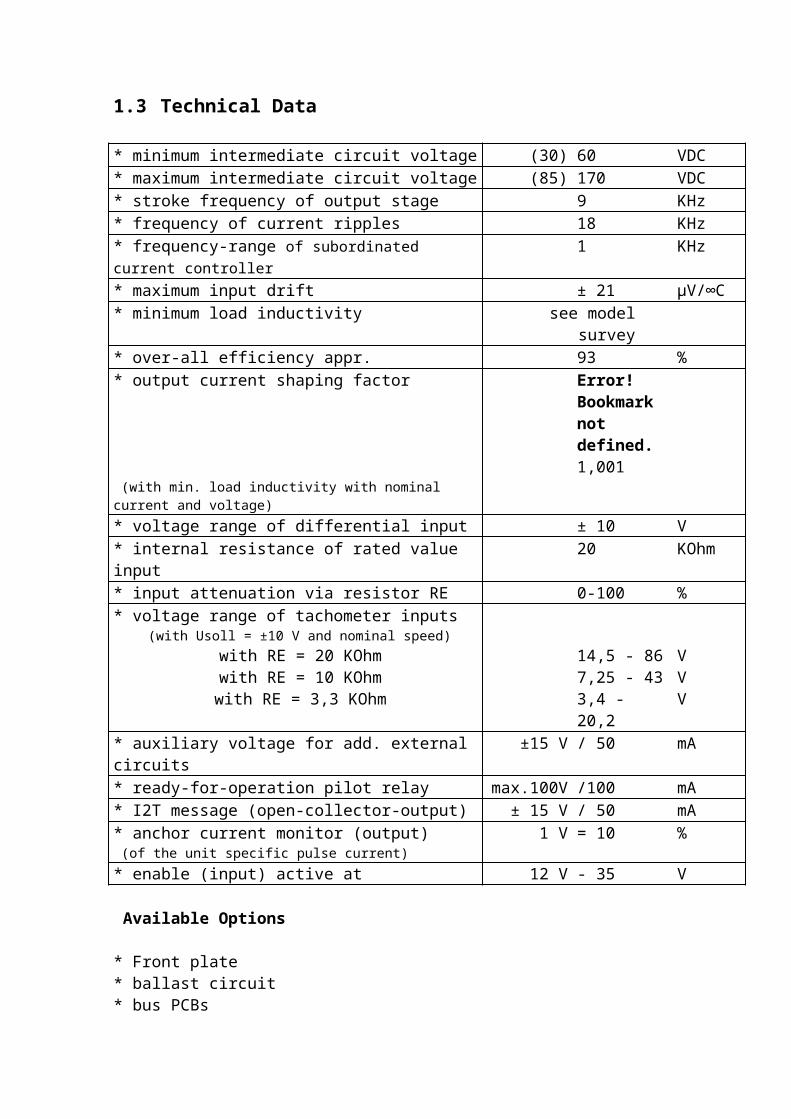
* minimum intermediate circuit voltage (30) 60 VDC* maximum intermediate circuit voltage (85) 170 VDC* stroke frequency of output stage 9 KHz* frequency of current ripples 18 KHz* frequency-range of subordinated current controller 1 KHz* maximum input drift ± 21 µV/∞C* minimum load inductivity see model survey* over-all efficiency appr. 93 %* output current shaping factor Error!
Bookmark not defined. 1,001
(with min. load inductivity with nominal current and voltage)* voltage range of differential input ± 10 V* internal resistance of rated value input 20 KOhm* input attenuation via resistor RE 0-100 %* voltage range of tachometer inputs
(with Usoll = ±10 V and nominal speed) with RE = 20 KOhm 14,5 - 86 V with RE = 10 KOhm 7,25 - 43 V with RE = 3,3 KOhm 3,4 - 20,2 V
* auxiliary voltage for add. external circuits ±15 V / 50 mA* ready-for-operation pilot relay max.100V /100 mA* I2T message (open-collector-output) ± 15 V / 50 mA* anchor current monitor (output) 1 V = 10 % (of the unit specific pulse current)* enable (input) active at 12 V - 35 V
Available Options
* Front plate * ballast circuit* bus PCBs * current control
1.4 Control Principle
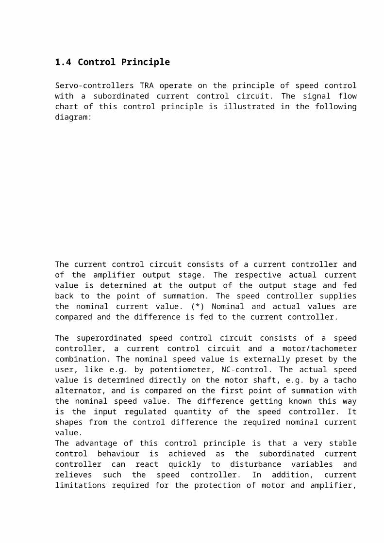
Servo-controllers TRA operate on the principle of speed control with a subordinated current control circuit. The signal flow chart of this control principle is illustrated in the following diagram:
The current control circuit consists of a current controller and of the amplifier output stage. The respective actual current value is determined at the output of the output stage and fed back to the point of summation. The speed controller supplies the nominal current value. (*) Nominal and actual values are compared and the difference is fed to the current controller.
The superordinated speed control circuit consists of a speed controller, a current control circuit and a motor/tachometer combination. The nominal speed value is externally preset by the user, like e.g. by potentiometer, NC-control. The actual speed value is determined directly on the motor shaft, e.g. by a tacho alternator, and is compared on the first point of summation with the nominal speed value. The difference getting known this way is the input regulated quantity of the speed controller. It shapes from the control difference the required nominal current value.The advantage of this control principle is that a very stable control behaviour is achieved as the subordinated current controller can react quickly to disturbance variables and relieves such the speed controller. In addition, current limitations required for the protection of motor and amplifier, can be realized in a simple way only by limiting the output voltage of the speed controller (nominal current value).
(*) In some applications a superordinated position control circuit already takes care of the speed control. Therefore the TRA can be modified in such a way that it works only as current controller - please consult our technicians in case of demand.
1.5 Description of Functions with Block Diagram
a. Voltage supply
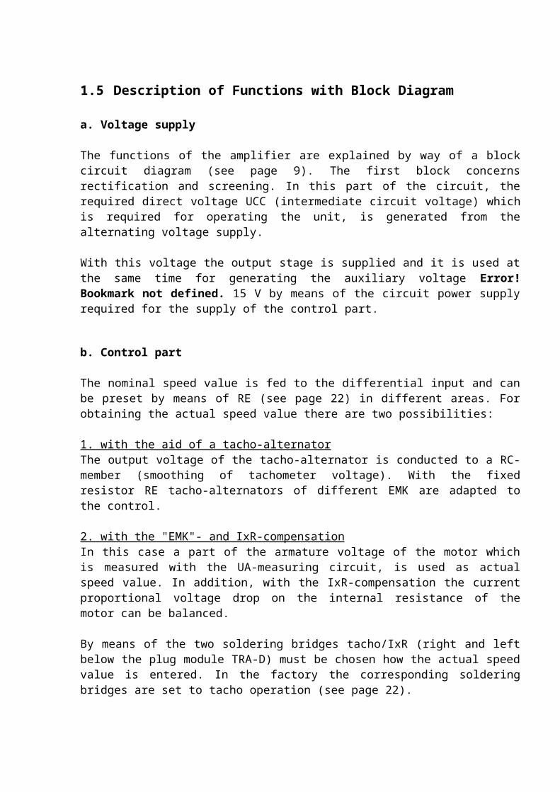
The functions of the amplifier are explained by way of a block circuit diagram (see page 9). The first block concerns rectification and screening. In this part of the circuit, the required direct voltage UCC (intermediate circuit voltage) which is required for operating the unit, is generated from the alternating voltage supply.
With this voltage the output stage is supplied and it is used at the same time for generating the auxiliary voltage Error! Bookmark not defined. 15 V by means of the circuit power supply required for the supply of the control part.
b. Control part
The nominal speed value is fed to the differential input and can be preset by means of RE (see page 22) in different areas. For obtaining the actual speed value there are two possibilities:
1. with the aid of a tacho-alternatorThe output voltage of the tacho-alternator is conducted to a RC-member (smoothing of tachometer voltage). With the fixed resistor RE tacho-alternators of different EMK are adapted to the control.
2. with the "EMK"- and IxR-compensationIn this case a part of the armature voltage of the motor which is measured with the UA-measuring circuit, is used as actual speed value. In addition, with the IxR-compensation the current proportional voltage drop on the internal resistance of the motor can be balanced.
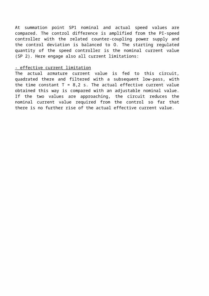
By means of the two soldering bridges tacho/IxR (right and left below the plug module TRA-D) must be chosen how the actual speed value is entered. In the factory the corresponding soldering bridges are set to tacho operation (see page 22).At summation point SP1 nominal and actual speed values are compared. The control difference is amplified from the PI-speed controller with the related counter-coupling power supply and the control deviation is balanced to O. The starting regulated quantity of the speed controller is the nominal current value (SP 2). Here engage also all current limitations:
- effective current limitationThe actual armature current value is fed to this circuit, quadrated there and filtered with a subsequent low-pass, with the time constant T = 8,2 s. The actual effective current value obtained this way is compared with an adjustable nominal value. If the two values are approaching, the circuit reduces the nominal current value required from the control so far that there is no further rise of the actual effective current value.

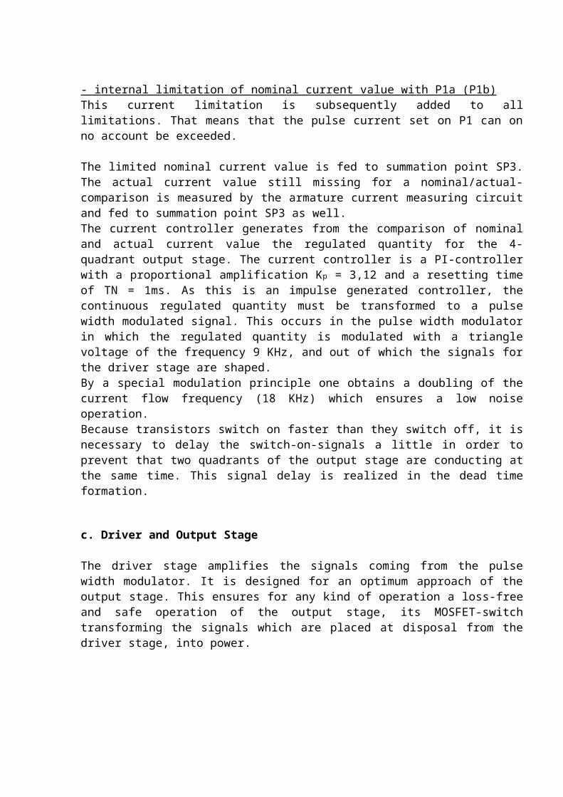
- internal limitation of nominal current value with P1a (P1b)This current limitation is subsequently added to all limitations. That means that the pulse current set on P1 can on no account be exceeded.
The limited nominal current value is fed to summation point SP3. The actual current value still missing for a nominal/actual-comparison is measured by the armature current measuring circuit and fed to summation point SP3 as well. The current controller generates from the comparison of nominal and actual current value the regulated quantity for the 4-quadrant output stage. The current controller is a PI-controller with a proportional amplification Kp = 3,12 and a resetting time of TN = 1ms. As this is an impulse generated controller, the continuous regulated quantity must be transformed to a pulse width modulated signal. This occurs in the pulse width modulator in which the regulated quantity is modulated with a triangle voltage of the frequency 9 KHz, and out of which the signals for the driver stage are shaped.By a special modulation principle one obtains a doubling of the current flow frequency (18 KHz) which ensures a low noise operation.Because transistors switch on faster than they switch off, it is necessary to delay the switch-on-signals a little in order to prevent that two quadrants of the output stage are conducting at the same time. This signal delay is realized in the dead time formation.
c. Driver and Output Stage
The driver stage amplifies the signals coming from the pulse width modulator. It is designed for an optimum approach of the output stage. This ensures for any kind of operation a loss-free and safe operation of the output stage, its MOSFET-switch transforming the signals which are placed at disposal from the driver stage, into power.
1.6 Blockdiagram TRA

1.7 Survey of Displays and Setting Possibilities
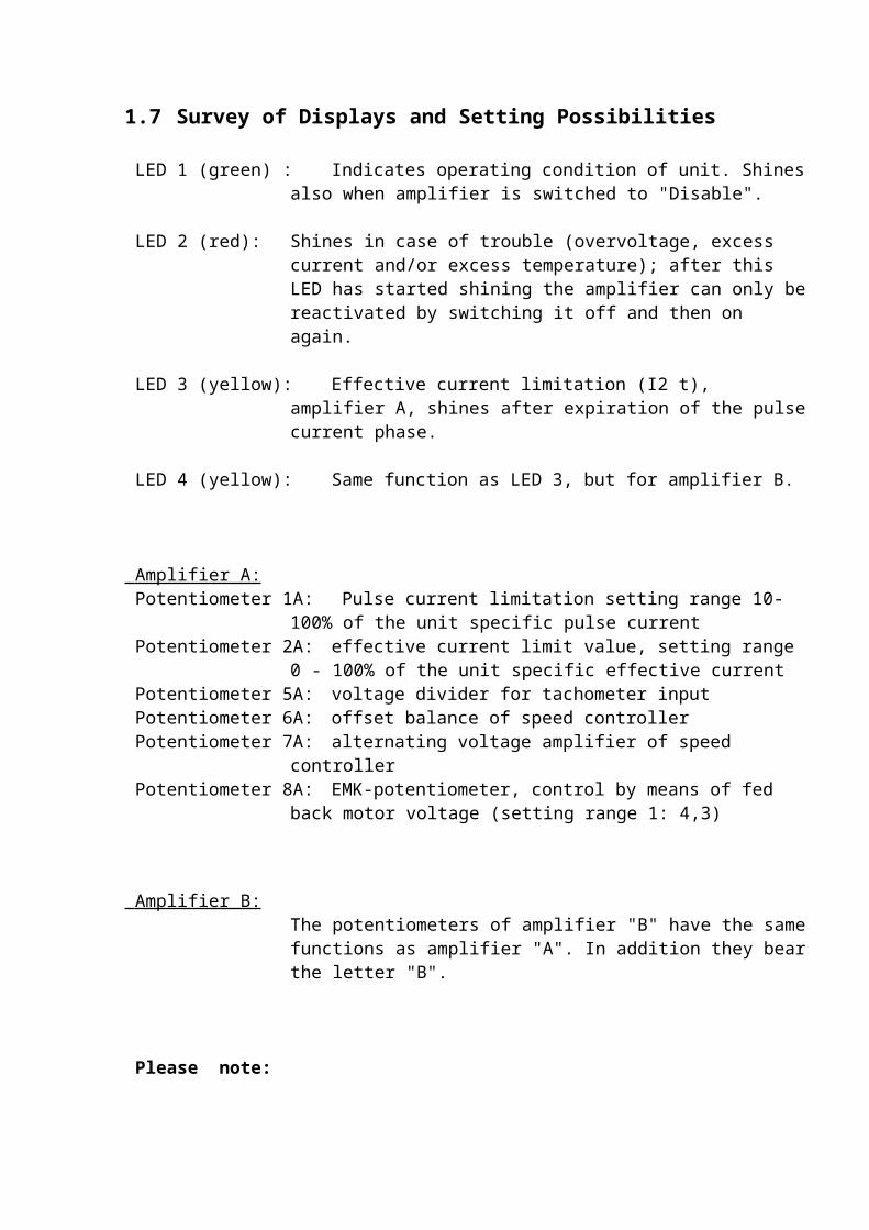
LED 1 (green) : Indicates operating condition of unit. Shines also when amplifier is switched to "Disable".
LED 2 (red): Shines in case of trouble (overvoltage, excess current and/or excess temperature); after this LED has started shining the amplifier can only be reactivated by switching it off and then on again.
LED 3 (yellow): Effective current limitation (I2 t), amplifier A, shines after
expiration of the pulse current phase.
LED 4 (yellow): Same function as LED 3, but for amplifier B.
Amplifier A: Potentiometer 1A: Pulse current limitation setting range 10-100% of the unit specific
pulse current Potentiometer 2A: effective current limit value, setting range 0 - 100% of the unit
specific effective current Potentiometer 5A: voltage divider for tachometer input Potentiometer 6A: offset balance of speed controller Potentiometer 7A: alternating voltage amplifier of speed controller Potentiometer 8A: EMK-potentiometer, control by means of fed back motor voltage
(setting range 1: 4,3)
Amplifier B: The potentiometers of amplifier "B" have the same functions as amplifier "A". In addition they bear the letter "B".
Please note: The potentiometers P5A-P8A and P5B-P8B are on the plug module "TRA-D" (speed control). When the unit is used as a current controller these potentiometers do not exist.
1.8 Front View
2. Connecting the Unit
2.1 Plug Wiring
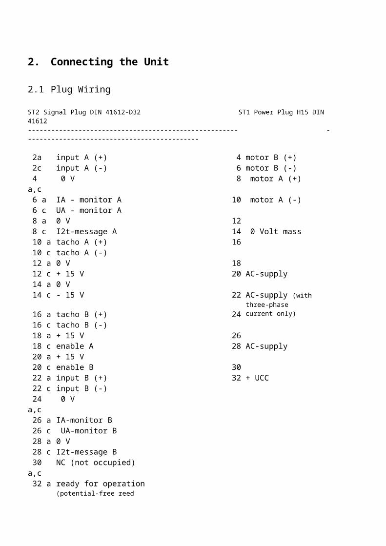
ST2 Signal Plug DIN 41612-D32 ST1 Power Plug H15 DIN 41612------------------------------------------------------ ---------------------------------------------
2a input A (+) 4 motor B (+) 2c input A (-) 6 motor B (-) 4 a,c 0 V 8 motor A (+) 6 a IA - monitor A 10 motor A (-) 6 c UA - monitor A 8 a 0 V 12 8 c I2t-message A 14 0 Volt mass 10 a tacho A (+) 16 10 c tacho A (-) 12 a 0 V 18 12 c + 15 V 20 AC-supply 14 a 0 V 14 c - 15 V 22 AC-supply (with three-phase 16 a tacho B (+) 24 current only) 16 c tacho B (-) 18 a + 15 V 26 18 c enable A 28 AC-supply 20 a + 15 V 20 c enable B 30 22 a input B (+) 32 + UCC 22 c input B (-) 24 a,c 0 V 26 a IA-monitor B 26 c UA-monitor B 28 a 0 V 28 c I2t-message B 30 a,c NC (not occupied) 32 a ready for operation (potential-
free reed contact) 32c ready for operation (for both
axles together)
2.2. Explanation of Plug Wiring
References for amplifier B are in square brackets.
Mass: = 0 V reference potential.
ST2 Signal Plug D32
Auxiliary voltage Error! Bookmark not defined.15 V (12 c - 14 c)At clamp 12c an auxiliary voltage of + 15 V and on clamp 14 c of -15 V for external consumers with a power input of max. 50 mA are at disposal.
Nominal Value Input (2a - 2c) [22a - 22 c]Input of differential amplifiers for presetting the nominal speed value. The maximum differential voltage may be Ò 10 V. Clamp 2a [22a] acts positively towards clamp 2c [22c].
Tacho Input (10a - 10c) [16a - 16c])Input for connecting DC-tacho alternators for return message of speed. For nominal speed with a nominal value of 10 V the tacho voltage should be at least 3,5 V and not more than 86 V. The ranges must be determined with the fixed resistor RE (see page 18).
Enable (Release of Output Stage) (18c) [20c]For standard operation this connection must be connected with a voltage between 12 and 35 V. With a voltage below 4 V and with an open input this output stage is "disabled" and the motor is not energized. The range between 4 V and 12 V is not defined.
Anchor Current Monitor (6a) [26a]These outputs dispose of a current proportional analogous signal which can be externally evaluated. The maximum voltage with a unit specific pulse current is Ò 10 V.
Anchor Voltage Monitor 6 c [26c]These outputs supply a voltage proportional to the anchor voltage of the motor. The 60 V-units have a monitor with standard 6 V at 60 V EMK. The monitor of 120V-units supplies 10 V at 120 V EMK.
Relay contact "Ready for Operation" (32a - 32c)Potential-free relay contact indicating that the unit is ready for operation. This contact is closed when the unit is ready for operation and is not influenced by the enable-function. In case of trouble (LED 2 shines), the contact is open. This function exists only one time, that means it is controlled by both axles together.

ST1 Power Plug H15
Motor connections (8 and 10) [4 and 6]These are the output clamps of the output stages to which the motors are connected.
Trafo Connections (18/20 - 22/24 - 26/28)The secondary connections of the transformer are connected to these contacts. These connections must be secured externally. When using a single-phase transformer, connections 18/20 and 26/28 must be used. Attention must be paid that the transformer connections are connected to the respective two contacts.When using an extremely low-resistance transformer (e.g. with parallel connection of several axles) a cutting-in current limiter might be necessary in order not the destroy the rectifier diodes.
Connections UCC (30,32) O Volt (12,14,16)These connections are either used for an external ballast circuit (available as option) or if a direct voltage supply is requested.
2.3 Proper Polarity of Motor and Tachometer
If one turns - while the unit is switched off - the motor shaft by hand in the direction defined as positive, then on clamps 8 [4] a positive voltage must be measurable compared with clamps 10 [6]. Further the tacho voltage on clamp 10 a [16a] must be positive compared with clamp 10 c [16c]. If the polarity of motor or tachometer is not correct, the corresponding connection lines must be interchanged.
2.4 Input Monitoring Circuit

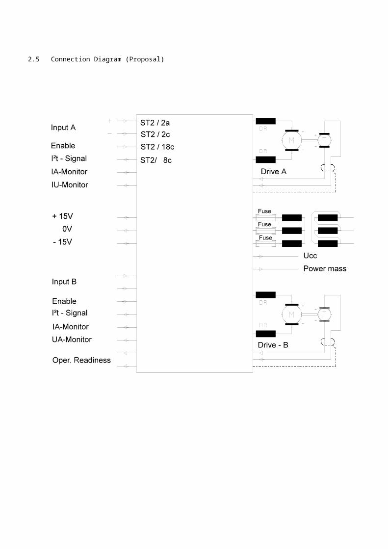
2.5 Connection Diagram (Proposal)

2.6 Running of Wires
In order to prevent function trouble or subsequent damage in case of mass or ground leaks, motor housing and the cores of possibly existing external storage coils must be ground lowly resistive against the power mass (ST1/12,14,16).When not observing this regulation, there can be heavy damage on all amplifier construction groups and on the control in case of mass leaks on the output, if this is operating on earth potential.
Control and servo-amplifier must lie on the same potential (mostly earth potential). If the control (e.g. a simple battery box) is not self-ground, the screening of the control cable for the potential balance may be used; the screen is then connected to the servo-amplifier and to the control box. With ground control, the screen of the control line must only be connected to the control and not to the amplifier.
The lines of an input (+ and -) must both be conducted in the same cable right up to the control. Referring one of the two control input lines to the 0 V potential on the servo-amplifier, nullifies the advantages of the differential input and can lead to trouble. The screen of the tacho-line must only be ground to the amplifier. The tacho-alternator itself must only be connected or ground to the provided input clamps and nowhere else.
Long motor lines must consist of a 2-wired separate cable for each motor. For special requirements concerning immunity from interference, a screened cable can be used; the screen must be connected to the minus pole of the DC-intermediate circuit. If the motor housing has no further earth connection, the screen can be used instead of a separate earth circuit. The result is a construction with an especially low interference rate.
3. Starting up
3.1 Presetting
Please check the wiring carefully and compare all connections according to the plug wiring on page 12. All units have of course been tested and have been preset with the nominal data before leaving our works.If you might not be able to totally exclude wiring faults, we recommend to proceed as following in order to prevent damage on motor and machine:
* Set rated value input to 0, or short-circuit the input* set tacho poti P5A [P5B] to left-hand stop* set amplifier poti P7A [P7B] to left-hand-stop* pulse-current poti P1A [P1B] to about 1/3 from left-hand stop* effective current poti P2A [P2B] to about 1/3 from left-hand stop
Are the soldering bridges set to the requested mode of operation? (see page 22). When you now switch on the motor it must develop a holding torque and may drift just a little. If the motor runs off uncontrolled please switch it off immediately and check again the tacho-circuit in view of wrong polarity, short-circuit or line interruption.If now small rated values are preset, the motor must follow them.
3.2 Setting of Pulse and Effective Current
For a precise setting of the pulse current, either the nominal value O V can be preset and the motor manually turned out of the zero position, or the motor blocks and a constant nominal value can be preset. Then the potentiometer P1A [P1B] must be set to the requested pulse current. If the I2t-current limit actuates, the Enable-input must be opened for about 20 seconds for the unit to regenerate; after closing it again, the setting can be continued. After the expiration of the pulse current phase, the current is automatically reduced to the effective current, which can be set on P2A [P2B]. When setting the P2A [P2B] always proceed in portions and without hesitation. After a short time of adaptation in which the current is either O or IIMP, the new permanent current is flowing.
Please note:For measuring the set current, the motor can be replaced by an ammeter with suitable measuring range. The required minimum load inductivity (see table page 4) must however be ensured, if necessary by coils.

3.3 Tachometer Adaptation
In the factory the units are equipped with a tachometer supplying 6 V / 1000 r.p.m. and adjusted to a motor speed of 3.000 r.p.m.For setting the maximum speed, a nominal value of 10 V, or a certain percentage of this, is put on the nominal value input. With the tacho poti P5A [P5B] then the requested final speed, or the same percentage like with the nominal value is adjusted. If the speed cannot be adjusted in the requested range this way, then another tacho voltage range must be selected by changing the resistor RE. The line-up place of the RE can be found on page 22.
Tacho voltage range values for RE 14,5 - 86 V 20 KOhm 7,25 - 43 V 10 KOhm 3,4 - 20 V 4,7 KOhm
If the speed is too high, RE must be reduced and reversed. From the manufacturer a value of 20 KOhm has been soldered into the RE.
3.4 EMK and IxR-Compensation
If there is no tacho-alternator for speed control at disposal, then the soldering bridge "Tacho/EMK" (see page 22) must be resoldered to "EMK" as shown in the diagram. In this case it is possible to set the requested maximum speed with a nominal value presetting of 10 V with the EMK-potentiometer P8A [P8B].If additionally an IxR-compensation is requested, then this can be carried out by soldering-in a respective resistance RxA [RxB] (see page 22). The IxR-compensation effects an increase of the output voltage, which compensates proportionally to the current input the voltage drop on the internal motor resistance and thus counteracts to the speed drop with increasing load. The size of the resistance RX to be soldered in depends on the internal resistance of the motor, but also on the ratio of nominal motor voltage and nominal amplifier voltage.For an optimum setting of the IxR-compensation start/stop-impulses are preset and the braking behaviour of the motor is observed. The correct value for RxA [RxB] is easiest determined by connecting a resistance decade which is clamped to the RX-connections. One starts with a low-resistance setting, e.g. 1 KÍ and increases the resistance value for so long until the requested step function response is achieved. When braking, the motor should reach the new nominal speed value after overshooting once or twice. If no overshooting can be detected, RX must be increased. If the overshooting lasts too long or is too strong, RX must be reduced.
3.5 Offset-Rectification
After all preceding settings have been carried out, there is still the offset-rectification to be performed. For this purpose, again the rated value 0 Volt is preset and any possible drifting off of the motor shaft is prevented with P2.
For a more precise setting of the offset, the tachometer voltage can be measured on clamps 10a [16a] and 10c [16c] with a voltmeter (switch to smallest measuring range) and balanced to 0 Volt.

4. Optimizing the Control Behaviour
4.1 Amplification of Alternating Voltage
In most applications an optimizing is limited to setting the alternating voltage amplifier (gain) on potentiometer P7A [P7B]. For this purpose couple the motor to the load and preset a rated value of 0 V. Turn potentiometer P7A [P7B] to the right until the oscillation starts and then turn immediately to the left until you find the point where it stops again.
4.2 Amplification of Direct Voltage
Especially with a superordinated position control circuit, a precisely defined static rigidity is often requested. For changing this rigidity, the resistance RP-A [RP-B] (appr. 330 Ohm) is provided (see page 22). The rigidity lessens with increasing resistance. The static rigidity must not be confused with the dynamic rigidity which can be set on P7A [P7B] (amplification of alternating voltage).
4.3 Tachometer Screening
For filtering the tachometer signal, the capacitor CT-A [CT-B] has been provided with appr. 47 n F (see page 22). This capacitor must additionally limit the control range in such a way that there is no oscillation by torsion resonances. If the motor causes howling sounds which cannot be removed by means of the amplifier potentiometer P7, then such an oscillation by torsion resonance is the case. For its suppression the capacitor CT must be increased stepwise until the motor is running quietly. Increasing it above that point, unnecessarily worsens the dynamic control behaviour (overshooting).
4.4 Integral Part of Speed Controller
For the integral part of the speed controller, the capacitor CI-A [CI-B] with appr. 100 nF is competent (see page 22).The requirements in view of the dynamic of the amplifiers clearly differ when operating them as speed controllers from those required when there is a superordinated position controller at hand.
In the first case, the rigidity must be produced by the speed controller, which is why its integral amplification must be as big as possible (CI must be small), whereby a brief overshooting is mostly permitted. Contrary to this, in an operation with a superordinated position controller the rigidity is produced by the controller. The important factor here is the biggest possible bandwidth of the servo-amplifier, whereby the integral amplification can be much lower than in the first case. The capacitor CI must be enlarged for this. The overshooting of the amplifier without position control gets less this way, the braking time until standstill of the motor takes, however, a little longer.

Basic Printed Circuit Board PC-TRA
Speed Control Module TRA-D


![Single axis devices - Compumotor Automation Europe [EME] Robert-Bosch-Strasse 22 77656 Offenburg (Germany) ... 2.1 Device assignment This manual applies to the following devices:](https://img.pdfslide.net/doc/110x75/5ae9d7997f8b9ae5318b9c2d/single-axis-devices-automation-europe-eme-robert-bosch-strasse-22-77656-offenburg.jpg)