Embed Size (px)
Citation preview
Technical Document
for the
CB 016N6 Driver Card
- 2 -
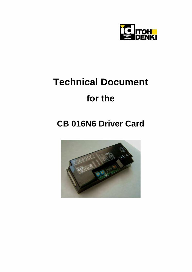
Contents Page 1 Introduction 3 2 New functions 3 3 Dimensions 3 4 I/O Interface 4 5 Connectors 4-5 6 Switches 5-6 7 Potentiometers 7 8 LEDs and Error Indications 7-10 9 Electrical specifications 10 10 Environmental concerns 11 11 Precautions to ensure the best performance 11
Revision index:
rev. date pos. name Procedure / modification 000 6/22/2009 New document released

- 3 -
1. Introduction The CB 016S6 driver card is a new driver card for brushless dc motorized roller to replace the current CB 016N3 driver card. The design concept is to keep the basic functions of the current CB 016N3 driver card. And more importantly the CB 016N3 is designed to be lead free to comply with RoHS directive. The CB 016N6 driver card is applicable to PM486 (or 500) FS, FE, FP series Power Moller. Also available are the following models depending on the type of signal and with or without brake option: CB 016P6 for standard motor, PNP signal input and output CB 016S6 for standard motor, NPN signal input and PNP signal output CB 016BN6 for built-in brake motor, NPN signal input and output CB 016BP6 for built-in brake motor, PNP signal input and output CB 016BS6 for built-in brake motor, NPN signal input and PNP signal output
2. Features RoHS and EMC conformity. Motor pulse signal output (2 pulses / rotation) – NPN open collector output. Selections switch for manual or automatic recovery of thermal overload device or shortage voltage (to protect
micro processor against voltage lower than 15V). Adjustable acceleration and deceleration time (up to 2.5 sec) by integral pot. Selection switch for manual or automatic recovery of the thermal overload device Integral 10 index rotary switch along with a dip switch to select 20 different fixed speeds. 20 step fixed speed can also be obtained by varying external voltage input between 0 and 10 V by selecting
external speed variation mode Switch to select the timing of error signal discharge; discharge in normal or discharge in abnormal status. Forcibly stops the motor if motor blocking or thermal overload error lasts for 4 seconds or over to protect the
motor from overheating. Allowable reversing motor while motor is running. Three (3) LEDs (green, red and orange) to identify the type of error and number of error occurrence
3. Dimensions

- 4 -
4. I/O Interface
5. Connectors
CN1 Power Connector 2P Driver side
WAGO #734-162 Power cable side WAGO #734-102
1 Power(+24V) +24V 2 Power(0V(GND)) 0V
24V
ERR_OUT
100Ω
+24V 1
0V 2
CN1
5
4
3
2
1CN2
ERR
Vin
PLS
Vinput
12V
RUN
DIR
9
5V
5V
21
3
54
6
SW2
21
3
54
6SW4
12V
11 10
100Ω
R75
ERR
ERR
DIR-IN

- 5 -
CN2 Control Connector 5P Driver side
WAGO #733-365 Control cable side WAGO #733-105
1 Run / Stop Run with NPN 0V or PNP24V input 2 Direction Reversing from direction with SW1-3 setting 3 External analog voltage
input for speed variation When SW1-2 is ON, varying external voltage input (0-10V) can vary the motor speed
4 Error signal output SW1-4 switching for signal discharge in normal or abnormal status (O.C output 24V,25mA or less)
5 Motor pulse output 2 pulses / motor rotation, open collector output NPN signal only – max. 24V, 25mA or less
CN 3 Motor Connector 9P for standard motor (10P for brake motor)
Driver side JST #S9B-XH-A(9P) JST #S10B-XH-A(10P)
Motor cablse side JST #XHP-9 or #XHP-10 (Afixed to motor cable)
1 GND (grey) 2 +12V(blue) 3 Motor phase(red) 4 Motor phase(white) 5 Motor phase(black) 6 Hall IC U (violet) 7 Hall IC V (orange) 8 Hall IC W (green) 9 Thermister (Lt blue)
10 Brake(yellow)
Socket terminal SXH-001P-P0.6 (JST) Wire AWG 28~22 Except motor phase AWG24~22
6. Switches
SW Function ON setting OFF setting Initial setting N/P/BN/BP
Initial setting S/BS
1 Selection of manual or automatic thermal device recovery
Manual Automatic *1 ON ON
2 Selection of internal or external speed change
External speed variation (0-10V input)
Internal speed variation OFF OFF
3 Selection of motor turning dierction; CW or CCW
in accordance with the combination of motor and CN2-2 *2 OFF OFF
4 Selection of error signal discharge mode
Discharge on normal Discharge on abnormal OFF ON
5 Speed range setting High range Low range ON ON * 1 Motor restarts 1 minute after the thermal device is cooled down.
* 2 Motor turning direction according to combination SW1-3
FS/FP FE/GE
ON OFF ON OFF CN2-2 ON CW CCW CCW CW CN2-2 OFF CCW CW CW CCW
viewed from the motor power cable side The motor turning direction cannot be changed while it is turning

- 6 -
* 3 20 different fixed speeds with 2 stage gearing Power Moller (48.6mm diameter)
Set the sip switch 1-5 L (off) for setting low range speed and H (on) for high range speed. Note: rotary is set to 9 as initial setting.
Rotary switch
Low range speed (m/min) +/-3%
Rotary switch
High range speed (m/min) +/-3%
0 7.5 0 32.5 1 10.0 1 35.0 2 12.5 2 37.5 3 15.0 3 40.0 4 17.5 4 45.0 5 20.0 5 47.5 6 22.5 6 50.0 7 25.0 7 52.5 8 27.5 8 55.0 9 30.0 9 60.0
Speed of 50mm diameter roller is about 3% faster than the figures in the table. Note: Those speed ranges in the table can be obtained only when 60m/min motor is used. In case of operating motor slower than 60m/min., any dip switch setting won’t make its speed faster than its own maximum speed. The below 20 step fixed speed can also be obtained by varying external analog voltage input between 0 and 10 V by selecting external speed variation mode (SW2 ON)
Input voltage Speed (m/min) +/-3%
Input voltage Speed (m/min) +/-3%
0.05-0.45V 7.5 5.05-5.45V 32.5 0.55-0.95V 10.0 5.55-5.95V 35.0 1.05-1.45V 12.5 6.05-6.45V 37.5 1.55-1.95V 15.0 6.55-6.95V 40.0 2.05-2.45V 17.5 7.05-7.45V 45.0 2.55-2.95V 20.0 7.55-7.95V 47.5 3.05-3.45V 22.5 8.05-8.45V 50.0 3.55-3.95V 25.0 8.55-8.95V 52.5 4.05-4.45V 27.5 9.05-9.45V 55.0 4.55-4.95V 30.0 9.55-9.95V 60.0
Note: Those speed ranges in the table can be obtained only when 60m/min motor is used. In case of operating other speed motor, once it reached to its maximum speed, any voltage won’t increase the speed faster than its maximum speed. CB 016S6 driver card has stable speed and constant torque features, thus one fastest motor (FE-60 or FP-55) can basically cover the whole speed range.
Output signal selection Upper PNP output
SW4 Bottom NPN output
Input signal selection Left NPN input
SW2 Right PNP input

- 7 -
7. Potentiometers VR 1 – Acceleration time adjustment (0-2.5 sec) Acceleration time from the RUN signal input can be adjusted between 0 and 2.5 sec VR 2 – Deceleration time adjustment (0-2.5 sec) Deceleration time from the stop signal input can be adjusted between 0 and 2.5 sec Acceleration and deceleration time can individually be adjusted. VR switch can turn 270 degree maximum. Each card is shipped with both VR1 and VR 2 turned to the maximum.
8. LEDs and Error Indications LED 1 – green (power) LED 2 – red (error 1) illuminated with thermal error and blinks with motor block LED 3 – orange (error 2) Low voltage error will happen when voltage drops down to 15V or less and continues for 1 second, or repeats 5 times in 0.5 second. If SW1-4 is set to OFF for automatic recovery, motor restarts as soon as the voltage recovers to 18V or more. If SW1-4 is set to ON for manual recovery, motor won’t restart unless signal is given to CN2-1 or CN2-2. Motor won’t restart for 1 minute after thermal temperature goes down with the automatic recovery mode. However, given the RUN signal or changing the DIR signal (CW-CCW-CW, CCW-CW-CCW) are able to reset error status as soon as thermal temperature goes down. Error reset is done by inputting signal to either CN2-1 or CN2-2. If error occurs with signal being input to either CN2-1 or CN2-2, switch off the input signal, then input the signal again.
0 sec 2.5 sec

- 8 -
Table 1 SW1-4 OFF – error signal discharge when error arises
Sympton LED1(
grn) LED2 (red)
Error signal output
Phenomenon Post error operation Solution
Normal ON Off No - - -
No power Off Off No No error signal output - Input power
Fuse blown Off blinks fast Yes Motor does not
turn for 4 sec Motor stops Card is dead and to be replaced
Thermal device reacted ON ON Yes Heat on motor
or circuit board
Motor stops 4 sec after the
reaction
Input signal to CN2-1 or CN2-2 terminal to restart, after thermal release
Motor does not turn ON blinks
slow Yes Motor does not turn for 4 sec Motor stops Input signal to CN2-1 or
CN2-2 terminal
Motor connector not in place ON ON Yes
Same as thermal device
reaction Motor stops
Input signal to CN2-1 or CN2-2 terminal after motor connector in place
Low voltage ON Blinks fast Yes
Voltage drops down to 15V or
less Motor stops
Input signal to CN2-1 or CN2-2 terminal after
voltage recovers to 18V or more.
*1: LED2 (red) won’t blink for 1 second after starting motor.
Table 2 SW 4 ON - error signal discharges in normal status
Sympton LED1
(grn) LED2 (red)
Normal signal output
Phenomenon Post error operation Solution
Normal ON Off Yes - - -
No power Off Off No No error signal output - Input power
Fuse blown ON Blinks fast No Motor does not
turn for 4 sec Motor stops Card is dead and to be replaced
Thermal device reacted ON ON No Heat on motor or
circuit board
Motor stops 4 sec after the
reaction
Input signal to CN2-1 or CN2-2 terminal to restart, after thermal release
Motor does not turn ON blinks
slow No Motor does not turn for 4 sec Motor stops Input signal to CN2-1
or CN2-2 Terminal
Motor connector not
in place ON ON No Same as thermal
device reaction Motor stops
Input signal to CN2-1 or CN2-2 terminal after motor connector in place
Low voltage ON Blinks fast Yes
Voltage drops down to 15V or
less Motor stops
Input signal to CN2-1 or CN2-2 terminal
after voltage recovers to 18V or more.
*1: LED2 (red) won’t blink for 1 second after starting motor.

- 9 -
Identification of the number of error occurences Number of error occurences (thermal reaction or motor block) from the power input can be identified as in the table below. (No LED illumination for this function during motor running, and it illuminates with next error stop.)
Number of occurrences
LED 2 (red)
LED 3 (orange)
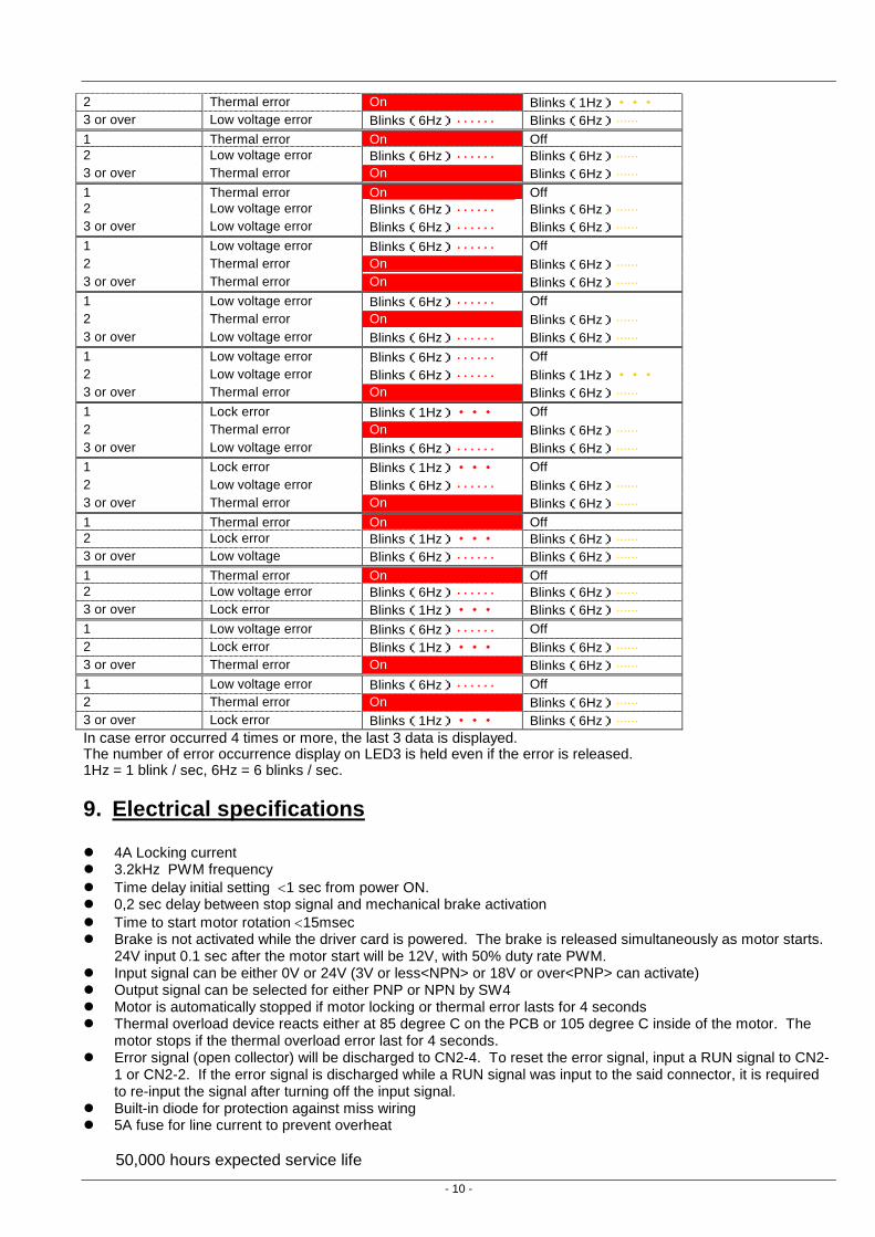
0 (non) Off Off Number of error Phenomenon LED (red) LED (Orange) 1 Lock error Blinks(1Hz)・・・ Off 2 Lock error Blinks(1Hz)・・・ Blinks(1Hz)・・・ 3 or over Lock error Blinks(1Hz)・・・ On 1 Lock error Blinks(1Hz)・・・ Off 2 Lock error Blinks(1Hz)・・・ Blinks(1Hz)・・・ 3 or over Thermal error On Blinks(6Hz)······ 1 Lock error Blinks(1Hz)・・・ Off 2 Thermal error On Blinks(6Hz)······ 3 or over Lock error Blinks(1Hz)・・・ Blinks(6Hz)······ 1 Lock error Blinks(1Hz)・・・ Off 2 Thermal error On Blinks(6Hz)······ 3 or over Thermal error On Blinks(6Hz)······ 1 Thermal error On Off 2 Lock error Blinks(1Hz)・・・ Blinks(6Hz)······ 3 or over Lock error Blinks(1Hz)・・・ Blinks(6Hz)······ 1 Thermal error On Off 2 Lock error Blinks(1Hz)・・・ Blinks(6Hz)······ 3 or over Thermal error On Blinks(6Hz)······ 1 Thermal error On Off 2 Thermal error On Blinks(1Hz)・・・ 3 or over Lock error Blinks(1Hz)・・・ Blinks(6Hz)······ 1 Thermal error On Off 2 Thermal error On Blinks(1Hz)・・・ 3 or over Thermal error On On 1 Lock error Blinks(1Hz)・・・ Off 2 Lock error Blinks(1Hz)・・・ Blinks(1Hz)・・・ 3 or over Low voltage error Blinks(6Hz)・・・・・・ Blinks(6Hz)······ 1 Lock error Blinks(1Hz)・・・ Off 2 Low voltage error Blinks(6Hz)・・・・・・ Blinks(6Hz)······ 3 or over Lock error Blinks(1Hz)・・・ Blinks(6Hz)······ 1 Lock error Blinks(1Hz)・・・ Off 2 Low voltage error Blinks(6Hz)・・・・・・ Blinks(6Hz)······ 3 or over Low voltage error Blinks(6Hz)・・・・・・ Blinks(6Hz)······ 1 Low voltage error Blinks(6Hz)・・・・・・ Off 2 Lock error Blinks(1Hz)・・・ Blinks(6Hz)······ 3 or over Lock error Blinks(1Hz)・・・ Blinks(6Hz)······ 1 Low voltage error Blinks(6Hz)・・・・・・ Off 2 Lock error Blinks(1Hz)・・・ Blinks(6Hz)······ 3 or over Low voltage error Blinks(6Hz)・・・・・・ Blinks(6Hz)······ 1 Low voltage error Blinks(6Hz)・・・・・・ Off 2 Low voltage error Blinks(6Hz)・・・・・・ Blinks(1Hz)・・・ 3 or over Lock error Blinks(1Hz)・・・ Blinks(6Hz)······ 1 Low voltage error Blinks(6Hz)・・・・・・ Off 2 Low voltage error Blinks(6Hz)・・・・・・ Blinks(1Hz)・・・ 3 or over Low voltage error Blinks(6Hz)・・・・・・ On 1 Thermal error On Off
- 10 -
2 Thermal error On Blinks(1Hz)・・・ 3 or over Low voltage error Blinks(6Hz)・・・・・・ Blinks(6Hz)······ 1 Thermal error On Off 2 Low voltage error Blinks(6Hz)・・・・・・ Blinks(6Hz)······ 3 or over Thermal error On Blinks(6Hz)······ 1 Thermal error On Off 2 Low voltage error Blinks(6Hz)・・・・・・ Blinks(6Hz)······ 3 or over Low voltage error Blinks(6Hz)・・・・・・ Blinks(6Hz)······ 1 Low voltage error Blinks(6Hz)・・・・・・ Off 2 Thermal error On Blinks(6Hz)······ 3 or over Thermal error On Blinks(6Hz)······ 1 Low voltage error Blinks(6Hz)・・・・・・ Off 2 Thermal error On Blinks(6Hz)······ 3 or over Low voltage error Blinks(6Hz)・・・・・・ Blinks(6Hz)······ 1 Low voltage error Blinks(6Hz)・・・・・・ Off 2 Low voltage error Blinks(6Hz)・・・・・・ Blinks(1Hz)・・・ 3 or over Thermal error On Blinks(6Hz)······ 1 Lock error Blinks(1Hz)・・・ Off 2 Thermal error On Blinks(6Hz)······ 3 or over Low voltage error Blinks(6Hz)・・・・・・ Blinks(6Hz)······ 1 Lock error Blinks(1Hz)・・・ Off 2 Low voltage error Blinks(6Hz)・・・・・・ Blinks(6Hz)······ 3 or over Thermal error On Blinks(6Hz)······ 1 Thermal error On Off 2 Lock error Blinks(1Hz)・・・ Blinks(6Hz)······ 3 or over Low voltage Blinks(6Hz)・・・・・・ Blinks(6Hz)······ 1 Thermal error On Off 2 Low voltage error Blinks(6Hz)・・・・・・ Blinks(6Hz)······ 3 or over Lock error Blinks(1Hz)・・・ Blinks(6Hz)······ 1 Low voltage error Blinks(6Hz)・・・・・・ Off 2 Lock error Blinks(1Hz)・・・ Blinks(6Hz)······ 3 or over Thermal error On Blinks(6Hz)······ 1 Low voltage error Blinks(6Hz)・・・・・・ Off 2 Thermal error On Blinks(6Hz)······ 3 or over Lock error Blinks(1Hz)・・・ Blinks(6Hz)······ In case error occurred 4 times or more, the last 3 data is displayed. The number of error occurrence display on LED3 is held even if the error is released. 1Hz = 1 blink / sec, 6Hz = 6 blinks / sec.
9. Electrical specifications 4A Locking current 3.2kHz PWM frequency Time delay initial setting 1 sec from power ON. 0,2 sec delay between stop signal and mechanical brake activation Time to start motor rotation 15msec Brake is not activated while the driver card is powered. The brake is released simultaneously as motor starts.
24V input 0.1 sec after the motor start will be 12V, with 50% duty rate PWM. Input signal can be either 0V or 24V (3V or less<NPN> or 18V or over<PNP> can activate) Output signal can be selected for either PNP or NPN by SW4 Motor is automatically stopped if motor locking or thermal error lasts for 4 seconds Thermal overload device reacts either at 85 degree C on the PCB or 105 degree C inside of the motor. The
motor stops if the thermal overload error last for 4 seconds. Error signal (open collector) will be discharged to CN2-4. To reset the error signal, input a RUN signal to CN2-
1 or CN2-2. If the error signal is discharged while a RUN signal was input to the said connector, it is required to re-input the signal after turning off the input signal.
Built-in diode for protection against miss wiring 5A fuse for line current to prevent overheat
50,000 hours expected service life

- 11 -
10. Environmental concerns Ambient temperature: between 0 and 40C (no condensation) Ambient humidity: < 90%RH Atmosphere: no corrosive gas Vibration: < 0.5G Indoor use only
11. Precautions to ensure the best performance Use stable power supply, that won’t be influenced by load. When DC power supply gets heat, it normally tries to reduce the output current to avoid the further
temperature rise. It this doesn’t work sufficiently yet, it will then start deducing voltage, which could be lower than 15V. Low voltage error might happen more with battery before it reaches down to discharging voltage.
Capacity of the 24VDC power supply should be greater than 5A. The power supply should not activate its protection in 1msec or less for 20A peak current. This is important to ensure the service life of the power supply, driver card and to prevent the malfunctions.
Make sure the power is shut off before mounting or removing the CN 3 motor connector. Otherwise, back EMF could damage the PCB or the risk of electrical shock arises.
Do not start or stop the motor from the power line. This could shorten the service life of the product. The driver card requires 1 second to activate a motor since it is first powered. (motor won’t run for a second
since the card is first powered) Do not use relay or contactor near the power line, signal line or the driver card. The ON/OFF switching could
generate noise that may cause malfunction of the driver card. Do not remove the motor cable while the motor is in operation. This could cause damage or malfunction. Conveyor should connect to ground.
Specifications are subject to change without prior notice.