Embed Size (px)
Citation preview
TechnicalDocumentation
HEADQUARTERS: DK-2850 Nærum · Denmark · Telephone: +45 4580 0500 · Fax: +45 4580 1405 · www.bksv.com · [email protected]
Australia (+61) 2 9889-8888 · Austria (+43) 1 865 74 00 · Brazil (+55)11 5188-8166 · Canada (+1) 514 695-8225China (+86) 10 680 29906 · Czech Republic (+420) 2 6702 1100 · Finland (+358) 9-521 300 · France (+33) 1 69 90 71 00Germany (+49) 421 17 87 0 · Hong Kong (+852) 2548 7486 · Hungary (+36) 1 215 83 05 · Ireland (+353) 1 807 4083Italy (+39) 0257 68061 · Japan (+81) 3 5715 1612 · Korea (+82) 2 3473 0605 · Netherlands (+31)318 55 9290 · Norway (+47) 66 77 11 55Poland (+48) 22 816 75 56 · Portugal (+351) 21 47 11 4 53 · Singapore (+65) 377 4512 · Slovak Republic (+421) 25 443 0701Spain (+34) 91 659 0820 · Sweden (+46) 8 449 8600 · Switzerland (+41) 44 880 7035 · Taiwan (+886) 2 2502 7255United Kingdom (+44) 14 38 739 000 · USA (+1) 800 332 2040
Local representatives and service organisations worldwide
Hand-held Analyzer Type 2250
With 2250 Sound Level Meter Software BZ 7222,2250 Frequency Analysis Software BZ 7223 and2250 Logging Software BZ 7224 and2250 Sound Recording Option BZ 7226
English BE 1713 – 15
User Manual
ËBE-1713---|Î
BE1713-15_Cover.fm Page 1 Tuesday, August 30, 2005 2:40 PM
BE 1713−15 September 2005
Hand-held Analyzer Type 2250
with 2250 Sound Level Meter Software BZ 7222,2250 Frequency Analysis Software BZ 7223,
2250 Logging Software BZ 7224 and2250 Sound Recording Option BZ 7226
User Manual
TrademarksMicrosoft and Windows are registered trademarks of Microsoft Corporation.PCL is a registered trademark of the Hewlett-Packard Company.Pentium is a registered trademark of Intel Corporation or its subsidiaries.
Copyright © 2005, Brüel & Kjær Sound & Vibration Measurement A/SAll rights reserved. No part of this publication may be reproduced or distributed in any form,or by any means, without prior written consent from Brüel & Kjær Sound & Vibration Meas-urement A/S, Nærum, Denmark
Safety ConsiderationsThis apparatus has been designed and tested in accordance with IEC 61010 � 1 andEN 61010 � 1 Safety Requirements for Electrical Equipment for Measurement, Controland Laboratory Use. This manual contains information and warnings which must be fol-lowed to ensure safe operation and to retain the apparatus in safe condition. Special noteshould be made of the following:
Safety Symbols
The apparatus will be marked with this symbol when it is important that you refer to theassociated warning statements given in the manual.
Protective Earth Terminal Hazardous Voltage
Explosion HazardThe equipment is not designed to be used in potentially explosive environments. It should notbe operated in the presence of flammable liquids or gases.
Warnings� Switch off all power to equipment before connecting or disconnecting their digital inter-
face. Failure to do so could damage the equipment.� Whenever it is likely that the correct function or operating safety of the apparatus has
been impaired, it must be made inoperative and be secured against unintended operation.� Any adjustment, maintenance and repair of the open apparatus under voltage must be
avoided as far as possible and, if unavoidable, must be carried out only by trained servicepersonnel.
� Do not dispose of electronic equipment as unsorted municipal waste� It is your responsibility to contribute to a clean and healthy environment
by using the appropriate local return and collection systems� Hazardous substances in electronic equipment may have detrimental effects
on the environment and human health� The symbol shown to the left indicates that separate collection systems
must be used for any discarded equipment marked with that symbol
Table of Contents
CHAPTER 1Introduction......................................................................................................... 1Welcome ................................................................................................................................... 1How to Use this Manual ............................................................................................................ 1
Conventions Used in this Manual ................................................................................... 1Beginners ....................................................................................................................... 2Experienced Users of Acoustic Measurement Equipment.............................................. 2
CHAPTER 2Assembling your Type 2250.............................................................................. 3Introduction................................................................................................................................ 3Instrument Components ............................................................................................................ 3Description of Inputs/Outputs .................................................................................................... 6
Top Socket ..................................................................................................................... 6USB Interface ................................................................................................................. 6Earphone ........................................................................................................................ 6Output ............................................................................................................................. 6Trigger Input ................................................................................................................... 6Input................................................................................................................................ 7External Power ............................................................................................................... 7Battery Charge Indicator................................................................................................. 8Reset Button................................................................................................................... 8Slot for Compact Flash (CF) Cards ................................................................................ 8Slot for Secure Digital (SD) Cards.................................................................................. 8
Hardware Setup ........................................................................................................................ 9Assembling Type 2250............................................................................................................ 10
Charging the Battery for the First Time......................................................................... 10Making Good Measurements ....................................................................................... 10Alternative Measurement Method (Extended Microphone) .......................................... 11Measuring for Convenience.......................................................................................... 12
CHAPTER 3Making your First Measurement ..................................................................... 13Introduction.............................................................................................................................. 13�Point and Shoot� .................................................................................................................... 13
Congratulations! ........................................................................................................... 14Making a Measurement........................................................................................................... 14
What is a Project Template? ........................................................................................ 14Switching On ................................................................................................................ 14Set the Sound Level Meter Project Template............................................................... 15
Save your Measurement ......................................................................................................... 18Viewing the Saved Measurement ................................................................................. 19
Document your Measurement ................................................................................................. 20
CHAPTER 4Getting to Know Your Type 2250 .................................................................... 23What is a Sound Level Meter? ................................................................................................ 23What is Hand-held Analyzer Type 2250?................................................................................ 24
Built-in Help .................................................................................................................. 25What is Utility Software for Hand-held Analyzers BZ 5503?.................................................... 25Basic Principles when using Type 2250.................................................................................. 26
Navigation Principles � �Star� Navigation Concept ....................................................... 26The Display Screen ...................................................................................................... 29Use of Pushbuttons for Controlling Measurements ...................................................... 32On-screen Feedback and Traffic Light ......................................................................... 33Use of Stylus and Navigation Pushbuttons .................................................................. 33How to Change Parameter Values ............................................................................... 34Locking the Pushbuttons and Display .......................................................................... 36
CHAPTER 5Calibration......................................................................................................... 37Introduction.............................................................................................................................. 37Acoustic Calibration................................................................................................................. 37Sound Level Calibrator............................................................................................................ 37
Standard Calibration..................................................................................................... 37Calibration Settings ...................................................................................................... 39
Electrical Calibration................................................................................................................ 40Calibration History ................................................................................................................... 40Transducer Database.............................................................................................................. 40
CHAPTER 6Data Management............................................................................................. 43Organising Measurements ...................................................................................................... 43
Description of Jobs and Projects .................................................................................. 43Navigating in Jobs ........................................................................................................ 44
Selecting Default Measurement Job/Path ............................................................................... 45Recalling Measurements......................................................................................................... 45
Viewing Data ................................................................................................................ 45Re-using Setups from Projects..................................................................................... 46Viewing or Listening to Annotations ............................................................................. 46
Inserting Annotations Using Explorer ...................................................................................... 47
CHAPTER 7Transferring Data to Your PC, Post-processing and Reporting .................. 49Transferring Measurement Data to Your PC........................................................................... 49Post-processing and Reporting ............................................................................................... 50
CHAPTER 8Advanced Use of Type 2250 � Tips and Tricks.............................................. 51Setting your Preferences on Type 2250.................................................................................. 51
Display Settings............................................................................................................ 51Power Settings ............................................................................................................. 52
Regional Settings ......................................................................................................... 54Storage Settings ........................................................................................................... 55Headphone Settings ..................................................................................................... 55Multi-user Facility.......................................................................................................... 56Printer Settings ............................................................................................................. 57Modem Settings............................................................................................................ 57
Preparing your Measurements ................................................................................................ 58
CHAPTER 9Installing, Updating and Upgrading Applications ......................................... 61How to Install New Applications .............................................................................................. 61How to Update/Upgrade Applications ..................................................................................... 61How to Move a License ........................................................................................................... 62Troubleshooting....................................................................................................................... 62
Type 2250 Measurements............................................................................................ 62SD and CF Cards ......................................................................................................... 62Battery Pack and Recalibration of Battery Charge Indicator ........................................ 63Touch Screen ............................................................................................................... 64Reset Options............................................................................................................... 64
Service and Repair.................................................................................................................. 66Care, Cleaning and Storage.................................................................................................... 67
Handling the Instrument ............................................................................................... 67Cleaning the Instrument ............................................................................................... 67Storing the Instrument .................................................................................................. 67
CHAPTER 101/1- or 1/3-octave Frequency Analysis (Optional Module)............................ 69Setting up the Instrument ........................................................................................................ 69Controlling the Measurement .................................................................................................. 70Displaying the Results............................................................................................................. 70Saving Results ........................................................................................................................ 72
CHAPTER 11Logging (Optional Module).............................................................................. 73Setting up the Instrument ........................................................................................................ 73Controlling the Measurement .................................................................................................. 76
Annotating a Project ..................................................................................................... 76Recording Sound.......................................................................................................... 77
Displaying the Results............................................................................................................. 77The Profile View ........................................................................................................... 77Marking Sound Categories ........................................................................................... 80Editing Markers on Profiles........................................................................................... 81Annotate Sound Categories ......................................................................................... 82Editing Annotations on Profiles..................................................................................... 83
Saving and Recalling Results.................................................................................................. 83
CHAPTER 12Sound Recording (Optional Module) .............................................................. 85Sound Level Meter and Frequency Analysis Software............................................................ 85
Setting up the Instrument ............................................................................................. 85Controlling the Recording ............................................................................................. 86Playing the Recording .................................................................................................. 87
Logging Software .................................................................................................................... 87Setting up the Instrument ............................................................................................. 88Controlling the Recording ............................................................................................. 89Control Recording using the Stylus .............................................................................. 90Playing the Recording .................................................................................................. 90Sound Recordings on the PC ....................................................................................... 92
CHAPTER 13Specifications ................................................................................................... 93Type 2250 Platform ................................................................................................................. 94Software Specifications � 2250 Sound Level Meter Software BZ 7222 .................................. 95Software Specifications � 2250 Frequency Analysis Software BZ 7223 ................................. 97Software Specifications � 2250 Logging Software BZ 7224.................................................... 97Software Specifications � Sound Recording Option BZ 7226 ................................................. 98Software Specifications � Utility Software for Hand-held Analyzers BZ 5503 ......................... 98Ordering Information ............................................................................................................... 99Compliance with Standards................................................................................................... 100
APPENDIX ASetup Parameters ........................................................................................... 101Input ...................................................................................................................................... 101Frequency Weightings........................................................................................................... 103Bandwidth.............................................................................................................................. 104Statistics ................................................................................................................................ 104Measurement Control............................................................................................................ 105Logged Broadband................................................................................................................ 105Logged Broadband (100 ms) ................................................................................................. 106Logged Spectrum .................................................................................................................. 107Markers ................................................................................................................................. 107Level Trigger ......................................................................................................................... 108Sound Recording................................................................................................................... 110Output Socket Signal............................................................................................................. 113
APPENDIX BMeasurement Parameters.............................................................................. 115For 2250 Sound Level Meter Software BZ 7222, 2250 Frequency Analysis Software BZ 7223 and 2250 Logging Software BZ 7224 ........................................................................................... 115
Timed Measured Parameters (measured within a controlled time interval)................ 115Instantaneous Measured Parameters (available at any time) .................................... 117
For 2250 Frequency Analysis Software BZ 7223 and 2250 Logging Software BZ 7224 (if license available for BZ 7223)............................................................................................................ 117
Timed Measured Spectra (measured within a controlled time interval):..................... 117Instantaneous Measured Spectra (available at any time): ......................................... 117
For 2250 Logging Software BZ 7224..................................................................................... 117Logged Parameters .................................................................................................... 118
APPENDIX CInstrument Parameters .................................................................................. 121Current Transducer ............................................................................................................... 121Transducer Database............................................................................................................ 121
Transducer Setup ....................................................................................................... 122Calibration History ...................................................................................................... 123
Calibration Setup................................................................................................................... 124
APPENDIX DPreferences..................................................................................................... 125Display Settings..................................................................................................................... 125Power Settings ...................................................................................................................... 126Regional Settings .................................................................................................................. 127Storage Settings.................................................................................................................... 127Headphone Settings.............................................................................................................. 128Users ..................................................................................................................................... 129Printer Settings...................................................................................................................... 129Modem Settings .................................................................................................................... 130
APPENDIX EGlossary .......................................................................................................... 131INDEX ................................................................................................................. 135

1
Chapter 1Introduction
WelcomeThis user manual describes the Type 2250 Hand-held Analyzer platform, including 2250 SoundLevel Meter Software BZ 7222, 2250 Frequency Analysis Software BZ 7223, 2250 LoggingSoftware BZ 7224 and 2250 Sound Recording Software BZ 7226.
The manual explains how to perform a basic sound measurement, which parameters you canmeasure and how the instrument should be operated. In addition, some practical hints andguidelines are provided, including all relevant technical specifications. Finally, a glossary isadded to help with specific terminology found in this manual.
How to Use this Manual
Conventions Used in this ManualInstructions and descriptions that refer to Type 2250 pushbuttons are shown with the pushbuttonicons as seen on the instrument. See Chapter 2 for a list of pushbutton icons and their functions.
Menu items and buttons/tabs used on the screen
Indicated by bold type face (for example, select Calibration from the list of options).
Parameter Text Appearing on the Screen
Parameters, instructions and descriptions appearing on the screen are indicated by italics (forexample, Measurement Mode).
Path Denotations
Indicated by capitals (for example, SETUP\BZ7222\).
2 Hand-held Analyzer Type 2250 � User Manual
BeginnersBefore you read the rest of this manual, read Brüel & Kjær�s primer on Measuring Sound. Thiswill give you a basic idea of acoustic measurements. It can be found on the www.bksv.comwebsite, by typing �Primer� in the search window. The website also contains lots of otherinformation you might find useful.
Further information is available in the On-line Help installed on Type 2250.
Experienced Users of Acoustic Measurement EquipmentThe manual is designed so that you don�t have to read all of it to be able to use the instrument.It is built around the most frequently used operations, these are as follows:� Assembling your Type 2250 (see Chapter 2)� Making your First Measurement (see Chapter 3)� Getting to Know Your Type 2250 (see Chapter 4)� Calibration (see Chapter 5)� Data Management (see Chapter 6)� Transferring Data to Your PC, Post-processing and Reporting (see Chapter 7)� Advanced Use of Type 2250 � Tips and Tricks (see Chapter 8)
However, it is recommended that you read the entire manual for appropriate procedures on howto use Type 2250 to obtain accurate sound level measurement results.
3
Chapter 2Assembling your Type 2250
IntroductionThis chapter describes how to assemble and set up your Type 2250 system. It provides briefdescription and an associated diagram showing the instrument components and the various inputand output connections. This enables you to start getting familiar with the instrument, whileassembling your system.
This is followed by an overview of the hardware components, showing all the main configura-tions of the instrument and its accessories.
Finally, instructions are provided that explain how to assemble standard and optional hardwarecomponents used in your system. Once you have followed the assembly instructions, yourHand-held Analyzer will be ready to make measurements.
Instrument ComponentsAn overview of the main instrument components is provided in Fig.2.1. The descriptions thatfollow refer to those components.
4 Hand-held Analyzer Type 2250 � User Manual
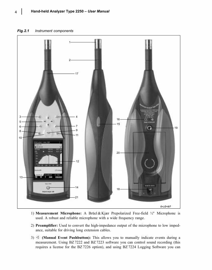
Fig.2.1 Instrument components
1) Measurement Microphone: A Brüel & Kjær Prepolarized Free-field ½″ Microphone isused. A robust and reliable microphone with a wide frequency range.
2) Preamplifier: Used to convert the high-impedance output of the microphone to low imped-ance, suitable for driving long extension cables.
3) (Manual Event Pushbutton): This allows you to manually indicate events during ameasurement. Using BZ 7222 and BZ 7223 software you can control sound recording (thisrequires a license for the BZ 7226 option), and using BZ 7224 Logging Software you can
1
2
8
3 4
6 7
11
5
9
10
12
13
14
1516
17
18
20
19
21
CHAPTER 2Assembling your Type 2250 5
insert an Event Marker and control sound recording (the latter requires a license for theBZ 7226 option).
4) (Commentary Pushbutton): This allows you to add recorded audio messages to yourmeasurement files.
5) , , , (Navigation Pushbuttons): These move the active screen component(Field Selector) and navigate the user interface.
6) (Back-erase Pushbutton): This allows you to erase the last 5 seconds of measurementdata or to insert an Exclude Marker (BZ 7224 Logging Software only).
7) (Accept Pushbutton): This allows you to accept any changes you make to the instru-ment�s setup.
8) (Reset Measurement Pushbutton): This allows you clear the current measurementfrom the screen, rather like the �C� or cancel button on a calculator.
9) (Start/Pause Pushbutton): Press this to start, pause or continue with a measurement.
10) (Status Indicator): The red, yellow or green lights, (or LEDs), referred to as the�Traffic Light� either side of the Start/Pause pushbutton, indicate important states of theinstrument during operation, i.e., measurement stopped, paused or running. See Chapter 4for further details
11) (Save Pushbutton): This allows you to save measurement results.
12) Display Screen: A high-contrast, colour, touch-sensitive screen.
13) (Main Menu icon): This calls up the Main Menu, which allows you to navigateimmediately to all the main functions of the instrument, such as Setup, Explorer (or Data-browser), Preferences, and the Calibration procedure.
14) (Power-on Pushbutton): Turns the instrument on and off. If held in for 1 second, theinstrument goes into standby mode; if held in for more than 4 seconds, it turns the instru-ment off.
15) Stylus: Stored in a holder on the side of the instrument, for use on the touch-sensitivescreen. You can choose to use the stylus or the hardkeys, depending on your preference andthe measurement situation. (Also see �Use of Stylus and Navigation Pushbuttons� in Chap-ter 4.)
16) Secondary Microphone: This is used to add recorded comments to measurements and ispositioned on the underside of the instrument.
17) Top Socket: This is the main microphone input socket for Type 2250. The MeasurementMicrophone and Preamplifier (items 1 and 2 resp.) are normally connected directly to thissocket. For more details see Description of Inputs/Outputs that follows.
18) Tripod Mounting Thread: Use this to mount Type 2250 onto the tripod and/or tripodextension.
6 Hand-held Analyzer Type 2250 � User Manual
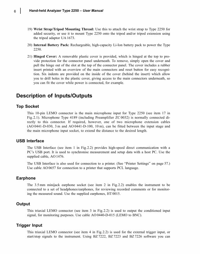
19) Wrist Strap/Tripod Mounting Thread: Use this to attach the wrist strap to Type 2250 foradded security, or use it to mount Type 2250 onto the tripod and/or tripod extension usingthe tripod adaptor UA 1673.
20) Internal Battery Pack: Rechargeable, high-capacity Li-Ion battery pack to power the Type2250.
21) Hinged Cover: A removable plastic cover is provided, which is hinged at the top to pro-vide protection for the connector panel underneath. To remove, simply open the cover andpull the hinge out of the slot at the top of the connector panel. The cover includes a rubberinsert printed with an overview of the main connectors and reset button for easy recogni-tion. Six indents are provided on the inside of the cover (behind the insert) which allowyou to drill holes in the plastic cover, giving access to the main connectors underneath, soyou can fit the cover while power is connected, for example.
Description of Inputs/Outputs
Top SocketThis 10-pin LEMO connector is the main microphone input for Type 2250 (see item 17 inFig.2.1). Microphone Type 4189 (including Preamplifier ZC 0032) is normally connected di-rectly to this connector. If required, however, one of two microphone extension cables(AO 0441-D-030, 3 m and AO 0441-D-100, 10 m), can be fitted between the input stage andthe main microphone input socket, to extend the distance to the desired length.
USB Interface The USB Interface (see item 1 in Fig.2.2) provides high-speed direct communication with aPC�s USB port. It is used to synchronise measurement and setup data with a host PC. Use thesupplied cable, AO 1476.
The USB Interface is also used for connection to a printer. (See �Printer Settings� on page 57.)Use cable AO 0657 for connection to a printer that supports PCL language.
EarphoneThe 3.5 mm minijack earphone socket (see item 2 in Fig.2.2) enables the instrument to beconnected to a set of headphones/earphones, for reviewing recorded comments or for monitor-ing the measured sound. Use the supplied earphones, HT 0015.
Output This triaxial LEMO connector (see item 3 in Fig.2.2) is used to output the conditioned inputsignal, for monitoring purposes. Use cable AO 0440-D-015 (LEMO to BNC).
Trigger InputThis triaxial LEMO connector (see item 4 in Fig.2.2) is used for the external trigger input, orstart/stop signals to the instrument. Using BZ 7222, BZ 7223 and BZ 7226 software you can
CHAPTER 2Assembling your Type 2250 7
control sound recording (this requires a license for the BZ 7226 option). If you want to start andstop the recording using an external device, connect it to this input. See details in Appendix A.
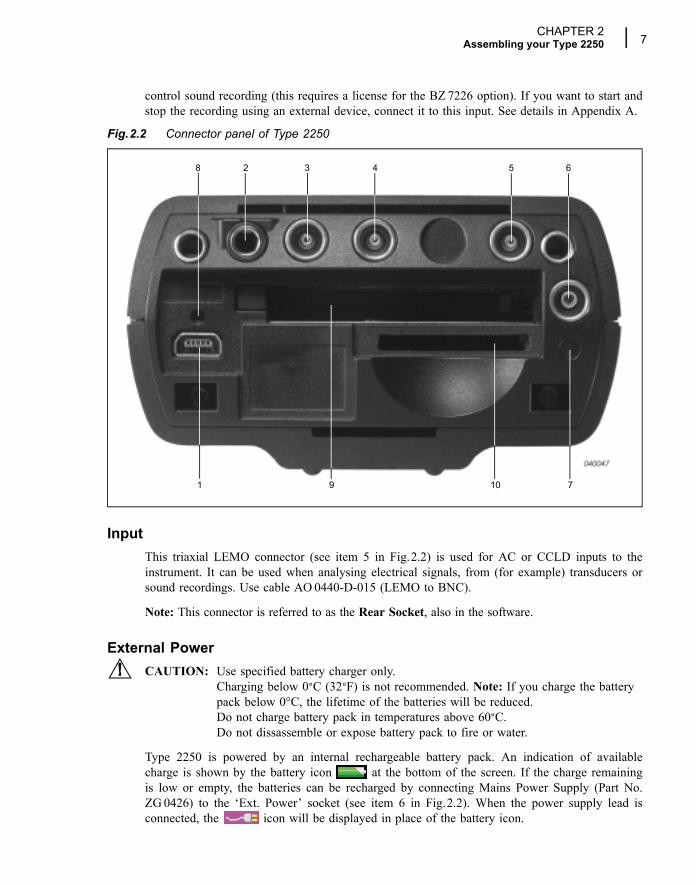
Fig.2.2 Connector panel of Type 2250
InputThis triaxial LEMO connector (see item 5 in Fig.2.2) is used for AC or CCLD inputs to theinstrument. It can be used when analysing electrical signals, from (for example) transducers orsound recordings. Use cable AO 0440-D-015 (LEMO to BNC).
Note: This connector is referred to as the Rear Socket, also in the software.
External PowerCAUTION: Use specified battery charger only.
Charging below 0°C (32°F) is not recommended. Note: If you charge the batterypack below 0°C, the lifetime of the batteries will be reduced.Do not charge battery pack in temperatures above 60°C.Do not dissassemble or expose battery pack to fire or water.
Type 2250 is powered by an internal rechargeable battery pack. An indication of availablecharge is shown by the battery icon at the bottom of the screen. If the charge remainingis low or empty, the batteries can be recharged by connecting Mains Power Supply (Part No.ZG 0426) to the �Ext. Power� socket (see item 6 in Fig.2.2). When the power supply lead isconnected, the icon will be displayed in place of the battery icon.
2
1
3 4 5 6
7
8
109
8 Hand-held Analyzer Type 2250 � User Manual
Battery Charge IndicatorA battery charge light, (LED), indicates when the battery pack is being charged from externalpower, (see item 7 in Fig.2.2). It shows a steady green light when external power is applied(and the battery is charging), and a flashing green light when charging has finished.
Reset ButtonLocated above the USB connector (see item 8 in Fig.2.2), it is used to reset the Type 2250 ifyou have problems with the instrument and cannot get it to operate. To reset, press the buttonwith the point of the stylus � see chapter 9 for troubleshooting.
Slot for Compact Flash (CF) CardsThis slot (see item 9 in Fig.2.2) accepts CF sized cards and can be used for memory or, forexample, a modem.
Slot for Secure Digital (SD) CardsThis slot (see item 10 in Fig.2.2) accepts SD memory cards and is typically used to savemeasurement data. Capacities in excess of 1 gigabyte are acceptable.
CHAPTER 2Assembling your Type 2250 9
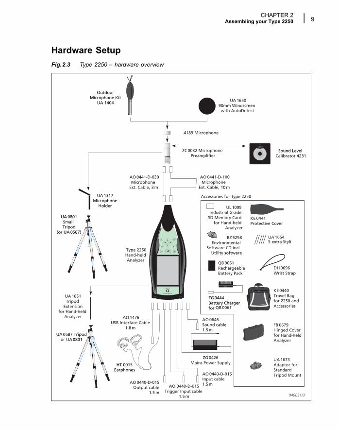
Hardware SetupFig.2.3 Type 2250 � hardware overview
UA 1317Microphone
Holder
UA 0801Small Tripod
(or UA 0587)
Sound Level Calibrator 4231
HT 0015Earphones
AO 1476USB Interface Cable
1.8 m
ZG 0426Mains Power Supply
ZC 0032 Microphone Preamplifier
4189 Microphone
UA 1651Tripod
Extensionfor Hand-held
Analyzer
UA 0587 Tripodor UA 0801
AO 0441-D-030Microphone
Ext. Cable, 3 m
AO 0441-D-100Microphone
Ext. Cable, 10 m
AO 0440-D-015Output cable
1.5 m
AO 0440-D-015Trigger Input cable
1.5 m
AO 0440-D-015Input cable1.5 m
AO 0646Sound cable1.5 m
040031/3
Accessories for Type 2250
UL 1009 Industrial Grade
SD Memory Card for Hand-held
Analyzer
Type 2250Hand-heldAnalyzer
ZG 0444 Battery Chargerfor QB 0061
QB 0061RechargeableBattery Pack
UA 16545 extra Styli
KE 0441Protective Cover
KE 0440 Travel Bag for 2250 and Accessories
FB 0679Hinged Cover for Hand-held Analyzer
UA 1673 Adaptor forStandardTripod Mount
BZ 5298Environmental
Software CD incl. Utility software
DH 0696Wrist Strap
OutdoorMicrophone Kit
UA 1404 UA 165090mm Windscreen
with AutoDetect
10 Hand-held Analyzer Type 2250 � User Manual
Assembling Type 2250
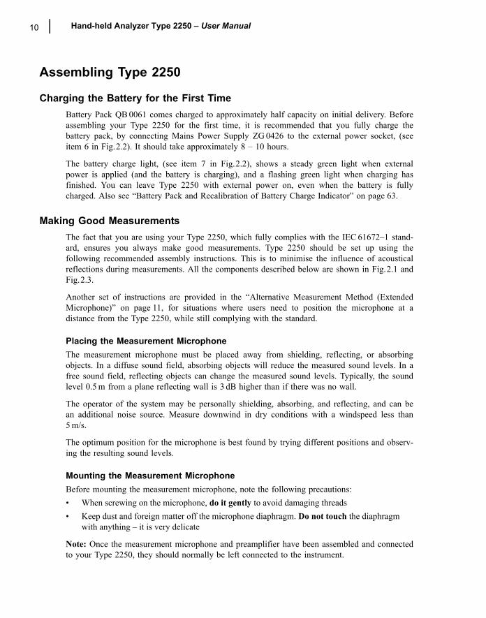
Charging the Battery for the First TimeBattery Pack QB 0061 comes charged to approximately half capacity on initial delivery. Beforeassembling your Type 2250 for the first time, it is recommended that you fully charge thebattery pack, by connecting Mains Power Supply ZG 0426 to the external power socket, (seeitem 6 in Fig.2.2). It should take approximately 8 � 10 hours.
The battery charge light, (see item 7 in Fig.2.2), shows a steady green light when externalpower is applied (and the battery is charging), and a flashing green light when charging hasfinished. You can leave Type 2250 with external power on, even when the battery is fullycharged. Also see �Battery Pack and Recalibration of Battery Charge Indicator� on page 63.
Making Good MeasurementsThe fact that you are using your Type 2250, which fully complies with the IEC 61672�1 stand-ard, ensures you always make good measurements. Type 2250 should be set up using thefollowing recommended assembly instructions. This is to minimise the influence of acousticalreflections during measurements. All the components described below are shown in Fig.2.1 andFig.2.3.
Another set of instructions are provided in the �Alternative Measurement Method (ExtendedMicrophone)� on page 11, for situations where users need to position the microphone at adistance from the Type 2250, while still complying with the standard.
Placing the Measurement MicrophoneThe measurement microphone must be placed away from shielding, reflecting, or absorbingobjects. In a diffuse sound field, absorbing objects will reduce the measured sound levels. In afree sound field, reflecting objects can change the measured sound levels. Typically, the soundlevel 0.5 m from a plane reflecting wall is 3 dB higher than if there was no wall.
The operator of the system may be personally shielding, absorbing, and reflecting, and can bean additional noise source. Measure downwind in dry conditions with a windspeed less than5 m/s.
The optimum position for the microphone is best found by trying different positions and observ-ing the resulting sound levels.
Mounting the Measurement MicrophoneBefore mounting the measurement microphone, note the following precautions:� When screwing on the microphone, do it gently to avoid damaging threads� Keep dust and foreign matter off the microphone diaphragm. Do not touch the diaphragm
with anything � it is very delicate
Note: Once the measurement microphone and preamplifier have been assembled and connectedto your Type 2250, they should normally be left connected to the instrument.
CHAPTER 2Assembling your Type 2250 11
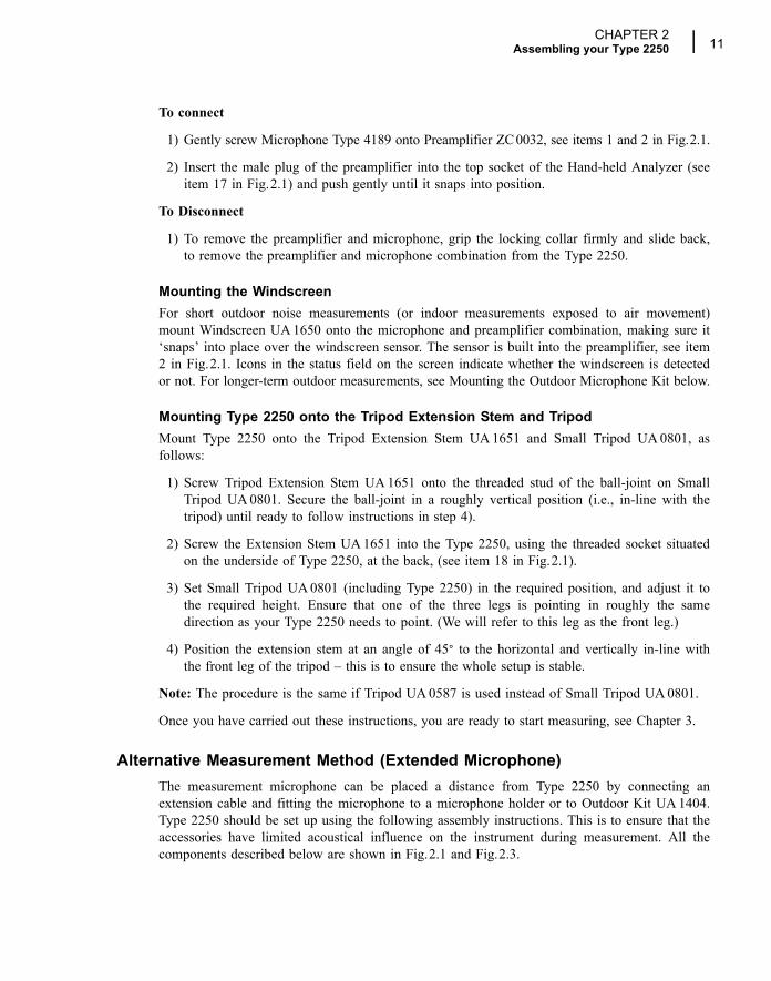
To connect
1) Gently screw Microphone Type 4189 onto Preamplifier ZC 0032, see items 1 and 2 in Fig.2.1.
2) Insert the male plug of the preamplifier into the top socket of the Hand-held Analyzer (seeitem 17 in Fig.2.1) and push gently until it snaps into position.
To Disconnect
1) To remove the preamplifier and microphone, grip the locking collar firmly and slide back,to remove the preamplifier and microphone combination from the Type 2250.
Mounting the WindscreenFor short outdoor noise measurements (or indoor measurements exposed to air movement)mount Windscreen UA 1650 onto the microphone and preamplifier combination, making sure it�snaps� into place over the windscreen sensor. The sensor is built into the preamplifier, see item2 in Fig.2.1. Icons in the status field on the screen indicate whether the windscreen is detectedor not. For longer-term outdoor measurements, see Mounting the Outdoor Microphone Kit below.
Mounting Type 2250 onto the Tripod Extension Stem and TripodMount Type 2250 onto the Tripod Extension Stem UA 1651 and Small Tripod UA 0801, asfollows:
1) Screw Tripod Extension Stem UA 1651 onto the threaded stud of the ball-joint on SmallTripod UA 0801. Secure the ball-joint in a roughly vertical position (i.e., in-line with thetripod) until ready to follow instructions in step 4).
2) Screw the Extension Stem UA 1651 into the Type 2250, using the threaded socket situatedon the underside of Type 2250, at the back, (see item 18 in Fig.2.1).
3) Set Small Tripod UA 0801 (including Type 2250) in the required position, and adjust it tothe required height. Ensure that one of the three legs is pointing in roughly the samedirection as your Type 2250 needs to point. (We will refer to this leg as the front leg.)
4) Position the extension stem at an angle of 45° to the horizontal and vertically in-line withthe front leg of the tripod � this is to ensure the whole setup is stable.
Note: The procedure is the same if Tripod UA 0587 is used instead of Small Tripod UA 0801.
Once you have carried out these instructions, you are ready to start measuring, see Chapter 3.
Alternative Measurement Method (Extended Microphone)The measurement microphone can be placed a distance from Type 2250 by connecting anextension cable and fitting the microphone to a microphone holder or to Outdoor Kit UA 1404.Type 2250 should be set up using the following assembly instructions. This is to ensure that theaccessories have limited acoustical influence on the instrument during measurement. All thecomponents described below are shown in Fig.2.1 and Fig.2.3.
12 Hand-held Analyzer Type 2250 � User Manual
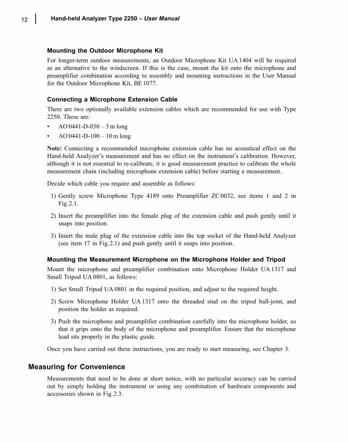
Mounting the Outdoor Microphone KitFor longer-term outdoor measurements, an Outdoor Microphone Kit UA 1404 will be requiredas an alternative to the windscreen. If this is the case, mount the kit onto the microphone andpreamplifier combination according to assembly and mounting instructions in the User Manualfor the Outdoor Microphone Kit, BE 1077.
Connecting a Microphone Extension CableThere are two optionally available extension cables which are recommended for use with Type2250. These are:� AO 0441-D-030 � 3 m long� AO 0441-D-100 � 10 m long
Note: Connecting a recommended microphone extension cable has no acoustical effect on theHand-held Analyzer�s measurement and has no effect on the instrument�s calibration. However,although it is not essential to re-calibrate, it is good measurement practice to calibrate the wholemeasurement chain (including microphone extension cable) before starting a measurement.
Decide which cable you require and assemble as follows:
1) Gently screw Microphone Type 4189 onto Preamplifier ZC 0032, see items 1 and 2 inFig.2.1.
2) Insert the preamplifier into the female plug of the extension cable and push gently until itsnaps into position.
3) Insert the male plug of the extension cable into the top socket of the Hand-held Analyzer(see item 17 in Fig.2.1) and push gently until it snaps into position.
Mounting the Measurement Microphone on the Microphone Holder and TripodMount the microphone and preamplifier combination onto Microphone Holder UA 1317 andSmall Tripod UA 0801, as follows:
1) Set Small Tripod UA 0801 in the required position, and adjust to the required height.
2) Screw Microphone Holder UA 1317 onto the threaded stud on the tripod ball-joint, andposition the holder as required.
3) Push the microphone and preamplifier combination carefully into the microphone holder, sothat it grips onto the body of the microphone and preamplifier. Ensure that the microphonelead sits properly in the plastic guide.
Once you have carried out these instructions, you are ready to start measuring, see Chapter 3.
Measuring for ConvenienceMeasurements that need to be done at short notice, with no particular accuracy can be carriedout by simply holding the instrument or using any combination of hardware components andaccessories shown in Fig.2.3.
13
Chapter 3Making your First Measurement
IntroductionThis chapter describes how to make a basic measurement and how to save and document theresults. It assumes you have just received your Hand-held Analyzer Type 2250 and are turningit on for the first time. If the instrument has been used before, and the previous user hasinitiated the multi-user facility, then the screens that are displayed may not follow the sequencedescribed below. If this is the case, please refer to the �Multi-user Facility� on page 56.
Note: A stylus is stored in a holder on the side of the instrument, see item 15 in Fig.2.1. Thiscan be used on the touch-sensitive screen to select icons and functions during the proceduresthat follow. Alternatively, you can use the various pushbuttons, see items 3 to 11 in Fig.2.1.
The following procedures assume that the measurement microphone and preamplifier have beenmounted as described in Chapter 2 and Type 2250 has a fully charged battery, see �Chargingthe Battery for the First Time� on page 10.
�Point and Shoot�Using the following basic procedure you will be able to start using your hand-held analyzerimmediately to make measurements and start the familiarisation process:
1) Switch on by pressing and make sure the SOUND LEVEL METER Project Templateis selected.
2) Check that the data path at the top of the screen displays the correct job/project, (i.e., whereyou want to save the new data).
3) Set Measurement Mode to manual and change any setup parameters by tapping the MainMenu icon and selecting Setup from the drop-down that appears.
4) Press the Start/Pause pushbutton , then monitor the status indicator (traffic light).
5) Use the Start/Pause , Continue , Back-erase and Reset pushbuttons to con-trol the measurement.
6) When measurement has finished, press the Save pushbutton to save your data.

14 Hand-held Analyzer Type 2250 � User Manual
7) Add any spoken comments to the measurements by pressing the Commentary pushbut-ton and add any written comments by tapping the Main Menu icon and selecting NewNote from the drop-down that appears.
8) To view and organise your data, tap the Main Menu icon and select Explorer.
Note: You are not required to set any measurement ranges on Type 2250, the instrument has adynamic range of more than 120 dB, from 140 dB down to the noise floor of the microphone,(if the microphone has nominal sensitivity).
Congratulations!You should now be familiar with the basic principles of the Type 2250. If you need more help,the following section goes into the measurement process in more detail. If not, please refer to�Getting to Know Your Type 2250� on page 23.
Making a Measurement
What is a Project Template?A Project Template contains all the common display settings and measurement setups requiredto perform a noise measurement. The template does not contain any measurement data � thisdata is saved as individual projects, stored in job folders, see �Description of Jobs and Projects�on page 43. The Project Templates covered by this manual, are:� Sound Level Meter Project Template (included in BZ 7222 software)� Frequency Analysis Project Template (included in BZ 7223 software)� Logging Project Template (included in BZ 7224 software)
Note: The Sound Recording Option BZ 7226 does not contain a specific template � the soundrecording options are available in all templates included in BZ 7222/23/24.
If you make any changes to the settings in a Project Template, an �*� will appear next to thetemplate name to indicate that the new settings have not been saved. Select Save Templatefrom the Main Menu to save the settings in the current template.
Switching OnSwitch Type 2250 on by pressing . The start-up time depends on the state the instrument wasin when last switched off and it may take up to 1 minute from a cold start, or up to 5 seconds ifthe instrument is already in Standby Mode, (i.e., from a warm start).
Note: A cold start is described as a re-boot of the instrument from ROM. This normally occursafter the instrument has been turned off for some time, either by the user or following anautomatic power-down. A warm start takes the instrument quickly from Standby Mode to Oper-ating Mode without having to re-boot. (The battery needs to be charged for this to happen, see�Charging the Battery for the First Time� on page 10.)
CHAPTER 3Making your First Measurement 15
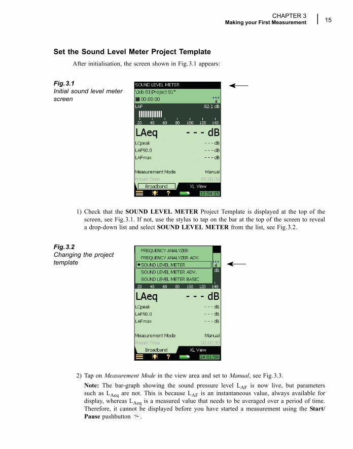
Set the Sound Level Meter Project TemplateAfter initialisation, the screen shown in Fig.3.1 appears:
Fig.3.1Initial sound level meter screen
1) Check that the SOUND LEVEL METER Project Template is displayed at the top of thescreen, see Fig.3.1. If not, use the stylus to tap on the bar at the top of the screen to reveala drop-down list and select SOUND LEVEL METER from the list, see Fig.3.2.
Fig.3.2Changing the project template
2) Tap on Measurement Mode in the view area and set to Manual, see Fig.3.3.Note: The bar-graph showing the sound pressure level LAF is now live, but parameterssuch as LAeq are not. This is because LAF is an instantaneous value, always available fordisplay, whereas LAeq is a measured value that needs to be averaged over a period of time.Therefore, it cannot be displayed before you have started a measurement using the Start/Pause pushbutton .
16 Hand-held Analyzer Type 2250 � User Manual
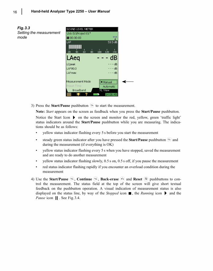
Fig.3.3Setting the measurement mode
3) Press the Start/Pause pushbutton to start the measurement.Note: Start appears on the screen as feedback when you press the Start/Pause pushbutton. Notice the Start Icon on the screen and monitor the red, yellow, green �traffic light�status indicators around the Start/Pause pushbutton while you are measuring. The indica-tions should be as follows: � yellow status indicator flashing every 5 s before you start the measurement
� steady green status indicator after you have pressed the Start/Pause pushbutton and during the measurement (if everything is OK)
� yellow status indicator flashing every 5 s when you have stopped, saved the measurement and are ready to do another measurement
� yellow status indicator flashing slowly, 0.5 s on, 0.5 s off, if you pause the measurement� red status indicator flashing rapidly if you encounter an overload condition during the
measurement
4) Use the Start/Pause , Continue , Back-erase and Reset pushbuttons to con-trol the measurement. The status field at the top of the screen will give short textualfeedback on the pushbutton operation. A visual indication of measurement status is alsodisplayed on the status line, by way of the Stopped icon , the Running icon and thePause icon . See Fig.3.4.
CHAPTER 3Making your First Measurement 17
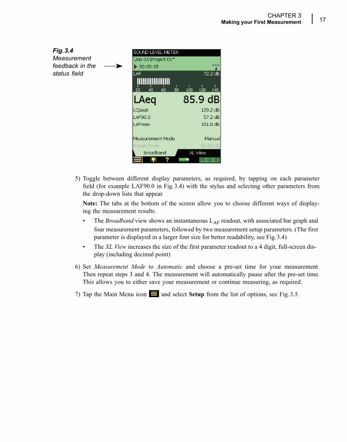
Fig.3.4Measurement feedback in the status field
5) Toggle between different display parameters, as required, by tapping on each parameterfield (for example LAF90.0 in Fig.3.4) with the stylus and selecting other parameters fromthe drop-down lists that appear.Note: The tabs at the bottom of the screen allow you to choose different ways of display-ing the measurement results. � The Broadband view shows an instantaneous LAF readout, with associated bar graph and
four measurement parameters, followed by two measurement setup parameters. (The first parameter is displayed in a larger font size for better readability, see Fig.3.4)
� The XL View increases the size of the first parameter readout to a 4 digit, full-screen dis-play (including decimal point)
6) Set Measurement Mode to Automatic and choose a pre-set time for your measurement.Then repeat steps 3 and 4. The measurement will automatically pause after the pre-set time.This allows you to either save your measurement or continue measuring, as required.
7) Tap the Main Menu icon and select Setup from the list of options, see Fig.3.5.
18 Hand-held Analyzer Type 2250 � User Manual
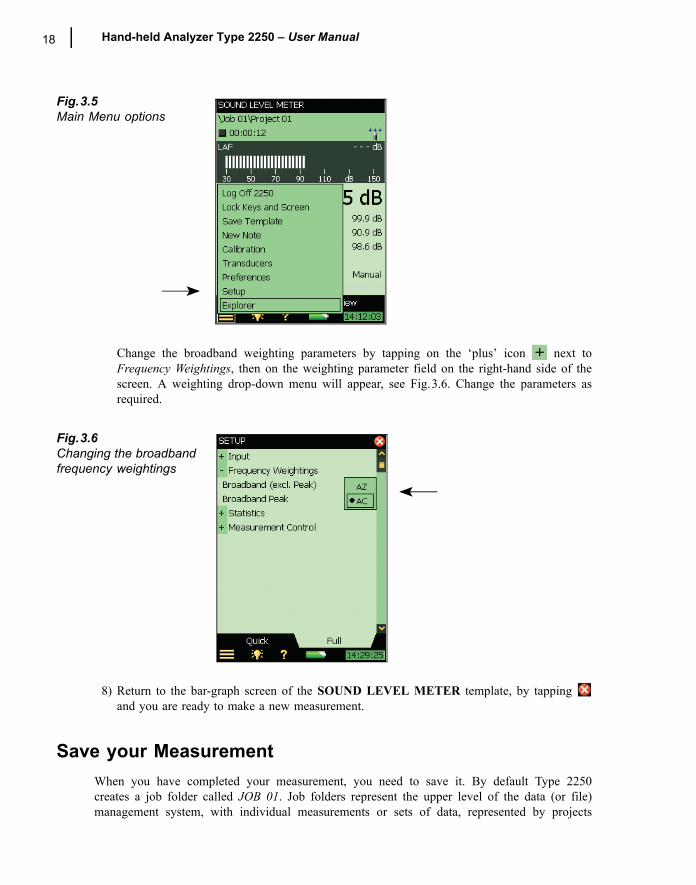
Fig.3.5Main Menu options
Change the broadband weighting parameters by tapping on the �plus� icon next toFrequency Weightings, then on the weighting parameter field on the right-hand side of thescreen. A weighting drop-down menu will appear, see Fig.3.6. Change the parameters asrequired.
Fig.3.6Changing the broadband frequency weightings
8) Return to the bar-graph screen of the SOUND LEVEL METER template, by tapping and you are ready to make a new measurement.
Save your MeasurementWhen you have completed your measurement, you need to save it. By default Type 2250creates a job folder called JOB 01. Job folders represent the upper level of the data (or file)management system, with individual measurements or sets of data, represented by projects
CHAPTER 3Making your First Measurement 19
appearing under the relevant job. By default Type 2250 also creates a project called Project 01under JOB 01. (Subsequent measurements will be labelled Project 02, Project 03, etc., underJOB 01. This will happen each time you have saved a measurement.)
Check that the data path at the top of the screen displays \JOB 01\Project 01* and save yourmeasurement by pressing the Save pushbutton . For more details refer to �Organising Meas-urements� on page 43.
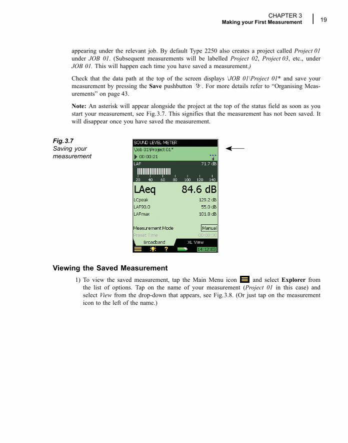
Note: An asterisk will appear alongside the project at the top of the status field as soon as youstart your measurement, see Fig.3.7. This signifies that the measurement has not been saved. Itwill disappear once you have saved the measurement.
Fig.3.7Saving your measurement
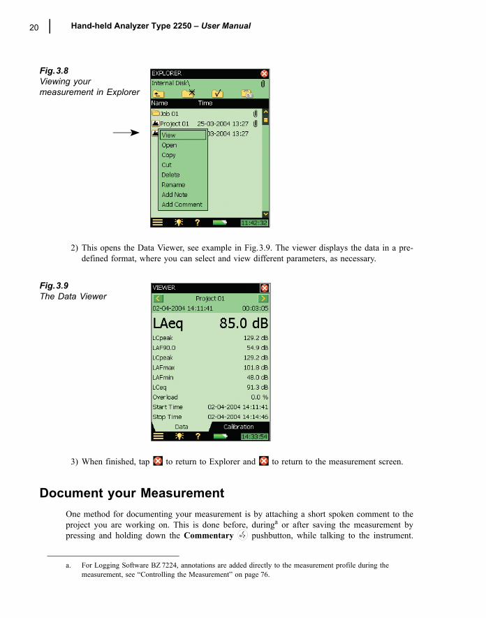
Viewing the Saved Measurement1) To view the saved measurement, tap the Main Menu icon and select Explorer from
the list of options. Tap on the name of your measurement (Project 01 in this case) andselect View from the drop-down that appears, see Fig.3.8. (Or just tap on the measurementicon to the left of the name.)
20 Hand-held Analyzer Type 2250 � User Manual
Fig.3.8Viewing your measurement in Explorer
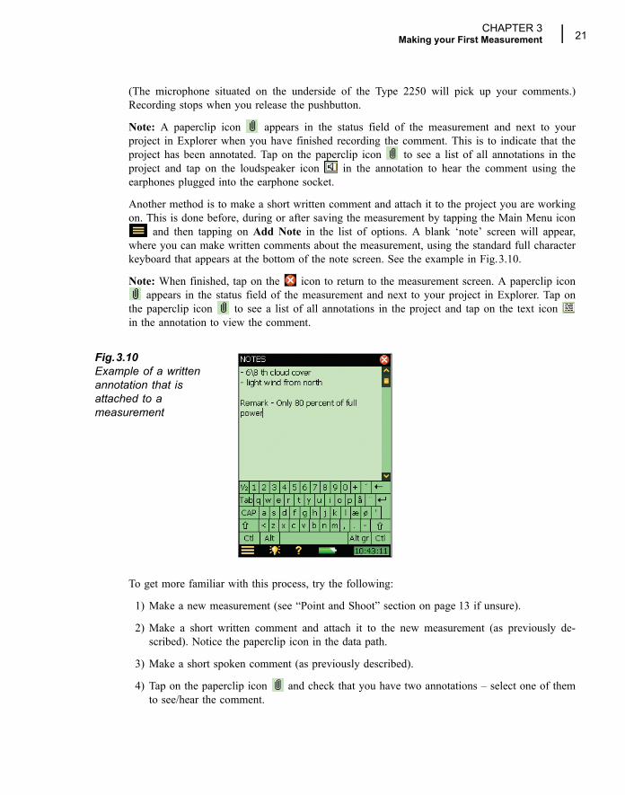
2) This opens the Data Viewer, see example in Fig.3.9. The viewer displays the data in a pre-defined format, where you can select and view different parameters, as necessary.
Fig.3.9The Data Viewer
3) When finished, tap to return to Explorer and to return to the measurement screen.
Document your MeasurementOne method for documenting your measurement is by attaching a short spoken comment to theproject you are working on. This is done before, duringa or after saving the measurement bypressing and holding down the Commentary pushbutton, while talking to the instrument.
a. For Logging Software BZ 7224, annotations are added directly to the measurement profile during the measurement, see �Controlling the Measurement� on page 76.
CHAPTER 3Making your First Measurement 21
(The microphone situated on the underside of the Type 2250 will pick up your comments.)Recording stops when you release the pushbutton.
Note: A paperclip icon appears in the status field of the measurement and next to yourproject in Explorer when you have finished recording the comment. This is to indicate that theproject has been annotated. Tap on the paperclip icon to see a list of all annotations in theproject and tap on the loudspeaker icon in the annotation to hear the comment using theearphones plugged into the earphone socket.
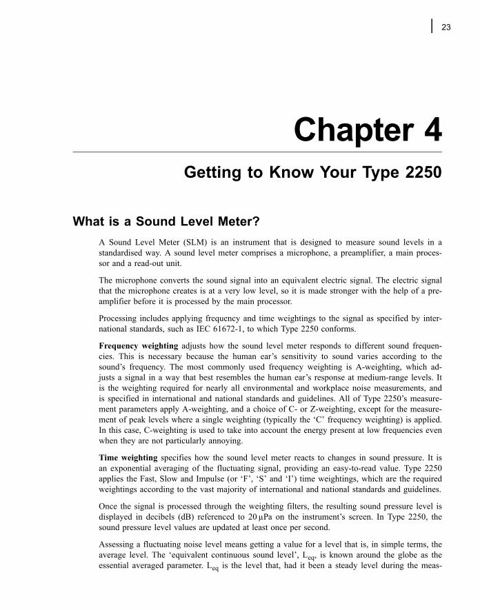
Another method is to make a short written comment and attach it to the project you are workingon. This is done before, during or after saving the measurement by tapping the Main Menu icon
and then tapping on Add Note in the list of options. A blank �note� screen will appear,where you can make written comments about the measurement, using the standard full characterkeyboard that appears at the bottom of the note screen. See the example in Fig.3.10.
Note: When finished, tap on the icon to return to the measurement screen. A paperclip icon appears in the status field of the measurement and next to your project in Explorer. Tap on
the paperclip icon to see a list of all annotations in the project and tap on the text icon in the annotation to view the comment.
Fig.3.10Example of a written annotation that is attached to a measurement
To get more familiar with this process, try the following:
1) Make a new measurement (see �Point and Shoot� section on page 13 if unsure).
2) Make a short written comment and attach it to the new measurement (as previously de-scribed). Notice the paperclip icon in the data path.
3) Make a short spoken comment (as previously described).
4) Tap on the paperclip icon and check that you have two annotations � select one of themto see/hear the comment.

22 Hand-held Analyzer Type 2250 � User Manual
23
Chapter 4Getting to Know Your Type 2250
What is a Sound Level Meter?A Sound Level Meter (SLM) is an instrument that is designed to measure sound levels in astandardised way. A sound level meter comprises a microphone, a preamplifier, a main proces-sor and a read-out unit.
The microphone converts the sound signal into an equivalent electric signal. The electric signalthat the microphone creates is at a very low level, so it is made stronger with the help of a pre-amplifier before it is processed by the main processor.
Processing includes applying frequency and time weightings to the signal as specified by inter-national standards, such as IEC 61672-1, to which Type 2250 conforms.
Frequency weighting adjusts how the sound level meter responds to different sound frequen-cies. This is necessary because the human ear�s sensitivity to sound varies according to thesound�s frequency. The most commonly used frequency weighting is A-weighting, which ad-justs a signal in a way that best resembles the human ear�s response at medium-range levels. Itis the weighting required for nearly all environmental and workplace noise measurements, andis specified in international and national standards and guidelines. All of Type 2250�s measure-ment parameters apply A-weighting, and a choice of C- or Z-weighting, except for the measure-ment of peak levels where a single weighting (typically the �C� frequency weighting) is applied.In this case, C-weighting is used to take into account the energy present at low frequencies evenwhen they are not particularly annoying.
Time weighting specifies how the sound level meter reacts to changes in sound pressure. It isan exponential averaging of the fluctuating signal, providing an easy-to-read value. Type 2250applies the Fast, Slow and Impulse (or �F�, �S� and �I�) time weightings, which are the requiredweightings according to the vast majority of international and national standards and guidelines.
Once the signal is processed through the weighting filters, the resulting sound pressure level isdisplayed in decibels (dB) referenced to 20 µPa on the instrument�s screen. In Type 2250, thesound pressure level values are updated at least once per second.
Assessing a fluctuating noise level means getting a value for a level that is, in simple terms, theaverage level. The �equivalent continuous sound level�, Leq, is known around the globe as theessential averaged parameter. Leq is the level that, had it been a steady level during the meas-
24 Hand-held Analyzer Type 2250 � User Manual
urement period, would represent the amount of energy present in the measured, fluctuatingsound pressure level. It is a measure of the averaged energy in a varying sound level. It is not adirect measure of annoyance, though extensive research has shown that Leq correlates well withannoyance.
Leq is measured directly with a hand-held analyzer, such as Type 2250 running 2250 SoundLevel Meter Software BZ 7222. If an A-weighting filter is used, it is expressed as LAeq, definedas the measurement of the equivalent continuous sound level using the A-weighted filter net-work.
A full range of measurement parameters is given in Appendix B.
What is Hand-held Analyzer Type 2250?Hand-held Analyzer Type 2250 is a Class 1 modular precision integrating-averaging sound levelanalyzer with an easy to use interface for quick and simple measurement setups. Type 2250Sound Level Meter Software BZ 7222 is pre-installed on the analyzer for measuring a compre-hensive set of parameters used for rating noise in terms of its impact on the environmental andworking environments.
The more commonly used parameters, which cover a large range of applications, are eitherinstantaneous measured parameters (available at any time) or timed measured parameters (meas-ured within a controlled time interval):
Timed Measured Parameters� Equivalent Continuous Sound Levels (Leq � example: LAeq)� Peak Sound Levels (Lpeak � example: LCpeak)� Maximum Time-weighted Sound Levels (Lmax � example: LAFmax)� Minimum Time-weighted Sound Levels (Lmin � example: LAFmin)� Percentile Levels (LN � example: LAF90.0)� Sound Exposure Level (LAE)
Instantaneous Measured Parameters� Instantaneous Time-weighted Sound Levels (Lp � example: LAF)� Sound Pressure Levels (max levels once per second � example: LAF(SPL)
Note: See Appendix B for a comprehensive list of all parameters.
2250 Sound Level Meter software BZ 7222 incorporates a simple user interface which is easy tolearn and uses intuitive data storage and recall. Comprehensive security features means no lossof data, even on accidental power-off. Smart features are built-in for field use, for example,allowing you to personalise your measurements. 2250 Sound Level Meter software BZ 7222also provides connectivity between your PC and other sound analysis software.
This highly versatile hand-held analyzer platform includes a range of optional software mod-ules, that are enabled through easily activated software license keys. The combination of soft-ware modules and innovative hardware makes the instrument a dedicated solution for
CHAPTER 4Getting to Know Your Type 2250 25
performing all your high-precision measurement tasks. The following optional software moduleis covered in this manual:
2250 Frequency Analysis Software Module BZ 7223This software module allows real-time frequency measurements in 1/1- and 1/3-octave bands,making it a simple matter to, for example, select suitable hearing protection, qualify noise fromheat and ventilation systems and assess tonality.
2250 Logging Software Module BZ 7224This software module allows logging of broadband and spectral dataa to obtain a time historyfor later analysis, for example, for use in environmental noise as well as workplace noiseassessment. It allows free selection of up to 10 parameters to log at periods from 1 s to 24 h.Results are logged directly to CF or SD memory cards.
2250 Sound Recording Option BZ 7226
This option allows recording of sound during measurement using one of the software modulesBZ 7222, BZ 7223 or BZ 7224. The sound recording can be controlled manually or by using anexternal trigger signal. The recording can also be triggered when a measured parameter exceedsa preset level (BZ 7224 only). The recorded sound can be played back and listened to using thesupplied earphones, HT 0015. Sound is recorded directly to CF or SD memory cards.
Built-in HelpIf you need more detailed information at any time during operation, tap the Help icon on theinstrument�s screen. The resulting screen will explain that particular item in much more detail.You can scroll up and down the explanatory text using either the and pushbuttons, or thescrollbar on the screen. Return to the normal display screen by tapping .
Once in the help system, you can access the list of installed software versions and licenses,together with information about the hardware. This information is always available and is ac-cessed by selecting About from the top of the display.
If you need to view any of the previous 10 screens you have visited in the help system, pressthe icon at the top of the display.
What is Utility Software for Hand-held Analyzers BZ 5503?Utility Software for Hand-held Analyzers BZ 5503 functions as the link between the Type 2250and reporting software on a PC, such as Noise Explorer Type 7815, Evaluator Type 7820/21 orProtector Type 7825.
The software enables you to do the following:� setup or control Type 2250 from a PC� retrieve data from Type 2250
a. Requires Frequency Analysis Software BZ 7223
26 Hand-held Analyzer Type 2250 � User Manual
� manage and archive data from Type 2250� export data to Type 7815, Type 7820, Type 7825 or Microsoft® Excel� update the software in Type 2250� install license for use of software modules in Type 2250
Utility Software for Hand-held Analyzers BZ 5503 is supplied on the Environmental SoftwareCD-ROM (BZ 5298), which is included with your Type 2250.
Basic Principles when using Type 2250
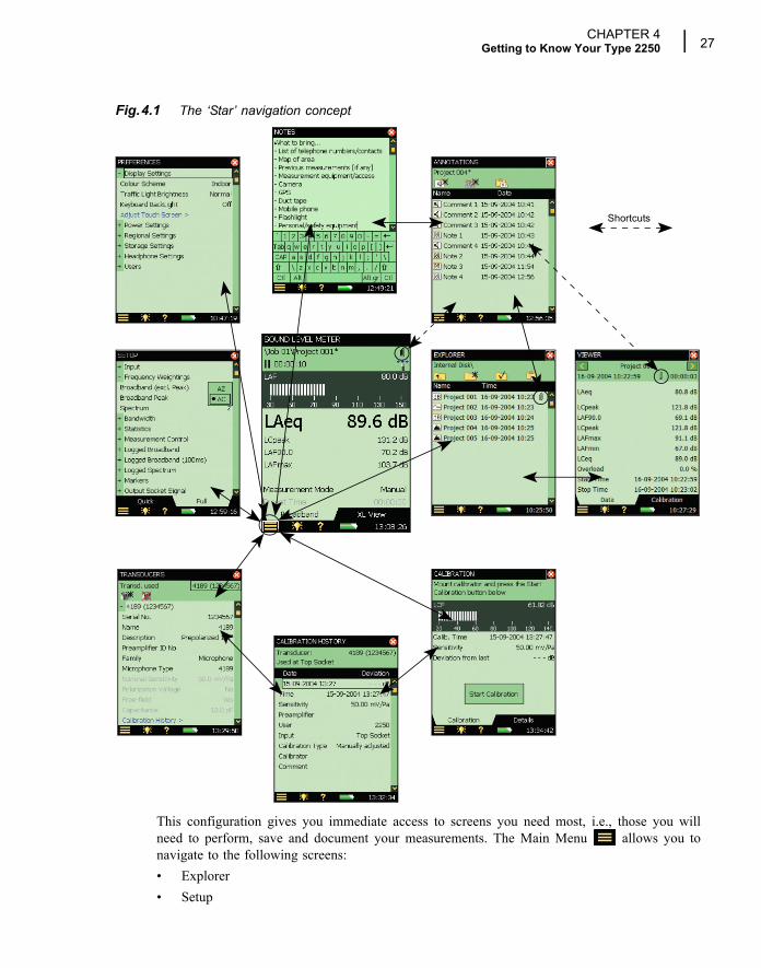
Navigation Principles � �Star� Navigation ConceptThe main principle is that all the main menus are accessible via a single tap of the stylus. TheMain Menu icon forms the centre of the �star� navigation concept, see Fig.4.1:
CHAPTER 4Getting to Know Your Type 2250 27
Fig.4.1 The �Star� navigation concept
This configuration gives you immediate access to screens you need most, i.e., those you willneed to perform, save and document your measurements. The Main Menu allows you tonavigate to the following screens:� Explorer� Setup
Shortcuts
28 Hand-held Analyzer Type 2250 � User Manual
� Preferences� Transducers� Calibration� New note
In addition, the Main Menu also allows you to perform the following actions:� Save Template� Lock Keys and Screen� Log Off
ExplorerThe Explorer screen is accessed from the Main Menu, and gives you access to the instrument�sData/Project manager. This allows you to view the overall project structure, including job fold-ers and projects, and to view all the individual measurements. When you have finished, press
to return to the measurement screen.
You can tap on any measurement file to view the saved measurement and if there are any voiceor text annotations attached, these can be viewed by tapping the paperclip icon visible next toall measurement files with attachments. When you have finished reading or listening to thecomments, press to return to the Explorer screen.
SetupThe Setup screen is accessed from the Main Menu and gives you access to the various setupparameters, such as frequency weightings, control of the measurement, bandwidth, statistics andthe type of input currently connected. You can change these as required, see �How to ChangeParameter Values� on page 34.
The Full tab at the bottom of the screen allows you to view the complete list of setup parame-ters, while the Quick tab allows you to access the more frequently used parameters. When youhave finished viewing or updating the parameters, press to return to the measurementscreen.
Changes made to the setup will only be applied temporarily, i.e., until you select another projecttemplate or open another project to re-use the setup from that project. However, if you want thesetup changes to be saved in the current template, select the Save Template option from theMain Menu .
Note: If you make changes to the setup that you do not want to keep, (and you have not yetselected Save Template), you can undo them by selecting the template again from the ProjectTemplate bar at the top of the screen.
PreferencesThe Preferences screen is accessed from the Main Menu and gives you access to the instru-ment�s preferences (if Multi User is disabled) or your own preferences (if Multi User is ena-bled). These include things such as regional settings, appearance of the screen, powermanagement, user profiles and language. You can change these as required, see �How toChange Parameter Values� on page 34. For more information refer to �Setting your Preferences
CHAPTER 4Getting to Know Your Type 2250 29
on Type 2250� on page 51. When you have finished viewing or updating the parameters, press to return to the measurement screen.
TransducersThe Transducers screen is accessed from the Main Menu, you can view/set which transducer isconnected to the instrument and add new ones if required. Details can be changed for existingtransducers or entered for new ones, see �How to Change Parameter Values� on page 34. Whenyou have finished viewing or updating the details, press to return to the measurementscreen.
When a transducer is selected, you can tap on the Calibration History link at the bottom of thetransducer details and open the Calibration History screen, see Fig.4.1. This screen includes thecalibration history for the transducer (i.e., microphone) that is currently selected. When youhave finished viewing or updating the details, press to return to the Transducers screen.
CalibrationThe Calibration screen is accessed from the Main Menu, and gives you access to the instru-ment�s calibration procedure. To calibrate the instrument, follow the instructions in the statusfield. For more information refer to �Acoustic Calibration� on page 37. When you have finishedcalibrating or viewing the details, press to return to the measurement screen.
The Calibration tab at the bottom of the calibration screen allows you to perform and monitorthe calibration, while the Details tab allows you to view the details of the calibration and thecalibrator that are being used to calibrate the instrument. While you are viewing the Details tab,you can tap on the Calibration History link at the bottom of the calibration details and open theCalibration History screen, see Fig.4.1. This screen includes the calibration history for thecurrently selected transducer, press to return to the Calibration screen.
New NoteThe Notes screen is accessed from the Main Menu by selecting New Note. This screen allowsyou to create a text annotation that you can attach to your measurement. Text is inserted using acharacter keyboard, similar to the one covered in �How to Change Parameter Values� onpage 34. When you have finished, press to return to the measurement screen.
The Display ScreenDuring normal operation, you will use the display screen to view your measurements and carryout a variety of functions, which are described in the following sections.
CAUTION: The touch-sensitive screen is susceptible to damage from sharp objects, such aspencils, fingernails, etc., we therefore recommend you use the stylus provided to activate itemson screen. See also �Use of Stylus and Navigation Pushbuttons� on page 33.
A typical screen is shown in Fig.4.2.
30 Hand-held Analyzer Type 2250 � User Manual
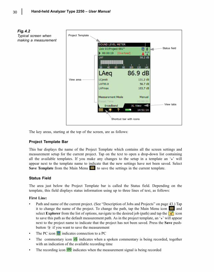
Fig.4.2Typical screen when making a measurement
The key areas, starting at the top of the screen, are as follows:
Project Template Bar
This bar displays the name of the Project Template which contains all the screen settings andmeasurement setup for the current project. Tap on the text to open a drop-down list containingall the available templates. If you make any changes to the setup in a template an �*� willappear next to the template name to indicate that the new settings have not been saved. SelectSave Template from the Main Menu to save the settings in the current template.
Status Field
The area just below the Project Template bar is called the Status field. Depending on thetemplate, this field displays status information using up to three lines of text, as follows:
First Line:� Path and name of the current project. (See �Description of Jobs and Projects� on page 43.) Tap
it to change the name of the project. To change the path, tap the Main Menu icon andselect Explorer from the list of options, navigate to the desired job (path) and tap the iconto save this path as the default measurement path. As in the project template, an �*� will appearnext to the project name to indicate that the project has not been saved. Press the Save push-button if you want to save the measurement
� The PC icon indicates connection to a PC� The commentary icon indicates when a spoken commentary is being recorded, together
with an indication of the available recording time� The recording icon indicates when the measurement signal is being recorded
Project Template
View area
Shortcut bar with icons
Status field
View tabs
CHAPTER 4Getting to Know Your Type 2250 31
� A paperclip icon indicates that a spoken or written comment is attached to the project. Tapthe icon to view, or listen to, the comment
Second Line:� Measurement state represented as icons: Stopped , Running and the Pause icon � Elapsed time of the measurement� Feedback on the action of pressing the following pushbuttons: Reset , Back-erase ,
Start/Pause and Save � Indication that the measurement microphone is uncalibrated. In this case the word Uncal.
appears in the Status Field� Four icons are used to represent whether, or not, the windscreen is fitted and whether you are
measuring in a free-field or diffuse field. For example, no windscreen fitted, measuring in afree-field � ; no windscreen fitted, measuring in a diffuse field � ; windscreen fitted,measuring in a free-field � ; windscreen fitted, measuring in a diffuse field �
� Immediate textual feedback on overload situation and latched overload indicated with an over-load icon
Third Line: Used for Logging, see �Status Field� on page 78.
Central View Area
The Central View Area contains the screens required for a particular measurement, such as bargraphs, result readouts and various frequently used setup parameters (i.e., Meas. mode). Thetemplate defines the content of this area. More than one screen can be used for displaying theinformation. Select the screen using the View Tabs at the bottom of the View area.
Changes made to the screens will only be applied temporarily, i.e., until you select anotherproject template or open another project to re-use the screen from that project. However, if youwant the screen changes to be saved in the current template, select the Save Template optionfrom the Main Menu .
Note: If you make changes to the screen that you do not want to keep, (and you have not yetselected Save Template), you can undo them by selecting the template again from the ProjectTemplate bar at the top of the screen.
Shortcut Bar
The Shortcut Bar, at the bottom of the screen, displays a number of fixed icons that are alwaysaccessible. These include:� Main Menu icon , giving access to the Main Menu. This allows you to navigate to a spe-
cific function, see description earlier under Navigation Principles� Backlight icon , allows you to select a backlight level� Help icon , a quick way to get context-sensitive help from any screen by tapping on the
icon at the bottom. Closing the help window will return you to the previous screen� Battery/power status icon , shows the condition of the battery. All green shows a fully
charged battery, while red means power levels are low. Tap the icon to get more details of the
32 Hand-held Analyzer Type 2250 � User Manual
battery condition. (When the Power Supply lead is connected, the icon will be dis-played in place of the battery icon.)
� The clock in the lower right corner displays the current time. Tap the readout to get details ofthe time and date, or to set the clock
Use of Pushbuttons for Controlling MeasurementsThe design of the Type 2250 is such that the layout of the pushbuttons has been optimised forsingle-handed operation.
Reset PushbuttonUse the Reset pushbutton to reset a measurement, i.e., to reset all detectors, averagers,maximum and minimum hold, etc. If the measurement is paused (i.e., Pause icon is dis-played in the status field), then the measurement reverts to a �stopped� state after a reset, (i.e.,stopped icon displayed with a zeroed readout). If the measurement is running, then themeasurement will be automatically re-started after the reset.
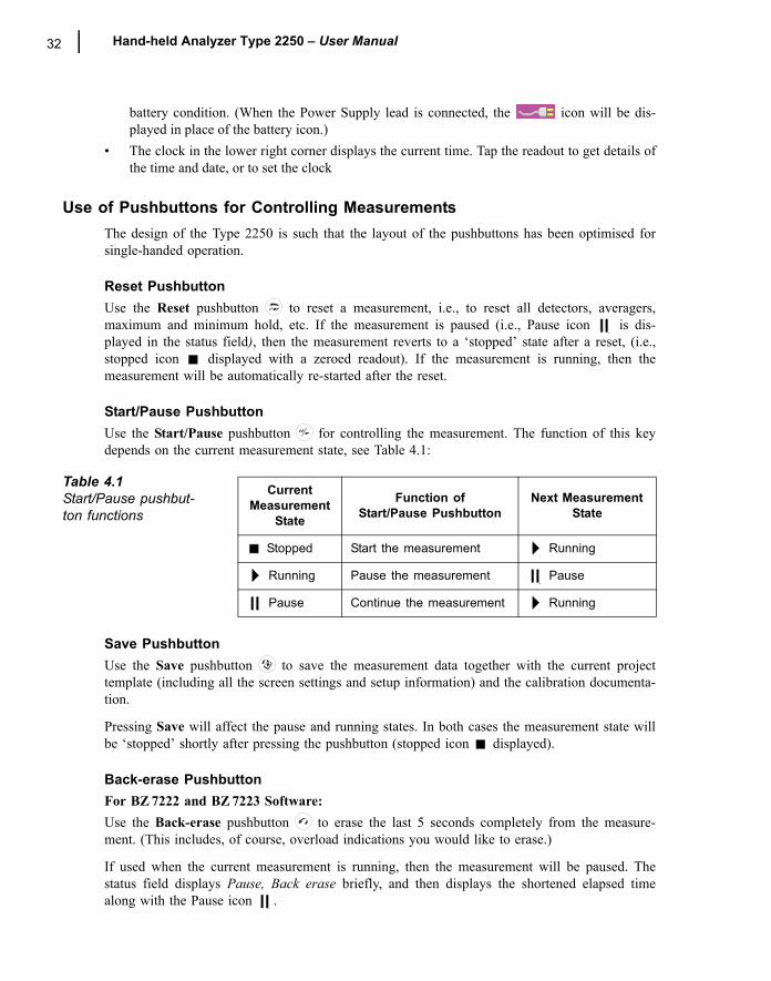
Start/Pause PushbuttonUse the Start/Pause pushbutton for controlling the measurement. The function of this keydepends on the current measurement state, see Table 4.1:
Save PushbuttonUse the Save pushbutton to save the measurement data together with the current projecttemplate (including all the screen settings and setup information) and the calibration documenta-tion.
Pressing Save will affect the pause and running states. In both cases the measurement state willbe �stopped� shortly after pressing the pushbutton (stopped icon displayed).
Back-erase PushbuttonFor BZ 7222 and BZ 7223 Software:Use the Back-erase pushbutton to erase the last 5 seconds completely from the measure-ment. (This includes, of course, overload indications you would like to erase.)
If used when the current measurement is running, then the measurement will be paused. Thestatus field displays Pause, Back erase briefly, and then displays the shortened elapsed timealong with the Pause icon .
Table 4.1Start/Pause pushbut-ton functions
Current Measurement
State
Function of Start/Pause Pushbutton
Next Measurement State
Stopped Start the measurement Running
Running Pause the measurement Pause
Pause Continue the measurement Running
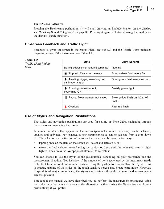
CHAPTER 4Getting to Know Your Type 2250 33
For BZ 7224 Software:Pressing the Back-erase pushbutton will start drawing an Exclude Marker on the display,see �Marking Sound Categories� on page 80. Pressing it again will stop drawing the marker onthe display (toggle function).
On-screen Feedback and Traffic LightFeedback is given on screen in the Status Field, see Fig.4.2, and the Traffic Light indicatesimportant states of the instrument, see Table 4.2:
Use of Stylus and Navigation PushbuttonsThe stylus and navigation pushbuttons are used for setting up Type 2250, navigating throughthe screens and managing the results.
A number of items that appear on the screen (parameter values or icons) can be selected,updated and activated. For instance, a new parameter value can be selected from a drop-downlist. The selection and activation of items on the screen can be done in two ways:� tapping once on the item on the screen will select and activate it, or� move the field selector around using the navigation keys until the item you want is high-
lighted. Then press the Accept pushbutton to activate it
You can choose to use the stylus or the pushbuttons, depending on your preference and themeasurement situation. (For instance, if the amount of noise generated by the instrument needsto be kept to an absolute minimum, consider using the pushbuttons rather than the stylus � thisis because tapping of the stylus on the touch-sensitive screen may create extra noise. However,if speed is of major importance, the stylus can navigate through the setup and measurementscreens quicker.)
Throughout the manual we have described how to perform the measurement procedures usingthe stylus only, but you may also use the alternative method (using the Navigation and Acceptpushbuttons) if you prefer.
Table 4.2Traffic Light Indica-tions
State Light Scheme
During power-on or loading template Nothing
Stopped. Ready to measure Short yellow flash every 5 s
Awaiting trigger, searching for calibration signal
Short green flash every second
Running measurement, everything OK
Steady green light
Pause. Measurement not saved Slow yellow flash on 1/2 s, off 1/2 s
Overload Fast red flash
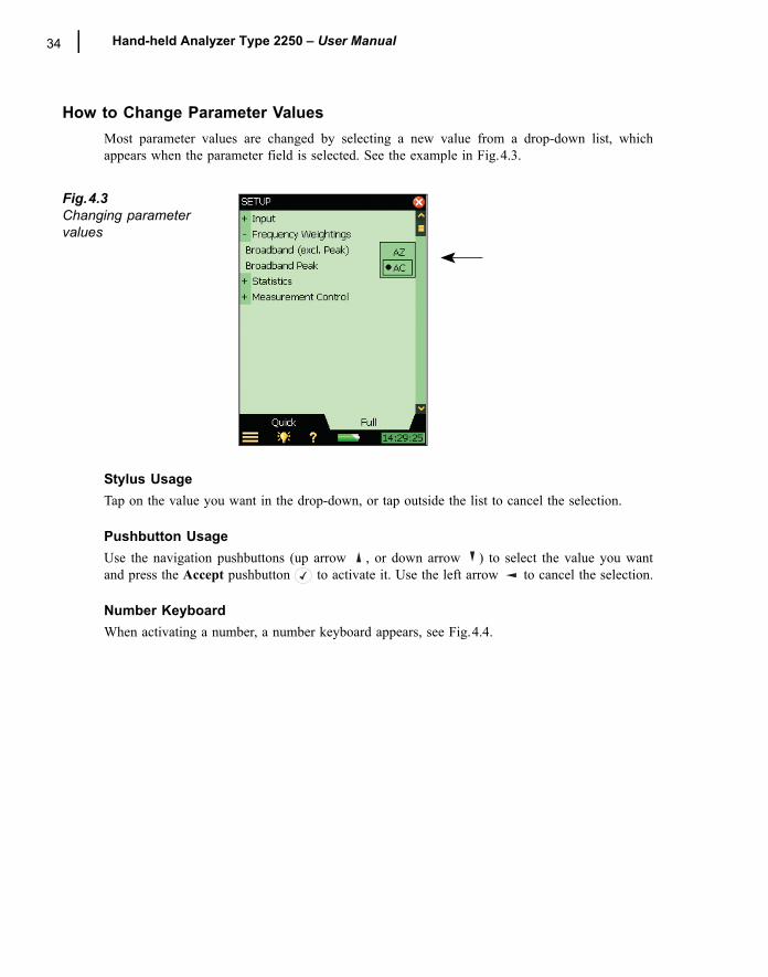
34 Hand-held Analyzer Type 2250 � User Manual
How to Change Parameter ValuesMost parameter values are changed by selecting a new value from a drop-down list, whichappears when the parameter field is selected. See the example in Fig.4.3.
Fig.4.3Changing parameter values
Stylus UsageTap on the value you want in the drop-down, or tap outside the list to cancel the selection.
Pushbutton UsageUse the navigation pushbuttons (up arrow , or down arrow ) to select the value you wantand press the Accept pushbutton to activate it. Use the left arrow to cancel the selection.
Number KeyboardWhen activating a number, a number keyboard appears, see Fig.4.4.
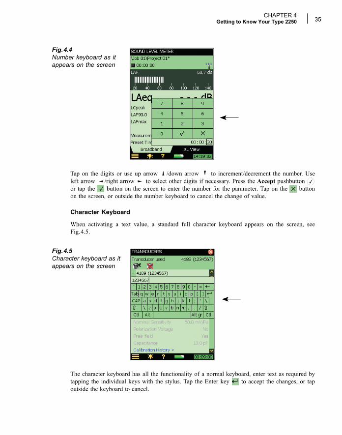
CHAPTER 4Getting to Know Your Type 2250 35
Fig.4.4Number keyboard as it appears on the screen
Tap on the digits or use up arrow /down arrow to increment/decrement the number. Useleft arrow /right arrow to select other digits if necessary. Press the Accept pushbutton or tap the button on the screen to enter the number for the parameter. Tap on the buttonon the screen, or outside the number keyboard to cancel the change of value.
Character Keyboard
When activating a text value, a standard full character keyboard appears on the screen, seeFig.4.5.
Fig.4.5Character keyboard as it appears on the screen
The character keyboard has all the functionality of a normal keyboard, enter text as required bytapping the individual keys with the stylus. Tap the Enter key to accept the changes, or tapoutside the keyboard to cancel.
36 Hand-held Analyzer Type 2250 � User Manual
Locking the Pushbuttons and DisplayThe pushbuttons and display can be locked to prevent inadvertent operation.
To Lock: Select the Lock Keys and Screen option from the Main Menu .
To Unlock: Press the left arrow pushbutton , followed by the right arrow pushbutton ,then the Accept pushbutton .
If you attempt to press a pushbutton, or tap on the screen, while the instrument is locked, aninformation window pops up with instructions on how to unlock it.
37
Chapter 5Calibration
IntroductionCalibration is an adjustment of your sound level meter to measure and display correct values.The sensitivity of the microphone as well as the response of the electronic circuitry can varyslightly over time, or could be affected by environmental conditions such as temperature andhumidity. While you are unlikely to ever experience a large drift or change in sensitivity withType 2250, it is nevertheless good practice to perform regular calibrations, normally before andafter each set of measurements. Often calibration is required by measurement standards, such asIEC 61672-1.
Acoustic CalibrationAcoustic calibration is the preferred calibration method, particularly when standards and regula-tions require calibration before a measurement. The method involves applying an acoustic sig-nal of known magnitude and frequency to the microphone, which calibrates all the instrument�scomponents (microphone, preamplifier and electrical circuitry).
Sound Level CalibratorTo perform the acoustic calibration use Sound Level Calibrator Type 4231. It provides a stablesound pressure at 1 kHz and has minimal susceptibility to environmental factors. The procedureitself is relatively simple, and on Type 2250 the procedure is referred to as the Standard Cali-bration procedure.
The procedure for performing an acoustic calibration and instructions on how to fit the calibra-tor are given in the following section.
Standard Calibration1) Stand away from loud sound sources that may interfere with the calibrator�s signal.
2) Switch on Type 2250 by pressing .
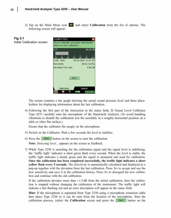
38 Hand-held Analyzer Type 2250 � User Manual
3) Tap on the Main Menu icon and select Calibration from the list of options. Thefollowing screen will appear:
Fig.5.1Initial Calibration screen
The screen contains a bar graph showing the actual sound pressure level and three place-holders for displaying information about the last calibration.
4) Following the first part of the instruction in the status field, fit Sound Level CalibratorType 4231 carefully onto the microphone of the Hand-held Analyzer. (To avoid handlingvibrations to disturb the calibration rest the assembly in a roughly horizontal position on atable or other flat surface.) Ensure that the calibrator fits snugly on the microphone.
5) Switch on the Calibrator. Wait a few seconds the level to stabilise.
6) Press the button on the screen to start the calibration.Note: Detecting level... appears on the screen as feedback.
7) While Type 2250 is searching for the calibration signal and the signal level is stabilising,the �traffic light� indicates a short green flash every second. When the level is stable, thetraffic light indicates a steady green and the signal is measured and used for calibration.Once the calibration has been completed successfully, the traffic light indicates a shortyellow flash every 5 seconds. The Sensitivity is automatically calculated and displayed in apop-up together with the deviation from the last calibration. Press Yes to accept and use thenew sensitivity and save it in the calibration history. Press No to disregard the new calibra-tion and continue with the old calibration.If the calibration deviates more than ±1.5 dB from the initial calibration, then the calibra-tion is stopped without changing the calibration of the instrument. The traffic light willindicate a fast flashing red and an error description will appear in the status field.Hint: If the microphone is separated from Type 2250 using a microphone extension cablethen place Type 2250 so it can be seen from the location of the microphone. Start thecalibration process, (select the Calibration screen and press the button on the
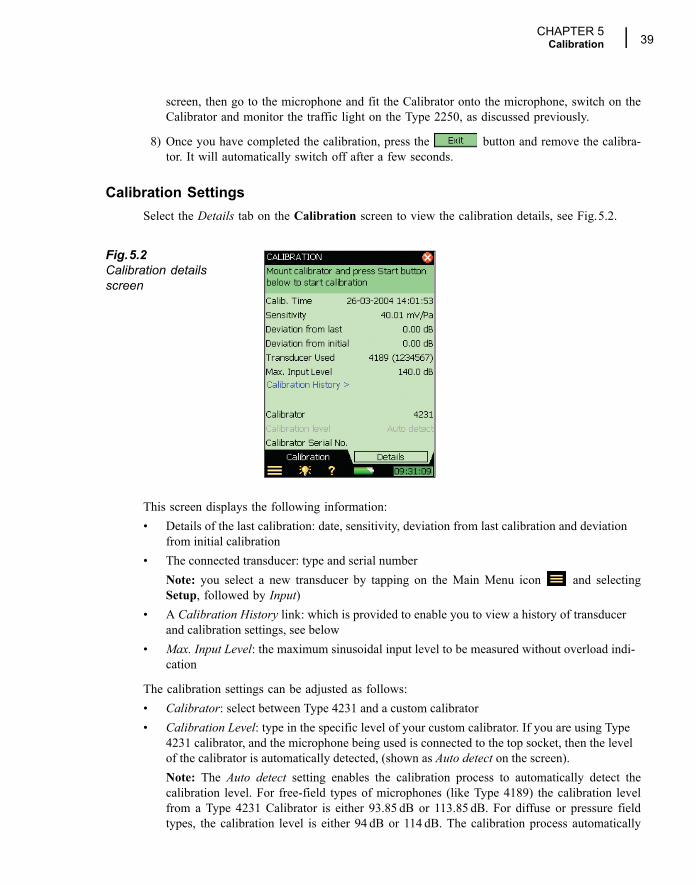
CHAPTER 5Calibration 39
screen, then go to the microphone and fit the Calibrator onto the microphone, switch on theCalibrator and monitor the traffic light on the Type 2250, as discussed previously.
8) Once you have completed the calibration, press the button and remove the calibra-tor. It will automatically switch off after a few seconds.
Calibration SettingsSelect the Details tab on the Calibration screen to view the calibration details, see Fig.5.2.
Fig.5.2Calibration details screen
This screen displays the following information:� Details of the last calibration: date, sensitivity, deviation from last calibration and deviation
from initial calibration� The connected transducer: type and serial number
Note: you select a new transducer by tapping on the Main Menu icon and selectingSetup, followed by Input)
� A Calibration History link: which is provided to enable you to view a history of transducer and calibration settings, see below
� Max. Input Level: the maximum sinusoidal input level to be measured without overload indi-cation
The calibration settings can be adjusted as follows:� Calibrator: select between Type 4231 and a custom calibrator� Calibration Level: type in the specific level of your custom calibrator. If you are using Type
4231 calibrator, and the microphone being used is connected to the top socket, then the level of the calibrator is automatically detected, (shown as Auto detect on the screen).Note: The Auto detect setting enables the calibration process to automatically detect thecalibration level. For free-field types of microphones (like Type 4189) the calibration levelfrom a Type 4231 Calibrator is either 93.85 dB or 113.85 dB. For diffuse or pressure fieldtypes, the calibration level is either 94 dB or 114 dB. The calibration process automatically
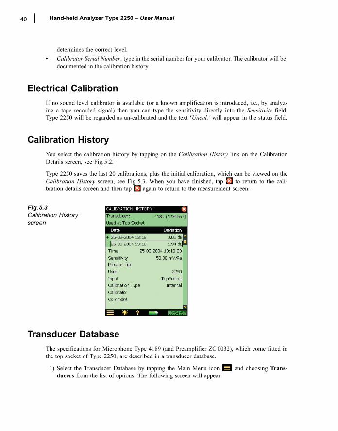
40 Hand-held Analyzer Type 2250 � User Manual
determines the correct level.� Calibrator Serial Number: type in the serial number for your calibrator. The calibrator will be
documented in the calibration history
Electrical CalibrationIf no sound level calibrator is available (or a known amplification is introduced, i.e., by analyz-ing a tape recorded signal) then you can type the sensitivity directly into the Sensitivity field.Type 2250 will be regarded as un-calibrated and the text �Uncal.� will appear in the status field.
Calibration HistoryYou select the calibration history by tapping on the Calibration History link on the CalibrationDetails screen, see Fig.5.2.
Type 2250 saves the last 20 calibrations, plus the initial calibration, which can be viewed on theCalibration History screen, see Fig.5.3. When you have finished, tap to return to the cali-bration details screen and then tap again to return to the measurement screen.
Fig.5.3Calibration History screen
Transducer DatabaseThe specifications for Microphone Type 4189 (and Preamplifier ZC 0032), which come fitted inthe top socket of Type 2250, are described in a transducer database.
1) Select the Transducer Database by tapping the Main Menu icon and choosing Trans-ducers from the list of options. The following screen will appear:
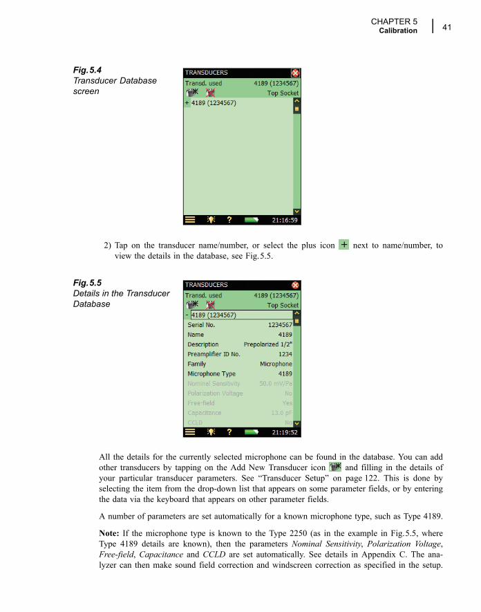
CHAPTER 5Calibration 41
Fig.5.4Transducer Database screen
2) Tap on the transducer name/number, or select the plus icon next to name/number, toview the details in the database, see Fig.5.5.
Fig.5.5Details in the Transducer Database
All the details for the currently selected microphone can be found in the database. You can addother transducers by tapping on the Add New Transducer icon and filling in the details ofyour particular transducer parameters. See �Transducer Setup� on page 122. This is done byselecting the item from the drop-down list that appears on some parameter fields, or by enteringthe data via the keyboard that appears on other parameter fields.
A number of parameters are set automatically for a known microphone type, such as Type 4189.
Note: If the microphone type is known to the Type 2250 (as in the example in Fig.5.5, whereType 4189 details are known), then the parameters Nominal Sensitivity, Polarization Voltage,Free-field, Capacitance and CCLD are set automatically. See details in Appendix C. The ana-lyzer can then make sound field correction and windscreen correction as specified in the setup.
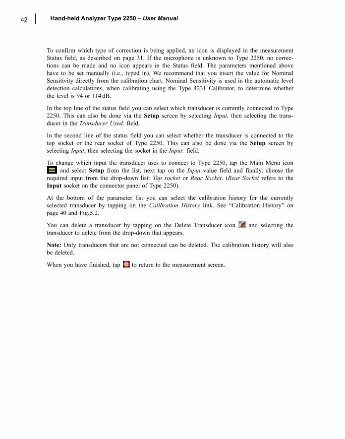
42 Hand-held Analyzer Type 2250 � User Manual
To confirm which type of correction is being applied, an icon is displayed in the measurementStatus field, as described on page 31. If the microphone is unknown to Type 2250, no correc-tions can be made and no icon appears in the Status field. The parameters mentioned abovehave to be set manually (i.e., typed in). We recommend that you insert the value for NominalSensitivity directly from the calibration chart. Nominal Sensitivity is used in the automatic leveldetection calculations, when calibrating using the Type 4231 Calibrator, to determine whetherthe level is 94 or 114 dB.
In the top line of the status field you can select which transducer is currently connected to Type2250. This can also be done via the Setup screen by selecting Input, then selecting the trans-ducer in the Transducer Used: field.
In the second line of the status field you can select whether the transducer is connected to thetop socket or the rear socket of Type 2250. This can also be done via the Setup screen byselecting Input, then selecting the socket in the Input: field.
To change which input the transducer uses to connect to Type 2250, tap the Main Menu icon and select Setup from the list, next tap on the Input value field and finally, choose the
required input from the drop-down list: Top socket or Rear Socket. (Rear Socket refers to theInput socket on the connector panel of Type 2250).
At the bottom of the parameter list you can select the calibration history for the currentlyselected transducer by tapping on the Calibration History link. See �Calibration History� onpage 40 and Fig.5.2.
You can delete a transducer by tapping on the Delete Transducer icon and selecting thetransducer to delete from the drop-down that appears.
Note: Only transducers that are not connected can be deleted. The calibration history will alsobe deleted.
When you have finished, tap to return to the measurement screen.

43
Chapter 6Data Management
Organising Measurements
Description of Jobs and ProjectsWhen saving a set of measurement results, they are organised together with setup information,calibration information, annotations and sound recordings in a project.
A project contains the following :� Measurement results:
� Broadband values (for example, LAeq, LAFmax, LAFmin, etc.)
� Frequency spectra (if Frequency Analysis software BZ 7223 is enabled on your Type 2250 and you have selected a Frequency Analyzer template)
� Measurement Setup � Display Setup (parameters you have selected)� Information on the microphone� Calibration � Annotations � Commentary (attached to measurements as required)� Annotations � Text (attached to measurements as required)� Sound Recordings (attached to measurements as required)
The Project name is automatically created by combining the Project Name Prefix with a number(starting from 001), i.e., Project 001 for the first project, Project 002 for the next, etc.
If preferred, the Project Name Prefix can be changed from the default name of �Project�. To dothis, tap the Main Menu icon , then Preferences followed by Storage Settings to reveal theProject Name Prefix. Tap on the current name to reveal a keyboard for you to type in therequired name.
Projects are saved in folders which are called �jobs� on your Type 2250. These are similar tofolders in the Windows® filing system.
Jobs can be created in the internal memory, on a Secure Digital (SD) Card or on a CompactFlash (CF) Card.
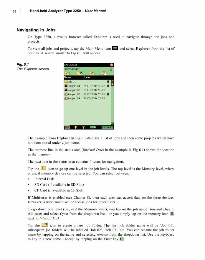
44 Hand-held Analyzer Type 2250 � User Manual
Navigating in JobsOn Type 2250, a results browser called Explorer is used to navigate through the jobs andprojects.
To view all jobs and projects, tap the Main Menu icon and select Explorer from the list ofoptions. A screen similar to Fig.6.1 will appear.
Fig.6.1The Explorer screen
The example from Explorer in Fig.6.1 displays a list of jobs and then some projects which havenot been stored under a job name.
The topmost line in the status area (Internal Disk\ in the example in Fig.6.1) shows the locationin the memory.
The next line in the status area contains 4 icons for navigation.
Tap the icon to go up one level in the job-levels. The top level is the Memory level, wherephysical memory devices can be selected. You can select between:� Internal Disk� SD Card (if available in SD Slot)� CF Card (if available in CF Slot)
If Multi-user is enabled (see Chapter 8), then each user can access data on the three devices.However, a user cannot see or access jobs for other users.
To go down one level (i.e., exit the Memory level), you tap on the job name (Internal Disk inthis case) and select Open from the dropdown list - or you simply tap on the memory icon next to Internal Disk.
Tap the icon to create a new job folder. The first job folder name will be �Job 01�,subsequent job folders will be labelled �Job 02�, �Job 03�, etc. You can rename the job foldername by tapping on the name and selecting rename from the dropdown list. Use the keyboardto key in a new name � accept by tapping on the Enter key .
CHAPTER 6Data Management 45
To go down one level (open a job), you tap on the job name in the list and select Open fromthe dropdown list � or you simply tap on the job icon to the left of the job name.
You can move a job/project (and its content) to another job by tapping the job name/projectname and selecting Cut from the dropdown list. Then navigate to the job you want as the newholder of the moved job/project and tap on the Paste icon , or navigate to the level aboveand tap on the job name and select paste from the dropdown list.
In order to copy a job/project do as described above, but use Copy instead of Cut from thedropdown list.
Select Delete from the dropdown list in order to delete the job/project and all of its contents.
Selecting Default Measurement Job/PathTap the icon to select the current job as the default measurement job, where all projectswill be saved when you press the Save pushbutton. The job name, followed by the currentproject name, will appear in the topmost line in the status area to confirm which job you haveselected.
Recalling MeasurementsYou can recall your measurement results in one of two ways:� To display the measured results (and calibration details) only, use the results viewer � this can
be done during an ongoing measurement and is a convenient way of browsing several sets of measurement data, see below
� To re-use setups from previously saved projects, use the Open command in Explorer � this will recall the project template (display settings and measurement setup used on the saved results) along with the results. This will, however, stop and reset the current measurement
Viewing DataUse Explorer to locate the project with the results you want to view, then tap on the projectname and select View from the dropdown that appears (or simply tap on the project icon). Thiswill open the Viewer (Fig.6.2).
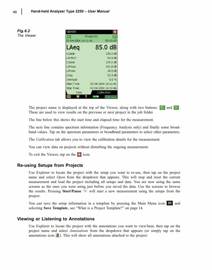
46 Hand-held Analyzer Type 2250 � User Manual
Fig.6.2The Viewer
The project name is displayed at the top of the Viewer, along with two buttons: and .These are used to view results on the previous or next project in the job folder.
The line below this shows the start time and elapsed time for the measurement.
The next line contains spectrum information (Frequency Analysis only) and finally some broad-band values. Tap on the spectrum parameters or broadband parameters to select other parameters.
The Calibration tab allows you to view the calibration details for the measurement.
You can view data on projects without disturbing the ongoing measurement.
To exit the Viewer, tap on the icon.
Re-using Setups from ProjectsUse Explorer to locate the project with the setup you want to re-use, then tap on the projectname and select Open from the dropdown that appears. This will stop and reset the currentmeasurement and load the project including all setups and data. You are now using the samescreens as the ones you were using just before you saved the data. Use the screens to browsethe results. Pressing Start/Pause will start a new measurement using the setups from theproject.
You can save the setup information in a template by pressing the Main Menu icon andselecting Save Template, see �What is a Project Template?� on page 14.
Viewing or Listening to AnnotationsUse Explorer to locate the project with the annotations you want to view/hear, then tap on theproject name and select Annotations from the dropdown that appears (or simply tap on theannotations icon ). This will show all annotations attached to the project:
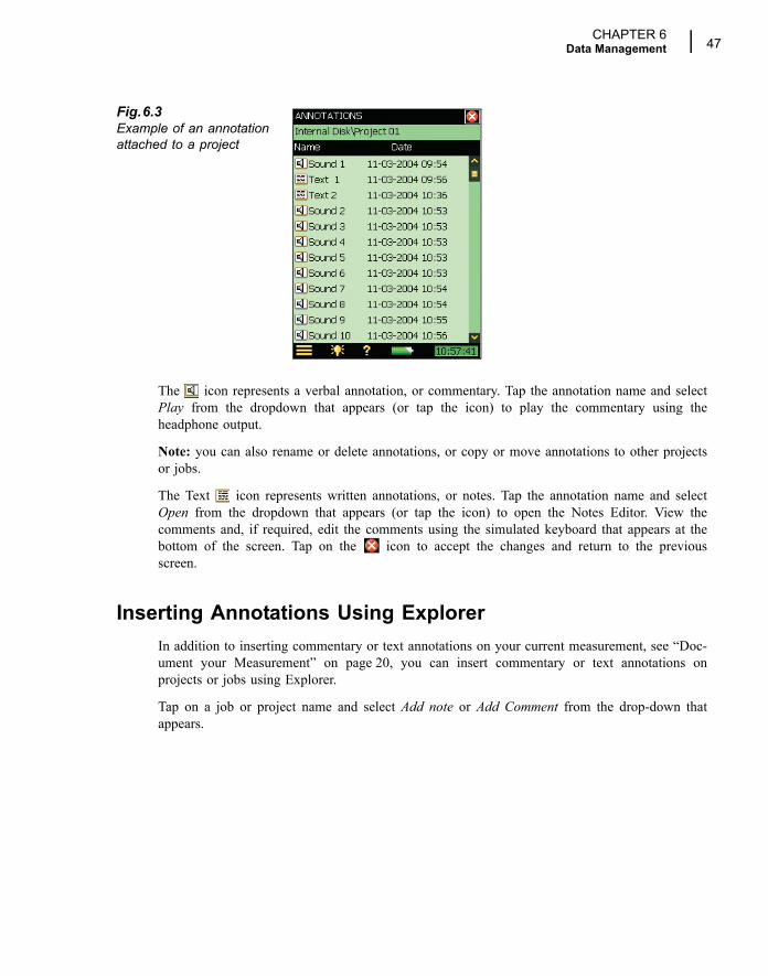
CHAPTER 6Data Management 47
Fig.6.3Example of an annotation attached to a project
The icon represents a verbal annotation, or commentary. Tap the annotation name and selectPlay from the dropdown that appears (or tap the icon) to play the commentary using theheadphone output.
Note: you can also rename or delete annotations, or copy or move annotations to other projectsor jobs.
The Text icon represents written annotations, or notes. Tap the annotation name and selectOpen from the dropdown that appears (or tap the icon) to open the Notes Editor. View thecomments and, if required, edit the comments using the simulated keyboard that appears at thebottom of the screen. Tap on the icon to accept the changes and return to the previousscreen.
Inserting Annotations Using ExplorerIn addition to inserting commentary or text annotations on your current measurement, see �Doc-ument your Measurement� on page 20, you can insert commentary or text annotations onprojects or jobs using Explorer.
Tap on a job or project name and select Add note or Add Comment from the drop-down thatappears.

48 Hand-held Analyzer Type 2250 � User Manual
49
Chapter 7Transferring Data to Your PC, Post-processing
and Reporting
Transferring Measurement Data to Your PCUtility Software for Hand-held Analyzers BZ 5503 is used for all communication between yourPC and Type 2250. Connect Type 2250 to your PC using the supplied USB cable AO 1476 orusing a modem connection (see Chapter 8).
Use this software to:� Transfer measurement data and templates from Type 2250 to your PC, and vice versa� Organise data on Type 2250 � Create users on Type 2250� Upgrade software on Type 2250� Install software licenses on Type 2250
Using this software, measurements on Type 2250 can be controlled from your PC and displayedon-line, using the same user interface on the PC as on Type 2250.
Data transferred to the PC are organised in Archives.
View the measurement data in the Archives or edit the project templates.
Data in the archives can be exported to:� Noise Explorer Type 7815 � Evaluator Type 7820� Protector Type 7825� Predictor Type 7810� Lima Type 7812� Acoustic Determinator Type 7816
� Microsoft® Excel for further post-processing and reporting
Sound Recordings can be input to the Brüel & Kjær PULSE� Analyzer Platform for furtheranalysis � please contact your local Brüel & Kjær representative for further information.
50 Hand-held Analyzer Type 2250 � User Manual
Post-processing and ReportingThe software modules are further enhanced by Brüel & Kjær�s post-processing software suite,including Utility Software for Hand-held Analyzers BZ 5503 for data transfer, setup and remotedisplay (included with your Type 2250), Noise Explorer Type 7815 for viewing data, EvaluatorType 7820 for assessing environmental noise and Protector Type 7825 for assessing workplacenoise.
For further information, please refer to the on-line help included with the relevant PC Software.This software is supplied on the Environmental Software CD-ROM (BZ 5298), which is includ-ed with your Type 2250.
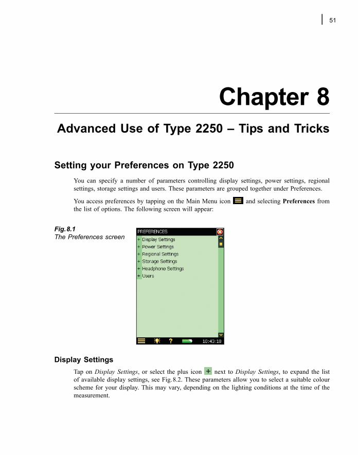
51
Chapter 8Advanced Use of Type 2250 � Tips and Tricks
Setting your Preferences on Type 2250You can specify a number of parameters controlling display settings, power settings, regionalsettings, storage settings and users. These parameters are grouped together under Preferences.
You access preferences by tapping on the Main Menu icon and selecting Preferences fromthe list of options. The following screen will appear:
Fig.8.1The Preferences screen
Display SettingsTap on Display Settings, or select the plus icon next to Display Settings, to expand the listof available display settings, see Fig.8.2. These parameters allow you to select a suitable colourscheme for your display. This may vary, depending on the lighting conditions at the time of themeasurement.
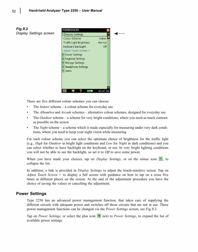
52 Hand-held Analyzer Type 2250 � User Manual
Fig.8.2Display Settings screen
There are five different colour schemes you can choose:� The Indoor scheme � a colour scheme for everyday use� The Alhambra and Arcade schemes � alternative colour schemes, designed for everyday use� The Outdoor scheme � a scheme for very bright conditions, where you need as much contrast
as possible on the screen� The Night scheme � a scheme which is made especially for measuring under very dark condi-
tions, where you need to keep your night vision while measuring
For each colour scheme you can select the optimum choice of brightness for the traffic light(e.g., High for Outdoor in bright light conditions and Low for Night in dark conditions) and youcan select whether to have backlight on the keyboard, or not. In very bright lighting conditionsyou will not be able to see the backlight, so set it to Off to save some power.
When you have made your choices, tap on Display Settings, or on the minus icon , tocollapse the list.
In addition, a link is provided in Display Settings to adjust the touch-sensitive screen. Tap onAdjust Touch Screen > to display a full screen with guidance on how to tap on a cross fivetimes at different places on the screen. At the end of the adjustment procedure you have thechoice of saving the values or cancelling the adjustment.
Power SettingsType 2250 has an advanced power management function, that takes care of supplying thedifferent circuits with adequate power and switches off those circuits that are not in use. Thesepower management functions can be changed via the Power Settings screen, see Fig.8.3.
Tap on Power Settings, or select the plus icon next to Power Settings, to expand the list ofavailable power settings.
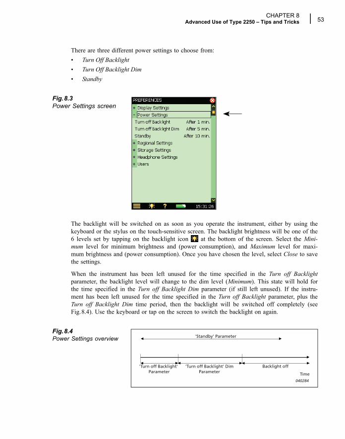
CHAPTER 8Advanced Use of Type 2250 � Tips and Tricks 53
There are three different power settings to choose from:� Turn Off Backlight� Turn Off Backlight Dim� Standby
Fig.8.3Power Settings screen
The backlight will be switched on as soon as you operate the instrument, either by using thekeyboard or the stylus on the touch-sensitive screen. The backlight brightness will be one of the6 levels set by tapping on the backlight icon at the bottom of the screen. Select the Mini-mum level for minimum brightness and (power consumption), and Maximum level for maxi-mum brightness and (power consumption). Once you have chosen the level, select Close to savethe settings.
When the instrument has been left unused for the time specified in the Turn off Backlightparameter, the backlight level will change to the dim level (Minimum). This state will hold forthe time specified in the Turn off Backlight Dim parameter (if still left unused). If the instru-ment has been left unused for the time specified in the Turn off Backlight parameter, plus theTurn off Backlight Dim time period, then the backlight will be switched off completely (seeFig.8.4). Use the keyboard or tap on the screen to switch the backlight on again.
Fig.8.4Power Settings overview
'Turn off Backlight' Parameter
'Turn off Backlight' DimParameter
Backlight off
Time
'Standby' Parameter
040284
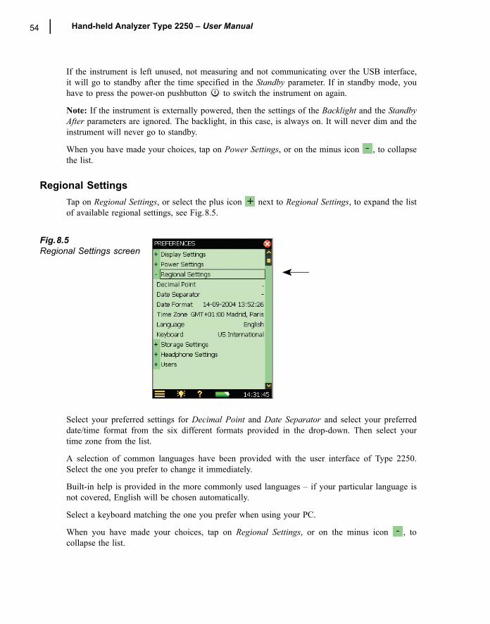
54 Hand-held Analyzer Type 2250 � User Manual
If the instrument is left unused, not measuring and not communicating over the USB interface,it will go to standby after the time specified in the Standby parameter. If in standby mode, youhave to press the power-on pushbutton to switch the instrument on again.
Note: If the instrument is externally powered, then the settings of the Backlight and the StandbyAfter parameters are ignored. The backlight, in this case, is always on. It will never dim and theinstrument will never go to standby.
When you have made your choices, tap on Power Settings, or on the minus icon , to collapsethe list.
Regional SettingsTap on Regional Settings, or select the plus icon next to Regional Settings, to expand the listof available regional settings, see Fig.8.5.
Fig.8.5Regional Settings screen
Select your preferred settings for Decimal Point and Date Separator and select your preferreddate/time format from the six different formats provided in the drop-down. Then select yourtime zone from the list.
A selection of common languages have been provided with the user interface of Type 2250.Select the one you prefer to change it immediately.
Built-in help is provided in the more commonly used languages � if your particular language isnot covered, English will be chosen automatically.
Select a keyboard matching the one you prefer when using your PC.
When you have made your choices, tap on Regional Settings, or on the minus icon , tocollapse the list.
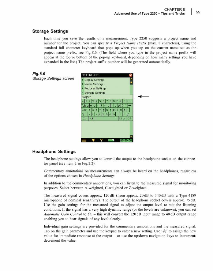
CHAPTER 8Advanced Use of Type 2250 � Tips and Tricks 55
Storage SettingsEach time you save the results of a measurement, Type 2250 suggests a project name andnumber for the project. You can specify a Project Name Prefix (max. 8 characters), using thestandard full character keyboard that pops up when you tap on the current name set as theproject name prefix, see Fig.8.6. (The field where you type in the project name prefix willappear at the top or bottom of the pop-up keyboard, depending on how many settings you haveexpanded in the list.) The project suffix number will be generated automatically.
Fig.8.6Storage Settings screen
Headphone SettingsThe headphone settings allow you to control the output to the headphone socket on the connec-tor panel (see item 2 in Fig.2.2).
Commentary annotations on measurements can always be heard on the headphones, regardlessof the options chosen in Headphone Settings.
In addition to the commentary annotations, you can listen to the measured signal for monitoringpurposes. Select between A-weighted, C-weighted or Z-weighted.
The measured signal covers approx. 120 dB (from approx. 20 dB to 140 dB with a Type 4189microphone of nominal sensitivity). The output of the headphone socket covers approx. 75 dB.Use the gain settings for the measured signal to adjust the output level to suit the listeningconditions. If the signal has a very high dynamic range (or the levels are unknown), you can setAutomatic Gain Control to On � this will convert the 120 dB input range to 40 dB output rangeenabling you to hear signals of any level clearly.
Individual gain settings are provided for the commentary annotations and the measured signal.Tap on the gain parameter and use the keypad to enter a new setting. Use �@� to assign the newvalue for immediate response at the output � or use the up/down navigation keys to increment/decrement the value.
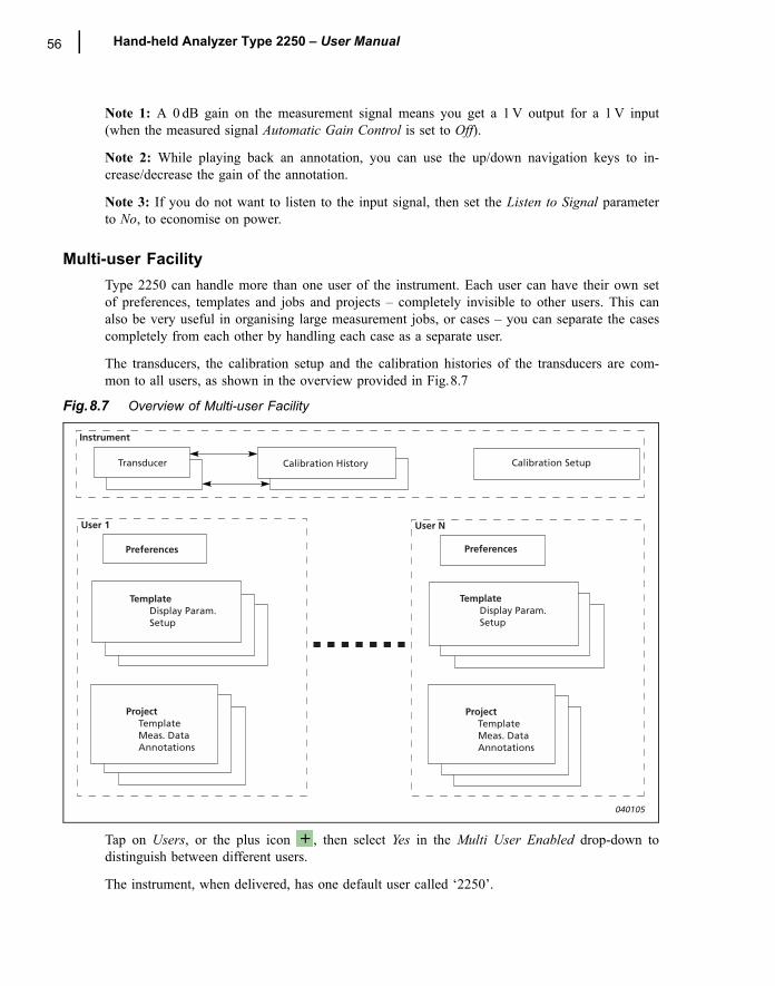
56 Hand-held Analyzer Type 2250 � User Manual
Note 1: A 0 dB gain on the measurement signal means you get a 1 V output for a 1 V input(when the measured signal Automatic Gain Control is set to Off).
Note 2: While playing back an annotation, you can use the up/down navigation keys to in-crease/decrease the gain of the annotation.
Note 3: If you do not want to listen to the input signal, then set the Listen to Signal parameterto No, to economise on power.
Multi-user FacilityType 2250 can handle more than one user of the instrument. Each user can have their own setof preferences, templates and jobs and projects � completely invisible to other users. This canalso be very useful in organising large measurement jobs, or cases � you can separate the casescompletely from each other by handling each case as a separate user.
The transducers, the calibration setup and the calibration histories of the transducers are com-mon to all users, as shown in the overview provided in Fig.8.7
Fig.8.7 Overview of Multi-user Facility
Tap on Users, or the plus icon , then select Yes in the Multi User Enabled drop-down todistinguish between different users.
The instrument, when delivered, has one default user called �2250�.
Transducer Calibration History Calibration Setup
Instrument
User 1 User N
Preferences
TemplateDisplay Param.Setup
ProjectTemplateMeas. DataAnnotations
Preferences
TemplateDisplay Param.Setup
ProjectTemplateMeas. DataAnnotations
040105
CHAPTER 8Advanced Use of Type 2250 � Tips and Tricks 57
You require Utility software for Hand-held Analyzers BZ 5503 (included with Type 2250) to setup new users on the instrument, see �Transferring Measurement Data to Your PC� on page 49.
Printer SettingsYou can make screen dumps on a printer connected to Type 2250 using USB cable AO 0657.Use the Printer Settings to select your preferred printer.
When a printer has been selected under the Printer Used parameter, then the Print Screencommand in the Main Menu appears. Use this command to print a screen dump of any screenon Type 2250.
The printer must either be an MPS type, or accept the PCL® printer language (PCL: PrinterControl Language developed by Hewlett-Packard � see details on their website: www.hp.com):� MPS: Mobile Pro Spectrum thermal printer from AM-TECH, see details on website:
www.amteq.co.kr� PCL: printers accepting PCL printer language � PCL Inkjet: suitable for Inkjet printers and supports colour printing� PCL Laser: suitable for Laser printers
For the PCL printers you can use the Top and Left Margin parameters to position the print onthe paper, and use Width and Height parameters to set the size of the print.
Modem SettingsYou can use Type 2250 for monitoring in remote places and control it using Utility Software forHand-held Analyzers BZ 5503 via a telephone connection � wired or wireless � using suitablemodems. When you connect via modem you will see the contents of Type 2250 in the Instru-ment Task, as if you had made the connection via USB. You then have the same possibilitiesfor transferring data to the Archive and organising data on Type 2250, as if you were connectedvia the USB connector. Please refer to the on-line manual of BZ 5503 for details of how tomake a connection and dial-up.
Hayes compatible modems (GSM or standard analogue modems) are supported. The modemconnected to Type 2250 should either be a Compact Flash modem, or a modem with an RS-232serial interface, to be connected via a Compact Flash to Serial converter.
To use the modem you only need to set the Modem parameter to Enabled in the ModemSettings. No other settings are necessary.
Note: Before you connect or disconnect a modem (or switch it on or off), the Modem parametershould be set to Disabled, or Type 2250 must be in standby mode or switched completely off �the latter is recommended.
Compact Flash Modems
Compact flash modems can be inserted directly in the compact flash socket of Type 2250 (seeitem 9 in Fig.2.2).
58 Hand-held Analyzer Type 2250 � User Manual
Analogue Modems
The following modems have been tested: � CF 56 K Modem Card from Socket � see details on website: www.socketcom.com� 56 K CompactModem from Pretec � see details on website: www.pretec.com
GSM Modems
The following modems have been tested: � CONNECT2AIR GPRS Compact Flash Card from Fujitsu-Siemens � see details on website:
www.fujitsu-siemens.com� CompactGPRS from Pretec � see details on website: www.pretec.com
Note: The SIM card should be usable without pin-code.
Modems with RS-232 Serial interfaces
Modems with an RS-232 serial interface can be connected using a Compact Flash to Serialconverter inserted in the compact flash slot of Type 2250. The following Compact Flash toSerial converter has been tested:� Serial I/O CF Card � Ruggedized, from Socket � see details on website: www.socketcom.com
Analogue Modems
The following modem has been tested: � MT5600ZDXe from MultiTech Systems (Brüel & Kjær order number: ZM 0069) � see details
on website: www.multitech.com
GSM Modems
The following modems have been tested: � GSM Module M1 from Siemens� WMOD2B-G900/1800 Dual Band Modem from Wavecom (Brüel & Kjær order number:
WQ 1238) � see details on website: www.wavecom.com
Note: The SIM card should be usable without pin-code.
Preparing your MeasurementsYou can prepare your measurements in advance by making job folders, setting up the correctmeasurement parameters in the templates, and by making checklists (see example in Fig.8.8)either as memos containing addresses and phone numbers of relevant people, or notes that havebeen partly filled-in beforehand, where you just have to fill in the final information on location.The notes can be attached to jobs as annotations, and can be copied onto projects, when neces-sary.
When you have finished typing in your note, tap on the icon to accept the changes and saveit as a text annotation. See �Document your Measurement� on page 20 for more details onannotations.
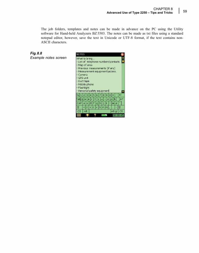
CHAPTER 8Advanced Use of Type 2250 � Tips and Tricks 59
The job folders, templates and notes can be made in advance on the PC using the Utilitysoftware for Hand-held Analyzers BZ 5503. The notes can be made as txt files using a standardnotepad editor, however, save the text in Unicode or UTF-8 format, if the text contains non-ASCII characters.
Fig.8.8Example notes screen

60 Hand-held Analyzer Type 2250 � User Manual
61
Chapter 9Installing, Updating and Upgrading
Applications
How to Install New Applications2250 Sound Level Meter Software BZ 7222, 2250 Frequency Analysis Software BZ 7223, 2250Logging Software BZ 7224 and 2250 Sound Recording Option BZ 7226 are pre-installed onType 2250. However, a valid license is required to run the software. If you have purchasedType 2250 together with the software application(s), then the relevant license(s) will come pre-installed on the instrument.
If you purchase a separate software application for your Type 2250, then you have to install thelicense on the instrument. This is done using Utility Software for Hand-held Analyzers,BZ 5503, please consult the on-line help included with the BZ 5503 software for instructions onhow to install a license.
Tap on the Help icon on the instrument�s screen, then select About to get a list of installedsoftware and licenses.
How to Update/Upgrade ApplicationsWhen new versions of Type 2250 software become available, you may want to install thesoftware on your instrument. This is done using the Utility Software for Hand-held Analyzers,BZ 5503. Some software versions will be free updates, and some will be upgrades requiring thata new license is purchased. The BZ 5503 software will clearly indicate if the new softwareversion is an update (free of charge) or an upgrade (license fee). Please consult the on-line helpincluded with the BZ 5503 software for instructions on how to install upgrades/updates of thesoftware.
Tap on the Help icon on the instrument�s screen, then select About to get a list of installedsoftware and licenses.
62 Hand-held Analyzer Type 2250 � User Manual
How to Move a LicenseIf you have more than one Type 2250, you may want to share application software between theinstruments. You can do this by moving the license from one Type 2250 to another by usingUtility Software for Hand-held Analyzers BZ 5503, together with the License Mover VP 0647.
If you lend out your Type 2250, you may want to temporarily �un-install� applications notneeded. This can be achieved by moving the license of the application to License MoverVP 0647. When needed again, you move the license back to your Type 2250.
Please consult the on-line help included with the BZ 5503 software for instructions on how tomove a license.
Troubleshooting
Type 2250 MeasurementsIf your Type 2250 measurement seems to be wrong, then:� Check the cabling, if any� Check that the microphone, including preamplifier, is correctly mounted in the top socket (or
correctly connected to the extension cable)� Check that the Input parameter is set to Top Socket/Rear Socket in agreement with how you are
going to use the input. This is found by tapping the Main Menu icon , then Setup, fol-lowed by Input
� Check that the transducer you have mounted on your Type 2250 is selected as the Transducer Used parameter, this is also found in the Setup menu
� Check whether the parameters for the selected transducer (Transducer Used) are set correctly, especially the Microphone Type and Polarization Voltage parameters. These are found by tap-ping the Main Menu icon , then Transducers
� Check that the Sound Field and Windscreen Correction parameters have been set correctly. These are found by tapping the Main Menu icon , then Setup, followed by Input
� Check if the calibration is OK (make a new calibration using an external calibrator)
SD and CF CardsThe Logging and Sound Recording software requires that measurements are saved on SD or CFmemory cards. If you experience problems in storing or recalling data on memory cards, youcan check and repair the integrity of the file system on the memory card or even re-format it,by doing the following:
1) Insert the memory card in the correct slot of the connector panel of Type 2250, see Fig.2.2.
2) Tap the Main Menu icon and then Explorer.
3) Tap on the icon to go up folder levels until you have reached the topmost level with alist of the available memory devices.
CHAPTER 9Installing, Updating and Upgrading Applications 63
4) Tap on the name of the memory card (not the icon) to get a list of available commands.
5) Select Check and Repair to start the procedure. If any errors are found in the file system,they are fixed. When finished, you will be informed whether the memory device was OKor that errors have been fixed.Note: the checking procedure can take several minutes, depending on the size of the mem-ory card.
Formatting a memory card:
1) Select Format to start the formatting procedure.
WARNING: All data on the memory card will be erased during the formatting process.Note: the formatting procedure can take several minutes � depending on the size of thememory card.
WARNING: Do not remove the memory card or switch off the instrument during theprocedure � this might damage the file system and data and make the card unusable.
Battery Pack and Recalibration of Battery Charge IndicatorThe software keeps the capacity of the battery pack updated. Over time the total capacity of thebattery pack decreases. If you find that the �Time Remaining� estimate (tap on the battery icon
to get this information) does not match the real time remaining (e.g., the instrumentswitches off automatically because of lack of power while the Time Remaining estimate indi-cates at least ½ hour), then you should manually re-calibrate the capacity of the battery pack.This is done using the following method:� Drain all the power from the battery:
� Switch the instrument on� Disconnect external power � Disconnect the instrument from the PC � In the Preferences menu, under Power Settings, set Standby After to Never � You may want to set Backlight On to Always (in the same menu) and select the maximum
level of display backlight in order to drain the battery faster (use the Backlight icon at the bottom of the screen)
� Leave the instrument until the battery voltage becomes so low that the instrument switches itself off
� Charge the battery fully (at least 10 hours):� Connect the Mains Power Supply ZG 0426 to the instrument� Switch the instrument on (and leave it on) and remember to reset the Standby After and
Backlight On to your preferred settings� Let the battery charge until the battery charge indicator just below the power socket starts
flashing
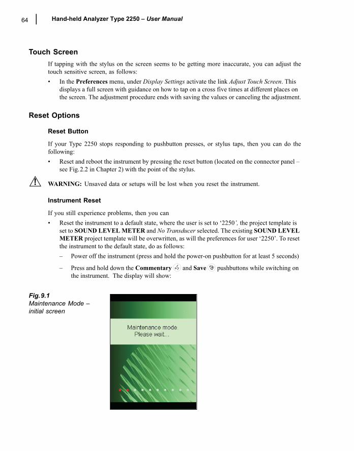
64 Hand-held Analyzer Type 2250 � User Manual
Touch ScreenIf tapping with the stylus on the screen seems to be getting more inaccurate, you can adjust thetouch sensitive screen, as follows:� In the Preferences menu, under Display Settings activate the link Adjust Touch Screen. This
displays a full screen with guidance on how to tap on a cross five times at different places on the screen. The adjustment procedure ends with saving the values or canceling the adjustment.
Reset Options
Reset Button
If your Type 2250 stops responding to pushbutton presses, or stylus taps, then you can do thefollowing: � Reset and reboot the instrument by pressing the reset button (located on the connector panel �
see Fig.2.2 in Chapter 2) with the point of the stylus.
WARNING: Unsaved data or setups will be lost when you reset the instrument.
Instrument Reset
If you still experience problems, then you can � Reset the instrument to a default state, where the user is set to �2250�, the project template is
set to SOUND LEVEL METER and No Transducer selected. The existing SOUND LEVEL METER project template will be overwritten, as will the preferences for user �2250�. To reset the instrument to the default state, do as follows:� Power off the instrument (press and hold the power-on pushbutton for at least 5 seconds)
� Press and hold down the Commentary and Save pushbuttons while switching on the instrument. The display will show:
Fig.9.1Maintenance Mode �initial screen
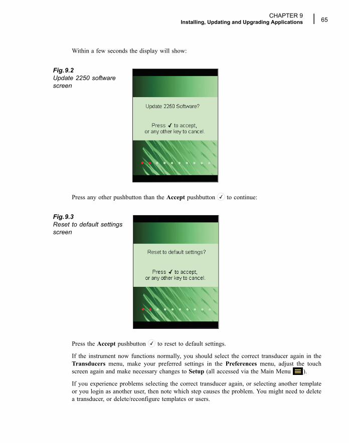
CHAPTER 9Installing, Updating and Upgrading Applications 65
Within a few seconds the display will show:
Fig.9.2Update 2250 software screen
Press any other pushbutton than the Accept pushbutton to continue:
Fig.9.3Reset to default settings screen
Press the Accept pushbutton to reset to default settings.
If the instrument now functions normally, you should select the correct transducer again in theTransducers menu, make your preferred settings in the Preferences menu, adjust the touchscreen again and make necessary changes to Setup (all accessed via the Main Menu ).
If you experience problems selecting the correct transducer again, or selecting another templateor you login as another user, then note which step causes the problem. You might need to deletea transducer, or delete/reconfigure templates or users.
66 Hand-held Analyzer Type 2250 � User Manual
WARNING: If you delete a transducer, the calibration history will be lost.
You can delete a transducer from the transducer database by pressing the Delete Transducericon (see �Transducer Database� on page 40).
To delete/reconfigure templates or users you can use Utility Software for Hand-held AnalyzersBZ 5503, with the instrument connected to the PC using the USB interface cable (AO 1476) ora modem connection. Please consult the on-line help included with the BZ 5503 software forinstructions on how to configure Type 2250.
Re-installing Software
If the instrument still does not work normally after performing the �Reset to Default Settings�procedure, then the software might need to be re-installed. This can be done in two ways:
1) If the connection to Utility Software for Hand-held Analyzers BZ 5503 works with theinstrument connected to the PC using a USB cable, then the software can be re-installedand re-configured through the USB cable. Please consult the on-line help included with theBZ 5503 software for instructions on how to re-install software on Type 2250.
2) If the connection to the PC does not work, then you need a Compact Flash card (size atleast 64 Mbytes) and a Compact Flash card reader for the PC. You can then use UtilitySoftware for Hand-held Analyzers BZ 5503 to update the Compact Flash card with thenecessary files. Please consult the on-line help included with the BZ 5503 software forinstructions on how to update a Compact Flash card with installation files for Type 2250. Power off Type 2250 and insert the compact flash card in the CF slot on the instrument.Then press and hold down the Commentary and Save pushbuttons while switchingon the instrument. The Maintenance Mode initial screen will be displayed, and then withina few seconds the screen shown in Fig.9.2 will appear.Press the Accept pushbutton to update the software. This will take approx. 5 minutes.
WARNING: Do not remove the CF-card while updating the Type 2250 software!
When the Type 2250 software has been updated, you will get the option of resetting to thedefault settings.
If the problem still persists, then you should contact your local Brüel & Kjær representative.
Service and RepairType 2250 is designed and constructed to provide many years of reliable operation. However, ifa fault occurs that impairs the sound level meter�s correct function, then remove the batterypack and disconnect any external power supply to prevent risk of further damage.
For more information about preventing faults or damage to your sound level meter, please readthe �Care, Cleaning and Storage� section that follows.
For repair, contact your local Brüel & Kjær representative. Brüel & Kjær provides a high level ofsupport and after-sales service to assist customers in the handling and operation of their instru-ments.
CHAPTER 9Installing, Updating and Upgrading Applications 67
Care, Cleaning and StorageType 2250 is a delicate precision instrument. When handling, storing or cleaning your instru-ment, please take the following precautions.
Handling the Instrument� Do not try to remove the microphone grid as you can easily damage the microphone in this
way� Do not attempt to open the instrument. There are no user-serviceable parts inside. If you think
your instrument requires service, please contact your Brüel & Kjær representative� Do not allow the instrument to get wet� Protect the instrument from impact. Do not drop it. Transport it in the supplied carrying pouch
Cleaning the InstrumentIf the instrument casing becomes dirty, then wipe it with a lightly dampened cloth. Do not useabrasive cleansers or solvents. Do not allow moisture to enter the microphone, connectors orcasing.
Storing the Instrument� Keep the sound level meter in a dry place, preferably within its carrying pouch� For long-term storage, remove the battery pack� Do not exceed storage temperature limits of �25 to +70°C (�13 to +158°F)

68 Hand-held Analyzer Type 2250 � User Manual
69
Chapter 101/1- or 1/3-octave Frequency Analysis
(Optional Module)
2250 Frequency Analysis Software BZ 7223 enables you to make 1/1-octave or 1/3-octavemeasurements and broadband sound level measurements simultaneously.
Check the About Menu to see whether you have the right license to run the frequency analyzer.The About Menu is accessed from the built-in help � tap on the shortcut bar, then selectAbout. See Chapter 9 for instructions on installing the license for the frequency analyzer.
Setting up the InstrumentThe frequency analyzer measures the following spectra parameters during timed measurement:� LXeq
� LXFmax
� LXSmax
� LXFmin
� LXSmin
where X is the frequency weighting A, C or Z.
These spectra are saved in the project together with the measured sound level meter (broad-band) parameters.
In addition, the instantaneous spectra LXF and LXS are always available.
1) Select the FREQUENCY ANALYZER Project Template. (See �What is a Project Tem-plate?� on page 14 for more details on templates.) The Project Template is displayed at thetop of the screen, if it does not display FREQUENCY ANALYZER, tap on the black barat the top of the screen and select FREQUENCY ANALYZER from the drop-down thatappears.
2) Tap the Main Menu icon and select Setup from the list of options. Set the Broadbandand Spectrum parameter to A, C or Z, as required.
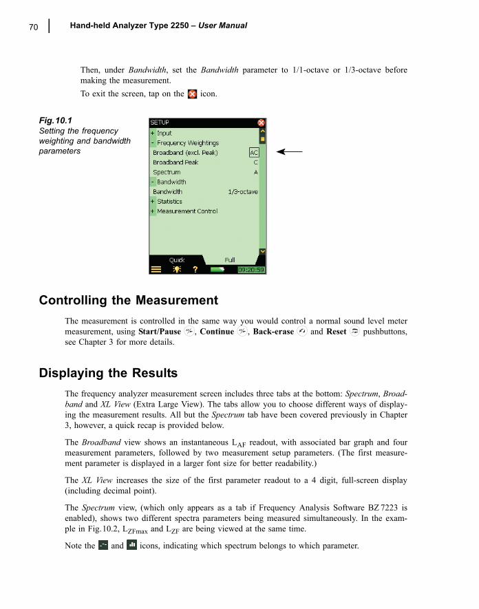
70 Hand-held Analyzer Type 2250 � User Manual
Then, under Bandwidth, set the Bandwidth parameter to 1/1-octave or 1/3-octave beforemaking the measurement.To exit the screen, tap on the icon.
Fig.10.1Setting the frequency weighting and bandwidth parameters
Controlling the MeasurementThe measurement is controlled in the same way you would control a normal sound level metermeasurement, using Start/Pause , Continue , Back-erase and Reset pushbuttons,see Chapter 3 for more details.
Displaying the ResultsThe frequency analyzer measurement screen includes three tabs at the bottom: Spectrum, Broad-band and XL View (Extra Large View). The tabs allow you to choose different ways of display-ing the measurement results. All but the Spectrum tab have been covered previously in Chapter3, however, a quick recap is provided below.
The Broadband view shows an instantaneous LAF readout, with associated bar graph and fourmeasurement parameters, followed by two measurement setup parameters. (The first measure-ment parameter is displayed in a larger font size for better readability.)
The XL View increases the size of the first parameter readout to a 4 digit, full-screen display(including decimal point).
The Spectrum view, (which only appears as a tab if Frequency Analysis Software BZ 7223 isenabled), shows two different spectra parameters being measured simultaneously. In the exam-ple in Fig.10.2, LZFmax and LZF are being viewed at the same time.
Note the and icons, indicating which spectrum belongs to which parameter.
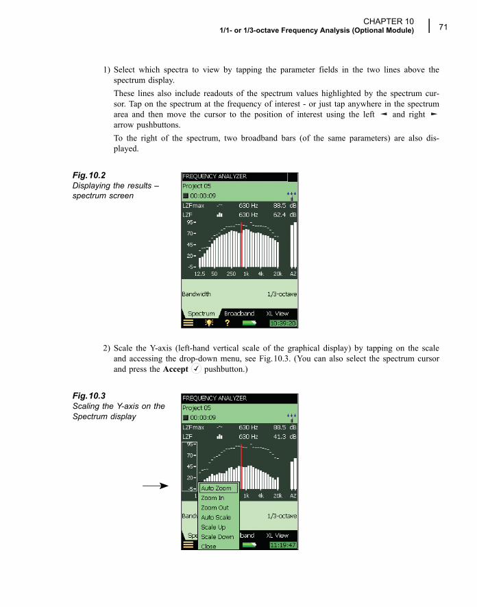
CHAPTER 101/1- or 1/3-octave Frequency Analysis (Optional Module) 71
1) Select which spectra to view by tapping the parameter fields in the two lines above thespectrum display. These lines also include readouts of the spectrum values highlighted by the spectrum cur-sor. Tap on the spectrum at the frequency of interest - or just tap anywhere in the spectrumarea and then move the cursor to the position of interest using the left and right arrow pushbuttons. To the right of the spectrum, two broadband bars (of the same parameters) are also dis-played.
Fig.10.2Displaying the results �spectrum screen
2) Scale the Y-axis (left-hand vertical scale of the graphical display) by tapping on the scaleand accessing the drop-down menu, see Fig.10.3. (You can also select the spectrum cursorand press the Accept pushbutton.)
Fig.10.3Scaling the Y-axis on the Spectrum display
72 Hand-held Analyzer Type 2250 � User Manual
Select Auto Zoom to adjust the range of the Y-axis for best fit of the measured spectrum.Select Zoom In/Zoom Out to adjust the zoom.Select Scale Up/Scale Down to adjust the full scale value on the Y-axis � or select AutoScale to select the best scaling for viewing the spectra � without adjusting the zoom.Auto Zoom and Auto Scale automatically close the drop-down menu, otherwise, selectClose, tap outside the dropdown list or use the left arrow pushbutton to close the menu.
Hint: a quick way of auto zooming is to tap anywhere in the spectrum and then press theAccept pushbutton twice.
Saving ResultsMeasurements are saved and can be viewed later, in the same way as described for the SoundLevel Meter Project in Chapter 3.
73
Chapter 11Logging (Optional Module)
2250 Logging Software BZ 7224 enables you to measure and save data periodically on SD- orCF-Cards. The module is optimised for attended use, which means that while measuring youcan annotate any sound on-line, as well as �mark� up to five different sound categories on-line.
The main benefit is that data is documented on-site and is therefore ready for post-processingand reporting back at the office using Utility Software for Hand-held Analyzers BZ 5503 orother post-processing software such as Noise Explorer Type 7815, Evaluator Type 7820, Protec-tor Type 7825 or Microsoft® Excel.
In addition to measuring broadband parameters (see Chapter 3) and spectraa (see Chapter 10),the logging module allows you to simultaneously log the following parameters:� Broadband Parameters (including broadband statistics)
� Spectraa
� Broadband Parameters every 100 ms
� Record the measured signalb
Check the About Menu to see whether you have the right license to run the Logging module.(The About Menu is accessed from built-in help � tap on the shortcut bar, then selectAbout.) See Chapter 9 for instructions on installing the license for the Logging Module.
Setting up the Instrument1) Select the LOGGING Project Template. (See �What is a Project Template?� on page 14
for more details on templates.) The Project Template is displayed on the black banner at thetop of the screen. If this banner does not display LOGGING, tap on the banner and selectLOGGING from the drop-down that appears. Note: The Logging Project Template assumes you have a license for the Frequency Analy-sis Software. If not, then select the LOGGING SLM Project template instead.
a. Requires Frequency Analysis Software BZ 7223b. Requires Sound Recording Software BZ 7226
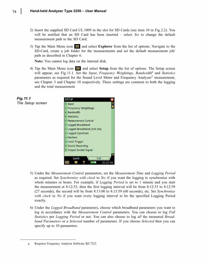
74 Hand-held Analyzer Type 2250 � User Manual
2) Insert the supplied SD Card UL 1009 in the slot for SD Cards (see item 10 in Fig.2.2). Youwill be notified that an SD Card has been inserted � select Yes to change the defaultmeasurement path to the SD Card.
3) Tap the Main Menu icon and select Explorer from the list of options. Navigate to theSD-Card, create a job folder for the measurements and set the default measurement job/path as described in Chapter 6.Note: You cannot log data on the internal disk.
4) Tap the Main Menu icon and select Setup from the list of options. The Setup screenwill appear, see Fig.11.1. Set the Input, Frequency Weightings, Bandwidtha and Statisticsparameters as required for the Sound Level Meter and Frequency Analyzer1 measurement,see Chapter 3 and Chapter 10 respectively. These settings are common to both the loggingand the total measurement.
Fig.11.1The Setup screen
5) Under the Measurement Control parameters, set the Measurement Time and Logging Periodas required. Set Synchronize with clock to Yes if you want the logging to synchronise withwhole minutes or hours. For example, if Logging Period is set to 1 minute and you startthe measurement at 8:12:33, then the first logging interval will be from 8:12:33 to 8:12:59(27 seconds), the second will be from 8:13:00 to 8:13:59 (60 seconds), etc. Set Synchronizewith clock to No if you want every logging interval to be the specified Logging Periodexactly.
6) Under the Logged Broadband parameters, choose which broadband parameters you want tolog in accordance with the Measurement Control parameters. You can choose to log FullStatistics per Logging Period or not. You can also choose to log all the measured Broad-band Parameters or a Selected number of parameters. If you choose Selected then you canspecify up to 10 parameters.
a. Requires Frequency Analysis Software BZ 7223
CHAPTER 11Logging (Optional Module) 75
7) The Logged Broadband (100 ms) parameter allows you to log LAeq (with an elapsed timeof 100 ms and a logging period of 100 ms) and/or LAF (with a logging period of 100 ms)irrespective of the other logging parameters.
8) The Logged Spectruma parameter allows you to choose which spectra to log. You canspecify to log All, None or up to 3 Selected spectra.
9) Under Markers you can specify the names of the five available markers. The markers arepredefined as follows:
� Marker 1: �Exclude� � can be controlled by pressing the Back-erase pushbutton
� Marker 2: �Manual� � can be controlled by pressing the Manual Event pushbutton � Marker 3: �Level� � can be controlled by the Level Trigger detection� Marker 4: �Marker 4�� Marker 5: �Marker 5�� Marker 6: �Sound� � is set when recording sound (requires Sound Recording Software
BZ 7226)All markers can be controlled by the stylus in the Profile display.You can set a Pre-marker Time between 0 and 5 seconds. This will start markers 1, 2 or 3the set number of pre-marker seconds before the point where the Back-erase pushbutton,the Manual Event pushbutton, or the Level Trigger, respectively, are pressed. See �Mark-ing Sound Categories� on page 80.
10) Under the Level Trigger parameters, choose the settings for triggering the number 3 marker�Level� and for starting a sound recording � see Chapter 12. � Set Level Trigger Control to On to enable the level trigger facility, or Off to disable the
facility� Set Trigger Parameter to the parameter you want to monitor, e.g., LAeq � see Appendix A
for the total list of parameters� Set Start Slope to Rising if you want to start when the Trigger Parameter exceeds Start
Level (and stop when it goes below Stop Level) or to Falling if you want to start when the Trigger Parameter goes below Start Level (and stop when it exceeds Stop Level)
� Set Start Duration for the number of seconds the Trigger Parameter must fulfill the trig-ger condition before the trigger point is acknowledged
� Set Stop Duration for the number of seconds the Trigger Parameter doesn�t fulfill the trigger condition anymore to acknowledge the end point of the trigger. (See the relation-ship between the trigger parameters in Fig.11.2)
a. Requires Frequency Analysis Software BZ 7223
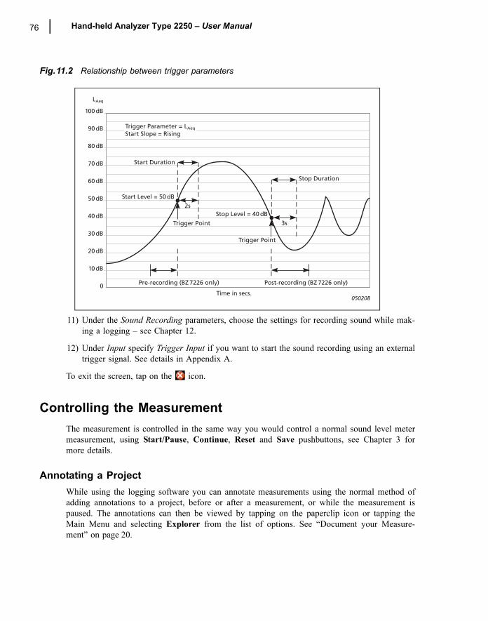
76 Hand-held Analyzer Type 2250 � User Manual
Fig.11.2 Relationship between trigger parameters
11) Under the Sound Recording parameters, choose the settings for recording sound while mak-ing a logging � see Chapter 12.
12) Under Input specify Trigger Input if you want to start the sound recording using an externaltrigger signal. See details in Appendix A.
To exit the screen, tap on the icon.
Controlling the MeasurementThe measurement is controlled in the same way you would control a normal sound level metermeasurement, using Start/Pause, Continue, Reset and Save pushbuttons, see Chapter 3 formore details.
Annotating a ProjectWhile using the logging software you can annotate measurements using the normal method ofadding annotations to a project, before or after a measurement, or while the measurement ispaused. The annotations can then be viewed by tapping on the paperclip icon or tapping theMain Menu and selecting Explorer from the list of options. See �Document your Measure-ment� on page 20.
Start Level = 50 dB
Start Duration
100 dB
90 dB
80 dB
70 dB
60 dB
50 dB
40 dB
30 dB
20 dB
10 dB
0Time in secs.
Trigger Point
Trigger Point
Pre-recording (BZ 7226 only) Post-recording (BZ 7226 only)
2sStop Level = 40 dB
Stop Duration
3s
Trigger Parameter = LAeq
Start Slope = Rising
LAeq
050208
CHAPTER 11Logging (Optional Module) 77
However, if you choose to annotate the profile during the measurement, the annotation icon willappear below the profile, not as a paperclip icon in the status field or attached to a project inExplorer, as described previously. In this case, you view the annotation using the methoddescribed under �The Profile� on page 79.
Recording SoundYou can record sound during the measurementa by pressing the Manual Event pushbutton(Manual Event marker), the Back-erase pushbutton (Exclude Marker) or when the level of aspecific parameter exceeds a certain level � or you can record sound through the whole meas-urement � depending on the Sound Recording setting in the Setup � see details in Chapter 12.
Displaying the ResultsThe Logging measurement screen (or Profile View) includes three tabs at the bottom: Profile,Spectrum and Broadband View (the Logging SLM includes the tabs: Profile, Broadband and XLView). The tabs allow you to choose different ways of displaying the measurement results. Allbut the Profile tab have been covered previously in Chapters 3 and 10, however a quick recap isprovided below.
The Broadband view shows an instantaneous LAF readout, with associated bar graph and anumber of measurement parameters. (The first measurement parameter is displayed in a largerfont size for better readability.)
The XL View increases the size of the first parameter readout to a 4 digit, full-screen display(including decimal point).
The Spectrum view shows two different spectra parameters being measured simultaneously.
The Profile ViewThe Profile view displays a profile of a logged broadband parameter (dB versus time). This isvery convenient when marking sound categories on-line or annotating the measurement. SeeFig.11.3.
a. Requires License for Sound Recording Software BZ 7226
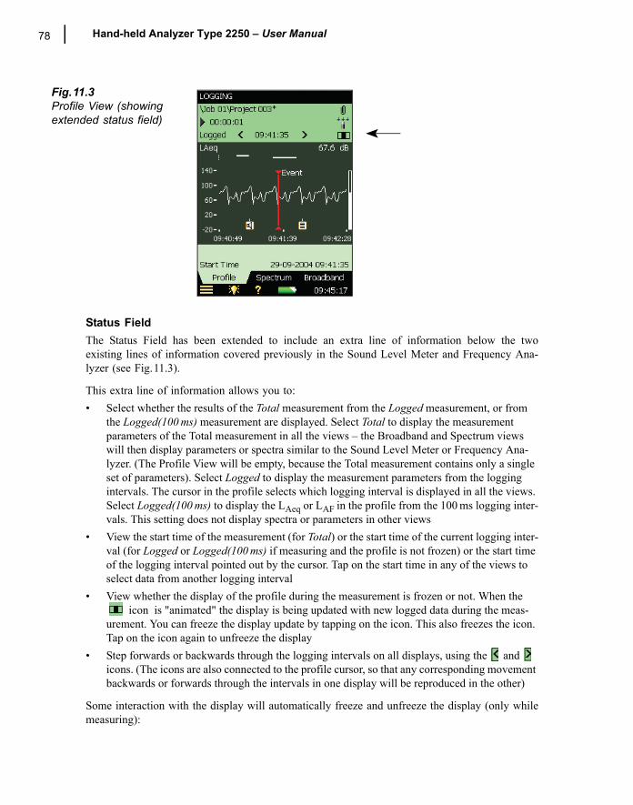
78 Hand-held Analyzer Type 2250 � User Manual
Fig.11.3Profile View (showing extended status field)
Status FieldThe Status Field has been extended to include an extra line of information below the twoexisting lines of information covered previously in the Sound Level Meter and Frequency Ana-lyzer (see Fig.11.3).
This extra line of information allows you to:� Select whether the results of the Total measurement from the Logged measurement, or from
the Logged(100 ms) measurement are displayed. Select Total to display the measurement parameters of the Total measurement in all the views � the Broadband and Spectrum views will then display parameters or spectra similar to the Sound Level Meter or Frequency Ana-lyzer. (The Profile View will be empty, because the Total measurement contains only a single set of parameters). Select Logged to display the measurement parameters from the logging intervals. The cursor in the profile selects which logging interval is displayed in all the views. Select Logged(100 ms) to display the LAeq or LAF in the profile from the 100 ms logging inter-vals. This setting does not display spectra or parameters in other views
� View the start time of the measurement (for Total) or the start time of the current logging inter-val (for Logged or Logged(100 ms) if measuring and the profile is not frozen) or the start time of the logging interval pointed out by the cursor. Tap on the start time in any of the views to select data from another logging interval
� View whether the display of the profile during the measurement is frozen or not. When the icon is "animated" the display is being updated with new logged data during the meas-
urement. You can freeze the display update by tapping on the icon. This also freezes the icon. Tap on the icon again to unfreeze the display
� Step forwards or backwards through the logging intervals on all displays, using the and icons. (The icons are also connected to the profile cursor, so that any corresponding movement backwards or forwards through the intervals in one display will be reproduced in the other)
Some interaction with the display will automatically freeze and unfreeze the display (only whilemeasuring):
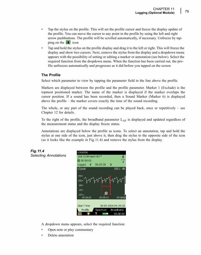
CHAPTER 11Logging (Optional Module) 79
� Tap the stylus on the profile. This will set the profile cursor and freeze the display update of the profile. You can move the cursor to any point in the profile by using the left and right arrow pushbuttons. The profile will be scrolled automatically, if necessary. Unfreeze by tap-ping on the icon
� Tap and hold the stylus on the profile display and drag it to the left or right. This will freeze the display and show two cursors. Next, remove the stylus from the display and a dropdown menu appears with the possibility of setting or editing a marker or annotation (see below). Select the required function from the dropdown menu. When the function has been carried out, the pro-file unfreezes automatically and progresses as it did before you tapped on the screen
The ProfileSelect which parameter to view by tapping the parameter field in the line above the profile.
Markers are displayed between the profile and the profile parameter. Marker 1 (Exclude) is thetopmost positioned marker. The name of the marker is displayed if the marker overlaps thecursor position. If a sound has been recorded, then a Sound Marker (Marker 6) is displayedabove the profile � the marker covers exactly the time of the sound recording.
The whole, or any part of the sound recording can be played back, once or repetitively � seeChapter 12 for details.
To the right of the profile, the broadband parameter LAF is displayed and updated regardless ofthe measurement status and the display freeze status.
Annotations are displayed below the profile as icons. To select an annotation, tap and hold thestylus at one side of the icon, just above it, then drag the stylus to the opposite side of the icon(so it looks like the example in Fig.11.4) and remove the stylus from the display.
Fig.11.4Selecting Annotations
A dropdown menu appears, select the required function:� Open note or play commentary� Delete annotation
80 Hand-held Analyzer Type 2250 � User Manual
� Move annotation (to the position on the display where the stylus was removed from the dis-play)
Scale the Y-axis (left-hand vertical scale of the graphical display) by tapping on the scale andaccessing the drop-down menu (as in the Spectrum display):� Select Auto Zoom to adjust the range of the Y-axis for best fit of the measured spectrum� Select Zoom In/Zoom Out to adjust the zoom� Select Scale Up/Scale Down to adjust the full scale value on the Y-axis - or select Auto Scale
to select the best scaling for viewing the spectra - without adjusting the zoom� Auto Zoom and Auto Scale automatically close the drop-down menu, otherwise, select Close,
tap outside the dropdown list or use the left arrow pushbutton to close the menu
Marking Sound CategoriesUse this facility to categorise the sound while you are measuring, or while you are observingthe different kinds of sound on the display. This will make it much easier to do the post-processing and reporting back in the office.
You can mark up to five sound categories on-line. The markers are displayed as horizontal linesabove the sound profile, see Fig.11.3. There are two main types of marker:� An Exclude Marker � this allows you to mark a sound you want to exclude from your meas-
urement later during post-processing or reporting. (It does not remove any data from your measurement)
� An Event Marker � this allows you to mark a particular sound of interest during your measure-ment
On Type 2250, Marker 1 is used as an Exclude Marker, while Markers 2 to 5 are used as EventMarkers. All four event markers can be user-defined. You can define a marker by tapping onthe Main Menu icon and selecting Setup, followed by Markers.
Marker 2 is set to a Manual Event marker by default � it can be controlled by the ManualEvent pushbutton and the stylus.
Marker 3 is set to a Level Event marker by default � it can be controlled by the level triggerfacility and the stylus.
Marker 6 is used as a Sound Marker and shows the size of the sound recording.
Type 2250 allows you to view the markers at a later date by recalling the data and viewing thedesired profile. (This can also be done if you have transferred the data to Type 7815 NoiseExplorer).
If required, Type 7820 Evaluator and Type 7825 Protector can use the markers in their calcula-tions. Marker number 1 (the Exclude Marker) will always be used as an Exclude Marker, whilemarkers 2 to 5 will be used as defined in Type 7820 Evaluator/Type 7825 Protector software.The marker names, however, will be transferred from Type 2250. Marker 6 will be used assound marker.
CHAPTER 11Logging (Optional Module) 81
Marking During the Measurement:The measurement parameter is displayed as a progressing profile.
Use of pushbuttons:Press the Back-erase pushbutton to start an Exclude Marker (marker number 1). The markeris displayed above the profile. Press the button once more to stop the Exclude Marker.
Press the Manual Event pushbutton to start a Manual Event Marker (marker number 2).The marker is displayed above the profile. Press the button once more to stop the Manual EventMarker.
Use of stylus:Tap and hold the stylus on the profile display at the position where you want the marker tostart. This will freeze the display and show a cursor at the position of the stylus. Then drag thestylus left or right to the position where you want the marker to end. This will display a secondcursor. Next, remove the stylus from the display and a dropdown menu appears showing thefive markers you have specified in the setup. Select the marker you require. The marker isdisplayed above the profile, the cursors disappear and the profile unfreezes and progresses as itdid before you tapped on the screen.
Note: If you select Sound Marker, then the sound for this part will be recorded � see Chapter12 for details.
Marking Measurement While it is Paused:The measurement parameter is displayed as a profile while the measurement is paused.
You can use the stylus to mark the sound categories:Tap and hold the stylus in the profile display at the position where you want the marker to start.This will display a cursor at the position of the stylus. Then drag the stylus left or right to theposition where you want the marker to end. This will display a second cursor. Next, remove thestylus from the display and a dropdown menu appears showing the five markers you havespecified in the setup. Select the marker you require. The marker is displayed above the profileand the cursors disappear.
Editing Markers on ProfilesTo widen a marker:
1) Tap and hold the stylus on the profile display at a position within the marker range.
2) Drag the stylus left or right to the position where you want the marker to end.
3) Remove the stylus from the display and a dropdown menu appears.
4) Select the marker you want to widen from the dropdown menu.
To narrow a marker:
1) Tap and hold the stylus on the profile display at the position inside the marker range whereyou want it to stop.
82 Hand-held Analyzer Type 2250 � User Manual
2) Drag the stylus left or right to a position outside the marker range.
3) Remove the stylus from the display and a dropdown menu appears.
4) Select Delete for the marker you want to narrow from the dropdown menu. The part wherethe marker overlaps the gap between the two cursors will be deleted.
To delete a marker:
1) Tap and hold the stylus in the profile display at a position to the left of the marker youwant to delete.
2) Drag the stylus to a position to the right of the marker.
3) Remove the stylus from the display and a dropdown menu appears.
4) Select Delete for the marker you want to delete from the dropdown menu.Note: Sound markers cannot be edited. Marking the whole sound marker (or part of it) andselecting Delete will delete the whole sound marker and sound recording.
Annotate Sound CategoriesYou can annotate the measurement on-line with a spoken comment or a written note. Theannotation is displayed as an icon below the sound profile.
Annotating During the Measurement:The measurement parameter is displayed as a progressing profile.
Use of pushbuttons:Press and hold down the Commentary pushbutton and talk to the instrument to make yourcomment. Release the button when finished. This will insert a comment annotation in the pro-file at the time when the button was pressed.
Use of stylus:Tap and hold the stylus in the profile display at the position where you want the annotation tostart. This will freeze the display and display a cursor at the position of the stylus. Then dragthe stylus a little to the left or right and raise it again. A dropdown menu appears and below thefive markers you can select Add Comment or Add Note to add a spoken comment or write anote. When finished, the Comment or Note is inserted in the profile, the cursors disappear andthe profile unfreezes and progresses as before tapping on the screen.
Annotating While the Measurement is Paused:The measurement parameter is displayed as a profile while the measurement is paused.
Use of stylus to annotate the sound:Tap and hold the stylus in the profile display at the position where you want the marker to start.This will display a cursor at the position of the stylus. Next, drag the stylus a little to the left orright and remove the stylus from the display. A dropdown menu appears and below the fivemarkers you can select Add Comment or Add Note to add a spoken comment or write a note.When finished the Comment or Note is inserted in the profile and the cursors disappear.
CHAPTER 11Logging (Optional Module) 83
Use of pushbuttons:Using the Commentary pushbutton during a pause means that the comment annotation willbe added to the project instead of the profile. (The annotations can be viewed by tapping on thepaperclip icon or tapping the Main Menu and selecting Explorer from the list of options. See�Document your Measurement� on page 20.)
Editing Annotations on ProfilesTo move an annotation:
1) Tap and hold the stylus on the profile display at a position on one side of the annotationicon.
2) Drag the stylus through the annotation icon to the position where you want the annotationmoved to.
3) Remove the stylus from the display and a dropdown menu appears.
4) Select Move Comment (or Move Note) from the dropdown menu.
To delete an annotation:
1) Tap and hold the stylus on the profile display at a position to the left of the annotation iconyou want to delete.
2) Drag the stylus to a position to the right of the annotation.
3) Remove the stylus from the display and a dropdown menu appears.
4) Select Delete for the annotation you want to delete from the dropdown menu.
Saving and Recalling ResultsMeasurements are saved and can be viewed later, in the same way as described for the SoundLevel Meter Project in Chapters 3 and 6.
Note: The viewer only displays the Total results. To display the logged data and see or hearannotations � or even edit the markers or insert new markers and annotations � you must Openthe saved project instead of Viewing it.

84 Hand-held Analyzer Type 2250 � User Manual
85
Chapter 12Sound Recording (Optional Module)
2250 Sound Recording Software BZ 7226 allows you to record sound during measurementusing one of the software modules BZ 7222, BZ 7223 or BZ 7224. The sound recording can becontrolled manually or by using an external trigger signal. The recording can also be triggeredwhen a measured parameter exceeds a preset level (BZ 7224 only). The recorded sound can beplayed back and listened to using the supplied earphones, HT 0015. Sound is recorded directlyto CF or SD memory cards.
The main benefit is that data is documented on-site and is therefore ready for post-processingand reporting back at the office using Utility Software for Hand-held Analyzers BZ 5503 orother post-processing software such as Noise Explorer Type 7815, Evaluator Type 7820, Protec-tor Type 7825 or Microsoft® Excel.
Check the About Menu to see whether you have the right license to run the Sound Recordingmodule. (The About Menu is accessed from built-in help � tap on the shortcut bar, thenselect About.) See Chapter 9 for instructions on installing the license for the Sound RecordingModule.
Sound Level Meter and Frequency Analysis SoftwareYou can use the Sound Recording facility together with the Sound Level Meter Software andthe Frequency Analysis Software. You can record the sound for the whole measurement periodor you can record sound for controlled parts of the measurement. The recordings are attached tothe project as annotations, named �Soundrec N�, where N is the number of the recording for theproject. (See �Document your Measurement� on page 20 and �Viewing or Listening to Annota-tions� on page 46 for a description of how to use annotations.)
Note 1: Sound recordings can only be done during measurements.
Note 2: Sound recordings can only be done on projects saved on SD or CF cards.
Setting up the Instrument 1) Select a Sound Level Meter Project Template or a Frequency Analyzer Project Template.
(See �What is a Project Template?� on page 14 for more details on templates.)
86 Hand-held Analyzer Type 2250 � User Manual
2) Insert the supplied SD Card UL 1009 in the slot for SD Cards (see item 10 in Fig.2.2).
3) Tap the Main Menu icon and select Explorer from the list of options. Navigate to theSD Card, create a job folder for the measurements and set the default measurement job/path as described in Chapter 6.
Note: You cannot record sound on the internal disk.
4) Tap the Main Menu icon and select Setup from the list of options. Set all the parame-ters as required for the Sound Level Meter or Frequency Analyzer measurement, see Chap-ter 3 and Chapter 10 respectively.
5) Under Sound Recording you can specify the Recording Control parameters as follows:� Automatic, if you want to start the recording when you start the measurement and stop
when you pause the measurement, and to limit the recording to Maximum Duration, if Duration Limit is set to On
� Manual Event, if you want to start and stop the recording using the Manual Event push-button during the measurement and to limit the duration of the recording, if Duration Limit is set to On. In this case the recording will be at least Minimum Duration long, but no longer than the Maximum Duration. Use Pre-recording Time and Post-recording Time to specify how much extra you want to be recorded before and after the event.
� External Event, if you want to start and stop the recording using an external trigger signal, connected to the Trigger Input. See details in Appendix A.
� Off, if you don�t want to record sound
6) Set Recording Quality to High, Medium, Fair or Low in accordance with your needs. Note,however, that high quality requires more disk space than low quality � see details in Ap-pendix A.
7) Set Recorded Signal to either Input A-weighted, Input C-weighted or Input Z-weighted. Input C-weighted is suitable for recordings used afterwards to identify the sound source � itcontains all the audible content of the signal, but reduces the low-frequency noise fromwind, etc.
8) Set Automatic Gain Control to On � if you don�t know the dynamic of the signal before-hand, or the dynamic is very high, then the 120 dB dynamic range (from max. input leveland down) will be converted to 40 dB. Otherwise, set it to Off and specify the Peak Record-ing Level.
9) Under Input you specify Trigger Input if you want to start the sound recording using anexternal trigger signal. See details in Appendix A.
To exit the screen, tap on the icon.
Controlling the RecordingThe measurement is controlled in the same way you would control a normal sound level metermeasurement, using Start/Pause, Continue, Reset and Save pushbuttons, see Chapter 3 formore details.
CHAPTER 12Sound Recording (Optional Module) 87
When the measurement signal is being recorded, the recording icon is displayed in thestatus field. The recording is attached to the project as an annotation. The paperclip icon isthen displayed to indicate that the project has been annotated.
When Recording Control is set to Automatic, the recording will start when the measurement isstarted and last for the Maximum Duration or the Elapsed Time, whichever is smallest. If youcontinue a paused measurement, then a new recording is started.
When Recording Control is set to Manual Event, the recording will start the first time you pressthe Manual Event pushbutton during the measurement, and stop the second time you press it;if you press it a second time before the Minimum Duration has elapsed, then the recording willcontinue until Minimum Duration has elapsed; if you press it a second time after MaximumDuration has elapsed, then the recording has already been stopped when Maximum Durationelapsed and the pushbutton will initiate a new recording instead.
When Recording Control is set to External Event, and Trigger Input is set to Voltage Level, thenrecording is started when the voltage level is �high� and stopped when voltage level is �low�(see details in Appendix A). Duration Limit has no effect on this setting.
If Pre-recording Time has been set, then the recording will start this time before you hit theManual Event pushbutton. This is possible because the recording is done continuously in aninternal buffer, ready to be saved as a wave file. The Pre-recording Time is limited by thisbuffer size and the Recording Quality � see details in appendix A.
Note: Very long sound recordings will be split into wave files containing maximum 10 minutes,i.e., a 35 minute sound recording will consist of 4 wave files, three with 10 minutes sound andone with 5 minutes sound.
Playing the Recording Sound recordings are attached to the measurement project as annotations. The paperclip icon is displayed in the status field to indicate this. Tap on the paperclip to open the list of annota-tions. Tap on the annotation to play it back � see details in Chapter 3 and Chapter 6.
Logging SoftwareYou can use the Sound Recording facility together with the Logging Software. You can recordthe sound for the whole measurement period or you can record sound for controlled parts of themeasurement. The recordings are attached to the profile as sound markers. The sound record-ings can be controlled by the Manual Event pushbutton, the Back-erase pushbutton, an exter-nal trigger signal, or by the level of the measured signal. You can also control the soundrecording using the stylus to mark the interesting part on the profile.
Note 1: Sound recordings can only be done during measurements.
Note 2: Sound recordings can only be done on projects saved on SD or CF cards.
88 Hand-held Analyzer Type 2250 � User Manual
Setting up the Instrument 1) Select a Logging or Logging SLM Project Template. (See �What is a Project Template?�
on page 14 for more details on templates.)
2) Insert the supplied SD Card UL 1009 in the slot for SD Cards (see item 10 in Fig.2.2).
3) Tap the Main Menu icon and select Explorer from the list of options. Navigate to theSD Card, create a job folder for the measurements and set the default measurement job/path as described in Chapter 6.
Note: You cannot record sound on the internal disk.
4) Tap the Main Menu icon and select Setup from the list of options. Set all the parame-ters as required for the Logging measurement, see Chapter 11.
5) Under Sound Recording you can specify the Recording Control parameters as follows:� Automatic, if you want to start the recording when you start the measurement and stop
when you pause the measurement, and to limit the recording to Maximum Duration, if Duration Limit is set to On
� Manual Event, if you want to start and stop the recording using the Manual Event push-button during the measurement
� Exclude Event, if you want to start and stop the recording using the Back-erase pushbut-ton during the measurement
� External Event, if you want to start and stop the recording using an external trigger signal, connected to the Trigger Input
� Level Event, if you want to start and stop the recording based on the level trigger settings during the measurement
� All Events, if you want to start and stop the recording based on any of the eventsNote: When Recording Control set to any of the events, you can limit the duration ofthe recording, if Duration Limit is set to On. In this case the recording will be at leastMinimum Duration long, but no longer than the Maximum Duration. Use Pre-recordingTime and Post-recording Time to specify how much extra you want to be recordedbefore and after the event
� Off, if you don�t want to record sound
6) Set Recording Quality to High, Medium, Fair or Low in accordance with your needs, note,however, that the high quality requires more disk space than low quality � see details inAppendix A.
7) Set Recorded Signal to either Input A-weighted, Input C-weighted or Input Z-weighted. Input C-weighted is suitable for recordings used afterwards to identify the sound source � itcontains all the audible content of the signal, but reduces the low-frequency noise fromwind, etc.
8) Set Automatic Gain Control to On � if you don�t know the dynamic of the signal before-hand, or the dynamic is very high, then the 120 dB dynamic range (from max. input leveland down) will be converted to 40 dB. Otherwise, set it to Off and specify the Peak Record-ing Level.
CHAPTER 12Sound Recording (Optional Module) 89
Under Input you specify Trigger Input if you want to start the recording using an externaltrigger signal. See details in Appendix A.
To exit the screen, tap on the icon.
Controlling the Recording The measurement is controlled in the same way you would control a normal logging measure-ment, using Start/Pause, Continue, Reset and Save pushbuttons, see Chapter 11 for moredetails.
When the measurement signal is being recorded, then the recording icon is displayed in thestatus field. The recording is attached to the profile as a Marker 6 (Sound).
If you set Recording Control to Automatic, the recording will start when the measurement isstarted and last for Maximum Duration or Elapsed Time, whichever is smallest. If you continuea paused measurement, then a new recording is started.
If you set Recording Control to Manual Event, the recording will start the first time you pressthe Manual Event pushbutton during the measurement (this starts a Manual Event marker anda Sound marker), and stop the second time you press it; if you press it a second time beforeMinimum Duration has elapsed, then the recording will continue until Minimum Duration haselapsed; if you press it a second time after Maximum Duration has elapsed, then the recordinghas already stopped when Maximum Duration elapsed, and the pressing the button will have noeffect on the sound recording (the Manual Event marker, however, is stopped).
If you set Recording Control to Exclude Event, the recording will start the first time you pressthe Back-Erase pushbutton during the measurement (this starts an Exclude Event marker and aSound marker), and stop the second time you press it � the behaviour will be similar to controlby the Manual Event pushbutton.
When Recording Control is set to External Event, and Trigger Input is set to Voltage Level, thenrecording is started when the voltage level is �high� and stopped when voltage level is �low�(see details in Appendix A). Duration Limit has no effect on this setting.
If you set Recording Control to Level Event, the recording will start, controlled by the leveltrigger � see Chapter 11 for details.
If you set Recording Control to All Events, the recording will start when any of the eventsabove become active, and stop when all events are inactive again.
If Pre-recording Time has been set, then the recording will start this time before the Eventappears. This is possible because the recording is done continuously in an internal buffer, readyto be saved as a wave file. The Pre-recording Time is limited by this buffer size and theRecording Quality � see details in Appendix A.
Note: Very long sound recordings will be split into wave files containing maximum 10 minutes,i.e., a 35 minute sound recording will consist of 4 wave files, three with 10 minutes sound andone with 5 minutes sound.
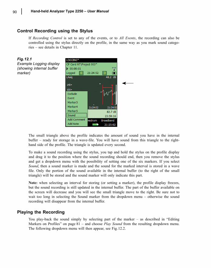
90 Hand-held Analyzer Type 2250 � User Manual
Control Recording using the StylusIf Recording Control is set to any of the events, or to All Events, the recording can also becontrolled using the stylus directly on the profile, in the same way as you mark sound catego-ries � see details in Chapter 11.
Fig.12.1Example Logging display (showing internal buffer marker)
The small triangle above the profile indicates the amount of sound you have in the internalbuffer � ready for storage in a wave-file. You will have sound from this triangle to the right-hand side of the profile. The triangle is updated every second.
To make a sound recording using the stylus, you tap and hold the stylus on the profile displayand drag it to the position where the sound recording should end, then you remove the stylusand get a dropdown menu with the possibility of setting one of the six markers. If you selectSound, then a sound marker is made and the sound for the marked interval is stored in a wavefile. Only the portion of the sound available in the internal buffer (to the right of the smalltriangle) will be stored and the sound marker will only indicate this part.
Note: when selecting an interval for storing (or setting a marker), the profile display freezes,but the sound recording is still updated in the internal buffer. The part of the buffer available onthe screen will decrease and you will see the small triangle move to the right. Be sure not towait too long in selecting the Sound marker from the dropdown menu � otherwise the soundrecording will disappear from the internal buffer.
Playing the Recording You play-back the sound simply by selecting part of the marker � as described in �EditingMarkers on Profiles� on page 81 � and choose Play Sound from the resulting dropdown menu.The following dropdown menu will then appear, see Fig.12.2.
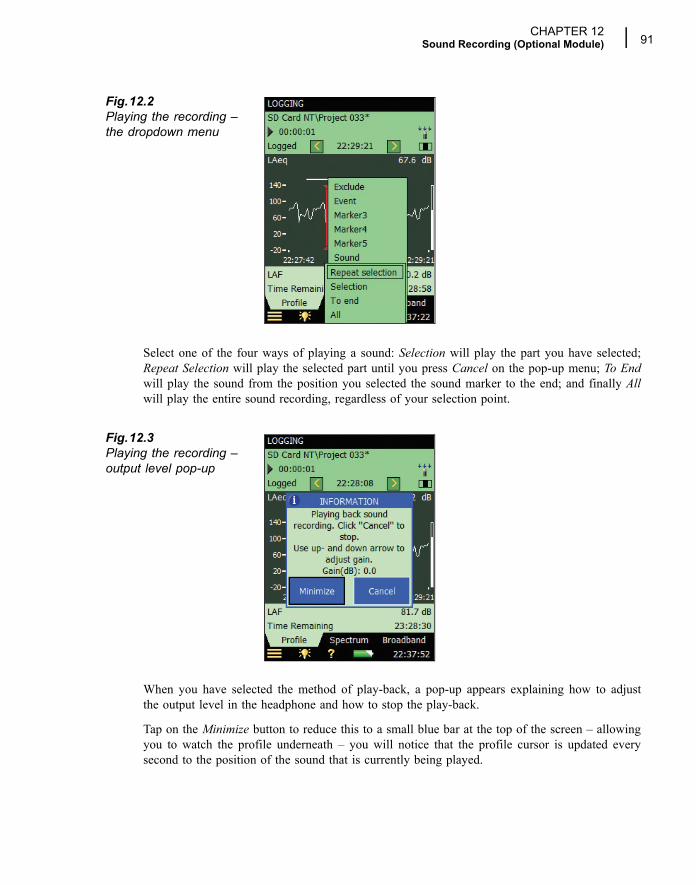
CHAPTER 12Sound Recording (Optional Module) 91
Fig.12.2Playing the recording � the dropdown menu
Select one of the four ways of playing a sound: Selection will play the part you have selected;Repeat Selection will play the selected part until you press Cancel on the pop-up menu; To Endwill play the sound from the position you selected the sound marker to the end; and finally Allwill play the entire sound recording, regardless of your selection point.
Fig.12.3Playing the recording � output level pop-up
When you have selected the method of play-back, a pop-up appears explaining how to adjustthe output level in the headphone and how to stop the play-back.
Tap on the Minimize button to reduce this to a small blue bar at the top of the screen � allowingyou to watch the profile underneath � you will notice that the profile cursor is updated everysecond to the position of the sound that is currently being played.
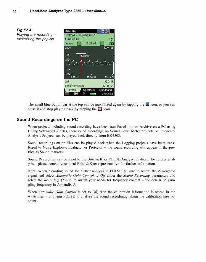
92 Hand-held Analyzer Type 2250 � User Manual
Fig.12.4Playing the recording � minimizing the pop-up
The small blue button bar at the top can be maximized again by tapping the icon, or you canclose it and stop playing back by tapping the icon.
Sound Recordings on the PCWhen projects including sound recording have been transferred into an Archive on a PC usingUtility Software BZ 5503, then sound recordings on Sound Level Meter projects or FrequencyAnalysis Projects can be played back directly from BZ 5503.
Sound recordings on profiles can be played back when the Logging projects have been trans-ferred to Noise Explorer, Evaluator or Protector � the sound recording will appear in the pro-files as Sound markers.
Sound Recordings can be input to the Brüel & Kjær PULSE Analyzer Platform for further anal-ysis � please contact your local Brüel & Kjær representative for further information.
Note: When recording sound for further analysis in PULSE, be sure to record the Z-weightedsignal and select Automatic Gain Control to Off under the Sound Recording parameters andselect the Recording Quality to match your needs for frequency content � see details on sam-pling frequency in Appendix A.
When Automatic Gain Control is set to Off, then the calibration information is stored in thewave files � allowing PULSE to analyse the sound recordings, taking the calibration into ac-count.
93
Chapter 13Specifications
This chapter comprises the specifications that are needed for evaluation of instrument perform-ance characteristics and proper use of the instrument. Some of the applicable sound level meterstandards require additional technical documentation, in particular for pattern evaluation (typeapproval) purposes, but have no bearing on normal use. The additional technical documentationis given in a separate Brüel & Kjær instruction manual (BE 1712).
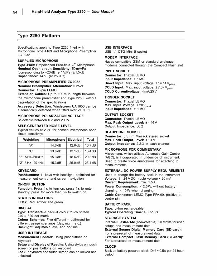
Hand-held Analyzer Type 2250 � User Manual94
Type 2250 Platform
Specifications apply to Type 2250 fitted with Microphone Type 4189 and Microphone Preamplifier ZC 0032
SUPPLIED MICROPHONEType 4189: Prepolarized Free-field ½″ MicrophoneNominal Open-circuit Sensitivity: 50 mV/Pa (corresponding to −26 dB re 1 V/Pa) ± 1.5 dBCapacitance: 14 pF (at 250 Hz)
MICROPHONE PREAMPLIFIER ZC 0032Nominal Preamplifier Attenuation: 0.25 dBConnector: 10-pin LEMOExtension Cables: Up to 100 m in length between the microphone preamplifier and Type 2250, without degradation of the specificationsAccessory Detection: Windscreen UA 1650 can be automatically detected when fitted over ZC 0032
MICROPHONE POLARIZATION VOLTAGESelectable between 0 V and 200 V
SELF-GENERATED NOISE LEVELTypical values at 23°C for nominal microphone open circuit sensitivity:
KEYBOARDPushbuttons: 11 keys with backlight, optimised for measurement control and screen navigation
ON-OFF BUTTONFunction: Press 1 s to turn on; press 1 s to enter standby; press for more than 5 s to switch off
STATUS INDICATORSLEDs: Red, amber and green
DISPLAYType: Transflective back-lit colour touch screen240 × 320 dot matrixColour Schemes: Five different � optimised for different usage scenarios (day, night, etc.)Backlight: Adjustable level and on-time
USER INTERFACEMeasurement Control: Using pushbuttons on keyboardSetup and Display of Results: Using stylus on touch screen or pushbuttons on keyboardLock: Keyboard and touch screen can be locked and unlocked
USB INTERFACEUSB 1.1 OTG Mini B socket
MODEM INTERFACEHayes compatible GSM or standard analogue modems connected through the Compact Flash slot
INPUT SOCKETConnector: Triaxial LEMOInput Impedance: ≥ 1 MΩDirect Input: Max. input voltage: ± 14.14 VpeakCCLD Input: Max. input voltage: ± 7.07 VpeakCCLD Current/voltage: 4 mA/25 V
TRIGGER SOCKETConnector: Triaxial LEMOMax. Input Voltage: ± 20 VpeakInput Impedance: > 1 MΩ
OUTPUT SOCKETConnector: Triaxial LEMOMax. Peak Output Level: ± 4.46 VOutput Impedance: 50Ω
HEADPHONE SOCKETConnector: 3.5 mm Minijack stereo socketMax. Peak Output Level: ± 1.4 VOutput Impedance: 2.2Ω in each channel
MICROPHONE FOR COMMENTARYMicrophone, which utilises Automatic Gain Control (AGC), is incorporated in underside of instrument. Used to create voice annotations for attaching to measurements
EXTERNAL DC POWER SUPPLY REQUIREMENTSUsed to charge the battery pack in the instrumentVoltage: 8 � 24 V DC, ripple voltage < 20 mVCurrent Requirement: min. 1.5 APower Consumption: < 2.5 W, without battery charging, < 10 W when chargingCable Connector: LEMO Type FFA.00, positive at centre pin
BATTERY PACKType: Li-Ion rechargeableTypical Operating Time: > 8 hours
STORAGE SYSTEMInternal Flash-RAM (non-volatile): 20 Mbyte for user setups and measurement dataExternal Secure Digital Memory Card (SD-card): For store/recall of measurement dataExternal Compact Flash Memory Card (CF-card): For store/recall of measurement data
CLOCKBack-up battery powered clock. Drift <0.5s per 24 hour period
Weighting Microphone Electrical Total
�A� 14.6 dB 12.6 dB 16.7 dB
�C� 13.6 dB 13.1 dB 16.4 dB
�Z� 5 Hz�20 kHz 15.3 dB 18.6 dB 20.3 dB
�Z� 3 Hz�20 kHz 15.3 dB 25.0 dB 25.4 dB
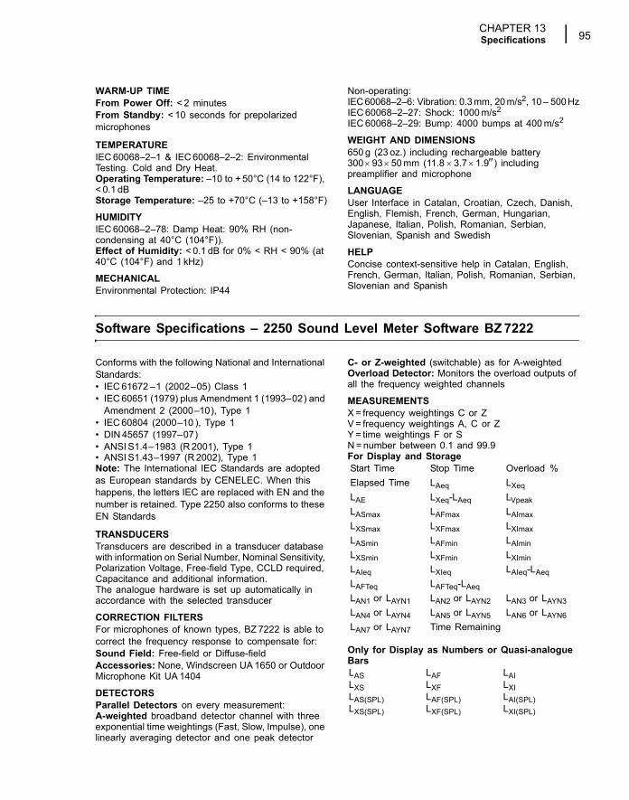
CHAPTER 13Specifications 95
WARM-UP TIMEFrom Power Off: < 2 minutesFrom Standby: < 10 seconds for prepolarized microphones
TEMPERATUREIEC 60068�2�1 & IEC 60068�2�2: Environmental Testing. Cold and Dry Heat.Operating Temperature: �10 to + 50°C (14 to 122°F), < 0.1 dBStorage Temperature: �25 to +70°C (�13 to +158°F)
HUMIDITYIEC 60068�2�78: Damp Heat: 90% RH (non-condensing at 40°C (104°F)).Effect of Humidity: < 0.1 dB for 0% < RH < 90% (at 40°C (104°F) and 1 kHz)
MECHANICALEnvironmental Protection: IP44
Non-operating:IEC 60068�2�6: Vibration: 0.3 mm, 20 m/s2, 10 � 500 HzIEC 60068�2�27: Shock: 1000 m/s2
IEC 60068�2�29: Bump: 4000 bumps at 400 m/s2
WEIGHT AND DIMENSIONS650 g (23 oz.) including rechargeable battery300 × 93 ×50 mm (11.8 × 3.7 ×1.9″) including preamplifier and microphone
LANGUAGEUser Interface in Catalan, Croatian, Czech, Danish, English, Flemish, French, German, Hungarian, Japanese, Italian, Polish, Romanian, Serbian, Slovenian, Spanish and Swedish
HELPConcise context-sensitive help in Catalan, English, French, German, Italian, Polish, Romanian, Serbian, Slovenian and Spanish
Software Specifications � 2250 Sound Level Meter Software BZ 7222
Conforms with the following National and International Standards:� IEC 61672 �1 (2002�05) Class 1� IEC 60651 (1979) plus Amendment 1 (1993�02) and
Amendment 2 (2000�10), Type 1� IEC 60804 (2000�10 ), Type 1� DIN 45657 (1997�07)� ANSI S1.4�1983 (R 2001), Type 1� ANSI S1.43�1997 (R 2002), Type 1Note: The International IEC Standards are adopted as European standards by CENELEC. When this happens, the letters IEC are replaced with EN and the number is retained. Type 2250 also conforms to these EN Standards
TRANSDUCERSTransducers are described in a transducer database with information on Serial Number, Nominal Sensitivity, Polarization Voltage, Free-field Type, CCLD required, Capacitance and additional information. The analogue hardware is set up automatically in accordance with the selected transducer
CORRECTION FILTERSFor microphones of known types, BZ 7222 is able to correct the frequency response to compensate for:Sound Field: Free-field or Diffuse-fieldAccessories: None, Windscreen UA 1650 or Outdoor Microphone Kit UA 1404
DETECTORSParallel Detectors on every measurement:A-weighted broadband detector channel with three exponential time weightings (Fast, Slow, Impulse), one linearly averaging detector and one peak detector
C- or Z-weighted (switchable) as for A-weightedOverload Detector: Monitors the overload outputs of all the frequency weighted channels
MEASUREMENTSX = frequency weightings C or ZV = frequency weightings A, C or ZY = time weightings F or SN = number between 0.1 and 99.9For Display and Storage
Only for Display as Numbers or Quasi-analogue Bars
Start Time Stop Time Overload %Elapsed Time LAeq LXeqLAE LXeq-LAeq LVpeakLASmax LAFmax LAImaxLXSmax LXFmax LXImaxLASmin LAFmin LAIminLXSmin LXFmin LXIminLAIeq LXIeq LAIeq-LAeqLAFTeq LAFTeq-LAeqLAN1 or LAYN1 LAN2 or LAYN2 LAN3 or LAYN3LAN4 or LAYN4 LAN5 or LAYN5 LAN6 or LAYN6LAN7 or LAYN7 Time Remaining
LAS LAF LAILXS LXF LXILAS(SPL) LAF(SPL) LAI(SPL)LXS(SPL) LXF(SPL) LXI(SPL)
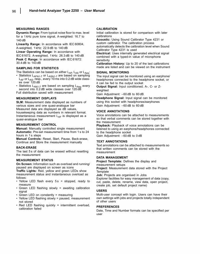
Hand-held Analyzer Type 2250 � User Manual96
MEASURING RANGESDynamic Range: From typical noise floor to max. level for a 1 kHz pure tone signal, A-weighted: 16.7 to 140 dBLinearity Range: In accordance with IEC 60804,A-weighted, 1 kHz: 22.9 dB to 140 dBLinear Operating Range: In accordance with IEC 61672, A-weighted, 1 kHz: 26.3 dB to 140 dBPeak C Range: In accordance with IEC 61672: 30.4 dB to 143 dB
SAMPLING FOR STATISTICSThe Statistics can be based on either LAF, LAS or LAeq:� Statistics LAFN1-7 or LASN1-7 are based on sampling
LAF or LAS, resp., every 10 ms into 0.2 dB wide class-es over 120 dB
� Statistics LAN1-7 are based on sampling LAeq everysecond into 0.2 dB wide classes over 120 dB
Full distribution saved with measurement
MEASUREMENT DISPLAYSSLM: Measurement data displayed as numbers of various sizes and one quasi-analogue barMeasured data are displayed as dB values, housekeeping data as numbers in relevant format.Instantaneous measurement LAF is displayed as a quasi-analogue bar
MEASUREMENT CONTROL Manual: Manually controlled single measurementAutomatic: Pre-set measurement time from 1 s to 24 hours in 1 s stepsManual Controls: Reset, Start, Pause, Back-erase, Continue and Store the measurement manually
BACK-ERASEThe last 5 s of data can be erased without resetting the measurement
MEASUREMENT STATUSOn Screen: Information such as overload and running/paused are displayed on screen as iconsTraffic Lights: Red, yellow and green LEDs show measurement status and instantaneous overload as follows:� Yellow LED flash every 5 s = stopped, ready to
measure� Green LED flashing slowly = awaiting calibration
signal� Green LED on constantly = measuring� Yellow LED flashing slowly = paused, measurement
not stored� Red LED flashing quickly = intermittent overload,
calibration failed
CALIBRATIONInitial calibration is stored for comparison with later calibrationsAcoustic: Using Sound Calibrator Type 4231 or custom calibrator. The calibration process automatically detects the calibration level when Sound Calibrator Type 4231 is usedElectrical: Uses internally generated electrical signal combined with a typed-in value of microphone sensitivityCalibration History: Up to 20 of the last calibrations made are listed and can be viewed on the instrument
SIGNAL MONITORINGThe input signal can be monitored using an earphone/headphones connected to the headphone socket, or it can be fed to the output socketOutput Signal: Input conditioned; A-, C- or Z-weightedGain Adjustment: �60 dB to 60 dBHeadphone Signal: Input signal can be monitored using this socket with headphones/earphonesGain Adjustment: �60 dB to 60 dB
VOICE ANNOTATIONSVoice annotations can be attached to measurements so that verbal comments can be stored together with the measurementPlayback: Playback of voice annotations can be listened to using an earphone/headphones connected to the headphone socketGain Adjustment: �60 dB to 0 dB
TEXT ANNOTATIONSText annotations can be attached to measurements so that written comments can be stored with the measurement
DATA MANAGEMENTProject Template: Defines the display and measurement setupsProject: Measurement data stored with the Project Template Job: Projects are organised in JobsExplorer facilities for easy management of data (copy, cut, paste, delete, rename, view data, open project, create job, set default project name)
USERSMulti-user concept with login. Users can have their own settings with jobs and projects totally independent of other users
PREFERENCESDate, Time and Number formats can be specified per user
CHAPTER 13Specifications 97
Software Specifications � 2250 Frequency Analysis Software BZ 7223
The specifications for BZ 7223 include the specifications for 2250 Sound Level Meter Software BZ 7222. BZ 7223 adds:
STANDARDSConforms with the following National and International Standards:� IEC 61260 (1995�07) plus Amendment 1 (2001�09),
1/1-octave Bands and 1/3-octave Bands, Class 0� ANSI S1.11�1986 (R 1993), 1/1-octave Bands and
1/3-octave Bands, Order 3, Type 0�C� ANSI S1.11� 2004, 1/1-octave Bands and 1/3-octave
Bands, Class 0
CENTRE FREQUENCIES1/1-octave Band Centre Frequencies: 8 Hz to 16 kHz1/3-octave Band Centre Frequencies: 6.3 Hz to 20 kHz
MEASUREMENTSX = frequency weightings A, C or Z
Spectra for Display and Storage
Spectra for Display Only
Single Values
MEASURING RANGESDynamic Range: From typical noise floor to max. level for a pure tone signal at 1 kHz 1/3-octave: 1.7 to 140 dB
MEASUREMENT DISPLAYSSpectrum: One or two spectra superimposed + A and C/Z broadband barsY-axis: Range: 5, 10, 20, 40, 60, 80, 100, 120, 140 or 160 dB. Auto zoom or auto scale availableCursor: Readout of selected band
Software Specifications � 2250 Logging Software BZ 7224
The specifications for BZ 7224 include the specifications for 2250 Sound Level Meter Software BZ 7222. BZ 7224 adds:
MEASUREMENTSLogging: Measurement data logged at pre-set periods into files on external SD- or CF-cards Logging Period: From 1 s to 24 hours with 1 s resolutionFast Logging: LAF and LAeq can be logged every 100 ms, irrespective of logging periodBroadband Data Stored at each Logging Interval: All, or up to 10 selectable broadband dataBroadband Statistics Stored at each Logging Interval: Full distribution, or noneSpectrum Data Stored at each Logging Interval: All, or up to 3 selectable spectra (license for BZ 7223 required)Logging Time: From 1 second to 31 days with 1 s resolutionMeasurement Total: For the logging time, in parallel with logging: All broadband data, statistics and spectra (license for BZ 7223 required)
MARKERSOne data exclusion marker and four user-definable markers for on-line marking of sound categories heard during the measurementEvents can be set manually, or an event can be triggered when a broadband level is above or below a specified level
ANNOTATIONSOn-line annotations with spoken comments or written notes
MEASUREMENT DISPLAYSProfile: Graphical display of selectable measurement data versus timeY-axis: Range: 5, 10, 20, 40, 60, 80, 100, 120, 140 or 160 dB. Auto zoom or auto scale availableX-axis: Scroll facilitiesCursor: Readout of measurement data at selected time
LXeq LXSmax LXFmaxLXSmin LXFmin
LXS LXF
SIL PSIL LAeq (20-200 Hz)
Hand-held Analyzer Type 2250 � User Manual98
Software Specifications � Sound Recording Option BZ 7226
Sound Recording Option BZ 7226 is enabled with a separate license. It works with all the software described in this manual: Sound Level Meter, Frequency Analysis, and Logging Software.
RECORDED SIGNALA-, C- or Z-weighted signal from the measurement transducer.
AUTOMATIC GAIN CONTROLThe average level of the signal is kept within a 40 dB range, or the gain can be fixedSAMPLING RATE AND PRE-RECORDINGSound is buffered for the pre-recording of sound. This allows the beginning of events to be recorded even if they are only detected later.
FUNCTIONS WITH BZ 7222 AND BZ 7223Manual Control of Recording: Recording can be manually started and stopped during a measurement using a pushbutton or an external signal
Automatic Control of Recording: Start of recording when measurement is started. Minimum and Maximum recording time can be preset
FUNCTIONS WITH BZ 7224Manual Control of Recording (using Manual Event or Back-erase pushbutton, or an external signal): Recording during all of the event, or for preset minimum and maximum duration. A Sound marker is set while recording. Selectable pre- and post-recording timeManual Control of Recording (using touch screen): Recording for the selected time period (subject to the limitations of the pre-recording buffer). A Sound marker is set for the selected time periodAutomatic Control of Recording: An event can be triggered when a broadband level is above or below a specified level. Recording during all of the event or for preset minimum and maximum duration. Selectable pre- and post-recording time
PLAYBACKPlayback of sound recordings can be listened to using the earphone/headphones connected to the headphone socket
RECORDING FORMATThe recording format is wave files (extension .wav) attached to the data in the project, easily played-back afterwards on a PC using Type 7815, 7820 or 7825. Calibration information is stored in the wav file, allowing PULSE to analyse the recordings
Software Specifications � Utility Software for Hand-held Analyzers BZ 5503
BZ 5503 is included with Type 2250 for easy synchronisation of setups and data between PC and Type 2250. BZ 5503 is supplied on CD-ROM BZ 5298
ON-LINE DISPLAY OF TYPE 2250 DATAMeasurements on Type 2250 can be controlled from the PC and displayed on-line with the PC, using the same user interface on the PC as on Type 2250
DATA MANAGEMENTExplorer: Facilities for easy management of Instruments, Users, Jobs, Projects and Project Templates (copy, cut, paste, delete, rename, create)Data Viewer: View measurement data (content of projects)Template Editor: Editor for changing setups in Project Templates
Synchronisation: Project Templates and Projects for a specific user can be synchronised between PC and Type 2250
USERSUsers of Type 2250 can be created or deleted
EXPORT FACILITIESExcel: Projects (or user specified parts) can be exported to Microsoft® ExcelType 7810/12/15/16/20/25: Projects can be exported to Predictor Type 7810, Lima Type 7812, Noise Explorer Type 7815, Acoustic Determinator Type 7816, Evaluator Type 7820 or Protector Type 7825
TYPE 2250 SOFTWARE UPGRADES AND LICENSESThe utility software controls Type 2250 software upgrades and licensing of the Type 2250 applications
SamplingRate (kHz)
MaximumPre-recording (s)
SoundQuality
Memory(KB/s)
8 100 Low 16
16 50 Fair 32
24 30 Medium 48
48 10 High 96
CHAPTER 13Specifications 99
INTERFACE TO TYPE 2250USB ver. 1.1 or Hayes compatible GSM or standard analogue modem
PC REQUIREMENTOperating System: Windows® 2000/Windows® XP, Microsoft®.NET
Recommended PC: Pentium® III (or equivalent) processor, 128 Mbyte RAM, SVGA graphics display/adaptor, sound card, CD ROM drive, mouse, USB, Windows® XP
Ordering Information
PACKAGESType 2250 A Hand-held Analyzer with Sound Level
Meter SoftwareType 2250 B Hand-held Analyzer with Sound Level
Meter and Frequency Analysis SoftwareType 2250 C Hand-held Analyzer with Sound Level
Meter and Logging SoftwareType 2250 D Hand-held Analyzer with Sound Level
Meter, Frequency Analysis and Logging Software
SOFTWARE MODULES AVAILABLE SEPARATELYBZ 7223 2250 Frequency Analysis SoftwareBZ 7224 2250 Logging SoftwareBZ 7226 2250 Sound Recording Option
COMPONENTS INCLUDED WITH TYPE 2250 HAND-HELD ANALYZERType 4189 Prepolarized Free-field 1/2″ MicrophoneZC 0032 Microphone PreamplifierAO 1476 USB Standard A to USB Mini B Interface
Cable, 1.8 m (6 ft)BZ 5298 Environmental Software, including Utility
Software for Hand-held AnalyzersUA 1650 90 mm dia. Windscreen with AutoDetectUA 1651 Tripod Extension for Hand-held AnalyzerUA 1673 Adaptor for Standard Tripod MountDH 0696 Wrist StrapKE 0440 Travel Bag KE 0441 Protective Cover for Type 2250FB 0679 Hinged Cover for Hand-held AnalyzerHT 0015 EarphonesUA 1654 5 Extra StyliQB 0061 Battery PackZG 0426 Mains Power Supply
COMPONENTS INCLUDED WITH 2250 LOGGING SOFTWARE BZ 7224UL 1009 SD Memory Card for Hand-held
Analyzers
COMPONENTS INCLUDED WITH 2250 SOUND RECORDING OPTION BZ 7226UL 1009 SD Memory Card for Hand-held
Analyzers
ACCESSORIES AND COMPONENTS AVAILABLE SEPARATELY
ANALYZERZG 0444 Charger for QB 0061 Battery Pack
CALIBRATIONType 4231 Sound Level Calibrator (fits in
KE 0440)Type 4226 Multifunction Acoustic CalibratorType 4228 Pistonphone2250 CAI Accredited Initial Calibration of Type
22502250 CAF Accredited Calibration of Type 22502250 CTF Traceable Calibration of Type 22502250 TCF Conformance Test of Type 2250, with
certificate
MEASURINGType 3592 Outdoor Measuring Gear (see Product
Data BP 1744)AO 0440-D-015 Signal cable, LEMO to BNC, 1.5 m
(5 ft)AO 0646 Sound Cable, LEMO to Minijack, 1.5 m
(5 ft)AO 0441-D-030 Microphone Extension Cable, 10-pin
LEMO, 3 m (10 ft)AO 0441-D-100 Microphone Extension Cable, 10-pin
LEMO, 10 m (33 ft)UA 0587 TripodUA 0801 Small TripodUA 1317 Microphone HolderUA 1404 Outdoor Microphone KitUA 1672 AutoDetect Insert for UA 1650
INTERFACINGType 7815 Noise Explorer � data viewing
softwareType 7820 Evaluator � data viewing and
calculation softwareType 7825 Protector � software for calculation of
Personal Noise Exposure
SERVICE PRODUCTS2250-EW1 Extended Warranty, one year extension
Hand-held Analyzer Type 2250 � User Manual100
2250-MW1 5 Years Warranty including yearly Accredited Calibration � annual payment
2250-MW5 5 Years Warranty including yearly Accredited Calibration
Compliance with Standards
CE-mark indicates compliance with the EMC Directive and Low Voltage Directive.C-Tick mark indicates compliance with the EMC requirements of Australia and New Zealand.
Safety EN/IEC 61010 � 1: Safety requirements for electrical equipment for measurement, control and laboratory use.UL 61010B�1: Standard for Safety � Electrical measuring and test equipment.
EMC Emission EN/IEC 61000�6�3: Generic emission standard for residential, commercial and light industrial environments.CISPR 22: Radio disturbance characteristics of information technology equipment. Class B Limits.FCC Rules, Part 15: Complies with the limits for a Class B digital device.IEC 61672�1, IEC 61260, IEC 60651 and IEC 60804: Instrumentation standards
EMC Immunity EN/IEC 61000�6�2: Generic standard � Immunity for industrial environments.EN/IEC 61326: Electrical equipment for measurement, control and laboratory use � EMC requirements.IEC 61672�1, IEC 61260, IEC 60651 and IEC 60804: Instrumentation standards
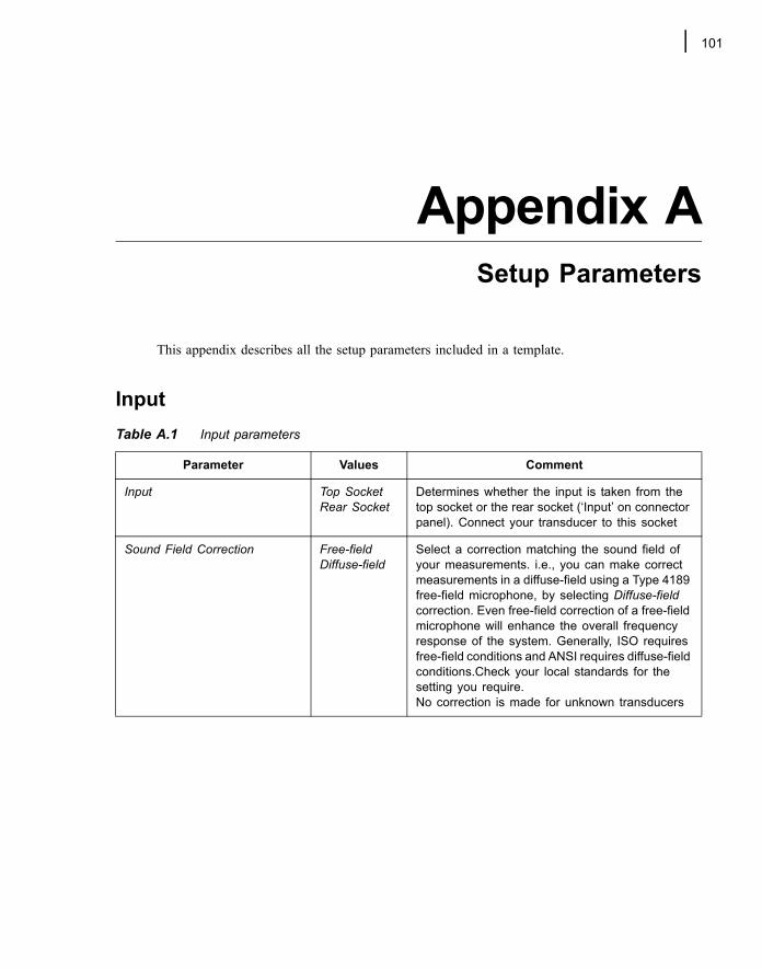
101
Appendix ASetup Parameters
This appendix describes all the setup parameters included in a template.
InputTable A.1 Input parameters
Parameter Values Comment
Input Top SocketRear Socket
Determines whether the input is taken from the top socket or the rear socket (�Input� on connector panel). Connect your transducer to this socket
Sound Field Correction Free-fieldDiffuse-field
Select a correction matching the sound field of your measurements. i.e., you can make correct measurements in a diffuse-field using a Type 4189 free-field microphone, by selecting Diffuse-field correction. Even free-field correction of a free-field microphone will enhance the overall frequency response of the system. Generally, ISO requires free-field conditions and ANSI requires diffuse-field conditions.Check your local standards for the setting you require.No correction is made for unknown transducers
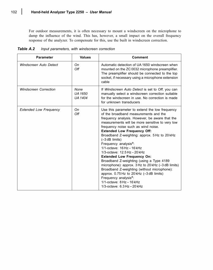
Hand-held Analyzer Type 2250 � User Manual102
For outdoor measurements, it is often necessary to mount a windscreen on the microphone todamp the influence of the wind. This has, however, a small impact on the overall frequencyresponse of the analyzer. To compensate for this, use the built in windscreen correction.
Table A.2 Input parameters, with windscreen correction
Parameter Values Comment
Windscreen Auto Detect OnOff
Automatic detection of UA 1650 windscreen when mounted on the ZC 0032 microphone preamplifier. The preamplifier should be connected to the top socket, if necessary using a microphone extension cable
Windscreen Correction NoneUA 1650 UA 1404
If Windscreen Auto Detect is set to Off, you can manually select a windscreen correction suitable for the windscreen in use. No correction is made for unknown transducers
Extended Low Frequency OnOff
Use this parameter to extend the low frequency of the broadband measurements and the frequency analysis. However, be aware that the measurements will be more sensitive to very low frequency noise such as wind noise. Extended Low Frequency Off:Broadband Z-weighting: approx. 5 Hz to 20 kHz (�3 dB limits)Frequency analysisa: 1/1-octave: 16 Hz � 16 kHz 1/3-octave: 12.5 Hz � 20 kHz Extended Low Frequency On:Broadband Z-weighting (using a Type 4189 microphone): approx. 3 Hz to 20 kHz (�3 dB limits)Broadband Z-weighting (without microphone): approx. 0.75 Hz to 20 kHz (�3 dB limits)Frequency analysisa: 1/1-octave: 8 Hz � 16 kHz1/3-octave: 6.3 Hz � 20 kHz
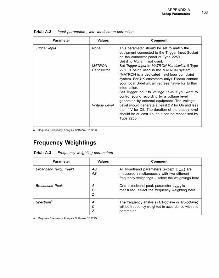
APPENDIX ASetup Parameters 103
Frequency Weightings
Trigger Input None
MATRON Handswitch
Voltage Level
This parameter should be set to match the equipment connected to the Trigger Input Socket on the connector panel of Type 2250.Set it to None, if not used.Set Trigger Input to MATRON Handswitch if Type 2250 is being used in the MATRON system. (MATRON is a dedicated neighbour complaint system. For UK customers only). Please contact your local Brüel & Kjær representative for further information.Set Trigger input to Voltage Level if you want to control sound recording by a voltage level generated by external equipment. The Voltage Level should generate at least 2 V for On and less than 1 V for Off. The duration of the steady level should be at least 1 s, so it can be recognised by Type 2250
a. Requires Frequency Analysis Software BZ 7223
Table A.3 Frequency weighting parameters
Parameter Values Comment
Broadband (excl. Peak) AC AZ
All broadband parameters (except Lpeak) are measured simultaneously with two different frequency weightings � select the weightings here
Broadband Peak ACZ
One broadband peak parameter Lpeak is measured, select the frequency weighting here
Spectruma
a. Requires Frequency Analysis Software BZ 7223
ACZ
The frequency analysis (1/1-octave or 1/3-octave) will be frequency weighted in accordance with this parameter
Table A.2 Input parameters, with windscreen correction
Parameter Values Comment
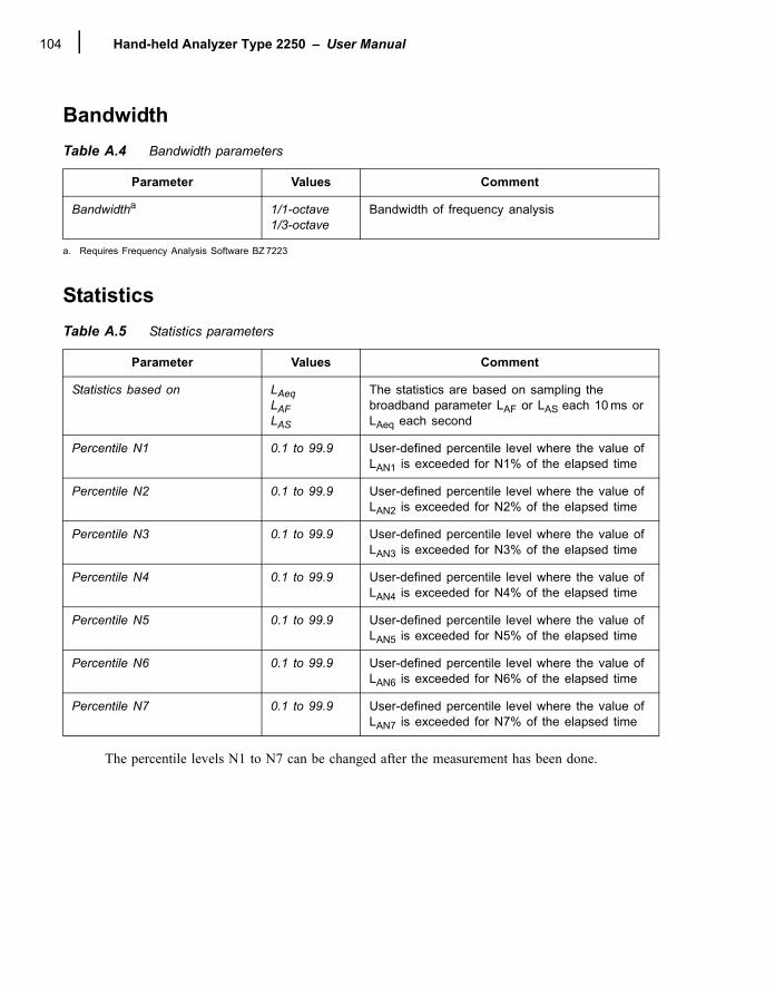
Hand-held Analyzer Type 2250 � User Manual104
Bandwidth
Statistics
The percentile levels N1 to N7 can be changed after the measurement has been done.
Table A.4 Bandwidth parameters
Parameter Values Comment
Bandwidtha
a. Requires Frequency Analysis Software BZ 7223
1/1-octave1/3-octave
Bandwidth of frequency analysis
Table A.5 Statistics parameters
Parameter Values Comment
Statistics based on LAeqLAFLAS
The statistics are based on sampling the broadband parameter LAF or LAS each 10 ms or LAeq each second
Percentile N1 0.1 to 99.9 User-defined percentile level where the value of LAN1 is exceeded for N1% of the elapsed time
Percentile N2 0.1 to 99.9 User-defined percentile level where the value of LAN2 is exceeded for N2% of the elapsed time
Percentile N3 0.1 to 99.9 User-defined percentile level where the value of LAN3 is exceeded for N3% of the elapsed time
Percentile N4 0.1 to 99.9 User-defined percentile level where the value of LAN4 is exceeded for N4% of the elapsed time
Percentile N5 0.1 to 99.9 User-defined percentile level where the value of LAN5 is exceeded for N5% of the elapsed time
Percentile N6 0.1 to 99.9 User-defined percentile level where the value of LAN6 is exceeded for N6% of the elapsed time
Percentile N7 0.1 to 99.9 User-defined percentile level where the value of LAN7 is exceeded for N7% of the elapsed time
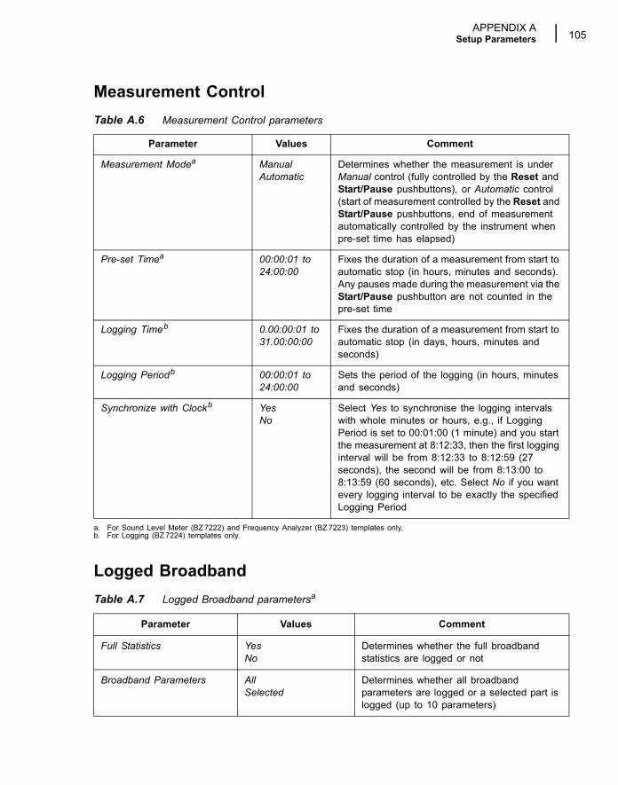
APPENDIX ASetup Parameters 105
Measurement Control
Logged Broadband
Table A.6 Measurement Control parameters
Parameter Values Comment
Measurement Modea
a. For Sound Level Meter (BZ 7222) and Frequency Analyzer (BZ 7223) templates only.
ManualAutomatic
Determines whether the measurement is under Manual control (fully controlled by the Reset and Start/Pause pushbuttons), or Automatic control (start of measurement controlled by the Reset and Start/Pause pushbuttons, end of measurement automatically controlled by the instrument when pre-set time has elapsed)
Pre-set Timea 00:00:01 to 24:00:00
Fixes the duration of a measurement from start to automatic stop (in hours, minutes and seconds). Any pauses made during the measurement via the Start/Pause pushbutton are not counted in the pre-set time
Logging Timeb
b. For Logging (BZ 7224) templates only.
0.00:00:01 to 31.00:00:00
Fixes the duration of a measurement from start to automatic stop (in days, hours, minutes and seconds)
Logging Periodb 00:00:01 to 24:00:00
Sets the period of the logging (in hours, minutes and seconds)
Synchronize with Clockb YesNo
Select Yes to synchronise the logging intervals with whole minutes or hours, e.g., if Logging Period is set to 00:01:00 (1 minute) and you start the measurement at 8:12:33, then the first logging interval will be from 8:12:33 to 8:12:59 (27 seconds), the second will be from 8:13:00 to 8:13:59 (60 seconds), etc. Select No if you want every logging interval to be exactly the specified Logging Period
Table A.7 Logged Broadband parametersa
Parameter Values Comment
Full Statistics YesNo
Determines whether the full broadband statistics are logged or not
Broadband Parameters AllSelected
Determines whether all broadband parameters are logged or a selected part is logged (up to 10 parameters)
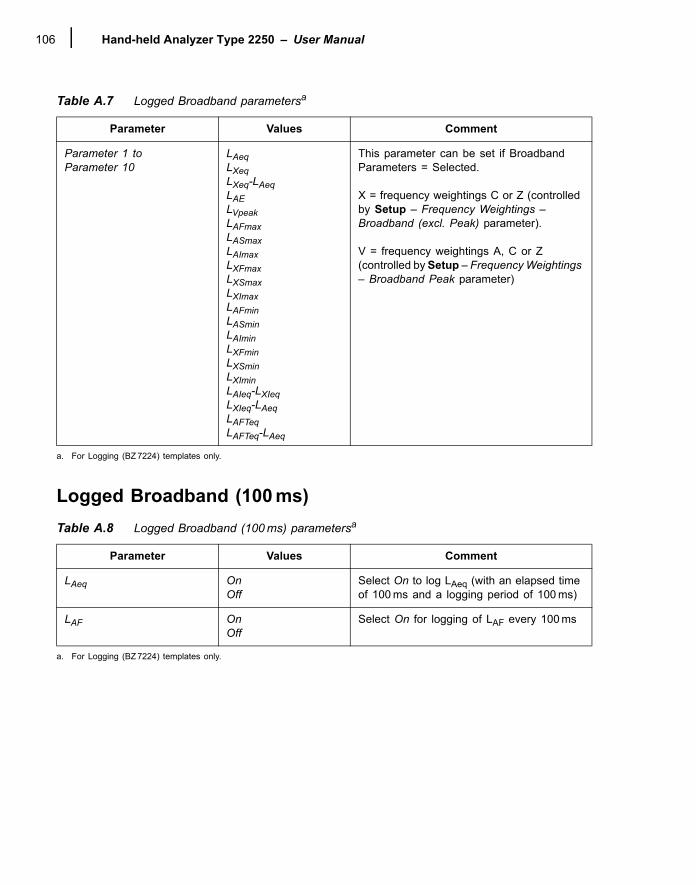
Hand-held Analyzer Type 2250 � User Manual106
Logged Broadband (100 ms)
Parameter 1 to Parameter 10
LAeqLXeqLXeq-LAeqLAELVpeakLAFmaxLASmaxLAImaxLXFmaxLXSmaxLXImaxLAFminLASminLAIminLXFminLXSminLXIminLAIeq-LXIeqLXIeq-LAeqLAFTeqLAFTeq-LAeq
This parameter can be set if Broadband Parameters = Selected.
X = frequency weightings C or Z (controlled by Setup � Frequency Weightings � Broadband (excl. Peak) parameter).
V = frequency weightings A, C or Z (controlled by Setup � Frequency Weightings � Broadband Peak parameter)
a. For Logging (BZ 7224) templates only.
Table A.8 Logged Broadband (100 ms) parametersa
a. For Logging (BZ 7224) templates only.
Parameter Values Comment
LAeq OnOff
Select On to log LAeq (with an elapsed time of 100 ms and a logging period of 100 ms)
LAF OnOff
Select On for logging of LAF every 100 ms
Table A.7 Logged Broadband parametersa
Parameter Values Comment
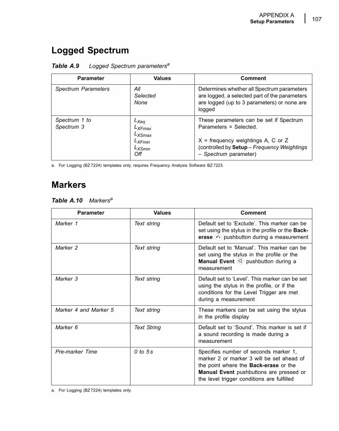
APPENDIX ASetup Parameters 107
Logged Spectrum
Markers
Table A.9 Logged Spectrum parametersa
a. For Logging (BZ 7224) templates only, requires Frequency Analysis Software BZ 7223.
Parameter Values Comment
Spectrum Parameters AllSelectedNone
Determines whether all Spectrum parameters are logged, a selected part of the parameters are logged (up to 3 parameters) or none are logged
Spectrum 1 to Spectrum 3
LXeqLXFmaxLXSmaxLXFminLXSminOff
These parameters can be set if Spectrum Parameters = Selected.
X = frequency weightings A, C or Z (controlled by Setup � Frequency Weightings � Spectrum parameter)
Table A.10 Markersa
a. For Logging (BZ 7224) templates only.
Parameter Values Comment
Marker 1 Text string Default set to �Exclude�. This marker can be set using the stylus in the profile or the Back-erase pushbutton during a measurement
Marker 2 Text string Default set to �Manual�. This marker can be set using the stylus in the profile or the Manual Event pushbutton during a measurement
Marker 3 Text string Default set to �Level�. This marker can be set using the stylus in the profile, or if the conditions for the Level Trigger are met during a measurement
Marker 4 and Marker 5 Text string These markers can be set using the stylus in the profile display
Marker 6 Text String Default set to �Sound�. This marker is set if a sound recording is made during a measurement
Pre-marker Time 0 to 5 s Specifies number of seconds marker 1, marker 2 or marker 3 will be set ahead of the point where the Back-erase or the Manual Event pushbuttons are pressed or the level trigger conditions are fulfilled
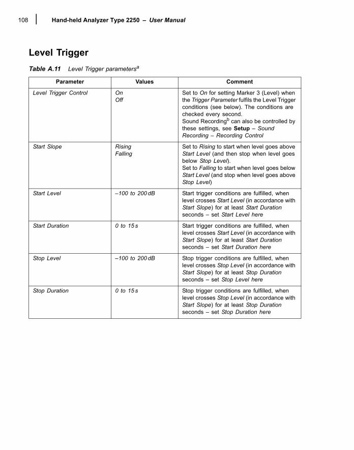
Hand-held Analyzer Type 2250 � User Manual108
Level TriggerTable A.11 Level Trigger parametersa
Parameter Values Comment
Level Trigger Control OnOff
Set to On for setting Marker 3 (Level) when the Trigger Parameter fulfils the Level Trigger conditions (see below). The conditions are checked every second.Sound Recordingb can also be controlled by these settings, see Setup � Sound Recording � Recording Control
Start Slope RisingFalling
Set to Rising to start when level goes above Start Level (and then stop when level goes below Stop Level).Set to Falling to start when level goes below Start Level (and stop when level goes above Stop Level)
Start Level �100 to 200 dB Start trigger conditions are fulfilled, when level crosses Start Level (in accordance with Start Slope) for at least Start Duration seconds � set Start Level here
Start Duration 0 to 15 s Start trigger conditions are fulfilled, when level crosses Start Level (in accordance with Start Slope) for at least Start Duration seconds � set Start Duration here
Stop Level �100 to 200 dB Stop trigger conditions are fulfilled, when level crosses Stop Level (in accordance with Start Slope) for at least Stop Duration seconds � set Stop Level here
Stop Duration 0 to 15 s Stop trigger conditions are fulfilled, when level crosses Stop Level (in accordance with Start Slope) for at least Stop Duration seconds � set Stop Duration here
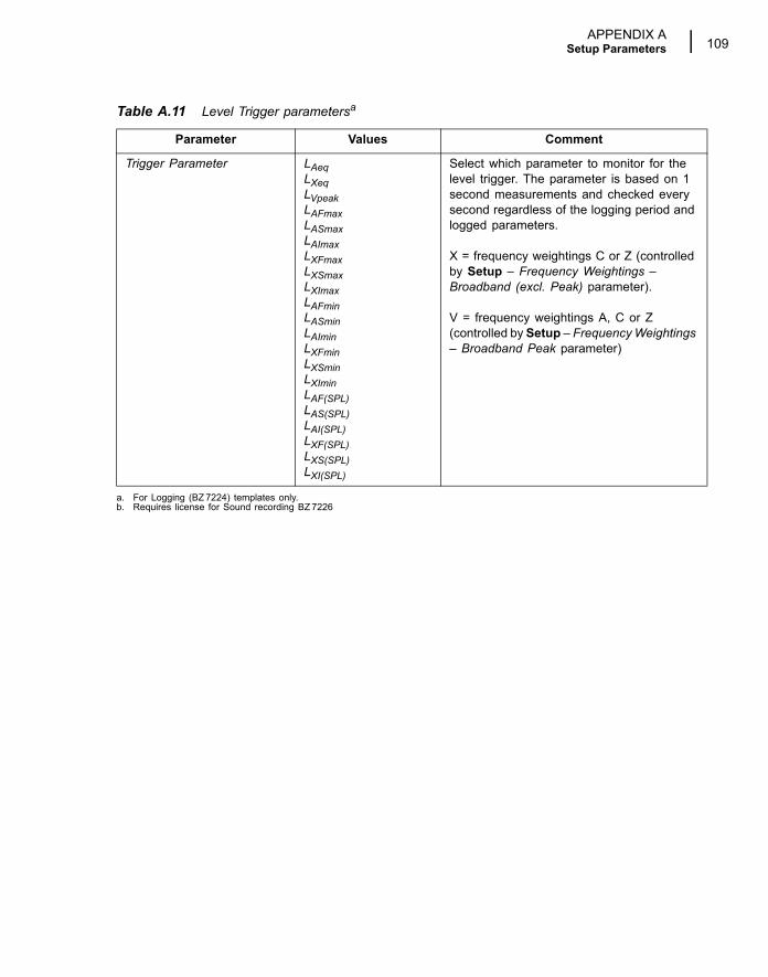
APPENDIX ASetup Parameters 109
Trigger Parameter LAeqLXeqLVpeak LAFmax LASmax LAImax LXFmax LXSmax LXImax LAFmin LASmin LAImin LXFmin LXSmin LXImin LAF(SPL) LAS(SPL)LAI(SPL)LXF(SPL)LXS(SPL)LXI(SPL)
Select which parameter to monitor for the level trigger. The parameter is based on 1 second measurements and checked every second regardless of the logging period and logged parameters.
X = frequency weightings C or Z (controlled by Setup � Frequency Weightings � Broadband (excl. Peak) parameter).
V = frequency weightings A, C or Z (controlled by Setup � Frequency Weightings � Broadband Peak parameter)
a. For Logging (BZ 7224) templates only.b. Requires license for Sound recording BZ 7226
Table A.11 Level Trigger parametersa
Parameter Values Comment
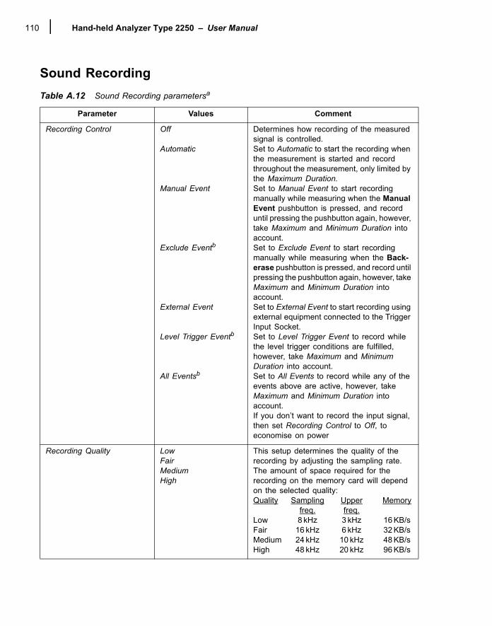
Hand-held Analyzer Type 2250 � User Manual110
Sound RecordingTable A.12 Sound Recording parametersa
Parameter Values Comment
Recording Control Off
Automatic
Manual Event
Exclude Eventb
External Event
Level Trigger Eventb
All Eventsb
Determines how recording of the measured signal is controlled.Set to Automatic to start the recording when the measurement is started and record throughout the measurement, only limited by the Maximum Duration.Set to Manual Event to start recording manually while measuring when the Manual Event pushbutton is pressed, and record until pressing the pushbutton again, however, take Maximum and Minimum Duration into account.Set to Exclude Event to start recording manually while measuring when the Back-erase pushbutton is pressed, and record until pressing the pushbutton again, however, take Maximum and Minimum Duration into account.Set to External Event to start recording using external equipment connected to the Trigger Input Socket.Set to Level Trigger Event to record while the level trigger conditions are fulfilled, however, take Maximum and Minimum Duration into account.Set to All Events to record while any of the events above are active, however, take Maximum and Minimum Duration into account.If you don�t want to record the input signal, then set Recording Control to Off, to economise on power
Recording Quality LowFairMediumHigh
This setup determines the quality of the recording by adjusting the sampling rate.The amount of space required for the recording on the memory card will depend on the selected quality:Quality Sampling Upper Memory
freq. freq.Low 8 kHz 3 kHz 16 KB/s Fair 16 kHz 6 kHz 32 KB/sMedium 24 kHz 10 kHz 48 KB/sHigh 48 kHz 20 kHz 96 KB/s
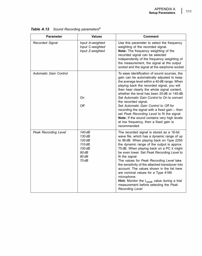
APPENDIX ASetup Parameters 111
Recorded Signal Input A-weightedInput C-weightedInput Z-weighted
Use this parameter to select the frequency weighting of the recorded signal.Note: The frequency weighting of the recorded signal can be selected independently of the frequency weighting of the measurement, the signal at the output socket and the signal at the earphone socket
Automatic Gain Control
On
Off
To ease identification of sound sources, the gain can be automatically adjusted to keep the average level within a 40 dB range. When playing back the recorded signal, you will then hear clearly the whole signal content, whether the level has been 20 dB or 140 dB.Set Automatic Gain Control to On to convert the recorded signal.Set Automatic Gain Control to Off for recording the signal with a fixed gain � then set Peak Recording Level to fit the signalNote: If the sound contains very high levels at low frequency, then a fixed gain is recommended
Peak Recording Level 140 dB130 dB120 dB110 dB100 dB90 dB80 dB70 dB
The recorded signal is stored as a 16-bit wave file, which has a dynamic range of up to 96 dB. When playing back on Type 2250 the dynamic range of the output is approx. 75 dB. When playing back on a PC it might be even lower. Set Peak Recording Level to fit the signal.The values for Peak Recording Level take the sensitivity of the attached transducer into account. The values shown in the list here are nominal values for a Type 4189 microphone.Hint: Monitor the Lpeak value during a trial measurement before selecting the Peak Recording Level
Table A.12 Sound Recording parametersa
Parameter Values Comment
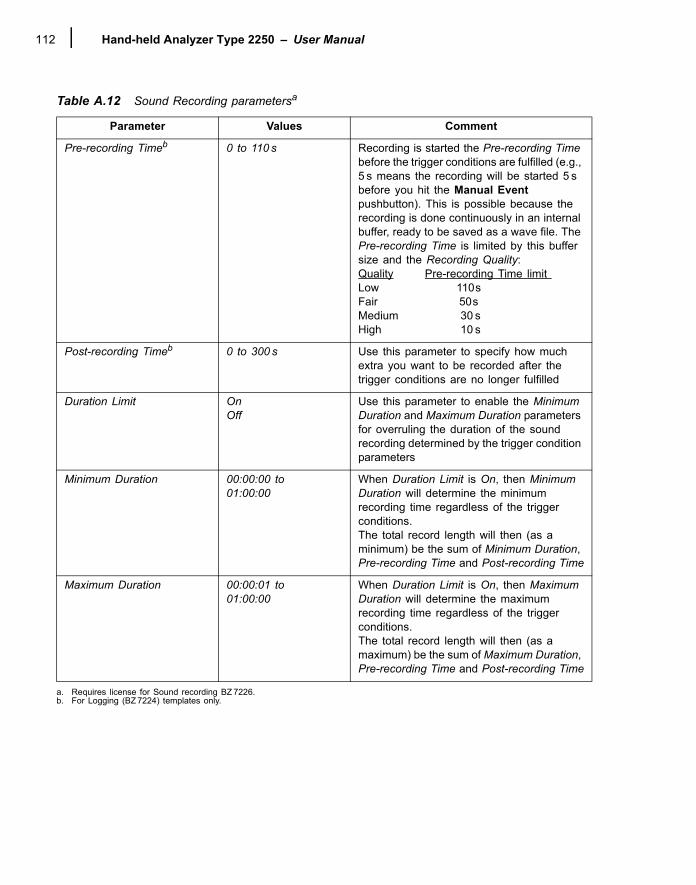
Hand-held Analyzer Type 2250 � User Manual112
Pre-recording Timeb 0 to 110 s Recording is started the Pre-recording Time before the trigger conditions are fulfilled (e.g., 5 s means the recording will be started 5 s before you hit the Manual Event pushbutton). This is possible because the recording is done continuously in an internal buffer, ready to be saved as a wave file. The Pre-recording Time is limited by this buffer size and the Recording Quality:Quality Pre-recording Time limit Low 110 s Fair 50 s Medium 30 sHigh 10 s
Post-recording Timeb 0 to 300 s Use this parameter to specify how much extra you want to be recorded after the trigger conditions are no longer fulfilled
Duration Limit OnOff
Use this parameter to enable the Minimum Duration and Maximum Duration parameters for overruling the duration of the sound recording determined by the trigger condition parameters
Minimum Duration 00:00:00 to01:00:00
When Duration Limit is On, then Minimum Duration will determine the minimum recording time regardless of the trigger conditions.The total record length will then (as a minimum) be the sum of Minimum Duration, Pre-recording Time and Post-recording Time
Maximum Duration 00:00:01 to01:00:00
When Duration Limit is On, then Maximum Duration will determine the maximum recording time regardless of the trigger conditions.The total record length will then (as a maximum) be the sum of Maximum Duration, Pre-recording Time and Post-recording Time
a. Requires license for Sound recording BZ 7226.b. For Logging (BZ 7224) templates only.
Table A.12 Sound Recording parametersa
Parameter Values Comment
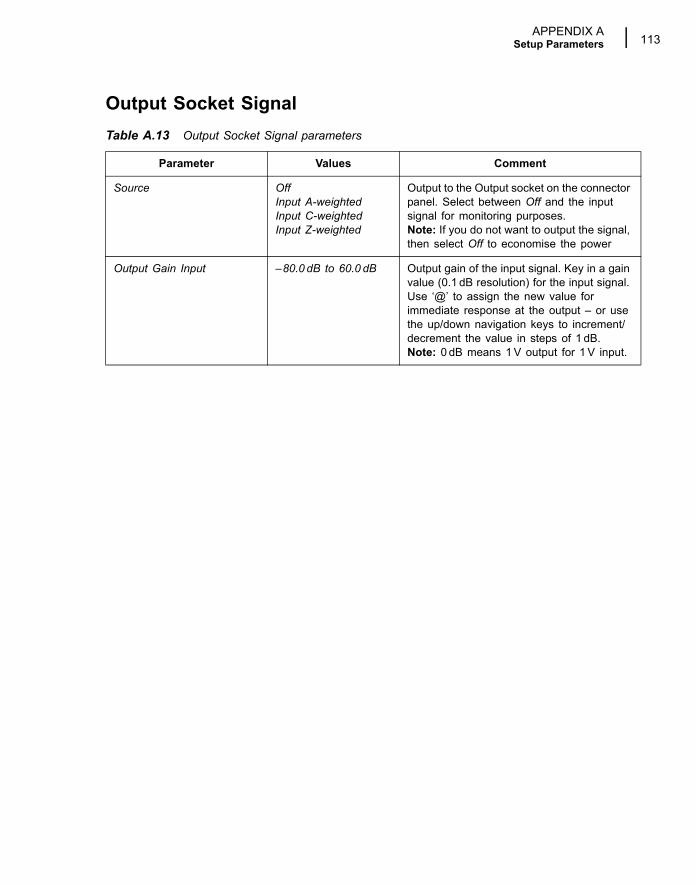
APPENDIX ASetup Parameters 113
Output Socket SignalTable A.13 Output Socket Signal parameters
Parameter Values Comment
Source OffInput A-weightedInput C-weightedInput Z-weighted
Output to the Output socket on the connector panel. Select between Off and the input signal for monitoring purposes. Note: If you do not want to output the signal, then select Off to economise the power
Output Gain Input �80.0 dB to 60.0 dB Output gain of the input signal. Key in a gain value (0.1 dB resolution) for the input signal. Use �@� to assign the new value for immediate response at the output � or use the up/down navigation keys to increment/decrement the value in steps of 1 dB. Note: 0 dB means 1 V output for 1 V input.

Hand-held Analyzer Type 2250 � User Manual114
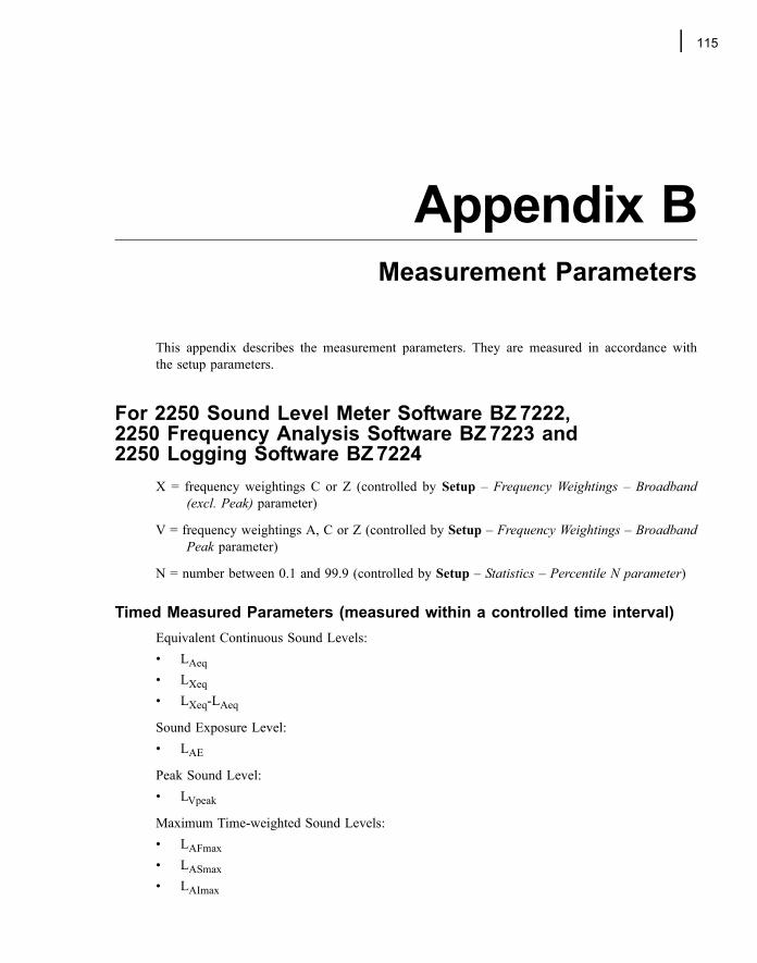
115
Appendix BMeasurement Parameters
This appendix describes the measurement parameters. They are measured in accordance withthe setup parameters.
For 2250 Sound Level Meter Software BZ 7222, 2250 Frequency Analysis Software BZ 7223 and 2250 Logging Software BZ 7224
X = frequency weightings C or Z (controlled by Setup � Frequency Weightings � Broadband(excl. Peak) parameter)
V = frequency weightings A, C or Z (controlled by Setup � Frequency Weightings � BroadbandPeak parameter)
N = number between 0.1 and 99.9 (controlled by Setup � Statistics � Percentile N parameter)
Timed Measured Parameters (measured within a controlled time interval)Equivalent Continuous Sound Levels:� LAeq� LXeq� LXeq-LAeq
Sound Exposure Level:� LAE
Peak Sound Level:� LVpeak
Maximum Time-weighted Sound Levels:� LAFmax� LASmax� LAImax
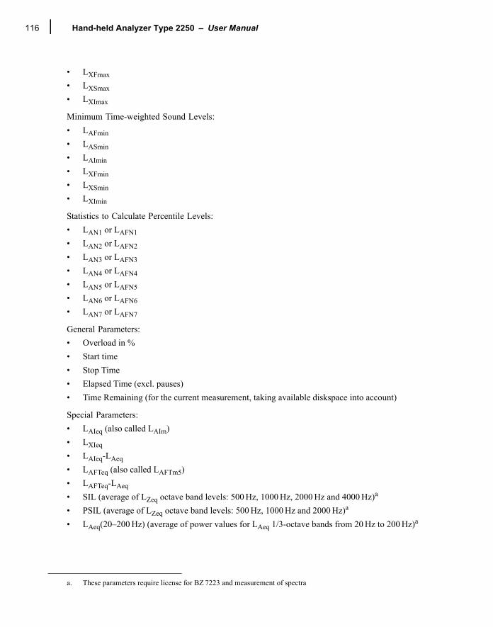
Hand-held Analyzer Type 2250 � User Manual116
� LXFmax� LXSmax� LXImax
Minimum Time-weighted Sound Levels:� LAFmin� LASmin� LAImin� LXFmin� LXSmin� LXImin
Statistics to Calculate Percentile Levels:� LAN1 or LAFN1� LAN2 or LAFN2� LAN3 or LAFN3� LAN4 or LAFN4� LAN5 or LAFN5� LAN6 or LAFN6� LAN7 or LAFN7
General Parameters:� Overload in %� Start time� Stop Time� Elapsed Time (excl. pauses)� Time Remaining (for the current measurement, taking available diskspace into account)
Special Parameters:� LAIeq (also called LAIm)� LXIeq� LAIeq-LAeq� LAFTeq (also called LAFTm5)� LAFTeq-LAeq� SIL (average of LZeq octave band levels: 500 Hz, 1000 Hz, 2000 Hz and 4000 Hz)a
� PSIL (average of LZeq octave band levels: 500 Hz, 1000 Hz and 2000 Hz)a
� LAeq(20�200 Hz) (average of power values for LAeq 1/3-octave bands from 20 Hz to 200 Hz)a
a. These parameters require license for BZ 7223 and measurement of spectra
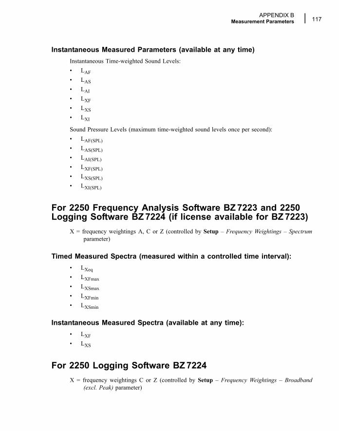
APPENDIX BMeasurement Parameters 117
Instantaneous Measured Parameters (available at any time)Instantaneous Time-weighted Sound Levels:� LAF� LAS� LAI� LXF� LXS� LXI
Sound Pressure Levels (maximum time-weighted sound levels once per second):� LAF(SPL)� LAS(SPL)� LAI(SPL)� LXF(SPL)� LXS(SPL)� LXI(SPL)
For 2250 Frequency Analysis Software BZ 7223 and 2250 Logging Software BZ 7224 (if license available for BZ 7223)
X = frequency weightings A, C or Z (controlled by Setup � Frequency Weightings � Spectrumparameter)
Timed Measured Spectra (measured within a controlled time interval):� LXeq� LXFmax� LXSmax� LXFmin� LXSmin
Instantaneous Measured Spectra (available at any time):� LXF� LXS
For 2250 Logging Software BZ 7224X = frequency weightings C or Z (controlled by Setup � Frequency Weightings � Broadband
(excl. Peak) parameter)
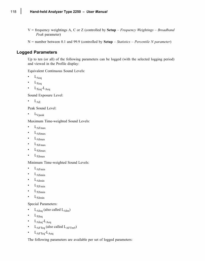
Hand-held Analyzer Type 2250 � User Manual118
V = frequency weightings A, C or Z (controlled by Setup � Frequency Weightings � BroadbandPeak parameter)
N = number between 0.1 and 99.9 (controlled by Setup � Statistics � Percentile N parameter)
Logged ParametersUp to ten (or all) of the following parameters can be logged (with the selected logging period)and viewed in the Profile display:
Equivalent Continuous Sound Levels:� LAeq� LXeq� LXeq-LAeq
Sound Exposure Level:� LAE
Peak Sound Level:� LVpeak
Maximum Time-weighted Sound Levels:� LAFmax� LASmax� LAImax� LXFmax� LXSmax� LXImax
Minimum Time-weighted Sound Levels:� LAFmin� LASmin� LAImin� LXFmin� LXSmin� LXImin
Special Parameters:� LAIeq (also called LAIm)� LXIeq� LAIeq-LAeq� LAFTeq (also called LAFTm5)� LAFTeq-LAeq
The following parameters are available per set of logged parameters:
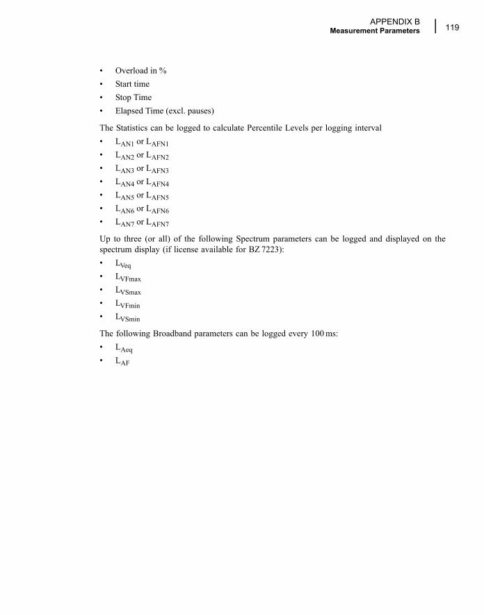
APPENDIX BMeasurement Parameters 119
� Overload in %� Start time� Stop Time� Elapsed Time (excl. pauses)
The Statistics can be logged to calculate Percentile Levels per logging interval� LAN1 or LAFN1� LAN2 or LAFN2� LAN3 or LAFN3� LAN4 or LAFN4� LAN5 or LAFN5� LAN6 or LAFN6� LAN7 or LAFN7
Up to three (or all) of the following Spectrum parameters can be logged and displayed on thespectrum display (if license available for BZ 7223):� LVeq� LVFmax� LVSmax� LVFmin� LVSmin
The following Broadband parameters can be logged every 100 ms:� LAeq� LAF

Hand-held Analyzer Type 2250 � User Manual120
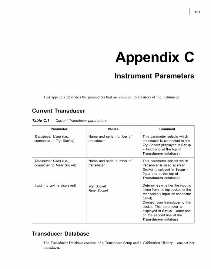
121
Appendix CInstrument Parameters
This appendix describes the parameters that are common to all users of the instrument.
Current Transducer
Transducer DatabaseThe Transducer Database consists of a Transducer Setup and a Calibration History � one set pertransducer.
Table C.1 Current Transducer parameters
Parameter Values Comment
Transducer Used (i.e., connected to Top Socket)
Name and serial number of transducer
This parameter selects which transducer is connected to the Top Socket (displayed in Setup � Input and at the top of Transducers database)
Transducer Used (i.e., connected to Rear Socket)
Name and serial number of transducer
This parameter selects which transducer is used at Rear Socket (displayed in Setup � Input and at the top of Transducers database)
Input (no text is displayed) Top Socket Rear Socket
Determines whether the input is taken from the top socket, or the rear socket (�Input� on connector panel). Connect your transducer to this socket. This parameter is displayed in Setup � Input and on the second line of the Transducers database
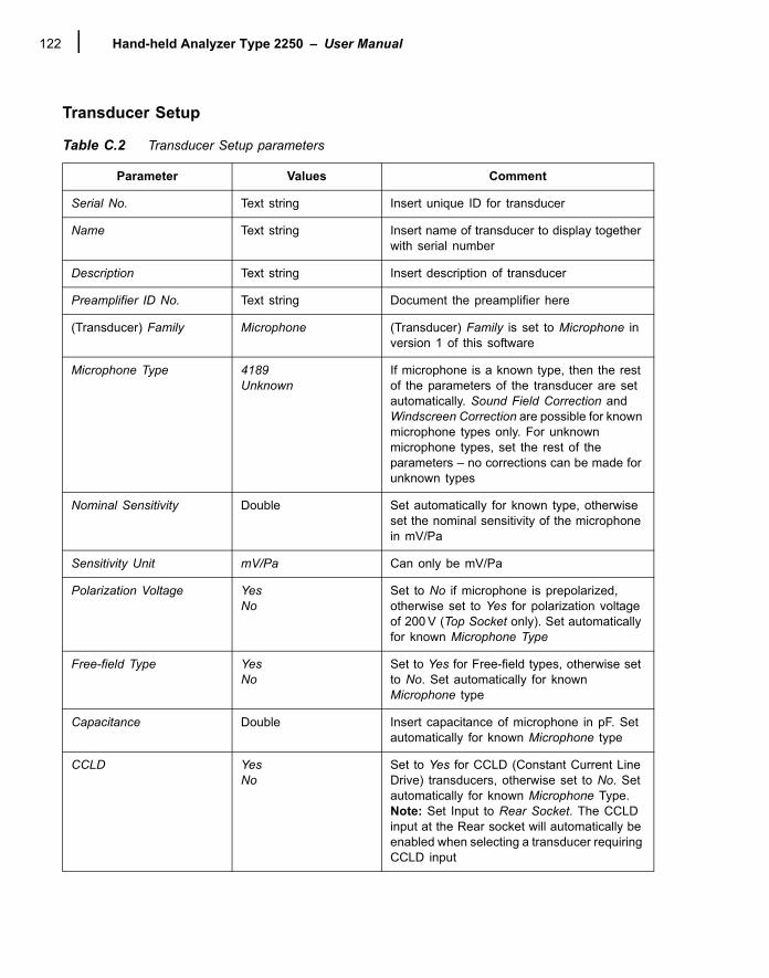
Hand-held Analyzer Type 2250 � User Manual122
Transducer Setup
Table C.2 Transducer Setup parameters
Parameter Values Comment
Serial No. Text string Insert unique ID for transducer
Name Text string Insert name of transducer to display together with serial number
Description Text string Insert description of transducer
Preamplifier ID No. Text string Document the preamplifier here
(Transducer) Family Microphone (Transducer) Family is set to Microphone in version 1 of this software
Microphone Type 4189Unknown
If microphone is a known type, then the rest of the parameters of the transducer are set automatically. Sound Field Correction and Windscreen Correction are possible for known microphone types only. For unknown microphone types, set the rest of the parameters � no corrections can be made for unknown types
Nominal Sensitivity Double Set automatically for known type, otherwise set the nominal sensitivity of the microphone in mV/Pa
Sensitivity Unit mV/Pa Can only be mV/Pa
Polarization Voltage YesNo
Set to No if microphone is prepolarized, otherwise set to Yes for polarization voltage of 200 V (Top Socket only). Set automatically for known Microphone Type
Free-field Type YesNo
Set to Yes for Free-field types, otherwise set to No. Set automatically for known Microphone type
Capacitance Double Insert capacitance of microphone in pF. Set automatically for known Microphone type
CCLD YesNo
Set to Yes for CCLD (Constant Current Line Drive) transducers, otherwise set to No. Set automatically for known Microphone Type.Note: Set Input to Rear Socket. The CCLD input at the Rear socket will automatically be enabled when selecting a transducer requiring CCLD input
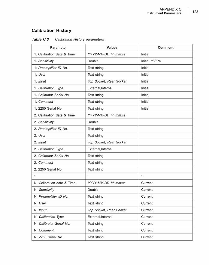
APPENDIX CInstrument Parameters 123
Calibration History
Table C.3 Calibration History parameters
Parameter Values Comment
1. Calibration date & Time YYYY-MM-DD hh:mm:ss Initial
1. Sensitivity Double Initial mV/Pa
1. Preamplifier ID No. Text string Initial
1. User Text string Initial
1. Input Top Socket, Rear Socket Initial
1. Calibration Type External,Internal Initial
1. Calibrator Serial No. Text string Initial
1. Comment Text string Initial
1. 2250 Serial No. Text string Initial
2. Calibration date & Time YYYY-MM-DD hh:mm:ss
2. Sensitivity Double
2. Preamplifier ID No. Text string
2. User Text string
2. Input Top Socket, Rear Socket
2. Calibration Type External,Internal
2. Calibrator Serial No. Text string
2. Comment Text string
2. 2250 Serial No. Text string
: : :
N. Calibration date & Time YYYY-MM-DD hh:mm:ss Current
N. Sensitivity Double Current
N. Preamplifier ID No. Text string Current
N. User Text string Current
N. Input Top Socket, Rear Socket Current
N. Calibration Type External,Internal Current
N. Calibrator Serial No. Text string Current
N. Comment Text string Current
N. 2250 Serial No. Text string Current
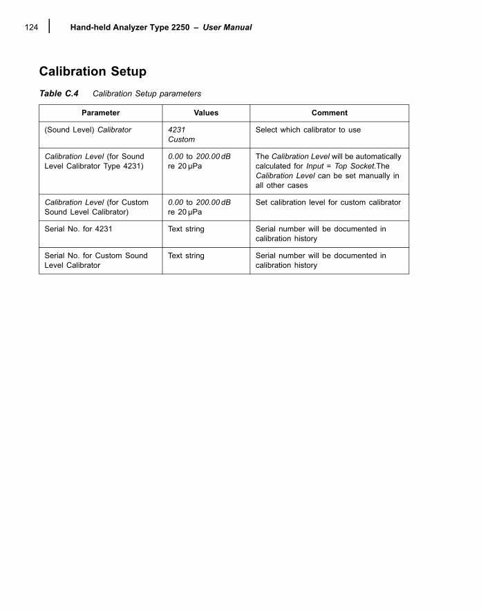
Hand-held Analyzer Type 2250 � User Manual124
Calibration SetupTable C.4 Calibration Setup parameters
Parameter Values Comment
(Sound Level) Calibrator 4231Custom
Select which calibrator to use
Calibration Level (for Sound Level Calibrator Type 4231)
0.00 to 200.00 dB re 20 µPa
The Calibration Level will be automatically calculated for Input = Top Socket.The Calibration Level can be set manually in all other cases
Calibration Level (for Custom Sound Level Calibrator)
0.00 to 200.00 dB re 20 µPa
Set calibration level for custom calibrator
Serial No. for 4231 Text string Serial number will be documented in calibration history
Serial No. for Custom Sound Level Calibrator
Text string Serial number will be documented in calibration history
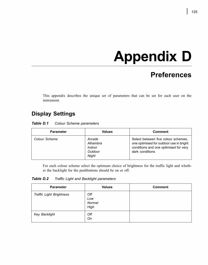
125
Appendix DPreferences
This appendix describes the unique set of parameters that can be set for each user on theinstrument.
Display Settings
For each colour scheme select the optimum choice of brightness for the traffic light and wheth-er the backlight for the pushbuttons should be on or off.
Table D.1 Colour Scheme parameters
Parameter Values Comment
Colour Scheme ArcadeAlhambraIndoorOutdoorNight
Select between five colour schemes, one optimised for outdoor use in bright conditions and one optimised for very dark conditions
Table D.2 Traffic Light and Backlight parameters
Parameter Values Comment
Traffic Light Brightness Off Low Normal High
Key Backlight Off On
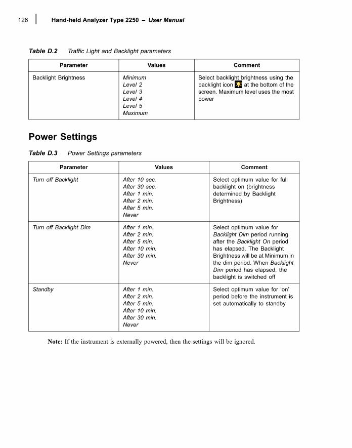
Hand-held Analyzer Type 2250 � User Manual126
Power Settings
Note: If the instrument is externally powered, then the settings will be ignored.
Backlight Brightness MinimumLevel 2 Level 3 Level 4 Level 5 Maximum
Select backlight brightness using the backlight icon at the bottom of the screen. Maximum level uses the most power
Table D.3 Power Settings parameters
Parameter Values Comment
Turn off Backlight After 10 sec.After 30 sec.After 1 min.After 2 min.After 5 min.Never
Select optimum value for full backlight on (brightness determined by Backlight Brightness)
Turn off Backlight Dim After 1 min.After 2 min.After 5 min.After 10 min.After 30 min.Never
Select optimum value for Backlight Dim period running after the Backlight On period has elapsed. The Backlight Brightness will be at Minimum in the dim period. When Backlight Dim period has elapsed, the backlight is switched off
Standby After 1 min.After 2 min.After 5 min.After 10 min.After 30 min.Never
Select optimum value for �on� period before the instrument is set automatically to standby
Table D.2 Traffic Light and Backlight parameters
Parameter Values Comment
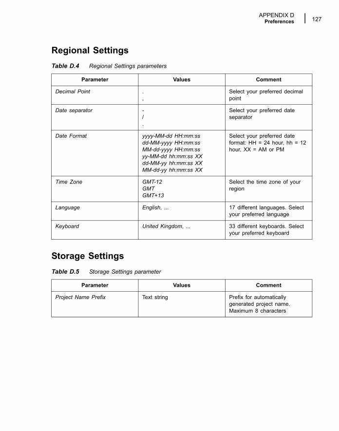
APPENDIX DPreferences 127
Regional Settings
Storage Settings
Table D.4 Regional Settings parameters
Parameter Values Comment
Decimal Point .,
Select your preferred decimal point
Date separator -/.
Select your preferred date separator
Date Format yyyy-MM-dd HH:mm:ssdd-MM-yyyy HH:mm:ssMM-dd-yyyy HH:mm:ssyy-MM-dd hh:mm:ss XXdd-MM-yy hh:mm:ss XXMM-dd-yy hh:mm:ss XX
Select your preferred date format: HH = 24 hour, hh = 12 hour, XX = AM or PM
Time Zone GMT-12GMTGMT+13
Select the time zone of your region
Language English, ... 17 different languages. Select your preferred language
Keyboard United Kingdom, ... 33 different keyboards. Select your preferred keyboard
Table D.5 Storage Settings parameter
Parameter Values Comment
Project Name Prefix Text string Prefix for automatically generated project name. Maximum 8 characters
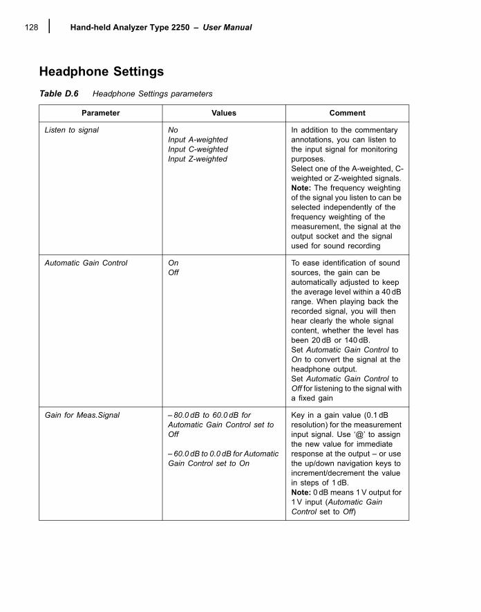
Hand-held Analyzer Type 2250 � User Manual128
Headphone SettingsTable D.6 Headphone Settings parameters
Parameter Values Comment
Listen to signal NoInput A-weightedInput C-weightedInput Z-weighted
In addition to the commentary annotations, you can listen to the input signal for monitoring purposes.Select one of the A-weighted, C-weighted or Z-weighted signals. Note: The frequency weighting of the signal you listen to can be selected independently of the frequency weighting of the measurement, the signal at the output socket and the signal used for sound recording
Automatic Gain Control OnOff
To ease identification of sound sources, the gain can be automatically adjusted to keep the average level within a 40 dB range. When playing back the recorded signal, you will then hear clearly the whole signal content, whether the level has been 20 dB or 140 dB.Set Automatic Gain Control to On to convert the signal at the headphone output.Set Automatic Gain Control to Off for listening to the signal with a fixed gain
Gain for Meas.Signal � 80.0 dB to 60.0 dB for Automatic Gain Control set to Off
� 60.0 dB to 0.0 dB for Automatic Gain Control set to On
Key in a gain value (0.1 dB resolution) for the measurement input signal. Use �@� to assign the new value for immediate response at the output � or use the up/down navigation keys to increment/decrement the value in steps of 1 dB.Note: 0 dB means 1 V output for 1 V input (Automatic Gain Control set to Off)
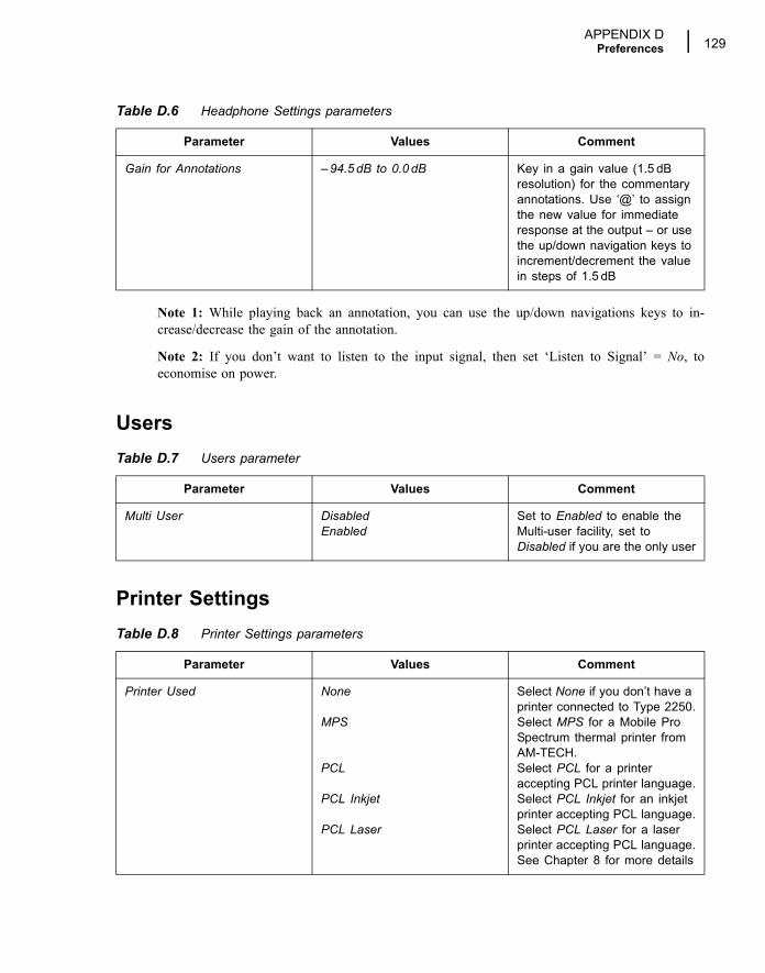
APPENDIX DPreferences 129
Note 1: While playing back an annotation, you can use the up/down navigations keys to in-crease/decrease the gain of the annotation.
Note 2: If you don�t want to listen to the input signal, then set �Listen to Signal� = No, toeconomise on power.
Users
Printer Settings
Gain for Annotations � 94.5 dB to 0.0 dB Key in a gain value (1.5 dB resolution) for the commentary annotations. Use �@� to assign the new value for immediate response at the output � or use the up/down navigation keys to increment/decrement the value in steps of 1.5 dB
Table D.7 Users parameter
Parameter Values Comment
Multi User DisabledEnabled
Set to Enabled to enable the Multi-user facility, set to Disabled if you are the only user
Table D.8 Printer Settings parameters
Parameter Values Comment
Printer Used None
MPS
PCL
PCL Inkjet
PCL Laser
Select None if you don�t have a printer connected to Type 2250.Select MPS for a Mobile Pro Spectrum thermal printer from AM-TECH.Select PCL for a printer accepting PCL printer language.Select PCL Inkjet for an inkjet printer accepting PCL language.Select PCL Laser for a laser printer accepting PCL language.See Chapter 8 for more details
Table D.6 Headphone Settings parameters
Parameter Values Comment
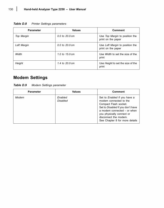
Hand-held Analyzer Type 2250 � User Manual130
Modem Settings
Top Margin 0.0 to 20.0 cm Use Top Margin to position the print on the paper
Left Margin 0.0 to 20.0 cm Use Left Margin to position the print on the paper
Width 1.0 to 15.0 cm Use Width to set the size of the print
Height 1.4 to 20.0 cm Use Height to set the size of the print
Table D.9 Modem Settings parameter
Parameter Values Comment
Modem EnabledDisabled
Set to Enabled if you have a modem connected to the Compact Flash socket.Set to Disabled if you don�t have a modem connected � or when you physically connect or disconnect the modem.See Chapter 8 for more details
Table D.8 Printer Settings parameters
Parameter Values Comment
131
Appendix EGlossary
A-weighting filter: Frequency weighting corresponding approximately to the 40 dB equal loudness curve, that is to say, the human ear�s response at low to medium sound levels. It is by far the most commonly applied frequency weighting. See also C-weighting and frequency weighting.
C-weighting filter: Frequency weighting corresponding to the 100 dB equal loudness curve, that is to say, the human ear�s response at fairly high sound levels. Mainly used when assessing peak values of high sound pressure levels. See also A-weighting and frequency weighting.
decibel (dB): The measurement unit for expressing the relative intensity of sound. A direct application of linear scales (in Pa) to the measurement of sound pressure leads to large and unwieldy numbers. As the ear responds logarithmically rather than linearly to stimuli, it is more practical to express acoustic parameters as a logarithmic ratio of the measured value to a reference value. This logarithmic ratio is called a decibel or dB. The advantage of using dB can be clearly seen in the below illustration. Here, the linear scale with its large numbers is converted into a manageable scale from 0 dB at the threshold of hearing (20μPa) to 130 dB at the threshold of pain (∼100 Pa).
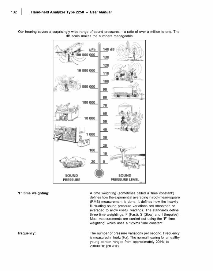
Hand-held Analyzer Type 2250 � User Manual132
Our hearing covers a surprisingly wide range of sound pressures � a ratio of over a million to one. The dB scale makes the numbers manageable
�F� time weighting: A time weighting (sometimes called a �time constant�) defines how the exponential averaging in root-mean-square (RMS) measurement is done. It defines how the heavily fluctuating sound pressure variations are smoothed or averaged to allow useful readings. The standards define three time weightings: F (Fast), S (Slow) and I (Impulse). Most measurements are carried out using the �F� time weighting, which uses a 125 ms time constant.
frequency: The number of pressure variations per second. Frequency is measured in hertz (Hz). The normal hearing for a healthy young person ranges from approximately 20 Hz to 20000 Hz (20 kHz).
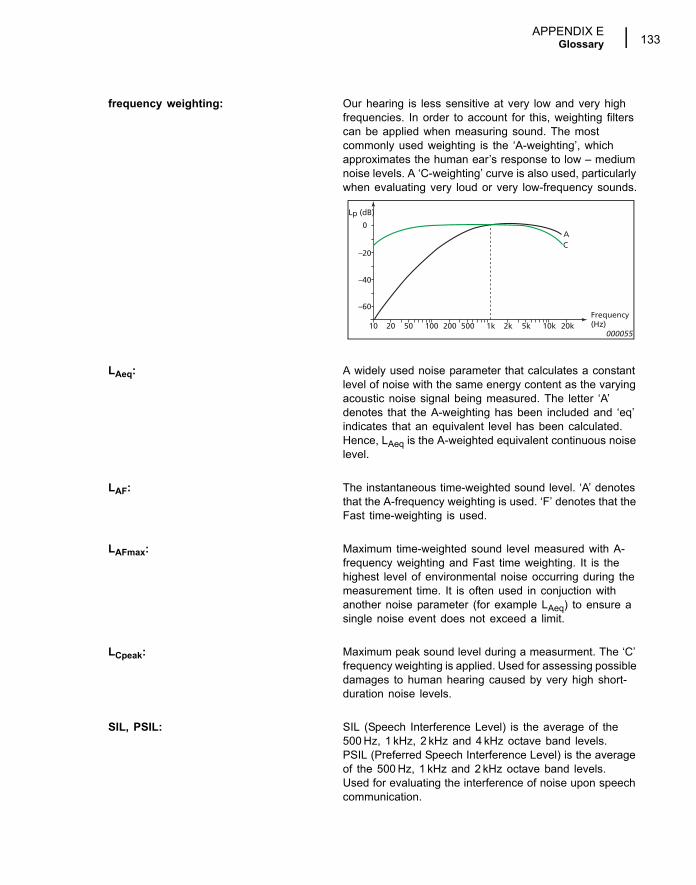
APPENDIX EGlossary 133
frequency weighting: Our hearing is less sensitive at very low and very high frequencies. In order to account for this, weighting filters can be applied when measuring sound. The most commonly used weighting is the �A-weighting�, which approximates the human ear�s response to low � medium noise levels. A �C-weighting� curve is also used, particularly when evaluating very loud or very low-frequency sounds.
LAeq: A widely used noise parameter that calculates a constant level of noise with the same energy content as the varying acoustic noise signal being measured. The letter �A� denotes that the A-weighting has been included and �eq� indicates that an equivalent level has been calculated. Hence, LAeq is the A-weighted equivalent continuous noise level.
LAF: The instantaneous time-weighted sound level. �A� denotes that the A-frequency weighting is used. �F� denotes that the Fast time-weighting is used.
LAFmax: Maximum time-weighted sound level measured with A-frequency weighting and Fast time weighting. It is the highest level of environmental noise occurring during the measurement time. It is often used in conjuction with another noise parameter (for example LAeq) to ensure a single noise event does not exceed a limit.
LCpeak: Maximum peak sound level during a measurment. The �C� frequency weighting is applied. Used for assessing possible damages to human hearing caused by very high short-duration noise levels.
SIL, PSIL: SIL (Speech Interference Level) is the average of the 500 Hz, 1 kHz, 2 kHz and 4 kHz octave band levels.PSIL (Preferred Speech Interference Level) is the average of the 500 Hz, 1 kHz and 2 kHz octave band levels.Used for evaluating the interference of noise upon speech communication.
000055
Frequency(Hz)
0
Lp (dB)
10 20 50 100 200 500 1k 2k 5k 10k 20k
–20
–40
–60
AC

Hand-held Analyzer Type 2250 � User Manual134
sound: Any pressure variation that the human ear can detect. Just like dominoes, a wave motion is set off when an element sets the nearest particle of air into motion. This motion gradually spreads to adjacent air particles further away from the source. Depending on the medium, sound extends and affects a greater area (propagates) at different speeds. In air, sound propagates at a speed of approximately 340 m/s. In liquids and solids, the propagation velocity is greater � 1500 m/s in water and 5000 m/s in steel.
Sound level or sound pressure level: The level in decibels of the pressure variation of a sound. See also decibel.
135
Index
Numerics1/1- or 1/3-octave Frequency Analysis .....................692250 Frequency Analysis Software BZ 7223..... 25, 692250 Logging Software BZ 7224 ....................... 25, 732250 Sound Recording Option BZ 7226...................252250 Sound Recording Software BZ 7226 ...............854189..........................................................................41
AAccept Pushbutton......................................................5Acoustic Calibration ..................................................37Adaptor for Standard Tripod .......................................6Adding Comments on Profiles ..................................82Adding Notes on Profiles ..........................................82Advanced use of Type 2250
Tips and Tricks ....................................................51Alhambra Colour Scheme.........................................52Alternative Measurement Method.............................11Annotating a Project .................................................76Annotating Sound Categories...................................82Annotations........................................................ 21, 47
Inserting Using Explorer ......................................47Viewing or Listening To .......................................46
ApplicationsHow to Update/Upgrade Them............................61
Arcade Colour Scheme.............................................52Assembling Type 2250 .............................................10Assembling your Type 2250 .......................................3Averaging Time.........................................................31A-weighting ...............................................................23A-weighting filter .....................................................131
BBack-erase Pushbutton ....................................... 5, 32Backlight Icon ...........................................................31Bandwidth Parameters ...........................................104Basic Principles when using Type 2250 ...................26Battery Charge Indicator...................................... 8, 63Battery Pack .............................................................63Battery Pack QB 0061 ..............................................10
Battery/power Status Icon ................................... 7, 31Broadband Frequency Weighting............................. 18Broadband View ....................................................... 17Built-in Help .............................................................. 25BZ 5503 Utility Software
for Hand-held Analyzers...................................... 25BZ 7222 Sound Level Meter Software ....................... 1
For Type 2250..................................................... 24BZ 7223 Frequency Analysis Software .........1, 25, 69BZ 7224 Logging Software............................1, 25, 73BZ 7226 Sound Recording Software................... 1, 85
CCalibration ................................................................ 37
Acoustic............................................................... 37Electrical.............................................................. 40History ................................................................. 40History Parameter ............................................. 123Screen................................................................. 29Settings ............................................................... 39Standard.............................................................. 37
Calibration Setup.................................................... 124Calibrator
Sound Level ........................................................ 37Care, Cleaning and Storage..................................... 67Central View Area .................................................... 31CF Cards .................................................................... 8Changing the Project Template................................ 15Character Keyboard ................................................. 35Charging the Battery for the First Time .................... 10Cleaning the Instrument ........................................... 67Clock Display............................................................ 32Cold Start ................................................................. 14Colour Schemes....................................................... 52Commentary............................................................. 47Commentary Icon ..................................................... 30Commentary Pushbutton..................................... 5, 20Comments ................................................................ 21
Adding on Profiles ............................................... 82
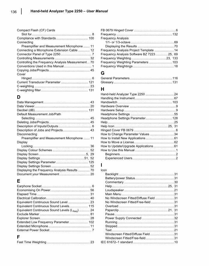
136 Hand-held Analyzer Type 2250 � User Manual
Compact Flash (CF) CardsSlot for ................................................................... 8
Compliance with Standards.................................... 100Connecting
Preamplifier and Measurement Microphone ....... 11Connecting a Microphone Extension Cable ............. 12Connector Panel of Type 2250................................... 7Controlling Measurements ....................................... 32Controlling the Frequency Analysis Measurement... 70Conventions Used in this Manual............................... 1Copying Jobs/Projects.............................................. 45Cover
Hinged................................................................... 6Current Transducer Parameter .............................. 121C-weighting .............................................................. 23C-weighting filter..................................................... 131
DData Management.................................................... 43Data Viewer.............................................................. 20Decibel (dB)............................................................ 131Default Measurement Job/Path
Selecting ............................................................. 45Deleting Jobs/Projects.............................................. 45Description of Inputs/Outputs ..................................... 6Description of Jobs and Projects.............................. 43Disconnecting
Preamplifier and Measurement Microphone ....... 11Display
Locking................................................................ 36Display Colour Schemes .......................................... 52Display Screen .....................................................5, 29Display Settings..................................................51, 52Display Settings Parameter.................................... 125Display Settings Screen ........................................... 52Displaying the Frequency Analysis Results ............. 70Document your Measurement .................................. 20
EEarphone Socket........................................................ 6Economising On Power............................................ 56Elapsed Time ........................................................... 31Electrical Calibration................................................. 40Equivalent Continuous Sound Level ........................ 23Equivalent Continuous Sound Levels..................... 115Equivalent Continuous Sound Levels (LAeq) ............ 24Exclude Marker ........................................................ 81Explorer Screen........................................................ 28Extended Low Frequency Parameter..................... 102Extended Microphone .............................................. 11External Power Socket ............................................... 7
FFast Time Weighting ................................................ 23
FB 0679 Hinged Cover ...............................................6Frequency ...............................................................132Frequency Analysis
1/1- or 1/3-octave.................................................69Displaying the Results .........................................70
Frequency Analysis Project Template ......................14Frequency Analysis Software BZ 7223..............25, 69Frequency Weighting .......................................23, 133Frequency Weighting Parameters ..........................103Frequency Weightings ..............................................18
GGeneral Parameters................................................116Glossary..................................................................131
HHand-held Analyzer Type 2250 ................................24Handling the Instrument............................................67Handswitch .............................................................103Hardware Overview ....................................................9Hardware Setup ..........................................................9Headphone Settings .................................................55Headphone Settings Parameter..............................128Help...........................................................................25Help Icon............................................................25, 31Hinged Cover FB 0679 ...............................................6How to Change Parameter Values ...........................34How to Install New Applications................................61How to Move a License.............................................62How to Update/Upgrade Applications .......................61How to Use this Manual ..............................................1
Beginners...............................................................2Experienced Users.................................................2
IIcon
Backlight ..............................................................31Battery/power Status............................................31Commentary ........................................................30Help...............................................................25, 31Loudspeaker ........................................................21Main Menu ...........................................................31No Windscreen Fitted/Diffuse Field .....................31No Windscreen Fitted/Free-field ..........................31Overload ..............................................................31Paperclip .......................................................21, 31Pause...................................................................31Power Supply Connected ....................................32Running................................................................31Stopped................................................................31Text ......................................................................21Windscreen Fitted/Diffuse Field ...........................31Windscreen Fitted/Free-field................................31
IEC 61672�1 standard ..............................................10
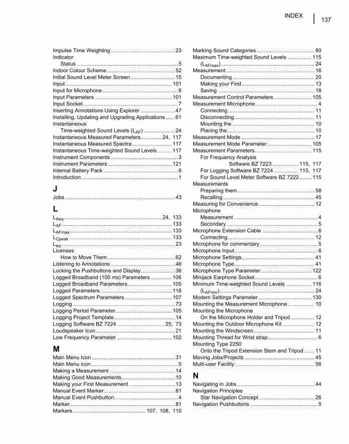
INDEX137
Impulse Time Weighting ...........................................23Indicator
Status ....................................................................5Indoor Colour Scheme..............................................52Initial Sound Level Meter Screen..............................15Input........................................................................101Input for Microphone...................................................6Input Parameters ....................................................101Input Socket................................................................7Inserting Annotations Using Explorer .......................47Installing, Updating and Upgrading Applications ......61Instantaneous
Time-weighted Sound Levels (LAF) .....................24Instantaneous Measured Parameters.............. 24, 117Instantaneous Measured Spectra...........................117Instantaneous Time-weighted Sound Levels..........117Instrument Components .............................................3Instrument Parameters ...........................................121Internal Battery Pack ..................................................6Introduction .................................................................1
JJobs ..........................................................................43
LLAeq.................................................................. 24, 133LAF ..........................................................................133LAFmax.....................................................................133LCpeak .....................................................................133Leq.............................................................................23Licenses
How to Move Them..............................................62Listening to Annotations ...........................................46Locking the Pushbuttons and Display.......................36Logged Broadband (100 ms) Parameters ..............106Logged Broadband Parameters..............................105Logged Parameters ................................................118Logged Spectrum Parameters................................107Logging .....................................................................73Logging Period Parameter......................................105Logging Project Template.........................................14Logging Software BZ 7224 ................................ 25, 73Loudspeaker Icon .....................................................21Low Frequency Parameter .....................................102
MMain Menu Icon ........................................................31Main Menu icon ..........................................................5Making a Measurement ............................................14Making Good Measurements....................................10Making your First Measurement ...............................13Manual Event Marker................................................81Manual Event Pushbutton...........................................4Marker.......................................................................81Markers................................................. 107, 108, 110
Marking Sound Categories....................................... 80Maximum Time-weighted Sound Levels ................ 115
(LAFmax)............................................................... 24Measurement ........................................................... 16
Documenting ....................................................... 20Making your First................................................. 13Saving ................................................................. 18
Measurement Control Parameters ......................... 105Measurement Microphone.......................................... 4
Connecting .......................................................... 11Disconnecting...................................................... 11Mounting the........................................................ 10Placing the........................................................... 10
Measurement Mode ................................................. 17Measurement Mode Parameter.............................. 105Measurement Parameters...................................... 115
For Frequency AnalysisSoftware BZ 7223 ................. 115, 117
For Logging Software BZ 7224 ................ 115, 117For Sound Level Meter Software BZ 7222........ 115
MeasurementsPreparing them.................................................... 58Recalling.............................................................. 45
Measuring for Convenience ..................................... 12Microphone
Measurement ........................................................ 4Secondary ............................................................. 5
Microphone Extension Cable ..................................... 6Connecting .......................................................... 12
Microphone for commentary....................................... 5Microphone Input........................................................ 6Microphone Settings................................................. 41Microphone Type...................................................... 41Microphone Type Parameter.................................. 122Minijack Earphone Socket.......................................... 6Minimum Time-weighted Sound Levels ................. 116
(LAFmin)................................................................ 24Modem Settings Parameter.................................... 130Mounting the Measurement Microphone.................. 10Mounting the Microphone
On the Microphone Holder and Tripod................ 12Mounting the Outdoor Microphone Kit...................... 12Mounting the Windscreen......................................... 11Mounting Thread for Wrist strap................................. 6Mounting Type 2250
Onto the Tripod Extension Stem and Tripod ....... 11Moving Jobs/Projects ............................................... 45Multi-user Facility ..................................................... 56
NNavigating in Jobs .................................................... 44Navigation Principles
Star Navigation Concept ..................................... 26Navigation Pushbuttons ............................................. 5
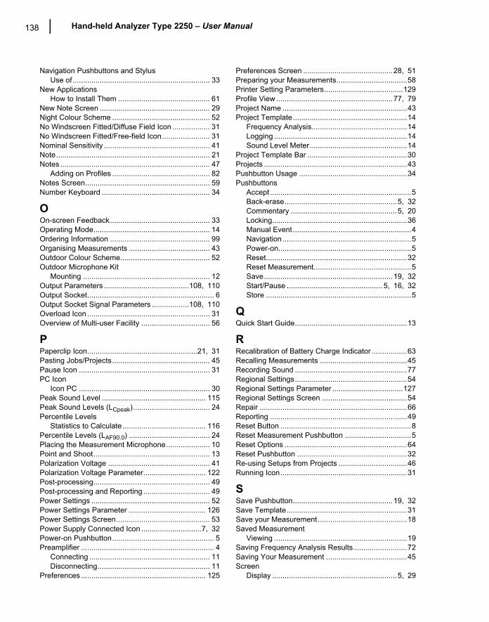
138 Hand-held Analyzer Type 2250 � User Manual
Navigation Pushbuttons and StylusUse of.................................................................. 33
New ApplicationsHow to Install Them ............................................ 61
New Note Screen ..................................................... 29Night Colour Scheme ............................................... 52No Windscreen Fitted/Diffuse Field Icon .................. 31No Windscreen Fitted/Free-field Icon....................... 31Nominal Sensitivity ................................................... 41Note.......................................................................... 21Notes ........................................................................ 47
Adding on Profiles ............................................... 82Notes Screen............................................................ 59Number Keyboard .................................................... 34
OOn-screen Feedback................................................ 33Operating Mode........................................................ 14Ordering Information ................................................ 99Organising Measurements ....................................... 43Outdoor Colour Scheme........................................... 52Outdoor Microphone Kit
Mounting ............................................................. 12Output Parameters .........................................108, 110Output Socket............................................................. 6Output Socket Signal Parameters ..................108, 110Overload Icon ........................................................... 31Overview of Multi-user Facility ................................. 56
PPaperclip Icon.....................................................21, 31Pasting Jobs/Projects............................................... 45Pause Icon ............................................................... 31PC Icon
Icon PC ............................................................... 30Peak Sound Level .................................................. 115Peak Sound Levels (LCpeak)..................................... 24Percentile Levels
Statistics to Calculate ........................................ 116Percentile Levels (LAF90.0) ....................................... 24Placing the Measurement Microphone..................... 10Point and Shoot........................................................ 13Polarization Voltage ................................................. 41Polarization Voltage Parameter.............................. 122Post-processing........................................................ 49Post-processing and Reporting ................................ 49Power Settings ......................................................... 52Power Settings Parameter ..................................... 126Power Settings Screen............................................. 53Power Supply Connected Icon .............................7, 32Power-on Pushbutton................................................. 5Preamplifier ................................................................ 4
Connecting .......................................................... 11Disconnecting...................................................... 11
Preferences ............................................................ 125
Preferences Screen ...........................................28, 51Preparing your Measurements..................................58Printer Setting Parameters......................................129Profile View ........................................................77, 79Project Name ............................................................43Project Template.......................................................14
Frequency Analysis..............................................14Logging ................................................................14Sound Level Meter...............................................14
Project Template Bar ................................................30Projects .....................................................................43Pushbutton Usage ....................................................34Pushbuttons
Accept ....................................................................5Back-erase......................................................5, 32Commentary ...................................................5, 20Locking.................................................................36Manual Event .........................................................4Navigation..............................................................5Power-on................................................................5Reset....................................................................32Reset Measurement...............................................5Save..............................................................19, 32Start/Pause .............................................. 5, 16, 32Store ......................................................................5
QQuick Start Guide......................................................13
RRecalibration of Battery Charge Indicator .................63Recalling Measurements ..........................................45Recording Sound ......................................................77Regional Settings......................................................54Regional Settings Parameter ..................................127Regional Settings Screen .........................................54Repair .......................................................................66Reporting ..................................................................49Reset Button ...............................................................8Reset Measurement Pushbutton ................................5Reset Options ...........................................................64Reset Pushbutton .....................................................32Re-using Setups from Projects .................................46Running Icon.............................................................31
SSave Pushbutton................................................19, 32Save Template..........................................................31Save your Measurement...........................................18Saved Measurement
Viewing ................................................................19Saving Frequency Analysis Results..........................72Saving Your Measurement .......................................45Screen
Display ............................................................5, 29
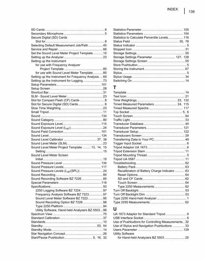
INDEX139
SD Cards ....................................................................8Secondary Microphone...............................................5Secure Digital (SD) Cards
Slot for ...................................................................8Selecting Default Measurement Job/Path ................45Service and Repair ...................................................66Set the Sound Level Meter Project Template ...........15Setting up the Analyzer.............................................23Setting up the Instrument
for use with Frequency AnalyzerProject Template ............................................85
for use with Sound Level Meter Template ...........85Setting up the Instrument for Frequency Analysis ....69Setting up the Instrument for Logging.......................73Setup Parameters...................................................101Setup Screen ............................................................28Shortcut Bar..............................................................31SLM - Sound Level Meter .........................................23Slot for Compact Flash (CF) Cards ............................8Slot for Secure Digital (SD) Cards ..............................8Slow Time Weighting ................................................23Small Tripod..............................................................11Sound .....................................................................134Sound Category........................................................80Sound Exposure Level............................................115Sound Exposure Level (LAF).....................................24Sound Field Correction ...........................................101Sound Level............................................................134Sound Level Calibrator ...................................... 37, 38Sound Level Meter (SLM).........................................23Sound Level Meter Project Template ......... 13, 14, 15
Setting .................................................................15Sound Level Meter Screen
Initial ....................................................................15Sound Pressure Level ............................................134Sound Pressure Levels...........................................117Sound Pressure Levels (LAF(SPL)) ..........................24Sound Recording ......................................................85Sound Recording Software BZ 7226 ........................85Special Parameters ................................................116Specifications............................................................93
2250 Logging Software BZ 7224 .........................97Frequency Analysis Software BZ 7223................97Sound Level Meter Software BZ 7222.................95Sound Recording Option BZ 7226.......................98Type 2250 Platform .............................................94Utility Software, Hand-held Analyzers BZ 5503...98
Spectrum View..........................................................70Standard Calibration .................................................37Standards .................................................................10Standby.............................................................. 53, 54Standby Mode...........................................................14Star Navigation Concept...........................................26Start/Pause Pushbutton................................ 5, 16, 32
Statistics Parameter ............................................... 105Statistics Parameters ............................................. 104Statistics to Calculate Percentile Levels................. 116Status Field ....................................................... 30, 78Status Indicator .......................................................... 5Stopped Icon ............................................................ 31Storage Settings....................................................... 55Storage Settings Parameter .......................... 127, 128Storage Settings Screen .......................................... 55Store Pushbutton........................................................ 5Storing the Instrument .............................................. 67Stylus.......................................................................... 5Stylus Usage ............................................................ 34Switching On ............................................................ 14
TTemplate .................................................................. 14Text Icon................................................................... 21Time Weightings.............................................. 23, 132Timed Measured Parameters.......................... 24, 115Timed Measured Spectra ....................................... 117Top Socket ............................................................ 5, 6Touch Screen ........................................................... 64Traffic Light............................................................... 33Transducer Database............................................... 40Transducer Parameters.......................................... 121Transducer Setup................................................... 122Transducers Screen ................................................. 29Transferring Data to Your PC................................... 49Trigger Input Socket ................................................... 6Tripod Adaptor UA 1673............................................. 6Tripod Extension Stem ............................................. 11Tripod Mounting Thread ............................................. 5Tripod UA 0587 ........................................................ 11Troubleshooting........................................................ 62
Battery Pack........................................................ 63Recalibration of Battery Charge Indicator ........... 63Reset Options...................................................... 64SD and CF Cards ................................................ 62Touch Screen...................................................... 64Type 2250 Measurements................................... 62
Turn Off Backlight..................................................... 53Turn Off Backlight Dim ............................................. 53Type 2250 Hand-held Analyzer.................................. 1Type 2250 Measurements........................................ 62
UUA 1673 Adaptor for Standard Tripod........................ 6USB Interface Socket ................................................. 6Use of Pushbuttons for Controlling Measurements.. 32Use of Stylus and Navigation Pushbuttons .............. 33Users Parameter .................................................... 129Utility Software
for Hand-held Analyzers BZ 5503 ....................... 25
140 Hand-held Analyzer Type 2250 � User Manual
VViewer ...................................................................... 45Viewing Data ............................................................ 45Viewing or Listening to Annotations ......................... 46Viewing the Saved Measurement............................. 19
WWarm Start ............................................................... 14Welcome ................................................................1, 3What is a Project Template? .................................... 14What is a Sound Level Meter? ................................. 23What is a Type 2250 Hand-held Analyzer?.............. 24
What is Utility Softwarefor Hand-held Analyzers BZ 5503?......................25
WindscreenMounting ..............................................................11
Windscreen Correction Parameter..........................102Windscreen Fitted/Diffuse Field Icon ........................31Windscreen Fitted/Free-field Icon .............................31Wrist Strap Mounting Thread ......................................6
XXL View.....................................................................17
ZZ-weighting ...............................................................23

TechnicalDocumentation
HEADQUARTERS: DK-2850 Nærum · Denmark · Telephone: +45 4580 0500 · Fax: +45 4580 1405 · www.bksv.com · [email protected]
Australia (+61) 2 9889-8888 · Austria (+43) 1 865 74 00 · Brazil (+55)11 5188-8166 · Canada (+1) 514 695-8225China (+86) 10 680 29906 · Czech Republic (+420) 2 6702 1100 · Finland (+358) 9-521 300 · France (+33) 1 69 90 71 00Germany (+49) 421 17 87 0 · Hong Kong (+852) 2548 7486 · Hungary (+36) 1 215 83 05 · Ireland (+353) 1 807 4083Italy (+39) 0257 68061 · Japan (+81) 3 5715 1612 · Korea (+82) 2 3473 0605 · Netherlands (+31)318 55 9290 · Norway (+47) 66 77 11 55Poland (+48) 22 816 75 56 · Portugal (+351) 21 47 11 4 53 · Singapore (+65) 377 4512 · Slovak Republic (+421) 25 443 0701Spain (+34) 91 659 0820 · Sweden (+46) 8 449 8600 · Switzerland (+41) 44 880 7035 · Taiwan (+886) 2 2502 7255United Kingdom (+44) 14 38 739 000 · USA (+1) 800 332 2040
Local representatives and service organisations worldwide
Hand-held Analyzer Type 2250
With 2250 Sound Level Meter Software BZ 7222,2250 Frequency Analysis Software BZ 7223 and2250 Logging Software BZ 7224 and2250 Sound Recording Option BZ 7226
English BE 1713 – 15
User Manual
ËBE-1713---|Î
BE1713-15_Cover.fm Page 1 Tuesday, August 30, 2005 2:40 PM