Embed Size (px)
Citation preview

Technical Evaluation Report TER 1609-08
SFS Group USA, Inc. ConnexTite™ Fasteners
SFS Group USA, Inc.
Product:
SFS Group USA, Inc. ConnexTite™ Fasteners
Issue Date:
July 10, 2017 Revision Date:
November 4, 2021 Subject to Renewal:
October 1, 2022

TER 1609-08
SFS GROUP USA, INC. CONNEXTITE™ FASTENERS © 2021 DRJ ENGINEERING, LLC
SUBJECT TO RENEWAL 10/1/2022 PAGE 2 OF 16
COMPANY INFORMATION:
SFS Group USA, Inc.
1045 Spring St Wyomissing, PA 19610-1747
Phone: 610-376-5751
us.sfs.com
DIVISION: 06 00 00 - WOOD, PLASTICS AND COMPOSITES
SECTION: 06 05 23 - Wood, Plastic, and Composite Fastenings
1 PRODUCT EVALUATED1 1.1 SFS Group USA, Inc. ConnexTite™ Fasteners
2 APPLICABLE CODES AND STANDARDS2,3 2.1 Codes
2.1.1 IBC—15, 18, 21: International Building Code® 2.1.2 IRC—15, 18, 21: International Residential Code®
2.2 Standards and Referenced Documents 2.2.1 AISI S904: Standard Test Methods for Determining the Tensile and Shear Strength of Screws 2.2.2 ANSI/AWC NDS: National Design Specification (NDS) for Wood Construction 2.2.3 ASTM A153: Standard Specification for Zinc Coating (Hot-Dip) on Iron and Steel Hardware 2.2.4 ASTM A510: Standard Specification for General Requirements for Wire Rods and Coarse Round Wire,
Carbon Steel, and Alloy Steel 2.2.5 ASTM D1761: Standard Test Methods for Mechanical Fasteners in Wood and Wood-Based Materials 2.2.6 ASTM F1575: Standard Test Method for Determining Bending Yield Moment of Nails 2.2.7 ASTM F1941: Standard Specification for Electrodeposited Coatings on Mechanical Fasteners
3 PERFORMANCE EVALUATION 3.1 SFS Group USA, Inc. ConnexTite™ carbon steel fasteners were tested and evaluated to determine their
structural resistance properties, which are used to develop reference design values for allowable stress design (ASD). The following conditions were evaluated:
3.1.1 Withdrawal strength in accordance with ASTM D1761 3.1.2 Bending yield in accordance with ASTM F1575
1 For more information, visit drjcertification.org or call us at 608-310-6748. 2 Unless otherwise noted, all references in this TER are from the 2021 version of the codes and the standards referenced therein. This material, design, or method of construction also complies with the 2000-2018 versions of the referenced codes and the standards referenced therein. 3 All terms defined in the applicable building codes are italicized.

TER 1609-08
SFS GROUP USA, INC. CONNEXTITE™ FASTENERS © 2021 DRJ ENGINEERING, LLC
SUBJECT TO RENEWAL 10/1/2022 PAGE 3 OF 16
3.1.3 Tensile strength in accordance with AISI S904 3.1.4 Head pull-through in accordance with NDS 3.1.5 Lateral resistance in accordance with ASTM D1761
3.2 Any code compliance issues not specifically addressed in this section are outside the scope of this TER. 3.3 Any engineering evaluation conducted for this TER was performed within DrJ’s ANAB “accredited ICS code
scope” and/or the defined professional engineering scope of work on the dates provided herein.
4 PRODUCT DESCRIPTION AND MATERIALS 4.1 The product evaluated in this TER is shown in Figure 1, Figure 2, Figure 3, and Figure 4.
FIGURE 1. SFS GROUP USA, INC. CONNEXTITE™ FLANGE HEAD DETAIL
FIGURE 2. SFS GROUP USA, INC. CONNEXTITE™ FLANGE HEAD FULLY THREADED AND PARTIALLY THREADED FASTENER DETAILS
FIGURE 3. SFS GROUP USA, INC. CONNEXTITE™ COUNTERSINK HEAD DETAIL
FIGURE 4. SFS GROUP USA, INC. CONNEXTITE™ COUNTERSINK HEAD FULLY THREADED AND PARTIALLY THREADED FASTENER DETAILS
TER 1609-08
SFS GROUP USA, INC. CONNEXTITE™ FASTENERS © 2021 DRJ ENGINEERING, LLC
SUBJECT TO RENEWAL 10/1/2022 PAGE 4 OF 16
4.2 SFS Group USA, Inc. ConnexTite™ fasteners are made of cold-formed, heat-treated, carbon steel. 4.3 Fasteners are available in lengths up to 19¾″ inches. 4.4 Fasteners may be treated with either a proprietary corrosion resistant coating or a zinc plating. 4.5 Corrosion Resistant Fasteners
4.5.1 Fasteners are designed for exterior use and may be used where fasteners are required to exhibit corrosion resistance when exposed to adverse environmental conditions and/or in preservative treated wood subject to the limitations of Section 9.
4.5.2 Fasteners are coated with a proprietary coating system that meets or exceeds the corrosion protection of hot-dipped galvanizing per ASTM A153 in accordance with IBC Section 2304.10 and IRC Section R317.3.
4.5.3 Fasteners are alternatives to hot-dip-zinc galvanized fasteners. 4.5.4 Fasteners are approved for use in fire-retardant-treated lumber, provided the conditions set forth by the
fire-retardant-treated lumber manufacturer are met, including appropriate strength reductions. 4.6 Zinc-plated Fasteners
4.6.1 Fasteners are zinc-plated per ASTM F1941. 4.6.2 Zinc-plated fasteners are approved for interior, dry use only.
4.7 The fasteners evaluated in this TER are set forth in Table 1. For additional fastener sizes, refer to Appendix A. TABLE 1. FASTENER SPECIFICATIONS
Fastener Name
Nominal Fastener Diameter
(in)
Head (in) Shank Diameter1
(in)
Thread Diameter (in)
Nominal Bending Yield, fyb, (psi)
Allowable Fastener Strength
(lbs)
Diameter Height Minor2 Major Transition Zone Shank Tensile Shear
ConnexTite™ Flange Head
1/4 0.552 0.094 0.173 0.148 0.244 201,611 237,010 970 485 5/16 0.709 0.148 0.228 0.207 0.315 167,894 178,866 1810 905 3/8 0.877 0.161 0.279 0.253 0.393 156,064 203,056 2545 1275
ConnexTite™ Countersink
Head
1/4 0.457 - 0.173 0.148 0.244 201,611 237,010 970 485 5/16 0.583 - 0.228 0.207 0.315 167,894 178,866 1810 905 3/8 0.728 - 0.279 0.253 0.393 156,064 203,056 2545 1275
SI: 1 in = 25.4 mm, 1 lb = 4.45 N 1. Shank diameter based on manufactured thickness. Finished dimensions are larger in the plated condition due to the proprietary coatings added. 2. Minor thread diameter value is calculated as the average of the upper and lower tolerances.
5 APPLICATIONS 5.1 General
5.1.1 SFS Group USA, Inc. ConnexTite™ fasteners are self-tapping fasteners used for connections in conventional light-frame construction and provide resistance against withdrawal, axial, and shear loads. See Section 6 for installation requirements.
5.1.2 SFS Group USA, Inc. ConnexTite™ fasteners can be used in applications including timber construction work (staircase construction and interior finishing), structural and general timber construction work and on-rafter insulation and façade attachment.
5.1.3 SFS Group USA, Inc. ConnexTite™ fasteners are installed without lead holes, as prescribed in NDS. 5.1.4 Where the application exceeds the limitations set forth herein, design shall be permitted in accordance with
accepted engineering procedures, experience, and good technical judgment.
TER 1609-08
SFS GROUP USA, INC. CONNEXTITE™ FASTENERS © 2021 DRJ ENGINEERING, LLC
SUBJECT TO RENEWAL 10/1/2022 PAGE 5 OF 16
5.2 Design 5.2.1 Design of SFS Group USA, Inc. ConnexTite™ fasteners is governed by the applicable code and the
provisions for dowel-type fasteners in NDS. 5.2.2 Unless otherwise noted, adjustment of the design stresses for duration of load shall be in accordance with the
applicable code. 5.3 SFS Group USA, Inc. ConnexTite™ Fastener Reference Withdrawal Design Values
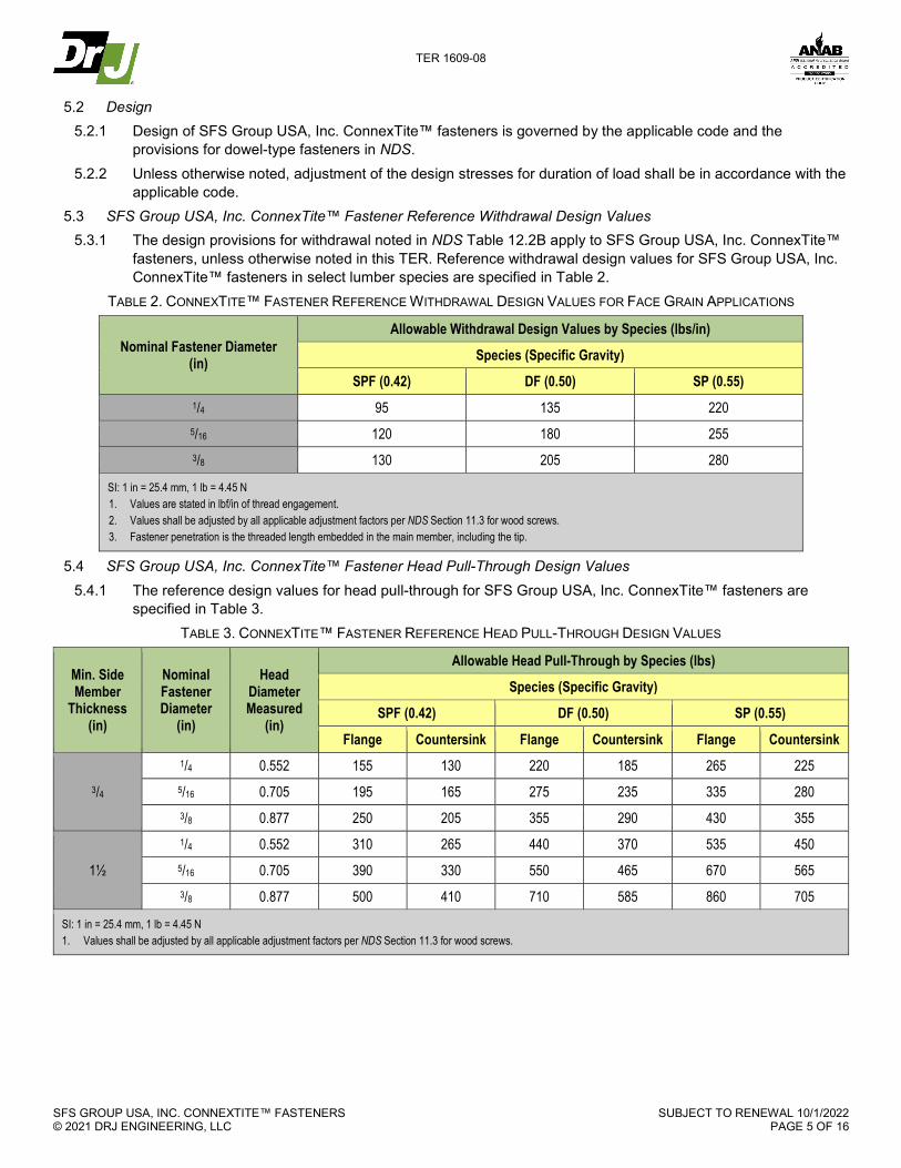
5.3.1 The design provisions for withdrawal noted in NDS Table 12.2B apply to SFS Group USA, Inc. ConnexTite™ fasteners, unless otherwise noted in this TER. Reference withdrawal design values for SFS Group USA, Inc. ConnexTite™ fasteners in select lumber species are specified in Table 2.
TABLE 2. CONNEXTITE™ FASTENER REFERENCE WITHDRAWAL DESIGN VALUES FOR FACE GRAIN APPLICATIONS
Nominal Fastener Diameter (in)
Allowable Withdrawal Design Values by Species (lbs/in)
Species (Specific Gravity)
SPF (0.42) DF (0.50) SP (0.55) 1/4 95 135 220 5/16 120 180 255 3/8 130 205 280
SI: 1 in = 25.4 mm, 1 lb = 4.45 N 1. Values are stated in lbf/in of thread engagement. 2. Values shall be adjusted by all applicable adjustment factors per NDS Section 11.3 for wood screws. 3. Fastener penetration is the threaded length embedded in the main member, including the tip.
5.4 SFS Group USA, Inc. ConnexTite™ Fastener Head Pull-Through Design Values 5.4.1 The reference design values for head pull-through for SFS Group USA, Inc. ConnexTite™ fasteners are
specified in Table 3. TABLE 3. CONNEXTITE™ FASTENER REFERENCE HEAD PULL-THROUGH DESIGN VALUES
Min. Side Member
Thickness (in)
Nominal Fastener Diameter
(in)
Head Diameter Measured
(in)
Allowable Head Pull-Through by Species (lbs)
Species (Specific Gravity)
SPF (0.42) DF (0.50) SP (0.55)
Flange Countersink Flange Countersink Flange Countersink
3/4
1/4 0.552 155 130 220 185 265 225 5/16 0.705 195 165 275 235 335 280 3/8 0.877 250 205 355 290 430 355
1½
1/4 0.552 310 265 440 370 535 450 5/16 0.705 390 330 550 465 670 565 3/8 0.877 500 410 710 585 860 705
SI: 1 in = 25.4 mm, 1 lb = 4.45 N 1. Values shall be adjusted by all applicable adjustment factors per NDS Section 11.3 for wood screws.

TER 1609-08
SFS GROUP USA, INC. CONNEXTITE™ FASTENERS © 2021 DRJ ENGINEERING, LLC
SUBJECT TO RENEWAL 10/1/2022 PAGE 6 OF 16
5.5 SFS Group USA, Inc. ConnexTite™ Fastener Reference Lateral Design Values – Face Grain Applications 5.5.1 The reference lateral design values for shear load perpendicular and parallel to grain for SFS Group USA,
Inc. ConnexTite™ fasteners are specified in Table 4 and Table 5. TABLE 4. CONNEXTITE™ FASTENER REFERENCE LATERAL DESIGN VALUES USING DIMENSIONAL LUMBER
Fastener Head Type
Nominal Fastener Diameter
(in)
Fastener Length
(in)
Side Member
Thickness (in)
Min. Penetration
into Main Member
(in)
Lateral Design Values (lbs)
Species (Specific Gravity)
SPF (0.42) DF (0.50) SP (0.55)
Z Para Z Perp Z Para Z Perp Z Para Z Perp
Flange
1/4
23/8
11/2
7/8 115 90 140 110 160 125
2¾ 1¼ 130 105 165 135 190 155
31/8 11/2
145 115 175 140 190 155 4 21/2
≥4¾ 3¼
5/16
2¾ 1¼ 155 125 215 170
525 550
31/8 15/8 175 140
245 195 4 2½
195 155 4¾ 3¼
≥5½ 4
3/8
31/8 1 5/8 180 145 250
200
300 240
4 2½
220 175 280 315 255 4¾" 3¼
≥5½ 4
Countersink
1/4
23/8 7/8 115 90 140 110 160 125
2¾ 1¼ 130 105 165 135
190 155 31/8 15/8
145 115 175 140 3½ 2
≥4 2½
5/16
31/8 15/8 175 140
245 195 285 225 3½ 2 195 155
≥4 2½
3/8
31/8 15/8 180 145 250 200 300 240
4 2½ 220 175 280 220 315 255
≥4¾ 3¼
SI: 1 in = 25.4 mm, 1 lb = 4.45 N 1. Reference lateral design values apply to two-member single shear connections where both members are of the same specific gravity, and the fastener is oriented perpendicular
to grain. Where the members are of different specific gravities, use the lower of the two. 2. Values shall be adjusted by all applicable adjustment factors per NDS.

TER 1609-08
SFS GROUP USA, INC. CONNEXTITE™ FASTENERS © 2021 DRJ ENGINEERING, LLC
SUBJECT TO RENEWAL 10/1/2022 PAGE 7 OF 16
TABLE 5. CONNEXTITE™ FASTENER REFERENCE LATERAL DESIGN VALUES USING ENGINEERED LUMBER
Fastener Head Type
Nominal Fastener Diameter
(in)
Fastener Length
(in)
Side Member Thickness
(in)
Min. Penetration into Main Member
(in)
Lateral Design Values (lbs)
Species (Specific Gravity)
LVL or LSL (0.50)
Z Para Z Perp
Flange
1/4
2
1¼
¾ 135 105
23/8 11/8 155 125
2¾ 1½ 165 135
2¾ 1½
1¼ 165 135
4 2½ 175 140
31/8 1¾ 13/8 175 140
5/16
2¾ 1¼ 1½ 215 170
2¾
1½
1¼ 215 170
4 2½ 245 195
5½ 4 245 195
31/8 1¾
13/8 235 190
4¾ 3 270 215
3/8
4 1½
2½ 280 220
5½ 4 280 220
4¾ 1¾ 3 300 240
Countersink
1/4
23/8 1¼
11/8 155 125
2¾ 1½ 165 135
2¾
1½
1¼ 165 135
3½ 2 175 140
43/8 27/8 175 140
57/8 43/8 175 140
31/8 1¾
13/8 175 140
3½ 1¾ 175 140
5/16
31/8 1¼ 17/8 225 180
4 1½
2½ 245 195
5½ 4 245 195
31/8
1¾
13/8 235 190
3½ 1¾ 270 215
4¾ 3 270 215
3/8
31/8 1¼ 17/8 260 205
4 1½
2½ 280 220
5½ 4 280 220
3½ 1¾ 1¾ 280 225

TER 1609-08
SFS GROUP USA, INC. CONNEXTITE™ FASTENERS © 2021 DRJ ENGINEERING, LLC
SUBJECT TO RENEWAL 10/1/2022 PAGE 8 OF 16
Fastener Head Type
Nominal Fastener Diameter
(in)
Fastener Length
(in)
Side Member Thickness
(in)
Min. Penetration into Main Member
(in)
Lateral Design Values (lbs)
Species (Specific Gravity)
LVL or LSL (0.50)
Z Para Z Perp
4¾ 3 300 240
SI: 1 in = 25.4 mm, 1 lb = 4.45 N 1. Reference lateral design values apply to two-member single shear connections where both members are of the same specific gravity, and the fastener is oriented perpendicular
to grain. Where the members are of different specific gravities, use the lower of the two. 2. Values shall be adjusted by all applicable adjustment factors per NDS.
5.6 SFS Group USA, Inc. ConnexTite™ Fastener Reference Lateral Design Values – Metal Side Plate 5.6.1 The reference lateral design values for shear load perpendicular and parallel to grain with a metal side plate
for SFS Group USA, Inc. ConnexTite™ fasteners are specified in Table 6. TABLE 6. CONNEXTITE™ FASTENER REFERENCE LATERAL DESIGN VALUES USING DIMENSIONAL LUMBER & METAL SIDE PLATE
Side Member (Metal Plate) Thickness (in)
Nominal Fastener2 Diameter (in)
Lateral Design Values1,3 (lbs)
Species (Specific Graviy)
DF (0.50)
Zpara Zperp
0.105 (12 gage)
5/16 565 595
0.134 (10 gage)
0.179 (7 gage)
0.239 (3 gage)
0.25
SI: 1 in = 25.4 mm, 1 lb = 4.45 N 1. Reference lateral design values apply to two-member single shear connections, where the main member is wood with a specific gravity greater than or equal to 0.50, the side
member is a metal side plate (ASTM A36), and the fastener is oriented perpendicular to grain. 2. Minimum fastener length is 2¾". 3. Values shall be adjusted by all applicable factors per NDS.

TER 1609-08
SFS GROUP USA, INC. CONNEXTITE™ FASTENERS © 2021 DRJ ENGINEERING, LLC
SUBJECT TO RENEWAL 10/1/2022 PAGE 9 OF 16
5.7 SFS Group USA, Inc. ConnexTite™ Fastener Spacing Requirements 5.7.1 Minimum fastener spacing requirements for SFS Group USA, Inc. ConnexTite™ fasteners are as follows in
Table 7. TABLE 7. CONNEXTITE™ MINIMUM FASTENER SPACING REQUIREMENTS
Nominal Fastener Diameter
(in)
Shank Diameter
(in)
Minimum Edge Distance (in) Minimum End Distance (in) Minimum On-Center Spacing (in)
Load Parallel to Grain
Load Perp. to
Grain
Between Fasteners in a Row Load Perp.
to Grain
Between Fasteners in a Row Between Rows
Load Toward
Fastener
Load Away From
Fastener Parallel to
Grain Perp. to
Grain Parallel to Grain
Perp. to Grain
¼ 0.173 3/8 1 1 1¾ 1 1 NDS Table
12.5.1D
3/8 1¼ 5/16 0.228 ½ 1¼ 1¼ 2¼ 1¼ 1¼ ½ 15/8 3/8 0.279 5/8 1½ 1½ 23/4 1½ 1½ 5/8 2
SI: 1 in = 25.4 mm, 1 lb = 4.45 N 1. Fastener spacing follows requirements of NDS Section 12.5. 2. Heavy or medium concentrated loads shall not be suspended below the neutral axis of a single sawn lumber or structural glued laminated timber beam except where mechanical or
equivalent reinforcement is provided to resist tension stresses perpendicular to grain. 3. Always space fasteners to avoid splitting of wood.
6 INSTALLATION 6.1 SFS Group USA, Inc. ConnexTite™ fasteners shall be installed in accordance with the applicable code, the
approved construction documents, this TER, the manufacturer’s installation instructions, NDS, and standard framing practice as applied to wood fasteners.
6.2 In the event of a conflict between the manufacturer’s installation instructions and this TER, the more restrictive shall govern.
6.3 Installation Procedure 6.3.1 Installed using Torx® bit by turning. Pre-drilling of pilot holes is not required but may be used where lumber is
prone to splitting. 6.3.2 Minimum penetration is 1ʺ unless otherwise stated in this TER.
7 SUBSTANTIATING DATA 7.1 Testing has been performed under the supervision of a professional engineer and/or under the requirements of
ISO/IEC 17025 as follows: 7.1.1 Withdrawal testing in accordance with ASTM D1761 7.1.2 Bending yield testing in accordance with ASTM F1575 7.1.3 Tensile strength testing in accordance with AISI S904 7.1.4 Lateral strength testing in accordance with ASTM D1761
7.2 ANSI/AWC NDS: National Design Specification (NDS) for Wood Construction 7.3 Information contained herein is the result of testing and/or data analysis by sources which conform to IBC Section
1703 and/or professional engineering regulations. DrJ relies upon accurate data to perform its ISO/IEC 17065 evaluations.

TER 1609-08
SFS GROUP USA, INC. CONNEXTITE™ FASTENERS © 2021 DRJ ENGINEERING, LLC
SUBJECT TO RENEWAL 10/1/2022 PAGE 10 OF 16
7.4 Where appropriate, DrJ’s analysis is based on provisions that have been codified into law through state or local adoption of codes and standards. The providers of the codes and standards are legally responsible for their content. DrJ analysis may use code-adopted provisions as a control sample. A control sample versus a test sample establishes a product as being equivalent to that prescribed in this code in quality, strength, effectiveness, fire resistance, durability, and safety. Where the accuracy of the provisions provided herein is reliant upon the published properties of materials, DrJ relies upon the grade mark, grade stamp, mill certificate, and/or test data provided by material suppliers to be minimum properties. DrJ analysis relies upon these properties to be accurate.
8 FINDINGS 8.1 When used and installed in accordance with this TER, the provisions of the applicable building codes, and the
manufacturer’s installation instructions, the product(s) listed in Section 1.1 are approved for the following: 8.1.1 Use as an alternative to those fasteners prescribed by the applicable code using the reference design value
properties defined herein. 8.2 This product has been evaluated in the context of the codes listed in Section 2 and is compliant with all known
state and local building codes. Where there are known variations in state or local codes applicable to this TER, they are listed here.
8.2.1 No known variations 8.3 Building codes require data from valid research reports be obtained from approved sources (i.e., licensed
registered design professionals [RDPs]). 8.3.1 Building official approval of a licensed RDP is performed by verifying the RDP and/or their business entity is
listed by the licensing board of the relevant jurisdiction. 8.4 Agencies who are accredited through ISO/IEC 17065 have met the code requirements for approval by the
building official. DrJ is an ISO/IEC 17065 ANAB-Accredited Product Certification Body – Accreditation #1131 and employs RDPs.
8.5 Through ANAB accreditation and the IAF MLA, DrJ certification can be used to obtain product approval in any jurisdiction or country that has IAF MLA Members & Signatories to meet the Purpose of the MLA – “certified once, accepted everywhere.”
8.6 IBC Section 104.11 (IRC Section R104.11 and IFC Section 104.104 are similar) states:
104.11 Alternative materials, design and methods of construction and equipment. The provisions of this code are not intended to prevent the installation of any material or to prohibit any design or method of construction not specifically prescribed by this code…Where the alternative material, design or method of construction is not approved, the building official shall respond in writing, stating the reasons the alternative was not approved.
9 CONDITIONS OF USE 9.1 Zinc-plated fasteners are approved for interior, dry use only. 9.2 Where required by the building official, also known as the authority having jurisdiction (AHJ) in which the project is
to be constructed, this TER and the installation instructions shall be submitted at the time of permit application. 9.3 Any generally accepted engineering calculations needed to show compliance with this TER shall be submitted to
the AHJ for review and approval. 9.4 Design loads shall be determined in accordance with the building code adopted by the jurisdiction in which the
project is to be constructed and/or by the building designer (e.g., owner or RDP). 9.5 At a minimum, this product shall be installed per Section 6 of this TER. 9.6 This product has an internal quality control program and a third-party quality assurance program in accordance
with IBC Section 104.4 and Section 110.4 and IRC Section R104.4 and Section R109.2.
4 2018 IFC Section 104.9

TER 1609-08
SFS GROUP USA, INC. CONNEXTITE™ FASTENERS © 2021 DRJ ENGINEERING, LLC
SUBJECT TO RENEWAL 10/1/2022 PAGE 11 OF 16
9.7 The actual design, suitability, and use of this TER, for any particular building, is the responsibility of the owner or the owner's authorized agent.
9.8 This TER shall be reviewed for code compliance by the AHJ in concert with IBC Section 104. 9.9 The implementation of this TER for this product is dependent on the design, quality control, third-party quality
assurance, proper implementation of installation instructions, inspections required by IBC Section 110.3, and any other code or regulatory requirements that may apply.
10 IDENTIFICATION 10.1 The product(s) listed in Section 1.1 are identified by a label on the board or packaging material bearing the
manufacturer’s name, product name, TER number, and other information to confirm code compliance. Individual fasteners are marked with a stylized head stamp and fastener diameter as shown in Figure 1 and Figure 3.
10.2 Additional technical information can be found at us.sfs.com.
11 REVIEW SCHEDULE 11.1 This TER is subject to periodic review and revision. For the most recent version, visit drjcertification.org. 11.2 For information on the current status of this TER, contact DrJ Certification.

TER 1609-08
SFS GROUP USA, INC. CONNEXTITE™ FASTENERS © 2021 DRJ ENGINEERING, LLC
SUBJECT TO RENEWAL 10/1/2022 PAGE 12 OF 16
APPENDIX A TABLE 8. SFS GROUP USA, INC. CONNEXTITE™ FLANGE HEAD
Fastener Name
Nominal Diameter
Head Fastener Length
(in)
Thread Length
(in)
Shank Diameter
(in)
Thread Diameter (in)
Diameter (in) Thickness (in) Minor Major
SFS Group USA, Inc. ConnexTite™
Flange Head
1/4 0.552 0.094
1-1/2 1-1/4
0.173 0.155 0.244
2 1-5/8
2-3/8 2
2-3/4 2-3/8
3-1/8
2-3/4
4
4-3/4
5-1/2
6-1/4
7-1/8
7-7/8
8-5/8
9-3/8
10-1/4
11
11-3/4
5/16 0.705 0.148
2-3/4 1-1/2
0.228 0.214 0.315
3-1/8 2-3/4
4 2-3/4
4-3/8
4
5-1/2
6-1/4
7-1/8
7-7/8
8-5/8
9-3/8
10-1/4
11
11-3/4
12-5/8
13-3/8
14-1/8
15

TER 1609-08
SFS GROUP USA, INC. CONNEXTITE™ FASTENERS © 2021 DRJ ENGINEERING, LLC
SUBJECT TO RENEWAL 10/1/2022 PAGE 13 OF 16
Fastener Name
Nominal Diameter
Head Fastener Length
(in)
Thread Length
(in)
Shank Diameter
(in)
Thread Diameter (in)
Diameter (in) Thickness (in) Minor Major
15-3/4
3/8 0.877 0.161
3-1/8 2-3/4
0.279 0.262 0.393
4 3-1/2
4-3/4
4
5-1/2
6-1/4
7-1/8
7-7/8
8-5/8
9-3/8
10-1/4
11
11-3/4
12-5/8
13-3/8
14-1/8
15
15-3/4
TER 1609-08
SFS GROUP USA, INC. CONNEXTITE™ FASTENERS © 2021 DRJ ENGINEERING, LLC
SUBJECT TO RENEWAL 10/1/2022 PAGE 14 OF 16
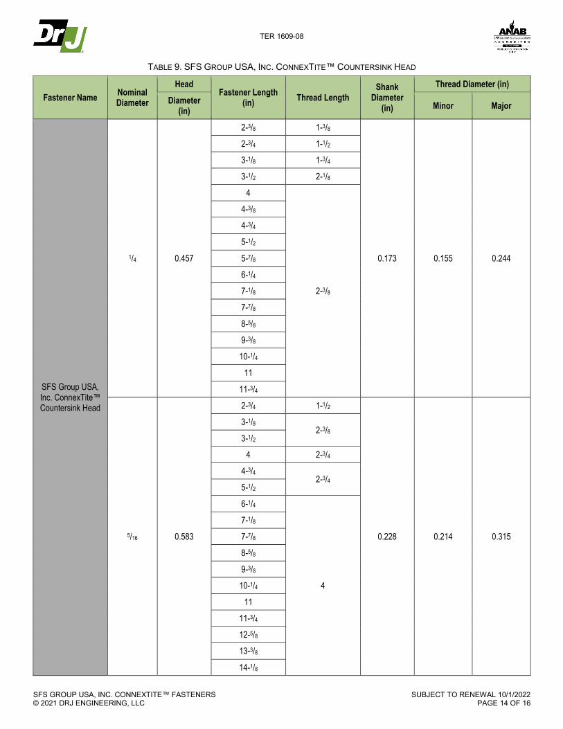
TABLE 9. SFS GROUP USA, INC. CONNEXTITE™ COUNTERSINK HEAD
Fastener Name Nominal Diameter
Head Fastener Length
(in) Thread Length Shank
Diameter (in)
Thread Diameter (in)
Diameter (in) Minor Major
SFS Group USA, Inc. ConnexTite™ Countersink Head
1/4 0.457
2-3/8 1-3/8
0.173 0.155 0.244
2-3/4 1-1/2
3-1/8 1-3/4
3-1/2 2-1/8
4
2-3/8
4-3/8
4-3/4
5-1/2
5-7/8
6-1/4
7-1/8
7-7/8
8-5/8
9-3/8
10-1/4
11
11-3/4
5/16 0.583
2-3/4 1-1/2
0.228 0.214 0.315
3-1/8 2-3/8
3-1/2
4 2-3/4
4-3/4 2-3/4
5-1/2
6-1/4
4
7-1/8
7-7/8
8-5/8
9-3/8
10-1/4
11
11-3/4
12-5/8
13-3/8
14-1/8

TER 1609-08
SFS GROUP USA, INC. CONNEXTITE™ FASTENERS © 2021 DRJ ENGINEERING, LLC
SUBJECT TO RENEWAL 10/1/2022 PAGE 15 OF 16
Fastener Name Nominal Diameter
Head Fastener Length
(in) Thread Length Shank
Diameter (in)
Thread Diameter (in)
Diameter (in) Minor Major
15
15-3/4
16-1/2
18-1/8
19-3/4
3/8 0.728
3-1/8 2-3/8
0.279 0.262 0.393
4
3-1/8 4-3/4
5-1/2
6-1/4
4
7-1/8
7-7/8
8-5/8
9-3/8
10-1/4
11
11-3/4
12-5/8
13-3/8
14-1/8
15
15-3/4
16-1/2
18-1/8
19-3/4
TER 1609-08
SFS GROUP USA, INC. CONNEXTITE™ FASTENERS © 2021 DRJ ENGINEERING, LLC
SUBJECT TO RENEWAL 10/1/2022 PAGE 16 OF 16
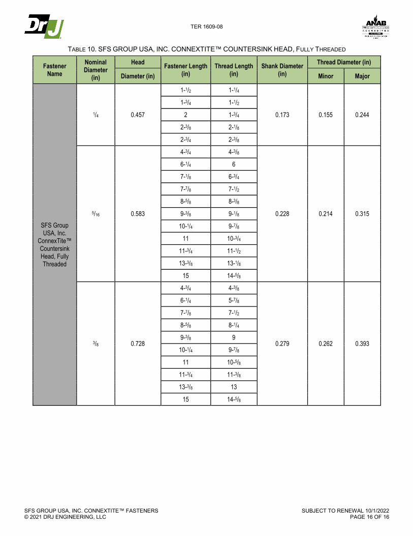
TABLE 10. SFS GROUP USA, INC. CONNEXTITE™ COUNTERSINK HEAD, FULLY THREADED
Fastener Name
Nominal Diameter
(in)
Head Fastener Length (in)
Thread Length (in)
Shank Diameter (in)
Thread Diameter (in)
Diameter (in) Minor Major
SFS Group USA, Inc.
ConnexTite™ Countersink Head, Fully Threaded
1/4 0.457
1-1/2 1-1/4
0.173 0.155 0.244
1-3/4 1-1/2
2 1-3/4
2-3/8 2-1/8
2-3/4 2-3/8
5/16 0.583
4-3/4 4-3/8
0.228 0.214 0.315
6-1/4 6
7-1/8 6-3/4
7-7/8 7-1/2
8-5/8 8-3/8
9-3/8 9-1/8
10-1/4 9-7/8
11 10-3/4
11-3/4 11-1/2
13-3/8 13-1/8
15 14-5/8
3/8 0.728
4-3/4 4-3/8
0.279 0.262 0.393
6-1/4 5-7/8
7-7/8 7-1/2
8-5/8 8-1/4
9-3/8 9
10-1/4 9-7/8
11 10-5/8
11-3/4 11-3/8
13-3/8 13
15 14-5/8


![1609 drogas[1]](https://img.pdfslide.net/doc/110x75/55c1acaebb61ebb90a8b4755/1609-drogas1.jpg)